section 230923 instrumentation and … 3: execution ... ver: 03/17 230923-2 instrumentation and...
TRANSCRIPT

VER: 04/18 230923-1 INSTRUMENTATION AND CONTROLS FOR HVAC
SECTION 230923 – INSTRUMENTATION AND CONTROLS FOR HVAC
PART 1: GENERAL ....................................................................................................................... 2 1.1 Related Sections ................................................................................................................... 2 1.2 Description ........................................................................................................................... 2 1.3 Approved Control Systems .................................................................................................... 2 1.4 Quality Assurance ................................................................................................................. 3 1.5 Codes and Standards ............................................................................................................ 3 1.6 System Performance ............................................................................................................. 3 1.7 Submittals ............................................................................................................................. 5 1.8 Warranty ............................................................................................................................... 7 1.9 Ownership of Proprietary Material ......................................................................................... 8
PART 2: PRODUCTS .................................................................................................................... 8 2.1 Materials .............................................................................................................................. 8 2.2 Communication .................................................................................................................... 8 2.3 Operator Interface ................................................................................................................ 9 2.4 Controller Software ............................................................................................................. 13 2.5 Controllers .......................................................................................................................... 14 2.6 Input and Output Interface .................................................................................................. 16 2.7 Power Supplies and Line Filtering ...................................................................................... 17 2.8 Auxiliary Control Devices .................................................................................................... 17 2.9 Wiring and Raceways ......................................................................................................... 22 2.10 Fiber Optic Cable System ................................................................................................. 22
PART 3: EXECUTION ................................................................................................................. 23 3.1 Examination ....................................................................................................................... 23 3.2 Protection ........................................................................................................................... 23 3.3 Coordination ....................................................................................................................... 23 3.4 General Workmanship ........................................................................................................ 24 3.5 Field Quality Control ........................................................................................................... 24 3.6 Existing Equipment ............................................................................................................. 24 3.7 Wiring ................................................................................................................................. 22 3.8 Communication Wiring ....................................................................................................... 26 3.9 Fiber Optic Cable ............................................................................................................... 27 3.10 Installation of Sensors ...................................................................................................... 27 3.11 Flow Switch Installation ................................................................................................... 27 3.12 Actuators ......................................................................................................................... 28 3.13 Warning Labels ............................................................................................................... 28 3.14 Identification of Hardware and Wiring .............................................................................. 28 3.15 Programming ................................................................................................................... 29 3.16 Control System Checkout and Testing ............................................................................ 29 3.17 Control System Demonstration and Acceptance .............................................................. 30 3.18 Cleaning .......................................................................................................................... 31 3.19 Training ........................................................................................................................... 31
APPENDIX A: NAMING CONVENTIONS

VER: 04/18 230923-2 INSTRUMENTATION AND CONTROLS FOR HVAC
PART 1: GENERAL
1.1 Related Sections
A. The General Conditions of the Contract, Supplementary Conditions, and General Requirements are part of this specification and shall be used in conjunction with this section as part of the contract documents.
B. The following sections constitute related work: 1. Section 23 21 23 - Hydronic Pumps 2. Section 23 36 00 - Air Terminal Units 3. Section 23 64 16 – Centrifugal Water Chillers 4. Section 23 65 00 – Cooling Towers 5. Section 23 73 13 – Indoor Central Station Air Handling Units 6. Section 23 74 13 - Outdoor Central Station Air Handling Units 7. Section 23 81 23 – Computer Room Air-Conditioners 8. Section 26 05 19 – Low Voltage Conductors and Cables 9. Section 26 05 23 – Control Voltage Cables 10. Section 26 05 33 – Raceways and Boxes
1.2 Description
A. General: The control system shall consist of a high-speed, peer-to-peer network of DDC controllers and a web-based operator interface. Depict each mechanical system and building floor plan by a point-and-click graphic. A web server with a network interface card shall gather data from this system and generate web pages accessible through a conventional web browser on each PC connected to the network. Operators shall be able to perform all normal operator functions through the web browser interface.
B. The system shall directly control HVAC equipment as specified in Section 23 09 93 – Sequence of Operations for HVAC Controls. Each zone controller shall provide occupied and unoccupied modes of operation by individual zone. Furnish energy conservation features such as optimal start and stop, night setback, request-based logic, and demand level adjustment of setpoints as specified in the sequence.
C. Provide for future system expansion to include monitoring of occupant card access, fire alarm, and lighting control systems.
D. System shall use the BACnet protocol for communication to the operator workstation or web server and for communication between control modules. I/O points, schedules, setpoints, trends, and alarms specified in Section 23 09 93 – "Sequence of Operations for HVAC Controls" shall be BACnet objects.
1.3 Approved Control Systems
A. Use control system hardware and software that meet the requirements of this specification.

VER: 04/18 230923-3 INSTRUMENTATION AND CONTROLS FOR HVAC
1.4 Quality Assurance
A. Installer and Manufacturer Qualifications 1. Installer shall have an established working relationship with Control System
Manufacturer. 2. Installer shall have successfully completed Control System Manufacturer's control
system training. Upon request, Installer shall present record of completed training including course outlines.
1.5 Codes and Standards
A. Work, materials, and equipment shall comply with the most restrictive of local, state, and federal authorities' codes and ordinances or these plans and specifications. As a minimum, the installation shall comply with current editions in effect 30 days prior to receipt of bids of the following codes:
1. National Electric Code (NEC) 2. International Building Code (IBC) 3. International Mechanical Code (IMC)
1.6 System Performance
A. Performance Standards. System shall conform to the following minimum standards over network connections. Systems shall be tested using manufacturer's recommended hardware and software for operator workstation (server and browser for web-based systems).
1. Graphic Display. A graphic with 20 dynamic points shall display with current data within 10 sec.
2. Graphic Refresh. A graphic with 20 dynamic points shall update with current data within 8 sec. and shall automatically refresh every 15 sec.
3. Configuration and Tuning Screens. Screens used for configuring, calibrating, or tuning points, PID loops, and similar control logic shall automatically refresh within 6 sec.
4. Object Command. Devices shall react to command of a binary object within 2 sec. Devices shall begin reacting to command of an analog object within 2 sec.
5. Alarm Response Time. An object that goes into alarm shall be annunciated at the workstation within 15 sec.
6. Program Execution Frequency. Custom and standard applications shall be capable of running as often as once every 5 sec. Select execution times consistent with the mechanical process under control.
7. Performance. Programmable controllers shall be able to completely execute DDC PID control loops at a frequency adjustable down to once per sec. Select execution times consistent with the mechanical process under control.
8. Multiple Alarm Annunciations. Each workstation on the network shall receive alarms within 5 sec of other workstations.
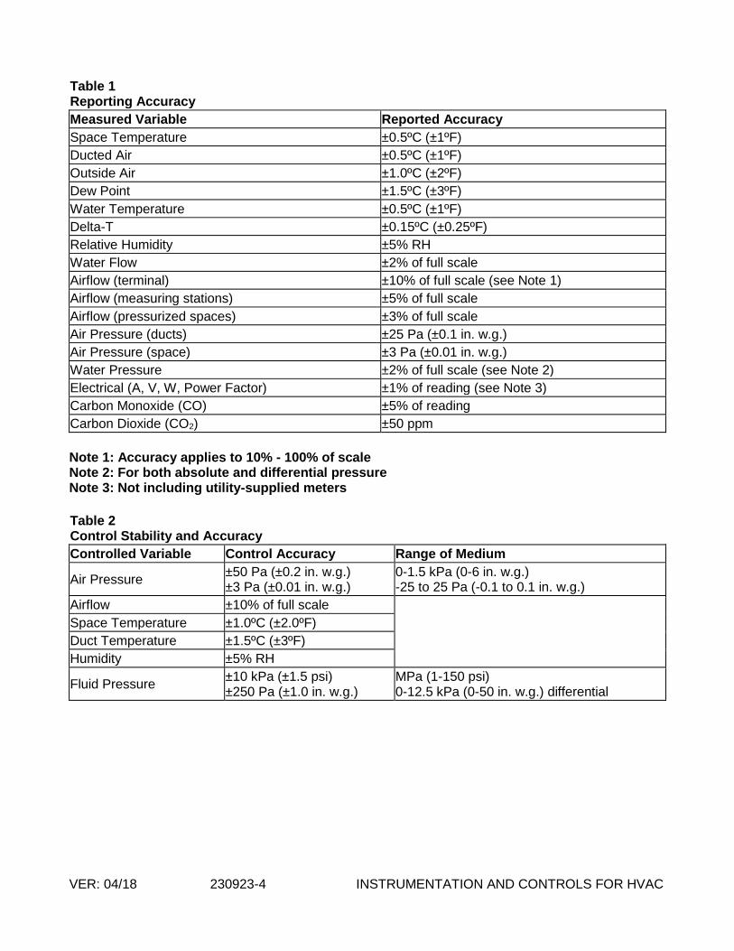
9. Reporting Accuracy. System shall report values with minimum end-to-end accuracy listed in Table 1.
10. Control Stability and Accuracy. Control loops shall maintain measured variable at setpoint within tolerances listed in Table 2.
VER: 04/18 230923-4 INSTRUMENTATION AND CONTROLS FOR HVAC
Table 1 Reporting Accuracy
Measured Variable Reported Accuracy
Space Temperature ±0.5ºC (±1ºF)
Ducted Air ±0.5ºC (±1ºF)
Outside Air ±1.0ºC (±2ºF)
Dew Point ±1.5ºC (±3ºF)
Water Temperature ±0.5ºC (±1ºF)
Delta-T ±0.15ºC (±0.25ºF)
Relative Humidity ±5% RH
Water Flow ±2% of full scale
Airflow (terminal) ±10% of full scale (see Note 1)
Airflow (measuring stations) ±5% of full scale
Airflow (pressurized spaces) ±3% of full scale
Air Pressure (ducts) ±25 Pa (±0.1 in. w.g.)
Air Pressure (space) ±3 Pa (±0.01 in. w.g.)
Water Pressure ±2% of full scale (see Note 2)
Electrical (A, V, W, Power Factor) ±1% of reading (see Note 3)
Carbon Monoxide (CO) ±5% of reading
Carbon Dioxide (CO2) ±50 ppm
Note 1: Accuracy applies to 10% - 100% of scale Note 2: For both absolute and differential pressure Note 3: Not including utility-supplied meters
Table 2 Control Stability and Accuracy
Controlled Variable Control Accuracy Range of Medium
Air Pressure ±50 Pa (±0.2 in. w.g.) ±3 Pa (±0.01 in. w.g.)
0-1.5 kPa (0-6 in. w.g.) -25 to 25 Pa (-0.1 to 0.1 in. w.g.)
Airflow ±10% of full scale
Space Temperature ±1.0ºC (±2.0ºF)
Duct Temperature ±1.5ºC (±3ºF)
Humidity ±5% RH
Fluid Pressure ±10 kPa (±1.5 psi) ±250 Pa (±1.0 in. w.g.)
MPa (1-150 psi) 0-12.5 kPa (0-50 in. w.g.) differential

VER: 04/18 230923-5 INSTRUMENTATION AND CONTROLS FOR HVAC
1.7 Submittals
A. Product Submittal Requirements: Meet requirements of Section 01 30 00 on Shop Drawings, Product Data, and Samples. Provide shop drawings and other submittals on hardware, software, and equipment to be installed or furnished in PDF file format. Begin no work until submittals have been approved for conformity with design intent. When manufacturer's cutsheets apply to a product series rather than a specific product, clearly indicate applicable data by highlighting or by other means. Clearly reference covered specification and drawing on each submittal. General catalogs shall not be accepted as cutsheets to fulfill submittal requirements. Select and show submittal quantities appropriate to scope of work. Submittal approval does not relieve Contractor of responsibility to supply sufficient quantities to complete work. Provide submittals on the following:
1. Direct Digital Control System Hardware a. Complete bill of materials indicating quantity, manufacturer, model number, and
relevant technical data of equipment to be used. b. Manufacturer's description and technical data such as performance curves,
product specifications, and installation and maintenance instructions for items listed below and for relevant items not listed below:
i. Direct digital controllers (controller panels) ii. Transducers and transmitters iii. Sensors (include accuracy data) iv. Actuators v. Valves vi. Relays and switches vii. Control panels viii. Power supplies ix. Batteries x. Operator interface equipment xi. Wiring
c. Wiring diagrams and layouts for each control panel. Show termination numbers and legend.
d. Floor plan schematic diagrams indicating field sensor and controller locations. e. Riser diagrams showing control network layout, communication protocol, and
wire types. 2. Central System Hardware and Software
a. Complete bill of material indicating quantity, manufacturer, model number, and relevant technical data of equipment used.
b. Manufacturer's description and technical data such as product specifications and installation and maintenance instructions for items listed below and for relevant items furnished under this contract not listed below:
i. Central Processing Unit (CPU) or web server ii. Monitors iii. Keyboards iv. Power supplies v. Battery backups vi. Interface equipment between CPU or server and control panels vii. Operating System software viii. Operator interface software ix. Color graphic software x. Third-party software
VER: 04/18 230923-6 INSTRUMENTATION AND CONTROLS FOR HVAC
c. Schematic diagrams of control, communication, and power wiring for central system installation. Show interface wiring to control system.
d. Network riser diagrams of wiring between central control unit and control panels.
3. Controlled Systems a. Riser diagrams showing control network layout, communication protocol, and
wire types. b. Schematic diagram of each controlled system. Label control points with point
names. Graphically show locations of control elements. c. Schematic wiring diagram of each controlled system. Label control elements
and terminals. Where a control element is also shown on control system schematic, use the same name.
d. Instrumentation list (Bill of Materials) for each controlled system. List each control system element in a table. Show element name, type of device, manufacturer, model number, and product data sheet number.
e. Complete description of control system operation including sequences of operation. Include and reference schematic diagram of controlled system. List I/O points and software points specified in Section 23 09 93. Indicate alarmed and trended points.
4. Description of process, report formats, and checklists to be used in Section 23 09 23 Article 3.17 (Control System Demonstration and Acceptance).
5. BACnet Protocol Implementation Conformance Statement (PICS) for each submitted type of controller and operator interface.
B. Schedules 1. Schedule of work provided within one month of contract award, indicating:
a. Intended sequence of work items b. Start date of each work item c. Duration of each work item d. Planned delivery dates for ordered material and equipment and expected lead
times e. Milestones indicating possible restraints on work by other trades or situations
2. Monthly written status reports indicating work completed and revisions to expected delivery dates. Include updated schedule of work.
C. Project Record Documents. Submit three copies of record (as-built) documents upon completion of installation for approval prior to final completion. Submittal shall consist of:
1. Project Record Drawings. As-built versions of submittal shop drawings provided as AutoCAD 2006 (or newer) compatible files on magnetic or optical disk (file format: .DWG, .DXF, .VSD, or comparable) and 2 prints of each drawing on 11" x 17" paper.
2. Testing and Commissioning Reports and Checklists. Completed versions of reports, checklists, and trend logs used to meet requirements of Section 23 09 23 Article 3.17 (Control System Demonstration and Acceptance).
3. Operation and Maintenance (O&M) Manual. Printed, electronic, or online help documentation of the following:
a. As-built versions of submittal product data. b. Names, addresses, and telephone numbers of installing contractors and service
representatives for equipment and control systems. c. Operator's manual with procedures for operating control systems: logging on
and off, handling alarms, producing point reports, trending data, overriding computer control, and changing setpoints and variables.

VER: 04/18 230923-7 INSTRUMENTATION AND CONTROLS FOR HVAC
d. Programming manual or set of manuals with description of programming language and syntax, of statements for algorithms and calculations used, of point database creation and modification, of program creation and modification, and of editor use.
e. Engineering, installation, and maintenance manual or set of manuals that explains how to design and install new points, panels, and other hardware; how to perform preventive maintenance and calibration; how to debug hardware problems; and how to repair or replace hardware.
f. Documentation of programs created using custom programming language including setpoints, tuning parameters, and object database. Electronic copies of programs shall meet this requirement if control logic, setpoints, tuning parameters, and objects can be viewed using furnished programming tools.
g. Graphic files, programs, and database on magnetic or optical media. h. List of recommended spare parts with part numbers and suppliers. i. Complete original-issue documentation, installation, and maintenance
information for furnished third-party hardware including computer equipment and sensors.
j. Complete original-issue copies of furnished software, including operating systems, custom programming language, operator workstation or web server software, and graphics software.
k. Licenses, guarantees, and warranty documents for equipment and systems. l. Recommended preventive maintenance procedures for system components,
including schedule of tasks such as inspection, cleaning, and calibration; time between tasks; and task descriptions.
D. Training Materials: Provide course outline and materials for each class at least six weeks before first class. Training shall be furnished via instructor-led sessions, computer-based training, or web-based training. Engineer will modify course outlines and materials if necessary to meet Owner's needs. Engineer will review and approve course outlines and materials at least three weeks before first class.
1.8 Warranty
A. Warrant work as follows: 1. Warrant labor and materials for specified control system free from defects for a period
of 24 months after final acceptance. Control system failures during warranty period shall be adjusted, repaired, or replaced at no additional cost or reduction in service to Owner. Respond during normal business hours within 24 hours of Owner's warranty service request.
2. Work shall have a single warranty date, even if Owner receives beneficial use due to early system start-up. If specified work is split into multiple contracts or a multi-phase contract, each contract or phase shall have a separate warranty start date and period.
3. If Engineer determines that equipment and systems operate satisfactorily at the end of final start-up, testing, and commissioning phase, Engineer will certify in writing that control system operation has been tested and accepted in accordance with the terms of this specification. Date of acceptance shall begin warranty period.
4. Provide updates to operator workstation or web server software, project-specific software, graphic software, database software, and firmware that resolve Contractor-identified software deficiencies at no charge during warranty period. If available, Owner can purchase in-warranty service agreement to receive upgrades for functional

VER: 04/18 230923-8 INSTRUMENTATION AND CONTROLS FOR HVAC
enhancements associated with above-mentioned items. Do not install updates or upgrades without Owner's written authorization.
5. Exception: Contractor shall not be required to warrant reused devices except those that have been rebuilt or repaired. Installation labor and materials shall be warranted. Demonstrate operable condition of reused devices at time of Engineer's acceptance.
1.9 Ownership of Proprietary Material
A. Project-specific software and documentation shall become Owner's property. This includes, but is not limited to:
1. Graphics 2. Record drawings 3. Database 4. Application programming code 5. Documentation
PART 2: PRODUCTS
2.1 Materials
A. Use new products the manufacturer is currently manufacturing and selling for use in new installations. Do not use this installation as a product test site unless explicitly approved in writing by Owner. Spare parts shall be available for at least five years after completion of this contract.
2.2 Communication
A. Control products, communication media, connectors, repeaters, hubs, and routers shall comprise a BACnet internetwork. Controller and operator interface communication shall conform to ANSI/ASHRAE Standard 135, BACnet.
B. Install new wiring and network devices as required to provide a complete and workable control network. Use existing Ethernet backbone for network segments marked "existing" on project drawings.
C. Each controller shall have a communication port for temporary connection to a laptop computer or other operator interface. Connection shall support memory downloads and other commissioning and troubleshooting operations.
D. Internetwork operator interface and value passing shall be transparent to internetwork architecture.
1. An operator interface connected to a controller shall allow the operator to interface with each internetwork controller as if directly connected. Controller information such as data, status, and control algorithms shall be viewable and editable from each internetwork controller.
2. Inputs, outputs, and control variables used to integrate control strategies across multiple controllers shall be readable by each controller on the internetwork. Program and test all cross-controller links required to execute control strategies specified in

VER: 04/18 230923-9 INSTRUMENTATION AND CONTROLS FOR HVAC
Section 23 09 93. An authorized operator shall be able to edit cross-controller links by typing a standard object address or by using a point-and-click interface.
E. Controllers with real-time clocks shall use the BACnet Time Synchronization service. System shall automatically synchronize system clocks daily from an operator-designated controller via the internetwork. If applicable, system shall automatically adjust for daylight saving and standard time.
F. System shall be expandable to at least twice the required input and output objects with additional controllers, associated devices, and wiring.
2.3 Operator Interface
A. Operator Interface. Web server shall reside on high-speed network with building controllers. Each standard browser connected to server shall be able to access all system information.
B. Communication. Web server or workstation and controllers shall communicate using BACnet protocol. Web server or workstation and control network backbone shall communicate using ISO 8802-3 (Ethernet) Data Link/Physical layer protocol and BACnet/IP addressing as specified in ANSI/ASHRAE 135, BACnet Annex J.
C. Hardware. Each workstation or web server shall consist of the following: 1. Hardware Base. Industry-standard hardware shall meet or exceed DDC system
manufacturer's recommended specifications and shall meet response times specified in Section 23 09 23 Paragraph 1.9. Hard disk shall have sufficient memory to store system software, one year of data for trended points specified in Section 23 09 93, and a system database at least twice the size of the existing database at system acceptance. Configure computers and network connections if multiple computers are required to meet specified memory and performance. Web server or workstations shall be IBM-compatible PCs with a minimum of:
a. Intel Core 2 Duo 3 GHz processor b. 2 GB RAM c. 250 GB hard disk providing data at 100 MB/sec d. 16x CD-RW/DVD drive e. Serial, parallel, and network communication ports and cables required for
proper system operation D. Operator Functions. Operator interface shall allow each authorized operator to execute the
following functions as a minimum: 1. Log In and Log Out. System shall require user name and password to log in to operator
interface. 2. Point-and-click Navigation. Operator interface shall be graphically based and shall
allow operators to access graphics for equipment and geographic areas using point-and-click navigation.
3. View and Adjust Equipment Properties. Operators shall be able to view controlled equipment status and to adjust operating parameters such as setpoints, PID gains, on and off controls, and sensor calibration.
4. View and Adjust Operating Schedules. Operators shall be able to view scheduled operating hours of each schedulable piece of equipment on a weekly or monthly calendar-based graphical schedule display, to select and adjust each schedule and time period, and to simultaneously schedule related equipment. System shall clearly show exception schedules and holidays on the schedule display.
5. View and Respond to Alarms. Operators shall be able to view a list of currently active system alarms, to acknowledge each alarm, and to clear (delete) unneeded alarms.

VER: 04/18 230923-10 INSTRUMENTATION AND CONTROLS FOR HVAC
6. View and Configure Trends. Operators shall be able to view a trend graph of each trended point and to edit graph configuration to display a specific time period or data range. Operator shall be able to create custom trend graphs to display on the same page data from multiple trended points.
7. View and Configure Reports. Operators shall be able to run preconfigured reports, to view report results, and to customize report configuration to show data of interest.
8. Manage Control System Hardware. Operators shall be able to view controller status, to restart (reboot) each controller, and to download new control software to each controller.
9. Manage Operator Access. Typically, only a few operators are authorized to manage operator access. Authorized operators shall be able to view a list of operators with system access and of functions they can perform while logged in. Operators shall be able to add operators, to delete operators, and to edit operator function authorization. Operator shall be able to authorize each operator function separately.
E. System Software. 1. Operating System. Web server shall have an industry-standard professional-grade
operating system. Acceptable systems include Microsoft Windows 7 or higher. 2. System Graphics. Operator interface shall be graphically based and shall include at
least one graphic per piece of equipment or affected zone, graphics for each direct expansion, chilled water, and hot water system, and graphics that summarize conditions on each floor of each building included in this contract. Indicate thermal comfort on floor plan summary graphics using dynamic colors to represent zone temperature relative to zone setpoint.
a. Functionality. Graphics shall allow operator to monitor system status, to view a summary of the most important data for each controlled zone or piece of equipment, to use point-and-click navigation between zones or equipment, and to edit setpoints and other specified parameters.
b. Animation. Graphics shall be able to animate by displaying different image files for changed object status.
c. Alarm Indication. Indicate areas or equipment in an alarm condition using color or other visual indicator.
F. Format. Graphics shall be saved in an industry-standard format such as BMP, JPEG, PNG, or GIF. Web-based system graphics shall be viewable on browsers compatible with World Wide Web Consortium browser standards. Web graphic format shall require no plug-in (such as HTML and JavaScript) or shall only require widely available no-cost plug-ins (such as Active-X and Adobe Flash).
G. System Tools. System shall provide the following functionality to authorized operators as an integral part of the operator interface or as stand-alone software programs. If furnished as part of the interface, the tool shall be available from each workstation or web browser interface. If furnished as a stand-alone program, software shall be installable on standard IBM-compatible PCs with no limit on the number of copies that can be installed under the system license.
1. Automatic System Database Configuration. Each workstation or web server shall store on its hard disk a copy of the current system database, including controller firmware and software. Stored database shall be automatically updated with each system configuration or controller firmware or software change.
2. Controller Memory Download. Operators shall be able to download memory from the system database to each controller.
3. System Configuration. Operators shall be able to configure the system. 4. Online Help. Context-sensitive online help for each tool shall assist operators in
operating and editing the system.

VER: 04/18 230923-11 INSTRUMENTATION AND CONTROLS FOR HVAC
5. Security. System shall require a user name and password to view, edit, add, or delete data.
a. Operator Access. Each user name and password combination shall define accessible viewing, editing, adding, and deleting functions in each system application, editor, and object.
b. Automatic Log Out. Automatically log out each operator if no keyboard or mouse activity is detected. Operators shall be able to adjust automatic log out delay.
c. Encrypted Security Data. Store system security data including operator passwords in an encrypted format. System shall not display operator passwords.
6. System Diagnostics. System shall automatically monitor controller and I/O point operation. System shall annunciate controller failure and I/O point locking (manual overriding to a fixed value).
7. Alarm Processing. System input and status objects shall be configurable to alarm on departing from and on returning to normal state. Operator shall be able to enable or disable each alarm and to configure alarm limits, alarm limit differentials, alarm states, and alarm reactions for each system object. Configure and enable alarm points as specified in Section 23 09 93 – Sequence of Operations for HVAC Controls. Alarms shall be BACnet alarm objects and shall use BACnet alarm services.
8. Alarm Messages. Alarm messages shall use an English language descriptor without acronyms or mnemonics to describe alarm source, location, and nature.
9. Alarm Reactions. Operator shall be able to configure (by object) actions workstation or web server shall initiate on receipt of each alarm. As a minimum, workstation or web server shall be able to log, print, start programs, display messages, send e-mail, send page, and audibly annunciate.
10. Alarm Maintenance. Operators shall be able to view system alarms and changes of state chronologically, to acknowledge and delete alarms, and to archive closed alarms to the workstation or web server hard disk from each workstation or web browser interface.
11. Trend Configuration. Operator shall be able to configure trend sample or change of value (COV) interval, start time, and stop time for each system data object and shall be able to retrieve data for use in spreadsheets and standard database programs. Controller shall sample and store trend data and shall be able to archive data to the hard disk. Configure trends as specified in Section 23 09 93 – Sequence of Operations for HVAC Controls. Trends shall be BACnet trend objects.
12. Object and Property Status and Control. Operator shall be able to view, and to edit if applicable, the status of each system object and property by menu, on graphics, or through custom programs.
13. Reports and Logs. Operator shall be able to select, to modify, to create, and to print reports and logs. Operator shall be able to store report data in a format accessible by standard spreadsheet and word processing programs.
14. Standard Reports. Furnish the following standard system reports: a. Objects. System objects and current values filtered by object type, by status (in
alarm, locked, normal), by equipment, by geographic location, or by combination of filter criteria.
b. Alarm Summary. Current alarms and closed alarms. System shall retain closed alarms for an adjustable period.
c. Logs. System shall log the following to a database or text file and shall retain data for an adjustable period:
VER: 04/18 230923-12 INSTRUMENTATION AND CONTROLS FOR HVAC
i. Alarm History. ii. Trend Data. Operator shall be able to select trends to be logged. iii. Operator Activity. At a minimum, system shall log operator log in and log
out, control parameter changes, schedule changes, and alarm acknowledgment and deletion. System shall date and time stamp logged activity.
15. Graphics Generation. Graphically based tools and documentation shall allow Operator to edit system graphics, to create graphics, and to integrate graphics into the system. Operator shall be able to add analog and binary values, dynamic text, static text, and animation files to a background graphic using a mouse.
16. Graphics Library. Complete library of standard HVAC equipment graphics shall include equipment such as chillers, boilers, air handlers, terminals, fan coils, and unit ventilators. Library shall include standard symbols for other equipment including fans, pumps, coils, valves, piping, dampers, and ductwork. Library graphic file format shall be compatible with graphics generation tools.
17. Custom Application Programming. Operator shall be able to create, edit, debug, and download custom programs. System shall be fully operable while custom programs are edited, compiled, and downloaded. Programming language shall have the following features:
a. Language. Language shall be graphically based or English language oriented. If graphically based, language shall use function blocks arranged in a logic diagram that clearly shows control logic flow. Function blocks shall directly provide functions listed below, and operators shall be able to create custom or compound function blocks. If English language oriented, language shall be based on the syntax of BASIC, FORTRAN, C, or PASCAL, and shall allow for free-form programming that is not column-oriented or "fill-in-the-blanks."
b. Programming Environment. Tool shall provide a full-screen, cursor-and-mouse-driven programming environment that incorporates word processing features such as cut and paste. Operators shall be able to insert, add, modify, and delete custom programming code, and to copy blocks of code to a file library for reuse in other control programs.
c. Independent Program Modules. Operator shall be able to develop independently executing program modules that can disable, enable and exchange data with other program modules.
d. Debugging and Simulation. Operator shall be able to step through the program observing intermediate values and results. Operator shall be able to adjust input variables to simulate actual operating conditions. Operator shall be able to adjust each step's time increment to observe operation of delays, integrators, and other time-sensitive control logic. Debugger shall provide error messages for syntax and for execution errors.
e. Conditional Statements. Operator shall be able to program conditional logic using compound Boolean (AND, OR, and NOT) and relational (EQUAL, LESS THAN, GREATER THAN, NOT EQUAL) comparisons.
f. Mathematical Functions. Language shall support floating-point addition, subtraction, multiplication, division, and square root operations, as well as absolute value calculation and programmatic selection of minimum and maximum values from a list of values.
g. Variables: Operator shall be able to use variable values in program conditional statements and mathematical functions.

VER: 04/18 230923-13 INSTRUMENTATION AND CONTROLS FOR HVAC
i. Time Variables. Operator shall be able to use predefined variables to represent time of day, day of the week, month of the year, and date. Other predefined variables or simple control logic shall provide elapsed time in seconds, minutes, hours, and days. Operator shall be able to start, stop, and reset elapsed time variables using the program language.
ii. System Variables. Operator shall be able to use predefined variables to represent status and results of Controller Software and shall be able to enable, disable, and change setpoints of Controller Software as described in Controller Software section.
H. Portable Operator's Terminal. Provide all necessary software to configure an IBM-compatible laptop computer for use as a Portable Operator's Terminal. Operator shall be able to connect configured Terminal to the system network or directly to each controller for programming, setting up, and troubleshooting.
I. Operator Workstation: Web server or workstation shall conform to BACnet Operator Workstation (B-OWS) device profile or BACnet Advanced Workstation (B-AWS) as specified in ANSI/ASHRAE 135, BACnet Annex L and shall be listed as a certified B-OWS or B-AWS in the BACnet Testing Laboratories (BTL) Product Listing.
2.4 Controller Software
A. Building and energy management application software shall reside and operate in system controllers. Applications shall be editable through operator workstation, web browser interface, or engineering workstation.
B. System Security. See Paragraph 2.3.F.5 (Security) and Paragraph 2.3.F.15.c (Operator Activity).
C. Scheduling. See Paragraph 2.3.D.4 (View and Adjust Operating Schedules). System shall provide the following schedule options as a minimum:
1. Weekly. Provide separate schedules for each day of the week. Each schedule shall be able to include up to 5 occupied periods (5 start-stop pairs or 10 events).
2. Exception. Operator shall be able to designate an exception schedule for each of the next 365 days. After an exception schedule has executed, system shall discard and replace exception schedule with standard schedule for that day of the week.
3. Holiday. Operator shall be able to define 24 special or holiday schedules of varying length on a scheduling calendar that repeats each year.
D. System Coordination. Operator shall be able to group related equipment based on function and location and to use these groups for scheduling and other applications.
E. Binary and Analog Alarms. See Paragraph 2.3.F.7 (Alarm Processing). F. Alarm Reporting. See Paragraph 2.3.F.9 (Alarm Reactions). G. Remote Communication. System shall automatically contact operator workstation or server on
receipt of critical alarms. If no network connection is available, system shall use a modem connection.
H. Demand Limiting. 1. System shall monitor building power consumption from building power meter pulse
generator signals or from building feeder line watt transducer or current transformer. 2. When power consumption exceeds adjustable levels, system shall automatically adjust
setpoints, de-energize low-priority equipment, and take other programmatic actions to reduce demand as specified in Section 23 09 93 – Sequence of Operations for HVAC Controls. When demand drops below adjustable levels, system shall restore loads as specified.
VER: 04/18 230923-14 INSTRUMENTATION AND CONTROLS FOR HVAC
I. Maintenance Management. System shall generate maintenance alarms when equipment exceeds adjustable runtime, equipment starts, or performance limits. Configure and enable maintenance alarms as specified in Section 23 09 93 – Sequence of Operations for HVAC Controls.
J. Sequencing. Application software shall sequence chillers, boilers, and pumps as specified in Section 23 09 93 – Sequence of Operations for HVAC Controls.
K. PID Control. System shall provide direct- and reverse-acting PID (proportional-integral-derivative) algorithms. Each algorithm shall have anti-windup and selectable controlled variable, setpoint, and PID gains. Each algorithm shall calculate a time-varying analog value that can be used to position an output or to stage a series of outputs.
L. PID controller should also be able to auto tune. M. Staggered Start. System shall stagger controlled equipment restart after power outage.
Operator shall be able to adjust equipment restart order and time delay between equipment restarts.
N. Energy Calculations. 1. System shall accumulate and convert instantaneous power (kW) or flow rates (L/s
[gpm]) to energy usage data. 2. System shall calculate a sliding-window average (rolling average). Operator shall be
able to adjust window interval to 15 minutes, 30 minutes, or 60 minutes. O. Anti-Short Cycling. Binary output objects shall be protected from short cycling by means of
adjustable minimum on-time and off-time settings. P. On and Off Control with Differential. System shall provide direct- and reverse-acting on and off
algorithms with adjustable differential to cycle a binary output based on a controlled variable and setpoint.
Q. Runtime Totalization. System shall provide an algorithm that can totalize runtime for each binary input and output. Operator shall be able to enable runtime alarm based on exceeded adjustable runtime limit. Configure and enable runtime totalization and alarms as specified in Section 23 09 93 – Sequence of Operations for HVAC Controls.
2.5 Controllers
A. General. Provide Building Controllers (BC), Advanced Application Controllers (AAC), Application Specific Controllers (ASC), Smart Actuators (SA), and Smart Sensors (SS) as required to achieve performance specified in Section 23 09 23 Article 1.9 (System Performance). Every device in the system which executes control logic and directly controls HVAC equipment must conform to a standard BACnet Device profile as specified in ANSI/ASHRAE 135, BACnet Annex L. Unless otherwise specified, hardwired actuators and sensors may be used in lieu of BACnet Smart Actuators and Smart Sensors.
B. BACnet. 1. Building Controllers (BCs). Each BC shall conform to BACnet Building Controller (B-
BC) device profile as specified in ANSI/ASHRAE 135, BACnet Annex L and shall be listed as a certified B-BC in the BACnet Testing Laboratories (BTL) Product Listing. Combination Building Controllers (BC) and Application Specific Controllers (ASC) such as the JCI NCE shall not be used.
2. Advanced Application Controllers (AACs). Each AAC shall conform to BACnet Advanced Application Controller (B-AAC) device profile as specified in ANSI/ASHRAE 135, BACnet Annex L and shall be listed as a certified B-AAC in the BACnet Testing Laboratories (BTL) Product Listing.
3. Application Specific Controllers (ASCs). Each ASC shall conform to BACnet Application Specific Controller (B-ASC) device profile as specified in ANSI/ASHRAE

VER: 04/18 230923-15 INSTRUMENTATION AND CONTROLS FOR HVAC
135, BACnet Annex L and shall be listed as a certified B-ASC in the BACnet Testing Laboratories (BTL) Product Listing.
4. Smart Actuators (SAs). Each SA shall conform to BACnet Smart Actuator (B-SA) device profile as specified in ANSI/ASHRAE 135, BACnet Annex L and shall be listed as a certified B-SA in the BACnet Testing Laboratories (BTL) Product Listing.
5. Smart Sensors (SSs). Each SS shall conform to BACnet Smart Sensor (B-SS) device profile as specified in ANSI/ASHRAE 135, BACnet Annex L and shall be listed as a certified B-SS in the BACnet Testing Laboratories (BTL) Product Listing.
6. BACnet Communication. a. Each BC shall reside on or be connected to a BACnet network using ISO 8802-
3 (Ethernet) Data Link/Physical layer protocol and BACnet/IP addressing. b. BACnet routing shall be performed by BCs or other BACnet device routers as
necessary to connect BCs to networks of AACs and ASCs. c. Each AAC shall reside on a BACnet network using ISO 8802-3 (Ethernet) Data
Link/Physical layer protocol with BACnet/IP addressing, or it shall reside on a BACnet network using the ARCNET or MS/TP Data Link/Physical layer protocol.
d. Each ASC shall reside on a BACnet network using the ARCNET or MS/TP Data Link/Physical layer protocol.
e. Each SA shall reside on a BACnet network using the ARCNET or MS/TP Data Link/Physical layer protocol.
f. Each SS shall reside on a BACnet network using ISO 8802-3 (Ethernet) Data Link/Physical layer protocol with BACnet/IP addressing, or it shall reside on a BACnet network using ARCNET or MS/TP Data Link/Physical layer protocol.
C. Communication. 1. Service Port. Each controller shall provide a service communication port for connection
to a Portable Operator's Terminal. Connection shall be extended to space temperature sensor ports where shown on drawings.
2. Signal Management. BC and ASC operating systems shall manage input and output communication signals to allow distributed controllers to share real and virtual object information and to allow for central monitoring and alarms.
3. Data Sharing. Each BC and AAC shall share data as required with each networked BC and AAC.
4. Stand-Alone Operation. Each piece of equipment specified in Section 23 09 93 shall be controlled by a single controller to provide stand-alone control in the event of communication failure. All I/O points specified for a piece of equipment shall be integral to its controller. Provide stable and reliable stand-alone control using default values or other method for values normally read over the network.
D. Environment. Controller hardware shall be suitable for anticipated ambient conditions. 1. Controllers used outdoors or in wet ambient conditions shall be mounted in waterproof
enclosures and shall be rated for operation at -29°C to 60°C (-20°F to 140°F). 2. Controllers used in conditioned space shall be mounted in dust-protective enclosures
and shall be rated for operation at 0°C to 50°C (32°F to 120°F). E. Keypad. Provide a local keypad and display for each BC and AAC. Operator shall be able to
use keypad to view and edit data. Keypad and display shall require password to prevent unauthorized use. If the manufacturer does not normally provide a keypad and display for each BC and AAC, provide the software and any interface cabling needed to use a laptop computer as a Portable Operator's Terminal for the system.
F. Real-Time Clock. Controllers that perform scheduling shall have a real-time clock. G. Serviceability.

VER: 04/18 230923-16 INSTRUMENTATION AND CONTROLS FOR HVAC
1. Controllers shall have diagnostic LEDs for power, communication, and processor. 2. Wires shall be connected to a field-removable modular terminal strip or to a termination
card connected by a ribbon cable. 3. Each BC and AAC shall continually check its processor and memory circuit status and
shall generate an alarm on abnormal operation. System shall continuously check controller network and generate alarm for each controller that fails to respond.
H. Memory. 1. Controller memory shall support operating system, database, and programming
requirements. 2. Each BC and AAC shall retain BIOS and application programming for at least 72 hours
in the event of power loss. 3. Each ASC and SA shall use nonvolatile memory and shall retain BIOS and application
programming in the event of power loss. System shall automatically download dynamic control parameters following power loss.
I. Immunity to Power and Noise. Controllers shall be able to operate at 90% to 110% of nominal voltage rating and shall perform an orderly shutdown below 80% nominal voltage. Operation shall be protected against electrical noise of 5 to 120 Hz and from keyed radios up to 5 W at 1 m (3 ft.).
J. Transformer. ASC power supply shall be fused or current limiting and shall be rated at a minimum of 125% of ASC power consumption.
2.6 Input and Output Interface
A. General. Hard-wire input and output points to BCs, AACs, ASCs, or SAs. B. Protection. Shorting an input or output point to itself, to another point, or to ground shall cause
no controller damage. Input or output point contact with up to 24 V for any duration shall cause no controller damage.
C. Binary Inputs. Binary inputs shall monitor the on and off signal from a remote device. Binary inputs shall provide a wetting current of at least 12 mA and shall be protected against contact bounce and noise. Binary inputs shall sense dry contact closure without application of power external to the controller.
D. Pulse Accumulation Inputs. Pulse accumulation inputs shall conform to binary input requirements and shall accumulate up to 10 pulses per second.
E. Analog Inputs. Analog inputs shall monitor low-voltage (0-10 Vdc), current (4-20 mA), or resistance (thermistor or RTD) signals. Analog inputs shall be compatible with and field configurable to commonly available sensing devices.
F. Binary Outputs. Binary outputs shall send an on-or-off signal for on and off control. Building Controller binary outputs shall have three-position (on-off-auto) override switches and status lights. Outputs shall be selectable for normally open or normally closed operation.
G. Analog Outputs. Analog outputs shall send a modulating 0-10 Vdc or 4-20 mA signal as required to properly control output devices. Each Building Controller analog output shall have a two-position (auto-manual) switch, a manually adjustable potentiometer, and status lights. Analog outputs shall not drift more than 0.4% of range annually.
H. Tri-State Outputs. Control three-point floating electronic actuators without feedback with tri-state outputs (two coordinated binary outputs). Tri-State outputs may be used to provide analog output control in zone control and terminal unit control applications such as VAV terminal units, duct-mounted heating coils, and zone dampers.

VER: 04/18 230923-17 INSTRUMENTATION AND CONTROLS FOR HVAC
I. Universal Inputs and Outputs. Inputs and outputs that can be designated as either binary or analog in software shall conform to the provisions of this section that are appropriate for their designated use.
2.7 Power Supplies and Line Filtering
A. Power Supplies. Control transformers shall be UL listed. Furnish Class 2 current-limiting type or furnish over-current protection in primary and secondary circuits for Class 2 service in accordance with NEC requirements. Limit connected loads to 80% of rated capacity.
1. DC power supply output shall match output current and voltage requirements. Unit shall be full-wave rectifier type with output ripple of 5.0 mV maximum peak-to-peak. Regulation shall be 1.0% line and load combined, with 100-microsecond response time for 50% load changes. Unit shall have built-in over-voltage and over-current protection and shall be able to withstand 150% current overload for at least three seconds without trip-out or failure.
a. Unit shall operate between 0°C and 50°C (32°F and 120°F). EM/RF shall meet FCC Class B and VDE 0871 for Class B and MILSTD 810C for shock and vibration.
b. Line voltage units shall be UL recognized and CSA listed. B. Power Line Filtering.
1. Provide internal or external transient voltage and surge suppression for workstations and controllers. Surge protection shall have:
b. Dielectric strength of 1000 V minimum c. Response time of 10 nanoseconds or less d. Transverse mode noise attenuation of 65 dB or greater e. Common mode noise attenuation of 150 dB or greater at 40-100 Hz
2.8 Auxiliary Control Devices
A. Motorized Control Dampers. 1. Type. Control dampers shall have linear flow characteristics and shall be parallel- or
opposed-blade type as specified below or as scheduled on drawings. a. Outdoor and return air mixing dampers and face-and-bypass dampers shall be
parallel-blade and shall direct airstreams toward each other. b. Other modulating dampers shall be opposed-blade. c. Two-position shutoff dampers shall be parallel- or opposed-blade with blade
and side seals. 2. Frame. Damper frames shall be 2.38 mm (13 gage) galvanized steel channel or 3.175
mm (1/8 in.) extruded aluminum with reinforced corner bracing. 3. Blades. Damper blades shall not exceed 20 cm (8 in.) in width or 125 cm (48 in.) in
length. Blades shall be suitable for medium velocity (10 m/s [2000 fpm]) performance. Blades shall be not less than 1.5875 mm (16 gage).
4. Shaft Bearings. Damper shaft bearings shall be as recommended by manufacturer for application, oil impregnated sintered bronze, or better.
5. Seals. Blade edges and frame top and bottom shall have replaceable seals of butyl rubber or neoprene. Side seals shall be spring-loaded stainless steel. Blade seals shall leak no more than 50 L/s-m 2 (10 cfm per ft2) at 1000 Pa (4 in. w.g.) differential pressure. Blades shall be airfoil type suitable for wide-open face velocity of 7.5 m/s (1500 fpm).

VER: 04/18 230923-18 INSTRUMENTATION AND CONTROLS FOR HVAC
6. Sections. Damper sections shall not exceed 125 cm - 150 cm (48 in. - 60 in.). Each section shall have at least one damper actuator.
7. Linkages. Dampers shall have exposed linkages. B. Electric Damper and Valve Actuators.
1. Stall Protection. Mechanical or electronic stall protection shall prevent actuator damage throughout the actuator's rotation.
2. Spring-return Mechanism. Actuators used for power-failure and safety applications shall have an internal mechanical spring-return mechanism or an uninterruptible power supply (UPS).
3. Signal and Range. Proportional actuators shall accept a 0-10 Vdc or a 0-20 mA control signal and shall have a 2-10 Vdc or 4-20 mA operating range. (Floating motor actuators may be substituted for proportional actuators in terminal unit applications as described in paragraph 2.6H.)
4. Wiring. 24 Vac and 24 Vdc actuators shall operate on Class 2 wiring. 5. Manual Positioning. Operators shall be able to manually position each actuator when
the actuator is not powered. Non-spring-return actuators shall have an external manual gear release. Spring-return actuators with more than 7 N·m (60 in.-lb.) torque capacity shall have a manual crank.
C. Control Valves. 1. General. Select body and trim materials in accordance with manufacturer's
recommendations for design conditions and service shown. 2. Type. Provide two- or three-way control valves for two-position or modulating service
as shown. 3. Water Valves.
a. Valves providing two-position service shall be quick opening. Two-way valves shall have replaceable disc or ball.
b. Close-off (Differential) Pressure Rating. Valve actuator and trim shall provide the following minimum close-off pressure ratings.
i. Two-way: 150% of total system (pump) head. ii. Three-way: 300% of pressure differential between ports A and B at
design flow or 100% of total system (pump) head. c. Ports. Valves providing modulating service shall have equal percentage ports. d. Sizing.
i. Two-position service: line size. ii. Two-way modulating service: select pressure drop equal to the greatest
of twice the pressure drop through heat exchanger (load), 50% of the pressure difference between supply and return mains, or 35 kPa (5 psi).
iii. Three-way modulating service: select pressure drop equal to the smaller of twice the pressure drop through the coil exchanger (load) or 35 kPa (5 psi).
e. Fail Position. Water valves shall fail normally open or closed as follows unless otherwise specified.
i. Water zone valves: normally open. ii. Heating coils in air handlers: normally open. iii. Chilled water control valves: normally closed. iv. Other applications: as scheduled or as required by sequences of
operation. 4. Steam Valves.
a. Close-off (Differential) Pressure Rating. Valve actuator and trim shall provide minimum close-off pressure rating equal to 150% of operating (inlet) pressure.
VER: 04/18 230923-19 INSTRUMENTATION AND CONTROLS FOR HVAC
b. Ports. Valves providing modulating service shall have linear ports. c. Sizing.
i. Two-position service: select pressure drop equal to 10%-20% of inlet psig.
ii. Modulating service at 100 kPa (15 psig) or less: select pressure drop equal to 80% of inlet psig.
iii. Modulating service at 101-350 kPa (16-50 psig): select pressure drop equal to 50% of inlet psig.
iv. Modulating service at over 350 kPa (50 psig): select pressure drop as scheduled on drawings.
D. Binary Temperature Devices. 1. Low-Voltage Space Thermostats. Low-voltage space thermostats shall be 24 V,
bimetal-operated, mercury-switch type, with adjustable or fixed anticipation heater, concealed setpoint adjustment, 13°C-30°C (55°F-85°F) setpoint range, 1°C (2°F) maximum differential, and vented ABS plastic cover.
2. Line-Voltage Space Thermostats. Line-voltage space thermostats shall be bimetal-actuated, open-contact type or bellows-actuated, enclosed, snap-switch type or equivalent solid-state type, with heat anticipator, UL listing for electrical rating, concealed setpoint adjustment, 13°C-30°C (55°F-85°F) setpoint range, 1°C (2°F) maximum differential, and vented ABS plastic cover.
3. Low-Limit Thermostats. Low-limit airstream thermostats shall be UL listed, vapor pressure type. Element shall be at least 6 m (20 ft.) long. Element shall sense temperature in each 30 cm (1 ft.) section and shall respond to lowest sensed temperature. Low-limit thermostat shall be manual reset only.
E. Temperature Sensors. 1. Type. Temperature sensors shall be Resistance Temperature Device (RTD) or
thermistor. 2. Duct Sensors. Duct sensors shall be single point or averaging as shown. Averaging
sensors shall be a minimum of 1.5 m (5 ft.) in length per 1 m2(10 ft2) of duct cross-section.
3. Immersion Sensors. Provide immersion sensors with a separable stainless steel well. Well pressure rating shall be consistent with system pressure it will be immersed in. Well shall withstand pipe design flow velocities.
4. Space Sensors. Space sensors shall have remote setpoint adjustment, vertical wall box enclosure, SA Bus screw terminal block, BACnet Listed sensor, and communication port.
5. Differential Sensors. Provide matched sensors for differential temperature measurement.
F. Humidity Sensors. 1. Duct and room sensors shall have a sensing range of 20%-80%. 2. Duct sensors shall have a sampling chamber. 3. Outdoor air humidity sensors shall have a sensing range of 20%-95% RH and shall be
suitable for ambient conditions of 40°C-75°C (40°F-170°F). 4. Humidity sensors shall not drift more than 1% of full scale annually.
G. Flow Switches. Flow-proving switches shall be solid state thermal sensor or differential pressure type (air or water service) as shown. Differential pressure switches shall be UL listed, SPDT snap-acting, and pilot duty rated (125 VA minimum).
1. Solid state thermal sensors shall have adjustable sensitivity and NEMA 1 enclosure unless otherwise specified.

VER: 04/18 230923-20 INSTRUMENTATION AND CONTROLS FOR HVAC
2. Differential pressure switches shall have scale range and differential suitable for intended application and NEMA 1 enclosure unless otherwise specified.
H. Relays. 1. Control Relays. Control relays shall be plug-in type, UL listed, and shall have dust
cover and LED "energized" indicator. Contact rating, configuration, and coil voltage shall be suitable for application.
2. Time Delay Relays. Time delay relays shall be solid-state plug-in type, UL listed, and shall have adjustable time delay. Delay shall be adjustable ±100% from setpoint shown. Contact rating, configuration, and coil voltage shall be suitable for application. Provide NEMA 1 enclosure for relays not installed in local control panel.
I. Override Timers. 1. Unless implemented in control software, override timers shall be spring-wound line
voltage, UL Listed, with contact rating and configuration required by application. Provide 0-6 hour calibrated dial unless otherwise specified. Flush mount timer on local control panel face or where shown.
J. Current Transmitters. 1. AC current transmitters shall be self-powered, combination split-core current
transformer type with built-in rectifier and high-gain servo amplifier with 4-20 mA two-wire output. Full-scale unit ranges shall be 10 A, 20 A, 50 A, 100 A, 150 A, and 200 A, with internal zero and span adjustment. Unit accuracy shall be ±1% full-scale at 500 ohm maximum burden.
2. Transmitter shall meet or exceed ANSI/ISA S50.1 requirements and shall be UL/CSA recognized.
3. Unit shall be split-core type for clamp-on installation on existing wiring. K. Current Transformers.
1. AC current transformers shall be UL/CSA recognized and shall be completely encased (except for terminals) in approved plastic material.
2. Transformers shall be available in various current ratios and shall be selected for ±1% accuracy at 5 A full-scale output.
3. Use fixed-core transformers for new wiring installation and split-core transformers for existing wiring installation.
L. Voltage Transmitters. 1. AC voltage transmitters shall be self-powered single-loop (two-wire) type, 4-20 mA
output with zero and span adjustment. 2. Adjustable full-scale unit ranges shall be 100-130 Vac, 200-250 Vac, 250-330 Vac, and
400-600 Vac. Unit accuracy shall be ±1% full-scale at 500 ohm maximum burden. 3. Transmitters shall meet or exceed ANSI/ISA S50.1 requirements and shall be UL/CSA
recognized at 600 Vac rating. M. Voltage Transformers.
1. AC voltage transformers shall be UL/CSA recognized, 600 Vac rated, and shall have built-in fuse protection.
2. Transformers shall be suitable for ambient temperatures of 4°C-55°C (40°F-130°F) and shall provide ±0.5% accuracy at 24 Vac and 5 VA load.
3. Windings (except for terminals) shall be completely enclosed with metal or plastic. N. Power Monitors.
1. Power monitors shall be three-phase type and shall have three-phase disconnect and shorting switch assembly, UL listed voltage transformers, and UL listed split-core current transformers.

VER: 04/18 230923-21 INSTRUMENTATION AND CONTROLS FOR HVAC
2. Power monitors shall provide selectable output: rate pulse for kWh reading or 4-20 mA for kW reading. Power monitors shall operate with 5 A current inputs and maximum error of ±2% at 1.0 power factor or ±2.5% at 0.5 power factor.
O. Current Switches. 1. Current-operated switches shall be self-powered, solid-state with adjustable trip
current. Select switches to match application current and DDC system output requirements.
P. Pressure Transducers. 1. Transducers shall have linear output signal and field-adjustable zero and span. 2. Continuous operating conditions of positive or negative pressure 50% greater than
calibrated span shall not damage transducer sensing elements. 3. Water pressure transducer diaphragm shall be stainless steel with minimum proof
pressure of 1000 kPa (150 psi). Transducer shall have 4-20 mA output, suitable mounting provisions, and block and bleed valves.
4. Water differential pressure transducer diaphragm shall be stainless steel with minimum proof pressure of 1000 kPa (150 psi). Over-range limit (differential pressure) and maximum static pressure shall be 2000 kPa (300 psi.) Transducer shall have 4-20 mA output, suitable mounting provisions, and 5-valve manifold.
Q. Differential Pressure Switches. Differential pressure switches (air or water service) shall be UL listed, SPDT snap-acting, pilot duty rated (125 VA minimum) and shall have scale range and differential suitable for intended application and NEMA 1 enclosure unless otherwise specified.
R. Pressure-Electric (PE) Switches. PE switches shall be UL listed, pilot duty rated (125 VA minimum) or motor control rated, metal or neoprene diaphragm actuated, operating pressure rated for 0-175 kPa (0-25 psig), with calibrated scale minimum setpoint range of 14-125 kPa (2-18 psig).
1. Provide one- or two-stage switch action (SPDT, DPST, or DPDT) as required by application.
2. Switches shall be open type (panel-mounted). Exception: Switches shall be enclosed type for remote installation. Enclosed type shall be NEMA 1 unless otherwise specified.
3. Each pneumatic signal line to PE switches shall have permanent indicating gauge. S. Local Control Panels.
1. Indoor control panels shall be fully enclosed NEMA 1 construction with hinged door key-lock latch and removable sub-panels. A common key shall open each control panel and sub-panel.
2. Prewire internal and face-mounted device connections with color-coded stranded conductors tie-wrapped or neatly installed in plastic troughs. Field connection terminals shall be UL listed for 600 V service, individually identified per control and interlock drawings, with adequate clearance for field wiring.
3. Each local panel shall have a control power source power switch (on-off) with overcurrent protection.
T. Environment. Auxiliary Control Devices shall be suitable for anticipated ambient conditions. 1. Devices used outdoors or in wet ambient conditions shall be mounted in waterproof
enclosures and shall be rated for operation at -29°C to 60°C (-20°F to 140°F). 2. Devices used in conditioned space shall be mounted in dust-protective enclosures and
shall be rated for operation at 0°C to 50°C (32°F to 120°F). 3. The Devices themselves shall possess the appropriate NEMA Rating for the intended
environment. Plastic covers, canvas bags, or other supplemental enclosures are unacceptable.

VER: 04/18 230923-22 INSTRUMENTATION AND CONTROLS FOR HVAC
2.9 Wiring and Raceways
A. General. Provide copper wiring, plenum cable, and raceways as specified in applicable sections of Division 26.
B. Insulated wire shall use copper conductors and shall be UL listed for 90°C (200°F) minimum service.
C. Conductors shall conform to the following table:
NOTE: The Windy City Wire Part Number is the basis of design. Comparable cables from other manufacturers may be acceptable.
2.10 Fiber Optic Cable System
A. Optical Cable. Optical cables shall be duplex 900 mm tight-buffer construction designed for intra-building environments. Sheath shall be UL listed OFNP in accordance with NEC Article 770. Optical fiber shall meet the requirements of FDDI, ANSI X3T9.5 PMD for 62.5/125mm.
B. Connectors. Field terminate optical fibers with ST type connectors. Connectors shall have ceramic ferrules and metal bayonet latching bodies.
USAGE SHEATH COLOR GAGE/QTY SHIELDED PLENUM RATED WCW Part Number
Analog Inputs Yellow 18-2 Yes Yes WCW-18/2YEL-WC
Analog Inputs Yellow 18-3 Yes Yes WCW-18/3YEL-WC
Analog Outputs Tan 18-2 Yes Yes WCW-18/2TAN-WC
Analog Outputs Tan 18-3 Yes Yes WCW-18/3TAN-WC
Binary Inputs Orange 18-2 Yes Yes WCW-18/2ORG-WC
Binary Outputs Violet 18-2 Yes Yes WCW-18/2VLT-WC
24v Power White with Red Stripe 18-2 No Yes 002361
24v Power White with Blue Stripe 16-2 No Yes 001362
24v Power White with Yellow Stripe 14-2 No Yes 007963
FC Bus Yellow with Blue Stripe 22-3 Yes Yes 0043339
SA Bus Brown 22-2P Yes Yes WCW-22/2P-SA-PLN

VER: 04/18 230923-23 INSTRUMENTATION AND CONTROLS FOR HVAC
PART 3: EXECUTION
3.1 Examination
A. Thoroughly examine project plans for control device and equipment locations. Report discrepancies, conflicts, or omissions to Architect or Engineer for resolution before starting rough-in work.
B. Inspect site to verify that equipment can be installed as shown. Report discrepancies, conflicts, or omissions to Engineer for resolution before starting rough-in work.
C. Examine drawings and specifications for work of others. Report inadequate headroom or space conditions or other discrepancies to Engineer and obtain written instructions for changes necessary to accommodate Section 23 09 23 work with work of others. Controls Contractor shall perform at his expense necessary changes in specified work caused by failure or neglect to report discrepancies.
3.2 Protection
A. Controls Contractor shall protect against and be liable for damage to work and to material caused by Contractor's work or employees.
B. Controls Contractor shall be responsible for work and equipment until inspected, tested, and accepted. Protect material not immediately installed. Close open ends of work with temporary covers or plugs during storage and construction to prevent entry of foreign objects.
3.3 Coordination
A. Site. 1. Assist in coordinating space conditions to accommodate the work of each trade where
work will be installed near or will interfere with work of other trades. If installation without coordination causes interference with work of other trades, Contractor shall correct conditions without extra charge.
2. Coordinate and schedule work with other work in the same area and with work dependent upon other work to facilitate mutual progress.
B. Submittals. See Section 23 09 23 Article 1.10 (Submittals). C. Test and Balance.
1. Provide Test and Balance Contractor a single set of necessary tools to interface to control system for testing and balancing.
2. Train Test and Balance Contractor to use control system interface tools. 3. Provide a qualified technician to assist with testing and balancing the first 20 terminal
units. 4. Test and Balance Contractor shall return tools undamaged and in working condition at
completion of testing and balancing. D. Life Safety.
1. Duct smoke detectors required for air handler shutdown are provided under Division 28. Interlock smoke detectors to air handlers for shutdown as specified in Section 23 09 93 – Sequence of Operations for HVAC Controls.

VER: 04/18 230923-24 INSTRUMENTATION AND CONTROLS FOR HVAC
2. Smoke dampers and actuators required for duct smoke isolation are provided under Division 23. Interlock smoke dampers to air handlers as specified in Section 23 09 93 – Sequence of Operations for HVAC Controls.
3. Fire and smoke dampers and actuators required for fire-rated walls are provided under Division 23. Fire and smoke damper control is provided under Division 28.
E. Coordination with Other Controls. Integrate with and coordinate controls and control devices furnished or installed by others as follows.
1. Communication media and equipment shall be provided as specified in Section 23 09 23 Article 2.2 (Communication).
2. Each supplier of a controls product shall configure, program, start up, and test that product to meet the sequences of operation described in Section 23 09 93 Appendix A regardless of where within the contract documents those products are described.
3. Coordinate and resolve incompatibility issues that arise between control products provided under this section and those provided under other sections or divisions of this specification.
4. Controls Contractor shall be responsible for integration of control products provided by multiple suppliers regardless of where integration is described within the contract documents.
3.4 General Workmanship
A. Install equipment, piping, and wiring or raceway horizontally, vertically, and parallel to walls wherever possible.
B. Provide sufficient slack and flexible connections to allow for piping and equipment vibration isolation.
C. Install equipment in readily accessible locations as defined by National Electrical Code (NEC) Chapter 1 Article 100 Part A.
D. Verify wiring integrity to ensure continuity and freedom from shorts and ground faults. E. Equipment, installation, and wiring shall comply with industry specifications and standards and
local codes for performance, reliability, and compatibility.
3.5 Field Quality Control
A. Work, materials, and equipment shall comply with rules and regulations of applicable local, state, and federal codes and ordinances as identified in Section 23 09 23 Article 1.8 (Codes and Standards).
B. Continually monitor field installation for code compliance and workmanship quality. C. Contractor shall arrange for work inspection by local or state authorities having jurisdiction
over the work.
3.6 Existing Equipment
A. Wiring. Interconnecting control wiring to be removed shall become Contractor's property unless specifically noted or shown to be reused.
B. Local Control Panels. Remove and deliver existing control panels to Owner. C. Repair. Unless otherwise directed, Contractor is not responsible for repair or replacement of
existing energy equipment and systems, valves, dampers, or actuators. Notify Engineer in writing immediately of existing equipment that requires maintenance.

VER: 04/18 230923-25 INSTRUMENTATION AND CONTROLS FOR HVAC
D. Indicator Gauges. Ensure operation of and recalibrate for reasonable accuracy or replace existing gauges.
E. Room Thermostats. Remove and deliver existing room thermostats to Owner unless otherwise noted. Patch and finish holes and marks left by removal to match existing walls.
F. Electronic Sensors and Transmitters. Remove and deliver existing sensors and transmitters to Owner.
G. Controllers and Auxiliary Electronic Devices. Remove and deliver existing controllers and auxiliary electronic devices to Owner.
H. Damper Actuators, Linkages, and Appurtenances: Remove and deliver existing damper actuators, linkages and appurtenances to Owner.
I. Control Valves. Replace existing control valves with new. Deliver removed control valves to Owner.
J. Existing System Operating Schedule. Existing mechanical system may be disabled during this work after requesting such impairment 7 days in advance and receiving approval from the Owner.
K. Maintain fan scheduling using existing or temporary time clocks or control systems throughout the control system installation.
L. Modify existing starter control circuits if necessary to provide hand-off-auto control of each controlled starter. Furnish new starters or starter control packages as required.
M. Patch holes and finish to match existing walls. N. At Owner's request, items not to be delivered to Owner shall instead be properly disposed of.
Hazardous materials shall be disposed of under Division 02.
3.7 Wiring
A. Control and interlock wiring and installation shall comply with national and local electrical codes, Division 26, and manufacturer's recommendations. Where the requirements of Section 23 09 23 differ from Division 26, Section 23 09 23 shall take precedence.
B. NEC Class 1 (line voltage) wiring shall be UL listed in approved raceway as specified by NEC and Division 26.
C. Low-voltage wiring shall meet NEC Class 2 requirements. Subfuse low-voltage power circuits as required to meet Class 2 current limit.
D. NEC Class 2 (current-limited) wires not in raceway but in concealed and accessible locations such as return air plenums shall be UL listed for the intended application.
E. Install wiring in raceway where subject to mechanical damage and at levels below 10ft in mechanical, electrical, or service rooms.
F. Install Class 1 and Class 2 wiring in separate raceways. Boxes and panels containing high-voltage wiring and equipment shall not be used for low-voltage wiring except for the purpose of interfacing the two through relays and transformers.
G. Do not install wiring in raceway containing tubing. H. Run exposed Class 2 wiring parallel to a surface or perpendicular to it and tie neatly at (5 ft.)
intervals. I. Use structural members to support or anchor plenum cables without raceway. Do not use
ductwork, electrical raceways, piping, or ceiling suspension systems to support or anchor cables.
J. Secure raceways with raceway clamps fastened to structure and spaced according to code requirements. Raceways and pull boxes shall not be hung on or attached to ductwork, electrical raceways, piping, or ceiling suspension systems.
K. Size raceway and select wire size and type in accordance with manufacturer's recommendations and NEC requirements.
VER: 04/18 230923-26 INSTRUMENTATION AND CONTROLS FOR HVAC
L. Include one pull string in each raceway 2.5 cm (1 in.) or larger. M. Use color-coded conductors throughout. N. Locate control and status relays in designated enclosures only. Do not install control and
status relays in packaged equipment control panel enclosures containing Class 1 starters. O. Conceal raceways except within mechanical, electrical, or service rooms. Maintain minimum
clearance of 15 cm (6 in.) between raceway and high-temperature equipment such as steam pipes or flues.
P. Adhere to requirements in Division 26 where raceway crosses building expansion joints. Q. Install insulated bushings on raceway ends and enclosure openings. Seal top ends of vertical
raceways. R. Terminate control and interlock wiring related to the work of this section. Maintain at the job
site updated (as-built) wiring diagrams that identify terminations. S. Flexible metal raceways and liquid-tight flexible metal raceways shall not exceed 1 m (3 ft.) in
length and shall be supported at each end. Do not use flexible metal raceway less than ½ in. electrical trade size. Use liquid-tight flexible metal raceways in areas exposed to moisture including chiller and boiler rooms.
T. Install raceway rigidly, support adequately, ream at both ends, and leave clean and free of obstructions. Join raceway sections with couplings and according to code. Make terminations in boxes with fittings. Make terminations not in boxes with bushings.
3.8 Communication Wiring
A. Communication wiring shall be low-voltage Class 2 wiring and shall comply with Article 3.7 (Wiring).
B. Install communication wiring in separate raceways and enclosures from other Class 2 wiring. C. During installation do not exceed maximum cable pulling, tension, or bend radius specified by
the cable manufacturer. D. Verify entire network's integrity following cable installation using appropriate tests for each
cable. E. Install lightning arrestor according to manufacturer's recommendations between cable and
ground where a cable enters or exits a building. F. Each run of communication wiring shall be a continuous length without splices when that
length is commercially available. Runs longer than commercially available lengths shall have as few splices as possible using commercially available lengths.
G. Label communication wiring to indicate origination and destination. H. Ground coaxial cable according to NEC regulations article on "Communications Circuits,
Cable, and Protector Grounding." I. BACnet MS/TP communications wiring shall be installed in accordance with ASHRAE/ANSI
Standard 135. This includes but is not limited to: 1. The network shall use shielded, twisted-pair cable with characteristic impedance
between 100 and 120 ohms. Distributed capacitance between conductors shall be less than 100 pF per meter (30 pF per foot.)
2. The maximum length of an MS/TP segment is 1200 meters (4000 ft.) with AWG 18 cable. The use of greater distances and/or different wire gauges shall comply with the electrical specifications of EIA-485.
3. The maximum number of nodes per segment shall be 32, as specified in the EIA 485 standard. Additional nodes may be accommodated by the use of repeaters.
4. An MS/TP EIA-485 network shall have no T connections.

VER: 04/18 230923-27 INSTRUMENTATION AND CONTROLS FOR HVAC
3.9 Fiber Optic Cable
A. During installation do not exceed maximum pulling tensions specified by cable manufacturer. Post-installation residual cable tension shall be within cable manufacturer's specifications.
B. Install cabling and associated components according to manufacturers' instructions. Do not exceed minimum cable and unjacketed fiber bend radii specified by cable manufacturer.
3.10 Installation of Sensors
A. Install sensors according to manufacturer's recommendations. B. Mount sensors rigidly and adequately for operating environment. C. Install room temperature sensors on concealed junction boxes properly supported by wall
framing. D. Air seal wires attached to sensors in their raceways or in the wall to prevent sensor readings
from being affected by air transmitted from other areas. E. Use averaging sensors in mixing plenums and hot and cold decks. Install averaging sensors in
a serpentine manner vertically across duct. Support each bend with a capillary clip. F. Install mixing plenum low-limit sensors in a serpentine manner horizontally across duct.
Support each bend with a capillary clip. Provide 3 m (1 ft.) of sensing element for each 1 m 2 (1 ft2) of coil area.
G. Install pipe-mounted temperature sensors in wells. Install liquid temperature sensors with heat-conducting fluid in thermal wells.
H. Install outdoor air temperature sensors on north wall at designated location with sun shield. I. Differential Air Static Pressure.
1. Supply Duct Static Pressure. Pipe high-pressure tap to duct using a pitot tube. Make pressure tap connections according to manufacturer's recommendations.
2. Return Duct Static Pressure. Pipe high-pressure tap to duct using a pitot tube. Make pressure tap connections according to manufacturer's recommendations.
3. Building Static Pressure. Pipe pressure sensor's low-pressure port to the static pressure port located on the outside of the building through a high-volume accumulator. Pipe high-pressure port to a location behind a thermostat cover.
4. Piping to pressure transducer pressure ports shall contain a capped test port adjacent to transducer.
5. Pressure transducers, except those controlling VAV boxes, shall be located in control panels, not on monitored equipment or on ductwork. Mount transducers in a vibration-free location accessible for service without use of ladders or special equipment.
6. Mount gauge tees adjacent to air and water differential pressure taps. Install shut-off valves before tee for water gauges.
J. Smoke detectors, freezestats, high-pressure cut-offs, and other safety switches shall be hard-wired to de-energize equipment as described in the sequence of operation. Switches shall require manual reset. Provide contacts that allow DDC software to monitor safety switch status.
3.11 Flow Switch Installation
A. Use correct sensor for pipe diameter and application. B. Adjust flow switch according to manufacturer's instructions.

VER: 04/18 230923-28 INSTRUMENTATION AND CONTROLS FOR HVAC
3.12 Actuators
A. General. Mount actuators and adapters according to manufacturer's recommendations. B. Electric and Electronic Damper Actuators. Mount actuators directly on damper shaft or
jackshaft unless shown as a linkage installation. Link actuators according to manufacturer's recommendations.
1. For low-leakage dampers with seals, mount actuator with a minimum 5° travel available for damper seal tightening.
2. To compress seals when spring-return actuators are used on normally closed dampers, power actuators to approximately 5° open position, manually close the damper, and then tighten linkage.
3. Check operation of damper-actuator combination to confirm that actuator modulates damper smoothly throughout stroke to both open and closed positions.
4. Provide necessary mounting hardware and linkages for actuator installation. C. Valve Actuators. Connect actuators to valves with adapters approved by actuator
manufacturer.
3.13 Warning Labels
A. Affix permanent warning labels to equipment that can be automatically started by the control system.
1. Labels shall use white lettering (12-point type or larger) on a red background. 2. Warning labels shall read as follows.
C A U T I O N This equipment is operating under automatic control and may start or stop at
any time without warning. Switch disconnect to "Off" position before servicing.
B. Affix permanent warning labels to motor starters and control panels that are connected to multiple power sources utilizing separate disconnects.
1. Labels shall use white lettering (12-point type or larger) on a red background. 2. Warning labels shall read as follows.
C A U T I O N This equipment is fed from more than one power source with separate
disconnects. Disconnect all power sources before servicing.
3.14 Identification of Hardware and Wiring
A. Label wiring and cabling, including that within factory-fabricated panels, with control system address or termination number at each end within 5 cm (2 in.) of termination.
B. Label pneumatic tubing at each end within 5 cm (2 in.) of termination with a descriptive identifier.
C. Permanently label or code each point of field terminal strips to show instrument or item served. D. Label control panels with minimum 1 cm (½ in.) letters on laminated plastic nameplates. E. Label each control component with a permanent label. Label plug-in components such that
labels remain stationary during component replacement. F. Label room sensors related to terminal boxes or valves with nameplates.

VER: 04/18 230923-29 INSTRUMENTATION AND CONTROLS FOR HVAC
G. Manufacturers' nameplates and UL or CSA labels shall be visible and legible after equipment is installed.
H. Label identifiers shall match record documents.
3.15 Programming
A. Naming Conventions. Name devices and points as shown in Appendix A of this specification. B. Software Programming. Programming shall provide actions for each possible situation.
Graphic- or parameter-based programs shall be documented. Text-based programs shall be modular, structured, and commented to clearly describe each section of the program.
1. Application Programming. Provide application programming that adheres to sequences of operation specified in Section 23 09 93. Program documentation or comment statements shall reflect language used in sequences of operation.
2. System Programming. Provide system programming necessary for system operation. C. Operator Interface.
1. Graphics+. Provide graphics as specified in Section 23 09 23 Article 2.3 Paragraph E.2 (System Graphics) utilizing the Graphic Generation Tool (GGT). Show on each equipment graphic input and output points and relevant calculated points such as indicated on the applicable Points List in Section 23 09 93. Point information on graphics shall dynamically update.
2. Install, initialize, start up, and troubleshoot operator interface software and functions (including operating system software, operator interface database, and third-party software installation and integration required for successful operator interface operation) as described in Section 23 09 23.
3.16 Control System Checkout and Testing
A. Startup Testing. Complete startup testing to verify operational control system before notifying Owner of system demonstration. Provide Owner with schedule for startup testing. Owner may have representative present during any or all startup testing.
1. Calibrate and prepare for service each instrument, control, and accessory equipment furnished under Section 23 09 23.
2. Verify that control wiring is properly connected and free of shorts and ground faults. Verify that terminations are tight.
3. Enable control systems and verify each input device's calibration. Calibrate each device according to manufacturer's recommendations.
4. Verify that binary output devices such as relays, solenoid valves, two-position actuators and control valves, and magnetic starters, operate properly and that normal positions are correct.
5. Verify that analog output devices such as I/Ps and actuators are functional, that start and span are correct, and that direction and normal positions are correct. Check control valves and automatic dampers to ensure proper action and closure. Make necessary adjustments to valve stem and damper blade travel.
6. Prepare a log documenting startup testing of each input and output device, with technician's initials certifying each device has been tested and calibrated.
7. Verify that system operates according to sequences of operation. Simulate and observe each operational mode by overriding and varying inputs and schedules. Tune PID loops and each control routine that requires tuning.
8. Alarms and Interlocks. a. Check each alarm with an appropriate signal at a value that will trip the alarm.
VER: 04/18 230923-30 INSTRUMENTATION AND CONTROLS FOR HVAC
b. Trip interlocks using field contacts to check logic and to ensure that actuators fail in the proper direction.
c. Test interlock actions by simulating alarm conditions to check initiating value of variable and interlock action.
3.17 Control System Demonstration and Acceptance
A. Demonstration. Prior to acceptance, perform the following performance tests to demonstrate system operation and compliance with specification after and in addition to tests specified in Article 3.17 (Control System Checkout and Testing). Provide Engineer with log documenting completion of startup tests.
1. Engineer will be present to observe and review system demonstration. Notify Engineer at least 10 days before system demonstration begins.
2. Demonstration shall follow process submitted and approved under Section 23 09 23 Article 1.10 (Submittals). Complete approved checklists and forms for each system as part of system demonstration.
3. Demonstrate actual field operation of each sequence of operation as specified in Section 23 09 93. Provide at least two persons equipped with two-way communication. Demonstrate calibration and response of any input and output points requested by Engineer. Provide and operate test equipment required to prove proper system operation.
4. Demonstrate compliance with Section 23 09 23 Part 1 (System Performance). 5. Demonstrate compliance with sequences of operation through each operational mode. 6. Demonstrate complete operation of operator interface. 7. Demonstrate each of the following.
a. DDC loop response. Supply graphical trend data output showing each DDC loop's response to a setpoint change representing an actuator position change of at least 25% of full range. Trend sampling rate shall be from 10 seconds to 3 minutes, depending on loop speed. Each sample's trend data shall show setpoint, actuator position, and controlled variable values. Engineer will require further tuning of each loop that displays unreasonably under- or over-damped control.
b. Demand limiting. Supply trend data output showing demand-limiting algorithm action. Trend data shall document action sampled each minute over at least a 30-minute period and shall show building kW, demand-limiting setpoint, and status of setpoints and other affected equipment parameters.
c. Building fire alarm system interface. d. Trend logs for each system. Trend data shall indicate setpoints, operating
points, valve positions, and other data as specified in the points list provided with each sequence of operation in Section 23 09 93. Each log shall cover three 48-hour periods and shall have a sample frequency not less than 10 minutes or as specified on its points list. Logs shall be accessible through system's operator interface and shall be retrievable for use in other software programs as specified in Section 23 09 23 Article 2.3 Paragraph E.11 (Trend Configuration).
8. Tests that fail to demonstrate proper system operation shall be repeated after Contractor makes necessary repairs or revisions to hardware or software to successfully complete each test.
B. Acceptance. 1. After tests described in this specification are performed to the satisfaction of both
Engineer and Owner, Engineer will accept control system as meeting completion
VER: 04/18 230923-31 INSTRUMENTATION AND CONTROLS FOR HVAC
requirements. Engineer may exempt tests from completion requirements that cannot be performed due to circumstances beyond Contractor's control. Engineer will provide written statement of each exempted test. Exempted tests shall be performed as part of warranty.
2. System shall not be accepted until completed demonstration forms and checklists are submitted and approved as required in Section 23 09 23 Article 1.10 (Submittals).
3.18 Cleaning
A. Each day clean up debris resulting from work. Remove packaging material as soon as its contents have been removed. Collect waste and place in designated location.
B. On completion of work in each area, clean work debris and equipment. Keep areas free from dust, dirt, and debris.
C. On completion of work, check equipment furnished under this section for paint damage. Repair damaged factory-finished paint to match adjacent areas. Replace deformed cabinets and enclosures with new material and repaint to match adjacent areas.
3.19 Training
A. Provide training for a designated staff of Owner's representatives. Training shall be provided via self-paced training, web-based or computer-based training, classroom training, or a combination of training methods.
B. Training shall enable students to accomplish the following objectives. 1. Proficiently operate system 2. Understand control system architecture and configuration 3. Understand DDC system components 4. Understand system operation, including DDC system control and optimizing routines
(algorithms) 5. Operate workstation and peripherals 6. Log on and off system 7. Access graphics, point reports, and logs 8. Adjust and change system setpoints, time schedules, and holiday schedules 9. Recognize common HVAC system malfunctions by observing system graphics, trend
graphs, and other system tools 10. Understand system drawings and Operation and Maintenance manual 11. Understand job layout and location of control components 12. Access data from DDC controllers 13. Operate portable operator's terminals 14. Create and change system graphics 15. Create, delete, and modify alarms, including configuring alarm reactions 16. Create, delete, and modify point trend logs (graphs) and multi-point trend graphs 17. Configure and run reports 18. Add, remove, and modify system's physical points 19. Create, modify, and delete application programming 20. Add operator interface stations 21. Add a new controller to system 22. Download firmware and advanced applications programming to a controller 23. Configure and calibrate I/O points 24. Maintain software and prepare backups
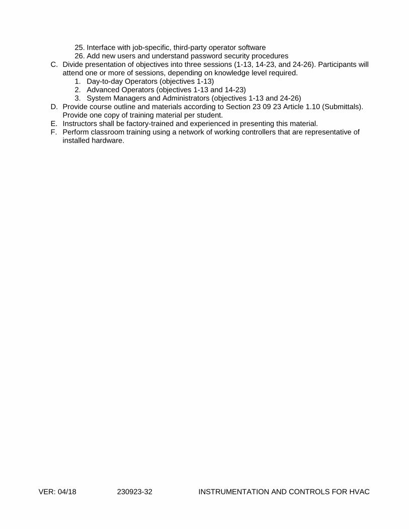
VER: 04/18 230923-32 INSTRUMENTATION AND CONTROLS FOR HVAC
25. Interface with job-specific, third-party operator software 26. Add new users and understand password security procedures
C. Divide presentation of objectives into three sessions (1-13, 14-23, and 24-26). Participants will attend one or more of sessions, depending on knowledge level required.
1. Day-to-day Operators (objectives 1-13) 2. Advanced Operators (objectives 1-13 and 14-23) 3. System Managers and Administrators (objectives 1-13 and 24-26)
D. Provide course outline and materials according to Section 23 09 23 Article 1.10 (Submittals). Provide one copy of training material per student.
E. Instructors shall be factory-trained and experienced in presenting this material. F. Perform classroom training using a network of working controllers that are representative of
installed hardware.

VER: 04/18 230923 Appendix A-1 INSTRUMENTATION AND CONTROLS FOR HVAC
APPENDIX A – NAMING CONVENTIONS
1.1 Abbreviations
A - Alarm
AC - Air Conditioning
ACLG - Actual Cooling
ACU - Air Conditioning Unit
AHTG - Actual Heating
AHU - Air Handling Unit
AI - Analog Input
AO - Analog Output
APPRCH - Approach
AUTO - Automatic
AUX - Auxiliary
BI - Binary Input
BLDG - Building
BO - Binary Output
BSP - Building Static Pressure
BST - Booster
BYP - Bypass
C – Command
CAL - Calibration
CD-T = Cold Deck temperature
CHLR - Chiller
CHW - Chilled Water
CHWE – Chilled Water Entering
CHWL - Chilled Water Leaving
CHWP - Chilled Water Pump
CHWR - Chilled Water Return
CHWS - Chilled Water Supply
CLG - Cooling
COMP - Compressor
COND - Condenser
CRAC - Computer Room Air Conditioner
CT - Cooling Tower
CTF – Cooling Tower Fan
CTL - Control
CW - Condenser Water
CWP - Condenser Water Pump
CWR - Condenser Water Return
CWS - Condenser Water Supply

VER: 04/18 230923 Appendix A-2 INSTRUMENTATION AND CONTROLS FOR HVAC
DA – Discharge Air
DA-T = Discharge Air Temperature
DA-P - Discharge Air Static Pressure
DB - Deadband
DPR – Damper
DP - Differential Pressure
EA - Exhaust Air
ECON - Economizer
EF - Exhaust Fan
EFFCLG – Effective Cooling
EFFHTG – Effective Heating
EFFOCC – Effective Occupancy
ENA - Enable
EVAP –Evaporator
EWT – Entering Water Temperature
FBD - Face/Bypass dampers
FCU - Fan Coil Unit
F - Flow
FLTR - Filter
FVAV - Fan Powered VAV Terminal Unit
FWD - Forward
GEN - Generator
HD-T = Hot Deck Temperature
HHP – High Head Pressure
HOA - Hand / Off / Auto
HP - Heat Pump
HRU - Heat Recovery Unit
HT – High Temperature
HTG – Heating
HUM - Humidifier
HW - Hot Water
HWP - Hot Water Pump
HWR - Hot Water Return
HWS - Hot Water Supply
HX - Heat Exchanger
ISO - Isolation
KWH - Kilowatt Hour
LSP – Low Suction Pressure
LVL – Level

VER: 04/18 230923 Appendix A-3 INSTRUMENTATION AND CONTROLS FOR HVAC
LWT – Leaving Water Temperature
MA-T = Mixed Air Temperature
MAX - Maximum
MAXPOS - Maximum Position
MIN - Minimum
MINPOS - Minimum Position
MISC – Miscellaneous
MOT – Minimum On Time
NC - Normally Closed
NO - Normally Open
O - Output
OA - Outdoor Air
OAD - Outside Air Damper
OCCCLG - Occupied Cooling
OCCHTG - Occupied Heating
OL - Overload
P - Pressure
PB - Proportional Band
PCHW – Primary Chilled Water
PD – Pressure Differential
PIU - Powered Induction Unit
RA - Return Air
REV - Reverse
RF - Return Fan
RH - Relative Humidity
RLF - Relief Fan
RM – Room
RS - Reset
RTU - Roof-top Unit
S – Status
SA – Supply Air
SC – Short Cycle
SCHW – Secondary Chilled Water
SDWN - Shutdown
SF - Supply Fan
SMKDET – Smoke Detector
SP – Setpoint
SPD – Speed
SYS - System

VER: 04/18 230923 Appendix A-4 INSTRUMENTATION AND CONTROLS FOR HVAC
T – Temperature
TO – Thermal Overload
TOCC – Temporary Occupancy
UFSP – Under Floor Static Pressure
UH - Unit Heater
UNOCC - Unoccupied
UPS - Uninterruptable Power Supply
UV - Unit Ventilator
VLV - Valve
VAV - Variable Air Volume
VFD - Variable Frequency (Speed) Drive
VIB - Vibration
VVTU - Variable Volume Terminal Unit
W/ - with
W/O - without
W/C - Warm/Cool
WB - Wet Bulb
WSHP - Water Source Heat Pump
WUF – Water Under Floor
ZN - Zone
ZN-H = Zone Humidity
ZN-T = Zone Temperature

VER: 04/18 230923 Appendix A-5 INSTRUMENTATION AND CONTROLS FOR HVAC
1.2 SITE LOCATION ABBREVIATIONS
16 – 16th Street Facility
27 – 27th Street Facility
CU – Credit Union Building
EV – East Valley Service Center
FT – Foothills Training Center
IS – Information Services Building
PA – Project Administration Building
PB – Papago Buttes Facility
PC – Pinal Customer Center
PO – Power Operations Building
SS – Southside Water Facility
TE – Tempe Service Center
WV – West Valley Service Center
XC – Crosscut Facility

VER: 04/18 230923 Appendix A-6 INSTRUMENTATION AND CONTROLS FOR HVAC
1.3 Naming Conventions
SITE CONTROLLER NAMING:
NAE## SITE NAME (LISTED IN OBJECT NAME)
NOTE: The object description will contain site/application information
EXAMPLE:
NAE10 Tempe Service Center
Object Description = “Tempe Service Center Bldg. 3”
TRUNK NAMES:
MSTP-1 OR MSTP-2
N2-1 OR N2-2
DEVICE NAMES:
EXAMPLE: FCU’S
2701FCU101 1-13N7E OFFICE
27 (SITE NAME)
01 (BLDG#)
FCU101 (DEVICE OR SYSTEM NAME)
1-13N7E (LOCATION COORDINATES)
OFFICE (SPACE TYPE)
NOTE: The device object description should include the asset Maximo number and the location
coordinates (when applicable).
POINT NAMES:
EXAMPLE:
2701FCU101 1-13N7E OFFICE DA-T
27 (SITE NAME)
01 (BLDG#)
FCU101 (DEVICE OR SYSTEM NAME)
1-13N7E (LOCATION COORDINATES)
OFFICE (SPACE TYPE)
DA-T (DISCHARGE AIR TEMPERATURE)
NOTE: The device object description should include the asset Maximo number and the location
coordinates (when applicable).
Label and Set 10 minute trends, repository enabled on Analog Input, Output and Analog Data Points:
ZN-T, DA-T, SA-F, SA-F-SP, DMP-O, CLG-O, HTG-O, etc.
Label and Set COS trends, repository enabled on Binary Input, Output and Binary Data Points:
SF-C, SF-S, HTG1-C, HTG2-C, etc.

VER: 04/18 230923 Appendix A-7 INSTRUMENTATION AND CONTROLS FOR HVAC
1.4 Typical Points Included by Equipment Type
This is a list of typical points to be included in the Metasys Facility Folders for various types of
equipment. Please confirm these for each project with the Owner.
A. Terminal Unit, Variable Volume, Cooling Only
ZN-T Zone Temperature, deg F
CLGOCC-SP Cooling Occupied Temperature Setpoint, deg F
SA-F Supply Air Flow Rate, cfm
SA-F-SP Supply Air Flow Rate Setpoint, cfm
CLG-MIN-F Cooling Minimum Air Flow Rate, cfm
CLG-MAX-F Cooling Maximum Air Flow Rate, cfm
DPR-O Supply Air Damper Output, %
CLG-O Cooling Output, %
B. Terminal Unit, Variable Volume, Cooling & Heating
ZN-T Zone Temperature, deg F
CLGOCC-SP Cooling Occupied Temperature Setpoint, deg F
HTGOCC-SP Heating Occupied Temperature Setpoint, deg F
SA-F Supply Air Flow Rate, cfm
SA-F-SP Supply Air Flow Rate Setpoint, cfm
HTG-MIN-F Heating Minimum Air Flow Rate, cfm
CLG-MIN-F Cooling Minimum Air Flow Rate, cfm
CLG-MAX-F Cooling Maximum Air Flow Rate, cfm
DPR-O Supply Air Damper Output, %
CLG-O Cooling Output, %
DA-T Discharge Air Temperature, deg F
HTG-O Heating Output, %
HTG1-C Heating Stage 1 Command, On/Off
HTG2-C Heating Stage 2 Command, On/Off
C. Terminal Unit, Fan Powered, Variable Volume, Cooling & Heating
ZN-T Zone Temperature, deg F
CLGOCC-SP Cooling Occupied Temperature Setpoint, deg F
HTGOCC-SP Heating Occupied Temperature Setpoint, deg F
SA-F Supply Air Flow Rate, cfm
SA-F-SP Supply Air Flow Rate Setpoint, cfm
HTG-MIN-F Heating Minimum Air Flow Rate, cfm
CLG-MIN-F Cooling Minimum Air Flow Rate, cfm
CLG-MAX-F Cooling Maximum Air Flow Rate, cfm
DPR-O Damper Output, %

VER: 04/18 230923 Appendix A-8 INSTRUMENTATION AND CONTROLS FOR HVAC
CLG-O Cooling Output, %
DA-T Discharge Air Temperature, deg F
SF-C Supply Fan Command, On/Off
SF-S Supply Fan Status, On/Off
HTG-O Heating Output, %
HTG1-C Heating Stage 1 Command, On/Off
HTG2-C Heating Stage 2 Command, On/Off
D. Fan Coil Unit, Cooling Only
ZN-T Zone Temperature, deg F
CLGOCC-SP Cooling Occupied Temperature Setpoint, deg F
CLG-O Cooling Output, %
DA-T Discharge Air Temperature, deg F
SF-C Supply Fan Command, On/Off
SF-S Supply Fan Status, On/Off
E. Fan Coil Unit, Heating and Cooling
ZN-T Zone Temperature, deg F
CLGOCC-SP Cooling Occupied Temperature Setpoint, deg F
HTGOCC-SP Heating Occupied Temperature Setpoint, deg F
CLG-O Cooling Output, %
DA-T Discharge Air Temperature, deg F
SF-C Supply Fan Command, On/Off
SF-S Supply Fan Status, On/Off
HTG-O Heating Output, %
F. Computer Room Air Conditioning (CRAC) Unit
UNIT-S Unit Status, On/Off
UNIT-A Unit Alarm, On/Off
SMKDET-A Smoke Detected, Normal/Alarm
WUF-A Water Under Floor Alarm, Normal/Alarm
ZN-T Zone Temperature, deg F
RA-T Return Air Temperature, deg F
SF-O Supply Fan Output, %
SF-S Supply Fan Status, On/Off
CLG-O Cooling Output, %
RH-SP Relative Humidity Setpoint, %RH
RA-RH Return Air Relative Humidity, %RH
HUM-O Humidifier Output, %
COMP1-LSP Compressor 1 Low Suction Pressure, Normal/Alarm

VER: 04/18 230923 Appendix A-9 INSTRUMENTATION AND CONTROLS FOR HVAC
COMP1-HHP Compressor 1 High Head Pressure, Normal/Alarm
COMP1-TO Compressor 1 Thermal Overload
COMP1-PD Compressor 1 Pump Down Issue
COMP1-SC Compressor 1 Short Cycle (Compressors)
COMP2-LSP Compressor 2 Low Suction Pressure, Normal/Alarm
COMP2-HHP Compressor 2 High Head Pressure, Normal/Alarm
COMP2-TO Compressor 2 Thermal Overload
COMP2-PD Compressor 2 Pump Down Issue
COMP2-SC Compressor 2 Short Cycle (Compressors)
G. Direct Expansion System, Cooling Only
SF-C Fan Command, On/Off
SF-S Fan Status, On/Off
ZN-T Zone Temperature, deg F
CLGOCC-SP Cooling Occupied Temperature Setpoint, deg F
CLG1-S Cooling Stage 1 Status, On/Off
CLG2-S Cooling Stage 2 Status, On/Off
H. Direct Expansion System, Cooling w/Electric Heat
SF-C Fan Command, On/Off
SF-S Fan Status, On/Off
ZN-T Zone Temperature, deg F
CLGOCC-SP Cooling Occupied Setpoint, deg F
HTGOCC-SP Heating Occupied Setpoint, deg F
CLG1-S Cooling Stage 1 Status, On/Off
CLG2-S Cooling Stage 2 Status, On/Off
HTG1-S Heating Stage 1 Status, On/Off
HTG2-S Heating Stage 2 Status, On/Off
I. Direct Expansion System, Heat Pump
SF-C Fan Command, On/Off
SF-S Fan Status, On/Off
ZN-T Zone Temperature, deg F
CLGOCC-SP Cooling Occupied Setpoint, deg F
HTGOCC-SP Heating Occupied Setpoint, deg F
CLG1-S Cooling Stage 1 Status, On/Off
CLG2-S Cooling Stage 2 Status, On/Off
HTG1-S Heating Stage 1 Status, On/Off
HTG2-S Heating Stage 2 Status, On/Off

VER: 04/18 230923 Appendix A-10 INSTRUMENTATION AND CONTROLS FOR HVAC
J. Air Handling Unit
SF-C Supply Fan Command, On/Off
SF-S Supply Fan Status, On/Off
SF-SPD Supply Fan Speed, %
RF-C Return Fan Command, On/Off
RF-S Return Fan Status, On/Off
RF-SPD Return Fan Speed, %
DUCT-P-SP Duct Static Pressure Setpoint, in. w.c.
DUCT-P Duct Static Pressure, in. w.c.
DAT-SP Discharge Air Temperature Setpoint, deg F
DA-T Discharge Air Temperature, deg F
RA-T Return Air Temperature, deg F
MA-T Mixed Air Temperature, deg F
0SA-T Outside Air Temperature, deg F
CLG-VLV-O Cooling Valve Output, %
OA-DMP-SP Outside Air Damper Setpoint, %
OA-DMP-O Outside Air Damper Output, %
SA-F Supply Air Flow Rate, cfm
RA-F Return Air Flow Rate, cfm
SMKDET-S Duct Smoke Detector Status, On/Off
K. Chiller, Air Cooled
UNIT-C Chiller Command, On/Off
UNIT-S Chiller Status, On/Off
Comp-S Compressor Status, On/Off
ISOVLV-C Chiller Isolation Valve Command
ISOVLV-S Chiller Isolation Valve Status
CHWS-SP CHWS Temperature Setpoint, deg F
CHWS-RS-LT-SP CHWS Temperature Reset: Low OA Temperature, deg F
CHWS-RS-LT CHWS Temperature@ Low OA Reset, deg F
CHWS-RS-HT-SP CHWS Temperature Reset: High OA Temperature, deg F
CHWS-RS-HT CHWS Temperature@ High OA Reset, deg F
SYS1SUCT-P System 1 Suction Pressure
SYS1DIS-P System 1 Discharge Pressure
SYS1RUNTIME System 1 Runtime
SYS1COMP1-R System 1 Compressor 1 Run
SYS1COMP2-R System 1 Compressor 2 Run
SYS1LLSV System 1 Liquid Line Solenoid Valve
SYS1HGBYPV System 1 Hot Gas Bypass Valve
SYS1FAULT System 1 Fault
SYS1ALARM System 1 Alarm
HOA Chiller HOA & Reset Toggle after event

VER: 04/18 230923 Appendix A-11 INSTRUMENTATION AND CONTROLS FOR HVAC
S-A Chiller Status Alarm, On/Off
ISOVLV-A Chiller Isolation Valve Alarm, On/Off
CHWS-T Chiller CHW Supply Temperature, deg F
CHWR-T Chiller CHW Return Temperature, deg F
L. Chiller, Water Cooled
UNIT-C Chiller Command, On/Off
UNIT-S Chiller Status, On/Off
Comp-S Compressor Status, On/Off
ISOVLV-C Chiller Isolation Valve Command
ISOVLV-S Chiller Isolation Valve Status
CHWS-SP CHWS Temperature Setpoint, deg F
CHWS-RS-LT-SP CHWS Temperature Reset: Low OA Temperature, deg F
CHWS-RS-LT CHWS Temperature@ Low OA Reset, deg F
CHWS-RS-HT-SP CHWS Temperature Reset: High OA Temperature, deg F
CHWS-RS-HT CHWS Temperature@ High OA Reset, deg F
PD-TIME Pump-Down Time
MOT Chiller Minimum On Time
HOA Chiller HOA & Reset Toggle after event
S-A Chiller Status Alarm, On/Off
ISOVLV-A Chiller Isolation Valve Alarm, On/Off
CHWS-T Chiller CHW Supply Temperature, deg F
CHWR-T Chiller CHW Return Temperature, deg F
CWR-T Chiller CW Return Temperature, deg F
M. Cooling Tower
UNIT-C Cooling Tower Command, On/Off
UNIT-S Cooling Tower Status, On/Off
UNIT-O Cooling Tower Output, %
CTF-SPD Cooling Tower Fan Speed, %
APPRCH-T Cooling Tower Approach Temperature, deg F
ISOVLV-C Cooling Tower Isolation Valve Command
ISOVLV-S Cooling Tower Isolation Valve Status
ISOVLV-A Cooling Tower Isolation Valve Alarm, On/Off
EWT Cooling Tower Entering Water Temperature, deg F
LWT Cooling Tower Leaving Water Temperature, deg F
LWT-SP CT Leaving Water Temperature Setpoint, deg F
BYPVLV-0 Cooling Tower Bypass Valve Output, %