section 2 terms and definitions
TRANSCRIPT

Section 2
Terms and Definitions
10

Rev 1 January 2009 Terms and Definitions
Copyright TWI Ltd 2009
Note:The following definitions are taken from BS 499-1:1991 ‘Welding terms and symbols – Glossary for welding, brazing and thermal cutting’.
Brazing
A process of joining generally applied to metals in which, during or after heating, molten filler metal is drawn into or retained in the space between closely adjacent surfaces of the parts to be joined by capillary attraction. In
general, the melting point of the filler metal is above 450 C but always below the melting temperature of the parent material.
Braze welding
The joining of metals using a technique similar to fusion welding and a filler metal with a lower melting point than the parent metal, but neither using capillary action as in brazing nor intentionally melting the parent metal.
Joint
A connection where the individual components, suitably prepared and assembled, are joined by welding or brazing.
Weld
A union of pieces of metal made by welding.
Welding
An operation in which two or more parts are united by means of heat or pressure or both, in such a way that there is continuity in the nature of the metal between these parts.
.
11
Rev 1 January 2009 Terms and Definitions
Copyright TWI Ltd 2009
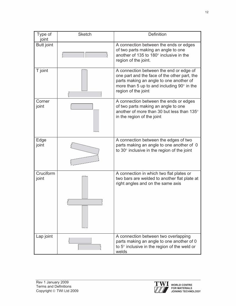
Type of joint
Sketch Definition
Butt joint A connection between the ends or edges of two parts making an angle to one
another of 135 to 180 inclusive in the region of the joint.
T joint A connection between the end or edge of one part and the face of the other part, the parts making an angle to one another of
more than 5 up to and including 90 in the region of the joint
Corner joint
A connection between the ends or edges of two parts making an angle to one
another of more than 30 but less than 135in the region of the joint
Edge joint
A connection between the edges of two parts making an angle to one another of 0
to 30 inclusive in the region of the joint
Cruciform joint
A connection in which two flat plates or two bars are welded to another flat plate at right angles and on the same axis
Lap joint A connection between two overlapping parts making an angle to one another of 0
to 5 inclusive in the region of the weld or welds
12
Rev 1 January 2009 Terms and Definitions
Copyright TWI Ltd 2009
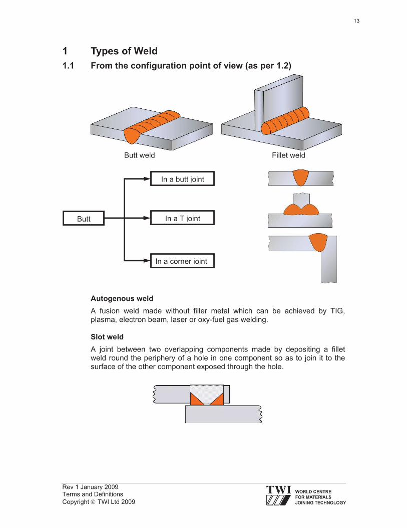
1 Types of Weld
1.1 From the configuration point of view (as per 1.2)
Butt weld Fillet weld
Autogenous weld
A fusion weld made without filler metal which can be achieved by TIG, plasma, electron beam, laser or oxy-fuel gas welding.
Slot weld
A joint between two overlapping components made by depositing a fillet weld round the periphery of a hole in one component so as to join it to the surface of the other component exposed through the hole.
Butt
In a butt joint
In a T joint
In a corner joint
13

Rev 1 January 2009 Terms and Definitions
Copyright TWI Ltd 2009
Plug weld
A weld made by filling a hole in one component of a workpiece with filler metal so as to join it to the surface of an overlapping component exposed through the hole (the hole can be circular or oval).
1.2 From the penetration point of view
Full penetration weld
A welded joint where the weld metal fully penetrates the joint with complete root fusion. In US the preferred term is complete joint penetration weld (CJP) (see AWS D1.1.).
Partial penetration weld:
A welded joint without full penetration. In US the preferred term is partial joint penetration weld (PJP).
2 Types of Joints (see BS EN ISO 15607)
Homogeneous: Welded joint in which the weld metal and parent material have no significant differences in mechanical properties and/or chemical composition. Example: Two carbon steel plates welded with a matching carbon steel electrode.
Heterogeneous: Welded joint in which the weld metal and parent material have significant differences in mechanical properties and/or chemical composition. Example: A repair weld of a cast iron item performed with a nickel-based electrode.
Dissimilar: Welded joint in which the parent materials have significant differences in mechanical properties and/or chemical composition. Example: A carbon steel lifting lug welded onto an austenitic stainless steel pressure vessel.
14
Rev 1 January 2009 Terms and Definitions
Copyright TWI Ltd 2009
3 Features of the Completed Weld
Parent metal: Metal to be joined or surfaced by welding, braze welding or brazing.
Filler metal: Metal added during welding, braze welding, brazing or surfacing.
Weld metal: All metal melted during the making of a weld and retained in the weld.
Heat-affected zone (HAZ): The part of the parent metal that is metallurgically affected by the heat of welding or thermal cutting, but not melted.
Fusion line: The boundary between the weld metal and the HAZ in a fusion weld. This is a non-standard term for weld junction.
Weld zone: The zone containing the weld metal and the HAZ.
Weld face: The surface of a fusion weld exposed on the side from which the weld has been made.
Root: The zone on the side of the first run furthest from the welder.
Toe: The boundary between a weld face and the parent metal or between runs. This is a very important feature of a weld since toes are points of high stress concentration and often they are initiation points for different types of cracks (eg fatigue cracks, cold cracks). In order to reduce the stress concentration, toes must blend smoothly into the parent metal surface.
Excess weld metal: Weld metal lying outside the plane joining the toes. Other non-standard terms for this feature: Reinforcement, overfill.
15

Rev 1 January 2009 Terms and Definitions
Copyright TWI Ltd 2009
Root
Parent metal
Weld metal
HAZ
Weld zone
Fusion line
Weld face Toe
Parent metal
Excess weld metal
Excess weld metal
Fusion line
Weld metal
Root
Parent metal
HAZ
Weld zone
Weld face
Toe
Parent metal
Excess weld metal
16
Rev 1 January 2009 Terms and Definitions
Copyright TWI Ltd 2009
4 Weld Preparation
A preparation for making a connection where the individual components, suitably prepared and assembled, are joined by welding or brazing.
4.1 Features of the weld preparation
Angle of bevel
The angle at which the edge of a component is prepared for making a weld.
For an MMA weld on carbon steel plates, the angle is:
25-30 for a V preparation.
8-12o for a U preparation.
40-50o for a single bevel preparation.
10-20o for a J preparation.
Included angle
The angle between the planes of the fusion faces of parts to be welded. In the case of single V or U and double V or U this angle is twice the bevel angle. In the case of single or double bevel, single or double J bevel, the included angle is equal to the bevel angle.
Root face
The portion of a fusion face at the root that is not bevelled or grooved. It’s value depends on the welding process used, parent material to be welded and application; for a full penetration weld on carbon steel plates, it has a value between 1-2mm (for the common welding processes).
Gap
The minimum distance at any cross section between edges, ends or surfaces to be joined. Its value depends on the welding process used and application; for a full penetration weld on carbon steel plates, it has a value between 1-4mm.
Root radius
The radius of the curved portion of the fusion face in a component prepared for a single J or U, double J or U weld. In case of MMA, MIG/MAG and oxy-fuel gas welding on carbon steel plates, the root radius has a value of 6mm for single and double U preparations and 8mm for single and double J preparations.
Land
The straight portion of a fusion face between the root face and the curved part of a J or U preparation, can be 0. Usually present in weld preparations for MIG welding of aluminium alloys.
17
Rev 1 January 2009 Terms and Definitions
Copyright TWI Ltd 2009
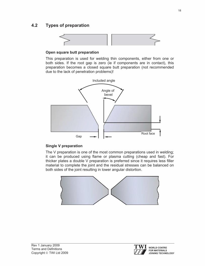
4.2 Types of preparation
Open square butt preparation
This preparation is used for welding thin components, either from one or both sides. If the root gap is zero (ie if components are in contact), this preparation becomes a closed square butt preparation (not recommended due to the lack of penetration problems)!
Single V preparation
The V preparation is one of the most common preparations used in welding; it can be produced using flame or plasma cutting (cheap and fast). For thicker plates a double V preparation is preferred since it requires less filler material to complete the joint and the residual stresses can be balanced on both sides of the joint resulting in lower angular distortion.
Angle of bevel
Included angle
GapRoot face
18

Rev 1 January 2009 Terms and Definitions
Copyright TWI Ltd 2009
Double V preparation
The depth of preparation can be the same on both sides (symmetric double V preparation) or can be deeper on one side compared with the opposite side (asymmetric double V preparation). Usually, in this situation the depth of preparation is distributed as 2/3 of the thickness of the plate on the first side with the remaining 1/3 on the backside. This asymmetric preparation allows for a balanced welding sequence with root back gouging, giving lower angular distortions. Whilst single V preparation allows welding from one side, double V preparation requires access to both sides (the same applies for all double side preparations).
Single U preparation
U preparation can be produced only by machining (slow and expensive). However, tighter tolerances obtained in this case provide for a better fit-up than in the case of V preparations. Usually it is applied to thicker plates compared with single V preparation as it requires less filler material to complete the joint and this leads to lower residual stresses and distortions. Similar to the V preparation, in the case of very thick sections a double U preparation can be used.
Double U preparation
Usually this type of preparation does not require a land (exception: aluminium alloys).
Included angle
Angle ofbevel
Root
radius
Gap
Land
Root face
19
Rev 1 January 2009 Terms and Definitions
Copyright TWI Ltd 2009
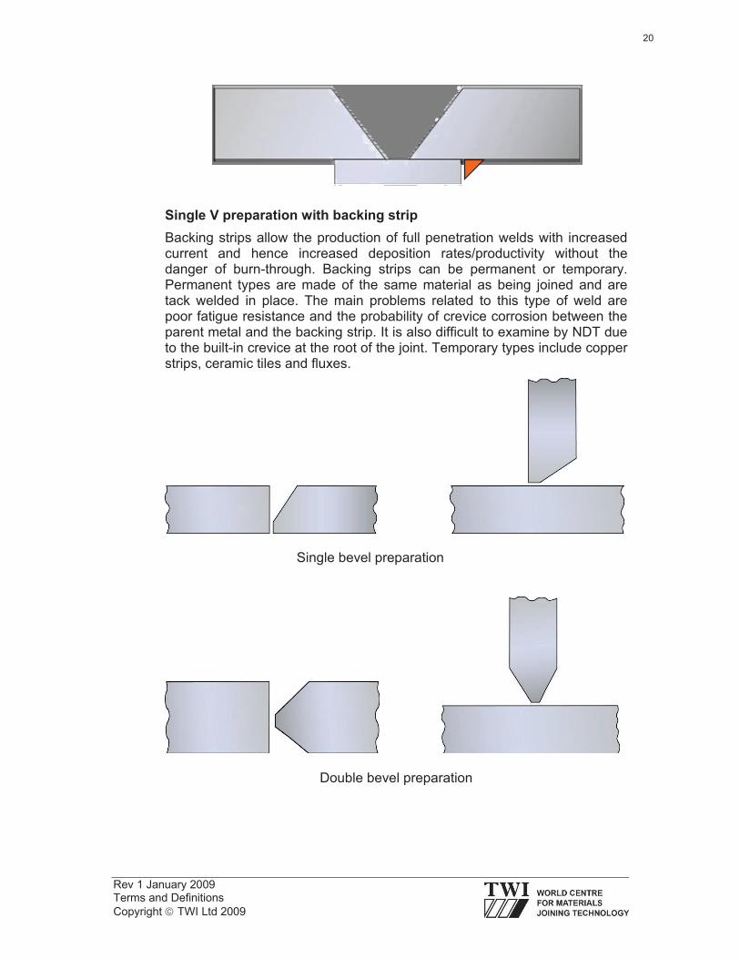
Single V preparation with backing strip
Backing strips allow the production of full penetration welds with increased current and hence increased deposition rates/productivity without the danger of burn-through. Backing strips can be permanent or temporary. Permanent types are made of the same material as being joined and are tack welded in place. The main problems related to this type of weld are poor fatigue resistance and the probability of crevice corrosion between the parent metal and the backing strip. It is also difficult to examine by NDT due to the built-in crevice at the root of the joint. Temporary types include copper strips, ceramic tiles and fluxes.
Single bevel preparation
Double bevel preparation
20
Rev 1 January 2009 Terms and Definitions
Copyright TWI Ltd 2009
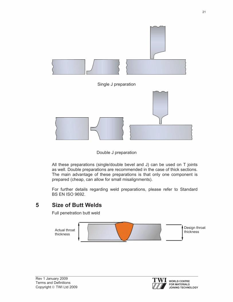
Single J preparation
Double J preparation
All these preparations (single/double bevel and J) can be used on T joints as well. Double preparations are recommended in the case of thick sections. The main advantage of these preparations is that only one component is prepared (cheap, can allow for small misalignments).
For further details regarding weld preparations, please refer to Standard BS EN ISO 9692.
5 Size of Butt Welds
Full penetration butt weld
Design throat thickness
Actual throat thickness
21

Rev 1 January 2009 Terms and Definitions
Copyright TWI Ltd 2009
Partial penetration butt weld
As a general rule:
Actual throat thickness = design throat thickness + excess weld metal .
Full penetration butt weld ground flush
Butt weld between two plates of different thickness
Run (pass): The metal melted or deposited during one passage of an electrode, torch or blowpipe.
Single run weld Multi run weld
Layer: A stratum of weld metal consisting of one or more runs.
Actual throat thickness = design throatthickness
Design throat thickness
Actual throat thickness
Design throat thickness = thickness of the thinner plate
Actual throat thickness = maximum thickness through the joint
22
Rev 1 January 2009 Terms and Definitions
Copyright TWI Ltd 2009
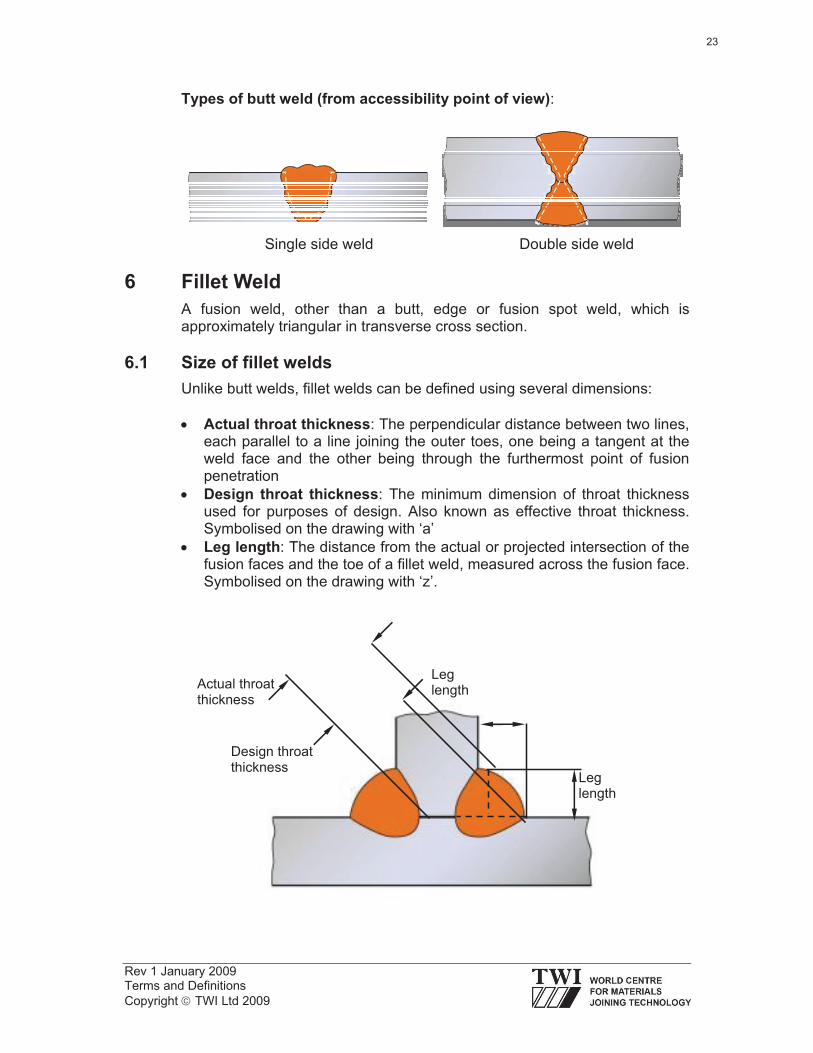
Types of butt weld (from accessibility point of view):
Single side weld Double side weld
6 Fillet Weld
A fusion weld, other than a butt, edge or fusion spot weld, which is approximately triangular in transverse cross section.
6.1 Size of fillet welds
Unlike butt welds, fillet welds can be defined using several dimensions:
Actual throat thickness: The perpendicular distance between two lines, each parallel to a line joining the outer toes, one being a tangent at the weld face and the other being through the furthermost point of fusion penetration
Design throat thickness: The minimum dimension of throat thickness used for purposes of design. Also known as effective throat thickness. Symbolised on the drawing with ‘a’
Leg length: The distance from the actual or projected intersection of the fusion faces and the toe of a fillet weld, measured across the fusion face. Symbolised on the drawing with ‘z’.
Actual throatthickness
Design throatthickness
Leglength
Leglength
23

Rev 1 January 2009 Terms and Definitions
Copyright TWI Ltd 2009
6.2 Shape of fillet welds
Mitre fillet weld: A flat face fillet weld in which the leg lengths are equal within the agreed tolerance. The cross section area of this type of weld can be considered to be a right angle isosceles triangle with a design throat thickness ‘a’ and leg length ‘z’. The relation between design throat thickness and leg length is:
a = 0.707 z . or z = 1.41 a .
Convex fillet weld: A fillet weld in which the weld face is convex. The above relation between the leg length and the design throat thickness written for mitre fillet welds is also valid for this type of weld. Since there is excess weld metal present in this case, the actual throat thickness is bigger than the design throat thickness.
Concave fillet weld: A fillet weld in which the weld face is concave. The relation between the leg length and the design throat thickness specified for mitre fillet welds is not valid for this type of weld. Also, the design throat thickness is equal to the actual throat thickness. Due to the smooth blending between the weld face and the surrounding parent material, the stress concentration effect at the toes of the weld is reduced compared with the previous type. This is why this type of weld is highly desired in case of applications subjected to cyclic loads where fatigue phenomena might be a major cause for failure.
24

Rev 1 January 2009 Terms and Definitions
Copyright TWI Ltd 2009
Asymmetrical fillet weld: A fillet weld in which the vertical leg length is not equal to the horizontal leg length. The relation between the leg length and design throat thickness is no longer valid for this type of weld because the cross section is not an isosceles triangle.
Deep penetration fillet weld: A fillet weld with a deeper than normal penetration. It is produced using high heat input welding processes (ie SAW or MAG with spray transfer). This type of weld uses the benefits of greater arc penetration to obtain the required throat thickness whilst reducing the amount of deposited metal needed, thus leading to a reduction in residual stress level. In order to produce a consistent and constant penetration, the travel speed must be kept constant, at a high value. As a consequence, this type of weld is usually produced using mechanised or automatic welding processes. Also, the high depth-to-width ratio increases the probability of solidification centreline cracking. In order to differentiate this type of weld from the previous types, the throat thickness is symbolised with ‘s’ instead of ‘a’.
Throat size
Vertical leg size
Horizontalleg size
25

Rev 1 January 2009 Terms and Definitions
Copyright TWI Ltd 2009
6.3 Compound of butt and fillet welds
This is a combination of butt and fillet welds used for T joints with full or partial penetration or butt joints between two plates with different thickness. Fillet welds added on top of the groove welds improve the blending of the weld face towards the parent metal surface and reduce the stress concentration at the toes of the weld.
Double bevel compound weld
7 Welding Position, Weld Slope and Weld Rotation
Welding position: The orientation of a weld expressed in terms of working position, weld slope and weld rotation (for further details, please see ISO 6947).
Weld slope: The angle between root line and the positive X axis of the horizontal reference plane, measured in mathematically positive direction (ie counter-clockwise).
Weld rotation: The angle between the centreline of the weld and the positive Z axis or a line parallel to the Y axis, measured in the mathematically positive direction (ie counter-clockwise) in the plane of the transverse cross section of the weld in question.
26
Rev 1 January 2009 Terms and Definitions
Copyright TWI Ltd 2009
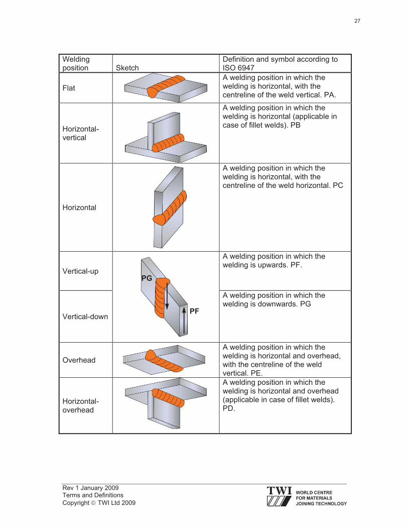
Welding position Sketch
Definition and symbol according to ISO 6947
Flat
A welding position in which the welding is horizontal, with the centreline of the weld vertical. PA.
Horizontal-vertical
A welding position in which the welding is horizontal (applicable in case of fillet welds). PB
Horizontal
A welding position in which the welding is horizontal, with the centreline of the weld horizontal. PC
Vertical-up
A welding position in which the welding is upwards. PF.
Vertical-down
A welding position in which the welding is downwards. PG
Overhead
A welding position in which the welding is horizontal and overhead, with the centreline of the weld vertical. PE.
Horizontal-overhead
A welding position in which the welding is horizontal and overhead (applicable in case of fillet welds). PD.
PF
PG
27
Rev 1 January 2009 Terms and Definitions
Copyright TWI Ltd 2009
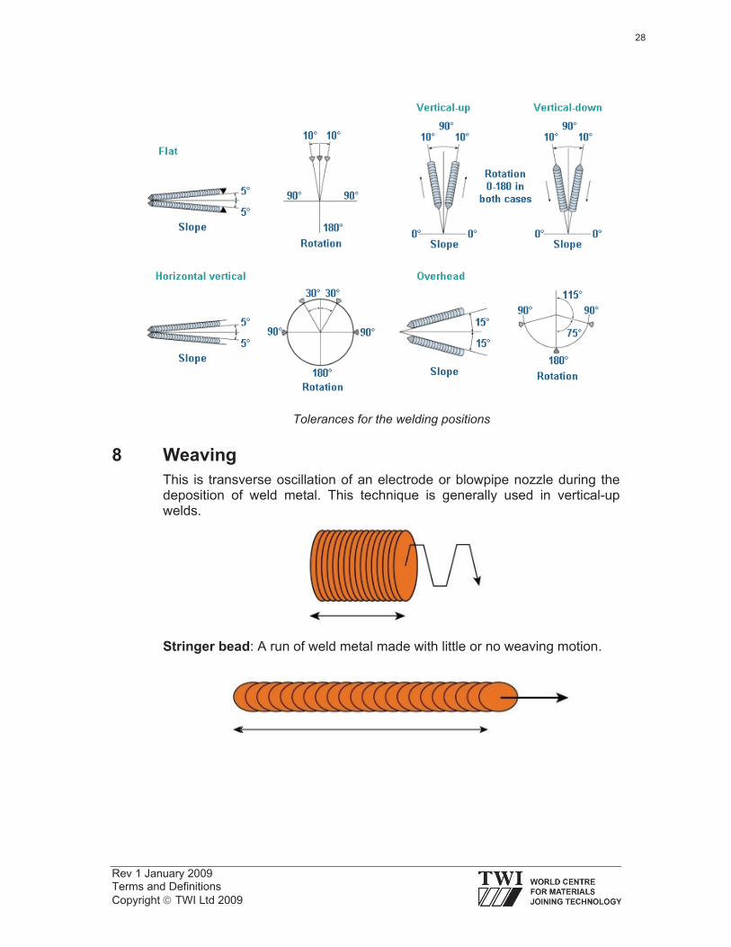
Tolerances for the welding positions
8 Weaving
This is transverse oscillation of an electrode or blowpipe nozzle during the deposition of weld metal. This technique is generally used in vertical-up welds.
Stringer bead: A run of weld metal made with little or no weaving motion.
28