section 14 street lighting - home - transport · pdf filesection 14 street lighting ... 14.04...
TRANSCRIPT
SECTION 14 STREET LIGHTING
Standard Specification for Urban Infrastructure Works 14-1 Edition 1, Revision 0 / September 2002
CONTENTS
14 STREETLIGHTING 14-2
14.01 SCOPE 14-2
14.02 REFERENCE DOCUMENTS 14-2
14.03 MATERIALS 14-3 14.03.1 Conduits 14-3 14.03.2 Cabling 14-3
14.04 LIGHTING COLUMNS 14-3 14.04.1 Columns 14-3 14.04.2 Luminaires 14-5 14.04.3 Lamps 14-5 14.04.4 Photo Electric Cells (PE Cells) 14-5 14.04.5 Connections 14-6 14.04.6 Anchor Bolts 14-6
14.05 PLINTHS FOR LIGHT COLUMNS 14-6
14.06 ERECTION AND INSTALLATION 14-7 14.06.1 General 14-7 14.06.2 Earthing 14-7 14.06.3 Laying of Conduit 14-7 14.06.4 Cable Jointing Pits 14-8 14.06.5 Cabling 14-8 14.06.6 Installation of Lighting Columns 14-8 14.06.7 Commissioning and Testing 14-9 14.06.8 As-Installed Drawings 14-9
14.07 MEASUREMENT AND PAYMENT 14-10
14.08 SCHEDULE OF HOLD POINTS 14-11
SECTION 14 STREET LIGHTING
Standard Specification for Urban Infrastructure Works 14-2 Edition 1, Revision 0 / September 2002
14 STREETLIGHTING
14.01 SCOPE
This Specification sets out the minimum requirements for the supply, installation and commissioning of street lighting.
14.02 REFERENCE DOCUMENTS
The installation shall comply with the requirements and recommendations of the following standards, codes and regulations:
Australian Standards
AS 1158 Road Lighting
AS 1170.2 Minimum Design Loads on Srtructures - Wind Loads
AS 1214 Hot Dip Galvanised Coatings on Threaded Fasteners.
AS 1379 The Specification and Manufacture of Concrete.
AS 1538 Cold Formed Steel Structures Code
AS 1554.1 Structural Steel Welding - Welding of Steel Structures
AS 1627.1 Metal Finishing - Preparation and Pretreatment of Surfaces - Cleaning using Liquid Solvents and Alkaline Solutions
AS 1627.4 Metal Finishing - Preparation and Pretreatment of Surfaces - Abrasive Blast Cleaning.
AS 1650 Hot-Dipped Galvanised Coatings on Ferrous Articles
AS 1798 Lighting Poles and Bracket Arms
AS 2053 Non-Metallic Conduits and Fittings.
AS 3000 Electrical Installations - Buildings, Structures and Premises (known as the SAA Wiring Rules)
AS 3600 Concrete Structures
AS 3771 Road Lighting Luminaires with Integral Control Gear
AS 4100 Steel Structures
AS 4791 Hot-dip galvanised (zinc) coatings on ferrous open sections, applied by and inline process
AS 4792 Hot-dip galvanised (zinc) coatings on ferrous hollow sections, applied by a continuous or specialised process.
SECTION 14 STREET LIGHTING
Standard Specification for Urban Infrastructure Works 14-3 Edition 1, Revision 0 / September 2002
Authority Guidelines
Electrical Note 2 Electrical Installation of Street Lights, Traffic Lights, Combination Street and Traffic Lights and Public Area Lighting – ACT Government Planning and Land Management
COR 10.1.P1 Standard Conduit Technical Standards. Electricity Supply Authority Corporate Quality Procedure
14.03 MATERIALS
14.03.1 Conduits Conduits and conduit fittings for all cabling shall be Class 12 orange heavy duty rigid UPVC manufactured in accordance with AS 2053 and with solvent welded joints. All the conduits shall be of the sizes shown on the Drawings. Refer to Clause 14.06.3 for further requirements.
14.03.2 Cabling All cables shall be insulated and sheathed copper core cables. They shall have stranded copper conductors and shall be 4 core 16mm2 XLPE insulated, HDPE/PVC sheathed.
The number of circuits shall suit circuit loading and voltage drop considerations.
All cables shall have type V75 or V90 insulation.
The insulation of cables shall be coloured as shown in Table 14.1:
Table 14.1
Circuit Object Colour
Activities: Red, White, Blue Three phase circuits
Neutral: Black
Earth Conductors Green and Yellow
Refer to Clause 14.06.5 for further requirements.
14.04 LIGHTING COLUMNS
14.04.1 Columns Lighting columns shall be of the types, heights and outreaches as shown on the Drawings and shall confirm with the requirements of the relevant Australian Standard.
Lighting columns of 9m height or greater shall generally be of the frangible type, either slip base or impact absorbing as nominated on the Drawings.
Material shall be light gauge sheet steel or aluminium.
SECTION 14 STREET LIGHTING
Standard Specification for Urban Infrastructure Works 14-4 Edition 1, Revision 0 / September 2002
Allowance should be made for use with luminaires of approximately 12kg weight with a projected windage area of 0.2 square metres.
No permanent deformation or excessive vibration should occur under Wind Loading of up to 160km/hr for repeated gusts of up to 10 minutes duration.
The columns shall present a smooth appearance overall, with particular attention to the junction of the outreach and vertical sections.
Bends shall be a true radius, smooth and fee of kinks. The maximum deviation from the true shape at any point on the curve shall be checked by means of an internal template which allows for the diametrical taper of the outreach. When placed against the inside of the outreach any gaps between the outreach and the template shall not exceed 1% of the radius and the rate of gap increase shall not exceed 1 in 50.
Above the top of the base plate the columns shall be circular or multi sided in cross section throughout.
Any cross section measured normal to the axis of the vertical component shall have a tolerance of ± 2% of outside diameter. On the outreach this tolerance shall be ± 5% of the nominal outside diameter of the cross section at that point. Out of round in excess of this tolerance shall be grounds of rejection of the columns.
The methods of construction of the columns shall be such as to ensure that the vertical axis is perfectly straight and perpendicular to the base plate and the outreach is set in the plane of the vertical axis.
One side of the square base plate shall be at right angles to the outreach.
All burrs and blemishes shall be removed from the edges of the materials used. All sharp corners shall be removed from exposed edges, holes and openings provided for cables and for access to electrical equipment.
Welding shall be deposited in runs of sound, clean metal, free from slag inclusions, porosity and undercutting. Good fusion with parent material shall be obtained. Excess material shall be deposited and subsequently ground off flush to give a smooth surface and neat finish. All weld splatter shall be removed.
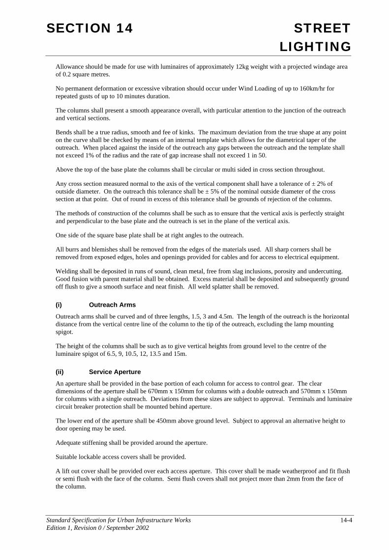
(i) Outreach Arms
Outreach arms shall be curved and of three lengths, 1.5, 3 and 4.5m. The length of the outreach is the horizontal distance from the vertical centre line of the column to the tip of the outreach, excluding the lamp mounting spigot.
The height of the columns shall be such as to give vertical heights from ground level to the centre of the luminaire spigot of 6.5, 9, 10.5, 12, 13.5 and 15m.
(ii) Service Aperture
An aperture shall be provided in the base portion of each column for access to control gear. The clear dimensions of the aperture shall be 670mm x 150mm for columns with a double outreach and 570mm x 150mm for columns with a single outreach. Deviations from these sizes are subject to approval. Terminals and luminaire circuit breaker protection shall be mounted behind aperture.
The lower end of the aperture shall be 450mm above ground level. Subject to approval an alternative height to door opening may be used.
Adequate stiffening shall be provided around the aperture.
Suitable lockable access covers shall be provided.
A lift out cover shall be provided over each access aperture. This cover shall be made weatherproof and fit flush or semi flush with the face of the column. Semi flush covers shall not project more than 2mm from the face of the column.

SECTION 14 STREET LIGHTING
Standard Specification for Urban Infrastructure Works 14-5 Edition 1, Revision 0 / September 2002
Prior to galvanising the surface of the steel shall be treated so that it is completely free from rust and mill scale and is suitable for hot dip galvanising.
The steel columns shall have a minimum thickness of 84 microns and a bright finished surface free from white rust and stains.
No further coating shall be applied to the external surface of the galvanised steel.
Assembly of lighting columns on the site may be permitted subject to approval by the Superintendent. The Contractor is to submit the detailed procedure proposed at least three (3) working days prior to commencement of work. Such site assembly shall be discontinued during adverse weather conditions that in the Superintendent’s opinion would be to the detriment of the completed column or at such other times as the Superintendent may direct.
The transport and storage of galvanised steel lighting columns shall be in accordance with Appendix G of AS 1650.
14.04.2 Luminaires Luminaires shall comply with the requirements of AS 3771. They shall be integral control gear type, power factor corrected to 0.9pf and shall have integral photo-electric cell control. Luminaires shall have individual circuit breaker protection inside the column.
14.04.3 Lamps Lamp types shall be as nominated on the drawings.
The lamps shall be suitable for use in the type of luminaire installed and shall have a guaranteed life as follows:
High pressure sodium and mercury vapour lamps - 4000 hours
400 Watt metal halide - 4000 hours
250 Watt and less metal halide lamps - 2000 hours
14.04.4 Photo Electric Cells (PE Cells) PE cells shall be integral with the luminaire. Where the installation is an extension to the existing and is centrally controlled, a bridging plug shall be provided in lieu of the PE cell.
PE cells shall have the following characteristics:
Rated voltage 220 – 270 Vac
Rated load 2 x 400W HPS
Lux on setting 20 Lux ± 10%
Enclosure IP65
Sensor Filtered silicon photodiode
Guarantee Period 5 years minimum
Power consumption Less than 0.5 Watt

SECTION 14 STREET LIGHTING
Standard Specification for Urban Infrastructure Works 14-6 Edition 1, Revision 0 / September 2002
14.04.5 Connections Main conductors shall loop in and out of large (suitable for 16mm2 conductors) terminal links provided in the base of columns. Provide disconnect plug and flex assemblies to standard Electricity Supply Authority detail for slip base columns.
Provide all necessary accessories for the above.
14.04.6 Anchor Bolts Anchor bolt assembilies for lighting columns shall be fabricated as shown on the drawings.
All welding shall be as shown on the drawings and shall be in accordance with the requirements of AS 1554.1 Category GP.
Prior to galvanising the surface shall be treated in accordance with AS 1627.1 and AS 1627.4 (Class 2½ Blast).
The anchor bolt assemblies shall be finished by the hot dip galvanising process in accordance with AS 1650 to provide a minimum thickness of 100 microns and a bright finished appearance free from all galvanising defects.
Bolts, nuts and washers shall be galvanised in accordance with AS 1214.
14.05 PLINTHS FOR LIGHT COLUMNS
The Contractor shall construct concrete plinths at the locations for light columns shown on the Drawings.
At light column locations on fills, the fill shall be widened locally as necessary to support the plinth.
Excavation for plinths shall be neatly cut from solid material. The ground conditions are to be confirmed as adequate in accordance with the design by a structural engineer where necessary. Excavated material shall be disposed of at locations acceptable to the Superintendent.
Plinths shall be constructed to the dimensions and with the embedments required.
Forms shall be so designed and constructed that they can be removed without damaging the concrete. They shall be built true to line and braced in a substantial and unyielding manner. They shall be mortar tight, and if necessary, timber forms shall be thoroughly soaked with water to close cracks due to shrinkage. The interior surface shall be lightly oiled to ensure the non-adhesion of the concrete, but care shall be taken not to stain the surface of concrete which will be exposed. The material used for forms shall be such as to give a smooth and even surface to the concrete.
The anchor bolt assembly shall be accurately placed and firmly supported.
Hold Point 14.1
Process Held: Placement of concrete for lighting columns plinth construction.
Submission Detail: A copy of the drawing(s) in each case certifying the plinth locations reference levels, dimensions and ground conditions are in accordance with the design and adequate for the installation.
Release of Hold Point: The Superintendent will consider the submitted drawings and certification prior to releasing of the Hold Point.

SECTION 14 STREET LIGHTING
Standard Specification for Urban Infrastructure Works 14-7 Edition 1, Revision 0 / September 2002
Concrete placed in plinths shall be normal class concrete with strength grade N20 in accordance with AS 3600 with 20 mm maximum nominal aggregate size.
If ready mixed concrete is used, the concrete shall be mixed and delivered in accordance with AS 1379.
The concrete shall be deposited in the forms, without segregation of the components. Concrete shall not be dropped freely from a height greater than 1 metre or be deposited in large quantities at any point and moved or worked along the forms. Care shall be taken to fill every part of the forms. The freshly placed concrete shall be compacted by approved vibrator units. Vibrators shall not be permitted to rest on anchorage bolt assemblies.
Exposed surfaces of the concrete shall be struck off and finished with a wooden float. All exposed edges shall be neatly rounded to a 5 mm radius.
14.06 ERECTION AND INSTALLATION
14.06.1 General The whole of the work shall be carried out in accordance with AS 3000 SAA Wiring Rules and the Service and Installation Rules of BEPCON.
The Contractor shall complete all necessary notices, pay all fees and charges and arrange for all inspections and tests required by the Electricity Supply Authority and BEPCON.
The Contractor shall remove the existing lighting columns where shown on the Drawings and re-erect them in the new locations. Damaged caused to the poles or fittings during relocation shall be made good by the Contractor at no additional cost to the Principal.
14.06.2 Earthing Earthing shall be provided to meet the requirements of the Electricity Supply Authority and BEPCON.
Earthing of lighting columns shall comply with ACT Government Planning and Land Management Electrical Note 2, “Electrical Installation of Street Lights, Traffic Lights, Combination Street and Traffic Lights and Public Area Lighting”.
Earth electrodes shall be made of solid hard drawn copper rod of not less than 12 mm diameter.
All exposed metal associated with the electrical installation shall be earthed including the metal of all fittings whether these are in an earthed situation or not.
14.06.3 Laying of Conduit Conduits shall be installed in accordance with AS 3000 and BEPCON requirements. Also refer to the Electricity Supply Authority Corporate Quality Procedure No COR 10.1.P1 “Standard Conduit Technical Standards”.
(i) Minimum Invert Levels
Street-lighting conduits, when laid in separate trench shall have an invert level of 600mm below the finished surface level.
(ii) Conduits under roadways
Conduits under roadways shall project at least 1000mm beyond the kerb or edge of shoulder, property line and / or obstructions. Obstructions include all gas lines, Telstra plant, water-mains, stormwater mains, pram crossings and footpaths.
SECTION 14 STREET LIGHTING
Standard Specification for Urban Infrastructure Works 14-8 Edition 1, Revision 0 / September 2002
(iii) Conduit Marking
Where conduits are laid under existing kerbed roads, their location shall be marked by means of Ramset nail driven into the kerb face directly above the centre of the conduit(s) with a disc or plate with “Electrical Conduit” stamped on it.
Conduits under new roads shall have their location marked by means of a 100mm high “E” stamped into the kerb face directly above the centre of the conduit(s).
Conduits terminating at a property line or in open spaces, shall have a marker peg provided to indicate the end of the conduit. This peg shall be labelled clearly with the letter “E”. Prior to the installation of underground cables, the Contractor may be required to expose the conduit ends.
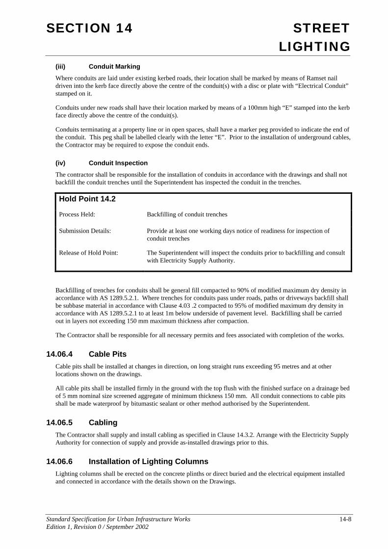
(iv) Conduit Inspection
The contractor shall be responsible for the installation of conduits in accordance with the drawings and shall not backfill the conduit trenches until the Superintendent has inspected the conduit in the trenches.
Hold Point 14.2
Process Held: Backfilling of conduit trenches
Submission Details: Provide at least one working days notice of readiness for inspection of conduit trenches
Release of Hold Point: The Superintendent will inspect the conduits prior to backfilling and consult with Electricity Supply Authority.
Backfilling of trenches for conduits shall be general fill compacted to 90% of modified maximum dry density in accordance with AS 1289.5.2.1. Where trenches for conduits pass under roads, paths or driveways backfill shall be subbase material in accordance with Clause 4.03 .2 compacted to 95% of modified maximum dry density in accordance with AS 1289.5.2.1 to at least 1m below underside of pavement level. Backfilling shall be carried out in layers not exceeding 150 mm maximum thickness after compaction.
The Contractor shall be responsible for all necessary permits and fees associated with completion of the works.
14.06.4 Cable Pits Cable pits shall be installed at changes in direction, on long straight runs exceeding 95 metres and at other locations shown on the drawings.
All cable pits shall be installed firmly in the ground with the top flush with the finished surface on a drainage bed of 5 mm nominal size screened aggregate of minimum thickness 150 mm. All conduit connections to cable pits shall be made waterproof by bitumastic sealant or other method authorised by the Superintendent.
14.06.5 Cabling The Contractor shall supply and install cabling as specified in Clause 14.3.2. Arrange with the Electricity Supply Authority for connection of supply and provide as-installed drawings prior to this.
14.06.6 Installation of Lighting Columns Lighting columns shall be erected on the concrete plinths or direct buried and the electrical equipment installed and connected in accordance with the details shown on the Drawings.
SECTION 14 STREET LIGHTING
Standard Specification for Urban Infrastructure Works 14-9 Edition 1, Revision 0 / September 2002
The outreach and column shall be pulled together tightly as recommended by the pole manufacturer using a winch (eg Tirfor) to prevent rotation of the outreach under wind loads.
The lighting columns shall be mounted for true vertical alignment (+/- 0.5 degree) on the concrete plinths by means of the levelling nuts under the mounting base and then secured tightly in place by means of the nuts on top of the mounting base.
The Contractor shall supply and install the 20 mm diameter plastic drainage tube under the mounting base.
The gap under the mounting base shall be completely filled with cement mortar and exposed edges neatly chamfered.
The plug and flex assembly shall be clamped to the bottom of the control gear tray and installed so that there is no slack present in the lead. The use of cable ties is not an acceptable clamp.
The luminaire shall be connected to the lamp control gear unit by 2.5 sq mm twin and earth TPS cable through the column. The luminaire shall be end mounted onto the lighting spigot on the column, securely locked in position and weather proofed at the point of entry of the spigot.
The alignment of the luminaire shall be parallel to the grade of the road and the outreach arm shall be at right angles to the traffic lane.
The specified lamp shall be fitted into the luminaire.
The luminaire column and equipment shall be fully earthed as specified in clause 3.3.
14.06.7 Commissioning and Testing On completion of each section of street lighting the Contractor shall test and commission the street lighting circuits and associated control equipment.
All work shall be subject to inspection by the Electricity Supply Authority to determine its acceptability. Evidence of a satisfactory inspection by the Electricity Supply Authority is to be provided to the Superintendent on completion of the commissioning and testing. A satisfactory inspection by the Electricity Supply Authority is not to be considered as compliance with the Contract. All work shall be subject to inspection by the Superintendent to assess its compliance with the Contract.
Each defect noted by BEPCON, the Electricity Supply Authority or the Superintendent during the inspections and tests shall constitute a non conformance under the Contract.
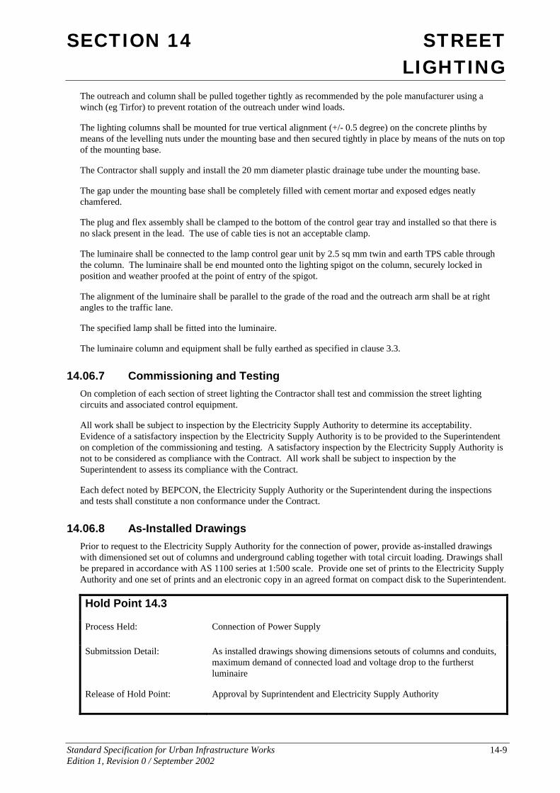
14.06.8 As-Installed Drawings Prior to request to the Electricity Supply Authority for the connection of power, provide as-installed drawings with dimensioned set out of columns and underground cabling together with total circuit loading. Drawings shall be prepared in accordance with AS 1100 series at 1:500 scale. Provide one set of prints to the Electricity Supply Authority and one set of prints and an electronic copy in an agreed format on compact disk to the Superintendent.
Hold Point 14.3
Process Held: Connection of Power Supply
Submitssion Detail: As installed drawings showing dimensions setouts of columns and conduits, maximum demand of connected load and voltage drop to the furtherst luminaire
Release of Hold Point: Approval by Suprintendent and Electricity Supply Authority

SECTION 14 STREET LIGHTING
Standard Specification for Urban Infrastructure Works 14-10 Edition 1, Revision 0 / September 2002
14.07 MEASUREMENT AND PAYMENT
Payment shall be made for all activities associated with completing the work detailed in this Specification in accordance with Pay Item 1404P1-3 and 1406P1-7 inclusive.
If any pay item for which a quantity of work is listed in the Contract has not been priced by the Contractor, it shall be understood that due allowance has been made in the prices of other pay items for the cost of the activity which has not been priced.
The Contractor shall allow in the pay items generally for the costs associated with all testing required to prove conformance of the works as specified.
Pay Item 1404P1 Lighting Columns The unit of measurement shall be per lighting column installed of each height as listed in the sub items.
This pay item shall be inclusive of all work and materials required for the installation of the columns of each height, including the column, cable terminations, electrical components and erection.
A separate pay item shall be included in the Contract for each lighting column height.
1404P1.1 Less than 6m Column height 1404P1.2 6.5m Column height 1404P1.3 9.0m Column height 1404P1.4 10.5m Column height 1404P1.5 12.0m Column height 1404P1.6 13.5m Column height 1404P1.7 15.0m Column height 1404P1.8 Greater than 15.0m Column height
Pay Item 1404P2 Lightings and Light Fittings – Watts The unit of measurement shall be per lighting and/or light fitting installed.
This pay item shall be inclusive of all work and materials required for the installation including the lighting or fitting, lamps, lamp control gear units, electrical components, cabling and erection.
Pay Item 1404P3 Relocated Lighting Columns The unit of measurement shall be per lighting column of each height relocated.
This pay item shall be inclusive of all work and materials required for the removal and re-installation of the columns including the removal, cabling and re-erection.
A separate pay item shall be included in the Contract for relocated column height.
R1404P3.1 Less than 6 m Column height R1404P3.2 6.5m Column height R1404P3.3 9.0m Column height R1404P3.4 10.5m Column height R1404P3.5 12.0m Column height R1404P3.6 13.5m Column height R1404P3.7 15.0m Column height R1404P3.8 Greater than 15.0m Column height
SECTION 14 STREET LIGHTING
Standard Specification for Urban Infrastructure Works 14-11 Edition 1, Revision 0 / September 2002
Pay Item 1406P1 Streetlighting Fees and Co-Ordination Costs This shall be a Lump Sum item.
This pay item shall include fees and charges payable to the Electricity Supply Authority and BEPCON, co-ordination costs, costs associated with the delivery of as-installed drawings and other costs not included in other items.
Pay Item 1406P2 Supply and Lay Conduit The unit of measurement shall be per lineal metre of conduit installed.
This pay item shall be inclusive of the supply of the conduits and required bends, trenching, laying of conduit in trench or structure, backfilling and the provision of draw wire.
Pay Item 1406P3 Supply and Lay Cable The unit of measurement shall be per lineal metre of cable installed.
This pay item shall be inclusive of the supply of the cable and installation of the cable in the conduits.
Pay Item 1406P4 Cable Pits The unit of measurement shall be per pit installed.
This pay item shall be inclusive of the supply of cable pits, Australian Power Products P4 Vipit or approved equivalent, excavation and installation.
Pay Item 1406P5 Concrete Plinth for Lighting Column The unit of measurement shall be per plinth installed.
This pay item shall be inclusive of all work and materials required for the construction of the plinth including excavation, concrete, anchor bolts assembly, conduits and cable jointing pit Type P2 Vipit.
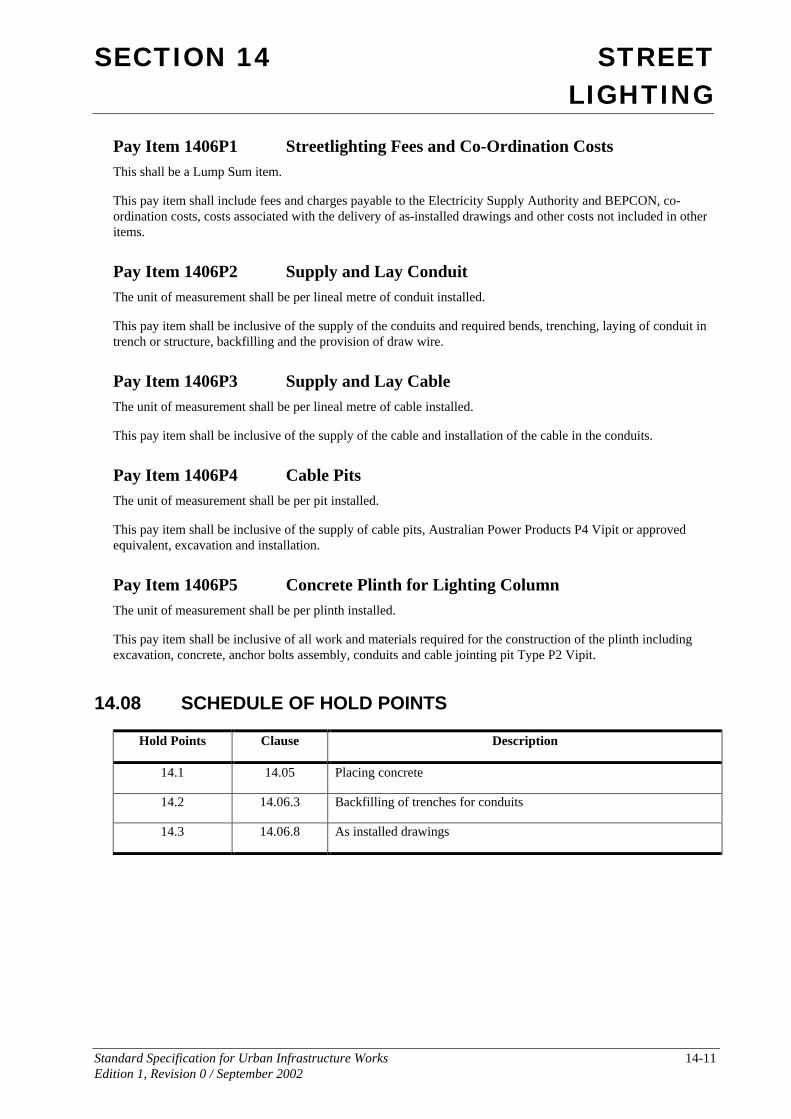
14.08 SCHEDULE OF HOLD POINTS
Hold Points Clause Description
14.1 14.05 Placing concrete
14.2 14.06.3 Backfilling of trenches for conduits
14.3 14.06.8 As installed drawings