section 10 american ball joint pipe · pdf file · 2013-04-25american ball joint...
TRANSCRIPT

Section 10
AMERICANBall Joint Pipe

AMERICAN Ball Joint Pipefor Water and Other Liquids
AMERICAN Ball Joint Piping complies with requirements of ANSI/AWWA C151/A21.51 and ANSI/AWWA C153, which are applicable to its manufacture. These and other standards are referenced throughout this Section either by the full ANSI/AWWA designation or by only the AWWA numbering, such as AWWA C151.
AMERICAN Flex-Lok® Pipe incorporates a very flexible ball-and-socket type joint for use in such installations as subaqueous pipe-line construction. The provision for significant changes in alignment, with available joint deflections of 25º for sizes 4”-12” and 15º for sizes 14”-60” in any direction, and the rugged features of AMERICAN Flex-Lok Pipe
make it especially adaptable to the most diffi-cult installations. This rugged joint configura-tion has an excellent record of performance, and under some of the toughest installa-tion conditions, it has provided long life and trouble-free service. Economy and depend-ability have been proven in many installations under widely varying conditions.
Typical Applications forAMERICAN Ball Joint Pipe
10-1
River CrossingsWhere deep water and strong currentsare encountered, as in unstable chan-nels and under flood stage conditions. Where deep trenches, steep banks and other difficult approaches require special construction considerations.
Busy WaterwaysWhere installation time and maneuver-ability are critical factors.
Tidal WatersWhere changing currents and water depths are encountered, and where the line is subject to movement.
River IntakesWhere it is necessary to have a flexible intake, the level of which may be adjust-ed with changing water levels.
Swamps and FloodlandsWhere water and earth are subject to seasonal variations, or where the under-ground line must give with the sub-
surface movements caused by tempera-ture change, moisture content or other factors.
HillsidesWhere steep grades are encountered, where trenching and backfillingare impossible, or where the line mayhave unstable bedding.
Seismic EnvironmentsWhere significant ground movements due to earthquakes are anticipated, par-ticularly suited for piping outside struc-tures where differential settlement can occur.
Difficult and InaccessibleLocationsWhere trenching is impossible, working conditions are hazardous, service cannot be interrupted, or lines are inaccessible for maintenance or repair. All scenarios requiring a combination of significant joint deflection and positive joint re-straint.

AMERICAN Flex-Lok Boltless Ball Joint Pipe — manufactured in 4”-60”* sizes — is a rugged, boltless, flexible joint pipe designed and manufactured to assure the greatest economy in installation with maximum performance and reliability. This ductile iron pipe meets all applicable requirements of AWWA C151 and is designed to withstand severe installation and service conditions encountered in river crossings, treated wastewater outfall lines, water supply intakes, swamps, floodlands and rugged terrain where significant joint deflection may be required. AMERICAN Flex-Lok Boltless Ball Joint Pipe provides variable deflection up to at least 15°, and the joint may be deflected to metal binding position at maximum deflection without harm to the pipe or joint components. This is a result of the unique design and functionality of the pipe and joint components. In sizes 4”-12” the configuration incorporates the additional flexible restraint provided by AMERICAN’s Flex-Ring joint, which cumulatively results in greater joint deflection capabilities, up to 25°.
Spherical Socket The spherical socket of the AMERICAN Flex-Lok Joint is cast of ductile iron and is accurately machined to accommodate the ball of the adjoining pipe. The thick wall and bell section provides superior strength to minimize the stresses resulting from installation and service conditions. The Flex-Lok Joint gasket recess inthe socket is designed and manufactured to provide easy insertion and positive seating of the gasket to avoid displacement during assembly and for constant compression of the gasket through the entire range of deflection of the assembled joint. Spherical Ball The ball end of the AMERICAN Flex-Lok Joint is accurately machined to fit into the adjoining pipe socket and to provide constant compression of the gasket through the entire range of deflection of the assembled joint. The inside surface of the ball is shaped so that the waterway will not be significantly obstructed at any angle of joint deflection.
10-2
30”-60” Flex-Lok Joint System
4”-12” Flex-Lok Joint System 14”-24” Flex-Lok Joint System
*Check AMERICAN for 64” requirements. **The spherical ball and socket ends of 54” and 60” Flex–Lok pipes are fastened to the barrels of the pipe with a Fastite gasket and locking ring arrangement instead of threads.
AMERICAN Ductile IronFlex-Lok® Ball Joint Pipe

Flex-Lok Gasket The AMERICAN Flex-Lok Joint uses the basic dual hardness gasket design of the AMERICAN Fastite Joint that has been proven with millions of joints over approximately 55 years. Designed to provide maximum sealability, the Flex-Lok gasket is manufactured to AMERICAN’s rigid specification to assure controlled dimensional and material properties. The snug fit of the gasket in the socket cavity, the design of the socket buttress and the hard section of the gasket act to restrain the gasket from dislodging during assembly.
LOCKING SYSTEM Two types of locking systems are used to prevent longitudinal joint separation of the AMERICAN Flex-Lok joint, depending on pipe size. In the 4”-24” sizes, the locking system employs a substantial external locking ductile iron gland and sizes 4”-12” also use the proven positive joint restraint system of the Flex-Ring joint. Both the spherical socket component and spherical ball component of the Flex-Lok joint in this size range have a Flex-Ring joint that is pre-assembled at AMERICAN. For 30”- 60” sizes, the joint is restrained with a ductile iron retainer ring fitted into a mating groove inside the heavy-section bell.
4”-24” Flex-Lok Pipe Joint The locking gland of the 4”-24” AMERICAN Flex-Lok joint is cast of ductile iron. The gland has internal lugs that interlock with external lugs on the bell.
The lugs on the gland are passed between and beyond the lugs on the bell periphery and the gland is then rotated to lock the joint and prevent separation.
10-3
Cross-sectional view showing theAMERICAN Flex-Lok Joints in thedeflected position. Note that thewaterway remains unobstructedwhen the joint is fully deflected.
30”-60”Flex-Lok Joint
4”-24”Flex-Lok Joint
An exploded view showing the component parts of the 4”-24” AMERICAN Flex-LokBoltless Ball Joint: 1–Ductile Iron Socket. 2–Rubber gasket. 3–Ductile Iron Ball.4–Locking gland. 5–Locking wedge.
10-4
5 4 3 2 1
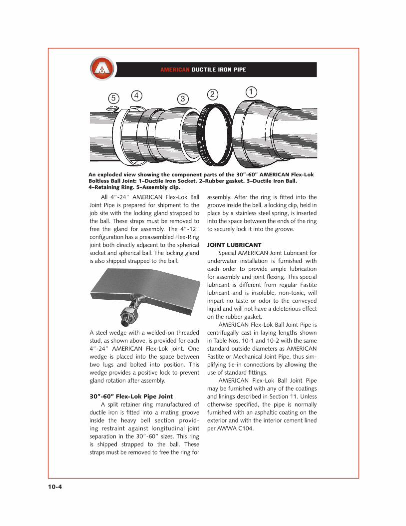
An exploded view showing the component parts of the 30”-60” AMERICAN Flex-LokBoltless Ball Joint: 1–Ductile Iron Socket. 2–Rubber gasket. 3–Ductile Iron Ball.4–Retaining Ring. 5–Assembly clip.
All 4”-24” AMERICAN Flex-Lok Ball Joint Pipe is prepared for shipment to the job site with the locking gland strapped to the ball. These straps must be removed to free the gland for assembly. The 4”-12” configuration has a preassembled Flex-Ring joint both directly adjacent to the spherical socket and spherical ball. The locking gland is also shipped strapped to the ball.
A steel wedge with a welded-on threaded stud, as shown above, is provided for each 4”-24” AMERICAN Flex-Lok joint. One wedge is placed into the space between two lugs and bolted into position. This wedge provides a positive lock to prevent gland rotation after assembly.
30”-60” Flex-Lok Pipe Joint A split retainer ring manufactured of ductile iron is fitted into a mating groove inside the heavy bell section provid-ing restraint against longitudinal joint separation in the 30”-60” sizes. This ring is shipped strapped to the ball. These straps must be removed to free the ring for
assembly. After the ring is fitted into the groove inside the bell, a locking clip, held in place by a stainless steel spring, is inserted into the space between the ends of the ring to securely lock it into the groove.
JOINT LUBRICANT Special AMERICAN Joint Lubricant for underwater installation is furnished with each order to provide ample lubrication for assembly and joint flexing. This special lubricant is different from regular Fastite lubricant and is insoluble, non-toxic, will impart no taste or odor to the conveyed liquid and will not have a deleterious effect on the rubber gasket. AMERICAN Flex-Lok Ball Joint Pipe is centrifugally cast in laying lengths shown in Table Nos. 10-1 and 10-2 with the same standard outside diameters as AMERICAN Fastite or Mechanical Joint Pipe, thus sim-plifying tie-in connections by allowing the use of standard fittings. AMERICAN Flex-Lok Ball Joint Pipe may be furnished with any of the coatings and linings described in Section 11. Unless otherwise specified, the pipe is normally furnished with an asphaltic coating on the exterior and with the interior cement lined per AWWA C104.

10-5
Table No. 10-1A
Sizein.
LayingLength*
ft./in.
WorkingPressure**
psi
TWall
Thickness***in.
Per PipeLength
Per LengthIncl. JointMaterials
Per FootIncl. JointMaterials
Full of Airlb.
Full of Waterlb.
Nominal Weight in Pounds Nominal Underwater Weight PerLength Incl. Joint Materials†
14 21’–6” 250 0.41 450 480 22.3 311 427 16 21’–7” 250 0.43 680 720 33.4 370 638 18 21’–8” 250 0.45 945 1000 46.2 396 8861 10 21’–7–5/8” 250 0.47 1265 1325 61.2 418 1178 12 21’–8–5/8” 250 0.49 1565 1665 76.7 377 1481
See notes at end of Table No. 10–1B.
Table No. 10-1B
Sizein.
LayingLength*
ft./in.
WorkingPressure**
psi
TWall
Thickness***in.
Per PipeLength
Per LengthIncl. JointMaterials
Per FootIncl. JointMaterials
Full of Airlb.
Full of Waterlb.
Weight in Pounds Underwater Weight PerLength Incl. Joint Materials†
14 20’–6” 250 0.51 1760 1880 191.7 193 1615 16 20’–6” 250 0.52 2045 2200 107.3 15 1880 18 20’–6” 250 0.53†† 2425 2610 127.3 –129†† 2245 20 20’–6” 250 0.54†† 2810 3040 148.3 –327†† 2610 24 20’–6” 250 0.56†† 3605 3910 190.7 –889†† 3360
*The laying length in the above tables are subject to trim pipe allowance in accordance with AWWA C151.Also, this is the fully homed or inserted laying length of 4”–24” Flex–Lok pipe. In installations where 4”–24” joints are pulled or extended to metal–binding contact of joint locking members, some slight additional laying length will be gained as a function of the removal of joint assembly space. Contact AMERICAN when lengths are critical, or when it is necessary to locate ball joints at specific stations, etc. The joints will seal properly in any axial position from fully homed to fully extended and with any joint deflection angles up to the maximum rating. **The working pressure is AMERICAN’s suggested standard water working pressure. Contact AMERICAN if higher working pressure is involved. ***Thicknesses correspond to Special Class 56. Check AMERICAN if pipe with other wall thickness is required. †Does not include lining weight. Underwater pipe weights are for fresh water. Sea water is approximately 3% heavier than fresh water, and these weights should be adjusted accordingly for sea water installation.††When full of air, pipe of this thickness will float unless weight is added. See Table No. 11–1 for cement liningweights. Gross weight, including pipe, gland and lining, is painted on each length of Flex–Lok pipe to aid in field calculations of actual buoyancy.
AMERICAN Ductile Iron Flex-Lok Boltless Ball Joint PipeFor Water, Sewage and Other Liquids
4”-12”Standard Classes and Thicknesses
The following table shows suggested water pressure ratings with thickness designations and weights in accordance with applicable requirements of ANSI/AWWA C150/A21.50 and ANSI/AWWA C151/A21.51. It is intended that the ultimate determination of suitable thicknesses should be made by the design engineer with consideration of both installation methods and ultimate service conditions of the line.
AMERICAN Ductile Iron Flex-Lok Boltless Ball Joint PipeFor Water, Sewage and Other Liquids
14”-24”Standard Classes and Thicknesses
The following table shows suggested water pressure ratings with thickness designations and weights in accordance with applicable requirements of ANSI/AWWA C150/A21.50 and ANSI/AWWA C151/A21.51. It is intended that the ultimate determination of suitable thicknesses should be made by the design engineer with consideration of both installation methods and ultimate service conditions of the line.

10-6
AMERICAN Ductile Iron Flex-Lok Boltless Ball Joint PipeFor Water, Sewage and Other Liquids
30”-60”Standard Classes and Thicknesses
Table No. 10-2
Sizein.*
LayingLengthft./in.**
WorkingPressure
psi***
TWall
Thicknessin.
Per PipeLength
Per LengthIncl. JointMaterials
Per FootIncl. JointMaterials
Full of Airlb.
Full of Waterlb.
Weight in Pounds Underwater Weight Per Length Incl. Joint Materials
30 21’–7” 250 0.63 5735 5759 266.8 –2017 4944 36 22’–1” 250 0.73 8455 8499 384.9 –2914 7296 42 22’–6” 250 0.83 12225 12287 546.1 –3506 10548 48 22’–6” 250 0.93 16050 16138 717.2 –4486 13855 54 23’–0” 250 1.05 24000 24150 1050 –3125 20950 60 23’–3” 250 0.87 26650 26875 1156.0 –5920 23410
Flex–Lok joint pipe, in sizes 30”–60”, may be supplied with either threaded–on or mechanically restrained connec�tions for attaching the ball and socket to the pipe barrel. *Contact AMERICAN on requirements for 64” and larger Flex–Lok. **Laying length is subject to trim pipe allowance in accordance with AWWA C151. Also, this is based on the fully extended or pulled–to–metal–locking position of 30”–60” Flex–Lok joints. In installations where 30”–60” joints are not pull-extended in the assembly procedure, the tabulated laying lengths will be reduced by approximately 2” per joint in 30”–48” sizes and 2–1/2” in 54” and 60” sizes, which is the result of the non–removal of the joint assembly clearance space in the joints. Contact AMERICAN when lengths are critical, or when it is necessary to locate ball joints at specific stations, etc. The joints will seal properly in any axial position from fully homed to fully extended and with any joint deflection angles up to maximum rating when the joint is extended. ***The working pressure is AMERICAN’s suggested standard water working pressure. Contact AMERICAN if higher working pressure is involved. †Thicknesses correspond to Special Class 56 for 30”–54” sizes and Pressure Class 350 for the 60” size. ContactAMERICAN if pipe with other wall thickness is required. ††Does not include lining weight. Underwater pipe weights are for fresh water. Sea water is approximately 3% heavier than fresh water, and these weights should be adjusted accordingly for sea water installation. †††When full of air, pipe of this thickness will float unless weight is added. See Table No. 11–1 for cement liningweights. Gross weight, including pipe, ring and lining, is painted on each length of Flex–Lok pipe to aid in field calculations of actual buoyancy.
The following table shows suggested water pressure ratings with thickness designations and weights in accordance with applicable requirements of ANSI/AWWA C150/A21.50 and ANSI/AWWA C151/A21.51. It is intended that the ultimate determination of suitable thicknesses should be made by the design engineer with consideration of both installation meth–ods and ultimate service conditions of the line.
†† † †
† †

10-7
AMERICAN Ductile IronFlex-Lok Boltless Ball Joint Pipe
4”-12”Technical Data
Table No. 10-3A
Sizein.
Ain.
Nin. Gland Gasket Locking
WedgeComplete
Set
LubricantPoundsPer Joint
MaximumJoint
Deflection
MaximumSafe
End Pullin Tons†
Joint MaterialsWeight in Pounds
14 14.80 11.79 27 1 1 29 .09 25° 21 16 16.90 13.91 37 1 1 39 .12 25° 35 18 19.05 16.38 50 1 2 53 .16 25° 49 10 11.10 18.84 67 1 3 71 .27 25° 63 12 13.20 21.56 89 1 3 93 .40 25° 76
*Refer to Table No. 10–1A for thickness “T” dimensions. †Contact AMERICAN for greater end pull requirements.
AMERICAN Ductile IronFlex-Lok Boltless Ball Joint Pipe
14”-24”Technical Data
Table No. 10-3B
Sizein.
Ain.
Nin. Gland Gasket Locking
WedgeComplete
Set
LubricantPoundsPer Joint
MaximumJoint
Deflection
MaximumSafe
End Pullin Tons†
Joint MaterialsWeight in Pounds
14 15.30 24.43 115 2 3 120 .50 15° 90 16 17.40 26.78 147 3 4 154 .60 15° 100 18 19.50 29.70 181 3 4 188 .75 15° 110 20 21.60 32.59 221 4 4 229 .90 15° 119 24 25.80 37.29 297 5 4 306 1.10 15° 130
*Refer to Table No. 10–1B for thickness “T” dimensions. †Contact AMERICAN for greater end pull requirements.
*
*

10-8
AMERICAN Ductile IronFlex-Lok Boltless Ball Joint Pipe
30”-60”Technical Data
Table No. 10-4
Sizein.
Ain.
Nin. Locking
Ring Gasket LockingClip
CompleteSet
LubricantPoundsPer Joint
MaximumJoint
Deflection**
MaximumSafe End
Pull inTons†
Joint Materials Weight/lb.
30 32.00 40.57 17 6 1 24 1.60 15° 225 36 38.30 48.43 35 8 1 44 2.20 15° 255 42 44.50 56.71 53 8 1 62 2.70 15° 305 48 50.80 63.67 77 10 1 88 3.50 15° 350 54 57.56 73.37 121 22 2 145 4.70 15° 450 60 61.61 80.13 198 27 3 228 10 15° 500
Flex–Lok joint pipe, in sizes 30”–60”, may be supplied with either threaded–on or mechanically restrained connections for attaching the ball and socket.*Refer to Table No. 10–2 for thickness “T” dimensions.**The full 15° rated deflection and laying length of 30”–60” joints is most readily obtained by fully extending the joints.†Contact AMERICAN for greater end pull requirements.Contact AMERICAN on requirements for 64” or larger Flex–Lok.
54” AMERICAN Flex-Lok® Joint pipe being assembled for an outfall installation.
*

10-9
AMERICAN Ductile IronFlex-Lok Boltless Ball Joint Pipe
4”-12”Laying Length
Table No. 10-5A
Sizein.
L.L.Maximum
LayingLength*ft.-in.
O.L.Maximum
OverallLength**
ft.-in.
Ball Weightlb.
Ain.
Bin.
Bell Weightlb.
14 21’–6” 21’–091/4” 1.38 1.77 55 41 16 21’–7” 21’–101/4” 1.38 2.01 72 61 18 21’–8” 21’–113/4” 1.42 2.34 99 88 10 21’–7–5/8” 21’–111/2” 1.42 2.61 143 123 12 21’–8–5/8” 22’–1” 1.42 2.91 184 169
*The maximum laying length (and accordingly the maximum overall length) is subject to trim pipe allowance in acordance with AWWA C151. Also, this is the fully homed or inserted laying length of 4”–24” Flex–Lok pipe. In installations where 4”–24” joints are pulled or extended to metal–binding contact of joint locking members, some slight additional laying length will be gained as a function of the removal of joint assembly space. The joints will seal properly in any axial position from fully homed to fully extended and with any joint deflection angles up to the maximum rating. **Overall Length (O.L.) equals Laying Length L.L. + A + B. Flex–Lok Ball ends may be integrally cast or threaded on, our option. *** Refer to Table No. 10–1B for thickness “T” dimension.
Table No. 10-5B
Sizein.
L.L.Maximum
LayingLength*ft.-in.
O.L.Maximum
OverallLength**
ft.-in.
Ball Weightlb.
Ain.
Bin.
Bell Weightlb.
14 20’–6” 20’–113/4” 1.73 3.32 177 183 16 20’–6” 20’–111/4” 1.73 3.58 193 225 18 20’–6” 20’–115/8” 1.73 3.87 277 297 20 20’–6” 21’–003/8” 2.01 4.16 347 375 24 20’–6” 21’–003/4” 2.01 4.68 491 552
AMERICAN Ductile IronFlex-Lok Boltless Ball Joint Pipe
14”-24”Laying Length
A B
A B
*Refer to Table No. 10–1A for thickness “T” dimension.
A B
A B
***
*
10-10
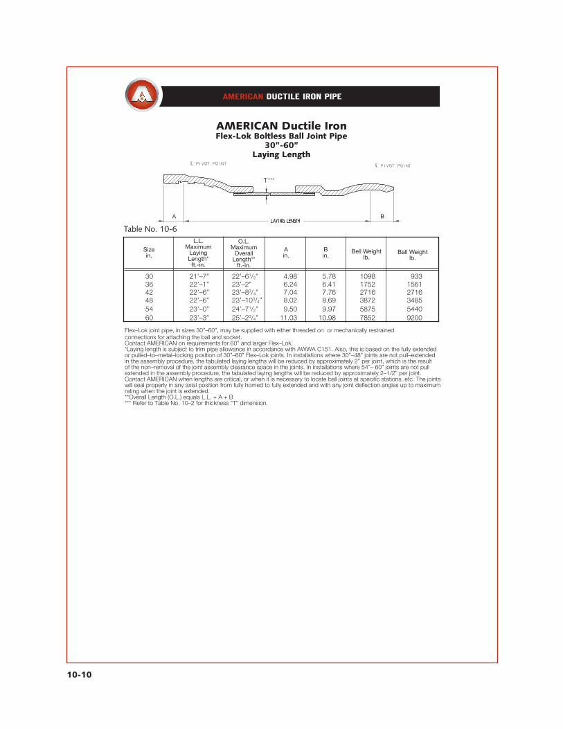
Table No. 10-6
Sizein.
L.L.Maximum
LayingLength*ft.-in.
O.L.Maximum
OverallLength**
ft.-in.
Ball Weightlb.
Ain.
Bin.
Bell Weightlb.
30 21’–7” 22’–61/2” 14.98 15.78 1098 933 36 22’–1” 23’–2” 16.24 16.41 1752 1561 42 22’–6” 23’–83/4” 17.04 17.76 2716 2716 48 22’–6” 23’–103/4” 18.02 18.69 3872 3485 54 23’–0” 24’–71/2” 19.50 19.97 5875 5440 60 23’–3” 25’–23/4” 11.03 10.98 7852 9200
AMERICAN Ductile IronFlex-Lok Boltless Ball Joint Pipe
30”-60”Laying Length
Flex–Lok joint pipe, in sizes 30”–60”, may be supplied with either threaded on or mechanically restrained connections for attaching the ball and socket.Contact AMERICAN on requirements for 60” and larger Flex–Lok.*Laying length is subject to trim pipe allowance in accordance with AWWA C151. Also, this is based on the fully extended or pulled–to–metal–locking position of 30”–60” Flex–Lok joints. In installations where 30”–48” joints are not pull–extended in the assembly procedure, the tabulated laying lengths will be reduced by approximately 2” per joint, which is the result of the non–removal of the joint assembly clearance space in the joints. In installations where 54”– 60” joints are not pull extended in the assembly procedure, the tabulated laying lengths will be reduced by approximately 2–1/2” per joint. Contact AMERICAN when lengths are critical, or when it is necessary to locate ball joints at specific stations, etc. The joints will seal properly in any axial position from fully homed to fully extended and with any joint deflection angles up to maximum rating when the joint is extended.**Overall Length (O.L.) equals L.L. + A + B*** Refer to Table No. 10–2 for thickness “T” dimension.
A BA B
***

10-11
Flex-Lok Boltless Ball JointCombinations with Other JointsLaying Length — Overall Length
Flex-Lok Socket and Flange Pipe ......................................19’-9” L.L. + AFlex-Lok Socket and Plain End Pipe ..................................19’-9” L.L. + AFlex-Lok Ball and Flange Pipe ...........................................19’-6” L.L. + BFlex-Lok Ball and Plain End Pipe .......................................20’-0” L.L. + B
MaximumOverall Length
ft.-in.
Maximum Laying Length
ft.-in.***Type Joints
***These lengths are generally applicable for 14”–24” Flex–Lok pipes. In other pipe sizes, AMERICAN may have capabilities to produce longer lengths. See Table 10–7 for similar 30”–60” configuration lengths, and contact AMERICAN for specific longer lengths if desired. Use formulas to obtain overall length corresponding to maximum laying length or to any other required laying length. Other joint combinations are available with Flex–Lok pipe, including Flex–Lok Ball and Ball in certain sizes. Contact AMERICAN for further details on any desired combination.
Flex-Lok Ball JointCombinations with Other JointsLaying Length — Overall Length
Table No. 10-7
Sizein.
Flex-Lok Socketand Flangeor Plain End
Pipe
Flex-Lok Balland Flangeor Plain End
Pipe
Flex-Lok Socketand Flangeor Plain End
Pipe
Flex-Lok Balland Flangeor Plain End
Pipe
30 20’–61/4” 20’–71/2” 20’–111/4” 21’–11/2” 36 20’–73/4” 20’–111/2” 21’–2” 21’–6” 42 20’–10” 21’–2” 21’–5” 21’–93/4” 48 20’–103/4” 21’–2” 21’–63/4” 21’–101/2” 54 21’–11/2” 21’–41/2” 21’–11” 22’–21/2” 60 21’–23/4” 21’–61/4” 22’–13/4” 22’–51/4”
Use formulas to obtain overall length corresponding to other required laying lengths. Overall length of Flex–Lok Socket and Flange/P.E. Pipe = L.L. + A Overall length of Flex–Lok Ball and Flange/P.E. Pipe = L.L. + B Other joint combinations are available with Flex–Lok pipe, including Flex–Lok Ball and Ball in certain sizes. Contact AMERICAN for further details on any desired combination.
Maximum Laying Length(ft.-in.)
Maximum Overall Length(ft.-in.)

10-12
12 2’–7” 2’–10” 590 505
AMERICAN Ductile IronFlex-Lok Boltless Ball Joint Pipe
4”-24” Flex-Lok Connecting Pieces
Table No. 10-8
Table No. 10-9
Sizein.
Sizein.
Flex-Lok BallAssembly Closure
Flex-Lok SocketAssembly Closure
Flex-Lok BallAssembly Closure
Flex-Lok SocketAssembly Closure
Flex-Lok BallAssembly Closure
Flex-Lok SocketAssembly Closure
Flex-Lok BallAssembly Closure
Flex-Lok SocketAssembly Closure
14 2’–10” 2’–10” 135 120
30 3’–7” 3’–5” 12480 12633 36 4’–0” 3’–8” 13976 14147 42 4’–8” 4’–4” 16481 16479 48 4’–9” 4’–6” 18614 19026 54 7’–0” **9’–0” 13378 13834
16 2’–9” 2’–10” 205 185 18 2’–8” 2’–10” 305 270 10 2’–7” 2’–10” 415 370
14 3’–1” 3’–0” 720 590 16 3’–2” 3’–0” 910 760 18 3’–3” 3’–1” 1130 935 20 3’–4” 3’–2” 1385 1135 24 3’–5” 3’–3” 1910 1530
*Laying lengths shown exclude the bolted on pulling flange.Pulling flange contains 2 taps (1” taps for 4”–10” and 2” taps for 12”–54”).Flex–Lok Closure Assemblies are available on loan basis for use in installing lines by pulling and for testing of lines after installation.They are normally furnished in pairs, i.e., one Ball and Closed End Assembly and one Socket and Closed End Assembly.Assembled weights include the bolted on pulling flange
*Laying Lengths shown exclude the bolted on pulling flange.**Contact AMERICAN for the availability of a shorter closure piece if desired.Pulling flange contains 2 taps (2” taps for 12”–54”).Flex–Lok Closure Assemblies are available on loan basis for use in installing lines by pulling and for testing of lines after installation.They are normally furnished in pairs, i.e., one Ball and Closed End Assembly and one Socket and Closed End Assembly.Assembled weights include the bolted–on pulling flange.†60” Flex–Lok Closure Assemblies are constructed differently than 30”–54”, but with the same functionality (a pulling plug with taps isinserted in the bell or bell end, instead of a short length of flange pipe as pictured). Contact AMERICAN.
30”-54”† Flex-Lok Closure Assemblies
Laying Lengths*
Laying Lengths*
Assembled Weight in Pounds
Assembled Weight in Pounds

10-13
Field assembly of 4”-24” AMERICAN Flex-Lok Boltless Ball Joint Pipe is fast and simple. The following procedure is recommended: 1. Remove the steel straps holding the gland on the ball. Thoroughly clean ball and gasket recess in the socket. The intermediate Flex-Ring joint comes from AMERICAN pre-assembled, complete. Note that no solvents should be used in cleaning the ball and gasket recess. 2. Insert the special Flex-Lok gasket into the gasket recess with small section of gasket facing outward. 3. For underwater installation, coat entire ball and the exposed surface of the gasket completely with the AMERICAN Underwater Joint Lubricant, which is furnished with the pipe. This coating will provide ample lubrication for assembly and joint flexing, and this special lubricant is insoluble in water. 4. Position the pipe in near straight alignment to facilitate assembly. Position the leading edge of the ball into the socket and
push or pull pipe together using methods similar to those shown on page 2-11. 5. Position the locking gland and rotate to interlock with matching lugs on the pipe bell. 6. Insert the steel locking wedge into the space between two lugs with threaded stud through one of the drilled holes in the gland (two holes are provided 180° apart, but only one locking wedge is required per joint). Secure wedge by tightening nut on threaded stud. This wedge securely locks the gland in place. 7. Disassembly of the joint may be accomplished by essentially following the assembly instructions in reverse order.
If required, an additional quantity of lubricant can be supplied or a lubricant can be prepared in the field by mixing one gallon of melted paraffin and one-half gallon of linseed oil. Do not use other lubricants as they may be injurious to the gasket or impart taste or odor to the conveyed water.
AMERICAN Ductile IronFlex-Lok Boltless Ball Joint Pipe
4”-24”Assembly Instructions
1 2
4 5
3
6

10-14
AMERICAN Ductile IronFlex-Lok Boltless Ball Joint Pipe (Internal Retaining Ring Type)
30”-60”Assembly Instructions
Field assembly of 30”-60” AMERICANFlex-Lok Boltless Ball Joint Pipe is fast and simple. The following procedure is recommended: 1. Remove the steel strap, U-bolt and eye-bolt holding the retaining ring and let it hang freely on the shank of the ball. Thoroughly clean the outside of the ball and the socket recesses inside the bell. Do not remove protective coating from ball or bell. Note that no solvents should be used in cleaning the ball and gasket recess. 2. Insert the special Flex-Lok gasket intothe gasket recess with small section of gasketfacing outward. 3. For underwater installation, coat entire ball and the exposed surface of the gasket completely with the AMERICAN Underwater Joint Lubricant, which is furnished with the pipe. This coating will provide ample lubrication for assembly and joint flexing, and this special lubricant is insoluble in water. 4. Position the pipes in near straight alignment to facilitate assembly. Position the leading edge of the ball into the socket. Pull pipe together using a device such as a roller chain pull lift, which can be furnished by AMERICAN if desired. 5. Orient the loose retaining ring so the gap is at the top. Insert retaining ring into recess inside bell. Check to ensure ring is in the socket recess all the way around the joint.
6. Insert the assembly clip in the space between the ring ends and push or caulk intoposition. Note that the spring end of the clip must be oriented inward toward the ball as shown on page 10-4 and in Photo 6 above.
7. Disassembly can be easily accomplished with a reversal of these instructions. Any pulled or extended joints must, of course, be first pulled or pushed back together to allow removal of the assembly clip and the retaining ring. Also, a small tapped hole is provided in the face of the loose retaining ring approximately 180° from the assembly clip (normally at the bottom). A bolt can be threaded into this hole if disassembly is needed. This is often helpful in lifting the retaining ring out of engagement in the socket.
If required, an additional quantity of lubricantcan be supplied or, in some cases, a lubricant can be prepared in the field by mixing one gallon of melted paraffin and one-half gallon of linseed oil. Do not use other lubricants as they may be injurious to the gasket or impart taste or odor to the conveyed water. Approximately 2” of relative separatingmovement or “joint take-up” will occur in each joint if the joint is extended or “pulled” (before locking members metal-bind to prevent further movement).
1 2 3 4
5 6

10-15
Installation From Bank (Line Pulling) In many instances it is possible to plan installation methods for waterway crossings so that work will be confined to firm ground with offshore operations minimized or eliminated.AMERICAN Flex-Lok Joint Pipe may be assembled on an inclined ramp, or on launching ways, and pulled to the opposite shore by cable. The entire line may be moved as a unit or in sections. The line may be floated or pulled directly into an excavated trench depending on existing conditions. AMERICAN Flex-Lok Joint Pipe is positively locked against separation and the allowable end pull permits the assembled pipeto be pulled as a line into otherwise inaccessibleareas such as rivers, swamps and quicksand.
The joints are designed so that the joint sealing is not affected by the tension of pulling, and after the line is in final position, no further joint work is necessary. Many installations have been made by this method, and on several occasions two or more parallel lines have been pulled simultaneously. In the construction of a ramp, the most readily available materials can be used, such as timbers, rails or steel beams. Pipe may be assembled so that the heavy flanges are in contact with the ramp or the pipe may be cradled on cross supports equipped with guide cleats. The design of the ramp and the materials used dictate how the pipe should besupported. The deflection of individual joints provides line flexibility, enabling movement
AMERICAN Ball Joint Pipe InstallationsMethods of Installation
Time and time again, AMERICAN Ball Joint Pipelines have been installed where the con-ditions of the job site have challenged the ingenuity of the design engineer and installation contractor. The design features of Flex-Lok Pipe make it readily adaptable to extremely difficult situations. It has been installed by a variety of methods — both unique and conventional — with an unexcelled record of success. Many installations have been made using marine equipment, thus minimizing or eliminating all underwater work. Unnavigable and navigable waters have been crossed with all jointing and installation work being performed on the opposite banks, with appropriate design and construction planning. The majority of installations involve one or more of the installation procedures describedas follows:
Bank installation in progress, where most of the work is performed on firm groundand the pipe is pulled across waterway by cable. (Note rail weights strapped on to create slight negative buoyancy of this size line pulled beneath barge traffic).

10-16
through moderate bends into various elevations and locations. The grade and longradius bend of the ramp are planned for gradual line deflection and maximum controlof line movement. In line pulling, analysis of bottom conditions should be made by thorough soundings to determine possible obstructions and resistance to be encountered by the pipe, as well as support for the pipeline in contact with the bottom. Closure pieces with cable eyes and test taps can be furnished with the pipe on a rental basis. An advantage is sometimes obtained byfastening an improvised deflector or sled in front of the lead socket flange.
Line Flotation AMERICAN Flex-Lok Joint Pipe can be installed by various methods including the use of line flotation. Some sizes of unfilled pipe are lighter than the water they displace and will float. See Table Nos. 10-1 and 10-2. If the unfilled pipe is heavier than the water it displaces, then pontoons must be secured to the line to provide the buoyancy if flotation is desired. Unless bottom conditions or other circumstances dictate that the line be floated into position, it is usually better to pull the line submerged along the bottom with slight negative buoyancy. When necessary,
pontoons may be used to lighten the weight of a long line pulled along the bottom. Unless water depth is relatively shallow, approximately 10 feet or less, a line floated into position should be supported as it is lowered to the bottom. This precaution is necessary to avoid placing excessive deflection and beam stresses on the joints. Used commercial steel drums are generally available and often can be economically used as pontoons during installation. In designing flotation gear, consideration should be given to the depth at which the drums used will collapse due to external pressure.
Flotation provided by attached spheres facilitated installation of this 30” pipeline with Flex-Lok Joints.
Flex-Lok Joint Pipe can be pulled into position with a bulldozer, winch or crane with “dead man.”

10-17
Installation From a Barge Designed especially for submarine installations, AMERICAN Flex-Lok Joint Pipe is adaptable for installation from practically any barge or other type of marine equipment that can be used for laying pipe from the water’s surface. The ruggedness and flexibility of the Flex-Lok Joint permits the suspension of the end of the pipeline above water for the addition of pipe while the balance of the line is suspended on a launching ramp or rests on the bottom. Normally a ramp is employed in conjunction with the barge for the best control
of movement, prevention of undesirable bending loads on joints and for ease of operation. The ramp is designed to reach from the barge to the bottom and to rise and fall with the changing bottom elevations. As pipe is added onto the suspended end of the line, the barge is moved forward, pulling the ramp from under the suspended section allowing it to progressively descend to the bottom. Care should be taken to prevent any barge movement that could cause damaging overdeflection and bending moments to occur in the pipe joints.
48” Flex-Lok Pipe beingpositioned for assembly.The ramp attachedto the barge is used asthe assembly platform,and as the joints aremade, the barge ismoved forward, allowingassembled piping toslide into the water.

10-18
InstallationThe outstanding construction advantages afforded by AMERICAN Flex-Lok Pipe should be fully considered and used for long, trouble-free service. For example, where river bottoms are of unstable soils, the flexibility of Flex-Lok Pipe will allow substantial line movement or settlement, and remain leak-free. Movement of the installed line, however, should be minimized as far as practical and confined to the underwater section of the line. It is suggested that the river bottom be trenched or dragged to stable soils where practical. Also, the ends of the lines extending above the water should be stabilized for connection to other lines. It is generally suggested that the ends of the crossings be installed in firm earth, above the high-water mark, to provide firm anchorage. Where the connecting ends of the crossings cannot be located in firm soils, other suitable means of anchoring should be provided. After a river crossing is installed, it is normally suggested that the line be backfilledand allowed to settle for a reasonable period before end connections are made. This is due to uncertain bedding conditions that may be present in many installations. Submerged lines should be filled with water to aid their settlement. The significant deflection provided by AMERICAN Ball Joints practically eliminates the need for line fittings; however, where steep approaches or horizontal bends are encountered requiring greater than normal line deflection, the use of short AMERICAN
Ball Joint connecting pieces will provide additional deflection within a short distance.
Testing Upon completion of a river crossing, the ends of the line may be closed for testing by the use of closure pieces, which are available on loan from AMERICAN.
Connections When connecting Ball Joint river crossing lines to land lines, the river crossing pipe should normally be installed first. Sleeves are often used for connecting Ball Joint pipe to other pipelines. Such connections facilitate the joining of a field-cut piece, allow moderate movement of the river crossing ends, reduce stresses and provide for easy line maintenance. Long pattern mechanical joint sleeves are recommended for making connection to mechanical joint or Fastite joint ductile iron pipe, both of which have the same outside diameters as Ball Joint pipe. Connections to pipe of other diameters require special connecting pieces designed to fit specific installation requirements. The use of AMERICAN Flex-Lok Joint Pipe with or without special restrained expansion sleeves may be advantageous in seismic environments.
AMERICAN will assist in any river crossing project by making a detailed layout and by giving suggestions for installation procedures to accomplish the crossing.
AMERICAN Ball Joint PipeRecommendations
AMERICAN reserves the right to modify or change designs, materials, specifications, or dimensions shown herein without prior notice.
This is a preprint of a section from the 19th Edition of the AMERICAN Pipe Manual. References may be made in this section to other sections of this manual.
APM10—REV—03-13
AMERICAN DUCTILE IRON PIPE
®