section 00 91 11 addendum number 1 particulars … · section 00 91 11 addendum number 1...
TRANSCRIPT

921�12/922�12 Cosmo and Dental � JALC 00 91 11 � 1 ADDENDUM NUMBER 1
SECTION 00 91 11
ADDENDUM NUMBER 1
PARTICULARS
1.01 DATE: June 10, 2013
1.02 PROJECT: JALC Cosmetology and Dental Assisting Renovations
1.03 PROJECT NUMBER: 921(12/922(12
1.04 OWNER: John A. Logan – Board of Trustees
1.05 ARCHITECT: Architechniques, Ltd. (Steve Sims, AIA)
TO: PROSPECTIVE BIDDERS
2.01 This Addendum forms a part of the Contract Documents and modifies the Bidding Documents dated May 31, 2013, with amendments and additions noted below.
2.02 Acknowledge receipt of this Addendum in the space provided in the Bid Form. Failure to do so may disqualify the Bidder.
2.03 This Addendum consists of 70 pages.
CHANGES TO THE PROJECT MANUAL
3.01 Section 03 33 01 – Cast(In(Place Concrete:
A. Insert attached Specification Section into project manual.
3.02 Section 09 65 10 – Resilient Sheet Flooring, Clarification:
A. Clarification: The luxury vinyl flooring noted in the drawings as Alternates 3A and 2B are found in
this section.
3.03 Section 09 68 13 – Carpet Tile, Clarification:
A. Revision: 2.01, A, 1: Shaw “Peto II 20” EW 24” #59371, color to be chosen by the Architect.
3.04 Section 10 22 20 – Demountable Partitions, ADD the following;
A. DIRTT Contact: Jane Mosey�Nicoletta, Resource One. Phone: 217�753�5742. Fax: 217�753�
5748. Email: [email protected].
3.05 Section 10 51 13 – Heavy Duty Steel Lockers, ADD the following;
A. Standard Steel Lockers (For use in Dental Locker Rooms).
1. Style: Double Tier Locker, Cat #5222.
2. Locker Size: 12 inches wide, 18 inches deep, 36 inches high
3.06 Section 11 21 53 – Cosmetology and Hair Styling Equipment;
A. Delete Section 2.1 in its entirety. Replace with below:
“2.1. Eurpoean Style, Backwash Shampoo Bowls and Cabinets
A. Manufacturer/Model: Kaemark EL�70. www.kaemark.com
1. See Plumbing Schedule and manufacturers website for sink faucet, hot and cold braided hoses, drain hose, receiver plate, hand held sprayer, hose and head, stopper, hair trap and drain assembly.”

921�12/922�12 Cosmo and Dental � JALC 00 91 11 � 2 ADDENDUM NUMBER 1
3.07 Section 22 11 00 – Facility Water Distribution:
A. Add to subsection 2.1; A that Type L piping is also permitted.
3.08 Section 22 60 13 – Medical and Gas Vacuum Systems:
A. Insert attached Specification Section into project manual.
3.09 Section 23 05 29 – Hangers and Supports for HVAC Piping and Equipment:
A. Insert attached Specification Section into project manual.
3.10 Section 23 05 53 – Identification for HVAC piping and Equipment:
A. Insert attached Specification Section into project manual.
3.11 Section 23 07 00 – HVAC Insulation:
A. Insert attached Specification Section into project manual.
3.12 Section 23 34 00 – HVAC Fans:
A. Insert attached Specification Section into project manual.
3.13 Section 31 20 00 (( Earthmoving:
A. Insert attached Specification Section into project manual.
3.14 Section 31 22 19 – Finish Grading:
A. Insert attached Specification Section into project manual.
3.15 Section 31 25 00 – Erosion and Sedimentation Control:
A. Insert attached Specification Section into project manual.
3.16 Section 33 40 00 – Storm Drainage Utilities:
A. Insert attached Specification Section into project manual.
CHANGES TO THE DRAWINGS – DENTAL ASSISTING AREA
4.01 Drawing D(1, Demolition Plan
1. Revision: Delete Key Note #6. The existing lab tables will be removed by JALC prior to the start of work.
4.02 Drawing A(1, Dental Assisting Floor Plan
1. Revision: All walls in Radiology D166b shall be “E” type walls. Refer to sheet A�3 for detail.
2. Add: Room “Corridor D173”. This corridor consists of the area from the existing stair (Southeast side of building) to the double fire doors in the main corridor.
4.03 Drawing A(3, Partition Types
1. Clarification: Gyp board on wall types “C”, “D”, and “E” shall extend 6” above ceiling.
2. Revision: Wall type “D”, detail 4 this sheet, delete “lead�lined” note. Shall use regular 5/8” gyp board on this wall type.
3. Clarification: Lead thickness on lead�lined gyp board is 1/16”.
4.04 Drawing A(5, Room Finish Schedule
1. Add: Corridor D173. Replace existing carpet in this area. Match existing corridor carpet.

921�12/922�12 Cosmo and Dental � JALC 00 91 11 � 3 ADDENDUM NUMBER 1
4.05 Drawing PD(1, Plumbing Demo Plan (Sheet Re(Issued)
1. Remove existing sheet in its entirety and replace with attached sheet PD�1.
4.06 Drawing P(1, Plumbing Plan (Sheet Re(Issued)
1. Add the following to both SK�1 sinks in Dental Assisting Lab D166: “Provide infrared faucet Delta Model 1505T with 8” cover plate, battery operated.” Provide this faucet in lieu of scheduled faucet for this sink.
2. Add the following to the SK�1 sink in Lab D172: “Provide infrared faucet Delta Model 1505T with 8” cover plate, battery operated.” Provide this faucet in lieu of scheduled faucet for this sink.
3. Clarification: All sinks are provided and installed by plumber except the four sidewall sinks in Lab D172. Those are to be provided as part of the dental equipment, installed by plumber.
4.07 Drawing P(2, Plumbing Notes, Schedules and Details
1. Modify the following with the Plumbing Fixture, LAV�1: Change from pop�up drain to open grid strainer.
4.08 Drawing E(1, Electrical Plan
1. Revise Keyed Note No. 5 to add a 1” PVC conduit beneath the floor slab for owner provided data wiring.
CHANGES TO THE DRAWINGS – COSMETOLOGY AREA
5.01 Drawing C(1, Site Plan (New Sheet)
1. Add new sheet, attached to this Addendum. This sheet shows new site work, including a new sidewalk and associated details.
5.02 Drawing D(1, Demolition Plan
1. Add Note: Coordinate additional wall demolition for new fixtures in Toilet D271A and Toilet D271B with both Mechanical and Plumbing drawings.
2. Clarification: Temporary walls (Keynote 35) do not have to extend to deck.
5.03 Drawing A(1, Floor Plan
1. Clarification: Wall type “E”, noted between rooms D238 and D238a, is a 9’�0” tall wall. Refer to sheet A�3 for wall type detail.
2. Clarification: New wall between Classroom D214 and Laundry D213a/Dispensary D215 shall be 1 hour rated (wall type “D”). Refer to sheet A�3 for wall type detail.
3. Clarification: Existing walls in Classroom D238 and Hairstyling Lab D238a need 2 ½” metal stud furring and gyp board over existing walls to allow for electrical service. This occurs at existing walls in these two rooms where hairstyling stations will be installed. See detail 6 on sheet A�7 (attached to this Addendum).
5.04 Drawing A(3, Wall Sections
1. Clarification: Wall type “D”, detail 4 on this sheet, shall be 1 hour rated construction UL #U407. All penetrations through this wall type shall be sealed.
2. Clarification: Wall type “A”, detail 1 on this sheet, gyp board to extend 6” above ceiling as noted.
5.05 Drawing A(5.1, Door and Window Schedule and Details
1. Revision: Door 212, Elevation mark “A”, from D214 to D214a, delete “1/4” FIRELITE”, delete “20 MINUTE” rating. Door is non�rated.

921�12/922�12 Cosmo and Dental � JALC 00 91 11 � 4 ADDENDUM NUMBER 1
5.06 Drawing A(7, Addendum 1 – Plans and Details (New Sheet)
1. Add new sheet, attached to this Addendum. This drawing shows the construction of a new ramp in Corridor D213.
5.07 Drawing MD(1.0, Existing Floor Plan – HVAC (Sheet Re(Issued)
1. Remove existing sheet in its entirety and replace with attached sheet MD�1.0.
5.08 Drawing M(1.0, New Floor Plan – HVAC (Sheet Re(Issued)
1. Add the following: NEW exhaust fan to Nail Technology Classroom D230. Provide centrifugal rooftop mounted upblast fan located in between the two supply diffusers near the exterior wall approximately in the southeast portion of the classroom. Design base is: Greenheck Model CUE�101�C NEMA 3R Disconnect Switch Speed controller Hinged Curb cap Roof Curb GPI�19�12�G20 Gravity Damper WD�100�PB�12x12 490 cfm at 0.2” ESP 814 RPM 0.03 Operating HP with a 1/8 HP motor 115/60/1 power Sones not to exceed 1.1
Route 12”x12” duct from exhaust fan down to new Return Grille R�3 located in ceiling.
5.09 Drawing PD(1.0, Existing Floor Plan – Sanitary (Sheet Re(Issued)
1. Remove existing sheet in its entirety and replace with attached sheet PD�1.0.
5.10 Drawing P(1.0, New Floor Plan ( Sanitary (Sheet Re(Issued)
1. Remove existing sheet in its entirety and replace with attached sheet P�1.0.
5.11 Drawing P(1.1, New Floor Plan ( Domestic (Sheet Re(Issued)
1. Remove existing sheet in its entirety and replace with attached sheet P�1.1.
5.12 Drawing P(1.2 – Plumbing Notes, Schedules and Details
1. Modify the following SK�4 within the Plumbing Fixture Schedule: Tag: SK�4 Description: Salon Hair Sink Integral to Chair Manufacturer/Model: Kaemark EL�70 Faucet/Flush Valve/Trim: Include all Accessories Listed in 11 21 53 Remarks: Contractor to provide and install; see spec section 11 21 53.
2. Modify the following with the Plumbing Fixture, LAV�1: Change from pop�up drain to open grid strainer.
5.13 Drawing ED(1, Electrical Demolition Plan
1. Add the following General Note: “Two existing speakers in the Lobby Corridor shall be removed and relocated to the new Corridor D213. Speakers shall be equally centered in new corridor. Existing wiring shall be extended to the new speaker locations as required for a complete functional system.”
2. Add the following General Note: “The existing lobby ceiling shall be raised as indicated on Sheet D�1, Keyed Note No. 30. Existing wiring above this ceiling shall be raised to above new ceiling height. Intercept existing wiring above ceiling and splice/extend wiring to above new ceiling as required. The contractor shall be responsible for field verification of all existing wiring that needs

921�12/922�12 Cosmo and Dental � JALC 00 91 11 � 5 ADDENDUM NUMBER 1
to be raised. All existing conduits/cable trays shall be removed or raised to above new ceiling to maintain integrity of all existing circuits.”
5.14 Drawing E(1, Electrical Plan
1. Revise Keyed Note No. 3 to state: “Relocated Panel LL as indicated on Sheet ED�1. Existing feeder circuit shall be extended to new panel location.”
2. Add a fire alarm manual pull station to the new exterior door in Cosmetology Lab D234. Connect wiring to existing initiation wiring circuit in this area.
3. Add an exit sign to the new exterior door in Cosmetology Lab D234. Connect to the unswitched leg of the lighting circuit in this area.
4. Add a 120V electrical connection to the new exhaust fan in Nail technology D230. Circuit shall be routed to Panel LL, Circuit No. 29. Provide a single pole toggle switch at door into room to manually switch fan.
5. Add a coaxial cable to the new entry vestibule on the north side of the building for an owner�supplied CCTV camera. Coaxial cable shall be routed above the ceilings and through the chases provided to the existing Campus Public Safety office. Contractor shall field verify location of existing Public Safety Office and route.
5.15 Drawing E(3, Electrical Details
1. Add Light Fixture T Type G to be manufactured by Gardco, Model 106L355LANWUNIV.
END OF ADDENDUM NUMBER 1

033301�1
DIVISION 03 � CONCRETE Section 033301 – Site Cast�In�Place Concrete
PART 1 � GENERAL
1.1 WORK INCLUDED
A. This section covers site cast�in�place concrete, including reinforcing steel, forms, finishing, curing, and other appurtenant work.
B. PPC Concrete sidewalk, 5” thick.
1.2 RELATED WORK
A. Site cast�in�place concrete shall be accurately formed and properly placed and finished as indicated on the drawings and specified herein. The Contractor shall inform the Engineer at least 24 hours in advance of the times and places at which he intends to place concrete.
B. Data and Drawings: All submittals of data and drawings shall be in accordance
with the submittals section unless otherwise noted herein. C. Existing metal railing at top of existing retaining wall removed under this project
shall be reused as the metal railing at the top of the new concrete retaining wall. Method of installation shall be the same as the method used on the existing wall.
1.3 MATERIALS
A. Cement: ASTM C150, Type I, II, or III. B. Fly Ash: ASTM C618, Class F, except loss on ignition shall not exceed 4 percent. C. Fine Aggregate: Clean natural sand, ASTM C33. Artificial or manufactured sand
will not be acceptable. D. Coarse Aggregate: Crushed rock, washed gravel, or other inert granular material
conforming to ASTM C33, except that clay and shale particles shall not exceed one percent.
E. Water: Clean and free from deleterious substances. F. Admixtures:
1. Retarder: ASTM C494, Type D, nonair�entraining solution of metallic salts of hydroxylated carboxylic acids; Grace “Daratar�HC”, Master Builders “MB�HC”, Protex “Protard”, or Sika Chemical “Plastiment”.
2. Pasticizer: ASTM C494, Type A, nonaire�entraining solution of metallic salts of hydroxylated carboxylic acids; Grace “WRDA�HC” or Master Builders “MBHC�N”.
3. Air�Entraining Agent: ASTM C260; Grace “Daravair”, Master Builders “MB�VR”, Protex “AES”, or Sika Chemical :AER”.

033301�2
G. Reinforcing Steel:
1. Bars, Except Weldable: ASTM A615, Grade 60, deformed. 2. Bars, Weldable: ASTM A706 or A615, Grade 60, deformed, with
maximum carbon equivalent of 0.55. 3. Beam Stirrups and Column Ties: ASTM A615, Grade 40, deformed. 4. Column Spirals: ASTM A82, cold drawn wire. 5. Welded Wire Fabric: ASTM A185 or A497. 6. Bar Supports: CRSI Class 1, plastic protected, or Class 2, stainless steel
protected. 7. Mechanical Connections: Erico Products “Cadweld T�Series” or
“Lenton”, or Richmond “Dowel Bar Splice System”. H. Forms:
1. Prefabricated: Simplex “Industrial Steel Frame Forms”, Symons “Steel Ply”, or Universal “Uni�form”.
2. Plywood: Product Standard PS1, waterproof, resin�bonded, exterior type Douglas fir; face adjacent to concrete Grade B or better.
3. Fiberboard: Fed Spec LLL�B�810, Type II tempered, waterproof, screenback, concrete form hardboard.
4. Lumber: Straight, uniform width and thickness, and free from knots, offsets, holes, dents, and other surface defects.
5. Chamfer Strips: Clear white pine, surface against concrete planed. 6. Form Coating: Nox�Crete “Form Coating”, L&M “Debond”, Protex “Pro�
Cote, or Richmond “Rich Cote”; nonstaining and nontoxic after 30 days.
I. Wedge Inserts: Malleable iron, with galvanized askew�head bolts, nuts, and washers; Hohmann and Barnard “HW”, Richmond “Peerless”, or Weston “WC50”.
J. Polyethylene Film: Product Standard PS17; 6 mil. K. Membrane Curing Compound and Floor Sealer: Fed Spec TT�C�800, type I,
Class 1; min 18 percent solids; nonyellowing; unit moisture loss 0.039 gm/cm2 max; Gifford�Hill “Sealco 800”, ProSoCo “Kure and Seal”, Protex “Acrychlor”, or Sonneborn “Kure�N�Seal”.
1.4 PRELIMINARY REVIEW
A. As stipulated in the quality control section, all tests and reports required for preliminary review shall be made by an independent testing laboratory at the expense of the contractor. Reports covering the source and quality of concrete materials and the concrete proportions proposed for the work shall be submitted to the Engineer for review before concrete work is started. Review of these reports will be for general acceptability only and continued compliance with all contract provisions will be required.
B. Aggregates. Reports on aggregates shall include the following information:
1. Fine Aggregate:
a. Source and type. b. Gradation. c. Deleterious substances.

033301�3
2. Course Aggregate:
a. Source and type. b. Gradation and abrasion loss. c. Deleterious substances. d. Results of sodium or magnesium sulfate soundness test.
C. Mix Design: Using concrete materials acceptable to the Engineer, a tentative concrete mix shall be designed and tested for each size and gradation of aggregates and for each consistency intended for use on the work. Design quantities and test results of each mix shall be submitted for review. Mixes shall be adjusted in the field as necessary to meet the requirements of these specifications.
The report for each tentative concrete mix submitted shall contain the following
information:
1. Slump on which design is based. 2. Total gallons of water per cubic yard. 3. Brand, type, composition, and quantity of cement. 4. Brand, type, composition, and quantity of fly ash. 5. Specific gravity and gradation of each aggregate. 6. Ratio of fine to total aggregates. 7. Weight (surface dry) of each aggregate per cubic yard. 8. Brand, type, ASTM designation, active chemical ingredients, and quantity
of each admixture. 9. Air content. 10. Compressive strength based on 7 day and 28 day compression tests. 11. Time of initial set.
D. Testing: Aggregate shall be sampled and tested in accordance with ASTM C33. In addition, the bulk specific gravity of each aggregate shall be determined in accordance with ASTM C127 and ASTM C128.
Two sets of compression test cylinders, three cylinders per set, shall be made
from each proposed concrete mix. One set of three cylinders shall be tested at an age of 7 days and the other set shall be tested at an age of 28 days. Concrete test specimens shall be made, cured, and stored in conformity with ASTM C192 and tested in conformity with ASTM C39.
Slump shall be determined in accordance with ASTM C143 and total air content
shall be determined in conformity with ASTM C231. Initial set tests shall be made at ambient temperatures of 70 F and 90 F to
determine compliance with the initial set time specified herein. The test at 70 F shall be made using concrete containing the specified plasticizing and air�entraining admixtures. The test at 90 F shall be made using concrete containing the specified retarding and air�entraining admixtures. Initial set shall be determined in accordance with ASTM C403.
Contractor shall be responsible for all costs resulting from required testing.
1.5 LIMITING REQUIREMENTS
A. Unless otherwise specified, each concrete mix shall be designed and concrete shall be controlled within the following limits.

033301�4
B. Cement Content: The quantity of Portland cement, expressed in pounds per
cubic yard, shall be as indicated in the following table. These minimum cement quantities shall apply only to concrete containing a specified water�reducing admixture. If, for any reason, the water�reducing admixture is omitted, the cement shall be increased 10 percent. At the option of the Contractor, fly ash may be substituted for up to 15 percent of the Portland cement quantity shown on the basis of 1.5 pounds of fly ash for each pound reduction in cement.
Coarse Aggregate Size From No. 4 Sieve to____ Concrete Slump ½” ¾” 1” 2 inches 573 545 517 3 inches 592 564 536 4 inches 611 583 555 5 inches 630 602 573 6 inches 649 620 592 C. Total Water Content: Total water content of concrete shall not exceed 5.7
gallons of water per hundred pounds of cement in the mix, or equivalent cement weight if fly ash is added.
D. Slump: Concrete slump shall be kept as low as possible consistent with proper
handling and thorough compaction. Unless otherwise authorized by the Engineer, slump shall not exceed 4 inches.
E. Ratio of Fine to Total Aggregates: The ratio of fine to total aggregates based on
solid volumes (not weights) shall be: Concrete Aggregate Size Minimum Maximum Ratio Ratio 1/2 inch 0.40 0.55 3/4 inch 0.35 0.50 1 inch 0.30 0.46 F. Initial Set: the initial set as determined by ASTM C403 shall be attained 5 ½
hours plus or minus one hour after the water and cement are added to the aggregates. The quantity of retarding admixture shall be adjusted to compensate for variations in temperature and job conditions.
G. Total Air Content: The total volumetric air content of concrete after placement
shall be 6 percent plus or minus one percent. Air may be omitted from interior slabs which are to be trowel finished.
H. Admixtures: The admixture content, batching method, and time of introduction to
the mix shall be in accordance with the manufacturer’s recommendations for minimum shrinkage and for compliance with these specifications. A water�reducing admixture shall be included in all concrete.
No calcium chloride or admixture containing chloride from other than impurities
from admixture ingredients will be acceptable. I. Strength: the minimum acceptable compressive strengths as determined by
ASTM C39 shall be:

033301�5
Age Minimum Strength 7 days 2500 psi 28 days 4,000 psi
1.6 STORAGE OF MATERIALS
A. Cement and fly ash shall be stored in suitable moisture proof enclosures. Cement and fly ash which have become caked or lumpy shall not be used.
Aggregates shall be stored so that segregation and the inclusion of foreign
materials is prevented. The bottom 6 inches of aggregate piles in contact with the ground shall not be used.
Reinforcing steel shall be carefully handled and shall be stored on supports which
will keep the steel from contact with the ground.
1.7 FORMS
A. Forms shall be designed to produce hardened concrete having this shape, lines, and dimensions indicated on the drawings. Forms shall conform to ACI 347 and the following additional requirements:
1. Forms for surfaces which will be exposed to view when construction is
completed shall be prefabricated plywood panel forms, job�built plywood forms, or forms that are lined with plywood or fiberboard. Forms for exposed surfaces shall be paid out in a regular and uniform pattern with the long dimension of panels vertical and all joints aligned. The forms shall produce finished surfaces that are free from offsets, ridges, waves, and concave or convex areas, within the tolerances specified herein.
2. Plywood or lined forms will not be required for surfaces which are
normally submerged or not ordinarily exposed to view. Other types of forms, such as steel or unlined wooden forms, may be used for surfaces which are not restricted to plywood or lined forms and may be used as backing for form linings. Concrete forms are required above all extended footings.
3. Flat segmental forms not more than 24 inches wide may be used for
forming curved surfaces 25 feet in diameter or larger.
B. Design: Forms shall be substantial and sufficiently tight to prevent leakage or mortar. Forms shall be braced or tied to maintain the desired position, shape, and alignment during and after concrete placement. Walers, studs, internal ties, and other form supports shall be sized and spaced so that proper working stresses are not exceeded.
Beams and slabs supported by concrete columns shall be formed so the column
forms may be removed without disturbing the supports for the beams or slabs. Wherever the top of a wall will be exposed to weathering, the forms on at least
one side shall not extend above the top of the wall and shall be brought to true line and grade. At other locations, forms shall be brought to a true line and grade, or a wooden guide strip shall be provided at the proper location on the forms so that the top surface can be finished with a screed or template for concrete which

033301�6
is to be finished to a specified elevation, slope, or contour. At horizontal construction joints in walls, the forms on one side shall not extend more than 2 feet above the joint.
Temporary openings shall be provided at the bottom of column and wall forms
and at other points where necessary to facilitate cleaning and inspection. C. Form Ties: Form ties shall be of the removable end, permanently embedded
body type and shall have sufficient strength and rigidity to support and maintain the form in proper position and alignment without the use of auxiliary spreaders. Cones shall be provided on the outer ends of each tie and the permanently embedded portion shall be at least one inch back from the concrete face. Form ties for water�bearing walls shall be provided with waterseal washers located on the permanently embedded portion of the ties at the approximate center of the wall. Permanently embedded portions of form ties which are not provided with threaded ends shall be constructed so that the removable ends are readily broken off without damage to the concrete. The type of form ties used shall be acceptable to the Engineer.
Form ties in exposed surfaces shall be uniformly spaced and aligned in horizontal
and vertical rows. D. Edges and Corners: Chamfer strips shall be placed in forms to bevel all salient
edges and corners, except the top edges of walls and slabs which are to be tooled and edges which are to be buried. Equipment bases shall have formed beveled salient edges for all vertical and horizontal corners unless specifically indicated otherwise on the drawings. Unless otherwise noted, bevels shall be ¾ inch wide.
E. Form Removal: Forms shall not be removed or disturbed until the concrete has
attained sufficient strength to safely support all dead and live loads. Shoring beneath beams or slabs shall be left in place and reinforced as necessary to carry any construction equipment or materials placed thereon. Care shall be taken in form removal to avoid surface gouging, corner or edge breakage, and other damage to the concrete.
1.8 REINFORCEMENTS
A. Reinforcements shall be accurately formed and shall be free from loose rust, scale, and contaminants which reduce bond. Unless otherwise indicated on the drawings or specified herein, the details of fabrication shall conform to ACI 315 and 318.
B. Shop Drawings and Bar Lists: Bar lists and drawings for the fabrication and
placing of reinforcements shall be submitted for review. C. Placement: Reinforcements shall be accurately positioned on supports, spacers,
hangers, or other reinforcements and shall be secured in place with wire ties or suitable clips.
Reinforcements shall not be installed for beams or slabs which are supported by
concrete columns until after the concrete for the column has been placed. D. Splices: Splices shall conform to the details indicated on the drawings and meet
ACI Standards. Splices at locations other than those indicated on the drawings shall be acceptable to the Engineer.

033301�7
Except where indicated on the drawings, welding or tack welding of reinforcement
is prohibited. Where welding is indicated on the drawings, weldable reinforcing steel having a carbon equivalent of not more than 0.55 shall be provided, and preheating and welding shall conform to AWS D104. Reinforcements upon which improper or unauthorized welding has been done shall be removed and replaced.
Whenever bars in tie beams subject to tensile loading must be spliced, a full
mechanical connection in compliance with ACI 318 shall be provided. A full mechanical connection shall develop in tension and compression at least 125 percent of specified yield strength of the spliced bars. Splices in adjacent bars shall be spaced at least 30 inches apart.
New retaining wall shall be dowelled into existing concrete wall with acceptable
lap lengths as outlined in ACI.
1.9 EMBEDMENTS
A. Anchor bolts, castings, steel shapes, conduit, sleeves, masonry anchorage, and other materials that are to be embedded in the concrete shall be accurately positioned in the forms and securely anchored. Conduits shall be installed between the reinforcing steel in walls or slabs which have reinforcement in both faces. In slabs which have only a single layer of reinforcing steel, conduits shall be placed under the reinforcement.
Unless installed in pipe sleeves, anchor bolts shall have sufficient threads to
permit a nut to be installed on the concrete side of the form or template. A second nut shall be installed on the other side of the form or template, and the two nuts shall be adjusted so that the bolt will be held rigidly in proper position.
Embedments shall be clean when installed. After concrete placement, surfaces
not in contact with concrete shall be cleaned of concrete spatter and other foreign substances.
1.10 BATCHING AND MIXING
A. Concrete shall be furnished by an acceptable ready�mixed concrete supplier and shall conform to ASTM C94.
B. Consistency: The consistency of concrete shall be suitable for the placement
conditions. Aggregates shall float uniformly throughout the mass and the concrete shall flow sluggishly when vibrated or spaded. The slump shall be kept uniform.
C. Delivery Tickets: A delivery ticket shall be prepared for each load of ready�mixed
concrete. A copy of each ticket shall be handed to the Engineer by the truck operator at the time of delivery. Tickets shall show the mix identification, quantity delivered, the amount of each material in the batch, the outdoor temperature in the shade, the time at which the cement was added, and the numerical sequence of the delivery.
1.11 PLACEMENT
A. The limits of each concrete pour shall be predetermined by the Contractor and shall be acceptable to the Engineer. All concrete within such limits shall be placed in one continuous operation.

033301�8
Before concrete is placed, forms, reinforcements, water stops, anchor bolts, and
embedments shall be rigidly secured in proper position; all dirt, mud, water, and debris shall be removed from the space to be occupied by concrete; all surfaces incrusted with dried concrete from previous placement operations shall be cleaned; and the entire installation shall be acceptable to the Engineer.
B. Bonding to Hardened Concrete: The surface of hardened concrete upon which
fresh concrete is to be placed shall be rough, clean, sound, and damp. The hardened surface shall be cleaned of all laitance, foreign substances (including curing compound), washed with clean water, and wetted thoroughly preceding placement of fresh concrete.
C. Conveying Concrete: Concrete shall be conveyed to the point of final deposit by
methods which will prevent separation or loss of ingredients. Concrete shall be placed in final position without being moved laterally in the forms more than 5 feet.
D. Placing Concrete: Concrete shall be placed in approximately horizontal layers of
proper depth for effective compaction; however, the depth of a layer shall not exceed 24 inches. Each layer of concrete shall be plastic when covered with the following layer, and the forms shall be filled at a rate of vertical rise of not less than 2 feet per hour. Vertical construction joints shall be provided as necessary to comply with these requirements.
Concrete shall be placed and compacted in wall or column forms before any
reinforcing steel is placed in the system to be supported by such walls or columns. The portion of any wall or column placed monolithically with a floor or roof slab shall not exceed 6 feet of vertical height. Concrete in walls or columns shall settle at least 2 hours before concrete is placed in the structural systems to be supported by such walls or columns.
Concrete shall be thoroughly settled when top finished. All laitance, debris, and
surplus water shall be removed from concrete surfaces at tops of forms by screeding, scraping, or other effective means. Wherever the top of a wall will be exposed to weathering, the forms shall be overfilled and after the concrete has settled, the excess shall be screeded off.
E. Compaction: During and immediately after placement, concrete shall be
thoroughly compacted and worked around all reinforcements and embedments and into the corners of the forms. Mechanical vibrators shall be used which will maintain at least 9,000 cycles per minute when immersed in the concrete. Each vibrator shall be driven by not smaller than a 1 ½ hp motor. Number and type of vibrators shall be acceptable to the Engineer.
F. Cold Weather Concreting: Except as modified herein, cold weather concreting
shall comply with ACI 306. The temperature of concrete at the time of mixing shall be not less than that shown in the following table for corresponding outdoor temperature (in shade) at the time of placement:
Outdoor Temperature Concrete Temperature Below 30 F 70 F Between 30 F and 45 F 60 F Above 45 F 45 F

033301�9
When placed, heated concrete shall not be warmer than 80 F. When freezing temperatures may be expected during the curing period, the
concrete shall be maintained at a temperature of at least 50 F for 5 days or 70 F for 3 days after placement. Concrete and adjacent form surfaces shall be kept continuously moist. Sudden cooling of concrete shall not be permitted.
G. Hot Weather Concreting: Except as modified herein, hot weather concreting shall
comply with ACI 305. At air temperatures of 90 F or above, concrete shall be kept as cool as possible during placement and curing. The temperature of the concrete when placed in the work shall not exceed 90 F.
Plastic shrinkage cracking, due to rapid evaporation of moisture, shall be
prevented. Concrete shall not be placed when the evaporation rate (actual or anticipated) equals or exceeds 0.2 pound per square foot per hour, as determined by Figure 2.1.5 in ACI 305.
1.12 TESTING
A. Field control tests, including aggregate gradation tests, slump tests, air content tests, and making compression test cylinders, shall be performed by the Engineer or testing laboratory personnel. The Contractor shall provide all facilities and the services of one or more employees as necessary to assist with the field control testing activities.
As stipulated in the quality control section, tests required during the progress of
the work shall be made at the expense of the Contractor. The frequency herein specified for each field control test is approximate. A
greater or lesser number of tests may be made, as required by the Engineer. B. Aggregate Gradation: Each 100 tons of fine aggregate and each 200 tons of
coarse aggregate shall be sampled and tested in accordance with ASTM D75 and C 136.
C. Fly Ash: Each 400 tons of fly ash shall be sampled and tested in accordance with
ASTM C618 and C311, respectively. The Contractor shall supply the Engineer with certified copies of supplier (source) test reports showing chemical composition and physical analysis, and certifying that the fly ash complies with the specifications for each shipment delivered to the concrete supplier. The certification shall be signed by both the Contractor and the concrete supplier.
D. Slump: A slump test shall be made for each 50 cubic yards of concrete. Slump
shall be determined in accordance with ASTM C143. E. Air Content: An air content test shall be made from one of the first three batches
mixed each day, and from each batch of concrete from which concrete compression test cylinders are made. Air content shall be determined in accordance with ASTM C231.
F. Compression Tests: Two sets of four concrete compression test cylinders shall
be made each day when from 25 to 100 cubic yards of concrete are placed. Two additional sets shall be made from each additional 100 cubic yards, or major fraction thereof, placed in any one day. Two cylinders of each set shall be tested at an age of 7 days and the other cylinders shall be tested at an age of 28 days. Compression tests will be evaluated in accordance with ACI 214 and 318.

033301�10
Test cylinders shall be made, cured, stored, and delivered to the laboratory in
accordance with ASTM C31 and tested in accordance with ASTM C39. Each set of compression test cylinders shall be marked or tagged with the date
and time of day the cylinders were made, the location in the work where the concrete represented by the cylinders was placed, the delivery truck or batch number, the air content, and the slump.
G. Test Reports: Test reports shall be prepared in three copies and shall be
distributed by the testing laboratory directly to the Resident project Representative and Contractor in accordance with the quality control section.
1.13 FINISHING UNFORMED SURFACES
A. Buried and permanently submerged concrete blocking and encasement will require no finishing except that necessary to obtain the required surface elevations or contours. The unformed surfaces of all other concrete shall be screeded and given an initial float finish followed by additional floating, and troweling where required.
B. Screeding: Screeding shall provide a concrete surface conforming to the proper
elevation and contour with all aggregates completely embedded in mortar. All screeded surfaces shall be free of surface irregularities with a height or depth in excess of ¼ inch as measured from a 10 foot straightedge.
C. Floating: Screeded surfaces shall be given an initial float finish as soon as the
concrete has stiffened sufficiently for proper working. Any piece of coarse aggregate which is disturbed by the float or which causes a surface irregularity shall be removed and replaced with mortar. Initial floating shall produce a surface of uniform texture and appearance with no unnecessary working of the surface.
Initial floating shall be followed by a second floating at the time of initial set. The
second floating shall produce a finish of uniform texture and color. Unless additional finishing is specifically required, the completed finish for unformed surfaces shall be the float finish produced by the second floating.
Floating shall be performed with hand floats or suitable mechanical compactor�
floats. D. Broom Finish: Surfaces of all exterior concrete stair treads and landings shall be
given a light broom finish providing a non slip surface. Brooming shall be done after the second floating and at right angles to the normal traffic direction.
E. Nonskip Finish: Tread surfaces of all interior concrete and concrete filled pan
type stairs shall be surfaced with aluminum oxide aggregate, “Alumdum” or “Emerundum”. Aggregate shall be uniformly graded from 100 percent retained on a No. 50 sieve to 100 percent passing a No. 8 sieve. Aggregate shall be uniformly distributed during steel troweling at the rate of ¼ pound per square foot, in accordance with the manufacturer’s recommendations, and as acceptable to the Engineer.
F. Troweling: Interior floor surfacing which will be exposed after construction is
completed, surfaces to be covered with resilient floor coverings or seamless floor covering, the exposed portion of the top of equipment bases, the top of interior
033301�11
curbs, and other surfaces designated on the drawings shall be steel trowel finished. Surfaces to be covered with elastomeric deck covering shall be lightly troweled but not burnished. Trowel finishing will not be required for floorswhich are normally submerged. Troweling shall be performed after the second floating when the surface has hardened sufficiently to prevent an excess of fines being drawn to the surface. Troweling shall produce a dense, smooth, uniform surface free from blemishes and trowel marks.
G. Finishing Surfaces for Bonding: All surfaces to be covered with concrete or
topping shall be float finished. All laitance, surface mortar, and unsound material shall be removed by brushing or air blasting at the time of initial set. Surfaces shall be rough, clean and sound. Floors and other flatwork surfaces to receive topping shall be given a broom finish.
H. Edging: Unless specified to be beveled, exposed edges of floated or troweled
surfaces shall be edged with a tool having ¼ inch corner radius. New retaining wall shall have exposed edges with 1” beveled edges.
1.14 CURING
A. Concrete shall be protected from loss of moisture for at least 7 days after placement; however, when concrete is being protected from low temperatures, the time period for curing by saturation shall be one day less than the duration of the low temperature protection.
Curing of concrete shall be by methods which will keep the concrete surfaces
adequately wet during the specified curing period. All concrete in the rapid mix/splitter structure, basin, filters, and clearwell shall be water cured; membrane or film curing will not be acceptable.
B. Water Curing: Water saturation of concrete surfaces shall begin as quickly as
possible after initial set of the concrete. The rate of water application shall be regulated to provide complete surface coverage with a minimum of runoff. The application of water to walls may be interrupted for group cleaning only over the areas being cleaned at the time, and the concrete surface shall not be permitted to become dry during such interruption.
C. Membrane Curing: Membrane curing compound may be used in lieu of water
curing on concrete which will not be covered later with topping, mortar, or additional concrete.
Membrane curing compound shall be spray applied at a coverage of not more
than 300 square feet per gallon. Unformed surfaces shall be covered with curing compound within 30 minutes after final finishing. If forms are removed before the end of the specified curing period, curing compound shall be immediately applied to the formed surfaces before they dry out.
Curing compound shall be suitably protected against abrasion during the curing
period. D. Film Curing: Film curing with polyethylene sheeting may be used in lieu of water
curing on concrete which will be covered later with mortar or additional concrete, or will otherwise be covered or hidden from view.

033301�12
Film curing shall begin as quickly as possible after initial set of the concrete. Polyethylene sheeting shall completely cover the surfaces. Sheeting shall overlap the edges for proper sealing and anchorage. Joints between sheets shall be sealed. All tears, holes, and other damage shall be promptly repaired. Covering shall be anchored continuously at edges and shall be anchored on the surface as necessary to prevent billowing.
1.15 REPAIRING DEFECTIVE CONCRETE
A. Defects in formed concrete surfaces shall be repaired within 24 hours, to the satisfaction of the Engineer, and defective concrete shall be replaced within 48 hours after the adjacent forms have been removed. All the concrete which is honeycombed or otherwise defective shall be cut out and removed to sound concrete, with edges square cut to avoid feathering.
Concrete repair work shall conform to Chapter 9 of ACI 301 and shall be
performed in a manner that will not interfere with thorough curing of surrounding concrete. Repair work shall be adequately cured.
1.16 FINISHING FORMED SURFACES
A. Fins and other surface projections shall be removed from all formed surfaces except exterior surfaces that will be in contact with earth backfill and are not specified to be dampproofed. A power grinder shall be used, if necessary, to remove projections and provide a flush surface. Surfaces to be dampproofed shall have fins removed and tie holes filled, but no additional finishing will be required.
B. Tie Holes: Tie holes in all formed surfaces shall be cleaned, wetted, and filled
with patching mortar. Tie hole patches shall be finished flush and shall match the texture of the adjacent concrete.
1.17 TOLERANCES
A. Unless otherwise specified, tolerances for cast�in�place concrete work shall be as stipulated in ACI 347. Formed surfaces stipulated in Article 3.3.8 of ACI 347 shall be considered as Class A for architectural concrete as specified herein, and Class C for all other concrete work.
The settling basin floor shall be accurately finished to a uniform slope, and shall
be within one inch of the shape indicated on the drawings.
1.18 CONCRETE FOR PIPE BLOCKING AND ENCASEMENT
A. Concrete for buried blocking and encasement of pipe shall conform to the limiting requirements specified herein, except that air�entraining and water�reducing admixtures may be omitted and the cement factor and total water content may be adjusted to provide a minimum compressive strength of 3,000 psi at 28 days. Concrete shall have a slump of not less than 2 inches `or more than 5 inches when placed.
END 033000

Medical Gas and Vacuum Systems
22 60 13 � 1
SECTION 22 60 13
MEDICAL GAS AND VACUUM SYSTEMS
PART 1 GENERAL
1.1 SUMMARY
A. Section Includes:
1. Medical gas piping.
2. Valves.
3. Pipe hangers and supports.
4. Piping Specialties.
5. Medical air compressor source system.
6. Instrument air source system.
7. Oral evacuation pumps.
8. Labeling and identification.
9. Installer performed tests.
10. System verification tests.
B. Related Sections:
1. Section 22 05 53 � Identification for Plumbing Piping and Equipment: Product requirements
for underground pipe and valve identification for placement by this section.
2. Section 22 07 00 � Plumbing Insulation: Product and execution requirements for pipe
insulation.
3. Section 22 11 00 � Facility Water Distribution: Product requirements for backflow
preventers for placement by this section.
4. Section 26 05 03 � Equipment Wiring Connections: Execution requirements for electric
connections specified by this section.
1.2 REFERENCES
A. American Society of Mechanical Engineers:
1. ASME B16.18 � Cast Copper Alloy Solder Joint Pressure Fittings.
2. ASME B16.22 � Wrought Copper and Copper Alloy Solder Joint Pressure Fittings.
3. ASME B40.1 � Gauges � Pressure Indicating Dial Type � Elastic Element.
4. ASME Section VIII � Boiler and Pressure Vessel Code � Pressure Vessels.
5. ASME Section IX � Boiler and Pressure Vessel Code � Welding and Brazing Qualifications.
B. American Society of Sanitary Engineering:
1. ASSE 6010 � Professional Qualification Standard for Medical Gas and Vacuum System
Installers.
2. ASSE 6030 � Medical Gas Verifiers Professional Qualification Standard.
C. American Welding Society:
1. AWS A5.8 � Specification for Filler Metals for Brazing and Braze Welding.
2. AWS B2.2 � Standard for Brazing Procedure and Performance Qualifications.
3. AWS D1.1 � Structural Welding Code � Steel.

Medical Gas and Vacuum Systems
22 60 13 � 2
D. ASTM International:
1. ASTM A269 � Standard Specification for Seamless and Welded Austenitic Stainless Steel
Tubing for General Service.
2. ASTM A395/A395M � Standard Specification for Ferritic Ductile Iron Pressure�Retaining
Castings for Use at Elevated Temperatures.
3. ASTM A403/A403M � Standard Specification for Wrought Austenitic Stainless Steel Piping
Fittings.
4. ASTM A536 � Standard Specification for Ductile Iron Castings.
5. ASTM A666 � Standard Specification for Annealed or Cold�Worked Austenitic Stainless
Steel Sheet, Strip, Plate, and Flat Bar.
6. ASTM B32 � Standard Specification for Solder Metal.
7. ASTM B88 � Standard Specification for Seamless Copper Water Tube.
8. ASTM B280 � Standard Specification for Seamless Copper Tube for Air Conditioning and
Refrigeration Field Service.
9. ASTM B819 � Standard Specification for Seamless Copper Tube for Medical Gas Systems.
10. ASTM B828 � Standard Practice for Making Capillary Joints by Soldering of Copper and
Copper Alloy Tube and Fittings.
11. ASTM D1785 � Standard Specification for Poly (Vinyl Chloride) (PVC) Plastic Pipe,
Schedules 40, 80, and 120.
12. ASTM D2464 � Standard Specification for Threaded Poly (Vinyl Chloride) (PVC) Plastic
Pipe Fittings, Schedule 80.
13. ASTM D2466 � Standard Specification for Poly (Vinyl Chloride) (PVC) Plastic Pipe
Fittings, Schedule 40.
14. ASTM D2467 � Standard Specification for Poly (Vinyl Chloride) (PVC) Plastic Pipe
Fittings, Schedule 80.
15. ASTM D2564 � Standard Specification for Solvent Cements for Poly (Vinyl Chloride)
(PVC) Plastic Piping Systems.
16. ASTM D2855 � Standard Practice for Making Solvent�Cemented Joints with Poly (Vinyl
Chloride) (PVC) Pipe and Fittings.
17. ASTM F1476 � Standard Specification for Performance of Gasketed Mechanical Couplings
for Use in Piping Applications.
E. Compressed Gas Association:
1. CGA G�4.1 � Cleaning Equipment for Oxygen Service.
2. CGA C�7 � Guide to the Preparation for Cautionary Labeling and Marking for Compressed
Gas Containers.
3. CGA V�1 � Standard for Compressed Gas Cylinder Valve Outlet and Inlet Connections.
4. CGA V�5 � Diameter�Index Safety System (Non�Interchangeable Low Pressure Connections
for Medical Gas Applications).
F. Manufacturers Standardization Society of the Valve and Fittings Industry:
1. MSS SP 58 � Pipe Hangers and Supports � Materials, Design and Manufacturer.
2. MSS SP 67 � Butterfly Valves.
3. MSS SP 69 � Pipe Hangers and Supports � Selection and Application.
4. MSS SP 73 � Brazed Joints for Wrought and Cast Copper Alloy Solder Joint Pressure
Fittings.
5. MSS SP 110 � Ball Valves Threaded, Socket�Welding, Solder Joint, Grooved and Flared
Ends.

Medical Gas and Vacuum Systems
22 60 13 � 3
G. National Electrical Manufacturers Association:
1. NEMA 250 � Enclosures for Electrical Equipment (1000 Volts Maximum).
H. National Fire Protection Association:
1. NFPA 50 � Standard for Bulk Oxygen Systems at Consumer Sites.
2. NFPA 99 � Health Care Facilities.
I. Underwriters Laboratories Inc.:
1. Electrical Construction Equipment.
1.3 SYSTEM DESCRIPTION
A. Level 3 Medical Gas Systems include the following gas types, piping systems and equipment.
B. Gases:
1. Medical�surgical vacuum.
2. Instrument air.
C. Piping Systems:
1. Level 3 positive pressure medical gas piping, aboveground.
2. Level 3 piping for gas�powered devices.
3. Level 3 positive pressure medical gas piping, buried.
4. Medical air compressor service or seal water piping.
D. Equipment:
1. Oral evacuation pumps.
1.4 SUBMITTALS
A. Section 01 33 00 � Submittal Procedures: Requirements for submittals.
B. Shop Drawings:
1. Indicate piping system schematic with electrical and connection requirements general
assembly of components, mounting and installation details.
2. Indicate detailed medical wall assembly drawings.
C. Product Data:
1. Piping: Submit data on pipe materials, fittings, and accessories.
2. Valves: Submit manufacturers catalog information with valve data and ratings for each
service.
3. Hangers and Supports: Submit manufacturers catalog information including load capacity.
4. System Components: Submit manufacturers catalog information including capacity,
component sizes, rough�in requirements, and service sizes. When applicable, include
electrical characteristics and connection requirements.
5. Compressors: Submit type, capacity, and performance characteristics. Include electrical
characteristics and connection requirements.
6. Vacuum Pumps: Submit type, capacity, and performance characteristics. Include electrical
characteristics and connection requirements.

Medical Gas and Vacuum Systems
22 60 13 � 4
D. Product Data: Submit manufacturers catalog literature with capacity, weight, and electrical
characteristics and connection requirements.
E. Installer's Test Reports:
1. Submit documentation indicating completion of Installer Performed Tests.
2. Submit list of each test and when test was completed.
3. Include documentation required by NFPA 99.
F. Verifier's Test Reports:
1. Submit testing and inspection report of System Verification Tests.
2. Submit list of each test and when test was completed.
3. Include documentation required by NFPA 99.
1.5 CLOSEOUT SUBMITTALS
A. Section 01 70 00 � Execution and Closeout Requirements: Requirements for submittals.
B. Project Record Documents: Record actual locations of equipment piping, valves, outlets and
components.
C. Operation and Maintenance Data: Submit assembly views, lubrication instructions, replacement
part numbers and availability.
1.6 QUALITY ASSURANCE
A. Furnish piping, valves, pipe fittings, outlets and other piping components cleaned for oxygen
service by manufacturer in accordance with CGA G�4.1.
B. Furnish documentation certifying installed piping materials comply with CGA G�4.1 cleaning
requirements.
C. Perform Work in accordance with NFPA 99 for installation of piping systems and ASME Section
IX for brazing materials and procedures.
1.7 QUALIFICATIONS
A. Brazers and Brazing Procedures: ASME Section IX qualified within previous 12 months for
medical gas and vacuum systems.
B. Welders and Welding Procedures: AWS D1.1 qualified within previous 12 months for medical
gas and vacuum systems.
C. System Verifier: Company specializing in performing work of this section with minimum three
years experience approved by manufacturer.
1. ASSE Standard 6030 qualified and independent of system installer.

Medical Gas and Vacuum Systems
22 60 13 � 5
1.8 DELIVERY, STORAGE, AND HANDLING
A. Section 01 60 00 � Product Requirements: Requirements for transporting, handling, storing, and
protecting products.
B. Accept equipment on site in factory fabricated containers with shipping skids and plastic pipe end
protectors in place. Inspect for damage.
C. Furnish temporary end caps and closures on piping and fittings. Maintain in place until
installation.
D. Protect piping from entry of foreign materials by temporary covers, completing sections of the
Work, and isolating parts of completed system.
1.9 WARRANTY
A. Section 01 70 00 � Execution and Closeout Requirements: Requirements for warranties.
B. Furnish five year manufacturer warranty for pumps, compressors, refrigerated dryers and valves
excluding packing.
PART 2 PRODUCTS
2.1 AIR COMPRESSOR INTAKE PIPING
A. Copper Tubing: ASTM B88, Type K, drawn.
1. Fittings: ASME B16.18 cast copper alloy or ASME B16.22, wrought copper and bronze.
2. Joints: Braze, AWS A5.8 BCuP silver/phosphorus/copper alloy with melting temperature
range 1190 to 1480 degrees F.
2.2 VACUUM PUMP EXHAUST PIPING
A. Copper Tubing: ASTM B88, Type K, drawn.
1. Fittings: ASME B16.18 cast copper alloy or ASME B16.22, wrought copper and bronze.
2. Joints: Braze, AWS A5.8 BCuP silver/phosphorus/copper alloy with melting temperature
range 1190 to 1480 degrees F.
2.3 LEVEL 3 POSITIVE PRESSURE MEDICAL GAS PIPING, ABOVEGROUND
A. Copper Tubing: ASTM B819, Type K. Furnish piping identified with manufacturer’s markings.
1. Fittings: ASME B16.22, wrought copper and bronze or MSS SP 73 wrought and cast copper.
2. Joints: Braze, AWS A5.8 BCuP silver/phosphorus/copper alloy with melting temperature
range 1190 to 1480 degrees F.
2.4 LEVEL 3 PIPING FOR GAS�POWERED DEVICES
A. Copper Tubing: ASTM B88, Type K, drawn.
1. Fittings: ASME B16.22, wrought copper and bronze or MSS SP 73 wrought and cast copper.

Medical Gas and Vacuum Systems
22 60 13 � 6
2. Joints: ASTM B32, Alloy Grade Sb5 tin�antimony, or Alloy Grade Sn95 tin�silver, lead free
solder.
2.5 LEVEL 3 POSITIVE PRESSURE MEDICAL GAS PIPING, BURIED
A. Copper Tubing: ASTM B819, Type K. Furnish piping identified with manufacturer’s markings.
1. Fittings: ASME B16.22, wrought copper and bronze or MSS SP 73 wrought and cast copper.
2. Joints: Braze, AWS A5.8 BCuP silver/phosphorus/copper alloy with melting temperature
range 1190 to 1480 degrees F.
2.6 LEVEL 3 MEDICAL�SURGICAL VACUUM PIPING
A. Copper Tubing: ASTM B88, Type K, drawn.
1. Fittings: ASME B16.22, wrought copper and bronze or MSS SP 73 wrought and cast copper.
2. Joints: ASTM B32, Alloy Grade Sb5 tin�antimony, or Alloy Grade Sn95 tin�silver, lead free
solder.
B. PVC Pipe: ASTM D1785, PVC Schedule 40.
1. Fittings: ASTM D 2466, PVC long radius or wye type.
2. Joints: ASTM D2855, solvent weld with ASTM D2564 solvent cement.
C. PVC Pipe: ASTM D1785, Schedule 80.
1. Fittings: ASTM D2467, PVC long radius or wye type.
2. Joints: ASTM D2855, solvent weld with ASTM D2564 solvent cement.
2.7 MEDICAL AIR COMPRESSOR SERVICE OR SEAL WATER PIPING
A. Copper Tubing: ASTM B88, Type K, drawn.
1. Fittings: ASME B16.18, cast copper alloy or ASME B16.22, wrought copper and bronze.
2. Joints: ASTM B32, Alloy Grade Sb5 tin�antimony, or Alloy Grade Sn95 tin�silver, lead free
solder or AWS A5.8 Classification BCuP�3 or BCuP�4 silver braze.
2.8 RELIEF VALVE VENT PIPING
A. Copper Tubing: ASTM B819, Type K. Furnish piping identified with manufacturer’s markings.
1. Fittings: ASME B16.22, wrought copper and bronze or MSS SP 73 wrought and cast copper.
2. Joints: Braze, AWS A5.8 BCuP silver/phosphorus/copper alloy with melting temperature
range 1190 to 1480 degrees F.
2.9 UNIONS AND FLANGES
A. Unions for Pipe 2 inches and Smaller:
1. Copper Piping: Class 150, bronze unions with soldered or brazed joints.
2. Dielectric Connections: Union with galvanized or plated steel threaded end, copper solder
end, water impervious isolation barrier.
3. PVC Piping: PVC.
Medical Gas and Vacuum Systems
22 60 13 � 7
B. Flanges for Pipe 2�1/2 inches and Larger:
1. Copper Piping: Class 150, slip�on bronze flanges.
2. PVC Piping: PVC flanges.
3. Gaskets: 1/16 inch thick preformed neoprene gaskets.
C. PVC Pipe Materials: For connections to equipment and valves with threaded connections, furnish
solvent�weld socket to screwed joint adapters and unions, or ASTM D2464, Schedule 80,
threaded, PVC pipe.
2.10 BALL VALVES
A. 2 inches and Smaller: MSS SP 110, 600 psi non�shock working pressure, bronze, three piece
body, chrome plated bronze ball, full port, teflon seats, blow�out proof stem, solder ends with
extensions for brazing, lever handle.
1. Furnish valves cleaned for oxygen service in accordance with CGA G�4.1 by manufacturer
and labeled, sealed, and packed for shipping.
2.11 PIPE HANGERS AND SUPPORTS
A. Conform to MSS SP 58.
B. Furnish hangers for copper piping system with copper finish and sized for copper pipe.
2.12 FLEXIBLE PIPE CONNECTORS
A. 3 inches and Smaller: Corrugated stainless steel hose with single layer of stainless steel exterior
braiding, copper tubing ends; maximum working pressure 170 psig, threaded or soldered ends.
Minimum burst pressure of 1000 psi.
1. Furnish cleaned for oxygen service by manufacturer and labeled, sealed, and packed for
shipping.
2.13 PRESSURE GAGES
A. Gage: ASME B40.1 with bourdon tube, rotary brass movement, brass socket, front calibration
adjustment, black scale on white background.
1. Case: Stainless steel.
2. Bourdon Tube: Type 316 stainless steel.
3. Dial Size: 3�1/2 inch diameter.
4. Mid�Scale Accuracy: One percent of full scale at point of reading.
5. Scale Range Positive Pressure: Normal reading falls within middle 50 percent of scale.
a. Instrument Air: 0 to 300 psig.
6. Scale Range Vacuum: 0 to 29.9 inches Hg.
7. Scale: psi.
8. Furnish gages with demand check fitting.
9. Furnish gages cleaned for oxygen service by manufacturer and labeled, sealed, and packed
for shipping.

Medical Gas and Vacuum Systems
22 60 13 � 8
2.14 INSTRUMENT AIR SOURCE SYSTEM
A. Manufacturers:
1. As provided by dental equipment supplier.
B. Instrument Air Source System: Packaged assembly factory wired, factory piped, with components
mounted on common base and single point connections for electrical, intake air, discharge air,
and condensate drains.
1. Isolate components with valves to allow service to each component without interrupting
instrument air supply.
C. Cylinder Backup: Furnish system consisting of one compressor, receiver, simplex air treatment
system, backup manifold for at least one hour’s operation and controls.
D. System Components:
1. Air Compressor: Simplex, motor driven, oil less, multi�stage, air cooled, reciprocating type
air compressors capable of 200 psig minimum. Furnish each compressor with an after cooler
with approach temperature of not greater than 12 degrees F.
2. Control panel.
3. Air intake filter.
4. Receiver: Furnished with 3 valve bypass.
5. Desiccant Air Dryer: Furnish single dryer piped in bypass arrangement each sized for rated
system capacity. Capable of producing �40 degrees F pressure dew point.
6. Pressure Regulating Valve: Furnish single pressure regulating valves piped in bypass
arrangement each sized to pass rated system capacity.
7. Compressed Air Filter: Furnish single final filters piped in bypass arrangement each sized to
pass rated system capacity.
8. Dew Point Monitor. Furnish with demand check valve.
9. Source Valve.
10. Relief valve.
11. Pressure gage with demand check valve.
12. System pressure switch or sensor with demand check valve.
13. Flexible intake connector.
14. Flexible discharge connector.
E. Control Panel: UL listed electrical control system mounted in NEMA 250 Type 12 enclosure. Lag
compressor is able to start automatically when lead compressor fails to operate. Including the
following:
1. Magnetic motor starter for each compressor.
F. Reserve Cylinder Header: Fitted with CGA V�1 medical air connections and connection points
for cylinders to allow one hour operation from cylinder supply.
2.15 ORAL EVACUATION PUMPS
A. Manufacturers:
1. As provided by dental equipment supplier.

Medical Gas and Vacuum Systems
22 60 13 � 9
B. Oral Evacuation Pump: Multi�stage turbine type with direct connected electric motor drive.
C. Surge Control and Silencer: Automatic modulating control responding to motor current, bleeds
air into turbine when system operates at less than 50 percent capacity, with baffled, sound�
absorbent, line muffler.
D. Separators: Welded galvanized steel with factory applied corrosion preventative lining with float
switches, drain pumps, sediment strainers, ball floats, quick opening springs, flushing water
supply globe valves, disinfectant funnels and valves, cleanout openings, tangential intakes, and
high level float cutout switch.
E. Receiver: Vertical welded steel ASME Section VIII receiver, prime coated with vinyl lining, with
gage, safety relief valve, and automatic tank drain.
2.16 COMPRESSED AIR FILTERS
A. Manufacturers:
1. As provided by dental equipment supplier.
B. Pre�filter: Coalescing type with efficiency of 98 percent and 0.5 micron particle removal,
threaded inlets and outlet connections, and element change indicator.
C. After�Filter: Coalescing type with efficiency of 98 percent and 0.01 micron particle, oil mist, and
oil aerosol removal, threaded inlets and outlet connections, and element change indicator.
Maximum downstream remaining oil content 0.01 ppm by weight.
D. Activated Carbon Filter: Activated carbon adsorption type for removal of oil vapor and associated
odors. Maximum downstream remaining oil content 0.003 ppm by weight. Furnish continuous
visual indicator showing status of filter element.
2.17 LABELING AND IDENTIFICATION
A. Pipe Labels:
1. Furnish pipe labels or stenciling identifying the medical gas or vacuum system. Furnish with
name of gas or vacuum system or chemical symbol.
2. Furnish pipe labels with colors in accordance with NFPA 99.
3. When gas system operates at other than standard pressures, include operating pressure in
addition to gas name.
B. Valve Labels:
1. Label source valve and service valve in accordance with NFPA 99.
2. Furnish valve with name of gas or vacuum system or chemical symbol. Label with room or
area served. Label with caution to not open or close valve in an emergency.
3. When gas system operates at other than standard pressures, label valve with operating
pressure in addition to gas name.
C. Outlets and Inlets:
1. Furnish with name of gas or vacuum system or chemical symbol.

Medical Gas and Vacuum Systems
22 60 13 � 10
2. When gas system operates at other than standard pressures, include operating pressure in
addition to gas name.
PART 3 EXECUTION
3.1 EXAMINATION
A. Verify excavations are to required grade, dry, and not over�excavated.
3.2 PREPARATION
A. Prepare soldered joints in accordance with ASTM B828.
B. Remove scale and dirt on inside and outside before assembly.
C. Prepare piping connections to equipment with flanges or unions.
D. Keep open ends of pipe free from scale and dirt. Protect open ends with temporary plugs or caps.
3.3 INSTALLATION � INSERTS
A. Provide inserts for placement in concrete forms.
B. Provide inserts for suspending hangers from reinforced concrete slabs and sides of reinforced
concrete beams.
C. Provide hooked rod to concrete reinforcement section for inserts carrying pipe 4 inches and
larger.
D. Where concrete slabs form finished ceiling, locate inserts flush with slab surface.
E. Where inserts are omitted, drill through concrete slab from below and provide through�bolt with
recessed square steel plate and nut above slab.
3.4 INSTALLATION � HANGERS AND SUPPORTS
A. Install hangers and supports in accordance with MSS SP 69.
B. Support horizontal piping in accordance with NFPA 99.
C. Install hangers to provide minimum 1/2 inch space between finished covering and adjacent work.
D. Place hangers within 12 inches of each horizontal elbow.
E. Use hangers with 1�1/2 inch minimum vertical adjustment. Design hangers for pipe movement
without disengagement of supported pipe.
F. Support vertical piping at every floor; maximum 15 feet on center. Support riser piping
independently of connected horizontal piping.

Medical Gas and Vacuum Systems
22 60 13 � 11
G. Install pipe hangers and supports in accordance with Section 22 05 29.
3.5 INSTALLATION � ABOVE GROUND PIPING � MEDICAL GAS SYSTEMS
A. Install medical gas systems in accordance with NFPA 99.
B. Make branch connections in accordance with NFPA 99.
C. Pressure Gages:
1. Install at locations identified in NFPA 99.
2. Install capable of being read from standing position.
3. Install pressure gages located down stream from source valve with demand check fitting.
D. Install pipe sleeves where pipes and tubing pass through walls, floors, roofs, and partitions. Refer
to Section 22 05 29.
E. Install firestopping at fire rated construction perimeters and openings containing penetrating
sleeves and piping. Refer to Section 07 84 00.
F. Install pipe identification in accordance with this Section.
G. Except where indicated or in flush wall mounted cabinets, install manual shut off valves with
stem vertical and accessible for operation and maintenance.
H. Install locks on valves.
3.6 INSTALLATION � EQUIPMENT
A. Install medical gas system equipment in accordance with NFPA 99.
B. Install medical vacuum pump source system and instrument air source system on concrete
housekeeping pad, minimum 3�1/2 inches high and 6 inches larger than equipment base on each
side. Refer to Section 03 30 00.
C. Install medical air compressor instrument air compressor on vibration isolators.
D. Connect source system to piping with flexible piping connections.
E. Install bypass with valves around air dryer.
F. Install bypass with valves around receivers.
G. Install seal water discharge piping to nearest floor drain.
H. Install condensate drain piping to nearest floor drain.
I. Install components furnished loose for field mounting.
J. Install electrical devices furnished loose for field mounting.

Medical Gas and Vacuum Systems
22 60 13 � 12
K. Install control wiring between equipment and field installed accessories.
L. Make connections to equipment with unions or flanges.
M. Install valves and piping specialties as indicated on Drawings.
3.7 LABELING AND IDENTIFICATION
A. Piping:
1. Install pipe labels at intervals of not more then 20 feet.
2. Install minimum of one pipe label in each room.
3. Install label on each side of wall when penetrated by piping.
4. Risers: Install minimum of one label for each story traversed by piping.
3.8 FIELD QUALITY CONTROL
A. Initial Tests � Level 3 Systems:
1. Perform the following tests in accordance with procedures specified in NFPA 99:
a. Initial blow down.
b. Initial pressure test for positive pressure gas systems and copper vacuum piping
systems.
c. Initial leak test for PVC vacuum piping systems.
d. Initial cross connection test.
e. Initial piping purge test.
f. Initial standing pressure test for positive pressure gas piping systems.
g. Initial vacuum pressure test for vacuum systems.
B. System Verification � Level 3 Systems:
1. Perform the following system verification tests in accordance with procedures specified in
NFPA 99:
a. Verifier standing pressure test.
b. Verifier standing vacuum test.
c. Verifier cross connection test.
d. Verifier warning system test.
e. Verifier piping purge test.
f. Verifier piping particulate test.
g. Verifier piping purity test.
h. Verifier final tie�in test.
i. Verifier operational pressure test.
j. Verifier gas concentration test.
k. Labeling verification.
l. Source equipment verification.
3.9 DEMONSTRATION
A. Demonstrate each piece of equipment operation and maintenance.

Medical Gas and Vacuum Systems
22 60 13 � 13
3.10 SCHEDULES
A. Pipe Hanger Spacing:
PIPE HANGER SPACING
PIPE SIZE
Inches
MAXIMUM
HANGER SPACING
Feet
HANGER ROD
DIAMETER
Inches
1/4 (8) 5 3/8
3/8 (10) 6 3/8
1/2 6 3/8
3/4 7 3/8
1 8 3/8
1�1/4 9 3/8
1�1/2 and Larger 10 3/8
END OF SECTION

Hangers and Supports for HVAC Piping and Equipment
23 05 29 � 1
SECTION 23 05 29
HANGERS AND SUPPORTS FOR HVAC PIPING AND EQUIPMENT
PART 1 GENERAL
1.1 SUMMARY
A. Section Includes:
1. Pipe hangers and supports.
2. Hanger rods.
3. Flashing.
4. Sleeves.
5. Mechanical sleeve seals.
6. Formed steel channel.
7. Equipment bases and supports.
B. Related Sections:
1. Section 07 84 00 � Firestopping: Product requirements for firestopping for placement by this
section.
2. Section 07 90 00 � Joint Protection: Product requirements for sealant materials for placement
by this section.
1.2 REFERENCES
A. American Society of Mechanical Engineers:
1. ASME B31.9 � Building Services Piping.
B. ASTM International:
1. ASTM E119 � Standard Test Methods for Fire Tests of Building Construction and Materials.
2. ASTM E814 � Standard Test Method for Fire Tests of Through Penetration Fire Stops.
3. ASTM F708 � Standard Practice for Design and Installation of Rigid Pipe Hangers.
4. ASTM E1966 � Standard Test Method for Fire�Resistive Joint Systems.
C. American Welding Society:
1. AWS D1.1 � Structural Welding Code � Steel.
D. FM Global:
1. FM � Approval Guide, A Guide to Equipment, Materials & Services Approved By Factory
Mutual Research For Property Conservation.
E. Manufacturers Standardization Society of the Valve and Fittings Industry:
1. MSS SP 69 � Pipe Hangers and Supports � Selection and Application.
1.3 SYSTEM DESCRIPTION
A. Firestopping Materials: Comply with requirements of Section 07 84 00.

Hangers and Supports for HVAC Piping and Equipment
23 05 29 � 2
1.4 PERFORMANCE REQUIREMENTS
A. Firestopping Materials: Comply with requirements of Section 07 84 00.
1.5 QUALITY ASSURANCE
A. Surface Burning Characteristics: Maximum 25/450 flame spread/smoke developed index when
tested in accordance with ASTM E84.
1.6 DELIVERY, STORAGE, AND HANDLING
A. Section 01 60 00 � Product Requirements: Requirements for transporting, handling, storing, and
protecting products.
B. Accept materials on site in original factory packaging, labeled with manufacturer's identification.
C. Protect from weather and construction traffic, dirt, water, chemical, and damage, by storing in
original packaging.
1.7 ENVIRONMENTAL REQUIREMENTS
A. Section 01 60 00 � Product Requirements: Environmental conditions affecting products on site.
B. Do not apply firestopping materials when temperature of substrate material and ambient air is
below 60 degrees F.
C. Maintain this minimum temperature before, during, and for minimum 3 days after installation of
firestopping materials.
D. Provide ventilation in areas to receive solvent cured materials.
1.8 FIELD MEASUREMENTS
A. Verify field measurements prior to fabrication.
PART 2 PRODUCTS
2.1 PIPE HANGERS AND SUPPORTS
A. Hydronic Piping:
1. Conform to ASME B31.9 and MSS SP69.
2. Hangers for Pipe Sizes 1/2 to 1�1/2 inch: Carbon steel, adjustable swivel, split ring.
3. Hangers for Cold Pipe Sizes 2 inches and Larger: Carbon steel, adjustable, clevis.
4. Hangers for Hot Pipe Sizes 2 to 4 inches: Carbon steel, adjustable, clevis.
5. Hangers for Hot Pipe Sizes 6 inches and Larger: Adjustable steel yoke, cast iron roll, double
hanger.
6. Multiple or Trapeze Hangers: Steel channels with welded spacers and hanger rods.

Hangers and Supports for HVAC Piping and Equipment
23 05 29 � 3
7. Multiple or Trapeze Hangers for Hot Pipe Sizes 6 inches and Larger: Steel channels with
welded spacers and hanger rods, cast iron roll.
8. Wall Support for Pipe Sizes 3 inches and Smaller: Cast iron hooks.
9. Wall Support for Pipe Sizes 4 inches and Larger: Welded steel bracket and wrought steel
clamp.
10. Wall Support for Hot Pipe Sizes 6 inches and Larger: Welded steel bracket and wrought
steel clamp with adjustable steel yoke and cast iron roll.
11. Vertical Support: Steel riser clamp.
12. Floor Support for Cold Pipe: Cast iron adjustable pipe saddle, lock nut, nipple, floor flange,
and concrete pier or steel support.
13. Floor Support for Hot Pipe Sizes 4 Inches and Smaller: Cast iron adjustable pipe saddle, lock
nut, nipple, floor flange, and concrete pier or steel support.
14. Floor Support for Hot Pipe Sizes 6 inches and Larger: Adjustable cast iron roll and stand,
steel screws, and concrete pier or steel support.
15. Copper Pipe Support: Copper�plated, carbon steel ring.
2.2 ACCESSORIES
A. Hanger Rods: Mild steel threaded both ends, threaded on one end, or continuous threaded.
2.3 FLASHING
A. Metal Flashing: 26 gage thick galvanized steel.
B. Metal Counterflashing: 22 gage thick galvanized steel.
C. Lead Flashing:
1. Waterproofing: 5 lb./sq. ft sheet lead.
2. Soundproofing: 1 lb./sq. ft sheet lead.
D. Flexible Flashing: 47 mil thick sheet butyl; compatible with roofing.
E. Caps: Steel, 22 gage minimum; 16 gage at fire resistant elements.
2.4 SLEEVES
A. Sleeves for Pipes Through Non�fire Rated Floors: 18 gage thick galvanized steel.
B. Sleeves for Pipes Through Non�fire Rated Beams, Walls, Footings, and Potentially Wet Floors:
Steel pipe or 18 gage thick galvanized steel.
C. Sleeves for Round Ductwork: Galvanized steel.
D. Sleeves for Rectangular Ductwork: Galvanized steel or wood.
E. Sealant: Acrylic.
2.5 MECHANICAL SLEEVE SEALS

Hangers and Supports for HVAC Piping and Equipment
23 05 29 � 4
A. Product Description: Modular mechanical type, consisting of interlocking synthetic rubber links
shaped to continuously fill annular space between object and sleeve, connected with bolts and
pressure plates causing rubber sealing elements to expand when tightened, providing watertight
seal and electrical insulation.
2.6 FORMED STEEL CHANNEL
A. Product Description: Galvanized 12 gage thick steel. With holes 1�1/2 inches on center.
2.7 FIRESTOPPING
A. Firestopping Materials: Comply with requirements of Section 07 84 00.
2.8 FIRESTOPPING ACCESSORIES
A. Installation Accessories: Comply with requirements of Section 07 84 00.
PART 3 EXECUTION
3.1 EXAMINATION
A. Section 01 30 00 � Administrative Requirements: Verification of existing conditions before
starting work.
B. Verify openings are ready to receive sleeves.
3.2 PREPARATION
A. Do not drill or cut structural members.
3.3 INSTALLATION � INSERTS
A. Install inserts for placement in concrete forms.
B. Install inserts for suspending hangers from reinforced concrete slabs and sides of reinforced
concrete beams.
C. Provide hooked rod to concrete reinforcement section for inserts carrying pipe 4 inches and
larger.
D. Where concrete slabs form finished ceiling, locate inserts flush with slab surface.
E. Where inserts are omitted, drill through concrete slab from below and provide through�bolt with
recessed square steel plate and nut above slab.
3.4 INSTALLATION � PIPE HANGERS AND SUPPORTS
A. Install in accordance with ASME B31.1and MSS SP 69.

Hangers and Supports for HVAC Piping and Equipment
23 05 29 � 5
B. Support horizontal piping as scheduled.
C. Install hangers with minimum 1/2 inch space between finished covering and adjacent work.
D. Place hangers within 12 inches of each horizontal elbow.
E. Use hangers with 1�1/2 inch minimum vertical adjustment.
F. Support vertical piping at every floor.
G. Where piping is installed in parallel and at same elevation, provide multiple pipe or trapeze
hangers.
H. Support riser piping independently of connected horizontal piping.
I. Provide copper plated hangers and supports for copper piping.
J. Design hangers for pipe movement without disengagement of supported pipe.
K. Prime coat exposed steel hangers and supports. Hangers and supports located in crawl spaces,
pipe shafts, and suspended ceiling spaces are not considered exposed.
L. Provide clearance in hangers and from structure and other equipment for installation of insulation.
Refer to Section 22 07 00.
3.5 INSTALLATION � FLASHING
A. Provide flexible flashing and metal Counterflashing where piping and ductwork penetrate
weather or waterproofed walls, floors, and roofs.
B. Provide acoustical lead flashing around ducts and pipes penetrating equipment rooms for sound
control.
C. Adjust storm collars tight to pipe with bolts; caulk around top edge. Use storm collars above roof
jacks. Screw vertical flange section to face of curb.
3.6 INSTALLATION � SLEEVES
A. Exterior watertight entries: Seal with mechanical sleeve seals.
B. Set sleeves in position in forms. Provide reinforcing around sleeves.
C. Size sleeves large enough to allow for movement due to expansion and contraction. Provide for
continuous insulation wrapping.
D. Extend sleeves through floors 1 inch above finished floor level. Caulk sleeves.

Hangers and Supports for HVAC Piping and Equipment
23 05 29 � 6
3.7 INSTALLATION � FIRESTOPPING
A. Firestopping Materials: Comply with requirements of Section 07 84 00.
3.8 PROTECTION OF FINISHED WORK
A. Section 01 70 00 � Execution and Closeout Requirements: Requirements for protecting finished
Work.
B. Protect adjacent surfaces from damage by material installation.
3.9 SCHEDULES
A. Copper and Steel Pipe Hanger Spacing:
PIPE SIZE
Inches
COPPER
TUBING
MAXIMUM
HANGER
SPACING
Feet
STEEL PIPE
MAXIMUM
HANGER
SPACING
Feet
COPPER
TUBING
HANGER
ROD
DIAMETER
Inches
STEEL PIPE
HANGER
ROD
DIAMETER
Inches
1/2 5 7 3/8 3/8
3/4 5 7 3/8 3/8
1 6 7 3/8 3/8
1�1/4 7 7 3/8 3/8
1�1/2 8 9 3/8 3/8
2 8 10 3/8 3/8
2�1/2 (Note 2) 9 11 1/2 1/2
3 10 12 1/2 1/2
4 12 14 1/2 5/8
5 13 16 1/2 5/8
6 14 17 5/8 3/4
B. Plastic and Ductile Iron Pipe Hanger Spacing:
PIPE MATERIAL
MAXIMUM
HANGER SPACING
Feet
HANGER ROD
DIAMETER
Inches
Ductile Iron (Note 2)
PVC (All Sizes) 4 3/8

Hangers and Supports for HVAC Piping and Equipment
23 05 29 � 7
C. Note 1: Refer to manufacturer’s recommendations for grooved end piping systems.
D. Note 2: 20 feet maximum spacing, minimum of one hanger for each pipe section close to joint
behind bell. Provide hanger at each change of direction and each branch connection. For pipe
sizes 6 inches and smaller, subjected to loadings other than weight of pipe and contents, limit
span to maximum spacing for water service steel pipe.
END OF SECTION
Identification for HVAC Piping and Equipment
23 05 53 � 1
SECTION 23 05 53
IDENTIFICATION FOR HVAC PIPING AND EQUIPMENT
PART 1 GENERAL
1.1 SUMMARY
A. Section Includes:
1. Tags.
2. Pipe markers.
3. Ceiling tacks.
1.2 REFERENCES
A. American Society of Mechanical Engineers:
1. ASME A13.1 � Scheme for the Identification of Piping Systems.
1.3 CLOSEOUT SUBMITTALS
A. Section 01 70 00 � Execution and Closeout Requirements: Closeout procedures.
B. Project Record Documents: Record actual locations of tagged valves; include valve tag numbers.
1.4 QUALITY ASSURANCE
A. Conform to ASME A13.1 for color scheme for identification of piping systems and accessories.
1.5 FIELD MEASUREMENTS
A. Verify field measurements prior to fabrication.
PART 2 PRODUCTS
2.1 TAGS
A. Plastic Tags:
1. Laminated three�layer plastic with engraved black letters on light contrasting background
color. Tag size minimum 1�1/2 inches diameter.
B. Metal Tags:
1. Aluminum with stamped letters; tag size minimum 1�1/2 inches diameter with finished
edges.
C. Information Tags:

Identification for HVAC Piping and Equipment
23 05 53 � 2
1. Clear plastic with printed "Danger," "Caution," or "Warning" and message; size 3�1/4 x 5�
5/8 inches with grommet and self�locking nylon ties.
D. Tag Chart: Typewritten letter size list of applied tags and location plastic laminated.
2.2 PIPE MARKERS
A. Color and Lettering: Conform to ASME A13.1.
B. Plastic Pipe Markers:
1. Factory fabricated, flexible, semi�rigid plastic, preformed to fit around pipe or pipe covering.
Larger sizes may have maximum sheet size with spring fastener.
C. Plastic Tape Pipe Markers:
1. Flexible, vinyl film tape with pressure sensitive adhesive backing and printed markings.
2.3 CEILING TACKS
A. Description: Steel with 3/4 inch diameter color�coded head.
B. Color code as follows:
1. HVAC equipment: Yellow.
2. Fire dampers/smoke dampers: Red.
3. Plumbing valves: Green.
4. Heating/cooling valves: Blue.
PART 3 EXECUTION
3.1 PREPARATION
A. Degrease and clean surfaces to receive adhesive for identification materials.
3.2 INSTALLATION
A. Install identifying devices after completion of coverings and painting.
B. Install tags using corrosion resistant chain. Number tags consecutively by location.
C. Identify valves in main and branch piping with tags.
D. Identify air terminal units and radiator valves with numbered tags.
E. Tag automatic controls, instruments, and relays. Key to control schematic.
F. Identify piping, concealed or exposed, with plastic tape pipe markers. Use tags on piping 3/4 inch
diameter and smaller. Identify service, flow direction, and pressure. Install in clear view and align
with axis of piping. Locate identification not to exceed 20 feet on straight runs including risers

Identification for HVAC Piping and Equipment
23 05 53 � 3
and drops, adjacent to each valve and tee, at each side of penetration of structure or enclosure,
and at each obstruction.
G. Provide ceiling tacks to locate valves or dampers above T�bar type panel ceilings. Locate in
corner of panel closest to equipment.
END OF SECTION

HVAC Insulation
23 07 00 � 1
SECTION 23 07 00
HVAC INSULATION
PART 1 GENERAL
1.1 SUMMARY
A. Section Includes:
1. HVAC piping insulation, jackets and accessories.
2. HVAC ductwork insulation, jackets, and accessories.
B. Related Sections:
1. Section 07 84 00 � Firestopping: Product requirements for firestopping for placement by this
section.
2. Section 09 90 00 � Painting and Coating: Execution requirements for painting insulation
jackets and covering specified by this section.
1.2 REFERENCES
A. ASTM International:
1. ASTM C195 � Standard Specification for Mineral Fiber Thermal Insulating Cement.
2. ASTM C449/C449M � Standard Specification for Mineral Fiber Hydraulic�Setting Thermal
Insulating and Finishing Cement.
3. ASTM C450 � Standard Practice for Fabrication of Thermal Insulating Fitting Covers for
NPS Piping, and Vessel Lagging.
4. ASTM C534 � Standard Specification for Preformed Flexible Elastomeric Cellular Thermal
Insulation in Sheet and Tubular Form.
5. ASTM C547 � Standard Specification for Mineral Fiber Pipe Insulation.
6. ASTM C553 � Standard Specification for Mineral Fiber Blanket Thermal Insulation for
Commercial and Industrial Applications.
7. ASTM C585 � Standard Practice for Inner and Outer Diameters of Rigid Thermal Insulation
for Nominal Sizes of Pipe and Tubing (NPS System).
8. ASTM C921 � Standard Practice for Determining the Properties of Jacketing Materials for
Thermal Insulation.
9. ASTM C1071 � Standard Specification for Thermal and Acoustical Insulation (Glass Fiber,
Duct Lining Material).
10. ASTM C1136 � Standard Specification for Flexible, Low Permeance Vapor Retarders for
Thermal Insulation.
11. ASTM C1290 � Standard Specification for Flexible Fibrous Glass Blanket Insulation Used to
Externally Insulate HVAC Ducts.
12. ASTM D1785 � Standard Specification for Poly (Vinyl Chloride) (PVC) Plastic Pipe,
Schedules 40, 80, and 120.
13. ASTM D4637 � Standard Specification for EPDM Sheet Used in Single�Ply Roof
Membrane.
14. ASTM E96/E96M � Standard Test Methods for Water Vapor Transmission of Materials.
15. ASTM E162 � Standard Test Method for Surface Flammability of Materials Using a Radiant
Heat Energy Source.

HVAC Insulation
23 07 00 � 2
B. Sheet Metal and Air Conditioning Contractors’:
1. SMACNA � HVAC Duct Construction Standard � Metal and Flexible.
1.3 SUBMITTALS
A. Section 01 33 00 � Submittal Procedures: Submittal procedures.
B. Product Data: Submit product description, thermal characteristics and list of materials and
thickness for each service, and location.
1.4 QUALITY ASSURANCE
A. Test pipe insulation for maximum flame spread index of 25 and maximum smoke developed
index of not exceeding 50 in accordance with ASTM E84.
B. Pipe insulation manufactured in accordance with ASTM C585 for inner and outer diameters.
C. Factory fabricated fitting covers manufactured in accordance with ASTM C450.
D. Duct insulation, Coverings, and Linings: Maximum 25/50 flame spread/smoke developed index,
when tested in accordance with ASTM E84, using specimen procedures and mounting procedures
of ASTM E 2231.
1.5 DELIVERY, STORAGE, AND HANDLING
A. Section 01 60 00 � Product Requirements: Requirements for transporting, handling, storing, and
protecting products.
B. Accept materials on site in original factory packaging, labeled with manufacturer's identification,
including product density and thickness.
C. Protect insulation from weather and construction traffic, dirt, water, chemical, and damage, by
storing in original wrapping.
1.6 ENVIRONMENTAL REQUIREMENTS
A. Section 01 60 00 � Product Requirements: Environmental conditions affecting products on site.
B. Install insulation only when ambient temperature and humidity conditions are within range
recommended by manufacturer.
C. Maintain temperature before, during, and after installation for minimum period of 24 hours.
1.7 FIELD MEASUREMENTS
A. Verify field measurements prior to fabrication.

HVAC Insulation
23 07 00 � 3
PART 2 PRODUCTS
2.1 MANUFACTURER
A. Manufacturers for Glass Fiber and Mineral Fiber Insulation Products:
1. CertainTeed.
2. Knauf.
3. Johns Manville.
4. Owens�Corning.
5. Substitutions: Section 01 60 00 � Product Requirements.
B. Manufacturers for Closed Cell Elastomeric Insulation Products:
1. Aeroflex. Aerocell.
2. Armacell, LLC. Armaflex.
3. Nomaco. K�flex.
4. Substitutions: Section 01 60 00 � Product Requirements.
2.2 PIPE INSULATION
A. TYPE P�1: ASTM C547, molded glass fiber pipe insulation.
1. Thermal Conductivity: 0.23 at 75 degrees F.
2. Operating Temperature Range: 0 to 850 degrees F.
3. Vapor Barrier Jacket: ASTM C1136, Type I, factory applied reinforced foil kraft with self�
sealing adhesive joints.
4. Jacket Temperature Limit: minus 20 to 150 degrees F.
B. TYPE P�5: ASTM C534, Type I, flexible, closed cell elastomeric insulation, tubular.
1. Thermal Conductivity: 0.27 at 75 degrees F.
2. Operating Temperature Range: Range: Minus 70 to 180 degrees F.
2.3 PIPE INSULATION ACCESSORIES
A. Piping 1�1/2 inches diameter and smaller: Galvanized steel insulation protection shield. MSS SP�
69, Type 40. Length: Based on pipe size and insulation thickness.
B. Piping 2 inches diameter and larger: Wood insulation saddle, hard maple. Inserts length: not less
than 6 inches long, matching thickness and contour of adjoining insulation.
C. Closed Cell Elastomeric Insulation Pipe Hanger: Polyurethane insert with aluminum single piece
construction with self�adhesive closure. Thickness to match pipe insulation.
D. Adhesives: Compatible with insulation.
2.4 DUCTWORK INSULATION
A. TYPE D�1: ASTM C1290, Type III, flexible glass fiber, commercial grade with factory applied
reinforced aluminum foil jacket meeting ASTM C1136, Type II.
1. Thermal Conductivity: 0.27 at 75 degrees F.

HVAC Insulation
23 07 00 � 4
2. Maximum Operating Temperature: 250 degrees F.
3. Density: 1.0 pound per cubic foot.
B. TYPE D�5: ASTM C1071, Type II, rigid, glass fiber duct liner with coated air side.
1. Thermal Conductivity: 0.23 at 75 degrees F.
2. Density: 3.0 pound per cubic foot.
3. Maximum Operating Temperature: 250 degrees F.
4. Maximum Air Velocity: 4,000 feet per minute.
2.5 DUCTWORK INSULATION ACCESSORIES
A. Adhesive: Waterproof , ASTM E162 fire�retardant type.
B. Liner Fasteners: Galvanized steel, self�adhesive pad with integral head.
C. Tie Wire: 0.048 inch stainless steel with twisted ends on maximum 12 inch centers.
D. Impale Anchors: Galvanized steel, 12 gage self�adhesive pad.
E. Adhesives: Compatible with insulation.
PART 3 EXECUTION
3.1 EXAMINATION
A. Section 01 30 00 � Administrative Requirements: Coordination and project conditions.
B. Verify piping, and ductwork has been tested before applying insulation materials.
C. Verify surfaces are clean and dry, with foreign material removed.
3.2 INSTALLATION � PIPING SYSTEMS
A. Piping Exposed to View in Finished Spaces: Locate insulation and cover seams in least visible
locations.
B. Continue insulation through penetrations of building assemblies or portions of assemblies having
fire resistance rating of one hour or less. Provide intumescent firestopping when continuing
insulation through assembly. Finish at supports, protrusions, and interruptions. Refer to Section
07 84 00 for penetrations of assemblies with fire resistance rating greater than one hour.
C. Piping Systems Conveying Fluids Below Ambient Temperature:
1. Insulate entire system including fittings, valves, unions, flanges, strainers, flexible
connections, and expansion joints.
2. Furnish factory�applied or field�applied vapor retarder jackets. Secure factory�applied
jackets with pressure sensitive adhesive self�sealing longitudinal laps and butt strips. Secure

HVAC Insulation
23 07 00 � 5
field�applied jackets with outward clinch expanding staples and seal staple penetrations with
vapor retarder mastic.
3. Insulate fittings, joints, and valves with molded insulation of like material and thickness as
adjacent pipe. Finish with glass cloth and vapor retarder adhesive or PVC fitting covers.
D. Glass Fiber Board Insulation:
1. Apply insulation close to equipment by grooving, scoring, and beveling insulation. Fasten
insulation to equipment with studs, pins, clips, adhesive, wires, or bands.
2. Fill joints, cracks, seams, and depressions with bedding compound to form smooth surface.
On cold equipment, use vapor retarder cement.
3. Cover wire mesh or bands with cement to a thickness to remove surface irregularities.
E. Hot Piping Systems :
1. Furnish factory�applied or field�applied standard jackets. Secure with outward clinch
expanding staples or pressure sensitive adhesive system on standard factory�applied jacket
and butt strips or both.
2. Insulate fittings, joints, and valves with insulation of like material and thickness as adjoining
pipe. Finish with glass cloth and adhesive or PVC fitting covers.
3. Insulate flanges and unions at equipment.
F. Inserts and Shields:
1. Piping 1�1/2 inches Diameter and Smaller: Install galvanized steel shield between pipe
hanger and insulation.
2. Piping 2 inches Diameter and Larger: Install insert between support shield and piping and
under finish jacket.
a. Insert Configuration: Minimum 6 inches long, of thickness and contour matching
adjoining insulation; may be factory fabricated.
b. Insert Material: Compression resistant insulating material suitable for planned
temperature range and service.
3. Piping Supported by Roller Type Pipe Hangers: Install galvanized steel shield between roller
and inserts.
G. Insulation Terminating Points:
1. Coil Branch Piping 1 inch and Smaller: Terminate hot water piping at union upstream of the
coil control valve.
2. Chilled Water Coil Branch Piping: Insulate chilled water piping and associated components
up to coil connection.
3. Condensate Piping: Insulate entire piping system and components to prevent condensation.
H. Closed Cell Elastomeric Insulation:
1. Push insulation on to piping.
2. Miter joints at elbows.
3. Seal seams and butt joints with manufacturer’s recommended adhesive.
4. When application requires multiple layers, apply with joints staggered.
5. Insulate fittings and valves with insulation of like material and thickness as adjacent pipe.
3.3 INSTALLATION � DUCTWORK SYSTEMS

HVAC Insulation
23 07 00 � 6
A. Duct dimensions indicated on Drawings are finished inside dimensions.
B. Insulated ductwork conveying air below ambient temperature:
1. Provide insulation with vapor retarder jackets.
2. Finish with tape and vapor retarder jacket.
3. Continue insulation through walls, sleeves, hangers, and other duct penetrations.
4. Insulate entire system including fittings, joints, flanges, fire dampers, flexible connections,
and expansion joints.
C. Insulated ductwork conveying air above ambient temperature:
1. Provide with or without standard vapor retarder jacket.
2. Insulate fittings and joints. Where service access is required, bevel and seal ends of
insulation.
D. External Glass Fiber Duct Insulation:
1. Secure insulation with vapor retarder with wires and seal jacket joints with vapor retarder
adhesive or tape to match jacket.
2. Secure insulation without vapor retarder with staples, tape, or wires.
3. Install without sag on underside of ductwork. Use adhesive or mechanical fasteners where
necessary to prevent sagging. Lift ductwork off trapeze hangers and insert spacers.
4. Seal vapor retarder penetrations by mechanical fasteners with vapor retarder adhesive.
5. Stop and point insulation around access doors and damper operators to allow operation
without disturbing wrapping.
E. Duct Liner:
1. Adhere insulation with adhesive for 100 percent coverage.
2. Secure insulation with mechanical liner fasteners. Comply with SMACNA Standards for
spacing.
3. Seal and smooth joints. Seal and coat transverse joints.
4. Seal liner surface penetrations with adhesive.
5. Cut insulation for tight overlapped corner joints. Support top pieces of liner at edges with
side pieces.
3.4 SCHEDULES
A. Heating Services Piping Insulation Schedule:
PIPING SYSTEM
INSULATION
TYPE
PIPE SIZE
INSULATION
THICKNESS
inches
Heating Water Supply and
Return
P�1 1�1/4 inches and smaller
1�1/2 inches and larger
0.5
1.0
B. Ductwork Insulation Schedule:

HVAC Insulation
23 07 00 � 7
DUCTWORK SYSTEM
INSULATION
TYPE
INSULATION
THICKNESS
inches
Supply Ducts (internally insulated) D�5 0.5
Return Ducts (internally insulated) D�5 0.5
Supply Ducts (externally insulated) D�1 1.0
Return Ducts (externally insulated) D�1 1.0
Rectangular Supply Ducts Downstream of Variable Air Volume
Boxes (externally insulated)
D�1 1.0
Round Supply Ducts Downstream of Variable Air Volume Boxes
(externally insulated)
D�1 1.0
Transfer Air Ducts (internally insulated) D�5 0.5
END OF SECTION

HVAC Fans
23 34 00 � 1
SECTION 23 34 00
HVAC FANS
PART 1 GENERAL
1.1 SUMMARY
A. Section Includes:
1. Upblast centrifugal roof fans.
B. Related Sections:
1. Section 23 31 00 � HVAC Ducts and Casings: Product requirements for hangers for
placement by this section.
2. Section 23 33 00 � Air Duct Accessories: Product requirements for duct accessories for
placement by this section.
3. Section 26 05 03 � Equipment Wiring Connections: Execution and product requirements for
connecting equipment specified by this section.
1.2 REFERENCES
A. American Bearing Manufacturers Association:
1. ABMA 9 � Load Ratings and Fatigue Life for Ball Bearings.
2. ABMA 11 � Load Ratings and Fatigue Life for Roller Bearings.
B. Air Movement and Control Association International, Inc.:
1. AMCA 99 � Standards Handbook.
2. AMCA 204 � Balance Quality and Vibration Levels for Fans.
3. AMCA 210 � Laboratory Methods of Testing Fans for Aerodynamic Performance Rating.
C. ASTM International:
1. ASTM E1996 � Standard Specification for Performance of Exterior Windows, Curtain
Walls, Doors and Impact Protective Systems Impacted by Windborne Debris in Hurricanes.
D. National Electrical Manufacturers Association:
1. NEMA MG 1 � Motors and Generators.
2. NEMA 250 � Enclosures for Electrical Equipment (1000 Volts Maximum).
E. Underwriters Laboratories Inc.:
1. UL 705 � Power Ventilators.
1.3 SUBMITTALS
A. Section 01 33 00 � Submittal Procedures: Submittal procedures.
B. Shop Drawings: Indicate size and configuration of fan assembly, mountings, weights, ductwork
and accessory connections.

HVAC Fans
23 34 00 � 2
C. Product Data: Submit data on each type of fan and include accessories, fan curves with specified
operating point plotted, power, RPM, sound power levels for both fan inlet and outlet at rated
capacity, electrical characteristics and connection requirements.
D. Manufacturer's Installation Instructions: Submit fan manufacturers instructions.
1.4 CLOSEOUT SUBMITTALS
A. Operation and Maintenance Data: Submit instructions for lubrication, motor and drive
replacement, spare parts list, and wiring diagrams.
1.5 QUALITY ASSURANCE
A. Performance Ratings: Conform to AMCA 210.
B. UL Compliance: UL listed and labeled, designed, manufactured, and tested in accordance with
UL 705.
C. Balance Quality: Conform to AMCA 204.
1.6 DELIVERY, STORAGE, AND HANDLING
A. Protect motors, shafts, and bearings from weather and construction dust.
1.7 FIELD MEASUREMENTS
A. Verify field measurements prior to fabrication.
PART 2 PRODUCTS
2.1 UPBLAST CENTRIFUGAL ROOF FANS
A. Manufacturers:
1. Greenheck Corp.
2. Loren Cook Company.
3. Penn Ventilation.
4. Substitutions: Section 01 60 00 � Product Requirements.
B. Fan Unit: Upblast type. direct drive, spun aluminum housing with grease tray; resilient mounted
motor; aluminum wire bird screen; square base to suit roof curb with continuous curb gaskets.
C. Sheaves: Cast iron or steel, dynamically balanced, bored to fit shafts and keyed; variable and
adjustable pitch motor sheave selected so required rpm is obtained with sheaves set at mid�
position; fan shaft with self�aligning pre�lubricated ball bearings.
D. Motor: Open drip proof.

HVAC Fans
23 34 00 � 3
E. Roof Curb: 20 inch high self�flashing of galvanized steel construction with continuously welded
seams, hinged curb adapter, and factory installed nailer strip.
F. Disconnect Switch: Factory wired, non�fusible, in housing for thermal overload protected motor
NEMA 250 Type 3R enclosure.
G. Accessories:
1. Backdraft Damper: Gravity actuated, aluminum multiple blade construction, felt edged with
offset hinge pin, nylon bearings, blades linked [and line voltage motor drive, power open,
spring return].
2. Fan speed controller.
PART 3 EXECUTION
3.1 EXAMINATION
A. Verify roof curbs are installed and dimensions are as shown on shop drawings.
3.2 INSTALLATION
A. Secure roof with stainless steel lag screws to roof curb.
B. Install backdraft dampers on inlet to roof exhaust fans.
C. Install backdraft dampers on discharge of exhaust fans and as indicated on Drawings.
D. Provide sheaves required for final air balance.
3.3 PROTECTION OF FINISHED WORK
A. Do not operate fans for until ductwork is clean, filters in place, bearings lubricated, and fan has
been test run under observation.
END OF SECTION

312000�1
DIVISION 31 � EARTHWORK Section 312000 – Earthmoving 1. GENERAL 1.1. WORK INCLUDES
A. Base Bid:
1. General Contractor provide: a. Strip topsoil and stockpile for later reuse. b. Excavate subsoil and dispose of excess material c. Dust control. d. Grade and rough contour site for execution of work.
1.2. RELATED WORK
A. Specified elsewhere:
1. Section 312219 � Finish Grading.
1.3. SUBMITTALS A. Submit Project Record Documents in accord with the appropriate section of the
Project Manual. B. Accurately record location of utilities remaining, rerouted utilities and new utilities
by horizontal dimensions, elevations or inverts, and slope gradients. Submit record drawings to project Architect.
1.4. COMPACTION TESTING
A Testing of compacted areas will be performed by an independent testing laboratory employed and paid for by the Contractor. 1. Testing will be performed in manner to least encumber performance of
work. The General Contractor to coordinate testing for above with the testing laboratory.
B. Contractor will pay for all series of tests on the area being evaluated.
1. Contractor shall pay for all additional tests when initial tests show nonconforming work.
C. When work, or portions of work, are completed, notify testing laboratory to
perform density tests. 1. Notify laboratory 24 hours in advance for tests. 2. Do not proceed with additional portions of work, in area being tested, until
satisfactory results have been verified in writing.
D. When, during progress of work, tests indicate that compacted materials do not meet specifications, remove defective work, replace and retest, as directed in writing by Architect.
E. Ensure that all compacted fills are tested before proceeding with placement of
surface materials.
1.5. REFERENCES

312000�2
A. ASTM D�698, Standard Proctor Test for soils compaction. 1.6. COORDINATION
A. Coordinate earthwork with other work and with stages of construction to allow a uniform, orderly sequence of operations without delay to total project and without undue interference with User Agency operations.
B. Notify User Agency, affected utility companies and other contractors before
starting work.
1.7. PROTECTION
A. Protect trees, shrubs and lawns, areas to receive planting, rock outcropping and other features remaining as part of final landscaping.
B. Protect bench marks and existing structures, roads, sidewalks paving and curbs
designated to remain, against damage from equipment and vehicular or foot traffic.
C. Protect excavations by shoring, bracing, sheet piling, underpinning or other
methods, to prevent cave�ins or loose dirt from falling into excavations. D. Underpin adjacent structures (including service lines and pipe chases) which may
be damaged by excavation work. E. Notify Architect immediately of unexpected subsurface conditions and discontinue
work in area until Architect issues written notification to resume work. 1. Confirm notification in writing. F. Protect bottom of excavations and soil around and beneath foundations from
frost. G. Grade around excavations to prevent surface water runoff into excavated areas.
2. PRODUCTS
2.1. EQUIPMENT
A. Contractor may use any hand or mechanical equipment and methods necessary for successful completion of work except explosives.
2.2. MATERIALS
A. Fill material for embankment shall be earth subsoil, free of debris, cinders, combustibles, frost, ice, roots, sod, wood cellulose, or organic materials subject to termite attack. 1. Subsoil used for fill shall be a fine�grained soil 50 percent or more of
which passes a No. 200 sieve with a liquid limit of 50 percent or less.
B. Material containing peat, muck, silt, quicksand, or other materials which will not compact and form a stable embankment will not be approved.
C. Suitable subsoil material stockpiled on site shall be used for fill. 1. Unsuitable subsoil material shall be removed from site.

312000�3
D. If adequate subsoil has not been stockpiled, Contractor shall import suitable
subsoil material for filling. 1. Source of acceptable fill material shall be responsibility of Contractor.
a. Contractor shall submit material samples to testing laboratory for approval prior to importing subsoil to site. 1) Testing to determine optimum moisture content and
maximum density shall be made when a borrow pit is opened or when material appears to change.
b. Contractor will pay for all tests of any borrow pit, subsequent tests required shall also be paid for by Contractor.
3. EXECUTION 3.1. PREPARATION
A. Before any cuts are made or embankment is placed, all site clearing and demolition shall have been completed for areas being worked on.
B. Identify specified lines, levels, contours and data; coordinate with appropriate
section of the Project Manual. C. Identify known below grade utilities; mark, stake and flag locations. D. Identify, mark and flag above grade utilities. E. Maintain and protect remaining existing utilities which pass through work areas. F. Upon discovery of unknown utility or concealed conditions, discontinue affected
work; notify Architect immediately. 1. Confirm notification in writing.
3.2. TOPSOIL EXCAVATION
A. Excavate topsoil from areas to be further excavated, filled, surfaced or built upon and stockpile in area designated on site. 1. Stockpiled topsoil shall be used for finish grading in accord with 312219.
B. Do not excavate wet topsoil. C. Stockpile topsoil to depth not exceeding 8 feet and cover to protect from erosion.
3.3. SUBSOIL EXCAVATION
A. Excavate subsoil from areas to be further excavated and transport to areas requiring fill embankment or stockpile in area designated on site until required for embankment construction. 1. Stockpiled subsoil shall not exceed 8 feet in depth.
B. Do not excavate wet or frozen subsoil. C. Excavation shall be scheduled and performed in a manner to allow orderly
construction of site structures including, but not limited to drives, parking areas and walks.

312000�4
D. Excavated areas shall not impair usefulness of existing buildings and structures
which are to remain and shall not present a hazard to persons or property. E. Excavated areas shall not change general pattern of existing drainage and shall
be drained by sloping or channeling uniformly to a drainage outlet. F. Excavation shall be carried to 6 inches below finish grades established by
drawings.
3.4. FILL EMBANKMENT
NOT APPLICABLE
3.6. DUST CONTROL
A. Contractor shall periodically sprinkle or spray with water all areas being worked on as required to control dust.
B. Water must be uniformly applied as a spray; the use of open end hoses will not
be allowed. C. Extreme care shall be exercised when applying water to avoid raising moisture
content of embankment material beyond allowable limits.
3.7. TOLERANCES
A. Top of subsoil after compaction: Plus or minus 1/10 foot.
3.8. CLEAN UP
A. At completion of work, all debris and excess materials shall be cleaned up, removed from site and disposed of by Contractor.
B. Site shall be left in a clean, safe condition ready for use or installation of
additional work by others.
END 312000.

312219�1
DIVISION 31 � EARTHWORK Section 312219 � Finish Grading 1. GENERAL 1.1. WORK INCLUDES
A. Base Bid:
1. General Contractor provide: a. Finish grade subsoil. b. Place, finish grade and compact topsoil.
1.2. RELATED WORK
A. Specified elsewhere: 1. Section 312000 � Earthmoving
1.3. PROTECTION A. Prevent damage to existing trees, landscaping, natural features, bench marks,
pavement and utility lines. 1. Protect plants and trees in accord with appropriate section of the Project
Manual.
1.4. REFERENCES. Specified references, or cited portions thereof, current at date of bidding documents unless otherwise specified, govern the work.
A. Illinois Department of Transportation (IDOT): Standard Specifications for Road
and Bridge Construction, including all addenda.
2. PRODUCTS
2.1. MATERIALS
A. Topsoil: Friable loam free from subsoil, roots, grass, excessive amount of weeds, stones and foreign matter; acidity range (pH) of 5.5 to 7.5; containing a minimum of 4% and a maximum of 40% organic matter. Use topsoil on site conforming to these specifications.
3. EXECUTION 3.1. SUBSOIL PREPARATION
A. Rough grade subsoil systematically as early as possible to allow for a maximum amount of natural settlement and compaction. Eliminate uneven areas and low spots. Remove debris, roots, branches, stones in excess of 3/4 inch in size. Remove subsoil which has been contaminated with petroleum products.
B. Cut areas, to subgrade elevation, which are to receive stabilizing base for paving
and sidewalks. C. Bring subsoil to indicated levels, profiles and contours. Make changes in grade
gradual. Blend slopes into level areas.

312219�2
D. Slope grade away from building minimum 1 inch in 1 foot, unless indicated otherwise on drawings.
E. Cultivate subgrade to a depth of 3 inches, where topsoil will be placed. Repeat
cultivation in areas where equipment, used for hauling and spreading topsoil, has compacted subsoil.
3.2. PLACING TOPSOIL
A. Place topsoil in areas where seeding and planting will be performed. B. Use topsoil in relatively dry state. Place during dry weather. C. Fine grade topsoil, eliminating rough and low areas to ensure positive drainage.
Maintain levels, profiles and contours of subgrades. D. Remove stone, roots, grass, weeds, debris and other foreign material while
spreading. E. Manually spread topsoil around trees, plants and buildings to prevent damage
which may be caused by grading equipment. F. Lightly compact placed topsoil.
3.3. SURPLUS MATERIAL
A. Remove surplus subsoil and topsoil from site. B. Leave stockpile areas and entire job site clean and raked, ready to receive
landscaping.
3.4. ACCEPTANCE BY USING AGENCY
A. Coordinate with using agency to determine location and extent of areas and the dates they will be released.
B. Notify Using Agency when areas of work are complete.
END 312219.

312500�1
DIVISION 31 � EATHWORK Section 312500 – Erosion and Sedimentation Controls
1. GENERAL 1.1. WORK INCLUDES
A. General Contractor provide:
1. Construct permanent and temporary erosion control devices and silt
retention basins as necessary to reduce damage from surface water and storm drainage outlets.
1.2. RELATED WORK
A. Specified elsewhere:
1. Section 013323 – Shop Drawings, Product Data and Samples. 2. Section 312000 � Earthmoving. 3. Section 334000 – Storm Drainage Utilities
1.3. QUALITY ASSURANCE
A. References:
1. Illinois Department of Transportation (IDOT) Standard Specifications. 2. When seeding is subcontracted, the firm shall have at least five years
documented experience in this type of work.
1.4. SUBMITTALS
A. In accordance with submittal section. B. Submit certificates showing manufacturers’ or vendors’ analysis of materials and
fertilizers to be used.
C. Submit seed vendor’s certified statement for each grass seed mixture stating botanical and common name, percentage by weight, and percentages of purity germination and weed seed for each grass seed species.
1.5. JOB CONDITIONS
A. Temporary erosion control during the clearing and earthwork phases of the project shall be performed in accordance with the applicable portions of the IDOT Standard Specifications. Sediment basins, straw ditch checks, ditch lining and temporary seeding may be required to prevent erosion. All temporary erosion control methods order by the Architect shall be coordinated with the permanent erosion control features specified elsewhere in the contract to the extent practical to assure economical, effective and continuous erosion control throughout the construction and post�construction period.
B. All earth surfaces shall be seeded immediately after completing grading
operations.
C. Underground utility facilities shall be clearly marked before final seeding operations begin.

312500�2
D. Heavy equipment shall not be operated within ten feet of buildings and site
improvements. Work required within these areas shall be by hand to prevent damage to the structure.
E. When conflict between these requirements and pollution control laws, rules or
regulations of other Federal or State agencies occurs, notify the Architect in writing and request a solution. Take sufficient precautions to prevent pollution of streams, lakes and reservoirs with fuels, oils, bitumens, calcium chloride or other harmful materials.
2. MATERIALS
2.1. EROSION CONTROL
A. Temporary erosion control materials shall be in accordance with the IDOT Standard Specifications, including the following:
1. Hay of Straw Bales: All bales shall be either hay or straw compacted and
bound with wire ties. All bales shall be installed with 2 inch x 4 inch stakes.
2. Temporary Mulches: Shall be hay, straw, fiber mats, netting, wood cellulose, corn or tobacco stalks, bark, cracked corn cobs, wood chips or other material suitable to the Architect and shall be clean and free of noxious weeds and deleterious materials.
3. Temporary Grass: Fall seeding shall consist of an application of winter wheat. For spring seeding a mix of 4 inch legume with alfalfa or clover shall be used.
4. Temporary fertilizer material shall be a standard commercial grade. The nutrient ratio shall be 18�46�50.
B. Mulch and related materials shall be in accordance with Section 251 and
applicable portions of Section 1081 of the IDOT Standard Specifications. 3. EXECUTION 3.1. INSPECTION
A. Examine the areas where, and conditions under which, slope protection and erosion control work is to be performed. Notify the Architect in writing of conditions detrimental to the proper and timely completion of the work and ask for resolution of these conditions.
3.2. TEMPORARY EROSION CONTROL
A. Incorporate all permanent erosion control features into the project at the earliest practicable time as specified in the approved schedule and drawings.
B. When permanent erosion control features cannot follow immediately after grading
operations, temporary erosion control measures shall be required between construction stages.
END 312500.

334000�1
DIVISION 33 – UTILITIES Section 334000– Storm Drainage Utilities
1. GENERAL 1.1. WORK INCLUDES
A. Base Bid: 1. General Contractor provide:
a. Raise the existing cleanout on the storm drainage system
1.2. PERFORMANCE REQUIREMENTS
A. Gravity�Flow, Schedule 40 � PVC:
1.3. SUBMITTALS
A. General: Submit product data, shop drawings and samples in accord with the submittal section of the specifications. Submit maintenance data also in accordance with the specification section.
B. Product data for the following:
1. Match existing cleanout material
C. Shop Drawings: Six copies for materials installed
D. Inspection and test reports specified in the “Field Quality Control” Article.
1.4. QUALITY ASSURANCE
A. Environmental Agency Compliance: Comply with regulations pertaining to sanitary sewerage and storm drainage systems.
B. Utility Compliance: Comply with regulations pertaining to sanitary sewerage and
storm drainage systems. Include standards of water and other utilities where appropriate.
C. Product Options: Drawings indicate sizes, profiles, connections, and dimensional
requirements of system components and are based on specific manufacturer types indicated. Other manufacturers’ products with equal performance characteristics may be considered.
1.5. DELIVERY, STORAGE, AND HANDLING
A. Do not store plastic structures in direct sunlight.
B. Do not store plastic pipe or fittings in direct sunlight. C. Protect pipe, pipe fittings, and seals from dirt and damage.

334000�2
D. Handle precast concrete manholes and other structures according to manufacturer’s rigging instructions.
1.6. PROJECT CONDITIONS
A. Site Information: Perform site survey, research public utility records, and verify existing utility locations.
B. Locate existing structures and piping.
C. Existing Utilities: Do not interrupt existing utilities serving facilities occupied by
the Owner or others except when permitted under the following conditions and then only after arranging to provide acceptable temporary utility services.
1. Notify Architect not less than 48 hours in advance of proposed utility
interruptions. 2. Do not proceed with utility interruptions without receiving Architect’s
written permission.
1.7. SEQUENCING AND SCHEDULING
A. Coordinate with other utility work. 2. PRODUCTS 2.1. PIPE AND FITTINGS
A. Polyvinyl Chloride (PVC) Sewer Pipe and Fittings: Schedule 40 � PVC, for
solvent�cemented or gasketed joints.
1. Primer: ASTM F 656. 2. Solvent Cement: ASTM D 2564. 3. Gaskets: ASTM F 477, elastomeric seal.
3. EXECUTION 3.1. EARTHWORK
A. Excavating, Trenching, and Backfilling are specified in Section 312000.
3.2. IDENTIFICATION
A. Materials and their installation are specified in Section 312000. 1. Use detectable warning tape over nonferrous piping and over edges of
underground structures.
3.3. DRAINAGE PIPING APPLICATIONS
A. General: Include watertight joints.
B. Refer to Part 2 of this Section for detailed specifications for pipe and fitting products listed below. Use pipe, fittings, and joining methods according to the following applications.

334000�3
C. Pipe Sizes 4 thru 8 Inches: Schedule 40 � PVC, polyvinyl chloride (PVC) sewer
pipe and fittings; solvent�cemented joints; or with gaskets and gasketed joints. 3.4. FIELD QUALITY CONTROL
A. Clear interior of piping and structures of dirt and superfluous material as the work progresses. Maintain swab or drag in piping and pull past each joint as it is completed.
1. In large, accessible piping, brushes and brooms may be used for
cleaning. 2. Place plug in end of incomplete piping at end of day and whenever work
stops. 3. Flush piping between manholes and other structures, if required by
authorities having jurisdiction, to remove collected debris. B. Inspect interior of piping to determine whether line displacement or other damage
has occurred. Inspect after approximately 24 inches of backfill is in place, and again at completion of the Project.
1. Submit separate reports for each system inspection. 2. Defects requiring correction include the following:
a. Alignment: Less than full diameter of inside of pipe is visual
between structures. b. Deflection: Flexible piping with deflection that prevent passage
of a ball or cylinder of a size not less than 95 percent of piping diameter.
c. Crushed, broken, cracked, or otherwise damaged piping. d. Infiltration: Water leakage into piping. e. Exfiltration: Water leakage from or around piping.
3. Replace defective piping using new materials and repeat inspections until
defects are within allowances specified. 4. Re�inspect and repeat procedure until results are satisfactory.
END 334000
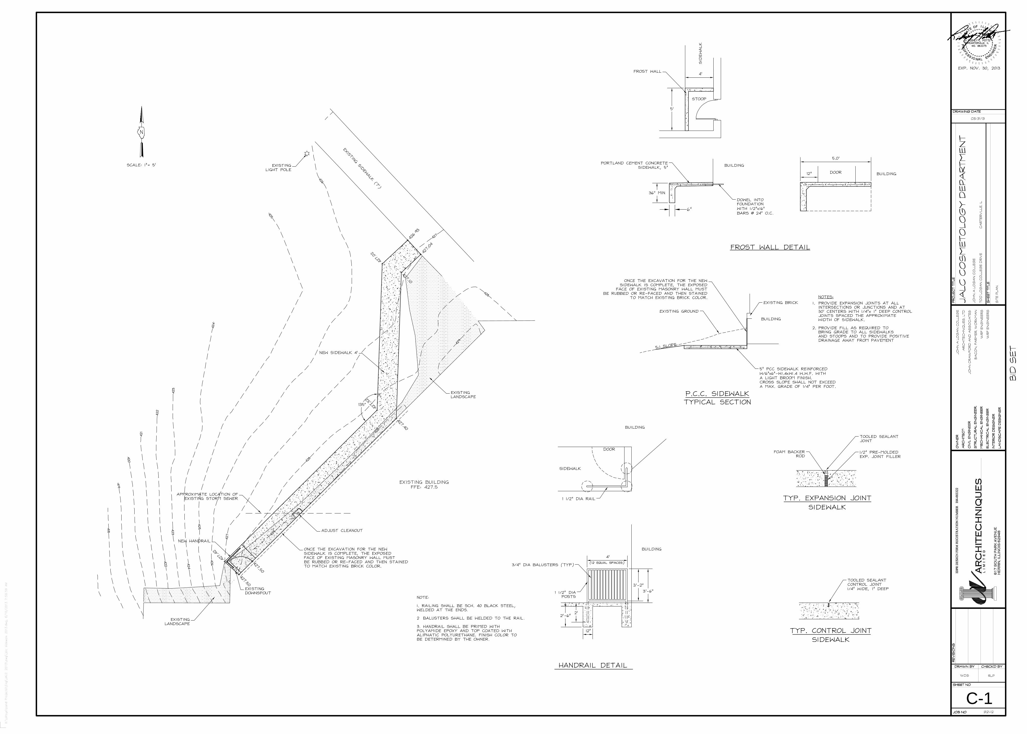
X:\altsys\
Land Projects\Eng\JA
LC 2013\dwg\jalc sidewalk 2013.dwg, 6/10/2013 7:59:59 AM
WR
F E
NG
INE
ER
S
WR
F E
NG
INE
ER
S
BA
CO
N, F
AR
ME
R, W
OR
KM
AN
JOH
N C
RA
WFO
RD
AN
D A
SS
OC
IATE
S
AR
CH
ITE
CH
NIQ
UE
S, L
TD
JOH
N A
LO
GA
N C
OLL
EG
E
SIT
E P
LAN
JOH
N A
LO
GA
N C
OLL
EG
E
700
LO
GA
N C
OLL
EG
E D
RIV
E
CA
RTE
RV
ILLE
, IL
JALC
CO
SM
ETO
LOG
Y D
EP
AR
TME
NT
05/31/13
RLPWDS
C-1921-12
BID
SE
T

4
A�7
5
A�7
212
STORAGESTORAGESTORAGESTORAGE
D214aCLASSROOMCLASSROOMCLASSROOMCLASSROOM
D214
OFFICEOFFICEOFFICEOFFICE
D216
CORRIDORCORRIDORCORRIDORCORRIDOR
D213
DISPENSORYDISPENSORYDISPENSORYDISPENSORY
D215
LAUNDRYLAUNDRYLAUNDRYLAUNDRY
D213a
ALCOVEALCOVEALCOVEALCOVE
D216a
8' �
1"
24' � 0" 8' � 0"
17' �
6 1/2
"
RAMP UP
SLOPE: 1:12
NEW CONCRETE RAMP
EXISTING RAMP UP
2' � 0"
EXISTING RAISED AREA
CONTRACTOR TO VERIFY
ELEVATION
2' � 0"
7' � 3" 8' � 4 1/2"
NEW RAISED FLOOR AREA
TO MATCH EXISTING ADJACENT
FLOOR ELEVATION.
CONTRACTOR TO VERIFY.
CLASSROOMCLASSROOMCLASSROOMCLASSROOM
D214
CORRIDORCORRIDORCORRIDORCORRIDOR
D213
STORAGESTORAGESTORAGESTORAGE
D214a
OFFICEOFFICEOFFICEOFFICE
D216
8' � 0"10' � 0"
10' � 0"
NEW 2'x2' FIRE RATED
ACCESS PANEL
INSTALLED IN EXISTING
STAIR
DROPPED HEAD
DROPPED HEAD
24' � 0"
SLOPE CEILING
WITH RAMP8' � 0"
FACIALFACIALFACIALFACIAL
D232
EXISTING BEAM WRAPPED IN NEW GYP AND
PAINTED. @ 7'�6" A.F.F. OR BOTTOM OF BEAM.
CONTRACTOR TO VERIFY.
9' � 0"
7' � 6"
2' �
0"
24' � 0" 8' � 0"
3" LIGHTWEIGHT CONCRETE
CONTINUOUS COMPACTED
GRAVEL OR SAND FILL
CONTRACTOR TO VERIFY
HEIGHT OF EXISTING
RAISED AREA AND MATCH
PROVIDE CUTOUT
OR TAPER TO MATCH
VA
RIE
S
3" LIGHTWEIGHT CONCRETE
W/ 6x6 W1.4xW1.4 W.W.F.
CONTINUOUS COMPACTED
GRAVEL OR SAND FILL
EXISTING SLAB
NEW WALL, RE: A�1 AND A�3 5/8" TREATED PLYWOOD TO TOP OF CONCRETE.
CONTRACTOR MAY USE NEW WALL
FRAMING WITH 5/8" PLYWOOD
AS CONCRETE FORMWORK
5/8" GYP BOARD FROM TOP OF CONCRETE
5' �
0"
5/8" GYP BOARD
2 1/2" METAL STUDS @ 16" O.C.
TO 5'�0" A.F.F.
EXISTING WALL TO REMAIN
WALL BASE, AS SCHEDULED
JOB NO.:JOB NO.:JOB NO.:JOB NO.:
SHEET NO.:SHEET NO.:SHEET NO.:SHEET NO.:
DRAWN BY:DRAWN BY:DRAWN BY:DRAWN BY: CHECK'D BY:CHECK'D BY:CHECK'D BY:CHECK'D BY:
RE
VIS
ION
S:
RE
VIS
ION
S:
RE
VIS
ION
S:
RE
VIS
ION
S:
PR
OJE
CT T
ITLE
:P
RO
JE
CT T
ITLE
:P
RO
JE
CT T
ITLE
:P
RO
JE
CT T
ITLE
:
SH
EE
T T
ITLE
:S
HE
ET T
ITLE
:S
HE
ET T
ITLE
:S
HE
ET T
ITLE
:
DRAWING DATE:DRAWING DATE:DRAWING DATE:DRAWING DATE:
AR
CH
ITE
CH
NIQ
UE
SA
RC
HIT
EC
HN
IQU
ES
AR
CH
ITE
CH
NIQ
UE
SA
RC
HIT
EC
HN
IQU
ES
L I M
I T
E
D
81
7 S
OU
TH
PA
RK
AV
EN
UE
HE
RR
IN,
ILL
INO
IS 6
29
48
IDP
R D
ES
IGN
FIR
M R
EG
IST
RA
TIO
N N
UM
BE
R: 1
84�0
03322
OW
NE
R:
OW
NE
R:
OW
NE
R:
OW
NE
R:
AR
CH
ITE
CT:
AR
CH
ITE
CT:
AR
CH
ITE
CT:
AR
CH
ITE
CT:
CIV
IL E
NG
INE
ER
:C
IVIL
EN
GIN
EE
R:
CIV
IL E
NG
INE
ER
:C
IVIL
EN
GIN
EE
R:
STR
UC
TU
RA
L E
NG
INE
ER
:S
TR
UC
TU
RA
L E
NG
INE
ER
:S
TR
UC
TU
RA
L E
NG
INE
ER
:S
TR
UC
TU
RA
L E
NG
INE
ER
:
ME
CH
AN
ICA
L E
NG
INE
ER
:M
EC
HA
NIC
AL E
NG
INE
ER
:M
EC
HA
NIC
AL E
NG
INE
ER
:M
EC
HA
NIC
AL E
NG
INE
ER
:
ELE
CTR
ICA
L E
NG
INE
ER
:E
LE
CTR
ICA
L E
NG
INE
ER
:E
LE
CTR
ICA
L E
NG
INE
ER
:E
LE
CTR
ICA
L E
NG
INE
ER
:
INTE
RIO
R D
ES
IGN
ER
:IN
TE
RIO
R D
ES
IGN
ER
:IN
TE
RIO
R D
ES
IGN
ER
:IN
TE
RIO
R D
ES
IGN
ER
:
LA
ND
SC
AP
E D
ES
IGN
ER
:LA
ND
SC
AP
E D
ES
IGN
ER
:LA
ND
SC
AP
E D
ES
IGN
ER
:LA
ND
SC
AP
E D
ES
IGN
ER
:
C:\U
sers
\lacey\D
ocum
ents
\JA
LC
Cosm
eto
logy C
ON
ST
RU
CT
ION
Colla
b �
Lacey.r
vt
921�12921�12921�12921�12
A�7
LBYLBYLBYLBY SBSSBSSBSSBS
06/10/1306/10/1306/10/1306/10/13
JA
LC
CO
SM
ETO
LO
GY
DE
PA
RTM
EN
T
70
0 L
OG
AN
CO
LLE
GE
DR
IVE
C
AR
TE
RV
ILLE
, IL
70
0 L
OG
AN
CO
LLE
GE
DR
IVE
C
AR
TE
RV
ILLE
, IL
70
0 L
OG
AN
CO
LLE
GE
DR
IVE
C
AR
TE
RV
ILLE
, IL
70
0 L
OG
AN
CO
LLE
GE
DR
IVE
C
AR
TE
RV
ILLE
, IL
JO
HN
A L
OG
AN
CO
LLE
GE
JO
HN
A L
OG
AN
CO
LLE
GE
JO
HN
A L
OG
AN
CO
LLE
GE
JO
HN
A L
OG
AN
CO
LLE
GE
AD
DE
ND
UM
1 �
PLA
NS
AN
D D
ETA
ILS
AD
DE
ND
UM
1 �
PLA
NS
AN
D D
ETA
ILS
AD
DE
ND
UM
1 �
PLA
NS
AN
D D
ETA
ILS
AD
DE
ND
UM
1 �
PLA
NS
AN
D D
ETA
ILS
JO
HN
A L
OG
AN
CO
LLE
GE
JO
HN
A L
OG
AN
CO
LLE
GE
JO
HN
A L
OG
AN
CO
LLE
GE
JO
HN
A L
OG
AN
CO
LLE
GE
AR
CH
ITE
CH
NIQ
UE
S, LTD
AR
CH
ITE
CH
NIQ
UE
S, LTD
AR
CH
ITE
CH
NIQ
UE
S, LTD
AR
CH
ITE
CH
NIQ
UE
S, LTD
JO
HN
CR
AW
FO
RD
AN
D A
SS
OC
IATE
SJO
HN
CR
AW
FO
RD
AN
D A
SS
OC
IATE
SJO
HN
CR
AW
FO
RD
AN
D A
SS
OC
IATE
SJO
HN
CR
AW
FO
RD
AN
D A
SS
OC
IATE
S
BA
CO
N, FA
RM
ER
, W
OR
KM
AN
BA
CO
N, FA
RM
ER
, W
OR
KM
AN
BA
CO
N, FA
RM
ER
, W
OR
KM
AN
BA
CO
N, FA
RM
ER
, W
OR
KM
AN
WR
F E
NG
INE
ER
SW
RF E
NG
INE
ER
SW
RF E
NG
INE
ER
SW
RF E
NG
INE
ER
S
WR
F E
NG
INE
ER
SW
RF E
NG
INE
ER
SW
RF E
NG
INE
ER
SW
RF E
NG
INE
ER
S
BID
SE
TSCALE:SCALE:SCALE:SCALE: 1/4" = 1'�0" 1/4" = 1'�0" 1/4" = 1'�0" 1/4" = 1'�0"A�7A�7A�7A�7
RAMP FLOOR PLAN1111
SCALE:SCALE:SCALE:SCALE: 1/4" = 1'�0" 1/4" = 1'�0" 1/4" = 1'�0" 1/4" = 1'�0"A�7A�7A�7A�7
REFLECTED CEILING PLAN @ RAMP AREA2222
SCALE:SCALE:SCALE:SCALE: 1/4" = 1'�0" 1/4" = 1'�0" 1/4" = 1'�0" 1/4" = 1'�0"A�7A�7A�7A�7
REFLECTED CEILING PLAN @ FACIAL D2323333
SCALE:SCALE:SCALE:SCALE: 1/4" = 1'�0" 1/4" = 1'�0" 1/4" = 1'�0" 1/4" = 1'�0"A�7A�7A�7A�7
RAMP SECTION4444
SCALE:SCALE:SCALE:SCALE: 1 1/2" = 1'�0" 1 1/2" = 1'�0" 1 1/2" = 1'�0" 1 1/2" = 1'�0"A�7A�7A�7A�7
RAMP DETAIL AT NEW WALL5555
SCALE:SCALE:SCALE:SCALE: 1" = 1'�0" 1" = 1'�0" 1" = 1'�0" 1" = 1'�0"A�7A�7A�7A�7
FURRING DETAIL @ EXISTING WALLS6666
NOTE:
THIS FURRING DETAIL IS USED ON THE EXISTING WALLS IN CLASSROOM
D238 AND HAIRSTYLING LAB D238a
WHERE NEW HAIRSTYLING STATIONS ARE NOTED TO ALLOW FOR NEW
ELECTRICAL SERVICE. CONTRACTOR PROVIDED BY BASE BID.

1/2"
3/4"
3/4"
1"
3/4"
1/2"
1/2"
1 1/2"
1/2"
1/2"2"2"
2"
4"
2"
4"
2"
3/4"
2"
1 1/2"
2"
1/2"
1/2"
2"
2"
CO
CO
CO
CO
4"
1/2"
2"
2"
1/2"
2"
4"
4"
3"
3"
2"
2"
4"
4"
4"
4"
2"
2"
2 1/2"
3"
3"
2"
2"
CDB KDW
AR
CH
ITE
CH
NIQ
UE
SL
I M
I T
E D
81
7 S
OU
TH
PA
RK
AV
EN
UE
HE
RR
IN,
ILL
INO
IS 6
29
48
IDPR
DES
IGN
FIR
M R
EGIS
TRA
TIO
N N
UM
BER
: 18
4-00
3322
W12-053
DATE: 05/30/13LICENSE EXPIRES: 11/30/13
PD-1 3/16" = 1'-0"
EXISTING PLUMBING PLAN-DENTALASSISTING AREA
PLUMBING LEGEND
DOMESTIC COLD WATER
DOMESTIC HOT WATER
GAS PIPING
SANITARY PIPING
FLOOR DRAIN
WATER CLOSET
SINK
LAVATORY
FD
CLEANOUT
ELECTRIC WATER COOLER
DOMESTIC HOT WATER RETURN
COMPRESSED AIR PIPING
TOP CONNECTION
BOTTOM CONNECTION
ELBOW DOWN
TEE UP
TEE DOWN
ELBOW UP
BALL VALVE
INDICATES CONNECTION POINT OF NEW TO EXISTING
VACUUM LINE

2"
2"
4"
1/2"
3/4"
SK-2SK-2
SK-3
SK-1
SK-2
FD-1
x2
LAV-1
LAV-1
COTF
1/2"
2" 2"
1/2"
2"
4"
4"
3"
3"
2"
2"
4"
4"
4"
4"
2"
2"
3"
2"
3"
2"
2"
CDB KDW
AR
CH
ITE
CH
NIQ
UE
SL
I M
I T
E D
81
7 S
OU
TH
PA
RK
AV
EN
UE
HE
RR
IN,
ILL
INO
IS 6
29
48
IDPR
DES
IGN
FIR
M R
EGIS
TRA
TIO
N N
UM
BER
: 18
4-00
3322
W12-053
DATE: 05/30/13LICENSE EXPIRES: 11/30/13
P-1
3/16" = 1'-0"
PLUMBING PLAN-DENTALASSISTING AREA
1. PROVIDE NEW 1/2" DOMESTIC COLD & HOT WATER LINE TO FIXTURE.
2. ROUTE NEW 3/4" DOMESTIC COLD & HOT WATER LINES ABOVE CEILING.
3. CONNECT NEW 3/4" DOMESTIC COLD & HOT WATER LINES ABOVE CEILING.
4. ROUTE NEW 2" WASTE APPROXIMATELY AS SHOWN.
5. PROVIDE NEW ISLAND VENT. SEE DETAIL 1/P-2.
6. APPROXIMATE POINT OF EXISTING TIE IN FOR SANITARY.
7. BASE BID: PROVIDE NEW SINK.
8. NOT USED.
9. PROVIDE NEW LINE SIZED BALL VALVE.
10. SINK PROVIDED AS PART OF DENTAL EQUIPMENT. PLUMBING CONNECTIONS DONE BY
PLUMBING WORK.
11. SEE SHEET A-1.0 AND A-1.2 FOR ALT. BID WORK ON SINKS.
12. NEW AIR COMPRESSOR AND VACUUM PUMP BY DENTAL EQUIPMENT SUPPLIER TO BE
INCLUDED IN BID. DENTAL EQUIPMENT SUPPLIER TO SIZE FOR 5 CHAIRS AND EQUIPMENT AS
INDICATED ON ALL PLANS.
13. ROUTE NEW COMPRESSED AIR IN SLAB TO DENTAL CHAIRS. ROUTE APPROXIMATELY AS
SHOWN BELOW SLAB. PROVIDE CONNECTION TO EACH CHAIR. PLUMBING CONTRACTOR TO
SAWCUT FLOOR AS NEEDED FOR NEW WORK. REPAIR FLOOR WITH NEW CONCRETE.
14. ROUTE NEW VACUUM IN SLAB TO DENTAL CHAIRS. ROUTE APPROXIMATELY AS SHOWN
BELOW SLAB. PROVIDE CONNECTION TO EACH CHAIR. PLUMBING CONTRACTOR TO SAWCUT
FLOOR AS NEEDED FOR NEW WORK. REPAIR FLOOR WITH NEW CONCRETE.
15. SANITARY PIPING IN FLOOR, BELOW SLAB.
16. TIE INTO EXISTING DOMESTIC COLD AND HOT WATER SUPPLY APPROXIMATELY WHERE
SHOWN ABOVE JANITOR CLOSET.
17. DROP DOMESTIC LINES IN WALL/CHASE TO BELOW FLOOR.
18. CONNECT TO EXISTING LINE ABOVE CEILING APPROXIMATELY HERE.
19. HATCHED AREA REPRESENTS APPROXIMATE AREA OF FLOOR SAWCUTTING. PLUMBING
WORK CONTRACTOR TO DETERMINE EXTENT OF SAWCUTTING AND PERFORM SUCH WORK.
20. PIPING DROP DOWN WALL.
PLUMBING NEW WORK KEYED " " NOTES (THIS SHEET ONLY):

8"Ø
7"Ø
1 1/4"
12"Ø
8"Ø
9"Ø
3/4"
2"
1"
3/4"
2"
2 1/2" 2 1/2"
2" 2"
2 1/2" 2 1/2"
3/4"
3/4"
3/4"
3/4"
7"Ø
7"Ø
7"Ø
1"
3/4"
2"
16"Ø
16"Ø
8"Ø
4"x4"
10"x8"
10"x6"
8"x6"
8"x6"
6"x6"
6"Ø
6"Ø
6"Ø
6"Ø
24"x24"
2"
2"
2 1/2"
18"Ø
6"Ø
6"Ø
6"x6"
10"Ø
8"Ø
10"Ø
10"Ø
8"Ø
10"Ø
24"Ø
18"Ø18"Ø
20"Ø
20"Ø
36"x24"
6"Ø
6"Ø
2"
2 1/2"
2"
2 1/2"
1/2"
1/2"
2 1/2"
1 1/2"
2 1/2"
12"Ø
12"Ø
10"Ø
10"Ø
18"Ø
16"Ø
10"Ø
10"Ø
12"Ø
12"Ø
3/4"
3/4"
6"Ø
5"Ø
6"Ø
5"Ø
10"Ø
10"Ø
8"Ø
8"Ø
8"Ø
8"Ø
3/4"
3/4" 3/4"
3/4"
3/4"
36"x72"
36"x48"
48"x36"
24"x24"
24"x24"
14"Ø24"x24"
16"Ø
10"Ø
10"Ø
12"Ø
5"Ø
5"Ø
6"Ø
8"Ø
8"Ø
7"Ø
8"Ø
7"Ø
8"Ø
1"
3"
1"
3/4"
3/4"
3/4"
1/2"
3/4"
3/4"
10"Ø
10"Ø
10"Ø
10"Ø
10"Ø
7"Ø
6"Ø
7"Ø
7"Ø
8"Ø
7"Ø
8"Ø
8"Ø
3/4"
1 1/4"
3"
3"
2 1/2"
1 1/4"3/4"
3/4"
3/4"
1 1/2"
12"Ø12"Ø
6"Ø
12"Ø
12"Ø
10"Ø
16"Ø
9"Ø
16"Ø
16"Ø
20"Ø
14"Ø
20"Ø
24"Ø
36"Ø
30"Ø
10"x6"
10"Ø
10"Ø
12"x6"
12"x10"
14"x10"
10"x6"
24"x24"
12"Ø
3/4"
1"
3/4"
24"x24" 24"x24"3/4"
10"Ø
9"Ø
9"Ø
9"Ø
9"Ø
12"Ø
12"Ø
30"Ø26"Ø
8"Ø
7"Ø
7"Ø
7"Ø
7"Ø
5"Ø
5"Ø
24"x24"
2 1/2"
1 1/2" 1 1/2"
3/4"3/4"
7"Ø
10"Ø
5"Ø
3/4"
3/4"
3/4"
3/4"
2"
1 1/2"
1 1/2"
1 1/4"
2 1/2"
2 1/2"
2 1/2"
1"
1"
1/2"
3/4"
3/4"
4"Ø
1"
120"x24"
24"x24"
UH-4
24"x24"
CDB KDW
AR
CH
ITE
CH
NIQ
UE
SL
I M
I T
E D
81
7 S
OU
TH
PA
RK
AV
EN
UE
HE
RR
IN,
ILL
INO
IS 6
29
48
phon
e: 6
18-9
42-6
918
fax
: 618
-942
-681
9em
ail:
gene
ral@
arch
itech
niqu
esltd
.com
web
site
: ww
w.a
rchi
tech
niqu
esltd
.com
SH
EE
T T
ITLE
:
PR
OJE
CT:
CHECK'D BY
SHEET NO.:
JOB NO.:
DRAWN BY:
RE
VIS
ION
S:
IDPR
DES
IGN
FIR
M R
EGIS
TRA
TIO
N N
UM
BER
: 18
4-00
3322
DRAWING DATE:
OW
NE
R:
AR
CH
ITE
CT:
CIV
IL E
NG
INE
ER
:M
EC
HA
NIC
AL
EN
GIN
EE
R:
ELE
CTR
ICA
L E
NG
INE
ER
:S
TRU
CTU
RA
L E
NG
INE
ER
:IN
TER
IOR
DE
SIG
NE
R:
...AD
DE
ND
A #
1
6-10
-13
...
AR
CH
ITE
CH
NIQ
UE
S, L
TD.
NO
NE
WR
F E
NG
INE
ER
SW
RF
EN
GIN
EE
RS
NO
NE
AR
CH
ITE
CH
NIQ
UE
S, L
TD.
RE
NO
VA
TIO
NS
FO
R:
921-12
700
LOG
AN
CO
LLE
GE
DR
IVE
05/30/13
JALC
CO
SM
ETO
LOG
Y D
EP
AR
TME
NT C
AR
TER
VIL
LE, I
L
W12-053
DATE: 05/30/13LICENSE EXPIRES: 11/30/13
EX
ISTI
NG
FLO
OR
PLA
N -
HV
AC

S-9 S-9
S-9 S-9
S-9
S-9
S-3
VAV-6
S-3
S-6
S-3
VAV-2
S-8S-8S-8
S-8 S-8
S-8
S-5 S-5
S-5
S-1
S-1
S-1
S-7
S-7
S-7
S-9
VAV-4
S-4
VAV-5
VAV-1
S-4
S-2
S-2
S-2
S-2
S-7 S-7
S-7S-7
S-7 S-7
R-2R-2
R-4 R-4
R-1
R-2
R-2
R-2
S-9
R-3
R-3
R-3
R-4
R-3
R-1
R-4
R-3
R-4
R-5
R-3
R-3
R-3
S-9
S-9
S-9
S-9
S-9
S-9
S-9
S-9
S-9
R-1
VAV-3
R-4
S-10
S-10
S-10S-10
S-10S-10
S-10S-10
S-10
S-10
S-10
S-10
R-4
R-3
R-4
R-4
S-1
CDB KDW
AR
CH
ITE
CH
NIQ
UE
SL
I M
I T
E D
81
7 S
OU
TH
PA
RK
AV
EN
UE
HE
RR
IN,
ILL
INO
IS 6
29
48
phon
e: 6
18-9
42-6
918
fax
: 618
-942
-681
9em
ail:
gene
ral@
arch
itech
niqu
esltd
.com
web
site
: ww
w.a
rchi
tech
niqu
esltd
.com
SH
EE
T T
ITLE
:
PR
OJE
CT:
CHECK'D BY
SHEET NO.:
JOB NO.:
DRAWN BY:
RE
VIS
ION
S:
IDPR
DES
IGN
FIR
M R
EGIS
TRA
TIO
N N
UM
BER
: 18
4-00
3322
DRAWING DATE:
OW
NE
R:
AR
CH
ITE
CT:
CIV
IL E
NG
INE
ER
:M
EC
HA
NIC
AL
EN
GIN
EE
R:
ELE
CTR
ICA
L E
NG
INE
ER
:S
TRU
CTU
RA
L E
NG
INE
ER
:IN
TER
IOR
DE
SIG
NE
R:
...AD
DE
ND
A #
1
6-10
-13
...
AR
CH
ITE
CH
NIQ
UE
S, L
TD.
NO
NE
WR
F E
NG
INE
ER
SW
RF
EN
GIN
EE
RS
NO
NE
AR
CH
ITE
CH
NIQ
UE
S, L
TD.
RE
NO
VA
TIO
NS
FO
R:
921-12
700
LOG
AN
CO
LLE
GE
DR
IVE
05/30/13
JALC
CO
SM
ETO
LOG
Y D
EP
AR
TME
NT C
AR
TER
VIL
LE, I
L
W12-053
DATE: 05/30/13LICENSE EXPIRES: 11/30/13
NE
W F
LOO
R P
LAN
- H
VA
C
M-1.0

2" 2"
4"
2"
2"
2"
3"
8"
2"
2"
2"
2"
2"
2"
2"
2"
2"
4"
4"
2"
3"
4"
4"
4"
4"
4"
2"
4"
4"
3"
8"
3"
3"
3"
4"
4"
2"
4"
2"
2"
3"
2"
2"
4"
4"
4"
4"
4"
CDB KDW
AR
CH
ITE
CH
NIQ
UE
SL
I M
I T
E D
81
7 S
OU
TH
PA
RK
AV
EN
UE
HE
RR
IN,
ILL
INO
IS 6
29
48
phon
e: 6
18-9
42-6
918
fax
: 618
-942
-681
9em
ail:
gene
ral@
arch
itech
niqu
esltd
.com
web
site
: ww
w.a
rchi
tech
niqu
esltd
.com
SH
EE
T T
ITLE
:
PR
OJE
CT:
CHECK'D BY
SHEET NO.:
JOB NO.:
DRAWN BY:
RE
VIS
ION
S:
IDPR
DES
IGN
FIR
M R
EGIS
TRA
TIO
N N
UM
BER
: 18
4-00
3322
DRAWING DATE:
OW
NE
R:
AR
CH
ITE
CT:
CIV
IL E
NG
INE
ER
:M
EC
HA
NIC
AL
EN
GIN
EE
R:
ELE
CTR
ICA
L E
NG
INE
ER
:S
TRU
CTU
RA
L E
NG
INE
ER
:IN
TER
IOR
DE
SIG
NE
R:
...AD
DE
ND
A #
1
6-10
-13
...
AR
CH
ITE
CH
NIQ
UE
S, L
TD.
NO
NE
WR
F E
NG
INE
ER
SW
RF
EN
GIN
EE
RS
NO
NE
AR
CH
ITE
CH
NIQ
UE
S, L
TD.
RE
NO
VA
TIO
NS
FO
R:
921-12
700
LOG
AN
CO
LLE
GE
DR
IVE
05/30/13
JALC
CO
SM
ETO
LOG
Y D
EP
AR
TME
NT C
AR
TER
VIL
LE, I
L
W12-053
DATE: 05/30/13LICENSE EXPIRES: 11/30/13
EX
ISTI
NG
FLO
OR
PLA
N -
SA
NIT
AR
Y

2"
3"
COTF
COTF
COTF
COTF
EXISTING
SANITARY LINE
EXISTING
VENT LINE
3"
2"
2"
2"
2"
2"
2"
2"
SK-3
SK-3
SK-3
SK-5
SK-5
SK-5
SK-5
WC-1
WC-1
LAV-1
LAV-1
SK-3
WM-1
SK-4
SK-4
SK-4
SK-4
SK-4
SK-4
SK-4
SK-3
2"
SK-4
SK-4
SK-4
SK-4
SK-4
SK-4
SK-4
SK-4
SK-4
SK-4
SK-4
SK-4
SK-4
SK-4
SK-4
SK-4
SK-4
SK-4
CDB KDW
AR
CH
ITE
CH
NIQ
UE
SL
I M
I T
E D
81
7 S
OU
TH
PA
RK
AV
EN
UE
HE
RR
IN,
ILL
INO
IS 6
29
48
phon
e: 6
18-9
42-6
918
fax
: 618
-942
-681
9em
ail:
gene
ral@
arch
itech
niqu
esltd
.com
web
site
: ww
w.a
rchi
tech
niqu
esltd
.com
SH
EE
T T
ITLE
:
PR
OJE
CT:
CHECK'D BY
SHEET NO.:
JOB NO.:
DRAWN BY:
RE
VIS
ION
S:
IDPR
DES
IGN
FIR
M R
EGIS
TRA
TIO
N N
UM
BER
: 18
4-00
3322
DRAWING DATE:
OW
NE
R:
AR
CH
ITE
CT:
CIV
IL E
NG
INE
ER
:M
EC
HA
NIC
AL
EN
GIN
EE
R:
ELE
CTR
ICA
L E
NG
INE
ER
:S
TRU
CTU
RA
L E
NG
INE
ER
:IN
TER
IOR
DE
SIG
NE
R:
...AD
DE
ND
A #
1
6-10
-13
...
AR
CH
ITE
CH
NIQ
UE
S, L
TD.
NO
NE
WR
F E
NG
INE
ER
SW
RF
EN
GIN
EE
RS
NO
NE
AR
CH
ITE
CH
NIQ
UE
S, L
TD.
RE
NO
VA
TIO
NS
FO
R:
921-12
700
LOG
AN
CO
LLE
GE
DR
IVE
05/30/13
JALC
CO
SM
ETO
LOG
Y D
EP
AR
TME
NT C
AR
TER
VIL
LE, I
L
W12-053
DATE: 05/30/13LICENSE EXPIRES: 11/30/13
NE
W F
LOO
R P
LAN
- S
AN
ITA
RY
P-1.0
PLUMBING NEW KEYED " " NOTES(THIS SHEET ONLY):
1. NEW SANITARY LINE FROM BACKWASH CHAIRS. CONFIRM FINAL CONNECTION
REQUIREMENTS WITH EQUIPMENT SUPPLIER AS PROVIDED BY OWNER. VENT AS
REQUIRED.
2. PROVIDE SANITARY CONNECTION TO EXISTING MAIN.
3. 3" SANITARY DOWN.
4. NEW DRAIN LINE FROM SINK. VENT AS REQUIRED.
5. PROVIDE NEW WATER CLOSET (WC-1) DRAIN AND VENT CONNECTION. RECONNECT TO
EXISTING.
6. PROVIDE NEW LAVATORY (LAV-1) DRAIN AND VENT CONNECTION.
7. EXISTING FLOOR DRAIN TO REMAIN.
8. PROVIDE NEW DRAIN AND VENT LINE FROM WASHING MACHINE BOX (WM-1).
9. PROVIDE NEW DRAIN AND VENT FROM ELECTRIC WATER COOLERS. RECONNECT TO
EXISTING DRAIN LINE FROM DEMO'D WASHING MACHINE BOX.
10. RECONNECT NEW SINK TO EXISTING SANITARY AND VENT.
11. HATCHED AREA REPRESENTS APPROXIMATE EXTENT OF FLOOR SAW CUTTING.
12. IN CEILING BELOW.

SK-3
EWC-1
SK-3
SK-3
SK-5
SK-5
SK-5
SK-5
UP FROM
BELOW
DROP DOWN
WALL TO
BELOW FLOOR
1/2" CW & HW
BELOW FLOOR
3/4" CW
3/4" HW
1/2" HWR
ABOVE
CEILING
3 EACH
2 EACH
2 EACH
3/4" CW
3/4" HW
ABOVE
CEILING
IN WALL
3 EACH
WC-1
WC-1
LAV-1
LAV-1
1/2" CW
1/2" HW
1" CW
1" HW
BELOW
FLOOR
1" CW
1" HW
BELOW
FLOOR
1-1/4" CW
1-1/4" HW
3/4" HWR
1-1/4" CW
1-1/4" HW
3/4" HWR
ABOVE
CEILING
3 EACH
2 EACH
2 EACH
2 EACH
3/4" CW
3/4" HW
SK-3
1/2" CW
1/2" HW
3/4" CW
3/4" HW
3/4" CW
3/4" HW
WM-1
SK-4
SK-3
DROP
DOWN
WALL
DROP DOWN WALL
TO BELOW FLOOR
DROP DOWN WALL
TO BELOW FLOOR
DROP
DOWN
WALL
CDB KDW
AR
CH
ITE
CH
NIQ
UE
SL
I M
I T
E D
81
7 S
OU
TH
PA
RK
AV
EN
UE
HE
RR
IN,
ILL
INO
IS 6
29
48
phon
e: 6
18-9
42-6
918
fax
: 618
-942
-681
9em
ail:
gene
ral@
arch
itech
niqu
esltd
.com
web
site
: ww
w.a
rchi
tech
niqu
esltd
.com
SH
EE
T T
ITLE
:
PR
OJE
CT:
CHECK'D BY
SHEET NO.:
JOB NO.:
DRAWN BY:
RE
VIS
ION
S:
IDPR
DES
IGN
FIR
M R
EGIS
TRA
TIO
N N
UM
BER
: 18
4-00
3322
DRAWING DATE:
OW
NE
R:
AR
CH
ITE
CT:
CIV
IL E
NG
INE
ER
:M
EC
HA
NIC
AL
EN
GIN
EE
R:
ELE
CTR
ICA
L E
NG
INE
ER
:S
TRU
CTU
RA
L E
NG
INE
ER
:IN
TER
IOR
DE
SIG
NE
R:
...AD
DE
ND
A #
1
6-10
-13
...
AR
CH
ITE
CH
NIQ
UE
S, L
TD.
NO
NE
WR
F E
NG
INE
ER
SW
RF
EN
GIN
EE
RS
NO
NE
AR
CH
ITE
CH
NIQ
UE
S, L
TD.
RE
NO
VA
TIO
NS
FO
R:
921-12
700
LOG
AN
CO
LLE
GE
DR
IVE
05/30/13
JALC
CO
SM
ETO
LOG
Y D
EP
AR
TME
NT C
AR
TER
VIL
LE, I
L
W12-053
DATE: 05/30/13LICENSE EXPIRES: 11/30/13
NE
W F
LOO
R P
LAN
- D
OM
ES
TIC
P-1.1