secondary unit substations—secondary below 1000 v
TRANSCRIPT
CA08104001E For more information, visit: www.eaton.com/consultants
April 2016
Contents
Secondary Unit Substations—Secondary Below 1000 V 14.0-1Sheet 14
i
ii
1
2
3
4
5
6
7
8
9
10
11
12
13
14
15
16
17
18
19
20
21
001
Seco
nd
ary
Un
it S
ub
stati
on
s—
Seco
nd
ary
Belo
w 1
000 V Secondary Unit Substations—Secondary Below 1000 V
Transformer Fluids and NEC Compliance
Transformer Product Selector . . . . . . . . . . . . . . . . . . . . . . . . . . . . . . . . 14.0-2
Transformer Cooling Classes . . . . . . . . . . . . . . . . . . . . . . . . . . . . . . . . . 14.0-3
Transformer Fluids Comparison . . . . . . . . . . . . . . . . . . . . . . . . . . . . . . 14.0-4
National Electrical Code (NFPA 70 NEC) Requirements. . . . . . . . . . . . 14.0-5
Product Overview
DOE 2016 Requirements . . . . . . . . . . . . . . . . . . . . . . . . . . . . . . . . . . . . . 14.0-9
Types of Distribution Systems . . . . . . . . . . . . . . . . . . . . . . . . . . . . . . . . 14.0-10
Cable Terminal Compartment . . . . . . . . . . . . . . . . . . . . . . . . . . . . . . . . 14.0-11
Type MVS Load Interrupter Switchgear . . . . . . . . . . . . . . . . . . . . . . . . 14.0-11
Metal-Enclosed Switchgear Assembly, Type MSB . . . . . . . . . . . . . . . . 14.0-11
Liquid-Filled Substation Transformers . . . . . . . . . . . . . . . . . . . . . . . . . 14.0-12
VPI/VPE Dry-Type Transformers. . . . . . . . . . . . . . . . . . . . . . . . . . . . . . . 14.0-19
Cast Coil Transformers . . . . . . . . . . . . . . . . . . . . . . . . . . . . . . . . . . . . . . 14.0-21
RESIBLOC Epoxy Cast Resin Transformers. . . . . . . . . . . . . . . . . . . . . . 14.0-23
Magnum DS Low Voltage Metal-Enclosed Switchgear . . . . . . . . . . . . 14.0-25
Pow-R-Line C Switchboards . . . . . . . . . . . . . . . . . . . . . . . . . . . . . . . . . . 14.0-25
Secondary Unit Substation Plug-and-Play . . . . . . . . . . . . . . . . . . . . . . 14.0-26
TC-100 Temp Controller . . . . . . . . . . . . . . . . . . . . . . . . . . . . . . . . . . . . . 14.0-27
Layout Dimensions
Composite Floor Plans . . . . . . . . . . . . . . . . . . . . . . . . . . . . . . . . . . . . . . 14.0-28
Substation with Air Terminal Chamber (ATC). . . . . . . . . . . . . . . . . . . . 14.0-32
Primary Switching Equipment . . . . . . . . . . . . . . . . . . . . . . . . . . . . . . . . 14.0-34
Transformers and Losses . . . . . . . . . . . . . . . . . . . . . . . . . . . . . . . . . . . . 14.0-35
Outdoor Secondary Equipment . . . . . . . . . . . . . . . . . . . . . . . . . . . . . . . 14.0-39
Technical Data
Transformers . . . . . . . . . . . . . . . . . . . . . . . . . . . . . . . . . . . . . . . . . . . . . . 14.0-41
Primary Equipment . . . . . . . . . . . . . . . . . . . . . . . . . . . . . . . . . . . . . . . . . 14.0-42
Secondary Equipment . . . . . . . . . . . . . . . . . . . . . . . . . . . . . . . . . . . . . . 14.0-47
Specifications
See Eaton’s Product Specification Guide, available on CD or on the Web.CSI Format: . . . . . . . . . . . . . . . . . . . . . . . . . . 1995 2010
Section 16311 Section 26 11 16.11
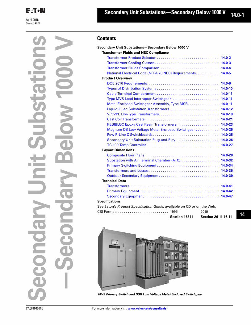
MVS Primary Switch and DSII Low Voltage Metal-Enclosed Switchgear

14.0-2
For more information, visit: www.eaton.com/consultants CA08104001E
April 2016
Secondary Unit Substations—Secondary Below 1000 V
Sheet 14
i
ii
1
2
3
4
5
6
7
8
9
10
11
12
13
14
15
16
17
18
19
20
21
Transformer Fluids and NEC ComplianceProduct Selection
002
Transformer Product SelectorTable 14.0-1. Transformer Product SelectorTransformer Maximum Voltage Available
kVA
CAG
Tab
Types Application
Considerations
Standards and
CertificationsPrimary Secondary
Unit Substation Transformer—Dry-TypeSecondary
Unit Substation (provides secondary system voltage)
34.5 kV 600 V 112.5 kVA–3750 kVA
14 VPI—An economical choice—suitable for most commercial appli-cations. Technology characterized by design flexibility and overload safety factor. Vacuum pressure impregnation with polyester resin.
Cast Coil—Lowest maintenance for most commercial and industrial applica-tions. By hermetically sealing the windings in epoxy, higher levels of performance and environmental robust-ness are achieved in high moisture, dust laden, and chemical contaminated environments.
RESIBLOC®—For applications with high shock and vibration or cold climates, RESIBLOC delivers a differentiated solution. Coils are insulated with epoxy and reinforced with glass-fiber rovings.
Transformer is part of a close-coupled assembly that includes both primary andsecondary equipment.
Explosion-resistant, fire-resistant and nonpolluting to the environment.
Neither containment nor fire suppression required for indoor installations.
ANSI C57.12.01/C57.12.91
UL® available
Seismic Zone 4 certification
Unit Substation Transformer—Liquid-FilledSecondary
Unit Substation (provides secondary system voltage)
34.5 kV 600 V 300 kVA–3750 kVA
14 Mineral Oil—Typical outdoor installation.
Silicone—Applied where flammability is a concern.
Envirotemp™ FR3™—Specified where flammability, clean-up and life extension are a concern.
Transformer is part of a close-coupled assembly that may include both primary and secondary equipment.
High short-circuit strength.
Sealed tank design is impervious to the environment.
Smaller footprint, greater efficiency, nonpolluting to the environment when filled with Envirotemp™ FR3™
Complies with ANSI C57.12.00 and C57.12.90, CSA®–88
UL, FM available
Seismic Zone 4 certification
CA08104001E For more information, visit: www.eaton.com/consultants
14.0-3April 2016
Secondary Unit Substations—Secondary Below 1000 V
Sheet 14
i
ii
1
2
3
4
5
6
7
8
9
10
11
12
13
14
15
16
17
18
19
20
21
Transformer Fluids and NEC ComplianceCooling Classes
003
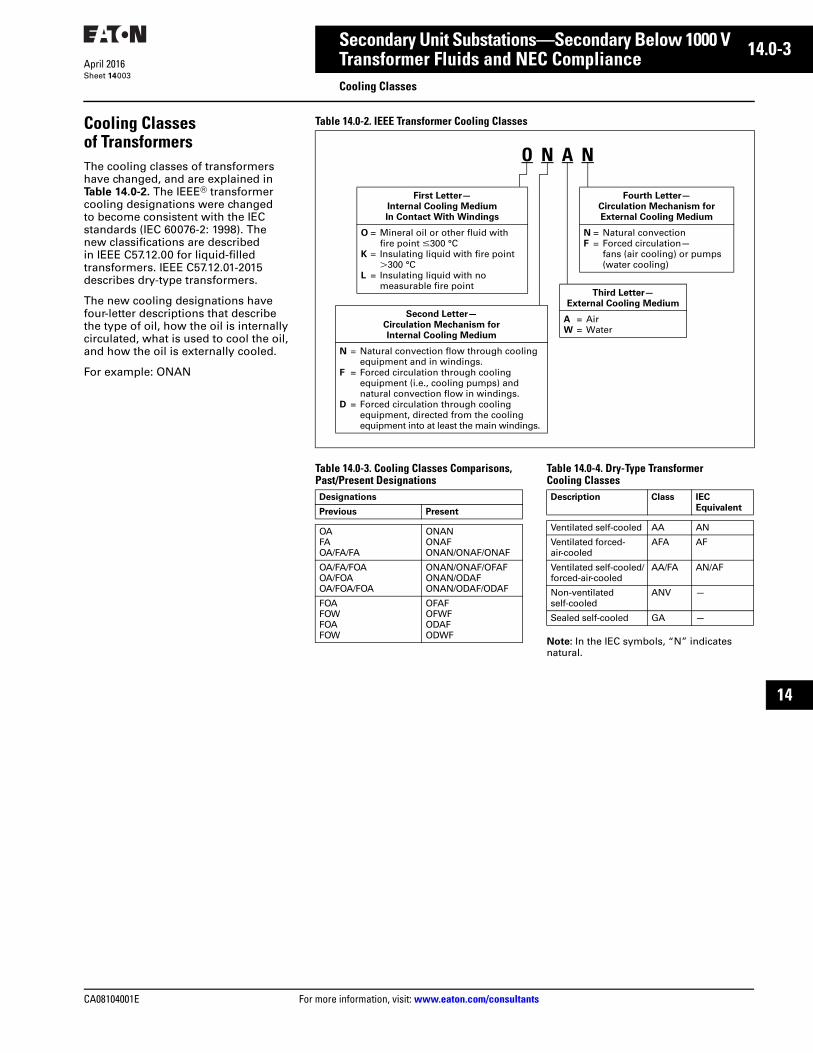
Cooling Classes of TransformersThe cooling classes of transformers have changed, and are explained in Table 14.0-2. The IEEE® transformer cooling designations were changed to become consistent with the IEC standards (IEC 60076-2: 1998). The new classifications are described in IEEE C57.12.00 for liquid-filled transformers. IEEE C57.12.01-2015 describes dry-type transformers.
The new cooling designations have four-letter descriptions that describe the type of oil, how the oil is internally circulated, what is used to cool the oil, and how the oil is externally cooled.
For example: ONAN
Table 14.0-2. IEEE Transformer Cooling Classes
Table 14.0-3. Cooling Classes Comparisons, Past/Present Designations
Table 14.0-4. Dry-Type Transformer Cooling Classes
Note: In the IEC symbols, “N” indicates natural.
O N A N
First Letter—
Internal Cooling Medium
In Contact With Windings
O = Mineral oil or other fluid withfire point m300 °C
K = Insulating liquid with fire pointL300 °C
L = Insulating liquid with no measurable fire point
Second Letter—
Circulation Mechanism for
Internal Cooling Medium
N = Natural convection flow through coolingequipment and in windings.
F = Forced circulation through coolingequipment (i.e., cooling pumps) andnatural convection flow in windings.
D = Forced circulation through coolingequipment, directed from the coolingequipment into at least the main windings.
Third Letter—
External Cooling Medium
A = AirW = Water
Fourth Letter—
Circulation Mechanism for
External Cooling Medium
N = Natural convectionF = Forced circulation—
fans (air cooling) or pumps(water cooling)
Designations
Previous Present
OAFAOA/FA/FA
ONANONAFONAN/ONAF/ONAF
OA/FA/FOAOA/FOAOA/FOA/FOA
ONAN/ONAF/OFAFONAN/ODAFONAN/ODAF/ODAF
FOAFOWFOAFOW
OFAFOFWFODAFODWF
Description Class IEC
Equivalent
Ventilated self-cooled AA AN
Ventilated forced-air-cooled
AFA AF
Ventilated self-cooled/forced-air-cooled
AA/FA AN/AF
Non-ventilated self-cooled
ANV —
Sealed self-cooled GA —

14.0-4
For more information, visit: www.eaton.com/consultants CA08104001E
April 2016
Secondary Unit Substations—Secondary Below 1000 V
Sheet 14
i
ii
1
2
3
4
5
6
7
8
9
10
11
12
13
14
15
16
17
18
19
20
21
Transformer Fluids and NEC ComplianceFluids Comparison
004
Transformer Fluids ComparisonTable 14.0-5. Fluid Advantages and Disadvantages
Table 14.0-6. Fluid Properties Comparison
Advantages Disadvantages
Mineral Oil■ Low transformer cost■ Good dielectric performance■ Low maintenance cost■ Good heat dissipation■ Good cold climate performance■ Preventative maintenance—DGA historical data available
■ Higher installation cost■ Potential vaults required for indoor installations per NEC®
low fire point—160 °C■ l30% Biodegradability
Silicone Fluid■ Low heat release■ Reduced smoke■ Low flame■ Self extinguishing■ Good dielectric performance■ Low toxicity■ Moderate viscosity■ High stability
■ Non-biodegradable■ Not suitable for use with internal Bay-O-Net fuses■ Transformer cost■ Disposal cost■ Viton gaskets required■ Retrofil applications■ High transformer cost■ High moisture absorption
Environmentally Friendly Fluids■ High fire point—360 °C■ High flash point—330 °C■ Compatible with mineral oil■ Excellent retrofil fluid (compatible with oil up to a 10% mixture)■ Excellent dielectric performance■ 99% biodegradable■ Renewable resource■ Greater tolerance to moisture■ Excellent switching medium■ Excellent cold weather performance■ Significant extension of transformer insulation life
■ Transformer cost (lower than silicone fluid)■ Pour point (–15 °C to –25 °C) transformer energized with full load with
top oil temperature at –50 °C with no dielectric problems—no crystals formed at –68 °C
Air■ Non-flammable■ No fluid analysis necessary■ Zero environmental impact
■ Transformer cost (oil is better dielectric than air)
Property Mineral
Oil
Silicone
Fluid
Environmentally Friendly
Fluids
Specific gravityFlash point °CFire point °C
0.91145160
0.96300330
0.91330360
Viscosity (cSt.) 100 °C40 °C0 °C
31276
163890
1045300
Pour point °CDielectric strength, kVDissipation factor (%) 25 °C
–40300.05
–554.30.01
–15–25490.025–0.05
PermittivityResistivityOxidation inhibitorBiodegradability
2.21013
Optionall30%
2.71014
No0%
3.11013
Required99%

CA08104001E For more information, visit: www.eaton.com/consultants
14.0-5April 2016
Secondary Unit Substations—Secondary Below 1000 V
Sheet 14
i
ii
1
2
3
4
5
6
7
8
9
10
11
12
13
14
15
16
17
18
19
20
21
Transformer Fluids and NEC ComplianceNEC Requirements
005
NEC Requirement Guidelines for the Installation of Transformers
NEC (NFPA) RecognitionThese guidelines focus on the requirements of Article 450 of the National Electrical Code® (NEC®). Articles 450.21 and 22 describe the installation of dry-type transformers; Article 450.23 describes the installation of less-flammable liquid insulated transformers; and Articles 450.26 and 27 describe the installation of mineral-insulated transformers. Typical applications of fire concern include installations indoor, on rooftops, near buildings, bush and forest fire prone areas, and in pedestrian traffic areas.
NEC Requirements
Mineral-Oil Insulated TransformersPer NEC 450.27 for mineral oil insulated transformers installed outdoors, in cases where the transformer installa-tion presents a fire hazard, one or more of the following safeguards shall be applied according to the degree of hazard involved:
1. Space separation
2. Fire-resistant barriers
3. Automatic fire suppression systems
4. Enclosures that confine the oil of a ruptured transformer tank
Per NEC 450.26, mineral oil insulated transformers installed indoors shall be installed in a 3-hour rated vault per Article 450, Part III.
Mineral oil insulated transformers are most commonly installed outdoors.
Dry-Type TransformersInformation regarding installation of dry-type transformers indoors is referenced from NEC 450.21. According to NEC Article 450.21, dry-type trans-formers that are completely enclosed, excluding ventilating openings, may be installed indoors without further requirements. The only considerationis allowing 6.00 inches minimum clearance on the front and rear to ensure proper ventilation.
Open ventilated dry transformers must either have space separation of 6 feet horizontally or 12 feet vertically from combustible material, have a fire resis-tant heat insulating barrier between the transformer and combustible material or be installed in a transformer room of fire resistant construction. Dry-type transformers rated over 35,000 volts shall be installed in a vault complying with Part III of Article 450.
Per Article 450.22, dry-type transformers installed outdoors shall have a weatherproof enclosure. Dry-type transformers are most commonly installed indoors.
Less-Flammable Liquid Insulated Transformers Less-flammable liquids, also known as high fire point liquids, are transformer dielectric coolants that have a minimum fire point of 300 ºC. Commonly used less-flammable fluids include dimethysiloxane, and ester-based fluids. Two Nationally Recognized Testing Laboratories (NRTL); Underwriters Laboratories (UL®) and FM Global (FM) currently list less-flammable liquids. They also list less-flammable liquid-filled transformers.
Less-flammable liquid-filled transformers were formally recognized by the NEC for indoor installation in 1978. In 1990, the NEC integrated specific less-flammable transformer requirements for outdoor installations in Article 450.23, in effect recognizing less-flammable transformers as inherently safer than conventional oil-filled transformers. Less-flammable transformers, long recognized as an additional safeguard for indoor installations, are becoming increas-ingly recognized for outdoor applica-tions as well. Less-flammable liquid insulated transformers are commonly installed either indoors or outdoors.
The requirements and options for the different types of indoor and outdoor installations of less-flammable liquid-insulated transformers per NEC 450.23 are outlined in Table 14.0-7. These guidelines also summarize the UL Classification and FM Approval installation requirements for less-flammable fluids referred to as “listing” requirements in NEC 450.23.
Outdoor installations may be made simpler by utilizing a less-flammable fluid in lieu of mineral oil per NEC 450.23 part B. Less-flammable liquid-filled transformers shall be permitted to be installed outdoors, attached to, adjacent to, or on the roof of buildings, where the building is a type I or II (non-combustible) construction and the installation shall comply with all restrictions provided for in the listing of the liquid. Installations unable to comply with these requirements shall comply with Article 450.27.
14.0-6
For more information, visit: www.eaton.com/consultants CA08104001E
April 2016
Secondary Unit Substations—Secondary Below 1000 V
Sheet 14
i
ii
1
2
3
4
5
6
7
8
9
10
11
12
13
14
15
16
17
18
19
20
21
Transformer Fluids and NEC ComplianceNEC Requirements
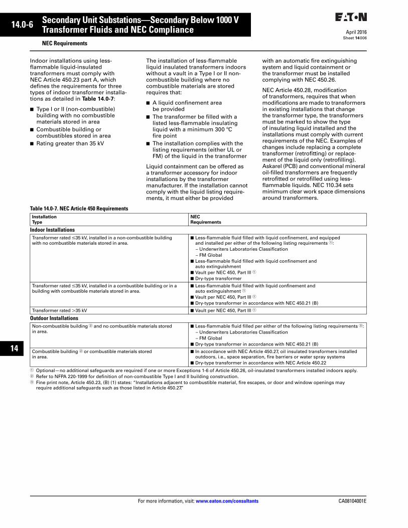
006
Indoor installations using less-flammable liquid-insulated transformers must comply with NEC Article 450.23 part A, which defines the requirements for three types of indoor transformer installa-tions as detailed in Table 14.0-7:
■ Type I or II (non-combustible) building with no combustible materials stored in area
■ Combustible building or combustibles stored in area
■ Rating greater than 35 kV
The installation of less-flammable liquid insulated transformers indoors without a vault in a Type I or II non-combustible building where no combustible materials are stored requires that:
■ A liquid confinement area be provided
■ The transformer be filled with a listed less-flammable insulating liquid with a minimum 300 ºC fire point
■ The installation complies with thelisting requirements (either UL or FM) of the liquid in the transformer
Liquid containment can be offered as a transformer accessory for indoor installations by the transformer manufacturer. If the installation cannot comply with the liquid listing require-ments, it must either be provided
with an automatic fire extinguishing system and liquid containment or the transformer must be installed complying with NEC 450.26.
NEC Article 450.28, modification of transformers, requires that when modifications are made to transformers in existing installations that change the transformer type, the transformers must be marked to show the type of insulating liquid installed and the installations must comply with current requirements of the NEC. Examples of changes include replacing a complete transformer (retrofitting) or replace-ment of the liquid only (retrofilling). Askarel (PCB) and conventional mineral oil-filled transformers are frequently retrofitted or retrofilled using less-flammable liquids. NEC 110.34 sets minimum clear work space dimensions around transformers.
Table 14.0-7. NEC Article 450 Requirements
1 Optional—no additional safeguards are required if one or more Exceptions 1-6 of Article 450.26, oil-insulated transformers installed indoors apply.2 Refer to NFPA 220-1999 for definition of non-combustible Type I and II building construction.3 Fine print note, Article 450.23, (B) (1) states: “Installations adjacent to combustible material, fire escapes, or door and window openings may
require additional safeguards such as those listed in Article 450.27.”
Installation
Type
NEC
Requirements
Indoor InstallationsTransformer rated m35 kV, installed in a non-combustible building with no combustible materials stored in area.
■ Less-flammable fluid filled with liquid confinement, and equipped and installed per either of the following listing requirements 1:– Underwriters Laboratories Classification– FM Global
■ Less-flammable fluid filled with liquid confinement and auto extinguishment
■ Vault per NEC 450, Part III 1
■ Dry-type transformer
Transformer rated m35 kV, installed in a combustible building or in a building with combustible materials stored in area.
■ Less-flammable fluid filled with liquid confinement and auto extinguishment 1
■ Vault per NEC 450, Part III 1
■ Dry-type transformer in accordance with NEC 450.21 (B)
Transformer rated L35 kV ■ Vault per NEC 450, Part III 1
Outdoor InstallationsNon-combustible building 2 and no combustible materials stored in area.
■ Less-flammable fluid filled per either of the following listing requirements 3:– Underwriters Laboratories Classification– FM Global
■ Dry-type transformer in accordance with NEC 450.21 (B)
Combustible building 2 or combustible materials stored in area.
■ In accordance with NEC Article 450.27, oil insulated transformers installed outdoors, i.e., space separation, fire barriers or water spray systems
■ Dry-type transformer in accordance with NEC Article 450.22

CA08104001E For more information, visit: www.eaton.com/consultants
14.0-7April 2016
Secondary Unit Substations—Secondary Below 1000 V
Sheet 14
i
ii
1
2
3
4
5
6
7
8
9
10
11
12
13
14
15
16
17
18
19
20
21
Transformer Fluids and NEC ComplianceNEC Requirements
007
Underwriters Laboratories RequirementsThe UL Classification of less-flammable liquids per the NEC Article 450.23 for three-phase 45–10,000 kVA transformers requires transformer fluid that will be UL Classified complying with the following transformer requirements:
■ Transformers be equipped with tanks capable of withstanding 12 psig minimum without rupture
■ Transformers be equipped with pressure relief devices with minimum pressure relief capacity per the UL Classification marking
Note: Refer to Table 14.0-9.
■ Transformer primaries be protected with overcurrent protection options per the UL Classification marking
Transformers will be supplied with appropriate pressure withstand and pressure relief when UL Classification is specified. Overcurrent protection may be supplied integral to the transformer or via switchgear feeding the transformer.
Figure 14.0-1. FM Global Recommended Construction for Transformer Buildings and Rooms
Table 14.0-8. Construction Features
1 No mineral oil-filled bushings, tap changers or other mineral oil-filled accessories.2 Refer to FM Global DS 5-4 Section 2.2.3.4 for protection of other combustibles other than
transformer liquids.3 FM Global DS 5-4 Section 3.3 describes FM Approved and equivalent transformers
(also described on 17.0-7).4 Provide liquid spill containment in accordance with DS 5-4 Section 2.2.1.5.5 Automatic sprinklers, foam water sprinklers or water mist. Also provide emergency drainage
for sprinkle discharge per DS 5-4 Section 2.2.1.6.6 Subdivide room or building with 3-hour rated construction for each transformer if multiple
transformers are present.
1
2
43
Main Building(Plan View)
1: Detached building2: Outside room with direct access from outside only3, 4: Inside room with direct access from outside onlySee Table 14.0-8 for construction features.
Transformer
Type
Fluid
Type
Fluid Volume
in Largest
Transformer
Room or
Building
Fire Rating
Fire Protection
for Transformer
Liquids
Dry or gas insulated 1
N/A N/A Noncombustible None 2
FM approved or equivalent 3
FM approved liquids
Any 4 Noncombustible None 2
Non-approvedtransformer
FM approved liquids
Any 4 1-hour fire-rated None 2
Noncombustible Per Section 2.2.3 5
Non-approved liquids
Less than 100 gal (380 L) 4
1-hour fire-rated None 2
More than 100 gal (380 L) 4
3-hour fire-rated with subdivisions if multiple transformers 6
None 2
3-hour fire-rated with multiple transformers and no subdivision
Per Section 2.2.3 5
1-hour fire-rated with single transformer
Per Section 2.2.3 5
FM Approved TransformerLess-flammable liquid-filled transformers rated 5–10,000 kVA must be equipped with specific design and protection features to be FM approved or equivalent. Key characteristics of this protection system are fire properties of the liquid, the ability to mechanically withstand pressure generated by a low-level electrical fault and the ability of electrical protection to clear a fault before tank rupture. According to FM approval Standard 3990, the key protection features are as listed below. Refer to the FM standard for complete requirements:
■ The transformer tank rupture strength shall be a minimum of 15 psi for rectangular and 20 psi for cylindrical tanks. All transformer tanks shall be designed to withstand a pressure of 7 psi without perma-nent distortion. The transformer tank shall be provided with a pressure relief device to vent internal over-pressures. The device must be capable of venting a minimum specified flow rate, based on the kVA as noted in Table 14.0-9 Section 2.3.3 of the FM approval Standard 3990. Proper pressure venting coordinated with proper tank pressure withstand rating has proven highly effective in preventing tank rupture from overpressure due to internal fault currents below the trip rating of primary circuit current limiting fuses
■ The transformer is filled with an FM Approved less-flammable fluid to reduce the probability of ignition to the liquid. Less-flammable fluids, also known as high fire point or fire-resistant liquids, are dielectric coolants that have a minimum fire point of 300 °C (572 °F) per the ASTM D92 Cleveland Open Cup test method
Note: For a listing of FM-approved less-flammable fluids, refer to Factory Mutual Research Approval Guide P7825.

14.0-8
For more information, visit: www.eaton.com/consultants CA08104001E
April 2016
Secondary Unit Substations—Secondary Below 1000 V
Sheet 14
i
ii
1
2
3
4
5
6
7
8
9
10
11
12
13
14
15
16
17
18
19
20
21
Transformer Fluids and NEC ComplianceNEC Requirements
008
■ The primary circuit shall have overcurrent protection that limits the let-through current (I2t) to a specified maximum value as listed in Table 14.0-10 and in Section 2.3.5 of the FM approval Standard 3990. Current-limiting fusing and its functional equivalents are designed to interrupt a high current internal fault before the tank withstand pressure level is reached. If protec-tion is designed to vent gas during operation, such as with expulsion fuses, this protection shall be located outside the transformer tank. Certain exceptions apply and permit expulsion fusing to be mounted in the tank if in series and properly coordinated with current limiting fusing
■ The transformer shall have an additional nameplate with the FM approval mark with the following data: tank pressure rating, fuse part number, pressure relief device part number, and requirements particular to the type of installation Transformer manufacturers instructed to design and build transformers per the UL Classification Mark (refer to UL Classification Mark in 17.0-5) the utilized less-flammable fluid should be designed accordingly. If primary overcurrent protection is specified as integral to the transformer, trans-former manufacturers should also comply. Otherwise, meeting FM Approval requirements will be the responsibility of the user.
■ For grounded wye secondary wind-ings of 150 V or more and rated at 1000 or more nominal amperes, a notification tag shall be provided by the manufacturer, secured to the low voltage neutral bushing, advising that the transformer installation requires ground fault relay protec-tion prior to energization (if not installed at time of manufacturing)
■ Indoor units greater than 500 kVA and outdoor units greater than 2500 kVA shall be equipped with alarm contacts on the pressure relief device. Transformer above 2500 kVA in all locations shall be equipped with a rapid rise relay
■ Three-phase pad-mounted and substation transformers shall be equipped with an oil level gauge. Additionally, all transformers rated 750 kVA or higher shall be equipped with a liquid temperature indicator and pressure-vacuum gauge
■ Transformers shall be capable of maintaining rated basic lightning impulse insulation level (BIL) at a minimum tilt of 1.5º from vertical
Transformers will be supplied with appropriate pressure withstand, pressure relief and other devices noted above when FM Approval is specified. The required overcurrent protection may be supplied integral to the trans-former or via switchgear feeding the transformer as noted above depending how it is specified by the user.
Additional FM Global Requirements Applying to All Indoor TransformersIndoor installation requirements, according to FM loss prevention data (LPD) 5-4, consist of requirements for all transformer types and likely would apply to those who are FM insured or those choosing FM Approval as their means to comply with the listing restrictions of NEC 450.23 for less-flammable insulated transformers.
If transformers cannot be located out-doors, provide a detached dedicated building or room with location and construction safeguards as noted in Figure 14.0-1 and Figure 14.0-9.
Arrange transformer rooms for direct access only from outdoors or install transformer(s) in a detached building of the following construction:
■ Dry-type, gas-insulated and FM approved or equivalent less-flammable liquid insulated transformers:❑ Liquid containment❑ Noncombustible building
construction■ Non-FM Approved transformers
with FM Approved transformer fluids:❑ Liquid containment❑ 1-hour fire-rated construction if
no fire protection is provided, or❑ Noncombustible construction if
fire protection (automatic sprin-klers, FM Approved foam-water sprinklers, or FM Approved water mist) is also provided
■ Transformers with no more than 100 gal (380 L) of non-approved fluids: 1-hour fire-rated construction
■ Transformers with greater than 100 gal (380 L) of non-approved fluids: ❑ 3-hour fire-rated construction.❑ If multiple transformers are
present, also provide one of the following:– 3-hour fire-rated subdivisions
for each transformer, or– Automatic sprinklers, FM
approved foam-water or– FM approved water mist
protection per Section 2.2.3
(Non-approved fluids generally applies to mineral oil.)
Table 14.0-9. FM and UL Pressure Relief Device Required Ratings
Note: For kVA ratings not listed, use next highest rating in table.
Table 14.0-10. FM and UL Maximum I2t Let-Through Required Ratings
Note: For kVA ratings not listed, use next lowest rating in table.
kVA Rating Flow Rate
SCFM at 15PSI
(103 kPa)Three-
Phase
Single-
Phase
112.5150300
37.550
100
3550
100
10002000
10,000
333667
3333
350700
5000
kVA Rating Current
Limiting
Fusing
Other
ProtectionThree-
Phase
Single-
Phase
4575
1525
500,000500,000
700,000800,000
112.5150225
37.55075
550,000600,000650,000
900,0001,000,0001,200,000
300500750
100167250
750,000900,000
1,100,000
1,400,0001,900,0002,200,000
100015002000
333500667
1,250,0001,500,0001,750,000
3,400,0004,500,0006,000,000
250030003750
83310001250
2,000,0002,250,0002,500,000
7,500,0009,000,000
11,000,000
50007500
10,000
166725003333
3,000,0003,000,0003,000,000
14,000,00014,000,00014,000,000
CA08104001E For more information, visit: www.eaton.com/consultants
14.0-9April 2016
Secondary Unit Substations—Secondary Below 1000 V
Sheet 14
i
ii
1
2
3
4
5
6
7
8
9
10
11
12
13
14
15
16
17
18
19
20
21
Product OverviewDOE Requirements
009
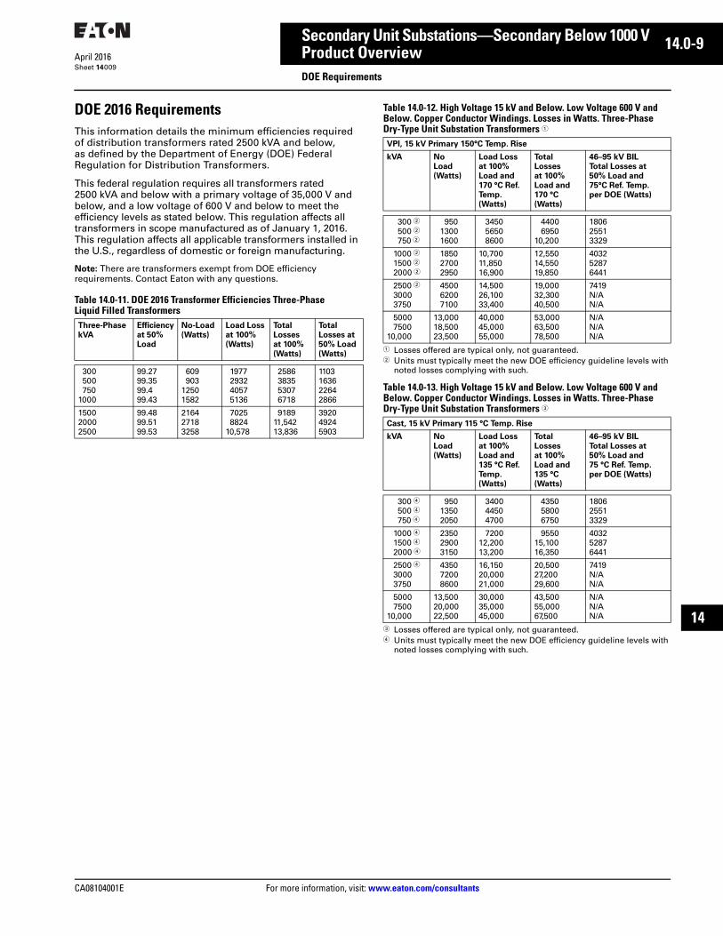
DOE 2016 RequirementsThis information details the minimum efficiencies required of distribution transformers rated 2500 kVA and below, as defined by the Department of Energy (DOE) Federal Regulation for Distribution Transformers.
This federal regulation requires all transformers rated 2500 kVA and below with a primary voltage of 35,000 V and below, and a low voltage of 600 V and below to meet the efficiency levels as stated below. This regulation affects all transformers in scope manufactured as of January 1, 2016. This regulation affects all applicable transformers installed in the U.S., regardless of domestic or foreign manufacturing.
Note: There are transformers exempt from DOE efficiency requirements. Contact Eaton with any questions.
Table 14.0-11. DOE 2016 Transformer Efficiencies Three-Phase Liquid Filled Transformers
Table 14.0-12. High Voltage 15 kV and Below. Low Voltage 600 V and Below. Copper Conductor Windings. Losses in Watts. Three-Phase Dry-Type Unit Substation Transformers 1
1 Losses offered are typical only, not guaranteed.2 Units must typically meet the new DOE efficiency guideline levels with
noted losses complying with such.
Table 14.0-13. High Voltage 15 kV and Below. Low Voltage 600 V and Below. Copper Conductor Windings. Losses in Watts. Three-Phase Dry-Type Unit Substation Transformers 3
3 Losses offered are typical only, not guaranteed.4 Units must typically meet the new DOE efficiency guideline levels with
noted losses complying with such.
Three-Phase
kVA
Efficiency
at 50%
Load
No-Load
(Watts)
Load Loss
at 100%
(Watts)
Total
Losses
at 100%
(Watts)
Total
Losses at
50% Load
(Watts)
300500750
1000
99.2799.3599.499.43
609903
12501582
1977293240575136
2586383553076718
1103163622642866
150020002500
99.4899.5199.53
216427183258
70258824
10,578
918911,54213,836
392049245903
VPI, 15 kV Primary 150°C Temp. Rise
kVA No
Load
(Watts)
Load Loss
at 100%
Load and
170 °C Ref.
Temp.
(Watts)
Total
Losses
at 100%
Load and
170 °C
(Watts)
46–95 kV BIL
Total Losses at
50% Load and
75°C Ref. Temp.
per DOE (Watts)
300 2500 2750 2
95013001600
345056508600
44006950
10,200
180625513329
1000 21500 22000 2
185027002950
10,70011,85016,900
12,55014,55019,850
403252876441
2500 230003750
450062007100
14,50026,10033,400
19,00032,30040,500
7419N/AN/A
50007500
10,000
13,00018,50023,500
40,00045,00055,000
53,00063,50078,500
N/AN/AN/A
Cast, 15 kV Primary 115 °C Temp. Rise
kVA No
Load
(Watts)
Load Loss
at 100%
Load and
135 °C Ref.
Temp.
(Watts)
Total
Losses
at 100%
Load and
135 °C
(Watts)
46–95 kV BIL
Total Losses at
50% Load and
75 °C Ref. Temp.
per DOE (Watts)
300 4500 4750 4
95013502050
340044504700
435058006750
180625513329
1000 41500 42000 4
235029003150
720012,20013,200
955015,10016,350
403252876441
2500 430003750
435072008600
16,15020,00021,000
20,50027,20029,600
7419N/AN/A
50007500
10,000
13,50020,00022,500
30,00035,00045,000
43,50055,00067,500
N/AN/AN/A

14.0-10
For more information, visit: www.eaton.com/consultants CA08104001E
April 2016
Secondary Unit Substations—Secondary Below 1000 V
Sheet 14
i
ii
1
2
3
4
5
6
7
8
9
10
11
12
13
14
15
16
17
18
19
20
21
Product OverviewGeneral Description
010
General Description
DefinitionA secondary unit substation is a close-coupled assembly consisting of enclosed primary high voltage equipment, three-phase power transformers, and enclosed secondary low voltage equipment. The following electrical ratings are typical:
■ Primary voltage: 2.4–38 kV■ Transformer kVA: 300–3750■ Secondary voltage: 208, 240, 480
or 600 V (maximum)
A secondary unit substation is defined in the following standards:
■ NEMA® Standard No. 210■ IEEE Standard No. 100
AdvantagesAs a result of locating power transformers and their close-coupled secondary switchboards as close as possible to the areas of load concentra-tion, the secondary distribution cables or busways are kept to minimum lengths. This concept has obvious advantages such as:
■ Reduced power losses■ Improved voltage regulation■ Improved service continuity■ Reduced exposure to low
voltage faults■ Increased flexibility■ Minimum installation cost■ Efficient space usage
Additional advantages of Eaton’s unit substations in this unified approach are:
■ Single-source responsibility■ Complete electrical and mechanical
control over coordination of the three close-coupled sections
■ Availability of all switchboard and switchgear types gives broad application flexibility
■ Modern design■ Composite assembly retains proven
safety and integrity of each of its three major parts
Types of Distribution SystemsSimple Radial
Figure 14.0-1. Simple Radial
■ Simple and less costly■ Easy to coordinate■ No idle parts
Primary Selective
Figure 14.0-2. Primary Selective Radial
Similar to simple radial with added advantage of a second primary incoming cable circuit. By switching to a second circuit, duration of outage from cable failure is limited.
Secondary Selective
Figure 14.0-3. Secondary Selective
Normally operated as two electrically independent unit substations, with bus tie breaker (T) open, and with approxi-mately half of the total load on each bus. In case of failure of either primary incoming circuit, only one bus is affected, and service can be promptly restored by opening main breaker (M) on the dead bus and closing tie breaker (T). This operation can be made automatic, with duration of outage on either bus limited to a few seconds.
Because the transformers are not paralleled, secondary fault currents and breaker applications are similar to those on radial unit substations. Service continuity and substation capacity can
be further improved by substituting selector type primary switches as in B.
Loop Selective
Figure 14.0-4. Loop Selective
This configuration is based upon a string of substations being fed from two sources. The power cables from the first source terminate at a “loop” switch in the substation primary switchgear assembly, down the switchgear bus to another “loop” switch in the same switchgear assembly, then back out to another “loop” switch in a different substation. The loop cabling system is continued through every unit substation until the cable connects to the second source. Typically, the path from one substation to another is broken by an open switch in one of the substations. The philosophy is if there is a failure somewhere, or it is desired to perform maintenance to cable or a switchgear assembly, it may be isolated by opening the appropriate switches in the loop, thus restoring service to the other substations.
Spot Network (See Tab 18)
Figure 14.0-5. Spot Network
The transformers are parallel on the secondary sides through network protectors. In case of primary voltage failure, the associated protector auto-matically opens. The other protector remains closed, and there is no “dead time” on the bus, even momentarily. When primary voltage is restored, the protector automatically checks for synchronism and recloses.
Secondary voltage regulation is improved by paralleled transformers.
Secondary fault capability is increased by paralleled transformers and the feeder breakers must be selected accordingly. Primary switches are usually selector or duplex type so that transformers may be transferred to alternate live sources.
PrimarySwitch Transformer
Low-VoltageMain
Feeders
DuplexMVS
SelectorMVS
M Tl l l l
M
MVS
l l ll

CA08104001E For more information, visit: www.eaton.com/consultants
14.0-11April 2016
Secondary Unit Substations—Secondary Below 1000 V
Sheet 14
i
ii
1
2
3
4
5
6
7
8
9
10
11
12
13
14
15
16
17
18
19
20
21
Product OverviewGeneral Description
011
Cable Terminal Compartment, Air Filled, No Disconnect
Air Terminal Compartment
Air terminal chamber is furnished when connecting cables only to the trans-former, such as in the case when the primary circuit protection or disconnect switch is remotely located from the unit substation. The standard air terminal chamber is a floor-standing, metal-enclosure mechanically and electrically connected to the transformer primary, and includes the following equipment:
■ Clamp-type terminals and bus-connectors, if required, for making the connection from the bushings to the customer-furnished incoming cables
■ Undrilled entrance plate for top or bottom entry of customer cables
■ Cutout and hardware for bolting to transformer Z-Bar flange
■ Gasket for installation between terminal chamber and Z-Bar flange connection for outdoor designs only
■ Removable end panel for access to chamber
Load Interrupter Switchgear, Type MVS, Unfused or Fused
Type MVS Fused Switch
Secondary unit substations requiring a primary disconnect are furnished with Eaton’s Type MVS metal-enclosed load interrupter switchgear assemblies. Each assembly consists of one (or more) gang-operated MVS switch(es) with full air load break characteristics. With power fuses incorporated into the assembly, the MVS switchgear provides short circuit protection for the trans-former as well. MVS switchgear is furnished as the standard high side disconnecting equipment for all secondary unit substations, both dry-types and liquid-filled types.
RatingsSee Technical Data Page 14.0-43 for standard ratings. For additional details, see MVS Tab 8.
MVS Switchgear Features■ Quick-make, quick-break stored
energy manual or optional electrically operated mechanism
■ Removable operating handle conveniently and attractively stored
■ DE-ION® arc interruption■ Positive position indication■ Standard insulated cable connections
to transformer (voltage rating 15 kV maximum) for fused switches
■ Available with current limiting fuses or expulsion fuses, or unfused
■ Proven reliability■ UL® or CSA® listing is available as
an option
Figure 14.0-6. MVS Switch Arrangements
Switch ArrangementsIn addition to the single, two-position switch for simple “ON-OFF” operation from a single primary feeder, other standard arrangements are available for use with primary selective power centers involving two primary alter-nate sources. These arrangements are shown above.
Metal-Enclosed Switchgear Assembly, Type MSBMVS switchgear, when provided with a fixed-mounted medium voltage vacuum circuit breaker instead of fuses, is termed Type MSB metal-enclosed switchgear. Use of the medium voltage circuit breaker in conjunction with protective relaying provides a significantly higher level of protection for the transformer and low voltage switchboard/switchgear than that attainable with fuses. Typical protection relaying functions are:
■ Overcurrent and ground fault protection
■ Transformer differential■ Rate of rise relay on liquid-filled
transformer
On single-ended substations, deleting the secondary main circuit breaker might be possible as the medium voltage circuit breaker and the protective relays would serve the same purpose. In some critical applications, it may still be necessary to apply overcurrent relaying on the secondary of the transformer to trip the medium voltage circuit breaker rather than relying solely on the primary overcurrent protection.
Other Available Primary Incoming Line EquipmentMedium voltage metal-clad switchgear. See Tab 5.
l
l
2 Position Duplex
LoopSelectorl
l
l
l
l l
l
l

14.0-12
For more information, visit: www.eaton.com/consultants CA08104001E
April 2016
Secondary Unit Substations—Secondary Below 1000 V
Sheet 14
i
ii
1
2
3
4
5
6
7
8
9
10
11
12
13
14
15
16
17
18
19
20
21
Product OverviewGeneral Description
012
Liquid-Filled Substation Transformers
Application DescriptionEaton’s liquid-filled substation transformers are custom-designed power transformers suitable for both indoor and outdoor applications.
The transformers are of the sealed tank design and suitable for use in coordinated unit substation in most any type of application and environment. Typical applications of liquid-filled transformers are:
■ Utility substations■ Pulp and paper mills■ Steel mills■ Chemical plants/refineries■ General industry■ Commercial buildings
Benefits■ Custom-design flexibility to meet
special customer needs and applications such as retrofitting existing liquid-filled and dry transformers
■ Computerized loss-evaluated designs for specific customer load and evaluation criteria
Standard Features ■ High short-circuit strength■ IEEE short-time overload capability■ Impervious to the environment
through sealed design■ Lowest first cost and cost of
ownership to cast/dry designs■ Available as mineral oil-filled or
with less-flammable liquids, such as silicone or Envirotemp FR3—an environmentally friendly fluid
Design and TechnologyLiquid-filled transformers are custom designed and manufactured. Coils are of the rectangular design. Primary windings are comprised of wire conductors, either aluminum or copper. Secondary windings are either full height sheet conductors or wire conductor dependent on the voltage and kVA rating. The layer-to-layer insulation is coated with a diamond pattern of B-stage epoxy adhesive, which cures during processing to form a high-strength bond. This bond restrains the windings during opera-tion and under short-circuit stresses.
Liquid-filled transformers are suitable for use up to 65 °C average winding rise (75 °C average winding rise with Envirotemp FR3 fluid) over a maxi-mum ambient temperature of 40 °C, not to exceed 30 °C average for any 24-hour period. The transformer may be specified as 55 °C rise, in which case the transformer has a self-cooled (OA) overload capability of 112% (55/65 °C rise) or 122% (55/75 °C rise) without loss of life.
Note: Envirotemp FR3 fluid-filled trans-formers are a potential cost, footprint and/or weight reducing option. This design is available due to the insulation life extending properties that Envirotemp FR3 provides. Insulation life of an Envirotemp FR3 fluid-filled transformer operating at a 75 °C average winding rise is expected to double the insulation life of a mineral oil-filled transformer operating at 65 °C average winding rise. This design is recognized in IEEE C57.154 and is available as a UL Listed transformer. Contact Eaton formore information.
Material used for cores is non-aging, cold rolled, high permeability, grain-oriented silicone steel or amorphous metal. Cores are rigidly braced to reduce sound levels and losses in the finished product.
The core and coil assembly is immersed in either mineral oil, silicone or environmentally friendly fluids and is contained in a sealed tank.
Flat, tubular or panel radiators may be mounted on the front and back of the tank. The liquid circulates through the tank and radiators by means of natural convection, and effectively cools the core and coil assembly.

CA08104001E For more information, visit: www.eaton.com/consultants
14.0-13April 2016
Secondary Unit Substations—Secondary Below 1000 V
Sheet 14
i
ii
1
2
3
4
5
6
7
8
9
10
11
12
13
14
15
16
17
18
19
20
21
Product OverviewGeneral Description
013
Liquid-Filled Substation Transformer
PRESSURE/VACUUM GAUGE Available with bleeder and/or alarm contacts.
LIQUID LEVEL GAUGEMonitors oil level. Available with alarm contacts.
FILLING/FILTER PRESS CONNECTIONOne inch upper filling and filter press connection.
NAMEPLATELaser-scribed anodized aluminum or stainless steel. RAPID PRESSURE RISE RELAY
Monitors rapid rise of internal pressure.
TANK LIFTING LUGSLift hooks welded to the tank at each corner for lifting.
PRESSURE RELIEF DEVICEActivated by excessive tank pressure. Available with alarm contacts.
THROATAllows connection to low voltage gear.
COOLINGRADIATORS
BASESuitable for skidding, rolling and jacking.
DRAIN FILTERING VALVEThe combination drain and filtering valve contains a fluid sampling device.
GROUND PADSNon-corrosive, stainless steel or copper faced ground pads on the front and rear.
CONTROL BOXWeather-resistant, dust-proof, NEMA-rated control box for controls and alarm contacts.
LIQUID TEMPERATURE GAUGEFor easy monitoring of oil temperature. Available with multiple alarm contacts.
DE-ENERGIZED TAP CHANGERTap changer is externally operable.
FULL LENGTH CABINET
LOW VOLTAGE BUSHINGSSidewall-mounted low voltage molded epoxy or porcelain bushings with NEMA spades.
14.0-14
For more information, visit: www.eaton.com/consultants CA08104001E
April 2016
Secondary Unit Substations—Secondary Below 1000 V
Sheet 14
i
ii
1
2
3
4
5
6
7
8
9
10
11
12
13
14
15
16
17
18
19
20
21
Product OverviewGeneral Description
014
Liquid-Filled Substation Transformers (Continued)
AccessoriesStandard accessories include:
■ De-energized padlockable manual tap changer
■ Liquid level gauge■ Dial type thermometer■ Drain valve■ Lifting lugs■ Jacking provisions■ Ground pad■ Diagrammatic nameplate■ Bolted handhole■ Provisions for rolling and skidding■ ANSI 61 paint finish■ Pressure relief valve or device■ Upper fill plug with filter press
connection
Optional Features■ Rapid pressure rise relay with
seal in relay■ Cover mounted high volume
pressure relief device■ Upper filter press cap■ Dial winding temperature indicator■ Alarm contacts on gauges■ Control power transformer,
single-phase 480–120/240 V■ 55 °C or 75 °C average winding rise■ Non-standard ambient temperature
(30 °C average/24-hour 40 °C maximum is standard)
■ Non-standard altitude (up to 3300 ft [1000 m] is standard)
■ Non-standard BIL level■ Fan cooling package■ Lightning arresters■ Low loss design (loss evaluation)■ Special sound level■ Copper windings/bussing■ Containment pan with plug■ UL listed■ UL classification■ FM Global approved to meet
NEC 450.23 listing restrictions■ Future fan provisions (on units
750–2500 kVA)■ Core ground strap■ Neutral grounding resistor■ Hazardous Location (Class I,
Division 2, Groups B, C, and/or D)
Factory TestsThe following tests are standard:
■ Induced potential■ Applied potential■ Insulation power factor test■ Resistance measurement■ Routine impulse test■ Ratio test■ Polarity and phase relationship test ■ No load loss■ Exciting current at rated voltage■ Impedance and load loss■ Mechanical leak test
Special TestsThe following tests can be provided at additional cost:
■ Temperature rise■ IEEE lightning impulse■ Sound level■ Corona (RIV-partial discharge)■ Insulation resistance■ Zero-phase sequence impedance
Fluid Tests■ Dissolved gas analysis (DGA)■ Dielectric strength
Note: Witnessing tests are available, but will incur a charge and shipment delay.

CA08104001E For more information, visit: www.eaton.com/consultants
14.0-15April 2016
Secondary Unit Substations—Secondary Below 1000 V
Sheet 14
i
ii
1
2
3
4
5
6
7
8
9
10
11
12
13
14
15
16
17
18
19
20
21
Product OverviewGeneral Description
015
VFI TransformerThe VFI transformer combines a conventional liquid-filled distribution substation transformer with a vacuum fault interrupter (VFI) installed integral to the transformer. This combination provides both voltage transformation and primary transformer switching and overcurrent protection in a space-saving and money-saving package. The substation VFI transformer protects the transformer and can provide coordination with upstream protective devices. The three-phase VFI breaker has independent single-phase initia-tion, but is three-phase mechanically gang-tripped. A trip signal on any phase will open all three phases, eliminating single phasing of three-phase loads. The VFI breaker may also be used as a three-phase load-break switch. An optional visible break switch with blades visible via a sealed window may be installed in series with the VFI. This feature allows an operator to see if the switch blades are in an open or closed position before performing maintenance. VFI transformers may be utilized in a simple radial, primary selective radial, or loop selective system simply by adding a selector or loop feeding switch in series with the VFI and is integral to the transformer.
VFI may be controlled by:
■ A tri-phase electronic controller, allowing tripping of all three phases upon sensing a fault condition
■ Tri-Phase with Ground Trip Technology (TPG): Incorporates separate zero sequence circuit and settings for special applications where increased sensitivity and speed is required in detecting ground fault and phase loading imbalance conditions. Package includes standard Tri-Phase control features with an option for SCADA
■ Relays: Eaton and Cooper Power series multi-function programmable relays may control the VFI
VFI Primary with Secondary Cable Connections and Containment Pan
Table 14.0-14. VFI Ratings
Figure 14.0-7. VFI Schematics with Arcflash Reduction Maintenance System™
VFI with Secondary Unit Substation VFI End View with SecondaryCable Connections
Description Rating
Nominal voltage, kV 15 15 25 35
Maximum design voltage, kV 15.5 15.5 27.0 38.0
BIL, kV 95 95 125 150
1-minute withstand voltage (60 Hz), kV 35 35 40 50
Momentary current, 10 Cycles (sym.), kA 12.5 16.0 12.5 12.5
3-second withstand current (sym.), kA 12.5 16.0 12.5 12.5
Fault interrupter
Continuous current, (max), A 600 600 600 600
Interrupting current (sym./asym.) 12.5/20.0 16/25.8 12.5/20.0 12.5/20.0
Making current (sym.), kA 12.5 16.0 12.5 12.5
Cable charging interrupting current, A 10.0 10.0 25.0 40.0
Load-break switch
Continuous current, (max), A 600 600 600 600
Load switching, A 600 600 600 600
3-shot make and latch (asym.), kA 20.0 25.8 20.0 20.0
Minimum full life fault interrupting duty cycleper IEEE Std C37.60™ standard (2 duty cycles)
Number of operations
Percent of interrupting current rating 15–20% 88 88 88 88
45–55% 112 112 112 112
90–100% 32 32 32 32
Total 232 232 232 232
Schematic for VFITransformer with
Secondary Protection
TPG Controlwith SCADA
Schematic for VFITransformer with
TPG Control
TPG Control
TripSignal
RemoteTrip
50/51 50G/51G
TripSignal
50/51 50G/51G
50/51 50G/51G
Eaton E-Series Feeder
Protection Relay
VFI VFI
ARMS

14.0-16
For more information, visit: www.eaton.com/consultants CA08104001E
April 2016
Secondary Unit Substations—Secondary Below 1000 V
Sheet 14
i
ii
1
2
3
4
5
6
7
8
9
10
11
12
13
14
15
16
17
18
19
20
21
Product OverviewGeneral Description
016
Triplex Indoor Power Center Installation and removal of either dry-type or liquid-filled transformers can be difficult when encountering a size and weight constrained entry. An EatonTriplex Indoor Power Center™ (IPC) offers a modular designed efficient liquid-filled transformer that may be installed even when access is limited by a freight elevator or doorway. A Triplex IPC is a three-phase transformer assembly consisting of three single-phase Envirotemp™ FR3™ fluid-filled transformers connected into onecomplete assembly built according to applicable D.O.E. (Department of Energy), ANSI/IEEE, UL, FM and NEMA standards and customer supplied specifications. The Triplex IPC shall be constructed in the field with single-phase transformers and partially assembled factory prepackaged modules. The core and coil construc-tion uses the same proven methods as the conventional three-phase substation assemblies. Flawless fire safety of Triplex IPC is attributed to the use of Envirotemp™ FR3™ fluid, a less-flammable and biodegradable dielectric fluid. Integrated switching and protection schemes are available with Triplex designs. Castors may be added to further facilitate transformer installation and to reduce the transmis-sion of vibrations to the surrounding structures. Downtime may be reduced by stocking a spare single-phase transformer for emergency situations.
■ Base ratings of 750–2500 kVA■ Three-phase, 50 or 60 Hz
distribution substation transformers■ Primary voltage through 15 kV■ Secondary voltage through 600 V■ Envirotemp™ FR3™ fluid■ Temperature rise options: 55 ºC,
55 ºC to 65 ºC, 65 ºC, 55 ºC to 75 ºC, 75 ºC
■ FM™ approved■ UL® Listed/Classified
■ Optional substation transformer accessories:
– Air terminal chambers– Control boxes– Gauges (with or without
contacts)– Rapid rise relays– Removable radiators– Containment pans– Removable castors– Infrared viewing windows– Air insulated bus for
interconnections

CA08104001E For more information, visit: www.eaton.com/consultants
14.0-17April 2016
Secondary Unit Substations—Secondary Below 1000 V
Sheet 14
i
ii
1
2
3
4
5
6
7
8
9
10
11
12
13
14
15
16
17
18
19
20
21
Product OverviewGeneral Description
017
PEAK Transformers
Product DescriptionEaton’s Cooper Power series PEAK™ transformers are uniquely designed to provide additional capability for managing increased loads and temporary overloads without acceler-ating loss of insulation system life when compared to mineral oil-filled transformer alternatives. Two options are currently available for PEAK transformers, both utilizing an advanced high-temperature insulation system comprised of thermally upgraded kraft paper, biodegradable Envirotemp™ FR3™ dielectric fluid, and an optimized core and coil design.
Application Description■ For applications where additional
overload capacity is most important—to manage increased loads or peak demand–a 65/75 ºC (Average Winding Rise) AWR or 55/75 ºC AWR PEAK transformer is recommended
■ For applications where a smaller footprint and a lighter transformer—capable of the same ratings as a physically larger 65 ºC AWR rated unit—are desired, a 75 ºC AWR PEAK transformer is recommended
Features, Benefits and Functions
Increased Overload Capacity■ Customers are now able to operate
PEAK three-phase transformers 12% beyond full rated base load with a 65/75 ºC AWR slash-rating. Customers are able to operate PEAK three-phase transformers 22% beyond full-rated base load with a 55/75 ºC AWR slash rating. These options allow customers to more precisely size transformers based on periods of peak demand—without accelerated reduction of insulation life
■ PEAK transformers can perform at higher kVA ratings than traditional mineral oil-filled units
■ Aging equipment can be more easily replaced to add increased reliability to an existing system for long-term distribution planning
Increased Load CapacityPEAK 65/75 ºC AWR transformers are designed to accommodate heavier base loading for extended periods of time without accelerating loss of insulation system life. You can load PEAK three-phase transformers 12% beyond full rated base load while maintaining IEEE Std C57.91™- 2011 standard per unit life requirement. PEAK three-phase transformers can operate at 22% beyond full-rated base load with a 55/75 ºC AWR slash rating.
Increased ReliabilityMoisture and thermal stress are the enemy of transformer insulation system life. PEAK transformer’s superior moisture and thermal stress managing capabilities allow for extended insulation system life, which contributes to better overall system reliability by reducing the frequency of outages due to transformer failures.
■ 75 ºC AWR designs offer transformer insulation system life extension of up to 4 times that of the IEEE¨ 20.55 year life requirement
■ 65/75 ºC AWR designs offer transformer insulation system life extension of up to 8 times that of the IEEE¨ 20.55 year life requirement, when operated at the base kVA rating
■ Soybean oil-based fluid creates barrier against water at the surface of the insulation, helping to protect the kraft paper in the windings from thermal degradation, resulting in insulation extended life
■ Filled with a soybean oil-based dielectric fluid–recognized by UL and FM Global as a less flammable fluid–providing significantly enhanced fire safety
■ More than 15 years of field experience with no reported fires in Envirotemp FR3 fluid-filled transformers
Smaller, Lighter TransformersWhen compared to traditional 65 ºC AWR transformers of the same kVA rating, 75 ºC AWR PEAK transformers have the ability to be smaller and lighter. These units will typically use less material and fewer gallons of dielectric fluid resulting in better value, as well as lower handling and operating costs.
■ Easier to handle and install■ Lower crane/hoisting costs■ Simplifies retrofitting efforts■ Eliminates need to upgrade
utility poles■ Accommodates doorway and
elevator constraints■ Eliminates need for larger
concrete pad
Product Scope■ 75 ºC AWR (Average Winding Rise)■ 65/75 ºC AWR■ 55/75 ºC AWR, available
three-phase only■ 5–167 kVA single-phase
pole-mount transformers■ 5–167 kVA single-phase
pad-mount transformers■ 45–12,000 kVA three-phase
pad-mount transformers■ 500–6667 kVA single-phase
substation transformers■ 300–12,000 kVA three-phase
substation transformers
Transformer StandardThe IEEE Std C57.154-2012 standard, covering the design, testing, and applications of transformers operat-ing at elevated temperatures, such as the PEAK transformer, was published October 30, 2012.
14.0-18
For more information, visit: www.eaton.com/consultants CA08104001E
April 2016
Secondary Unit Substations—Secondary Below 1000 V
Sheet 14
i
ii
1
2
3
4
5
6
7
8
9
10
11
12
13
14
15
16
17
18
19
20
21
Product OverviewGeneral Description
018
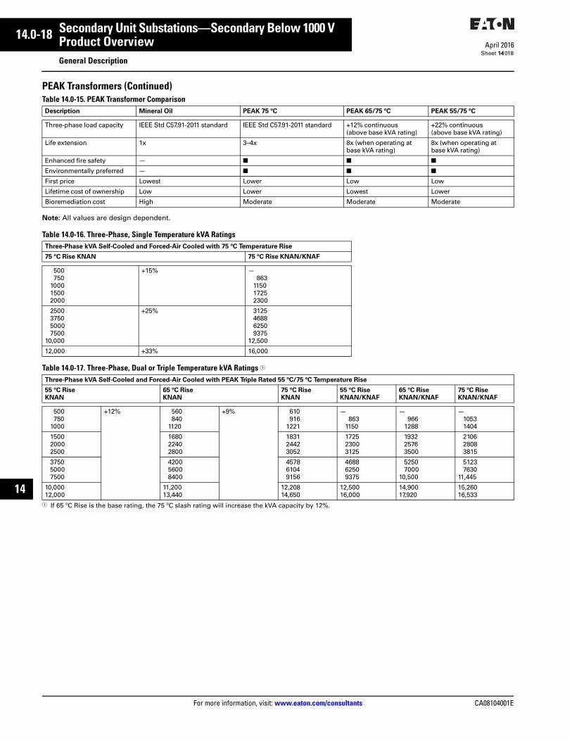
PEAK Transformers (Continued)Table 14.0-15. PEAK Transformer Comparison
Note: All values are design dependent.
Table 14.0-16. Three-Phase, Single Temperature kVA Ratings
Table 14.0-17. Three-Phase, Dual or Triple Temperature kVA Ratings 1
1 If 65 ºC Rise is the base rating, the 75 ºC slash rating will increase the kVA capacity by 12%.
Description Mineral Oil PEAK 75 ºC PEAK 65/75 ºC PEAK 55/75 ºC
Three-phase load capacity IEEE Std C57.91-2011 standard IEEE Std C57.91-2011 standard +12% continuous (above base kVA rating)
+22% continuous (above base kVA rating)
Life extension 1x 3–4x 8x (when operating at base kVA rating)
8x (when operating at base kVA rating)
Enhanced fire safety — ■ ■ ■
Environmentally preferred — ■ ■ ■
First price Lowest Lower Low Low
Lifetime cost of ownership Low Lower Lowest Lower
Bioremediation cost High Moderate Moderate Moderate
Three-Phase kVA Self-Cooled and Forced-Air Cooled with 75 ºC Temperature Rise
75 ºC Rise KNAN 75 ºC Rise KNAN/KNAF
500750
100015002000
+15% —863
115017252300
2500375050007500
10,000
+25% 3125468862509375
12,500
12,000 +33% 16,000
Three-Phase kVA Self-Cooled and Forced-Air Cooled with PEAK Triple Rated 55 ºC/75 ºC Temperature Rise
55 ºC Rise
KNAN
65 ºC Rise
KNAN
75 ºC Rise
KNAN
55 ºC Rise
KNAN/KNAF
65 ºC Rise
KNAN/KNAF
75 ºC Rise
KNAN/KNAF
500750
1000
+12% 560840
1120
+9% 610916
1221
—863
1150
—966
1288
—10531404
150020002500
168022402800
183124423052
172523003125
193225763500
210628083815
375050007500
420056008400
457861049156
468862509375
52507000
10,500
51237630
11,445
10,00012,000
11,20013,440
12,20814,650
12,50016,000
14,90017,920
15,26016,533
CA08104001E For more information, visit: www.eaton.com/consultants
14.0-19April 2016
Secondary Unit Substations—Secondary Below 1000 V
Sheet 14
i
ii
1
2
3
4
5
6
7
8
9
10
11
12
13
14
15
16
17
18
19
20
21
Product OverviewGeneral Description
019
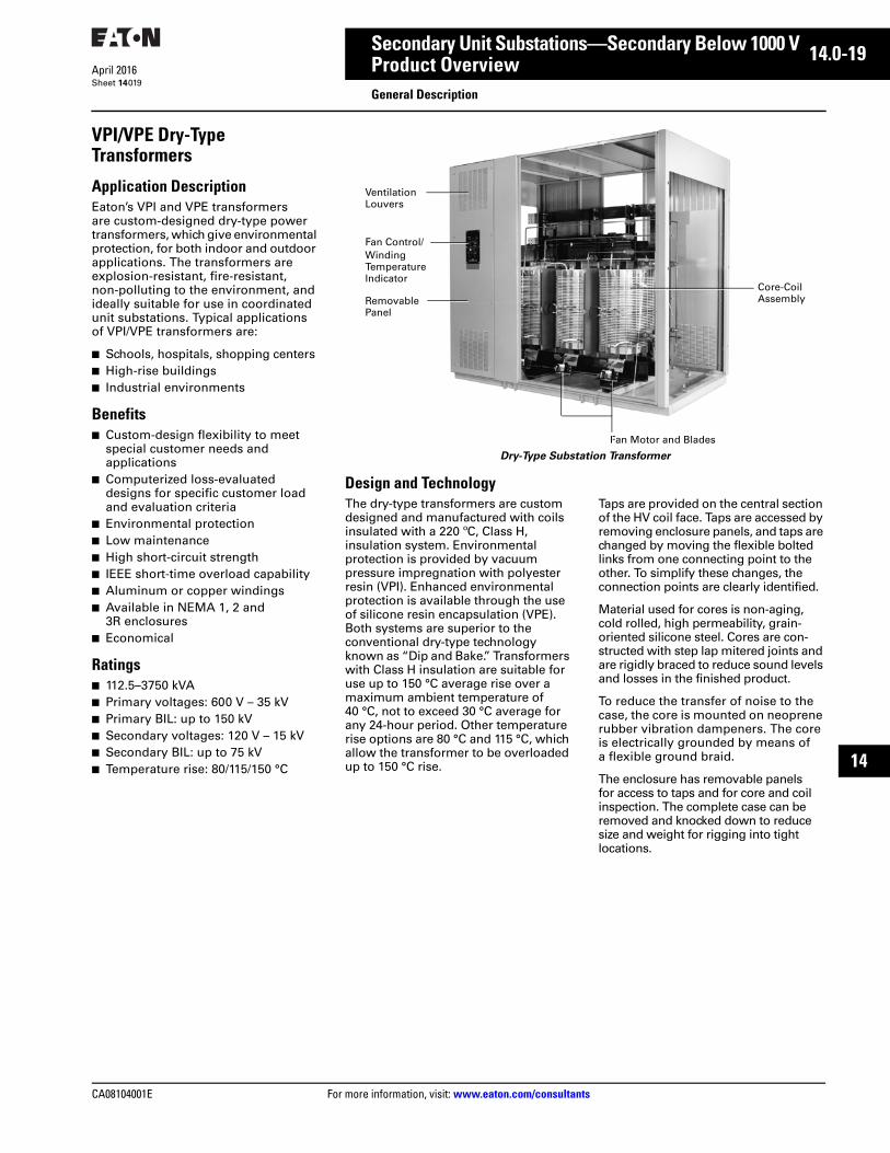
VPI/VPE Dry-Type Transformers
Application DescriptionEaton’s VPI and VPE transformers are custom-designed dry-type power transformers, which give environmental protection, for both indoor and outdoor applications. The transformers are explosion-resistant, fire-resistant, non-polluting to the environment, and ideally suitable for use in coordinated unit substations. Typical applications of VPI/VPE transformers are:
■ Schools, hospitals, shopping centers■ High-rise buildings■ Industrial environments
Benefits■ Custom-design flexibility to meet
special customer needs and applications
■ Computerized loss-evaluated designs for specific customer load and evaluation criteria
■ Environmental protection■ Low maintenance■ High short-circuit strength■ IEEE short-time overload capability■ Aluminum or copper windings■ Available in NEMA 1, 2 and
3R enclosures■ Economical
Ratings■ 112.5–3750 kVA■ Primary voltages: 600 V – 35 kV■ Primary BIL: up to 150 kV■ Secondary voltages: 120 V – 15 kV■ Secondary BIL: up to 75 kV■ Temperature rise: 80/115/150 °C
Dry-Type Substation Transformer
Design and TechnologyThe dry-type transformers are custom designed and manufactured with coils insulated with a 220 ºC, Class H, insulation system. Environmental protection is provided by vacuum pressure impregnation with polyester resin (VPI). Enhanced environmental protection is available through the use of silicone resin encapsulation (VPE). Both systems are superior to the conventional dry-type technology known as “Dip and Bake.” Transformers with Class H insulation are suitable for use up to 150 °C average rise over a maximum ambient temperature of 40 °C, not to exceed 30 °C average for any 24-hour period. Other temperature rise options are 80 °C and 115 °C, which allow the transformer to be overloaded up to 150 °C rise.
Taps are provided on the central section of the HV coil face. Taps are accessed by removing enclosure panels, and taps are changed by moving the flexible bolted links from one connecting point to the other. To simplify these changes, the connection points are clearly identified.
Material used for cores is non-aging, cold rolled, high permeability, grain-oriented silicone steel. Cores are con-structed with step lap mitered joints and are rigidly braced to reduce sound levels and losses in the finished product.
To reduce the transfer of noise to the case, the core is mounted on neoprene rubber vibration dampeners. The core is electrically grounded by means of a flexible ground braid.
The enclosure has removable panels for access to taps and for core and coil inspection. The complete case can be removed and knocked down to reduce size and weight for rigging into tight locations.
VentilationLouvers
Fan Control/Winding TemperatureIndicator
RemovablePanel
Fan Motor and Blades
Core-CoilAssembly

14.0-20
For more information, visit: www.eaton.com/consultants CA08104001E
April 2016
Secondary Unit Substations—Secondary Below 1000 V
Sheet 14
i
ii
1
2
3
4
5
6
7
8
9
10
11
12
13
14
15
16
17
18
19
20
21
Product OverviewGeneral Description
020
VPI/VPE Dry-Type Transformers (Continued)
AccessoriesStandard accessories include:
■ Jacking pads■ Ground pad■ Diagrammatic nameplate■ Provisions for rolling■ Ventilation grilles■ Core ground strap■ Primary reconnectable taps■ Future fan provisions on units
over 500 kVA■ ANSI 61 paint finish■ Step-lap mitered core■ NEMA 1 enclosure
Optional Features■ Copper windings/bussing
(aluminum is standard)■ VPE silicone resin vacuum pressure
impregnation and encapsulation■ Fan cooling package, complete with
digital winding temperature■ 80 °C or 115 °C rise (150 °C rise is
standard)■ Non-standard ambient temperature
(30 °C average/24-hour 40 °C maximum is standard)
■ Non-standard altitude (up to 3300 ft (1006 m) is standard)
■ Non-standard BIL level■ NEMA 3R enclosure■ Aluminum or copper ground bus■ Lightning arresters■ Low loss design (loss evaluation)■ Special sound level■ Wye-wye connected windings■ UL label
TestsThe following tests are standard:
■ Induced potential■ Applied potential■ Resistance measurement■ Ratio test■ Polarity and phase relationship test■ No load loss at rated voltage■ Exciting current at rated voltage■ Impedance and load loss■ Quality control impulse
Special TestsThe following tests can be provided at additional cost:
■ Temperature rise■ ANSI impulse■ Sound level■ Witness

CA08104001E For more information, visit: www.eaton.com/consultants
14.0-21April 2016
Secondary Unit Substations—Secondary Below 1000 V
Sheet 14
i
ii
1
2
3
4
5
6
7
8
9
10
11
12
13
14
15
16
17
18
19
20
21
Product OverviewGeneral Description
021
Cast Coil Transformers
Application DescriptionEaton’s cast coil transformers are premium, custom-designed, dry-type power transformers, which offer longer life, higher BIL levels, superior short-circuit strength and superior protection against high moisture, metallic dust-laden and harsh chemical environments. Cast coil transformers may be applied indoors as well as outdoors.
The transformers are explosion resistant, fire resistant, non-polluting to the environment and ideally suitable for use in coordinated unit substations. Typical applications of cast coil transformers are:
■ Steel mills■ High-rise buildings/rooftop units■ Pulp and paper mills■ Cement mills and mining operations■ Chemical plants■ Water-side installations, sand and
salt spray■ Onshore oil and gas
Benefits■ Practically maintenance free■ Highest possible short-circuit
strength■ Custom-design flexibility to meet
special customer needs and applications
■ Computerized loss-evaluated designs for specific customer load and evaluation criteria
■ Environmental immunity, unlimited storage
■ IEEE short-time overload capability■ Aluminum or copper windings■ Available in NEMA 1, 2 and
3R enclosures■ Ultimate impulse withstand■ Moisture and chemical resistant
Ratings■ 112.5–3750 kVA■ Primary voltage: 2300 V – 46 kV■ Primary BIL: up to 250 kV■ Secondary voltages: 120 V – 15 kV■ Secondary BIL: up to 95 kV■ Temperature rise: 80/100/115 °C
Cast Coil Substation Transformer
Design and TechnologyThe cast coil transformers are custom-designed and manufactured with coils insulated with materials such as glass mat and aramid fiber. The thickness of the epoxy is carefully engineeredto provide maximum strength and environmental protection and yet minimize the temperature differential through the core thickness in order to limit destructive stresses.
HV and LV coils are separately manufactured and mounted coaxially on the core legs with blocks to hold them firmly, yet permit expansion and contraction. HV windings are wound with one or more strands of rectangular wire, into disc or drum development, and placed into molds. They are dried and vacuum poured or cast, to eliminate moisture and voids in the sealing process. Low voltage windings are hermetically sealed in epoxy. Windings with operating voltage less than 600 V are cast using a pressure injection process. Winding with operating voltages greater than 600 V are processed using the same techniques employed for the high voltage windings. Although other low voltage techniques are available, this design offers the best long-term value in contaminated environments. Cast transformers use 185 °C class insulation and are typically specified for 80 °C average rise over a maximum ambient temperature of 40 °C, not to exceed 30 °C average for any 24-hour period. Other temperature rise options are 100 °C or 115 °C.
Taps are provided on the central section of the HV coil face. Taps are accessed by removing enclosure panels, and taps are changed by moving the flexible bolted links from one connecting point to the other. To simplify these changes, the connection points are clearly identified.
Material used for cores is non-aging, cold rolled, high permeability, grain-oriented silicone steel, cores are constructed with strap lap mitered joints and are rigidly braced to reduce sound levels and losses in the finished product.
To reduce the transfer of noise to the case, the core is mounted on neoprene rubber vibration dampeners. The core and associated core clamps and structural parts are electrically grounded to prevent an induced voltage buildup.
The enclosure has removable panels for access to taps, and for core and coil inspection. The complete case can be removed and knocked down to reduce size and weight for rigging into tight locations.
VentilationLouvers
Fan Control/Winding TemperatureIndicator
RemovablePanel
LV Bus
Core-CoilAssembly
HV Bus
Fan Motors and Blades
14.0-22
For more information, visit: www.eaton.com/consultants CA08104001E
April 2016
Secondary Unit Substations—Secondary Below 1000 V
Sheet 14
i
ii
1
2
3
4
5
6
7
8
9
10
11
12
13
14
15
16
17
18
19
20
21
Product OverviewGeneral Description
022
Cast Coil Transformers(Continued)
AccessoriesStandard accessories include:
■ Jacking pads■ Ground pad■ Diagrammatic nameplate■ Provisions for rolling■ Ventilation grilles■ Core ground strap■ Future fan provisions on units
over 500 kVA■ Reconnectable primary taps■ ANSI 61 paint finish■ Step-lap mitered core■ NEMA 1 enclosure
Optional Features■ Copper windings■ Full cast secondary■ Fan cooling package, complete with
digital winding temperature■ 100 °C or 115 °C rise (80 °C rise is
standard)■ Non-standard ambient temperature
(30 °C average/24-hour, 40 °C maximum is standard)
■ Non-standard altitude (up to 3300 ft (1006 m) is standard)
■ Non-standard BIL levels■ NEMA 3R enclosure■ Lightning arresters■ Low loss design (loss evaluation)■ Special sound level■ Wye-wye connected windings■ UL listing
TestsThe following tests are standard:
■ Induced potential■ Applied potential■ Resistance measurement■ Ratio test■ Polarity and phase relationship test■ No load loss■ Exciting current at rated voltage■ Impedance and load loss■ Partial discharge test (for coils rated
1.2 kV and higher)■ Quality control impulse
Special TestsThe following tests can be provided at additional cost:
■ Temperature rise■ ANSI impulse■ Sound level■ Witness
CA08104001E For more information, visit: www.eaton.com/consultants
14.0-23April 2016
Secondary Unit Substations—Secondary Below 1000 V
Sheet 14
i
ii
1
2
3
4
5
6
7
8
9
10
11
12
13
14
15
16
17
18
19
20
21
Product OverviewGeneral Description
023
RESIBLOC® Epoxy Cast Resin Transformers
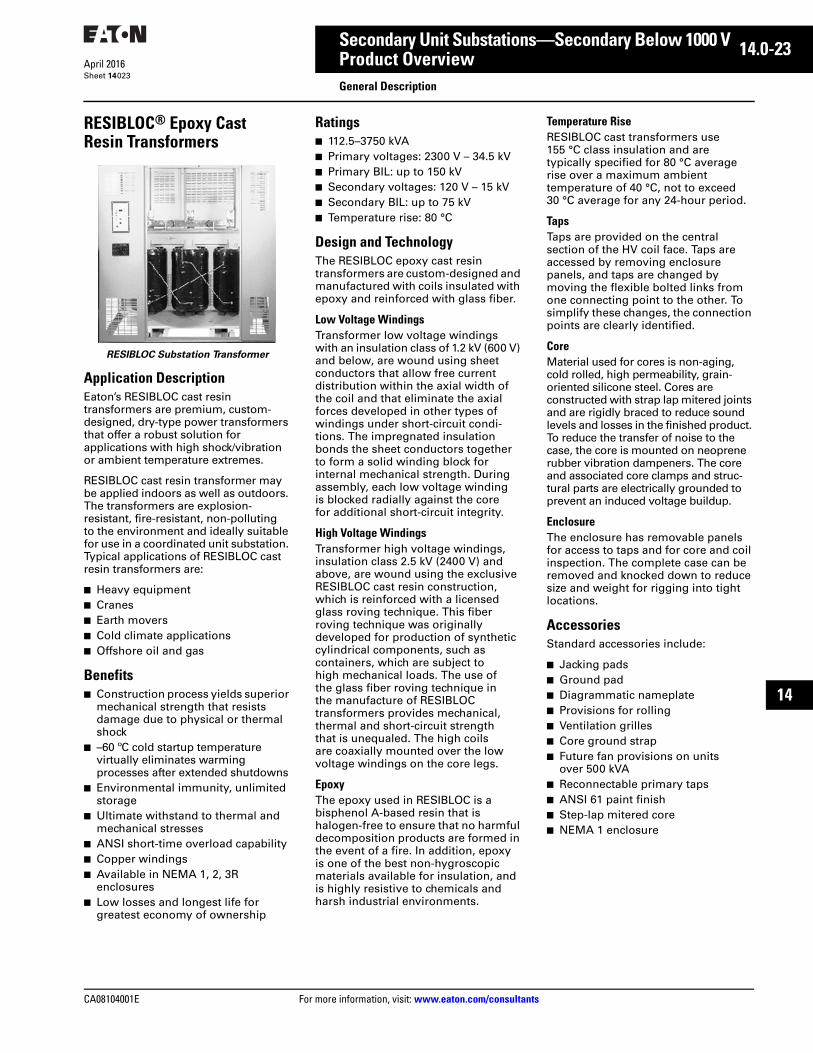
RESIBLOC Substation Transformer
Application DescriptionEaton’s RESIBLOC cast resin transformers are premium, custom-designed, dry-type power transformers that offer a robust solution for applications with high shock/vibration or ambient temperature extremes.
RESIBLOC cast resin transformer may be applied indoors as well as outdoors. The transformers are explosion-resistant, fire-resistant, non-polluting to the environment and ideally suitable for use in a coordinated unit substation. Typical applications of RESIBLOC cast resin transformers are:
■ Heavy equipment■ Cranes■ Earth movers■ Cold climate applications■ Offshore oil and gas
Benefits■ Construction process yields superior
mechanical strength that resists damage due to physical or thermal shock
■ –60 ºC cold startup temperature virtually eliminates warming processes after extended shutdowns
■ Environmental immunity, unlimited storage
■ Ultimate withstand to thermal and mechanical stresses
■ ANSI short-time overload capability■ Copper windings■ Available in NEMA 1, 2, 3R
enclosures■ Low losses and longest life for
greatest economy of ownership
Ratings■ 112.5–3750 kVA■ Primary voltages: 2300 V – 34.5 kV■ Primary BIL: up to 150 kV■ Secondary voltages: 120 V – 15 kV■ Secondary BIL: up to 75 kV■ Temperature rise: 80 °C
Design and TechnologyThe RESIBLOC epoxy cast resin transformers are custom-designed and manufactured with coils insulated with epoxy and reinforced with glass fiber.
Low Voltage WindingsTransformer low voltage windings with an insulation class of 1.2 kV (600 V) and below, are wound using sheet conductors that allow free current distribution within the axial width of the coil and that eliminate the axial forces developed in other types of windings under short-circuit condi-tions. The impregnated insulation bonds the sheet conductors together to form a solid winding block for internal mechanical strength. During assembly, each low voltage winding is blocked radially against the core for additional short-circuit integrity.
High Voltage WindingsTransformer high voltage windings, insulation class 2.5 kV (2400 V) and above, are wound using the exclusive RESIBLOC cast resin construction, which is reinforced with a licensed glass roving technique. This fiber roving technique was originally developed for production of synthetic cylindrical components, such as containers, which are subject to high mechanical loads. The use of the glass fiber roving technique in the manufacture of RESIBLOC transformers provides mechanical, thermal and short-circuit strength that is unequaled. The high coils are coaxially mounted over the low voltage windings on the core legs.
EpoxyThe epoxy used in RESIBLOC is a bisphenol A-based resin that is halogen-free to ensure that no harmful decomposition products are formed in the event of a fire. In addition, epoxy is one of the best non-hygroscopic materials available for insulation, and is highly resistive to chemicals and harsh industrial environments.
Temperature RiseRESIBLOC cast transformers use 155 °C class insulation and are typically specified for 80 °C average rise over a maximum ambient temperature of 40 °C, not to exceed 30 °C average for any 24-hour period.
TapsTaps are provided on the central section of the HV coil face. Taps are accessed by removing enclosure panels, and taps are changed by moving the flexible bolted links from one connecting point to the other. To simplify these changes, the connection points are clearly identified.
CoreMaterial used for cores is non-aging, cold rolled, high permeability, grain-oriented silicone steel. Cores are constructed with strap lap mitered joints and are rigidly braced to reduce sound levels and losses in the finished product. To reduce the transfer of noise to the case, the core is mounted on neoprene rubber vibration dampeners. The core and associated core clamps and struc-tural parts are electrically grounded to prevent an induced voltage buildup.
EnclosureThe enclosure has removable panels for access to taps and for core and coil inspection. The complete case can be removed and knocked down to reduce size and weight for rigging into tight locations.
AccessoriesStandard accessories include:
■ Jacking pads■ Ground pad■ Diagrammatic nameplate■ Provisions for rolling■ Ventilation grilles■ Core ground strap■ Future fan provisions on units
over 500 kVA■ Reconnectable primary taps■ ANSI 61 paint finish■ Step-lap mitered core■ NEMA 1 enclosure

14.0-24
For more information, visit: www.eaton.com/consultants CA08104001E
April 2016
Secondary Unit Substations—Secondary Below 1000 V
Sheet 14
i
ii
1
2
3
4
5
6
7
8
9
10
11
12
13
14
15
16
17
18
19
20
21
Product OverviewGeneral Description
024
RESIBLOC Epoxy Cast Resin Transformers (Continued)
Optional Features■ Fan cooling package, complete with
digital winding temperature■ Non-standard ambient temperature
(30 °C average/24-hour 40 °C maximum is standard)
■ Non-standard altitude (up to 3300 ft (1006 m) is standard)
■ Non-standard BIL level■ NEMA 3R enclosure■ Lightning arresters■ Low loss design (loss evaluation)■ Special sound level■ Wye-wye connected windings
TestsThe following tests are standard:
■ Induced potential■ Applied potential■ Resistance measurement■ Ratio test■ Polarity and phase relationship test.■ No load loss■ Exciting current at rated voltage■ Impedance and load loss■ Partial discharge test (for coils rated
1.2 kV and higher)■ Quality control impulse
Special TestsThe following tests can be provided at additional cost:
■ Temperature rise■ ANSI impulse■ Sound level■ Witness

CA08104001E For more information, visit: www.eaton.com/consultants
14.0-25April 2016
Secondary Unit Substations—Secondary Below 1000 V
Sheet 14
i
ii
1
2
3
4
5
6
7
8
9
10
11
12
13
14
15
16
17
18
19
20
21
Product OverviewGeneral Description
025
Magnum DS Low Voltage Metal-Enclosed Switchgear
Magnum DS Switchgear with Power Circuit Breaker
Product DescriptionEaton’s Magnum DS switchgear has a 50-year history of power circuit breaker and switchgear development that has set industry standards for quality, reliability, maintainability and extended operating life. Magnum DS switchgear is an assembled metal enclosure that houses drawout power circuit breakers and typically includes control and metering devices. Low voltage switchgear is applied at 600 V and less.
Application DescriptionSwitchgear is used for protection, control and monitoring of low voltage distribution systems in all types of industrial, commercial and utility environments requiring up to 600 V distribution between 1600 A and 10,000 A continuous loads, and between 42,000 A and 200,000 A interrupting current.
Product Offering■ Indoor NEMA 1■ Rear access■ Front access■ Arc resistant (2B)■ Integrated switchboard, MCC and ATS ■ Unit substation transformer integration■ Outdoor NEMA 3R rear access■ Outdoor NEMA 3R front access
Pow-R-Line C SwitchboardsSee Tab 21 for complete description and layout information.
Pow-R-Line C
Construction Details■ 6000 A main bus maximum■ Front and rear access—main section front and/or
side accessible■ Feeder devices panel mounted■ Sections rear aligned, or front and rear aligned■ Not designed for mounting against a wall, self-supporting
and requires code clearance at the rear
Main Devices—Individually Mounted■ Molded case circuit breaker, 400–2500 A, fixed or drawout■ Air power circuit breaker, Magnum DS, 800–6000 A, fixed
or drawout■ Air power circuit breaker with current limiting fuses, DSL,
800–5000 A■ Bolted pressure switch, 800–5000 A, fixed■ Fusible switches, 400–1200 A, fixed
Feeder Devices—Group Mounted■ Molded-case circuit breaker, 15–1200 A■ Fusible switches, 30–1200 A
Feeder Devices—Individually Mounted■ Air power circuit breaker, Magnum DS, 800–5000 A■ Bolted pressure switches, 800–5000 A, fixed■ Molded-case circuit breaker, 1600–2500 A

14.0-26
For more information, visit: www.eaton.com/consultants CA08104001E
April 2016
Secondary Unit Substations—Secondary Below 1000 V
Sheet 14
i
ii
1
2
3
4
5
6
7
8
9
10
11
12
13
14
15
16
17
18
19
20
21
Product OverviewGeneral Description
026
Secondary Unit Substation Plug-and-Play
General DescriptionFor years, Eaton has providedstandardized bus/cable coordination for unit substations, making it easier for installing contractors to put the substation components together inthe field. Now, Eaton is introducing the next evolution of substation coordination—new substation plug-and-play wiring.
Traditionally, installing contractors have relied on point-to-point wiring diagrams of each piece of equipment (medium voltage switch, transformer and low voltage switchgear) to do the substation control interconnects wiring. The new plug-and-play feature includes dedicated pull-apart terminal blocks and pre-made harnesses designed to eliminate the headaches associated with wiring control and communications devices inside a substation.
Features and Benefits
Features■ Pre-made wiring harness inside
the dry-type substation transformer, connecting the temperature controller, fans, low voltage switchgear and medium voltage switch components
■ Pull-apart terminal blocks between the medium voltage switch, transformer and low voltage switchgear for error proof installation
■ Basic feature set includes control power connections throughout the substation fed from the low voltage switchgear, as well as alarm/trip contacts from the transformer temperature controller
■ Includes RS-485 communications wiring throughout the substation if required
Benefits■ Reduces substation installation
time and complexity■ Reduces contractor-supplied
external wiring, including conduit, special communications wiring and terminal blocks
■ The interconnect points are pre-documented for easy reference
■ Communications wiring to devices throughout the substation (including medium voltage switch and transformer temperature controller) are connected back to the Power Xpert Gateway in the low voltage switchgear, for one network termination point in the substation
Figure 14.0-8. Plug-and-Play Diagram
MSB XFMR SWGR SECTION 1
13
1514
4567
98
1112
10
321
240/120VAC TO XFMR FROM LVA
PTS FROM MSB TO XPERT METER IN LVA
13
1514
4567
98
1112
10
TB6
321
13
1514
4567
98
1112
10
TB7
321
16
1817
13
1514
4567
98
1112
10
321
16
1817
120VAC CONTROL POWER FROM MSB TO XPERT METER IN LVA
PTS FROM MSB TO XPERT METER IN LVA
ALARM FROM XFMR TO MSB
TRIP FROM XFMR TO MSB
ALARM FROM XFMR TO MSB
TRIP FROM XFMR TO MSB
240/120VAC TO XFMR FROM LVA
LV 52 MAIN AUX bLV 52 MAIN AUX b
24VDC CONTROL 24VDC CONTROL
MV 52 AUX bMV 52 AUX b
(3) CTS MOUNTED IN LVA TO ETR-4000ETR-4000
(3) CTS MOUNTED IN LVA TO DT 520MVDT 520MV
PXM-MV(3) CTS MOUNTED IN MSB TO PXM-MV
CT WIRING TO RUN DIRECT BETWEEN MSB AND SWGR. NO TERMINAL BLOCKS IN XFMR.
NCBA
F1
F2Y
+-
NCBA
LN+-
TB7 TB6
16
1817 RS-485 MODBUS TO PXG600A
16
1817RS-485 MOSBUS FROM TEMP CONTROLLER
A
SH/COMB
19
2120
22
2423
19
2120
22
2423
19
2120
22
2423
19
2120
22
2423
MV 52 REMOTE CLOSE
MV 52 REMOTE OPEN
MV 52 REMOTE CLOSE
MV 52 REMOTE OPEN
ETR4000 TRIPETR4000 TRIP
MVV1
MVV2MVV3MVV4
24+24-531053113CB18
3CB19
B2CGB2C1B2C2B2C3
B1C1B1G1B1C2B1G2B1C3B1G3
MVCGMVC1MVC2MVC3
STBB2
STBB1
TB619
TB620
TB621TB622TB623TB624
SPARE

CA08104001E For more information, visit: www.eaton.com/consultants
14.0-27April 2016
Secondary Unit Substations—Secondary Below 1000 V
Sheet 14
i
ii
1
2
3
4
5
6
7
8
9
10
11
12
13
14
15
16
17
18
19
20
21
Product OverviewGeneral Description
027
TC-100 Transformer Temperature Controller for Dry-Type Transformers
TC-100
General DescriptionThe TC-100 Transformer Temperature Controller monitors up to three venti-lated dry-type transformer windings and one ambient temperature. The TC-100 operates relays by comparing the highest winding temperature to stored set point temperatures and displays four thermocouple inputs, as well as the stored maximum temperature and its associated wind-ing. The unit provides fans, alarm and trip output relays. Up to two fans can be controlled via the TC-100. Each fan operating contact is fuse protected.A yellow LED indicates that fans are on. A fan exerciser turns the fans on automatically at periodic intervals to prevent fan motor seizing (on-time and interval is programmable).
Form C contacts are provided for notification of alarm conditions. A red LED illuminates to indicate that the alarm is actuated. An internal audible alarm also sounds when the unit goes into alarm condition. This audible buzzer can be silenced without cancel-ing the alarm. The alarm and trip relays can be configured as a fail-safe relay (normally energized when the unit is powered up). For example, if the alarm relay was configured as a fail-safe; if supply control power to the TC-100 is interrupted, the alarm relay changes state for notification of this condition. The alarm circuit is also used for notification of an open or a missing thermocouple. If a thermocouple were to open, the alarm relay operates and the corresponding channel will read “-” on the LED display. It is important to note that a failed thermocouple will not cause the device to trip the transformer offline.
Form C contacts are provided to trip the transformer offline if any of the winding temperatures exceed the trip setting. A red LED indicates that the trip relay has actuated.
A test function is provided to: test the digital display and all of the LEDs; simulate over-temperature conditions; and check the internal temperature of the monitor.
A 4–20 mA analog signal is provided for remote indication or for use with SCADA systems.
The TC-100 has built-in monitoring functions and logging functions to help you shed some light on the unknowns of the operation of your transformer. Temperature trending lets you understand the hour of the day that the transformer runs hotter, and modify its loading to extend the life of your transformer; logging information lets you restore the operation of your system faster, by letting you correlate tripping and alarming events to the overall conditions of your system; and fan wear information can be used to perform preventive mainte-nance to increase the uptime in your transformers.
Features and Benefits
Control■ Thermocouple inputs (E or K type
thermocouples)■ Automatic correlation throughout
entire temperature range to compensate for thermocouple non-linearity
■ Programmable on and off set points■ Alarm relay for remote monitoring■ Trip relay for remote monitoring■ Two fan power relays■ Fan failure detection to start a
backup fan or alarm■ Fan exerciser (cycle time and
duration) to reduce fan wear■ Fans can be operated automatically
or manually
Metering■ Average temperature
(all three windings)■ Maximum instantaneous
temperature (all three windings)■ Maximum temperature memory
per winding■ Fans hours of operation■ Winding 1, Winding 2, Winding 3
and ambient temperature
Monitoring■ Trending■ Fan failure■ Fan wear■ Alarm log■ Trip log■ Test mode■ Detect failed sensors■ Self-diagnostics
Communications■ USB port in the front■ Modbus-RTU communications■ Programming and monitoring
software (the unit can be completely programmed through the front of the unit)
■ 4–20 mA output for integration with SCADA systems
Hardware■ One trip relay (Form C)■ One alarm relay (Form C)■ Two power fan relays (1 NO each)■ Two digital inputs■ 4–20 mA output for integration with
SCADA systems■ Local Alarm 95 db■ Available in semi-flush or hinge
panel-mounting versions

14.0-28
For more information, visit: www.eaton.com/consultants CA08104001E
April 2016
Secondary Unit Substations—Secondary Below 1000 V
Sheet 14
i
ii
1
2
3
4
5
6
7
8
9
10
11
12
13
14
15
16
17
18
19
20
21
Layout DimensionsIndoor Liquid-Filled
028
Indoor Composite Floor Plan—Liquid-Filled Transformer
Figure 14.0-9. Liquid-Filled, Indoor—Top View
1 For three-phase, four-wire, D1F is 30.25.2 Contact Eaton.
Table 14.0-19. Secondary Equipment Dimension References—Dimensions in Inches (mm)
Table 14.0-18. Primary Equipment Dimension References Legend:MVC = Medium Voltage Motor Control,
Type AMPGARDMVS = Medium Voltage Metal-Enclosed
Switches, Type MVSME = Medium Voltage Metal-Enclosed
Breakers, Type MEB, MEF, MSBMC = Medium Voltage Metal-Clad Breaker
Assemblies, Type VacClad-W
Primary
Equipment
Dimensions Reference
Page(s)
TransformerMVSMEMC
WTX, DTXWP, DPWP, DPWP, DP
Page 14.0-35
Page 14.0-34
Page 14.0-34
Tab 5
Air Terminal Chamber (ATC) or Transition Section—Dimensions in Inches (mm)Voltage
kV
Primary
Equipment
Three-Phase, Three-Wire or Three-Phase Four-Wire
W1 D1F
5 or 15 MVSMEMC
20.00 (508.0)20.00 (508.0)18.00 (457.2)
25.25 (641.3) 125.25 (641.3) 142.50 (1079.5)
27 MVSMC
30.00 (762.0)36.00 (914.4)
2
2
38 MVSMC
30.00 (762.0)42.00 (1066.8)
2
2
Secondary Equipment
Rear
Primary Equipment Transformer
of Transformer
TransitionSection
TransitionSection
CL DS
WS
DTX
WTXWP W1
DP
Front
D1F
W2
D2R
D2F
Secondary
Equipment
W2 D2F D2R For WS, DS Dimensions
Tab-Page
Magnum DS and SB switchgear (rear access) 22.00 (558.8) 45.00 (1143.0) — 20.1
Pow-R-Line C switchboard (front access)Pow-R-Line C switchboard (rear access)Pow-R-Line i switchboard (rear access)
20.00 (508.0)20.00 (508.0)20.00 (508.0)
———
24.00 (609.6)24.00 (609.6)24.00 (609.6)
21.1 (All)
21.2 (All)
21.3 (All)
Dimensions for estimating purposes only.

CA08104001E For more information, visit: www.eaton.com/consultants
14.0-29April 2016
Secondary Unit Substations—Secondary Below 1000 V
Sheet 14
i
ii
1
2
3
4
5
6
7
8
9
10
11
12
13
14
15
16
17
18
19
20
21
Layout DimensionsOutdoor Liquid-Filled
029
Outdoor Composite Floor Plan—Liquid-Filled Transformer
Figure 14.0-10. Liquid-Filled, Outdoor Enclosure—Top View1 Radiator position and number of radiators will vary based on design.
2 For three-phase, four-wire, D1F is 30.25 inches (768.4 mm).3 For three-phase, four-wire, D1R is 14.50 inches (368.3 mm).4 Contact Eaton.
Table 14.0-21. Secondary Equipment Dimension References—Dimensions in Inches (mm)
Table 14.0-20. Primary Equipment Dimension References Legend:MVC = Medium Voltage Motor Control,
Type AMPGARDMVS = Medium Voltage Metal-Enclosed
Switches, Type MVSME = Medium Voltage Metal-Enclosed
Breakers, Type MEB, MSBMC = Medium Voltage Metal-Clad Breaker
Assemblies, Type VacClad-W
Primary Equipment
Dimensions Reference Page(s)
TransformerMVSMEMC
WTX, DTXWP, DPWP, DPWP, DP
Page 14.0-35
Page 14.0-34
Page 14.0-34
Tab 5
Air Terminal Chamber (ATC) or Transition Section/Throat—Dimensions in Inches (mm)VoltagekV
Primary Equipment
Three-Phase, Three-Wire or Three-Phase Four-Wire
W1 D1F D1R
5 or 15 MVSMEMC
20.00 (508.0)20.00 (508.0)16.00 (406.4)
25.25 (641.3) 225.25 (641.3) 2—
——16.50 (419.1) 3
27 MVSMC 4
35.00 (889.0)—
——
——
38 MVSMC 4
35.00 (889.0)—
——
——
Secondary
Equipment
W2 D2R For WS, DS Dimensions
Tab-Page
Magnum DS and SB switchgear 38.50 (977.9) 27.00 (685.8) 20.1
Pow-R-Line C switchboard (front access)Pow-R-Line C switchboard (rear access)Pow-R-Line i switchboard (rear access)
25.00 (635.0)25.00 (635.0)25.00 (635.0)
20.00 (508.0)20.00 (508.0)25.00 (635.0)
21.1 (All)
21.2 (All)
21.3 (All)
Dimensions for estimating purposes only.
Secondary EquipmentP
rim
ary
Eq
uip
men
t
Transformer
Tra
nsi
tio
n S
ecti
on
/Th
roat
CL
DS
WS
DTX
W TXWP W1
DP
D1F
D1R
¿
of Transformer
Tra
nsi
tio
nS
ecti
on
/Th
roat
W2
DoorSwing
D2R
Walk-in Aisle (if used)
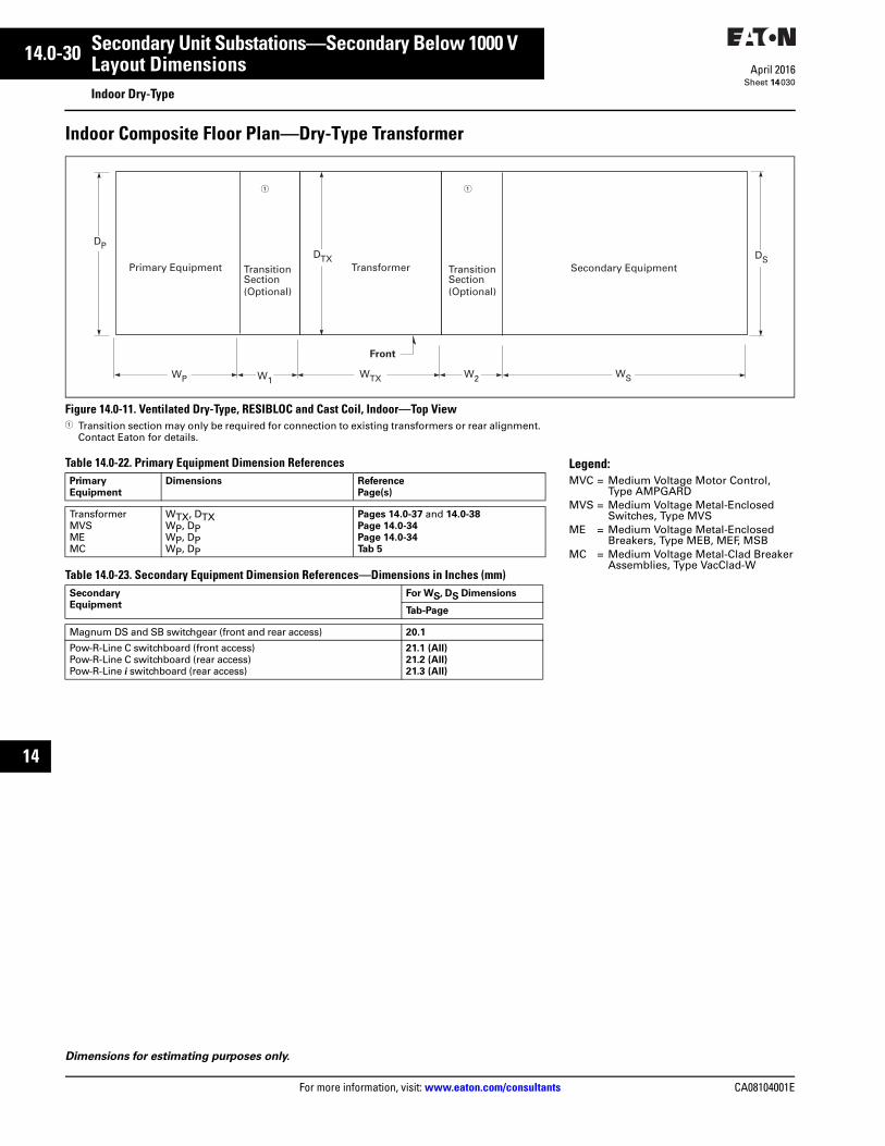
14.0-30
For more information, visit: www.eaton.com/consultants CA08104001E
April 2016
Secondary Unit Substations—Secondary Below 1000 V
Sheet 14
i
ii
1
2
3
4
5
6
7
8
9
10
11
12
13
14
15
16
17
18
19
20
21
Layout DimensionsIndoor Dry-Type
030
Indoor Composite Floor Plan—Dry-Type Transformer
Figure 14.0-11. Ventilated Dry-Type, RESIBLOC and Cast Coil, Indoor—Top View 1 Transition section may only be required for connection to existing transformers or rear alignment.
Contact Eaton for details.
Table 14.0-22. Primary Equipment Dimension References
Table 14.0-23. Secondary Equipment Dimension References—Dimensions in Inches (mm)
Dimensions for estimating purposes only.
Primary
Equipment
Dimensions Reference
Page(s)
TransformerMVSMEMC
WTX, DTXWP, DPWP, DPWP, DP
Pages 14.0-37 and 14.0-38
Page 14.0-34
Page 14.0-34
Tab 5
Secondary
Equipment
For WS, DS Dimensions
Tab-Page
Magnum DS and SB switchgear (front and rear access) 20.1
Pow-R-Line C switchboard (front access)Pow-R-Line C switchboard (rear access)Pow-R-Line i switchboard (rear access)
21.1 (All)
21.2 (All)
21.3 (All)
Secondary EquipmentPrimary Equipment TransformerTransitionSection(Optional)
TransitionSection(Optional)
DS
WS
DTX
WTXWP W1
DP
Front
W2
1 1
Legend:MVC = Medium Voltage Motor Control,
Type AMPGARDMVS = Medium Voltage Metal-Enclosed
Switches, Type MVSME = Medium Voltage Metal-Enclosed
Breakers, Type MEB, MEF, MSBMC = Medium Voltage Metal-Clad Breaker
Assemblies, Type VacClad-W

CA08104001E For more information, visit: www.eaton.com/consultants
14.0-31April 2016
Secondary Unit Substations—Secondary Below 1000 V
Sheet 14
i
ii
1
2
3
4
5
6
7
8
9
10
11
12
13
14
15
16
17
18
19
20
21
Layout DimensionsOutdoor Dry-Type
031
Outdoor Composite Floor Plan—Dry-Type Transformer
Figure 14.0-12. Ventilated Dry-Type, RESIBLOC and Cast Coil, Outdoor—Top View1 Transition section may only be required for connection to existing transformers or rear alignment. Contact Eaton for details.
1 Contact Eaton.
Table 14.0-25. Secondary Equipment Dimension References—Dimensions in Inches (mm)
Table 14.0-24. Primary Equipment Dimension References Legend:MVC = Medium Voltage Motor Control,
Type AMPGARDMVS = Medium Voltage Metal-Enclosed
Switches, Type MVSME = Medium Voltage Metal-Enclosed
Breakers, Type MEB, MSBMC = Medium Voltage Metal-Clad Breaker
Assemblies, Type VacClad-W
Primary
Equipment
Dimensions Reference
Page(s)
TransformerMVSMEMC
WTX, DTXWP, DPWP, DPWP, DP
Pages 14.0-37 and 14.0-38
Page 14.0-34
Page 14.0-34
Tab 5
Air Terminal Chamber (ATC) or Transition Section/Throat—Dimensions in Inches (mm)Primary
Equipment
W1
5 kV 15 kV 27 kV 38 kV
MVSMEMC
5.00 (127.0)5.00 (127.0)
16.00 (406.4)
5.00 (127.0)5.00 (127.0)
16.00 (406.4)
1
N/A1
1
N/A1
Secondary Equipment
Pri
mar
y E
qu
ipm
ent
Transformer
Tra
nsi
tio
n S
ecti
on
(O
pti
on
al)
Tra
nsi
tio
n S
ecti
on
(O
pti
on
al)
DS
WS
DTX
WTXWP W1
DP
Front
W2
1 1
Secondary
Equipment
W2 For WS, DS Dimensions
Tab-Page
Magnum DS and SB switchgear 38.50 (977.9) 20.1
Pow-R-Line C switchboard (front access)Pow-R-Line C switchboard (rear access)Pow-R-Line i switchboard (rear access)
5.00 (127.0)5.00 (127.0)5.00 (127.0)
21.1 (All)
21.2 (All)
21.3 (All)
Dimensions for estimating purposes only.

14.0-32
For more information, visit: www.eaton.com/consultants CA08104001E
April 2016
Secondary Unit Substations—Secondary Below 1000 V
Sheet 14
i
ii
1
2
3
4
5
6
7
8
9
10
11
12
13
14
15
16
17
18
19
20
21
Layout DimensionsSubstation with Air Terminal Chamber (ATC)
032
Substation with Air Terminal Chamber (ATC) Usage—Liquid-Filled TransformerA substation using one or two air terminal chambers (ATCs) is different from a substation using close-coupling on both the primary and secondary sides. An ATC uses a cable connection on either the primary side, secondary side or both, and is placed between the transformer and the remotely mounted primary or secondary equipment.
Figure 14.0-13. Liquid-Filled Indoor/Outdoor Using Air Terminal Chambers—Top View1 Radiator position and number of radiators will vary based on design.
Table 14.0-26. Primary ATC or Transition Section—Dimensions in Inches (mm)
Note: Minimum ATC widths by kVA are listed in the table above. The width of any ATC can be expanded to allow for the installation of additional conduits. When calculating the area of the conduit opening, allow for a 2.00-inch (50.8 mm) lip around the entire perimeter of the ATC.
Table 14.0-27. Secondary ATC or Transition Section—Dimensions in Inches (mm)
Note: Minimum ATC widths by kVA are listed in the table above. The width of any ATC can be expanded to allow for the installation of additional conduits. When calculating the area of the conduit opening, allow for a 2.00-inch (50.8 mm) lip around the entire perimeter of the ATC.
Transformer
Air
Ter
min
al C
ham
ber
CL
DSDTX
W TXW1
DP
D1F
D1R
�
of Transformer
Air
Ter
min
al C
ham
ber
W2
D2R
Voltage Three-Phase, Three-Wire or Three-Phase, Four-Wire
kV W1 DP
5 or 152738
18.00 (457.2)24.00 (609.6)36.00 (914.4)
DTXDTXDTX
Voltage W2 DS
V
All 18.00 (457.2) DTX
Dimensions for estimating purposes only.
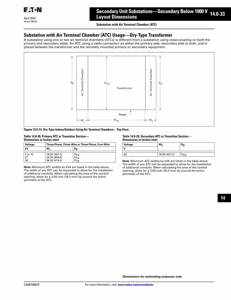
CA08104001E For more information, visit: www.eaton.com/consultants
14.0-33April 2016
Secondary Unit Substations—Secondary Below 1000 V
Sheet 14
i
ii
1
2
3
4
5
6
7
8
9
10
11
12
13
14
15
16
17
18
19
20
21
Layout DimensionsSubstation with Air Terminal Chamber (ATC)
033
Substation with Air Terminal Chamber (ATC) Usage—Dry-Type TransformerA substation using one or two air terminal chambers (ATCs) is different from a substation using close-coupling on both the primary and secondary sides. An ATC using a cable connection on either the primary side, secondary side or both, and is placed between the transformer and the remotely mounted primary or secondary equipment.
Figure 14.0-14. Dry-Type Indoor/Outdoor Using Air Terminal Chambers—Top View
Table 14.0-28. Primary ATC or Transition Section—Dimensions in Inches (mm)
Note: Minimum ATC widths by kVA are listed in the table above. The width of any ATC can be expanded to allow for the installation of additional conduits. When calculating the area of the conduit opening, allow for a 3.00-inch (76.2 mm) lip around the entire perimeter of the ATC.
Table 14.0-29. Secondary ATC or Transition Section—Dimensions in Inches (mm)
Note: Minimum ATC widths by kVA are listed in the table above. The width of any ATC can be expanded to allow for the installation of additional conduits. When calculating the area of the conduit opening, allow for a 3.00-inch (76.2 mm) lip around the entire perimeter of the ATC.
Transformer
Air
Ter
min
al C
ham
ber
Air
Ter
min
al C
ham
ber
DSDTX
WTXW1
DP
Front
W2
Voltage Three-Phase, Three-Wire or Three-Phase, Four-Wire
kV W1 DP
5 or 152738
18.00 (457.2)24.00 (609.6)36.00 (914.4)
DTXDTXDTX
Voltage W2 DS
V
All 18.00 (457.2) DTX
Dimensions for estimating purposes only.

14.0-34
For more information, visit: www.eaton.com/consultants CA08104001E
April 2016
Secondary Unit Substations—Secondary Below 1000 V
Sheet 14
i
ii
1
2
3
4
5
6
7
8
9
10
11
12
13
14
15
16
17
18
19
20
21
Layout DimensionsPrimary Switching Equipment
034
Primary Switching Equipment—Type MVS/MSB Switchgear
Figure 14.0-15. Primary Equipment Floor Plan
Table 14.0-30. Primary Switching Equipment—Type MVS Switchgear
1 A transition section is required when any MVS switchgear assembly is connected to a liquid-filled transformer and when any MSB switchgear assembly is connected to any kind of transformer. When a 5 or 15 kV MVS switchgear assembly is connected to a dry-type or cast coil transformer, no transition section is required when installed indoors, but a 5.00-inch (127.0 mm) throat is required when installed outdoors.
2 Where disconnect fuses are used, add 6.00 inches (152.4 mm) to section width, 5 and 15 kV only.3 When height of 101.50 inches (2578.1 mm) is used with fuses identified in footnote 4, the depth increases to 100.00 inches (2540.0 mm).4 Height is 101.50 inches (2578.1 mm) for 27 kV MVS switchgear without fuses or with Cooper type NX fuses, and 38 kV MVS switchgear without
fuses or with GE type EJO-1 fuses.5 Height is 110.00 inches (2794.0 mm) for 27 kV MVS switchgear without fuses or with Cooper type NX fuses, and 38 kV MVS switchgear without
fuses or with GE type EJO-1 fuses.6 Can be 62.00 inches (1574.8 mm) deep if incoming cable enters from below.
Table 14.0-31. Primary Switching Equipment—Type MSB Switchgear
7 A transition section is required when any MVS switchgear assembly is connected to a liquid-filled transformer and when any MSB switchgear assembly is connected to any kind of transformer. When a 5 or 15 kV MVS switchgear assembly is connected to a dry-type or cast coil transformer, no transition section is required when installed indoors, but a 5.00-inch (127.0 mm) throat is required when installed outdoors.
Configuration of Switch(es)
RatedMaximumVoltage, kV
FaultClose kVAsym.Maximum
Dimensions in Inches (mm)
WP 12 DP Height(Indoor)
Height (OutdoorNon-Walk-in)
WC CC
Three-Wire Four-Wire
Single switch
5152738
64646030
36.00 (914.4) 36.00 (914.4) 48.00 (1219.2) 48.00 (1219.2)
55.30 (1404.6)55.30 (1404.6)80.00 (2032.0)80.00 (2032.0)
62.00 (1574.8)62.00 (1574.8)80.00 (2032.0) 380.00 (2032.0) 3
90.40 (2296.2)90.40 (2296.2)
127.00 (3225.8) 4127.00 (3225.8) 4
95.50 (2425.7)95.50 (2425.7)
135.00 (3429.0) 5135.00 (3429.0) 5
10.00 (254.0)10.00 (254.0)16.00 (406.4)16.00 (406.4)
8.00 (203.2)8.00 (203.2)8.00 (203.2)8.00 (203.2)
Duplex (two)switches
5152738
64646030
72.00 (1828.8) 72.00 (1828.8) 96.00 (2438.4) 96.00 (2438.4)
62.00 (1574.8)62.00 (1574.8)
100.00 (2540.0)100.00 (2540.0)
62.00 (1574.8)62.00 (1574.8)
100.00 (2540.0)100.00 (2540.0)
90.40 (2296.2)90.40 (2296.2)
127.00 (3225.8) 4127.00 (3225.8) 4
95.50 (2425.7)95.50 (2425.7)
135.00 (3429.0) 5135.00 (3429.0) 5
10.00 (254.0)10.00 (254.0)16.00 (406.4)16.00 (406.4)
8.00 (203.2)8.00 (203.2)8.00 (203.2)8.00 (203.2)
Selector switch
515
6464
36.00 (914.4) 36.00 (914.4)
62.00 (1574.8)70.00 (1778.0) 6
62.00 (1574.8)70.00 (1778.0) 6
90.40 (2296.2)90.40 (2296.2)
95.50 (2425.7)95.50 (2425.7)
10.00 (254.0)10.00 (254.0)
20.00 (508.0)20.00 (508.0)
Sectional-izingloop feed switches
5152738
64646030
108.00 (2743.2)108.00 (2743.2)144.00 (3657.6)144.00 (3657.6)
55.30 (1404.6)55.30 (1404.6)80.00 (2032.0) 380.00 (2032.0) 3
62.00 (1574.8)62.00 (1574.8)80.00 (2032.0) 380.00 (2032.0) 3
90.40 (2296.2)90.40 (2296.2)
127.00 (3225.8) 4127.00 (3225.8) 4
95.50 (2425.7)95.50 (2425.7)
135.00 (3429.0) 5135.00 (3429.0) 5
10.00 (254.0)10.00 (254.0)16.00 (406.4)16.00 (406.4)
8.00 (203.2)8.00 (203.2)8.00 (203.2)8.00 (203.2)
Configurationof Switch(es)and Vacuum Breaker
RatedMaximumVoltage, kV
Fault ClosekV Asym.Maximum
Dimensions in Inches (mm)
WP 7 DP Height(Indoor)
Height (OutdoorNon-Walk-in)
WC CC
Single 515
6464
42.00 (1066.8)42.00 (1066.8)
70.00 (1778.0)70.00 (1778.0)
90.40 (2296.2)90.40 (2296.2)
95.50 (2425.7)95.50 (2425.7)
10.00 (254.0)10.00 (254.0)
8.00 (203.2)8.00 (203.2)
Duplex 515
6464
78.00 (1981.2)78.00 (1981.2)
70.00 (1778.0)70.00 (1778.0)
90.40 (2296.2)90.40 (2296.2)
95.50 (2425.7)95.50 (2425.7)
10.00 (254.0)10.00 (254.0)
8.00 (203.2)8.00 (203.2)
Sectionalizingloop feed switches
515
6464
114.00 (2895.6)114.00 (2895.6)
70.00 (1778.0)70.00 (1778.0)
90.40 (2296.2)90.40 (2296.2)
95.50 (2425.7)95.50 (2425.7)
10.00 (254.0)10.00 (254.0)
8.00 (203.2)8.00 (203.2)
l
52
l
52
52
Single or SelectorPlan View
Duplex Plan View
Sectionalized Loop FeedPlan View
6.6 (167.6)
WP WP WP
CC
WC WC
CC
WC WC WC WC
CC
WC WC WC WC
D P
6.6 (167.6)6.6
(167.6)
Table 14.0-32. Approximate Weights in Lb (kg)
Dimensions for estimating purposes only.
Description Indoor Outdoor
5 or 15 kV Class
MSB sectionMVS section (non-fused)
Fuses (3) addTransition sectionOutdoor throat
1600 (726)1500 (681)
200 (91)300 (136)
—
1900 (863)1800 (817)
200 (91)—1200 (544)
25.8 or 38 kV Class
MVS section (non-fused)
Fuses (3) addTransition sectionOutdoor throat
2000 (908)
300 (136)1100 (499)—
2400 (1090)
300 (136)—1200 (544)

CA08104001E For more information, visit: www.eaton.com/consultants
14.0-35April 2016
Secondary Unit Substations—Secondary Below 1000 V
Sheet 14
i
ii
1
2
3
4
5
6
7
8
9
10
11
12
13
14
15
16
17
18
19
20
21
Layout DimensionsTransformers
035
Liquid-Filled TransformersTable 14.0-33. Oil-Filled Standard Design, 60 Hz, HV Delta, LV at 600 V Class (30 kV BIL) Indoor or Outdoor Application
Figure 14.0-16. Liquid-Filled, Indoor and Outdoor1 = 55.00 inches (1397.0 mm) for all ratings through 15 kV primary,
600 V secondary.
kVA HV, kV HV BIL, kV Dimensions in Inches (mm) Weight
Lb (kg)
Liquid
Gallons (Liters)HTX WTX DTX
Oil-Filled 55°, 65° and 75 °C Rise300 5 or 15 60 or 95 74.05 (1880.9) 65.50 (1663.7) 53.50 (1358.9) 4800 (2177) 330 (1249)
500 5 or 15 60 or 95 74.05 (1880.9) 67.50 (1714.5) 57.50 (1460.5) 5800 (2631) 330 (1249)
750 5 or 1525 or 35
60 or 95125 or 150
74.05 (1880.9)74.05 (1880.9)
71.50 (1816.1)78.00 (1981.2)
59.50 (1511.3)66.50 (1689.1)
6800 (3084)8500 (3856)
370 (1401) 460 (1741)
1000 5 or 1525 or 35
60 or 95125 or 150
82.05 (2084.1)82.05 (2084.1)
75.50 (1917.7)82.00 (2082.8)
59.50 (1511.3)66.50 (1689.1)
8400 (3810)9400 (4264)
440 (1666)480 (1817)
1500 5 or 1525 or 35
60 or 95125 or 150
82.05 (2084.1)82.05 (2084.1)
79.10 (2009.1)91.60 (2326.6)
84.70 (2151.4)91.70 (2329.2)
10,800 (4899)12500 (5670)
480 (1817)600 (2271)
2000 5 or 1525 or 35
60 or 95125 or 150
82.05 (2084.1)82.05 (2084.1)
81.10 (2060.0)93.60 (2377.4)
94.10 (2390.1)97.10 (2466.3)
13,000 (5897)15,000 (6804)
500 (1893)620 (2347)
2500 5 or 1525 or 35
60 or 95125 or 150
82.05 (2084.1)82.05 (2084.1)
89.10 (2263.1)103.60 (2631.4)
94.10 (2390.1)98.10 (2491.7)
15,500 (7031)18,800 (8528)
560 (2120)730 (2763)
3000 25 or 35 125 or 150 92.25 (2343.2) 89.60 (2275.8) 119.90 (3045.5) 19,000 (8618) 750 (2839)
3750 25 or 35 125 or 150 106.50 (2705.1) 97.60 (2479.0) 119.90 (3045.5) 23,000 (10,433) 980 (3710)
5000 5 or 15 60 or 95 85.00 (2159.0) 98.00 (2489.2) 105.00 (2667.0) 25,000 (11,340) 960 (3634)
Plan Elevation
HTX
WTX
¿
DTX CL
of BushingCL
Dimensions for estimating purposes only.
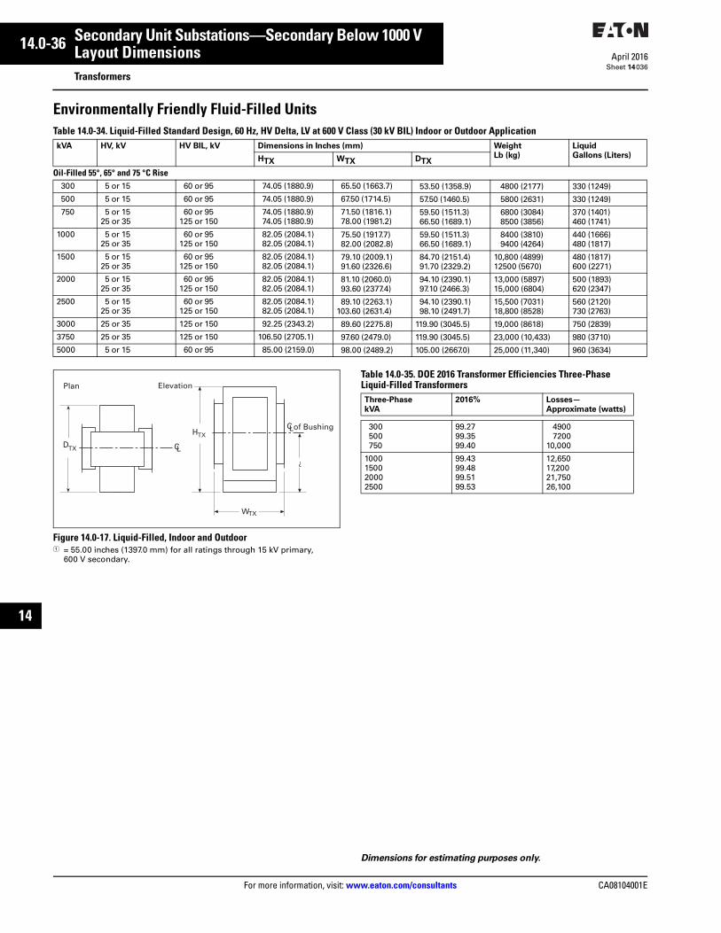
14.0-36
For more information, visit: www.eaton.com/consultants CA08104001E
April 2016
Secondary Unit Substations—Secondary Below 1000 V
Sheet 14
i
ii
1
2
3
4
5
6
7
8
9
10
11
12
13
14
15
16
17
18
19
20
21
Layout DimensionsTransformers
036
Environmentally Friendly Fluid-Filled UnitsTable 14.0-34. Liquid-Filled Standard Design, 60 Hz, HV Delta, LV at 600 V Class (30 kV BIL) Indoor or Outdoor Application
Figure 14.0-17. Liquid-Filled, Indoor and Outdoor1 = 55.00 inches (1397.0 mm) for all ratings through 15 kV primary,
600 V secondary.
Table 14.0-35. DOE 2016 Transformer Efficiencies Three-Phase Liquid-Filled Transformers
kVA HV, kV HV BIL, kV Dimensions in Inches (mm) Weight
Lb (kg)
Liquid
Gallons (Liters)HTX WTX DTX
Oil-Filled 55°, 65° and 75 °C Rise300 5 or 15 60 or 95 74.05 (1880.9) 65.50 (1663.7) 53.50 (1358.9) 4800 (2177) 330 (1249)
500 5 or 15 60 or 95 74.05 (1880.9) 67.50 (1714.5) 57.50 (1460.5) 5800 (2631) 330 (1249)
750 5 or 1525 or 35
60 or 95125 or 150
74.05 (1880.9)74.05 (1880.9)
71.50 (1816.1)78.00 (1981.2)
59.50 (1511.3)66.50 (1689.1)
6800 (3084)8500 (3856)
370 (1401) 460 (1741)
1000 5 or 1525 or 35
60 or 95125 or 150
82.05 (2084.1)82.05 (2084.1)
75.50 (1917.7)82.00 (2082.8)
59.50 (1511.3)66.50 (1689.1)
8400 (3810)9400 (4264)
440 (1666)480 (1817)
1500 5 or 1525 or 35
60 or 95125 or 150
82.05 (2084.1)82.05 (2084.1)
79.10 (2009.1)91.60 (2326.6)
84.70 (2151.4)91.70 (2329.2)
10,800 (4899)12500 (5670)
480 (1817)600 (2271)
2000 5 or 1525 or 35
60 or 95125 or 150
82.05 (2084.1)82.05 (2084.1)
81.10 (2060.0)93.60 (2377.4)
94.10 (2390.1)97.10 (2466.3)
13,000 (5897)15,000 (6804)
500 (1893)620 (2347)
2500 5 or 1525 or 35
60 or 95125 or 150
82.05 (2084.1)82.05 (2084.1)
89.10 (2263.1)103.60 (2631.4)
94.10 (2390.1)98.10 (2491.7)
15,500 (7031)18,800 (8528)
560 (2120)730 (2763)
3000 25 or 35 125 or 150 92.25 (2343.2) 89.60 (2275.8) 119.90 (3045.5) 19,000 (8618) 750 (2839)
3750 25 or 35 125 or 150 106.50 (2705.1) 97.60 (2479.0) 119.90 (3045.5) 23,000 (10,433) 980 (3710)
5000 5 or 15 60 or 95 85.00 (2159.0) 98.00 (2489.2) 105.00 (2667.0) 25,000 (11,340) 960 (3634)
Plan Elevation
HTX
WTX
¿
DTX CL
of BushingCL
Dimensions for estimating purposes only.
Three-Phase
kVA
2016% Losses—
Approximate (watts)
300500750
99.2799.3599.40
49007200
10,000
1000150020002500
99.4399.4899.5199.53
12,65017,20021,75026,100
CA08104001E For more information, visit: www.eaton.com/consultants
14.0-37April 2016
Secondary Unit Substations—Secondary Below 1000 V
Sheet 14
i
ii
1
2
3
4
5
6
7
8
9
10
11
12
13
14
15
16
17
18
19
20
21
Layout DimensionsTransformers
037
VPI and VPE Ventilated Dry-Type—Standard Unit SubstationTable 14.0-36. Aluminum Windings, Standard Design, Delta-Wye, 60 Hz, Indoor, 600 V LV Class at 10 kV BIL, Indoor 1
1 Dimensions based on MVS primary coordination and Magnum DS secondary coordination. For outdoor base construction, add 12.00 inches
(304.8 mm) to height and 6.00 inches (152.4 mm) to width and depth. Roof overhangs 8.50 inches (215.9 mm) front and rear.2 30 kV BIL is standard for 5 kV class; 60 kV BIL is available as an option. 60 kV BIL is standard for 15 kV class; 95 kV BIL is available as an option.Note: Smaller dimensions/weights may be available, refer to Eaton. Add 6.00 inches to depth dimension for seismic rating <1.25 SDS. Add 12.00 inches to depth dimension for seismic rating M1.25 SDS.
Figure 14.0-18. Indoor Ventilated Enclosure (NEMA 1 Construction)
Table 14.0-37. High Voltage 15 kV and Below. Low Voltage 600 V and Below. Copper Conductor Windings. Losses in Watts. Three-Phase Dry-Type Unit Substation Transformers 3
3 Losses offered are typical only, not guaranteed.4 Units must typically meet the new DOE efficiency guideline levels with
noted losses complying with such.
kVA HV,
kV
HV
BIL,
kV 2
Dimensions in Inches (mm) Weight
Lb (kg)
kVA HV,
kV
HV
BIL,
kV 2
Dimensions in Inches (mm) 1 Weight
Lb (kg)HTX WTX DTX HTX WTX DTX
150 °C Rise 80 ° or 115 °C Rise300 5
152738
60 95125150
90.00 (2286.0)90.00 (2286.0)
102.00 (2590.8)102.00 (2590.8)
78.00 (1981.2)84.00 (2133.6)90.00 (2286.0)
102.00 (2590.8)
60.00 (1524.0)60.00 (1524.0)66.00 (1676.4)66.00 (1676.4)
3840 (1745)4320 (1964)4800 (2182)5400 (2455)
300 5152738
6095
125150
90.00 (2286.0)90.00 (2286.0)
102.00 (2590.8)102.00 (2590.8)
84.00 (2133.6)84.00 (2133.6)96.00 (2438.4)
108.00 (2743.2)
60.00 (1524.0)60.00 (1524.0)66.00 (1676.4)66.00 (1676.4)
4800 (2182)6000 (2727)7200 (3273)7800 (3545)
500 5152738
60 95125150
90.00 (2286.0)90.00 (2286.0)
102.00 (2590.8)102.00 (2590.8)
78.00 (1981.2)84.00 (2133.6)
102.00 (2590.8)102.00 (2590.8)
60.00 (1524.0)60.00 (1524.0)66.00 (1676.4)66.00 (1676.4)
5280 (2400)5520 (2509)6000 (2727)6600 (3000)
500 5152738
6095
125150
90.00 (2286.0)90.00 (2286.0)
102.00 (2590.8)102.00 (2590.8)
84.00 (2133.6)84.00 (2133.6)
102.00 (2590.8)108.00 (2743.2)
60.00 (1524.0)60.00 (1524.0)66.00 (1676.4)66.00 (1676.4)
6240 (2836)6960 (3164)8400 (3818)9000 (4091)
750 5152738
60 95125150
90.00 (2286.0)90.00 (2286.0)
102.00 (2590.8)102.00 (2590.8)
78.00 (1981.2)84.00 (2133.6)
108.00 (2743.2)108.00 (2743.2)
60.00 (1524.0)60.00 (1524.0)66.00 (1676.4)72.00 (1828.8)
6600 (3000)7440 (3382)7800 (3545)8400 (3818)
750 5152738
6095
125150
90.00 (2286.0)90.00 (2286.0)
102.00 (2590.8)102.00 (2590.8)
84.00 (2133.6)84.00 (2133.6)
114.00 (2895.6)114.00 (2895.6)
60.00 (1524.0)60.00 (1524.0)72.00 (1828.8)78.00 (1981.2)
7440 (3382)8400 (3818)9600 (4364)
10,200 (4636)
1000 5152738
60 95125150
90.00 (2286.0)90.00 (2286.0)
112.00 (2844.8)112.00 (2844.8)
84.00 (2133.6)84.00 (2133.6)
114.00 (2895.6)114.00 (2895.6)
66.00 (1676.4)66.00 (1676.4)66.00 (1676.4)72.00 (1828.8)
7560 (3436)8880 (4036)9000 (4091)9600 (4364)
1000 5152738
6095
125150
90.00 (2286.0)90.00 (2286.0)
112.00 (2844.8)112.00 (2844.8)
84.00 (2133.6)90.00 (2286.0)
120.00 (3048.0)120.00 (3048.0)
66.00 (1676.4)66.00 (1676.4)72.00 (1828.8)72.00 (1828.8)
9360 (4255)10,500 (4773)11,400 (5182)12,000 (5455)
1500 5152738
60 95125150
90.00 (2286.0)96.00 (2286.0)
112.00 (2844.8)120.00 (3048.0)
90.00 (2286.0)90.00 (2286.0)
120.00 (3048.0)120.00 (3048.0)
66.00 (1676.4)66.00 (1676.4)66.00 (1676.4)72.00 (1828.8)
9840 (4473)11,160 (5073)12,000 (5455)12,600 (5727)
1500 5152738
6095
125150
90.00 (2286.0)102.00 (2590.8)112.00 (2844.8)112.00 (2844.8)
90.00 (2286.0)102.00 (2590.8)120.00 (3048.0)120.00 (3048.0)
66.00 (1676.4)66.00 (1676.4)72.00 (1828.8)72.00 (1828.8)
11,400 (5182)12,600 (5727)13,200 (6000)13,800 (6273)
2000 5152738
60 95125150
90.00 (2286.0)96.00 (2438.4)
120.00 (3048.0)120.00 (3048.0)
90.00 (2286.0)96.00 (2438.4)
126.00 (3200.4)126.00 (3200.4)
66.00 (1676.4)66.00 (1676.4)72.00 (1828.8)78.00 (1981.2)
11,280 (5127)12,600 (5727)14,400 (6545)15,000 (6818)
2000 5152738
6095
125150
96.00 (2438.4)102.00 (2590.8)120.00 (3048.0)120.00 (3048.0)
96.00 (2438.4)102.00 (2590.8)126.00 (3200.4)126.00 (3200.4)
66.00 (1676.4)66.00 (1676.4)72.00 (1828.8)72.00 (1828.8)
14,400 (6545)15,600 (7091)15,840 (7200)16,200 (7364)
2500 5152738
60 95125150
102.00 (2590.8)108.00 (2743.2)120.00 (3048.0)120.00 (3048.0)
90.00 (2286.0)96.00 (2438.4)
132.00 (3352.8)132.00 (3352.8)
66.00 (1676.4)66.00 (1676.4)78.00 (1981.2)78.00 (1981.2)
14,040 (6382)15,600 (7091)17,400 (7909)18,000 (8182)
2500 5152738
6095
125150
102.00 (2590.8)108.00 (2743.2)130.00 (3302.0)130.00 (3302.0)
102.00 (2590.8)108.00 (2743.2)132.00 (3352.8)138.00 (3505.2)
66.00 (1676.4)66.00 (1676.4)78.00 (1981.2)78.00 (1981.2)
18,000 (8182)18,960 (8618)19,200 (8727)19,800 (9000)
3000 5152738
60 95125150
102.00 (2590.8)108.00 (2743.2)120.00 (3048.0)120.00 (3048.0)
96.00 (2438.4)102.00 (2590.8)138.00 (3505.2)144.00 (3657.6)
66.00 (1676.4)66.00 (1676.4)78.00 (1981.2)78.00 (1981.2)
18,000 (8182)19,200 (8727)21,600 (9818)22,800 (10,364)
3000 5152738
6095
125150
102.00 (2590.8)108.00 (2743.2)130.00 (3302.0)140.00 (3556.0)
102.00 (2590.8)114.00 (2895.6)138.00 (3505.2)144.00 (3657.6)
66.00 (1676.4)66.00 (1676.4)78.00 (1981.2)78.00 (1981.2)
20,400 (9273)21,600 (9818)24,000 (10,909)26,400 (12,000)
3750 5152738
6095
125150
102.00 (2590.8)112.00 (2844.8)120.00 (3048.0)120.00 (3048.0)
108.00 (2743.2)114.00 (2895.6)144.00 (3657.6)150.00 (3810.0)
66.00 (1676.4)66.00 (1676.4)78.00 (1981.2)78.00 (1981.2)
19,200 (8727)20,400 (9273)22,800 (10,364)25,200 (11,455)
3750 5152738
6095
125150
102.00 (2590.8)112.00 (2844.8)130.00 (3302.0)140.00 (3556.0)
114.00 (2895.6)120.00 (3048.0)150.00 (3810.0)150.00 (3810.0)
66.00 (1676.4)66.00 (1676.4)78.00 (1981.2)78.00 (1981.2)
21,600 (9818)22,800 (10,364)26,400 (12,000)28,800 (13,091)
WTXDTX
HTX
VPI, 15 kV Primary 150 °C Temp. Rise
kVA No
Load
(Watts)
Load Loss
at 100%
Load and
170 °C Ref.
Temp.
(Watts)
Total
Losses
at 100%
Load and
170 °C
(Watts)
46–95 kV BIL
Total Losses at
50% Load and
75 °C Ref. Temp.
per DOE (Watts)
300 4500 4750 4
95013001600
345056508600
44006950
10,200
180625513329
1000 41500 42000 4
185027002950
10,70011,85016,900
12,55014,55019,850
403252876441
2500 430003750
450062007100
14,50026,10033,400
19,00032,30040,500
7419N/AN/A
Dimensions for estimating purposes only.
14.0-38
For more information, visit: www.eaton.com/consultants CA08104001E
April 2016
Secondary Unit Substations—Secondary Below 1000 V
Sheet 14
i
ii
1
2
3
4
5
6
7
8
9
10
11
12
13
14
15
16
17
18
19
20
21
Layout DimensionsTransformers
038
Cast Coil and RESIBLOC Dry-Type—Standard Unit SubstationTable 14.0-38. Standard Windings, Standard Design, Delta-Wye, 60 Hz, Indoor, 600 V LV Class at 10 kV BIL, Indoor 1
1 Dimensions based on MVS primary coordination and Magnum DS secondary coordination. For outdoor base construction, add 12.00 inches
(304.8 mm) to height and 6.00 inches (152.4 mm) to width and depth. Roof overhangs 8.50 inches (215.9 mm) front and rear.2 30 kV BIL is standard for 5 kV class; 60 kV BIL is available as an option. 60 kV BIL is standard for 15 kV class; 95 kV BIL is available as an option.Note: Smaller dimensions/weights may be available, refer to Eaton. Add 6.00 inches to depth dimension for seismic rating <1.25 SDS. Add 12.00 inches to depth dimension for seismic rating M1.25 SDS.
Figure 14.0-19. Indoor Ventilated Enclosure (NEMA 1 Construction)
Table 14.0-39. High Voltage 15 kV and Below. Low Voltage 600 V and Below. Copper Conductor Windings. Losses in Watts. Three-Phase Dry-Type Unit Substation Transformers. 3
3 Losses offered are typical only, not guaranteed.4 Units must typically meet the new DOE efficiency guideline levels with
noted losses complying with such.
kVA HV,
kV
HV
BIL,
kV 2
Dimensions in Inches (mm) Weight
Lb (kg)
kVA HV,
kV
HV
BIL,
kV 2
Dimensions in Inches (mm) 1 Weight
Lb (kg)HTX WTX DTX HTX WTX DTX
80 °C Rise 100 °C Rise or 115 °C Rise
300 515
6095
90.00 (2286.0)90.00 (2286.0)
78.00 (1981.2)78.00 (1981.2)
60.00 (1524.0)60.00 (1524.0)
4600 (2091)5060 (2300)
300 515
6095
90.00 (2286.0)90.00 (2286.0)
78.00 (1981.2)78.00 (1981.2)
60.00 (1524.0)60.00 (1524.0)
4485 (2039)4830 (2195)
500 515 27
6095
125
90.00 (2286.0)90.00 (2286.0)90.00 (2286.0)
78.00 (1981.2)84.00 (2133.6)
10.002 (2590.8)
60.00 (1524.0)60.00 (1524.0)66.00 (1676.4)
6785 (3084)8165 (3711)8625 (3920)
500 515
6095
90.00 (2286.0)90.00 (2286.0)
78.00 (1981.2)84.00 (2133.6)
60.00 (1524.0)60.00 (1524.0)
6900 (3136)7130 (3241)
750 51527
6095
125
90.00 (2286.0)90.00 (2286.0)
102.00 (2590.8)
84.00 (2133.6)84.00 (2133.6)
108.00 (2743.2)
60.00 (1524.0)60.00 (1524.0)66.00 (1676.4)
8510 (3868)9085 (4130)9660 (4391)
750 515
6095
90.00 (2286.0)90.00 (2286.0)
84.00 (2133.6)84.00 (2133.6)
60.00 (1524.0)60.00 (1524.0)
8625 (3920)9085 (4130)
1000 5152738
6095
125150
90.00 (2286.0)90.00 (2286.0)
102.00 (2590.8)102.00 (2590.8)
90.00 (2286.0)90.00 (2286.0)
108.00 (2743.2)114.00 (2895.6)
66.00 (1676.4)66.00 (1676.4)66.00 (1676.4)72.00 (1828.8)
10,005 (4548)10,120 (4600)10,350 (4705)12,995 (5907)
1000 515
6095
90.00 (2286.0)90.00 (2286.0)
90.00 (2286.0)90.00 (2286.0)
66.00 (1676.4)66.00 (1676.4)
9660 (4391)9775 (4443)
1500 5152738
6095
125150
90.00 (2286.0)102.00 (2590.8)112.00 (2844.8)112.00 (2844.8)
96.00 (2438.4)96.00 (2438.4)
120.00 (3048.0)126.00 (3200.4)
66.00 (1676.4)66.00 (1676.4)66.00 (1676.4)72.00 (1828.8)
12,650 (5750)13,110 (5959)13,455 (6116)14,950 (6795)
1500 515
6095
90.00 (2286.0)102.00 (2590.8)
96.00 (2438.4)96.00 (2438.4)
66.00 (1676.4)66.00 (1676.4)
11,730 (5332)12,420 (5645)
2000 5152738
6095
125150
96.00 (2438.4)102.00 (2590.8)112.00 (2844.8)120.00 (3048.0)
96.00 (2438.4)102.00 (2590.8)126.00 (3200.4)132.00 (3352.8)
66.00 (1676.4)66.00 (1676.4)72.00 (1828.8)78.00 (1981.2)
15,640 (7109)16,100 (7318)16,100 (7318)20,700 (9409)
2000 515
6095
96.00 (2438.4)102.00 (2590.8)
96.00 (2438.4)102.00 (2590.8)
66.00 (1676.4)66.00 (1676.4)
14,260 (6482)14,950 (6795)
2500 5152738
6095
125150
102.00 (2590.8)112.00 (2844.8)112.00 (2844.8)120.00 (3048.0)
102.00 (2590.8)108.00 (2743.2)138.00 (3505.2)144.00 (3657.6)
66.00 (1676.4)66.00 (1676.4)72.00 (1828.8)78.00 (1981.2)
19,435 (8834)19,090 (8677)18,400 (8364)24,380 (11,082)
2500 515
6095
102.00 (2590.8)112.00 (2844.8)
102.00 (2590.8)108.00 (2743.2)
66.00 (1676.4)66.00 (1676.4)
17,480 (7945)16,905 (7684)
3000 5152738
6095
125150
102.00 (2590.8)112.00 (2844.8)120.00 (3048.0)124.00 (3149.6)
102.00 (2590.8)108.00 (2743.2)144.00 (3657.6)150.00 (3810.0)
66.00 (1676.4)66.00 (1676.4)78.00 (1981.2)84.00 (2133.6)
22,500 (10,215)23,500 (10,669)24,000 (10,896)24,000 (10,896)
3000 515
6095
102.00 (2590.8)112.00 (2844.8)
102.00 (2590.8)108.00 (2743.2)
66.00 (1676.4)66.00 (1676.4)
20,000 (9080)21,000 (9534)
3750 5152738
6095
125150
102.00 (2590.8)120.00 (3048.0)120.00 (3048.0)124.00 (3149.6)
126.00 (3200.4)126.00 (3200.4)144.00 (3657.6)150.00 (3810.0)
66.00 (1676.4)72.00 (1828.8)78.00 (1981.2)84.00 (2133.6)
24,000 (10,896)25,000 (11,350)26,000 (11,804)27,000 (12,258)
3750 515
6095
102.00 (2590.8)120.00 (3048.0)
126.00 (3200.4)126.00 (3200.4)
66.00 (1676.4)72.00 (1828.8)
23,000 (10,442)26,000 (11,804)
WTXDTX
HTX
Cast, 15 kV Primary 115 °C Temp. Rise
kVA No
Load
(Watts)
Load Loss
at 100%
Load and
135 °C Ref.
Temp.
(Watts)
Total
Losses
at 100%
Load and
135 °C
(Watts)
46–95 kV BIL
Total Losses at
50% Load and
75 °C Ref. Temp.
per DOE (Watts)
300 4500 4750 4
95013502050
340044504700
435058006750
180625513329
1000 41500 42000 4
235029003150
720012,20013,200
955015,10016,350
403252876441
2500 430003750
435072008600
16,15020,00021,000
20,50027,20029,600
7419N/AN/A
50007500
10,000
13,50020,00022,500
30,00035,00045,000
43,50055,00067,500
N/AN/AN/A
Dimensions and weights for estimating purposes only.
CA08104001E For more information, visit: www.eaton.com/consultants
14.0-39April 2016
Secondary Unit Substations—Secondary Below 1000 V
Sheet 14
i
ii
1
2
3
4
5
6
7
8
9
10
11
12
13
14
15
16
17
18
19
20
21
Layout DimensionsOutdoor Secondary Equipment
039
Figure 14.0-20. Outdoor Walk-in Enclosure Magnum DS Switchgear and Magnum SB Switchboards—Dimensions in Inches (mm)1 46.63 inches (1184.4 mm) = 55.00-inch (1397.0 mm) throat (44.00-inch [1117.6 mm] wide transition box).
52.63 inches (1336.8 mm) = 61.00-inch (1549.4 mm) throat (44.00-inch [1117.6 mm] wide transition box).2 18.70 inches (475.0 mm) = 44.00-inch [1117.6 mm] wide transition box.3 0.50-inch (12.7 mm) hardware recommended in all tie down locations.
Weights of Outdoor Structures
(without breakers)
Weight-
Structure Lb (kg)
End trims (one set per lineup) 1500 (681)22-inch (558.8 mm) wide breaker structure 2600 (1180)30-inch (762.0 mm) wide breaker structure 2700 (1226)44-inch (1117.6 mm) wide breaker structure 5200 (2361)22-inch (558.8 mm) wide auxiliary structure 2300 (1044)22-inch (558.8 mm) wide transition structure 2500 (1135)38-inch (965.2 mm) wide utility structure 2700 (1226)50-inch (1270.0 mm) wide utility structure 3200 (1453)Transformer throat 150 (68)
9255C25
25.00(635.0)
30.81Opening(782.6)
2.50(63.5)
12.13(308.1)
3.21(81.5)
40.94Opening(1039.9)
FoundationTie Down
(for Seismic Only) �
Lifting Angle�
3.06(77.7) 18.94
Opening(481.1)
3.06(77.7)
3.06(77.7)
26.94Opening(684.3)
MaximumOpening
45.66(1159.8)
25.00(635.0) 5.03
(127.8)
2.00(50.8)
22.00Unit
(558.8)
44.00Unit
(1117.6)
30.00Unit
(762.0)
3.93(99.8)
1.50(38.1)
4.25 x 3.50(108.0 x 88.9)
47.83(1214.9)Bottom
ConduitSpace
4.25 x 3.50(108.0 x 88.9)
Control WireOpening
MaximumOpening
MaximumOpening
Control WireOpening
C
C
'B'
StructureWidth
14.07(357.4)
15.68(398.3)
1.05(26.7)
A
Rear of Base
Roof
1.05(26.7)
44.99(1142.8)
50.00(1270.0)
25.00(635.0)
24.99(634.8)
38.99(990.4)
32.99(838.0)
44.00(1117.6)
30.00(762.0)
38.00(965.2)
22.00(558.8)
15.00(381.0)
19.00(482.6)
1.05(26.7)
Bus DuctChimney& Cover
B
A
16.99(431.6)
StructureWidth22.00
(558.8)
'B'11.00
(279.4)
'C'
25.25(641.4)
109.13to Floor(2771.9)Rear of
Inner StructureB
'C'1.05
(26.7)
C
C
119.98Overall Depth
(3047.5)
117.08(Base)
(2973.8)
26.00(660.4)
Bus Opening(from Base)
2.30(58.4)
105.06(2668.5)
109.13(2771.9)
15.68(398.3)
A
*51.79(1315.5)
See Section A-A Above forBus Duct Orientation Info.
4.00(101.6)
111.48OverallHeight
(2831.6)
33.45(Door Width)
(849.6)
30.21(Opening
Width)(767.3)5.75
(146.1)5.75
(146.1)
0.61(15.5)
A1.00(25.4)
28.59(From Base)
(726.2)C
C
C29.97(761.2)
26.57(674.9)
33.45Door Swing
(849.6)
36.00(914.4)
Switchgear Throat(Shipped Disassembled)
O.S. of Outdoor
End Sheet
21.50(546.1)
1.00(25.4)
ThroatOpening& TXF
16.96(430.8)14.50
(368.30)
42.00(Aisle Width)
(1066.8)
72.00(Switchgear
Depth)(1828.8)
SeeTop View
Above
39.66(1007.4)
33.45Door Swing
(849.6)
Front of OutdoorBase
22-inch Width = 21.40 (543.56) to Rear Frame30-inch Width = 29.40 (746.76) to Rear Frame38-inch Width = 37.40 (949.96) to Rear Frame50-inch Width = 49.40 (1254.76) to Rear Frame55-inch Width = 54.40 (1381.76) to Rear Frame
'A'
'A'
OutdoorRoofSheet
41.38(1051.1)
�
21.50(546.1)
38.50(977.9)
19.70(500.4)
�
SwitchgearThroat
(ShippedDisassembled)
Transition Box(Shipped Attached)
45.00(1143.0)
1.00(25.4)
(Overall Shipping Width)Unit Widths 5.00
(127.0)
30.00(762.0)
44.00(1117.6)22.00
(558.8)
16.00(406.4)
8.00(203.2)
Floor Plan
Section B-B
Top View A
Section A-A
Side View Top View
Front View
14.0-40
For more information, visit: www.eaton.com/consultants CA08104001E
April 2016
Secondary Unit Substations—Secondary Below 1000 V
Sheet 14
i
ii
1
2
3
4
5
6
7
8
9
10
11
12
13
14
15
16
17
18
19
20
21
Layout DimensionsOutdoor Secondary Equipment
040
Enclosures—Pow-R-Line C
Figure 14.0-21. Front or Rear Access—Non-Walk-in with Flat Roof—Dimensions in Inches (mm)
Figure 14.0-22. Front Access—Non-Walk-in with Sloped Roof—Dimensions in Inches (mm)
Figure 14.0-23. Rear Access—Non-Walk-in with Sloped Roof—Dimensions in Inches (mm)
Dimensions for estimating purposes only.
Enclosure Depth
Swbd. Struc.Depth
Front ofPRL C InnerStructure
44.00(1117.6)
22.00 (558.8)
20.00(508.0)
2.13 (54.0)
4.50(114.3) 1.25
(31.8)
StructureWidth
20-inch(508.0)
Transition �Structure Width
‘A‘To
Floor
5.00(127.0)
90.70(2303.8)
2.15 (54.6)17.37
(441.2)
12.81(325.4)
��
� �
Enclosure Depth
Swbd. Struc.Depth
Front ofPRL C InnerStructure
44.00(1117.6)
22.00 (558.8)
20.00(508.0)
2.13(54.0)
4.5 (114.3) 2.25(57.2)
StructureWidth
‘A’To
Floor
5.00(127.0)
92.95(2360.9)
0.13 (3.2)End Trim
20-inch(508.0) �Transition
0.13 (3.2)End Trim
12.81(325.4)
� �
Enclosure Depth
Swbd. Struc.Depth
44.00(1117.6)
22.00(558.8)
25.00(635.0)
2.13(54.0)
4.50(114.3) 2.31 (58.7)
StructureWidth
Ato
Floor
5.00(127.0)
92.95(2360.9)
0.125 (3.2)End Trim
Rear ofPRL C InnerStructure
Front ofPRL C InnerStructure
96.25(2444.8)
4.19 (106.3)
Top ofBus DuctChimney Cap
Rear of Enclosure
20.5(520.7)
�
20-inch(508.0)
Transition
�
�
�
Table 14.0-40. EnclosureDimensions in Inches (mm)
1 Standard busway entry/exit location, 36.00-inch (914.4 mm) deep minimum.
2 20.00-inch (508.0 mm) wide structure always required when throat connecting to other equipment. Standard transformer throat connection, 48.00-inch (1219.2 mm) deep structure only.
Table 14.0-41. EnclosureDimensions in Inches (mm)
3 20.00-inch (508.0 mm) wide structure always required when throat connecting to other equipment. Standard transformer throat connection, 48.00-inch (1219.2 mm) deep structure minimum.
Table 14.0-42. EnclosureDimensions in Inches (mm)
4 Standard transformer throat connection, 48.00 inches (1219.2 mm) deep only. 20.00-inch (508.0 mm) wide structure always required when throat connecting to other equipment.
5 Non-walk-in dimension—12.81 inches (325.4 mm).
6 Standard busway entry/exit location.
Switchboard
Indoor Structure
Depth
Non-Walk-in
Enclosure
Depth
48.00 (1219.2) 61.00 (1549.4)
Dimension “A”0–2500 kVA transformer 55.00 (1397.0)
2501–5000 kVA transformer 61.00 (1549.4)
Switchboard
Indoor Structure
Depth
Non-Walk-in
Enclosure
Depth
48.00 (1219.2)54.00 (1371.6)66.00 (1676.4)
61.00 (1549.4)67.00 (1701.8)79.00 (2006.6)
Dimension “A”0–2500 kVA transformer 55.00 (1397.0)
2501–5000 kVA transformer 61.00 (1549.4)
Switchboard
Indoor Structure
Depth
Non-Walk-in
Enclosure
Depth
48.00 (1219.2)54.00 (1371.6)66.00 (1676.4)
65.00 (1651.0)71.00 (1803.4)83.00 (2108.2)
Dimension “A” 0–2500 kVA transformer 55.00 (1397.0)
2501–5000 kVA transformer 61.00 (1549.4)

CA08104001E For more information, visit: www.eaton.com/consultants
14.0-41April 2016
Secondary Unit Substations—Secondary Below 1000 V
Sheet 14
i
ii
1
2
3
4
5
6
7
8
9
10
11
12
13
14
15
16
17
18
19
20
21
Technical DataTransformers
041
Note: Arrester rating is based on a 55°C maximum ambient temperature in the enclosure.
Table 14.0-44. Transformer Primary Fuse Applications
Table 14.0-43. Suggested Minimum Ratings (kV) for Metal Oxide Surge Arresters Located in Metal-Enclosed SwitchgearSystem
Grounding
Nominal System Line-to-Line Voltage (kV)
2.4 4.16 4.8 7.2 12.0 12.47 13.2 13.8 14.4 22.9 24.9 34.5
Solidly groundedsystem
3 6 6 6 12 12 12 12 12 12 24 30
Low resistancegrounded system
3 6 6 6 12 12 12 12 12 21 24 30
High resistance or ungrounded system
6 6 9 12 18 18 21 21 24 36 39 54
Rated Maximum
System Voltage, kV
Fuse
Type
Type
Nomenclature
Amperes Symmetrical
Interrupting Rating
2.75 Current limiting CLE (striker pin type)CLE-750CXN
63,00040,00050,000
Expulsion RBA200RBA400/RBA800
19,00037,500
5.5 Current limiting CLE (striker pin type)CLE-750CXN
63,00040,00050,000
Expulsion RBA200RBA400/RBA800
19,00037,500
8.3 Current limiting CLE (striker pin type)CXN
63,00050,000
Expulsion RBA200RBA400/RBA800
19,00037,500
14.4 Expulsion HRBA400/HRBA800 34,800
15.5 Current limiting CLE (striker pin type)CXN
63,00050,000
Expulsion RBA200RBA400/RBA800
14,40029,400
25.8 Expulsion RBA200RBA400/RBA800
10,50021,000
38 Expulsion RBA200RBA400/RBA800
6,90016,800
To find the suggested minimum fuse size for transformer:1. Calculate the transformer’s base
full load current rating by dividing the transformer base kVA by the nominal transformer voltage, then dividing this result by 1.732.
2. Multiply the result of Step 1 by 1.4 to determine the theoretical minimum recommended fuse continuous current rating.
3. Find the closest available fuse continuous current rating that is equal to or greater than this value. This is the suggested minimum recommended fuse size for the transformer’s base kVA rating.
If the transformer has a fan rating, perform two calculations: 1.) self-cooled (as above), and 2.) fan-cooled, however in the later calculation, use the fan full load amperes and use a 1.2 multiplier instead of 1.4, as directed above. Select the fuse rating for each of the applications by select-ing a fuse value equal to or greater than the calculated ampere values.
Usually, fan-cooled transformers require a higher rated primary fuse, and the higher rated fuse from the calculations should be selected. However, it is possible that the fuse selection process yields the same fuse rating for self-cooled and fan-cooled units; when that occurs, higher rated fuses are not required for fan-cooled units.
These application guidelines are subject to modification when specific factors such as transformer character-istics, other protective devices, coordination requirements and load variations may indicate a different ratio of fuse ampere rating to transformer full load current rating.
Caution: Primary fuses must not be relied upon for clearing secondary ground faults.

14.0-42
For more information, visit: www.eaton.com/consultants CA08104001E
April 2016
Secondary Unit Substations—Secondary Below 1000 V
Sheet 14
i
ii
1
2
3
4
5
6
7
8
9
10
11
12
13
14
15
16
17
18
19
20
21
Technical DataPrimary Equipment
042
Table 14.0-45. Suggested Current Limiting Fuse Current Ratings for Self-Cooled 2.4–15.5 kV Transformer Applications (Check Compliance of Fuses to FM Requirements if Installation Must Comply with FM)
1 Fuse ratings represent the smallest fuse possible that will withstand transformer inrush (12 x FLA for 0.1 second and 25 x FLA for 0.01 second) and be able to handle temporary overloads (133% of FLA).
Table 14.0-46. Suggested Minimum RBA Expulsion Fuse Current Ratings for Self-Cooled 2.4–15.5 kV Power Transformer Applications 2
2 Fuse ratings represent the smallest fuse possible that will withstand transformer inrush (12XFLA for 0.1 second and 25XFLA for .01 second) and be able to handle temporary overloads (133% of FLA).
3 Two 300 E-Ampere fuse refills used in parallel with 10% derating factor.4 Two 400 E-Ampere fuse refills used in parallel with 10% derating factor.5 Two 250 E-Ampere fuse refills used in parallel with 10% derating factor.
Table 14.0-47. Suggested Minimum RBA Expulsion Fuse Current Ratings for Self-Cooled 25.8–38.0 kV Power Transformer Applications
System
Nominal kV
2.4 4.16 4.8 7.2 12.0 13.2 13.8 14.4 Per-
cent
Impe-
dance
(% Z)
Fuses Max-
imum kV
2.75 5.5 5.5 8.3 15.5 15.5 15.5 15.5
Transformer
kVA Rating
Self-Cooled
Full
Load
Current
Amps
Fuse
Rating
Amps E
Full
Load
Current
Amps
Fuse
Rating
Amps E
Full
Load
Current
Amps
Fuse
Rating
Amps E
Full
Load
Current
Amps
Fuse
Rating
Amps E
Full
Load
Current
Amps
Fuse
Rating
Amps E
Full
Load
Current
Amps
Fuse
Rating
Amps E
Full
Load
Current
Amps
Fuse
Rating
Amps E
Full
Load
Current
Amps
Fuse
Rating
Amps E
112.5150225
27.136.154.1
40E50E80E
15.620.831.2
25E30E50E
13.518.027.1
20E25E50E
9.012.018.0
15E20E25E
5.47.2
10.8
10E10E15E
4.96.69.8
10E10E15E
4.76.39.4
10E10E15E
4.56.09.0
10E10E15E
2.253.03.0
300500750
72.2120.3180.4
100E175E250E
41.669.4
104.1
80E125E150E
36.160.190.2
65E100E150E
24.140.160.1
40E65E
100E
14.424.136.1
20E40E65E
13.121.932.8
20E30E65E
12.620.931.4
20E30E65E
12.020.030.1
20E30E65E
5.05.05.75
100015002000
240.6360.8481.1
350E600E 1750E 1
138.8208.2277.6
200E300E400E
120.3180.4240.6
175E250E350E
80.2120.3160.4
125E175E250E
48.172.296.2
80E100E150E
43.765.687.5
80E100E125E
41.862.883.7
80E100E125E
40.160.180.2
80E100E125E
5.755.755.75
2500 601.4 1100E 1 347.0 600E 300.7 400E 200.5 300E 120.3 175E 109.3 150E 104.6 150E 100.2 150E 5.75
System
Nominal kV
2.4 4.16 4.8 7.2 12.0 13.2 13.8 14.4 Per-
cent
Impe-
dance
(% Z)
Fuses Max-
imum kV
8.3 8.3 8.3 8.3 15.5 15.5 15.5 15.5
Transformer
kVA Rating
Self-Cooled
Full
Load
Current
Amps
Fuse
Rating
Amps E
Full
Load
Current
Amps
Fuse
Rating
Amps E
Full
Load
Current
Amps
Fuse
Rating
Amps E
Full
Load
Current
Amps
Fuse
Rating
Amps E
Full
Load
Current
Amps
Fuse
Rating
Amps E
Full
Load
Current
Amps
Fuse
Rating
Amps E
Full
Load
Current
Amps
Fuse
Rating
Amps E
Full
Load
Current
Amps
Fuse
Rating
Amps E
Three-Phase Transformers112.5150225
273654
40E50E80E
162131
25E30E50E
141827
20E25E40E
91218
15E20E25E
57
11
10E10E15E
57
10
7E10E15E
569
7E10E15E
569
7E10E15E
2.253.03.0
300500750
72120180
100E200E250E
4269
104
65E100E150E
366090
50E100E125E
244060
40E65E
100E
142436
20E40E50E
132233
20E30E50E
132131
20E30E50E
122030
20E30E50E
5.05.05.75
100015002000
241361481
400E540E 3720E 4
139208278
200E300E400E
120180241
200E250E400E
80120160
125E200E250E
487296
80E100E150E
446687
65E100E125E
426384
65E100E125E
406080
65E65E
125E
5.755.755.75
25003750
601—
——
347—
540E 3—
301—
450E 5—
200—
300E—
120180
200E250E
109164
150E250E
105157
150E250E
100150
150E250E
5.75—
System Nominal kV 22.9 23.9 24.9 34.5
Fuses Maximum kV 25.8 25.8 25.8 38.0
Transformer
kVA Rating
Self-Cooled
Full Load
Current
Amps
Fuse
Rating
Amps E
Full Load
Current
Amps
Fuse
Rating
Amps E
Full Load
Current
Amps
Fuse
Rating
Amps E
Full Load
Current
Amps
Fuse
Rating
Amps E
Three-Phase Transformers750
10001500
192538
30E40E65E
182436
25E40E50E
172334
25E40E50E
131725
20E25E40E
200025003750
506395
80E100E150E
486091
80E100E150E
465887
65E80E
125E
334263
50E65E
100E
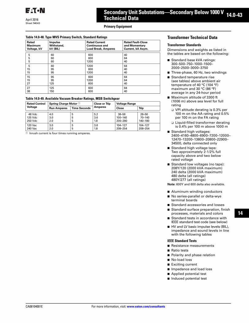
CA08104001E For more information, visit: www.eaton.com/consultants
14.0-43April 2016
Secondary Unit Substations—Secondary Below 1000 V
Sheet 14
i
ii
1
2
3
4
5
6
7
8
9
10
11
12
13
14
15
16
17
18
19
20
21
Technical DataPrimary Equipment
043
Table 14.0-48. Type MVS Primary Switch, Standard Ratings
Table 14.0-49. Available Vacuum Breaker Ratings, MSB Switchgear
1 Inrush current is four times running amperes.
Rated
Maximum
Voltage, kV
Impulse
Withstand,
kV (BIL)
Rated Current
Continuous and
Load Break, Amperes
Rated Fault-Close
and Momentary
Current, kA Asym.
555
606060
600600
1200
406440
51515
609595
1200600
1200
644040
151527
9595
125
6001200600
646440
2738
125150
600600
6440
Rated Control
Voltage
Spring Charge Motor 1 Close or Trip
Amperes
Voltage Range
Run Amperes Time Seconds Close Trip
48 Vdc125 Vdc250 Vdc
4.03.02.0
555
5.23.61.8
38–56100–140200–280
28–5670–140
140–180
120 Vac240 Vac
3.02.0
55
3.61.8
104–127208–254
104–127208–254
Transformer Technical Data
Transformer StandardsDimensions and weights as listed in the tables are based on the following:
■ Standard base kVA ratings: 300–500–750–1000–1500–2000–2500–3000–3750
■ Three-phase, 60 Hz, two windings■ Standard temperature rise
(see tables) above ambient air temperature of 40 °C (104 °F) maximum and 30 °C (86 °F) average in any 24-hour period
■ Maximum altitude of 3300 ft (1006 m) above sea level for full rating❑ VPI altitude derating is 0.3% per
100 m on the AA rating and 0.5% per 100 m on the FA rating
❑ Liquid-filled transformer derating is 0.4% per 100 m above 1000 m
■ Standard high voltages: 2400–4160–4800–6900–7200–12000–12470–13200–13800–20800–22900–34500, delta connected only
■ Standard high voltage taps: Two approximately 2-1/2% full capacity above and two below rated voltage
■ Standard low voltages (no taps):208Y/120 (2000 kVA maximum)240 delta (2000 kVA maximum)480 delta (all ratings) 480Y/277 (all ratings)
Note: 600Y and 600 delta also available.
■ Aluminum winding conductors■ No series-parallel or delta-wye
terminal boards■ Standard accessories and losses■ Standard surface preparation, finish
processes, materials and colors■ Standard tests in accordance with
IEEE standard test code (see below)■ HV and LV basic impulse levels (BIL),
impedance and sound levels in line with the following tables
IEEE Standard Tests■ Resistance measurements■ Ratio tests■ Polarity and phase relation■ No-load loss■ Exciting current■ Impedance and load loss■ Applied potential test■ Induced potential test

14.0-44
For more information, visit: www.eaton.com/consultants CA08104001E
April 2016
Secondary Unit Substations—Secondary Below 1000 V
Sheet 14
i
ii
1
2
3
4
5
6
7
8
9
10
11
12
13
14
15
16
17
18
19
20
21
Technical DataTransformers
044
Table 14.0-50. Liquid-Filled Transformer Continuous kVA for Different Base Temperature Rise Ratings
Table 14.0-51. Dry-Type (Conventional VPE and VPI) Transformer Continuous kVA for Different Base Temperature Rise Ratings
Table 14.0-52. Dry-Type Cast Coil, Dura-Cast, and RESIBLOC Transformer Continuous kVA for Different Base Temperature Rise Ratings
Table 14.0-53. Three-Phase, Single Temperature kVA Ratings
Table 14.0-54. Three-Phase, Dual or Triple Temperature kVA Ratings 1
1 If 65 ºC Rise is the base rating, the 75 ºC slash rating will increase the kVA capacity by 12%.
Temperature Rise, °C,
Base Rating, OA
Transformer Base, kVA Continuous kVA Multiplier
65 °C OA 55 °C FA 65 °C FA
55 Below 25002500 and larger
1.1201.120
1.1501.250
1.2901.400
65 Below 25002500 and larger
1.0001.000
N/AN/A
1.1501.250
Temperature Rise, °C,
Base Rating, AA
Continuous kVA Multiplier
80 °C AA 115 °C AA 150 °C AA 80 °C FA 115 °C FA 150 °C FA
80115150
1.000N/AN/A
1.1501.00N/A
1.3301.1501.00
1.330N/AN/A
1.5001.330N/A
1.8001.5001.330
Temperature Rise, °C,
Base Rating, AA
Type Continuous kVA Multiplier
80 °C AA 100 °C AA 115 °C AA 80 °C FA 100 °C FA 115 °C FA
80100115
Cast Coil or Dura-Cast
1.000N/AN/A
1.1201.000N/A
1.1701.0501.000
1.330N/AN/A
1.4501.330N/A
1.5001.3801.330
80 RESIBLOC 1.000 N/A N/A 1.330 N/A N/A
Three-Phase kVA Self-Cooled and Forced-Air Cooled with 75 ºC Temperature Rise
75 ºC Rise KNAN 75 ºC Rise KNAN/KNAF
500750
100015002000
+15% —863
115017252300
2500375050007500
10,000
+25% 3125468862509375
12,500
12,000 +33% 16,000
Three-Phase kVA Self-Cooled and Forced-Air Cooled with PEAK Triple Rated 55 ºC/75 ºC Temperature Rise
55 ºC Rise
KNAN
65 ºC Rise
KNAN
75 ºC Rise
KNAN
55 ºC Rise
KNAN/KNAF
65 ºC Rise
KNAN/KNAF
75 ºC RiseKNAN/KNAF
500750
1000
+12% 560840
1120
+9% 610916
1221
—863
1150
—966
1288
—10531404
150020002500
168022402800
183124423052
172523003125
193225763500
210628083815
375050007500
420056008400
457861049156
468862509375
52507000
10,500
51237630
11,445
10,00012,000
11,20013,440
12,20814,650
12,50016,000
14,90017,920
15,26016,533

CA08104001E For more information, visit: www.eaton.com/consultants
14.0-45April 2016
Secondary Unit Substations—Secondary Below 1000 V
Sheet 14
i
ii
1
2
3
4
5
6
7
8
9
10
11
12
13
14
15
16
17
18
19
20
21
Technical DataTransformers
045
Table 14.0-55. Secondary Short-Circuit Capacity of Typical Power Transformers
1 Short-circuit capacity values shown correspond to kVA and impedances shown in this table. For impedances other than these, short-circuit currents are inversely proportional to impedance.
2 The motor’s short-circuit current contributions are computed on the basis of motor characteristics that will give four times normal current. For 208 V, 50% motor load is assumed while for other voltages 100% motor load is assumed. For other percentages, the motor short-circuit current will be in direct proportion.
Trans-
former
Rating
Three-
Phase
kVA and
Impe-
dance
%
Maximum
Short-
Circuit
kVA
Available
from
Primary
System
208 V, Three-Phase 240 V, Three-Phase 480 V, Three-Phase 600 V, Three-Phase
Rated
Load
Contin-
uous
Current,
Amps
Short-Circuit Current
rms (Symmetrical
Amperes)
Rated
Load
Contin-
uous
Current,
Amps
Short-Circuit Current
rms (Symmetrical
Amperes)
Rated
Load
Contin-
uous
Current,
Amps
Short-Circuit Current
rms (Symmetrical
Amperes)
Rated
Load
Contin-
uous
Current,
Amps
Short-Circuit Current
rms (Symmetrical
Amperes)
Trans-
former
Alone 1
50%
Motor
Load2
Com-
bined
Trans-
former
Alone 1
100%
Motor
Load2
Com-
bined
Trans-
former
Alone 1
100%
Motor
Load2
Com-
bined
Trans-
former
Alone 1
100%
Motor
Load2
Com-
bined
3005%
50,000100,000150,000250,000500,000Unlimited
834 14,90015,70016,00016,30016,50016,700
1700 16,60017,40017,70018,00018,20018,400
722 12,9013,6013,9014,1014,30014,400
2900 15,80016,50016,80017,00017,20017,300
361 6,4006,8006,9007,0007,1007,200
1400 7,8008,2008,3008,4008,5008,600
289 5,2005,5005,6005,6005,7005,800
1200 6,4006,7006,8006,8006,9007,000
5005%
50,000100,000150,000250,000500,000Unlimited
1388 21,30025,20026,00026,70027,20027,800
2800 25,90028,00028,80029,50030,00030,600
1203 20,00021,90022,50023,10023,60024,100
4800 24,80026,70027,30027,90028,40028,900
601 10,00010,90011,30011,60011,80012,000
2400 12,40013,30013,70014,00014,20014,400
481 8,0008,7009,0009,3009,4009,600
1900 9,90010,60010,90011,20011,30011,500
7505.75%
50,000100,000150,000250,000500,000Unlimited
2080 28,70032,00033,30034,40035,20036,200
4200 32,90036,20037,50038,60039,40040,400
1804 24,90027,80028,90029,80030,60031,400
7200 32,10035,00036,10037,00037,80038,600
902 12,40013,90014,40014,90015,30015,700
3600 16,00017,50018,00018,50018,90019,300
722 10,00011,10011,60011,90012,20012,600
2900 12,90014,00014,50014,80015,10015,500
10005.75%
50,000100,000150,000250,000500,000Unlimited
2776 35,90041,20043,30045,20046,70048,300
5600 41,50046,80048,90050,80052,30053,900
2406 31,00035,60037,50039,10040,40041,800
6900 40,60045,20047,10048,70050,00051,400
1203 15,50017,80018,70019,60020,20020,900
4800 20,30022,60023,50024,40025,00025,700
962 12,40014,30015,00015,60016,20016,700
3900 16,30018,20018,90019,50020,10020,600
15005.75%
50,000100,000150,000250,000500,000Unlimited
4164 47,60057,50061,80065,60068,80072,500
8300 55,90065,80070,10073,90077,10080,800
3609 41,20049,80053,50056,80059,60062,800
14,400 55,60064,20057,90071,20074,00077,200
1804 20,60024,90026,70028,40029,80031,400
7200 27,80032,10033,90035,60037,00038,600
1444 16,50020,00021,40022,70023,90025,100
5800 22,30025,80027,20028,50029,70030,900
20005.75%
50,000100,000150,000250,000500,000Unlimited
— ——————
— ——————
— ——————
— ——————
2406 24,70031,00034,00036,70039,10041,800
9600 34,30040,60043,60046,30048,70051,400
1924 19,70024,80027,20029,40031,30033,500
7800 27,50032,60035,00037,20039,10041,300
25005.75%
50,000100,000150,000250,000500,000Unlimited
— ——————
— ——————
— ——————
— ——————
3008 28,00036,50040,50044,60048,10052,300
12,000 40,00048,50052,50056,60060,10064,300
2405 22,40029,20032,40035,60038,50041,800
9600 32,00038,80042,00045,20048,10051,400
30005.75%
50,000100,000150,000250,000500,000Unlimited
— ——————
— ——————
— ——————
— ——————
3609 30,70041,20046,60051,90056,80062,800
14,000 44,70055,20060,60065,90070,80076,800
2886 24,60033,00037,30041,50045,50050,200
11,500 36,10044,50048,80053,00057,00061,700
37505.75%
50,000100,000150,000250,000500,000Unlimited
— ——————
— ——————
— ——————
— ——————
4511 34,00047,50054,70062,20069,40078,500
18,000 52,00065,50072,70080,20087,40096,500
3608 27,20038,00043,70049,80055,50062,800
14,400 41,60052,40058,10064,20069,90077,200
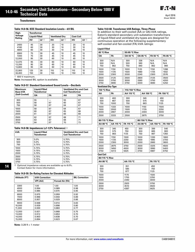
14.0-46
For more information, visit: www.eaton.com/consultants CA08104001E
April 2016
Secondary Unit Substations—Secondary Below 1000 V
Sheet 14
i
ii
1
2
3
4
5
6
7
8
9
10
11
12
13
14
15
16
17
18
19
20
21
Technical DataTransformers
046
Table 14.0-56. IEEE Standard Insulation Levels—kV BIL
1 600 V maximum.Note: Increased BIL option is available.
Table 14.0-57. Standard Guaranteed Sound Levels—Decibels
Table 14.0-58. Impedances (±7-1/2% Tolerance) 2
2 Optional impedance values are available up to 8.0%. Contact Eaton for more information.
Table 14.0-59. De-Rating Factors for Elevated Altitudes
Note: 3.28 ft = 1 meter
Table 14.0-60. Transformer kVA Ratings, Three-PhaseIn addition to their self-cooled (AA or OA) kVA ratings, Eaton’s standard secondary unit substation transformers of liquid-filled and ventilated dry-types are designed for continuous operation at the following supplementary self-cooled and fan-cooled (FA) kVA ratings:
Liquid-Filled
Ventilated Dry-Type
Cast Coil
High-
Voltage
Rating
Transformer
Liquid-Filled Ventilated Dry Cast Coil
HV LV 1 HV LV 1 HV LV 1
240041604800
456060
303030
203030
101010
203030
101010
69007200
12,000
757595
303030
454560
101010
454560
101010
12,47013,20013,800
959595
303030
606060
101010
606060
101010
22,90034,400
125150
3030
110150
1010
110150
1010
Maximum
Base kVA
(Self-Cooled)
Liquid-Filled
Transformer
Ventilated Dry and Cast
Coil Transformer
OA FA AA FA
300500750
555658
—6767
556064
676767
100015002000
586061
676767
646566
676869
250030003750
626364
676767
686870
717173
kVA Liquid-Filled
Transformer
Ventilated Dry and Cast
Coil Transformer
300500750
5.0%5.0%5.75%
5.75%5.75%5.75%
100015002000
5.75%5.75%5.75%
5.75%5.75%5.75%
250030003750
5.75%5.75%5.75%
5.75%5.75%5.75%
Altitude (FT) kVA Correction BIL Correction
VPI (AA) Forced Air (FA)
330040005000
1.000.9940.985
1.000.9890.974
1.000.980.95
600070008000
0.9750.9660.957
0.9590.9440.929
0.920.890.86
900010,00011,000
0.9480.9390.930
0.9140.8980.883
0.830.800.77
12,00013,00014,00015,000
0.9210.9120.9030.894
0.8680.8530.8380.823
0.750.700.700.67
65 °C Rise 55/65 °C Rise
OA FA OA 55 °C OA 65 °C FA 55 °C FA 65 °C
300500750
N/AN/A862
300500750
336560840
N/AN/A862
N/AN/A966
100015002000
115017252300
100015002000
112016802240
115017252300
128819322576
250030003750
312537504690
250030003750
280033604200
312537504690
350042005250
150 °C Rise 115/150 °C Rise
AA FA AA 115 °C AA 150 °C FA 150 °C
300500750
400667
1000
300500750
345575863
450750
1125
100015002000
133320002667
100015002000
115017252300
150022503000
2500 3333 2500 2875 3750
80/115 °C Rise 80/150 °C Rise
AA 80 °C AA 115 °C FA 115 °C AA 80 °C AA 150 °C FA 150 °C
300500750
345575863
450750
1125
300500750
399665997
540900
1350
100015002000
115017252300
150022503000
100015002000
133019952660
180027003600
250030003750
287534504313
375045005625
250030003750
332539904987
450054006750
80/115 °C Rise
AA 80 °C AA 115 °C FA 115 °C
300500750
351585877
450750
1125
100015002000
117017552340
150022503000
250030003750
292535104387
375045005625

CA08104001E For more information, visit: www.eaton.com/consultants
14.0-47April 2016
Secondary Unit Substations—Secondary Below 1000 V
Sheet 14
i
ii
1
2
3
4
5
6
7
8
9
10
11
12
13
14
15
16
17
18
19
20
21
Technical DataSecondary Equipment
047
Secondary EquipmentFor information on secondary equipment for use in unit substations, refer to the following tabs of the Consulting Application Guide:
Tab 20—Low Voltage Metal-Enclosed Drawout Switchgear
Tab 21—Low Voltage Switchboards
Tab 26—Power Circuit Breakers and Insulated-Case Circuit Breakers
Tab 27—Molded-Case Circuit Breakers and Enclosures

14.0-48
For more information, visit: www.eaton.com/consultants CA08104001E
April 2016
Secondary Unit Substations—Secondary Below 1000 V
Sheet 14
i
ii
1
2
3
4
5
6
7
8
9
10
11
12
13
14
15
16
17
18
19
20
21
048
This page intentionally left blank.