second-generation stack computer architecture -...
TRANSCRIPT

Second-Generation Stack ComputerArchitecture
Charles Eric LaForest
A thesispresented to the Independent Studies Program
of the University of Waterlooin fulfilment of the
thesis requirements for the degreeBachelor of Independent Studies (BIS)
Independent StudiesUniversity of Waterloo
CanadaApril 2007

ii

Declaration
I hereby declare that I am the sole author of this research paper.
I authorize the University of Waterloo to lend this thesis toother institutions or individuals forthe purpose of scholarly research.
Signature:
I further authorize the University of Waterloo to reproducethis research paper by photocopy-ing or other means, in total or in part, at the request of otherinstitutions or individuals for thepurpose of scholarly research.
Signature:
The work in this research paper is based on research carried out in the Independent StudiesProgram at the University of Waterloo, Canada. No part of this thesis has been submitted else-where for any other degree or qualification and is all my own work unless referenced to thecontrary in the text.
Copyright c© 2007 by Charles Eric LaForest.The copyright of this thesis rests with the author. Quotations and information derived from itmust be acknowledged.
iii

Second-Generation Stack Computer Architecture
Charles Eric LaForest
Submitted for the degree of Bachelor of Independent StudiesApril 2007
Abstract
It is commonly held in current computer architecture literature that stack-based computers wereentirely superseded by the combination of pipelined, integrated microprocessors and improvedcompilers. While correct, the literature omits a second, new generation of stack computersthat emerged at the same time. In this thesis, I develop historical, qualitative, and quantitativedistinctions between the first and second generations of stack computers. I present a rebuttalof the main arguments against stack computers and show that they are not applicable to thoseof the second generation. I also present an example of a small, modern stack computer andcompare it to the MIPS architecture. The results show that second-generation stack computershave much better performance for deeply nested or recursivecode, but are correspondinglyworse for iterative code. The results also show that even though the stack computer’s zero-operand instruction format only moderately increases the code density, it significantly reducesinstruction memory bandwidth.
iv

Acknowledgements
Firstly, thanks go to my family, immediate and extended, whohave always given me the leewayand support I needed, who always believed in me.
Sometime in 2000, Ralph Siemsen and Andrew E. Mileski introduced me to the Forthprogramming language, which changed my view of programming. Soon after, I discovered themicroprocessors of Chen-Hanson Ting, Jeff Fox, and CharlesH. (Chuck) Moore, which didthe same for my view of computer hardware. Aaron Holtzman suggested I play with FPGAsimulations of these computers, and graciously bore all my grumblings about broken Verilogcompilers. At the same time, I had stimulating email discussions with Myron Plichota andJecel Mattos de Assumpcao Jr. which led to some of the new ideas in this thesis.
It was Sheryl Cronk who eventually gave me the arguments and reasons to return to Uni-versity. Many friends bought my old junk and helped me move. For this kick-start and support,I am forever grateful.
Once at Waterloo, Professor Chrysanne DiMarco became my Adviser. Her thorough knowl-edge of the English language and of the customs of academia improved me greatly. Thus, Imust atone by myself for any linguistic errors in this thesis. Professors Giuseppe Tenti andBarry Ferguson unrusted and expanded my mathematical skills. Professor Manoj Sachdev andhis PhD students, Shahab Ardalan and Bhaskar Chatterjee, took much time both inside andoutside of class to discuss the details of VLSI circuitry with me. Professors Mark Aagaardhelped me gain a broader perspective on computer architecture and led me to the class of Pro-fessor Paul Dasiewicz who taught me more about the subject. PhD candidate Brad Lushmantook time to help me with my exploration of programming languages. I also thank ProfessorAnne Innis Dagg of Independent Studies, whose course on independent research rounded meout well.
Outside of class, the denizens of the Computer Science Club provided both enthusiasticdiscussions and gave me a chance to make my work heard. Mike Jeays provided me with auseful and rare primary source for the KDF9, his favourite computer. Professor Steven M.Nowick of Columbia University helped me understand his MINIMALIST synthesis tool.
The wheels of Independent Studies were kept turning by Professors Bill Abbott and RichardHolmes and especially by Susan Gow, who provided endless enthusiasm, countless good ex-amples, and sage advice.
The writing of this thesis was supervised by Dr. Andrew Morton here at Waterloo, and byProfessor J. Gregory Steffan of the University of Toronto. Iam very grateful for their feedbackand guidance.
And finally, thanks to Joy, my fiancée. You brighten my life. You make me happy.The years ahead with you glow with promise and adventure.
v

”But the speed was power, and the speed was joy, and the speed was pure beauty.”
– Richard Bach,Johnathan Livingston Seagull
“If my calculations are correct, when this baby hits eighty-eight miles per hour,you’re gonna see some serious shit.”
– Emmet “Doc” Brown, inBack To The Future
vi
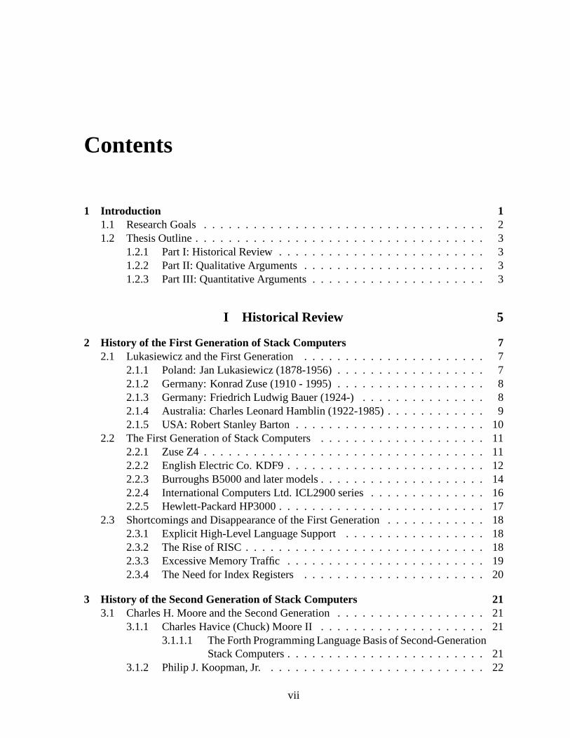
Contents
1 Introduction 11.1 Research Goals . . . . . . . . . . . . . . . . . . . . . . . . . . . . . . . . . . 21.2 Thesis Outline . . . . . . . . . . . . . . . . . . . . . . . . . . . . . . . . . . .3
1.2.1 Part I: Historical Review . . . . . . . . . . . . . . . . . . . . . . . .. 31.2.2 Part II: Qualitative Arguments . . . . . . . . . . . . . . . . . . .. . . 31.2.3 Part III: Quantitative Arguments . . . . . . . . . . . . . . . . .. . . . 3
I Historical Review 5
2 History of the First Generation of Stack Computers 72.1 Lukasiewicz and the First Generation . . . . . . . . . . . . . . . .. . . . . . 7
2.1.1 Poland: Jan Lukasiewicz (1878-1956) . . . . . . . . . . . . . .. . . . 72.1.2 Germany: Konrad Zuse (1910 - 1995) . . . . . . . . . . . . . . . . .. 82.1.3 Germany: Friedrich Ludwig Bauer (1924-) . . . . . . . . . . .. . . . 82.1.4 Australia: Charles Leonard Hamblin (1922-1985) . . . .. . . . . . . . 92.1.5 USA: Robert Stanley Barton . . . . . . . . . . . . . . . . . . . . . . .10
2.2 The First Generation of Stack Computers . . . . . . . . . . . . . .. . . . . . 112.2.1 Zuse Z4 . . . . . . . . . . . . . . . . . . . . . . . . . . . . . . . . . . 112.2.2 English Electric Co. KDF9 . . . . . . . . . . . . . . . . . . . . . . . .122.2.3 Burroughs B5000 and later models . . . . . . . . . . . . . . . . . .. . 142.2.4 International Computers Ltd. ICL2900 series . . . . . . .. . . . . . . 162.2.5 Hewlett-Packard HP3000 . . . . . . . . . . . . . . . . . . . . . . . . .17
2.3 Shortcomings and Disappearance of the First Generation. . . . . . . . . . . . 182.3.1 Explicit High-Level Language Support . . . . . . . . . . . . .. . . . 182.3.2 The Rise of RISC . . . . . . . . . . . . . . . . . . . . . . . . . . . . . 182.3.3 Excessive Memory Traffic . . . . . . . . . . . . . . . . . . . . . . . . 192.3.4 The Need for Index Registers . . . . . . . . . . . . . . . . . . . . . .20
3 History of the Second Generation of Stack Computers 213.1 Charles H. Moore and the Second Generation . . . . . . . . . . . .. . . . . . 21
3.1.1 Charles Havice (Chuck) Moore II . . . . . . . . . . . . . . . . . . .. 213.1.1.1 The Forth Programming Language Basis of Second-Generation
Stack Computers . . . . . . . . . . . . . . . . . . . . . . . . 213.1.2 Philip J. Koopman, Jr. . . . . . . . . . . . . . . . . . . . . . . . . . . 22
vii

3.2 The Second Generation of Stack Computers . . . . . . . . . . . . .. . . . . . 233.2.1 NOVIX NC4016 . . . . . . . . . . . . . . . . . . . . . . . . . . . . . 233.2.2 Harris RTX-2000 . . . . . . . . . . . . . . . . . . . . . . . . . . . . . 233.2.3 Sh-BOOM (Patriot Scientific IGNITE I) . . . . . . . . . . . . . .. . . 233.2.4 MuP21 . . . . . . . . . . . . . . . . . . . . . . . . . . . . . . . . . . 253.2.5 F21 . . . . . . . . . . . . . . . . . . . . . . . . . . . . . . . . . . . . 263.2.6 c18 . . . . . . . . . . . . . . . . . . . . . . . . . . . . . . . . . . . . 26
3.3 Recent Research . . . . . . . . . . . . . . . . . . . . . . . . . . . . . . . . . .263.4 Strengths and Weaknesses of the Second Generation . . . . .. . . . . . . . . 28
3.4.1 The Need for Index Registers . . . . . . . . . . . . . . . . . . . . . .283.4.2 Stack Manipulation Overhead . . . . . . . . . . . . . . . . . . . . .. 283.4.3 Poor Support of ALGOL-like Languages . . . . . . . . . . . . . .. . 293.4.4 Reduced Instruction Memory Bandwidth and System Complexity . . . 293.4.5 Fast Subroutine Linkage and Interrupt Response . . . . .. . . . . . . 29
II Qualitative Arguments 31
4 Distinguishing the First and Second Generations 334.1 Location of Stacks: In-Memory vs. In-Processor . . . . . . .. . . . . . . . . 344.2 Use of Stacks: Procedure Nesting vs. Expression Evaluation . . . . . . . . . . 354.3 Operations with Stacks: High-Level Language Support vs. Primitive Operations 36
5 Objections Cited by Hennessy & Patterson 375.1 The Enormous Influence of Hennessy & Patterson on Computer Architecture . 375.2 The Disappearance of Stack Computers (of the First Generation) . . . . . . . . 385.3 Expression Evaluation on a Stack . . . . . . . . . . . . . . . . . . . .. . . . . 395.4 The Use of the Stack for Holding Variables . . . . . . . . . . . . .. . . . . . 405.5 Distorted Historical Arguments . . . . . . . . . . . . . . . . . . . .. . . . . . 40
III Quantitative Arguments 45
6 A Stack-Based Counterpart to DLX: Gullwing 476.1 Block Diagram . . . . . . . . . . . . . . . . . . . . . . . . . . . . . . . . . . 47
6.1.1 Memory Subsystem . . . . . . . . . . . . . . . . . . . . . . . . . . . 486.1.1.1 Single Memory Bus . . . . . . . . . . . . . . . . . . . . . . 486.1.1.2 Differentiating Loads, Stores, and Fetches . . . . . .. . . . 48
6.1.2 Computation Subsystem . . . . . . . . . . . . . . . . . . . . . . . . . 486.1.3 Control Subsystem . . . . . . . . . . . . . . . . . . . . . . . . . . . . 48
6.2 Instruction Set . . . . . . . . . . . . . . . . . . . . . . . . . . . . . . . . . .. 496.2.1 Instruction Packing . . . . . . . . . . . . . . . . . . . . . . . . . . . .496.2.2 Flow Control . . . . . . . . . . . . . . . . . . . . . . . . . . . . . . . 496.2.3 Load, Store, and Literal Fetch . . . . . . . . . . . . . . . . . . . .. . 506.2.4 Arithmetic and Logic . . . . . . . . . . . . . . . . . . . . . . . . . . . 50
viii
6.2.4.1 Synthesizing More Complex Operations . . . . . . . . . . .516.2.5 Stack Manipulation . . . . . . . . . . . . . . . . . . . . . . . . . . . . 526.2.6 No-Op and Undefined . . . . . . . . . . . . . . . . . . . . . . . . . . 526.2.7 Instruction Format and Execution Example . . . . . . . . . .. . . . . 53
6.3 State Machine and Register Transfer Description . . . . . .. . . . . . . . . . 546.3.1 Improvement: Instruction Fetch Overlap . . . . . . . . . . .. . . . . . 56
7 Comparisons With DLX/MIPS 597.1 Gullwing Benchmarks . . . . . . . . . . . . . . . . . . . . . . . . . . . . . .59
7.1.1 Flight Language Kernel (Bare) . . . . . . . . . . . . . . . . . . . .. . 597.1.2 Flight Language Extensions (Ext.) . . . . . . . . . . . . . . . .. . . . 607.1.3 Virtual Machine (VM) . . . . . . . . . . . . . . . . . . . . . . . . . . 60
7.2 Comparison of Executed Benchmark Code . . . . . . . . . . . . . . .. . . . . 617.2.1 Dynamic Instruction Mix . . . . . . . . . . . . . . . . . . . . . . . . .617.2.2 Cycles Per Instruction . . . . . . . . . . . . . . . . . . . . . . . . . .647.2.3 Memory Accesses Per Cycle . . . . . . . . . . . . . . . . . . . . . . . 657.2.4 Instructions per Memory Word . . . . . . . . . . . . . . . . . . . . .. 67
7.2.4.1 Basic Blocks and Instruction Fetch Overhead . . . . . .. . . 687.3 Behaviour of Iteration, Recursion, and Subroutine Calls . . . . . . . . . . . . . 68
7.3.1 Measured Properties . . . . . . . . . . . . . . . . . . . . . . . . . . . 687.3.2 Demonstrators . . . . . . . . . . . . . . . . . . . . . . . . . . . . . . 697.3.3 Iterative Triangular Numbers . . . . . . . . . . . . . . . . . . . .. . . 707.3.4 Recursive Triangular Numbers . . . . . . . . . . . . . . . . . . . .. . 727.3.5 Tail-recursive Triangular Numbers . . . . . . . . . . . . . . .. . . . . 747.3.6 Subroutine Calls . . . . . . . . . . . . . . . . . . . . . . . . . . . . . 76
7.4 Pipelining . . . . . . . . . . . . . . . . . . . . . . . . . . . . . . . . . . . . . 797.4.1 Transforming the DLX Pipeline to Gullwing . . . . . . . . . .. . . . 797.4.2 Altering the ISR to Deal with the Additional Latency . .. . . . . . . . 817.4.3 The Effect of Pipelining on Calls, Jumps, and the CPI . .. . . . . . . 83
7.5 Summary and Performance Comparison . . . . . . . . . . . . . . . . .. . . . 84
8 Improving Code Density 858.1 Improving High-Level Code Density by Adding an Instruction Stack . . . . . . 86
8.1.1 Side-Effects on Return Stack Manipulation . . . . . . . . .. . . . . . 878.2 Implementation . . . . . . . . . . . . . . . . . . . . . . . . . . . . . . . . . .888.3 Side-Effect on Code Size, Silicon Area, and Subroutine Overhead . . . . . . . 88
8.3.1 The Instruction Stack as an Instruction Cache . . . . . . .. . . . . . . 89
9 Conclusions, Contributions, and Further Work 919.1 Contributions . . . . . . . . . . . . . . . . . . . . . . . . . . . . . . . . . . .939.2 Further Work . . . . . . . . . . . . . . . . . . . . . . . . . . . . . . . . . . . 93
9.2.1 Reducing the DLX/MIPS Subroutine Call Overhead by Adding Stacks 949.2.2 Reducing Gullwing’s Instruction Count with CompoundStack Opera-
tions . . . . . . . . . . . . . . . . . . . . . . . . . . . . . . . . . . . . 96
ix
9.2.3 Reducing Gullwing’s CPI by Executing Multiple Instructions usingGeneralized Instruction Folding . . . . . . . . . . . . . . . . . . . . . 97
A Gullwing Benchmarks Source 99A.1 Flight Language Kernel . . . . . . . . . . . . . . . . . . . . . . . . . . . .. . 99
A.1.1 Internal Variables and Memory Map . . . . . . . . . . . . . . . . .. . 99A.1.1.1 Counted Strings . . . . . . . . . . . . . . . . . . . . . . . . 100
A.1.2 Utility Functions . . . . . . . . . . . . . . . . . . . . . . . . . . . . . 101A.1.3 String Functions . . . . . . . . . . . . . . . . . . . . . . . . . . . . . 101A.1.4 Input Functions . . . . . . . . . . . . . . . . . . . . . . . . . . . . . . 102A.1.5 Name Lookup . . . . . . . . . . . . . . . . . . . . . . . . . . . . . . . 103A.1.6 Function Definition Functions . . . . . . . . . . . . . . . . . . . .. . 104A.1.7 Compilation Functions . . . . . . . . . . . . . . . . . . . . . . . . . .106A.1.8 Inline Compilation . . . . . . . . . . . . . . . . . . . . . . . . . . . . 108A.1.9 Main Loop . . . . . . . . . . . . . . . . . . . . . . . . . . . . . . . . 108A.1.10 Decimal to Binary Conversion . . . . . . . . . . . . . . . . . . . .. . 109
A.2 Flight Language Extensions . . . . . . . . . . . . . . . . . . . . . . . .. . . 109A.2.1 Making the Flight Language More Tractable . . . . . . . . . .. . . . 110A.2.2 Interactively Usable Opcodes . . . . . . . . . . . . . . . . . . . .. . 112A.2.3 Basic Compiling Functions . . . . . . . . . . . . . . . . . . . . . . .. 112A.2.4 Terminal Control Characters . . . . . . . . . . . . . . . . . . . . .. . 113A.2.5 Conditionals and Comparisons . . . . . . . . . . . . . . . . . . . .. . 113A.2.6 Code Memory Allocation . . . . . . . . . . . . . . . . . . . . . . . . 115A.2.7 String Copying and Printing . . . . . . . . . . . . . . . . . . . . . .. 115A.2.8 De-Allocating Functions . . . . . . . . . . . . . . . . . . . . . . . .. 116A.2.9 Unsigned Multiplication and Division . . . . . . . . . . . . .. . . . . 117A.2.10 Binary to Decimal Conversion . . . . . . . . . . . . . . . . . . . .. . 118A.2.11 Simple Fibonacci Examples . . . . . . . . . . . . . . . . . . . . . .. 119A.2.12 Static Variables . . . . . . . . . . . . . . . . . . . . . . . . . . . . . .120A.2.13 Accumulator Generator . . . . . . . . . . . . . . . . . . . . . . . . .. 121A.2.14 Fibonacci Generator . . . . . . . . . . . . . . . . . . . . . . . . . . .121A.2.15 Caesar Cipher Generator . . . . . . . . . . . . . . . . . . . . . . . .. 122A.2.16 Higher-Order Function (Map) . . . . . . . . . . . . . . . . . . . .. . 124
A.3 Virtual Machine . . . . . . . . . . . . . . . . . . . . . . . . . . . . . . . . . .125A.3.1 VM . . . . . . . . . . . . . . . . . . . . . . . . . . . . . . . . . . . . 125A.3.2 Metacompiler . . . . . . . . . . . . . . . . . . . . . . . . . . . . . . . 131A.3.3 Self-hosted Kernel . . . . . . . . . . . . . . . . . . . . . . . . . . . . 135A.3.4 Flight Language Extensions . . . . . . . . . . . . . . . . . . . . . .. 140
B Static and Dynamic Gullwing Code Analyses 141B.1 Static Analyses . . . . . . . . . . . . . . . . . . . . . . . . . . . . . . . . . .141
B.1.1 Memory Usage . . . . . . . . . . . . . . . . . . . . . . . . . . . . . . 141B.1.2 Range of Literals . . . . . . . . . . . . . . . . . . . . . . . . . . . . . 142B.1.3 Range of Addresses . . . . . . . . . . . . . . . . . . . . . . . . . . . . 142B.1.4 Instructions per Instruction Word . . . . . . . . . . . . . . . .. . . . 143
x

B.1.5 Instruction Density . . . . . . . . . . . . . . . . . . . . . . . . . . . .143B.1.6 Compiled Instruction Counts . . . . . . . . . . . . . . . . . . . . .. . 144
B.2 Dynamic Analyses . . . . . . . . . . . . . . . . . . . . . . . . . . . . . . . . 145B.2.1 Overall Execution . . . . . . . . . . . . . . . . . . . . . . . . . . . . 145B.2.2 Executed Instruction Counts . . . . . . . . . . . . . . . . . . . . .. . 145B.2.3 Average CPI . . . . . . . . . . . . . . . . . . . . . . . . . . . . . . . 147B.2.4 Instruction Types . . . . . . . . . . . . . . . . . . . . . . . . . . . . . 147B.2.5 Basic Block Length . . . . . . . . . . . . . . . . . . . . . . . . . . . . 148B.2.6 Data Stack Depth . . . . . . . . . . . . . . . . . . . . . . . . . . . . . 149B.2.7 Return Stack Depth . . . . . . . . . . . . . . . . . . . . . . . . . . . . 150
Bibliography 151
xi

xii
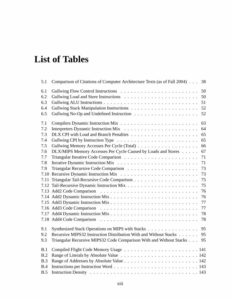
List of Tables
5.1 Comparison of Citations of Computer Architecture Texts(as of Fall 2004) . . . 38
6.1 Gullwing Flow Control Instructions . . . . . . . . . . . . . . . . .. . . . . . 506.2 Gullwing Load and Store Instructions . . . . . . . . . . . . . . . .. . . . . . 506.3 Gullwing ALU Instructions . . . . . . . . . . . . . . . . . . . . . . . . .. . . 516.4 Gullwing Stack Manipulation Instructions . . . . . . . . . . .. . . . . . . . . 526.5 Gullwing No-Op and Undefined Instruction . . . . . . . . . . . . .. . . . . . 52
7.1 Compilers Dynamic Instruction Mix . . . . . . . . . . . . . . . . . .. . . . . 637.2 Interpreters Dynamic Instruction Mix . . . . . . . . . . . . . . .. . . . . . . 647.3 DLX CPI with Load and Branch Penalties . . . . . . . . . . . . . . . .. . . . 657.4 Gullwing CPI by Instruction Type . . . . . . . . . . . . . . . . . . . .. . . . 657.5 Gullwing Memory Accesses Per Cycle (Total) . . . . . . . . . . .. . . . . . . 667.6 DLX/MIPS Memory Accesses Per Cycle Caused by Loads and Stores . . . . . 677.7 Triangular Iterative Code Comparison . . . . . . . . . . . . . . .. . . . . . . 717.8 Iterative Dynamic Instruction Mix . . . . . . . . . . . . . . . . . .. . . . . . 717.9 Triangular Recursive Code Comparison . . . . . . . . . . . . . . .. . . . . . 737.10 Recursive Dynamic Instruction Mix . . . . . . . . . . . . . . . . .. . . . . . 737.11 Triangular Tail-Recursive Code Comparison . . . . . . . . .. . . . . . . . . . 757.12 Tail-Recursive Dynamic Instruction Mix . . . . . . . . . . . .. . . . . . . . . 757.13 Add2 Code Comparison . . . . . . . . . . . . . . . . . . . . . . . . . . . . .767.14 Add2 Dynamic Instruction Mix . . . . . . . . . . . . . . . . . . . . . .. . . . 767.15 Add3 Dynamic Instruction Mix . . . . . . . . . . . . . . . . . . . . . .. . . . 777.16 Add3 Code Comparison . . . . . . . . . . . . . . . . . . . . . . . . . . . . .777.17 Add4 Dynamic Instruction Mix . . . . . . . . . . . . . . . . . . . . . .. . . . 787.18 Add4 Code Comparison . . . . . . . . . . . . . . . . . . . . . . . . . . . . .78
9.1 Synthesized Stack Operations on MIPS with Stacks . . . . . .. . . . . . . . . 959.2 Recursive MIPS32 Instruction Distribution With and Without Stacks . . . . . . 959.3 Triangular Recursive MIPS32 Code Comparison With and Without Stacks . . . 95
B.1 Compiled Flight Code Memory Usage . . . . . . . . . . . . . . . . . . .. . . 141B.2 Range of Literals by Absolute Value . . . . . . . . . . . . . . . . . .. . . . . 142B.3 Range of Addresses by Absolute Value . . . . . . . . . . . . . . . . .. . . . . 142B.4 Instructions per Instruction Word . . . . . . . . . . . . . . . . . .. . . . . . . 143B.5 Instruction Density . . . . . . . . . . . . . . . . . . . . . . . . . . . . . .. . 143
xiii

B.6 Compiled Instruction Counts . . . . . . . . . . . . . . . . . . . . . . .. . . . 144B.7 Overall Execution . . . . . . . . . . . . . . . . . . . . . . . . . . . . . . . .. 145B.8 Executed Instruction Counts . . . . . . . . . . . . . . . . . . . . . . .. . . . 146B.9 Average CPI . . . . . . . . . . . . . . . . . . . . . . . . . . . . . . . . . . . . 147B.10 Instruction Types . . . . . . . . . . . . . . . . . . . . . . . . . . . . . . .. . 147B.11 Basic Block Length . . . . . . . . . . . . . . . . . . . . . . . . . . . . . . .. 148B.12 Data Stack Depth . . . . . . . . . . . . . . . . . . . . . . . . . . . . . . . . .149B.13 Return Stack Depth . . . . . . . . . . . . . . . . . . . . . . . . . . . . . . .. 150
xiv

List of Figures
2.1 Evaluation of Polish Notation expression/ + 5 5 2 . . . . . . . . . . . . . . . 82.2 Fig. 1 from Bauer and Samelson German Patent #1094019 . . .. . . . . . . . 92.3 Programming model for the Zuse Z4 . . . . . . . . . . . . . . . . . . . .. . . 112.4 KDF9 Q-Store Layout . . . . . . . . . . . . . . . . . . . . . . . . . . . . . . 122.5 KDF9 Block Diagram . . . . . . . . . . . . . . . . . . . . . . . . . . . . . . . 132.6 B6900 Top-of-Stack and Stack Bounds Registers . . . . . . . .. . . . . . . . 152.7 B7700 Stack Buffer and Stack Memory Area . . . . . . . . . . . . . .. . . . 152.8 Comparison of B6700 and ICL 2900 stack mechanisms . . . . . .. . . . . . . 162.9 HP3000 Stack Registers . . . . . . . . . . . . . . . . . . . . . . . . . . . .. 17
3.1 NC4016 and RTX-2000 Block Diagrams . . . . . . . . . . . . . . . . . .. . . 243.2 IGNITE I Block Diagram . . . . . . . . . . . . . . . . . . . . . . . . . . . . .25
4.1 First-Generation Stack Computer Block Diagram . . . . . . .. . . . . . . . . 344.2 General-Purpose Register Computer Block Diagram . . . . .. . . . . . . . . . 344.3 Second-Generation Stack Computer Block Diagram . . . . . .. . . . . . . . . 35
6.1 Gullwing Block-Level Datapath . . . . . . . . . . . . . . . . . . . . .. . . . 476.2 Gullwing Instruction Shift Register Block Diagram . . . .. . . . . . . . . . . 476.3 Gullwing Instruction Format . . . . . . . . . . . . . . . . . . . . . . .. . . . 53
7.1 DLX Pipeline Block Diagram . . . . . . . . . . . . . . . . . . . . . . . . .. 797.2 Gullwing Pipeline Block Diagram . . . . . . . . . . . . . . . . . . . .. . . . 807.3 Gullwing Pipeline Operation . . . . . . . . . . . . . . . . . . . . . . .. . . . 817.4 Gullwing Load/Stores Pipeline Diagram . . . . . . . . . . . . . .. . . . . . . 817.5 Gullwing ISR Modified for Pipeline . . . . . . . . . . . . . . . . . . .. . . . 827.6 Gullwing Instruction Fetch (with Overlap) Pipeline Diagram . . . . . . . . . . 827.7 Gullwing Instruction Fetch (without Overlap) PipelineDiagram . . . . . . . . 837.8 Gullwing Taken Jumps or Calls Pipeline Diagram . . . . . . . .. . . . . . . . 83
8.1 Gullwing High-Level Code with Unavailable Slots . . . . . .. . . . . . . . . 858.2 Instruction Stack During Call and Return . . . . . . . . . . . . .. . . . . . . 868.3 Gullwing High-Level Code with Available Slots . . . . . . . .. . . . . . . . . 868.4 Instruction Stack During >R and R> . . . . . . . . . . . . . . . . . . .. . . . 87
9.1 MIPS Register File with Stacks . . . . . . . . . . . . . . . . . . . . . .. . . . 94
xv

A.1 Flight Language Kernel Memory Map . . . . . . . . . . . . . . . . . . .. . . 100A.2 Counted String Format . . . . . . . . . . . . . . . . . . . . . . . . . . . . .. 100
xvi

List of Algorithms
1 Gullwing Synthesis of Subtraction and Bitwise OR . . . . . . . .. . . . . . . 512 Gullwing Synthesis of Multiplication (4x4) . . . . . . . . . . . .. . . . . . . 513 Gullwing Flow Control Instructions . . . . . . . . . . . . . . . . . . .. . . . 544 Gullwing No-Op and Undefined Instructions . . . . . . . . . . . . . .. . . . . 545 Gullwing ALU Instructions . . . . . . . . . . . . . . . . . . . . . . . . . . .. 556 Gullwing Load and Store Instructions . . . . . . . . . . . . . . . . . .. . . . 557 Gullwing Stack Instructions . . . . . . . . . . . . . . . . . . . . . . . . .. . 558 Gullwing ALU Instructions with Instruction Fetch Overlap. . . . . . . . . . . 579 Gullwing Stack Instructions with Instruction Fetch Overlap . . . . . . . . . . . 5710 Gullwing No-Op and Undefined Instructions with Instruction Fetch Overlap . . 5711 Triangular Iterative C Source . . . . . . . . . . . . . . . . . . . . . . .. . . . 7112 Triangular Iterative MIPS32 Assembly . . . . . . . . . . . . . . . .. . . . . . 7113 Triangular Iterative Gullwing Assembly . . . . . . . . . . . . . .. . . . . . . 7114 Triangular Recursive C Source . . . . . . . . . . . . . . . . . . . . . . .. . . 7215 Triangular Recursive MIPS32 Assembly . . . . . . . . . . . . . . . .. . . . . 7316 Triangular Recursive Gullwing Assembly . . . . . . . . . . . . . .. . . . . . 7317 Triangular Tail-Recursive C Source . . . . . . . . . . . . . . . . . .. . . . . 7418 Triangular Tail-Recursive MIPS32 Assembly . . . . . . . . . . .. . . . . . . 7519 Triangular Tail-Recursive Gullwing Assembly . . . . . . . . .. . . . . . . . . 7520 Add2 C Source . . . . . . . . . . . . . . . . . . . . . . . . . . . . . . . . . . 7621 Add2 MIPS32 Assembly . . . . . . . . . . . . . . . . . . . . . . . . . . . . . 7622 Add2 Gullwing Assembly . . . . . . . . . . . . . . . . . . . . . . . . . . . . 7623 Add3 C Source . . . . . . . . . . . . . . . . . . . . . . . . . . . . . . . . . . 7724 Add3 MIPS32 Assembly . . . . . . . . . . . . . . . . . . . . . . . . . . . . . 7725 Add3 Gullwing Assembly . . . . . . . . . . . . . . . . . . . . . . . . . . . . 7726 Add4 C Source . . . . . . . . . . . . . . . . . . . . . . . . . . . . . . . . . . 7827 Add4 MIPS32 Assembly . . . . . . . . . . . . . . . . . . . . . . . . . . . . . 7828 Add4 Gullwing Assembly . . . . . . . . . . . . . . . . . . . . . . . . . . . . 7829 Alterations to Gullwing to Support an Instruction Stack .. . . . . . . . . . . . 8830 Triangular Recursive MIPS32 Assembly with Stacks Added .. . . . . . . . . 9531 Gullwing Compound Stack Operations . . . . . . . . . . . . . . . . . .. . . . 9632 Example Gullwing Instruction Sequence Using Generalized Folding . . . . . . 97
xvii

xviii

Chapter 1
Introduction
I first learnt about stack computers in 2000 while working at acomputer manufacturer whereco-workers introduced me to the Forth programming language, a stack-based programmingenvironment. Soon after, while looking for a suitable processor for a homebrew computersystem, I came across a mention of the MuP21 [MT95] in the Usenet Embedded Processorand Microcontroller Primer and FAQ1:
The MuP21 was designed by Chuck Moore, the inventor of Forth.With theMuP21, Forth can compile into machine code and still be Forth, because the ma-chine code IS Forth. The MuP21 freaks out at 100 MIPS while consuming only 50milliwatts. Not only that, the chip includes a video generator, has only about 7000transistors (that’s right, 7000 and not 7,000,000), and costs about $20.
The assembler on this chip is a sort of dialect of Forth, as theCPU is modeledafter the Forth virtual machine. MuP21 is a MINIMAL Forth engine. [. . . ] TheCPU programs the video generator and then just manipulates the video buffer. Itis composite video out, so it only needs one pin. MuP21 is onlya 40 pin chip.
I’d never heard of anything like it. It was smaller and faster, and its machine code was astructured language! I was hooked. Understanding this typeof hardware and software be-came a hobby that ultimately led me to pursue a University degree on the topic. However, Icouldn’t simply take a Computer Engineering degree since this kind of computer is virtuallynon-existent in the mainstream literature and totally absent from the curriculum. Therefore, Ihad to create one under the aegis of the Independent Studies (IS) program.
The IS program is a self-directed course of study guided and vetted by a Faculty Adviserand composed of a combination of Independent Study Units andregular courses. After twoyears of study (typically), a student petitions to enter Thesis Phase and if approved, spends ayear developing a thesis on a selected topic. A successfullycompleted thesis grants the degreeof Bachelor of Independent Studies (BIS). Overall, IS bearsmore resemblance to graduatestudies than undergraduate ones.
The structure of this thesis reflects the directions I have taken throughout the IS program.I began with broad historical explorations of stack architecture and programming languages,complemented by regular engineering courses on digital systems, computer architecture, and
1Copyright (c) 1997 by Russ Hersch, all rights reserved. http://www.faqs.org/faqs/microcontroller-faq/primer/
1

integrated circuits. These efforts eventually concentrated on defining, simulating, program-ming, and partially implementing a particular stack computer design. In this thesis, I leaveaside the issues of programming language design and VLSI implementation to focus on thearchitecture of the computer itself.
1.1 Research Goals
A stack computer performs its operations not upon a randomlyaccessible set of registers, butupon a simpler, linear list of such. This list is conveniently viewed as a pushdown stack withthe visible registers at the top. Since virtually all arithmetic and logical operations are eitherunary or binary, at a minimum the top two elements of a stack need to be accessible. Theoperations implicitly access these locations for operandsand return values. The stack can beused for evaluating expressions in the manner of Reverse Polish Notation and also for storinga chain of activation records (stack frames) of nested subroutines.
The main problem in reasoning about stack computers is that those usually mentioned in thecomputer architecture literature, the first generation, have been superseded. They were populardue to their efficient use of hardware, their natural application towards algebraic computation,and the ease with which they could be programmed. Although sophisticated, they were eventu-ally flatly outperformed by the new VLSI microprocessors that came out of the Berkeley RISC[PS81] and Stanford MIPS [HJP+82] projects. The first generation of stack computers can bedefined by its support for High-Level Language, mainly ALGOL. This required in-memorystacks primarily used to allocate storage for nested procedures, and encouraged a large instruc-tion set which attempted to match the semantics of ALGOL closely. The goal was to makeprogramming easier in the absence of good compilers.
The second generation of stack computers arose just as the first faded away. These comput-ers had simple hardware, high code density, fast subroutinelinkage and interrupt response, butgarnered little attention since they were aimed at embeddedsystems instead of general-purposecomputing. This separated the second generation from the mainstream of processor design andcaused it to become confused with the first generation, further discouraging work. The secondgeneration of stack computers can be defined by its support for the Forth programming lan-guage. It defines two stacks, Data and Return, which are separate from main memory and notrandomly addressable. The Data Stack is used to evaluate expressions and pass values betweenprocedures in a functional manner. The Return Stack holds the return addresses of subroutinesand can also act as temporary storage. The small instructionset is mostly composed of Forthprimitives, which are simple stack manipulations, loads and stores, and basic arithmetic andlogical functions similar to those found in conventional register-based computers.
The purpose of this thesis is to argue for a distinction of stack computers into first andsecond generations. I do this by recapitulating the evolution of stack computers, revisitingold arguments against them, and comparing the design of a model second-generation stackcomputer to a modern computer architecture. Given this refreshed view, I hope to fill thegap in the literature about stack computers and uncover someinteresting avenues in computerarchitecture.
2

1.2 Thesis Outline
This thesis is divided into three major parts: a Historical Review, Qualitative Arguments, andQuantitative Arguments. The first and third may be read independently. However, the secondpart depends on the background provided by the first and is supported by data from the third.
1.2.1 Part I: Historical Review
Current computer literature only briefly touches upon stackarchitecture, always from the firstgeneration, and usually as an introductory contrast to register-based computers. Chapter 2provides a more detailed summary of the history of the peopleand machines that make upthe first generation of stack computers, starting with theirconceptual origins and ending withthe main reasons for their downfall. It uncovers two different fundamental approaches to thedesign of stack computers: support for the ALGOL programming language, and composition offunctions. This difference turns out to be the main criterion for distinguishing first-generationstack computers from second-generation ones.
Chapter 3 contains an overview of the second generation of stack computers. It focuseson the latest wave of such machines which originated with thework of Charles H. Moore andwere extensively studied by Philip J. Koopman. It gathers together the scattered publicationson the subject and also much information that was never formally published.
1.2.2 Part II: Qualitative Arguments
Before any comparison can be made between second-generation stack computers and currentregister-based computers, the confusion about stack computers in the mainstream literaturemust first be addressed. Chapter 4 proposes a set of three criteria to divide stack computersinto a first and a second generation. They concern the location of the stacks, their purpose, andthe operations done upon them. Stacks in a second-generation computer resemble registersused for calculations and parameter-passing, while the stacks of a first-generation machine areeffectively call stacks holding procedure activation records.
With these criteria and the historical data in mind, Chapter5 addresses the argumentsagainst stack architectures cited by Hennessy & Patterson.These arguments are found to relyon outdated assumptions about compiler and hardware technology, and have also been dis-torted through secondhand citations. The original arguments are cited, and found to be muchless critical of stack architectures than suggested by Hennessy & Patterson.
1.2.3 Part III: Quantitative Arguments
Given that past arguments have been found lacking, the comparison between second-generationstack computers and current register-based computers needs to be revisited. Chapter 6 de-scribes in detail the design of a small, modern stack computer architecture, named ’Gullwing’,along with a simple optimization to its instruction fetch mechanism which makes practical theuse of a single memory bus for both instructions and data.
Chapter 7 compares Gullwing to the DLX and MIPS processors used as demonstratorsby Hennessy & Patterson. The processors are compared with aggregate benchmarks and with
3
low-level analyses of how they execute iterative, recursive, tail-recursive, and nested subroutinecode. The issue of pipelining Gullwing is explored as a transformation of the DLX pipeline.Gullwing is found to have a definite advantage at subroutine calls and memory bandwidth, butis unfortunately architecturally equivalent to a DLX processor without load or branch delayslots, with the same penalty to performance.
Chapter 8 addresses Gullwing’s inefficient usage of memory for holding compiled code byadding a third stack to temporarily hold instructions during subroutine calls. This new archi-tectural feature will increase the density of code to the maximum possible value and acceleratereturns from subroutines.
Finally, Section 9.2 outlines the addition of stacks to a MIPS processor, without altering thepipeline or instruction set, in order to give it the efficientsubroutine call mechanism of a stackcomputer. This section also introduces the addition of two forms of parallelism to Gullwing:one which reduces its instruction count with compound stackoperations, and the other whichreduces its CPI by overlapping the execution of instructions.
Appendix A provides the source to the Flight language kerneland the software used tobenchmark Gullwing. Appendix B contains the tabulated raw data from the analyses of thedynamic and static properties of Gullwing machine code.
4
Part I
Historical Review
5


Chapter 2
History of the First Generation of StackComputers
I present here the first generation of stack computers in the context of the pioneers of the fieldand of the machines that followed their insights. I discuss the organization and design goals ofthese computers, their shortcomings, and ultimately theirreplacement by RISC designs.
2.1 Lukasiewicz and the First Generation
The idea of using stacks for computation seems to have occurred independently, in slightlydifferent forms, to several people worldwide within an interval of about a decade. It is difficultto tell if they were aware of each other’s work at the time. Nonetheless, there seems to be achronological order to the discoveries.
2.1.1 Poland: Jan Lukasiewicz (1878-1956)
In 1929, while a professor at Warsaw University, Lukasiewicz wroteElements of MathematicalLogic [Luk29]. In it he introduced a parenthesis-free notation for arithmetic and logic whicheventually became known as Polish Notation or Prefix Notation. Its main feature is that itmakes the order of operations explicit, contrary to the usual algebraic notation (correspondinglycalled Infix Notation) which depends on a knowledge of operator precedence and the use ofparentheses to override it where necessary.
For example, the expression(5 + 5)/2 requires the use of parentheses to specify that theresult should be5 and not7.5 due to the higher precedence of the division operator. The equiv-alent Prefix expression/ + 5 5 2 is unambiguous and can be evaluated left-to-right by leavingthe application of an operator pending until enough operands are available. The alternative in-terpretation of the infix expression would be written in prefix notation as+ / 5 2 5 or + 5 / 5 2.Figure 2.1 shows how the expression is evaluated one symbol at a time. It is easy to see how theoperators and operands could each reside in separate stacksuntil they are respectively executedor consumed.
7

// +
/ + 5/ + 5 5/ 10/ 10 2
5
Figure 2.1: Evaluation of Polish Notation expression/ + 5 5 2
2.1.2 Germany: Konrad Zuse (1910 - 1995)
The case of Konrad Zuse is unusual. He did his work privately,outside of academia or industry,and it was destroyed multiple times during the World War II air raids on Berlin. He also did notbase his work on Lukasiewicz, but appeared to have come to theuse of a stack out of simpleengineering need. He constructed a series of computers of increasing capability, arriving atthe stack-based Z4 in 1945, predating all other stack computers by at least 15 years [BFPB97,10.3]. Unfortunately, except for the various machines produced up to 1969 by the Zuse KGcompany, there are no architectural descendants of the Z4 inGermany or abroad.
2.1.3 Germany: Friedrich Ludwig Bauer (1924-)
The earliest known mechanical realization of Lukasiewicz’s idea was Bauer’s STANISLAUSrelay calculator [Bau60], first conceived in 1950/1951. It emerged out of the desire to mechan-ically test the well-formedness of formulae. The publication of this achievement was delayedby the need for secrecy while patents for the evaluation method were filed in Germany, theUnited States, France, the United Kingdom, and Sweden [BSc][BSd][BSa][BSb]. Figure 2.2shows Fig. 1 from the original German patent, clearly showing an ’OperationsKeller’ (Opera-tions Cellar) and a ’ZahlKeller’ (Number Cellar) used to evaluate Polish Notation expressions.The method is also discussed in a paper published after the patents were filed in 1957/1958[SB60].
This ’cellar principle’, now referred to as the stack principle, made its way into a proposalfor an International Algebraic Language [Car58, BBRS58] asthe natural method for the blockstructure of storage allocation for subroutines [Bau90]. This language evolved into ALGOL60 [BBG+60]. Its use of a dynamic stack to support subroutine nestingand recursion has sincebecome the dominant organizing principle of programming languages. It is important to notethat the support of this structure is one of the hallmarks of first-generation stack computers(Figure 4.1).
In a recent talk [Bau02, BD02], Bauer mentioned some other appearances of the stackprinciple:
Hardware cellars, stacks, and pushdown stores have been discussed elsewhere,possibly as early as 1947 by Alan Turing, certainly in 1949 byHarry D. Huskey
8

in connection with the ZEPHYR (SWAC) computer and in 1956 by Willem L.van der Poel in connection with the design of the MINIMA computer; in all casespresumably for the treatment of return jumps in subroutines. [. . . ]
Figure 2.2: Fig. 1 from Bauer and Samelson German Patent #1094019
2.1.4 Australia: Charles Leonard Hamblin (1922-1985)
Facing the tedium of the programming systems of the time, Hamblin independently discoveredthe importance of Lukasiewicz’s work for expressing formulae but took it into a slightly differ-ent direction. Also, because of the secrecy during the pre-filing period of Bauer and Samelson’spatents, he could not have known of their work.
The key change Hamblin made was reversing the order of the notation, placing the operandsbefore the operator. This ’reverse Polish’ notation kept the operators in the same order as in theoriginal infix notation and removed the need for delaying theapplication of an operator since itwould arrive only after its operands. This made straightforward the translation of an expression
9

into a sequence of machine instructions. For example, the expression(5 + 5)/2 is expressedunambiguously as5 5 + 2 /, while the alternative interpretations (assuming no parentheses)would be written as5 2 / 5 + or 5 5 2 / +. Furthermore, only a single stack is required since theoperators are never waiting for their operands.
Hamblin expanded upon this insight in a pair of 1957 papers [Ham57a][Ham57b]1(reprinted[Ham85]). In summary:
It is now possible to visualize the general shape a machine designed to use suchcode might take. It would have a ’running accumulator’ and ’nesting register’ asdescribed, and a number-store arranged on something like the pattern indicated,[. . . ]
The running accumulator is a stack and is equivalent to Bauer’s Number Cellar. The nestingregister is of the same structure but holds the return addresses of subroutines. This separationof evaluation and flow-control into two stacks, which are also separate from main memory, isthe main architectural feature of second-generation stackcomputers (Figure 4.3).
Some employees of the English Electric Co. were present whenHamblin delivered his firstpaper [All85][Dun77]. They integrated his ideas into theirnext computer, the KDF9.
2.1.5 USA: Robert Stanley Barton
Just as the Bauer and Samelson patents were being granted, Barton also independently cameto the same conclusions about the application of Lukasiewicz’s work [Bul77]. In 1959, heproposed the design of a stack-based computer to be programmed entirely in ALGOL [Bar61a](reprinted [Bar87]) [Bar61b][Bar61c]. The proposal took form as the Burroughs B5000, whichbecame the archetypal first-generation stack computer design.
Barton acknowledged the work of Bauer and Samelson, but seems to have not known aboutHamblin’s work at the time. This, and the focus on directly supporting ALGOL, might explainthe use of a single stack (per process) in the B5000.
1This is a slightly abridged form of the first paper.
10

2.2 The First Generation of Stack Computers
There were many more machines of this type than those I’ve enumerated here. I’ve mentionedthe ones that are directly linked to the people of the previous section or which have been notablein industry. A much larger list can be found in Koopman’s book[Koo89, App.A].
2.2.1 Zuse Z4
The Z4 is too simple to fit into either the first or second generation of stack computers, notbeing a stored-program machine, but it is the earliest one known and thus deserves mention.Originally built in 1945, it was damaged during World War II,and later rebuilt in 1950. Itcurrently resides in the Deutches Museum in Munich, Germany.
Like many of Zuse’s computers, the Z4 was designed to performengineering calculations.Its program was read from a punched plastic tape2, and it included a second tape reader as aform of subroutine call. Its ingenious mechanical main memory held 64 32-bit floating-pointnumbers which could be loaded into a stack of 2 elements, operated upon, and then stored back.It supported a full complement of basic arithmetic operations, including square root and somebuilt-in constants such asπ. Its 8-bit instruction format was zero-operand, with one-operandloads and stores for direct addressing of memory. No addresscalculations or access to thestack pointer were possible. It supported conditional stop, skip, and call instructions. Figure2.3 shows the programming model for the Z4. It is a simplified reproduction from Blaauw andBrooks’ book [BFPB97, fig. 10-29].
MemAddr
Memory Data
Memory
Stack Level 1Stack Level 0
ALU
Instr
Op
Punched Tape
Figure 2.3: Programming model for the Zuse Z4
2used movie film, in fact!
11

2.2.2 English Electric Co. KDF93
The design of the KDF9 (Figure 2.5) [Eng63, fig. 2] was inspired by Hamblin’s first paper onstack-based computing [Ham57a] and thus uses a pair of stacks for its operation. The NestingStore was a 19-deep hardware stack, with the top two elementsvisible to the Arithmetic Unit,upon which expressions were evaluated. The Sub-Routine Jump Nesting Store was similar,but only 16-deep with only the top-most element visible. Neither of these stacks extended intomain memory. All storage locations were 48 bits wide.
A third set of 16 stores, named ’Q -Stores’ (Figure 2.4) [KDF61, pg. 9], were used forrandom access storage, address modification, loop counting, and I/O operations. The first store,Q0, was a read-only zero register. The remainder were eitherused as single 48-bit registers,or triads of 16-bit registers, with direct or accumulative storage. The 16-bit sub-registers couldalso be used respectively as modifier, increment, and counter. An access to main memorycould have its address augmented by the modifier. Afterwards, the modifier could then beincremented by the increment and the counter decremented byone. With a jump instruction totest the counter, this made for efficient loops and array processing. The counter of a Q-Storecould also hold the amount of positive or negative shift for shift instructions. Finally, a Q-Storecould hold a device number and the start and end addresses of an area in memory in preparationfor an automated I/O operation.
The English Electric Co. went through a series of acquisitions and mergers, eventuallyforming International Computers Ltd. in 1968 [Lav80]. However, by then their focus seemedto have changed to competing with Burroughs’ B5000 series and IBM’s System/360 [Dun77]and so the dual-stack approach, and the KDF9, was dropped entirely.
The KDF9 is an oddity. Historically, it is a first-generationstack computer. However, basedon the distinguishing criteria for first and second-generation stack computers (Chapter 4), itfalls squarely into the second. Had it not been discontinued, the first and second generationsmight have existed in parallel.
Figure 2.4: KDF9 Q-Store Layout
3The variations ’KDF.9’ and ’KDF-9’ are also used.
12
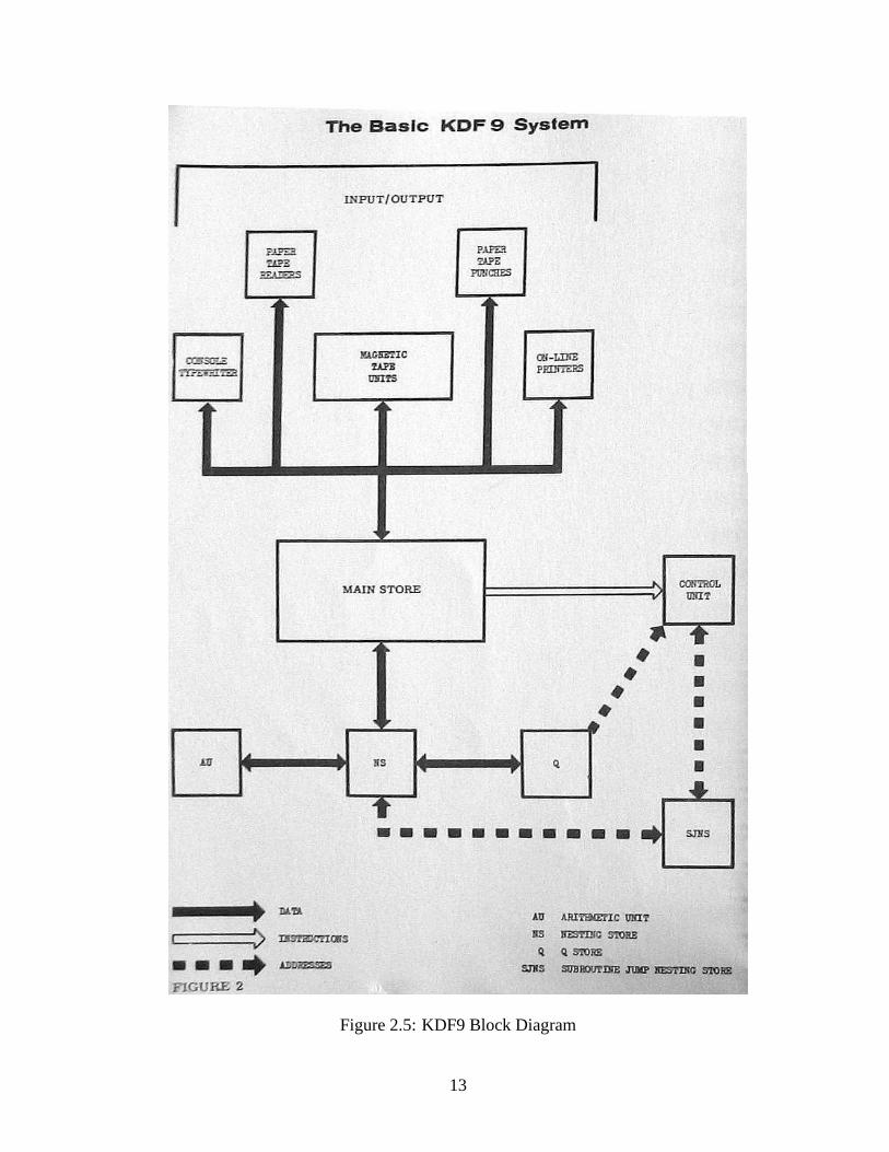
Figure 2.5: KDF9 Block Diagram
13

2.2.3 Burroughs B5000 and later models
The B5000 spawned an entire series of stack computers, all aimed at the direct and efficientexecution of the ALGOL language. They were complex multiprocessing systems with taggedmemory and descriptors for primitive data types and automatic management of subroutineparameters. I will concentrate here on the design and use of the single, in-memory stack thatgoverned the execution of a program. This feature is essentially unchanged across the entireseries.
Figure 2.6 shows the implementation of the stack in the B6900[Bur81, Sec.3]. The stackmemory area is delimited by the contents of the Bottom Of Stack (BOS) and Limit Of Stack(LOS) registers. The current subroutine area is indicated by the F register which points toa Mark Stack Control Word (MSCW). This word contains the context information necessaryto return to the subroutine’s caller. The topmost stack element in use is pointed to by the Sregister.
The A and B registers are a working cache for the top of the stack and are connected tothe ALU. They are extended by the X and Y registers for double-precision calculations. Theircontents are loaded and unloaded as required by each operation in progress and so their entireoperation is transparent to the program. They are not part ofthe stack proper since they areflushed whenever the top of the stack is altered by some operation, such as a subroutine call,and so cannot be used to pass parameters.
The B7700 added a 32-entry circular stack buffer between main memory and the A and Bregisters (Figure 2.7) [Bur73, Sec.2]. This is a genuine buffer that is transparent to the program,and is only flushed if the processor registers (including theS, F, LOSR, and BOSR registers)are altered with a SPRR (Set Processor Register) or a MVST (Move To Stack) operation, orin the case of an atomic memory exchange with the top of the stack using RDLK (Read WithLock).
Both computation and subroutine linkage were done on the same stack in a manner specif-ically designed to support the structure of the ALGOL programming language. When a sub-routine or nested block of code was to be entered, a MSCW was placed on the stack, followedby the parameters to the subroutine, followed by a Return Control Word (RCW) which savedthe condition flags, amongst other things. The local variables and temporary values were thenallocated above all this. Only at this point could the Enter (ENTR) operator be executed toenter the subroutine.
In 1986, the Burroughs Corporation merged with the Sperry Corporation into the UnisysCorporation [Ros87]. The B5000 series of computers continues in the company’s ClearPathline of mainframes.
14
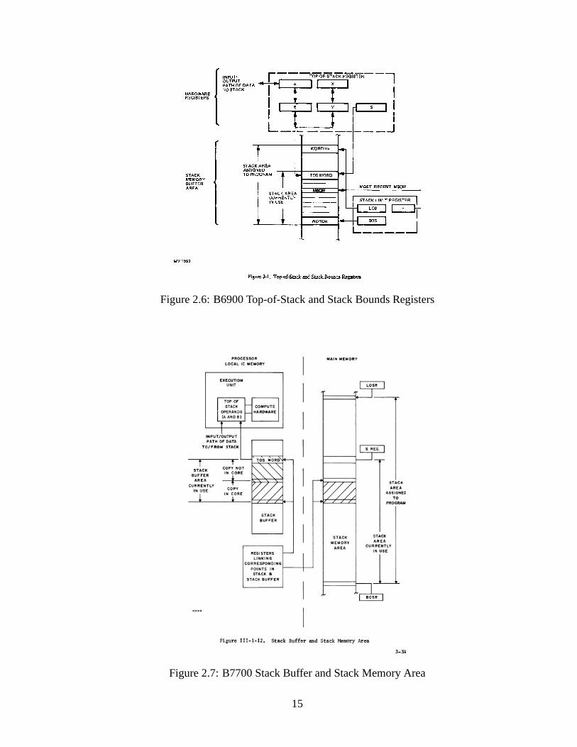
Figure 2.6: B6900 Top-of-Stack and Stack Bounds Registers
Figure 2.7: B7700 Stack Buffer and Stack Memory Area
15
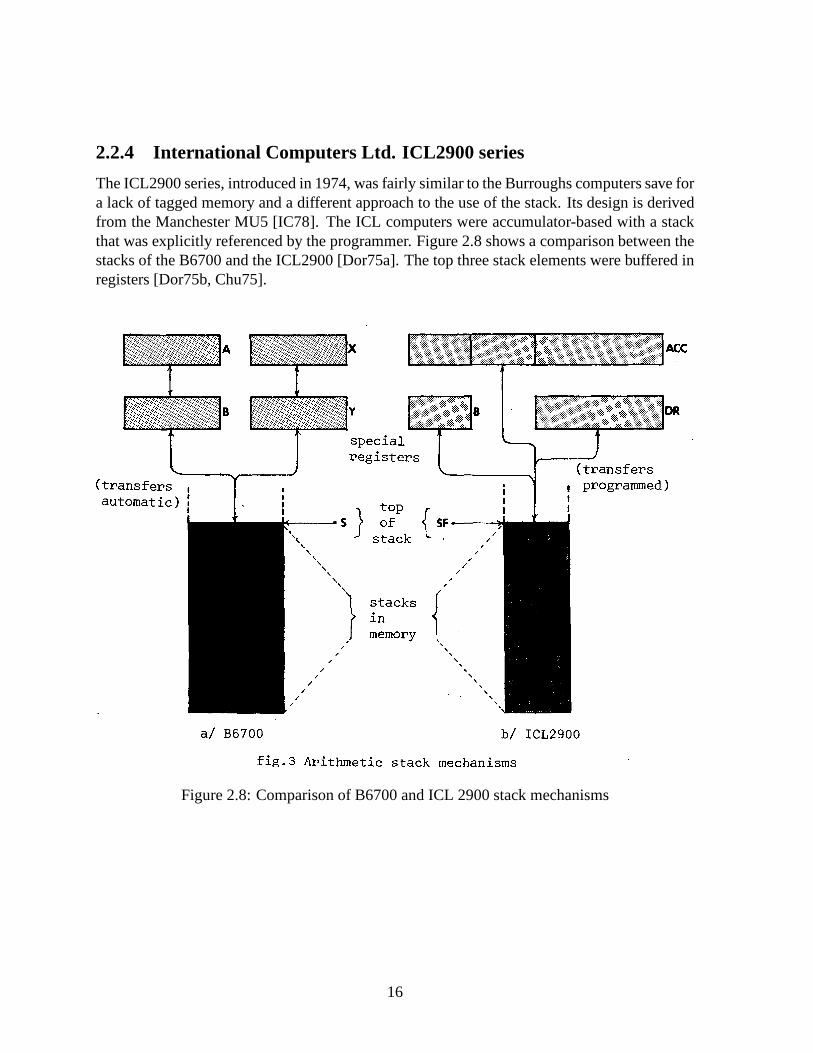
2.2.4 International Computers Ltd. ICL2900 series
The ICL2900 series, introduced in 1974, was fairly similar to the Burroughs computers save fora lack of tagged memory and a different approach to the use of the stack. Its design is derivedfrom the Manchester MU5 [IC78]. The ICL computers were accumulator-based with a stackthat was explicitly referenced by the programmer. Figure 2.8 shows a comparison between thestacks of the B6700 and the ICL2900 [Dor75a]. The top three stack elements were buffered inregisters [Dor75b, Chu75].
Figure 2.8: Comparison of B6700 and ICL 2900 stack mechanisms
16
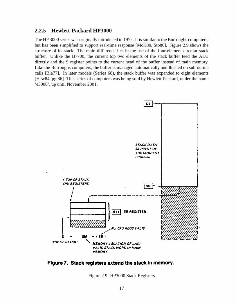
2.2.5 Hewlett-Packard HP3000
The HP 3000 series was originally introduced in 1972. It is similar to the Burroughs computers,but has been simplified to support real-time response [McK80, Sto80]. Figure 2.9 shows thestructure of its stack. The main difference lies in the use ofthe four-element circular stackbuffer. Unlike the B7700, the current top two elements of thestack buffer feed the ALUdirectly and the S register points to the current head of the buffer instead of main memory.Like the Burroughs computers, the buffer is managed automatically and flushed on subroutinecalls [Bla77]. In later models (Series 68), the stack bufferwas expanded to eight elements[Hew84, pg.86]. This series of computers was being sold by Hewlett-Packard, under the name’e3000’, up until November 2001.
Figure 2.9: HP3000 Stack Registers
17

2.3 Shortcomings and Disappearance of the First Genera-tion
During their heyday of about 20 years, stack computers were quite possibly the most sophis-ticated general-purpose computers available. But in retrospect, they had several glaring short-comings which were endemic in machines of the time.
2.3.1 Explicit High-Level Language Support
The idea of directly supporting a high-level language in hardware seems downright baroquetoday. In hindsight however, there were some constraints then that have since vanished:
• Compilers were primitive, and took up a lot of the available memory.
• The machines were slow, leading to long compilation times, only to end up with sub-optimal code!
• Since code was written mostly by hand, and programs were getting larger and harder towrite (including compilers), supporting a high-level language helped the programmer.
These led to two major features: hardware support for the execution models of structuredlanguages such as ALGOL, and the integration of complex functions in the instruction set,implemented as microcode, making it easier to program the computer directly.
These features became weaknesses over time. A computer designed to execute one lan-guage well would perform poorly with another [Org73, ch.8].As compilers improved theygenerated simpler subroutine linkages that did not match the full-featured built-in ones [HP02,2.14]. The compilers also could not use the complex instructions provided. Finally, the mi-crocode for these computers had itself grown to the point of unmanageability [Pat85] (reprinted[Pat86, FL86]).
Eventually, compilers became able to effectively reduce high-level languages features intoseries of simple operations, and the RISC computers that followed were designed in that light.
2.3.2 The Rise of RISC
The first generation of stack computers began to fade away in the early 1980’s with the ad-vent of the Reduced Instruction Set Computer (RISC) designs. The combination of advancesin compilers, hardware speed, and integration forced a revision of the approaches used to im-prove the performance and reduce the costs of the hardware and the software. The combinedend-results flatly outperformed the first generation of stack computers while also efficientlysupporting high-level languages.
18

• Ditzel and Patterson criticized the original arguments forHigh-Level Language Com-puter Systems (HLLCS) [DP80] (reprinted [DP86, FL86], and [DP98b] with updatedcomments [DP98a]), and conclude that “. . . almost any system can be a HLLCS throughthe appropriate software. . . ”. They also wrote an overview of the arguments for reducedinstruction sets [PD80].
• Patterson later wrote an extremely broad article on the features and successes of the earlyRISC experiments, including software measurements and compiler techniques [Pat85](reprinted [Pat86, FL86]), and advocates taking implementation as a factor in computerarchitecture.
• At Berkeley, Patterson and Sequin headed the RISC I and RISC II projects as one ap-proach to RISC designs [PS81] (reprinted [PS98a] with updated comments [PS98b]).The fine details of their implementation were presented in the PhD thesis of one of theirstudents, Manolis Katevenis [Kat85].
• One of the premises of RISC design is that the hardware and thesoftware must be con-sidered together. Hennessy and Jouppi measured the low-level features of software andproposed some architectural guidelines to support them without the pitfalls of past high-level language support. These included “. . .the use load/store architecture and the ab-sence of condition codes. . . ”. [HJB+82]. These data guided the Stanford MIPS project[HJP+82].
• The major technological change of the time was the emergenceof Very Large Scale In-tegrated (VLSI) circuits which made possible the implementation of an entire processoron a single chip. The various approaches to integrated architecture are discussed byHennessy [Hen84] (reprinted [Hen86, FL86]).
2.3.3 Excessive Memory Traffic
Without an optimizing compiler, a requirement for the explicit support of a structured, high-level language was the use of an execution stack in main memory instead of registers in theprocessor. This increased traffic to main memory, which was much slower, and further drovethe development of complex microcoded instructions to avoid accessing it.
For example, passing parameters to a subroutine required copying values from a locationin the caller’s stack frame to one in the callee’s frame, necessitating a memory read and a writefor each parameter. Local variables and temporary values were also on the stack since therewas no location in the processor to store them, further increasing memory traffic. In the caseof the Burroughs computers, the use of a single stack meant that subroutine parameters wereburied under the return address and other subroutine linkage information. This meant that theycould not be used directly for computation without explicitloads into the top of the stack.
In later stack computers, some registers were used to bufferthe top of the stack, but theirsmall number (four or less) limited their usefulness to holding intermediate results of algebraicexpressions. The subroutine linkage conventions requiredthe registers to be flushed whenevera subroutine was called and so they could not be used to pass parameters. The Burroughs
19
B7700 was likely the only first-generation stack computer toaddress this problem by includinga genuine 32-entry buffer (Figure 2.7) for the top of the stack [Bur73, pg.3-36] .
2.3.4 The Need for Index Registers
Stack computers execute iterative code poorly compared to general-purpose register comput-ers. Random-access registers can hold the loop indices and intermediate results for immediateaccess. On the other hand, a stack computer must temporarilymove values off the top of thestack to access any index or result that isn’t the most immediate. It is the source of enormousoverhead whether or not this generates memory traffic and special-purpose index registers haveto be used to reduce it. All first-generation stack computersincluded some form of index reg-ister:
• The KDF9 was the first to do so by including the Q-Stores [Hal62] (Figure 2.4). Theywere abundant (16) and could be also used as general-purposeregisters.
• The B5000 series encoded loop counts in special instructions, such as BEGIN LOOP(BLP), END LOOP (ELP), and JUMP OUT LOOP CONDITIONAL (JLC), which re-used some internal registers to hold addresses while in Character Mode4 [Bur63] [Bur67].
• The B7700 added a vector mode of operations in which the indexfor one loop and theaddresses and increments for up to three arrays were stored in separate internal registersso as to free the stack for computations [Bur73, pg.3-112].
• One of the three top-of-stack registers of the ICL 2900 couldbe used as an index register[Dor75a].
• The HP 3000 series had a single index register (X) to support loops [Hew84].
4Character Mode processed 6-bit Binary-Coded Decimal numbers, while Word Mode processed binary 48-bitnumbers.
20
Chapter 3
History of the Second Generation of StackComputers
In this chapter, I present the second generation of stack computers in the context of the pioneersof the field and of the machines that followed their insights.At the same time that the firstgeneration of stack computers was fading away in the light ofRISC, the second generationbegan to emerge and found a niche in embedded control systemsinstead of general-purposecomputing.
3.1 Charles H. Moore and the Second Generation
The latest wave of second-generation stack computers was almost entirely initiated by CharlesH. Moore and documented by Philip J. Koopman, Jr., with some additional unpublished mate-rial made available online by Jeff Fox [Fox04].
3.1.1 Charles Havice (Chuck) Moore II
Chuck Moore studied physics at MIT (BS, 1960) and mathematics at Princeton. He became afreelance programmer during the 1960s and the software toolkit he created for himself gradu-ally evolved into the Forth programming language [ML70]1. Along with Elizabeth Rather andNed Conklin, he co-founded Forth Inc. in 1973 [RCM93] [RCM96]. In 1981, Moore beganto pursue hardware implementations of the Forth virtual machine. This work was the basis forthe second generation of stack computers and continues to this day.
3.1.1.1 The Forth Programming Language Basis of Second-Generation Stack Comput-ers
Much as stack computers from the first generation were based on ALGOL, those from thesecond generation are derived from the Forth programming language. Surprisingly, there seemsto be no historical connection at all between the design of Forth and the early work of CharlesHamblin (Section 2.1.4) or the design of the KDF9 computer (Section 2.2.2). However, the
1Online as of March 2007 at http://www.ultratechnology.com/4th_1970.pdf and /4th_1970.html
21

Burroughs B5500 computer was the influence for the use of a stack for expression evaluation[Moo91]. The best introduction to Forth and the methodologies it favours are a pair of booksby Leo Brodie [BI86] [Bro84].
A Forth system is divided into two interpreters. The outer interpreter receives source inputand looks up each word in a dictionary. If found, it calls the inner interpreter to process theword’s definition. In the most basic case a word definition is aseries of addresses of otherwords, themselves defined in the same manner, ending with primitives which are written inmachine code2. The inner interpreter is a small virtual machine which walks through thesedefinitions and executes the primitives it encounters. The inner interpreter keeps track of thenesting of these definitions on a stack in memory, commonly referred to as the Return Stack.
The Forth primitives do their operations on another such stack, the Data Stack, where theytake their arguments and place their results. The primitives are thus simple function applica-tions which can be composed by executing them in sequence. Higher-level words are functionalcompositions of these primitives. These new words interactwith the stack and compose in thesame manner as the primitives.
A second-generation stack computer is basically a physicalrealization of the inner inter-preter, the Forth primitives, and the stacks. The primitives become the instruction set whichoperates on a hardware Data Stack. The inner interpreter reduces to simple call and returninstructions which use a Return Stack to store the return addresses of subroutines.
3.1.2 Philip J. Koopman, Jr.
From 1986 to about 1995, Philip J. Koopman, Jr. did the most well-know applied and theo-retical research on stack computers while at WISC Technologies, Harris Semiconductor (nowIntersil), the United Technologies Research Centre, and Carnegie Mellon University (wherehe is now part of the faculty). His book on stack computers is still the single best referenceon the subject [Koo89]. His paper on modern stack computer architecture [Koo90] containsthe essential insights and comparisons to the CISC (ComplexInstruction Set Computer) andRISC (Reduced Instruction Set Computer) designs of the time. He also did the initial work onefficiently compiling the C language to such machines [Koo94]. He touches upon the problemof pipelining a stack computer in a set of slides [Koo91]. Finally, he co-authored some com-parative performance studies [KKC92b] [KKC92a]. Althoughhe has left stack computers as aresearch field, his academic work remains the most visible one known.
2This is known as ’indirect-threaded code’. There exists also direct-threaded, string-threaded, token-threaded,and subroutine-threaded versions, each with different size/speed trade-offs. Second-generation stack computersare subroutine-threaded systems.
22

3.2 The Second Generation of Stack Computers
I’m concentrating here on the computers primarily designedby Chuck Moore. There are manymore machines than the ones listed here (see Koopman’s book [Koo89, App.A]), but Moore’swork was by far the most ground-breaking and influential. Much less was published about hismachines than those of the first generation. Therefore, the descriptions here are mostly basedon information found in Koopman’s book, reference manuals,and unpublished documentation.
3.2.1 NOVIX NC4016
Formed in 1983, NOVIX produced the first prototypes of the NC4016 (initially called theNC4000) in 1985. The NC4016 was a 16-bit processor, designedby Chuck Moore, which ranthe Forth programming language natively. It was a remarkably small device implemented inabout 4000 gates, amounting to about 16000 transistors [Mur86] [Koo89, 4.4]. Figure 3.1ashows a block diagram [Koo89, fig.4.6].
Since the NC4016 was a hardware realization of the Forth programming language, it sup-ported an expression evaluation stack and a subroutine linkage stack both separate from mainmemory and accessed via separate external buses. It also used an unencoded instruction for-mat, similar to microcode, which allowed simultaneous control of the ALU, the stacks, and thememory. A clever compiler could combine two to five primitiveForth operations into a singleinstruction. In ideal conditions, the NC4016 could manipulate both stacks, fetch from mainmemory, execute an ALU operation, and perform a subroutine return all in the same cycle.
The NC4016 led to the NC6016, which was licenced to Harris Semiconductors in 1987 andrenamed the RTX-2000 [RCM96]. NOVIX ceased operations by 1989.
3.2.2 Harris3 RTX-2000
The RTX-2000 is derived from the NC4016. The the main changesinclude the addition ofbyte-swapped memory access, some counter/timers, an interrupt controller, and a hardware16x16 multiplier. The stacks are now on-chip [Koo89, 4.5] and can be subdivided into smallerstacks to support fast task switching. The RTX-2000 has mainly seen application in aerospacesystems. Versions of the processor manufactured in radiation-resistant (’rad-hard’) processes[Int00] have flown (and are still flying) on several NASA missions [Fre98] [Fre01] [Ras03].Figure 3.1b shows a block diagram [Koo89, fig.4.8].
3.2.3 Sh-BOOM (Patriot Scientific IGNITE I)
In 1988, Russell Fish proposed a new low-cost microprocessor targeted at embedded systems,the Sh-BOOM, which Chuck Moore designed. It contained a 32-bit dual-stack microprocessorwhich shared the single DRAM memory bus with a smaller dedicated processor for deter-ministic transfers to peripherals and for dynamic memory refresh. The stacks, for expressionevaluation and subroutine linkage, were on-chip, about 16 cells deep each, and would spill/fill
3Now Intersil.
23

to/from memory as required. The implementation used about 9000 gates. Figure 3.2 shows ablock diagram of the main processor [Sha02, fig.1].
Contrary to the NC4016 or the RTX-2000 the Sh-BOOM did not usean unencoded instruc-tion format, but packed four 8-bit, Forth-like instructions into each memory word. This formeda simple instruction cache that allowed instructions to be executed while the next memory fetchwas in progress. This also allowed very small loops to execute from within the cache withoutrequiring an instruction fetch. Another interesting feature was the use of conditional SKIPinstructions which, if the condition was met, would skip over the remainder of the instructionsin the memory word. Conditional jumps and calls were implemented this way [GWS91].
The Sh-BOOM broke away from a pure stack architecture by including 16 general-purposeregisters (g0-g15), and by making most of the on-chip returnstack addressable as registers (r0,r1, etc. . . ). The general-purpose registers were used for temporary storage and for I/O opera-tions, much like the KDF9. To support the stack frames of ALGOL-like languages, instead ofsimply pushing values on the return stack, a number of empty locations could be allocated inone step and then later filled from the general-purpose registers.
The Sh-BOOM design is currently being marketed by Patriot Scientific4 as the IGNITE I[Sha02] (previously PSC1000 [Sha99]) processor core, targeted at embedded Java applications.It is the most sophisticated second-generation stack computer currently available.
(a) NC4016 (b) RTX-2000
Figure 3.1: NC4016 and RTX-2000 Block Diagrams
4http://www.ptsc.com/
24

Figure 3.2: IGNITE I Block Diagram
3.2.4 MuP21
First published in 1995 [MT95], the MuP21 was the first of a family of chips dubbed MinimalInstruction Set Computers (MISC). Like the Sh-BOOM, it useda packed instruction formatwhich held four 5-bit instructions in a 20-bit memory word. The internal stacks and ALU were21-bits wide to support arithmetic carry. The data stack wasonly six cells deep, and the returnstack was a mere 4 cells deep. An address register (A) was added for temporary storage andfor memory accesses.
Like the Sh-Boom, the MuP21 also contained a small auxiliaryprocessor which had pri-ority access to the memory bus. However, it was a video processor which executed its owninstruction set, also 5-bits wide, which was tailored for creating a 16-colour NTSC signal at anoutput pin. A frame of video was described by a block of these instructions which could bemanipulated by the main processor.
Amazingly, the entire implementation used only 7000transistors in a 1.2u process, had atypical speed of 80 MIPS, and dissipated only 50 mW. There arehints that the design wasfully asynchronous. The MuP21 was an influential design. Itssimplicity made it an idealchoice for undergraduate and hobbyist projects, usually asFPGA implementations (for exam-ple: [HH00]).
25

3.2.5 F21
Jeff Fox had formed UltraTechnology in 1990 in Berkeley, to develop a custom computer incollaboration with Chuck Moore. The result was the F21 microprocessor [Fox98], which wasan extension of the MuP21. The instruction set added post-incrementing loads and stores fromthe address register and the top of the return stack, and someextra arithmetic operations. Thestacks were expanded to about 17 cells each. Like the MuP21, the memory interface was20-bits wide and values were stored internally as 21 bits.
Like the MuP21, the F21 contained a video coprocessor, and added similar coprocessorsfor analog I/O and serial networks. Some common routines were included in on-chip ROM.
In a 0.8u process, the F21 was implemented in about 15,000 transistors, and had a typicalexecution rate of 100 MIPS (peaking internally at 500 MIPS),depending on memory accesstime. Ultratechnology ceased to exist in 2002 with nothing formally published about the designand only some prototype chips made. The website for the company5 contains some fairlydetailed documentation. For a reconstruction of what the block-level design might have beenlike, see Figure 6.1.
3.2.6 c18
Around 2001, Moore took the F21 design in a new direction and produced the c18 [Moo01b,Moo01a]. Architecturally, it is virtually identical to theF21, but adds a second address registerfor on-chip communication. Its width was also reduced to 18 bits to match the fast cachememory chips available at the time. This leaves room to pack only 3 instructions per memoryword.
The coprocessors were eliminated and replaced by a watchdogtimer. There is no externalmemory bus. External memory must be accessed via the parallel I/O pins, and programs mustbe loaded into a few hundred words of on-chip RAM to be executed.
The c18 was simulated in a modern 1.8V 0.18u process. It had a predicted *sustained*execution rate of 2400 MIPS, while dissipating about 20 mW. It was an aggressive, fully asyn-chronous design.
The c18 was targeted at multiprocessing. A 5x5 array of c18’s, connected by horizontaland vertical buses, would fit in 7mm^sq. This eventually became realized as the SEAforth-24multiprocessor currently entering production at Intellasys6 (Intelligent Array Systems) .
3.3 Recent Research
Most of the research in the last decade has been outside of academia, and/or of little visibilitydue to the mistaken lumping of these second-generation designs with the previous generation.This section will overview the most salient academic, commercial, and amateur research onthe subject.
• Between 1994 and 2004, Christopher Bailey co-authored a number of papers on vari-ous enhancements to stack computers for High-Level Language support, interrupt per-
5As of March 2007: http://www.ultratechnology.com/f21.html6http://intellasys.net/
26

formance, and instruction-level parallelism [Bai94] [BS94] [Bai00, DBL00] [Bai04][SB04]. His 1996 PhD thesis presented an improvement to stack spill/fill algorithmsso as to further reduce memory traffic [Bai96].
• During his Master’s studies at the University of Alberta, Robert James Chapman ex-plored the synthesis of stack computers using VHDL [Cha97] [Cha98] and wrote a pa-per which decomposed the usual stack permutation operations into smaller primitives[Cha95].
• Myron Plichota is a freelance consultant in Hamilton, Ontario who designed in 2001the Steamer 16 processor7 as a VHDL design implemented on a Cypress CY37128P84-125JC CPLD (Complex Programmable Logic Device). It is notable for fitting in verylittle hardware, having only eight, 3-bit instructions, and a bare minimum 3-deep on-chip stack. It runs Forth-like software with C-like stack frames in main memory. It isremarkable in its speed/size trade-off while still achieving 20 MIPS. It has been used inan industrial machine vision application.
• While at the Technical University of Munich, Bernd Paysan wrote his 1996 Diploma the-sis on the 4stack processor8 [Pay96], a 4-way superscalar VLIW (Very Long InstructionWord) design specified in Verilog. It is meant for embedded DSP (Digital Signal Pro-cessing) applications, but has a supervisor mode and virtual memory for desktop use. Healso designed the much smaller b16 microprocessor9 [Pay02], a 12-bit version of whichis used internally at Mikron AG.
• Chung Kwong Yuen10 at the National University of Singapore has an unpublished paper[Yue] on how to implement a reorder buffer to obtain superscalar execution in stackcomputers11.
• Chen-Hanson Ting currently runs the eForth Academy12 in Taiwan, which provides de-sign classes for embedded systems. He created the P series ofmicroprocessors13 derivedfrom the works of Chuck Moore. They are described in [Tin97a,Tin97b]1415.
• A number of students at the Chinese University of Hong Kong designed and imple-mented two versions of a derivative of the MuP21 microprocessor : The MSL16 wasfirst implemented on an FPGA (Field-Programmable Gate Array) [LTL98] and later re-implemented in silicon using asynchronous logic as the MSL16A [TCCLL99].
7The only documentation was at http://www.stringtuner.com/myron.plichota/steamer1.htm which is now de-funct, but archived in the Internet Archive Wayback Machineat http://www.archive.org/web/web.php
8http://www.jwdt.com/~paysan/4stack.html9http://www.jwdt.com/~paysan/b16.html
10http://www.comp.nus.edu.sg/~yuenck/11One of two papers available at http://www.comp.nus.edu.sg/~yuenck/stack12http://www.eforth.com.tw/13http://www.eforth.com.tw/academy-n/Chips.htm14Publication list: http://www.eforth.com.tw/academy-n/Bookstore/bookstore_4.htm15Published by Offete Enterprises: http://www.ultratechnology.com/offete.html
27

3.4 Strengths and Weaknesses of the Second Generation
The second generation of stack computers still has some of the drawbacks of the first: a needfor index registers, stack manipulation overhead, and it additionally supports ALGOL-like lan-guages poorly. However, the second generation also has somedistinct advantages: reducedmemory bandwidth and system complexity, and faster subroutine linkage and interrupt re-sponse.
3.4.1 The Need for Index Registers
As in computers from the first generation (Section 2.3.4), the access of loop indices or interme-diate results which are not immediately on top of the stack requires significant stack manipula-tion overhead. All second-generation stack computers, except the very smallest, mitigate thisproblem with index registers:
• The NC4016 buffered the topmost Return Stack element on-chip so it could be used as anindex register (I). A loop-on-index instruction would decrement I, and then conditionallyjump to the beginning of the loop. The RTX-2000 used the same mechanism.
• The Sh-Boom used a count (ct) and an index (x) register. The count register was usedby decrement-and-branch-on-non-zero instructions, and the index register was used fordirect, post-incrementing, and pre-decrementing memory accesses.
• The MuP21 used the A register to hold memory addresses which could then be moved tothe data stack, modified, and the returned to A for the next access. The alternative wouldhave needed a deeper stack and more stack manipulation opcodes.
• The F21 could do post-incrementing memory accesses from A register and from the topof the Return Stack. They were primarily meant for fast memory-to-memory transfers.The c18 has the same mechanism.
3.4.2 Stack Manipulation Overhead
Stack computers from the first generation suffered from excessive memory traffic (Section2.3.3) since their stacks, except for a few working registers, were entirely in main memory.However, this had the advantage of allowing random access tothe entire stack.
Computers from the second generation keep their stacks separate from main memory andusually on-chip. This has the advantage of causing no memorytraffic, but typically limitsaccess to the topmost two to four elements since the stack is no longer addressable. Thislimitation requires that the topmost elements be permuted to bring a value to the top of thestack (Section 7.3.3).
The original overhead of memory traffic is thus transformed into the overhead of extraoperations to manipulate the stack. This problem can be mitigated by using more deeply-accessible stacks or more complex stack manipulation operations. This random access comesat the price of increased system complexity, culminating ina conventional multiparty registerfile.
28

3.4.3 Poor Support of ALGOL-like Languages
Languages which are derived from ALGOL, such as C, use the stack as a means of allocatingspace for, amongst others, the local variables of a procedure. This entails pushing entire struc-tures onto the stack and then accessing them randomly, oftenthrough a pointer. Thus a localvariable must be present in main memory since the stack in a second-generation computer isnot addressable.
Solutions to this problem include more sophisticated compilers [Koo94] [ME97] [ME98],the addition of some form of frame pointer register which cansupport indexed addressing, ormaking the return stack addressable such as in the PSC1000/IGNITE I [Sha02] [Sha99].
3.4.4 Reduced Instruction Memory Bandwidth and System Complexity
The compact encoding of stack instructions stems from the implicit nature of their operands:It is always the top of the stack. Thus, contrary to a registermachine, several such operationscan fit into a single memory word. This correspondingly reduces the frequency of instructionfetches. The memory access cycles between instruction fetches can then be used for loads,stores, and fetches, eliminating the need for separate instruction and data memory buses (Sec-tion 7.2.4). This greatly reduces system complexity and allows for a higher internal operatingfrequency than the memory would normally allows.
The case of unencoded instructions, as in the NC4016 and the RTX-2000, does not providethe same memory bandwidth advantage, but while still operating on a single memory bus,increases the performance through the multiple simultaneous operations that can be containedin such an instruction word.
3.4.5 Fast Subroutine Linkage and Interrupt Response
A stack computer does not need to save the contents of registers upon entering a subroutine. Itsparameters are already on top of the data stack, which becomeits working values throughoutthe computation, and ultimately remain as one or more returnvalues upon exiting the subrou-tine. The call and return instructions automatically use the return stack for the return address.Subroutine linkage thus requires no additional memory traffic and takes only a cycle or two(Section 7.3.6).
An interrupt service routine (ISR) is effectively a hardware-invoked subroutine, and sobenefits from the fast linkage. The ISR can simply do its work on top of the stacks so long asit leaves them unaltered upon exit.
29

30

Part II
Qualitative Arguments
31

Chapter 4
Distinguishing the First and SecondGenerations
The existing computer architecture literature considers all stack computers to be of the samekind1. This view seems correct when contrasted against modern register-based machines. How-ever, it conflates the first and second generations of stack computers, which makes difficult aclear discussion of their respective properties. Distinguishing the generations is important sincethe second resembles current register-based designs much more than it does the first. Withoutthis distinction, an entire branch of computer architecture is missed solely due to a categoricalerror.
The differences between the generations stem from the two historical approaches to stackcomputation. The first generation is based on Bauer’s “stackprinciple” for subroutine storageallocation (Section 2.1.3) and is exemplified by the Burroughs B5000 series (Section 2.2.3).The second generation originates in Hamblin’s method for evaluating and composing expres-sions (Section 2.1.4), first seen in the English Electric KDF9 (Section 2.2.2), and later inde-pendently rediscovered as the Forth programming language (Section 3.1.1.1).
The only significant exception to this conflation I’ve found is a section in Feldman andRetter’s text [FR93, pp.599-604] which lists some of the same “first generation stack machines”as I do in Section 2.2, then proceeds to explain in a nutshell the origin and features of the secondgeneration of stack computers, although they do not refer tothem by that name.
In this chapter, I expand on Feldman and Retter’s statementsand propose a codificationbased on some properties of the stacks: their location, purpose, and the operations done uponthem.
1Except for a passing mention in the preface of Koopman’s book[Koo89] and a short summary in Bailey’sPhD Thesis [Bai96].
33

4.1 Location of Stacks: In-Memory vs. In-Processor
“[. . . ] It is this explicit coupling of all ALU operations to ahardware stack whichsets these machines apart.”
[FR93, pg.600]
The first distinguishing feature is the location of the stacks.First-generation stack computers (Figure 4.1) kept their stacks as randomly accessible data
structures in main memory, located by an automatically managed stack pointer register. Eachoperation implicitly loaded and stored the required data for expression evaluation to an internalstack of two to four registers. The number and size of the stacks in memory were variableand usually each process had its own. Later machines used circular buffers between the reg-isters and the memory to accelerate access to items recentlyput on the stack. Unfortunately,first-generation stack computers were overtaken by register-based machines before this featurebecame widespread.
General-purpose register computers (Figure 4.2) use the same kinds of stacks, also keptin memory. However, the stack pointer is now an ordinary register, selected by convention,and is manually controlled by software. Software manually loads and stores values from thestack into an arbitrarily accessible register file. Register machines usually place a cache bufferbetween the registers and memory.
Contrary to both first-generation and general-purpose register computers, second-generationmachines (Figure 4.3) keep their stacks in the processor. The stacks are not randomly accessi-ble data structures and only make visible the top two to four elements. The stacks are separatefrom main memory and only interact with it via load, store, and flow control instructions. Thenumber and size of the stacks are fixed, although they may spill to memory via a pointer, de-pending on the size of the system, and thus behave as their owncaches. There are typically onlytwo stacks, shared by all processes, which can internally exchange data amongst themselves.
Return AddressParameters of A
Return Value from A
Locals of AReturn Value from B
Parameters of BReturn Address
Locals of B
Memory
Stack Pointer
Stack
CPU
Figure 4.1: First-Generation Stack ComputerBlock Diagram
Return AddressParameters of A
Return Value from A
Locals of AReturn Value from B
Parameters of BReturn Address
Locals of B
CPU MemoryRegisters
Figure 4.2: General-Purpose Register Com-puter Block Diagram
34

4.2 Use of Stacks: Procedure Nesting vs. Expression Evalu-ation
“[. . . ] While recursion is easy to accomplish with a stack in memory, this is notwhat we mean bystack machine. [. . . ]”
“[. . . ] Unlike most earlier stack machines, these Forth processors have two stacks,one to hold temporary data and pass subroutine parameters, and the other to savesubroutine return addresses and loop counters. [. . . ]”
[FR93, pg.600]
The second distinguishing feature is the use of the stacks.First-generation stack computers (Figure 4.1) used stacksas structured temporary storage
for program procedures. Each procedure invocation would automatically cause the allocationof an amount of space on the stack to contain (typically) the parameters of the procedure, itsreturn value, its local variables, and the return address ofits caller. This area is referred-to asa procedure activation record. Values from the record were loaded and stored into the smallinternal stack as needed for expression evaluation. The internal stack only held the intermediateresults of computations within a given procedure. All linkage between procedures was donesolely on the stack in memory.
General-purpose register computers (Figure 4.2) use the same kind of stacks, in the samemanner, except that the procedure activation records are manually managed by software andprocedure linkage can occur through the registers if the parameters, locals, and return valuesfit within them.
Second-generation stack computers (Figure 4.3) use separate stacks to control procedurenesting and to perform expression evaluation. The return addresses of procedure calls arestored on a stack dedicated to that purpose (Return Stack). Storing them separately helps toeliminate the division of the other stack (Data Stack) into procedure activation records. Thus,a called procedure finds its parameters (P) on top of the Data Stack, manipulates them directlyas locals (L) during expression evaluation, and leaves on top either its return value (R) uponexit or the parameters for calling another procedure. The Data Stack is used for an effectivelysingle, large, and complex expression evaluation whose parts are tracked by the contents of theReturn Stack.
Return AddressReturn Address
CPU
Memory
L/P/R of B
L/P/R of AL/P/R of AL/P/R of A
L/P/R of BL/P/R of B
Data Stack Return Stack
Figure 4.3: Second-Generation Stack Computer Block Diagram
35

4.3 Operations with Stacks: High-Level Language Supportvs. Primitive Operations
“First generation stack machines, such as the Burroughs B5000, B5500, B6700,B7700, Hewlett-Packard HP3000, and ICL2900, were designedto execute lan-guages like Algol-60 [Dor75b]. Most of these had a single stack which was usedfor holding temporary data, passing subroutine parameters, and saving subroutineaddresses. [. . . ]”
[FR93, pg.600]
The third distinguishing feature is the operations performed upon the stacks.First-generation stack computers (Figure 4.1) had built-in hardware and microcode support
for high-level language (typically ALGOL) and operating system features. The procedure calland return instructions would automatically allocate and deallocate activation records on thestack. The arithmetic instructions would determine the data type of their operands from specialtags. Indirect reference words and data descriptors would allow for lexical scoping across ac-tivation records and resolve call-by-name references. Multiple stacks could be maintained andcross-referenced to enable multitasking and inter-process communication. Descriptors couldpoint to data on disk to support code and data paging-on-demand. The end result was powerful,but extremely complex. These features are well-described in Organick’s book [Org73].
General-purpose register computers (Figure 4.2) have noneof these language-specific fea-tures, although they were designed with the efficient support of ALGOL-like languages inmind. A large register file supports fast, simple procedure linkage when possible, and can holdmultiple intermediate values during expression evaluation. The instruction set is simple but canuse any registers as source and target. High-level languageand system features are managedin software by the compiler and the operating system.
Second-generation stack computers (Figure 4.3) have more in common with general-purposeregister machines than with first-generation stack computers. The call and return instructionsonly save and restore the calling procedure’s return address, leaving more complex procedurelinkage to software. Arithmetic instructions operate solely on the top few elements of an inter-nal stack and their operands must be loaded from and stored tomemory explicitly. Only simpledirect and indirect addressing modes are supported, although post-incrementing/decrementingversions are common. Other than the implicit use of stacks for basic procedure linkage andexpression evaluation, all high-level language and operating system features are implementedin software in the same manner as in register-based machines.
36

Chapter 5
Objections Cited by Hennessy & Patterson
Hennessy and Patterson’s magnum opus “Computer Architecture: A Quantitative Approach”[PH90, HP96, HP02] has a tremendous influence on the field of computer architecture. I sup-port this claim by comparing the number of citations it has received compared to other text-books on computer architecture.
Most arguments against stack computer architecture are drawn from a few statements foundin this book. I present counterarguments which support the claim that the statements are validfor the first generation of stack computers, but not the second.
5.1 The Enormous Influence of Hennessy & Patterson onComputer Architecture
Some data collected in Fall 2004 provides a view of this excellent book’s status (Table 5.1)based on the number of citations it has received compared with that of other books on computerarchitecture. These books were all found in the University of Waterloo Davis Centre Library.The number of citations was obtained from the ACM Digital Portal’s Guide To ComputingLiterature1.
It’s easy to see that the influence of the first two editions of Hennessy & Patterson’s workcompletely dwarfs that of the remainder of the sample. As of January 2006, the updated cumu-lative number of citations provided by the ACM Guide are:
• First Edition [PH90]: 424
• Second Edition [HP96]: 454
• Third Edition [HP02]: 125
Additionally, the CiteSeer2 scientific literature library show a total of 1525 citationsfor alleditions combined, as of January 2006.
1http://portal.acm.org/2http://citeseer.ist.psu.edu/
37

Incidentally, the main text on second-generation stack computers [Koo89] had, accordingto the ACM Guide, seven citations in the Fall of 2004 and twelve as of January 2006. It is notlisted in CiteSeer.
Book Citations Book Citations
[PH90] 324 [FR93] 1[HP96] 310 [MK97] 1[HP02] 19 [HVZ95] 0[PH98] 21 [Sta02] 0
[Hwa92] 50 [GL03] 0[Kog90] 24 [Omo99] 0[Omo94] 6 [Bur98] 0[SSK97] 6 [Sto92] 0[Sta93] 2 [Wil91] 0[Wil01] 1 [Sta90] 0[Hay97] 1 [Mur90] 0[Wil96] 1 [Bla90] 0[MP95] 1
Table 5.1: Comparison of Citations of Computer Architecture Texts (as of Fall 2004)
5.2 The Disappearance of Stack Computers (of the First Gen-eration)
One of the views expressed by Hennessy & Patterson is that “stack based machines fell out offavor in the late 1970s and, except for the Intel 80x86 floating-point architecture, essentiallydisappeared.” [HP96, pg. 113][HP02, pg. 149]. This statement can only refer to the first gen-eration of stack computers since the second generation did not really begin until 1985 (Section3.2.1), “roughly concurrent with the emergence of RISC as a design philosophy” [FR93, pg.600].
These new machines went unnoticed due to being in the niches of embedded real-timecontrol and aerospace applications (Section 3.2.2) instead of general-purpose computing. Thelatter instances of the second generation were developed inthe 1990s, with little visibility inacademia (Section 3.3), since by then the term ’stack computer’ had become synonymous withdesigns from the first generation.
38

5.3 Expression Evaluation on a Stack3
Hennessy & Patterson state:
Although most early machines used stack or accumulator-style architectures, vir-tually every machine designed after 1980 uses a load-store register architecture.The major reason for the emergence of general-purpose register (GPR) machinesare twofold. First, registers—like other forms of storage internal to the CPU—arefaster than memory. Second, registers are easier for a compiler to use and can beused more effectively than other forms of internal storage.For example, on a reg-ister machine the expression(A ⋆ B) − (C ⋆ D) − (E ⋆ F ) may be evaluated bydoing the multiplications in any order, which may be more efficient because of thelocation of the operands or because of pipelining concerns (see Chapter 3). Buton a stack machine the expression must be evaluated left to right, unless specialoperations or swaps of stack positions are done. [HP96, pg. 71]
The third edition has a different final sentence:
Nevertheless, on a stack computer the hardware must evaluate the expression inonly one order, since operands are hidden on the stack, and itmay have to load anoperand multiple times. [HP02, pg. 93]
The first point, which implies that the stack is in memory, is no longer valid. Second-generationstack computers keep their stacks internal to the CPU (Section 4.1). Furthermore, the accessto a stack is faster than to registers since no addressing is required. The inputs to the ALU arehardwired to the top two elements of the stack. This is put to advantageous use when pipelining(Section 7.4).
Secondly, the claim that compilers can use registers more effectively is true only becausemuch research has been done on register allocation in moderncompilers. Prior to the adventof modern compiler techniques like graph colouring, registers were seen as difficult to useand stacks were favoured. For example, this is the reason theSPARC architecture uses reg-ister windows which effectively form a stack of activation records [PS98a, pg. 2]. There hasbeen promising work showing that it is possible to cache virtually all local variable memoryreferences onto the stack [Koo94]4[ME97]5[ME98]6. Also, it could be possible to evaluateexpressions in an out-of-order fashion on a stack computer (Section 3.3).
Lastly, the final point raised is true. Operands are hidden onthe stack and even with theaforementioned compiler techniques this fact makes for poor performance on iterative codedue to the stack manipulations required (Section 7.3.3). However, a register-based computerhas the same kind of repeated memory accesses and register-to-register copying overhead when
3The arguments in this section suggest an interesting way of thinking qualitatively about stacks: that theyare the ’reciprocal’ (or the ’inverse’) of registers. For example, reading a register does not destroy its contents,but writing does. Conversely, reading from a stack pops information from it, but writing to it simply pushes theexisting information down. Up to its maximum capacity, no information is lost. This is a tantalizing symmetry.
4http://www.ece.cmu.edu/~koopman/stack_compiler/index.html5http://www.complang.tuwien.ac.at/papers/maierhofer%26ertl97.ps.gz6http://www.complang.tuwien.ac.at/papers/maierhofer%26ertl98.ps.gz
39

entering or exiting a subroutine (Section 7.3.6). This overhead is virtually nil in stack comput-ers . Finally, there are hints that a redesigned stack computer instruction set could combinestack manipulations with arithmetic operations ’for free’, without adding any new datapath orcontrol lines (Sections 9.2.2 and 9.2.3).
5.4 The Use of the Stack for Holding Variables
Immediately after the previous quote they state:
More importantly, registers can be used to hold variables. When variables areallocated to registers, the memory traffic is reduced, the program is sped up (sinceregisters are faster than memory), and the code density improves (since a registercan be named with fewer bits than a memory location). [HP96, pg. 71][HP02, pg.93]
As stated in the previous section, a stack can also be used to hold variables. Since second-generation stack computers keep their stack in the CPU, the memory traffic is reduced (Section7.2.3) and the program sped up in the same proportion. The code density is improved to aneven greater extent since a stack does not need to be named (Section 7.2.4). No addressing bitsare required since operations implicitly use the top of the stack. Overall, these features are nodifferent than in register-based computers.
5.5 Distorted Historical Arguments
Lastly, Hennessy & Patterson raise points from past research against the use of (first-generation)stacks:
The authors of both the original IBM 360 paper [ABB64] and theoriginal PDP-11 paper [BCM+70] argue against the stack organization. They cite three majorpoints in their arguments against stacks:
1. Performance is derived from fast registers, not the way they are used.
2. The stack organization is too limiting and requires many swap and copy op-erations.
3. The stack has a bottom, and when placed in slower memory there is a perfor-mance loss.
[HP96, pg. 113][HP02, pg. 149]
At first glance, these points are correct when referring to first-generation stack computers: anabundance of fast registers which can be randomly and non-destructively accessed will increaseperformance by reducing memory traffic and re-ordering operations. For second-generationstack computers however, these points are moot:
1. On-chip stacks are really a linear collection of registers.
40

2. The limitations are partially a matter of compiler technology (Section 5.3) and on theother hand, stacks avoid the subroutine call overhead of register-based computers (Sec-tion 7.3.6).
3. This is a straw-man: All stacks have a bottom. Past experiments have shown that anon-chip stack buffer that is 16 to 32 elements deep eliminates virtually all in-memorystack accesses for both expression evaluation and subroutine nesting and that the numberof accesses to memory decreasesexponentiallyfor a linear increase in hardware stackdepth [Koo89, 6.4] [Bai96, 4.2.1] (Appendices B.2.6 and B.2.7).Current Intel processors use exactly such a stack, 16 elements deep, to cache returnaddresses on-chip [Int06, 2.1.2.1, 3.4.1.4], as does the Alpha AXP 21064 processor[McL93]. Hennessy & Patterson themselves show data supporting this feature [HP96,pg. 277] [HP02, pg. 214]. The SPARC architecture accomplishes a similar results withits register windows.
The preceding quote is however an abridged version. The original statements by Bellet al.were:
The System/360 designers also claim that a stack organized machine such as theEnglish Electric KDF 9 (Allmark and Lucking, 1962) or the Burroughs B5000(Lonergan and King, 1961) has the following disadvantages:
1. Performance is derived from fast registers, not the way they are used.
2. Stack organization is too limiting, and requires many copy and swap opera-tions.
3. The overall storage of general register and stack machines are the same, con-sidering point #2.
4. The stack has a bottom, and when placed in slower memory there is a perfor-mance loss.
5. Subroutine transparency is not easily realized with one stack.
6. Variable length data is awkward with a stack.
We generally concur with points 1, 2, and 4. Point 5 is an erroneous conclusion,and point 6 is irrelevant (that is, general register machines have the same problem).[BCM+70]
Hennessy & Patterson are simply repeating the points which are supported by the authors ofthis quote. In retrospect, it is peculiar that the authors lump both the KDF9 and the B5000together, despite being very different machines (see Sections 2.2.2, 2.2.3, and Chapter 4). Thearguments should not apply equally to both. It turns out thatthe quote is an extremely abridgedversion of the original statements by the System/360 designers:
Serious consideration was given to a design based on a pushdown accumulatoror stack. This plan was abandoned in favor of several registers, each explicitlyaddressed. Since the advantages of the pushdown organization are discussed inthe literature, it suffices here to enumerate the disadvantages which prompted thedecision to use an addressed-register organization:
41
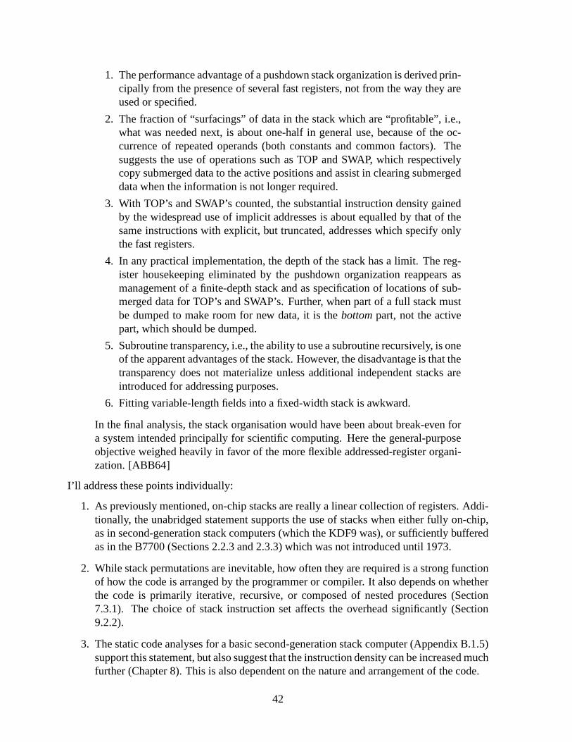
1. The performance advantage of a pushdown stack organization is derived prin-cipally from the presence of several fast registers, not from the way they areused or specified.
2. The fraction of “surfacings” of data in the stack which are“profitable”, i.e.,what was needed next, is about one-half in general use, because of the oc-currence of repeated operands (both constants and common factors). Thesuggests the use of operations such as TOP and SWAP, which respectivelycopy submerged data to the active positions and assist in clearing submergeddata when the information is not longer required.
3. With TOP’s and SWAP’s counted, the substantial instruction density gainedby the widespread use of implicit addresses is about equalled by that of thesame instructions with explicit, but truncated, addresseswhich specify onlythe fast registers.
4. In any practical implementation, the depth of the stack has a limit. The reg-ister housekeeping eliminated by the pushdown organization reappears asmanagement of a finite-depth stack and as specification of locations of sub-merged data for TOP’s and SWAP’s. Further, when part of a fullstack mustbe dumped to make room for new data, it is thebottompart, not the activepart, which should be dumped.
5. Subroutine transparency, i.e., the ability to use a subroutine recursively, is oneof the apparent advantages of the stack. However, the disadvantage is that thetransparency does not materialize unless additional independent stacks areintroduced for addressing purposes.
6. Fitting variable-length fields into a fixed-width stack isawkward.
In the final analysis, the stack organisation would have beenabout break-even fora system intended principally for scientific computing. Here the general-purposeobjective weighed heavily in favor of the more flexible addressed-register organi-zation. [ABB64]
I’ll address these points individually:
1. As previously mentioned, on-chip stacks are really a linear collection of registers. Addi-tionally, the unabridged statement supports the use of stacks when either fully on-chip,as in second-generation stack computers (which the KDF9 was), or sufficiently bufferedas in the B7700 (Sections 2.2.3 and 2.3.3) which was not introduced until 1973.
2. While stack permutations are inevitable, how often they are required is a strong functionof how the code is arranged by the programmer or compiler. It also depends on whetherthe code is primarily iterative, recursive, or composed of nested procedures (Section7.3.1). The choice of stack instruction set affects the overhead significantly (Section9.2.2).
3. The static code analyses for a basic second-generation stack computer (Appendix B.1.5)support this statement, but also suggest that the instruction density can be increased muchfurther (Chapter 8). This is also dependent on the nature andarrangement of the code.
42

4. Experiments done since show that a stack needs to be only 16to 32 elements deep tovirtually eliminate stack overflow to main memory [Koo89, 6.4.1] [Bai96, 4.2]. Whatmemory traffic remains can be mitigated by the hardware stackmanagement algorithmsthat have been discovered since [Koo89, 6.4.2] [Bai96, 6.2]. The abridged versionsof this statement omitted the trade-off between the register housekeeping required forsubroutine calls on register-based computers versus the stack housekeeping required foriterative code on stack-based computers.
5. I suspect the authors were thinking of the KDF9 since first-generation stack comput-ers exhibit subroutine transparency using a single stack. This is possible because theactivation record of an instance of a subroutine is stored inmain memory. For second-generation stack computers like the KDF9, whose stack is notrandomly accessible, asingle stack is insufficient since at the very least the arguments being passed recursivelywould be buried under the return address (Section 4.2). Thusat the minimum a secondstack is needed to hold return addresses.The statement is correct for both generations when index registers are used (Sections2.3.4 and 3.4.1) since unless they are also stacks themselves, nested subroutines whichuse them would have to do housekeeping to preserve and accesstheir values, effectivelyimplementing in software the stack of a first-generation stack computer at a great perfor-mance penalty. Finally, given integrated circuits, the cost of an extra stack is minimal.
6. Bell et al. are correct when saying that this point is irrelevant. The problem, if present,is orthogonal to the internal organization of a fixed-width machine.
In summary, the arguments quoted by Hennessy & Patterson were oversimplified and referredto old hardware and compiler technology. In fact, the original source of the arguments is farless critical of stacks than the version Bellet al. present and most of the shortcomings havebeen overcome since then.
43

44

Part III
Quantitative Arguments
45


Chapter 6
A Stack-Based Counterpart to DLX:Gullwing
I present the Gullwing1 processor architecture as an unpipelined, stack-based analogue of Hen-nesy and Patterson’s DLX [HP02]: a small design that is a simplified reflection of the currentstate of the art. Gullwing is closely based on the available descriptions of the MuP21, F21, andc18 processors (Chapter 3).
6.1 Block Diagram
Figure 6.1 shows the datapath components of the processor. The description is not entirelyabstract or free from implementation details. Some have been included for clarity and someare simply too compelling to ignore. Unless noted otherwise, the registers and memory are32 bits wide and contain integers. The depth of the stacks is arbitrary. See Section 5.5 for adiscussion of useful depths.
TOP +1 PC
A
MARALU
ISR
MEM adrdata
R
RS
DS
Figure 6.1: Gullwing Block-Level Datapath
5 5 5 5 5 5 2
5
32 MEM
5 5 5 5 5 55
INST
S0 S5S1 S4S2 S3
MSBLSB
x PC@
L
Figure 6.2: Gullwing Instruction Shift Regis-ter Block Diagram
1The name ’Gullwing’ was inspired by Richard Bach’s book, "Johnathan Livingston Seagull", and also by theDeLorean DMC-12 made famous in the "Back To The Future" movietrilogy by Robert Zemeckis and Bob Gale.
47

6.1.1 Memory Subsystem
At the top is the main memory (MEM), whose address port is continually driven by the Mem-ory Address Register (MAR). The MAR is itself loaded by one ofthe Address Register (A),the Program Counter (PC), or the Return Register (R). The contents of each of these can bemodified by a dedicated incrementer (+1). The MAR can also be loaded directly from memoryoutput in the case of jumps and calls, or from the incrementedversion of the PC in the case ofsubroutine returns.
The PC holds the address of the next memory word to be read for fetching instructions orliterals. Upon a subroutine call, it is stored into R, which is itself saved onto the Return Stack(RS). The reverse process occurs when a subroutine returns.
The A register is used under program control to hold the addresses of loads and stores, withoptional post-incrementing. The R register can be used in the same manner.
6.1.1.1 Single Memory Bus
In order to concentrate on the architecture of Gullwing, themain memory is abstracted awayto an idealized form. It has a single, bidirectional data busand a single, unidirectional addressbus2. One read or one write is possible per cycle. By default, the output of the memory isalways available for reading.
6.1.1.2 Differentiating Loads, Stores, and Fetches
If a read from memory simply reads the current memory output,it is termed a ’fetch’. Thereis no write equivalent to a fetch. If an explicit address is used to read or write to memory, it istermed a ’load’ or a ’store’, respectively. For example, in the next two sections it will be shownthat calls and jumps fetchtheir target address, but loadthe instructions from that location.
6.1.2 Computation Subsystem
At the far left, the Arithmetic and Logic Unit (ALU) always takes its inputs from the TopRegister (TOP) and the Data Stack (DS) and returns its outputto TOP, whose original contentsare optionally pushed onto the DS. The TOP register is the central point of gullwing. It is thesource and target for memory operations and can exchange data with the A and R registers.
6.1.3 Control Subsystem
Figure 6.2 shows the details of the Instruction Shift Register (ISR). The 32 bits of an instructionword are loaded into six 5-bit registers (S0 to S5), each holding one instruction, with the twomost significant bits (MSB) left unused3. The instruction in the least significant (LSB) positionis output as the current one being executed (INST). When INSTfinishes executing, the contents
2This is not the instruction fetch bottleneck it seems to be. See Section 6.3.1 for why a second bus wouldremain idle over 90% of the time.
3These two bits could be used as a seventh instruction taken from the set of instructions whose three MSBare always zero, or as subroutine return and call flags as in the NC4016 and RTX-2000. They are left unused forsimplicity.
48

of the instruction registers are shifted over by one instruction and filled-in at the far end with aProgram Counter Fetch (PC@) instruction (see Section 6.2).After the last loaded instructionis executed, the PC@ instruction fetches the next instruction group into the ISR.
If the instruction after INST is a PC@, then INST is the last one of this group. This issignalled by the Last line (L) being high during the execution of INST. If the encoding of PC@is conveniently chosen to be all zeroes, then L is simply the NOR of all the bits of S1. Thisline is used to overlap the execution of INST and PC@ wheneverpossible (Section 6.3.1).
6.2 Instruction Set
The Gullwing instruction set is identical to that of the F21 (Section 3.2.5), with some minorimplementation simplifications which are beneficial to pipelining (Section 7.4):
• To fetch instructions, the F21 uses an internal memory access delay triggered by a lackof memory-accessing instructions in its ISR. Gullwing instead uses a Program CounterFetch (PC@) instruction as the instruction fetching mechanism. It was the simplestchoice to implement and the most deterministic in behaviour. This also allows skippingof unused instruction slots, which would otherwise have to be filled with no-ops.
• The F21 call and jump instructions use the remainder of the ISR to hold the low-orderbits of the target address. The number of these bits depends on where in the ISR theinstruction is placed. These bits would replace the corresponding ones in the PC, provid-ing a limited branch distance relative to the current value of the PC. In Gullwing, the calland jump instructions take their target address from a memory address which follows theinstruction, usually the very next one. This allows uniform, absolute addressing over theentire memory range.
• Like the calls and jumps, literal fetches on the F21 also place their argument in theremaining low-order bits. In Gullwing, the literal fetch instruction takes its literal valuefrom a memory address which follows the instruction, usually the very next one. Thismakes for uniform and general storage of literals.
6.2.1 Instruction Packing
All instructions fit into 5-bit opcodes and have no operand fields or extended formats of anykind. Thus, up to six instructions can be packed into each 32-bit memory word (Section 6.2.7).This packing of instructions greatly reduces the number of instruction fetches for sequentialcode (Section 7.2.4) and makes possible a much higher code density (Chapter 8).
6.2.2 Flow Control
These instructions (Table 6.1) control the flow of executionof a program. They all access mem-ory and use full-word absolute addresses either explicitlyor implicitly. The jumps and callsfetch their target address from the next word in memory, while the PC@ and RET instructions
49
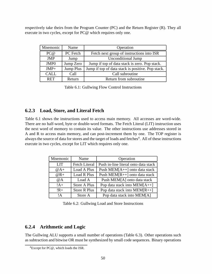
respectively take theirs from the Program Counter (PC) and the Return Register (R). They allexecute in two cycles, except for PC@ which requires only one.
Mnemonic Name Operation
PC@ PC Fetch Fetch next group of instructions into ISRJMP Jump Unconditional JumpJMP0 Jump Zero Jump if top of data stack is zero. Pop stack.JMP+ Jump Plus Jump if top of data stack is positive. Pop stack.CALL Call Call subroutineRET Return Return from subroutine
Table 6.1: Gullwing Flow Control Instructions
6.2.3 Load, Store, and Literal Fetch
Table 6.1 shows the instructions used to access main memory.All accesses are word-wide.There are no half-word, byte or double-word formats. The Fetch Literal (LIT) instruction usesthe next word of memory to contain its value. The other instructions use addresses stored inA and R to access main memory, and can post-increment them by one. The TOP register isalways the source of data for stores and the target of loads and fetches4. All of these instructionsexecute in two cycles, except for LIT which requires only one.
Mnemonic Name Operation
LIT Fetch Literal Push in-line literal onto data stack@A+ Load A Plus Push MEM[A++] onto data stack@R+ Load R Plus Push MEM[R++] onto data stack@A Load A Push MEM[A] onto data stack!A+ Store A Plus Pop data stack into MEM[A++]!R+ Store R Plus Pop data stack into MEM[R++]!A Store A Pop data stack into MEM[A]
Table 6.2: Gullwing Load and Store Instructions
6.2.4 Arithmetic and Logic
The Gullwing ALU supports a small number of operations (Table 6.3). Other operations suchas subtraction and bitwise OR must be synthesized by small code sequences. Binary operations
4Except for PC@, which loads the ISR.
50
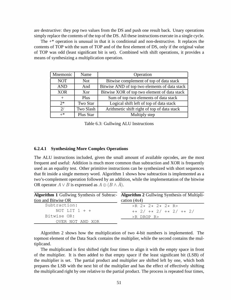
are destructive: they pop two values from the DS and push one result back. Unary operationssimply replace the contents of the top of the DS. All these instructions execute in a single cycle.
The +* operation is unusual in that it is conditional and non-destructive. It replaces thecontents of TOP with the sum of TOP and of the first element of DS, only if the original valueof TOP was odd (least significant bit is set). Combined with shift operations, it provides ameans of synthesizing a multiplication operation.
Mnemonic Name Operation
NOT Not Bitwise complement of top of data stackAND And Bitwise AND of top two elements of data stackXOR Xor Bitwise XOR of top two element of data stack
+ Plus Sum of top two elements of data stack2* Two Star Logical shift left of top of data stack2/ Two Slash Arithmetic shift right of top of data stack+* Plus Star Multiply step
Table 6.3: Gullwing ALU Instructions
6.2.4.1 Synthesizing More Complex Operations
The ALU instructions included, given the small amount of available opcodes, are the mostfrequent and useful: Addition is much more common than subtraction and XOR is frequentlyused as an equality test. Other primitive instructions can be synthesized with short sequencesthat fit inside a single memory word. Algorithm 1 shows how subtraction is implemented as atwo’s-complement operation followed by an addition, whilethe implementation of the bitwiseOR operatorA ∨ B is expressed asA ⊕ (B ∧ A).
Algorithm 1 Gullwing Synthesis of Subtrac-tion and Bitwise OR
Subtraction:NOT LIT 1 + +
Bitwise OR:OVER NOT AND XOR
Algorithm 2 Gullwing Synthesis of Multipli-cation (4x4)
>R 2* 2* 2* 2* R>+* 2/ + * 2/ + * 2/ + * 2/>R DROP R>
Algorithm 2 shows how the multiplication of two 4-bit numbers is implemented. Thetopmost element of the Data Stack contains the multiplier, while the second contains the mul-tiplicand.
The multiplicand is first shifted right four times to align itwith the empty space in frontof the multiplier. It is then added to that empty space if the least significant bit (LSB) ofthe multiplier is set. The partial product and multiplier are shifted left by one, which bothprepares the LSB with the next bit of the multiplier and has the effect of effectively shiftingthe multiplicand right by one relative to the partial product. The process is repeated four times,
51

shifting out the multiplier and leaving the completed 8-bitproduct on the top of the stack. Themultiplicand is then discarded.
This method produces one bit of product approximately everytwo cycles and is a compro-mise between full hardware and software implementations. Its disadvantage is that it is limitedto single-word products, and thus to half-word factors. However, it can also be optimized whenthe multiplier is much smaller than the multiplicand.
The multiplication of full-word factors, with a double-word product, could be accomplishedin the same way by shifting across two registers. For example, TOP could hold the multiplicandand A the multiplier. By having +* test the LSB of A, and 2/ shifting from TOP into A, theprocess would leave the lower half of the product in A and the upper half in TOP. ExecutingA> would then place both halves on the Data Stack.
6.2.5 Stack Manipulation
Table 6.4 shows the instructions which manipulate the stacks and move data internally. Theyexecute in one cycle.
Mnemonic Name Operation
A> A From Push A onto data stack>A To A Pop data stack into A
DUP Dup Duplicate top of data stackDROP Drop Pop data stackOVER Over Push copy of second element onto data stack
>R To R Pop data stack and push onto return stackR> R From Pop return stack and push onto data stack
Table 6.4: Gullwing Stack Manipulation Instructions
6.2.6 No-Op and Undefined
Finally, one instruction is defined as no operation (Table 6.5). It does nothing but fill an in-struction slot and use a machine cycle. The remaining four undefined instructions are mappedto NOP also.
Mnemonic Name Operation
NOP Nop Do NothingUND[0-3] Undefined Do Nothing
Table 6.5: Gullwing No-Op and Undefined Instruction
52

6.2.7 Instruction Format and Execution Example
Instruction opcodes are 5-bit numbers. Six of these can be packed into a 32-bit memory word.The last two bits are unused (see Section 6.1.3). Literals and addresses always occupy an entireword. Each instruction position is termed a slot and the slots in a word constitute an instructiongroup. After a group is fetched, the instructions in the slots are executed in turn until they areexhausted. Figure 6.3 shows the memory layout of a random snippet of code tailored to showthe layout of the instructions. They are laid out in left-to-right order for convenience only.
In the initial state of this example, the group at address 1 has just been fetched, the instruc-tion in Slot 0 (S0) is about to be executed, and the Program Counter (PC) has been incrementedto point to address 2. The first instruction (>R) executes without comment and shifts the con-tents of the ISR to the left by one instruction, placing JMP0 as the current instruction.
In the case of the JMP0 conditional jump being not taken, the PC is incremented by one topoint to address 3, and the execution continues with DUP. When the LIT instruction is reachedit fetches the literal pointed-to by the PC (at address 3) andincrements the PC by one. Theaddition instruction is then executed.
When the PC@ instruction is reached, it fetches a new group from the location pointed toby the PC, which is currently address 4, and then increments the PC. Eventually the CALLinstruction is reached. It loads the instruction group fromthe target address in the memoryword pointed to by PC (at address 5), and loads the PC with the target address plus one. Theremaining slots are never executed and are filled by convention with PC@.
Had the JMP0 conditional jump been taken, it would have executed similarly to the CALLinstruction, loading the group at address 4 and leaving the PC pointing to address 5. The strictlyword-wide access to memory is why the R> in Slot 0 at address 4 could not be placed in Slot 5at address 1. Jumping or calling to an address always begins executing at Slot 0.
>R JMP0
Number for LIT
Address for CALLR>
12345
Address for JMP0 (4)
XOR
+
CALL PC@ PC@ PC@
PC@LITDUPS0 S2 S3 S4S1 S5
Figure 6.3: Gullwing Instruction Format
53

6.3 State Machine and Register Transfer Description
The operation of the unpipelined Gullwing processor is verysimple. There are no exceptions orinterrupts. Algorithms 3 through 4 show the state transitions and register transfers. The inputsof its state machine consist of the opcode of the current instruction (INST), the current state(S), and whether the contents of the TOP register is all zeroes (=0), has the most significant bitclear (MSB0), or has the least significant bit set (LSB1). These three flags have been collapsedinto a single input column (TOP) for brevity. ’Don’t Care’ values are represented by X. Theoutputs are the next state (N) and the various enable and select signals needed to steer thedatapath, which are represented symbolically.
All actions on a line occur concurrently. For example, the operation of PC@ can be under-stood as: leave the state at zero, route the PC through the incrementer (+1) and store its outputinto both PC and MAR, and load the ISR with the current output of MEM. All instructions endwith either loading or shifting the ISR (ISR< <), which changes INST to the next instructionto execute (see Figure 6.2). Instructions that take two cycles use the state bit to select whichphase to execute.
Instructions which load instructions from memory, such as CALL and JMP, execute thesame sequence of steps as PC@ in their second phase. For brevity, these steps have beenreplaced with the opcode.
Algorithm 3 Gullwing Flow Control InstructionsInputs Outputs----------- ---------INST TOP S N Control---- --- - - -------PC@ X 0 0 PC→(+1) →PC,MAR, MEM→ISRJMP X 0 1 MEM→PC,MARJMP X 1 0 PC@JMP0 =0 0 1 DS→TOP, DS(POP), MEM→PC,MARJMP0 !=0 0 0 DS→TOP, DS(POP), PC →(+1) →PC,MAR, ISR< <JMP0 X 1 0 PC@JMP+ MSB0 0 1 DS→TOP, DS(POP), MEM→PC,MARJMP+ MSB1 0 0 DS→TOP, DS(POP), PC →(+1) →PC,MAR, ISR< <JMP+ X 1 0 PC@CALL X 0 1 PC→(+1) →R, R→RS, RS(PUSH), MEM→MAR,PCCALL X 1 0 PC@RET X 0 1 RS(POP), RS→R, R→PC,MARRET X 1 0 PC@
Algorithm 4 Gullwing No-Op and Undefined InstructionsInputs Outputs Inputs Outputs---------- --------- ---------- ---------INST TOP S N Control INST TOP S N Control---- --- - - ------- ---- --- - - -------NOP X 0 0 ISR< < UND2 X 0 0 ISR< <UND0 X 0 0 ISR< < UND3 X 0 0 ISR< <UND1 X 0 0 ISR< <
54
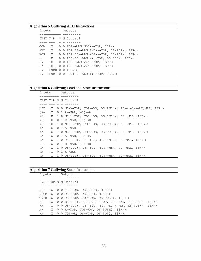
Algorithm 5 Gullwing ALU InstructionsInputs Outputs----------- ---------INST TOP S N Control---- --- - - -------COM X 0 0 TOP→ALU(NOT)→TOP, ISR< <AND X 0 0 TOP,DS→ALU(AND)→TOP, DS(POP), ISR< <XOR X 0 0 TOP,DS→ALU(XOR)→TOP, DS(POP), ISR< <+ X 0 0 TOP,DS→ALU(+) →TOP, DS(POP), ISR< <2* X 0 0 TOP→ALU(2 * ) →TOP, ISR< <2/ X 0 0 TOP→ALU(2/) →TOP, ISR< <+* LSB0 0 0 ISR< <+* LSB1 0 0 DS,TOP→ALU(+) →TOP, ISR< <
Algorithm 6 Gullwing Load and Store InstructionsInputs Outputs---------- ---------INST TOP S N Control---- --- - - -------LIT X 0 0 MEM→TOP, TOP→DS, DS(PUSH), PC →(+1) →PC,MAR, ISR< <@A+ X 0 1 A→MAR,(+1) →A@A+ X 1 0 MEM→TOP, TOP→DS, DS(PUSH), PC →MAR, ISR< <@R+ X 0 1 R→MAR,(+1) →R@R+ X 1 0 MEM→TOP, TOP→DS, DS(PUSH), PC →MAR, ISR< <@A X 0 1 A→MAR@A X 1 0 MEM→TOP, TOP→DS, DS(PUSH), PC →MAR, ISR< <!A+ X 0 1 A →MAR,(+1) →A!A+ X 1 0 DS(POP), DS →TOP, TOP→MEM, PC→MAR, ISR< <!R+ X 0 1 R→MAR,(+1) →R!R+ X 1 0 DS(POP), DS →TOP, TOP→MEM, PC→MAR, ISR< <!A X 0 1 A →MAR!A X 1 0 DS(POP), DS →TOP, TOP→MEM, PC→MAR, ISR< <
Algorithm 7 Gullwing Stack InstructionsInputs Outputs---------- ---------INST TOP S N Control---- --- - - -------DUP X 0 0 TOP→DS, DS(PUSH), ISR< <DROP X 0 0 DS→TOP, DS(POP), ISR< <OVER X 0 0 DS→TOP, TOP→DS, DS(PUSH), ISR< <R> X 0 0 RS(POP), RS→R, R→TOP, TOP→DS, DS(PUSH), ISR< <>R X 0 0 DS(POP), DS→TOP, TOP→R, R→RS, RS(PUSH), ISR< <A> X 0 0 A→TOP, TOP→DS, DS(PUSH), ISR< <>A X 0 0 TOP→A, DS→TOP, DS(POP), ISR< <
55

6.3.1 Improvement: Instruction Fetch Overlap
Using an instruction (PC@) to fetch the next group of instructions eliminates the need fordedicated instruction-fetching hardware. The fact that itis also shifted into the ISR for free isalso very elegant. However, this means that at least one out of every seven instructions executedwill be a PC@, or about 14%5. This overhead could be reduced by overlapping fetching withexecution while the memory bus is free.
A priori, it is unclear how much benefit would come from overlapping the instruction fetch.Koopman provides a table of the dynamic instruction execution frequencies of Forth primitivesaveraged over a set of benchmarks [Koo89, 6.3]. These primitives map almost directly to theGullwing instruction set and the benchmarks from Section 7.1 are also written in a Forth-likelanguage. The data predicts that approximately half of the executed primitives are either flowcontrol or load/store instructions and thus access memory.Assuming that this probability isevenly distributed, the fetching of instructions could be overlapped half the time, reducing theoverhead to about 7% for straight-line code.
Accomplishing this overlap depends on this fact: If the the last instruction before a PC@does not access memory, then both instructions can be executed simultaneously without con-flict. Figure 6.2 shows how the ISR makes this possible. If thenext instruction to be executedis a PC@6, then the current instruction being executed is the last oneof this group. This issignalled by raising the Last flag (L). If the current instruction does not access memory7, theninstead of shifting the ISR at the end of its execution, the instruction will fetch the next groupof instructions from memory in the same manner as PC@, as if ithad executed concurrently.
Implementing this optimization requires adding the L bit asan input to the state machine.Flow control and load/store instructions ignore this bit since they always access memory. Theremaining instructions now have two versions, selected by L, which either shift or load the ISR.Algorithms 8, 9, and 10 show the necessary changes.
Analysis of code executed with an overlapping instruction fetch (Appendix B.2.2) confirmsthat the actual overhead of explicit PC@ instructions is reduced to 4.1 to 2.2% of the totalexecuted instructions . It also shows that 4.2 to 7.5% of instructions are executed concurrently(’FOLDS’) with a PC@. This demonstrates a 50.6 to 77.3% reduction in instruction fetchoverhead.
5The actual overhead will be lower since other flow control instructions do their own instruction loading.Without instruction fetch overlapping the actual overheadof instruction fetching is 8.3 to 9.7%.
6PC@ is conveniently encoded as all zeroes.7Since the opcodes are divided about equally between memory and non-memory instructions, a single bit (the
MSB, for example) can be used to test if the instruction accesses memory. This should simplify the implementa-tion of the state machine.
56

Algorithm 8 Gullwing ALU Instructions with Instruction Fetch OverlapInputs Outputs------------- ---------INST TOP L S N Control---- --- - - - -------COM X 0 0 0 TOP→ALU(NOT)→TOP, ISR< <COM X 1 0 0 TOP→ALU(NOT)→TOP, PC@AND X 0 0 0 TOP,DS→ALU(AND)→TOP, DS(POP), ISR< <AND X 1 0 0 TOP,DS→ALU(AND)→TOP, DS(POP), PC@XOR X 0 0 0 TOP,DS→ALU(XOR)→TOP, DS(POP), ISR< <XOR X 1 0 0 TOP,DS→ALU(XOR)→TOP, DS(POP), PC@+ X 0 0 0 TOP,DS→ALU(+) →TOP, DS(POP), ISR< <+ X 1 0 0 TOP,DS→ALU(+) →TOP, DS(POP), PC@2* X 0 0 0 TOP→ALU(2 * ) →TOP, ISR< <2* X 1 0 0 TOP→ALU(2 * ) →TOP, PC@2/ X 0 0 0 TOP→ALU(2/) →TOP, ISR< <2/ X 1 0 0 TOP→ALU(2/) →TOP, PC@+* LSB0 0 0 0 ISR< <+* LSB0 1 0 0 PC@+* LSB1 0 0 0 DS,TOP→ALU(+) →TOP, ISR< <+* LSB1 1 0 0 DS,TOP→ALU(+) →TOP, PC@
Algorithm 9 Gullwing Stack Instructions with Instruction Fetch OverlapInputs Outputs------------ ---------INST TOP L S N Control---- --- - - - -------DUP X 0 0 0 TOP→DS, DS(PUSH), ISR< <DUP X 1 0 0 TOP→DS, DS(PUSH), PC@DROP X 0 0 0 DS→TOP, DS(POP), ISR< <DROP X 1 0 0 DS→TOP, DS(POP), PC@OVER X 0 0 0 DS→TOP, TOP→DS, DS(PUSH), ISR< <OVER X 1 0 0 DS→TOP, TOP→DS, DS(PUSH), PC@R> X 0 0 0 RS(POP), RS→R, R→TOP, TOP→DS, DS(PUSH), ISR< <R> X 1 0 0 RS(POP), RS→R, R→TOP, TOP→DS, DS(PUSH), PC@>R X 0 0 0 DS(POP), DS→TOP, TOP→R, R→RS, RS(PUSH), ISR< <>R X 1 0 0 DS(POP), DS→TOP, TOP→R, R→RS, RS(PUSH), PC@A> X 0 0 0 A→TOP, TOP→DS, DS(PUSH), ISR< <A> X 1 0 0 A→TOP, TOP→DS, DS(PUSH), PC@>A X 0 0 0 TOP→A, DS→TOP, DS(POP), ISR< <>A X 1 0 0 TOP→A, DS→TOP, DS(POP), PC@
Algorithm 10 Gullwing No-Op and Undefined Instructions with InstructionFetch OverlapInputs Outputs Inputs Outputs------------ --------- ------------ ---------INST TOP L S N Control INST TOP L S N Control---- --- - - - ------- ---- --- - - - -------NOP X 0 0 0 ISR< < UND1 X 1 0 0 PC@NOP X 1 0 0 PC@ UND2 X 0 0 0 ISR< <UND0 X 0 0 0 ISR< < UND2 X 1 0 0 PC@UND0 X 1 0 0 PC@ UND3 X 0 0 0 ISR< <UND1 X 0 0 0 ISR< < UND3 X 1 0 0 PC@
57

58

Chapter 7
Comparisons With DLX/MIPS
As stated in Section 1.1, this thesis aims to divide the family of stack-based computers into firstand second generations. Part of this distinction consists of showing that the second generationresembles the register-based machines which replaced the first.
This chapter supports this argument by comparing the Gullwing processor from Chapter 6with the well-known MIPS and DLX processors used as demonstrators by Hennessy & Pat-terson. This comparison is based on statistics derived fromthe organization and execution ofprograms and further based on a comparison of the pipeline structure of each microprocessor.The characteristics compared include: cycle time, cycle count, cycles per instruction, instruc-tion count, dynamic instruction mix, memory accesses per cycle, code size, and code density.
7.1 Gullwing Benchmarks
Unfortunately, C compilers for second-generation stack computers are rare and, when avail-able, are proprietary or experimental. Additionally, there are no existing operating systems orperipherals for Gullwing. Thus, it is not possible at the time to compile the SPEC benchmarksfor this platform. The software used to test Gullwing performs mostly symbol table searchesand machine code compilation and interpretation. It could be loosely viewed as a tiny subsetof the GCC, Lisp, and Perl components of the SPECint benchmarks.
The software was originally written to explore a Forth-likeself-extensible language, named’Flight’. It is composed of a language kernel used to compileextensions to itself, includinga metacompiler and a Gullwing virtual machine, which are then used to re-create the Flightlanguage kernel and all its extensions in a self-hosting manner. This process is described in thefollowing subsections. The source for all the benchmarks islisted in Appendix A.
7.1.1 Flight Language Kernel (Bare)
The Flight language kernel is a small (about 800 32-bit memory words) piece of machine code.Its main loop reads in a name, searches for it in a linear dictionary and if found, calls thefunction associated with that name. The kernel’s other built-in functions include managementof a linear input buffer, string comparison, creation of dictionary entries, conversion of decimalnumbers to binary, and compilation of the Gullwing opcodes.Source code fed to the kernel
59
is executed as it is received and can contain the name of any built-in or previously definedfunction. The source to the kernel is listed in Appendix A.1.
7.1.2 Flight Language Extensions (Ext.)
The language defined by the Flight kernel is extremely spartan. The Flight extensions beginby creating convenience functions to simplify the definition, lookup, and compilation of otherfunctions. These are used to create various functions for string copying, compilation, andprinting, multiplication and division of integers, binaryto decimal conversion, and a simple’map’ function generator. These new function are used to construct small demonstrations ofFibonacci numbers and Caesar ciphers. These demonstrations account for a negligible portionof the total execution time and are used mainly as regressiontests for the underlying code.The Flight language extensions exercise the functions of the Flight kernel and are composedof 329 lines of code1 containing 1710 names2 and executing 5,018,756 instructions (4,462,579without the demonstrations). The source is listed in Appendix A.2.
7.1.3 Virtual Machine (VM)
The virtual machine is built upon the Flight extensions3 (without demonstration code). It de-fines a software emulation of all the Gullwing opcodes, some bounds-checking functions for agiven area of memory, and an instruction extraction and interpretation loop that reads Gullwingmachine code. Compiled code executes in the virtual machinewith an overhead of about 31emulator instructions per actual emulated instruction. The end result is a fully contained emu-lation of the Gullwing microprocessor. The compilation of the virtual machine itself requires276 lines of code containing 769 names. This process exercises the functions of the kernel andits extensions and executes 4,288,157 instructions. The source is listed in Appendix A.3.1.
Metacompiler The metacompiler manipulates the Flight kernel to retargetits operations tothe memory area used by the virtual machine. It saves and restores the internal state of thekernel, such as the location of the dictionary and input buffer, and defines a new main loopto replace the kernel’s default one. The new loop first searches the new dictionary in thevirtual machine memory and if there is no match, continues the search in the kernel’s originaldictionary. This allows the use of functions previously defined outside of the virtual machineto bootstrap code inside it. The compilation of the metacompiler requires 106 lines of codecontaining 491 names. This process exercises the functionsof the kernel and its extensions andexecutes 4,069,393 instructions. The source is listed in Appendix A.3.2.
Self-Hosted Kernel The first thing compiled into the virtual machine is another instance ofthe Flight kernel. While the original kernel was written in assembly language, this new kernel
1Only non-blank lines are counted.2Each name is either a function name, or a string to be processed.3Although the Virtual Machine software includes the compilation of the Extensions, the latter contributes to
only 2.2% of the total number of executed instructions.
60
is defined using the functions of the original kernel and all its extensions. The result is a higher-level description of the Flight kernel, written in itself. The new kernel binary residing in thevirtual machine memory area is identical to the original4. The compilation of the self-hostedkernel requires 246 lines of code containing 681 names. Thisprocess exercises the functionsof the kernel and its extensions via the indirection of the metacompiler and executes 6,511,976instructions. The source is listed in Appendix A.3.3.
Flight Language Kernel Extensions Now that a Flight kernel resides in the virtual machinememory, is it possible to start the virtual machine and execute this new kernel. The Flightlanguage extensions from Section 7.1.2 are fed to the new kernel, exercising the same code,but through the emulation layer of the virtual machine. Thisexecutes 184,993,301 instructions,taking about 90% of the total execution time of the VM test suite.
7.2 Comparison of Executed Benchmark Code
This section compares the properties of Gullwing and DLX/MIPS when executing integer code.The DLX/MIPS data is derived from published SPECint92 [HP96, fig. 2.26] and SPECint2000[HP02, fig. 2.32] results. The Gullwing data (Appendix B) is compiled from the execution ofsoftware built upon the kernel of a low-level Forth-like language, named ’Flight’, tailored toGullwing (Appendix A). The properties compared are dynamicinstruction mix, cycles perinstruction (CPI), memory accesses per cycle, and instructions per memory word.
Note that while the DLX and MIPS processors include optimizations such as operand for-warding, the Gullwing processor has none except for the instruction fetch overlapping de-scribed in Section 6.3.1. Other optimizations have been left for future work (Section 9.2).
7.2.1 Dynamic Instruction Mix
Tables 7.1 and 7.2 compare the proportions of instructions executed during the benchmarks.The Gullwing data is taken from the Extensions and Virtual Machine executed instructioncounts from Appendix B.2.2. Since the Extensions software deals mainly with code com-pilation, it is compared to the GCC component of the SPECint92 and SPECint2000 suites.The Virtual Machine software is compared to the other interpretive components: Lisp fromSPECint92 and Perl from SPECint2000.
The Gullwing instructions are grouped together and their statistics summed in order tomatch the meaning of the equivalent DLX/MIPS instructions.For example, while MIPS hasone load instruction for all purposes, Gullwing has different ones (@A, @A+, @R+) dependingon the addressing mode and the load address register.
The statistics for the XOR and NOT instructions are combinedsince the SPECint92 datagroups them together even though the SPECint2000 data liststhem separately5. Statistics for
4Actually, there is a gap of one memory word between functionsdue to a quirk of the compilation process, butthe actual code is the same.
5From SPECint2000 data:Table 7.1: 2.8% XOR, plus 0.3% other logical ops.Table 7.2: 2.1% XOR, plus 0.4% other logical ops.
61

instructions which do not exist in a given machine are represented by a dash (’-’).For both the compiler and interpreter test data, the dynamicinstruction mix of the Gullwing
processor differs from that of DLX and MIPS in some significant ways:
• The proportion of loads and stores is lower. I believe this originates from a lack ofcomplex data structures in the Gullwing software, and the need for DLX and MIPS touse a stack in main memory to pass parameters to subroutines.
• There are many more immediate loads (fetches) since Gullwing cannot include smallliteral operands within most instructions as DLX and MIPS do.
• The proportion of calls and returns is much greater. The stack-based architecture ofGullwing results in extremely efficient procedure linkage,which makes the inlining ofcode unnecessary in most cases.
• About a quarter of all the instructions executed are stack manipulation instructions. Someare manipulations made explicit by the absence of operands in Gullwing instructions asa consequence of the lack of random access to a stack. DLX and MIPS include implicitmove, copy, and delete operations within their instructions by using a three-operandinstruction format which gives random access to their registers. A large portion of thesestack manipulations are moves of addresses from the top of the Data Stack to the AddressRegister, as performed by the >A instruction. Section 9.2.3discusses a mean to reducethe overhead of these moves.
Additionally, the interpreter dynamic instruction mix (Table 7.2) has some further differences:
• The proportion of conditional jumps is lower on Gullwing. This is likely because ofthe lack of conditionals in the main VM loop, which uses instead a table of functionaddresses.
• The large incidence of shifts is due to the use of the shift-left (2/) instruction in the VMto extract individual instructions out of a memory word.
62

Benchmark GCC (92) GCC (2000) Extensions
DLX/MIPS Instr. DLX MIPS Gullwing Gullwing Instr.
load 22.8% 25.1% 15.2% @A, @A+, @R+store 14.3% 13.2% 0.4% !A, !A+, !R+add 14.6% 19.0% 10.3% +sub 0.5% 2.2% -mul 0.1% 0.1% -div 0.0% - -
compare 12.4% 6.1% -load imm 6.8% 2.5% 16.8% LIT, PC@
cond branch 11.5% 12.1% 6.6% JMP0, JMP+(incl. TAKEN jumps)
cond move - 0.6% -jump 1.3% 0.7% 2.1% JMPcall 1.1% 0.6% 6.4% CALL
return, jmp ind 1.5% 0.6% 6.4% RETshift 6.2% 1.1% 0.2% 2/, 2*and 1.6% 4.6% 0% ANDor 4.2% 8.5% -
other (xor, not) 0.5% 2.5% 6.5% XOR, NOTother (moves) - - 29.2% DUP, DROP, OVER,
>R, R>, >A, A>other - - 0% NOP, +*
Table 7.1: Compilers Dynamic Instruction Mix
63
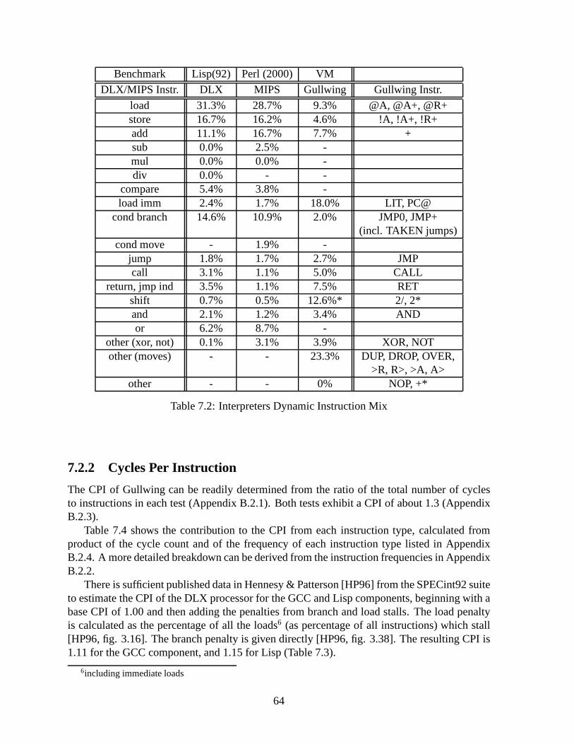
Benchmark Lisp(92) Perl (2000) VM
DLX/MIPS Instr. DLX MIPS Gullwing Gullwing Instr.
load 31.3% 28.7% 9.3% @A, @A+, @R+store 16.7% 16.2% 4.6% !A, !A+, !R+add 11.1% 16.7% 7.7% +sub 0.0% 2.5% -mul 0.0% 0.0% -div 0.0% - -
compare 5.4% 3.8% -load imm 2.4% 1.7% 18.0% LIT, PC@
cond branch 14.6% 10.9% 2.0% JMP0, JMP+(incl. TAKEN jumps)
cond move - 1.9% -jump 1.8% 1.7% 2.7% JMPcall 3.1% 1.1% 5.0% CALL
return, jmp ind 3.5% 1.1% 7.5% RETshift 0.7% 0.5% 12.6%* 2/, 2*and 2.1% 1.2% 3.4% ANDor 6.2% 8.7% -
other (xor, not) 0.1% 3.1% 3.9% XOR, NOTother (moves) - - 23.3% DUP, DROP, OVER,
>R, R>, >A, A>other - - 0% NOP, +*
Table 7.2: Interpreters Dynamic Instruction Mix
7.2.2 Cycles Per Instruction
The CPI of Gullwing can be readily determined from the ratio of the total number of cyclesto instructions in each test (Appendix B.2.1). Both tests exhibit a CPI of about 1.3 (AppendixB.2.3).
Table 7.4 shows the contribution to the CPI from each instruction type, calculated fromproduct of the cycle count and of the frequency of each instruction type listed in AppendixB.2.4. A more detailed breakdown can be derived from the instruction frequencies in AppendixB.2.2.
There is sufficient published data in Hennesy & Patterson [HP96] from the SPECint92 suiteto estimate the CPI of the DLX processor for the GCC and Lisp components, beginning with abase CPI of 1.00 and then adding the penalties from branch andload stalls. The load penaltyis calculated as the percentage of all the loads6 (as percentage of all instructions) which stall[HP96, fig. 3.16]. The branch penalty is given directly [HP96, fig. 3.38]. The resulting CPI is1.11 for the GCC component, and 1.15 for Lisp (Table 7.3).
6including immediate loads
64

The higher CPI of Gullwing does not compare favourably with that of DLX. However,loads and taken jumps on Gullwing take two cycles, which is asif a load or branch stall alwaysoccurred. Therefore, Gullwing is really architecturally equivalent to a DLX without load delayslots and without delayed branches, which always stalls on loads and taken branches. Forexample, if 100% of loads are assumed to stall on DLX, their load penalty increases to 29.6%for GCC and 33.7% for Lisp, which raises the total CPI of DLX to1.34 and 1.41 respectively,which is comparable to Gullwing.
Correspondingly, there are some possible optimizations toGullwing which would reducethe CPI of loads and jumps and make Gullwing equivalent to a normal DLX (Section 9.2.3).
Test GCC Lisp
Total Loads 29.6% 33.7%Load Stalls 23% 24%
Load Penalty 6.81% 8.10%
Branch Penalty 4% 7%
Total Penalty 10.8% 15.1%
Overall CPI 1.11 1.15
Table 7.3: DLX CPI with Load and BranchPenalties
Test Extensions VM
Instr. Type Fraction of Total CPI
Conditionals 0.071 0.031Subroutine 0.300 0.304
Fetches 0.168 0.180Load/Store 0.312 0.276
ALU 0.169 0.277Stack 0.292 0.233
Total 1.312 1.301
Table 7.4: Gullwing CPI by Instruction Type
7.2.3 Memory Accesses Per Cycle
The memory bandwidth usage of a processor can be expressed asthe average number of mem-ory accesses per cycle. Assuming a memory access time equal to the cycle time of the proces-sor, one memory access per cycle implies full usage of the available bandwidth to memory.
For the MIPS and DLX processors, determining the memory bandwidth usage is straight-forward. An instruction is fetched and another completed every cycle, assuming no stalls.Only load and store instructions explicitly access memory otherwise. Immediate operands arewithin the instruction opcode and so are counted as part of the instruction fetches. Large num-bers which require two loads are rare and ignored. Flow control instructions do not add to theinstruction fetches since they only steer the Instruction Fetch pipeline stage.
Table 7.6 takes data from the benchmarks of Section 7.2.1 andshows that loads and storesmake up on average 42.1% of the total number of executed instructions. Thus, they contributean additional average of 0.421 memory accesses per cycle. When added to the instructionfetches, this totals to an average 1.421 memory accesses percycle for DLX/MIPS, dividedbetween separate instruction and data memories.
Measuring the memory usage of Gullwing is a little more complicated. There is no pipeline.Several instructions are loaded in one memory access (see next section and Section 6.2.7). Flowcontrol instructions do their own fetching or loading of instructions. There are no immediateoperands. Different instructions take different numbers of cycles to execute and make differentnumbers of memory accesses. However, there is only one memory for both instruction and
65

data fetches/loads and thus only one Memory Address Register (MAR) (Section 6.1.1). Thus,a memory access is defined as an alteration of the MAR.
The average number of memory accesses per cycle for an instruction is calculated as so:
Avg. # of accesses/cycle = (# of accesses ÷ # of cycles) × avg. fraction of total cycles
The number of accesses is determined from the register transfer description (Section 6.3)as is the number of cycles, which can alternately be seen in Appendix B.2.4. The percentage oftotal cycles is listed under the C/C column in Appendix B.2.2. Table 7.5 condenses this data.
In summary, the Gullwing processor performs an average of 0.667 memory accesses percycle while using a single memory bus, compared to 1.421 for DLX/MIPS which uses two.
It would be ideal to reduce Gullwing’s memory bandwidth further, but part of the reasonit is already low is because of the extra instructions required to manipulate the stack (whichdo not access memory). Reducing this instruction overhead will increase the proportion ofmemory-accessing instructions and thus increase the average number of memory accesses percycle, towards a maximum of one (Section 9.2.3).
Either way, since loads and stores cannot (and have no need to) overlap instruction fetcheson Gullwing, the maximum number of memory accesses per cyclecannot exceed one. Bycomparison, MIPS must have aminimumof one memory access per cycle. When MIPS mustmanipulate its call stack, it must perform additional memory accesses in the form of data loadsand stores, increasing its memory bandwidth further7.
Test Extensions VM
Instruction Accesses Cycles Acc./Cyc. Fraction of Total Cycles
PC@ 1 1 1 0.031 0.017FOLDS 1 1 1 0.032 0.058CALL 2 2 1 0.098 0.076JMP 2 2 1 0.033 0.042
JMP0, JMP+ 1 1 1 0.046 0.009JMP0, JMP+ (TAKEN) 2 2 1 0.007 0.001
RET 2 2 1 0.098 0.115LIT 1 1 1 0.097 0.122
@A, @A+, @R+ 2 2 1 0.233 0.142!A, !A+, !R+ 2 2 1 0.006 0.070
all others 0 1 0 0.352 0.392
Total of (Acc./Cyc.) × Fraction 0.681 0.652
Average 0.667
Table 7.5: Gullwing Memory Accesses Per Cycle (Total)
7Implying, of course, a second memory bus.
66

Test Compiler InterpreterCPU DLX MIPS DLX MIPS
Component GCC92 GCC00 Lisp Perl
Loads 22.8% 25.1% 31.3% 28.7%Stores 14.3% 13.2% 16.7% 16.2%
Total 37.1% 38.3% 48.0% 44.9%
Average 37.7% 46.5%
Average 42.1%
Table 7.6: DLX/MIPS Memory Accesses Per Cycle Caused by Loads and Stores
7.2.4 Instructions per Memory Word
For DLX/MIPS, the density of code in memory is simple: there is exactly one instruction permemory word. The opcode and its operands or literals are contrived to fit. For Gullwing,opcodes have no explicit operands and literals are placed inthe next memory word (Section6.2.7). This allows up to six instruction opcodes to fit in a single memory word. The actualnumber is variable due to the word-addressed nature of jumps, calls, and returns.
However, if the total number of instructions is compared to the total number of instructionslots (Appendix B.1.5), it is apparent that most of the available instruction slots are wasted.Chapter 8 explains why and shows a method to make these wastedslots available.
Appendix B.1.4 shows that in most cases there is one, two, or six instructions per word thatcontains instructions (instead of a literal). The ones and twos imply higher-level code wherethe memory word contains a call or jump, while the sixes are low-level code without changes inprogram flow. The result is an overall code density of about 1.2 instructions per memory word(Appendix B.1.5). If the words containing literals and addresses are excluded, the averagememory word containing instructions contains between two and three instructions.
Despite the modest overall increase in code density, the higher density of words whichcontain instructions reduces the number of memory accessesrequired to fetch instructions.Until a group of instructions is exhausted, the memory bus isfree for loads and stores, and forfetching addresses and literals and the next instruction word also.
Gullwing spends 0.441 memory accesses per cycles to fetch orload instructions8, comparedto 1.00 for MIPS. The fraction of all memory accesses used forfetching or loading instructionson Gullwing is still approximately the same relative to MIPS(66.1% versus 70.4%, based onSection 7.2.3). Therefore, the important benefit of packingmultiple instructions per memoryword is not so much a reduction in code size, as one in instruction fetch memory bandwidth.
8Calculated as the sum of the fraction of total memory accesses done by instructions which alter the ProgramCounter (PC): PC@, FOLDS, CALL, RET, all JMPs, and LIT, averaged over both the Ext. and VM tests.
67

7.2.4.1 Basic Blocks and Instruction Fetch Overhead
This reduction in the number of instruction fetches manifests as a reduction of the number ofPC Fetch (PC@) instructions required to load the next sequential instruction word. If a basicblock of code spans several memory words, the last instruction in each word will be a PC@which fetches the next group of instructions (Sections 6.2.7 and 6.3.1). The call and jumpinstructions that terminate basic blocks do their own instruction loading.
Appendix B.2.5 shows that the average length of a basic block, measured in instructions,fits well within the six instruction slots in each memory word. In fact, 71.1 to 80.9% of basicblocks fit in a single memory word. This places a limit on how much overhead the PC@instructions can cause.
This PC@ overhead drops as the memory word gets wider and moreinstructions can bepacked in one. At the limit, when all basic blocks fit into one memory word, no PC@ in-structions will be executed and all loading of instructionswill come from calls and jumps. Ineffect, each memory word behaves as a cache line. This effectis amplified by the mechanismproposed in Chapter 8.
7.3 Behaviour of Iteration, Recursion, and Subroutine Calls
A clearer understanding of the differences between Gullwing and MIPS is obtained by com-paring the behaviour of simple, demonstrative programs written for both processors. Thesedemonstrators are examples of universal small-scale features of code, regardless of the higherlanguage used: iteration, recursion, and subroutine calls. They are not meant as benchmarks ofoverall performance, but as precise, singular tests made toexpose the low-level details of howeach processor executes code, unclouded by the complexities and biases of actual purpose-ful software. A direct comparison can be made between both processors since the algorithmsand implementation styles are identical, contrary to the heterogeneous tests from the previoussection.
7.3.1 Measured Properties
The code examples given are simple enough that their properties do not depend on input dataand can thus be determined by inspection. The properties aremeasured for a single algo-rithm step, which is one loop, recursive call, or sequence ofsubroutine calls. For looping andtail-recursive code, only the code inside the loop is considered since the entry and exit codecontribute a fixed amount regardless of the number of iterations. For recursive and subroutinecode, the entire code is considered. The measured properties are:
Memory Words This is a measure of code size, assuming 32-bit memory words.Instructionsare displayed such that one line represents one word of memory.
Instructions This is the number of instructions executed. All other things being equal, adifference in number suggests a difference in suitability to the given task.
68
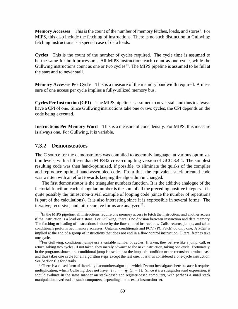
Memory Accesses This is the count of the number of memory fetches, loads, and stores9. ForMIPS, this also include the fetching of instructions. Thereis no such distinction in Gullwing:fetching instructions is a special case of data loads.
Cycles This is the count of the number of cycles required. The cycle time is assumed tobe the same for both processors. All MIPS instructions each count as one cycle, while theGullwing instructions count as one or two cycles10. The MIPS pipeline is assumed to be full atthe start and to never stall.
Memory Accesses Per Cycle This is a measure of the memory bandwidth required. A mea-sure of one access per cycle implies a fully-utilized memorybus.
Cycles Per Instruction (CPI) The MIPS pipeline is assumed to never stall and thus to alwayshave a CPI of one. Since Gullwing instructions take one or twocycles, the CPI depends on thecode being executed.
Instructions Per Memory Word This is a measure of code density. For MIPS, this measureis always one. For Gullwing, it is variable.
7.3.2 Demonstrators
The C source for the demonstrators was compiled to assembly language, at various optimiza-tion levels, with a little-endian MIPS32 cross-compiling version of GCC 3.4.4. The simplestresulting code was then hand-optimized, if possible, to eliminate the quirks of the compilerand reproduce optimal hand-assembled code. From this, the equivalent stack-oriented codewas written with an effort towards keeping the algorithm unchanged.
The first demonstrator is the triangular numbers function. It is the additive analogue of thefactorial function: each triangular number is the sum of allthe preceding positive integers. It isquite possibly the tiniest non-trivial example of looping code (since the number of repetitionsis part of the calculations). It is also interesting since itis expressible in several forms. Theiterative, recursive, and tail-recursive forms are analyzed11.
9In the MIPS pipeline, all instructions require one memory access to fetch the instruction, and another accessif the instruction is a load or a store. For Gullwing, there isno division between instruction and data memory.The fetching or loading of instructions is done by the flow control instructions. Calls, returns, jumps, and takenconditionals perform two memory accesses. Untaken conditionals and PC@ (PC Fetch) do only one. A PC@ isimplied at the end of a group of instructions that does not endin a flow control instruction. Literal fetches takeone cycle.
10For Gullwing, conditional jumps use a variable number of cycles. If taken, they behave like a jump, call, orreturn, taking two cycles. If not taken, they merely advanceto the next instruction, taking one cycle. Fortunately,in the programs shown, the conditional jump is used to test the loop exit condition or the recursion terminal caseand thus takes one cycle for all algorithm steps except the last one. It is thus considered a one-cycle instruction.See Section 6.3 for details.
11There is a closed form of the triangular numbers algorithm which I’ve not investigated here because it requiresmultiplication, which Gullwing does not have:Trin = 1
2n(n + 1). Since it’s a straightforward expression, it
should evaluate in the same manner on stack-based and register-based computers, with perhaps a small stackmanipulation overhead on stack computers, depending on theexact instruction set.
69

The second demonstrator is a sequence of progressively morecomplex subroutine callsimplementing the sum of their parameters. While the function is trivial, it is implemented in amanner that highlights parameter passing in nested subroutines.
7.3.3 Iterative Triangular Numbers
This is a straightforward iterative version. It add a decrementing loop counter to a sum.Gullwing requires over twice as many instructions for iterative code since values must be
explicitly duplicated, moved about the two stacks, or loaded from memory. In contrast, MIPShas random access to all registers and explicit source and destination operands which can alsobe small literals. This implicitly combines duplication, manipulation, and literal fetches withthe actual arithmetic/logical operation. It naturally follows that many more of the simpler stackoperations will be required to accomplish the same effect. Sections 9.2.2 and 9.2.3 discussmeans of implementing more complex stack operations.
These extra instructions required by Gullwing are mostly stack manipulations, which addcycles but do not access memory, and thus artificially reducethe memory bandwidth. Simi-larly, the CPI is lower than in all the other demonstrators due to these additional single-cycleinstructions.
The size overhead of these instructions is entirely absorbed by the capacity to pack multipleinstructions per memory word, but any potential reduction in the number of memory accessesis offset by the greater number of literals and addresses which must be fetched.
70

Algorithm 11 Triangular Iterative C Sourceint triangular (int foo) {
int bar = 0;while(foo != 0){
bar = bar + foo;foo = foo - 1;
}return bar;
}
Algorithm 12 Triangular Iterative MIPS32Assembly
move $2,$0$L7: beq $4,$0,$L8
addu $2,$2,$4b $L7addiu $4,$4,-1
$L8:j $31nop
Algorithm 13 Triangular Iterative GullwingAssembly
LIT >R0
Loop: DUP JMP0 R> OVER + >REndLIT + JMP-1Loop
End: DROP R> RET
Main Loop MIPS Stack Stack/MIPS
Mem Words 4 5 1.25Instructions 4 9 2.25
Mem Accesses (instr+data)(4+0) 5 1.25Cycles 4 10 2.50
Derived Measures MIPS Stack Stack/MIPS
Accesses/Cycle 1.00 0.50 0.50Cycles/Instruction 1.00 1.11 1.11Instructions/Word 1.00 1.80 1.80
Table 7.7: Triangular Iterative Code Comparison
MIPS Gullwingmove 0 4 >R, R>, DUP, OVER
addu, addiu 2 2 +load imm 0 1 LIT
beq 1 1 JMP0b 1 1 JMP
Table 7.8: Iterative Dynamic Instruction Mix
71
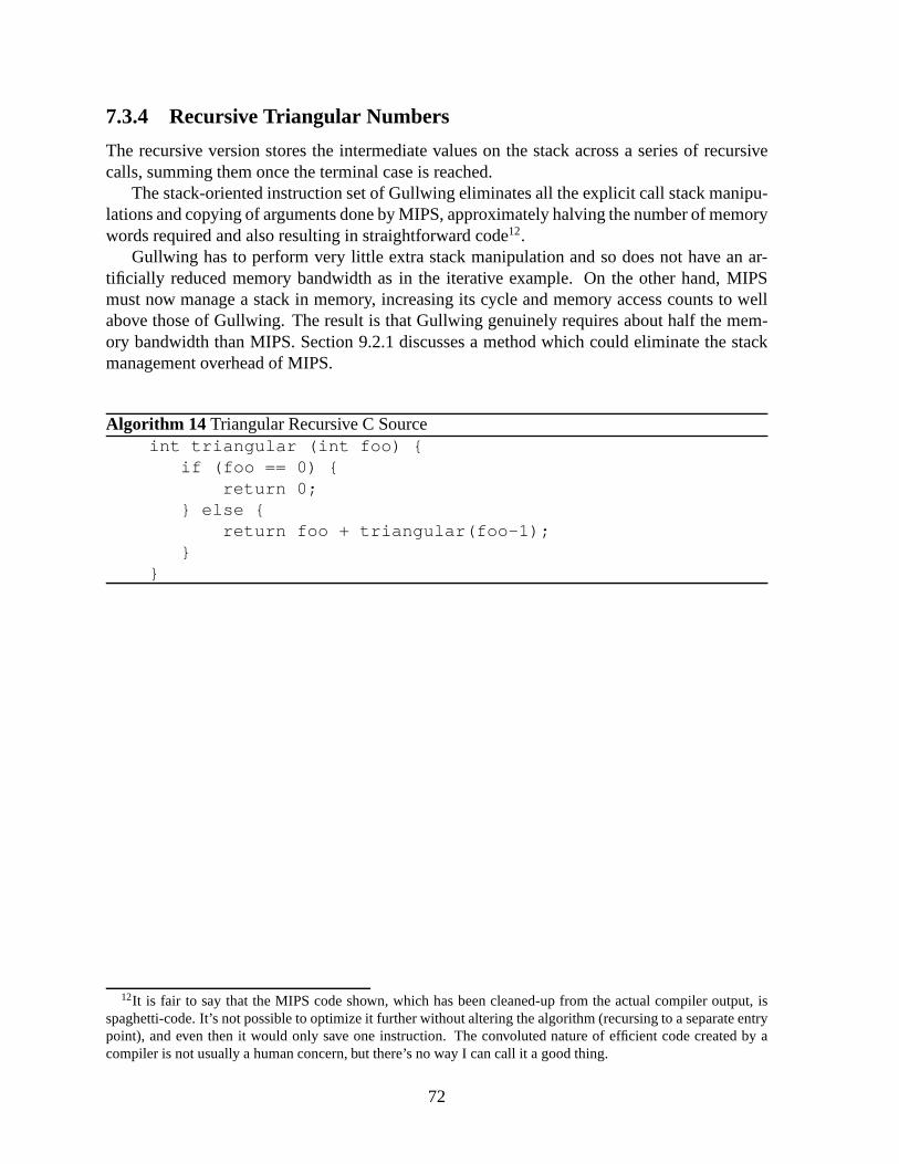
7.3.4 Recursive Triangular Numbers
The recursive version stores the intermediate values on thestack across a series of recursivecalls, summing them once the terminal case is reached.
The stack-oriented instruction set of Gullwing eliminatesall the explicit call stack manipu-lations and copying of arguments done by MIPS, approximately halving the number of memorywords required and also resulting in straightforward code12.
Gullwing has to perform very little extra stack manipulation and so does not have an ar-tificially reduced memory bandwidth as in the iterative example. On the other hand, MIPSmust now manage a stack in memory, increasing its cycle and memory access counts to wellabove those of Gullwing. The result is that Gullwing genuinely requires about half the mem-ory bandwidth than MIPS. Section 9.2.1 discusses a method which could eliminate the stackmanagement overhead of MIPS.
Algorithm 14 Triangular Recursive C Sourceint triangular (int foo) {
if (foo == 0) {return 0;
} else {return foo + triangular(foo-1);
}}
12It is fair to say that the MIPS code shown, which has been cleaned-up from the actual compiler output, isspaghetti-code. It’s not possible to optimize it further without altering the algorithm (recursing to a separate entrypoint), and even then it would only save one instruction. Theconvoluted nature of efficient code created by acompiler is not usually a human concern, but there’s no way I can call it a good thing.
72
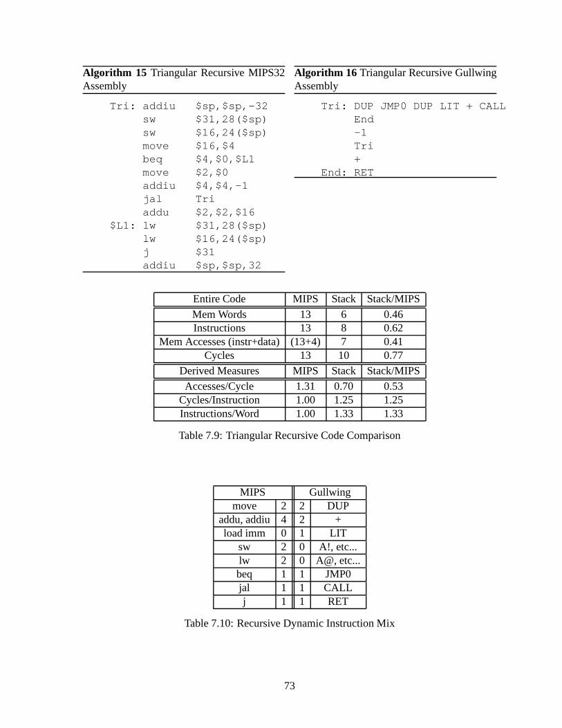
Algorithm 15 Triangular Recursive MIPS32Assembly
Tri: addiu $sp,$sp,-32sw $31,28($sp)sw $16,24($sp)move $16,$4beq $4,$0,$L1move $2,$0addiu $4,$4,-1jal Triaddu $2,$2,$16
$L1: lw $31,28($sp)lw $16,24($sp)j $31addiu $sp,$sp,32
Algorithm 16 Triangular Recursive GullwingAssembly
Tri: DUP JMP0 DUP LIT + CALLEnd-1Tri+
End: RET
Entire Code MIPS Stack Stack/MIPS
Mem Words 13 6 0.46Instructions 13 8 0.62
Mem Accesses (instr+data)(13+4) 7 0.41Cycles 13 10 0.77
Derived Measures MIPS Stack Stack/MIPS
Accesses/Cycle 1.31 0.70 0.53Cycles/Instruction 1.00 1.25 1.25Instructions/Word 1.00 1.33 1.33
Table 7.9: Triangular Recursive Code Comparison
MIPS Gullwingmove 2 2 DUP
addu, addiu 4 2 +load imm 0 1 LIT
sw 2 0 A!, etc...lw 2 0 A@, etc...beq 1 1 JMP0jal 1 1 CALLj 1 1 RET
Table 7.10: Recursive Dynamic Instruction Mix
73

7.3.5 Tail-recursive Triangular Numbers
Expressing the recursive algorithm in a tail-recursive form reuses the parameters across calls,reducing the data stack depth to that of the iterative case, and provides the opportunity toeliminate the tail call.
The advantage of this representation is that the tail call istrivially eliminated from theGullwing code by replacing theCALL instruction with aJMPand eliminating the followingRET instruction. This eliminates the accumulation of return addresses from the return stack.Optimizing the MIPS code in the same manner yields the initial iterative code. The tail of theGullwing code is not counted since it executes only once.
Expressing the algorithm in a tail-recursive form brings itcloser to the iterative case andso some of the stack manipulation overhead reappears in the Gullwing code. However, thememory bandwidth remains lower than MIPS as in the recursivecase.
Algorithm 17 Triangular Tail-Recursive C Sourceint triangular (int foo, int acc) {
if (foo == 0){return acc;
} else {acc += foo;foo -= 1;return triangular(foo,acc);
}}
74

Algorithm 18 Triangular Tail-RecursiveMIPS32 Assembly
Tri: addiu $sp,$sp,-32sw $31,24($sp)beq $4,$0,$L1addu $5,$5,$4jal Triaddiu $4,$4,-1
$L1:lw $31,24($sp)j $31addiu $sp,$sp,32
Algorithm 19 Triangular Tail-Recursive Gull-wing Assembly
Tri: OVER JMP0 OVER + >REndLIT + R> CALL-1TriRET
End: >R DROP R> RET
Main Body MIPS Stack Stack/MIPS
Mem Words 9 6 0.67Instructions 9 10 1.11
Mem Accesses (instr+data)(9+2) 7 0.64Cycles 9 12 1.33
Derived Measures MIPS Stack Stack/MIPS
Accesses/Cycle 1.22 0.58 0.48Cycles/Instruction 1.00 1.20 1.20Instructions/Word 1.00 1.67 1.67
Table 7.11: Triangular Tail-Recursive Code Comparison
MIPS Gullwingmove 0 4 DUP, OVER, >R, R>
addu, addiu 4 2 +load imm 0 1 LIT
sw 1 0 A!, etc...lw 1 0 A@, etc...beq 1 1 JMP0jal 1 1 CALLj 1 1 RET
Table 7.12: Tail-Recursive Dynamic Instruction Mix
75
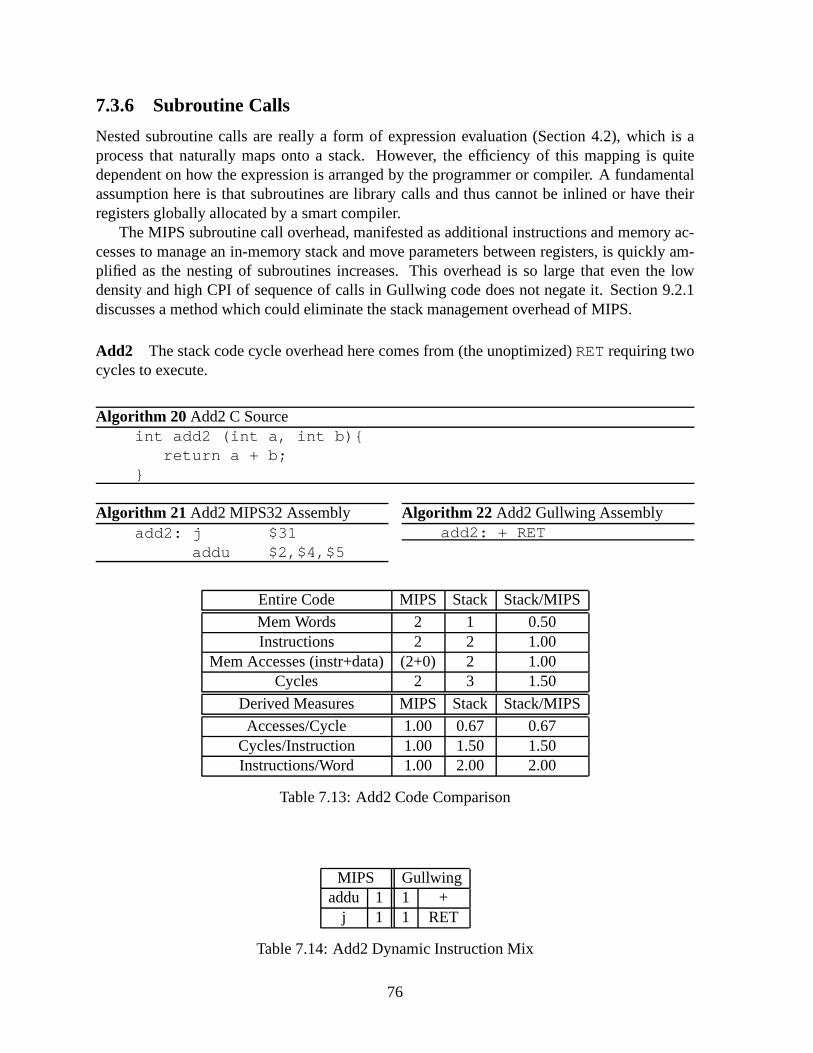
7.3.6 Subroutine Calls
Nested subroutine calls are really a form of expression evaluation (Section 4.2), which is aprocess that naturally maps onto a stack. However, the efficiency of this mapping is quitedependent on how the expression is arranged by the programmer or compiler. A fundamentalassumption here is that subroutines are library calls and thus cannot be inlined or have theirregisters globally allocated by a smart compiler.
The MIPS subroutine call overhead, manifested as additional instructions and memory ac-cesses to manage an in-memory stack and move parameters between registers, is quickly am-plified as the nesting of subroutines increases. This overhead is so large that even the lowdensity and high CPI of sequence of calls in Gullwing code does not negate it. Section 9.2.1discusses a method which could eliminate the stack management overhead of MIPS.
Add2 The stack code cycle overhead here comes from (the unoptimized)RETrequiring twocycles to execute.
Algorithm 20 Add2 C Sourceint add2 (int a, int b){
return a + b;}
Algorithm 21 Add2 MIPS32 Assemblyadd2: j $31
addu $2,$4,$5
Algorithm 22 Add2 Gullwing Assemblyadd2: + RET
Entire Code MIPS Stack Stack/MIPS
Mem Words 2 1 0.50Instructions 2 2 1.00
Mem Accesses (instr+data)(2+0) 2 1.00Cycles 2 3 1.50
Derived Measures MIPS Stack Stack/MIPS
Accesses/Cycle 1.00 0.67 0.67Cycles/Instruction 1.00 1.50 1.50Instructions/Word 1.00 2.00 2.00
Table 7.13: Add2 Code Comparison
MIPS Gullwingaddu 1 1 +
j 1 1 RET
Table 7.14: Add2 Dynamic Instruction Mix
76
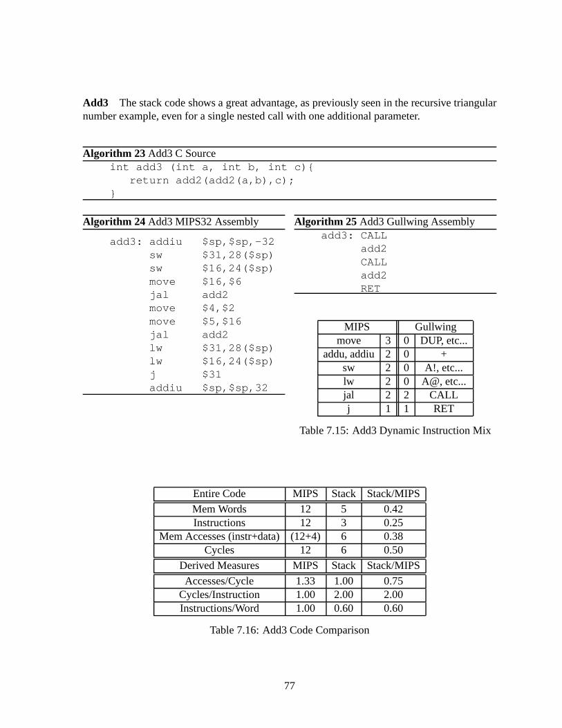
Add3 The stack code shows a great advantage, as previously seen inthe recursive triangularnumber example, even for a single nested call with one additional parameter.
Algorithm 23 Add3 C Sourceint add3 (int a, int b, int c){
return add2(add2(a,b),c);}
Algorithm 24 Add3 MIPS32 Assembly
add3: addiu $sp,$sp,-32sw $31,28($sp)sw $16,24($sp)move $16,$6jal add2move $4,$2move $5,$16jal add2lw $31,28($sp)lw $16,24($sp)j $31addiu $sp,$sp,32
Algorithm 25 Add3 Gullwing Assemblyadd3: CALL
add2CALLadd2RET
MIPS Gullwingmove 3 0 DUP, etc...
addu, addiu 2 0 +sw 2 0 A!, etc...lw 2 0 A@, etc...jal 2 2 CALLj 1 1 RET
Table 7.15: Add3 Dynamic Instruction Mix
Entire Code MIPS Stack Stack/MIPS
Mem Words 12 5 0.42Instructions 12 3 0.25
Mem Accesses (instr+data)(12+4) 6 0.38Cycles 12 6 0.50
Derived Measures MIPS Stack Stack/MIPS
Accesses/Cycle 1.33 1.00 0.75Cycles/Instruction 1.00 2.00 2.00Instructions/Word 1.00 0.60 0.60
Table 7.16: Add3 Code Comparison
77

Add4 This more complex example requires some stack manipulation. Nonetheless, its per-formance is still far better than the corresponding MIPS code.
Algorithm 26 Add4 C Sourceint add4 (int a, int b, int c, int d){
return add2(add2(a,b),add2(c,d));}
Algorithm 27 Add4 MIPS32 Assembly
add4: addiu $sp,$sp,-40sw $31,36($sp)sw $18,32($sp)sw $17,28($sp)sw $16,24($sp)move $16,$6move $17,$7jal add2move $18,$2move $4,$16move $5,$17jal add2move $4,$18move $5,$2jal add2lw $31,36($sp)lw $18,32($sp)lw $17,28($sp)lw $16,24($sp)j $31addiu $sp,$sp,40
Algorithm 28 Add4 Gullwing Assemblyadd4: CALL
add2>R CALLadd2R> CALLadd2RET
MIPS Gullwingmove 7 2 >R, R>addiu 2 0 +sw 4 0 A!, etc...lw 4 0 A@, etc...jal 3 3 CALLj 1 1 RET
Table 7.17: Add4 Dynamic Instruction Mix
Entire Code MIPS Stack Stack/MIPS
Mem Words 21 7 0.33Instructions 21 6 0.29
Mem Accesses (instr+data)(21+8) 8 0.28Cycles 21 10 0.48
Derived Measures MIPS Stack Stack/MIPS
Accesses/Cycle 1.38 0.80 0.56Cycles/Instruction 1.00 1.67 1.67Instructions/Word 1.00 0.86 0.86
Table 7.18: Add4 Code Comparison
78

7.4 Pipelining
The unpipelined view of the Gullwing processor presented inChapter 6 shows a simple com-puter with a number of components comparable to the DLX processor of Hennessy & Pat-terson. However, the cycle time of Gullwing as shown must be greater than that of the DLXsimply because an instruction cycle includes the full path from the Instruction Shift Register(ISR), through the (implicit) decoding logic, to the controlled units such as the ALU.
Pipelining Gullwing would overlap the decoding and executing of an instruction and reducethe cycle time to that of the slowest stage, which is usually the adder in the ALU. I’ll show thischange in the same manner as Koopman [Koo90], as a transformation of the well-known DLXpipeline, but in much more detail. The resulting Gullwing pipeline has a structure that impliesa comparable cycle time to the DLX pipeline.
7.4.1 Transforming the DLX Pipeline to Gullwing
For reference, Figure 7.1 [HP02, Fig. A-3] shows the basic shape of the DLX pipeline. Eachstage contains a particular subsystem: Instruction Memory(IM), Register File (Reg), Arith-metic and Logic Unit (ALU), and Data Memory (DM). These stages are commonly referredto as the Instruction Fetch (IF ), Instruction Decode (ID ), Execute (EX), Memory (MEM), andWrite-Back (WB) stages. Stages are separated by pipeline registers. The Register file is simul-taneously read in theID stage and written in theWBstage.
IM Reg
ALU DM Reg
IF ID EX MEM WB
Figure 7.1: DLX Pipeline Block Diagram
The pipelining of the Gullwing processor can be explained byexchanging the subsystemsin the DLX pipelining with those of Gullwing and following the implications.
The first change is that Gullwing has a single memory bus for instructions and data. Thisremoves the distinction between IM and DM. Since theIF stage fetches an instruction everycycle, this implies a structural hazard for every data access. However, the zero-operand instruc-tion format of Gullwing means that several instructions canbe packed as a group into a singlememory word (Section 6.2.7). This reduces the occurrence ofthe structural hazard to between2 and 4 percent of executed instructions (PC@ count in Appendix B.2.2). Furthermore, the endof a group of instructions is explicitly marked by the inclusion of a PC@ (PC Fetch) instructionwhich fetches the next group of instructions in parallel with the current instruction if possible.Combined, these two features accomplish the function of theIF stage and effectively dividesit betweenMEM, where the instructions are fetched, andID , where they are held and decoded.
79

The second change is the replacement of the register file witha stack, which has the dis-advantage of forcing a RAW (Read-After-Write) dependency between all instructions. Thismeans that an instruction inID must wait for the previous instruction inEX to reachWBbeforebeing able to continue. However, a stack has the advantage ofhaving its inputs and outputsimmediately available, without having to decode addresses13. This effectively makes theminto registers equivalent to theID/EX andEX/MEMpipeline registers connected to the ALU.Thus the stack can be moved out ofID and placed intoEX without any speed penalty. Thiseliminates theWBstage and simplifiesID .
The third change is the use of direct addressing. The DLX processor uses displacementaddressing to simulate a number of other addressing modes. This requires the ALU to computean address for each load or store instruction, forcingEX to precedeMEM. Direct addressingremoves this dependency and so both stages can now operate inparallel. SinceMEMalreadycontains the incrementer for the Program Counter (brought over from IF in the first transfor-mation), it can be re-used to implement post-incrementing direct addressing.
The end result of these changes results in the pipeline shownin Figure 7.2a, whereIDdecodes the instructions from the ISR, andEX andMEMexecute the instructions. Figure 7.2bshows how these stages map to the existing Gullwing functional blocks. Note that theEXandMEMstages both contain adding circuitry and so place a lower limit on the cycle time that iscomparable to that of the DLXEXstage.
The operation of the pipeline is similar to that of the DLX (Figure 7.3). Since the pipelineintroduces one stage of latency to execution, the next groupof instructions is loaded into theISR while the last instruction in the current group (5) decodes. This process is detailed in thenext section. Instructions that require two cycles to execute, such as loads, occupy theIDstage for the duration of their execution (Figure 7.4). Loads and stores must take two cyclessince they currently cannot be overlapped, but on the other hand there is no load delay slot.Overlapping loads and stores are discussed in Section 9.2.3.
ID
EX
MEM
MEM
(a) Pipeline
TOP +1 PC
A
MARALU
ISR
MEM adrdata
R
RS
DS
EX
MEM
ID
(b) Stage Details
Figure 7.2: Gullwing Pipeline Block Diagram
13Since a stack is only ever accessed sequentially, the addressing of the individual stack registers reduces to asingle-bit shift register, one bit per stack register, withno decoding required. A more aggressive design wouldfurther reduce the entire stack to a word-wide shift register.
80

Cycle (Current Instruction Word)Instruction 1 2 3 4 5 6 1
0 ID EX/MEM1 ID EX/MEM2 ID EX/MEM3 ID EX/MEM4 ID EX/MEM5 (next word loaded while 4 executes and 5 decodes) ID EX/MEM
0 ID
Figure 7.3: Gullwing Pipeline Operation
Cycle NotesInstruction 4 5 6 7
@A ID MEM @A stays in ID@A ID EX/MEM
4 ID EX/MEM5 ID
Figure 7.4: Gullwing Load/Stores Pipeline Diagram
7.4.2 Altering the ISR to Deal with the Additional Latency
The pipelining of Gullwing adds a latency of one stage to the execution of instructions. Thisaffects the use of the PC@ instruction to fetch the next groupof instructions when the currentone is exhausted (Section 6.1.3). After the last instruction in a group has finished, while thecurrent PC@ is in theEX stage, another PC@ would be inID and would enterEX just asthe ISR was reloaded by the first PC@. The spurious second PC@ would then load the ISRagain after only the first instruction from the new group had begun executing, skipping overthe remainder.
The solution to this side-effect of pipelining is to move ahead by one the insertion point ofthe PC@ instruction so that it begins executing while the actual last instruction in the groupbegins decoding and is executed just as the ISR is reloaded. Figure 7.5 shows the necessaryalterations to the original ISR (Figure 6.2). The PC@ instruction is inserted at the same time asthe rest of the ISR is loaded, in between the last and before-last instruction slots (S5 and S4).The slots are now filled-in with NOPs instead of PC@s as the instructions are shifted out.
The multiplexer between S0 and S1 is required to handle the instruction fetch overlap op-timization (Section 6.3.1). Once the penultimate instruction (originally in S4) reaches S0, the
81
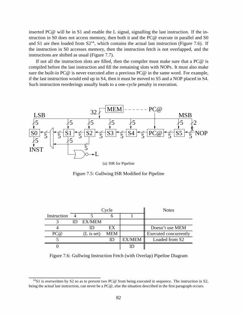
inserted PC@ will be in S1 and enable the L signal, signallingthe last instruction. If the in-struction in S0 does not access memory, then both it and the PC@ execute in parallel and S0and S1 are then loaded from S214, which contains the actual last instruction (Figure 7.6). Ifthe instruction in S0 accesses memory, then the instructionfetch is not overlapped, and theinstructions are shifted as usual (Figure 7.7).
If not all the instruction slots are filled, then the compilermust make sure that a PC@ iscompiled before the last instruction and fill the remaining slots with NOPs. It must also makesure the built-in PC@ is never executed after a previous PC@ in the same word. For example,if the last instruction would end up in S4, then it must be moved to S5 and a NOP placed in S4.Such instruction reorderings usually leads to a one-cycle penalty in execution.
5 5 5 5
32 MEM
5 5 5 5 55
5
25
55
5
55
S1 S4S2 S3 PC@ S5x
NOPS0
INSTL
LSB MSBPC@
(a) ISR for Pipeline
Figure 7.5: Gullwing ISR Modified for Pipeline
Cycle NotesInstruction 4 5 6 1
3 ID EX/MEM4 ID EX Doesn’t use MEM
PC@ (L is set) MEM Executed concurrently5 ID EX/MEM Loaded from S2
0 ID
Figure 7.6: Gullwing Instruction Fetch (with Overlap) Pipeline Diagram
14S1 is overwritten by S2 so as to prevent two PC@ from being executed in sequence. The instruction in S2,being the actual last instruction, can never be a PC@, else the situation described in the first paragraph occurs.
82

Cycle NotesInstruction 4 5 6 7 1
3 ID EX/MEM4 ID MEM Uses MEM
PC@ (L is set) ID MEM Executed sequentially5 ID EX/MEM Loaded from S1
0 ID
Figure 7.7: Gullwing Instruction Fetch (without Overlap) Pipeline Diagram
7.4.3 The Effect of Pipelining on Calls, Jumps, and the CPI
Jumps behave on a pipelined Gullwing in the same manner as on the DLX. The jump target isloaded one cycle after the jump instruction has finished executing, thus the following instruc-tion is a branch delay slot which is always executed and must be appropriately filled by thecompiler (Figure 7.8).
Also, as in the DLX, a data hazard occurs if a conditional jumpdepends on the result of theimmediately preceding instruction. However, because the stack provides only a single point forall results it makes this data hazard inevitable. As with thebranch delay slot, the compiler mustfind a way to fill this data hazard slot with useful work. One example is to fill it with a DUPinstruction which would duplicate the top of the stack before the conditional jump consumesit, thus saving its value.
In the worst case where they can only be filled with NOPs, the data hazard and branchdelay slots will add two cycles to conditional jumps, raising them to four cycles, and will addone cycle to calls, unconditional jumps, and returns, raising them to three cycles. Factoringthis overhead into the CPI data from Table 7.4 increases the CPI contribution of Subroutineinstructions to 0.450 for Extensions and 0.453 for VM, of Conditionals to 0.142 and 0.062, fora new total CPI of 1.533 and 1.481 respectively. This estimate does not take into account thesecond-order effect of the lower instruction density caused by the NOP-filled slots, which willincrease the proportion of instruction fetches.
Cycle NotesInstruction 3 4 5 6 1
2 ID EX/MEM Data Hazard SlotJMP0 ID MEM JMP0 stays in IDJMP0 ID MEM
4 ID EX/MEM Branch Delay Slot
0 ID Branch Target
Figure 7.8: Gullwing Taken Jumps or Calls Pipeline Diagram
83
7.5 Summary and Performance Comparison
In Section 7.2, the comparison of benchmark statistics revealed these facts about Gullwing,relative to DLX/MIPS:
• A greater number of literal fetches, subroutine calls, and stack permutations are executed.
• An average CPI of 1.31, which is poor compared to the average of 1.14 for a DLX.However, Gullwing is actually architecturally equivalentto a DLX without load delayslots or delayed branches, whose average CPI is 1.38.
• An average number of memory accesses per cycle of 0.667, compared to 1.421 forDLX/MIPS (Section 7.2.3).
• An average code density of only 1.2 instructions per memory word, out of a potentialmaximum of three, because most of the instruction slots remain unused.
In Section 7.3, a detailed inspection and analysis of equivalent programs which express fun-damental code features uncovered these differences between Gullwing and a generic MIPS-32computer:
• The random-access registers and explicit operands of the MIPS design are a definiteadvantage when multiple values must be maintained at once inan algorithm. Gullwingmust instead execute additional instructions to manipulate the stacks to get to the valueit needs.
• The MIPS processor must simulate a stack in software for subroutines calls and recur-sive procedures. The extra instructions to implement this stack consume more memorybandwidth and processors cycles than the equivalent Gullwing code.
• The Gullwing processor requires less memory bandwidth, often half that of MIPS, re-gardless of the number of cycles required for an algorithm.
In Section 7.4, the pipelined form of Gullwing is derived through incremental transformationof the DLX pipeline. The result is a 2-stage pipeline composed of an Instruction Decode stagefollowed by parallel Execute and Memory stages. Each stage is structurally no more complexthan any stage from the DLX pipeline, which implies that the cycle time will be similar. TheGullwing pipeline exhibits similar branch data hazard and delay slots as the DLX pipeline. Inthe worst case, these delays should increase the average CPIfrom 1.31 to 1.51.
In summary, a pipelined Gullwing processor would have a similar cycle time relative to aDLX processor. However, with the exception of subroutine calls, Gullwing usually requiresa greater number of cycles to execute the same algorithms. Italso suffers from a higher CPIdue to un-optimized load and branch delays. Therefore, to bring Gullwing up to the sameperformance as DLX, the number of executed instructions and/or the average CPI must bereduced (Sections 9.2.2 and 9.2.3).
84

Chapter 8
Improving Code Density
The density of Gullwing low-level code is very good. A 32-bitword holds six instruction slots.However, instructions that require an in-line argument such as calls, jumps, and literal fetches,also additionally use up one whole subsequent memory word1. Including one such instructionin a group, while keeping all slots filled, raises the memory usage to two words and thus halvesthe code density to three. Adding another such instruction drops the density to two, and so onuntil all six instructions require an in-line argument, with a resulting minimum code density ofsix-sevenths (∼0.86). As the number of slots in a memory word increases, the minimum codedensity increases towards unity.
This situation is unfortunately a narrow best case. It is only applicable when all instructionslots can be filled. This is true for literal fetches since they do not alter the program flow, andfor conditional jumps since they simply continue with the next instruction if the condition isnot met. Calls and unconditional jumps always load a new instruction group2. Memory isword-addressed and groups always begin execution with the first slot, therefore jumping orreturning to the instructions in the slots after a call or jump is impossible and must instead goto the next memory word after the argument. Sequences of calls thus end up wasting most ofthe available slots (Figure 8.1), bringing the minimum codedensity down to one-half.
Sequences of calls are typical of high-level code, where a procedure is primarily composedof calls to other procedures. Sequences of jumps are rare, never executed sequentially, and arenot considered further. The actual usage of the instructionslots is listed in Appendix B.1.5.The low ratio of filled instruction slots suggests that thereis room for significant improvementin code density.
CALL
CALL
CALL
Address of Subroutine 1
Address of Subroutine 2
Unreachable Slots
Address of Subroutine 3
Figure 8.1: Gullwing High-Level Code with Unavailable Slots
1Returns take their argument from the Return Stack and so require no extra memory.2As do returns.
85
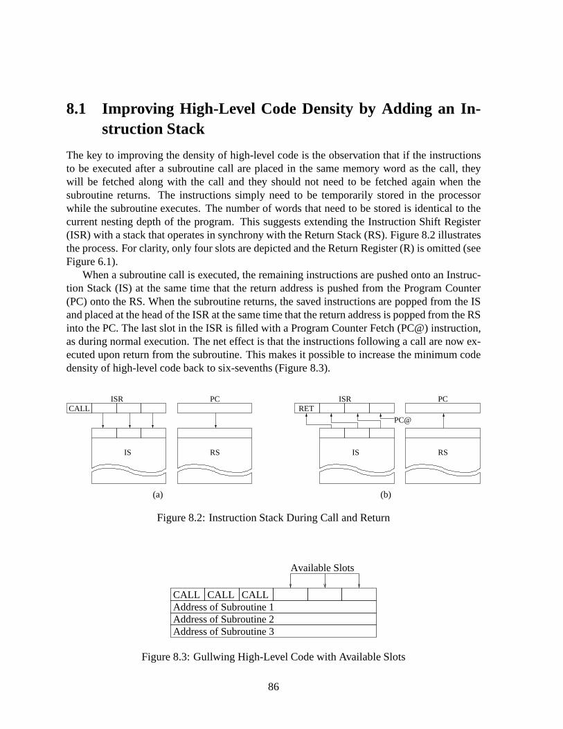
8.1 Improving High-Level Code Density by Adding an In-struction Stack
The key to improving the density of high-level code is the observation that if the instructionsto be executed after a subroutine call are placed in the same memory word as the call, theywill be fetched along with the call and they should not need tobe fetched again when thesubroutine returns. The instructions simply need to be temporarily stored in the processorwhile the subroutine executes. The number of words that needto be stored is identical to thecurrent nesting depth of the program. This suggests extending the Instruction Shift Register(ISR) with a stack that operates in synchrony with the ReturnStack (RS). Figure 8.2 illustratesthe process. For clarity, only four slots are depicted and the Return Register (R) is omitted (seeFigure 6.1).
When a subroutine call is executed, the remaining instructions are pushed onto an Instruc-tion Stack (IS) at the same time that the return address is pushed from the Program Counter(PC) onto the RS. When the subroutine returns, the saved instructions are popped from the ISand placed at the head of the ISR at the same time that the return address is popped from the RSinto the PC. The last slot in the ISR is filled with a Program Counter Fetch (PC@) instruction,as during normal execution. The net effect is that the instructions following a call are now ex-ecuted upon return from the subroutine. This makes it possible to increase the minimum codedensity of high-level code back to six-sevenths (Figure 8.3).
CALLISR
IS
PC
RS
(a)
ISR
IS
PC
RS
PC@
RET
(b)
Figure 8.2: Instruction Stack During Call and Return
Address of Subroutine 2Address of Subroutine 3
Address of Subroutine 1CALL CALL CALL
Available Slots
Figure 8.3: Gullwing High-Level Code with Available Slots
86

8.1.1 Side-Effects on Return Stack Manipulation
A consequence of the Instruction Stack (IS) is that the return addresses on the Return Stack(RS) must always be matched with the corresponding instructions stored on the IS. Any offsetbetween the Instruction and Return stacks would mean that from that point onwards all re-turns to calling procedures would execute a few random instructions before fetching the next(correct) groups of instructions!
The >R (“To R”) and R> (“R From”) instructions move data back and forth between the topof the Data Stack (TOP) and the RS. Hence they could leave the RS with a different numberof elements than the IS. To compensate, >R pushes a group of PC@ instructions onto the IS,and R> pops the IS, discarding the instructions. If >R is usedto push a return address ontothe RS, such as when the address of a function call is computedat runtime, then the nextsubroutine return will execute the stored PC@ and forcibly fetch the first instruction groupof that procedure. If R> is used to discard a return address, possibly for some kinds of errorhandling, the stored instructions for that procedure are also discarded. Figure 8.4 illustrates theprocess.
It is still possible to cause incorrect execution with the unusual code sequence ’R> >R’which would replace the stored instructions with a PC@. Thiswould skip a few instructionsupon return unless the instruction slots after the corresponding call we deliberately left unused(and thus filled with PC@ anyway). However, the need to inspect or alter the address of thecalling procedure’s caller is rather unusual. Similarly, unless there exists a means of loadingor storing the contents of the IS under program control, the RS cannot be saved to memory forthe purpose of context switching, debugging, or exception handling.
ISR
IS RS
PC@
>RTOP
(a)
ISR
IS RS
R>TOP
x x x
(b)
Figure 8.4: Instruction Stack During >R and R>
87
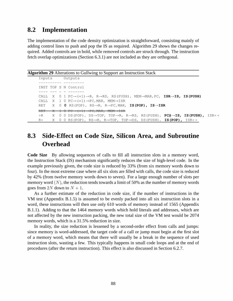
8.2 Implementation
The implementation of the code density optimization is straightforward, consisting mainly ofadding control lines to push and pop the IS as required. Algorithm 29 shows the changes re-quired. Added controls are in bold, while removed controls are struck through. The instructionfetch overlap optimizations (Section 6.3.1) are not included as they are orthogonal.
Algorithm 29 Alterations to Gullwing to Support an Instruction StackInputs Outputs---------- ---------INST TOP S N Control---- --- - - -------CALL X 0 1 PC→(+1) →R, R→RS, RS(PUSH), MEM→MAR,PC, ISR→IS, IS(PUSH)CALL X 1 0 PC→(+1) →PC,MAR, MEM→ISRRET X 0 0 RS(POP), RS→R, R→PC,MAR, IS(POP), IS→ISR
RET X 1 0 PC→(+1) →PC,MAR, MEM→ISR>R X 0 0 DS(POP), DS→TOP, TOP→R, R→RS, RS(PUSH), PC@→IS, IS(PUSH), ISR< <R> X 0 0 RS(POP), RS→R, R→TOP, TOP→DS, DS(PUSH), IS(POP), ISR< <
8.3 Side-Effect on Code Size, Silicon Area, and SubroutineOverhead
Code Size By allowing sequences of calls to fill all instruction slots in a memory word,the Instruction Stack (IS) mechanism significantly reducesthe size of high-level code. In theexample previously given, the code size is reduced by 33% (from six memory words down tofour). In the most extreme case where all six slots are filled with calls, the code size is reducedby 42% (from twelve memory words down to seven). For a large enough number of slots permemory word(N), the reduction tends towards a limit of 50% as the number of memory wordsgoes from2N down toN + 1.
As a further estimate of the reduction in code size, if the number of instructions in theVM test (Appendix B.1.5) is assumed to be evenly packed into all six instruction slots in aword, these instructions will then use only 610 words of memory instead of 1565 (AppendixB.1.1). Adding to that the 1464 memory words which hold literals and addresses, which arenot affected by the new instruction packing, the new total size of the VM test would be 2074memory words, which is a 31.5% reduction in size.
In reality, the size reduction is lessened by a second-ordereffect from calls and jumps:since memory is word-addressed, the target code of a call or jump must begin at the first slotof a memory word, which means that there will usually be a break in the sequence of usedinstruction slots, wasting a few. This typically happens insmall code loops and at the end ofprocedures (after the return instruction). This effect is also discussed in Section 6.2.7.
88
Silicon Area Adding a third stack increases the silicon area required by the processor. Theadditional area consumed by the IS is similar to that of the Return Stack since it must be of thesame depth and slightly less wide.
The breakeven point between the additional area of the IS andthe saved area in mainmemory, given a uniform word width, is when the reductionR in the original sizeS of aprogram, due to the addition of the IS mechanism, is equal to the depthD of the IS stack:S − S(1 − R) = D.
For example, ifR is taken to be the previously determined value of 31.5%, thenS needs tobe 3.17 times larger thanD for its size to be reduced by the same amount as the size of the IS.Since a stack rarely needs to be more than 32 words deep (Section 5.5),S would only need tobe equal to 102 memory words to justify the additional area ofthe IS mechanism.
For larger programs, the reduction in code size would greatly outweigh the area of the IS.The size of the main memory can thus be correspondingly reduced3. The lowered total siliconarea (processor and memory) would especially benefit embedded systems.
Subroutine Overhead The use of the IS eliminates the need to fetch the remaining instruc-tion slots after a call instruction. Algorithm 29 shows thatthe load in the eliminated secondcycle of the return instruction is no longer required because the remaining instruction slots arenow loaded from the IS during the first cycle. This reduces theoverhead of calling and return-ing from a subroutine to three cycles, down from four, and also reduces the associated memorytraffic by the same 25%.
8.3.1 The Instruction Stack as an Instruction Cache
Section 7.2.4.1 discusses how the packing of multiple instructions in a memory word makeseach memory word into a cache line of sorts. This caching effect reduces the number of sequen-tial instruction fetches within a basic block, as performedby PC@ (“PC Fetch”) instructions,leaving virtually all loading of instructions to calls and jumps.
With the addition of the Instruction Stack, multiple basic blocks, or at least fragmentsthereof, can fit into a single memory word. This extends the caching effect across basic blocksseparated by calls. The basic block fragment following a call instruction had already beenpreviously loaded and kept on the IS while the subroutine wasexecuting.
3This assumes that the stacks and main memory are implementedusing the same memory technology.
89

90

Chapter 9
Conclusions, Contributions, and FurtherWork
The first part of this thesis presented the historical origins of the first generation of stack com-puters and found that these machines were derived from Bauer’s stack principle for the alloca-tion of storage in nested subroutines, later used in the specification of ALGOL and now seen asthe call stack of C and other programming languages, and thatthe second generation of stackcomputers was based on Hamblin’s independently discoveredstack principle geared at func-tion composition instead of storage allocation. The English Electric KDF9, made commerciallyavailable around 1963, was found to stand out as the first second-generation stack computerand the only one until the NOVIX NC4016 in 1985. This gap, and the coincidence with theappearance of RISC microprocessors, accounts for the obscurity of the second generation.
The second part of this thesis built upon the first by proposing a set of criteria to distinguishfirst and second-generation stack computers. In summary, second generation stack computerskeep their stacks in the CPU instead of main memory, use the stacks for the evaluation andcomposition of functions instead of procedure storage allocation, and use simple, RISC-likeinstructions instead of complex microcoded operations. Chapter 5 then presented a rebuttal tothe influential arguments against stack architectures cited by Hennessy & Patterson and foundthat they are not applicable to second-generation stack computers due to their different designand to advances in hardware technology and compilers. The most telling finding is that somemodern processors, such as the Intel Pentium IV and the Digital Alpha AXP 21064, use a 16-deep internal stack to cache return addresses in the same manner as second-generation stackcomputers.
The third part of this thesis specified the design of a small second-generation stack ma-chine, named ’Gullwing’. The first unusual feature found wasthat the packing of multipleinstructions per memory word, made possible by the zero-operand instruction format, reducedthe number of sequential instruction fetches to between 8.3% and 9.7% of the total numberof executed instructions despite achieving an average codedensity of only 1.2 instructions permemory word. An additional simple optimization of the instruction fetch mechanism reducedthis fetching overhead by 50.6 to 77.3%, down to 4.1 to 2.2% ofthe total number of executedinstructions, effectively eliminating the need for a second memory bus dedicated to fetchinginstructions.
Chapter 7 then compared Gullwing to the DLX and MIPS processors, via some aggregate
91
benchmarks and some low-level code comparisons. In Section7.2, it was observed that 23.3to 29.2% of the executed instructions on Gullwing are stack manipulation instructions whoseactions are implicit in the three-operand instruction format of MIPS. Similarly, Gullwing mustperform 10 to 16% more immediate loads since there are no operands to hold small constants.
The average CPI of Gullwing was between 1.301 and 1.312: a penalty of 13.1 to 18.2% overDLX. However, Gullwing is architecturally equivalent to a DLX processor without delayedbranches and loads. Without these optimizations the CPI of DLX would have been 1.34 to1.41 instead: 2.1 to 8.4% worse than Gullwing.
It was also found that MIPS performed an average of 1.421 memory accesses per cycle,while Gullwing required only 0.667: a 53% reduction in memory bandwidth. For instructionfetching alone, Gullwing required 55.9% fewer memory accesses per cycle on average (0.441vs. 1.00 for MIPS). These improvements were found to originate in the packing of multipleinstructions per memory word: 71.1 to 80.9% of code basic blocks fit within a single memoryword on Gullwing.
Section 7.3 showed that Gullwing is at a disadvantage when multiple intermediate resultsare required. A comparison of iterative code demonstrated that Gullwing required 25% morememory space, 125% more instructions, 25% more memory accesses, and 150% more cycles,compared to MIPS, to execute the iterative algorithm due to the need to shuffle values on andoff the Data Stack.
On the other hand, Gullwing exhibits extremely efficient function calls. The same algo-rithm, implemented recursively on Gullwing, required 54% less memory space, 38% fewerinstructions, 59% fewer memory accesses, and 23% fewer cycles than the equivalent recur-sive MIPS code due to the elimination of the instructions required to simulate a stack in mainmemory.
When looking at pure nested subroutines, as would be the casewith precompiled libraries,Gullwing’s advantage at subroutine calls is amplified further: 58 to 67% less (code) memoryspace, 71 to 75% fewer instructions, 62 to 72% fewer memory accesses, 50 to 52% fewercycles, and a 25 to 44% reduction in memory bandwidth, despite an average CPI between 1.67and 2.00 and a code density between 0.60 and 0.86 instructions per word.
As originally specified, the Gullwing processor was not pipelined, and so its cycle timewould have exceeded that of the pipelined DLX processor. A pipelined form of Gullwing wasspecified by transforming the stages of the DLX pipeline to Gullwing’s stack architecture. Theresult is a two-stage pipeline with parallelEXandMEMstages, which has branch delay slots likeDLX, but no load delay slots and additional branch hazard slots due to the use of a stack insteadof registers. In the worst case where these slots could not beused productively, the average CPIof Gullwing would increase by 12.9 to 17.8%, to a range of 1.481 to 1.533. Assuming that theALU is the critical path of a simple pipeline, then the two-stage pipelined form of Gullwingshould have a similar cycle time to the five-stage DLX pipeline.
Finally, Chapter 8 proposed the use of a third stack to temporarily hold instructions duringsubroutine calls. This Instruction Stack would maximize the density of high-level code withmany branches and calls, reducing the overall code size by a little over 30% (up to a theoreticallimit of 50%), and would reduce the memory traffic and cycle count overhead of calling andreturning from a subroutine by 25%.
92
9.1 Contributions
This thesis makes the following contributions:
1. a historical review of first-generation stack computers which uncovers the origins of theconceptual difference between first and second-generationmachines (Chapter2);
2. a historical review of second-generation stack computers which provides a summary ofmany lesser-known and unpublished machines (Chapter 3);
3. a set of criteria to distinguish first and second-generation stack computers which expandon those given by Feldman and Retter [FR93, pp.599-604] (Chapter 4);
4. a rebuttal of the arguments against stack computers citedby Hennessy and Patterson,showing that they are applicable to the first generation of stack computers, but not thesecond (Chapter 5);
5. a register-transfer level description of Gullwing, a simple, modern second-generationstack computer, along with an optimization of its instruction fetching mechanism (Chap-ter 6);
6. an initial comparison of the execution statistics of non-numerical code on both Gullwingand MIPS (Section 7.2);
7. a detailed comparison of the behaviour of iteration, recursion, tail-recursion, and subrou-tine calls on both Gullwing and MIPS (Section 7.3);
8. the design of the Gullwing pipeline as a transformation ofthe DLX pipeline (Section7.4);
9. the proposal of an instruction stack to maximize the code density and accelerate thesubroutine returns of Gullwing (Chapter 8).
9.2 Further Work
Section 7.5 summarized some comparisons between DLX/MIPS and Gullwing. As Gullwingcurrently stands, its overall performance is lacklustre when compared to a basic MIPS pro-cessor. Although the cycle time should be similar, Gullwinglacks result forwarding betweenfunctional units, which makes its pipelining incomplete and inflates its CPI, as evidenced bythe two-cycle loads, stores, branches, and calls. The instructions of Gullwing are also simplerthan those of MIPS and thus more are required to accomplish the same task, with the excep-tion of subroutine calls, which Gullwing performs with fewer instruction, cycles, and memoryaccesses than MIPS.
This section presents some future improvements to Gullwingwhich could bring its CPIcloser to the ideal of 1.00, as well as reduce the impact of itshigher instruction count. Addi-tionally, the addition of a stack to the MIPS architecture isdiscussed, in order to grant MIPS theefficient subroutine calls of Gullwing without otherwise altering the instruction set or pipeline.
93

9.2.1 Reducing the DLX/MIPS Subroutine Call Overhead by Adding Stacks
The MIPS architecture has very inefficient subroutine callscompared to Gullwing, stemmingfrom the need to save and restore registers to a stack in memory (Section 7.3.6). Conversely,Gullwing has poor performance for iterative code because itlacks random-access registers. Acombination of both might yield the best of both worlds.
Figure 9.1 shows a conceptual modification to the MIPS register file which would createthe possibility of running stack-like code for efficient subroutine calls, while otherwise leavingthe instruction set, architecture, and pipeline unchanged. A Data Stack and a Return Stack areadded ’underneath’ some registers. The Return Stack goes under register $31 since it is wherethe current return address is normally stored by thejal (Jump And Link) instruction. TheData Stack could be placed under any other registers, but is placed here under registers $2 and$1 for illustrative purposes. Two registers are used so thattwo operands can be taken from thestack when needed. Register $0 is is of course a source of zeroes on reads and a sink on writes.
If the stacks are disabled, the register file behaves as usual, and existing code runs un-changed. When the stacks are enabled, a read from a register connected to a stack ($31, $2,and $1) pops the content of the stack into the register, making the read operation destructive,and a write to a register pushes the previous contents of the register onto the stack. The excep-tions to this behaviour are when both $2 and $1 are read together, only the contents of $2 areoverwritten by the stack, and if $1 is both read and written inthat same instruction, it is simplyoverwritten as if it had been popped, then pushed.
Given this rough sketch of stack and register interaction, Table 9.1 shows how a numberof stack computer instructions can be synthesized by suitable MIPS instructions. Small inlineconstants and branch target labels are denoted by ’$Ln’.
The stack manipulation instructions, such as DROP and OVER,should never be required.A compiler would use other registers as usual for the storageof counters and common subex-pressions, thus avoiding the stack manipulation overhead of iterative code seen in Section 7.3.3,and avoiding the RAW (Read After Write) dependency of the stack. Conversely, the stack couldbe used to hold local variables and arguments to subroutines, which would reduce or outrighteliminate the loads and stores required for nested subroutine calls on MIPS (Section 7.3.6).
Algorithm 30 shows the recursive example from Section 7.3.4implemented using stacks.Tables 9.2 and 9.3 show that, relative to the original MIPS code, the loads and stores areeliminated, the algorithm uses 38% fewer cycles, and memorybandwidth is reduced by 24%.
A similar register and stack mechanism was proposed by Richard L. Sites [Sit78], with theprimary intent of simplifying expression evaluation. He observed that a stack placed under oneof the registers allowed the evaluation of an expression using fewer actual registers. In currentsystems, this could make possible smaller register files, orgive a compiler more room to doregister allocation.
$2...
DSRS
$31 $30 $1 $0
Figure 9.1: MIPS Register File with Stacks
94

Stack MIPS Stack MIPS
CALL jal $Ln NOT xor $1,$1,-1RET j $31 AND and $1,$1,$2JMP b $Ln + add $1,$1,$2JMP0 beq $1,$0,$Ln DROP add $0,$0,$1LIT addi $1,$0,$Ln SWAP add $1,$2,$0@ lw $1,($30) PUSH add $1,$30,$0! sw $1,($30) POP add $30,$1,$0
Table 9.1: Synthesized Stack Operations on MIPS with Stacks
Algorithm 30 Triangular Recursive MIPS32Assembly with Stacks Added
Tri: add $30,$1,$0 // POPbeq $30,$0,$L1 // JMP0add $1,$30,$0 // PUSHaddi $1,$0,-1 // LITjal Tri // CALLadd $1,$1,$2 // +add $1,$1,$2 // +
$L1: j $31 // RET
Instructions Without With
move 2 0addu, addiu 4 5
sw 2 0lw 2 0beq 1 1jal 1 1j 1 1
Table 9.2: Recursive MIPS32 Instruction Dis-tribution With and Without Stacks
Entire Code Without With With/Without
Mem Words 13 8 0.62Instructions 13 8 0.62
Mem Accesses (instr+data)(13+4) 8 0.62Cycles 13 8 0.62
Derived Measures Without With With/Without
Accesses/Cycle 1.31 1.00 0.76Cycles/Instruction 1.00 1.00 1.00Instructions/Word 1.00 1.00 1.00
Table 9.3: Triangular Recursive MIPS32 Code Comparison With and Without Stacks
95
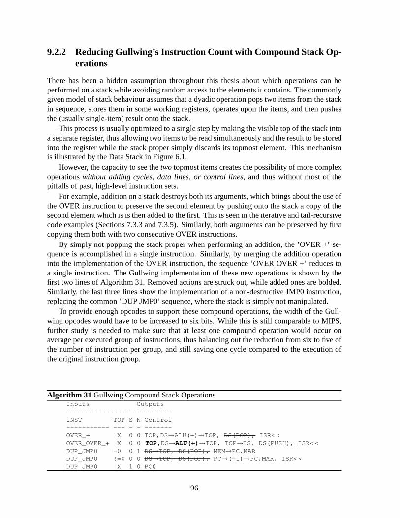
9.2.2 Reducing Gullwing’s Instruction Count with CompoundStack Op-erations
There has been a hidden assumption throughout this thesis about which operations can beperformed on a stack while avoiding random access to the elements it contains. The commonlygiven model of stack behaviour assumes that a dyadic operation pops two items from the stackin sequence, stores them in some working registers, operates upon the items, and then pushesthe (usually single-item) result onto the stack.
This process is usually optimized to a single step by making the visible top of the stack intoa separate register, thus allowing two items to be read simultaneously and the result to be storedinto the register while the stack proper simply discards itstopmost element. This mechanismis illustrated by the Data Stack in Figure 6.1.
However, the capacity to see thetwo topmost items creates the possibility of more complexoperationswithout adding cycles, data lines, or control lines, and thus without most of thepitfalls of past, high-level instruction sets.
For example, addition on a stack destroys both its arguments, which brings about the use ofthe OVER instruction to preserve the second element by pushing onto the stack a copy of thesecond element which is is then added to the first. This is seenin the iterative and tail-recursivecode examples (Sections 7.3.3 and 7.3.5). Similarly, both arguments can be preserved by firstcopying them both with two consecutive OVER instructions.
By simply not popping the stack proper when performing an addition, the ’OVER +’ se-quence is accomplished in a single instruction. Similarly,by merging the addition operationinto the implementation of the OVER instruction, the sequence ’OVER OVER +’ reduces toa single instruction. The Gullwing implementation of thesenew operations is shown by thefirst two lines of Algorithm 31. Removed actions are struck out, while added ones are bolded.Similarly, the last three lines show the implementation of anon-destructive JMP0 instruction,replacing the common ’DUP JMP0’ sequence, where the stack issimply not manipulated.
To provide enough opcodes to support these compound operations, the width of the Gull-wing opcodes would have to be increased to six bits. While this is still comparable to MIPS,further study is needed to make sure that at least one compound operation would occur onaverage per executed group of instructions, thus balancingout the reduction from six to five ofthe number of instruction per group, and still saving one cycle compared to the execution ofthe original instruction group.
Algorithm 31 Gullwing Compound Stack OperationsInputs Outputs----------------- ---------INST TOP S N Control----------- --- - - -------OVER_+ X 0 0 TOP,DS→ALU(+) →TOP, DS(POP), ISR< <OVER_OVER_+ X 0 0TOP,DS→ALU(+)→TOP, TOP→DS, DS(PUSH), ISR< <DUP_JMP0 =0 0 1 DS→TOP, DS(POP), MEM→PC,MARDUP_JMP0 !=0 0 0 DS→TOP, DS(POP), PC→(+1) →PC,MAR, ISR< <DUP_JMP0 X 1 0 PC@
96

9.2.3 Reducing Gullwing’s CPI by Executing Multiple Instructions usingGeneralized Instruction Folding
Section 6.3.1 describes a change to the decoding of instructions which allows the overlappingof the execution of the PC@ (’PC Fetch’) instruction with that of any instruction that does notaccess memory, retiring both instructions at once. This mechanism could be generalized to agreater number of pairs of instructions.
For example, the ’OVER +’ and ’DUP JMP0’ compound operationsdescribed in Section9.2.2 could be implemented, without adding new opcodes, by decoding both the current andthe next instruction and then shifting them both out. This feature widens the instruction inputto the decoder and might present a time or area penalty since the instruction encoding is dense1.
Loads and stores can especially benefit from the decoding of two instructions at once.Instead of holding steady for two cycles the instruction input to the decoder while the load orstore executes its two phases, the first phase can be executedwhen the instruction enters thefirst part of the two-instruction window of the improved decoder, and the second phase whenthe instruction enters the second part of the window. Algorithm 32 shows how the instructionsequence ’DROP A@+ R@+ XOR RET’2 would be executed: The first line shows the firstphase of A@+ folded with the execution of DROP. The second line contains the overlappedsecond phase of A@+ and first phase of R@+. The third line does not overlap the execution ofXOR with the second phase of @R+ since the load must complete before XOR can operate onthe loaded value. Finally, the fourth and fifth lines show howXOR and RET are overlapped.
The execution of this five-instruction code sequence now takes five cycles instead of eight.Its CPI went from 1.60 to 1.00. The number of memory accesses per cycle increased from 0.75to 1.00. The performance is now on par with that of non-branching code on MIPS.
The data dependency of the ’@R+ XOR’ sequence could be avoided by enabling the ALUto use MEM as an input. Similarly, the ’LIT JMP0’ sequence could be overlapped if an ad-ditional zero-detect circuit was connected to MEM, and ’>A @A’ would benefit from a directpath between TOP and MAR. This forwarding of data, equivalent to the result forwarding ofthe MIPS processor, does add multiplexers in the data path and thus the cycle time to cyclecount trade-off should be considered carefully.
Algorithm 32 Example Gullwing Instruction Sequence Using Generalized FoldingInputs Outputs-------------- ---------S0 S1 TOP S N Control---- --- --- - - -------DROP @A+ X 0 0 DS→TOP, DS(POP), A →MAR,(+1) →A, ISR< <@A+ @R+ X 0 0 MEM→TOP, TOP→DS, DS(PUSH), R →MAR,(+1) →R, ISR< <@R+ XOR X 0 0 MEM→TOP, TOP→DS, DS(PUSH), PC →MAR, ISR< <XOR RET X 0 0 TOP,DS→ALU(XOR)→TOP, DS(POP), \\ cont. next line
RS(POP), RS→R, R→PC,MAR, ISR< <RET PC@ X 0 0 PC→(+1) →PC,MAR, MEM→ISR
1By comparison, MIPS R-type instructions use a total of twelve opcode bits, but do not encode212 uniqueinstructions. The encoding must thus be sparse and simple todecode.
2A simple hypothetical comparison routine based on COMPARE_STRING from Appendix A.1.3.
97

98

Appendix A
Gullwing Benchmarks Source
The appendix provides the source code for the benchmarks described in Section 7.1.
A.1 Flight Language Kernel
The Flight language kernel defines the basic functions needed to define, lookup, and executefunctions. These basic functions enable the system to extend itself without external software.The kernel is written in Gullwing machine language, described here symbolically. The mainloop of the kernel is described in Section A.1.9. I have addedcomments, but they are notpresent in the actual source code.
A.1.1 Internal Variables and Memory Map
These variables contain the state of the kernel. Each is a single memory word. They define theboundaries of areas of memory illustrated in Figure A.1.
HERE Contains the address of the memory location that is the current target for compilation.
HERE_NEXT Contains the address of the next memory word where code is to be compiled.
SLOT Contains the bitmask which defines the current available instruction slot in the mem-ory word pointed-to by HERE.
THERE Contains the address of the top of the function name dictionary. Also the pointer tothe bottom of the input buffer.
NAME_END Contains the address of the end of the function name dictionary. It is used todetect the failure of a dictionary search.
99
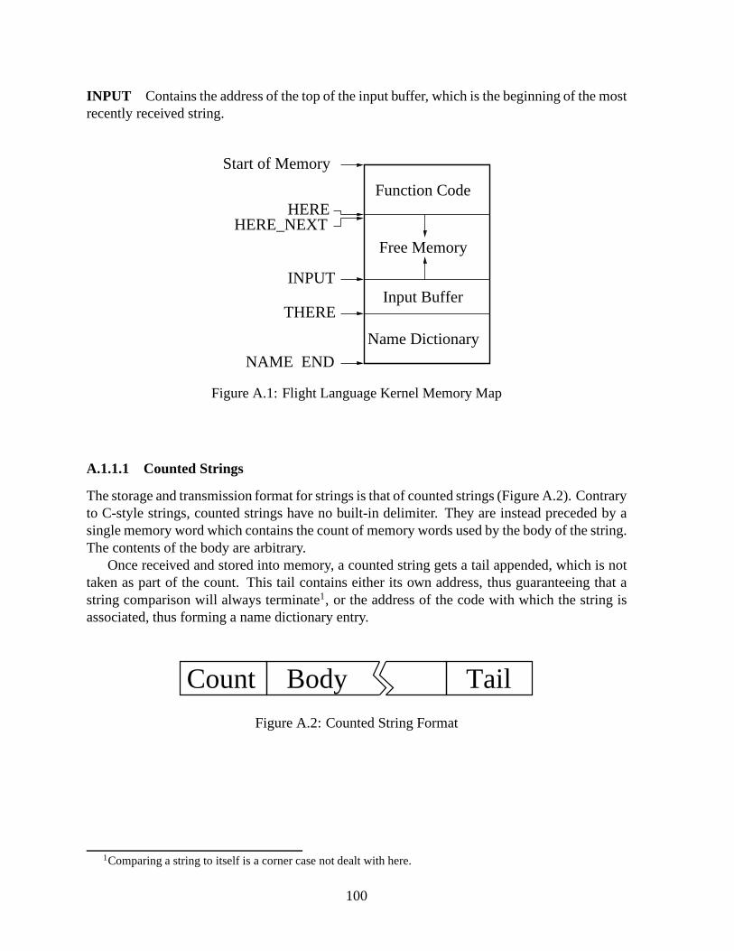
INPUT Contains the address of the top of the input buffer, which is the beginning of the mostrecently received string.
Free Memory
Input Buffer
Name Dictionary
Function Code
INPUT
THERE
NAME_END
HEREHERE_NEXT
Start of Memory
Figure A.1: Flight Language Kernel Memory Map
A.1.1.1 Counted Strings
The storage and transmission format for strings is that of counted strings (Figure A.2). Contraryto C-style strings, counted strings have no built-in delimiter. They are instead preceded by asingle memory word which contains the count of memory words used by the body of the string.The contents of the body are arbitrary.
Once received and stored into memory, a counted string gets atail appended, which is nottaken as part of the count. This tail contains either its own address, thus guaranteeing that astring comparison will always terminate1, or the address of the code with which the string isassociated, thus forming a name dictionary entry.
Count TailBody
Figure A.2: Counted String Format
1Comparing a string to itself is a corner case not dealt with here.
100

A.1.2 Utility Functions
These are small functions which synthesize operations not implemented by the Gullwing pro-cessor. They are shown here as subroutines but are normally compiled in-line due to theirsize.
MINUS Negates the number on the top of the Data Stack before adding it to the next number.
NOT LIT 1 PLUS PLUS RET
OR Performs the bit-wise logical OR of the top two numbers on theData Stack.
OVER NOT AND XOR RET
A.1.3 String Functions
These are the lowest level input buffer manipulation routines. The input buffer behaves likea simple stack of counted strings. The top of stack pointer isINPUT, the bottom pointer isTHERE.
STRING_TAIL Returns the address of the tail of a string. Takes the head address of thestring. The tail contains an address used for referencing code or terminating string compar-isons.
//get string length and skip it>A A@+//string tail addressA> + RET
PUSH_STRING Alters INPUT to allocate the space for a counted string. Setsthe tail of thestring to point to its own address. Takes the length of the string from the Data Stack.
// account for string count and address tailDUP LIT 1 + NOT// adjust INPUTLIT [address of INPUT] >A A@ + DUP A!// store string length count at [INPUT]>A A!LIT [address of INPUT] >A A@CALL STRING_TAILDUP >A A! RET
101

POP_STRING Alters INPUT to discard the most recently SCAN’ed string.
LIT [address of INPUT] >A A@CALL STRING_TAIL// point to head of next stringLIT 1 +LIT [address of INPUT] >A A! RET
For comparison, this alternate version keeps a copy of the address of INPUT on the stack. Itavoids a literal fetch and a function call, but is harder to follow. An optimizing compiler mightgenerate code like this.
LIT [address of INPUT] DUP >R// get [INPUT]>A A@ DUP// get string length>A A@// add length+2 to [INPUT] to point to next string+ LIT 2 +// update INPUTR> >A A! RET
COMPARE_STRINGS Takes the head address of two strings. Returns the addresses(in thesame order) of the first non-matching pair of symbols. Note that the practise of tailling eachstring with the address of the tail guarantees that the comparison will terminate (at the tail).
>A >RLOOP:R@+ A@+ XORJMP0 LOOPLIT -1 R> +LIT -1 A> + RET
A.1.4 Input Functions
These functions read in counted strings from the outside world.
READ1 Presumed here is that READ1 always returns a memory word. Implementationdepends on interface to outside world. Here I assume a memoryport for illustration purposes.
// read in one memory wordLIT [address of input port] >A A@ RET
102

SCAN_STRING Reads a string into a pushed string entry.
// get string length and prepLIT [address of INPUT] >A A@ >R R@+SCAN_STRING_LOOP:// READ1 uses ACALL READ1 R!+LIT -1 + DUP JMP0 DONEJMP SCAN_STRING_LOOP// storage address should be equal to (INPUT)+length+1 nowDONE:// store address of end of string in itself for LOOK terminati onDROP R> DUP >A A! RET
SCAN Reads in a string from the outside world. Input is a counted string, where the firstmemory word contains the following number of memory words used by the string, regardlessof symbol encoding. Always reads in the string. There is no check.
The location after the string is kept free to hold its own address (which is [THERE]) as atermination marker for LOOK, or an actual code address should it become a name entry.
To see if there is enough free space, the sender of the string can check in advance if theresult of "INPUT HERE -" is greater than the string length. The check depends on the fact thatHERE points to an address that begins at 0 and increments, while INPUT points to a locationthat begins at THERE and decrements. THERE begins at the end of memory and decrementstowards zero. If they meet, then there is no more free memory.Thus if the start address islesser than the one HERE points at, there is no room for the string (or for anything else at all!).
CALL READ1CALL PUSH_STRINGJMP SCAN_STRING
A.1.5 Name Lookup
LOOK Searches the name dictionary for the topmost string in the input buffer. Returns theaddress of the code associated with the name or NAME_END if nomatch. No error checkingother than for the end of the dictionary.
// address of latest name entry stringLIT [address of THERE] >A A@ LIT 1 + DUPLOOP:// address of topmost SCANed stringLIT [address of INPUT] >A A@CALL COMPARE_STRINGSLIT [address of INPUT] >A A@CALL STRING_TAILXOR JMP0 MATCH
103

// uses the DUPed name entry addressDROPCALL STRING_TAIL// point to start of next name entryLIT 1 +// are we at end of name dict?DUP LIT [address of NAME_END] >A A@ XOR JMP0 NOMATCHDUP JMP LOOPMATCH:// return code address for name entry>A DROP A@ RETNOMATCH:// return address of end of dictDROP LIT [address of NAME_END] >A A@ RET
A.1.6 Function Definition Functions
These functions create new name dictionary entries and setup the compilation of the code thatwill be associated with the new name.
FIRST_SLOT Begin compiling at zeroth instruction slot.
LIT [address of SLOT] >ALIT [mask for slot 0] A! RET
LAST_SLOT Setup at fifth instruction slot, so the next compilation willoccur at the zerothslot.
LIT [address of SLOT] >ALIT [mask for slot 5] A! RET
NULL_SLOT Null instruction slot mask. Denotes that HERE is empty.
LIT [address of SLOT] >ALIT [mask for null slot] A! RET
ALIGN Makes HERE point to the next free location, so we don’t point aname at the tailend of the previous procedure or clobber literals. Make HERE_NEXT point to the followinglocation. Mark HERE as empty with NULL_SLOT.
LIT [address of HERE_NEXT] >A A@// zero out location, and increment addressDUP >R LIT 0 R!+// update HERE_NEXTR> A!
104

// update HERELIT [address of HERE] >A A!JMP NULL_SLOT
NEXT_SLOT Point to first slot if HERE is empty (NULL_SLOT), else point tonext freeslot at HERE, else ALIGN.
// get slot maskLIT [address of SLOT] >A A@LIT [null slot mask] OVER XOR JMP0 HEREEMPTYLIT [fifth slot mask] OVER XOR JMP0 HEREFULL// next 5-bit slot2* 2* 2* 2* 2* A! RETHEREFULL:DROP CALL ALIGN JMP FIRST_SLOTHEREEMPTY:DROP JMP FIRST_SLOT
DEFN_AS Takes the ALIGNed address of a code entry (usually [HERE]) and the address ofa SCANed string (from INPUT) and converts it to a name entry. Updates THERE.
The name string must be the only one in the input buffer stack as it is converted in place,so INPUT must be pointing to it and its tail must be at THERE. Because of this, INPUT doesnot need to be changed.
// store address in [THERE]LIT [address of THERE] >A A@ >A A!// get string start addressLIT [address of INPUT] >A A@// move to first free location before itLIT -1 +LIT [address of THERE] >A A! RET
NEW_WORD Returns an aligned address at which to compile code.
CALL ALIGN// get [HERE]LIT [address of HERE] >A A@ RET
DEFN Defines a name entry for the current code location.gate
CALL NEW_WORDJMP DEFN_AS
105

A.1.7 Compilation Functions
These functions enable the kernel to compile the Gullwing opcodes. By convention, functionsthat compile a Gullwing opcode or inline another function have parentheses around their name.
COMPILE_INIT Initialize HERE, HERE_NEXT, and SLOT for compilation.
LIT [address of HERE] >ALIT [initial compilation address] A!+ A>LIT [address of HERE_NEXT] >A A!LIT [address of SLOT] >ALIT [mask for slot 5] A!LIT [address of HERE] >A A@ >A// Zero out memory to compile toLIT 0 A! RET
COMPILE_OPCODE Takes an opcode (in slot 0) and compiles it at the next empty HERE/SLOTlocation. Assumes the current slot is full. Leaves SLOT pointing to next full slot.
This function fails for the PC@ instruction, since its opcode is all zeroes. It shouldn’t benecessary to compile it explicitly, as that’s what ALIGN does when it zeroes the memory word.Note the addition instead of logical OR at the end. We can do this since empty slots are filledwith PC@ opcodes (zeroes).
CALL NEXT_SLOT// get slot mask and invert>R LIT [address of SLOT] >A A@ ~//place opcode on topR>// slot 0OVER OVER AND JMP0 COMPILE// shift opcode by one slot2* 2* 2* 2* 2*// slot 1OVER OVER AND JMP0 COMPILE2* 2* 2* 2* 2*// slot 2OVER OVER AND JMP0 COMPILE2* 2* 2* 2* 2*// slot 3OVER OVER AND JMP0 COMPILE2* 2* 2* 2* 2*// slot 4OVER OVER AND JMP0 COMPILE2* 2* 2* 2* 2* gate// then we * have * to be in slot 5
106

COMPILE:LIT [address of HERE] >A A@// compile opcode, drop mask, return>A A@ + A! DROP RET
COMPILE_LITERAL Takes a procedure address or literal (for CALL, JMP, JMP0, orLIT)and compiles it at HERE_NEXT. Increments HERE_NEXT.
LIT [address of HERE_NEXT] >A A@gate// store address/literal and increment>A A!+// update HERE_NEXTA> LIT [address of HERE_NEXT] >A A! RET
CMPC, (CALL) Takes the address of a procedure an compiles a call to it. Thenaligns to thenext free word since later slots in current word will never execute.
LIT [opcode for CALL]CALL COMPILE_OPCODECALL COMPILE_LITERALJMP ALIGN
CMPJ, (JMP)
LIT [opcode for JMP]CALL COMPILE_OPCODECALL COMPILE_LITERALJMP ALIGN
CMP0, (JMP0) If JMP0 is not taken, the next opcode in the same memory word runs instead,unlike CALL and JMP.
LIT [opcode for JMP0]CALL COMPILE_OPCODEJMP COMPILE_LITERAL
CMP+, (JMP+)
LIT [opcode for JMP+]CALL COMPILE_OPCODEJMP COMPILE_LITERAL
NUMC, (LIT) Compiles a literal fetch instruction.
LIT [opcode for LIT]CALL COMPILE_OPCODEJMP COMPILE_LITERAL
107

A.1.8 Inline Compilation
Copying a word slot-by-slot requires decompiling it instruction by instruction and recompilingit at the new location. This requires reimplementing the compilation words ’in reverse’. Thisis complicated and ugly. Simply ALIGNing and copying existing code is no better since thewords that will be worthwhile to inline are the shortest, andso many slots will get proportion-ally wasted. The extreme case is when inlining machine instructions: you would end up withone opcode per word! So that’s the key: we know in advance which words will need to beinlined, and so we write a function which when run compiles the code in situ. It’s a macro!The kernel contains a full set of inlining functions for the Gullwing opcodes.
(DUP), (DROP), (+), (A!+), etc...
LIT [opcode in slot 0]JMP COMPILE_OPCODE
A.1.9 Main Loop
These functions constitute the main loop of the kernel.
EXECUTE Synthesizes a function call or jump using an address on the top of the Data Stack.If called: Takes a procedure address and calls to it. If inlined or jumped-to: Takes a procedureaddress and jumps to it.
// Place the function address on the Return Stack// and execute a function return, ’returning’ to the// pushed address.>R RET
NXEC This is the user-interface loop. Reads in a string, looks up the function address, andcalls to it. In effect, the kernel does nothing but execute all commands given to it.
CALL SCANCALL LOOKCALL POP_STRINGCALL EXECUTEJMP NXEC
EXEC Reads in the address of a function and calls to it. It is an alternate main loop meantto be used by communicating instances of the kernel since it is more efficient to pass functionaddresses than names.
CALL READ1CALL EXECUTEJMP EXEC
108
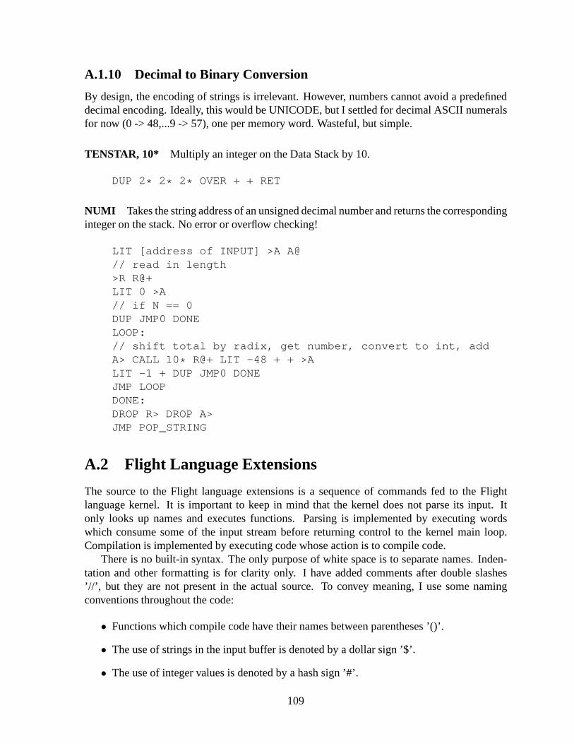
A.1.10 Decimal to Binary Conversion
By design, the encoding of strings is irrelevant. However, numbers cannot avoid a predefineddecimal encoding. Ideally, this would be UNICODE, but I settled for decimal ASCII numeralsfor now (0 -> 48,...9 -> 57), one per memory word. Wasteful, but simple.
TENSTAR, 10* Multiply an integer on the Data Stack by 10.
DUP 2* 2* 2* OVER + + RET
NUMI Takes the string address of an unsigned decimal number and returns the correspondinginteger on the stack. No error or overflow checking!
LIT [address of INPUT] >A A@// read in length>R R@+LIT 0 >A// if N == 0DUP JMP0 DONELOOP:// shift total by radix, get number, convert to int, addA> CALL 10* R@+ LIT -48 + + >ALIT -1 + DUP JMP0 DONEJMP LOOPDONE:DROP R> DROP A>JMP POP_STRING
A.2 Flight Language Extensions
The source to the Flight language extensions is a sequence ofcommands fed to the Flightlanguage kernel. It is important to keep in mind that the kernel does not parse its input. Itonly looks up names and executes functions. Parsing is implemented by executing wordswhich consume some of the input stream before returning control to the kernel main loop.Compilation is implemented by executing code whose action is to compile code.
There is no built-in syntax. The only purpose of white space is to separate names. Inden-tation and other formatting is for clarity only. I have addedcomments after double slashes’//’, but they are not present in the actual source. To conveymeaning, I use some namingconventions throughout the code:
• Functions which compile code have their names between parentheses ’()’.
• The use of strings in the input buffer is denoted by a dollar sign ’$’.
• The use of integer values is denoted by a hash sign ’#’.
109

• Moving data, input, and output is denoted by angle brackets ’<’ and ’>’.
The Flight language evolves very quickly at the beginning. The first few functions are usedthroughout the latter code and must be understood before proceeding further.
A.2.1 Making the Flight Language More Tractable
These utility functions make it easy to define functions, compile calls, read in numbers, and doname look-ups. They are used throughout the rest of the code.
// Creates a function named “:”// It scans in a string and creates a dictionary entry.SCAN : DEFNSCAN SCAN LOOK POP_STRING CMPCALLSCAN DEFN LOOK POP_STRING CMPCALL CMPRET
// Reads in a name and leaves the address of the// associated code on the stack.: lSCAN SCAN LOOK POP_STRING CMPCALLSCAN LOOK LOOK POP_STRING CMPCALLSCAN POP_STRING LOOK POP_STRING CMPCALL CMPRET
// Takes a string from the input buffer// and compiles a call to its associated code: $cl LOOK CMPCALLl POP_STRING CMPCALLl CMPCALL CMPCALL CMPRET
// Reads in a function name// and compiles a call to it: c SCAN SCAN $c SCAN $c $c CMPRET
// Reads an unsigned decimal number and leaves// its binary representation on the stack: n c SCAN c NUMI CMPRET
// Creates a new dictionary entry for// an existing function: alias c l c SCAN c DEFN_AS CMPRET
// Alias the built-in function names// to get away from C-style identifiers.alias CMPJMP (JMP)
110
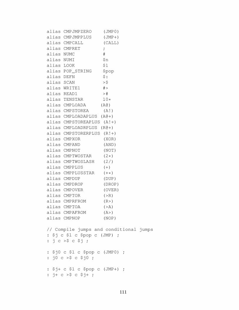
alias CMPJMPZERO (JMP0)alias CMPJMPPLUS (JMP+)alias CMPCALL (CALL)alias CMPRET ;alias NUMC #alias NUMI $nalias LOOK $lalias POP_STRING $popalias DEFN $:alias SCAN >$alias WRITE1 #>alias READ1 >#alias TENSTAR 10 *alias CMPLOADA (A@)alias CMPSTOREA (A!)alias CMPLOADAPLUS (A@+)alias CMPSTOREAPLUS (A!+)alias CMPLOADRPLUS (R@+)alias CMPSTORERPLUS (R!+)alias CMPXOR (XOR)alias CMPAND (AND)alias CMPNOT (NOT)alias CMPTWOSTAR (2* )alias CMPTWOSLASH (2/)alias CMPPLUS (+)alias CMPPLUSSTAR (+ * )alias CMPDUP (DUP)alias CMPDROP (DROP)alias CMPOVER (OVER)alias CMPTOR (>R)alias CMPRFROM (R>)alias CMPTOA (>A)alias CMPAFROM (A>)alias CMPNOP (NOP)
// Compile jumps and conditional jumps: $j c $l c $pop c (JMP) ;: j c >$ c $j ;
: $j0 c $l c $pop c (JMP0) ;: j0 c >$ c $j0 ;
: $j+ c $l c $pop c (JMP+) ;: j+ c >$ c $j+ ;
111

A.2.2 Interactively Usable Opcodes
These functions create interpreted versions of some opcodes to interactively manipulate mem-ory and the Data Stack. Opcodes which manipulate the A register and the Return Stack cannotbe interpreted since the interpretation process alters their contents.
: @ (>A) (A@) ;: ! (>A) (A!) ;: XOR (XOR) ;: AND (AND) ;: NOT (NOT) ;: OR (OVER) (NOT) (AND) (XOR) ;: 2 * (2 * ) ;: 2/ (2/) ;: + (+) ;: + * (+ * ) ;: DUP (DUP) ;: DROP (DROP) ;: OVER (OVER) ;: NOP (NOP) ;
A.2.3 Basic Compiling Functions
These are some compiling functions for common operations, mostly arithmetic.
// Compiles addition with a fetched constant: #+ c # c (+) ;// Compiles a decimal number literal fetch: n# c n c # ;// Compiles a function address literal fetch: l# c l c # ;
// Compile loads and stores and bitwise OR: (@) c (>A) c (A@) ;: (!) c (>A) c (A!) ;: (OR) c (OVER) c (NOT) c (AND) c (XOR) ;
// Negate, or compile its code: negate (NOT) n# 1 (+) ;: (negate) c (NOT) n# 1 c #+ ;
// Read in and negate a decimal: -n c n (negate) ;// Same, from the input buffer: -$n c $n (negate) ;
112

// Same, and compile as literal: -n# c -n c # ;
// Compiles code to read in a decimal// and compile it as a constant addition// Negate beforehand to make a subtraction: (N-) c -n c #+ ;: (N+) c n c #+ ;
// Synthesize subtraction: - (negate) (+) ;: (-) c (negate) c (+) ;
A.2.4 Terminal Control Characters
These output the basic terminal control characters (as counted strings of length 1).
: \a n# 7 n# 1 c #> j #>: \b n# 8 n# 1 c #> j #>: \t n# 9 n# 1 c #> j #>: \n n# 10 n# 1 c #> j #>: \v n# 11 n# 1 c #> j #>: \f n# 12 n# 1 c #> j #>: \r n# 13 n# 1 c #> j #>: \s n# 32 n# 1 c #> j #>
A.2.5 Conditionals and Comparisons
These functions implement the usual if/then construct. Thetwo conditions are “if non-zero”and “if negative”. Some usage examples follow.
// Compile a JMP0 to 0, and leave the address// of the jump address on the stack: ifn# 0 c (JMP0)l# HERE_NEXT (@)(N-) 1 ;
: if-n# 0 c (JMP+)l# HERE_NEXT (@)(N-) 1 ;
113

// Backpatch the jump to target// the next memory word: else(>R) c NEW_WORD (R>)(>A) (A!) ;
: max(OVER) (OVER) (-)if-
(>R) (DROP) (R>) ;else
(DROP) ;
: min(OVER) (OVER) (-)if-
(DROP) ;else
(>R) (DROP) (R>) ;
: abs(DUP) if- (negate) ; else ;
: <=(-) (DUP)if-
(DROP) -n# 1 ;else
ifn# 0 ;
else-n# 1 ;
: >=(-) (DUP)if-
(DROP) -n# 0 ;else
ifn# 0 ;
else-n# 1 ;
114

A.2.6 Code Memory Allocation
This function allocates a zeroed-out span of memory in the code area, usually for static storageof data.
: allot(DUP)if
c ALIGN(N-) 1j allot
else(DROP) ;
A.2.7 String Copying and Printing
These functions print strings and copy them between the input buffer and the code area.
// Copies a string between a source// and a destination address: $copy(>R) (>A)(A@) (A>) (+) (N+) 1: $copy-loop (A>) (OVER) (XOR)if (A@+) (R!+) j $copy-loopelse (DROP)(R>) (DUP) (>A) (A!) ;
// Copy a string from the input buffer// to the code area: $>cl# INPUT (@)l# HERE (@)(OVER) (@) (N+) 1 c allotc $copyc ALIGNj POP_STRING
// Copy a string from the code area// to input buffer: c>$(DUP) (@) c PUSH_STRINGl# INPUT (@)c $copy ;
115

// Output a string, given its address: cs>(DUP) (@) (+) (N+) 1(A>) (>R): cs>-loop (R>) (OVER) (OVER) (XOR)if (>R) (R@+) c #> j cs>-loopelse (DROP) (DROP) ;
// Output a string from the input buffer: $>l# INPUT (@)c cs>j POP_STRING
// Print a string, given its name// copy first to input buffer: $print c l c c>$ j $>// Same, without copying: csprint c l j cs>
A.2.8 De-Allocating Functions
Executing ’forget foo’ will move back the HERE, HERE_NEXT, THERE, and INPUT pointersto points just before the name and the code of the function ’foo’, in effect erasing it from thelanguage. This will also forget all functions that had been defined after ’foo’.
: match?l# INPUT (@) c STRING_TAIL (XOR) ;
: end?l NAME_END @ # (XOR) ;
: erase(DUP) l# THERE (!)(DUP) (N+) 1 l# INPUT (!)(@) (DUP)(N-) 1 l# HERE (!)l# HERE_NEXT (!)j ALIGN
116

: forgetc >$l# THERE (@) (N+) 1 (DUP): forget-loopl# INPUT (@)c COMPARE_STRINGSc match?if (DROP) c STRING_TAIL (N+) 1 (DUP) c end?
if(DUP) j forget-loop
else(DROP) c POP_STRING ;
elsec erase (DROP) ;
A.2.9 Unsigned Multiplication and Division
These functions synthesize unsigned integer multiplication and division. The multiplicationfunction takes two 15-bit integers and returns the 30-bit product. The division function has asimple error reporting mechanism if a division by zero is attempted. It will stop and send theremaining input to the output so the location of the fault is made visible.
: 15x15(>R)(2 * ) (2 * ) (2 * ) (2 * )(2 * ) (2 * ) (2 * ) (2 * )(2 * ) (2 * ) (2 * ) (2 * )(2 * ) (2 * ) (2 * )(R>)(+ * ) (2/) (+ * ) (2/) (+ * ) (2/) (+ * ) (2/)(+ * ) (2/) (+ * ) (2/) (+ * ) (2/) (+ * ) (2/)(+ * ) (2/) (+ * ) (2/) (+ * ) (2/) (+ * ) (2/)(+ * ) (2/) (+ * ) (2/) (+ * ) (2/) (+ * )(>R) (DROP) (R>) ;
: divby0msg >$ DIV_BY_0_ERROR $>c: divby0 l# divby0msg c cs> ;: errcontext c \s c >$ c $> j errcontext: divby0check(DUP) if ; else (DROP) (DROP) c divby0 j errcontext
117

: U/c divby0checkn# 0 (>A): U/-loop(OVER) (>R) (DUP) (R>) c <=if
(DUP) (>R) (-) (R>)(A>) (N+) 1 (>A)j U/-loop
else(DROP) (A>) ;
A.2.10 Binary to Decimal Conversion
: minus?if- n# 1 ; else n# 0 ;
: numstrlenc abs (DUP) (N-) 10if- (DROP) n# 1 ; else (DUP) (N-) 100if- (DROP) n# 2 ; else (DUP) (N-) 1000if- (DROP) n# 3 ; else (DUP) (N-) 10000if- (DROP) n# 4 ; else (DUP) (N-) 100000if- (DROP) n# 5 ; else (DUP) (N-) 1000000if- (DROP) n# 6 ; else (DUP) (N-) 10000000if- (DROP) n# 7 ; else (DUP) (N-) 100000000if- (DROP) n# 8 ; else (DUP) (N-) 1000000000if- (DROP) n# 9 ; else (DROP) n# 10 ;
// Converts a signed integer to a string// in the input buffer: #>$(DUP) c numstrlen (OVER) c minus? (+) c PUSH_STRING(DUP) if- n# 45 l# INPUT (@) (N+) 1 (!) c abs else(>R) l# INPUT (@) c STRING_TAIL (N-) 1 (R>): #>$-loopn# 10 c U/ (>R) n# 48 (+) (OVER) (!) (N-) 1 (R>)(DUP) if j #>$-loop else (DROP) (DROP) ;
// Convert and print a decimal number: #$> c #>$ c $> ;
118
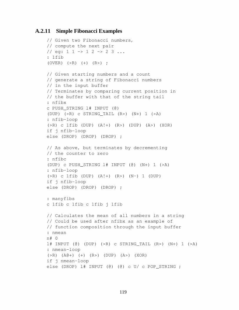
A.2.11 Simple Fibonacci Examples
// Given two Fibonacci numbers,// compute the next pair// eg: 1 1 -> 1 2 -> 2 3 ...: 1fib(OVER) (>R) (+) (R>) ;
// Given starting numbers and a count// generate a string of Fibonacci numbers// in the input buffer// Terminates by comparing current position in// the buffer with that of the string tail: nfibxc PUSH_STRING l# INPUT (@)(DUP) (>R) c STRING_TAIL (R>) (N+) 1 (>A): nfib-loop(>R) c 1fib (DUP) (A!+) (R>) (DUP) (A>) (XOR)if j nfib-loopelse (DROP) (DROP) (DROP) ;
// As above, but terminates by decrementing// the counter to zero: nfibc(DUP) c PUSH_STRING l# INPUT (@) (N+) 1 (>A): nfib-loop(>R) c 1fib (DUP) (A!+) (R>) (N-) 1 (DUP)if j nfib-loopelse (DROP) (DROP) (DROP) ;
: manyfibsc 1fib c 1fib c 1fib j 1fib
// Calculates the mean of all numbers in a string// Could be used after nfibx as an example of// function composition through the input buffer: nmeann# 0l# INPUT (@) (DUP) (>R) c STRING_TAIL (R>) (N+) 1 (>A): nmean-loop(>R) (A@+) (+) (R>) (DUP) (A>) (XOR)if j nmean-loopelse (DROP) l# INPUT (@) (@) c U/ c POP_STRING ;
119

A.2.12 Static Variables
This code creates the ability to store data in the code area atthe time a function in created.It is equivalent to C language static variables. This is usedto implement named variables asfunctions which return the address of the associated storage.
// Allocates one memory word and compiles code// to place its address on the Data Stack: createn# 0 c # l# HERE_NEXT (@) (N-) 1 (>R)n# 0 c (JMP) l# HERE (@) (N-) 1l# HERE (@) (R>) (!) ;
// This ends the data allocation and begins// the code that will use the address of the// allocated area.// Exact same code as else, so just alias it insteadalias else does
// Allocate a number of memory words, then// compile code to return its address: var c create (>R) (N-) 1 c allot (R>) c does ;
// Create a global variable named ’first’// with a size of one memory location: first n 1 var ;
// Store integer ’4’ in first// then load and print itn 4 first !first @ #$> \t
// Compile code as data// then call to it: passn# 1 c #$> c \tcreate
n# 2 c #$> c \n ;does
n# 3 c #$> c \tc EXECUTE ;
// Output: 1 3 2pass
120

A.2.13 Accumulator Generator
This is a simple example of generating code with an initial argument that becomes static data.
// Compile an integer into the code area: #>c l# HERE (@) (!) ;
// Compiles code that returns an accumulator// function using a provided integer// Returns the function’s address: accgenc NEW_WORD (>R)c create (>R) c #>c (R>) c doesc (@) c (+) c (DUP) c (A!) c ;(R>) ;
// Read in a name and associate it// with an address on the stack.: name-as c >$ c DEFN_AS ;
// Create two accumulators and test them.// Output: 8 7 10 9 17 16 117 116n 3 accgen name-as foon 2 accgen name-as barn 5 foo #$> \tn 5 bar #$> \tn 2 foo #$> \tn 2 bar #$> \tn 7 foo #$> \tn 7 bar #$> \tn 100 foo #$> \tn 100 bar #$> \t \n
A.2.14 Fibonacci Generator
Slightly more elaborate examples of code generation with static data.
// Generate a Fibonacci function that stores// its initial arguments in memory: fibgen1c :c create (>R) c #>c (R>) c doesc create (>R) c #>c (R>) c doesc (OVER) c (@) c (OVER) c (@) c (+) c (>R)c (OVER) c (@) c (OVER) c (!) c (DROP)c (>A) c (R>) c (DUP) c (A!) c ; ;
121

// Factored out Fibonacci code: memfib(OVER) (@) (OVER) (@) (+) (>R)(OVER) (@) (OVER) (!) (DROP)(>A) (R>) (DUP) (A!) ;
// Takes 2 numbers in the Fibonacci sequence// and returns a function that outputs the// next number in the sequence when called.// The two current sequence numbers are stored// within the function body.: fibgen2c :c create (>R) c #>c (R>) c doesc create (>R) c #>c (R>) c doesl# memfib c (CALL) c ; ;
n 0 n 1 fibgen2 fibonacci
// Output: 1 2 3 5 8 13 21 34fibonacci #$> \tfibonacci #$> \tfibonacci #$> \tfibonacci #$> \tfibonacci #$> \tfibonacci #$> \tfibonacci #$> \tfibonacci #$> \t \n
A.2.15 Caesar Cipher Generator
An initial example of a function being passed as a parameter.
// Add a given number to a memory location: caesar(>R) (>A) (R>) (A@) (+) (A!) ;
// Make one argument of caesar (the number)// a built-in parameter: caesargenc :c create (>R) c #>c (R>) c doesc (@) l# caesar c (CALL) c ; ;
122

n 3 caesargen encode-n 3 caesargen decode
// Takes the address of a string// and the name of a function.// Maps the function to each// element of the string.: map1(DUP) (>R) c STRING_TAIL (R>)(N+) 1c l (>R): map1-loop(DUP) (R>) (DUP) (>R) c EXECUTE (N+) 1(OVER) (OVER) (XOR)if j map1-loopelse (DROP) (DROP) (R>) (DROP) ;
// Input: ABCD// Output: ABCD DEFG ABCD>$ ABCD// Print the stringl INPUT @ DUP cs> \tDUP map1 encode// Print the ciphered versionDUP cs> \t// Print the deciphered versionDUP map1 decode$> \t \n
// Since the argument is a constant// it can be compiled as a literal fetch instead: caesargenc :c #l# caesar c (JMP) ;
123

A.2.16 Higher-Order Function (Map)
This is an example of a mapped function generator.
// Takes an integer and the function name of// a function that alters memory.// Compiles code which applies the given// function to each location in a string// at the interval provided by the integer: mapgenc (DUP) c (>R) l# STRING_TAIL c (CALL) c (R>)n 1 # c # c (+)c NEW_WORDc (DUP) c l c (CALL) (>R) c # (R>) c (+)c (OVER) c (OVER) c (XOR)c if (>R) c (JMP) (R>)c else c (DROP) c (DROP) c ; ;
n 5 caesargen encode1-n 5 caesargen decode1
// Apply encode1 to every other character in a string: cipher n 2 mapgen encode1// Apply decode1 to each character in a string: decipher n 1 mapgen decode1
// Input: lmnopq// Output:lmnopq qmsouq lhnjpl>$ lmnopql INPUT @ DUP cs> \tDUP cipherDUP cs> \tDUP decipher$> \t \n
// Given a memory address, print the// decimal expression of its contents: print# (@) c #$> c \t ;// Apply print# to each location in a string: print$# n 1 mapgen print#
// Generate and print// the first 8 Fibonacci numbers// Output: 1 1 2 3 5 8 13 21n 1 n 0 n 8 nfibxl INPUT @ print$# POP_STRING
124
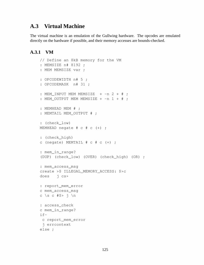
A.3 Virtual Machine
The virtual machine is an emulation of the Gullwing hardware. The opcodes are emulateddirectly on the hardware if possible, and their memory accesses are bounds-checked.
A.3.1 VM
// Define an 8kB memory for the VM: MEMSIZE n# 8192 ;: MEM MEMSIZE var ;
: OPCODEWIDTH n# 5 ;: OPCODEMASK n# 31 ;
: MEM_INPUT MEM MEMSIZE + -n 2 + # ;: MEM_OUTPUT MEM MEMSIZE + -n 1 + # ;
: MEMHEAD MEM # ;: MEMTAIL MEM_OUTPUT # ;
: (check_low)MEMHEAD negate # c # c (+) ;
: (check_high)c (negate) MEMTAIL # c # c (+) ;
: mem_in_range?(DUP) (check_low) (OVER) (check_high) (OR) ;
: mem_access_msgcreate >$ ILLEGAL_MEMORY_ACCESS: $>cdoes j cs>
: report_mem_errorc mem_access_msgc \s c #$> j \n
: access_checkc mem_in_range?if-
c report_mem_errorj errcontext
else ;
125

: PCFETCHopcode n# 0 ;: CALLopcode n# 1 ;: RETopcode n# 2 ;: JMPopcode n# 3 ;: JMPZEROopcode n# 4 ;: JMPPLUSopcode n# 5 ;: LOADAopcode n# 6 ;: STOREAopcode n# 7 ;: LOADAPLUSopcode n# 8 ;: STOREAPLUSopcode n# 9 ;: LOADRPLUSopcode n# 10 ;: STORERPLUSopcode n# 11 ;: LITopcode n# 12 ;: UND0opcode n# 13 ;: UND1opcode n# 14 ;: UND2opcode n# 15 ;: XORopcode n# 16 ;: ANDopcode n# 17 ;: NOTopcode n# 18 ;: TWOSTARopcode n# 19 ;: TWOSLASHopcode n# 20 ;: PLUSopcode n# 21 ;: PLUSSTARopcode n# 22 ;: DUPopcode n# 23 ;: DROPopcode n# 24 ;: OVERopcode n# 25 ;: TORopcode n# 26 ;: RFROMopcode n# 27 ;: TOAopcode n# 28 ;: AFROMopcode n# 29 ;: NOPopcode n# 30 ;: UND3opcode n# 31 ;
// Emulated A, PC and ISR: AREG n 1 var ;: PCREG n 1 var ;: ISRREG n 1 var ;
: do_pcfetchPCREG # (@)c access_check (DUP)(N+) 1 (A!)(@) ISRREG # (!) ;
126
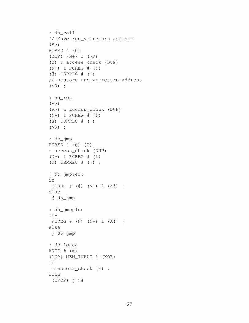
: do_call// Move run_vm return address(R>)PCREG # (@)(DUP) (N+) 1 (>R)(@) c access_check (DUP)(N+) 1 PCREG # (!)(@) ISRREG # (!)// Restore run_vm return address(>R) ;
: do_ret(R>)(R>) c access_check (DUP)(N+) 1 PCREG # (!)(@) ISRREG # (!)(>R) ;
: do_jmpPCREG # (@) (@)c access_check (DUP)(N+) 1 PCREG # (!)(@) ISRREG # (!) ;
: do_jmpzeroif
PCREG # (@) (N+) 1 (A!) ;else
j do_jmp
: do_jmpplusif-
PCREG # (@) (N+) 1 (A!) ;else
j do_jmp
: do_loadaAREG # (@)(DUP) MEM_INPUT # (XOR)if
c access_check (@) ;else
(DROP) j >#
127

: do_storeaAREG # (@)(DUP) MEM_OUTPUT # (XOR)if
c access_check (!) ;else
(DROP) j #>
: do_loadaplusAREG # (@)(DUP) MEM_INPUT # (XOR)if
c access_check(>A) (A@+) (A>)AREG # (!) ;
else(N+) 1 AREG # (!) j >#
: do_storeaplusAREG # (@)(DUP) MEM_OUTPUT # (XOR)if
c access_check(>A) (A!+) (A>)AREG # (!) ;
else(N+) 1 AREG # (!) j #>
: do_loadrplus(R>) (>A)(R>)(DUP) MEM_INPUT # (XOR)if
c access_check(>R) (R@+)(A>) (>R) ;
else(N+) 1 (>R)(A>) (>R)j >#
128
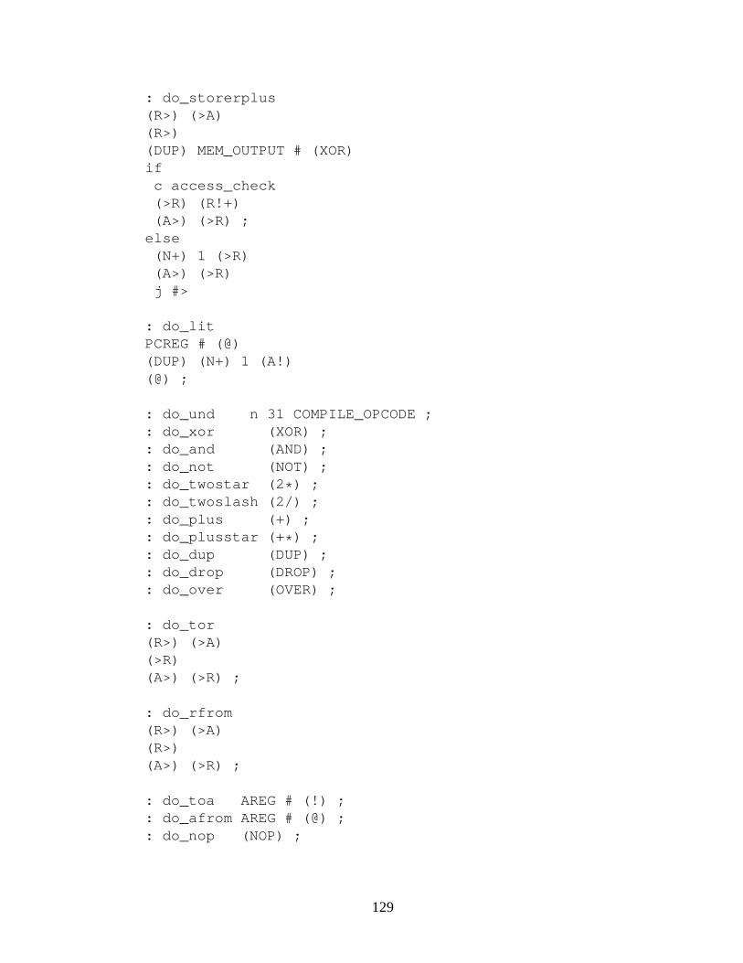
: do_storerplus(R>) (>A)(R>)(DUP) MEM_OUTPUT # (XOR)if
c access_check(>R) (R!+)(A>) (>R) ;
else(N+) 1 (>R)(A>) (>R)j #>
: do_litPCREG # (@)(DUP) (N+) 1 (A!)(@) ;
: do_und n 31 COMPILE_OPCODE ;: do_xor (XOR) ;: do_and (AND) ;: do_not (NOT) ;: do_twostar (2 * ) ;: do_twoslash (2/) ;: do_plus (+) ;: do_plusstar (+ * ) ;: do_dup (DUP) ;: do_drop (DROP) ;: do_over (OVER) ;
: do_tor(R>) (>A)(>R)(A>) (>R) ;
: do_rfrom(R>) (>A)(R>)(A>) (>R) ;
: do_toa AREG # (!) ;: do_afrom AREG # (@) ;: do_nop (NOP) ;
129

: ,c #>c c ALIGN ;
: &>c l c , ;
// Indexed by the opcode: instruction_call_tablecreate&> do_pcfetch&> do_call&> do_ret&> do_jmp&> do_jmpzero&> do_jmpplus&> do_loada&> do_storea&> do_loadaplus&> do_storeaplus&> do_loadrplus&> do_storerplus&> do_lit&> do_und&> do_und&> do_und&> do_xor&> do_and&> do_not&> do_twostar&> do_twoslash&> do_plus&> do_plusstar&> do_dup&> do_drop&> do_over&> do_tor&> do_rfrom&> do_toa&> do_afrom&> do_nop&> do_unddoes ;
130

: (shift_isr)c (2/) c (2/) c (2/) c (2/) c (2/) ;
: (extract_instruction)OPCODEMASK # c # c (AND) ;
: do_next_instructionISRREG # (@)(DUP) (shift_isr) (A!)(extract_instruction)instruction_call_table # (+) (@)(>R) ;
// All input now gets processed by the software// inside the VM instead of the original Flight language kern el: run_vmMEM # PCREG # (!)n 0 # ISRREG # (!)n 123456 # AREG # (!): vm_loopc do_next_instructionj vm_loop
// Output short message to show// that compilation reached this point>$ VM4-1 $> \n
A.3.2 Metacompiler
The metacompiler saves and restores the internal state of the language kernel. This allowsredirecting the operation of the kernel to a different memory area. In this case, it is used todirect compilation and execution of code to the previously defined Virtual Machine memoryarea.
// Virtual Machine state: vm_here n 1 var ;: vm_here_next n 1 var ;: vm_there n 1 var ;: vm_slot n 1 var ;: vm_input n 1 var ;: vm_name_end n 1 var ;
// Native Machine state: nm_here n 1 var ;: nm_here_next n 1 var ;
131

: nm_there n 1 var ;: nm_slot n 1 var ;: nm_input n 1 var ;: nm_name_end n 1 var ;
: save_nm_here l# HERE (@) nm_here # (!) ;: save_nm_here_next l# HERE_NEXT (@) nm_here_next # (!) ;: save_nm_slot l# SLOT (@) nm_slot # (!) ;: save_nm_input l# INPUT (@) nm_input # (!) ;: save_nm_there l# THERE (@) nm_there # (!) ;: save_nm_name_end l# NAME_END (@) nm_name_end # (!) ;
: save_vm_here l# HERE (@) vm_here # (!) ;: save_vm_here_next l# HERE_NEXT (@) vm_here_next # (!) ;: save_vm_slot l# SLOT (@) vm_slot # (!) ;: save_vm_input l# INPUT (@) vm_input # (!) ;: save_vm_there l# THERE (@) vm_there # (!) ;: save_vm_name_end l# NAME_END (@) vm_name_end # (!) ;
: restore_nm_here nm_here # (@) l# HERE (!) ;: restore_nm_here_nextnm_here_next # (@) l# HERE_NEXT (!) ;: restore_nm_slot nm_slot # (@) l# SLOT (!) ;: restore_nm_input nm_input # (@) l# INPUT (!) ;: restore_nm_there nm_there # (@) l# THERE (!) ;: restore_nm_name_end nm_name_end # (@) l# NAME_END (!) ;
: restore_vm_here vm_here # (@) l# HERE (!) ;: restore_vm_here_nextvm_here_next # (@) l# HERE_NEXT (!) ;: restore_vm_slot vm_slot # (@) l# SLOT (!) ;: restore_vm_input vm_input # (@) l# INPUT (!) ;: restore_vm_there vm_there # (@) l# THERE (!) ;: restore_vm_name_end vm_name_end # (@) l# NAME_END (!) ;
: init_vm_here MEM # vm_here # (!) n# 0 (A@) (!) ;: init_vm_here_nextMEM n 1 + # vm_here_next # (!) n# 0 (A@) (!) ;: init_vm_slot n# 0 vm_slot # (!) ;: init_vm_there MEM_INPUT n 1 - # vm_there # (!) ;: init_vm_input MEM_INPUT # vm_input # (!) ;: init_vm_name_end MEM_INPUT # vm_name_end # (!) ;
132

// Flight Language Kernel main loop while in VM.// (Compare with NXEC)// Lookup names in VM dictionary, and if not found,// repeat in native machine dictionary.: vm_nxecc SCANc LOOK(DUP) l# NAME_END (@) (XOR)// If found in VM memoryif
c POP_STRINGc EXECUTEj vm_nxec
else// Else find in native machine memory// but execute with kernel pointed at VM memory
(DROP)c save_vm_therec save_vm_name_endc restore_nm_therec restore_nm_name_endc LOOKc save_nm_therec save_nm_name_endc restore_vm_therec restore_vm_name_endc POP_STRINGc EXECUTEj vm_nxec
: init_name_dictcreate >$ zeroword $>cdoes c c>$ n# 0 c DEFN_AS ;
// Drop current caller address: (unwind) c (R>) c (DROP) ;
// Begin execution inside VM: VM(c init_vm_herec init_vm_here_nextc init_vm_slotc init_vm_therec init_vm_inputc init_vm_name_end
133

c save_nm_herec save_nm_here_nextc save_nm_slotc save_nm_therec save_nm_inputc save_nm_name_endc restore_vm_herec restore_vm_here_nextc restore_vm_slotc restore_vm_therec restore_vm_inputc restore_vm_name_endc init_name_dict// Change the main loop(unwind)j vm_nxec
// End execution inside VM: )VMc save_vm_herec save_vm_here_nextc save_vm_slotc save_vm_therec save_vm_inputc save_vm_name_endc restore_nm_herec restore_nm_here_nextc restore_nm_slotc restore_nm_therec restore_nm_inputc restore_nm_name_end// Change the main loop(unwind)j NXEC
// Print this to signal we got this far>$ METACOMP1 $> \n
134

A.3.3 Self-hosted Kernel
This is a reimplementation of the Flight language kernel, written in the language it defines,using all the extensions previously compiled. It compiles to the same original machine codein which the kernel was originally implemented (Section A.1), but it is compiled in the VirtualMachine memory area instead.
VM(
n 0 (JMP) MEM n 1 + >$ START_WORD DEFN_AS
: HERE: HERE_NEXT: THERE: SLOT: INPUT: NAME_END
: MINUS (NOT) n# 1 (+) (+) ;: OR (OVER) (NOT) (AND) (XOR) ;
: READ1 MEM_INPUT # (@) ;: WRITE1 MEM_OUTPUT # (!) ;: STRING_TAIL (>A) (A@+) (A>) (+) ;
: PUSH_STRING(DUP) n# 1 (+) (NOT)l# INPUT (@) (+) (DUP) (A!)(!)l# INPUT (@)c STRING_TAIL(DUP) (!) ;
: POP_STRINGl# INPUT (@)c STRING_TAILn# 1 (+)l# INPUT (!) ;
: COMPARE_STRINGS(>A) (>R): CS_LOOP(R@+) (A@+) (XOR)j0 CS_LOOP-n# 1 (R>) (+)-n# 1 (A>) (+) ;
135

: SCAN_STRINGl# INPUT (@) (>R) (R@+): SS_LOOPc READ1 (R!+)-n# 1 (+) (DUP)if
j SS_LOOPelse
(DROP) (R>) (DUP) (!) ;
: SCANc READ1c PUSH_STRINGj SCAN_STRING
: FIRST_SLOTl# SLOT (>A)n# 31 (A!) ;
: LAST_SLOTl# SLOT (>A)n# 1040187392 (A!) ;
: NULL_SLOTl# SLOT (>A)n# 0 (A!) ;
: ALIGNl# HERE_NEXT (@)(DUP) (>R) n# 0 (R!+)(R>) (A!)l# HERE (!)j NULL_SLOT
: NEXT_SLOTl# SLOT (@)n# 0 (OVER) (XOR)if
n# 1040187392 (OVER) (XOR)if
(2 * ) (2 * ) (2 * ) (2 * ) (2 * ) (A!) ;else
(DROP) c ALIGN j FIRST_SLOTelse
(DROP) j FIRST_SLOT
136
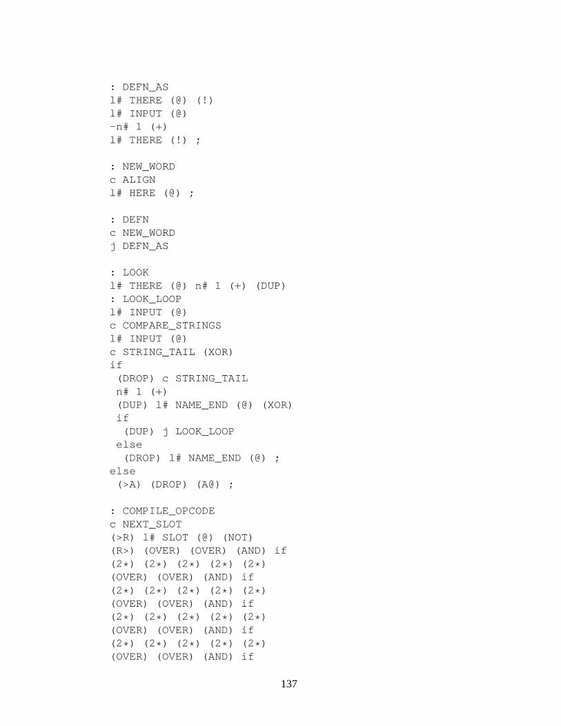
: DEFN_ASl# THERE (@) (!)l# INPUT (@)-n# 1 (+)l# THERE (!) ;
: NEW_WORDc ALIGNl# HERE (@) ;
: DEFNc NEW_WORDj DEFN_AS
: LOOKl# THERE (@) n# 1 (+) (DUP): LOOK_LOOPl# INPUT (@)c COMPARE_STRINGSl# INPUT (@)c STRING_TAIL (XOR)if
(DROP) c STRING_TAILn# 1 (+)(DUP) l# NAME_END (@) (XOR)if
(DUP) j LOOK_LOOPelse
(DROP) l# NAME_END (@) ;else
(>A) (DROP) (A@) ;
: COMPILE_OPCODEc NEXT_SLOT(>R) l# SLOT (@) (NOT)(R>) (OVER) (OVER) (AND) if(2 * ) (2 * ) (2 * ) (2 * ) (2 * )(OVER) (OVER) (AND) if(2 * ) (2 * ) (2 * ) (2 * ) (2 * )(OVER) (OVER) (AND) if(2 * ) (2 * ) (2 * ) (2 * ) (2 * )(OVER) (OVER) (AND) if(2 * ) (2 * ) (2 * ) (2 * ) (2 * )(OVER) (OVER) (AND) if
137

(2 * ) (2 * ) (2 * ) (2 * ) (2 * )else else else else elsel# HERE (@)(@) (+) (A!) (DROP) ;
: COMPILE_LITERALl# HERE_NEXT (@)(>A) (A!+)(A>) l# HERE_NEXT (!) ;
: CMPCALLCALLopcode # c COMPILE_OPCODE c COMPILE_LITERAL j ALIGN: CMPJMPJMPopcode # c COMPILE_OPCODE c COMPILE_LITERAL j ALIGN: CMPJMPZEROJMPZEROopcode # c COMPILE_OPCODE j COMPILE_LITERAL: CMPJMPPLUSJMPPLUSopcode # c COMPILE_OPCODE j COMPILE_LITERAL: NUMCLITopcode # c COMPILE_OPCODE j COMPILE_LITERAL: CMPPCFETCH PCFETCHopcode # j COMPILE_OPCODE: CMPRET RETopcode # j COMPILE_OPCODE: CMPLOADAPLUS LOADAPLUSopcode # j COMPILE_OPCODE: CMPLOADRPLUS LOADRPLUSopcode # j COMPILE_OPCODE: CMPLOADA LOADAopcode # j COMPILE_OPCODE: CMPSTOREAPLUS STOREAPLUSopcode # j COMPILE_OPCODE: CMPSTORERPLUS STORERPLUSopcode # j COMPILE_OPCODE: CMPSTOREA STOREAopcode # j COMPILE_OPCODE: CMPNOT NOTopcode # j COMPILE_OPCODE: CMPAND ANDopcode # j COMPILE_OPCODE: CMPXOR XORopcode # j COMPILE_OPCODE: CMPPLUS PLUSopcode # j COMPILE_OPCODE: CMPTWOSTAR TWOSTARopcode # j COMPILE_OPCODE: CMPTWOSLASH TWOSLASHopcode # j COMPILE_OPCODE: CMPPLUSSTAR PLUSSTARopcode # j COMPILE_OPCODE: CMPAFROM AFROMopcode # j COMPILE_OPCODE: CMPTOA TOAopcode # j COMPILE_OPCODE: CMPDUP DUPopcode # j COMPILE_OPCODE: CMPDROP DROPopcode # j COMPILE_OPCODE: CMPOVER OVERopcode # j COMPILE_OPCODE: CMPTOR TORopcode # j COMPILE_OPCODE: CMPRFROM RFROMopcode # j COMPILE_OPCODE: CMPNOP NOPopcode # j COMPILE_OPCODE
: EXECUTE (>R) ;
138

: EXECc READ1c EXECUTEj EXEC
: NXECc SCANc LOOKc POP_STRINGc EXECUTEj NXEC
: TENSTAR(DUP) (2 * ) (2 * ) (2 * ) (OVER) (+) (+) ;
: NUMIl# INPUT (@)(>R) (R@+)n# 0 (>A)(DUP)if
: NUMI_LOOP(A>) c TENSTAR (R@+) -n# 48 (+) (+) (>A)-n# 1 (+) (DUP)if
j NUMI_LOOPelse
else(DROP) (R>) (DROP) (A>)j POP_STRING
l NXEC l START_WORD !
save_vm_here vm_here @ l HERE !save_vm_here_next vm_here_next @ l HERE_NEXT !save_vm_slot vm_slot @ l SLOT !save_vm_input vm_input @ l INPUT !save_vm_there vm_there @ l THERE !save_vm_name_end vm_name_end @ l NAME_END !
)VM
>$ FIF1 $> \n
139
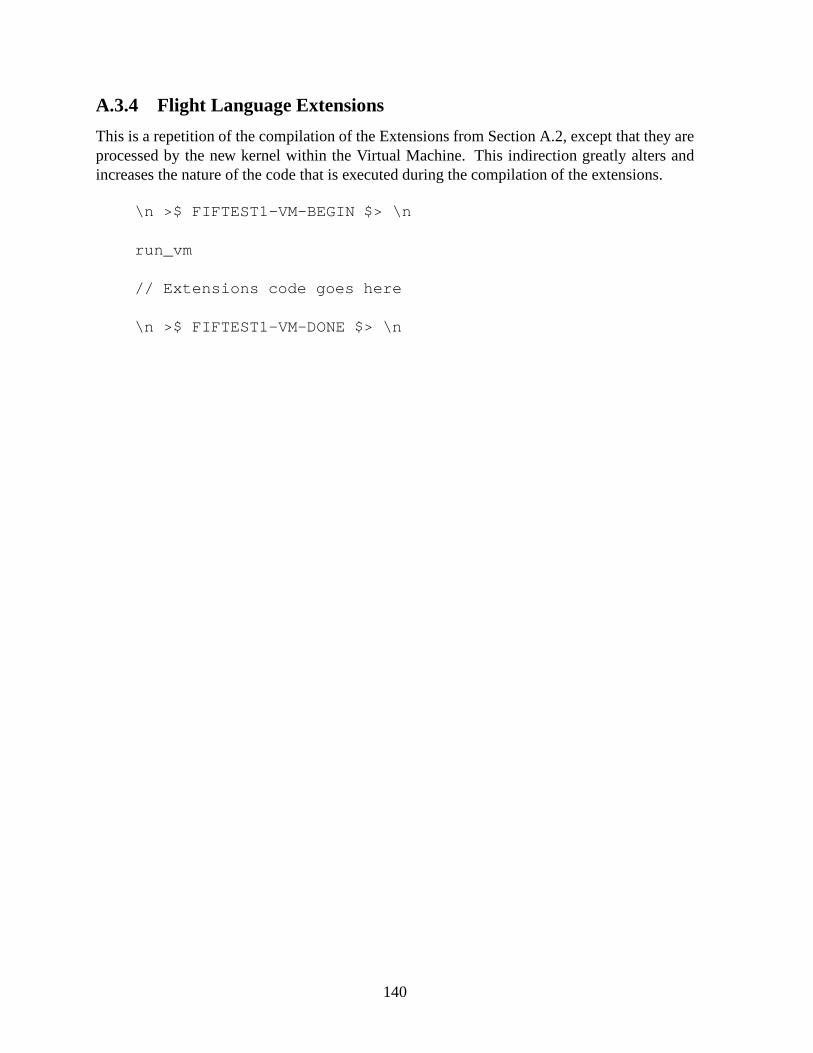
A.3.4 Flight Language Extensions
This is a repetition of the compilation of the Extensions from Section A.2, except that they areprocessed by the new kernel within the Virtual Machine. Thisindirection greatly alters andincreases the nature of the code that is executed during the compilation of the extensions.
\n >$ FIFTEST1-VM-BEGIN $> \n
run_vm
// Extensions code goes here
\n >$ FIFTEST1-VM-DONE $> \n
140

Appendix B
Static and Dynamic Gullwing CodeAnalyses
The following analyses are based on the software developed in Appendix A for the Gullwingprocessor. The analyses are imperfect since it cannot always be known if a memory wordcontains instructions or a literal. For example, this happens wherever the software containsdirectly accessed memory locations. These memory locations are neither executed nor accessedin-line like literal fetches. The analysis software considers these memory locations to containinstructions by default, despite actually being literals.Fortunately, such cases are infrequentand contribute very little noise to the data, showing up as rare, large literal values and UNDinstructions.
B.1 Static Analyses
The static analyses are done on the binary code resident in memory after each test was compiledand run. The symbol table associated with the executable code was removed prior to analysis.
B.1.1 Memory Usage
Table B.1 shows the total size of the code measured in (32-bit) memory words. This is dividedinto words which contain either instructions or literal values. The literals are further divided asaddresses and as actual literal values.
32-bit Words Bare Ratio Ext. Ratio VM Ratio
Total 286 1.000 1185 1.000 3029 1.000Instruction 123 0.430 593 0.500 1565 0.517
Literal 163 0.570 592 0.500 1464 0.483
Literal Types (words)Literal 79 0.485 215 0.363 593 0.405
Address 84 0.515 377 0.637 871 0.595
Table B.1: Compiled Flight Code Memory Usage
141

B.1.2 Range of Literals
Table B.2 shows the distribution of the required number of bits required to represent the abso-lute value of literals in immediate fetches. Most of these are small constants used in calcula-tions.
Bits Bare Ratio Ext. Ratio VM Ratio
4 56 0.709 168 0.781 340 0.5738 17 0.215 22 0.102 63 0.10612 1 0.013 13 0.060 73 0.12316 2 0.025 4 0.019 101 0.17020 0 0.000 2 0.009 5 0.00824 0 0.000 1 0.005 2 0.00328 0 0.000 1 0.005 2 0.00332 3 0.038 4 0.019 7 0.012
Table B.2: Range of Literals by Absolute Value
B.1.3 Range of Addresses
Table B.3 shows the distribution of the required number of bits required to represent the abso-lute value of addresses used for calls and jumps. As the code size increases, the number of bitsrequired to represent an address increases proportionally.
Bits Bare Ratio Ext. Ratio VM Ratio
4 3 0.036 22 0.058 34 0.0398 70 0.833 187 0.496 224 0.25712 7 0.083 164 0.435 516 0.59216 1 0.012 2 0.005 95 0.10920 0 0.000 0 0.000 0 0.00024 2 0.024 0 0.000 0 0.00028 0 0.000 2 0.005 2 0.00232 1 0.012 0 0.000 0 0.000
Table B.3: Range of Addresses by Absolute Value
142

B.1.4 Instructions per Instruction Word
Table B.4 shows the distribution of the number of instructions compiled into memory words.The PC@ (PC Fetch) instruction is not counted since it is usedto fill the empty instruction slots.A memory word which contains zero instructions is thus actually filled with PC@ instructions.
#/Word Bare Ratio Ext. Ratio VM Ratio
0 0 0.000 32 0.054 126 0.0811 28 0.228 242 0.408 595 0.3802 38 0.309 132 0.223 347 0.2223 3 0.024 44 0.074 140 0.0894 16 0.130 34 0.057 75 0.0485 7 0.057 18 0.030 44 0.0286 31 0.252 91 0.153 238 0.152
Table B.4: Instructions per Instruction Word
B.1.5 Instruction Density
Table B.5 shows the number of instructions per memory word. The averages are computedagainst both all memory words and against only those which contain instructions. The max-imum number of instructions per any memory word is a functionof the division between in-struction and literal words seen in Table B.1.
Instr. per Mem. Word Bare Ext. VM
Avg. per Any Word 1.392 1.190 1.207Max. per Any Word 2.580 3.003 3.100
Avg. per Instruction Word 3.236 2.380 2.337
Total # of Instr. 398 1410 3657Total Instr. Slots 738 3558 9390
Slot Usage 0.539 0.396 0.389
Table B.5: Instruction Density
143
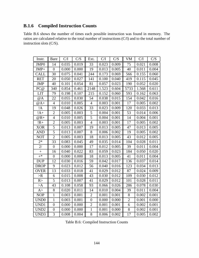
B.1.6 Compiled Instruction Counts
Table B.6 shows the number of times each possible instruction was found in memory. Theratios are calculated relative to the total number of instructions (C/I) and to the total number ofinstruction slots (C/S).
Instr. Bare C/I C/S Ext. C/I C/S VM C/I C/S
JMP0 14 0.035 0.019 33 0.023 0.009 75 0.021 0.008JMP+ 0 0.000 0.000 19 0.013 0.005 40 0.011 0.004CALL 30 0.075 0.041 244 0.173 0.069 566 0.155 0.060RET 20 0.050 0.027 141 0.100 0.040 419 0.115 0.045JMP 40 0.101 0.054 81 0.057 0.023 190 0.052 0.020PC@ 340 0.854 0.461 2148 1.523 0.604 5733 1.568 0.611LIT 79 0.198 0.107 215 0.152 0.060 593 0.162 0.063@A 22 0.055 0.030 54 0.038 0.015 154 0.042 0.016
@A+ 4 0.010 0.005 4 0.003 0.001 17 0.005 0.002!A 19 0.048 0.026 33 0.023 0.009 120 0.033 0.013
!A+ 2 0.005 0.003 5 0.004 0.001 53 0.014 0.006@R+ 4 0.010 0.005 5 0.004 0.001 14 0.004 0.001!R+ 2 0.005 0.003 4 0.003 0.001 17 0.005 0.002XOR 5 0.013 0.007 19 0.013 0.005 47 0.013 0.005AND 5 0.013 0.007 8 0.006 0.002 19 0.005 0.002NOT 2 0.005 0.003 18 0.013 0.005 43 0.012 0.0052* 33 0.083 0.045 49 0.035 0.014 104 0.028 0.0112/ 0 0.000 0.000 17 0.012 0.005 39 0.011 0.004+ 16 0.040 0.022 83 0.059 0.023 184 0.050 0.020+* 0 0.000 0.000 18 0.013 0.005 41 0.011 0.004
DUP 12 0.030 0.016 59 0.042 0.017 136 0.037 0.014DROP 9 0.023 0.012 56 0.040 0.016 123 0.034 0.013OVER 13 0.033 0.018 41 0.029 0.012 87 0.024 0.009
>R 6 0.015 0.008 43 0.030 0.012 109 0.030 0.012R> 5 0.013 0.007 41 0.029 0.012 101 0.028 0.011>A 43 0.108 0.058 93 0.066 0.026 286 0.078 0.030A> 8 0.020 0.011 14 0.010 0.004 39 0.011 0.004
NOP 1 0.003 0.001 2 0.001 0.001 8 0.002 0.001UND0 1 0.003 0.001 0 0.000 0.000 2 0.001 0.000UND1 0 0.000 0.000 2 0.001 0.001 6 0.002 0.001UND2 0 0.000 0.000 1 0.001 0.000 8 0.002 0.001UND3 3 0.008 0.004 8 0.006 0.002 17 0.005 0.002
Table B.6: Compiled Instruction Counts
144

B.2 Dynamic Analyses
The dynamic analyses are done on an execution trace log of each test in Appendix A. The’Bare’ case present in the static analyses is not included since the Flight language kernel isbuilt into the simulator and does virtually nothing withoutexternal input.
B.2.1 Overall Execution
Table B.7 lists the total number of executed instructions and the number of cycles they required.An average CPI (Cycles Per Instruction) of 1.3 is implied by these values.
Test Ext. VM
Instructions 5,018,751 204,325,372Cycles 6,574,996 265,567,537
Table B.7: Overall Execution
B.2.2 Executed Instruction Counts
Table B.8 lists the number of times each instruction was executed and its ratios relative to thetotal number of instructions (C/I) and cycles (C/C) executed. The conditional jumps are dividedinto taken and not taken instances since they have differentcycle counts (2 and 1, respectively).
A fold is a case where the fetching of the next group of instructions (a PC@) is executedconcurrently with the last instruction from the current group, thus occurring ’for free’. Theimplementation of this feature is detailed in Section 6.3.1. A PC@ (PC Fetch) instruction isexecuted after the last instruction when this folding cannot be done. The sum of the folds andPC@s is the total number of instruction fetches not originating from jumps, calls, or returns.
145
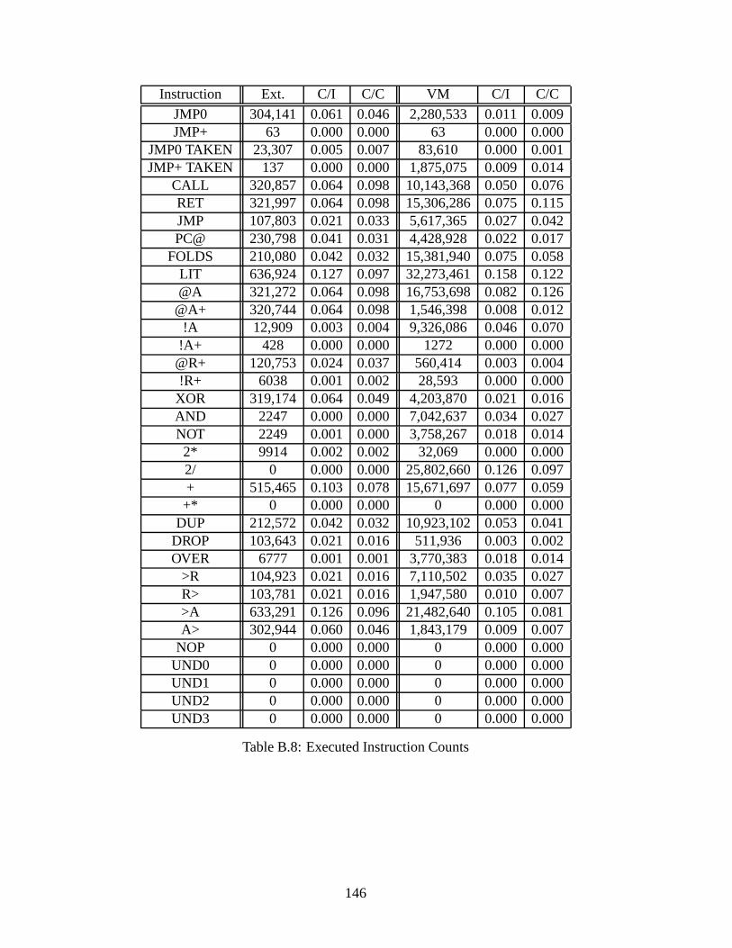
Instruction Ext. C/I C/C VM C/I C/C
JMP0 304,141 0.061 0.046 2,280,533 0.011 0.009JMP+ 63 0.000 0.000 63 0.000 0.000
JMP0 TAKEN 23,307 0.005 0.007 83,610 0.000 0.001JMP+ TAKEN 137 0.000 0.000 1,875,075 0.009 0.014
CALL 320,857 0.064 0.098 10,143,368 0.050 0.076RET 321,997 0.064 0.098 15,306,286 0.075 0.115JMP 107,803 0.021 0.033 5,617,365 0.027 0.042PC@ 230,798 0.041 0.031 4,428,928 0.022 0.017
FOLDS 210,080 0.042 0.032 15,381,940 0.075 0.058LIT 636,924 0.127 0.097 32,273,461 0.158 0.122@A 321,272 0.064 0.098 16,753,698 0.082 0.126
@A+ 320,744 0.064 0.098 1,546,398 0.008 0.012!A 12,909 0.003 0.004 9,326,086 0.046 0.070
!A+ 428 0.000 0.000 1272 0.000 0.000@R+ 120,753 0.024 0.037 560,414 0.003 0.004!R+ 6038 0.001 0.002 28,593 0.000 0.000XOR 319,174 0.064 0.049 4,203,870 0.021 0.016AND 2247 0.000 0.000 7,042,637 0.034 0.027NOT 2249 0.001 0.000 3,758,267 0.018 0.0142* 9914 0.002 0.002 32,069 0.000 0.0002/ 0 0.000 0.000 25,802,660 0.126 0.097+ 515,465 0.103 0.078 15,671,697 0.077 0.059+* 0 0.000 0.000 0 0.000 0.000
DUP 212,572 0.042 0.032 10,923,102 0.053 0.041DROP 103,643 0.021 0.016 511,936 0.003 0.002OVER 6777 0.001 0.001 3,770,383 0.018 0.014
>R 104,923 0.021 0.016 7,110,502 0.035 0.027R> 103,781 0.021 0.016 1,947,580 0.010 0.007>A 633,291 0.126 0.096 21,482,640 0.105 0.081A> 302,944 0.060 0.046 1,843,179 0.009 0.007
NOP 0 0.000 0.000 0 0.000 0.000UND0 0 0.000 0.000 0 0.000 0.000UND1 0 0.000 0.000 0 0.000 0.000UND2 0 0.000 0.000 0 0.000 0.000UND3 0 0.000 0.000 0 0.000 0.000
Table B.8: Executed Instruction Counts
146
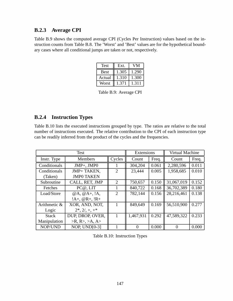
B.2.3 Average CPI
Table B.9 shows the computed average CPI (Cycles Per Instruction) values based on the in-struction counts from Table B.8. The ’Worst’ and ’Best’ values are for the hypothetical bound-ary cases where all conditional jumps are taken or not, respectively.
Test Ext. VM
Best 1.305 1.290Actual 1.310 1.300Worst 1.371 1.311
Table B.9: Average CPI
B.2.4 Instruction Types
Table B.10 lists the executed instructions grouped by type.The ratios are relative to the totalnumber of instructions executed. The relative contribution to the CPI of each instruction typecan be readily inferred from the product of the cycles and thefrequencies.
Test Extensions Virtual Machine
Instr. Type Members Cycles Count Freq. Count Freq.
Conditionals JMP+, JMP0 1 304,204 0.061 2,280,596 0.011Conditionals JMP+ TAKEN, 2 23,444 0.005 1,958,685 0.010
(Taken) JMP0 TAKENSubroutine CALL, RET, JMP 2 750,657 0.150 31,067,019 0.152
Fetches PC@, LIT 1 840,722 0.168 36,702,389 0.180Load/Store @A, @A+, !A, 2 782,144 0.156 28,216,461 0.138
!A+, @R+, !R+Arithmetic & XOR, AND, NOT, 1 849,649 0.169 56,510,900 0.277
Logic 2*, 2/, +, +*Stack DUP, DROP, OVER, 1 1,467,931 0.292 47,589,322 0.233
Manipulation >R, R>, >A, A>NOP/UND NOP, UND[0-3] 1 0 0.000 0 0.000
Table B.10: Instruction Types
147

B.2.5 Basic Block Length
Table B.11 lists the lengths, measured in instructions, of the basic blocks encountered duringexecution. Calls, returns, and jumps (taken or not) terminate a basic block. A block length ofzero signifies two consecutive calls or jumps.
The odd peak at length 17 is the main loop of the VM,do_next_instruction , whichwas deliberately inlined into a single basic block for performance reasons.
Instructions Ext. Ratio VM Ratio
0 24,613 0.023 17,143,651 0.4861 300,464 0.279 2,372,695 0.0672 394 0.000 661,029 0.0193 230,485 0.214 2,118,717 0.0604 208,813 0.194 940,229 0.0275 103,499 0.096 741,651 0.0216 3292 0.003 1,099,523 0.0317 100,262 0.093 719,878 0.0208 100,824 0.094 394,367 0.0119 3108 0.003 647,462 0.01810 - - 317,034 0.00911 77 0.000 322,764 0.00912 43 0.000 132,018 0.00413 61 0.000 646,811 0.01814 634 0.001 1,884,477 0.05316 1728 0.002 3462 0.00017 - - 5,160,532 0.14620 8 0.000 - -
Total Blocks 1,078,305 35,306,300Average 3.654 4.787
Table B.11: Basic Block Length
148
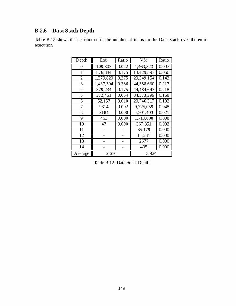
B.2.6 Data Stack Depth
Table B.12 shows the distribution of the number of items on the Data Stack over the entireexecution.
Depth Ext. Ratio VM Ratio
0 109,303 0.022 1,469,323 0.0071 876,384 0.175 13,429,593 0.0662 1,379,820 0.275 29,249,154 0.1433 1,437,394 0.286 44,388,630 0.2174 879,234 0.175 44,484,643 0.2185 272,451 0.054 34,373,299 0.1686 52,157 0.010 20,746,317 0.1027 9314 0.002 9,725,059 0.0488 2184 0.000 4,301,403 0.0219 463 0.000 1,710,608 0.00810 47 0.000 367,851 0.00211 - - 65,179 0.00012 - - 11,231 0.00013 - - 2677 0.00014 - - 405 0.000
Average 2.636 3.924
Table B.12: Data Stack Depth
149

B.2.7 Return Stack Depth
Table B.13 shows the distribution of the usage of the Return Stack over the entire execution.The depth of the Return Stack is usually equal to the call depth of the program, plus sometransient, temporary storage.
Depth Ext. Ratio VM Ratio
0 5666 0.001 19,823 0.0001 1,862,081 0.371 8,362,538 0.0412 1,452,360 0.289 15,583,345 0.0763 1,147,591 0.229 57,244,617 0.2804 379,797 0.076 48,202,927 0.2365 169,104 0.034 44,737,258 0.2196 1978 0.000 17,140,510 0.0847 174 0.000 10,796,692 0.0538 - - 1,452,808 0.0079 - - 778,445 0.00410 - - 6079 0.00011 - - 330 0.000
Average 2.110 4.037
Table B.13: Return Stack Depth
150

Bibliography
[ABB64] G. M. Amdahl, G. A. Blaauw, and F. P. Brooks,Architectureof theIBM System360, IBM Journal of Research and Development8 (1964), no. 2, 87–101.
[All85] Murray W Allen, CharlesHamblin (1922-1985), Aust. Comput. J.17 (1985),no. 4, 194–195.
[Bai94] Chris Bailey,HLL enhancementfor stackbasedprocessors, EuroMicro Journalof Microprocessing and Microprogramming40 (1994), 665–668.
[Bai96] , Optimisation Techniques for Stack-Based Processors, PhD thesis, Uni-versity of Teesside, UK, July 1996, Amongst other things, analyzes the use ofstack buffers to reduce memory traffic.
[Bai00] , Achievingminimalanddeterministicinterruptexecutionin stack-basedprocessorarchitectures., inEUROMICRO [DBL00], pp. 1368–.
[Bai04] , A proposedmechanismfor super-pipelinedinstruction-issuefor ilpstackmachines, DSD ’04: Proceedings of the Digital System Design, EUROMI-CRO Systems on (DSD’04) (Washington, DC, USA), IEEE Computer Society,2004, pp. 121–129.
[Bar61a] R. S. Barton,A new approachto the functional designof a digital computer,AFIPS Conference Proceedings19 (1961), 393–396, presented at IRE-AIEE-ACM Computer Conference, May 9-11, 1961.
[Bar61b] , Systemdescriptionfor an improvedinformationprocessingmachine,Proceedings of the 1961 16th ACM national meeting (New York,NY, USA),ACM Press, 1961, pp. 103.101–103.104.
[Bar61c] Robert S. Barton,Functionaldesignof computers, Commun. ACM4 (1961),no. 9, 405.
[Bar87] R. S. Barton,A newapproachto thefunctionaldesignof adigital computer, IEEEAnnals of the History of Computing09 (1987), no. 1, 11–15.
[Bau60] Friedrich L. Bauer,The formula-controlledlogical computer"STANISLAUS",Math. Tabl. Aids Comp14 (1960), 64–67.
151

[Bau90] F. L. Bauer,Thecellar principle of statetransitionandstorageallocation, IEEEAnn. Hist. Comput.12 (1990), no. 1, 41–49.
[Bau02] Friedrich L. Bauer,From the Stack Principle to ALGOL, pp. 26–42, in Broy andDenert [BD02], 2002, Points to possible earlier origins of stacks for computation.
[BBG+60] J. W. Backus, F. L. Bauer, J. Green, C. Katz, J. McCarthy, A. J. Perlis,H. Rutishauser, K. Samelson, B. Vauquois, J. H. Wegstein, A.van Wijngaar-den, and M. Woodger,ReportonthealgorithmiclanguageALGOL 60, Commun.ACM 3 (1960), no. 5, 299–314.
[BBRS58] F. L. Bauer, H. Bottenbruch, H. Rutishauser, and K.Samelson,Proposalfor auniversallanguagefor the descriptionof computingprocesses, pp. 355–373, inCarr [Car58], 1958.
[BCM+70] G. Bell, R. Cody, H. McFarland, B. DeLagi, J. O’Laughlin,R. Noonan, andW. Wulf, A newarchitecturefor mini-computers:theDECPDP-11, Proc. AFIPSSJCC (1970), 657–675.
[BD02] Manfred Broy and Ernst Denert (eds.),Software pioneers: contributions tosoftwareengineering, Springer-Verlag New York, Inc., New York, NY,USA,2002.
[BFPB97] Gerrit A. Blaauw and Jr. Frederick P. Brooks,Computerarchitecture:Conceptsand evolution, Addison-Wesley Longman Publishing Co., Inc., Boston, MA,USA, 1997.
[BI86] Leo B. Brodie and FORTH Inc.,StartingFORTH, second ed., Prentice-Hall, Inc.,Upper Saddle River, NJ, USA, 1986.
[Bla77] Russell P. Blake,Exploringastackarchitecture, Computer10 (1977), no. 5, 30–39, QA76.5.I54, not in ACM Digital Library.
[Bla90] Mario De Blasi,Computerarchitecture, Addison-Wesley Longman PublishingCo., Inc., 1990.
[Bro84] Leo B. Brodie, Thinking FORTH: a languageand philosophy for solvingproblems, Prentice-Hall, Inc., Upper Saddle River, NJ, USA, 1984.
[BSa] Friedrich Ludwig Bauer and Klaus Samelson,Frenchpatent1.204.424:Machineà calculerautomatiqueet procédépoursonexploitation, Filed March 28, 1958.Delivered August 10, 1959. Published January 26, 1960.
[BSb] , Gb patent 892,098: Improvementsin and relating to computingmachines, Filed March 31, 1958. Published MArch 21, 1962.
[BSc] , Germanpatent1 094 019: Verfahrenzur automatischenVerarbeitungvon kodiertenDatenund Rechenmaschinezur AusübungdesVerfahrens, FiledMarch 30, 1957. Granted December 1, 1960.
152
[BSd] , Us patent3,047,228:Automaticcomputingmachinesand methodofoperation, Filed March 28, 1958. Granted July 31, 1962.
[BS94] C. Bailey and R. Sotudeh,HLL enhancementfor stackbasedprocessors, Selectedpapers of the short notes session on Euromicro ’94 (Amsterdam, The Netherlands,The Netherlands), Elsevier Science Publishers B. V., 1994,pp. 685–688.
[Bul77] D. M. Bulman,Stackcomputers, Computer10 (1977), no. 5, 14–16.
[Bur63] Burroughs Corporation, Detroit, Michigan,Operationalcharacteristicsof theprocessorsfor theBurroughsB5000, 1963, Pub. No. 5000-21005, Revision A.
[Bur67] Burroughs Corporation, Detroit, Michigan,Burroughs B5500 informationprocessingsystemsreferencemanual, May 1967, Pub. No. 1021326.
[Bur73] Burroughs Corporation, Detroit, Michigan,B7700 systemsreferencemanual,1973, Form 1060233.
[Bur81] Burroughs Corporation, Detroit, Michigan,B6900systemreferencemanual, July1981, Form 5100986.
[Bur98] Stephen D. Burd,Systemsarchitecture:Hardwareandsoftwarein informationsystems, South-Western Publishing Company, 1998.
[Car58] J. W. Carr (ed.),Summerschool1958, University of Michigan, 1958.
[Cha95] Robert James Chapman,Stack quarks, Proc. Rochester Forth Con-ference on Emerging Technology (Rochester, New York) (LawrenceP. G. Forsley, ed.), University of Rochester, The Institutefor AppliedForth Research, Inc., June 1995, Decomposes the typical stack per-mutation operations into smaller primitives. Online as of Nov. 2006:http://www.compusmart.ab.ca/rc/Papers/StackQuarksPaper.pdf.
[Cha97] , A writable computer, Proc. Rochester Forth Conference on EmergingTechnology (Rochester, New York) (Lawrence P. G. Forsley, ed.), Universityof Rochester, The Institute for Applied Forth Research, Inc., June 1997, De-scribes the VHDL design of a small stack computer. Online as of Nov. 2006:http://www.compusmart.ab.ca/rc/Papers/writablecomputer.pdf.
[Cha98] Rob Chapman, A Stack Processor: Synthesis, web page, Jan-uary 1998, Project Report for EE602. Online as of Nov. 2006:http://www.compusmart.ab.ca/rc/Papers/spsynthesis.pdf.
[Chu75] Yaohan Chu,High-level languagecomputerarchitecture, Academic Press, Inc.,Orlando, FL, USA, 1975.
[DBL00] 26th EUROMICRO 2000 conference,informatics: Inventing the future, 5-7september2000,Maastricht,TheNetherlands, IEEE Computer Society, 2000.
153

[Dor75a] R. W. Doran,The InternationalComputersltd. ICL2900 computerarchitecture,SIGARCH Comput. Archit. News4 (1975), no. 3, 24–47.
[Dor75b] Robert W. Doran,Architectureof stackmachines, pp. 63–108, in [Chu75], 1975.
[DP80] David R. Ditzel and David A. Patterson,Retrospectiveon high-level languagecomputerarchitecture, ISCA ’80: Proceedings of the 7th annual symposium onComputer Architecture (New York, NY, USA), ACM Press, 1980,pp. 97–104.
[DP86] , Retrospectiveon high-levellanguagecomputerarchitecture, pp. 44–51,in [FL86], 1986.
[DP98a] , Retrospective: a retrospectiveon high-level language computerarchitecture, ISCA ’98: 25 years of the international symposia on Computer ar-chitecture (selected papers) (New York, NY, USA), ACM Press, 1998, pp. 13–14.
[DP98b] , Retrospectiveon high-levellanguagecomputerarchitecture, ISCA ’98:25 years of the international symposia on Computer architecture (selected papers)(New York, NY, USA), ACM Press, 1998, pp. 166–173.
[Dun77] Fraser George Duncan,Stackmachinedevelopment:Australia,greatbritain,andeurope, Computer10 (1977), no. 5, 50–52.
[Eng63] English Electric-LEO Computers Ltd., Kidsgrove, Stoke-On-Trent, Staffordshire, England, KDF9 programming manual, circa1963, Online as of March 2006 at: http://www.jeays.ca/kdf9.htmland http://frink.ucg.ie/~bfoley/edhist/kdf9pm/kdf9pm.html andhttp://acms.synonet.com/deuce/KDF9pm.pdf.
[FL86] Eduardo B. Fernandez and Tomas Lang,Software-oriented computerarchitecture, IEEE Computer Society Press, Los Alamitos, CA, USA, 1986.
[Fox98] Jeff Fox, F21 CPU, web page, 1998, Online as of April 2007:http://ultratechnology.com/f21.html.
[Fox04] , Forth Chips, web page, 2004, Online as of April 2007:http://ultratechnology.com/chips.htm.
[FR93] James M. Feldman and Charles Retter,Computerarchitecture;a designer’stextbasedon agenericRISC, McGraw-Hill, Inc., 1993.
[Fre98] Paul Frenger,Forth in space,or, so NEAR yet so far out, SIGPLAN Not.33(1998), no. 6, 24–26.
[Fre01] , Closeencountersof the Forth kind, SIGPLAN Not.36 (2001), no. 4,21–24.
[GL03] William F. Gilreath and Phillip A. Laplante,Computer Architecture, Kluwer Aca-demic Publishers, 2003.
154

[GWS91] II George William Shaw,Sh-BOOM: the soundof the RISC marketchanging,Proceedings of the second and third annual workshops on Forth, ACM Press,1991, p. 125.
[Hal62] A. C. D. Haley,TheKDF.9computersystem, Proceedings of the AFIPS Fall JointComputer Conference, vol. 21, 1962, pp. 108–120.
[Ham57a] Charles L. Hamblin,An addresslesscoding schemebasedon mathematicalnotation, Proceedings of the First Australian Conference on Computing and DataProcessing (Salisbury, South Australia: Weapons ResearchEstablishment), Jun1957.
[Ham57b] , Computerlanguages, The Australian Journal of Science20(1957), 135–139.
[Ham85] , Computerlanguages, Aust. Comput. J.17 (1985), no. 4, 195–198,Reprint of 1957 paper in volume 20 of The Australian Journal of Science.
[Hay97] John P. Hayes,Computerarchitectureandorganization, McGraw-Hill, Inc., 1997.
[Hen84] John L. Hennessy,VLSI processorarchitecture, IEEE Transaction on ComputersC-33 (1984), no. 12, 1221–1246.
[Hen86] , VLSI processorarchitecture, pp. 90–115, in [FL86], 1986.
[Hew84] Hewlett-Packard, Cupertino, California,HP 3000 computersystemsgeneralinformationmanual, October 1984, Pub. No. 5953-7983.
[HH00] Richard E. Haskell and Darrin M. Hanna,Implementing a Forth enginemicrocontrolleron aXilinx FPGA, Looking Forward – The IEEE Computer So-ciety’s Student Newsletter (A Supplement to Computer)8 (2000), no. 1, Onlineas of Nov. 2006: http://www.cse.secs.oakland.edu/hanna/research/IEEE2.pdf andhttp://www.cse.secs.oakland.edu/haskell/VHDL/IEEEStudent.PDF.
[HJB+82] John Hennessy, Norman Jouppi, Forest Baskett, Thomas Gross, and John Gill,Hardware/softwaretradeoffsfor increasedperformance, ASPLOS-I: Proceedingsof the first international symposium on Architectural support for programminglanguages and operating systems (New York, NY, USA), ACM Press, 1982,pp. 2–11.
[HJP+82] John Hennessy, Norman Jouppi, Steven Przybylski, Christopher Rowen, ThomasGross, Forest Baskett, and John Gill,MIPS: A microprocessorarchitecture, MI-CRO 15: Proceedings of the 15th annual workshop on Microprogramming (Pis-cataway, NJ, USA), IEEE Press, 1982, pp. 17–22.
[HP96] John L. Hennessy and David A. Patterson,Computerarchitecture:A quantitativeapproach, 2nd ed., Morgan Kaufmann Publishers Inc., 1996, The dominant text-book on current computer architecture, which I’ve found to be erroneous withregards to current stack architecture.
155
[HP02] , Computerarchitecture: A quantitativeapproach, Morgan KaufmannPublishers Inc., 2002.
[HVZ95] V. Carl Hamacher, Zvonko G. Vranesic, and Safwat G. Zaky, Computerorganization, McGraw-Hill Higher Education, 1995.
[Hwa92] Kai Hwang, Advanced computer architecture: Parallelism, scalability,programmability, McGraw-Hill Higher Education, 1992.
[IC78] R. N. Ibbett and P. C. Capon,The developmentof the MU5 computersystem,Commun. ACM21 (1978), no. 1, 13–24.
[Int00] Intersil,Datasheetfor HS-RTX2010RH, March 2000, File Number 3961.3.
[Int06] Intel Corporation, Dever, CO,Intel R© 64 and IA-32 architecturesoptimizationreferencemanual, November 2006, Order Number: 248966-014.
[Kat85] Manolis G. H. Katevenis,Reducedinstructionset computerarchitecturesforVLSI, Massachusetts Institute of Technology, Cambridge, MA, USA, 1985, Oneof the PhD theses from the Berkeley RISC project. Goes into the deep technicaldetails and reasonnings behind RISC.
[KDF61] KDF9: Very high speeddataprocessingsystemfor commerce,industry,science,English Electric, Kidsgrove, Stoke-On-Trent, Staffordshire, England, 1961, Salesbrochure for the KDF9.
[KKC92a] William F. Keown, Philip Koopman, and Aaron Collins, Performanceof theHarris RTX 2000 stack architectureversusthe Sun 4 SPARC and the Sun 3M68020architectures, SIGARCH Comput. Archit. News20(1992), no. 3, 45–52.
[KKC92b] , Real-timeperformanceof theHarrisRTX 2000stackarchitectureversustheSun4 SPARCandtheSun3 M68020architectureswith aproposedreal-timeperformancebenchmark, SIGMETRICS Perform. Eval. Rev.19 (1992), no. 4,40–48.
[Kog90] Peter M. Kogge,The architectureof symbolic computers, McGraw-Hill, Inc.,1990.
[Koo89] Philip J. Koopman,Stackcomputers:thenewwave, Halsted Press, 1989, A com-pendium of stack computer architectures. Has useful experimental data.
[Koo90] , Modernstackcomputerarchitecture, System Design and Network Ar-chitecture Conference (1990), 153–164.
[Koo91] , Someideasfor stack computerdesign, Rochester Forth Conference(1991), 58.
[Koo94] , A preliminaryexplorationof optimizedstackcodegeneration, Journalof Forth Applications and Research6 (1994), no. 3, 241–251.
156
[Lav80] Simon Hugh Lavington,Earlybritishcomputers:Thestoryof vintagecomputersand the peoplewho built them, Butterworth-Heinemann, Newton, MA, USA,1980.
[LTL98] P. H. W. Leong, P. K. Tsang, and T. K. Lee,A FPGAbasedforth microprocessor,FCCM ’98: Proceedings of the IEEE Symposium on FPGAs for Custom Com-puting Machines (Washington, DC, USA), IEEE Computer Society, 1998, p. 254.
[Luk29] Jan Lukasiewicz,Elementsof mathematicallogic, Warsaw, 1929, [English trans-lation of 1958 edition: Macmillan, 1963].
[McK80] William M. McKeeman,Stackcomputers, pp. 319–362, in [Sto80], 1980.
[McL93] Edward McLellan,TheAlpha AXP architectureand21064processor, IEEE Mi-cro 13 (1993), no. 3, 36–47.
[ME97] Martin Maierhofer and M. Anton Ertl,Optimizing stack code, Forth-Tagung1997, 1997.
[ME98] , Local stackallocation, Compiler Construction 1998, Springer LNCS1383, 1998, pp. 189–203.
[MK97] M. Morris Mano and Charles R. Kime,Logic andcomputerdesignfundamentals,Prentice-Hall, Inc., 1997.
[ML70] Charles H. Moore and Geoffrey C. Leach,FORTH – a languagefor interactivecomputing, Mohasco Industries, Inc., Amsterdam, NY, 1970,Internal publica-tion.
[Moo91] Charles H. Moore,Forth - the early years, Unpublished notes that becamethe papers by Rather, Colburn, and Moore [RCM93] [RCM96]. Accesible athttp://www.colorforth.com/HOPL.html as of Nov. 2006., 1991.
[Moo01a] , 25x emulator, Proceedings of the 17th EuroForth Conference(SchlossDagstuhl, Saarland, Germany), University of Teesside, November 2001, ISBN: 0907550 97 6.
[Moo01b] , c18 colorForth compiler, Proceedings of the 17th EuroForthConference(Schloss Dagstuhl, Saarland, Germany), University of Teesside, November 2001,One of the few published papers by Chuck Moore. Describes thec18 instructionset in detail.
[MP95] Silvia M. Muller and Wolfgang J. Paul,The complexity of simple computerarchitectures, Springer-Verlag New York, Inc., 1995.
[MT95] Charles H. Moore and C. H. Ting,MuP21– aMISC processor, Forth Dimensions(1995), 41, http://www.ultratechnology.com/mup21.html.
[Mur86] Robert W. Murphy,Underthehoodof asuperchip:theNOVIX Forthengine, J.FORTH Appl. Res.3 (1986), no. 2, 185–188.
157

[Mur90] William D. Murray,Computeranddigital systemarchitecture, Prentice-Hall, Inc.,1990.
[Omo94] Amos R. Omondi,Computerarithmeticsystems:algorithms,architectureandimplementation, Prentice Hall International (UK) Ltd., 1994.
[Omo99] , Themicroarchitectureof pipelinedandsuperscalarcomputers, KluwerAcademic Publishers, 1999.
[Org73] Elliott Irving Organick,Computersystemorganization:TheB5700/B6700 series(ACM monographseries), Academic Press, Inc., Orlando, FL, USA, 1973.
[Pat85] David A. Patterson,Reducedinstruction set computers, Commun. ACM28(1985), no. 1, 8–21.
[Pat86] , Reducedinstructionsetcomputers, pp. 76–89, in [FL86], 1986.
[Pay96] Bernd Paysan,Implementationof the 4stackprocessorusingVerilog, Diplomathesis, Technische Universitat Munchen, Institut fur Informatik, August 1996,http://www.jwdt.com/~paysan/4stack.html.
[Pay02] Berndt Paysan,b16–AForthprocessorin anFPGA, Forth-Tagung 2002 (2002),http://www.b16-cpu.de/.
[PD80] David A. Patterson and David R. Ditzel,Thecasefor thereducedinstructionsetcomputer, SIGARCH Comput. Archit. News8 (1980), no. 6, 25–33.
[PH90] David A. Patterson and John L. Hennessy,Computerarchitecture:aquantitativeapproach, Morgan Kaufmann Publishers Inc., 1990.
[PH98] , Computerorganizationanddesign:thehardware/softwareinterface, 2nded., Morgan Kaufmann Publishers Inc., 1998.
[PS81] David A. Patterson and Carlo H. Sequin,RISC I: A reducedinstructionsetVLSIcomputer, ISCA ’81: Proceedings of the 8th annual symposiumon ComputerArchitecture (Los Alamitos, CA, USA), IEEE Computer Society Press, 1981,pp. 443–457.
[PS98a] David A. Patterson and Carlo H. Séquin,Retrospective:RISC I: areducedinstructionsetcomputer, ISCA ’98: 25 years of the international symposia onComputer architecture (selected papers) (New York, NY, USA), ACM Press,1998, pp. 24–26.
[PS98b] David A. Patterson and Carlo H. Sequin,RISC I: a reducedinstructionsetVLSIcomputer, ISCA ’98: 25 years of the international symposia on Computer archi-tecture (selected papers) (New York, NY, USA), ACM Press, 1998, pp. 216–230.
158

[Ras03] James Rash, Space-related applications of forth, webpage:http://forth.gsfc.nasa.gov/, April 2003, Presents space-related applicationsof Forth microprocessors and the Forth programming language at NASA.Accessed on Nov. 2006.
[RCM93] Elizabeth D. Rather, Donald R. Colburn, and CharlesH. Moore,TheevolutionofForth, The second ACM SIGPLAN conference on History of programming lan-guages (Cambridge, Massachusetts, United States), ACM Press, 1993, pp. 177–199.
[RCM96] , The evolutionof Forth, History of programming languages—II (NewYork, NY, USA), ACM Press, 1996, pp. 625–670.
[Ros87] Robert F. Rosin,Prologue:TheBurroughsB5000, Annals of the History of Com-puting9 (1987), no. 1, 6–7.
[SB60] K. Samelson and F. L. Bauer,Sequentialformula translation, Commun. ACM3(1960), no. 2, 76–83.
[SB04] Huibin Shi and Chris Bailey,Investigatingavailableinstructionlevel parallelismfor stackbasedmachinearchitectures, DSD ’04: Proceedings of the Digital Sys-tem Design, EUROMICRO Systems on (DSD’04) (Washington, DC,USA), IEEEComputer Society, 2004, pp. 112–120.
[Sha99] George William Shaw,PSC1000microprocessorreferencemanual, Patriot Sci-entific Corporation, San Diego, CA, March 1999, Ref. No. 99-0370001.
[Sha02] , IGNITE intellectualpropertyreferencemanual, Patriot Scientific Cor-poration, San Diego, CA, March 2002, Revision 1.0.
[Sit78] Richard L. Sites,A combinedregister-stackarchitecture, SIGARCH Comput.Archit. News6 (1978), no. 8, 19–19.
[SSK97] Dezso Sima, D. Sima, and Peter Kacsuk,Advancedcomputerarchitectures,Addison-Wesley Longman Publishing Co., Inc., 1997.
[Sta90] William Stallings,Computerorganizationandarchitecture, 2nd ed., Prentice HallPTR, 1990.
[Sta93] , Computerorganizationand architecture: principles of structureandfunction, 3rd ed., Macmillan Publishing Co., Inc., 1993.
[Sta02] , Computerorganizationand architecture, Prentice Hall ProfessionalTechnical Reference, 2002.
[Sto80] Harold S. Stone,Introductionto computerarchitecture, Science Research Asso-ciates, 1980.
[Sto92] , High-performancecomputerarchitecture, Addison-Wesley LongmanPublishing Co., Inc., 1992.
159

[TCCLL99] P.K. Tsang, K.H. C.C. Cheung, T.K. Lee Leung, and P.H.W. Leong,MSL16A: an asynchronous Forth microprocessor, TENCON 99. Proceedings ofthe IEEE Region 10 Conference, vol. 2, September 1999, pp. 1079–1082.
[Tin97a] C H Ting,The P seriesof microprocessors, More On Forth Engines22 (1997),1–17.
[Tin97b] , P16 microprocessordesign in VHDL, More On Forth Engines22(1997), 44–51.
[Wil91] Barry Wilkinson, Computerarchitecture: Design and performance, 1st ed.,Prentice-Hall, Inc., 1991.
[Wil96] , Computerarchitecture:Designandperformance, 2nd ed., Prentice-Hall,Inc., 1996.
[Wil01] Rob Williams, Computersystemsarchitecturewith CDROM, Addison-WesleyLongman Publishing Co., Inc., 2001.
[Yue] C K Yuen, Superscalarexecution of stack programsusing reorder buffer,http://www.comp.nus.edu.sg/~yuenck/stack.
160