sec 5 - engineering design standards revised jan...
TRANSCRIPT

October 1, 2009 (Revised January, 2010)
CITY OF PALM COAST TECHNICAL MANUAL
SECTION V
DDeessiiggnn SSttaannddaarrddss
Effective November 16, 2008
ENGINEERING

CITY OF PALM COAST TECHNICAL MANUAL
ENGINEERING DESIGN STANDARDS
Table of Contents V-i October 1, 2009 (Revised January, 2010)
TABLE OF CONTENTS Description SECTION 100 COMMUNICATION CONDUIT FOR FIBER OPTICS 1 Section 100.01 Scope of Standard 1 Section 100.02 Design Guidelines 1 Section 100.03 Reference Standards 1 Section 100.04 Codes, Standards, References, and Applicability 2 Section 100.05 Definitions 3 Section 100.06 Guidelines for Designing Underground Fiber Optic Cable Routes 4 Section 100.07 Guidelines for Installing / Pulling Underground Fiber Optic Cable 6 Section 100.08 Guidelines for Installing Conduit 6 Section 100.09 Safety 7 Section 100.10 Locating Fiber Optic Cables 7 SECTION 200 STORMWATER 8 Section 200.01 Stormwater Design Criteria 8 Drawing # 200.A Typical Lot Grading 9 Drawing # 200.B Open Road Cuts / Compacted Fill 10 Drawing # 200.C Open Road Cuts / Flowable Fill 11 Drawing # 200.D Curb and Gutter Typical Construction Detail 12 Section 200.02 Structural Soil Mix Specifications 13 Section 200.03 Lake and Pond Construction Requirements 13 Drawing # 200.E Retention (Wet) Typical Detail 14 SECTION 300 STORMWATER PERMIT REQUIREMENTS 15 Section 300.01 Residential Lot Application (Unimproved Properties) 15 Section 300.02 Residential Pool 18 Section 300.03 Lot Grading Permit Requirements (Improved Properties) 20 Section 300.04 Lot Grading Permit Requirements for Vacant Lots 22 Section 300.05 Beautification Right-of-Way 25 Drawing # 300.A Sample of Beautification of the Right-of-Way Plan 25 Drawing # 300.B Sample General Right-of-Way Access Permit (Residential Properties) 26 Drawing # 300.C Sample Swale Plan 27 Drawing # 300.D Typical Residential Swale Profile 28 Drawing # 300.E Residential Culvert Detail 29 Drawing # 300.F Residential Cul-de-sac Swale Profile 30 Drawing # 300.G Residential Culvert Paver Driveway Detail 31 Drawing # 300.H Residential Culvert Paver Driveway Supplement 32 SECTION 400 DRIVEWAY AND SIDEWALKS 33 Section 400.01 Driveways 33 Drawing # 400.A Illustrations of Good or Acceptable Design Practice 33 Section 400.02 Sidewalks 34 SECTION 500 PARKING 34
Section 500.01 Off-Site Parking 34 Section 500.02 On-Street Parking 34 Section 500.03 Calculated Shared Parking Reduction 34 Table 5-9 Shared Parking Usage Percentages for Mixed-Use Developments 35 Table 5-10 Shared Parking Matrix Examples 35
Drawing # 500.A Parking Diagram and Dimensional Requirements 36

Table of Contents V-ii October 1, 2009 (Revised January, 2010)
CITY OF PALM COAST TECHNICAL MANUAL ENGINEERING DESIGN STANDARDS
TABLE OF CONTENTS SECTION 600 PLATS AND SURVEYS 38
Section 600.01 Horizontal and Vertical Control 38 Section 600.02 Monumentation 38 Section 600.03 Plat Surety Letter of Credit 39 Section 600.04 Plat Surety Performance Bond 41 Section 600.05 Developer’s Maintenance Bond for (type) Work 43
SECTION 700 ROADWAY CLASSIFICATIONS 45
Drawing # 700.A Cul-de-sac Details 45 Drawing # 700.B 50’ Right-of-Way Detail 46 Drawing # 700.C 60’ Right-of-Way Tree Planting Cross Section 47 Drawing # 700.D 60' Right-of-Way Tree Planting Plan View 48 Drawing # 700.E Residential Cul-de-sac Cross-section Detail for Street Tree Planting 49
SECTION 800 SITE DEVELOPMENT 50
Section 800.01 Engineer’s Construction Permit Summary 50 Section 800.02 Engineer’s Site Plan Review Checklist 51 Section 800.03 Site Development Fee Calculation Sheet 52 Section 800.04 Preconstruction Meeting Requests 54 Section 800.05 Site Inspection Requirements 55 Section 800.06 Final Inspection Checklist 56 Section 800.07 Construction Inspections – Engineer’s Certificate of Completion 57 Section 800.08 Standard Requirements for Paving and Drainage Record Drawings 58 Section 800.09 Bill of Sale 59
SECTION 900 RIGHT-OF-WAY (ROW) UTILIZATION PERMITS 60
Section 900.01 Right-of-Way Utilization Permit Procedures 60 Section 900.02 References 60 Section 900.03 Location Standards: Utility Installations 61 Section 900.04 Driveways 62 Section 900.05 Permit Application 63 Section 900.06 Utility or Stormwater Crossings 64 Section 900.07 Construction Standards 65 Section 900.08 Testing 66 Section 900.09 Inspection 67 Section 900.10 Working Hours 67 Section 900.11 Maintenance of Traffic 68 Section 900.12 Landscaping and Irrigation Systems 68 Section 900.13 Right-of-Way Permit Application Information Sheet 70 Section 900.14 Sample Right-of-Way Utilization Permit (Commercial) 71
SECTION 1000 TRAFFIC 73
Section 1000.01 Street Name Signs at Signalized Intersections 73 Section 1000.02 Street Name Signs at Non-Signalized Intersections 74 Section 1000.03 Traffic Signal Controller 75 Section 1000.04 Mast Arm Construction 75 Section 1000.05 Pavement Markings 76 Section 1000.06 One-Way Street Intersection Signage 76 Section 1000.07 Street Lights 77 Section 1000.08 Traffic General Notes 78 Section 1000.09 Radio Activated, GPS Based Traffic Signal Priority Control System 78

CITY OF PALM COAST TECHNICAL MANUAL ENGINEERING DESIGN STANDARDS
Table of Contents V-iii October 1, 2009 (Revised January, 2010)
TABLE OF CONTENTS
SECTION 1100 PRESERVATION AND PROTECTION OF SHORES AND CHANNELS 89 Section 1100.01 Control of Shores and Channels 89 Section 1100.02 Reservation of Rights 89 Section 1100.03 Use of Waterways 89 Section 1100.04 Piers and Related Structures 90 Section 1100.05 Mooring and Storage of Watercraft 90 Section 1100.06 Saltwater Canals 91
Drawing # 1100.A Saltwater Canal Typical Seawall 91 Drawing # 1100.B Saltwater Canal Typical Bulkhead 92 Drawing # 1100.C Saltwater Canal Typical Revetment (Rip Rap) 92 Drawing # 1100.D Saltwater Canal Typical Undisturbed Bank 93
Section 1100.07 Tidal Datum for Palm Coast 93 Section 1100.08 Dredging 94 Section 1100.09 Seawalls / Bulkheads and Revetments 94
Drawing # 1100.E Saltwater Canal Typical Seawall Profiles 94 Drawing # 1100.F Saltwater Canal Typical Bulkhead Profile 94 Drawing # 1100.G Saltwater Canal Typical Seawall/ Bulkhead End Return Detail 95
Drawing # 1100.H Typical Saltwater Canal Revetment (Rip Rap) Profile 96 Drawing # 1100.I Typical Intracoastal Waterway Revetment (Rip Rap) Profile 96 Section 1100.10 Seawall / Bulkhead / Revetment Construction Permit Requirements 97 Drawing # 1100.J Saltwater Canal Typical Seawall Grading Plan 97 Section 1100.11 Seawall / Bulkhead / Revetment Construction Permit Conditions 97 Drawing # 1100.K Topographic Survey with Sample Barrier Plan 98 Section 1100.12 Docks on Saltwater Canals 99 Drawing # 1100.L Saltwater Canal Typical Corner Dock Allocation 100 Drawing # 1100.M Saltwater Canal Seawall Dock 101 Drawing # 1100.N Saltwater Canal Bulkhead Dock 101 Table # 1100.A Saltwater Canal Roof Structure Diagram 101 Section 1100.12.1 Floating Docks on Saltwater Canals 102 Section 1100.12.2 Dock Lifts on Saltwater Canals 102 Section 1100.12.3 Cantilevered Safety Walks on Saltwater Canals 102
Section 1100.13 Docks on Intracoastal Waterway 102 Section 1100.14 Freshwater Canals 103 Drawing # 1100.P Docks on Freshwater Canals 103 SECTION 1200 EROSION CONTROL 105
Section 1200.01 Silt Fences / Floating Turbidity Barriers 105 Drawing # 1200.A Silt Fence Example 105 Drawing # 1200.B Floating Turbidity Barrier Example 106 SECTION 1300 CAPITAL PROJECTS – CITY OF PALM COAST 107
Section 1300.01 Construction Information Signs 107 Drawing # 1300.A Sample Construction Sign 107
Section 1300.02 Monument Sign for City Facilities 107 Drawing # 1300.B Sample Monument Sign 107

11 V-1 October 1, 2009 (Revised January, 2010)
CITY OF PALM COAST TECHNICAL MANUAL ENGINEERING DESIGN STANDARDS
These guidelines identify and define the City of Palm Coast requirements and policies for designing and installing telecommunications infrastructure and substructure at all City of Palm Coast facilities. Use of, and compliance with these guidelines is mandatory for architects, engineers, and installation contractors working on City of Palm Coast projects. A. The City of Palm Coast Infrastructure Standards are based upon the code requirements and
telecommunications industry standards contained in the following guidelines. These guidelines will not duplicate the information contained in those references, except where necessary to provide guidance, clarification or direction.
B. In instances where several technical alternatives may be available to provide a design solution,
these guidelines will identify the preferred solution to meet City of Palm Coast needs. However, each facility and project is unique. Design for new construction will differ from design for retrofit of existing facilities. These guidelines will differentiate certain design approaches and solutions to be applied to new construction versus existing facilities, and different types of City of Palm Coast facilities. However, designers and installers shall always use sound engineering judgment in order to comply with the requirements of the codes and standards identified in this section.
A. Adherence to, and compliance with, the codes and standards referenced, and the City of Palm
Coast unique requirements and design solutions identified in the manual, is mandatory. Requests to deviate from the industry standards and design solutions prescribed in these guidelines may be submitted, on a case-by-case basis, to the City Engineer for review and approval. No deviation from the requirements of the National Electrical Code will be allowed.
B. Architects, Consultants, and Contractors shall always reference the most recent standards
available. Most references listed below can be purchased directly from the individual standards organization, or from: Global Engineering Documents Inverness Way East Englewood, CO 80112-5776 Telephone: (800) 854-7179 (303) 397-7956 Fax: (303) 397-2740 http://www.global.ihs.com
Section 100.01 Scope of Standard
Section 100.02 Design Guidelines
Section 100.03 Reference Standards
SECTION 100 COMMUNICATION CONDUIT FOR FIBER OPTICS

22 V-2 October 1, 2009 (Revised January, 2010)
CITY OF PALM COAST TECHNICAL MANUAL ENGINEERING DESIGN STANDARDS
A. NATIONAL ELECTRICAL CODE, NFPA 70 The National Fire Protection Association has acted as the sponsor of the National Electrical
Code (NEC) since 1911. The original Code was developed in 1897 as a result of the united efforts of various insurance, electrical, architectural, and allied interests. The purpose of the NEC is the practical safeguarding of persons and property from hazards arising from the use of electricity. The NEC provides the minimum code requirements for electrical safety. In telecommunications distribution design, the NEC must be used in concert with the ANSI/EIA/TIA standards identified below, which are intended to insure the performance of the telecommunications infrastructure.
B. ANSI/TIA/EIA STANDARDS The Telecommunications Industry Association/Electronics Industry Association (TIA/EIA)
engineering standards and publications are designed to serve the public interest through eliminating misunderstandings between manufacturers and purchasers. The standards facilitate interchangeability and improvement of products and assist the purchaser in selecting and obtaining the proper product for his or her particular need.
The TIA/EIA Standards are updated every five years. Due to the rapid changes in the
telecommunications and electronics industries, TIA/EIA publishes periodic Telecommunications Systems Bulletins (TSB), which provides additional guidance on certain technical issues that must be addressed prior to the next scheduled revision of the standards. The information contained in TSBs is usually incorporated into the applicable standard during the next standards revision. Standards and publications are adopted by TIA/EIA in accordance with American National Standards Institute (ANSI) patent policy. The TIA web site is: http://www.tiaonline.org/
C. FIBER OPTIC TEST STANDARDS, TIA/EIA-526 (SERIES) The TIA/EIA-455 series, together with its addenda, provides uniform test procedures for testing
the fiber optic components intended for, or forming a part of, optical communications and data transmission systems. This series contains standard test procedures for optical fibers, cables, transducers, and connecting and terminating devices.
D. CABLING STANDARD, ANSI/TIA/EIA-568 (SERIES)
The ANSI/TIA/EIA-568-A (series) is the Commercial Building Telecommunications Cabling Standard. This standard defines a generic telecommunications wiring system for commercial buildings that will support a multiproduct, multivendor environment. It also provides direction for the design of telecommunications products for commercial enterprise. The purpose of the standard is to enable planning and installation of building wiring with little knowledge of the telecommunications products that subsequently will be installed. Installation of wiring systems during building construction or renovation is significantly less expensive and less disruptive than after the building is occupied. TIA/EIA-568-A establishes performance and technical criteria for various wiring system configurations for interfacing and connecting their respective elements.
E. GROUNDING AND BONDING, ANSI/TIA/EIA-607 (SERIES) The ANSI/TIA/EIA-606 (series) is the Commercial Building Grounding and Bonding
Requirements for Telecommunications. The National Electrical Code (NEC) provides grounding, bonding, and electrical protection requirements to ensure life safety. Modern telecommunications systems require an effective grounding infrastructure to insure optimum
Section 100.04 Codes, Standards, References, and Applicability

33 V-3 October 1, 2009 (Revised January, 2010)
CITY OF PALM COAST TECHNICAL MANUAL ENGINEERING DESIGN STANDARDS
performance of the wide variety of electronic information transport systems that may be used throughout the life of a building. The grounding and bonding requirements of this standard are additional technical requirements for telecommunications that are beyond the scope of the NEC. These standards are intended to work in concert with the cabling topology specified in ANSI/TIA/EIA-568-A, and installed in the pathways and spaces designed in accordance with ANSI/TIA/EIA-569-A.
F. CUSTOMER OWNED OUTSIDE PLANT (OSP), ANSI/TIA/EIA-758 The ANSI/TIA/EIA-758 provides industry standards for the design and construction of customer
owned OSP infrastructure. Unless specified otherwise in the City of Palm Coast standard OSP designed and constructed at all City of Palm Coast facilities will be in compliance with ANSI/TIA/EIA-758.
G. TRANSMISSION PERFORMANCE SPECIFICATIONS, TIA/EIA BULLETIN TSB67 TSB67 is the Transmission Performance Specification for Field Testing of Unshielded Twisted-
Pair (UTP) Cabling Systems. This bulletin specifies the electrical characteristics and performance requirements of field test instruments, test methods, and the minimum transmission requirements for UTP cabling. All testing of horizontal distribution cabling at City of Palm Coast facilities will be performed with a TSB67 Level II test instrument.
H. ADDITIONAL HORIZONTAL CABLING PRACTICES FOR OPEN OFFICES, TIA/EIA
BULLETIN TSB75 This document specifies optional practices for open office environments, for any horizontal
telecommunications cabling recognized in TIA/EIA-568. It specifies optional cabling schemes and topologies for horizontal cabling routed through modular office furniture or movable partitions, which are frequently reconfigured
I. LOCAL AREA NETWORK ETHERNET STANDARD, IEEE 802.3 (SERIES) City of Palm Coast utilizes the Ethernet LAN protocol at all facilities. All City of Palm Coast
infrastructure must be designed to support the Institute of Electrical and Electronic Engineers (IEEE) Ethernet 802.3 standards, which define protocols and signaling technologies. All newly installed cabling must support 1000BaseX Gigabit Ethernet protocol based on the IEEE 802.3z standard.
J. THE BICSI TELECOMMUNICATIONS DISTRIBUTION METHODS MANUAL The Building Industry Consulting Service International, Inc. (BICSI) is a Telecommunications
Association whose mission is to provide state-of-the-art telecommunications knowledge to the industry, resulting in good service to the end user. BICSI develops and publishes the Telecommunications Distribution Methods Manual (TDMM). The TDMM is not a code or standard. The TDMM is an extensive volume of information on the various aspects of telecommunications systems and telecommunications distribution. The TDMM provides discussions and examples of various engineering methods and design solutions that can be selected and employed in order to meet the requirements of the NEC and ANSI/TIA/EIA standards. Designers and installers are encouraged to use the TDMM as an engineering tool, within the constraints of the unique requirements of the City of Palm Coast Infrastructure Standards.
FDOT: Florida Department of Transportation.
Section 100.05 Definitions

44 V-4 October 1, 2009 (Revised January, 2010)
CITY OF PALM COAST TECHNICAL MANUAL ENGINEERING DESIGN STANDARDS
Fiber Optic Cable: A cable that contains individual glass fibers, designed for the transmission of digital information, using light pulses. All Dielectric Self Support (ADSS) Cable: A cable designed and constructed with non-metallic components, that is designed for aerial applications and does not require a separate cable messenger. Loose Tube Cable: A cable designed and constructed with non-metallic components, that is designed for underground applications. These are "dry" cables using water swellable powders to protect against water penetration. OTDR: Optical Time Domain Reflectometer. A device used for characterizing a fiber, wherein an optical pulse is transmitted through the fiber and the resulting backscatter and reflections are measured as a function of time. Single-mode Fiber: An optical fiber with a small core diameter, in which only a single mode of light is capable of propagation. Multi-mode Fiber: An optical fiber whose core diameter is large compared with the optical wavelength and which, consequently, a large number of light modes are capable of propagation. Splicing: A permanent junction between optical fiber splices. May be thermally fused or mechanically applied. Minimum Bend Radius: The minimum radius a fiber may be bent before optical losses are induced. The referenced RFP document shall pertain to anything not explicitly stated in this document. Governing FDOT Indexes and regulations should be used as well as all applicable codes in force. Conduit Placement The conduit shall be placed at an offset from the roadway that meets the governing FDOT regulations and Indexes while still staying within the ROW. If this can not be accomplished please raise issue to the City of Palm Coast project engineer or liaison. Depth (Minimum / Maximum): The conduit used as the primary carrier of the fiber optic cable should be buried no greater than 42” and no less than 36” beneath grade except where code requires otherwise or directed in writing by the Project Engineer on behalf of the City of Palm Coast. Grade away from Buildings/Structures: The conduit shall be placed in such a way to as to maintain a gradual grade down away from buildings and other major structures. Conduit type/ Inner Duct type Standard placement shall be of 3 1.25” ID HDPE conduits loosely coiled around each other, direct buried/trenched/bored as appropriate to the construction needs. (Black, Black/Green, Black/Orange).
Section 100.06 Guidelines for Designing Underground Fiber Optic Cable Routes

55 V-5 October 1, 2009 (Revised January, 2010)
CITY OF PALM COAST TECHNICAL MANUAL ENGINEERING DESIGN STANDARDS
If specified an outer conduit shall be of the HDPE type, of suitable strength per the governing FDOT indexes for the location of work. Conduit shall be 4” I.D. in size with 3 1.25” ID Inner duct shall be of the HDPE smooth wall type as well, colored three separate colors All conduits and inner ducts should be cleared and cleaned prior to capping. Conduit Turns & Transitions All conduit turns shall be made with 45 degree bends or sweeps. At no time shall 90 degree bends be utilized in the outside plant arena, unless it is an already existing conduit, and approved by the City of Palm Coast. Exceptions may be made to this rule for work inside of buildings. Trace Wire A minimum #12 AWG trace wire should be placed along with all conduit put in place. This trace wire should maintain continuity from end station to end station. Where possible it is okay to use vaults/hand holds for joining the trace wire, while keeping these joints visible and out of the way of the fiber cable. Where not possible please use the small hand hole for joining the trace wire. Marker Poles Easily visible, marked, 6’ fiber optic marker poles should be placed above the conduit at all major transitions to said conduit (turns greater than 25 degrees etc). Please get marking poles approved by the City of Palm Coast prior to installation/purchase. Conduit Entering Hand Holes/Man Holes All conduits should be stubbed up underneath the bottom of each manhole/hand hole leaving at least 8” but no more than 12” of visible conduit exposed. Conduit and inner ducts should be capped until use, after use they should be plugged appropriately to maintain the integrity of the conduit/inner duct from dirt and water. Locate Information As an as-built information gathering job, all splice points, vaults/hand hole/manhole/conduit turns of 45 degrees or greater should receive a GPS coordinate that is marked and labeled back onto the as-built drawings. Building Entrances All building entrances should be checked and approved with the City of Palm Coast Project Engineer or liaison. Preference is given in the following order (but dictated by the facility itself) core drilling and bringing conduit up through the floor, utilizing existing conduit to enter the building, bringing conduit up the outside of a facility, attaching a pullbox to the exterior of said building and entering through the wall of the building. Box Sizing Please confirm with the City of Palm Coast your selection of boxes and box sizes PRIOR to utilization of said boxes in quote or design. All boxes utilized MUST meet the FDOT applicable Indexes and be on the FDOT approved equipment list. The following sizes are to be used wherever possible: 16x22x18 (straight wall) 16x22x30” (flared wall) 17x30x18” 24x36x30” (flared wall) 30x60x36”

66 V-6 October 1, 2009 (Revised January, 2010)
CITY OF PALM COAST TECHNICAL MANUAL ENGINEERING DESIGN STANDARDS
Please get all boxes approved during the design phase and prior to purchasing/installation of said boxes. All box lids shall have a Logo embedded on them. This logo is to be provided by the City of Palm Coast.
Bend Radius: The main risk of damage to the fiber optic cable is by overlooking the minimum bending radius. It is important to know that the damage occurs more easily when the cable is bent under tension, so when the installation is in process be sure to allow for at least the minimum bending radius. The number of 90 degree turns on a pull shall not exceed four (4). Reel Placement: Have the reel set adjacent to the manhole and use a fiber optic manhole pulling block assembly from Sherman & Reilly (or similar). Cable Slack: Please coil 150 feet of cable at the Transition, Termination points, and every 1500 feet. Splices: All splice locations will be designated by the City of Palm Coast communications department. Strength: The fibers in the cable will shatter under considerable impact, pressure or if pulling tensions exceed 600 LB, although from the outside of the cable this will not be apparent. With fiber optic cable the jacket of the cable and the Kevlar layer directly beneath give the cable its strength so please be sure to note and repair all nicks and cuts. Installation: When installing use a swivel eye for pulling the fiber optic cable and conduit system. Precautions: Please review the manufacturer's installation instructions prior to commencing with the installation. If any questions arise during installation please refer to the manufacturer's installation instructions, or notify the project engineer. Testing: Perform OTDR test on each fiber in the installed cable, to verify the parameters of each fiber meet the system design criteria. Power meter tests should also be performed. Both of these tests should be performed as stated in the referenced RFP and as stated elsewhere in this document. Depth (Minimum / Maximum): The conduit used as the primary carrier of the fiber optic cable should be buried no greater than 42” and no less than 36” beneath grade except where code requires otherwise or directed in writing by the Project Engineer on behalf of the City of Palm Coast.
Section 100.07 Guidelines for Installing/Pulling Underground Fiber Optic Cable
Section 100.08 Guidelines for Installing Conduit

77 V-7 October 1, 2009 (Revised January, 2010)
CITY OF PALM COAST TECHNICAL MANUAL ENGINEERING DESIGN STANDARDS
Reel Placement: Have the reel set adjacent to the manhole and use a fiber optic manhole pulling block assembly. Conduit type/ Inner Duct type Standard placement shall be of 3 1.25” ID HDPE conduits loosely coiled around each other, direct buried/trenched/bored as appropriate to the construction needs. (Black, Black/Orange, Black/Green). If specified an outer conduit shall be of the HDPE type, of suitable strength per the governing FDOT indexes for the location of work. Conduit shall be 4” I.D. in size with 3 1.25” ID Inner duct shall be of the HDPE smooth wall type as well, colored three separate colors All conduits and inner ducts should be cleared and cleaned prior to capping. Contractor to provide proper work zone safety through an approved site specific maintenance of traffic plan. Contractor to ensure that all personnel working in the field adhere to all PPE (Personnel Protection Equipment) requirements needed for the particular job location at all times. Contractor to conduct pre-work safety briefings with workers prior to starting work each day/shift in the field. This briefing should be conducted by supervisor/manager in the field. All safety briefings should be logged in paper for and this log easily accessible by / to a City of Palm Coast Personnel in the field.
Florida Statute 556.101-111 requires all excavators to call for locates 48 hours before they dig. The Sunshine State One-Call of Florida phone # is 1-800-432-4770. The One-Call office will contact the City of Palm Coast locating contractor requiring locates of our facilities. Aiding the locators, please install a #12 gauge wire. Pull #12 gauge wire in with the Fiber cable for the Directional Bored conduit systems. Terminate the ends of the #12 gauge wire in a handhold box. This box can be used by the locating contractor.
Section 100.09 Safety
Section 100.10 Locating Fiber Optic Cables

CITY OF PALM COAST TECHNICAL MANUAL ENGINEERING DESIGN STANDARDS
V-8 October 1, 2009 (Revised January, 2010)
The design concepts of a drainage system shall be consistent with sound engineering principles and practices and shall be consistent with applicable rules, regulations and policies of the St. Johns River Water Management District (SJRWMD) and the Florida Department of Environmental Protection (FDEP). In all instances, the drainage design calculations shall be submitted along with the engineering plans. These drainage calculations shall consider all relevant information that would affect the stormwater management system including, but not limited to, the following: drainage basin characteristics, system hydraulics, operating conditions and other external influences upstream and downstream from the stormwater system that may impact or be impacted by the proposed system. The design and operation of retention and detention storage facilities shall be in accordance with the criteria set forth in the Florida Administrative Code, Rules of the SJRWDM, and per the City of Palm Coast Community Wide Drainage Land Use Map. Areas not incorporated in the Community Wide Drainage Land Use Map and that drain to or within the City of Palm Coast Master Stormwater Drainage System must design their retention basins (closed basins) to retain the entire 100-year critical duration event. Therefore the stormwater system shall be designed so that the post developed peak flow rate of stormwater off the site does not exceed the pre-developed peak flow rate, based on the 100 year critical duration storm event. Permits shall be received from the appropriate jurisdiction prior to the development of the proposed project, although conditional approval of the design may be granted subject to evidence of the permits having received preliminary approval or has been received by agency. If the permit application is rejected by the governing agency, then the conditional approval granted by the City shall be rescinded. Conditional design approval shall not authorize construction of the stormwater facility to commence.
THIS SPACE INTENTIONALLY LEFT BLANK
Section 200 STORMWATER
Section 200.01 Stormwater Design Criteria

CITY OF PALM COAST TECHNICAL MANUAL ENGINEERING DESIGN STANDARDS
V-9 October 1, 2009 (Revised January, 2010)
Drawing # 200.A – Typical Lot Grading

CITY OF PALM COAST TECHNICAL MANUAL ENGINEERING DESIGN STANDARDS
V-10 October 1, 2009 (Revised January, 2010)
Drawing # 200.B – Open Road Cuts / Compacted Fill

CITY OF PALM COAST TECHNICAL MANUAL ENGINEERING DESIGN STANDARDS
V-11 October 1, 2009 (Revised January, 2010)
Drawing # 200.C – Open Road Cuts / Flowable Fill

CITY OF PALM COAST TECHNICAL MANUAL ENGINEERING DESIGN STANDARDS
V-12 October 1, 2009 (Revised January, 2010)
Drawing # 200.D – Curb and Gutter Typical Construction Details

CITY OF PALM COAST TECHNICAL MANUAL ENGINEERING DESIGN STANDARDS
V-13 October 1, 2009 (Revised January, 2010)
. A. The specifications for the structural soil mix are as follows:
1. Clay Loam Mix (20% of structural soil mix)
5% gravel, 25-30% sand, 20-40% silt and 25-40% clay
2. Stone Requirement (80% of structural soil mix) The stone component shall be granite graded ¾-1-1/2”, highly angular with no fines plus the
addition of a soil tacktifier so soil will stick to the stone. B. Reference: “Using CU-Structural Soil in the Urban Environment” Urban Horticulture Institute Cornell University www.hort.cornell.edu/UHI A. Stormwater Basin Geometry:
All basins adjacent to pedestrian or vehicular traffic ways and public right-of-ways must provide the following minimums:
1. Five (5) foot flat buffer between pedestrian path and top of slope
2. Minimum Clear Zone in conformance with State of Florida Green Book Standards from
edge of vehicular travel way to top of slope. B. Basin Side Slope Requirements (Dry Detention / Retention Basins): The side slopes of all dry basins shall be a minimum of 4’ horizontal to 1’ vertical (4:1). The
shoulder shall be graded towards the basin at a minimum slope of 6%. The outside perimeter of the shoulder should transition to the existing ground at a slope not to exceed 4:1 or flatter than 6:1 and be suitable to the adjacent property owner.
C. Basin Side Slope Requirements (Wet Detention / Retention Basins):
The side slope for Stormwater management basins shall comply with the following requirements:
Depth Max Slope Treatment (d) Slope________________________________________________________ d<2’ vertical Retaining walls are allowed around 50% of basin perimeter. d<2’ 1:1 - 2:1 Entire basin must be sodded d<4’ 3:1 Side slopes must be sodded d>4’ 4:1 or flatter Side slopes must be sodded
Section 200.02 Structural Soil Mix Specifications
Section 200.03 Lake and Pond Construction Requirements

CITY OF PALM COAST TECHNICAL MANUAL ENGINEERING DESIGN STANDARDS
V-14 October 1, 2009 (Revised January, 2010)
Drawing # 200.E – Retention (Wet) Typical Detail

CITY OF PALM COAST TECHNICAL MANUAL ENGINEERING DESIGN STANDARDS
V-15 October 1, 2009 (Revised January, 2010)
A. INITIAL PERMIT APPLICATION
1. The Right of Way Access Application must be accompanied by: a. Two (2) Driveway Detail Plans.
(1) Plans must be equivalent in detail to the City of Palm Coast Residential Culvert Detail.
b. Three (3) Topographic Surveys to include, at a minimum,:
(1) The Topographic Survey shall be signed, dated and sealed by an actively Licensed Florida Professional Surveyor - Mapper.
(2) The signature and date must be under a raised seal. (3) Finished Floor Elevation (FFE) of the living area of improved structures on adjacent
lots. (4) The elevations on all adjacent properties at a minimum of 20 foot intervals on a 10
foot offset outside the property lines. (5) The elevations at 20 foot intervals along all property lines. (6) The interior elevations at no greater than a 20 foot grid. (7) The road centerline (RCL) and edge of pavement (EOP) elevations for roadways
adjacent to and along all property lines, including EOP in cul-de-sacs at 9, 12, and 3 O’clock positions.
(8) The elevations and/or inverts of all drainage structures within 100 feet of the property lines, including, culverts, inlets, swales, weirs, etc. both upstream and downstream of the property. This includes the ditch bottom and top of bank of ditches located on the property or in Reserved Parcels adjacent to the property.
(9) All elevations are to be expressed to nearest 0.01 foot. (10) An on-site, third order, easily identifiable benchmark referenced to NAVD 1988 (e.g.
fire hydrant, nail in power pole.) Pavement nails will not be accepted as benchmarks. (The bench mark must be maintained throughout the construction cycle and will be used in the swale plan and Final Survey). NAVD 1988 data sheets are available http://www.ngs.noaa.gov.
c. Three (3) Lot Grading Plans. The Lot Grading Plan may be superimposed on the
Topographic Survey; however, to include, at a minimum: (1) Depict the driveway width at the property line (minimum 10 feet) and the edge of
pavement (EOP) (minimum 16 feet) and the distance from the edge of the proposed driveway flare to the projected EOP of any road intersection within 75 feet.
(2) All flatwork, i.e., sidewalks, walkways, air-conditioning (AC) pads, patios or other hardscaping must be shown on the Lot Grading Plan (LGP).
(3) The proposed FFE of the structure, which must indicate that the proposed FFE is a minimum of 12" above the crown of the roadway.
(4) Proposed swale and culvert elevations. (In general the swales will be 1.1 feet below the road centerline with nominal culvert inverts located 0.17 feet below the finished grade.
(5) The proposed elevations shall be shown at all locations of existing elevations per the topographic survey. There must be sufficient elevation shots to indicate the proposed drainage pattern.
SECTION 300 STORMWATER PERMIT REQUIREMENTS
Section 300.01 Residential Lot Application (Unimproved Properties)

CITY OF PALM COAST TECHNICAL MANUAL ENGINEERING DESIGN STANDARDS
V-16 October 1, 2009 (Revised January, 2010)
(6) Identify how the rear yard will be drained. The rear yard is required to drain to the front yard swale, unless the Topographic Survey/Lot Grading Plan demonstrates a rear yard drainage system with an appropriate outfall. Flooding or draining onto adjacent properties will not be allowed.
(7) All elevations are to be expressed to nearest 0.01 foot. (8) The proposed slopes on the property shall not exceed 4:1 and all slopes must
adjoin existing property lines at no greater than a 4:1. Slopes along developable vacant lots shall have a stabilized slope of no greater than 2:1 in expectation that the vacant lot will be graded to match the adjoining property elevation.
(9) Backfilling against existing fencing is not permitted, unless that fence is encroaching on the property and an agreement cannot be reached with the adjoining property owner.
(10) The Lot Grading Plan must identify how any low spots on the property (including property lines) are drained.
(11) A grade elevation profile drawing is required when the proposed structure is on a saltwater canal lot.
(12) Flat work, i.e., slabs, walkways, hardscaping, patios and AC pads are not allowed in the 5 foot utility easement.
d. Two (2) Foundation Surveys - Flood Zones – C and X
(1) Signed and sealed Foundation Survey, which states the finished floor elevation (FFE) and the benchmark elevation used on the topographic survey/lot grading plan (LGP)
(2) Submitted to the Engineering and Stormwater Department (ESWD), for approval, prior to beginning vertical construction.
(3) The FFE must be within 6 inches of the FFE that was approved and stated on the LGP. If the FFE varies more than 6 inches from what was originally proposed, then a corrected LGP will be required.
Future inspections are contingent upon an approved Foundation Survey.
e. Elevation Certificate - Flood Zones – A, AE, AH, AO, AR, A99, V and VE. The Builder shall submit an Elevation Certificate (FEMA Form 81-31) to the Flood Plain Manager, for approval, prior, during and after construction, in accordance with FEMA requirements. A downloadable version of the form is available at http://www.fema.gov. On line B1 of the form, the NFIP Community Name and Community Number are: Palm Coast and 120684, respectively.
Site development and future inspections are contingent upon Elevation Certificate approvals at the required intervals.
f. Final Survey. The Final Survey is used to verify compliance with the Topographic
Survey, Lot Grading Plan and Swale Plan. g. Two (2) signed and sealed copies of the Final Survey must be delivered to ESWD.
Surveys received after 2:00 PM will not be processed until the following business day and are normally reviewed within 36 hours. If the survey is incomplete, unclear, does not adequately show the drainage patterns, or if the constructed drainage is incorrect, it will be promptly faxed back to the builder explaining the reason for the rejection. Once any required field changes have been made and the survey has been revised, the builder shall submit two (2) signed and sealed revised surveys for review. If the field changes and/or the revised survey are acceptable, a final inspection will be scheduled for the following day.

CITY OF PALM COAST TECHNICAL MANUAL ENGINEERING DESIGN STANDARDS
V-17 October 1, 2009 (Revised January, 2010)
B. GUIDELINES AND TOLERANCES USED IN THE FINAL SURVEY REVIEW PROCESS: The Final Survey must include an on-site, third order, easily identifiable benchmark referenced
to NAVD 1988. Pavement nails will not be accepted as benchmarks. C. ROADSIDE SWALE AND CULVERT
1. The tolerance on the final swale elevations, compared to the Swale Plan, is plus or minus 0.10 feet and must demonstrate positive fall in the direction described in the swale plan.
2. The tolerance on individual shots along the as-built flow line of the swale (depressions or high spots) is plus or minus 0.10 feet.
3. The driveway culvert(s) must be set within the range established by the Swale Plan. The culvert cannot be sloped against the drainage flow nor shall it be sloped more than 0.10 feet in the direction of the drainage flow.
4. The City of Palm Coast swale profile drawings are in this Manual.
IF THERE ARE ANY DOUBTS OR QUESTIONS ABOUT CULVERT LOCATIONS OR ELEVATIONS, CALL THE ESWD BEFORE YOU POUR THE DRIVEWAY.
D. REAR YARD DRAINAGE
1. The elevations at 20 foot intervals along all property lines. 2. The elevations on all adjacent identified (e.g. vacant or improved etc.) properties at a
minimum of 20 foot intervals on a 10 foot offset outside the property lines. Unplatted is not an acceptable description for an adjacent vacant property. There must be sufficient elevation shots to indicate the intended drainage pattern.
3. The interior elevations at no greater than a 20 foot grid. There must be sufficient elevation shots to indicate the intended drainage pattern.
4. The tolerance along side lot lines is no more than 20 feet flat, with positive fall on each side. 5. Positive fall is considered to be 0.10 feet in 20 feet. 6. The minimum fall from the rear property line to the front is 0.50 feet. 7. The top of slope of “V” swales along the property lines shall be a minimum of 0.20 feet
higher than the toe of slope. 8. All elevations and notations shall be typed and are to be expressed to the nearest 0.01 foot. 9. The elevations on adjoining lots cannot be changed without a notarized letter of
authorization from the owner of the adjoining property. 10. All drainage structure inverts shall be clearly labeled as inverts. 11. The final inspection will be scheduled only after the Final Survey has been approved.
E. INSPECTIONS
1. The construction site must have the address clearly displayed and the Builders Box must include the following documents before an inspection will be conducted: a. Topographic Survey – Lot Grading Plan b. The City of Palm Coast Swale Plan
2. A pre-lot clearing inspection for road damage may be requested, if necessary, by calling the ESWD. If an inspection has not been requested the builder will be responsible for all road damage at the time of the final inspection.
3. When necessary, an Erosion Control Inspection will be required if the subject property is adjacent to significantly lower property, such as a ditch, canal, water body or any other stormwater conveyance. A silt fence is required on the downstream end of the swale, at the property line, adjacent to a ditch, or at the discretion of the Stormwater Inspector. The Builder will be notified if additional Erosion Control Measures are required at the time the permit is issued. Lot clearing cannot begin prior to the permit being issued.

CITY OF PALM COAST TECHNICAL MANUAL ENGINEERING DESIGN STANDARDS
V-18 October 1, 2009 (Revised January, 2010)
4. A driveway inspection may be scheduled by utilizing Building Works, the City’s automated inspection request system, or by calling the ESWD.
5. The final inspection will be scheduled for the next business day after the Final Survey has been approved.
A. INITIAL PERMIT APPLICATION 1. Two (2) Topographic Surveys to include, at a minimum:
a. Signed, dated and sealed by an actively Licensed Florida Professional Surveyor - Mapper.
b. The signature and date must be under a raised seal. The Lot Grading Plan may be superimposed on the Topographic Survey. Legible, clean, original signed and sealed residential building final surveys, less than twelve (12) months old, may be acceptable as a topographic survey for permitting purposes.
c. The Finished Floor Elevation (FFE) of the living area of improved structures on adjacent lots.
d. The elevations on all adjacent properties at a minimum of 20 foot intervals, on a 10 foot offset, outside the property lines.
e. The elevations at 20 foot intervals along all property lines. f. The property interior elevations at no greater than a 20 foot grid. g. All elevations are to be expressed to nearest 0.01 foot. h. An on-site, third order, easily identifiable benchmark referenced to NAVD 1988 datum
(e.g. fire hydrant, nail in power pole). Pavement nails will not be accepted as benchmarks. (The bench mark must be maintained throughout the construction cycle and will be used in the Final Survey). NAVD 1988 data sheets are available http://www.ngs.noaa.gov.
2. Two (2) Lot Grading Plans to include, at a minimum:
a. All flatwork, i.e., sidewalks, walkways, air-conditioning (AC) pads, filter/pump pads, patios or other hardscaping must be shown on the Lot Grading Plan (LGP).
b. The proposed elevations shall be shown at all locations of existing elevations per the initial topographic survey. There must be sufficient elevation shots to indicate the proposed drainage pattern.
c. Identify how the rear yard will be drained. The rear yard is required to drain to the front roadside swale, unless the Topographic Survey/Lot Grading Plan demonstrates a rear yard drainage system with an appropriate outfall. Flooding or draining onto adjacent properties will not be allowed.
d. All elevations are to be expressed to nearest 0.01 foot. e. The proposed slopes on the property shall not exceed 4:1 and all slopes must adjoin
existing property lines at no greater than a 4:1. Slopes along developable vacant lots shall have a stabilized slope of no greater than 2:1, in expectation that the vacant lot will be graded to match the adjoining property elevation.
f. Backfilling against existing fencing is not permitted. g. The Lot Grading Plan must identify how any low spots on the property (including
property lines) will be drained. h. A grade elevation profile drawing is required when the proposed structure is on a
saltwater canal lot. i. Flat work, i.e., slabs, walkways, hardscaping, patios, decking and AC pads are not
allowed in any utility easements.
Section 300.02 Residential Pool
CITY OF PALM COAST TECHNICAL MANUAL ENGINEERING DESIGN STANDARDS
V-19 October 1, 2009 (Revised January, 2010)
B. FINAL SURVEY - The Final Survey is used to verify compliance with the initial Topographic Survey and Lot Grading Plan.
1. Deliver two (2) signed and sealed copies of the Final Survey to the ESWD. Surveys
received after 2:00 PM will not be processed until the following business day and are normally reviewed within 36 hours. If the survey is incomplete, unclear, does not adequately show the drainage patterns, or if the constructed drainage is incorrect, it will be promptly faxed or e-mailed back to the builder explaining the reason for the rejection. Once any required field changes have been made and the survey has been revised, the builder shall submit two (2) signed and sealed revised surveys for review. If the field changes and/or the revised survey are acceptable, a final Stormwater inspection will be scheduled for the following day.
C. GUIDELINES AND TOLERANCES USED IN THE FINAL SURVEY REVIEW PROCESS:
The Final Survey must include an on site, third order, easily identifiable benchmark referenced to NAVD 1988 datum. Pavement nails will not be accepted as benchmarks. Side and rear horizontal setback dimensions of the pool must be shown on the final survey.
D. REAR YARD DRAINAGE
1. The elevations at 20 foot intervals along all property lines. 2. The elevations on all adjacent identified (e.g. vacant or improved etc.) properties at a
minimum of 20 foot intervals, on a 10 foot offset outside the property lines. Unplatted is not an acceptable description for an adjacent vacant property. There must be sufficient elevation shots to indicate the intended drainage pattern.
3. The interior elevations, on the property, at no greater than a 20 foot grid. There must be sufficient elevation shots to indicate the intended drainage pattern.
4. The tolerance along side lot lines is no more than 20 feet flat, with positive fall on each side.
5. Positive fall is considered to be 0.10 feet in 20 feet. 6. The minimum fall from the rear property line to the front swale is 0.50 feet. 7. The top of slope of “V” swales along the property lines shall be a minimum of 0.20 feet
higher than the toe of slope. 8. Elevations and notations cannot be hand written and must be expressed to the nearest
0.01 foot. 9. The elevations on adjoining lots cannot be changed without a notarized letter of
authorization from the owner of the adjoining property. 10. All drainage structures shall be clearly labeled as such and state the invert elevations. 11. The final inspection will be scheduled only after the Final Survey has been approved by the
Stormwater Department and accepted by the Zoning Division. E. INSPECTIONS
1. A Preconstruction Inspection for road and swale damage may be requested, if necessary, by calling the ESWD. If an inspection has not been requested, the builder will be responsible for all road and swale damage at the time of the final inspection.
2. The Topographic Survey and Lot Grading Plan must be available in the Builders box before an inspection will be conducted.
3. When necessary, an Erosion Control Inspection (inspection code # 119) will be required if the subject property is adjacent to significantly lower property, such as a ditch, canal, water body or any other Stormwater conveyance. A silt fence will be required at the discretion of the Stormwater Inspector. The Builder will be notified if additional Erosion Control Measures are required at the time the permit is issued. Construction activities cannot begin prior to the permit being issued.

CITY OF PALM COAST TECHNICAL MANUAL ENGINEERING DESIGN STANDARDS
V-20 October 1, 2009 (Revised January, 2010)
4. The Stormwater Final Inspection will include visual inspection of the pool site and adjacent properties for construction debris, proper clean up and repair to damaged terrain. Bare earth on the site or surrounding properties must be sodded or seeded with pine straw cover, to prevent soil erosion. Bare earth and damage to any City roadside swales, drainage ditches, canals or other drainage conveyances must be sodded to prevent soil erosion. Road damage in the area of construction is also attributable to the Builder, unless a preconstruction inspection has previously documented the damage.
5. The Stormwater final inspection will be scheduled for the next business day after the Final Survey has been submitted and approved.
A. INITIAL PERMIT APPLICATION A Lot Grading Permit is required if heavy equipment is being used to perform the site work. Heavy equipment includes graders, dozers, bobcats and tillers to remove existing sod, or when multiple loads of fill dirt are delivered to the site to change the lot topography. A Lot Grading Permit may not be required for one (1) load of fill dirt that is spread with hand tools and wheel barrel, or when the drainage pattern or grade of the property is not substantially altered and no heavy equipment is involved.
B. MAJOR SITE WORK Major site work can best be described as when heavy equipment (such as a bobcat, bull dozer, or grader) is used to redefine the contour of the property, spread multiple loads of fill into low areas or cut internal swales and berms to direct Stormwater to the front roadside swale. Older homes with drainage patterns that are contrary to existing standards require major site work and a Lot Grading Permit.
C. GENERAL RIGHT OF WAY APPLICATION 1. Two (2) Lot Grading Plans - A Lot Grading Plan may be superimposed on a Topographic
Survey or may be may be hand drawn on existing legible, clean Plot Plans, Boundary Surveys, Final Surveys or other similar documents. For permitting purposes, the intent is to define the scope of activity you intend to perform and describe how it is to be performed. The drawings can be as simple as identifying the area where the site work is to be conducted, to actually showing proposed elevations, within an oval or circle that states the proposed elevation in feet and hundredths of a foot. These numbers indicate the direction of Stormwater flow and are usually close to the actual elevations numbers shown on the topographic or final survey the is used. Higher numbers show flow in the direction of lower numbers. The proposed elevation numbers are used to demonstrate the proposed drainage patterns. At a minimum, the Lot Grading Plan should identify: a. All flatwork, i.e., sidewalks, walkways, air-conditioning (AC) pads, filter/pump pads,
patios or other hardscaping that currently exists at the site. b. The purpose and scope of the site work being proposed, such as filling in low spots that
accumulate Stormwater. The rear yard is required to drain to the front roadside swale, unless the Lot Grading Plan demonstrates an approved rear yard drainage system into an appropriate water body or outfall. Flooding or draining onto adjacent properties will not be allowed.
c. All slopes must adjoin existing improved properties at no greater than a 4:1 slope. Slopes along developable vacant lots shall have a stabilized slope of no greater than 2:1, in expectation that eventually the vacant lot will be developed and graded to match the adjoining property elevation.
Section 300.03 Lot Grading Permit Requirements (Improved Properties)

CITY OF PALM COAST TECHNICAL MANUAL ENGINEERING DESIGN STANDARDS
V-21 October 1, 2009 (Revised January, 2010)
d. Backfilling against existing fencing is not permitted and new sod shall not be higher than the bottom of the fence.
e. The Lot Grading Plan must identify how any low spots on the property (including along the property lines) will be drained to the front swale.
f. Flat work, i.e., slabs, walkways, hardscaping, patios, decking or AC pads are not allowed in any utility easements. Additionally, decorative objects, columns, light poles, mulch, stones, plantings or landscaping of any kind, is not allowed in the Right of Way (the swale area, between the edge of pavement and the property line).
g. Show any trees or clusters of vegetation that would restrict flow along the side lines to the front swale, drainage ditch or other drainage conveyance.
h. All utility easements and Stormwater structures, such as catch basins, spillways, drainage piping and valley gutters must be shown.
2. Two (2) original Topographic Surveys to include, at a minimum:
a. Signed and sealed by a licensed surveyor/mapper. This is required for significant contour changes to correct or upgrade site drainage, perform major site re-grading, or conduct swale re-grading (swale re-grading requires a swale diagram from the Stormwater Engineering Department, that states target elevations).
b. Elevations on all adjacent properties at a minimum of 20 foot intervals, on a 10 foot offset, outside the property lines depicting: (1) The elevations at 20 foot intervals along all property lines. (2) The property interior elevations at no greater than a 20 foot grid. (3) All elevations are to be expressed to nearest 0.01 foot. (4) An on-site, third order, easily identifiable benchmark referenced to NAVD 1988
datum (e.g. fire hydrant, nail in power pole). Pavement nails will not be accepted as benchmarks. (The bench mark must be maintained throughout the construction cycle and will be used in the Final Survey). NAVD 1988 data sheets are available http://www.ngs.noaa.gov.
D. FINAL SURVEY (required for all major site re-grading)
The Final Survey is used to verify compliance with the initial Topographic Survey and Lot Grading Plan. 1. Deliver two (2) signed and sealed copies of the Final Survey to a Permit Technician in
ESWD. Surveys received after 2:00 PM will not be processed until the following business day and are normally reviewed within 36 hours. If the survey is incomplete, unclear, does not adequately show the drainage patterns, or if the drainage pattern will not function correctly, the final survey will be faxed or e-mailed back to the submitter, explaining the reason for the rejection. Once any required field changes have been made and the survey has been revised, two (2) signed and sealed revised surveys shall be re-submitted for review. If the field changes and/or the revised survey are acceptable, a final Stormwater inspection will be scheduled for the following day.
E. GUIDELINES AND TOLERANCES USED IN THE FINAL SURVEY REVIEW PROCESS:
The Final Survey must include an on site, third order, easily identifiable benchmark referenced to NAVD 1988 datum. Pavement nails will not be accepted as benchmarks. Side and rear horizontal setback dimensions of the pool must be shown on the final survey.
F. INSPECTIONS 1. A Preconstruction Inspection for road and swale damage may be requested, if necessary,
by calling the ESWD. If an inspection has not been requested, the permittee will be responsible for all road and swale damage at the time of the final inspection.

CITY OF PALM COAST TECHNICAL MANUAL ENGINEERING DESIGN STANDARDS
V-22 October 1, 2009 (Revised January, 2010)
2. The Topographic Survey and Lot Grading Plan must be available onsite before an inspection will be conducted.
3. When necessary, an Erosion Control Inspection will be required if the subject property is adjacent to significantly lower property, such as a ditch, canal, water body or any other Stormwater conveyance, including drainage pipes, catch basins and spillways. A silt fence will be required at the discretion of the Stormwater Inspector. The Permittee will be notified if additional Erosion Control Measures are required at the time the permit is issued. Site work cannot begin prior to the permit being issued.
4. The Stormwater Final Inspection will include visual inspection of the site and adjacent properties for debris, proper clean up and repair to damaged terrain. Bare earth on the site or surrounding properties must be sodded, or seeded with pine straw cover, to prevent soil erosion. Bare earth and damage to any City roadside swales, drainage ditches, canals or other drainage conveyances must be graded to the proper elevation and sodded to prevent soil erosion. Road damage in the area of construction is also attributable to the Permittee, unless a preconstruction inspection has previously documented the damage.
5. The Stormwater final inspection will be scheduled for the next business day after the Final Survey has been submitted, reviewed and approved.
Persons desiring to modify a vacant residential lot falling under the criteria of Section 9.05 of the Unified Land Development Code (LDC) will need to obtain a Lot Grading Permit and Right-of-Way Access. In addition to modifying the grade of the lot, the adjacent swale will need to be graded the proper elevation and approved design cross section. (See Drawing # 300.D – Typical Residential Swale Profile.)
A. INITIAL PERMIT APPLICATION
1. The Right of Way Access Application must be accompanied by: a. Two (2) Topographic Surveys to include, at a minimum:
(1) The Topographic Survey shall be signed, dated and sealed by an active Licensed Florida Professional Surveyor - Mapper. The signature and date must be under a raised seal. The Lot Grading Plan may be superimposed on the Topographic Survey.
(2) The Finished Floor Elevation (FFE) of the living area of improved structures on adjacent lots.
(3) The elevations on all adjacent properties at a minimum of 20 foot intervals, on a 10 foot offset outside the property lines.
(4) The elevations at 20 foot intervals along all property lines. (5) The interior elevations at no greater than a 20 foot grid. (6) The road centerline (RCL) and edge of pavement (EOP) elevations for roadways
adjacent to and along all property lines, including EOP in Cul-De-Sacs at 9, 12 and 3 o’clock positions.
(7) The elevations and/or inverts of all drainage structures within 100 feet of the property lines, including culverts, inlets, swales, weirs, catch basins, etc. both upstream and downstream of the property. This includes the ditch bottom and top of bank of ditches located on the property, or in Reserve Parcels adjacent to the property.
(8) All elevations are to be expressed to nearest 0.01 foot. (9) An on-site, third order, easily identifiable benchmark referenced to NAVD 1988
datum (e.g. fire hydrant, nail in power pole). Pavement nails will not be accepted as benchmarks. (The benchmark must be maintained throughout the construction cycle and will be used in the Swale Plan and Final Survey).
Section 300.04 Lot Grading Permit Requirements for Vacant Lots

CITY OF PALM COAST TECHNICAL MANUAL ENGINEERING DESIGN STANDARDS
V-23 October 1, 2009 (Revised January, 2010)
b. Two (2) Lot Grading Plans to include, at a minimum:
(1) The proposed swale grades. (In general, the swale elevation will be 1.1 feet below the road centerline).
(2) The proposed elevations shall be shown at all locations of existing elevations per the topographic survey. There must be sufficient elevation shots to indicate the proposed drainage pattern.
(3) Identify how the rear yard will be drained. The rear yard is required to drain to the front yard swale, unless the Topographic Survey/Lot Grading Plan demonstrates a rear yard drainage system with an appropriate outfall. Flooding or draining onto adjacent properties will not be allowed.
(4) All elevations are to be expressed to nearest 0.01 foot. (5) The proposed slopes on the property shall not exceed 4:1 and all slopes must adjoin
existing property lines at no greater than a 4:1. Slopes along developable vacant lots shall have a stabilized slope of no greater than 2:1 in expectation that the vacant lot will be graded to match the adjoining property elevation.
(6) Backfilling against existing fencing is not permitted, unless that fence is encroaching on the property and an agreement cannot be reached with the adjoining property owner.
(7) The Lot Grading Plan must identify how any low spots on the property (including property lines) are drained.
(8) A grade elevation profile drawing is required when the proposed grading is on a saltwater canal lot.
B. FINAL SURVEY
The Final Survey is used to verify compliance with the Topographic Survey, Lot Grading Plan, and Swale Plan.
1. Drop off two (2) signed and sealed copies of the Final Survey to the Stormwater
Department. Surveys received after 3:00 PM may not be processed until the following business day and are normally reviewed within 36 hours. If the survey is incomplete, unclear, does not adequately show the drainage patterns, or if the constructed drainage is incorrect, it will be promptly faxed or e-mailed back to the builder explaining the reason for the rejection. Once any required field changes have been made and the survey has been revised, the builder shall re-submit two (2) signed and sealed revised surveys for review. If the field changes and/or the revised survey are acceptable, a final inspection will be scheduled for the following day.
C. ROADSIDE SWALE
1. The tolerance on the final swale elevations compared to the Swale Plan is plus or minus 0.10 feet and must demonstrate positive fall in the direction described in the Swale Plan.
2. The tolerance on individual shots along the as-built flow line of the swale (depressions or high spots) is plus or minus 0.10 feet.
3. The City of Palm Coast swale profile drawings are available on the City website.
D. GUIDELINES AND TOLERANCES USED IN THE FINAL SURVEY REVIEW PROCESS The Final Survey must include an on site, third order, easily identifiable benchmark referenced to NAVD 1988 datum. Pavement nails will not be accepted as benchmarks.
E. REAR YARD DRAINAGE (final survey must show the following)
1. The elevations at 20 foot intervals along all property lines. 2. The elevations on all adjacent identified (e.g. vacant or occupied etc.) properties at a

CITY OF PALM COAST TECHNICAL MANUAL ENGINEERING DESIGN STANDARDS
V-24 October 1, 2009 (Revised January, 2010)
minimum of 20 foot intervals on a 10 foot offset outside the property lines. Unplatted is not an acceptable description for a vacant adjacent property. There must be sufficient elevation shots to indicate the intended drainage pattern.
3. The interior elevations at no greater than a 20 foot grid. There must be sufficient elevation shots to indicate the intended drainage pattern.
4. The tolerance along side lot lines is no more than 20 feet flat, with positive fall on each side. 5. Positive fall is considered to be 0.10 feet in 20 feet. 6. The minimum fall from the rear property line to the front is 0.50 feet. 7. The top of slope of “V” swales along the property lines shall be a minimum of 0.20 feet
higher than the toe of slope. 8. All elevations and notations shall be typed and are to be expressed to nearest 0.01 foot. 9. The elevations on adjoining lots cannot be changed without a notarized letter of
authorization from the property owner. 10. The final inspection will be scheduled only after the Final Survey has been approved.
F. INSPECTIONS
1. The on site Builders Box must include the following documents before an inspection will be conducted: a. Approved Topographic Survey – Lot Grading plan b. The City of Palm Coast Swale Plan
2. A pre-lot clearing inspection for road damage may be requested, if necessary, by calling the ESWD. If an inspection has not been requested the builder will be responsible for all road damage at the time of the final inspection.
3. When necessary, an Erosion Control Inspection (119) will be required if the subject property is adjacent to significantly lower property, such as a ditch, canal, water body or any other stormwater conveyance. A silt fence is required on the downstream end of the swale, at the property line, adjacent to a ditch, to protect a catch basin or stormwater inlet and at the discretion of the Stormwater Inspector. The applicant will be notified if additional Erosion Control Measures are required at the time the permit is issued. Lot clearing cannot begin prior to the permit being issued.
4. The final inspection will be scheduled for the next business day after the Final Survey has been approved.
5. All disturbed areas of the site and the swale shall be stabilized with vegetation. The sod in the swale shall match the sod on the property.
Conversion Table: Inches to Tenths of Feet
Inches 1 2 3 4 5 6 7 8 9 10 11 12 Feet .0833 .1667 .2500 .3333 .4167 .5000 .5833 .6667 .7500 .8333 .9167 1.0
THIS SPACE INTENTIONALLY LEFT BLANK

CITY OF PALM COAST TECHNICAL MANUAL ENGINEERING DESIGN STANDARDS
V-25 October 1, 2009 (Revised January, 2010)
Property owners immediately adjacent to a City drainage right-of-way that may be suitable for recreational purposes may apply for a Beautification of the Right-of-Way (BROW) permit to maintain the upland area for purposes of passive recreation and access to the waterbody. The permit grants passive access within the public right-of-way and does not convey any right of ownership.
A. Initial Permit Application
1. Right-of-Way Application.
2. Two (2) site plans indicating the measurements from both sides of the rear property line to the waters’ edge, measurements from both side property lines to the limits of the proposed BROW. The site plan needs to indicate the quantity and type of trees proposed to be removed from the BROW.
B. General Requirements
1. The BROW must be set back a minimum of 10' from each side property line, but may be located anywhere within the setbacks.
2. The maximum width of the BROW is 20'.
3. All work within the BROW must be done by hand with nothing more than hand tools (HEAVY EQUIPMENT IS NOT ALLOWED).
4. Any excavation or grading, including disturbing existing root systems, within the BROW is not permitted.
5. Any and all disturbed areas must be stabilized immediately to prevent soil erosion.
6. All areas outside the approved BROW must remain in their natural condition.
7. Other than the placing of stepping stones or mulched walkways, construction activities are not permitted within the BROW. This includes, but is not limited to, paver installation, concrete slab walkways, retaining walls, etc. within the City right-of-way.
8. A stormwater final inspection must be conducted by a stormwater inspector.
Section 300.05 Beautification of the Right-of-Way (BROW)
Drawing # 300.A – Sample of Beautification of the Right-of-Way Plan

CITY OF PALM COAST TECHNICAL MANUAL ENGINEERING DESIGN STANDARDS
V-26 October 1, 2009 (Revised January, 2010)
Drawing # 300.B – Sample General Rights-of-Way Access Permit (Residential Properties)

October 1, 2009 (Revised November 18, 2015) V-2727

CITY OF PALM COAST TECHNICAL MANUAL ENGINEERING DESIGN STANDARDS
V-28 October 1, 2009 (Revised January, 2010)
Drawing # 300.D – Typical Residential Swale Profile

October 1, 2009 (Revised April 10, 2018) V-29

CITY OF PALM COAST TECHNICAL MANUAL ENGINEERING DESIGN STANDARDS
V-30 October 1, 2009 (Revised January, 2010)
Drawing # 300.F – Residential Cul-de-sac Swale Profile

October 1, 2009 (Revised November 18, 2015) V-311

October 1, 2009 (Revised November 30, 2015) V-32

CITY OF PALM COAST TECHNICAL MANUAL ENGINEERING DESIGN STANDARDS
V-33 October 1, 2009 (Revised January, 2010)
A. Driveway crossings serve the same purpose for cars as curb ramps serve for pedestrians. They
consist of many of the same components found in curb ramps. Designers need to remember that as they change the grade to allow cars to effectively negotiate the elevation change between the street and the sidewalk, they must not compromise good pedestrian design practice. ADA Accessibility Guidelines (ADAAG) does not permit the cross slope of the sidewalk to exceed 2 percent.
B. Driveway crossings should be designed with the following guidance:
1. Cross slope = 2.0 percent maximum 2. Level maneuvering space 3. Changes in level = flush (1/4 inch maximum) 4. Flare slope =10 percent maximum
C. All sidewalks and crossings shall conform to current ADA requirements and include detectable warning devices at roadway crossings. The color shall be preapproved by the Engineering and Stormwater Department.
Good Design Driveway Crossing with wide level sidewalks
Good Design Driveway Crossing with level sidewalks
Acceptable Design Driveway crossing with level landing jogged away from street See Note #1
Acceptable Design Driveway crossing with ramps parallel to the sidewalk and sidewalk at grade with the street See Note #2
*1 Potential tripping problem for pedestrians traveling over flare. *2 May have drainage problems There needs to be a detectable edge or lip for pedestrians with vision impairments
to distinguish the sidewalk and street boundary at the base of the driveway.
SECTION 400 DRIVEWAYS AND SIDEWALKS
Drawing # 400.A – Illustrations of Good or Acceptable Design Practice
Section 400.01 Driveways

CITY OF PALM COAST TECHNICAL MANUAL ENGINEERING DESIGN STANDARDS
V-34 October 1, 2009 (Revised January, 2010)
Sidewalks constructed within the City of Palm Coast shall be constructed with 3000 psi concrete and contain fiber or wire mesh. Sidewalk shall be a minimum of 4″ thick concrete. Sidewalks at driveway/turnout crossings shall be a minimum of 6″ thick concrete.
The minimum total number of required parking spaces shall be determined by the following: Off-site parking facilities (City or privately owned facility not located on the property of the development) are counted in shared parking calculations for private development if they are within five hundred (500) feet from the site, until the capacity of the off-site parking is reached. On-street parking spaces wholly adjacent to the property to be developed may be credited toward off-street parking requirements. For on-street parking to be eligible, the spaces must be metered or have a time limit of two (2) hours between the hours 8:00 AM to 5:00 PM. Calculate the shared parking reduction as follows (see Table 5-10 Shared Parking Matrix Example): A. Categorize the uses according to the ten (10) categories listed in the use column of Table 5-9. B. Calculate the minimum required parking for each individual use category using the ratios set out
in Table 5-4 of the Unified LDC. C. Subtract from each individual sum the number of spaces that are reserved for use by specified
individuals or classes of individuals such as spaces for emergency vehicles or for the handicapped.
D. Create a shared parking matrix by multiplying the results of Step C by the percentages listed in Table 5-9.
E. Add together the cells containing the number of spaces in each of the six (6) vertical columns in the shared parking matrix.
F. Results – The minimum parking requirement is the highest sum resulting from the foregoing addition, plus the total number of spaces that are reserved for use by specific individuals or classes of individuals, minus the adjacent on-street parking.
Section 400.02 Sidewalks
SECTION 500 PARKING
Section 500.01 Off-Site Parking
Section 500.02 On-Street Parking
Section 500.03 Calculating Shared Parking Reduction

CITY OF PALM COAST TECHNICAL MANUAL ENGINEERING DESIGN STANDARDS
V-35 October 1, 2009 (Revised January, 2010)
WEEKDAY WEEKEND
USE 1 am – 7 am 7 am – 6 pm 6 pm – 1 am 1 am – 7 am 7 am – 6 pm 6 pm – 1 am
Residential/ Townhouse 100% 60% 100% 100% 75% 95%
Flex Space/ 24-7 reserved parking 100% 100% 100% 100% 100% 100%
Community / Cultural Center 0% 100% 10% 0% 100% 30%
Government use 0% 100% 10% 0% 10% 0%
Day Care Facilities 0% 100% 0% 0% 0% 0%
Theater/ Entertainment 0% 40% 100% 0% 80% 100%
Office 5% 100% 5% 0% 15% 0%
Hotel/Motel 100% 55% 90% 100% 55% 90%
Restaurant* 20% 70% 100% 30% 75% 100%
Commercial Retail 0% 100% 80% 0% 100% 60%
*not 24 hour
Nonshared Parking Methodology Shared Parking Methodology
WEEKDAY WEEKEND
USE
Uni
ts
Spa
ce p
er
Tota
l
Less
Han
dica
pped
Sub
tota
l
1am
– 7
am
Spac
es
7am
– 6
pm
Spac
es
6pm
– 1
am
Spac
es
1am
– 7
am
Spac
es
7am
– 6
pm
Spac
es
6pm
– 1
am
Spac
es
2 Bedroom Apt
52
2
104
5
99
100%
99
60%
59
100%
99
100%
99
75%
74
95%
94
Office 15,000 1 50 2 48 5% 2 100% 48 5% 2 0% 0 15% 7 0% 0
Retail 10,000 1 40 2 38 0% 0 100% 38 80% 30 0% 0 100% 38 60% 23
Restaurant* 7,000 1 70 3 67 20% 13 70% 47 100% 67 30% 20 75% 50 100% 67
Totals 264 12 252 114 192 198 119 169 184
* Restaurant: Assumed 50% of floor area to be used for seating and 1 table (4 seats) per 50 SF. 7000 SF * 50% = 3500 SF 3500 SF / 50 SF per table = 70 tables (4 seats each)
The table shows a reduction of 54 spaces based on the time of use.
Table 5-10 Shared Parking Matrix Examples
Table 5-9 Shared Parking Usage Percentages for Mixed-Use Developments

CITY OF PALM COAST TECHNICAL MANUAL ENGINEERING DESIGN STANDARDS
V-36 October 1, 2009 (Revised January, 2010)
Drawing # 500.A – Parking Diagrams and Dimensional Requirements

CITY OF PALM COAST TECHNICAL MANUAL ENGINEERING DESIGN STANDARDS
V-37 October 1, 2009 (Revised January, 2010)

CITY OF PALM COAST TECHNICAL MANUAL ENGINEERING DESIGN STANDARDS
V-38 October 1, 2009 (Revised January, 2010)
A. The standard horizontal control for the City is the North American Datum of 1983 (NAD 83), State Plane Florida East. No other horizontal control is acceptable.
B. NAD 83 is "The horizontal control datum for the United States, Canada, Mexico, and Central
America, based on a geocentric origin and the Geodetic Reference System 1980.
C. The standard vertical control for the City is the North American Vertical Datum of 1988 (NAVD 88). No other vertical control is acceptable.
D. NAVD 88 is the vertical control datum established in 1991 by the minimum-constraint
adjustment of the Canadian-Mexican-U.S. leveling observations. It held fixed the height of the primary tidal bench mark, referenced to the new International Great Lakes Datum of 1985 local mean sea level height value, at Father Point/Rimouski, Quebec, Canada. Additional tidal bench mark elevations were not used due to the demonstrated variations in sea surface topography, i.e., the fact that mean sea level is not the same equipotential surface at all tidal bench marks. ("Results of the General Adjustment of the North American Datum of 1988," Surveying and Land Information Systems Vol. 52, No. 3, 1992 pp. 133-149)
On residential properties, an on-site, third order, easily identifiable benchmark (e.g. fire hydrant, rim of a man-hole, or a nail in a power pole) using NAVD 1988 Survey is required. Pavement nails will not be allowed. Permanent survey reference monuments shall be installed in all subdivisions in accordance with Chapter 177.091, Florida Statutes.
THIS SPACE INTENTIONALLY LEFT BLANK
SECTION 600 PLATS AND SURVEYS
Section 600.01 Horizontal and Vertical Control
Section 600.02 Monumentation

CITY OF PALM COAST TECHNICAL MANUAL ENGINEERING DESIGN STANDARDS
V-39 October 1, 2009 (Revised January, 2010)
__________ __, 20__ City Council City of Palm Coast, Florida 160 Cypress Point Parkway Suite B-106 Palm Coast, Florida 32164 Re: Irrevocable Letter of Credit No._______________ Dear City Council: By order of (NAME OF APPLICANT), we, (NAME OF BANK), hereby establish an Irrevocable Letter of Credit in favor of the City of Palm Coast, Florida (sometimes “City” herein). We hereby authorize the City of Palm Coast to draw on the (NAME OF BANK) (sometimes “Bank” herein) up to an aggregate amount of (DOLLAR AMOUNT) available by the City’s draft or drafts accompanied by a signed statement of the City Manager that the (NAME OF APPLICANT) is in default of its obligations relative to compliance with the City of Palm Coast’s subdivision regulations (OR OTHER ACTIONS) and Development Order(s) pertaining to the (NAME OF SUBDIVISION) Subdivision with regard to the installation and construction of improvements. A partial draw or series of draws under this Letter of Credit shall reduce the remaining credit hereunder to the extent of such previous draw or draws. Drafts must be drawn and presented on or before (DATE OF EXPIRATION), or if that day is a non-business day, the next immediately succeeding business day, and each draft must state that it is drawn under Irrevocable Letter of Credit No. _________ of the (NAME OF BANK) dated ______ __, 20__, and the amount thereof endorsed on this Letter of Credit. The Bank agrees, however, that this Letter of Credit shall automatically renew itself for successive one-year periods unless the Bank shall give notice to the City no later than forty-five (45) days preceding an expiration date that it chooses not to renew the Letter of Credit, in which case, the City shall be entitled to demand and receive the outstanding amount of money represented by this Letter of Credit by the City’s draft at sight accompanied by a statement of the City Manager that the City is drawing the outstanding amount of money represented by Letter of Credit No. ___ on the basis of the proposed expiration of the said Letter of Credit and that the City will hold said money as a Cash Bond. In the event a draw based on expiration of this Letter of Credit the proceeds shall be held by City as a Cash Bond to secure continued adherence to the terms of the requirements of the subdivision regulations and Development Order(s) pertaining to the (NAME OF SUBDIVISION) Subdivision. Payment under this Letter of Credit may be drawn at the following location (MUST BE IN FLAGLER COUNTY OR AN ACCEPTABLE PROXIMATE LOCATION TO PALM COAST).
Section 600.03 Plat Surety Letter of Credit

CITY OF PALM COAST TECHNICAL MANUAL ENGINEERING DESIGN STANDARDS
V-40 October 1, 2009 (Revised January, 2010)
Upon tender of payment to the City, the City will release to the Bank the original Letter of Credit marked “Cancelled.” In any event, upon expiration of the Letter of Credit and the completion of the (NAME OF APPLICANT)’s obligations to the City, the City will return to the Bank the original Letter of Credit marked “Cancelled.” This Credit, except as otherwise expressly stated herein, is subject to the Uniform Customs and Practice for Documentary Credits (1994 Revision), International Chamber of Commerce Publication Number 500 (the “UCP”). As to all matters not governed by the UCP, this Letter of Credit shall be governed by the laws of the State of Florida including, without limitation, the Uniform Commercial Code in effect from tome-to-time within the State of Florida. The Bank hereby engage with drawers, endorsers, and bona fide holders of all drafts drawn under and in compliance with the terms of this Letter of Credit, that such drafted will be duly honored upon presentation by the drawee. The Bank hereby agrees with you that all sight drafts drawn under in compliance with the terms of this Credit that such draft will be honored upon presentation to the drawee on or before the expiration date as aforesaid in this Letter of Credit. If the City initiates suit under this Letter of Credit, the Bank hereby agrees to be responsible for the City’s court costs and reasonable attorneys’ fees, but the Bank shall not be responsible for any attorneys’ fees in excess of fifteen percent(15%) of the aggregate amount of this Letter of Credit. This Letter of Credit sets forth in full the terms of the Bank’s undertaking and such undertaking shall not, in any way, be amended by reference herein to any agreement, and any such reference shall not be deemed to incorporate herein by reference any document or agreement other than those referenced above in this Letter of Credit. Very Truly Yours, Bank President Attest:
CITY OF PALM COAST TECHNICAL MANUAL ENGINEERING DESIGN STANDARDS
V-41 October 1, 2009 (Revised January, 2010)
KNOW ALL MEN BY THESE PRESENTS: That we ,whose address is , hereinafter referred to as “PRINCIPAL” and , whose address is , hereinafter referred to as ‘SURETY” are held and firmly bound unto the City of Palm Coast, a municipality of the State of Florida, whose address is 160 Cypress Point Parkway, Suite B-106, Palm Coast, Florida 32164, hereinafter referred to as the CITY in the sum of $120% of original approved estimate or contract cost) for the payment of which we bind ourselves, heirs, executors, successors and assigns, jointly and severally, firmly by these presents:
WHEREAS, the above bound on PRINCIPAL has as a condition precedent to the approval by the City of Palm Coast of a plat of a certain subdivision known as has covenanted and agreed with the CITY to construct roads, streets and alleys, drainage as well as sidewalks, , and other improvements (please add or delete improvements as applicable) based upon development plans and plans and specification pertaining to said subdivision, said development plans and plans and specifications pertaining to said subdivision being dated day of , 20 , and being on file with the CITY and
WHEREAS, it is a condition precedent to the recording of said subdivision that this bond be executed:
NOW THEREFORE, the conditions of these obligations are such that if the bound on PRINCIPAL shall construct the aforesaid improvements in accordance with any date prescribed in the approved development plans and plans and specification dated the day of , 20 , or within two (2) years of the date of approval, whichever occurs first, and shall in every respect fulfill its, his, their obligations under the development plans and plans and specifications, and shall indemnify and save harmless the CITY against contingent costs, which the CITY may sustain on account of the failure of the PRINCIPAL to perform in accordance with the developments plans and plans and specifications within the time therein specified, then this obligation to be void; otherwise to be and remain in full force and virtue.
The SURETY unconditionally covenants and agrees that if the PRINCIPAL fails to perform all or any part of the construction work required by the developments plans or plans and specification above referred to, within the time specified, the SURETY upon forty-five (45) days written notice from the CITY, or its authorized agent or officer, of the default, will forthwith perform and complete the aforesaid construction work and pay the cost thereof, including, but not limited to engineering, legal and contingent costs. Should the SURETY fail or refuse to perform and complete the said improvements, the CITY, in view of the public, interest, health, safety, and welfare factors involved and the inducement in approving and filing the said plat, shall have the right to resort to any and all legal remedies against the PRINCIPAL and the
Section 600.04 Plat Surety Performance Bond
CITY OF PALM COAST TECHNICAL MANUAL ENGINEERING DESIGN STANDARDS
V-42 October 1, 2009 (Revised January, 2010)
SURETY, or either, both at law and in equity, including specifically specific performance, to which the PRINCIPAL and SURETY unconditionally agree.
The PRINCIPAL and the SURETY further jointly and severally agree that the CITY, at
its option, shall have the right to construct or, pursuant to public advertisement and receipt of bids, cause to be constructed the aforesaid improvements in case the PRINCIPAL should fail or refuse to do so. In the event the CITY should exercise and give effect to such right, the PRINCIPAL and the SURETY shall be jointly and severally liable hereunder to reimburse the CITY the total cost thereof including, but not limited to, engineering, legal and contingent costs, together with any damages, either direct or consequential, which may be sustained on account of the failure of the PRINCIPAL to carry out and execute all the provisions of said agreement.
IN WITNESS WHEREOF, the PRINCIPAL and the SURETY have executed these presents this the day of ____________ , 20 . Address:
____________ (SEAL) PRINCIPAL
By: Its: (If corporation) CORPORATE SEAL SURETY Address: By: Its Attorney-in-fact ATTEST:
CITY OF PALM COAST TECHNICAL MANUAL ENGINEERING DESIGN STANDARDS
V-43 October 1, 2009 (Revised January, 2010)
KNOW ALL MEN BY THESE PRESENTS: That we, (developer name), hereinafter called the “PRINCIPAL”, and (surety name) a surety company authorized to do business in the State of Florida, hereinafter called “SURETY” are held and firmly bound to the CITY OF PALM COAST (“CITY”), a municipal corporation of the State of Florida, whose address is 160 Cypress Point Parkway, Suite B-106, Palm Coast, Florida 32164, in the penal sum of (20% of the original approved estimate or contract cost) DOLLARS ($amount), for the payment of which we bind ourselves, our heirs, personal representatives, successors and assigns, jointly and severally, firmly by this Bond. WHEREAS, the PRINCIPAL has constructed certain work/improvements and other appurtenances made as shown on Plans and Specifications (Plans) approved by the CITY and dated (date), including, but not limited to, (description of work) as well as the completion of as-built drawings, for the (name of development) development; and WHEREAS, the aforesaid certain work/improvements and other appurtenances were made as shown on and pursuant to Plans and Specifications (Plans) approved by the CITY and on file with the CITY; WHEREAS, the PRINCIPAL is obligated to protect the CITY against any and all defects resulting, in any way, from faulty materials or workmanship and to maintain said work/improvements for a minimum period of one (1) year, or as determined by the City Engineering & Stormwater Department. NOW THEREFORE, the condition of this obligation is such that if PRINCIPAL shall promptly and faithfully protect the CITY against any and all defects resulting from faulty materials or workmanship pertaining to the work/improvements and maintain said work/improvements for a period of one (1) year, then this obligation shall be null and void, otherwise it shall remain in full force and effect. The CITY shall notify the PRINCIPAL in writing of any defect(s) for which the PRINCIPAL is responsible and shall specify in said notice a reasonable period of time within which the PRINCIPAL shall have to correct said defect(s). The SURETY unconditionally covenants and agrees that if the PRINCIPAL fails to perform all or any part of the work required to correct the defect(s), the SURETY upon thirty (30) days written notice from the CITY, or its authorized agent or officer, of the default, will forthwith perform and correct such defect(s) and pay the cost thereof, including, but not limited to engineering, legal and contingent costs. Should the SURETY fail or refuse to perform and correct the said defect(s), the CITY, in view of the public, interest, health, safety and welfare factors involved and the inducement in approving the development, shall have the right to resort to any and all legal remedies against the PRINCIPAL and the SURETY, or either, both at law and in equity, including, but not limited to, specifically specific performance, to which the PRINCIPAL and SURETY unconditionally agree.
Section 600.05 Developer’s Maintenance Bond for (type) Work

CITY OF PALM COAST TECHNICAL MANUAL ENGINEERING DESIGN STANDARDS
V-44 October 1, 2009 (Revised January, 2010)
The PRINCIPAL and the SURETY further jointly and severally agree that the CITY, at its option, shall have the right to correct the said defect(s) using its own workers and forces or, pursuant to public advertisement and receipt of bids, cause the defect(s) to be corrected in case the PRINCIPAL should fail or refuse to do so. In the event the CITY should exercise and give effect to such right, the PRINCIPAL and the SURETY shall be jointly and severally liable hereunder to reimburse the CITY the total cost thereof, including, but not limited to, engineering, legal and contingent costs, together with any damages, either direct or consequential, which may be sustained on account of the failure of the PRINCIPAL to carry out and execute all the provisions of this Bond and agreement. This Bond shall remain in full force and effect until the original Bond is returned to the SURETY marked “cancelled” by the CITY. IN WITNESS WHEREOF, the PRINCIPAL and the SURETY have executed these presents this the _________ day of _________, 20___.
Address: (PRINCIPAL name) By: _________________________________ Its ___________________________________ (If corporation)
ATTEST: ______________________________________ Its ___________________________________ (If corporation) CORPORATE SEAL
Address: (SURETY Name)
By: __________________________________ Its Attorney-in-Fact
ATTEST:
By: _________________________________

CITY OF PALM COAST TECHNICAL MANUAL ENGINEERING DESIGN STANDARDS
V-45 October 1, 2009 (Revised January, 2010)
Section A-A Not to Scale
SECTION 700 ROADWAY CLASSIFICATIONS
Drawing # 700.A – Cul-de-sac Details

CITY OF PALM COAST TECHNICAL MANUAL ENGINEERING DESIGN STANDARDS
V-46 October 1, 2009 (Revised January, 2010)
THIS SPACE INTENTIONALLY LEFT BLANK
Drawing # 700.B – 50' Right-of-Way Details

CITY OF PALM COAST TECHNICAL MANUAL ENGINEERING DESIGN STANDARDS
V-47 October 1, 2009 (Revised January, 2010)
Drawing # 700.C – 60' Right-of-Way Street Tree Planting Cross Section

CITY OF PALM COAST TECHNICAL MANUAL ENGINEERING DESIGN STANDARDS
V-48 October 1, 2009 (Revised January, 2010)
Drawing # 700.D – 60' Right-of-Way Street Tree Planting Plan View

CITY OF PALM COAST TECHNICAL MANUAL ENGINEERING DESIGN STANDARDS
V-49 October 1, 2009 (Revised January, 2010)
Drawing # 700.E – Residential Cul-de-sac Cross Section Detail for Street Tree Planting

CITY OF PALM COAST TECHNICAL MANUAL ENGINEERING DESIGN STANDARDS
V-50 October 1, 2009 (Revised January, 2010)
ENGINEER’S CONSTRUCTION PERMIT SUMMARY
Engineer’s Letterhead required
CONSTRUCTION PERMIT SUMMARY
DATE: PROJECT NAME: PALM COAST D/O ID: PERMIT COPY AGENCY PERMIT NO. ATTACHED ? [ ] [ ] [ ] [ ] [ ] [ ] [ ] [ ] [ ] [ ] [ ] [ ] [ ] [ ] [ ] [ ] [ ] TO THE BEST OF MY KNOWLEDGE, THE ABOVE IS A COMPLETE LIST OF ALL PERMITS REQUIRED TO CONSTRUCT THE REQUIRED INFRASTRUCTURE IMPROVEMENTS FOR THE ABOVE PROJECT. Engineer of Record Name Fla. P.E. No. Date: Signature / Seal
SECTION 800 SITE DEVELOPMENT
Section 800.01 Engineer’s Construction Permit Summary

CITY OF PALM COAST TECHNICAL MANUAL ENGINEERING DESIGN STANDARDS
V-51 October 1, 2009 (Revised January, 2010)
Review al l Construction Notes and check for any missed references and
spell ing errors. Review Soi ls Map Review Vicini ty Map. Veri fy that Note is on plans: “Contractor shal l attend mandatory Preconstruction
meeting with City of Palm Coast staff prior to any disturbance of land” Review slopes of pavements, curbs, sidewalks, sanitary and storm drains and
culverts. Review State and Local Permits. Review location, layout and detai ls for storm water management systems. Review Storm Water Calculat ions Review Geotechnical Reports. Review asphalt and concrete layouts and detai ls. Review Retention pond layouts and detai ls. Review structural retaining wal ls layout and detai ls. Review landscape plan conf l icts with paving and drainage. Review erosion control layouts and detai ls. (Si l t fencing) Review loading zones and pavement str iping. Review parking lot layouts and access. Review dumpster pad locations and accessibi l i ty. Be aware of any possible safety issues during construction. Review drainage basin area. I f project is located off of any Parkway i .e. Palm Coast or Bel le Terre or Pine
Lakes, use construct ion entrances per FDOT index #106. Review driveway spacing. Review external and internal sidewalk layouts and detai ls. Review turn-lane lengths. Review median spacing.
Section 800.02 Engineering Site Plan Review Checklist

CITY OF PALM COAST TECHNICAL MANUAL ENGINEERING DESIGN STANDARDS
V-52 October 1, 2009 (Revised January, 2010)
To be submitted by the Engineer of Record (EOR) for review and approval by the City Engineer or Designee
PROJECT NAME: APP. #: BASE FEE:…………………………………………………………..……………………………$1,100.00 INSPECTION FEE PER ACRE: Maximum developable area of lot per current LDC.
________acres @ $3,255.00/acre …………………………………………..………$___________ Voluntary reduced developed area: ________acres @ $3,255.00/acre………………………………………….... (-$___________) Total area within construction limits: ________acres @ $3,255.00/acre………………………………………..……..$___________ Total area of offsite improvements: ________acres @ $3,255.00/acre………………………………………………$___________ TOTAL INSPECTION FEE PER ACRE:……………………………..…….. $_________ ROADWAY INSPECTION FEE: Total roadway miles @ two (2) lanes each @ twelve (12) feet wide
________miles @ $1,325.00/mile ………………………………………..……..…..$__________ Approved reduction in paved surface of roadway: ________miles @ $1,325.00/mile …………………………………..….….. ..(-$__________) TOTAL ROADWAY INSPECTION FEE :…………..……………....…….…$_________ APPROVED GREEN INCENTIVES: NOT TO EXCEED FIVE PERCENT (5%) OF TOTAL PERMIT FEE “Green Pavement Alternative” areas: ________acres @ $3,255.00/acre…………………………………..……….... (-$___________) Mechanical Stormwater quality improvement measures: One percent (1%) of actual cost: .…………………………………..…..……...(-$___________) Natural stormwater quality improvement measures: One percent (1%) of actual cost: ..…………..……………………..…………..(-$___________) Onsite storage capacity improvement measures: One percent (1%) of actual cost:..…..……………………………..…..…….....(-$___________) TOTAL APPROVER INCENTIVE ADJUSTMENTS:..…………….....……(-$_________)
TOTAL PERMIT FEE: ………………………………………...……$___________ APPROVED: Signature Date
Section 800.03 Site Development Permit Fee Calculation Sheet

CITY OF PALM COAST TECHNICAL MANUAL ENGINEERING DESIGN STANDARDS
V-53 October 1, 2009 (Revised January, 2010)
SITE DEVELOPMENT PERMIT FEE IMPLEMENTATION SHEET
A. BASE FEE: This fee is implemented to cover portions of the cost of personnel and resources associated with administration of Site Development Permit, to Include;
• Staff Assistant • Development review tech • Building department • Construction Manager • Traffic Engineer • Final inspection
B. INSPECTION FEE PER ACRE:
This fee is implemented to cover a portion of the cost of personnel and resources associated with on site inspections of a commercial project. The fee was calculated using historical data of time spent on past projects multiplied by the average salary and expenses associated with a single construction inspector, Landscape Architect, and Fire Marshal. The acreage is to be calculated by the area within the construction limits as well as any associated offsite improvements, such as, right-of-way improvements associated with the project. Projects with undeveloped lots will be exempt from further Inspection fees per acre at the time of development; all other applicable fees will apply.
C. ROADWAY INSPECTION FEE:
This fee is implemented to cover a portion of the cost of personnel and resources associated with the inspection of roadway construction. This fee includes the construction of base material and asphalt only. Infrastructure and all other improvements under the roadways are to be calculated under paragraph B. Inspection fee per acre: of this fee schedule. This fee is calculated based on a two (2) lane roadways. Single turn lanes, additional lanes and single stand alone lanes are to be calculated as the appropriate portion of a two lane roadway.
D. RE-INSPECTION FEE:
This fee is implemented to cover a portion of the cost of personnel and resources associated with the re-inspection of any failed inspection. The fee is calculated based on an average time spent of two (2) hours per re-inspection for a single inspector.

CITY OF PALM COAST TECHNICAL MANUAL ENGINEERING DESIGN STANDARDS
V-54 October 1, 2009 (Revised January, 2010)
All requests for a preconstruction meeting must be made in writing (e-mail is acceptable). Requests must include the below documents (in electronic format preferred): A. ( ) Copy of Development Order, with summary stating how comments, if any, were addressed. B. ( ) Permit summary by engineer of record, with copies of all permits attached.
C. ( ) Signed authorization from property owner granting city staff access to the site.
D. ( ) Provide the following anticipated schedule dates:
1. Silt fence installation start date 2. Balance of site work start date 3. Target completion date
E. ( ) Copy of all state and local licenses, liability insurance, and workers compensation documents for all contractors working on the site.
F. ( ) Summary statement listing the following project team members:
1. Owner/ Developer 2. General Contractor 3. Site Contractor (s) 4. Engineer of Record 5. Surveyor of Record 6. Testing Consultant 7. Landscape Architect 8. Landscape Contractor 9. Name of Jurisdictional Agency for road connection(s)
G. ( ) Provide a digital copy (pdf format) of the approved construction plans. H. ( ) Provide a site development fee calculation sheet along with a check for associated fees. Notes:
a. It is the Developer’s responsibility to invite public utilities (FPL, Bellsouth, Brighthouse) to the preconstruction meeting.
b. Set of shop drawings approved by the engineer of record must be submitted at or prior to the
meeting.
THIS SPACE INTENTIONALLY LEFT BLANK
Section 800.04 Preconstruction Meeting Requests

CITY OF PALM COAST TECHNICAL MANUAL ENGINEERING DESIGN STANDARDS
V-55 October 1, 2009 (Revised January, 2010)
A. General 1. The City of Palm Coast requires 48 hours notice prior to scheduled inspection. 2. All inspection fees must be paid prior to the preconstruction meeting. 3. The Developer or Contractor is responsible for providing all inspection or testing
equipment. 4. All utilities inspection and testing is to be in accordance with the City of Palm Coast Utility
Department requirements. The City requests that the Contractor provide notification of all utility inspections and testing, so that the City inspector can attend if deemed necessary.
B. Key Inspections
1. Silt fence installation and erosion control. 2. Maintenance of Traffic (MOT) control installations. 3. Earthwork, fill placement, and pond excavation. 4. Inspection of construction materials prior to installation including pre-cast structures, piping,
valves, and fittings per the Utility Department’s requirements. 5. Pavement sub-base, base, and surface course. 6. Storm sewer structures and pipe lamping. 7. Water pipe installation, testing and inspection of back flow prevention devices per the Utility
Department’s requirements. 8. Sanitary sewer structures, lamped, exfiltration/infiltration, or TV test, air test, and pipe
deflection test per the Utility Department’s requirements. 9. Lift station start-up per the Utility Department’s requirements.
10. Fire flow testing per the Utility Department’s requirements. 11. Final inspection.
C. Final Inspection Requirements 1. The Developer or Contractor is to be responsible for scheduling the final inspection. A 48-
hour advance notice shall be given to the City. 2. The Contractor shall schedule and coordinate with all parties that attend the final
inspection. It is recommended that representatives from the following attend: a. City of Palm Coast b. Developer c. Contractor d. Engineer of Record e. Associated Utility Agency f. Jurisdictional Agency of Connecting Roadways
3. A pre-inspection by the Contractor and Engineer of Record is recommended to insure the completeness of the site work.
4. The Developer or Contractor is responsible for providing all inspection equipment. 5. The following preparations should be complete prior to inspection:
a. Remove all manholes, curb inlet, and valve covers for inspection per the Utility Department’s requirements.
b. Roadway pavement, curbs and sidewalks are to be clean and visible. c. Hydrants should be flushed, painted, and plumb per the City of Palm Coast Utility
Department’s requirements. d. Water and sewer service locations marked at service stubs per the Utility Department’s
requirements.
Section 800.05 Site Inspection Requirements

CITY OF PALM COAST TECHNICAL MANUAL ENGINEERING DESIGN STANDARDS
V-56 October 1, 2009 (Revised January, 2010)
e. All materials testing and inspections are to be complete. f. One (1) set of As-Built record drawings should be submitted for City review two (2)
weeks prior to final inspection. g. Two (2) complete packages of all site testing results should be provided to the City.
Please contact the Utility Department for their submittal requirements. h. All permit certifications of completion should be received.
6. The landscape contractor and irrigation contractor shall be present to inspect the site with the City Landscape Architect. The irrigation contractor is expected to have tested and adjusted the irrigation heads prior to the meeting. One set of complete certified landscape and irrigation As-built drawings are preferred to be provided to the City at this point so that the accuracy of the drawings can be checked.
A. Project Name: ___________________________________________ Engineer of Record (EOR) Certificate of Completion
Record Drawings (As-Builts) one paper copy signed and sealed by Professional Surveyor and Mapper (PSM)
Record Drawings – electronic copy in pdf format (300 dpi, 24 x 36 print size) and .dwg
format (AutoCAD) All applicable Agency Clearance Letters (DEP, NDPES, COE, SJRWMD, etc.) All original test reports, signed and sealed by the project’s Geotechnical Engineer. Projects with improvements within City road rights-of-ways (R/W) must provide a
construction cost estimate of all improvements constructed by the project within City R/W. The estimate is to establish a maintenance bond amount and must be certified by the EOR.
Projects with improvements within City road R/W must provide a maintenance bond in the
amount of 20% of the above cost of construction within City R/W. Projects with improvements within County road R/W must provide a letter of clearance from
Flagler County. Projects with improvements within the Florida Department of Transportation’s (FDOT) road
R/W must provide a letter of clearance from FDOT. A completed Bill of Sale
B. If the Project is a subdivision, the following items must be submitted in addition to the above:
Signed and sealed affidavit from the Surveyor that the PRM’s (Permanent Reference Markers) are set. Signed and sealed affidavit from the Surveyor that the PCP’s (Permanent Control Points) have been set.
Section 800.06 Final Inspection Checklist
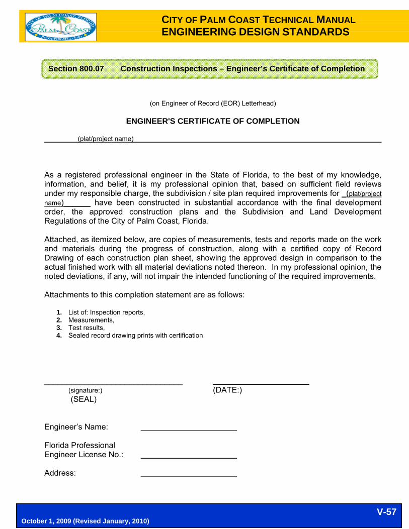
CITY OF PALM COAST TECHNICAL MANUAL ENGINEERING DESIGN STANDARDS
V-57 October 1, 2009 (Revised January, 2010)
(on Engineer of Record (EOR) Letterhead)
ENGINEER'S CERTIFICATE OF COMPLETION
(plat/project name) As a registered professional engineer in the State of Florida, to the best of my knowledge, information, and belief, it is my professional opinion that, based on sufficient field reviews under my responsible charge, the subdivision / site plan required improvements for _(plat/project name)______ have been constructed in substantial accordance with the final development order, the approved construction plans and the Subdivision and Land Development Regulations of the City of Palm Coast, Florida. Attached, as itemized below, are copies of measurements, tests and reports made on the work and materials during the progress of construction, along with a certified copy of Record Drawing of each construction plan sheet, showing the approved design in comparison to the actual finished work with all material deviations noted thereon. In my professional opinion, the noted deviations, if any, will not impair the intended functioning of the required improvements. Attachments to this completion statement are as follows:
1. List of: Inspection reports, 2. Measurements, 3. Test results, 4. Sealed record drawing prints with certification
_______________________________ (signature:) (DATE:) (SEAL) Engineer’s Name: Florida Professional Engineer License No.: Address:
Section 800.07 Construction Inspections – Engineer’s Certificate of Completion

CITY OF PALM COAST TECHNICAL MANUAL ENGINEERING DESIGN STANDARDS
V-58 October 1, 2009 (Revised January, 2010)
A. In order to verify that new development projects within the City are constructed in substantial
accordance with the approved drawings, Record Drawings shall be submitted to the Engineering and Stormwater Department. Record Drawings shall show the following information: 1. “RECORD DRAWING” on each sheet near title block, in minimum ½" font size. 2. A drawing “Legend” for as built information. 3. As built information shall be from measurements provided by a professional land surveyor 4. Name and contact information of the surveyor, and the date(s) of the field measurements 5. Vertical measurements shall be of the same datum reference as the permitted plans, and
shall be stated in the as built measurement certification. 6. Pavement and curb widths for each street 7. High and low points and any intermediate grade changes for all streets 8. As-built centerline profile elevations (to be shown all plan sheets and all plan and profile
sheets). 9. Storm drainage structures shall be located and/or dimensioned from baselines (road
centerlines preferred) by station / offset / elevations... 10. Storm drainage pipe invert and inlet grate as built elevations 11. Storm drainage pipe material, length, and size shall be measured and verified. This
information to clearly indicate it as being as-built information. 12. As built information for all storage and conveyance drainage facilities, such as ditches,
canals. Ponds, lakes, and dry retention and detention (Elevations every 100 feet along the top of bank and toe of slope).
13. Both proposed and as built top of bank areas and volumes for each wet and/or dry retention and detention facility.
14. Storm drainage swale centerlines shall be located and invert elevation of the flow line shall be recorded every 100 feet.
15. Any special features such as, concrete flumes, lake banks, walls, fencing, gate, which were a part of the approved construction drawings should also be shown and dimensioned.
16. Pavement Markings and Signage – horizontal locations B. Notes:
1. Record Drawings shall be prepared using copies of the appropriate sheets of the City approved set of site development plans.
2. Record Drawings shall be submitted electronically in “.pdf” format (300 dpi, 24x36 print size), with all appropriate certifications. One paper copy, signed and sealed shall also be submitted.
3. As-built elevations and distances shall be shown, with the original design information lined out as appropriate.
4. All as-built information shall be based on measurements provided by a professional land Surveyor, licensed by the State of Florida.
5. Record Drawings shall be reviewed and certified by a professional engineer, licensed by the State of Florida.
Section 800.08 Standard Requirements for Paving & Drainage Record Drawings (As-Builts)

CITY OF PALM COAST TECHNICAL MANUAL ENGINEERING DESIGN STANDARDS
V-59 October 1, 2009 (Revised January, 2010)
Return to:
City of Palm Coast Engineering & Stormwater Dept. 160 Cypress Point Pkwy, Ste B106 Palm Coast, FL 32164
BILL OF SALE KNOW ALL MEN BY THESE PRESENTS: That (Developer Name) , a (Corporation, Governing Body, etc.) organized and existing under and by virtue of the laws of the State of Florida, having its principal place of business in the City of (City) , and County of (County) in the State of Florida, party of the first part, for and in consideration of the sum of (See Note 1) Dollars ($ ), in lawful money (and other good and valuable considerations unto it moving) to it paid by the CITY OF PALM COAST, of the City of Palm Coast, County of Flagler, and State of Florida, party of the second part, the sufficiency and receipt of which is hereby acknowledged by it, has granted, bargained, sold, transferred, set over and delivered, and by these presents does grant, bargain, sell, transfer, set over and deliver unto the party of the second part, (Description of the facilities to be Dedicated) and assigns all those certain goods and chattels, described as follows: Project Name County System Connecting To: LIST OF MATERIALS (See Note 2) Item Description Quantity Unit Unit Prices Extended Price 1) 2) TO HAVE AND TO HOLD the same unto the party of the second part, the CITY OF PALM COAST and assigns forever. And the party of the first part, for itself and its successors, hereby covenants to and with the party of the second part, the CITY OF PALM COAST, and assigns that it is the lawful owner of the said goods and chattels; that they are free from all liens and encumbrances; that it has good right to sell the same as aforesaid, and that it will warrant and defend the same against the lawful claims and demands of all persons whomsoever. IN WITNESS WHEREOF, the party of the first part has caused its corporate name to be hereunto subscribed and its corporate seal to be affixed by its officer, hereunto duly authorized, this day of , 20 . By:
(Signature) Typed Name: Typed Title: Signed, sealed and delivered in the presence of: Witnesses: (Signature) (Signature) Name typed: Name typed: State of Florida ) County of ________________ ) The foregoing instrument was acknowledged before me this ________ day of ________ 20 ____ by _______________ who is personally known to me or has produced (Type of identification), as identification and who did/did not take an oath.
Name typed: Notary Public My Commission expires: Note 1: $10.00 typical dollar amount. Note 2: If item is too lengthy, create an Exhibit “A”. Put name of project, date, etc. on Exhibit “A” for reference.
Section 800.09 Bill of Sale

CITY OF PALM COAST TECHNICAL MANUAL ENGINEERING DESIGN STANDARDS
V-60 October 1, 2009 (Revised January, 2010)
A. Application
1. Engineering Department Receives Application and Attachments from applicant; 2. Development Review Technician reviews application and attachments; 3. Development Review Technician recommends approval or request additional information
from applicant; 4. Forward to City Engineer or designee for signature; 5. City Engineer or designee returns to Development Review Technician for approval stamps; 6. Engineering Staff Assistant makes inspection sheet and folder for inspection; 7. Engineering Staff Assistant distributes the application to necessary parties; 8. Engineering Staff Assistant enters the application information into Database Spreadsheet.
B. Preconstruction Inspection of Existing Road Conditions
1. Results are reported to Development Review Technician (via inspection results sheet) 2. Inspection automatically scheduled four (4) weeks after permit issuance if not requested by
permittee. C. Request for Swale Plan (As Appropriate)
1. If swale plan has not been generated, a “Request for Swale Plan” sheet if filled out by the applicant and given to the ESWD.
D. Driveway Inspection Requested (As Appropriate)
1. Inspection requested by Applicant 2. Paperwork prepared for inspector 3. Inspection results are reported to Development Review Technician the following morning
(via inspection results Sheet). E. Receive Final As-built Survey (As Appropriate)
1. Surveys are delivered by Permittee to ESWD staff 2. Surveys delivered to inspector for review. 3. Approved surveys are prepared for inspection. 4. If approved, results are inserted into Database Spreadsheet
A. When applicable, the provisions of the latest editions of the following references shall apply:
1. City of Palm Coast Code of Ordinances. 2. F.S. § 337.401 (and its successors) entitled "Use of Right-of-Way for Utilities Subject to
Regulation". 3. F.S. Ch. 556, entitled "Underground Facility Damage Prevention and Safety Act".
SECTION 900 RIGHT-OF-WAY (R/W) UTILIZATION PERMITS
Section 900.01 Right-of-Way Utilization Permit Procedures
Section 900.02 References

CITY OF PALM COAST TECHNICAL MANUAL ENGINEERING DESIGN STANDARDS
V-61 October 1, 2009 (Revised January, 2010)
4. Florida Department of Transportation Standard Specifications for Road and Bridge Construction. (Most recent edition)
5. Manual on Traffic Controls and Safe Practices for Street and Highway Construction, Maintenance and Utility Operations, Florida Department of Transportation.
6. State of Florida Department of Transportation Utility Accommodation Guide. 7. Manual on Uniform Traffic Control Devices for Streets and Highways (MUTCD). 8. Manual of Uniform Minimum Standards for Design, Construction and Maintenance for
Streets and Highways (Green Book), as published by the Florida Department of Transportation.
9. Florida Department of Transportation Design Standards (Standard Index) (Most recent edition)
B. In the event of a conflict between the provisions of the regulations and specifications referred to
in (a) above, and these technical specifications regarding right-of-way utilization, that which is more restrictive shall apply.
A. The primary concern in the design and location of utility installations is protection of the right-of-
way and the safety of the highway user. In all cases, full consideration shall be given to sound engineering principles.
B. Where possible, all longitudinal underground utility facilities should be placed in an area within
seven (7') feet inside the outer edge of the right-of-way line except where potable water and sanitary sewer lie along the same side of the road, requiring a separation of ten (10') feet between those utility lines. These, and other similar situations, will be considered on a case by case basis. Above ground facilities should be placed at or close as practical to the right-of-way line. Under no condition shall a utility installation interfere with the roadway storm drain system.
C. Proposed location of poles, fire hydrants, water meters, telephone and cable boxes, etc., should
take into consideration future road widening, sidewalk, storm drainage or other construction. Minimum guidelines for roadside recovery area are shown in the State of Florida Department of Transportation Manual of Uniform Minimum Standards for Design, Construction and Maintenance for Streets and Highways. Any deviation from those requirements requires prior approval by the City.
D. Water meter boxes & telephone boxes shall be installed flush with or below the ground. If
installation must protrude to the extent such boxes may be a hindrance to drainage maintenance or mowing, they must be located within two (2') feet of the right-of-way line whether their parallel line runs along the right-of-way line or not: Water meter boxes, telephone boxes or television cable boxes shall not be placed within the limits of a proposed or existing sidewalk, curb, gutter or bike path.
E. No person shall place or maintain upon any City of Palm Coast roadway any sign or signal
bearing thereon any commercial advertising.
Section 900.03 Location Standards (Utility Installations)

CITY OF PALM COAST TECHNICAL MANUAL ENGINEERING DESIGN STANDARDS
V-62 October 1, 2009 (Revised January, 2010)
A. Residential Driveways - Residential driveways entering upon a paved City street shall be
constructed of portland cement concrete, or of such other rigid paving material as the City Engineer may approve, shall be a minimum of ten feet [10') wide at the right-of-way line and sixteen feet (16') wide at the roadway edge. That widening may be provided by a taper. Driveway shoulder within the road right-of-way shall be a minimum of two feet (2') in width and shall be stabilized and sodded. Driveway thickness on the right-of-way shall be either six inches (6") on firmly compacted subgrade of clean granular material or five inches (5") on three inches (3") of limerock or shell base. This concrete thickness may be reduced by one inch (1") by the addition of 6"x 6" re-mesh or fiber mesh concrete reinforcing wire. Culvert pipe shall be of the size and set in the location (horizontal and vertical) established by the City and required by the permit. Mitered or tapered end sections are required on driveway pipes, except where otherwise approved by the City Engineer. Culvert pipes with less than twelve inches (12") of cover below the bottom of driveway pavement to the top of pipe shall either be constructed of reinforced concrete or encased in concrete from the middle of the pipe to the bottom of the concrete driveway. For driveways entering upon a cul-de-sac and for driveways entering a flag lot the minimum width at the roadway edge and the placement of the culvert pipe will be modified to best suit the actual conditions at the site. Existing residential driveways, cut or destroyed by utility installation may be re-constructed to the same section as that original driveway with prior approval from the City. All residential driveways are required to be permitted, in accordance with the above criteria.
B. Commercial Driveways - Commercial driveway requirements shall be dependent on the nature
of the business being served by the driveway. At a minimum; however, commercial driveways shall be constructed of portland cement concrete six inches (6") thick on six inch (6") thick compacted limerock or shell base or eight inches (8") thick on four inches (4") of limerock or shell base. Commercial driveway width depends on the type traffic scheduled to utilize the driveway. At a minimumr the width at the right-of-way line for a one-way driveway shall be fourteen feet (14') and for a two-way driveway shall be twenty four feet (24'). Minimum width at the roadway pavement edge shall be not less than forty-eight feet (48') for one-way commercial driveways and not less than sixty-four feet (64') for a two-way commercial driveway. 1. The widening shall be provided by a taper not less than twenty feet (20') long as measured
along the centerline of the driveway. Shoulders for commercial driveways shall be six feet (6') in width, stabilized and sodded. In addition, turn lanes or acceleration and deceleration lanes may be required, dependent on the road involved and the traffic on that road.
2. Culvert pipes for commercial driveways shall be reinforced concrete pipe culverts, with mitered end sections. Culverts shall be sized and locatedr horizontally and vertically, as specified by the City and shown on the permit. Commercial driveways damaged by utility installations shall be re-constructed to the section described herein.
C. Portland Cement Concrete Material
1. Residential drives shall be constructed using material with a minimum twenty-eight (28) day compressive strength of three thousand pounds (3,000 Ibs.) per square inch.
2. Commercial drives shall be constructed using Florida Department of Transportation Class 1 material with a minimum twenty-eight (28) day compressive strength of three thousand pounds (3,000 lbs.) per square inch placed with a maximum slump of five (5) inches.
Section 900.04 Driveways

CITY OF PALM COAST TECHNICAL MANUAL ENGINEERING DESIGN STANDARDS
V-63 October 1, 2009 (Revised January, 2010)
D. Temporary Driveways - Temporary access for residential or commercial units from City roads
will be permitted under the following conditions: 1. Responsible party submits application for a permit. 2. City representatives will visit the site and determine the size, type, and length of culvert
pipe needed to provide proper drainage (if any). 3. Permit will state size, type, length and elevations for culvert installation, as well as width of
access point at the roadway and at the right-of-way line, and any other conditions. 4. For entrances, with sufficient cover over the culvert to protect the drainage structure, where
heavy equipment is expected to use the entrance on an intermittent basis, no surface material will normally be required. For entrances expected to carry a high concentration of heavy vehicles, the surface shall be stabilized with limerock or shell.
5. For driveways, installed to provide temporary access prior to constructing on the property, the surface shall be stabilized sufficiently to permit passage of vehicular traffic without rutting.
6. All culvert pipes shall be back filled with select granular material, compacted to a tight homogeneous mass. The permittee shall be responsible for maintaining the access in a passable condition. The City will not re-grade or surface temporary entrances.
7. Permits for temporary driveways are valid for one (1) year from date of issue and a permanent access permit must be obtained prior to that time. Such permits may be extended for another one (1) year period, provided the Permittee demonstrates an acceptable reason for the delay in obtaining a permanent permit. A right of way utilization permit for permanent access shall be required for any access from a city street to residential or commercial building.
8. The fee for temporary driveways shall be the same as for a permanent driveway; however no additional fee will be charged to replace a temporary driveway with a permanent access to the same parcel or tract of land, provided the permitted temporary driveway is removed, or becomes the permanent access. Permanent driveways shall meet the requirements listed hereinafter. The City will not participate in the installation of any access from/to City road(s) for any type access.
A. A single application form furnished by the Permitting Office shall be used when applying for a
Right-of-Way Utilization Permit. Applications forms may be obtained at the City of Palm Coast's Engineering and Stormwater Department. Completed applications shall be submitted to that office.
B. Information provided by the applicant in completing the application form shall be typewritten or
printed in ink. The application must be legible and all requested information must be provided. Incomplete applications will not be accepted.
C. Three (3) sets of a sketch or plan, not necessarily to scale, shall accompany the application and
shall reflect both a plan and cross-section view of the proposed work. This shall be drawing that can be folded to a size not to exceed 8 l/2" x 11". It shall show the OFF-SET FROM THE CENTERLINE of the right-of-way or roads to the proposed work, the road right-of-way width and pavement width, the distance from edge of pavement to the utility, sidewalk/bikeway, driveway pipe, etc. and the location of all utilities within the area of work. One or more typical cross-
Section 900.05 Permit Application

CITY OF PALM COAST TECHNICAL MANUAL ENGINEERING DESIGN STANDARDS
V-64 October 1, 2009 (Revised January, 2010)
sections, as required to adequately reflect the vertical location of the work, shall be shown. The minimum vertical clearance above or below the pavement shall be shown. Additional information such as the location in relation to the nearest road intersection, bridges, railroad crossings and other physical features shall be indicated on the drawing and identified. A simple key map showing the location of the proposed facility shall be included either on the sketch or plan itself, or as a separate sketch or plan, showing the general location of the installation, and indicating the applicable section, block, and lot, street address, or other information necessary to identity the site.
D. Upon approval of the application and payment of the fee, one copy of the approved application
(permit) with attachments will be returned to the applicant. A. General considerations: The normal crossing under paved surfaces will be made without
cutting the pavement. Pavement cuts will be considered only under unusual conditions and permission must be requested in writing. 1. Casings will be required for crossing of underground utilities under existing pavement,
where the carrier conduit is of insufficient strength due to composition or depth of cover. No jetting (air, water, etc.) is authorized within any rights-of-way in the City of Palm Coast.
2. All subterranean crossings of a traveled way, thirty (30') feet or more in width, shall require a track type bore and jack, with encased auger. Crossings of traveled ways less than thirty (30') feet wide may be made by boring, jacking, pushing, pulling, driving, or some combination of these, having a positive horizontal and vertical control. Pits required for these crossings must be constructed no closer than six (6') feet from the edge of the traveled way.
3. Closed end jacking may be permitted for pipes with a maximum outside diameter of three (3") inches. The pipe shall extend a minimum of six (6') feet beyond the edge of the pavement, except where connections to another utility, closer than the specified six feet (6'), are necessary.
4. All other pipe must be jacked with the end open or bore and jacked and extend a minimum of six (6') feet beyond the edge of pavement or as otherwise approved by the City. If mechanical boring is used, the tip of the drill head shall not precede the end of the jacked pipe by more than two (2") inches.
5. All such crossing shall be continuous operation and shall be completed and the pits backfilled and properly compacted and the site cleaned up and sodded prior to ceasing the operation.
6. Directional Boring, or methods other than those described above may be permitted, provided the Applicant can demonstrate expertise in the proposed method to the satisfaction of the City Engineer.
B. Open street cuts.
1. Traffic through the construction area shall be maintained in accordance with the requirements shown on the Permit.
2. Restoration of the right-of-way will be in accordance with the Permit requirements.
C. Canals, ditches and swales. 1. The minimum depth of cover for crossings under facilities identified as part of the City's
Primary Drainage System, and City's Secondary Drainage Facilities, which are of
Section 900.06 Utility or Stormwater Crossings

CITY OF PALM COAST TECHNICAL MANUAL ENGINEERING DESIGN STANDARDS
V-65 October 1, 2009 (Revised January, 2010)
comparable size to the Primary Facilities, shall be eighteen inches (18") from the top of the utility installation to the design or existing (whichever is the lowest elevation) canal or ditch bottom. The minimum depth of cover for crossings under all other canals and ditches shall be twenty-four inches (24") from the top of the utility installation to the design, or existing, ditch bottom whichever is lowest.
2. The minimum vertical distance for crossings over any waterway shall be twenty-four inches (24") from the bottom of the utility to the 100 Year Flood Elevation, except those ditches or waterways where small boat traffic can be expected, where the minimum clear vertical clearance shall be forty-eight inches (48"). No overhead crossings of navigable canals will be permitted. The minimum vertical clearance shall be implemented for the full length of the crossing from the top-of-bank to top-of-bank. The crossing shall not increase to the existing 100 Year Flood Elevation. A child proof barrier shall be required for crossings over waterways. The crossing shall not impede maintenance equipment or maintenance operations of the waterway.
3. Drainage swales shall be restored to a design grade and any damage to swale area shall be fully repaired, including sodding, to conform to such condition as the swale existed prior to construction or to such other shape and grade as may be approved by the City Engineer.
D. Faulty workmanship or materials.
1. Faulty workmanship shall be repaired within thirty (30) days of notification from the City to like or better condition than existing prior to construction unless a longer period is approved by the City Engineer.
2. Any repairs or replacement not completed within the thirty (30) day time limit may result in refusal to issue further right-of-way permits to the applicant concerned. The City reserves the right to repair such damages, after the thirty (30) day time limit, with its own forces and charge the Contractor and/or Owner for One Hundred Fifty percent (150%) of the cost of such repairs.
A. Compliance. All construction shall be in accordance with current LDC and Technical Manual
standards and Florida Department of Transportation design standards. In the event of a conflict between standards, the City standards shall apply.
B. Buried utility lines. Minimum vertical clearance for direct buried cable, conduit casings, utility
lines, and duct systems shall be per location criteria for utilities in the State of Florida Department of Transportation Utility Accommodation Manual or in accordance with the requirements of Palm Coast's Cable TV regulatory ordinance where that ordinance applies. Coaxial and glass fiber cables shall be buried a minimum of twenty-four inches (24") below the existing ground.
C. Storm drainage structures. Installation shall be in accordance with current LDC and
Technical Manual standards and Florida Department of Transportation design standards. In the event of a conflict between standards, the City standards shall apply.
Section 900.07 Construction Standards

CITY OF PALM COAST TECHNICAL MANUAL ENGINEERING DESIGN STANDARDS
V-66 October 1, 2009 (Revised January, 2010)
D. Backfill and compaction. Backfill with clean granule material and testing requirements shall be in accordance with City requirements. Backfill shall be in accordance with the State of Florida Department of Transportation Utility Accommodation Manual unless otherwise stated in permit requirements. If requested by the Applicant, special back filling materials and/or methods will be considered.
E. Traffic signals. Utilities or contractors working at intersections where traffic signals are
responsible for the location of underground signal conduit, wiring and/or fiber. Damages incurred will be the responsibility of the permittee. Repairs may be made by contract personnel, but must be made with the concurrence and under the requirements as set forth by the City Engineer. In some instances, repairs may be made by City, with total costs billed to the permittee. The permittee shall be fully responsible for damage or loss of any traffic sign or control device caused by any commission or omission, neglect, or misconduct in the performance of the work by and/or for the permittee.
F. Traffic signs. When traffic signs are located within the area of approved installation or
construction, the permittee is required to notify the City of Palm Coast to arrange for removal and/or relocation. Costs incurred by the City for the removal and resetting, or relocations of signs will be billed to the permittee. The Permittee shall be fully responsible for the replacement or cost of any traffic sign or device removed or damaged due to its operation. Relocation/re-setting shall comply with MUTCD.
G. Pavement markings.
1. Utility companies or contractors having permitted installation or construction within paved sections of roadway that disturb or destroy current pavement markings shall be required to replace said pavement markings with approved thermoplastic marking material and to restore such markings to their original condition.
2. When new turn, bypass, deceleration and/or acceleration lanes are constructed in accordance with approved plans, a striping plan shall be submitted for the approval of the City Engineer. Striping shall be accomplished by the permittee in accordance with the approved plans.
H. Prohibitions. Tunneling or jetting within public right-of-way is prohibited.
A. Density tests conducted in accordance with applicable F.D.O.T. specs for determination of the
specified backfill, base, and other compaction shall be made be an independent testing laboratory, licensed in the State of Florida and approved by the City, or by a certified technician utilizing a method approved by the City Engineer at the expense of the permittee and copies of all reports from those technicians or testing laboratory shall be submitted to the City Engineer.
B. If any test results are unsatisfactory, the permittee shall re-excavate and recompact the backfill
at its expense until the desired compaction is obtained. Additional compaction tests shall be made to each side of an unsatisfactory test, as directed by the City, to determine the extent of re-excavation and recompaction necessary.
C. Concrete compressive strength tests are required and copies of the results of such tests shall
be submitted to the City Engineer.
Section 900.08 Testing

CITY OF PALM COAST TECHNICAL MANUAL ENGINEERING DESIGN STANDARDS
V-67 October 1, 2009 (Revised January, 2010)
A. The permittee shall notify the City Engineer at least twenty-four (24) hours prior to beginning
work. The date, time and location regarding the work must be given at the time of this notification. The City Engineer shall be immediately notified of any revisions to the schedule.
B. Underground facilities (buried cable, water lines, drainage structures, etc.) will not be covered
until inspected and approved by the City Engineer or his Designee except in instances where the permittee has sufficient density tests to confirm proper compaction has been obtained and leaving the facility uncovered would create an unsafe or unsound condition. Cable facilities need not be left exposed when buried by the direct burial process provided the contractor has demonstrated his competence in such construction. The City reserves the right to require exposure of all or portions of the installation to verify correct depth of cover.
C. Failure of the permittee to obtain the appropriate inspections prior to proceeding with work shall
not relieve the permittee from re-excavation or other measures necessary for the inspection of the work and cost of such re-excavation shall be the permittee's sole expense.
D. Any items not in compliance with these requirements will be immediately corrected by the
permittee.
E. The inspector's signature on the completion line on the permit terminates that permit and no further work may be done under that permit except such repairs or area clean up as are directed by the City Engineer.
F. Reinspections. Permittee shall be charged an additional fee for each re-inspection required
should permittee call for an inspection and NOT be prepared or have said work ready for requested inspection. Re-inspection fees shall be established by resolution of the Palm Coast City Council.
Operations permitted by this regulation which require inspection by City Forces shall normally be conducted from 8:00 a.m. to 5:00 p.m. Monday through Friday, excluding holidays. Any deviation from those hours requires prior approval from the City, and any overtime payments for inspection will be billed at current manpower expense rates. Those charges will be paid by the permittee, in accordance with current City billing requirements. A minimum of two (2) working days notice, in writing, requesting deviation from normal working hours, must be provided. Such written notice is not required if the work times have been included as a part of the permit. Emergency repairs are excluded from this time restriction.
Section 900.09 Inspection
Section 900.10 Working Hours

CITY OF PALM COAST TECHNICAL MANUAL ENGINEERING DESIGN STANDARDS
V-68 October 1, 2009 (Revised January, 2010)
Except for residential driveways and emergency repairs, if the work involves construction on or near a traveled way, the permittee shall provide the City Engineer with its proposed Maintenance of Traffic plan at least five (5) working days prior to commencement of any work on the project and-shall not commence work until the plan has been approved by the City Engineer. Notification to affected emergency agencies (Fire, Rescue, Police, etc.) shall be the responsibility of the City Engineer; however the permittee may be required to notify the news media in some instances, including the possibility of paid advertisements, and to bear the costs of such notifications. Unless otherwise provided, all roads within the limits of the permit shall be kept open to traffic. When approved by the City, traffic may be bypassed over an approved detour route. The permittee shall keep the portion of the project being used by the public, whether it is through or local traffic, in such condition that traffic will be adequately accommodated. He shall furnish, erect and maintain barricades, warning signs, delineators, flagmen or pilot cars in accordance with the Manual on Uniform Traffic Control Devices. He shall also provide and maintain temporary approaches or crossings, and intersections with trails, roads, streets, businesses, parking lots, residences, garages, and farms in a safe condition. The permittee shall bear all expenses of maintaining the traffic over the section of road undergoing construction and of maintaining such approaches, crossings, intersections, detours, and other features as may be necessary. Materials stored at the site of the work shall be so placed as to cause no obstruction to vehicular or pedestrian traffic. Any equipment or materials stored within the right-of-way shall be properly barricaded. No roadway shall be closed or re-opened except by express permission of the City Engineer. When an open cut of a road has been authorized, and a detour/diversion traffic route has not been requested or approved by the City no lane closure will be authorized prior to 8:00 a.m. or later than 3:00 p.m. without specific and individual approval. In the case of a 2-way/2-lane road one lane traffic may be authorized during this period. In the case of a 2-way/4-lane road, 2-way/2-lane traffic will normally be required. A. General requirements
1. Installation of any landscaping and irrigation systems, and/or related materials within dedicated or planned public rights-of-way is prohibited without the express approval of the City. This approval shall be based on issuance of a Right-of-Way Utilization Permit authorizing such installation or construction. Maintenance of any of the aforementioned project will be the responsibility of the signatories.
2. Persons and equipment maintaining any authorized landscaping or irrigation systems, must perform such maintenance work in a manner so as not to create safety hazards or obstruct vision or normal traffic flow. Spray patterns shall not cross pedestrian walk ways nor shall any irrigation water be allowed to fall on a travelway, except as hereinafter provided.
3. If, in the opinion of the City, damages in or adjacent to the right-of-way are deemed to have been caused by construction, then maintenance or restoration of a landscaping or irrigation system will be the responsibility of the Right-of-Way Utilization permittee.
Section 900.11 Maintenance of Traffic
Section 900.12 Landscaping and Irrigation Systems

CITY OF PALM COAST TECHNICAL MANUAL ENGINEERING DESIGN STANDARDS
V-69 October 1, 2009 (Revised January, 2010)
B. Landscaping 1. No landscaping or improvement to existing landscaping shall be planted or constructed
within the right-of-way unless such landscape construction plans have been approved by the City Engineer and a valid Right-of-Way Utilization Permit has been authorized and issued by the City.
2. Landscaping in a median island and within one hundred (100') feet of a median nose shall be installed and maintained at a maximum height of twenty-four (24") inches above road grade at the center line of travelway. Normally trees will not be allowed to be installed in medians, unless clear zone and clear sight distance zone requirements will allow installation without violation of those clear zone requirements.
3. A four (4') foot minimum mowing strip shall be maintained between plantings and the curb or pavement edge.
4. No rocks, boulders, railroad cross ties, heavy timbers or other obstructions, shall be used within the right-of-way without special and specific written permission.
5. On divided or undivided highways or roads, trees will not be allowed to be planted or to remain in the clear recovery zone. The required minimum width of the clear recovery zone adjacent to the traveled way is shown in the Manual of Uniform Minimum Standards for Design Construction and Maintenance for Streets and Highways (Green Book) as published by the Florida Department of Transportation. Trees and other plants on private property shall not be allowed to overhang the right-of-way to the extent they screen traffic sight distances at intersections.
6. Poisonous or exotic pest plant species shall not be planted in any planned or dedicated public rights-of-way.
7. Landscaping planned for either a parkway or median strip will not be authorized if, in the opinion of the City, such installation would possibly create a safety hazard or sight obstruction. Safety of the public will be a predominant factor in all decisions. The applicant shall demonstrate at the time of the permitting that the sight distance will not be impaired to the motoring public in any direction by landscaping and plantings now or in the future. The Manual on Uniform Traffic Control Devices and the Florida Manual on Uniform Minimum Standards for Design, Construction and Maintenance for Streets and Highways shall be used as a reference.
C. Irrigation Systems
1. No irrigation systems or appurtenances thereto, shall be placed within the right-of-way, unless irrigation construction plans have been approved by the City and a valid Right-of-Way Utilization Permit, applied for by a County or State licensed contractor, has been authorized by the City.
2. Sprinkler heads within the safe recovery area must be of the pop-up type (no stand-ups authorized). Feeder hoses with drip lines may be used. The sprinkler system must be installed in such a manner so that it will not create a traffic or safety hazard.
3. Underground systems and crossings will be made in accordance with the Utility requirements of this regulation, and any deviation from that regulation will result in issuance of a violation notice and revocation of the permit.
4. Minimum cover, other than beneath the traveled way or within six feet (6') of the traveled way, for irrigations systems shall be twelve (12") inches, if piping is used, and six (6") inches, if a feeder hose with drip line is used.
5. No jetting (air; water etc.) is authorized within any public rights-of-way. 6. Pumps, wells, electrical control devices, and other associated items, relating to irrigation
systems, unless specifically approved by the City, will not be permitted in the public rights-of-way.
7. Irrigation systems shall not be allowed to be constructed, either in the public right-of-way, or on private property, that are designed or constructed in such a manner that water flows from

CITY OF PALM COAST TECHNICAL MANUAL ENGINEERING DESIGN STANDARDS
V-70 October 1, 2009 (Revised January, 2010)
sprinkler heads over roads, sidewalks and/or bike paths that have been constructed for and used by the public, unless the Permit allows, and the permittee specifically agrees, that the irrigation system will not be operated during the hours that pedestrians and cyclists are apt to be passing. Unauthorized irrigation systems such as herein described will be subject to legal action and penalty as prescribed by law and/or revocation of the "Right-of-Way Utilization Permit".
A. Application
1. The Applicant - is a person’s name 2. The Firm Name - is the Company performing the work
B. Four (4) copies of Site Plan C. Detailed Description of work
D. Public Notice Advertisement (sample provided at contractors request)
E. Location map (maps are provided for this use at contractors request)
F. Maintenance of traffic plan (site specific)
G. If you are a Contractor working for City, Developer, Owner – state this on the application. THIS SPACE INTENTIONALLY LEFT BLANK
Section 900.13 Right-of-Way Permit Application Information Sheet

CITY OF PALM COAST TECHNICAL MANUAL ENGINEERING DESIGN STANDARDS
V-71 October 1, 2009 (Revised January, 2010)
Section 900.14 Sample Right-of-Way Utilization Permit (Commercial)

CITY OF PALM COAST TECHNICAL MANUAL ENGINEERING DESIGN STANDARDS
V-72 October 1, 2009 (Revised January, 2010)

CITY OF PALM COAST TECHNICAL MANUAL ENGINEERING DESIGN STANDARDS
V-73 October 1, 2009 (Revised January, 2010)
A. Signs at signalized intersections shall be LED internally illuminated. B. Letter Type: Series “E Modified 2000" UPPER Case letters shall be used.
1. The font may be thinned to a C (with prior approval from City of Palm Coast Engineering). Fonts A and B are NOT allowed.
2. The primary lettering/legend height shall be 8 inches for all LED internally illuminated street name signs at all signalized intersections.
3. Supplementary text to indicate the type of street (such as Parkway, Drive or Road, appropriately abbreviated) or the section of the City (such as NW) shall be 3 inch high UPPER Case letters centered below the street name.
C. Sign Dimensions (Horizontal and Vertical):
1. The sign size is determined primarily by the length of the message, the size of the lettering and spacing necessary for proper legibility.
2. Reduced spacing between the letters or words on a line of legend should not be used as a means of reducing the overall size of the guide sign, except where determined necessary by engineering judgment, and approved by the City of Palm Coast Engineering, to meet unusual lateral space constraints.
3. The legibility distance of the sign legend should be the primary consideration in determining whether to reduce the spacing between the letters or the words or between the words and the sign border.
D. Street signs at signalized intersections shall be mounted on a separate sign support just below
the signal mast arm. Mounting the street signs between signal heads centered on the travel lanes is not preferred.
E. The following is a SAMPLE sign panel. F. The Contractor shall install and test in place the LED internally illuminated street name signs.
The signs are to be burned in for 60 days before final acceptance. The signs shall be breakered separately from the signal cabinet and shall be controlled by one master photocell.
G. All LED internally illuminated street name signs shall be double faced unless otherwise
approved by City of Palm Coast Engineering Department.
SECTION 1000 TRAFFIC
Section 1000.01 Street Name Signs at Signalized Intersections

CITY OF PALM COAST TECHNICAL MANUAL ENGINEERING DESIGN STANDARDS
V-74 October 1, 2009 (Revised January, 2010)
Section 1000.02 Street Name Signs at Non-Signalized Intersections

CITY OF PALM COAST TECHNICAL MANUAL ENGINEERING DESIGN STANDARDS
V-75 October 1, 2009 (Revised January, 2010)
A. Streets with speed limits of 40 MPH or less
1. Street name lettering on ground-mounted signs shall be 6 inch high capital letters. (Streets with speed limit less than 25 mph may be 4 inch high capital letters.)
2. Supplementary lettering to indicate the type of street (such as Street, Avenue, or Road, appropriately abbreviated) or the section of the City (such as NW) shall be 3 inch high capital letters.
3. Street name signs shall be retroreflective to show the same shape and similar color both day and night and shall have a white legend on a green background and no border.
B. Multi-lane streets with speed limits greater than 40 MPH
1. Street name lettering on ground-mounted signs shall be 8 inch high capital letters. 2. Supplementary lettering to indicate the type of street (such as Street, Avenue, or Road,
appropriately abbreviated) or the section of the City (such as NW) shall be 4 inch high capital letters.
3. Street name signs shall be retro-reflective to show the same shape and similar color both day and night and shall have a white legend on a green background and no border.
A. Delay times shall be set to 5 seconds. B. The City of Palm Coast requires Naztec TS 2 controller assemblies.
C. A manual push button cord shall be furnished in the controller cabinet.
D. All base mounted controller cabinets shall be Type 5 aluminum, back panel wired for SOP 10
and initially set for the SOP shown in the plans.
E. The cabinet door shall open away from the intersection unless specified otherwise.
F. The controller base and service pad shall be a monolithic concrete pour with 4 inches minimum / 8 inches maximum above finished grade.
G. The mounting or attachment of the electrical service to the traffic signal cabinet shall be
prohibited.
H. Emergency preemption shall be included with all signal installations and upgrades and be compatible with the City’s Opticom GPS system. (Section 1000.09)
A. The Contractor shall provide a Drilled Shaft Installation Plan to the City of Palm Coast
Engineering Department prior to construction. The Plan shall include the concrete mix design. B. After completion of the Drilled Shafts the Contractor shall submit the Drilled Shaft Inspection
Reports to the City of Palm Coast Engineering Department.
Section 1000.03 Traffic Signal Controller
Section 1000.04 Mast Arm Construction

CITY OF PALM COAST TECHNICAL MANUAL ENGINEERING DESIGN STANDARDS
V-76 October 1, 2009 (Revised January, 2010)
C. The Contractor shall submit the Anchor Bolt manufacturer certifications to the City of Palm Coast Engineering Department.
A. All arterial and collector streets, as defined below, shall be pavement marked as detailed herein.
These guidelines apply to newly constructed, overlaid or existing pavement. B. Arterials.
1. Arterials NOT scheduled for repaving within the next three years shall receive thermoplastic pavement markings.
2. Arterials scheduled for repaving within three years shall receive painted pavement markings. C. Collectors
1. Collectors NOT scheduled for repaving within the next three years shall receive thermoplastic pavement markings.
2. Collectors scheduled for repaving within the next three years shall receive painted pavement markings.
3. Collectors with abutting residential driveways shall not receive an edge line. D. All roads which intersect a roadway with a speed limit of 40 mph or greater, regardless of
classification, shall receive a stop bar with 40 LF of double yellow centerline measured from the stop bar.
E. All Pavement Markings, including Reflective Pavement Markers, shall be in accordance with the most recent FDOT Design Standards and MUTCD.
F. Pavement markings shall be evaluated annually for functionality. Pavement markings shall be evaluated for daytime visibility and nighttime reflectivity. Pavement markings failing functionality shall be scheduled for replacement as soon as practical.
G. Street classifications are defined by Section 334.03, Florida Statues and are listed below: 1. "Arterial street" means a route providing service which is relatively continuous and of
relatively high traffic volume, long average trip length, high operating speed, and high mobility importance. i.e., – Palm Coast Parkway, Belle Terre Parkway, etc.
2. "Collector street" means a route providing service which is of relatively moderate average traffic volume, moderately average trip length, and moderately average operating speed. Such a route also collects and distributes traffic between local streets or arterial streets and serves as a linkage between land access and mobility needs. i.e. – Florida Park Drive, White View Parkway, etc.
3. "Local street" means a route providing service which is of relatively low average traffic volume, short average trip length or minimal through-traffic movements, and high land access for abutting property.
A. The intent of typical signing arrangement at one-way intersections is to reduce confusion by
eliminating unwarranted signage, increase driver comprehension by placing signs in a more visible location, increase awareness by standardizing sign placement within one-way intersections.
B. When making modifications to an existing intersection or constructing a new intersection in
which one or both of the streets have one way characteristics, the following guidance shall be used to sign the intersection:
Section 1000.05 Pavement Markings
Section 1000.06 One-Way Street Intersection Signage

CITY OF PALM COAST TECHNICAL MANUAL ENGINEERING DESIGN STANDARDS
V-77 October 1, 2009 (Revised January, 2010)
C. DO NOT ENTER (R5-1) signs shall be used on either side of the stop bar angled slightly in
towards the intersection. D. ONE-WAY (R6-2) sign shall be mounted between the signal heads on the span wire or mast
arm. E. Symbolic Turn Prohibition signs (R3-1 or R3-2) shall be mounted between the signal heads on
the span wire or mast arm. All new installations of these signs shall be LED to ensure nighttime visibility.
F. The following figure shows a sample of sign locations: A. Upon project acceptance, the City of Palm Coast will accept maintenance and energy costs for
only standard FPL installed residential street lights with-in public road right-of-way, to include those that meet the following criteria: 1. Lights at intersections along roadways classified as residential collectors, or arterials. 2. Lights that provide illumination for designated pedestrian crossings. 3. Lights that illuminate school bus stops. 4. Lights that illuminate what would be deemed potentially hazardous roadways. These
locations will be evaluated on a case by case basis, and at the sole discretion of the City of Palm Coast.
Section 1000.07 Street Lights

CITY OF PALM COAST TECHNICAL MANUAL ENGINEERING DESIGN STANDARDS
V-78 October 1, 2009 (Revised January, 2010)
5. Lights that meet the outlined criteria and can be billed separately. B. All other lights and additional costs associated with decorative or other types of lighting will be
the responsibility of others. C. The City of Palm Coast will not accept financial responsibility for street lighting installed to
subsection 9.07.06 of the Unified LDC. Street lighting falling within this category will remain the responsibility of others.
D. The above outlined criteria will be reviewed by the City Engineer or his designee for each
request prior to any assumption of cost. A. The Contractor shall obtain a Right of Way Permit from the City of Palm Coast prior to beginning
any signal work. B. The Contractor is required to inspect the installation of the traffic signal in accordance with
FDOT Specification 105-5.10.
C. The Contractor shall coordinate the final acceptance inspection in accordance with FDOT Specification 611-2.2 with the Engineer and the City of Palm Coast at least ten days in advance.
D. At the time of final project inspection the Contractor shall furnish the inspector with three
complete sets of as-built plans to the City of Palm Coast Engineering Department.
E. The mast arm assemblies shall be BLACK in color. The coating shall be in accordance with FDOT Standard Specifications.
F. Backplates shall be used on all signal heads facing east / west directions.
G. The preferred location for the pedestrian activation button is on the mast arm pole. If this
location is not feasible, due to ADA constraints, the buttons may be placed on a separate pole. The separate pole shall match the mast arm pole.
H. Luminaries shall be mounted on each mast arm to provide intersection illumination.
I. Unless otherwise detailed herein, the Contractor shall follow the FDOT Standard Specifications
and Design Standards editions specified on the key sheet of the project plans. A. System Description
1. The required priority control system will employ data-encoded radio communication to identify the presence of designated priority vehicles. A record of system users by agency identification number, vehicle classification and vehicle identification number will be created. In priority vehicle mode, the data-encoded communication will request the traffic signal
Section 1000.08 Traffic General Notes
Section 1000.09 Radio Activated, GPS Based Traffic Signal Priority Control System
CITY OF PALM COAST TECHNICAL MANUAL ENGINEERING DESIGN STANDARDS
V-79 October 1, 2009 (Revised January, 2010)
controller to advance to and / or hold a desired traffic signal display selected from phases normally available.
2. The priority control system will consist of a matched system of vehicle equipment and intersection equipment. The vehicle equipment includes a radio, processor board, and GPS receiver contained in one unit, a GPS antenna and a radio antenna contained in one module, cable, system software, and a vehicle control unit in a separate module. The intersection equipment includes a radio, radio antenna, GPS receiver, and GPS antenna contained in one module, cable, phase selectors and system software.
3. The GPS receiver on the vehicle will obtain vehicle location, heading and speed from the U.S. Department of Defense (DoD) operated satellites. The vehicle equipment will also monitor the vehicle’s turn signal status. A 2.4 GHz spread spectrum/frequency hopping radio in the vehicle equipment will transmit this data to nearby intersections, only when it is within radio communication range of an intersection, which is received by a similar radio located at the intersection. The vehicle radio will communicate to intersection radios at distances up to at least 2,500 feet (762 m) with no obstructions. The intersection radios will communicate to vehicles and other intersection radios at distances of up to at least 2,500 feet (762m) with no obstructions. The phase selector will process the vehicle information to ensure that the vehicle is (1) in a predefined approach corridor, (2) heading toward the intersection, (3) requesting priority, and (4) within user-settable range. If these conditions are met, the phase selector will generate a priority control request to the traffic controller for the approaching priority vehicle. If the approaching vehicle has an active turn signal, the approach intersection will relay the priority request to the next nearest in-range intersection in the direction of the approaching vehicle’s turn signal. The output of the phase selector may also be varied depending on the state of the approaching vehicle’s turn signal.
4. The system will require no action from the vehicle operator other than to turn on the vehicle equipment. A remote activation line will be provided so that activation may happen at the same time as the driver activates other equipment such as a lightbar. The system will operate on a first-come, first-served basis. High priority requests will override Low priority requests. The system will interface with most traffic signal controllers and will not compromise normal operation or existing safety provisions.
B. Matched System Components
1. The required priority control system will be comprised of seven basic matched components: vehicle / intersection radio/GPS module, vehicle control module, vehicle/intersection radio/GPS antenna, intersection only radio/GPS module, radio/GPS cable, phase selector and system software. In addition, a card rack, an interface panel with additional outputs and an auxiliary harness will be available if required. To ensure system integrity, operation and compatibility, all components will be from the same manufacturer. The system will offer compatibility with most signal controllers, e.g. NEMA (National Electrical Manufacturers Association), 170. The system can be interfaced with most globally available controllers using the controller’s preemption inputs. An RS-232 interface shall also be available. a. Vehicle/Intersection radio/GPS module, Radio/GPS Antenna, and vehicle control unit.
The radio/GPS module will obtain the vehicle position, speed and heading information and transmit this information only when within range of a GPS intersection. The vehicle control unit will communicate with the radio/GPS module and provide the interface to the vehicle in order to monitor the vehicle’s turn signal status, provide activation and disable inputs as well as regulate the vehicle power provided to the radio/GPS module.
b. Intersection Radio/GPS Module. The intersection radio/GPS module will transmit a beacon every second and receive the data transmitted by the vehicle equipment and relay this information to the phase selector as well as other system-equipped intersections. It will also obtain position information from the GPS satellites.

CITY OF PALM COAST TECHNICAL MANUAL ENGINEERING DESIGN STANDARDS
V-80 October 1, 2009 (Revised January, 2010)
c. Radio/GPS Cable. The radio/GPS cable will carry the data received from the intersection radio/GPS unit to the phase selector. It will also carry the power for the radio and GPS components provided by the phase selector. The same cable will be used to carry the data between the vehicle radio/GPS unit and the vehicle control unit.
d. Phase Selector. The phase selector will process the data in order to validate that all parameters required for granting a priority request are met. It will be located within the controller cabinet at the intersection. It will request the controller to provide priority to a valid priority vehicle by connecting its outputs to the traffic controller’s preemption inputs.
e. System Software. The system software will operate on any Windows™ operating system currently supported by Microsoft™ and Internet Explorer V5.5 or later compliant program. It supports system configuration and gathering of operational information.
f. Card Rack. The card rack will provide simplified installation of a phase selector into controller cabinets that do not already have a suitable card rack. The card rack will provide the +24 VDC required to operate the phase selector.
g. Auxiliary Interface Panel/Harness. The auxiliary panel will provide additional preemption outputs if needed. It will also provide a connection point for the phase selector to monitor the status of the intersection’s green lights (green sense). Additional communication ports may also be accessed via this panel.
2. If additional outputs are not required, an auxiliary harness will be used to monitor the status of the intersection’s green lights.
C. System Component Specifications
1. Vehicle/Intersection Radio/GPS Module Radio/GPS Antenna and Vehicle Control Unit a. A GPS receiver and antenna will obtain the vehicle position, speed and heading from
the GPS satellite system operated by the DoD. The time information from the GPS satellites will also be used to synchronize the frequency hopping of the 2.4 GHz radio.
b. A 2.4 GHz spread spectrum/frequency hopping radio will provide the communications from the vehicle to the intersection when with in range of a GPS intersection. The radio shall have a transmit power of not more than 1 watt. The radio shall have an unobstructed range of at least 2,500 feet (762 m). The radio will meet FCC Part 15 rules.
c. The Vehicle Control Unit will provide the interface between the vehicle and the priority control system. The vehicle control unit will also interface with the radio/GPS module. The vehicle control unit will monitor the status of the vehicle turn signal via an interface cable that will connect between the vehicle control unit and the left and right turn signal lines in the vehicle. The vehicle control unit will also monitor the disable input line as well as the remote activation input. Power to the vehicle equipment will be provided through the vehicle control unit.
d. The Vehicle Control Unit will have dimensions of no greater than 5.5 inches (14.0cm) wide by 1.75 inches (4.4 cm) high by 5.75 inches (14.6 cm) deep.
e. The radio/GPS module will have dimensions of no greater than 4.5 inches (11.4 cm) wide by 2.75 inches (7.0 cm) high by 8.0 inches (20.3cm) long. This module may also be used in the intersection.
f. The radio/GPS antenna will be a hemispherical dome with a height of 1.43" (3.6 cm) a diameter of 2.85" (7.2 cm) with a pair of 15' (4.6m) cables for the GPS signal and the radio signal. This antenna (along with the radio/GPS module described in subsection 1000.09.C.1.e above) may also be used in the intersection.
g. The radio / GPS module will be housed in extruded aluminum housing. h. The vehicle equipment will be supplied complete with a 20-foot (6.1m) (or longer)
installation cable as well as a 15-foot (4.5m) (or longer) vehicle interface cable.

CITY OF PALM COAST TECHNICAL MANUAL ENGINEERING DESIGN STANDARDS
V-81 October 1, 2009 (Revised January, 2010)
i. The vehicle will transmit the following information when within range of an equipped intersection: (1) The priority level of the vehicle equipment. This will be either high priority or low
priority. The priority level will be factory set. The High priority model will have the option to be wired to operate as low priority either permanently or temporarily.
(2) The agency ID, vehicle classification ID and vehicle ID of the vehicle. Setting these ID numbers will be accomplished through programming software. Each vehicle control unit will be capable of setting 254 different agency IDs and 15 different vehicle type classifications with 9,999 different identification numbers per class for a total of 38,096,190 codes per priority level.
(3) The location, speed and heading of the vehicle. (4) The status of the vehicle’s turn signal. (5) The radio channel as assigned by the intersection and the serial number of the
vehicle control unit. j. The phase selector includes multi-purpose communication ports compliant with the RS-
232 communication standard. These ports enable unit configuration to be set into the phase selector unit and read from phase selector. It also allows real-time communication between the phase selector and the interface computer as well as interfacing with other devices. One of the ports may be configured to output GPS data at a user selectable baud rate in the NEMA format while the vehicle control unit is turned on. It will output the following messages (depending on the baud rate): (1) GGA Global Positioning System Fix Data (2400 baud and higher) (2) GSA GPS DOP and active satellites (2400 baud and higher) (3) GSV Satellites in view (4800 baud and higher) (4) RMC Recommended Minimum Navigation Information (1200 baud and higher)
k. The vehicle control unit will be equipped with an ON/OFF switch to activate the system and request priority. The switch will be depressed to activate the system. In addition, a remote activation line is provided to interface with other vehicle equipment. This line must have a +12 VDC applied to request priority.
l. The vehicle control unit will also have a series of indicator lights that will operate as follows: (1) A power indicator as well as an indicator light in the switch will indicate that the
equipment is powered on. (2) A GPS indicator will indicate the status of GPS reception. An amber indication
means that GPS has not been acquired and that the radio is not “on the air.” A green indication means that GPS has been acquired.
(3) A radio indicator will indicate the status of the communication between the vehicle control unit and the radio/GPS unit. An amber indication means that there is no communication and a green indication means that there is communication between the vehicle control unit and the radio/GPS unit.
(4) A disable indicator will indicate if the vehicle equipment is in a disable mode. The disable indicator and the indicator in the power switch will flash green at a rate of 2 Hz.
m. The vehicle control unit will be equipped with a disable input that, when activated, will cause the radio to transmit that the vehicle is in disable mode, thereby eliminating the possibility of the priority request continuing after the priority vehicle has arrived at its destination. The disable input will be programmable to operate in either a latching or non-latching mode. The disable input will be programmed so that the input may transition from +12 VDC to ground or from ground to +12 VDC. Operation of the disable input will be programmable using software.
n. The vehicle equipment will operate over a temperature range of –30º F (-34º C) to 165º F (+74º C).

CITY OF PALM COAST TECHNICAL MANUAL ENGINEERING DESIGN STANDARDS
V-82 October 1, 2009 (Revised January, 2010)
o. The vehicle equipment will operate over a relative humidity range of 5% to 95%. p. Windows™ based software will be available for programming the vehicle control unit
through its RS-232 compatible multi-purpose port. The communication protocol will be made available upon request for creating software to implement real-time communication.
2. Intersection Radio/GPS Module a. A GPS receiver and antenna will obtain the intersection position from the GPS satellite
system operated by the DoD. The time information from the GPS satellites will be used to synchronize the frequency hopping of the 2.4 GHz radio and to time stamp the activity log. The GPS receiver and the GPS antenna will reside inside of the radio/GPS module.
b. A 2.4 GHz spread spectrum/frequency hopping radio will provide the communications from the intersection to the vehicle as well as from intersection to intersection. The radio shall have a maximum transmit power of not more than 1 watt. The radio shall have an unobstructed range of at least 2,500 feet (762 m). The radio will meet FCC Part 15 rules. The radio and the radio antenna will reside inside of the radio/GPS module.
c. The radio/GPS module will be housed in a white, impact resistant polycarbonate housing that will include a water resistant wire entry point. It will contain a water resistant access cover to facilitate cable termination. (See section 6 below)
d. The radio/GPS module will be designed for mounting at or near an intersection on mast arms and span wire poles. Additional hardware may be needed.
e. The radio/GPS module will communicate to the phase selector via a radio/GPS cable up to 250 feet (76 m) in length.
f. As an alternate the radio/GPS unit and radio GPS antenna described in subsections 1000.09.C.1.e through 1000.09.C.1.h may be used in the intersection.
3. Radio/GPS Cable a. The radio/GPS cable will deliver sufficient power from the phase selector to the
radio/GPS module and will deliver the necessary quality signal from the radio/GPS module to the phase selector over a non-spliced distance of 250 feet (76 m).
b. The radio/GPS cable will deliver sufficient power from the vehicle control unit to the radio/GPS module and will deliver the necessary quality signal from the radio/GPS module to the vehicle control unit over a non-spliced distance of 50 feet (15 m).
c. The cable will be of durable construction to satisfy the following installations: (1) Direct burial. (2) Conduit and mast arm. (3) Exposed overhead (supported by messenger wire).
d. The outside diameter of the detector cable will not exceed 0.4 inches (10.16 mm). e. The insulation rating of the detector cable will be 300 volts minimum. f. The temperature rating of the detector cable will be +194ºF (+90ºC) minimum. g. The conductors will be AWG #20 (7x28) stranded and individually tinned. The cable
will be shielded and have a drain wire to provide signal integrity and transient protection.
h. The radio/GPS cable wires shall be color coded as follows: (1) Yellow/Yellow-Black dot for Radio transmit. (2) Blue/Blue-White dot for Radio receive. (3) Orange/Orange-Green dot for Radio clock. (4) Brown/Brown-White dot for GPS power and common. (5) Violet/Violet-White dot for Radio power and common. (6) Bare for shield drain.

CITY OF PALM COAST TECHNICAL MANUAL ENGINEERING DESIGN STANDARDS
V-83 October 1, 2009 (Revised January, 2010)
i. When the aluminum enclosure version of the radio/GPS module is used, a radio/GPS cable assembly using the above cable with a 15-pin connector that will mate with the connector on the radio/GPS module will be used.
4. Phase Selector a. The phase selector is designed to be installed in the traffic controller cabinet and is
intended for use directly with numerous controllers. These include California/New York Type 170 controllers with compatible software, NEMA controllers, or other controllers along with the system card rack and suitable interface equipment and controller software.
b. The phase selector will be a plug-in, four-channel, multiple-priority device intended to be installed directly into a card rack located within the controller cabinet.
c. The phase selector will be powered from +24 VDC. d. Programming the phase selector and retrieving the data stored in it will be
accomplished using an IBM™ PC-compatible computer and the system interface software. The connection can be direct via the computer’s communication (COM) port. The communication ports on the phase selector will be RS-232 ports located on the front and back of the unit. Additional communication ports are available using the Auxiliary Interface Panel. The communication protocol will be made available upon request for creating software to implement other communication applications.
e. The phase selector will include the ability to directly sense the green traffic controller signal indications through the use of dedicated sensing circuits and wires connected directly to field wire termination points in the traffic controller cabinet. This connection will be made using either the auxiliary interface panel or the auxiliary harness.
f. The phase selector will have the capability of storing up to 10,000 of the most recent priority control calls. When the log is full, the phase selector will drop the oldest entry to accommodate the new entry. The phase selector will store the record in non-volatile memory and will retain the record if power terminates. Each record entry will include the following points of information about the priority call: (1) Agency: Indicates the operating agency of the vehicle. (2) Classification: Indicates the class type of vehicle. (3) Identification number: Indicates the unique ID number of the vehicle. (4) Priority level: Indicates the vehicle’s priority level (High or Low priority). (5) Direction: Channel A, B, C, or D; indicates the vehicle’s direction of travel. (6) Call duration: Indicates the total time in seconds the priority status is active. (7) Final greens at end of call: Indicates which phases are green at the end of the call. (8) Duration of the final greens: Indicates the total time final greens were active at the
end of call. (9) Time and date call started and ended: Indicates the time a priority call started and
ended, provided in seconds, minutes, hours, day, month, and year. (10) Turn signal status: Indicates the status of the turn signal at the beginning of the
hold time. (11) Priority output active: Indicates if the phase selector requested priority from the
controller for the call. (12) Historical no preempt cause: Indicates a history of conditions, which may have
prevented a call. g. The phase selector will include several control timers that will limit or modify the
duration of a priority control condition, by channel, and can be programmed from an IBM™ PC-compatible computer. The control timers will be as follows: (1) MAX CALL TIME: Will set the maximum time a channel is allowed to be held active
by a specific vehicle. It will be settable from 60 to 65,535 seconds in one-second increments. The factory default shall be 360 seconds.

CITY OF PALM COAST TECHNICAL MANUAL ENGINEERING DESIGN STANDARDS
V-84 October 1, 2009 (Revised January, 2010)
(2) OFF APPROACH CALL HOLD TIME: Will set the time a call is held on a channel after the vehicle has left the approach. It will be settable from four to 255 seconds in one-second increments. Its factory default shall be six seconds.
(3) LOST SIGNAL CALL HOLD TIME: Will set the time a call is held on a channel after the intersection has lost contact with the vehicle. It will be settable from one to 255 seconds in one-second increments. Its factory default shall be six seconds.
h. The phase selector shall have the ability to enable or disable all calls of both priority levels. This shall be settable independently by channel.
i. A unique intersection name, which will be broadcasted, shall be settable for each phase selector.
j. Up to 25 different radio channels will be available to be assigned to the phase selector. k. The phase selector will have the option of operating in a mode that will vary the output
based on the status of the approaching vehicles turn signal. Additional outputs available on an Auxiliary Interface Panel may be needed. Settings will be available for this mode as follows: (1) Output mappings for each channel. (2) Separate setting for each of the four channels. (3) Separate settings for each Left turn, right turn or straight signal status for each of
the above four channels. l. The phase selector’s default values will be re-settable by the operator using an IBM™
PC-compatible computer. m. The phase selector will be capable of two levels of signal discrimination, as follows:
(1) Verification of the presence of the signal of either High priority or Low priority. (2) Verification that the vehicle is approaching the intersection. (3) Determination of when the vehicle is within the prescribed range.
n. The phase selector will include one opto-isolated NPN output per channel that provides the following electrical signal to the appropriate pin on the card edge connector: (1) 6.25Hz ± 0.1Hz 50% on/duty square wave in response to a Low priority call. (2) A steady ON in response to a High priority call. (3) The phase selector will also have the option of providing separate outputs for High
and Low priority calls for controllers that do not recognize a 6.25 Hz pulsed Low priority request.
(4) Additional outputs will also be available on the auxiliary interface panel. o. The phase selector will accommodate two methods for setting range thresholds for
High and Low priority signals: (1) Based on the approaching vehicle’s Estimated Time of Arrival (ETA). This will be
settable between 0 and 255 seconds. The factory default will be 30 seconds. The ETA threshold will be independently settable by each of the following parameters; vehicle class, channel and priority level.
(2) Based on the approaching vehicle’s distance from the intersection. This will be settable between 0 and 5000 feet. The factory default will be 1000 feet. The Distance threshold will be independently settable by each of the following parameters; vehicle class, channel and priority level.
(3) Input of the range requirements will be done via the communication port and configuration software.
p. The phase selector will have a POWER ON LED indicator that illuminates steadily to indicate proper operation.
q. A GPS indicator will indicate the status of GPS reception. An amber indication will mean that a GPS signal has not been acquired and that the radio is not “on the air.” A green indication will mean that a GPS signal has been acquired.
r. A radio indicator will indicate the status of the communication between the vehicle control unit and the radio/GPS unit. An amber indication will mean that there is no

CITY OF PALM COAST TECHNICAL MANUAL ENGINEERING DESIGN STANDARDS
V-85 October 1, 2009 (Revised January, 2010)
communication and a green indication will mean that there is no communication between the vehicle control unit and the radio/GPS unit.
s. The phase selector will have a two-color LED indicator (green for High priority, amber for Low priority) for each channel to display active calls.
t. The phase selector will have a test switch for each channel to test proper operation of High or Low priority.
u. The phase selector will relay a priority request to the next adjacent intersection based on the intended direction as indicated by the vehicle’s turn signal.
v. The phase selector will utilize the time obtained from the GPS satellites to time stamp the activity logs. The user will set the local time zone (offset from GPS time) via the interface software.
w. The interface software will have the capability to set the phase selector to automatically adjust the GPS time offset for changes in daylight savings time.
x. An auxiliary interface panel will be available to facilitate interconnections between the phase selector and traffic cabinet wiring as well as provide additional outputs.
y. The phase selector includes multi-purpose communication ports compliant with the RS-232 communication standard. These ports enable unit configuration to be set into the phase selector unit and read from phase selector. It also allows real-time communication between the phase selector and the interface computer as well as interfacing with other devices. One of the ports may be configured to output GPS data at a user selectable baud rate in the NEMA format while the vehicle control unit is turned on. It will output the following messages (depending on the baud rate): (1) GGA Global Positioning System Fix Data (2400 baud and higher) (2) GSA GPS DOP and active satellites (2400 baud and higher) (3) GSV Satellites in view (4800 baud and higher) (4) RMC Recommended Minimum Navigation Information (1200 baud and higher)
5. Card Rack a. The required card rack will provide simplified installation of a phase selector into
controller cabinets that do not already have a suitable card rack. b. The card rack will be factory wired with one connector, located behind the card slot, a
power supply inside the card rack and one connector on the front of the card rack. c. The card rack connector on the front will provide for connections to the traffic controller. d. The card rack will contain a 24 VDC power supply to power the phase selector.
6. Interface Software a. The priority control interface software will be provided on a single CD-ROM to interface
with the phase selector. It must run on most IBM™-compatible computers equipped with at least 64MB RAM, Windows™ operating system currently supported by Microsoft™ and Internet Explorer™ 5.5 or higher and color VGA display capability.
b. The priority control interface software must accommodate: (1) Setting up and presenting user-determined system parameters. (2) Configuring approach maps. (3) Viewing vehicle activity screens. (4) Displaying and/or downloading records of previous activity showing class, code,
priority, direction, call duration, final greens at end of call, duration of final greens, time call ended in real time plus maximum signal intensity (vehicle location information). This information may be used to reconstruct the route taken by a priority vehicle to track the vehicle.
c. The priority control interface software must accommodate operation via a mouse or via the keyboard, or in combination.
d. The priority control interface software must provide menu displays to enable: (1) Setting of valid vehicle ID and class codes.
CITY OF PALM COAST TECHNICAL MANUAL ENGINEERING DESIGN STANDARDS
V-86 October 1, 2009 (Revised January, 2010)
(2) Establishing detection ranges, modem initialization, intersection name and timing parameters.
(3) Resetting and/or retrieving logged data and priority vehicle activity. (4) Saving and retrieving vehicle and intersection configuration data, and printing,
saving and viewing configuration data in html format. (5) A mapping module to facilitate creation and saving of intersection approach maps. (6) User driven context online help. (7) Ability to upgrade vehicle, intersection and radio firmware.
e. The interface software shall provide a real-time activity screen that will display the following information about tracked vehicles. (1) The approach channel. (2) Vehicle class and ID and agency ID. (3) Priority level. (4) Historical no preempt cause. (5) Turn signal status (6) Signal strength serial number and radio channel. (7) Priority output and preempts status. (8) ETA, distance, heading and velocity of vehicles in approach corridor. (9) Source of the call vehicle or intersection.
(10) Green phase monitoring with information on the current greens. f. Additional screens that provide the following information about all intersections in range
shall be provided. (1) Name (2) Radio channel (3) Signal strength (4) Number of vehicle tracked (5) Satellites heard (6) Fix type (7) Horizontal and position dilution (8) Serial number
D. Reliability
1. All equipment supplied as part of the radio/GPS priority control system intended for use in the controller cabinet will meet the following electrical and environmental specifications spelled out in the NEMA Standards Publication TS2 1992, Part 2: a. Line voltage variations per NEMA TS2 1992, Paragraph 2.1.2. b. Power source frequency per NEMA TS2 1992, Paragraph 2.1.3. c. Power source noise transients per NEMA TS2 1992, Paragraph 2.1.6.1. d. Temperature range per NEMA TS2 1992, Paragraph 2.1.5.1. e. Humidity per NEMA TS2 1992, Paragraph 2.1.5.2. f. Shock test per NEMA TS2 1992, Paragraph 3.13.9. g. Vibration per NEMA TS2 1992, Paragraph 3.13.8.
2. Each piece of equipment supplied as part of the priority control system intended for use in or on priority vehicles will operate properly across the entire spectrum of combinations of environmental conditions (temperature range, relative humidity, vehicle battery voltage) per the individual component specifications.
E. Qualifications
1. The manufacturer of the required priority control system will verify the proven, safe operation of the system’s technology through current examples of installed priority control systems. Upon request, the manufacturer will produce a list of user agencies having experience interfacing priority control equipment with programmable controller types.

CITY OF PALM COAST TECHNICAL MANUAL ENGINEERING DESIGN STANDARDS
V-87 October 1, 2009 (Revised January, 2010)
2. The manufacturer will demonstrate the ability to finance ongoing technical support, written product warranties, and responsibility for product failure.
F. Responsibilities
1. The manufacturer of the required priority control system and/or the manufacturer’s representative will provide responsive service before, during and after installation of the priority control system. The manufacturer and/or the manufacturer’s representative, as consultants to the installer, will provide certified, training technicians having traffic systems industry experience and operational knowledge of priority control systems.
2. The lowest fully responsive bidder will be required to supply working production components specified herein within 14 calendar days from the bid opening date. Failure to do so will render the bid non-responsive.
3. Subsection 1000.09.F.2 above will not be required if, prior to the bid opening, the bidder demonstrated to the city that the equipment bid meets these specifications.
G. Substantiated Warranty
1. The manufacturer of the required priority control system will warrant that, provided the priority control system has been properly installed, operated and maintained, component parts of a matched component system (see Subsection 1000.09.B) that prove to be defective in workmanship and/or material during the first two (2) years from the date of shipment from the manufacturer will be covered in a documented system-protection plan. The manufacturer must substantiate its financial ability to respond to warranty claims. The guarantee will be determined in reference to the manufacturer’s business assets and financial experience over the preceding five-year period.
2. In addition, upon request, the manufacturer will provide documentation proving ability to financially support the two (2) year provisions of the warranty/ maintenance period.
3. The protection plan will warrant that component parts of a matched component system that are not subject to coverage limitations and prove to be defective in workmanship and/or materials during the first two (2) years from the date of shipment from manufacturer will be repaired at no charge.
4. In total, the warranty/maintenance coverage must assure that system components will be available to allow system operation during the two (2) year warranty/maintenance coverage.
5. A copy of the manufacturer’s written warranty outlining the conditions stated above will be supplied with the bid. Coverage and coverage limitations are to be administered as detailed in the manufacturer’s Warranty/Maintenance document.
H. Certificate of Insurance
The manufacturer of the required priority control system will provide a certificate of product liability insurance protection for $5,000,000 assuring the priority control user that the manufacturer is insured against civil damages if proven to be at fault for an accident due to equipment failure within the system of matched priority control components. This certificate, however, need not, and is not meant to, provide liability insurance protection to the priority control system dealer, installer or user.
I. User Support Services
The manufacturer of the required priority control system will offer support programs to assist the purchase and implementation of a priority control system program, including: 1. Public relations assistance to promote the system within the user community. 2. Intersection survey service to document appropriate equipment interfaces. 3. Customized proposals to assist the procurement process. 4. Driver Training Program

CITY OF PALM COAST TECHNICAL MANUAL ENGINEERING DESIGN STANDARDS
V-88 October 1, 2009 (Revised January, 2010)
J. Certification
The manufacturer of the required GPS priority control system will certify that all component products are designed, manufactured and tested as a system of matched components and will meet or exceed the requirements of this specification.
K. Field Unit Verification / Validation Performance Test Plan
1. Successful Bidder will develop, document, and implement a Field Unit Verification/Validation Performance Test Plan. The Verification portion of the plan will demonstrate system performance to the specifications guaranteed by the equipment provider and insure that the installations are completed per manufacturer documented installation procedures. The Validation portion of the plan will demonstrate that the system meets user expectations as defined in the IFB document(s) and insure that any/all performance issues have been addressed.
2. Successful Bidder will work with the user, stakeholders, and installers to finalize, coordinate and implement the Field Unit Verification/Validation Performance Test Plan. Successful Bidder will, furthermore, document and distribute Verification/Validation Performance Test Plan results in a predetermined and agreed to format.
3. The Field Unit Verification/Validation Performance Test will be completed no later than 60 days after award of contract. The Final Test Plan will specify the number of completed intersections and vehicles required to perform a comprehensive test.
L. Patent Information
Bidder represents that the user’s use of the products as contemplated herein does not and will not infringe any patent, copyright, or other proprietary right of any third party, and there is currently no actual or threatened suit by any such third party based on an alleged violation of such right by the Bidder.
M. Use of Intellectual Property Bidder represents that it has secured all necessary licenses, consents or approvals to use the components of any intellectual property, including computer software, used in the rendering of the scope of services and the production of the materials produced under this Agreement, and that the user has full legal title or the right to use such materials. Bidder covenants to defend, indemnify and hold the user harmless of any loss, claim or liability in any way related to a claim that the user through its authorized use of the priority control system is violating federal, state or local laws, or any contractual provisions relating to trade names, licenses, franchises, patents or other means of protecting interests in products or inventions. Bidder shall bear all costs arising from the use of third party patented, copyrighted, trade secret or trademarked materials, equipment, devices or processes used on or incorporated in the performance of the scope of services and materials produced under this Agreement. In case such materials, equipment, devices or processes are held to constitute an infringement and their use is enjoined, Bidder, at its expense shall: (a) secure for the user the right to continue using the materials by suspension of any injunction or by procuring a license or licenses for the user; (b) modify the materials so that they become non-infringing; or (c) refund the applicable fees paid to the Bidder by the user for such infringing materials, equipment, devices, or processes, excepting amounts reflecting deprecation, user’s actual use of the infringing materials, equipment, devices or processes prior to their enjoined use, or other such reasonable adjustments. These covenants shall survive the termination of this Agreement.

CITY OF PALM COAST TECHNICAL MANUAL ENGINEERING DESIGN STANDARDS
V-89 October 1, 2009 (Revised January, 2010)
A. The owner of any lot that abuts a waterbody within 25 feet from the said waterbody shall:
1. not, without the appropriate permits, excavate, dredge, modify, or alter any land grades, land elevations, earth work, shore stabilization or treatment, riprap, bank protection and/or soil cover, nor shall they permit any such act;
2. at their expense, maintain in good condition, order and repair, in accordance with such reasonable standards as the City may establish, all earth works, sod, planting, bank protection, lawn, or other soil cover;
3. not dump, or place, nor permit to be dumped or placed, any earth, stone, grass clippings, fill material, or any solid material or waste of any kind in any Waterway, nor shall they remove, nor permit to be removed, from any Waterway any earth, sand, or other fill material;
4. not damage, destroy, break, tunnel under, tamper with, alter, modify, or change in any manner or degree any bulkhead, seawall, deadman anchor seawall/bulkhead cap, revetment/riprap, or other shore treatment, preservation, or installation;
5. not attach, affix or moor or dock, nor permit to be attached or affixed, or moored or docked to any seawall/bulkhead or seawall/bulkhead cap, any cleat, pole, bit, or other device or attachment of any kind without prior written consent from the City.
In addition to the restrictions, reservations and provisions herein provided, as between the City and party or parties who hereafter may acquire title to any lot or property fronting on any waterway, the City does hereby specifically reserve and unless otherwise specifically provided in any future deeds or conveyances, the City shall be understood to reserve, all riparian and property rights requisite and appropriate to enforce the restrictions and declarations herein set forth, except that the City does not now undertake nor has it undertaken any obligation to maintain any canal or other waterway or to maintain any seawall / bulkhead, deadman anchor, seawall / bulkhead cap, revetment / riprap, or other similar related installation. A. In order to minimize and prevent pollution of waterbodies with direct boating access to the
Intracoastal Waterway, no watercraft propelled by an internal combustion engine shall be used on any such waterbody unless said internal combustion engine is equipped with pollution-control devices recommended and shown to be effective by the Federal Environmental Protection Agency or other body whose recommendations are sanctioned by the City.
B. Excerpt of Ordinance No. 01-15, § 2, 6-19-01; Ordinance No. 01-22, § 1, 8-21-01; Minimum Wake Zone Created, "All vessels operating anywhere in the Palm Coast canals shall operate at a slow speed and observe a minimum wake zone; except from the Palm Harbor Parkway Bridge to the Intracoastal Waterway where they shall operate at an idle speed and observe a no-wake zone.”
SECTION 1100 PRESERVATION AND PROTECTION OF SHORES AND CHANNELS
Section 1100.01 Control of Shores and Channels
Section 1100.02 Reservation of Rights
Section 1100.03 Use of Waterways

CITY OF PALM COAST TECHNICAL MANUAL ENGINEERING DESIGN STANDARDS
V-90 October 1, 2009 (Revised January, 2010)
C. No watercraft propelled by an internal combustion engines shall be used on any waterbody
which does not have boating access to the Intracoastal Waterway. Designation of these waterbodies shall be made by the City. Use of such waterbody shall be limited to watercraft propelled by means other than internal combustion engines or other pollutant emission engines. The City or its designees are exempt from this provision.
D. An internal combustion engine used on any waterbody shall be equipped with appropriate
muffling devices to eliminate excess engine noise. No dock, mooring, piling, mooring buoy, floating dock, anchored devise, or similar or related object or structure of any kind, nature, or description shall be place or permitted to exist in any waterbody, or beyond the property line abutting such waterbody without the prior written consent of the City. A. No vessel including, but not limited to, any boat, yacht, ship, or other floating conveyance, shall
be moored or permitted to be moored beyond any pier line, except as provided herein, or as established by any appropriate public authority, except in authorized mooring basins. A vessel shall not be permitted to anchor, moor or stand overnight in any waterway except with the specific prior written consent of the City; and in any event, no vessel or other floating object shall be anchored, moored or placed offshore in any of the waterways so as to interfere in any manner with navigation nor shall the same be used as living quarters.
B. The utilization of any Waterway or anchorage areas shall be at the individual’s own risk and the City shall not be liable from damages or injuries resulting from such use.
THIS SPACE INTENTIONALLY LEFT BLANK
Section 1100.04 Piers and Related Structures
Section 1100.05 Mooring and Storage of Watercraft

CITY OF PALM COAST TECHNICAL MANUAL ENGINEERING DESIGN STANDARDS
V-91 October 1, 2009 (Revised January, 2010)
THIS SPACE INTENTIONALLY LEFT BLANK
Section 1100.06 Saltwater Canals
Drawing # 1100.A – Saltwater Canal Typical Seawall

CITY OF PALM COAST TECHNICAL MANUAL ENGINEERING DESIGN STANDARDS
V-92 October 1, 2009 (Revised January, 2010)
Drawing # 1100.B – Saltwater Canal Typical Bulkhead
Drawing # 1100.C – Saltwater Canal Typical Revetment (Rip Rap)

CITY OF PALM COAST TECHNICAL MANUAL ENGINEERING DESIGN STANDARDS
V-93 October 1, 2009 (Revised January, 2010)
PALM COAST DATUM TIDAL DATUM NGVD 29 NAVD 88 ELEVATION OF SEAWALL/BULKHEAD CAP 3.5 FEET 2.5 FEET APROXIMATE ELEVATION OF MEAN HIGH WATER (MHW) 1.0 FEET 0.0 FEET APROXIMATE ELEVATION OF MEAN SEA LEVEL (MSL) 0.0 FEET -1.0 FEET APROXIMATE ELEVATION OF MEAN LOW WATER (MLW) -1.0 FEET -2.0 FEET ELEVATION OF CANAL BOTTOM AT SEAWALL BASE -0.5 FEET -1.5 FEET ELEVATION OF SILTATION LIMIT AT CENTERLINE OF CANAL - 6.0 FEET - 7.0 FEET ELEVATION OF PERMITTED DREDGING LIMIT AT CENTERLINE OF CANAL - 8.0 FEET -9.0 FEET
To convert National Geodetic Vertical Datum 1929 (NGVD 29) to North American Vertical Datum 1988 (NAVD 88) The National Geodetic Survey (NGS) Vertical Conversion (VERTCON) correction for Palm Coast, which is site specific, ranges between -1.03 to -1.04 feet. This correction factor is typically rounded down to -1.0 feet.
Drawing # 1100.D – Saltwater Canal Typical Undisturbed Bank
Section 1100.07 Tidal Datum for Palm Coast

CITY OF PALM COAST TECHNICAL MANUAL ENGINEERING DESIGN STANDARDS
V-94 October 1, 2009 (Revised January, 2010)
A. Dredging activities shall be conducted by a qualified contractor familiar with applicable best
management practices concerning dredging operations. Dredging operations are only allowed for maintenance purposes and must be conducted in accordance with U.S. Army Corps of Engineer (USACOE) Permit Number 198600824 (IP-DS).
B. As most seawall panels are only 8' deep, property owners are cautioned that dredging to a
depth greater than 4' (MEASURED FROM THE TOP OF THE SEAWALL OR BULKHEAD CAP) along the seawall/bulkhead is not only contrary to the current USACOE permit, but may compromise and weaken the structure, causing catastrophic failure of the seawall/bulkhead.
A. Seawalls are generally located at the 0.5' elevation line below the mean sea level or lower (feet
wet), which generally coincides with the property line on older properties in Palm Coast.
Section 1100.08 Dredging
Section 1100.09 Seawalls / Bulkheads and Revetments
Drawing # 1100.E – Saltwater Canal Typical Seawall Profile
Drawing # 1100.F – Saltwater Canal Typical Bulkhead Profile

CITY OF PALM COAST TECHNICAL MANUAL ENGINEERING DESIGN STANDARDS
V-95 October 1, 2009 (Revised January, 2010)
B. Bulkheads are generally located above the mean high water line or higher (feet dry). C. Seawalls and bulkheads are both vertical bulkheads. They are constructed the same way and
are only allowed on saltwater canals. D. Vertical bulkheads shall have a reinforced concrete cap. E. The elevation of the top of cap shall be set at an elevation of 2.5' (North American Vertical
Datum (NAVD) 1988) or match abutting existing caps. F. All vertical bulkheads shall be constructed of reinforced concrete, vinyl or aluminum and shall be
gray in color.
NOTES: 1. Provide minimum 10' end return(s) unless abutting bulkhead exists. 2. Butt proposed bulkhead to existing bulkhead with ½ inch expansion joint material. 3. Extend seawall/bulkhead cap to intersect existing groundline of adjacent lot.
Drawing # 1100.G – Saltwater Canal Typical Seawall / Bulkhead End Return Detail

CITY OF PALM COAST TECHNICAL MANUAL ENGINEERING DESIGN STANDARDS
V-96 October 1, 2009 (Revised January, 2010)
G. Revetments are generally constructed of rock to prevent erosion and armor the shoreline. They
are generally located well above the mean higher high water line.
Drawing # 1100.H – Typical Saltwater Canal Revetment (Rip Rap) Profile
Drawing # 1100.I – Typical Intracoastal Waterway Revetment (Rip Rap) Profile

CITY OF PALM COAST TECHNICAL MANUAL ENGINEERING DESIGN STANDARDS
V-97 October 1, 2009 (Revised January, 2010)
A. Provide a topographic survey of the lot. On the survey all index trees 6" in diameter or greater,
shall be located, noting diameter and type of tree. B. Provide a typical seawall grading plan.
A. For properties on which a building permit for a permitted structure has been issued on which
construction will commence within 90 days of seawall/bulkhead or revetment completion, the following conditions will apply: 1. Backfill shall be to the top of the seawall/bulkhead or revetment, establishing a swale not
less than 5" from the structure and of adequate depth (not less than 6") and width to collect eroded material.
2. Upon completion of the final grade on the site, the work shall be sodded. In instances where sodding is delayed, erosion control devices shall be maintained until the site is sodded.
3. For properties on which a building permit for a permitted structure has been issued on which construction will not commence within 90 days or for properties on which no building permit has been issued for a structure, but where a building permit has been issued for a seawall/bulkhead or revetment, the following conditions will apply: a. Lot clearing limitations:
(1) Only the minimum area necessary for access and construction of the seawall /bulkhead or revetment and backfill shall be cleared.
Section 1100.10 Seawalls / Bulkhead / Revetment Construction Permit Requirements
Drawing # 1100.J – Saltwater Canal Typical Seawall Grading Plan
Section 1100.11 Seawall / Bulkhead / Revetment Construction Permit Conditions

CITY OF PALM COAST TECHNICAL MANUAL ENGINEERING DESIGN STANDARDS
V-98 October 1, 2009 (Revised January, 2010)
(2) A minimum 15' wide buffer shall be preserved along each side lot line starting at a point 10' upland from the existing water line or 10' upland from the most landward point at which backfill is required, whichever is less.
(3) Access to the property shall be limited to an area no wider than 15' and shall be located in the interior of the lot, a minimum of 15' from adjacent properties.
(4) A 30' wide buffer shall be preserved along all property lines abutting a street right-of-way except for the area cleared for the access point.
(5) Tree protecting barricades shall be erected around the perimeter of the buffer areas that are to remain.
Drawing # 1100.K – Topographic Survey with Sample Barrier Plan

CITY OF PALM COAST TECHNICAL MANUAL ENGINEERING DESIGN STANDARDS
V-99 October 1, 2009 (Revised January, 2010)
A. Setbacks from projection of side property line to structure installation shall be a minimum of 10'.
For docks with slips, an additional foot of setback will be required for every foot of slipway over 20 feet. Other setbacks shall be considered based upon lot size, location, easements, existing structures and navigation.
B. Docks, lifts and boat houses will be viewed for placement within the navigable waters of the City
(waterbodies) on an individual basis with visual impact, navigational use and aesthetic quality of prime concern.
C. All docks, inclusive of all components shall not exceed 65% of the distance along the shoreline
which is common to the private residential property line and saltwater canal.
D. Docks less than 6 feet from an adjacent seawall shall be level with the top of that seawall and shall not present a tripping hazard. Docks greater than 6 feet from the adjacent seawall may be elevated above the seawall cap by a maximum of 1.5 inches for every foot of distance from the seawall. In no case shall the slope of the walkway exceed a 10% slope.
E. No docks or piers shall extend more than 12' into the navigable area of a saltwater canals of the
City unless the canal is 100' or more in width, in which case they may extend as much as 16’. In both instances the protruding distance is measured at right angles to the property lines.
F. Other than cantilevered safety walks, all dock walkways shall not be less than 3' or greater than
6'.
G. In all instances the intended orientation of the moored vessel shall be as parallel to the property line / seawall as possible. Moorings perpendicular to the property line / seawall are not permitted.
H. Fish cleaning stations / sink facilities on docks are not permitted.
I. Accessory structures and concrete decks are not allowed along the seawall or in the easements
and setbacks of the property.
J. Single pilings or “dolphins” that may present a navigational hazard are not allowed in the waterways, but pilings may be installed along a seawall or bulkhead. Twelve inches (12") wide decking between seawall pilings is allowed, if it is installed flush with the seawall cap.
THIS SPACE INTENTIONALLY LEFT BLANK
Section 1100.12 Docks on Saltwater Canals

CITY OF PALM COAST TECHNICAL MANUAL ENGINEERING DESIGN STANDARDS
V-100 October 1, 2009 (Revised January, 2010)
K. The standard piling height is not more than 4 feet above the seawall cap. Pilings higher than
that may be approved depending upon the circumstances. L. Roofed over docks and lifts shall be restricted to maximum height criteria of 13’ above seawall
cap, which is inclusive of a 4 ½:12 roof pitch as standard. M. All roofs must be “hip” style and are to match the same material and color as the existing home
on the site. N. Maximum roof lengths over a dock slip, dock lift or water shall be as follows
1. Roof lengths shall not exceed 46 feet on lots 85 feet or greater of water frontage. 2. Roof lengths shall not exceed 42 feet on lots 80 to 84.9 feet of water frontage. 3. Roof lengths shall not exceed 38 feet on lots 75 to 79.9 feet of water frontage. 4. Roof lengths shall not exceed 34 feet on lots 70 to 74.9 feet of water frontage. 5. Roof lengths shall not exceed 30 feet on lots 65 to 69.9 feet of water frontage. 6. Roof lengths shall not exceed 26 feet on lots 60 to 64.9 feet of water frontage. 7. Roof length size for lots with less than 60 feet of water frontage shall be determined on an
individual case-by-case basis.
Drawing # 1100.L – Saltwater Canal Typical Corner Dock Allocation

CITY OF PALM COAST TECHNICAL MANUAL ENGINEERING DESIGN STANDARDS
V-101 October 1, 2009 (Revised January, 2010)
WATER FRONTAGE MAXIMUM ROOF LENGTH
60 feet
26 feet
65 feet
30 feet
70 feet
34 feet
75 feet
38 feet
80 feet
42 feet
85 feet (and over)
46 feet Roof lengths for lots with less than 60 feet of water frontage will be
determined on a case-by-case basis.
Drawing # 1100.M – Saltwater Canal Seawall Dock
Drawing # 1100.N – Saltwater Canal Bulkhead Dock
Table # 1100.A – Saltwater Canal Maximum Roof Lengths

CITY OF PALM COAST TECHNICAL MANUAL ENGINEERING DESIGN STANDARDS
V-102 October 1, 2009 (Revised January, 2010)
A. Floating docks shall not exceed a length of 20’. B. Only one floating dock is allowed per property.
C. Floating docks may be used in conjunction with permanent docking structures but must still
meet the criteria herein. A. All boat lifts, inclusive of all components, whether vertical or horizontal shall be mounted or
installed within the 12’ or 16’ dimension allowed for structures in the waterway. B. Waterfront lots with property line dimensions with less than 60’ of water frontage or lots with
unusual conditions will be considered by the City on an individual basis. Easements, culvert pipes, navigability, are considered as unusual conditions.
A. Cantilever safety walk dimensions shall only be constructed to access the length necessary for
the watercraft and not for any dock area contiguous to the lift. B. Cantilever safety walk extensions shall be confined to a maximum of 12” beyond a 12’ dock and
approved location of pilings. In no case shall the cantilever extend 16’ beyond the rear property line.
C. All plans submitted for a cantilever safety walk shall be inclusive of all finished dimensions. A. Docks on the Intracoastal Waterway require a permit from the U.S. Army Corps of Engineers
and may require additional permits from other federal and state agencies (i.e., Florida Department of Environmental Protection, St. Johns River Water Management District, etc.).
B. Whenever there is a discrepancy of permitting requirements from any agency, the more
stringent requirement shall apply.
Section 1100.12.1 Floating Docks on Saltwater Canals
Section 1100.12.2 Dock Lifts on Saltwater Canals
Section 1100.12.3 Cantilevered Safety Walks on Saltwater Canals
Section 1100.13 Docks on the Intracoastal Waterway

CITY OF PALM COAST TECHNICAL MANUAL ENGINEERING DESIGN STANDARDS
V-103 October 1, 2009 (Revised January, 2010)
Section 1100.14 Freshwater Canals
Drawing # 1100.P – Docks on Freshwater Canals

CITY OF PALM COAST TECHNICAL MANUAL ENGINEERING DESIGN STANDARDS
V-104 October 1, 2009 (Revised January, 2010)
A. Structures to be constructed for purposes of access to waterways shall be designed to have a
minimum cross-sectional area on the sides, in order to minimize the blocking of flow during high water conditions.
B. No structure shall exceed a dimension of 10’ deep by 12’ wide. Walkways to the structure shall
not exceed 4’ in length and width. If construction placement and dimensions cause vegetation beneath the structure to die and erosion subsequently occurs, steps shall be taken by the owner of the structure to prevent erosion.
C. The drainage right-of-way shall not be filled in such a way as to reduce the cross-sectional area
used for the flow of stormwater.
D. Any ground cover disturbed in the right-of-way shall be replaced and properly maintained to prevent erosion.
E. All structures and associated facilities shall be properly constructed and secured to prevent
hazards from floating into the waterway. To eliminate potential waterbody contamination resulting from paints, varnishes and other chemicals, all structures, excluding the roof, shall be constructed with natural wood materials unless it can be demonstrated that proposed chemicals or paints will not degrade the waterbody.
F. Docks, decks, and other structures built over the waterbody shall have a minimum clearance of
1’ above the normal water level.
G. Dock railings are not required. If they are installed, they shall be installed in such a way as to not impede or hinder the flow of stormwater during unusual storm events. i.e. Horizontal dock rails installed 2 high are acceptable. A series of vertical pickets is not acceptable.
H. Structures shall not project into a waterbody more than 8’ from the shoreline at the normal water
level.
I. No permanent source of electrical power, water, telephone, gas or other items requiring piping or cable shall be extended into the drainage right-of-way.
J. Floating docks are not permitted.
K. Structures shall not have enclosed sides. Including but not limited to any solid material,
screening, or clear plastic.
L. The height from the deck to the lowest portion of the roof structure shall be a minimum of 7’
M. The highest peak of the roof shall not exceed 13’. Roofed over docks shall be restricted to maximum height criteria of 13’ above the deck, which is inclusive of a 4 ½:12 roof pitch as standard.
N. Roofs shall not be greater than 12’ by 14’ and the roof overhang shall not exceed 1’.
O. All roofs must be “hip’ style and are to match the same material and color as the existing home
on the adjacent site.

CITY OF PALM COAST TECHNICAL MANUAL ENGINEERING DESIGN STANDARDS
V-105 October 1, 2009 (Revised January, 2010)
A. Silt fences shall be installed at the mean high water line. If a turbidity barrier is installed, a silt
fence is not required. If a silt fence cannot be installed initially because of heavy shoreline vegetation, it shall be installed once the lot has been cleared within 24 hours.
B. Floating turbidity barriers are required for work at or below the mean high water line such as
dredging or vertical bulkhead installation. Piling installation is exempt from this requirement. The permittee shall be responsible for the maintaining the barrier for the duration of the project to ensure continuous protection of the waterbody. Repairs to the barrier will be performed in accordance with the manufacturer’s specifications.
C. Once operations below the mean high water line are completed, the collected sediment will be
removed and the original depth or plan elevation shall be restored. Any spoils from the operation must be removed to an upland area and stabilized. Suspended sediment will be allowed to settle before removing the barrier. Floating turbidity barriers shall be removed in such a manner as to minimize turbidity.
SECTION 1200 EROSION CONTROL
Section 1200.01 Silt Fences / Floating Turbidity Barriers
Drawing # 1200.A – Silt Fence Example

CITY OF PALM COAST TECHNICAL MANUAL ENGINEERING DESIGN STANDARDS
V-106 October 1, 2009 (Revised January, 2010)
D. All construction and vegetative debris on the site shall be removed.
E. All cleared areas shall be planted with lawn grass as provided for in Chapter 11 of the LDC. It
shall be the responsibility of the lot owner to insure sodded areas are watered until established.
F. Prior to the start of construction, a floating turbidity barrier shall be installed to prevent siltation into the canal until the slopes are stabilized. The ends of returns and the backside of seawall/bulkhead or revetment shall be sodded or stabilized with other appropriate vegetation a minimum of 5’ from the edge of the structure or stabilized with erosion control devices, to prevent siltation on adjacent properties or into the canal.
G. Floating turbidity barriers provide sedimentation protection for a water body from up-slope land
disturbance where conventional erosion and sediment controls cannot be used, or from dredging or filling within the water body.
H. Type I barriers are used in protected areas where there is no current and the area is sheltered
from wind and waves.
I. Type II barriers are used in protected areas where there may be small to moderate current and/or wind and wave action can affect the curtain.
Drawing # 1200.B – Floating Turbidity Barrier Example

CITY OF PALM COAST TECHNICAL MANUAL ENGINEERING DESIGN STANDARDS
V-107 October 1, 2009 (Revised January, 2010)
City of Palm Coast Capital Improvement Projects shall be marked with a sign identifying the Project Name, Project Amount, Project Contractor, and Funding Sources as shown in the Sample Construction Sign shown in Drawing 1300.A below.
A. The City has created a standard monument sign, directory and directional signs to be used at
City Facilities B. The standard designs for these signs are master filed in the building department for use with
future projects therefore signed and sealed drawings will not be required for each sign to be constructed.
SECTION 1300 CAPITAL PROJECTS - CITY OF PALM COAST
Section 1300.01 Construction Information Signs
Drawing # 1300.A – Sample Construction Sign
Section 1300.02 Monument Sign for City Facilities
Drawing # 1300.B – Sample Monument Sign