sealing solutions for the hydraulics industry
TRANSCRIPT

SEALING SOLUTIONSFOR THE HYDRAULICS INDUSTRY

CONTENTS
COMPANY 4
Industry-specific and customized service concepts 6Product portfolio of the Dichtomatik brand 7
HYDRAULIC COMPONENTS 8
Structure and sealing components of a hydraulic cylinder� 9Introduction to the designations� 10Dimensions� 11
SEALING FUNCTIONS 12
INSTALLATION SPACES AND CONSTRUCTIVE RECOMMENDATIONS 14�
�Examples for use in specified installation spaces 16 Assembly – what needs to be considered 18 Special features for the material PTFE 20
MATERIALS 22
PROFILE OVERVIEW 24
Piston seals 24 Rod seals 25 Wipers 26 Guide elements, pistons and rods 27
The information contained herein is considered to be reliable, but no assurances, warrants or guarantees whatsoever, of any kind, are provided with regard to its correctness or suitability for any pur-pose.
The information reproduced herein is based on laboratory tests and is not necessarily indicative of the performance of the end product. Complete testing and the performance of the end product are the user’s responsibility.

4 5
COMPANY
The Freudenberg Group was founded in 1849 and is still owned by the approximately 300 descendants of the company founder. The resulting financial stability and social awareness are decisive success factors that create trust. Today, Freudenberg is a global, broadly diversified group of companies divided into Business Groups that operate in a wide variety of sectors. The company has always been considered an innovation and technology leader, from Vileda® brand household products to technically complex sealing solutions.
Freudenberg Sealing Technologies (FST) is the largest Business Group in the Freudenberg Group and is part of the Seals and Vibration Control Technology division. FST is a supplier, development and service partner for customers in a wide range of market segments, such as the automotive, civil aviation, mechanical engineering, shipbuilding, phar-maceutical, agricultural, construction machinery and food and beverage industries.
Starting with the Simmerring® developed by Freudenberg in 1929, FST now has a broad, continuously customer- oriented product portfolio of premium sealing technology for highly demanding applications – from tailor-made individual solutions to complete sealing packages. The com-pany benefits from more than 170 years of engineering and materials experience in the research, development and introduction of innovative product and process solutions.
Freudenberg Sealing Technologies rounds off its portfolio with complementary industry-standard solutions from the Dichtomatik product brand. The two-brand strategy is part
of FST's comprehensive service portfolio and guarantees a full range of seals and product-related services. Dichtomatik products are manufactured by certified suppliers and are available in numerous seal forms and materials. They are suited for moderate operating conditions in static and dynamic applications and for fluid seals in a wide range of market segments. These include the hydraulics industry, the wind power plant industry, agricultural machinery and systems and components for general mechanical engi-neering. For more specific applications, e.g. in the food industry, Dichtomatik brand products are also available in certified materials.
Freudenberg Industrial Services offers technical services such as the preparation of drawings, radial force measure-ments, comprehensive quality and material documentation as well as material modifications and testing to ensure that all seals function reliably even in individual applications. Furthermore, local availability ensures short distances and fast response times to best serve customer needs.
FST SERVES THE ENTIRE SEALING MARKET AND THUS MEETS ALL MARKET REQUIREMENTS – QUICKLY, RELIABLY AND FROM A SINGLE SOURCE.
6 7
INDUSTRY-SPECIFIC AND CUSTOMIZED SERVICE CONCEPTS
PRODUCT PORTFOLIO OF THE DICHTOMATIK BRAND
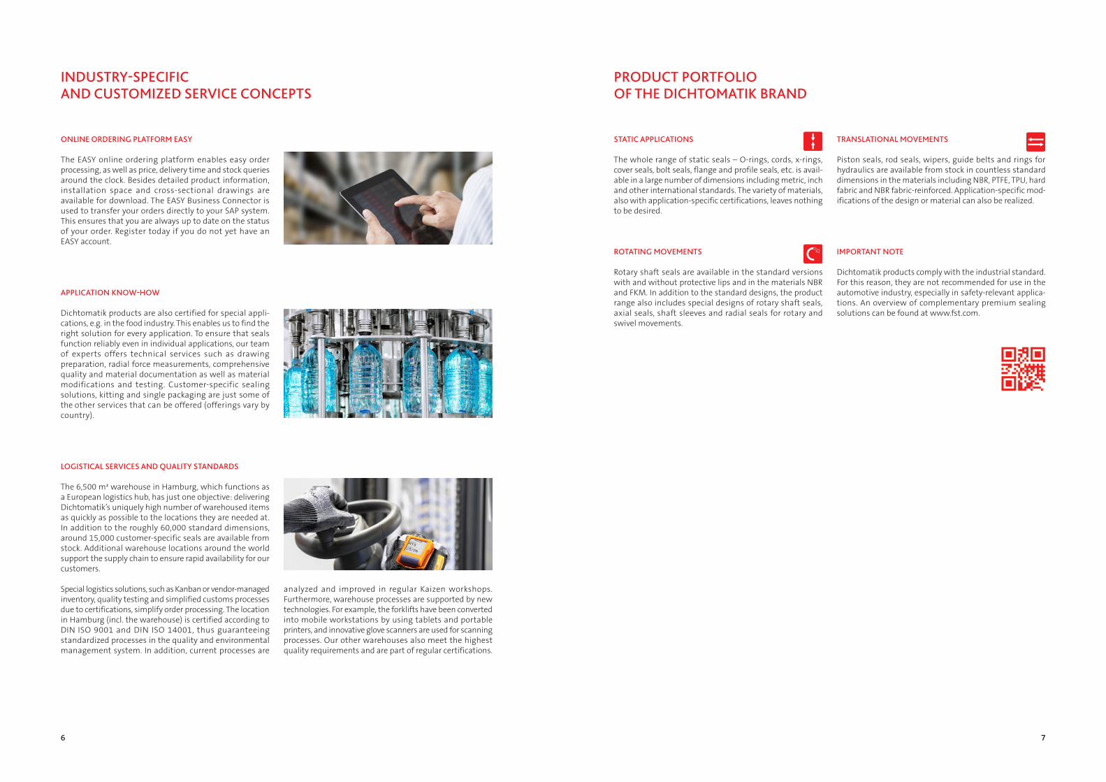
LOGISTICAL SERVICES AND QUALITY STANDARDS
The 6,500 m² warehouse in Hamburg, which functions as a European logistics hub, has just one objective: delivering Dichtomatik’s uniquely high number of warehoused items as quickly as possible to the locations they are needed at. In addition to the roughly 60,000 standard dimensions, around 15,000 customer-specific seals are available from stock. Additional warehouse locations around the world support the supply chain to ensure rapid availability for our customers.
Special logistics solutions, such as Kanban or vendor- managed inventory, quality testing and simplified customs processes due to certifications, simplify order processing. The location in Hamburg (incl. the warehouse) is certified according to DIN ISO 9001 and DIN ISO 14001, thus guaranteeing standardized processes in the quality and environmental management system. In addition, current processes are
analyzed and improved in regular Kaizen workshops. Furthermore, warehouse processes are supported by new technologies. For example, the forklifts have been converted into mobile workstations by using tablets and portable printers, and innovative glove scanners are used for scanning processes. Our other warehouses also meet the highest quality requirements and are part of regular certifications.
ONLINE ORDERING PLATFORM EASY
The EASY online ordering platform enables easy order processing, as well as price, delivery time and stock queries around the clock. Besides detailed product information, installation space and cross-sectional drawings are available for download. The EASY Business Connector is used to transfer your orders directly to your SAP system. This ensures that you are always up to date on the status of your order. Register today if you do not yet have an EASY account.
STATIC APPLICATIONS
The whole range of static seals – O-rings, cords, x-rings, cover seals, bolt seals, flange and profile seals, etc. is avail-able in a large number of dimensions including metric, inch and other international standards. The variety of materials, also with application-specific certifications, leaves nothing to be desired.
ROTATING MOVEMENTS
Rotary shaft seals are available in the standard versions with and without protective lips and in the materials NBR and FKM. In addition to the standard designs, the product range also includes special designs of rotary shaft seals, axial seals, shaft sleeves and radial seals for rotary and swivel movements.
TRANSLATIONAL MOVEMENTS
Piston seals, rod seals, wipers, guide belts and rings for hydraulics are available from stock in countless standard dimensions in the materials including NBR, PTFE, TPU, hard fabric and NBR fabric-reinforced. Application-specific mod-ifications of the design or material can also be realized.
IMPORTANT NOTE
Dichtomatik products comply with the industrial standard. For this reason, they are not recommended for use in the automotive industry, especially in safety-relevant applica-tions. An overview of complementary premium sealing solutions can be found at www.fst.com.
APPLICATION KNOW-HOW
Dichtomatik products are also certified for special appli-cations, e.g. in the food industry. This enables us to find the right solution for every application. To ensure that seals function reliably even in individual applications, our team of experts offers technical services such as drawing preparation, radial force measurements, comprehensive quality and material documentation as well as material modifications and testing. Customer-specific sealing solutions, kitting and single packaging are just some of the other services that can be offered (offerings vary by country).
8 9
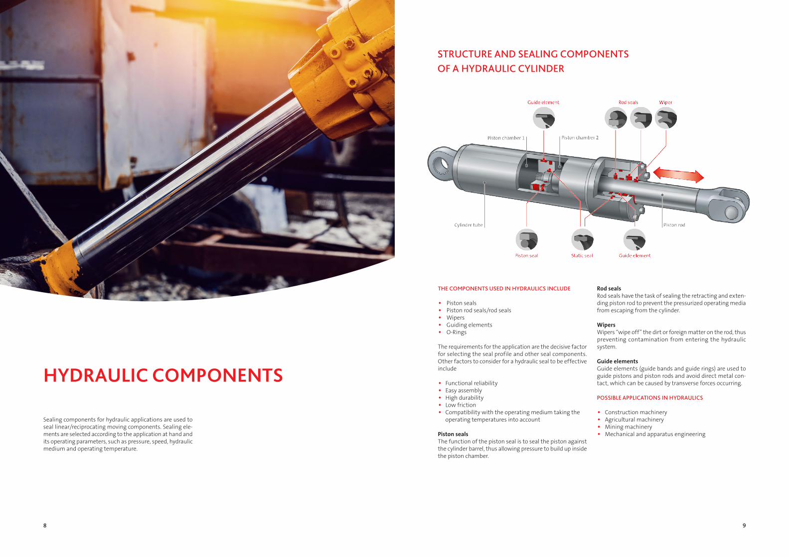
Rod�sealsRod seals have the task of sealing the retracting and exten-ding piston rod to prevent the pressurized operating media from escaping from the cylinder.
WipersWipers “wipe off” the dirt or foreign matter on the rod, thus preventing contamination from entering the hydraulic system.
Guide�elementsGuide elements (guide bands and guide rings) are used to guide pistons and piston rods and avoid direct metal con-tact, which can be caused by transverse forces occurring.
POSSIBLE APPLICATIONS IN HYDRAULICS • Construction machinery • Agricultural machinery • Mining machinery • Mechanical and apparatus engineering
Sealing components for hydraulic applications are used to seal linear/reciprocating moving components. Sealing ele-ments are selected according to the application at hand and its operating parameters, such as pressure, speed, hydraulic medium and operating temperature.
HYDRAULIC COMPONENTS
THE COMPONENTS USED IN HYDRAULICS INCLUDE • Piston seals • Piston rod seals/rod seals • Wipers • Guiding elements • O-Rings
The requirements for the application are the decisive factor for selecting the seal profile and other seal components. Other factors to consider for a hydraulic seal to be effective include
• Functional reliability • Easy assembly • High durability • Low friction • Compatibility with the operating medium taking the operating temperatures into account
Piston�seals�� �The function of the piston seal is to seal the piston against the cylinder barrel, thus allowing pressure to build up inside the piston chamber.
STRUCTURE AND SEALING COMPONENTS OF A HYDRAULIC CYLINDER

10 11
Assembly Type Description
N (N) U-Cup symmetrical
K NA
(K) Piston Seal
(N) U-Cup asymmetrical
(A) Outer sealing
S NI
(S) Rod Seal
(N) U-Cup asymmetrical
( I ) Sealing inside
K K (K) Piston seal compact
K;S POR(K;SPOR) Pistons; Rod PTFE seal
with an O-Ring preload element
K PUOR(KPUOR) Piston polyurethane seal
with an O-Ring preload element
K;S DS (K;SDS) Pistons; Rods roof cuff set
A E (AE) Wiper single-acting
A M(AM) Wiper with a metal reinforcement (metal seat/metal-reinforced)
A D (AD) Wiper double acting
A DM(ADM) Wiper double-acting with a metal reinforcement (metal seat/metal-reinforced)
G GS (GS) Guide strip
F RK (FRK) Guide ring piston
F RS (FRS) Guide ring rod
INTRODUCTION TO THE DESIGNATIONS
Designations�of�our�hydraulic�seals
Our�nomenclature�N = U-Cup K = Piston seal S = Rod seal A = Wiper F = Guide elements
Types��Within the assemblies listed above, we distinguish between the following types:
DIMENSIONS
Rod seals, piston seals, wipers and guide elements are always defined according to the installation space dimen-sion. This means that the size specifications of the seal cor-respond to the sizes of the installation space and that the installation space and not the seal is always measured.
We also provide the H dimension (measured width of the seal) for many of our piston and rod seals.
For piston seals and piston guide rings, the outside dia-meter AD (cylinder barrel diameter) is always listed as the first dimension (reference dimension); the inside diameter ID (rod diameter) is always listed for rod seals, rod guide rings and wipers.
Examples:
KNA28: AD x ID x L 50 x 40 x 8 piston seal
SNI30: ID x AD x L 40 x 50 x 9 rod seal
H dimension

12 13
Hydraulic seals are manufactured with a so-called “profile preload” and radially compressed in the installation space. Hydraulic seals are therefore tight at rest due to the over-size and the resulting precompression pv. If the seal is then pressurized with the operating pressure p, this pressure is
added to the existing precompression pressure. The pres-sure at the sealing surface pd is therefore always greater than the pressure to be sealed:
pd�=�pv�+�p
SEALING FUNCTIONS
The critical point of a hydraulic system is the rod seal. Leakage of hydraulic fluid from the cylinder would prevent trouble-free opera-tion and lead to environmental damage, among other things.
The sealing mechanism between the dynamic sealing lip and the rod is based on the hydrodynamic processes in the sealing gap. When the sealing system starts to move, the liquid film is drawn off by the sealing lip. The resulting drag flow and hydrodynamic pressure buildup create the dynamic sealing gap. What remains is a thin lubricating film, the so-called residual oil film. This remaining but necessary liquid film, which is only a few μ thick, ensures low-friction operation and thus a long service life for the seal.
Experts speak of dynamic tightness when the oil film that has been dragged out is completely returned to the pressure chamber.
Rod�seals� �A rod seal must be both internally sealing (sealing to the rod) and externally sealing (on the outside diameter to the groove base, purely static) to prevent hydraulic fluid from escaping from the hydraulic system.
When arranging the rod seals, a distinction is usually made bet-ween a primary seal and a secondary seal. The primary seal’s main task is to withstand the operating pressure, while the secondary seal, subjected to the lower interspace pressure (< 5 MPa), reduces the residual oil film to a minimum.
Example: U-Cups can only be pressurized on one side. As a rule, pressurization on one side is sufficient to meet the requirements of a rod seal.
A piston seal provides dynamic and static sealing on the outside to the cylinder wall and statically to the groove base in the inner dia-meter. If the piston seal is subjected to system pressure, the sea-ling effect will also increase and the dynamic sealing lip will be pressed against the cylinder wall.
The requirement for a piston seal is usually pressurization on both sides. Compact seals, here using the K84 as an example, can be pressurized on both sides. The pressure load is applied alternately from both sides.
Static�installation�situation • the static sealing lip seals towards the installation space
• the dynamic sealing lip also seals against the rod in the stationary state
Rod�seal�uninstalled
Piston�seal�unassembled Static�installation�situation • the sealing element seals radially to the cylinder wall
• the contact pressure element creates the sealing effect and seals to the groove base
Dynamic�installation�situation • the sealing effect is increased by means of pressurization
• both sealing lips are pressed “out- wards”
Dynamic�installation�situation • pressure load compresses the seal according to the pressure direction
• the sealing effect increases
Static sealing lip
Dynamic sealing lip
Medium side
StangeRod
Vorspannelement
MediumMedium
DichtelementSealing element
MediumMedium
Energizer
DruckPressure
THE SEALING MECHANISM OF ROD SEALS – DYNAMIC SEALING MECHANISM
THE SEALING MECHANISM OF PISTON SEALS – STATIC SEALING MECHANISM
Stange
Druck
Rod
DruckPressure

14 15
The following principles apply to the design of the instal-lation space and should be strictly observed for troub-le-free operation and a long service life of the seal:
• rounded corners in the groove base (1) ensure correct seating of hydraulic seals
• rounded groove flank transitions (2) reduce the risk of gap extrusion
• the surface finish of the groove base (3) and the groove flanks (4) ensure a good sealing function
• compliance with the tolerances for the groove width (5), the installation chamfer (6) and the correct dimen-sions of the sealing gap on the non-pressure side (7)
• the surface condition of the mating surfaces (8) is lar-gely responsible for a stable sealing function
The parameters of installation spaces, e.g. dimensions, curves, tolerances, installation chamfers and surface finishes (surface roughness), are defined by the respective cylinder manufacturer. When replacing a seal, you must check whether the installation space has changed as a
result of operation. The required surface finishes in parti-cular must be observed and compared with our specifica-tions. Notches on the piston rod or traces of wear caused by abrasive substances must be assessed and, if necessary, repaired.
INSTALLATION SPACES AND CONSTRUCTIVE RECOMMENDATIONS

16 17
Wiper type AE, AD Wiper type AM, ADM
The radius R for wiper designs AE40 and AE42 is selected as follows, depending on the height of the wiper:
H [mm] ≤ 12 16 18 R [mm] ≤ 1.0 1.5 3.0
For wiper types AE41, AE47, AD48 and AD51, the radius is always R = 0.5 regardless of the wiper height.
The AD60 and AD61 wipers require an axi-ally accessible installation space with small diameters. With larger diameters, a closed installation space can be provided. Subse-quent calibration is recommended. Please refer to the following table for dimension G and radius R:
L 3.7 5 6 8.4 11 14 G 1.5 1.5 1.5 2.0 2.0 2.5 R 0.4 0.8 1.0 1.2 1.5 2.0
When using double wipers, depending on the subsequent sealing arrangement, a relief hole may be required through which the retained oil is pumped back into the system.
EXAMPLES FOR USE IN SPECIFIED INSTALLATION SPACES
U-Cups type N, NA, NI
Type POR, PUOR
Compact seal type K
Guide elements type GS, FRK, FRS
Roof collar sets type KDS 01, SDS 01
The wiper can be easily installed axially if the proper installation chamfer C is avai-lable according to the following table.
H [mm] C [mm] ≤ 4,5 0.6 5 0.6 6 0.8 7 0.8 8 1 9 1 10 1.4 12 1.8 14 2 16 2.4
Rod
Piston
Rod
Profile width S 6 7.5-10 12.5-15 [mm] Installation slope C 3 5 7.5
Profile width S 6 7.5-10 12.5-15 [mm] Installation slope C 3 5 7,5
Rod�d<�25�mm
Installation space must be freely
accessible
Piston
Rod
Piston
Piston
pierced groove
Rod�d�>�25�mmPiston

18 19
ASSEMBLY – WHAT NEEDS TO BE CONSIDERED
Even though the materials used for Dichtomatik brand hydraulic seals deliver excellent performance and are robust, special care is required during installation. Mecha-nical damage, especially to the sealing edge, can lead to lea-kage. In addition, each seal must be checked before instal-lation for damage or aging that may have already occurred during transport or storage.
Instructions�for�mounting:
1. In the case of single-acting seals, the seal must be installed with the preload side facing the pressure side
2. Insertion chamfers are absolutely necessary on the cylinder barrel and piston rod. The chamfer should have an angle of 20°. The recommended length C depends on the profile width S. This profile width results from S = (D-d)/2
For the installation of wipers in open installation spaces, the following installation slopes C are recommended in relation to the installation space height H for trouble-free installa-tion:
APPLICATION OF ASSEMBLY TOOLS FOR U-CUPS
For easier assembly and to prevent damage to the seal during assembly, we recommend using assembly sleeves/assembly cones. The sleeve is pushed over the area to be covered.
Installation�of�a�rod�seal
Installation�of�a�piston�seal
3. Edges must be free from burrs. Radii and chamfers must be manufactured according to the installation specifica-tions
4. Dust, dirt and metal chips must be removed carefully
5. Thread tips, installation grooves for guide elements and rough surfaces etc. should be covered using a mounting cone, otherwise the seal runs the risk of being damaged
6. The cylinder barrel, piston rod and seal must be greased or oiled before assembly. Make sure that the seal is com-patible with the medium (see resistance tool, QR code below)
7. Heating in oil or hot water to approx. +80 °C (please pay attention to resistance) makes materials more pliable and easier to expand for assembly. At a temperature of +80 °C to +120 °C, PTFE seals can be expanded much more easily in oil or hot water and then formed back (calibrated)
8. Any assembly tools used, such as expanding mandrels, assembly sleeves or calibration sleeves or calibration mandrels, should be made of soft material (e.g. POM) and be free from sharp edges
9. When mounting type N and NI rod seals in closed grooves, the minimum diameter d
min depends on the pro-
file width S: S=(D-d)/2
For rod seals d<25 mm, we recommend mounting in axially open installation spaces.
Standard dimensions of piston seals type N and NA can generally be mounted in closed or half-open installation spaces for sizes d>25 mm using a snap-on assembly. Fab-ric-reinforced piston seals and roof collar sets can only be mounted in axially open installation spaces.
Profile width S [mm]Length of the installation chamfer C [mm]
4 2
5 2.5
7.5 4
10 5
12.5 6.5
15 7.5
20 10
25 10
H [mm] C [mm]
≤ 4.5 0.6
5 0.6
6 0.8
7 0.8
8 1
9 1
10 1.4
12 1.8
14 2
16 2.4
S [mm] 4 5 6 7.5 10 12.5 15
dmin
25 30 40 50 80 100 120
The piston seal is then positioned over the cone in the instal-lation space with the aid of an expanding sleeve.
After installing the rod seal, the mounting sleeve prevents damage to the seal and wiper when inserting the rod.
Expansion sleeve (plastic, POM, for example)
Assembly cone (plastic or metal)
U-Cup
Assembly cone
Use our resistance tools to find out the compatibility of chemicals and cleaning agents

20 21
SPECIAL FEATURES FOR THE MATERIAL PTFE
Since PTFE has virtually no elastic properties, PTFE-pre-loaded sealing elements (SPOR30, SPOR31, KPOR30, KPOR31) must be installed with particular care and then be calibrated. Observe the following installation instructions:
Installation�of�piston�seals�in�an�enclosed�groove
Insert the O-Ring into the groove without torsion: We recommend the procedure already described for PTFE seals. In this case, the PTFE ring is pushed over a conical assembly aid with an expansion sleeve until it snaps into the groove to expand the ring. The deformation of the expanded PTFE ring is accelerated with a calibration sleeve or calibration pliers, the inside diameter of which corresponds to the cylinder barrel diameter.
Series depends on the L-dimension of the seal, please ask us for the series.
Installation�of�rod�seals�in�a�closed�groove�
Insert the O-Ring into the groove without twisting: Press the PTFE ring together in a kidney shape. No sharp kinks may be created while doing so. Insert the compressed PTFE ring into the groove. Calibrate with a mandrel..
SMALLEST MOUNTABLE NOMINAL GASKET SIZES IN AXIALLY CLOSED INSTALLATION SPACES [MM]
Seal�type�� Series
000 001 002 003 004 005
SPOR30 >12 >16 >19 >38 >70 >200
SPOR31 >12 >16 >19 >38 >70 >200
KPOR30 >8 >15 >25 >40 >60 >133
KPOR31 >8 >15 >25 >40 >60 >133
Seal�type�� Series
000 001 002 003 004
SNI43 >20 >30 >35 >40 >45
KNA44 >11 >17,5 >20 >28 >45
Seg height of the semi-enclosed installation
0.4 0.6 0.7 0.8 0.9
Calibration mandrel
SMALLEST MOUNTABLE NOMINAL GASKET SIZES IN SEMI-ENCLOSED INSTALLATION SPACES [MM]
Expanding mandrel (Plastic e. g. POM)
Expanding sleeve (Plastic or metal)
PTFE- profile ring
O-Ring
5°Calibration sleeve
(plastic or metal)
15°

22 23
NBR – ACRYLONITRILE BUTADIENE RUBBER
NBR is widely used in the hydraulic industry due to its good mechanical properties and resistance to mineral oil-based lubricating oils and greases. The material shows good mechanical-technological parameters, e.g. high abrasion resistance, low gas permeability and good resistance to lubricating oils and greases based on mineral oil, hydraulic oils H, HL, HLP, flame-retardant pressure fluids HFA, HFB, HFC, aliphatic hydrocarbons, silicone oils and greases, water up to approx. +80 °C. NBR, on the other hand, is generally not resistant to aromatic and chlorinated hydrocarbons, fuels with a high aromatics content, polar solvents, gly-col-based brake fluids and HFD flame-retardant pressure fluids. Ozone, weathering and aging resistance are low. However, this does not affect most hydraulic applications because the hydraulic seals are used in the hydraulic com-ponents.
TPU – THERMOPLASTIC POLYURETHANE
TPU materials belong to the group of thermoplastic elasto-mers (TPEs). The strength of TPUs lies in the combination of their good properties, both physical and chemical, as well as processing and economic. TPU materials stand out from classic elastomers due to their significantly higher mecha-nical strength. Other excellent material properties include high abrasion, wear and extrusion resistance, high com-pressive strength, high tear and tear propagation resistance, and very good resistance to aging and ozone. TPU is well suited for use in mineral oils and greases, hydraulic oils H, HL, HLP, silicone oils and greases, flame-retardant hydraulic fluids HFA and HFB and water up to +50 °C, as well as pure aliphatic hydrocarbons.
PTFE – POLYTETRAFLUOROETHYLENE
PTFE is a fluorinated plastic. PTFE has a wide range of posi-tive properties that have become indispensable in sealing technology. It is characterized by its virtually universal che-mical resistance, the wide temperature application range from -100 °C to +250 °C, an extremely low coefficient of fric-tion and the resulting very good sliding properties, no stick-slip effect, special rigidity and the nearly unlimited resistance to ozone, weathering and aging. Virtually all known hydraulic media, lubricants, chemicals and solvents cannot harm PTFE. Disadvantages of PTFE are the tendency to cold flow or creep of the pure PTFE under pressure load.
HARD FABRIC MATERIALS
Hard fabric materials are manufactured from various fabric/resin combinations, such as synthetic fiber fabric + phenolic resin, cotton fabric + phenolic resin or polyester fabric + polyester resin. Hard fabric materials are selected for applications in hydraulics with high loads and transverse forces.
NBR F – RUBBER FABRIC MATERIALS
Cotton or synthetic fiber fabrics can be used as the basis for rubber fabric materials. As standard, Dichtomatik brand products are made of cotton fabric for hydraulic seals. They have high wear resistance, very good friction and sliding properties (due to the lubricant embedded in the fabric lubrication pockets), good low-temperature resistance, and high resistance to pressure and extrusion.
Dichtomatik brand hydraulic seals are offered in elastomers, rubber-fabric materials, thermoplastic elastomers (TPEs), thermoplastics, and hard-fabric materials.
MATERIALS
You can find further material information on our website

24 25
Profile Type Material Hardness [Shore A] Temperature [°C] Sliding speed
[m/s] Pressure [MPa(bar)]
KNA28 TPU 95 -40 to +100 ≤ 0.5 40 (400)
N25 TPU 95 -40 to +100 ≤ 0.5 30 (300)
KNA23 NBR 90 -30 to +100 ≤ 0.5 16 (160)
N21 NBR 90 -30 to +100 ≤ 0.5 16 (160)
N36 TPU 95 -40 to +100 ≤ 0.5 40 (400)
N05 NBR 80 -30 to +100 ≤ 0.5 20 (200)
KNA16 NBR 80 -30 to +100 ≤ 0.5 50 (500)
KPOR30 PTFE -30 to +100 ≤ 15 40(400)
KPOR31 PTFE -30 to +100 ≤ 15 40 (400)
KK03 NBR 80 -30 to +100 ≤ 0.5 40 (400)
KK22 NBR 90 -30 to +100 ≤ 0.5 40 (400)
KDS01 NBR F 90 -30 to +100 ≤ 0.5 40 (400)
KNA44 PTFE -150 to +250 ≤ 15 35 (350)
K84 TPU 95 -30 to +100 ≤ 0.5 40 (400)
K70 TPU 95 -30 to +100 ≤ 0.5 25 (250)
Profile Type Material Hardness[Shore A] Temperature [°C] Max. speed [m/s] Max. pressure in
[MPa(bar)]
N21 NBR 90 -30 to +100 0.5 16 (160)
SNI24 NBR 90 -30 to +100 0.5 16 (160)
N05 NBR 80 -30 to +100 0.5 20 (200)
SNI07 NBR 80 -30 to +100 0.5 40 (400)
SDS01 3/2 NBR/NBR F * 90 -30 to +100 0.5 40 (400)
N25 TPU 95 -40 to +100 0.5 30 (300)
SNI30 TPU 95 -40 to +100 0.5 40 (400)
SNI39 TPU 95 -40 to +100 0.5 40 (400)
N36 TPU 95 -40 to +100 0.5 40 (400)
S72 TPU 95 -30 to +100 0.5 40 (400)
SNI35 TPU 95 -40 to +100 0.5 40 (400)
SPOR30 PTFE-bronze -30 to +100 15 40 (400)
PROFILE OVERVIEW
PISTON SEALS
Note: The values listed here are maximum values. These may not all be reached at the same time.
* F: fabric (fabric-reinforced material)
ROD SEALS

26 27
Profile Type Material Hardness[Shore A]
Temperature [°C] Color Sliding speed
[m/s] Single-acting Double-acting
AE40 NBR 90 -30 to +110 black ≤ 1 X
AE41 NBR 90 -30 to +110 black ≤ 1 X
AM43 NBR 90 -30 to +110 black ≤ 1 X
AM45 NBR 90 -30 to +110 black ≤ 1 X
AD51 NBR 90 -30 to +110 black ≤ 1 X
AE42 TPU 90 -40 to +100 blue ≤ 2 X
AE47 TPU 90 -40 to +100 blue ≤ 2 X
AM44 TPU 95 -40 to +100 blue ≤ 2 X
AM54 TPU 95 -40 to +100 blue ≤ 1 X
AD48 TPU 95 -40 to +100 blue ≤ 1 X
ADM55 TPU 95 -40 to +100 blue ≤ 1 X
AD60PTFE bronze
-30 to +100 ≤ 15 X
AD61PTFE bronze
-30 to +100 ≤ 15 X
AE80PTFE bronze
-30 to +100 ≤ 15 X
Profile Type Material Surface Delivery condition
Sliding speed [m/s]
Dyn. surface pressure [N/mm²]
Compressive strength [N/mm²]
Temperature [°C]
GS01PTFE bronze filled
structured Roll ≤ 15 ≤ 15 ≤ 25 -60 to +200
GS10PTFE bronze filled
smooth Roll ≤ 15 ≤ 15 ≤ 25 -60 to +200
FRK01PTFE bronze filled
structured Strips, cut 30° ≤ 15 ≤ 15 ≤ 25 -60 to +200
FRS01PTFE bronze filled
structured Strips, cut 30° ≤ 15 ≤ 15 ≤ 25 -60 to +200
GS05Hard fabric with PTFE
smooth Roll ≤ 1 ≤ 100 ≤ 350 -50 to +120
FRK05Hard fabric with PTFE
smoothRing, bevel cut 45°
≤ 1 ≤ 100 ≤ 350 -50 to +120
FRS05Hard fabric with PTFE
smoothRing, bevel cut 45°
≤ 1 ≤ 100 ≤ 350 -50 to +120
* F: fabric (fabric-reinforced material)
GUIDE ELEMENTS, PISTONS AND RODSWIPERS
Note: The values listed here are maximum values. These may not all be reached at the same time.

Editorial information
Freudenberg�FST�GmbHHöhnerweg 2-469469 Weinheim, Germany
Published by
Freudenberg�Industrial�Services�GmbHAlbert-Schweitzer-Ring 122045 Hamburg, GermanyTel. +49 40 669 89 [email protected] | dichtomatik.fst.com
Publication�dateJuly 2021
Picture�credits�Page�6�bottomWorkaround GmbHRupert-Mayer-Str. 4481379 München