sea perch project - mit sea perch
TRANSCRIPT

Sea Star
Surface Craft Construction Manual
DRAFT

UNIT 1
DESIGNING AND MANUFACTURING THE HULL
FOR THIS UNIT YOU WILL NEED: Tools Materials Pencil & Eraser Ruler Scissors Felt-tip marker Hot Wire Foam Cutters (Sculpting Tool and Hot Knife) Fine sand paper
Design Paper Foam Block

STEP 1 PURPOSE: To Design the shape of the hull. MATERIALS: Design Paper TOOLS: Pencil Eraser Ruler
Figure 1.1: Example of a three-view design of a basic boat. PROCEDURE:
1. Familiarize yourself with the basics of boat hull design, including the many types of
hulls and their characteristics and variations. Refer to the MIT Sea Grant Hull Design document provided with this manual. There are many other resources available on hull design, including the books and web pages referenced on the following page.
2. On a large piece of paper, trace your block of foam from all three sides (side view, top view, and one or more end-on views representing one or more cross sections across the hull).
3. Decide on the type of hull you want to design, and what performance characteristics you wish to achieve.
4. From each of the three angles, draw your desired hull shape within the traces of your foam block.

Books on Boat Design: Introduction to Naval Architecture, by Thomas C. Gillmer and Bruce Johnson. From the Naval Institute Press, Annapolis Maryland, 1982. Understanding Boat Design, Fourth Edition., by Edward S. Brewer. From International Marine, Camden, Maine, 1994. How To Design a Boat, Second Edition, by John Teale. From Sheridan House, Dobbs Ferry, New York, 1998. Yacht and Small Craft Design: From Principles to Practice, by Gordon Trower. From the Crowood Press, Wiltshire, U.K., 1993. Devlin’s Boatbuilding: How to Build Any Boat the Stictch-and-Glue Way, by Samual Devlin. From International Marine, Camden, Maine, 1996. Sailing Yacht Design: Theory, Edited by Claughton, Wellicome & Shenoi. From Addison Wesley Longman Limited, Essex, England, 1998. Websites with information on boat design: http://www.boatdesign.net/ http://boatdesign.net/articles/tunnel-hull-design/ http://powerboat.about.com/od/hulls/a/displacement.htm http://powerboat.about.com/od/maintenance/l/aa012403b.htm Basic Design Equations: http://www.johnsboatstuff.com/Articles/design.htm Canoe hull design: http://www.heritagecanoes.com/hull.html http://sites.state.pa.us/PA_Exec/Fish_Boat/anglerboater/1999/julaug99/boathull.htm

STEP 2 PURPOSE: To transfer the design to the foam. MATERIALS: Design Paper Foam block TOOLS: Scissors Felt-tip marker
Figure 1.2: Hull design transferred to foam block.
PROCEDURE:
1. Cut out the sketches of your hull design using the scissors. 2. Place the sketches on your foam block one at a time, and trace them onto the foam
with the marker.

STEP 3 PURPOSE: To carve the foam. MATERIALS: Foam block TOOLS: Hot Wire Hot Knife and Sculpting Tool
Figure 1.3: Hot Wire Hot Knife (top left), Sculpting Tool (top right), and carving the foam (bottom)
PROCEDURE:
1. Using the Hot Wire tools, and following the lines drawn on your foam, cut the foam
to the desired hull shape. 2. WARNING: Avoid excessive breathing of the vapors produced by the Hot Wire
tools. Use only in a well ventilated room! 3. For complex hull shapes, take care to keep enough material for strength. 4. Do not cut too deeply into the top of the hull, as you will need places to mount the
transom and control system. Refer to Units 2 and 3 for what will be needed.

STEP 4 PURPOSE: To smooth the foam. MATERIALS: Carved Foam Hull TOOLS: Hot Wire tools Fine sand paper
Figure 1.4: Smoothing the foam hull.
PROCEDURE:
Nearly as important to the performance of a boat as the shape of the hull is the finish on the surface. 1. Use the fine sand paper and the Hot Wire tools to carefully create a smooth finish on
the surface of your hull. 2. Take care not to create rough spots with the sandpaper, or to remove too much
material with the Hot Wire tools.

UNIT 2
MOUNTING THE POWER SYSTEM
FOR THIS UNIT YOU WILL NEED: Tools Materials Ruler Felt-tip marker Saw Xacto Knife with long (whittling) blade Hot Wire Hot Knife Needle Nose Pliers Drill Drill Bit Screw Driver
Carved Hull Transom Plate (Plastic or wood) Motor Assembly Screws and Nuts, 4 each Glue

STEP 1 PURPOSE: To measure and cut the transom to the appropriate size and shape. MATERIALS: Carved Hull Transom Plate Motor Assembly TOOLS: Ruler Felt-tip marker Saw
Figure 2.1:Transom cut to size and shape. PROCEDURE:
The transom is the board that makes up the back of the boat, to which the outboard motor is mounted. The transom is mounted 1/2 inch from the back of the boat, so that there is 1/2 inch of foam remaining between the transom and the back of the boat. The motor needs to be mounted so that the propeller is completely submerged up to the stabilizer fins. 1. Place the hull in water to see where the waterline is. You may want to add some
weight approximately equivalent to that of the motor, battery, control system, and any anticipated ballast.
2. Mark the approximate water line in the back of the boat. 3. Remove the boat from the water and hold the motor up against the back of the boat in
its desired location. Mark the area of the back of the boat that will need to be cut out to accommodate the motor mount.
4. Measure the needed size of the transom and mark the measurements on the transom plate. Remember that the motor must be properly submerged, and the transom must be well embedded in the foam, to create a strong connection for the transfer of power. For maximum strength, make the transom as large as possible, without requiring cuts in the hull that would weaken it. Also remember that the steering linkages must pass over or through the transom, so provide space for them.
5. Using the saw, cut the transom to the correct size and shape. Wear safety glasses and watch your fingers!
STEP 2 PURPOSE: To carve the space in the hull where the transom and motor will be mounted. MATERIALS: Carved Hull Transom Motor Assembly TOOLS: Felt-tip marker Xacto Knife Hot Knife Needle Nose Pliers
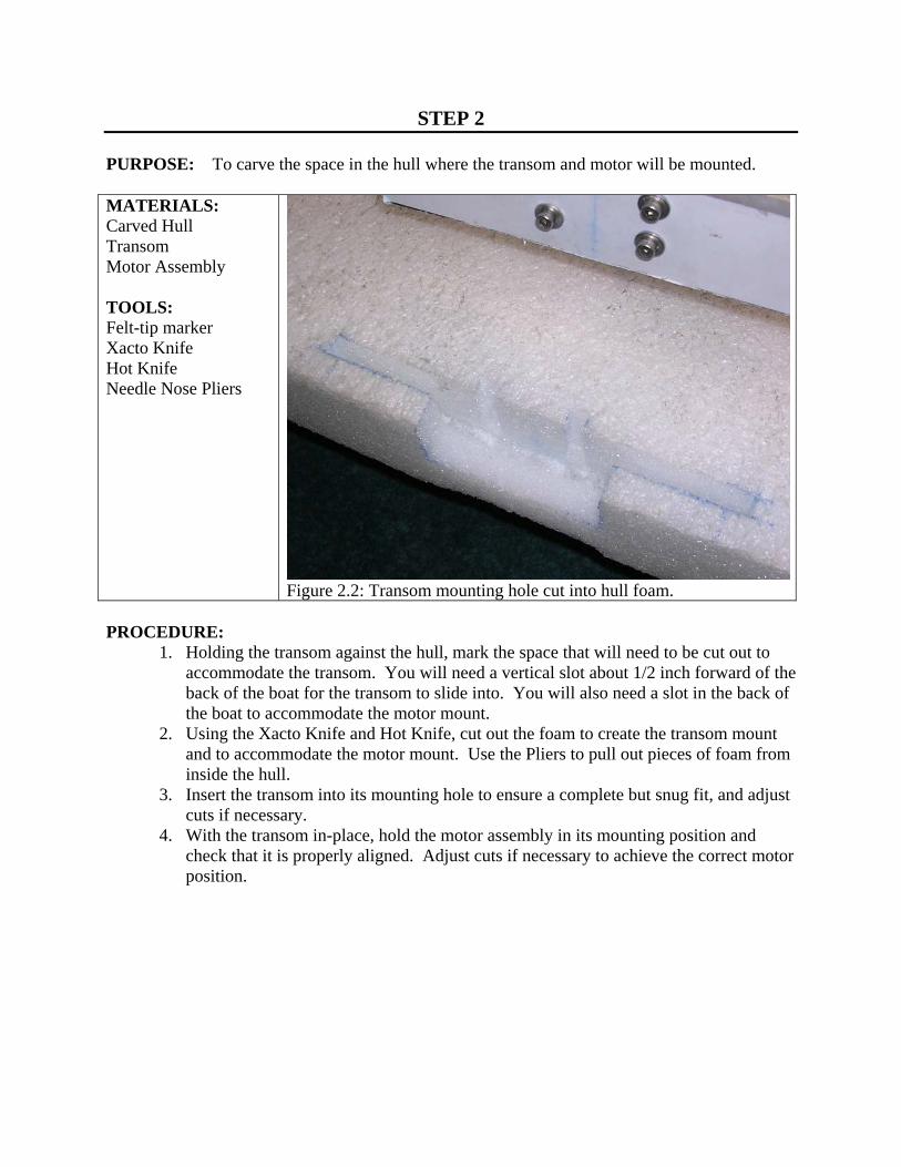
Figure 2.2: Transom mounting hole cut into hull foam. PROCEDURE:
1. Holding the transom against the hull, mark the space that will need to be cut out to accommodate the transom. You will need a vertical slot about 1/2 inch forward of the back of the boat for the transom to slide into. You will also need a slot in the back of the boat to accommodate the motor mount.
2. Using the Xacto Knife and Hot Knife, cut out the foam to create the transom mount and to accommodate the motor mount. Use the Pliers to pull out pieces of foam from inside the hull.
3. Insert the transom into its mounting hole to ensure a complete but snug fit, and adjust cuts if necessary.
4. With the transom in-place, hold the motor assembly in its mounting position and check that it is properly aligned. Adjust cuts if necessary to achieve the correct motor position.
STEP 3 PURPOSE: Mount motor to transom MATERIALS: Transom Screws and Nuts TOOLS: Felt-tip marker Drill Drill Bit Screw Driver Pliers
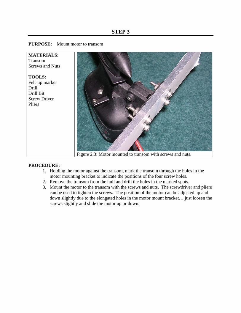
Figure 2.3: Motor mounted to transom with screws and nuts. PROCEDURE:
1. Holding the motor against the transom, mark the transom through the holes in the motor mounting bracket to indicate the positions of the four screw holes.
2. Remove the transom from the hull and drill the holes in the marked spots. 3. Mount the motor to the transom with the screws and nuts. The screwdriver and pliers
can be used to tighten the screws. The position of the motor can be adjusted up and down slightly due to the elongated holes in the motor mount bracket… just loosen the screws slightly and slide the motor up or down.
STEP 4 PURPOSE: Mount transom to hull. MATERIALS: Transom Screws and Nuts TOOLS: Xacto Knife Hot Knife Glue
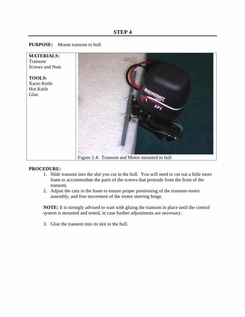
Figure 2.4: Transom and Motor mounted to hull
PROCEDURE:
1. Slide transom into the slot you cut in the hull. You will need to cut out a little more foam to accommodate the parts of the screws that protrude from the front of the transom.
2. Adjust the cuts in the foam to ensure proper positioning of the transom-motor assembly, and free movement of the motor steering hinge.
NOTE: It is strongly advised to wait with gluing the transom in place until the control system is mounted and tested, in case further adjustments are necessary. 3. Glue the transom into its slot in the hull.

UNIT 3
INSTALLING THE CONTROL SYSTEM
FOR THIS UNIT YOU WILL NEED: Tools Materials Ruler Felt-tip marker Hot Wire Hot Knife Xacto Knife (No.2 handle w/Whittling blade) Xacto Kinfe (w/small blade) Small Needle Nose Pliers
Foam Hull with Transom and Motor Mounted RC Receiver w/ antenna cable Receiver battery pack w/switch Steering Servo Steering Links Motor Controller w/switch Battery Charger Velcro Antenna Mast Electrical Tape

STEP 1 PURPOSE: To mount the steering servo and linkages MATERIALS: Carved Hull Mounted Transom Steering linkages Steering servo Electrical Tape TOOLS: Ruler Felt-tip marker Xacto Knife Hot Wire Hot Knife Needle-nose pliers
Figure 3.1: Steering Linkages PROCEDURE:
The steering servo should be mounted in the (side to side) center of the boat, and just far enough forward to put a little bit of tension on the steering linkages when assembled. Note: a servo is a motor that is used to move something in a control system. The servos that come with your R/C system are small boxes with star shaped attachments on top. 1. Assemble the steering linkages by screwing the linkage ball studs to the rods. They
should be screwed on about 1/2 way, for maximum adjustability. 2. Attach the steering linkages to the steering balls on the motor by pushing one of the
studs onto each ball. Position the linkages forward to see where they will have to go. 3. Start cutting the hole in the top of the hull to accommodate the servo and linkages. If
you have a deep (>2 inches) hull, you will likely have to mount the servo below the deck level, and cut a slot for the steering linkages. Keep testing the position of the servo and cutting until you have the correct hole for the servo.
4. Make sure the servo has enough room to turn unobstructed, and the linkages can move unobstructed.
5. Wrap the steering servo in electrical tape to minimize water entry should it get wet. 6. Insert the servo into its mounting hole and connect the steering linkages. The length
of the linkages can be adjusted using the screw attachment of the linkage ball studs. They can also be bent slightly to ensure a slip-free connection to the servo.

STEP 2 PURPOSE: To modify the motor controller cable MATERIALS: Motor controler Electrical tape TOOLS: Any sharp, pointed object
Figure 3.2: Motor Controller with modified connector (lower right). PROCEDURE:
As described in the motor controller instructions, there are two ways to supply power to the R/C receiver and servo. One uses power from the main battery through the motor controller, which eliminates the weight of the extra batteries, but risks loosing control of the vehicle should the main battery power suddenly drop. The second method uses the 4-AA battery pack that comes with the R/C system. This method is recommended, since it allows the R/C system to continue working after the main battery power drops. When used in this second configuration, the motor controller connector cable must be modified as described below, to avoid short circuits in the power system. 1. Find the connector from the motor controller which plugs into the R/C receiver and
note the three leads. One should be red (power), one black (ground), and one white (signal). As indicated in the motor controller instructions, the power lead must be disconnected when using separate batteries to power the R/C system.
2. Use a sharp object to nudge back the retaining clip on the red wire’s contact, and pull on the red wire to slide the metal contact out of the plastic connector housing.
3. Wrap the loose contact with electrical tape to avoid short circuits.

STEP 3 PURPOSE: To lay out the control system MATERIALS: Carved Hull with mounted transom and motor Control system components Dry box TOOLS: Ruler Felt-tip marker
Figure 3.3: Motor controller and battery in optimal layout.
PROCEDURE:
Most of the control system will be mounted inside the dry-box. This includes the R/C receiver, the receiver battery and switch, and the motor controller and switch. The position of the motor controller should be chosen to maximize the forward positioning of the battery, but the rest of the items can be positioned as convenient. The battery needs to be mounted as far forward as possible to counteract the weight of the motor. The motor cables from the motor controller to the motor should be nearly completely extended, with just enough slack to allow for the full movement of the motor when steering, and to allow for passage of the wires through the dry box. The battery cable from the battery to the motor controller should also be fully extended to get the battery as far forward as possible. If the box is long enough, the battery can be mounted inside. If the boat is still too heavy in the back, an extension cable can be purchased or created for the battery. For a dry box, we used a “Glad” brand plastic food container about 6x6x2 inches in size. Any similarly sized plastic container should work. 1. Make sure the motor controller switch is turned OFF. 2. Lay out the dry box, motor controller, and battery on the deck of the boat, keeping in
mind the notes above about maximizing the forward positioning of the battery. The battery should be centered side to side in the boat for balance, and as far forward as possible to counteract the weight of the motor.
3. Make sure there is room in the dry box for the other components (R/C receiver, battery pack, switches).
4. Outline the positions of the battery and the dry box on the deck using the marker.

STEP 4 PURPOSE: Mount the dry box, control system, and battery. MATERIALS: Carved Hull with mounted transom and motor Control system components Dry box TOOLS: Xacto Knife Hot Wire Hot Knife Needle-nose pliers
Figure 3.4: Control system installed in custom-cut holes in hull.
PROCEDURE:
1. Using the Xacto Knife and Hot Wire, cut out the appropriate holes as marked on the deck of the boat to accommodate the dry box and battery. The pliers can be used to pull foam out of the holes if it is not completely cut off on the bottom.
2. Test the mounting holes by inserting the battery and dry box to see how they fit. Adjust the cuts as necessary.
3. Using the Xacto Knife, cut a hole in the front of the dry box to pass the battery cable through. Cut a hole in the back of the dry box to pass the motor power cables, the steering servo cable, and the antenna cable through. Keep these holes as small as possible, while still allowing the cable connectors to pass through.
4. Cut slots in the deck to pass the wires through as necessary. 5. Cover the holes in the dry box with electrical tape to minimize water entry. 6. Mount the battery and dry box in their holes using strips of Velcro. 7. Mount the control system components inside the dry box using Velcro strips.

STEP 5 PURPOSE: Complete the control system MATERIALS: Carved Hull with mounted transom, motor, battery and dry box Antenna mast Electrical Tape TOOLS: Screwdriver
Figure 3.5: Completed control system.
PROCEDURE:
1. Make sure that both power switches are turned OFF. 2. Pass the battery cable from the battery through the hole in the front of the dry box. 3. Pass the motor power cables from the motor controller through the hole in the back of
the dry box. Pass the cable from the steering servo and the antenna cable from the receiver through the hole in the back of the dry box.
4. Connect the control system as shown in the wiring diagram (following page). 5. Using a screwdriver or other sharp object, poke a hole in the deck of your boat to
mount the antenna mast. It should be in the center of the boat, near the hole in the back of the dry box.
6. Wrap the antenna cable around the mast and tape the end to the top using a small piece of electrical tape.
STEP 6 PURPOSE: Test and adjust the system MATERIALS: Carved hull with assembled control system TOOLS: Battery Charger
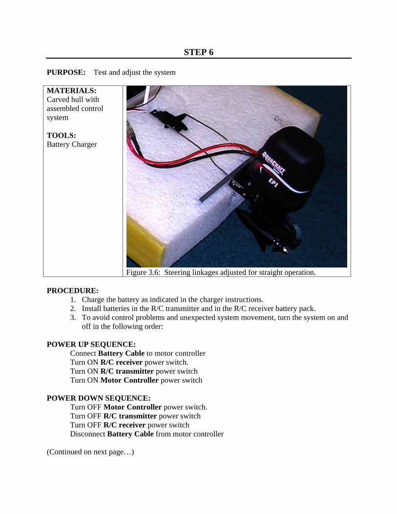
Figure 3.6: Steering linkages adjusted for straight operation. PROCEDURE:
1. Charge the battery as indicated in the charger instructions. 2. Install batteries in the R/C transmitter and in the R/C receiver battery pack. 3. To avoid control problems and unexpected system movement, turn the system on and
off in the following order: POWER UP SEQUENCE: Connect Battery Cable to motor controller Turn ON R/C receiver power switch. Turn ON R/C transmitter power switch Turn ON Motor Controller power switch POWER DOWN SEQUENCE: Turn OFF Motor Controller power switch. Turn OFF R/C transmitter power switch Turn OFF R/C receiver power switch Disconnect Battery Cable from motor controller (Continued on next page…)

4. When you turn on the system, the motor will spin briefly. If it keeps spinning, adjust the position adjustment on the throttle control stick on the transmitter. The motor should be stopped when the throttle control stick is in the center (released) position.
5. Adjust the steering system so that the motor is centered when the steering control stick is in the center (released) position. There are three adjustment points: For gross adjustments, the cross shaped bracket on the steering servo can be rotated on the servo by removing the retention screw, adjusting the position, and replacing the screw. For medium adjustments, the steering linkage ball studs can be adjusted by removing them from the balls and twisting them in or out to lengthen or shorten the linkages. For fine adjustments, use the adjustment control on the R/C transmitter.
6. Check that the steering and motor move in the expected directions when the control sticks are moved. If they move in the opposite directions, the reversal switches in the transmitter battery compartment must be switched.
7. Close the dry box by attaching the lid and pressing it in place securely. Place the boat in water and ensure that it floats in an upright and stable manner. If it is unstable, it may need to lower its center of gravity. This can be achieved by placing the battery and dry box deeper in the hull, or adding ballast weight in a deep hole in the hull.