se 430 object oriented modeling dennis mumaugh, instructor [email protected] office: cdm, room...
TRANSCRIPT
SE 430 SE 430 Object Oriented ModelingObject Oriented Modeling
Dennis Mumaugh, Instructor
Office: CDM, Room 432
Office Hours: Thursday, 4:00 – 5:30
September 24, 2015 SE 430: Lecture 3 1 of 94
AdministriviaAdministrivia Comments and/or Feedback Email – make sure your email address on campus
connection is correct! At least one student has an email that bounces!
For documents to be submitted: be sure any embedded figures are JPEG.
Assignments: You may use the solutions from the previous assignment(s) as a
basis for work on your next assignment Solutions for assignments will be posted the next day (evening) after
they are due.
September 24, 2015 SE 430: Lecture 3 2 of 94
September 24, 2015 SE 430: Lecture 3
Assignment 2Assignment 2Assignment 2 (Due October 1) Visitor Information Subsystem: Subsystem Use Cases and Use-case
supplemental diagram. Produce the use-case model for the Visitor Information subsystem Deliverables:
Cover page List of all actors, their goals and objectives Identification of use cases Brief descriptions of all use cases – see template Ranking of use cases and basis of ranking Use case diagram (all use cases – together). Detailed use case: (Fully dressed or expanded) description of major
use case Use-Case Supplemental Diagram (system sequence diagram) Glossary
Forms that you may elect to use are on the reading list page.
3 of 94

Term ProjectTerm Project Team Project Preliminary Description discusses the first deliverable.
Due (Due October 22) Preliminary project description – Team Project – Preliminary Descript
ion.doc http://condor.depaul.edu/dmumaugh/se430/assignments/Team Project – Preliminary Description.doc
List of primary use cases Team Project
Due (Due November 19) http://condor.depaul.edu/dmumaugh/se430/assignments/TeamProjec
t.doc See the course documents page
Team assignments are on the course documents page on D2L.
September 24, 2015 SE 430: Lecture 3 4 of 94
ProjectsProjects Some sort of personal productivity enhancer
Smart phone or iPad application
StarTrek™ Tri-corder Field work support: GPS, pictures, documents, portable science lab
Smart shopper device UPS delivery tracking or OTR Truck dispatch Guide for the blind
September 24, 2015 SE 430: Lecture 3 5 of 94
September 24, 2015 SE 430: Lecture 3
ProjectProjectFormat of document Make sure each page is numbered and has name of project
and submission info Use standard “business” report formats Proofread your documents! Check that the submission contains all that is asked for and
in the correct (logical) order. Maximum size of submission is 25 pages or less, preferably
less!
6 of 94
Project HintsProject Hints Get organized ASAP and have some meetings. You have three weeks to
decide on a project, develop requirements, use-cases and write-it up. If possible, have some face to face meetings There are collaboration groups for each team.
Email list for each team Project collaboration site
Group drop outs: Reduce scope of project. Cover less use cases: max (<groupSize>-1, 2) Notify me ASAP if a team member is not working or seems to have
dropped out. How (not) to lose in SE 430
Read the paper and follow it. (Not!) Make a schedule and follow it. Try to pace yourselves and keep
making progress.
September 24, 2015 SE 430: Lecture 3 7 of 94
September 24, 2015 SE 430: Lecture 3
Project: Working in groupsProject: Working in groups Rotate responsibilities Have a moderator and a recorder at each meeting
Moderator keeps meeting on track, keeps track of action items Recorder keeps good notes
Allow contributions from all members Project is a learning process as well as just a job Need to make sure all are on board Use the Amerindian tradition of the "Talking Stick"
Be careful not to overwhelm people. Tell people if you feel you are
Being ignored Not given enough work or too simple work.
Make a schedule of work and action items (deliverables, both internal and external) Keep communicating. Answer your mail promptly.
8 of 94

September 24, 2015 SE 430: Lecture 3
SE 430 – Class 3SE 430 – Class 3Topic: Use-Case Model
Concepts and Background The Use-Case Model in the Unified Process
» High level use cases Use-Case Workflow Use-Case Tasks and Artifacts
» Use Case Diagrams » Ranking Use Cases » Detailed Use Cases
System Sequence Diagrams
Reading:
Arlow & Neustadt: Ch’s 4 & 5
Class reading list
9 of 94

September 24, 2015 SE 430: Lecture 3
Thought for the DayThought for the Day
"Never ask users what they want, or they'll tell you."
10 of 94

September 24, 2015 SE 430: Lecture 3
Last TimeLast TimeTopics: Requirements Analysis
Defining Requirements Problem Statement or Project Charter or Vision Requirements Document
» Formal list of what the product will do
Business and Domain Rules Activity Diagrams
11 of 94

September 24, 2015 SE 430: Lecture 3
Big PictureBig Picture
Today
12 of 94
Object-Oriented ModelingObject-Oriented Modeling
September 24, 2015 SE 430: Lecture 3 13 of 94

What is a model?What is a model? A model is an abstraction which strips away unnecessary details, and
views an entity from a particular perspective This is another application of the just right principle: include just what you
need for the problem at hand, no more, no less
Models allow us to: Focus on the important parts of the entity Ignore parts of the entity that are irrelevant Hypothesize and reason about the entity
Paraphrased from Software Measurement and Estimation: A Practical Approach, L.M. Laird & M.C. Brennan, 2006
September 24, 2015 SE 430: Lecture 3 14 of 94
A fundamental modeling principleA fundamental modeling principle
“Models are not right or wrong, they are more or less useful.”
- Martin Fowler
September 24, 2015 SE 430: Lecture 3 15 of 94

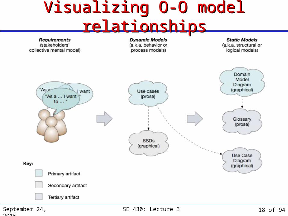
Types of object-oriented analysis modelsTypes of object-oriented analysis models Requirements capture the needs and wants of various stakeholders and
formalize them as user stories Requirements represent a collective mental model of the system
viewed from the stakeholders' perspective‣ Everyday mental model example: Thermostats of different sorts
The use-case model—use cases and system sequence diagrams— models the dynamic/behavioral/process-oriented aspects of the system However, the use case diagram is a static diagram that models the
static relationships among actors and use cases The domain model—diagram and glossary—models the
static/structural/logical aspects of the system Domain processes are modeled in both the use case model and in the
domain model
September 24, 2015 SE 430: Lecture 3 16 of 94

Domain processes: static and dynamic representationsDomain processes: static and dynamic representations
Domain processes are modeled statically in the domain modeland dynamically in use cases
September 24, 2015 SE 430: Lecture 3 17 of 94
Visualizing O-O model relationshipsVisualizing O-O model relationships
September 24, 2015 SE 430: Lecture 3 18 of 94

September 24, 2015 SE 430: Lecture 3
Modeling system behaviorModeling system behavior
19 of 94
September 24, 2015 SE 430: Lecture 3
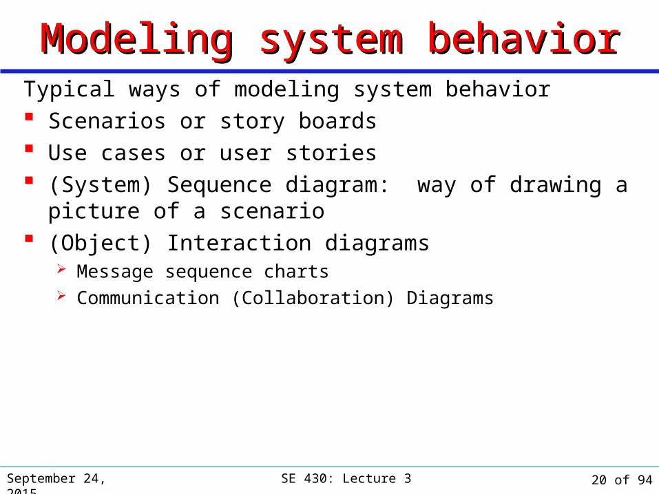
Modeling system behaviorModeling system behaviorTypical ways of modeling system behavior Scenarios or story boards Use cases or user stories (System) Sequence diagram: way of drawing a picture of a
scenario (Object) Interaction diagrams
Message sequence charts Communication (Collaboration) Diagrams
20 of 94

ScenariosScenarios
September 24, 2015 SE 430: Lecture 3
A scenario is a little story it is an outline of some
expected sequence of events
A scenario is used to convey the fundamentals of “how things work”
It usually includes at least one actor
Each actor can make requests of the system or respond to system activity
I would like a book of stamps, please.
That will be $9.90.
Here is $10.
Thanks. Here are your stamps and your change.
Yes.
OK. Will that be all?
21 of 94

September 24, 2015 SE 430: Lecture 3
High-level system viewHigh-level system view If we look at the system as a
“black box”, we can identify some of the external users of the system (either humans or other computer systems) The simplest “black box”
diagram is a system diagram, which shows the outside actors
The use case diagram is more elaborate: it also shows the connections between “use cases” and actors
register
deleteoffering
create newcourse
My systemStudent
Administrator
Instructor
Use case diagram
System diagram
My system
Student
Administrator
Instructor
22 of 94
September 24, 2015 SE 430: Lecture 3
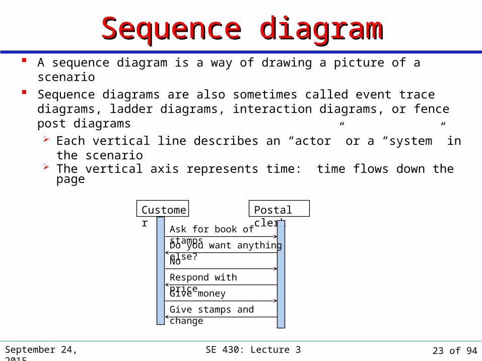
Sequence diagramSequence diagram A sequence diagram is a way of drawing a picture of a scenario Sequence diagrams are also sometimes called event trace diagrams,
ladder diagrams, interaction diagrams, or fence post diagrams Each vertical line describes an “actor” or a “system” in the scenario The vertical axis represents time: time flows down the page
Postal clerk
Ask for book of stamps
Customer
No
Do you want anything else?
Respond with price
Give stamps and change
Give money
23 of 94
September 24, 2015 SE 430: Lecture 3
Iterative DevelopmentIterative DevelopmentUse Cases Decide and describe the functional requirements of the
system Bring agreement between the customer and software
developer Give a clear and consistent description of what the system
should do. Provide a basis for performing tests that verify the system
delivers the functionality stated. Trace the functional requirements into actual classes and
operations in the system.
24 of 94
Use-Case Model IUse-Case Model I
Concepts and Background The Use-Case Model in the Unified Process Use-Case Workflow Use-Case Tasks and Artifacts
September 24, 2015 SE 430: Lecture 3 25 of 94

Concepts and BackgroundConcepts and Background
September 24, 2015 SE 430: Lecture 3 26 of 94

September 24, 2015 SE 430: Lecture 3
Use CasesUse Cases A use case tells a story of actors using a system.
“Rent Videos” A use-case is a sequence of actions a system performs that yields
an observable result of value to a particular actor.
One artifact to express (especially) functional requirements. Emphasizes thinking about the valuable objectives-
oriented viewpoint of the users.
27 of 94

September 24, 2015 SE 430: Lecture 3
What is a use case?What is a use case? Documents a set of interactions between a user (or actor) and a
computer system. Can be viewed as a necessary (but not sufficient) collection of
requirements for those interactions. Use cases:
Help to focus on achieving well-defined user goals. Vary widely in their level of detail.
Capture use cases by: Interviewing users. Discussing their use of the system. Naming (a form of abstraction) and describing each use of system.
Hint: Domain processes and events from the system context description are good sources for use cases. Also functional requirements.
28 of 94
September 24, 2015 SE 430: Lecture 3
Use casesUse cases A use case is a concept that is related to scenarios:
A use case is a description of all the possible sequences of interactions among the system and one or more actors in response to some initial stimulus by one of the actors. (Rumbaugh)
A use case is a collection of possible sequences of interactions between the system under discussion and its external actors, related to a particular goal. (Cockburn)
In a use case, the system is considered as a black box
29 of 94
September 24, 2015 SE 430: Lecture 3
Use casesUse cases Each actor is an external thing that interacts with the
system An actor can represent either a human user or another system Actors have goals; they want to accomplish something
Use cases are often documented by drawing some scenarios Use case analysis often considers both “sunny-day scenarios” and
exceptional cases
30 of 94

September 24, 2015 SE 430: Lecture 3
User goals and system interactionsUser goals and system interactions Recall: User goals are specific,
but not detailed, descriptions of what user wants the system to do
A system interaction occurs when a user attempts to do something to achieve a goal
A single user goal may lead to several system interactions
31 of 94
September 24, 2015 SE 430: Lecture 3
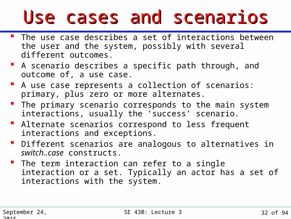
Use cases and scenariosUse cases and scenarios The use case describes a set of interactions between the user and the
system, possibly with several different outcomes. A scenario describes a specific path through, and outcome of, a use
case. A use case represents a collection of scenarios: primary, plus zero or
more alternates. The primary scenario corresponds to the main system interactions,
usually the ‘success’ scenario. Alternate scenarios correspond to less frequent interactions and
exceptions. Different scenarios are analogous to alternatives in switch..case
constructs. The term interaction can refer to a single interaction or a set. Typically
an actor has a set of interactions with the system.
32 of 94

September 24, 2015 SE 430: Lecture 3
From user goals to scenariosFrom user goals to scenarios
Goal/requirement space System behavior space
33 of 94

September 24, 2015 SE 430: Lecture 3
Another viewAnother view
User Goal
Interaction 1 Interaction 2 Interaction n
…
Use case 2
Scenario 1 Scenario 2
…
Scenario n
yields
maps to
composed of
… …
34 of 94
September 24, 2015 SE 430: Lecture 3
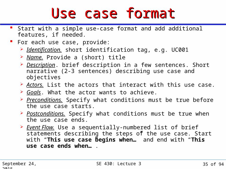
Use case formatUse case format Start with a simple use-case format and add additional features, if
needed. For each use case, provide:
Identification. short identification tag, e.g. UC001 Name. Provide a (short) title Description. brief description in a few sentences. Short narrative (2-
3 sentences) describing use case and objectives Actors. List the actors that interact with this use case. Goals. What the actor wants to achieve. Preconditions. Specify what conditions must be true before the use
case starts. Postconditions. Specify what conditions must be true when the use
case ends. Event Flow. Use a sequentially-numbered list of brief statements
describing the steps of the use case. Start with “This use case begins when…” and end with “This use case ends when…”.
35 of 94

September 24, 2015 SE 430: Lecture 3
High-level use case: primary scenarioHigh-level use case: primary scenarioIdentification: UC003Name: Artifact physical care requirements entryDescription: Enter physical care requirements for a new artifact into the Artifact
Tracking System (ATS)Actors: Artifact Tracking (AT) staff member (user); climate, fire, and security
control subsystemsTrigger: AT staff member wishes to enter all the climate, fire, and security control
physical care requirements for a new artifact into the ATSGoals: see Trigger abovePreconditions:
Ø AT staff member must be logged into the ATS.Ø AT staff member must have entered the unique identification code
assigned to the artifact.Incoming information: Climate, fire control, and security requirements for artifactResults: Artifact physical care requirements are entered into ATSPostconditions:
Ø ATS (in collaboration with appropriate subsystems) confirms Museum can provide appropriate physical care for artifact.
36 of 94
September 24, 2015 SE 430: Lecture 3
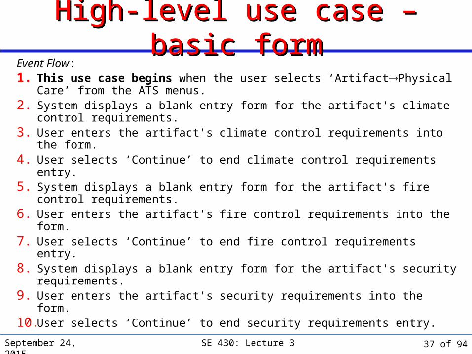
High-level use case – basic formHigh-level use case – basic formEvent Flow:1. This use case begins when the user selects ‘ArtifactPhysical Care’
from the ATS menus.2. System displays a blank entry form for the artifact's climate control
requirements.3. User enters the artifact's climate control requirements into the form.4. User selects ‘Continue’ to end climate control requirements entry.5. System displays a blank entry form for the artifact's fire control
requirements.6. User enters the artifact's fire control requirements into the form.7. User selects ‘Continue’ to end fire control requirements entry.8. System displays a blank entry form for the artifact's security
requirements.9. User enters the artifact's security requirements into the form.10. User selects ‘Continue’ to end security requirements entry.
37 of 94
September 24, 2015 SE 430: Lecture 3
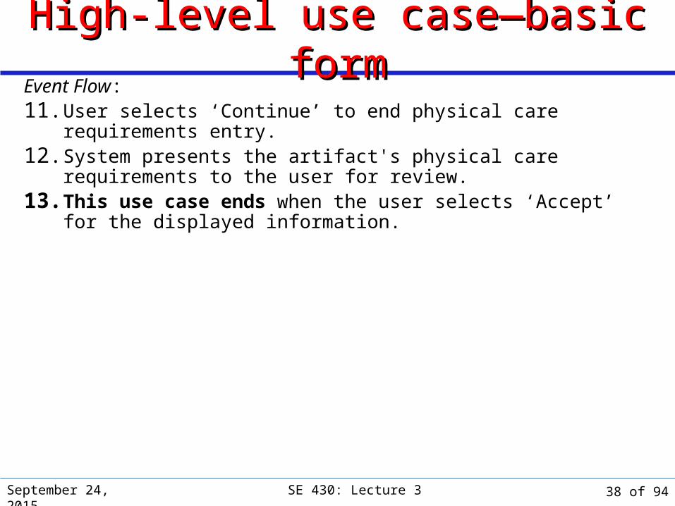
High-level use case—basic formHigh-level use case—basic formEvent Flow:11. User selects ‘Continue’ to end physical care requirements entry.12. System presents the artifact's physical care requirements to the user
for review.13. This use case ends when the user selects ‘Accept’ for the displayed
information.
38 of 94
September 24, 2015 SE 430: Lecture 3
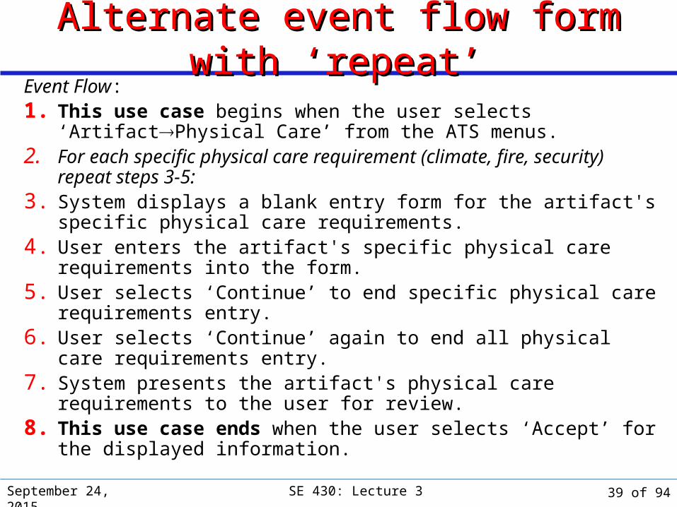
Alternate event flow form with Alternate event flow form with ‘‘repeatrepeat’’ Event Flow:1. This use case begins when the user selects ‘ArtifactPhysical Care’
from the ATS menus.2. For each specific physical care requirement (climate, fire, security)
repeat steps 3-5:3. System displays a blank entry form for the artifact's specific physical
care requirements.4. User enters the artifact's specific physical care requirements into the
form.5. User selects ‘Continue’ to end specific physical care requirements entry.6. User selects ‘Continue’ again to end all physical care requirements
entry.7. System presents the artifact's physical care requirements to the user for
review.8. This use case ends when the user selects ‘Accept’ for the displayed
information.
39 of 94
September 24, 2015 SE 430: Lecture 3
Use case evolutionUse case evolution Storyboards represent an early form of use case. Use cases were formalized in Ivar Jacobson's Objectory process
and later popularized in Object-Oriented Software Engineering: A Use Case Driven Approach (1992).
Use cases were incorporated in UML at the very earliest stages: sometime around v. 0.9 or 1.0.
Use cases have been part of the Unified Process – “a use-case-driven process” – from its inception.
Schneider & Winters (Applying Use Cases: A Practical Guide), Cockburn (Writing Effective Use Cases), and others have helped make use cases more accessible.
40 of 94

September 24, 2015 SE 430: Lecture 3
Use cases in the software life cycleUse cases in the software life cycle First iteration of Elaboration:
About 80% of use cases captured.
About 10% detailed.
Why just 10%? About 10% of project use cases will be identified as highest-risk.
Subsequent iterations: Most use cases captured.
About 80% detailed by end.
Why only 80%? About 20% of use cases will be minor variations on others or will be trivial.
Construction: Use cases added or extended by recycling to Inception phase.
41 of 94
Use Case WorkflowUse Case Workflow
September 24, 2015 SE 430: Lecture 3 42 of 94
September 24, 2015 SE 430: Lecture 3
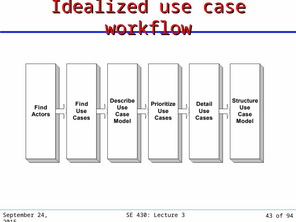
Idealized use case workflowIdealized use case workflow
43 of 94
September 24, 2015 SE 430: Lecture 3
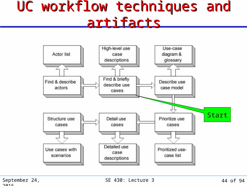
UC workflow techniques and artifactsUC workflow techniques and artifacts
Start
44 of 94
Use Case Tasks & ArtifactsUse Case Tasks & Artifacts
September 24, 2015 SE 430: Lecture 3 45 of 94
September 24, 2015 SE 430: Lecture 3
Find actorsFind actors Identifying actors is the most critical element in constructing
the use-case model. A use-case actor interacts with the system in a specific role Candidate actors can come from several sources. System context description can be a rich source of
candidate actors. Actors may take on more than one role, depending upon
specific interaction.
46 of 94

September 24, 2015 SE 430: Lecture 3
Find actorsFind actors Minimize overlap of roles that different use-case actors play:
Combine overlapping roles into a single role for one actor» Example: Assign ‘Security Profile Administrator’ role and ‘Access
Privileges Manager’ roles to a single Security Profile Manager actor, unless there is a good reason to keep them separate
Assign one or more overlapping roles to separate actors.» Example: A Museum Administrator may act in both system
management and end user roles. Assign these very different roles to two different actors: System Manager and End User
47 of 94

September 24, 2015 SE 430: Lecture 3
Types of actors Types of actors Primary actors
The source of user goals. Have goals satisfied through interactions with the system. Example: ATS staff member has goals satisfied by ATS.
Supporting actors Provide a service to the system. Have interfacing requirements with the system. Example: Climate, security, and fire control systems are supporting
actors to the ATS, providing ATS with information. Offstage actors
Have secondary (or more-removed) interaction with the system. May have needs that the system satisfies. Example: Visitor Information system is an off-stage actor to the
ATS. ATS provides information to Visitor Information system.
48 of 94
September 24, 2015 SE 430: Lecture 3
Find use casesFind use cases There is no cookbook formula for finding use cases. Good starting points for finding use cases:
Interviews with users. Domain processes and events from system context description. Interactions associated with various type of actors. Functional Requirements. Any other requirements.
49 of 94
September 24, 2015 SE 430: Lecture 3
Exercise: Identifying use casesExercise: Identifying use cases Suppose we want to develop an Automated Teller Machine.
List some of the use cases for such a system:
50 of 94

September 24, 2015 SE 430: Lecture 3
Exercise: Identifying use casesExercise: Identifying use cases Suppose we want to develop an Automated Teller Machine.
List some of the use cases for such a system: Get instant cash Transfer money Get money from checking Balance check Deposit cash or checks
51 of 94
September 24, 2015 SE 430: Lecture 3
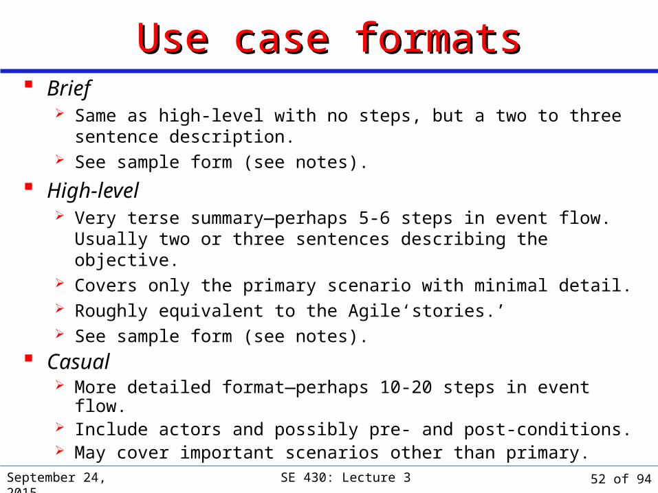
Use case formatsUse case formats Brief
Same as high-level with no steps, but a two to three sentence description.
See sample form (see notes).
High-level Very terse summary—perhaps 5-6 steps in event flow. Usually two
or three sentences describing the objective. Covers only the primary scenario with minimal detail. Roughly equivalent to the Agile‘stories.’ See sample form (see notes).
Casual More detailed format—perhaps 10-20 steps in event flow. Include actors and possibly pre- and post-conditions. May cover important scenarios other than primary.
52 of 94
September 24, 2015 SE 430: Lecture 3
Use case formatsUse case formats Fully-dressed (detailed) or expanded or extended
Lengthy and detailed—perhaps > 15-20 steps in event flow. Covers most scenarios. Can be trimmed to suit phase and priority of use case.
Or, see my sample forms:http://condor.depaul.edu/dmumaugh/readings/SE430readings.html[Project Forms and Documents]
53 of 94

September 24, 2015 SE 430: Lecture 3
Variations on a ThemeVariations on a Theme Many different use case formats. Cockburn had over 37
variations. Use whatever provides the most information at the level of
detail appropriate The reading list has a couple of forms that might be useful.
54 of 94

September 24, 2015 SE 430: Lecture 3
Describing the Use-case Model As a WholeDescribing the Use-case Model As a Whole
We need some way to summarize and track the various actors and use cases and their relationships
Full use-case model consists of:1. Use-case (prose) descriptions, at various appropriate levels of
detail
2. Glossary which contains definitions and descriptions of items in the use-case model
3. Visual model in the form of a use-case diagram
4. Select system sequence diagrams
55 of 94
GlossaryGlossaryA glossary is part of the use-case model Consists of all the terms and phrases listed in the
requirements document List of actors and their goals List of use-cases (name and description) Any new terms and phrases introduced
September 24, 2015 SE 430: Lecture 3 56 of 94

September 24, 2015 SE 430: Lecture 3
Use-case diagramUse-case diagram Static, summary illustration of
use-case structure. Stick-people icons are actors
that use the system, linked to particular use case(s).
Rectangles represent external system actors that interact with the use case.
Ellipses indicate use cases themselves.
«extends» link » specialization «uses» link » aggregation «include» is same as «uses»
57 of 94

September 24, 2015 SE 430: Lecture 3
ATS sample use-case diagramATS sample use-case diagram
Save and publishnew artifactdescription
Create newartifact
description
Enter artifactphysical carerequirements
Enter artifactphysical
description
ATS StaffMember
<< actor>>
Climate Control
Subsystem
<< actor>>
Fire ControlSubsystem
<< actor >>
Security ControlSubsystem
58 of 94

September 24, 2015 SE 430: Lecture 3
Sidebar: Identifying the system boundarySidebar: Identifying the system boundary
Like most analysis and design concepts, system and system boundary may vary with the level of abstraction.
The system represents the software and hardware elements which are the current focus of attention. Example: In the Museum Automation Problem, each individual
subsystem—climate, security, Visitor Information—can be considered ‘the system’ during its analysis and design.
The system boundary represents the division between the system itself, including software and hardware, and the actors: primary, supporting, and off-stage.
Defining the scope of the system during the requirements effort can help delineate the system boundary.
59 of 94
September 24, 2015 SE 430: Lecture 3
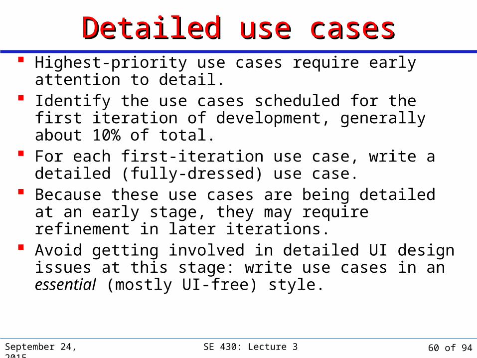
Detailed use casesDetailed use cases Highest-priority use cases require early attention to detail. Identify the use cases scheduled for the first iteration of
development, generally about 10% of total. For each first-iteration use case, write a detailed (fully-
dressed) use case. Because these use cases are being detailed at an early
stage, they may require refinement in later iterations. Avoid getting involved in detailed UI design issues at this
stage: write use cases in an essential (mostly UI-free) style.
60 of 94
September 24, 2015 SE 430: Lecture 3
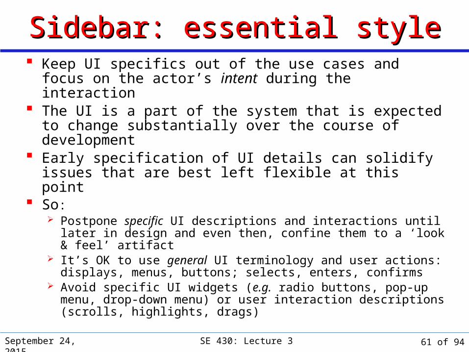
Sidebar: essential styleSidebar: essential style Keep UI specifics out of the use cases and focus on the
actor’s intent during the interaction The UI is a part of the system that is expected to change
substantially over the course of development Early specification of UI details can solidify issues that are
best left flexible at this point So:
Postpone specific UI descriptions and interactions until later in design and even then, confine them to a ‘look & feel’ artifact
It’s OK to use general UI terminology and user actions: displays, menus, buttons; selects, enters, confirms
Avoid specific UI widgets (e.g. radio buttons, pop-up menu, drop-down menu) or user interaction descriptions (scrolls, highlights, drags)
61 of 94
September 24, 2015 SE 430: Lecture 3
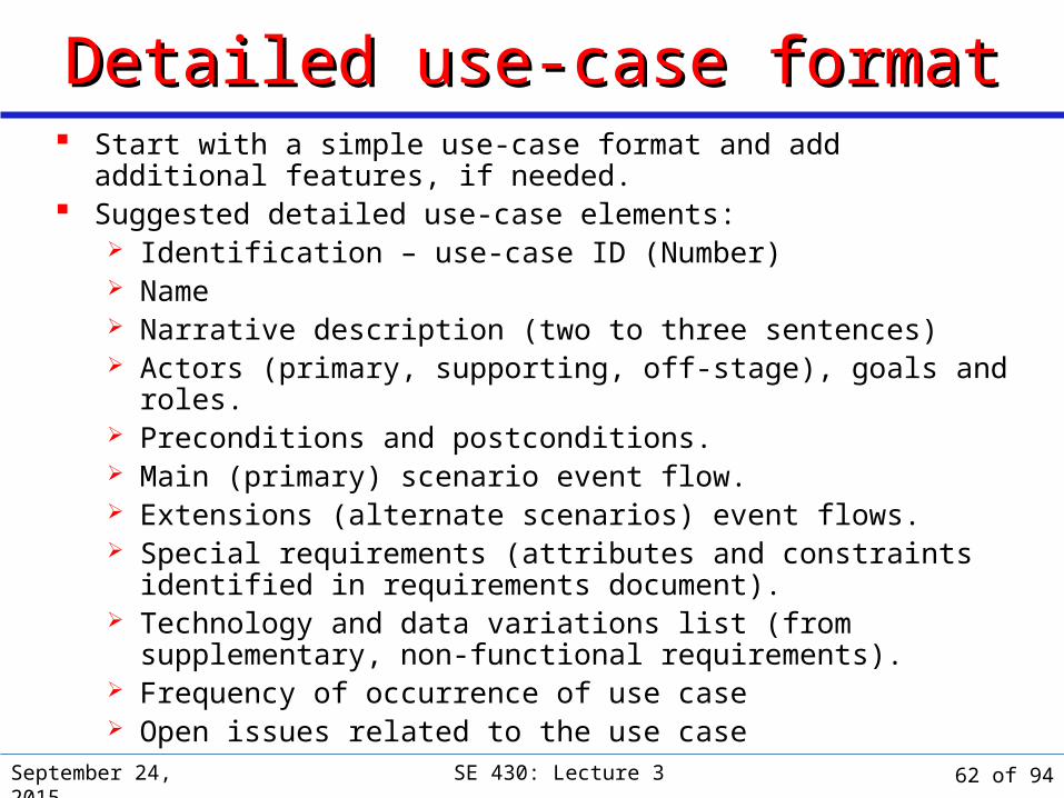
Detailed use-case formatDetailed use-case format Start with a simple use-case format and add additional features, if
needed. Suggested detailed use-case elements:
Identification – use-case ID (Number) Name Narrative description (two to three sentences) Actors (primary, supporting, off-stage), goals and roles. Preconditions and postconditions. Main (primary) scenario event flow. Extensions (alternate scenarios) event flows. Special requirements (attributes and constraints identified in
requirements document). Technology and data variations list (from supplementary, non-
functional requirements). Frequency of occurrence of use case Open issues related to the use case
62 of 94

September 24, 2015 SE 430: Lecture 3
Structuring the use-caseStructuring the use-case Follow a consistent structure for all detailed use cases. Always use “This use case begins when…” and “This use case ends
when…” stylistic ‘bookends’. The primary scenario should be the one most readily traced through
the use case. Defer exceptional conditions and branches to alternative scenarios. Alternative scenarios (a.k.a. extensions) should follow the primary
scenario in the text. Alternative scenarios are identified by the step number in the primary
scenario plus a letter. Example: Three alternative scenarios that begin at step 6 in a
primary scenario would be labeled 6a, 6b, and 6c.
63 of 94

September 24, 2015 SE 430: Lecture 3
Detailed use case example: headerDetailed use case example: headerIdentification: UC003Name: Artifact physical care requirements entryDescription: Enter physical care requirements for a new artifact into the Artifact
Tracking System (ATS)Actors: Artifact Tracking (AT) staff member (user); climate, fire, and security
control subsystemsTrigger: AT staff member wishes to enter all the climate, fire, and security control
physical care requirements for a new artifact into the ATSGoals: see Trigger abovePreconditions:
Ø AT staff member must be logged into the ATS.Ø AT staff member must have entered the unique identification code
assigned to the artifact.Incoming information: Climate, fire control, and security requirements for artifactResults: Artifact physical care requirements are entered into ATSPostconditions:
Ø ATS (in collaboration with appropriate subsystems) confirms Museum can provide appropriate physical care for artifact.
64 of 94
September 24, 2015 SE 430: Lecture 3
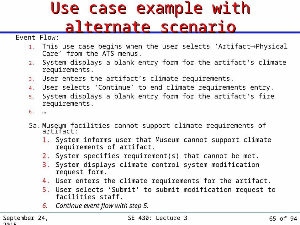
Use case example with alternate scenarioUse case example with alternate scenarioEvent Flow:
1. This use case begins when the user selects ‘ArtifactPhysical Care’ from the ATS menus.
2. System displays a blank entry form for the artifact's climate requirements.3. User enters the artifact’s climate requirements.4. User selects ‘Continue’ to end climate requirements entry.5. System displays a blank entry form for the artifact's fire requirements.6. …
5a. Museum facilities cannot support climate requirements of artifact:1. System informs user that Museum cannot support climate
requirements of artifact.2. System specifies requirement(s) that cannot be met.3. System displays climate control system modification request form.4. User enters the climate requirements for the artifact.5. User selects ‘Submit’ to submit modification request to facilities staff.6. Continue event flow with step 5.
65 of 94
September 24, 2015 SE 430: Lecture 3
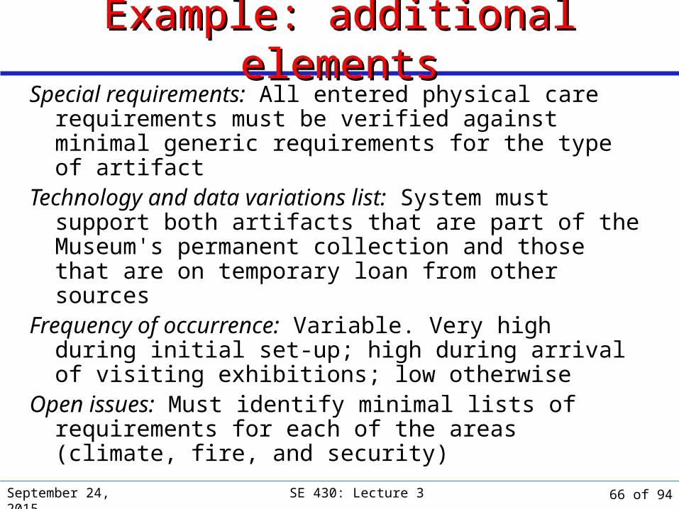
Example: additional elementsExample: additional elementsSpecial requirements: All entered physical care requirements
must be verified against minimal generic requirements for the type of artifact
Technology and data variations list: System must support both artifacts that are part of the Museum's permanent collection and those that are on temporary loan from other sources
Frequency of occurrence: Variable. Very high during initial set-up; high during arrival of visiting exhibitions; low otherwise
Open issues: Must identify minimal lists of requirements for each of the areas (climate, fire, and security)
66 of 94
September 24, 2015 SE 430: Lecture 3
Prioritize use casesPrioritize use cases Planning in an iterative and incremental process is risk-
driven. Schedule analysis, design, and implementation of use
cases representing core system (required vs. desirable or optional) functionality and high-risk use cases for early iterations
Conversely, schedule development of non-core-functionality and low-risk use cases for later iterations.
Need to balance risk and functionality factors. At this stage, consider priority based on:
Proportion of contribution to overall system functionality. Technological, skills, and dependency risks.
67 of 94

September 24, 2015 SE 430: Lecture 3
Risk factorsRisk factors Requirements risks
Have you properly identified requirements for system? Have you reviewed project scope? Can you effectively set functional requirements priorities?
Technological risks Are you using a new, untested technology?
Dependency risks Are you depending on a third-party product?
Skills risks Are you planning to do something with which you are completely
unfamiliar? Do you have the right staff with the necessary skills?
68 of 94
September 24, 2015 SE 430: Lecture 3
Ranking (or Prioritizing) Use CasesRanking (or Prioritizing) Use CasesProject managers use use case versions for development
cycles Time-box development cycles have a fixed time frame. Complex use cases may require multiple development
cycles to be fully implemented. Create simplified versions of the complex use case that
can be developed within each subsequent time-box.
69 of 94
September 24, 2015 SE 430: Lecture 3
Ranking Use CasesRanking Use CasesSetting Priorities – Rank Order use cases Many factors may be need to be considered when ranking
or prioritizing use cases:A. Impact on the architectural design
B. Information and insight regarding the design
C. Risky, time-critical, or complex functions
D. New or risky technology.
E. Represent line-of-business processes
F. Directly support increased revenue or decreased costs.
70 of 94

September 24, 2015 SE 430: Lecture 3
Ranking Use CasesRanking Use Cases
Use Case A B C D E F Sum
Buy Items 5 3 2 0 5 3 18
Add New Users 3 3 2 0 2 2 12
Start Up 3 2 2 0 2 2 11
71 of 94

September 24, 2015 SE 430: Lecture 3
Rank Use Case Justification
High Buy Items Scores on most increased ranking criteria
Medium Add New UsersLog InRefund Items
Affects Security DomainAffects Security DomainImportant process affects Accounting
Low Cash OutStart UpShut Down
Minimal effect on architectureDefinition is dependent on other use casesMinimal effect on architecture
Ranking Use CasesRanking Use CasesIt is also possible to do simpler classifications – high, medium,
low
72 of 94
September 24, 2015 SE 430: Lecture 3
Practical tipsPractical tips Pick a set of use cases that maximizes system coverage
write two or three of the most common simple transactions first; most common or “sunny day”
it is easy to get carried away generating too many use cases, so try to create more “abstract” scenarios when three or more scenarios look very similar
Keep a list of Actors/Roles/Goals/Use Cases After all use cases are developed, refactor for common
elements
73 of 94
September 24, 2015 SE 430: Lecture 3
Practical tipsPractical tips Beware of analysis paralysis
inability to write any scenarios, or creating too many detailed scenarios
Techniques to get out of analysis paralysis: write two or three of the most common simple transactions first it is easy to get carried away generating too many use cases, so
try to create more “abstract” scenarios when three or more scenarios look very similar
be cautious of generating more than 30 use cases to cover the fundamental system actions
additional use cases for unusual events should be chosen with care and kept to a manageable number
74 of 94
September 24, 2015 SE 430: Lecture 3
ConceptsConcepts In writing use cases, start to identify potential classes,
objects, and sub-systems Use cases are used to generate the conceptual (domain)
model Nouns become “concepts” or classes/objects Verbs become “actions” or methods
Start each use case name with a verb. Start sentence 1 with “<Actor> does <event>” All systems have a Start Up and Shut Down use case
(perhaps trivial).
75 of 94

September 24, 2015 SE 430: Lecture 3
System testingSystem testing One big reason for writing use cases: they really help
when it is time to test the entire system both sunny day cases and exception behavior can be extracted
from the use case descriptions the use cases define what behavior is inside the system and what
behavior depends on the external actors
Since use cases treat the system as a black box, there is a great deal of design freedom, but the external behavior must be correct
76 of 94

September 24, 2015 SE 430: Lecture 3
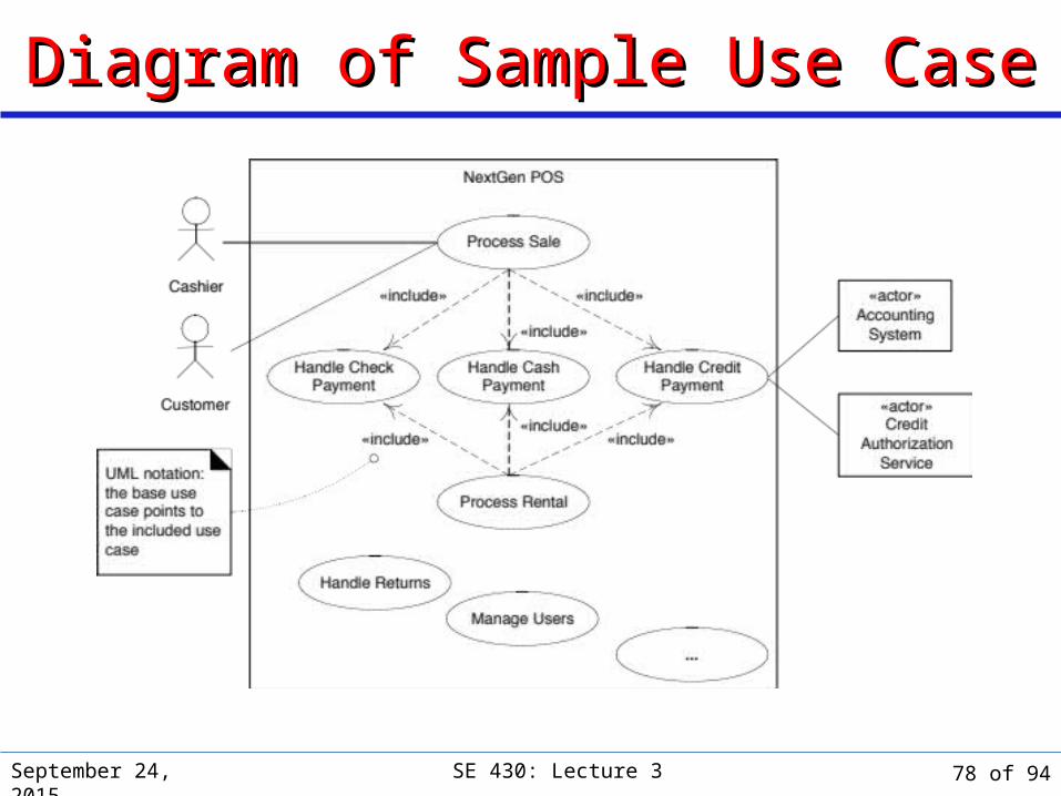
Use Case DiagramUse Case Diagram A way to conceive and
illustrate the use cases. Usually created during the
initial use case analysis.
77 of 94
September 24, 2015 SE 430: Lecture 3
Diagram of Sample Use CaseDiagram of Sample Use Case
78 of 94

Use-Case Model IIUse-Case Model II
Use case workflow tasks and artifacts
System Sequence Diagrams
September 24, 2015 SE 430: Lecture 3 79 of 94
September 24, 2015 SE 430: Lecture 3
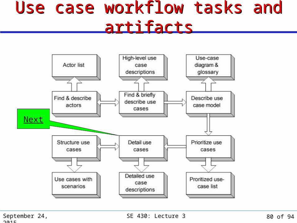
Use case workflow tasks and artifactsUse case workflow tasks and artifacts
Next
80 of 94

September 24, 2015 SE 430: Lecture 3
Statecharts discussed in
context of object
behavior.
Additional techniques and artifactsAdditional techniques and artifacts
Next
81 of 94

System Sequence DiagramsSystem Sequence Diagrams
September 24, 2015 SE 430: Lecture 3 82 of 94
September 24, 2015 SE 430: Lecture 3
Use Cases and System Sequence DiagramsUse Cases and System Sequence Diagrams
A use case is a prose description of an actor/system interaction.
Use case diagram is a visual summary of: All significant use cases. All significant actors. Relations among actors and use cases.
A System sequence diagram (SSD) is a visual summary of the individual use cases.
For ease of understanding, each use-case scenario corresponds to a separate system sequence diagram.
83 of 94
September 24, 2015 SE 430: Lecture 3
Characteristics of System Sequence DiagramsCharacteristics of System Sequence Diagrams
System sequence diagrams are a special case of the more-general UML sequence diagram.
Captures the sequencing of messages and data exchanged between an actor and the system.
Provides about the same level of detail as use-case prose description.
Usually deals with primary actors and system, but can include other actors as well.
Provides a more formal notation for expressing the interaction.
Concerned only with external behavior: the system is treated as a black box.
84 of 94

September 24, 2015 SE 430: Lecture 3
System Sequence DiagramSystem Sequence Diagram
85 of 94

September 24, 2015 SE 430: Lecture 3
System Sequence Diagram NotationSystem Sequence Diagram Notation
.
Note that software participants cannot
perform operations on human actors!
86 of 94
September 24, 2015 SE 430: Lecture 3
Sequence DiagramsSequence Diagrams
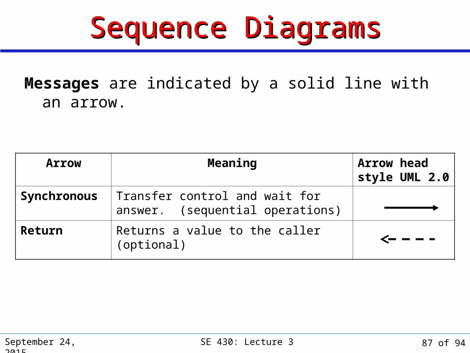
Messages are indicated by a solid line with an arrow.
Arrow Meaning Arrow head style UML 2.0
Synchronous Transfer control and wait for answer. (sequential operations)
Return Returns a value to the caller (optional)
87 of 94
September 24, 2015 SE 430: Lecture 3
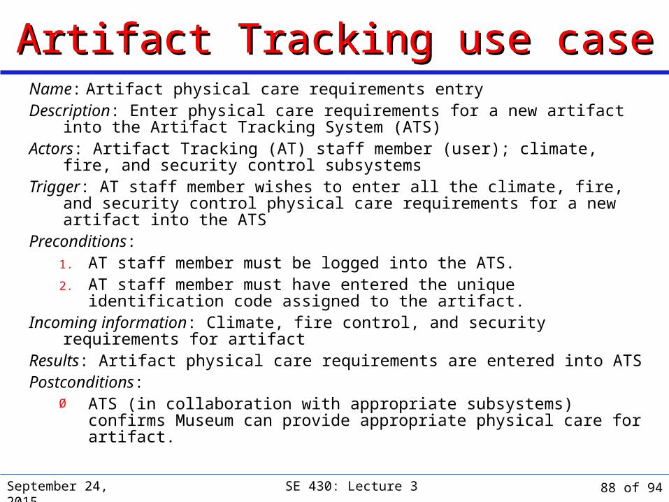
Artifact Tracking use caseArtifact Tracking use caseName: Artifact physical care requirements entryDescription: Enter physical care requirements for a new artifact into the
Artifact Tracking System (ATS)Actors: Artifact Tracking (AT) staff member (user); climate, fire, and
security control subsystemsTrigger: AT staff member wishes to enter all the climate, fire, and security
control physical care requirements for a new artifact into the ATSPreconditions:
1. AT staff member must be logged into the ATS.2. AT staff member must have entered the unique identification code
assigned to the artifact.Incoming information: Climate, fire control, and security requirements for
artifactResults: Artifact physical care requirements are entered into ATSPostconditions:
Ø ATS (in collaboration with appropriate subsystems) confirms Museum can provide appropriate physical care for artifact.
88 of 94
September 24, 2015 SE 430: Lecture 3
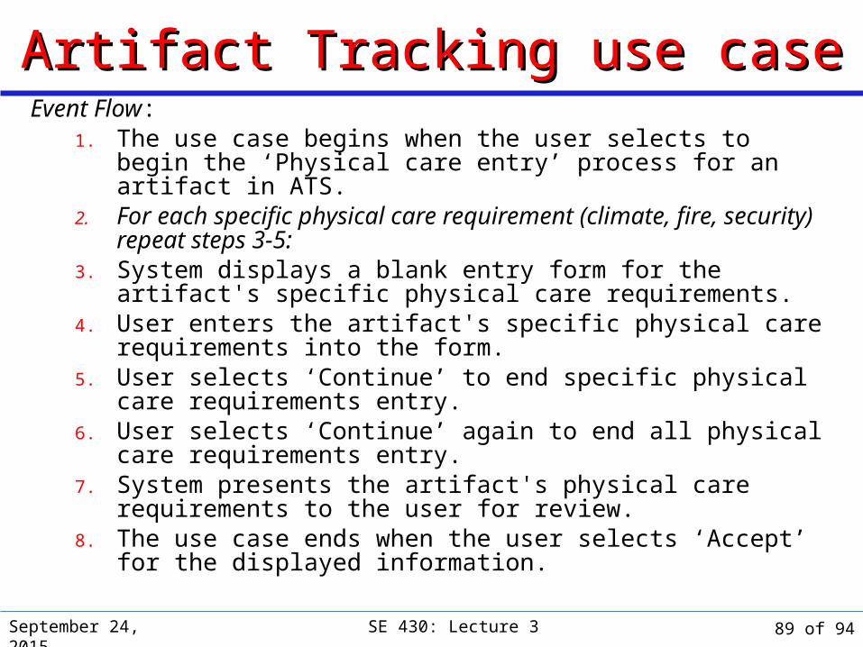
Artifact Tracking use caseArtifact Tracking use caseEvent Flow:
1. The use case begins when the user selects to begin the ‘Physical care entry’ process for an artifact in ATS.
2. For each specific physical care requirement (climate, fire, security) repeat steps 3-5:
3. System displays a blank entry form for the artifact's specific physical care requirements.
4. User enters the artifact's specific physical care requirements into the form.
5. User selects ‘Continue’ to end specific physical care requirements entry.
6. User selects ‘Continue’ again to end all physical care requirements entry.
7. System presents the artifact's physical care requirements to the user for review.
8. The use case ends when the user selects ‘Accept’ for the displayed information.
89 of 94
September 24, 2015 SE 430: Lecture 3
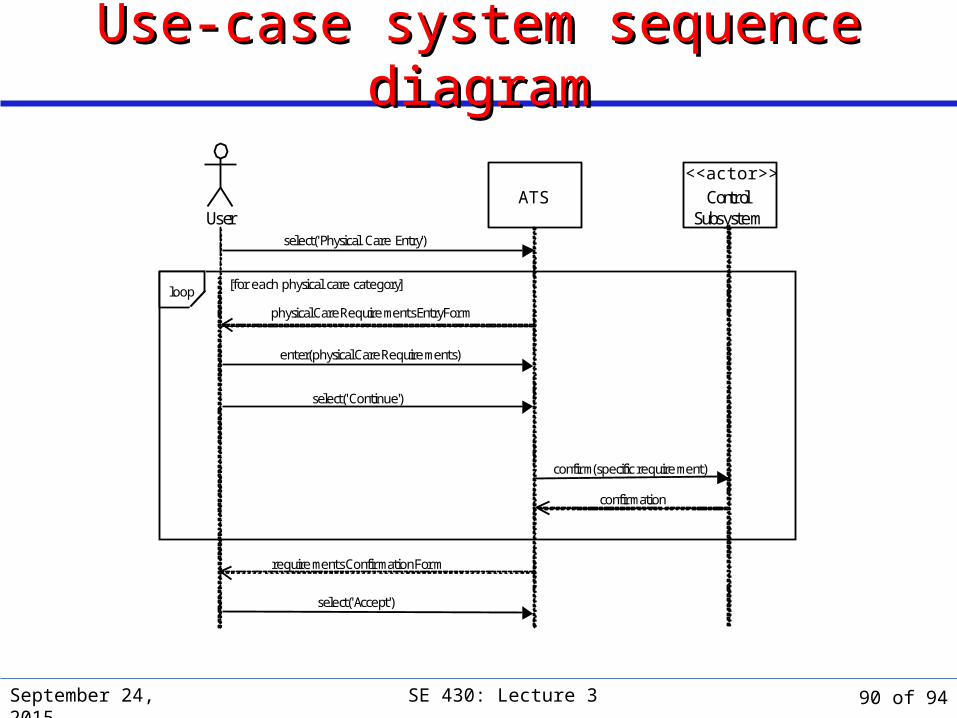
Use-case system sequence diagramUse-case system sequence diagram
ATS
select('Physical Care Entry')
User
select('Continue')
physicalCareRequirementsEntryForm
enter(physicalCareRequirements)
<<actor>>Control
Subsystem
confirm(specific requirement)
requirementsConfirmationForm
select('Accept')
confirmation
[for each physical care category]loop
90 of 94

September 24, 2015 SE 430: Lecture 3
SSD – With Use CaseSSD – With Use Case
91 of 94
September 24, 2015 SE 430: Lecture 3
SummarySummary OO analysis starts with the following “requirements-oriented
” data: problem statement list of text inputs set of use cases
A Use-case is a major distinct, complete, end-to-end process of using a system. Not usually one step, but a complete story.
Use cases tell a story of actors using a system. Examples
» Rent Videos» Return Videos» Pay Fines
A use-case is a sequence of actions a system performs that yields an observable result of value to a particular actor.
92 of 94

September 24, 2015 SE 430: Lecture 3
SummarySummary A use-case is one artifact to express (especially) functional
requirements. Use-cases emphasize thinking about the valuable, objectives-oriented
viewpoint of the users. They illustrate functional requirements, by the stories they tell. Use-cases are valuable for:
providing a good overview of the system to be developed defining the system boundary helping to generate the test suites
Complementary with a feature requirement list. Choose use-cases carefully since they are the requirements for the
entire system and the foundation for the OO analysis process Forms a contract (see Design by Contract)
93 of 94

Next ClassNext ClassTopic:
Static Structure: Requirements Traceability; Building a Beginning Conceptual Model: Class Diagram; CRC Cards; Domain model basic principles; Domain model associations; Domain model attributes; System Glossary.
Reading:
Arlow & Neustadt: Ch’s 6-9 Driving Design: The Problem Domain Tracing Your Design
Using CRC CardsAssignment – October 1, 2015
September 24, 2015 SE 430: Lecture 3 94 of 94