sc/st multimode & singlemode connector termination ... cap from the lightspeed® adhesive...
TRANSCRIPT

Important!!To avoid possible fiber breakage,
do not insert the fiber so far that it con-tacts the bottom of the primer bottle!! Theprimer bottle label indicates the minimumusable depth.Note: Cap the bottle when not in use to avoidcontamination. Store both primer and adhesivebetween 40° F (4.4° C) and 100° F (38° C).
8
SC/ST Multimode & Singlemode Connector Termination Instructions
Put on safety glasses and preparethe work area for termination.This involves removing and
organizing all the necessary tools from theFiber Termination Kit (P/N: FTERM-L2), andthe Consumables Kit (P/N: FT-CKIT-L2).
Note: To utilize the Alcohol Dispenser, fill it with99% reagent grade isopropyl alcohol (notincluded).
A
Remove cap from theLightSpeed® adhesive syringe by
unthreading it. *Install the metal syringetip provided by threading it onto cartridgeuntil it locks.
Note: Save the syringe cap to enable re-cappingwhen a partially used syringe is returned to thecase for later use.
*Tip: Use the nose of the jacket stripper forunthreading syringe caps.
1Slide the strain relief boot (andcrimp sleeve for jacketed fiber)
over the fiber in the proper orientation asshown.Note: One end of the SC crimp sleeve isstepped-down. Orient the crimp sleeve suchthat the smaller end is installed onto the cablefirst. One end of the ST crimp sleeve is flaredout. Install the un-flared end onto the cablefirst.
2
Using the buffer strippers, strip offthe buffer in at least two pieces.
Note 1: Attempting to strip the entire length ofbuffer in one swipe will typically result in breakage. Note 2: Be sure the tool blade area is free ofbuffer debris.
5
Using the marker pen andtemplate card provided, measure
and mark the buffer strip length asshown on the template.
4
Using a dry, lint-free wipe,remove any remnants of the
protective coating on the fiber afterstripping the buffer.
Note: It is important to ensure that all remnants ofthe coating are removed or the fiber will not fit intothe connector.DO NOT touch fiber after cleaning.
6
Buffered Fiber Termination
Jacketed Fiber Termination
Insert primer bottle into thestand. Dip the entire exposed
fiber into the LightSpeed® primer andplace in a protected area to avoiddamage.Note: It is important that the entire exposedfiber be coated with the primer includingsome portion of the buffer coating. Forjacketed terminations, do not be concernedwith keeping the kevlar strands out of theprimer solution.
7
Minimum usable depthline
COMPONENTS:
A. Duplex Clip (SC only)B. Connector Housing (SC only)C. Connector bodyD. Crimp SleeveE. Strain Relief BootNote: Enhanced SC connectors shownthroughout except where indicated.
B
A B C
D EC
D
E
E
Expiration Datemm/dd/yy
ExpirationDate
mm/dd/yy
Jacket Removal:For Jacketed Terminations:Using the jacket stripper tool,
strip off the outer jacket at the ‘A’ lengthindicated on the template card. Use the1.6mm opening for 3.0mm fiber. Alsotrim the Kevlar to the ‘C’ length using theelectrician style scissors.For Buffered Only Terminations:Follow recommended cable slackguidelines to determine amount of jacketremoval if applicable.
3

#2 Film (Pink):Place the polishing pad onto a flat
surface with the rubber side facing up.Place the #2 film onto the polishing padwith the glossy side of film down. Note: Prior to polishing, clean pad surface withalcohol soaked wipe to provide for a smoothpolishing surface. This will also allow thepolishing paper to stick in place. (Ensure no air istrapped between pad and film). Also clean surfaceof polishing puck.
19
Jacketed Fiber Only, SC Connector
Slide the crimp sleeve up over the kevlarso that it is seated against the shoulderof the connector housing, being sure thatit does not move prior to being crimped.Position the crimp tool at the end of thecrimp sleeve (large end) using the largeror 0.19 inch opening in the crimp die.Crimp the sleeve by closing the crimptool completely and releasing.
13Jacketed Fiber Only, SC Connector
A second crimp is required to secure thejacket. Crimp this time onto the stepped-down portion of the crimp sleeve usingthe smaller or 0.137 inch opening in thecrimp die.
14
Remove the excess fiber with astraight, non-twisting pull and
deposit in a safe place (i.e. onto a piece oftape or in the debris container).Note 1: If fiber does not readily pull off, repeatprevious step – scoring on opposite side of fiber.Note 2: Fiber pieces are difficult to see. If notproperly disposed, glass fibers may cause seriousinjury.Note 3: Be careful not to bump or brush end-facebefore polishing.
12
Slide the boot up into place ontothe crimp sleeve (jacketed fiber)
or connector housing barrel (bufferedfiber).
17#1 Film (Gray):“Air polish” by holding the connectorin one hand and the film in the other.
Gently brush the dull side of the polishing filmin a “figure 8” fashion with the ferrule tip towear the small fiber protrusion into a smoother,more polishable tip. Continue until the tip isalmost flush with the ferrule.Note: If using Siemon’s Automated Fiber Polisher(p/n: FPOL), refer to polishing instructions includedwith that unit. The FPOL is for use in multimodeapplications only.
18
Jacketed Fiber Only, ST Connector
A second crimp is required to secure thejacket. Crimp onto the rear portion of thecrimp sleeve (approximately 4mm [0.16 in.])using the same (0.137 in.) opening in thecrimp die.
16
0.137 Die (1st crimp)
4mm (0.16 in.) max
Remove dust cap from theconnector and insert the adhesive
syringe tip into connector housing until itseats firmly inside. Inject the LightSpeed®
adhesive until a small dot of the adhesiveappears at the ferrule tip. Also inject asmall amount of adhesive into the back endof the connector. This ensures bonding ofthe buffer to the connector, strengtheningthe termination. Be careful not to overfill toprevent a backflow of adhesive.
9Insert the fiber into the connectoruntil the buffer bottoms out inside
the housing. Allow at least 30 seconds curetime before proceeding. Tip: Rotate theconnector during insertion to assist inguiding the fiber into the ferrule. Forjacketed fiber, allow the kevlar to fan outaround the connector barrel.Note: Once primer coated fiber touches theadhesive it will start curing instantly. Fiberinsertion will become increasingly more difficultif not fully inserted within 10 to 15 seconds.
10Hold the flat surface of the fiberscribe tool flat against the ferrule
tip with the beveled edge facing up.Carefully score the fiber close to the inter-section of the ferrule tip and fiber. Score onone side of fiber only.Note: Do not use excessive pressure whenscoring to prevent fiber breakage anduneven fractures. If breakage occurs, keeptrack of fiber piece (see note 2 in next step).Clean the adhesive off blade.
11
SC/ST Multimode & Singlemode ConnectorTermination Instructions
Jacketed Fiber Only, ST Connector
Slide the crimp sleeve up over the kevlarso that it is seated against the shoulderof the connector housing, being sure thatit does not move prior to being crimped.Position the crimp tool at the end of thecrimp sleeve (flared end). Crimp thesleeve using the 0.137 in. opening byclosing the crimp tool completely andreleasing.
15
0.137 Die (2nd crimp)0.19 Die (1st crimp)
0.137 Die (2nd crimp)
Note: Somecrimp dies are
mounted inreversedposition
Jacketed Fiber
Jacketed Fiber
Buffered Fiber
Buffered Fiber
Film #1 (12 mic. Air-polish):Film Color = GrayPressure = LightCycles = Conditional
Film #2 (3 mic. WetPad-polish):Film Color = PinkPressure = MediumCycles = 25 to 30
Film #3 (1 mic. WetPad-polish):Film Color = PurplePressure = MediumCycles = 30 to 35
Film #4 (Finish FilmWet Pad-polish):Film Color = WhitePressure = LightCycles = 20 to 30
4-STEP POLISH QUICK REFERENCE GUIDE
IMPORTANT:
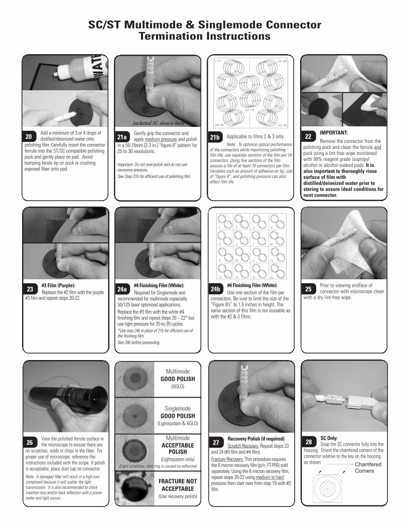
Remove the connector from thepolishing puck and clean the ferrule andpuck using a lint-free wipe moistenedwith 99% reagent grade isopropylalcohol or alcohol-soaked pads. It isalso important to thoroughly rinsesurface of film withdistilled/deionized water prior tostoring to assure ideal conditions fornext connector.
22
Prior to viewing endface ofconnector with microscope clean
with a dry lint-free wipe.25
View the polished ferrule surface inthe microscope to ensure there are
no scratches, voids or chips in the fiber. Forproper use of microscope, reference theinstructions included with the scope. If polishis acceptable, place dust cap on connector. Note: A damaged fiber will result in a high-losscomponent because it will scatter the lighttransmission. It is also recommended to checkinsertion loss and/or back reflection with a powermeter and light source.
26
SC/ST Multimode & Singlemode ConnectorTermination Instructions
#3 Film (Purple):Replace the #2 film with the purple
#3 film and repeat steps 20-22.
23
Applicable to films 2 & 3 only.Note: To optimize optical performance
of the connectors while maximizing polishingfilm life, use separate sections of the film per 14connectors. Using five sections of the filmassures a life of at least 70 connectors per film.Variables such as amount of adhesive on tip, sizeof “figure 8”, and polishing pressure can alsoaffect film life.
21b
#4 Finishing Film (White):Use one section of the film per
connectors. Be sure to limit the size of the“Figure 8’s” to 1.5 inches in height. Thesame section of this film is not reusable aswith the #2 & 3 films.
24b#4 Finishing Film (White):Required for Singlemode and
recommended for multimode especially50/125 laser optimized applications.Replace the #3 film with the white #4finishing film and repeat steps 20 – 22* butuse light pressure for 25-to-35 cycles.*Use step 24b in place of 21b for efficient use ofthe finishing film.See 24b before proceeding.
24a
Recovery Polish (if required)Scratch Recovery: Repeat steps 23
and 24 (#3 film and #4 film).Fracture Recovery: This procedure requiresthe 6 micron recovery film (p/n: FT-PF6) soldseparately. Using the 6 micron recovery film,repeat steps 20-22 using medium to hardpressure then start over from step 19 with #2film.
27
Add a minimum of 3 or 4 drops ofdistilled/deionized water onto
polishing film. Carefully insert the connectorferrule into the ST/SC compatible polishingpuck and gently place on pad. Avoidbumping ferule tip on puck or crushingexposed fiber onto pad.
20 Gently grip the connector andapply medium pressure and polish
in a 50-75mm [2-3 in.] "figure 8" pattern for25 to 30 revolutions.
Important: Do not over-polish and do not useexcessive pressure. See Step 21b for efficient use of polishing film.
21a
Jacketed SC shown here
MultimodeGOOD POLISH
(XGLO)
SinglemodeGOOD POLISH
(Lightsystem & XGLO)
MultimodeACCEPTABLE
POLISH(Lightsystem only)
FRACTURE NOTACCEPTABLE
(Use recovery polish)
SC Only:Snap the SC connector fully into the
housing. Orient the chamfered corners of theconnector relative to the key on the housingas shown.
28
Chamferedcorners Key
(Light scratches, dark ring is caused by adhesive)
Rev
. H
1
1/0
3
100.8
352
© 2
0003
The
Sie
mon
Com
pany
WARNING:Optical transmitters and fiber optic test equipment used in the
telecommunications industry uses invisible infrared energy.At sufficient power, this may cause eye or skin damage.
If you work with fiber optic products, including test equipment, consider the following:1. Do not look into fibers or connectors. They may be ‘live’.2. Know what is happening with the fiber under test at the far end!3. When connecting a light source, try to make it the last element you connect!4. Whenever possible, switch off and disconnect your light source(s) before breaking any fiber connections.5. Always consider the hazard to other people:
a. Use warning signs, etc.b. Keep caps on unconnected fibers whenever possible.c. If using “live” optical beams, keep them low and facing away from personnel.
6. Don’t view optical outputs with a microscope, use a TV camera/monitor.7. Elect a safety officer to:
a. Train staffb. Maintain records of equipment classification, calibrations and safety checks.
8. Be careful of cut fibers. Remember they are sharp and difficult to see!
SC/ST Multimode & Singlemode ConnectorTermination Instructions
POSSIBLE VARIABLES FORPOOR ATTENUATION OR RETURN LOSS READINGS
1. Fractured/broken fibers:- Dull cleaver- Dried adhesive on cleaver blade- Twisted or uneven pulling when removing stub- Bumped or brushed end-face of fiber before polishing- Too much pressure during initial pad polish or air polish
2. Adhesive/primer not curing:- Date code expired or exposed to extreme temperatures- Contaminated primer/adhesive- Not enough primer or adhesive- Did not allow enough cure time- Movement during cure time- Excessive buffer length pushing out adhesive during insertion
3. Excessive or insufficient polishing
4 Dirty pad, puck, paper, or end-face of connector
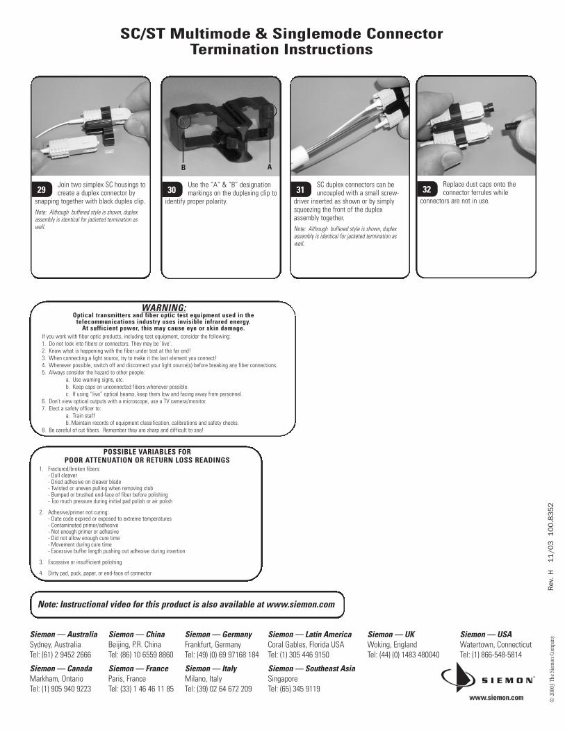
Replace dust caps onto theconnector ferrules while
connectors are not in use.32Join two simplex SC housings to
create a duplex connector bysnapping together with black duplex clip.Note: Although buffered style is shown, duplexassembly is identical for jacketed termination aswell.
29SC duplex connectors can beuncoupled with a small screw-
driver inserted as shown or by simplysqueezing the front of the duplexassembly together.Note: Although buffered style is shown, duplexassembly is identical for jacketed termination aswell.
31Use the “A” & “B” designationmarkings on the duplexing clip to
identify proper polarity.30
B A
Note: Instructional video for this product is also available at www.siemon.com
www.siemon.com
Siemon — UKWoking, EnglandTel: (44) (0) 1483 480040
Siemon — USAWatertown, ConnecticutTel: (1) 866-548-5814
Siemon — Australia Sydney, AustraliaTel: (61) 2 9452 2666
Siemon — Canada Markham, OntarioTel: (1) 905 940 9223
Siemon — China Beijing, P.R. ChinaTel: (86) 10 6559 8860
Siemon — FranceParis, FranceTel: (33) 1 46 46 11 85
Siemon — Germany Frankfurt, GermanyTel: (49) (0) 69 97168 184
Siemon — ItalyMilano, ItalyTel: (39) 02 64 672 209
Siemon — Latin America Coral Gables, Florida USATel: (1) 305 446 9150
Siemon — Southeast Asia SingaporeTel: (65) 345 9119