scrubber wet stack design guide
DESCRIPTION
EPRI Licensed MaterialThe expense of flue gas reheat has led to increased application of less expensive wetstacks downstream of wet FGD (flue gas desulfurization) systems. Good data isnecessary to properly design the wet stack system or serious problems can occur. Thisdesign guide summarizes all the latest information and provides guidance ondeveloping detailed design specifications.TRANSCRIPT

WET STACKS DESIGN GUIDETR-1070999017
Final Report, November 1996
Prepared byBURNS & McDONNELL ENGINEERING COMPANY4800 East 63rd StreetKansas City, Missouri 64130
Principal InvestigatorsS.M. AshtonJ.C. DeLayJ.B. LandwehrD.C. PattisonS.D. RichartC.V. Weilert
DYNAFLOW SYSTEMS9900 Erie StreetCambridge, Massachusetts 02139
Principal InvestigatorsG.B. GilbertL.A. Maroti
Prepared forElectric Power Research Institute3412 Hillview AvenuePalo Alto, California 94304
EPRI Project ManagerR.G. RhudyEnvironmental ControlGeneration Group
Effective December 6, 2006, this report has been made publicly available in accordance with Section 734.3(b)(3) and published in accordance with Section 734.7 of the U.S. Export Administration Regulations. As a result of this publication, this report is subject to only copyright protection and does not require any license agreement from EPRI. This notice supersedes the export control restrictions and any proprietary licensed material notices embedded in the document prior to publication.

DISCLAIMER OF WARRANTIES AND LIMITATION OF LIABILITIES
THIS REPORT WAS PREPARED BY THE ORGANIZATION(S) NAMED BELOW AS AN ACCOUNT OF WORK SPONSOREDOR COSPONSORED BY THE ELECTRIC POWER RESEARCH INSTITUTE, INC. (EPRI). NEITHER EPRI, ANY MEMBER OFEPRI, ANY COSPONSOR, THE ORGANIZATION(S) BELOW, NOR ANY PERSON ACTING ON BEHALF OF ANY OF THEM:
(A) MAKES ANY WARRANTY OR REPRESENTATION WHATSOEVER, EXPRESS OR IMPLIED, (I) WITH RESPECT TO THEUSE OF ANY INFORMATION, APPARATUS, METHOD, PROCESS, OR SIMILAR ITEM DISCLOSED IN THIS REPORT,INCLUDING MERCHANTABILITY AND FITNESS FOR A PARTICULAR PURPOSE, OR (II) THAT SUCH USE DOES NOTINFRINGE ON OR INTERFERE WITH PRIVATELY OWNED RIGHTS, INCLUDING ANY PARTY'S INTELLECTUALPROPERTY, OR (III) THAT THIS REPORT IS SUITABLE TO ANY PARTICULAR USER'S CIRCUMSTANCE; OR
(B) ASSUMES RESPONSIBILITY FOR ANY DAMAGES OR OTHER LIABILITY WHATSOEVER (INCLUDING ANYCONSEQUENTIAL DAMAGES, EVEN IF EPRI OR ANY EPRI REPRESENTATIVE HAS BEEN ADVISED OF THEPOSSIBILITY OF SUCH DAMAGES) RESULTING FROM YOUR SELECTION OR USE OF THIS REPORT OR ANYINFORMATION, APPARATUS, METHOD, PROCESS, OR SIMILAR ITEM DISCLOSED IN THIS REPORT.
ORGANIZATION(S) THAT PREPARED THIS REPORT
Burns & McDonnell, Kansas City, MissouriDyna Flow Systems, Cambridge, Massachusetts
ORDERING INFORMATION
Requests for copies of this report should be directed to the EPRI Distribution Center, 207 CogginsDrive, P.O. Box 23205, Pleasant Hill, CA 94523, (510) 934-4212.
Electric Power Research Institute and EPRI are registered service marks of Electric Power Research Institute, Inc.POWERING PROGRESS is a service mark of Electric Power Research Institute, Inc.
Copyright © 1996 Electric Power Research Institute, Inc. All rights reserved.

iii
REPORT SUMMARY
The expense of flue gas reheat has led to increased application of less expensive wetstacks downstream of wet FGD (flue gas desulfurization) systems. Good data isnecessary to properly design the wet stack system or serious problems can occur. Thisdesign guide summarizes all the latest information and provides guidance ondeveloping detailed design specifications.
BackgroundA wet stack is a chimney stack, or flue that exhausts saturated, completely scrubbed fluegas downstream from a wet FGD system. All recently designed and constructed wetFGD systems have installed wet stacks. The cost savings over reheating are verysignificant. However, there are a number of technical issues that utilities must addressto achieve a successful installation. This guide provides answers to these questionswhether the installation is new or retrofit.
Objectives• To provide background information and updates of previously publishedinformation.
• To summarize current state-of-the-art design.
• To list and discuss important parameters and options.
• To give specific recommendations for wet stack design.
Approach
Investigators collected the information from a literature survey, in-house expertise ofcontractors, phone contacts with vendors, a utility advisory committee, and a limitednumber of site visits. They collated and summarized the information to produce thereport, which the advisory committee also reviewed.
ResultsInformation in the guide covers the entire design spectrum for all three wet stackscenarios—a new plant with a wet stack (green field site), a retrofit FGD system with a

iv
wet stack, and conversion of an unscrubbed or reheated stack to wet stack operation.Some of the important issues addressed include regulatory considerations, stack liquiddischarge, plume downwash, corrosion/chemical attack, stack height, stack linergeometry, gas velocity in the liner, and liquid collection devices and drainage. Inaddition, the report also provides a guide to developing a wet stack specification.
EPRI PerspectiveBecause most new FGD systems include wet stacks, it is imperative that accurate,reliable information is available. This guide contains the most up-to-date informationand should be useful for personnel responsible for wet stack designs, specifications, oroperation. In addition, the survey of known wet stacks and the listings of suppliers,manufacturers, and contractors for wet stacks also should be good starting points forinformation on specific situations. Care must be taken to use these recommendationswith good engineering judgment and consideration to site specifics.
TR-107099
Interest CategoriesAir emissions control
KeywordsFlue gas desulfurizationWet stacksWet scrubbersSO2 control

EPRI Licensed Material
v
ABSTRACT
Because of the high cost of reheat, wet stacks are being considered for new or retrofitapplications of wet flue gas desulfurization (FGD) systems in the United States. Allretrofit systems designed for compliance with Phase I of the Acid Rain Control programunder the Clean Air Act have used wet stacks. For Phase II, utilities with existing wetFGD systems could benefit from overscrubbing. For those units that currently usebypass reheat, this could be accomplished by closing the bypass to treat the entire boilerflue gas stream. This would require conversion to wet stack operation.
Due to the level of interest in these wet stack scenarios for future FGD applications, theElectric Power Research Institute (EPRI), in a tailored collaboration with New YorkState Electric & Gas (NYSEG), retained Burns & McDonnell and DynaFlow Systems toprepare a design guide for wet stacks. The purpose of this guide is to provide the utilityindustry with information and recommendations concerning the design andspecification of wet stacks.


EPRI Licensed Material
vii
ACKNOWLEDGEMENT
This guide and the survey work to support it were performed under EPRI work orderWO9017-01. The authors would like to acknowledge the program advisory committeefor their guidance in the direction of the design guide project. The authors would alsolike to thank the committee members for their efforts in commenting on the draftversion of this guide. The program advisory committee members are:
David ClarkLos Angeles Metropolitan Water District
N.N. DarmarajanCentral & South West Services
John E. SmigelskiNew York State Electric & Gas
Tom WilsonPennsylvania Electric
Steve WolsifferIndianapolis Power & Light


EPRI Licensed Material
ix
CONTENTS
1 BACKGROUND AND OBJECTIVES ....................................................................... 1-1
1.1 Introduction ........................................................................................................ 1-1
1.2 Scenarios for Wet Stack Utilization .................................................................... 1-2
1.3 Problems with Reheat Systems ......................................................................... 1-3
1.3.1 Effectiveness ............................................................................................... 1-3
1.3.2 Economics/Thermal Efficiency..................................................................... 1-5
1.3.3 Maintenance ................................................................................................ 1-6
1.3.4 Reliability ..................................................................................................... 1-8
1.4 Important Considerations for Wet Stack Design and Operation......................... 1-8
1.4.1 Regulatory Considerations .......................................................................... 1-9
1.4.2 Sources of Liquid in Wet Stacks ................................................................ 1-10
1.4.3 Corrosion/Chemical Attack ........................................................................ 1-14
1.4.4 Plume Downwash ...................................................................................... 1-15
1.4.5 Icing Potential ............................................................................................ 1-16
1.4.6 Dispersion (Ground Level Concentrations Within Acceptable Limits)........ 1-17
1.4.7 Installed Costs ........................................................................................... 1-18
1.4.8 Maintenance Costs .................................................................................... 1-18
1.4.9 CEM Systems............................................................................................ 1-19
1.5 Contents of the Design Guide .......................................................................... 1-19
1.5.1 Information About Key Issues.................................................................... 1-19
1.5.2 Knowledge of the State-of-the-Art ............................................................. 1-19
1.5.3 Preliminary Assessment of Feasibility ....................................................... 1-20
1.5.4 Overview of Project Implementation .......................................................... 1-20
2 NEW/RETROFIT WET STACK DESIGN.................................................................. 2-1
2.1 Process That Leads to a Specification............................................................... 2-1
2.1.1 Phase I - Feasibility Study ........................................................................... 2-1
2.1.2 Phase II - Design Process ........................................................................... 2-4

EPRI Licensed Material
x
2.1.3 Recommendations....................................................................................... 2-6
2.2 Specific Design Issues ....................................................................................... 2-6
2.2.1 Gas Velocity in the Liner.............................................................................. 2-7
2.2.2 Stack Liner Materials of Construction .......................................................... 2-9
2.2.3 Miscellaneous Materials of Construction ................................................... 2-21
2.2.4 Height ........................................................................................................ 2-25
2.2.5 Foundation Requirements as Affected by Liner Choice ............................ 2-25
2.2.6 Geometry................................................................................................... 2-25
2.2.7 Liquid Collection Devices and Drainage .................................................... 2-37
2.2.8 Operating Conditions ................................................................................. 2-43
2.2.9 CEM System Considerations..................................................................... 2-50
2.2.10 Evaluation for Wet Operation................................................................... 2-51
2.2.11 Outage Time............................................................................................ 2-63
2.2.12 Cost ......................................................................................................... 2-64
3 CONVERSION TO WET STACK OPERATION ....................................................... 3-1
3.1 Process That Leads to a Specification............................................................... 3-1
3.1.1 Phase I - Feasibility Study ........................................................................... 3-1
3.1.2 Phase II - Design Process ........................................................................... 3-4
3.1.3 Recommendations....................................................................................... 3-5
3.2 Specific Design Issues ....................................................................................... 3-6
3.2.1 Gas Velocity in the Liner.............................................................................. 3-6
3.2.2 Chimney Inlet Considerations...................................................................... 3-7
3.2.3 Materials of Construction ............................................................................. 3-8
3.2.4 Condition of Existing Chimney and Ductwork ............................................ 3-12
3.2.5 Code Requirements for Stack Modifications.............................................. 3-13
3.2.6 Adequacy of Existing Chimney Foundation ............................................... 3-16
3.2.7 Adequacy of Existing Steel Stacks ............................................................ 3-16
3.2.8 Operating Conditions ................................................................................. 3-17
3.2.9 Wet Fans ................................................................................................... 3-19
3.2.10 Location of Opacity Monitors ................................................................... 3-20
3.2.11 Liquid Collection Devices and Drainage .................................................. 3-20
3.2.12 Laboratory Flow/Modeling for Conversion ............................................... 3-23
3.2.13 Evaluation of Performance Through Stack Droplet Testing..................... 3-24
3.2.14 Outage Time............................................................................................ 3-26
3.2.15 Cost ......................................................................................................... 3-27

EPRI Licensed Material
xi
4 GUIDE TO DEVELOP SPECIFICATIONS FOR WET STACKS .............................. 4-1
4.1 Step-by-Step Process ........................................................................................ 4-1
4.1.1 Establish Design Criteria ............................................................................. 4-1
4.1.2 Define Absorber Outlet Duct and/or Bypass Duct Geometry....................... 4-2
4.1.3 Define Chimney/Liner Geometry ................................................................. 4-2
4.1.4 Perform Model Study ................................................................................... 4-2
4.1.5 Determine Liquid Collection Devices ........................................................... 4-2
4.1.6 Prepare Bid Specifications........................................................................... 4-3
4.1.7 Prepare Bid Drawings.................................................................................. 4-3
4.2 What to Specify .................................................................................................. 4-4
4.2.1 General Requirements................................................................................. 4-4
4.2.2 Site Work ..................................................................................................... 4-7
4.2.3 Concrete ...................................................................................................... 4-8
4.2.4 Liner............................................................................................................. 4-9
4.2.5 Ductwork and Expansion Joints................................................................. 4-10
4.2.6 Miscellaneous Metals ................................................................................ 4-10
4.2.7 Insulation and Lagging .............................................................................. 4-11
4.2.8 Access Doors............................................................................................. 4-11
4.2.9 Protective Coatings.................................................................................... 4-11
4.2.10 Special Construction (Tuned Mass Damping System). ........................... 4-12
4.2.11 Personnel Elevator .................................................................................. 4-12
4.2.12 Mechanical .............................................................................................. 4-13
4.2.13 Electrical .................................................................................................. 4-13
4.3 What to Ask For ............................................................................................... 4-14
4.3.1 Warranties/Guarantees.............................................................................. 4-14
4.3.2 Design Calculations ................................................................................... 4-15
4.3.3 Materials Testing ....................................................................................... 4-16
4.3.4 Construction Procedures ........................................................................... 4-18
4.3.5 On-Site Testing and Inspection ................................................................. 4-20
5 REFERENCES ......................................................................................................... 5-1
A GLOSSARY .............................................................................................................A-1
A.1 Nomenclature .................................................................................................... A-1
A.2 Definitions.......................................................................................................... A-3
A.3 Abbreviations ................................................................................................... A-10

EPRI Licensed Material
xii
A.4 Units and Conversion Factors ......................................................................... A-12
B LIST OF KNOWN WET STACKS............................................................................B-1
C RESULTS OF SURVEY...........................................................................................A-1
C.1 Wet Stack Survey Data .....................................................................................C-1
C.2 Average Stack Velocities for Various Types of Lining Materials......................C-13
C.3 Exit Velocities for Existing Acid Resistant Brick Liners ....................................C-15
D STACK LIQUID DISCHARGE MEASURING TECHNIQUES ..................................C-1
E PROCESS FLOW CHART OUTLINES....................................................................C-1
E.1 Process Flow Chart Outline For New/Retrofit Wet Stack................................... E-1
E.2 Process Flow Chart Outline For Conversion to Wet Stack Operation................ E-5
F SUPPLIERS, MANUFACTURERS, AND CONTRACTORS FOR WET STACKS... F-1
F.1 The following is a list of several companies that manufacture chimney brick. ... F-1
F.2 There are two potassium silicate mortars conforming to ASTM C466 that arecommonly used for wet FGD applications:............................................................... F-1
F.3 Two of the largest manufacturers of flakeglass reinforced vinyl ester systems areas follows: ................................................................................................................ F-1
F.4 Three manufacturers of FRP liners are:............................................................. F-1
F.5 Suppliers of Alloy C276 and/or Alloy C22 are: ................................................... F-2
F.6 The following companies are the major manufacturers of lightning protectionsystems: ................................................................................................................... F-2
F.7 The major manufacturers of chimney elevators are:.......................................... F-2
F.8 Three major chimney design and construction companies specializing in newchimney construction, as well as modifications to existing chimneys are: ............... F-2

EPRI Licensed Material
xiii
LIST OF FIGURES
Figure 2-1 Chimney with Brick Liner 2-27
Figure 2-2 Chimney with Fiberglass Reinforced Plastic Liner 2-28
Figure 2-3 Chimney with Metal Liner Typical for Allloy, Glass Block or ProtectiveCoating Liner System 2-29
Figure 2-4 The Effect of Ambient Temperature on Condensation in Selected TypicalStacks 2-58

EPRI Licensed Material
xv
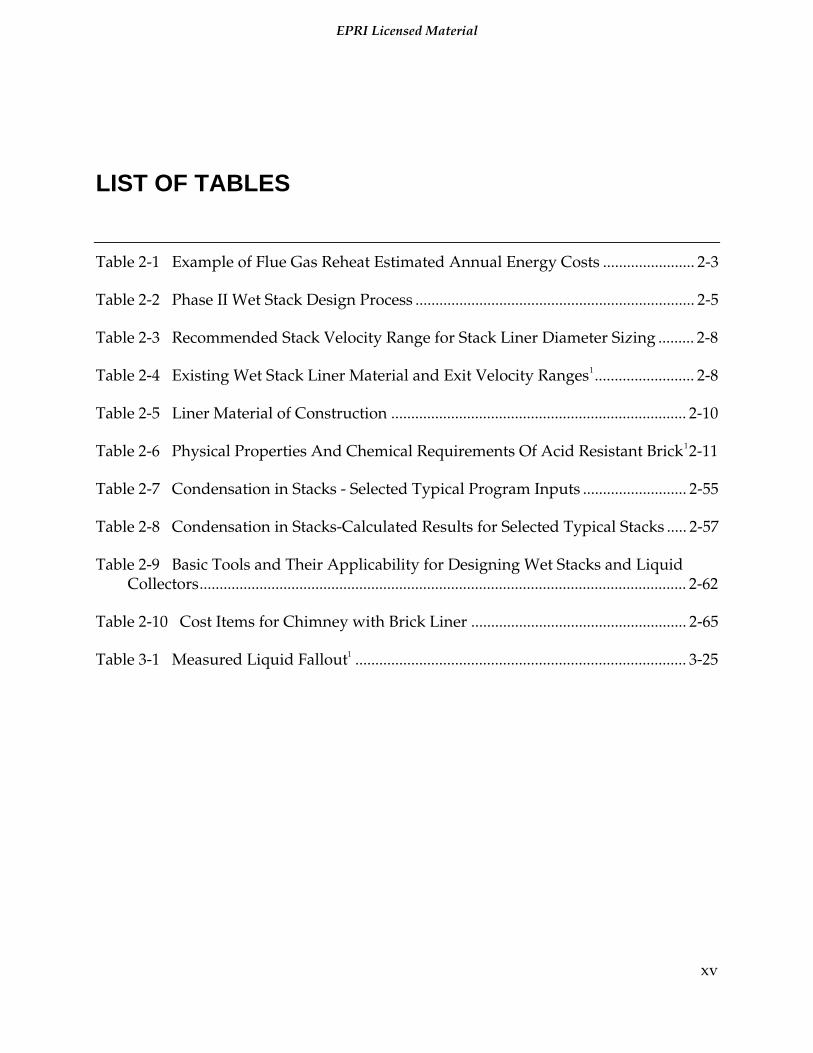
LIST OF TABLES
Table 2-1 Example of Flue Gas Reheat Estimated Annual Energy Costs ....................... 2-3
Table 2-2 Phase II Wet Stack Design Process ...................................................................... 2-5
Table 2-3 Recommended Stack Velocity Range for Stack Liner Diameter Sizing ......... 2-8
Table 2-4 Existing Wet Stack Liner Material and Exit Velocity Ranges1......................... 2-8
Table 2-5 Liner Material of Construction .......................................................................... 2-10
Table 2-6 Physical Properties And Chemical Requirements Of Acid Resistant Brick12-11
Table 2-7 Condensation in Stacks - Selected Typical Program Inputs .......................... 2-55
Table 2-8 Condensation in Stacks-Calculated Results for Selected Typical Stacks ..... 2-57
Table 2-9 Basic Tools and Their Applicability for Designing Wet Stacks and LiquidCollectors.......................................................................................................................... 2-62
Table 2-10 Cost Items for Chimney with Brick Liner ...................................................... 2-65
Table 3-1 Measured Liquid Fallout1 ................................................................................... 3-25

EPRI Licensed Material
1-1
1 BACKGROUND AND OBJECTIVES
1.1Introduction
A "wet stack" is a chimney, stack, or flue that exhausts saturated, completely scrubbedflue gas. A wet stack is located downstream from a wet flue gas desulfurization (FGD)system. These systems spray slurry into the gas stream, which reduces the sulfurdioxide (SO2) content, saturates the flue gas, and reduces the temperature of the flue gasto 115 to 130 degrees F. Wet stack operation discussed here does not use any flue gasreheat system or partial bypass.
The 1990 Clean Air Act Amendments (CAAA) require utilities to reduce emissions ofsulfur dioxide. Several utilities have added wet FGD systems to comply with Phase I ofthe CAAA. Other utilities have decided to eliminate partial bypass and scrub 100percent of their flue gas, to reduce sulfur dioxide emissions as part of their Phase IICompliance Plan. New or retrofit FGD systems typically use wet stack operationbecause of reduced operating and maintenance costs.
Elimination of stack gas reheat or partial gas bypass eliminates several problems.However, the design of stacks for wet operation must address several new issues thatwere not present in unscrubbed or reheated gas stack designs. Some of the importantissues to consider in the design of a wet stack include the following:
• Regulatory considerations.
• Stack liquid discharge.
• Plume downwash.
• Corrosion/chemical attack.
• Stack height.
• Stack liner geometry.
• Gas velocity in the liner.
• Liquid collection devices and drainage.
The economics favor wet stack operation as compared to stack gas reheat operation.However, there are trade-offs. It is important to make the correct decision, since theresults can have a significant impact on the capital and operating costs of an FGDsystem.

EPRI Licensed Material
Background And Objectives
1-2
The purpose of this guide is to provide the utility industry with information andrecommendations concerning the design and specification of wet stacks. However,these recommendations should not be used without applying good engineeringjudgment and consideration to site specifics. Operating conditions, design conditions,and economics all play important roles. Goals of the Wet Stacks Design Guide are to:
• Provide background information.
• Update previously published information.
• Present current state-of-the-art design.
• Identify the parameters and options that should be considered.
• Give specific recommendations regarding wet stack design.
It is assumed that those who will use this guide have a general familiarity with stackdesigns and FGD systems. This guide is intended for personnel responsible for designs,specifications, or operation of wet stacks.
The Wet Stacks Design Guide focuses on three different scenarios:
• A new plant with a wet stack (green field site).
• A retrofit FGD system with a wet stack.
• Conversion of an unscrubbed or reheated stack to wet stack operation.
Section 1 of this guide provides fundamentals on processes important to wet stacks anddiscusses objectives. Section 2 addresses new or retrofit wet stack design. Section 3discusses conversions to wet stack operation. A guide to develop specifications for wetstacks is presented in Section 4. Section 5 includes references and the Appendix includesa glossary, list of known wet stacks, results of the wet stacks industry survey, stackliquid discharge measuring techniques, and process flow chart outlines for new orretrofit wet stack designs and conversions to wet stack operation.
1.2Scenarios for Wet Stack Utilization
Designing the stack for wet operation without reheat is a viable option for a wet FGDsystem for both power plant designers and operators concerned with reducingmaintenance and increasing system efficiency. There are three primary scenarios forwet stack utilization:
• New unit with wet stack.
• Retrofit scrubber with wet stack.
• Conversion to wet stack operation.

EPRI Licensed Material
Background And Objectives
1-3
The first scenario occurs when adding a new unit that incorporates a wet scrubber and awet stack. In this case, the designer is given the most freedom regarding liner materialselection and stack geometry. State-of-the-art wet stack design should be used that isbased on the latest analytical, experimental and field data available. The goal is toproduce a design that minimizes corrosion problems and operating costs.
The second scenario is adding a new wet scrubber to an existing power plant. In thiscase, the most important design consideration is whether or not the existing stack, linerand ductwork are capable of accommodating the new wet environment from a materialstandpoint and from an operational standpoint. If not, then the existing chimney linermust be modified. Due to the outage time required to modify an existing stack, it isusually more economical to build a new stack for scrubbed gas and use the existingstack for gas bypass around the scrubber as needed.
The third scenario is operating an existing wet scrubber with reheat or some percentageof bypass. In order to decrease SO2 emissions and reduce operating and maintenancecosts, the unit would be converted to 100 percent wet operation which wouldcompletely eliminate reheat or gas bypass. Deciding whether to convert an existingstack to wet operation involves the ability of the existing material to withstand the cool,wet conditions and whether the gas velocity will result in moisture reentrainment fromthe stack walls. Required modifications could include the need to line the stack, buildliquid collection devices (such as drains and gutters) into the stack, or improving themist elimination system to limit droplet carryover.
1.3Problems with Reheat Systems
In the past, flue gas reheat systems (in-line, indirect hot air or direct combustion andbypass) have been specified to decrease moisture plumes and/or reduce ground levelSO2 concentrations. Unfortunately, these systems have proven to be overly expensiveand minimally effective. The minimal benefits associated with reheat have been welldocumented documented.(2). Reheat systems are quite expensive due to highinstallation and operating costs. In-line and indirect hot air systems also have highmaintenance costs and are likely to negatively affect plant reliability. Wet stackoperation offers advantages of improved thermal efficiency, reduced maintenance costs,and higher plant reliability. The issues related to problems with reheat are summarizedbelow.
1.3.1 Effectiveness
Reheat is utilized for both physical and environmental issues. Physical issues are theprevention of condensation or the corrosion of the duct and liner wall surfaces.Environmental issues are after the gas leaves the stack such as liquid fallout, plume rise

EPRI Licensed Material
Background And Objectives
1-4
and plume visibility. The effectiveness of reheat in serving these purposes is discussedin the following sections.
1.3.1.1 Physical.
Water that is not removed by the scrubber can condense on the duct walls and absorbSO2 to form dilute sulfuric acid in the ductwork and stack. Concerned about the stackliner's exposure to an acidic environment, many utilities have used stack gas reheat toincrease flue gas temperatures. Reheat increases the temperature of the flue gas abovethe water saturation level and helps evaporate some of the liquid. Reheat is intended toreduce or prevent condensation of vapor from the gas and promote evaporation ofliquid (suspended droplets and the liquid film on the walls), by decreasing the relativehumidity of the saturated, scrubbed gas. To completely prevent condensation in theduct and stack, it is necessary to keep the inside wall surface temperature above thedewpoint temperature of the stack gas mixture. The bulk of the stack gas must bemaintained at a high enough temperature to prevent water condensation on the ductand liner surfaces. A reheat system that is not operating properly would allow water onthese surfaces to absorb acid. Condensed acid deposition on these surfaces could causecorrosion.
Having sufficient heat capacity to evaporate droplets suspended in the gas flow doesnot assure complete evaporation. This is due to the limited rate of heat transfer to thedroplets. These droplets can range in size from small (1 to 30 µm), which are carriedover directly from the mist eliminators, to large (200 to 1000 µm), which are producedby reentrainment from the duct walls and also from carryover from the misteliminators, if plugged or not operating properly. Some reentrainment is virtuallyinevitable in a duct/stack system. Reheat will evaporate the fine mist (d<50 µm) but iscompletely ineffective in evaporating the larger droplets (d>200 µm) that have beenreentrained by the gas flow from the deposited liquid film. These droplets are too largeto be appreciably reduced in size by the reheat during the residence time in the ductand stack.
1.3.1.2 Environmental.
In addition to preventing condensation in the ductwork and stack, reheat is also usedto:
• Decrease stack liquid discharge.
• Increase plume rise.
• Eliminate a visible plume.
The large droplets are more likely to cause stack liquid discharge detectable at groundlevel near the stack. Reheat cannot be justified solely on the basis of eliminating stack

EPRI Licensed Material
Background And Objectives
1-5
liquid discharge. The large droplets are not evaporated because they do no have thesufficient residence time required to evaporate completely. They are only reduced insize. Reheat will lower the relative humidity of the flue gas. However, lower moisturecontent of the gas may result in higher acid concentrations in the droplet deposition.
Reheating provides about 10 to 20 feet (3-6m) of additional plume rise which is a smallincrease relative to the stack height. Therefore, this results in only a small decrease inground level concentrations compared to wet stack operation. In addition, there is anincrease in overall emissions from the plant on a pounds per million BTU basis as moreenergy is required for the same plant output. As indicated in Section 2, the estimatedannual energy costs for flue gas reheat on a 325 MW unit is $456,000.
Saturated flue gas will form a visible plume. A visible plume has no physical impact onthe environment, but it could be considered aesthetically undesirable. Prevention of avisible plume with reheat cannot be achieved within the normal reheat temperatureranges. Vapor plume formation is highly dependent on meteorological conditions. Theprevention of a visible plume by reheat under all meteorological conditions is beyondpractical limits. For the typical reheat case, the visible length of the plume is decreasedby approximately one-third the length of a wet plume.
1.3.2 Economics/Thermal Efficiency
In an economic evaluation, capital, operating and maintenance costs must beconsidered. The most significant disadvantage of a reheat system as part of the FGDprocess is cost. Reheaters are expensive. Capital costs associated with reheaters includethe costs of the reheat equipment and installation. Operating costs include energy andcapacity charges. The energy costs to reheat the flue gas are usually the most significantcosts. Operational costs are high due to the significant percent of boiler heat inputrequired. Installed reheat systems are an expensive consumer of energy. Maintenancecosts are difficult to determine, but should consider the labor and material expensesrequired to replace reheat coils. All of these costs should be evaluated whendetermining the economics of reheat.
The heat required to vaporize entrained liquid depends on the amount of liquidpresent, the thermal conductivity of the material, and the amount of heat loss to theenvironment. Residence time is usually not sufficient for reheat to evaporate the largedroplets in the flue gas stream. Also, the energy required to reheat the flue gas reducesthe thermal efficiency of the steam generating unit or boiler. For example, on a 600 MWunit, the unit derating resulting from reheater steam use was 1.4 percent. Additionalpower is also required for in-line reheat systems because of the pressure loss across thereheater tube bundles. These costs need to be included in the economic evaluation forreheat design.

EPRI Licensed Material
Background And Objectives
1-6
1.3.3 Maintenance
In general, reheat systems require a significant amount of upkeep. During a typicaloutage, plants with reheat systems put a large amount of labor and expenses towardrepairing their reheat system. This is especially true with in-line reheat systems notconstructed from corrosion resistant materials. Corrosion forces the removal of reheatertubes, and sometimes entire reheat systems require replacement. Pluggage is a majormaintenance item because the finned tubes installed in the heat exchanger are easilyfouled by deposits of solids. If a reheat system is used, corrosionand pluggage arereduced by using nickel alloy materials for the reheat system, using a pH controlsystem, and installing efficient mist eliminators.
1.3.3.1 Corrosion.
Corrosion of the various reheat systems used in FGD systems reduces unit efficiencyand requires expensive maintenance. In-line steam reheaters experience various levelsof corrosion ranging from moderate to extreme, depending on the materials ofconstruction. Chloride stress corrosion cracking and acid corrosion have been seriousproblems for in-line reheat systems. At many facilities, stress corrosion and acid attackhave forced the removal of reheater tubes; at several facilities, entire reheat systemshave required replacement. Without chlorides present, corrosion problems decreaseconsiderably when expensive higher grade alloys are used in manufacturing thereheater. Reheater corrosion problems usually require the unit to be off-line to make thenecessary repairs, which is another disadvantage of operating a reheat system.
Corrosion resistance and other advantages and disadvantages of different materials ofconstruction are provided in Table 2-5 in Section 2. To select corrosion resistantmaterials of construction for absorber outlet ducts and stack liners, it is important tounderstand the operating environment. There are basically four types of flue gas whichmay be present downstream of an FGD system:
• Unscrubbed or bypass flue gas.
• Scrubbed, nonreheated flue gas.
• Reheated, scrubbed flue gas.
• Partial bypass reheat or mixed flue gas.
Unscrubbed or bypass flue gas is typically 250 to 350 degrees F (121-177 °C), which isusually above the sulfuric acid dewpoint temperature. Depending on the sulfur contentof the coal and the moisture content of the flue gas, the sulfuric acid dewpoint of theunscrubbed bypass gas is 260 to 300 degrees F (127-149°C). Unscrubbed flue gasproduces an acid aerosol that is entrained in the gas stream. Corrosion in anunscrubbed duct/stack system is only a problem if the acid in the flue gas condenses,which will produce concentrated sulfuric acid.
EPRI Licensed Material
Background And Objectives
1-7
Scrubbed gas is typically 115 to 130 degrees F (46-54°C)and is completely saturated andmay contain condensed water. Scrubbed gas duct or liner surfaces are always wet andbelow the acid dewpoint and therefore require corrosion resistant material. Corrosionproblems with wet operation are less than with reheat operation. However, wetoperation may require a larger area of ductwork to be fabricated from corrosionresistant materials than reheat.
Reheated, scrubbed flue gas is typically 150 to 190 degrees F (66-88 °C). Stack gasreheaters normally provide 30 to 60 degrees F (17-34 °C) of reheat. The intent of reheatis to eliminate condensation. If liquid droplets are formed, they will be evaporatedthrough reheat. For aneffective reheat system, the flue gas must be reheated sufficientlyso that the resulting duct or liner wall temperature is above the dewpoint temperatureof the flue gas. In many installations, reheat systems have proven to be not totallyeffective. Corrosion of the ductwork in the mixing zone is typically a problem. Withreheat, the moisture in the flue gas is evaporated, which lowers the pH of the mixingzone and creates a more corrosive environment. (1,2). Louisville Gas and Electric MillCreek Units 1, 2, 3 and 4 has experienced downstream corrosion of carbon steelductwork due to ineffective reheat. Mill Creek Units 1 and 3 are being lined with AlloyC276. At TMPA Gibbons Creek, carbon steel absorber outlet ducts and duct to stack hadto be lined with vinyl ester coating due to corrosion.
Partial bypass reheat is the worst from a corrosion standpoint because of particulatebuildup and condensation of sulfuric acid. Wet scrubbers do a good job of removingremaining particulate from the gas stream. The FGD industry has learned throughexperience that of all the corrosive environments that can be found within a wetscrubber system, one of the most severe conditions is mixing scrubbed and unscrubbedflue gas. The scrubbed gas, which has passed through the absorbers, has already beendropped well below its acid dewpoint. Although this scrubbed gas does not contain anysignificant concentration of sulfuric acid vapor, its temperature is low enough to coolthe bypass gas stream significantly when the two flue gas streams are mixed. Thesulfuric acid dewpoint of the mixed gas will be about 250 degrees F (121 °C). (10). Thisis based on 15% moisture and 1.0 ppm H2SO4 in the flue gas.
The temperature of the metal surfaces in the ductwork downstream of the confluence ofthe bypass duct and the absorber outlet duct is typically at or below 200 degrees F (93°C). Bypassed or mixed gas coming into contact with these surfaces will result insulfuric acid condensation. The concentration of the acid that condenses will beapproximately 60 to 70 percent H2SO4 and is capable of producing severe corrosion ofductwork, dampers and stack liners. The continuous bypass flow provides anessentially unlimited supply of acid vapor for further condensation, which can result ina continuous cycle of condensation and corrosion. The moist flue gas will also causeparticulate scale to build up on duct or liner surfaces, which adds to the corrosionproblems.

EPRI Licensed Material
Background And Objectives
1-8
1.3.3.2 Pluggage.
A problem with in-line reheat is that tube bundles tend to plug. Plugging occurs whendissolved solids carry over from the absorber through the mist eliminator. Depositionof dissolved solids on the hot heat exchanger surface creates scaling on the tubebundles. Plugging can be a more severe problem than corrosion because it increasespressure drop across the reheater, thus decreasing heat transfer and increasing fandischarge pressure requirements.
In-line reheaters can also use pressurized hot water as the heating medium instead ofsteam. This type of in-line reheater, which operates at lower temperatures, tends tohave less corrosion but experiences more pluggage. Pluggage problems for pressurizedhot water systems have been a major maintenance item because the finned tubesinstalled in the heat exchanger are easily fouled by solids deposition. (13).
1.3.4 Reliability
The reliability of reheat systems is critical to the economics of operating a power plantand maintaining a clean environment. The FGD industry mistaken thought that simpleheat exchangers inside or outside the ductwork environment could be used at relativelyhigh operability rates. In fact, while corrosion prevention is the most commonly citedreason for using reheat, the reheat systems are subject to the very problems that theyare intended to prevent.
To avoid the problems with pluggage and corrosion, some plants use indirect hot airreheat. Indirect hot air reheat heats air in an external heat exchanger and then mixes itwith the exit flue gas. Indirect hot air reheat systems are more reliable than in-linereheat. Because these systems are normally external to the flue gas stream, they are notas prone to plugging or corrosion.
A very common reheat method is partial bypass reheat. Partial bypass reheat may notrequire the maintenance that other reheat systems require. However, this reheatmethod produces a very corrosive environment (sulfuric acid condensation andbuildup of solids) in the absorber outlet duct and stack and also increases SO2
emissions. Eliminating partial bypass reheat would decrease SO2 emissions and allowutilities to bank or sell the excess SO2 allowances.
1.4Important Considerations for Wet Stack Design and Operation
Several potentially important issues must be considered for the design of a wet stack. Asummary of these issues are presented in this Section. More detail will be presented inlater sections.

EPRI Licensed Material
Background And Objectives
1-9
1.4.1 Regulatory Considerations
To meet Environmental Protection Agency (EPA) regulations and appropriatelyaddress permitting issues, the following topics need to be considered:
1.4.1.1 Ground Level Concentrations/Dispersion Modeling.
Projects involving the construction of a new wet stack or the modification of an existingstack to wet operation must consider the effects of the pollutant emissions on ambientair quality. Ground level concentrations (GLC) must be attained so meet therequirements of the National Ambient Air Quality Standards (NAAQS). Demonstrationof NAAQS compliance by dispersion modeling is needed for the criteria pollutants -sulfur dioxide (SO2), nitrogen oxides (NOx), and particulate matter less than 10 micronsin size (PM-10). Prevention of significant deterioration (PSD) increments also exist forSO2, NO2, and PM-10. The purpose of the PSD program is to prevent large increases inGLC in attainment areas. The cumulative increase in GLC is accounted for since thebaseline data must not exceed the PSD increment. The state/local air quality controlprogram must track changes in increment consumption through modeling. Changes tostack parameters associated with conversion to wet stack operation might requirereassessment of increment consumption. Dispersion modeling uses computationaltechniques to estimate atmospheric concentrations of contaminants from different typesof sources.
1.4.1.2 Permitting Issues.
With regard to PSD permit program applicability, an existing stack that has beenmodified through physical change or change in method of operation will not require apermit unless there is an accompanying increase in emissions. However, an air qualityimpact analysis may be required by the EPA, state, or local air quality agency. Inconjunction with this analysis, the issues of stack height and dispersion techniques mustbe addressed. For new stacks, good engineering practice (GEP) stack height regulationsapply. The GEP height is a function of the height of the building or other nearbystructure. The stack height regulation is covered by the EPA in Title 40 Code of FederalRegulations (CFR) Part 51. Most states have adopted stack height regulations consistentwith these federal requirements.
These regulations require that the degree of emissions limitation required for control ofan air pollutant shall not be affected by the portion of the stack height above GEP, or byany other dispersion technique. Dispersion techniques include the manipulation ofstack parameters. Installation of a choke on a stack would constitute a dispersiontechnique. The regulations do not prohibit the installation of a choke. Rather, theyprohibit inclusion of its effect on plume rise in the air quality analysis or in the setting ofemission limits.

EPRI Licensed Material
Background And Objectives
1-10
1.4.2 Sources of Liquid in Wet Stacks
The liquid inside the stacks comes from the moisture content of the gas flow enteringchimneys of units with a wet FGD system. The moisture is vapor in the gas anddroplets of various diameters carried by the gas stream. The vapor content is usuallythe maximum that can occur when the flue gas is saturated with water vapor. If there isan induced draft (I.D.) fan between the absorber and the stack, the fan temperature risewill result in a lower than saturation vapor content. What happens to the vapor andliquid content before the gas reaches the top of the liner defines how much liquid and inwhat form it is discharged from the stack. The major gas liquid flow processes that maylead to the stack liquid discharge are described in the next four subsections, includingthe major features of the stack liquid discharge. A description of the liquid flow balancein wet stacks is provided on pages 4-3 to 4-5 of Reference (1). Liquid flow rates typicalfor wet ducts and stacks are given in Section 2, "Condensation Calculations."
1.4.2.1 Mist Eliminator Carryover.
The gas stream leaving the mist eliminator is saturated with water vapor and entrainedfine liquid droplets are carried by the gas flow under ideal design and operatingconditions. It is important that the mist eliminators operate properly to minimize thesize and rate of droplet carryover. The mist eliminators are meant to reduce carryoverof liquid and slurry to the downstream ductwork. Mist eliminator problems can resultin increased liquid carryover. Some larger droplets may also be present in the gasstream that have been reentrained from the mist eliminator blades, the mist eliminatorsupport structure, and areas of solids buildup on the mist eliminator. During the washcycles, washing the mist eliminator can also increase the amount of liquid carried withthe gas flow downstream of the mist eliminator.
A field evaluation of the mist eliminator performance can be made by performingvisual inspections. If carryover problems are noticeable, stack liquid discharge isprobable if effectiveliquid collectors are not installed in the duct and the stack. The misteliminator selection, operation performance and possible problems are described inReference (3).
1.4.2.2 Deposition of Entrained Liquid Droplets.
As droplets flow with the flue gas, they will impinge on internal surfaces due to droplettrajectory paths controlled by the earth's gravity, centrifugal forces on the dropletswhen the gas flow turns, and gas drag forces. Large droplets (100-2000 µm) depositmore readily from the gas flow path, intermediate droplets (10-200 µm) depositpartially, and small droplets (0.1-10 µm) deposit hardly at all. The higher the gasvelocity and sharper the turn of the flue gas path, the more likely that significant

EPRI Licensed Material
Background And Objectives
1-11
numbers of droplets will impinge on walls, turning vanes, baffles, and on internal ductcomponents (bracing, gusset plates and expansion joints).
Small to medium droplets can also deposit on surfaces due to gas flow patterns inseparation regions and by turbulent deposition. The turbulent deposition of finedroplets due to adiabatic condensation (due to pressure reduction with elevationchange) along the height of the stack is small. The gas velocity, duct geometry, stackgeometry, and droplet size govern the amount and location of liquid deposition. Themajor deposition area in the stack is on the liner opposite of the breeching duct.
Liquid deposition can be promoted and liquid collected by properly designed collectiondevices, vanes, and baffles installed in the duct system. Maximum deposition andcollection of the liquid on the duct walls and stack liners must be achieved in order tocontrol stack liquid discharge. One of the main objectives of physical flow modeling isto design and develop liquid collectors such as ceiling gutters, side wall channels, andfloor guides to collect deposited liquid before reentrainment can take place. Thisprocess is discussed in Section 2 under "Laboratory Flow Modeling."
Another deposition area is on the choke surface in stacks that have chokes. Some of thefine droplets entrained in the gas flow will be deposited on the choke surface and theliquid collected on the choke will lead to stack liquid discharge if the local gas velocitiesin the choke are high enough to drag the liquid up to the top of the choke.
1.4.2.3 Condensation.
One of the sources of liquid in the wet duct/stack system is condensation of watervapor from the saturated gas flow. Two types of condensation take place in wet stacks.
Adiabatic Condensation (or bulk condensation) occurs in the bulk of the gas as thepressure of the saturated gas flow decreases due to pressure loss and elevation changealong the height of the stack. The decrease of absolute pressure of the saturated gascauses water vapor to condense on other fine droplets or small solid particles in thebulk of the gas. Droplets formed by this heterogeneous condensation will tend to bevery small. Only a very small fraction of this adiabatic condensation reaches the linersurface by turbulent deposition process. The rest is discharged, which creates thefamiliar white plume and evaporates as the plume mixes with the outside air.
Thermal Condensation (or wall condensation) due to heat transfer is important in wetstacks. Since the saturated flue gas temperature is usually between 120 to 130 degrees F(49-54 °C), heat transfer through the liner, the annulus and the concrete shell to thecooler surrounding ambient air causes water vapor to condense on the inside of thestack liner. The rate of condensation due to heat transfer are functions of the liner andshell construction and the liner insulation, the gas flow conditions, and the atmosphericconditions (i.e., ambient temperature, wind velocity, and barometric pressure.).

EPRI Licensed Material
Background And Objectives
1-12
Annulus pressurization of the brick liner stacks increases the rate of condensation onthe liner surfaces. Leakage of pressurizing air through the liner in older brick stacks cansignificantly increase the condensation. Insulation of alloy and FRP liners reduces thethermal condensation rate significantly. Condensation rates are calculated for threeselected typical stack designs in Section 2 under "Condensation Calculations."
1.4.2.4 Reentrainment.
The liquid on the liner surface produced by deposition and condensation flows in theform of film or rivulets as governed by gravitational, surface tension, and gas shearforces. The gas shear force can shear the liquid off the surface, causing reentrainment.This is the most frequent source of stack liquid discharge and fallout of liquid dropletsin the vicinity of the stack.
Reentrainment most frequently occurs because of one or more of the following:
• High gas velocity shear near rough surfaces with liquid deposits.
• Instability of the liquid film (waves and ripples) on vertical stack liner surfaces. Thisoccurs because as gravity is pulling the liquid film or droplet down, the gas dragforces are pulling the liquid film or droplet upward.
• Surface discontinuities and protrusions that disrupt gas and liquid flow locally.
• Vanes and baffles that cause gas flow separation and recirculating liquid flow andreentrainment.
• Gas flow patterns that drag liquid along the surface to reentrainment sites.
• Strong vortex patterns that can pick water up in the core of the vortex fromhorizontal or vertical surfaces.
Reentrainment takes place at locations such as:
• Duct walls, roofs, floors, and stack liner surfaces.
• Dampers, damper blade guides, and trusses.
• Thermal expansion joints.
• Trailing edges of turning vanes.
• Duct junction corners.
• Breeching duct area changes.
• Stack floor.
• Stack liner surface, particularly in the entrance region and the intersection with thebreeching duct.
• Internal solid buildup or scaling on surfaces.

EPRI Licensed Material
Background And Objectives
1-13
• Stack liner contraction sections.
• Stack choke surfaces.
Liquid reentrainment at these locations will be in the form of large droplets (200-1500µm) and will be discharged at the top of the stack if not prevented by a combination offavorable gas flow path design and an optimized liquid collector system. Droplets over100 µm do not evaporate outside of the stack and they will likely reach the groundlevel.
1.4.2.5 Washing of Wet Fans.
Occasionally, induced draft fans will be located between the absorbers and the stack ofa utility power plant when retrofitted with an FGD system. These fans usually requireperiodic or continuous washing to prevent solids buildup on the fan impellers, whichcan cause fan rotor imbalance. All of the liquid sprayed into the fan inlet leaves the fanimpeller as droplets. Most of the liquid will be propelled by the high centrifugal forcefield to the fan scroll, where it deposits but immediately reentrains due to the high gasstream velocity. Most of the washing liquid will escape the fan discharge as dropletsentrained in the gas stream, causing additional liquid load in the ducts and in the stack.Fans should preferably be located upstream from the absorber to avoid these problems.
1.4.2.6 Stack Liquid Discharge.
The stack liquid discharge (SLD) is also known as rainout or acid mist fallout. It isimportant to note that all wet stacks have some amount of stack liquid discharge.However, stack liquid discharge is only a problem if the droplets are large enough thatthey are detectable at ground level near the stack.
The amount of liquid discharged at the top of the stack is a result of gas and liquid flowprocesses that take place in the ductwork and stack system between the discharge of theabsorbers and the top of the stack liner. The source of the liquid discharge can becategorized by the liquid flow process and by the droplet sizes as follows:
• Liquid droplets carried from the absorber to the top of the stack liner by the gasstream without depositing along the gas flow path. Only small droplets (<50 µm)travel through theducts without deposition. This means that most conventionalscrubber designs, with horizontal ducts connecting the absorber to the stack, willresult in deposition of most large droplets on the duct surfaces.
• Droplets reentrained from liquid deposition and condensation on duct surfaces thatcan be discharged. These are large drops and they are usually the major contributorsto the stack liquid discharge.

EPRI Licensed Material
Background And Objectives
1-14
• Droplets formed by bulk condensation. These represent a large liquid flow rate butvery fine droplets, which results in a negligible effect on the stack liquid dischargesdetectable at ground level.
• Liquid deposited and condensed on the liner flows upward in those areas of thestack where the gas velocity is higher than the flow reversal velocity for the linermaterial. The droplet sizes reentrained at the top of the liner where velocities arehighest can be quite large (300-2000 µm), depending on the liner top geometry. Theupper section of a stack choke is usually in this mode of upward liquid flow.
The quantity and location of the fallout at a given plant is a function of the droplet sizedistribution of the discharged liquid and atmospheric conditions such as ambienttemperature, wind, relative humidity, and turbulence level. The very small droplets ofthe bulk condensation make the gas plume white and visible. The plume is cooled as itmixes with the surrounding air. This cooling results in condensation on the smalldroplets in the plume. The increase in diameter is only 1 to 10 µm, and therefore, thedroplets of the bulk condensation do not fall to the ground and cannot be detected. Themixing with the drier air away from the stack causes droplet evaporation. The balancebetween the cooling and mixing processes defines the length of the visible plume.Therefore, it is a function of the ambient air temperature and the air relative humidity.
One of the major objectives in developing an effective wet stack design is to limit stackliquid discharge to a minimum acceptable level. The purpose is to limit the droplet sizethat will exit the stack. If the droplets are small enough they will evaporate beforehitting the ground. However, if the droplets are large they will land on plant structures,equipment, cars, etc. Based on the wet stack survey, fallout of liquid droplets, ifnoticeable, occurs usually within a half-mile radius of the stack.
1.4.3 Corrosion/Chemical Attack
With wet stack operation, corrosion is less severe than with reheat but it still must beconsidered. However, the corrosion can be prevented. The floors of the ductworkshould be sloped to provide proper drainage of the corrosive liquid after shutdown ofthe unit. The exposed materials of the ductwork and the stack liner must be resistant tochemical attack. Several types of material are available for both the scrubber outlet ductand the stack liner. The materials are selected considering their corrosion resistance tothe chemical properties of the flue gas downstream fromthe absorber. Corrosionprevention can be achieved with current liquid collection technology and materialavailability. Refer to Section 2 of this design guide dealing with materials ofconstruction for more information.
EPRI Licensed Material
Background And Objectives
1-15
1.4.4 Plume Downwash
Designing for a low velocity plume can decrease the amount of stack liquid discharge.However, it increases the potential for plume downwash at elevated wind velocities.During downwash episodes, saturated flue gas comes in contact with the linerextension, stack hood and stack shell. This can lead to deterioration of the stackconstruction materials due to exposure to acid in the flue gas. It also increases thepotential for ice formation on the top of the stack. The potential deterioration problem isa long-term situation caused by continual exposure to SO2 and has been evident inrecent years by the deteriorating conditions of tombstones, stone buildings, and the topof stack shells. The icing problem can occur at below freezing conditions all winter long,every winter, and creates a potential danger to people and property. Across-wind at thetop of the stack will deflect the plume from its vertical path. As the ratio of verticalplume momentum to horizontal wind momentum (( ) / ( ) )ρ ρV V2
FLUEGAS2
WIND falls belowa value of about 2.0 for a single flue stack, the plume may become partially entrained inthe vortex patterns that are formed on the downwind side of the stack. Thisphenomenon is known as plume downwash. To reduce the frequency of downwash, themomentum ratio must be increased, either by reducing the liner diameter or byinstalling a choke at the top of the liner.
For a multiple flue stack, the equivalent momentum ratios for initiation of plumedownwash are higher and vary with the wind direction. The reduced static pressure inthe wind vortices generated off the stack shell and liner extensions can draw the fluegas into a downwash pattern along the stack shell. In the process, the saturated fluegases that are drawn into the vortices come into contact with the roof and sides of thestack liner and shell.
The interaction of a plume with the across-wind is a function of the followingparameters:
1. Stack and liner geometry such as:
• Liner extension diameter.
• Shell diameter.
• Liner extension.
• Roof shape.
• Number of liners.
2. Wind direction, velocity, and air density at the top of the stack.
3. The annual frequency of wind occurrence as a function of wind velocity.
4. Liner exit gas velocity and gas density.

EPRI Licensed Material
Background And Objectives
1-16
5. Plume buoyancy due to flue gas temperature.
The most important fluid dynamic parameter is the momentum ratio between the stackexit flow and the across-wind. This ratio defines the relative influence of each flow uponthe other and is determined by the densities and velocities of the flue gas and the wind.This momentum ratio is defined as (ρV2)FLUEGAS/(ρV2)WIND). Plume downwash is mostlikely to occur during reduced unit load operation where stack discharge velocities arereduced and during high wind conditions. Plume downwash is least likely to occurunder the opposite conditions of high unit load operation and low wind velocity. For amultiple flue stack, the liner extension height above the shell is also very important forminimizing plume downwash. The selection of the stack top geometry and stackdischarge velocity for good plume escape must also consider the stack dischargevelocity for plume dispersion and stack liner velocity. This is to prevent reentrainmentof liquid from the stack liner, expansion joints, and stack choke.
1.4.5 Icing Potential
Whether ice forms on the top of the stack depends on the temperature of the surface,the temperature of the mixture of saturated flue gas and cold ambient wind, andwhether water vapor will condense out of the mixture. Ice formation is most likely atplants where below freezing temperatures are common and last for extended periods oftime.
The locations for potential ice formation are discussed below:
The linerextension forsingle ormultipleliners
- The liner extension is the first element exposed to plume downwash.If the liner extension is liners uninsulated, the surface should alwaysbe above freezing temperature. No ice could form but somecondensation might occur that would then run down to the stackroof.An insulated extension might have some ice formation.
The hood fora single fluestack
- The hood is the second element exposed to plume downwash. A hoodfor a single flue stack is usually connected to the stack, liner, and linerextension, which helps to keep it warm. When ice forms on anoutward sloping hood, it usually forms off the upwind edge and/orin the downwind half at two locations about 45 degrees off the axis ofthe wind direction. These icicles form similar to those on the roofvalley of a house.
The roof of amultipleliner stack
- The stack roof usually does not directly touch the liners to permitexpansion and movement of the liners. The roof will receive heatfrom inside the stack. Liquid must be drained from the roof area.Drains should preferably be located on the inside of the column to

EPRI Licensed Material
Background And Objectives
1-17
keep from freezing.
Railings - The metal railings at the top of the shell will quickly cool to themixture temperature of the flue gas and ambient air and will be thefirst surfaces to form ice. This is the most likely place for ice to form.
Platformnear top ofstack
- A metal platform on the outside of the stack near the top can also beexposed to low concentrations of flue gas. Since it is metal andexposed to the ambient and flue gas mixture temperature, it may alsoexperience occasional ice buildup. This is the second most likely placefor ice to form.
Shell - The shell will receive some heat from inside the stack. If ice forms onthe shell, it is expected to be in the downwind side of the stack. Thiscondition occurs when visible downwash can be seen on thedownwind side of the stack shell.
Icing usually does not cause serious ice buildups that can fall to the ground. However,when the icing conditions are occurring, the platform near the top of the stack, therailings, and possibly the roof may be slippery.
The potential for icing can be reduced by the following steps:
1. Select a stack liner discharge velocity that minimizes plume downwash over theexpected operating range of the unit at the existing local wind conditions and that isconsistent with other design objectives.
2. In cold ambient temperature with high wind conditions, run the unit near full load.This may be a natural situation, since more power is consumed in below freezingweather.
3. Use heated annulus air or electrical heating elements to heat the stack hood or roofor other areas where ice forms on the top of the stack.
4. Insulation is not required on sloped rainhoods constructed of a corrosion resistantmaterial.
1.4.6 Dispersion (Ground Level Concentrations Within Acceptable Limits)
In addition to emission standards, power facilities must meet standards for groundlevel concentrations set by state and federal regulations. Meeting emission standardsdoes not assure the meeting of ground level concentration standards. Ground levelconcentrations (GLC) aredependent on emissions, stack height, flue gas characteristics,nearby terrain and building features, and meteorological conditions. Flue gas from awet stack system is cooler and therefore less buoyant than reheated flue gas, so stackgas reheat systems should have lower ground level concentrations than wet systems.

EPRI Licensed Material
Background And Objectives
1-18
Based on previous experience, actual modeling rarely shows reheat to be the differencebetween compliance and noncompliance.
If predicted ground level concentration modeling from new or modified sources provesto be a problem, a number of methods to decrease concentrations through reducedemissions can be examined as part of a feasibility study. For new sources, increasedstack height could be considered. SO2 removal efficiency may also be enhanced by usingdibasic acid (DBA) or by mechanical modifications to the design of the absorbers. Thiscould offset the increase in ground level concentrations caused by eliminating reheat(lower plume rise). Meeting ground level concentration standards through reduction inemissions is likely to be a more effective solution than stack gas reheat.
1.4.7 Installed Costs
The installed cost of an FGD system without reheat may be lower than the installed costof a FGD system with reheat. (4).
A wet stack system does not require additional fuel costs or equipment costs associatedwith reheat. These costs however are partially offset by the more expensive linerconstruction material required for the corrosive environment of a wet stack and by thelarger liner diameter required to promote liquid collection.
The height and diameter of a wet stack can be minimized by controlling the quantityand size of liquid droplets entering the stack. Components (liquid collectors and drains)to reduce the quantity and size of liquid droplets entering the stack should be used ifthey are more cost-effective than a larger stack. In addition, stacks can be reduced insize by selecting alternative liner materials that allow a higher stack velocity.
1.4.8 Maintenance Costs
A wet FGD system operating without reheat may typically have lower maintenancecosts than a FGD system with reheat.
Partial bypass reheat requires additional ductwork that needs to be maintained. Thearea where the bypass ductwork meets the outlet ductwork is a highly corrosiveenvironment and is usually a high maintenance area.
Wet stack operation requires less equipment to be maintained. In-line reheaters requireroutine maintenance of piping, valves, reheater tubes, condensate drain traps, etc. In-line reheaters also require periodic replacement due to corrosion.

EPRI Licensed Material
Background And Objectives
1-19
1.4.9 CEM Systems
The Continuous Emission Monitoring (CEM) Systems requirements for wet stackapplications are generally the same for unscrubbed and reheat applications with theexception of monitoring opacity. Opacity monitors will not function properly in a wetstack because water droplets will result in high opacity readings. The EPA hasexempted wet stack units from monitoring opacity that are otherwise, affected by theacid rain program. However, no such exemption has been granted for new sourceperformance standard units. In addition there may be local requirements for monitoringopacity.
1.5Contents of the Design Guide
The main contents of the design guide is presented to provide the industry withinformation concerning the design and specification of wet stacks.
1.5.1 Information About Key Issues
A main objective of the Wet Stacks Design Guide is to provide the latest informationabout key issues. For example, the design guide contains discussion on gas velocity,liner materials of construction, liquid collection devices and drainage, continuousemissions monitoring systems, flow modeling, etc. This guide is not a step by stepguide, but is intended to provide background information and identify the parametersto consider in wet stack design, in order to help utilities and engineers select the rightpath. A key to successful design of a wet stack is understanding the choices available.This design guide focuses on what options should be considered, what the constraintsare, and what effect variations in the parameters have on the design of a wet stack. Forexample, the design guide discusses the impact a choke has on a brick lined chimneyand the options available regarding alloy liner construction.
1.5.2 Knowledge of the State-of-the-Art
Another main objective of this Wet Stacks Design Guide is to summarize the latesttechnology available regarding wet stacks. This design guide is a follow-up to EPRI'sReport CS-2520 Entrainment In Wet Stacks (1), that was published in 1982. The Wet StacksDesign Guide contains a presentation of the latest information available, updating whathas been done in the last 12 years. A total of twenty five existing units were retrofittedwith wet scrubbers under Phase I of the 1990 Clean Air Act Amendments. Each of theseunits has a wet stack. This design guide will summarize the latest wet stack technologyused for the Phase I scrubber projects, as well as new units that are under constructionand units that have eliminated reheat and converted to wet stack operation.

EPRI Licensed Material
Background And Objectives
1-20
1.5.3 Preliminary Assessment of Feasibility
New or retrofit FGD units are typically designed for wet stack operation. A feasibilitystudy is normally conducted to determine layout, materials of construction, economics,construction time, etc. The Wet Stacks Design Guide addresses what needs to beconsidered during the feasibility study phase of a new or retrofit wet stack project. Thedesign guide also identifies what needs to be considered when studying a conversion towet stack operation. For example: Will the existing stack exit velocity be acceptable forwet stack operation? Is the existing stack liner material acceptable from a corrosionstandpoint or does it need to be relined? How much outage time will be required tomake the conversion? Does the existing stack need to be repermitted?
1.5.4 Overview of Project Implementation
The Wet Stacks Design Guide is intended to provide the wet stack designer withinformation and recommendation concerning the design and specification of wet stacks.A systematic process is provided in Sections 2 and 3 to assist the designer in identifyingthe important issues that need to be addressed in the design process.
The design guidelines are provided in two phases: the feasibility study and the designprocess. These phases provide the designer with the process that leads to a bidspecification and identifies what to specify for work scope, what information to providein the specifications, and what to expect in terms of state-of-the-art operation.
During project implementation it is important that the model study vendor review thepreliminary wet duct/stack layout in order to minimize pressure loss and optimizeliquid collection and drainage. A flow model study needs to be performed during thedesign process in order to determine liquid collection devices and minimize stack liquiddischarge.

EPRI Licensed Material
2-1
2 NEW/RETROFIT WET STACK DESIGN
2.1 Process That Leads to a Specification
The designer must follow a logical process to develop a bid specification for a new orretrofit wet stack . This involves evaluating specific design issues that are important towet stack design. The engineering process that leads to a bid specification and thecompletion of a wet stack design is discussed in this section. The Wet Stacks DesignGuide provides a step-by-step process that leads to a bid specification.
The design of a new or retrofit wet stack may be broken down into two distinct phasesof work:
Phase I - Feasibility StudyPhase II - Design Process
A process flow chart outline is included in Appendix E.1 and provides more detailregarding the description of each major design issue.
2.1.1 Phase I - Feasibility Study
The Phase I feasibility study includes the following steps:
1. Address regulatory issues.
2. Define existing plant considerations.
3. Define operating parameters.
4. Determine stack height.
5. Establish liner material options.
6. Perform operating conditions vs. liner design compatibility analysis.
7. Select design velocity limit to prevent liquid reentrainment for each candidate linermaterial.
8. Perform a preliminary economic analysis of liner material options for wet stackoperation.

EPRI Licensed Material
New/Retrofit Wet Stack Design
2-2
9. Select liner material(s) for wet stack operation.
10. Determine reheat system design requirements (if necessary).
11. Perform economic analysis of wet stack vs. reheat operation (if necessary).
12. Select wet stack or reheat operation (if necessary).
The wet stack decision process needs to include a feasibility study comparing wet stackversus reheat unless it has already been decided to utilize wet stack operation, then theactivities involving comparison with reheat can be deleted. The study should includepermit considerations, dispersion modeling, preliminary design choices (such asvelocity limits for liner materials), and preliminary economics.
The study should consider the tradeoff between SO2 removal efficiency and velocity/liner material and ground level concentrations. Obtaining an air permit is an importantissue and will determine whether or not a utility can operate with a wet stack. Thefeasibility study should address all considerations necessary to make sure that the wetstack design will work.
2.1.1.1 Identification of Issues (Phase I)
A number of important issues must be addressed during the Phase I feasibility studyfor the design of a new or retrofit wet stack. This includes the following:
• Gas velocity in the liner.
• Liner materials of construction.
• Miscellaneous materials of construction.
• Stack height.
• Foundation requirements as affected by liner choice.
• Geometry.
• Liquid collection devices and drainage.
• Operating conditions.
• Continuous emissions monitoring (CEM) system considerations.
• Evaluation for wet operation.
• Outage time.
• Cost.
A detailed discussion of each issue that is important to new or retrofit wet stacks isincluded in this section of the design guide.

EPRI Licensed Material
New/Retrofit Wet Stack Design
2-3
2.1.1.2 Evaluation of Issues (Phase I)
During the wet stack Phase I feasibility study phase, several critical issues must beevaluated. For example: What material will be used for construction of the stack liner?The liner diameter is established based on liner material. Each of the specific designissues identified in this section needs to be evaluated from a technical and an economicsstandpoint for the wet stack designer to decide how to proceed.
2.1.1.3 Economics (Phase I)
Economic evaluation of a new or retrofit wet stack should include the following factors:
• Capital costs.
• Operating costs.
• Maintenance costs.
• Outage costs.
Capital costs for a chimney include the cost of the concrete shell, liner, foundation, andmiscellaneous items such as access platforms, doors, elevator, rainhood, pressurizationsystem, drain system, protective coatings, electrical, etc. Capital costs for a reheatsystem include the reheaters, supports, piping, valves, condensate traps, heatexchangers and pumps (for hot water reheaters), controls, insulation, etc.
Operating costs for a wet stack are small compared to a reheat system. If the liner isconstructed out of acid resistant brick then pressurization fans are required, which havean operating cost. Reheat systems typically have high operating costs due to the energyusage. A sample calculation of in-line reheat energy costs is shown in Table 2-1.
Table 2-1Example of Flue Gas Reheat Estimated Annual Energy Costs
Assumptions
Flue Gas Flow Rate 1,300,000 acfm (610 m3/s)@ 175 degrees F (79°C)
Flue Gas Specific Volume 16.0 cu.ft./lb (0.2 m3/kg)
Flue Gas Specific Heat 0.26 Btu/lb/degree F (1080J/kg/°C)
Reheat Temperature Rise 40 degrees F (22°C)
Outlet Temperature 175 degrees F (79°C)
Boiler Efficiency 84%

EPRI Licensed Material
New/Retrofit Wet Stack Design
2-4
Table 2-1Example of Flue Gas Reheat Estimated Annual Energy Costs
Assumptions
Coal Cost 1.15/mmBtu
Unit Capacity Factor 0.75
Calculated ValuesFlue Gas Flow Rate
(1,300,000) (60)/16 = 4,875,000 lbs/hr (614 kg/s)Heat Added to Flue Gas
(4,875,000) (0.26) (40) = 50.7 MMBtu/hr (14.9 MMJ/s)Heat Input
50.7/0.84 = 60.4 MMBtu/hr (17.7 MMJ/s)Annual Cost of Fuel for Reheat
(604) (1.15) (0.75) (24) (365) = $456,352
Chimney maintenance costs will vary depending on choice of liner material. Coatedcarbon steel liners have required periodic recoating, whereas Alloy C276 clad linershave required little or no maintenance. Maintenance on brick liners can include repairof cracks, replacement of liner bands, replacement of expansion joints, etc. All chimneysrequire periodic inspection.
Outage time does not apply to a new wet stack, since the unit has not yet been placedinto operation. For a retrofit wet stack, outage time depends on how long it will take totie the new absorber inlet duct to the existing ductwork. Outage costs can be minimizedby scheduling the ductwork tie-in to take place during a normal maintenance outage.Outage costs per day will vary depending on time of year (energy demand), loss ofrevenue, and cost of replacement power.
To compare the cost of wet stack versus reheat operation, the economic analysis shouldbe based on present value. The number of years considered should be the design life ofthe FGD system. Initial capital costs, periodic or annual maintenance costs, and annualenergy costs need to be converted to present value to compare the options on an equalbasis.
2.1.2 Phase II - Design Process
Table 2-2 describes Phase II, which is the process for the design of a wet stack. This tableprovides a brief description of each step of the design process, designation of each stepof the design process, designation of responsibility, and a reference in the guide wherebackground information is provided.

EPRI Licensed Material
New/Retrofit Wet Stack Design
2-5
The design process phase essentially takes the feasibility study and turns it into a bidspecification. During this phase it is necessary to establish the design criteria, define thestack and inlet duct geometry, perform the flow model study to determine liquidcollection devices, and prepare the bid specifications and drawings.
Several items considered during the feasibility study phase should be revisited orfinalized during the design process phase. This includes such items as the subsurfaceinvestigation and foundation requirements, stack and inlet duct geometry, liquidcollection devices, etc.
Detailed design of the chimney foundation, concrete column, liner, and access platformsis normally provided by the chimney contractor. The electrical design (with theexception of the obstruction lighting) is usually performed by the engineer. This isbecause the electrical raceway system must be designed ahead of time in order to beembedded in the chimney foundation. The chimney-related scope of work is typicallyincluded in a separate contract. However, if schedule and site constraints warrant it, thechimney may be included in the FGD system contract.
Table 2-2Phase II Wet Stack Design Process
Step Description Responsibility Reference
1. Preliminary Design
Perform component-by-component design
Engineer Section 2 - "SpecificDesign Issues"
2. Preliminary Design Review
Adjust design for suitabilityand compatibility for liquidcollection
Engineer andmodelingcompany
Section 2 - "Evaluationfor Wet Operation"
3. Fluid Dynamic Design
Perform flow model study Modelingcompany
Section 2 - "Evaluationfor Wet Operation"
4. Preparation of Bid Specification
Prepare bid specifications forchimney contract
Engineer Section 4 - "Guide toDevelop Specificationsfor Wet Stacks"
5. Final Design Perform detailed design ofchimney for construction
Chimneycontractor
----
Note: The utility is an active participant in all major decisions in all steps of the designprocess.

EPRI Licensed Material
New/Retrofit Wet Stack Design
2-6
2.1.3 Recommendations
The following sections of the design guide provide specific recommendationsconcerning each design issue. Some of the recommendations are provided below to helpthe designer develop a specification for a new or retrofit wet stack:
• Perform a feasibility study for wet stack operation. The feasibility study shouldaddress all specific design issues necessary for satisfactory wet stack operation.(Phase I)
• Address regulatory considerations first. Permitting is an important issue and willdetermine whether a utility can operate with a wet stack. Stack height requirementsare provided later in this design guide. (Phase I)
• Perform a technical evaluation of liner material options. Size the liner diameterbased on recommended velocity limits to prevent liquid reentrainment. Perform apreliminary economic analysis of liner material options. (Phase I)
• Base the wet stack economic analysis on the present value of costs over the life of theFGD system. Evaluate capital costs, maintenance costs, and operating costs in theeconomic analysis. (Phase I)
• Perform a flow model study to determine liquid collection devices and minimizepressure loss through the duct system. The flow model study should be performedby a qualified flow model firm. (Phase II)
• During preparation of the bid documents, finalize the stack and inlet duct geometry,foundation type, and liquid collection devices. (Phase II)
The process flow chart of new or retrofit stack designs is indicated in Figure E-1 ofAppendix E. The flow chart indicates the step-by-step process that leads to aspecification for a wet stack.
2.2Specific Design Issues
This part of the Wet Stacks Design Guide deals with specific design issues such as gasvelocity, liner materials of construction, stack height, etc. For each design issue, theinformation is presented in the following categories:
• Background information on why the design issue is important, the effects ofvariations in design parameters, etc.
• State-of-the-Art information on what has been done recently on wet stacksconstructed for Phase I of the Acid Rain Control program under the Clean Air Act.
• Guidelines or recommendations to help the wet stack designer evaluate thealternatives and making the right decisions.

EPRI Licensed Material
New/Retrofit Wet Stack Design
2-7
Due to space considerations, the design guide does not include all of the informationavailable on a specific subject. For example, the section on materials of constructioncould include several more materials and be expanded to fill an entire volume. Such adocument has already been written by EPRI and is titled Guidelines for FGD MaterialsSelection and Corrosion Protection (5). For this design guide, the subjects are covered inenough detail to provide a general overview of all of the major issues to consider indesigning of a wet stack. Additional details can be found in the resources that arereferenced where appropriate in the guide.
2.2.1 Gas Velocity in the Liner
The gas velocity within the liner is a significant factor in minimizing liquidreentrainment into the gas stream. Liquid droplets either carried over from the misteliminator or condensed on cold walls are deposited on the ductwork and stack linersurfaces. As the droplets accumulate, they are pulled downward by gravity while thegas drags the liquid in the same direction as the flow of the gas. When the force fromthe gas reaches or exceeds gravity and surface tension, the liquid is sheared from theductwork or liner walls. Liquid then reenters or is reentrained into the gas stream and iscarried out of the stack. When this occurs the gas velocity is referred to as the criticalreentrainment velocity.
Wet stack designers should select the liner diameter based on liquid collectionconsiderations. Selecting the liner diameter so that the gas velocity is less than thecritical reentrainment velocity (with a desirable margin) increases the opportunity forliquid to be collected within the stack rather than being emitted with the gas stream.
The critical reentrainment velocity varies depending upon the liner's surface roughnessand material. Surfaces with a high level of discontinuities and roughness, such as abrick liner, will be more likely to reentrain liquid compared to smoother surfaces, suchas an alloy liner. Therefore, the liner diameter will depend upon the liner materialselected. Brick liners, for instance, will require a larger diameter than an alloy liner withthe same gas volume flow rate.
The recommended liner velocity range for sizing the liner diameter of various linermaterials is provided in Table 2-3. The results of the industry survey regarding the typeliner material and exit velocity used are summarized on Table 2-4. The average linervelocity and the stack exit velocities are the same for constant diameter liners withoutchoke and they can be compared directly. Appendix C gives more details of theindustry survey.
In stacks that have chokes, some of the fine droplets entrained in the gas flow will bedeposited on the choke surface, and the liquid collected on the choke will lead to stackliquid discharge if the local gas velocities in the choke are high enough to exceed theflow reversal velocity. The gas velocity on the choke increases from the liner velocity up

EPRI Licensed Material
New/Retrofit Wet Stack Design
2-8
to 80 to 120 fps exit velocity, which is the usual design range for chokes. The choke exitvelocity normally exceeds the flow reversal velocity. Flow reversal velocity is the fluegas velocity at which the flow of the liquid on the stack walls is reversed from down toup flow.
The magnitude of the liquid discharge is a function of the choke geometry, the gasvelocity variation through the choke, the droplet size distribution, and the spatialvariation of the different size droplets. Flow reversal velocity is in the range of 50 to 90fps for common liner materials (1). Therefore, liquid film will be flowing upwards overa large percentage of the choke surface for most choke geometries. The liquid should becollected at the top of the choke and drained out to reduce the stack liquid discharge.
Table 2-3Recommended Stack Velocity Range for Stack Liner Diameter Sizing
Liner Velocity 1
Material (ft/sec) (ft/min)
Acid Brick: (Radial tolerance of construction is 1/8 inch)
45-55 2700-3300
Borosilicate Glass Block 50-60 3000-3600
Fiberglass Reinforced Plastic 50-60 3000-3600
Alloy 60-70 3600-4200
Coatings 60-70 3600-4200
1Area average velocity (Vavg = Q/A) inside the liner. 1ft/s=0.3048m/s, 1 ft/min=0.0005 m/s
Table 2-4Existing Wet Stack Liner Material and Exit Velocity Ranges1
Liner Material Reported Numberof Liners
Exit VelocityRange (ft/s)
Acid Resistant Brick 36 23-111
Nickel Alloy 12 50-75
Coated Carbon Steel 6 43-75
Titanium Clad Carbon Steel 4 60-94

EPRI Licensed Material
New/Retrofit Wet Stack Design
2-9
Table 2-4Existing Wet Stack Liner Material and Exit Velocity Ranges1
Liner Material Reported Numberof Liners
Exit VelocityRange (ft/s)
Fiberglass Reinforced Plastic 5 61-111
Fibrecrete 214/222 Lined Carbon Steel 2 59-98
Glass Block Lined Carbon Steel 1 43
Total 66
1Based on results of industry survey. See Appendix C. 1ft/s=0.3048m/s, 1ft/min=0.0005 m/s
Final selection of the gas velocity within the liner should also be coordinated with draftconsiderations in determining fan size.
2.2.2 Stack Liner Materials of Construction
Several types of liners and coating systems are available and have been usedsuccessfully in wet flue gas desulfurization environments. Advantages anddisadvantages of each system must be considered prior to the selection of the linermaterial or coating. The following sections describe the more common materials thatcurrently are considered for wet stack applications. These materials have beenpreviously utilized with some degree of success. Other materials and suppliers may beavailable and acceptable, and should be evaluated on a case by case basis. Operatingconditions, design conditions, and economics all play important roles in this decision.Advantages and disadvantages for several different liner and coating system optionsand estimated installation costs are presented in Table 2-5.
2.2.2.1 Acid Resistant Brick.
Acid resistant brick is a solid kiln-fired brick made of clay, shales or mixtures of clayand shale, and conforms to the requirements of ASTM C980, "Standard Specification forIndustrial Chimney Lining Brick." ASTM C980 defines three types of brick that arecategorized by compressive strength, water absorption and acid solubility. Of the threetypes, Type III has the most stringent requirements, allowing the least amount of waterabsorption and acid solubility while Type I allows the highest levels. Because of thestringent requirements, Type III brick is the most difficult and expensive to

EPRI Licensed Material
New/Retrofit Wet Stack Design
2-10
manufacture. Due to availability limitations for Type III brick, most brick liners for FGDapplications are constructed using Type II bricks.
The physical properties and chemical requirements for Type I, Type II, and Type IIIbrick as defined by ASTM C980, "Standard Specification for Industrial Chimney LiningBrick," are presented in Table 2-6.
As previously stated, chimney brick can be manufactured from clay, shale, or a mixtureof clay and shale. Bricks manufactured from clay are called fireclay bricks and aretypically buff color. Bricks that are manufactured from shale are called red shale bricksand are red in color. Red shale usually has a higher iron oxide content than fireclays.The iron oxide acts as a flux which permits a lower firing temperature for shale than forfireclay. Fireclay and red shale brick provide comparable physical and chemicalcharacteristics when fired at their respective temperatures. If fireclay and red shalebrick are fired at the same temperature, red shale brick will typically be denser andhave lower absorption characteristics than the fireclay brick. When properlymanufactured, both will meet the requirements of ASTM C980.
Table 2-5Liner Material of Construction
Liner Material orCoating
Advantages Disadvantages Estimated Installed CostPer Square Foot
Acid Resistant Brick _ Good corrosionresistance_ Cost effective
_Liquid adheres to theporous surface
Surface discontinuitiesreentrain liquid
Not recommended in highseismic areas
Maintenance of lineraccessories
Annulus pressurization
$45 - 55
Protective Coating on CarbonSteel
Fair corrosionresistance
Ability to retrofit toexisting steel linersystems
Surface preparation prior toplacement
Frequency of repair andmaintenance
Limited acceptable selections
$55 - 60
Borosilicate Foamed Glass Blockon Carbon Steel
Good corrosionresistance
Good insulator(ductwork & linershould not beinsulated)
Ability to retrofit toexisting steel linersystems
Good surface for liquidflow
Cannot tolerate abrasion orphysical and mechanicalabuse
Limited source of supplyCare in installing
$75 - 80

EPRI Licensed Material
New/Retrofit Wet Stack Design
2-11
Fiberglass Reinforced Plastic Good corrosionresistance
Easy to add liquidcollectors
Maximum 300°F(149°C)(approx.) gastemperature exposure
Quality control duringfabrication
Limited source of supplyCompressive strength
limitations usually requirestwo support levels andexpansion joint
$85 - 90
Alloy C276 Excellent corrosionresistance
Welding quality controlHigh material costsWelding seamsIron contaminationAcid cleaningCondensation
$85 - 95 Wallpaper on Carbon Steel$110 - 120 Roll Clad$120 - 130 Solid
Titanium Grade 2 on CarbonSteel
Excellent corrosionresistance
Welding processWelding quality controlHigh material costs
$80 - 90 Wallpaper
1Information provided by research from utilities, contractors, engineers and material suppliers based oncost and performance of past applications.
Brick liners use potassium silicate mortar that conforms to the requirements of ASTMC466, "Standard Specification for Chemically Setting Silicate and Silica Chemical -Resistant Mortars." These inorganic mortars are resistant to most of the strong acidspresent in the scrubbed flue gas from coal-fired power plants, except for significantconcentrations of acid fluorides or hydrofluoric acid. Potassium silicate mortars aremore resistant to sulfation than the sodium silicate mortars or other types of silicatebased cements.
Table 2-6Physical Properties And Chemical Requirements Of Acid Resistant Brick1
Minimum CompressiveStrength, Gross Area, psi
Maximum WaterAbsorption by 2-h Boiling,
%
Designation Average of10
Individual Average of10
Individual MaximumAverage
Weight Lossby H 2SO4 Boil
test, %
Type I 8,500 8,000 6.0 7.0 20
Type II 10,000 9,000 4.0 5.0 12
Type III 12,000 10,000 1.0 1.5 8

EPRI Licensed Material
New/Retrofit Wet Stack Design
2-12
1Per ASTM C980, "Standard Specification for Industrial Chimney Lining Brick." 1 psi = 6.895 kPa
Brick liners have been widely used by the power plant industry. These liners generallyrequire the lowest initial capital cost expenditure compared to other types of liners.However, maintenance for a brick liner can generally be higher than for an alloy or FRPliner. Typical maintenance for a brick liner would include repair of brick cracks, repairor replacement of bands, maintaining the pressurization fans, and repair of expansionjoint seals at the rainhood and breeching.
Brick liners should be designed and constructed in accordance with therecommendations of ASTM C1298, "Standard Guide for the Design and Construction ofBrick Liners for Industrial Chimneys."
2.2.2.1.1 Annulus Pressurization
Because of the porous characteristics of brick and mortar, brick liners operating underwet FGD conditions should use an annulus pressurization system. Annuluspressurization is not needed for other liner materials. An annulus pressurization systemconsists of fans that provide ambient air under positive pressure into the annular spaceof the stack, so that permeation of the flue gas and liquids through the liner and linercracks is minimized. The pressure created by these fans should exceed the maximumanticipated positive pressure inside the liner by a minimum of one inch water gauge.Flue gas and liquids that permeate the liner create a highly corrosive environment andcan cause damage to the liner bands and concrete column.
Airtight seals are required at all openings in the stack and liner to minimize air leakagefrom the pressurization system. Airlocking chambers should be provided at doorlocations to provide safe passage into and out of the chimney. Pressurizing fans aretypically in the range of 30,000 cfm to70,000 cfm (14-33m3/s) flow rate and 3 to 4 incheswater gage pressure rise for a 500 MW to 650 MW unit.
An adjustable damper can be provided at the top of the chimney for use when reducedpressurization pressure and flow rate are acceptable. Excessive annulus pressurizationcould lead to air leakage through cracks in the brick into the inside of the liner andcause increased liquid condensation in the flue gas.
2.2.2.1.2 Target Walls and Linings
Some brick liners operating under wet FGD applications have experienced differentialliner growth resulting in a permanent deflection of the liner. Although the cause of thispermanent deflection has not been determined, wet saturated conditions and non-uniform temperature appear to be contributing factors. EPRI has previously fundedlaboratory and field studies directed at preventing this problem. The results of this

EPRI Licensed Material
New/Retrofit Wet Stack Design
2-13
study are presented in Reference (11). Precautions such as installing a target wall in thebottom of the liner should be considered. Mixing of gases with a non-uniformtemperature profile should also take place prior to entering the stack.
A target wall or target lining provides protection to the brick liner from the wet fluegas. Target walls or target linings can be constructed partially or fully around the insidecircumference of the brick liner and should extend from the bottom of the liner to oneor two liner diameters above the breeching entry.
A target wall is an acid resistant brick wall constructed independent of the brick liner.An air space should be provided between the target wall and the brick liner.
A target lining is constructed directly against the inside surface of the brick liner. Thelining can be constructed using borosilicate glass block with an adhesive membranewhich provides a good moisture and chemical resistant barrier. Alabama Electric'sLowman Station Units 2 and 3 recently installed a Pennguard Block lining on thebottom 48 feet of the inside surface of the brick liners when the units were convertedfrom partial bypass to wet operation. Operating results are not yet available.
Another method that has been considered to reduce the direct impingement of wetgases exiting the breeching on to the interior surface of the liner is to provide a bottomentry into the brick liner. This can be accomplished by providing an alloy breechingthimble section that extends below the bottom of the brick liner.
Target walls may be needed for good liquid collection and reduced reentrainment frombrick liners in the stack entrance region when the breeching duct velocity is high(greater than 55 feet per second).
2.2.2.1.3 Seismic Design
Brick liners should be designed to be structurally adequate to resist earthquake loads.The seismic analysis should be performed using the dynamic response spectrumanalysis method. A site specific response spectrum or the design response spectra givenin theACI-307 with 5 percent damping should be used. Site specific response spectrumshould be based on a minimum of 80 percent probability of not being exceeded in 50years. The ACI-307 response spectrum is the same spectrum that has been adopted foruse in the design of steel chimney liners by the Task Committee of the American Societyof Civil Engineers. (8) (9)
The effective peak ground acceleration, which is used to evaluate the magnitude of theseismic activity, should be determined in accordance with the seismic groundacceleration maps found in Reference (6).
EPRI Licensed Material
New/Retrofit Wet Stack Design
2-14
Because brick liners are not resistant to tension loads, tall independent brick liners maynot be suitable for high seismic areas. Since a brick liner's geometry is sensitive toseismic effects, diameters and wall thicknesses can be varied to optimize the liner'sbending and overturning resistance. Some brick liners designed for effective peakground accelerations in excess of 0.05 may not be able to meet design criteria forallowable stresses and stability against overturning.
The ASTM C1298 brick liner design guidelines permit using an earthquake reductionfactor of 0.75 provided the risk of potentially extensive damage to the liner isunderstood. The risk of damage or failure of a brick liner due to an earthquake issometimes accepted based on the premise of the concrete column's ability to confine thedamage.
2.2.2.1.4 Liner Bands
Circumferential liner bands should be provided around the liner to minimize verticalcracking and to add stability to the liner if cracking occurs. The minimum band sizerecommended is 3/8 x 3 inch plate spaced at five foot centers. Materials of constructionwill depend upon the operating conditions and effectiveness of the annuluspressurization system. For applications where the pressurization system is workingeffectively and the exterior of the liner remains dry, bands constructed of carbon steelwith a protective coating system are adequate. For applications where liquid permeatesthe brick and is in contact with the bands, a nickel alloy material should be used for thiscorrosive environment. Use of carbon steel bands in a wet environment may requirefuture maintenance and possibly future replacement. Several utilities replaced theircarbon steel liner bands due to corrosion.
Allegheny Power System's Mitchell Station Unit 3 operating without annuluspressurization has a brick liner with bands that are exposed to an excessive amount ofliquid that has leached through the liner. Due to the excessive amount of corrosiveliquid, the bands on the liner are fabricated from Alloy 625 and appear to be in goodcondition.
2.2.2.2 Borosilicate Foamed Glass Block.
Borosilicate foamed glass block is an inorganic manufactured product that is chemicallyresistant to most acids, solvents and weak bases. Its closed cell composition isimpervious to liquids and gases and provides a low thermal conductivity. This productis manufactured in block form and is installed directly against the surface that it is toprotect. An adhesive membrane is used behind and between the blocks and serves as amoisture and chemical-resistant barrier. This block can operate at temperatures up to960 degrees F (516°C), however, the adhesive membrane is limited to 200 degrees F(93°C).

EPRI Licensed Material
New/Retrofit Wet Stack Design
2-15
The glass block is an excellent insulator and the ductwork and liner should not beinsulated if glass block is used. Without insulation there is a thermal gradient throughthe block that allows heat to dissipate.
Borosilicate glass block is manufactured by Elf Atochem under the trade namePennguard Block. Borosilicate glass block is well suited for lining carbon steel liners andductwork. Since this block is easily damaged, areas that are susceptible to physical ormechanical abuse should be protected with acid resistant gunite or an abrasion resistantcoating. Internal bracing is difficult to line with block. Membrane coatings or alloymaterials are recommended for internal braces.
Michigan South Central Power Agency's Endicott Station Unit 1 has a free standingsteel stack that has been lined with Pennguard Block. This liner system was installed in1989 in conjunction with conversion to wet stack operation and is reported to be ingood condition. (22)
Borosilicate glass block has been considered for attachment directly to the inside surfaceof a concrete shell to provide protection against wet flue gas. Although glass block canprovide an effective corrosion resistant barrier, there are risks involved when utilizingthis system. Damage to the concrete column is possible if leakage through the blockdevelops. Location of the leakage and the extent of damage to the concrete columnwould be difficult to detect and evaluate with this system. The site specific situation andrisks involved should be evaluated when considering this system on a utility wet stack.
2.2.2.3 Protective Coatings on Carbon Steel Liner.
A wide variety of coatings are available, and several of which are applicable to wet FGDoperations. One such coating is the flakeglass reinforced, vinyl ester system. Thissystem is a glass-filled, thermosetting, resin-based, corrosion-resistant lining system.The vinyl ester resins are more durable and corrosion resistant than the polyester resinsthat had been used in older liner coating applications. This coating system should beapplied in three layers. The first layer is a primer coat that is used to prevent abrasive-blasted steel from developing rust bloom. The lining is then trowel-applied in two 30-40mil layers. Trowelling and subsequent rolling allows the glassflake filler in each layer tobe properly oriented to the substrate and achieve maximum resistance to water vaporpermeation. In order to ensure adequate coverage, the two layers of resin can beapplied using different color pigments. Historical experience indicates that this coatingsystem may develop permeability, and liquid may eventually seep through and reachthe carbon steel substrate. Coating systems other than the flakeline resin systems havebeen utilized but only with a limited degree of success.
The performance of any coating is dependent on surface preparation and application.Strict quality control measures are required. The coatings need to be applied undergood weather conditions or under a controlled environment. The coating should not be

EPRI Licensed Material
New/Retrofit Wet Stack Design
2-16
applied at temperatures less than 50 degrees F(10 °C) or greater than 120 degrees F (49°C). In order to get optimum performance out of a coating, application and curingconditions are critical. The steel substrate surface requires significant surfacepreparation prior to application of the coating. All sharp edges and imperfections mustbe ground smooth. Degreasing the surface and then sand blasting to a white metal blast(SSPC SP-5) is required. Blasting should take place only over an area that canbe primedwithin the same day. Surface preparation and installation should carefully follow themanufacturer's written instructions.
Coatings have been used successfully in some wet stack applications and have failed inothers. There is some risk involved in using a coating system and the potential forfailure should be realized. Maintenance to repair chips and blisters should beanticipated. Total lining replacement is typically required after a life of about 8 to 10years. However, coatings can represent substantial savings and have been included asan alternative for cost comparison.
2.2.2.4 Fiberglass Reinforced Plastic.
Fiberglass reinforced plastic (FRP) is a composite material made of glass reinforcementand a thermosetting resin. FRP is a lightweight laminated product that provides goodservice in cool, wet, dilute acid environments. Due to size and shipping restraints, theseliners are usually filament wound in sections on-site.
The FRP liner inner surface is a corrosion resistant barrier that consists of a glass matand resin. Vinyl ester resins are recommended instead of the polyester resins, whichhave been used on many past projects. Vinyl ester resins provide higher temperatureand corrosion resistance and have a lower coefficient of thermal expansion. Thestructural wall of the FRP liner is composed of continuous glass strands that arehelically wound around a mandrel.
FRP is suitable for the low temperatures that are characteristic of wet scrubbedconditions and is not recommended for bypass conditions or temperature excursions.Exposure to bypass conditions will result in loss of strength and shorten the life of anFRP liner. An inlet water spray quench system is recommended to reduce the effects ofbypass temperature excursions. FRP liners downstream of FGD systems that do nothave bypass capability do not need a quench system. FRP liners should be designed,fabricated and erected in accordance with the recommendations of ASTM D5364,"Guide for Design, Fabrication, and Erection of Fiberglass Reinforced Plastic ChimneyLiners With Coal-Fired Units."
An FRP liner was installed at Louisville Gas and Electric's Trimble County Station Unit1 and is in good condition after four years of wet operation. A quench system was notinstalled because Trimble County does not have bypass capability.

EPRI Licensed Material
New/Retrofit Wet Stack Design
2-17
2.2.2.5 Stainless Steel.
Stainless steel covers a wide variety of corrosion resistant materials. Operatingparameters and environmental factors greatly affect alloy performance, especially pH,temperature, and chlorides and oxygen levels. The corrosion resistance of stainless steelis improved by increasing molybdenum (Mo), nitrogen (N), chromium (Cr), and nickel(Ni) contents. Molybdenum and to a lesser extent nitrogen improve resistance topitting. Chromium aids in the development of protective passive surface films andincreases corrosion resistance in oxidizing environments. Nickel assists in the renewalof damaged passive films and stabilizes the austenitic microstructure with its improvedfabricability and weldability.
On average, chloride levels in the new FGD systems will likely be much higher thanearlier FGD systems because of the requirement for zero-discharge water systems.Designs specifyingchlorides above 15,000 ppm have been fairly common, and somedesigns have anticipated sustained operation above 30,000 ppm chloride. Closed loopoperation causes chloride levels to increase, thereby increasing the possibility of pittingand/or crevice corrosion of stainless steel. Stainless steels that have been usedsuccessfully in scrubbers may not perform well in FGD outlet ducts or stack liners.These locations are wetted by essentially unbuffered mist and/or condensate.Absorption of residual SO2 can cause the pH to drop to below 2. Due to the potential forhigh chlorides and low pH in the absorber outlet duct and stack, stainless steels are notrecommended. For these areas, a nickel alloy material such as Alloy C276 or Alloy C22is recommended.
2.2.2.6 Nickel Alloys.
High nickel alloys are an effective corrosion resistant material in wet FGD applications.Nickel alloys containing high percentages of chromium and molybdenum provide goodresistance to pitting and crevice corrosion in a high chloride, low pH environment.
Although several different nickel alloys may be adequate for FGD applications, AlloyC276 (ASTM B575, UNS N10276) and Alloy C22 (ASTM B575, UNS N06022) have beenshown to provide the best overall corrosion resistance characteristics. Alloy C276contains 16 percent molybdenum and 15.5 chromium. Alloy C22 containsapproximately 13 percent molybdenum and 22 percent chromium. These alloys haveperformed well in numerous wet FGD environments and offer approximately the samelevel of corrosion resistance. The two products have successfully withstood a widerange of acid concentrations and extremely high chloride levels, in conditions rangingfrom 130 degrees F saturated flue gas to full system bypass.

EPRI Licensed Material
New/Retrofit Wet Stack Design
2-18
2.2.2.6.1 Solid Alloy
Alloy C276 and Alloy C22 is produced in bar stock, plate, and sheet. Liners constructedusing this material could be fabricated from solid alloy plate, from carbon steel platewith an alloy sheet lining, from roll clad plate, or from Resista-clad plate. Althoughliners fabricated from all of these applications are highly corrosion resistant, linersfabricated from solid Alloy C276 plate offer the most corrosion resistance. Sincewelding between the alloy material and carbon steel is a potential source of dilution andcontamination, the use of solid alloy plate eliminates this concern. However, the use ofsolid alloy plate also requires the highest initial capital cost.
Stiffeners on the exterior of the liner can be fabricated from carbon steel, since thismaterial is not in contact with the flue gas. Any internal stiffening such as bracing in theductwork should be fabricated from alloy material.
Pennsylvania Power Company's Bruce Mansfield Station Unit 3 stack has two linersfabricated from solid Alloy 625 material. Alloy 625 is a nickel alloy containing a higherchromium content and lower molybdenum content as compared to Alloy C276. Theseliners are reported to be in excellent condition.
2.2.2.6.2 Wallpaper Lining
Alloy sheet lining involves the welding of thin alloy sheets, usually 1/16-inch thick, to acarbon steel liner. This approach has been commonly referred to in the industry as a"wallpaper lining." The sheet lining is installed with lapped joints. The jointsexposed toflue gas must be fully seal welded to ensure protection of the carbon steel liner surface.The sheets are attached to the liner with plug welds and intermittent fillet welds. Theplug welds should be covered with cap plates to eliminate any concerns with dilution.From a design standpoint, only the carbon steel portion of the liner should beconsidered structurally effective in supporting the liner.
This lining process can be installed on a new or existing carbon steel liner. If the lining isto be installed on an existing liner, the liner support steel should be evaluated toaccommodate the additional load of the sheet lining. An Alloy C276 sheet lining wasutilized at Cane Run Unit 6 stack. After several years of operation, the material isperforming well. However, buckles in the lining sheets have developed throughout theliner due to thermal stress.
2.2.2.6.3 Roll Clad
Alloy clad plate consists of alloy sheet, usually 1/16-inch thick, that is roll bonded to athicker carbon steel backing plate. The two metals are mill rolled under heat andpressure until they are integrally bonded over the entire interface. Clad plates are

EPRI Licensed Material
New/Retrofit Wet Stack Design
2-19
readily joined by welding. However, on the clad side, it is important to minimizedilution to maintain adequate corrosion resistance of the weld metal. Lukens SteelCompany, Creusot-Loire, and Japan Steel Works fabricate roll clad plate utilizing theprocess described above.
Alloy C276 clad liner plate has recently been installed for Allegheny Power ServiceCooperative's Harrison Station Units 1, 2, and 3 and for Pennsylvania ElectricCompany's Conemaugh Station Units 1 and 2. Alloy C276 clad plate liners were alsoinstalled at Louisville Gas & Electric's Cane Run Units 4 and 5. The liners on both of theCane Run units are in excellent condition after 8 and 9 years of operation, respectively.
2.2.2.6.4 Resista Clad
Another type of lining system that utilizes alloy as a lining material is a process calledResista-clad. SPF Corporation of America uses this process where alloy sheet can bebonded to the carbon steel backing by the use of resistance welding. 1/16-inch thickalloy sheets are bonded to carbon steel backing. The carbon steel plates are weldedtogether and then a batten strip of alloy is laid over the joints and seal welded to thealloy lining.
2.2.2.7 Titanium.
Titanium is a highly corrosion resistant, very strong, and extremely light metal. Themajor producer of this material in North America is the Titanium Metals Corporation ofAmerica (TIMET).
Titanium can be supplied as bar stock, strip, sheet, or plate conforming to therequirements of ASTM B265, "Standard Specification for Titanium and Titanium Alloystrip, Sheet, and Plate." Numerous titanium alloy grades have been developed, but forwet FGD corrosive applications there are basically two grades considered for use:
• Grade 2 - Pure titanium with 0.02 percent iron added for increased strength.
• Grade 7 - Pure titanium with 0.15 percent palladium added for additional corrosionresistance.
Costs for grade 7 titanium material are much higher than Grade 2. The material cost canonly be obtained on the date the material is purchased since palladium is extremelyexpensive and the market price fluctuates.
Grade 7 titanium has been used in the absorber inlet wet dry interface areas atLouisville Gas and Electric Company's Trimble County Unit 1. LG&E reports somegeneral corrosion of the Grade 7 Titanium after several years of operation.

EPRI Licensed Material
New/Retrofit Wet Stack Design
2-20
The Clover Project Units 1 and 2 has Grade 2 titanium liners. The Contractor hasprovided a five year guarantee on the material. These units are not yet in operation.Grade 2 titanium was used to line the existing chimney carbon steel liners at BigRivers's Green Station Units 1 and 2 and are reported to be in good condition. Grade 2titanium has also been installed in the outlet common header duct at Potomac Electric'sDickerson Units 1, 2, and 3.
The linings installed in the chimney liners at Green Station Units 1 and 2 and haveperformed well. The Green Station Unit 1 lining was installed in late 1987 and aninspection in 1990 found no sign of corrosion after nearly three years of operation. Theunit has been running scrubbed gas exclusively. Soon after installing the titanium,severe corrosion developed in the inlet to the chimney. It was determined that thecorrosion was due to the leaching of free fluorides contained in a gunite materialapplied to the floor of the ductwork upstream of the inlet to the chimney. The fluoridesource was removed and the titanium was repaired and no further corrosion hasdeveloped in over two years.
The common header duct lining at Dickerson Station has experienced general corrosion,pitting, hydriding, and cracking in some areas. (23, 24) It should be noted that thetitanium at Dickerson Station is installed in the mixing zone downstream of particulatescrubbers and precipitators. This is a very severe environment. The mixed gas has atemperature of 180 degrees F and produces considerable acidic condensate in thecommon header duct. The primary cause of the corrosion is fluoride attack.
Titanium cannot be arc welded to carbon steel. In order to use this material as a lining,the SPF Corporation of America uses a process called "Resista-Clad" in which titaniumlining is bonded to carbon steel backing using resistance welding that does not damagethe titanium. The titanium sheet is bonded to carbon steel backing or edge strips whichcan be welded to carbon steel ductwork or a chimney liner. A batten strip of titanium islaid over the joints and seal welded to the titanium.
Another method of installation requires fabrication of the carbon steel edge strips in amanner that allows an overlap of the titanium sheets. For new liner construction, thetitanium can be resistance welded to thicker carbon steel similar to Alloy C276 or AlloyC22 clad plate. The carbon steel portion of the plate is welded at the joints and titaniumbatten strips are laid over the joints and seal welded to the titanium sheets.
2.2.2.8 Insulation.
For stacks operating under reheat or bypass conditions, insulation is provided to resistthe formation of acid droplets condensing on the surface of the liner, which can beextremely corrosive to a carbon steel or lower grade alloy material. A wet stack with aflue gas temperature of 130 degrees F (54 °C) typically will not require insulation on the

EPRI Licensed Material
New/Retrofit Wet Stack Design
2-21
exterior surface of a steel or alloy liner since the liner is already operating in a wetcondition.
The insulation of alloy and FRP liners should be considered and evaluated for reducedwall condensation rate. Insulation of these liners reduces the rate of wall condensationdown to a range of 15 to 30 percent of the condensation rate without insulation. Thecombined cost of the insulation and the liquid collection should be estimated to decideif the liner should be insulated. The effect of insulation on condensation rate at differentambient temperatures is presented later in Section 2 under "CondensationCalculations."
Uninsulated liners should have a protective coating on any carbon steel plate orstiffeners on the exterior of the liner. The solid Alloy 625 liners at Pennsylvania PowerCompany's Bruce Mansfield Station Unit 3 are not insulated. However, the coatedcarbon steel liners at Bruce Mansfield Units 1 and 2 are insulated. Insulation is installedon coated steel liners to reduce the temperature gradient across the coating, which mayhelp in extending the life of the coating. The wet stack survey data indicated that theliners for all three Bruce Mansfield units were in good to excellent condition.
2.2.3 Miscellaneous Materials of Construction
Because of the corrosive environment associated with FGD operations, materials on thestack other than the liner also need to be evaluated.
2.2.3.1 Protective Coatings.
Protective coatings should be applied to areas of the stack that are subject to thecorrosive effects of flue gas downwash or the leaking of flue gas and liquid through abrick liner.
2.2.3.1.1 Exterior of Shell
Gas exit velocities on wet FGD stacks should be designed for a lower velocity than forreheat or bypass stacks. Consequently, plume rise on the gas exiting a wet stack is notas high. With the gas velocity low and heavily saturated with liquid, it is common forthe flue gas to come in contact with the upper portion of the stack. This condition iscalled downwash. As the gas comes in contact with the concrete shell, liquid condenseson the concrete. Over time this condensate can deteriorate unprotected concrete on theupper portion of the stack.
To protect the upper portion of the concrete stack against downwash, a protectivecoating system should be applied to the top 50 to 100 feet (15-30 m) of the chimney.Applying two coats of an acrylic emulsion coating system is an acceptable protection
EPRI Licensed Material
New/Retrofit Wet Stack Design
2-22
system for the concrete surface. A high-build (4 to 6 mils dry film thickness) epoxycoating has also been used for this application. The painting system selected should bechecked for compatibility with the concrete curing compound and for compatibilitywith any FAA painting requirements.
2.2.3.1.2 Exterior of Adjacent Stacks
A stack that is located adjacent to and downwind of another stack may be subject to thecorrosive effects of flue gas impinging on its concrete surface. If the upwind stack issignificantly shorter than the downstream stack, the potential for concrete corrosion isincreased. Two coats of an acrylic emulsion coating system are recommended for thisapplication.
Louisville Gas and Electric's Cane Run Unit 5 stack is 240 feet 6 inches (73 m) tall. Theadjacent Unit 6 stack is 500 feet 10 1/2 inches (153 m) tall. Because of the differences instack heights, flue gas from the Unit 5 stack impinges on the Unit 6 stack. The outside ofthe Unit 6 concrete shell has consequently been damaged. Maintenance has beenperformed to patch cracks and to coat the outside of the Unit 6 chimney shell.
2.2.3.1.3 Interior of Shell for Use with Brick Liners
For a stack with a brick liner, flue gas may enter the annular space of the stack if theliner is leaking or if the pressurization system is not performing adequately. Thiscondition can be severe enough to result in corrosion of the interior surface of theconcrete shell. Additional protection should be provided by applying two coats of anacrylic emulsion coating system to the interior concrete surfaces.
A bitumastic coating has been applied to the inside surface of the concrete column atAllegheny Power Service Cooperative's Mitchell Station Unit 3 stack. This stack has abrick liner without an annulus pressurization system. The chimney was placed intooperation in 1982. Excessive leaching has taken place through the brick liner. Thecoating on the inside surface of the column has provided protection for the concrete inthis environment.
2.2.3.1.4 Liner Bands
Liner bands can be a potential maintenance concern if the band material or coatingsystem is not properly selected to resist the corrosive environment. Uncoated carbonsteel bands have failed on several stacks. A coating system using a first coat of high-build epoxy with a second coat of polyurethane can be used for this application.However, in severe environments with excessive leakage through the liner, this coatingsystem may not be adequate and alloy bands may be required.

EPRI Licensed Material
New/Retrofit Wet Stack Design
2-23
Allegheny Power Service's Mitchell Station Unit 3 has a brick liner with excessive liquidleaching through the brick. Due to the excessive amount of corrosive liquid, Alloy 625material was used to fabricate the bands. The bands are reported to be in goodcondition.
2.2.3.2 Trim Materials.
Trim materials associated with the stack should also be selected to provide adequatecorrosion protection.
2.2.3.2.1 Rainhoods and Roofs
The rainhood at the top of the stack is exposed to flue gas, so the rainhood materialmust withstand this corrosive environment. Liquid reentrained in the flue gas isdeposited on the rainhood surface. In addition, the continuous cycle of evaporation anddeposition increases the acid content of liquids deposited on the rainhood surface.Accordingly, the rainhood material must resist higher acid concentrations than theliner. FRP is an excellent choice for use with a brick or FRP liner. This material islightweight and corrosion resistant. An FRP rainhood was used for the brick liners atDeseret Generation and Transmission Cooperative's Bonanza Station Unit 1 and atCincinnati Gas and Electric Company's Zimmer Station Unit 1 and for the FRP liner atLouisville Gas and Electric's Trimble County Unit 1. Based on our industry survey,none of these stations have reported problems with their rainhoods.
Nickel alloy liners should use a solid nickel alloy material for rainhoods. Use of cladplate is not recommended because the bottom carbon steel surface of the rainhood maybe exposed to downwash and corrode. Louisville Gas and Electric Company's CaneRun Station Units 4, 5, and 6 use solid Alloy C276 for their rainhoods without anyreported problems.
Stainless steels have been used on occasions for rainhoods, but most stainless steelscannot resist the high acid concentrations that may occur at these locations.Pennsylvania Power Company's Bruce Mansfield Unit 1 and 2 stack has a Type 316stainless steel roof that appears to be holding up well. The liners project 20 feet (6 m)above the roof.
Use of coated carbon steel rainhoods is not recommended for rainhood applicationsbecause of maintenance concerns for the coating system.
Stacks with multiple liners use a roof instead of a rainhood system at the top of thestack. Roofs should be provided with a minimum slope of one-quarter inch per foot topermit adequate drainage. Roof materials consistent with those referenced forrainhoods should be used. In addition, concrete roofs can be utilized. Type V sulfate

EPRI Licensed Material
New/Retrofit Wet Stack Design
2-24
resistant cement is recommended for the concrete. A coating system can be applied tothe top of the concrete to provide additional protection. The stack for Units 1 and 2 atHenderson Municipal Utilities Station Two has a concrete roof made with Type Vcement.
2.2.3.2.2 Lightning Protection System
Since most of the items associated with the lightning protection system are located atthe top of the stack, materials of construction for these items must provide adequatecorrosion resistance. The air terminals should be fabricated from a solid rod made ofAlloy C276. Conductors, attachments, and fasteners located within the top 25 feet (8 m)of the stack should be lead covered.
2.2.3.2.3 Platforms and Ladders
To provide adequate protection against downwash and liquid fallout, exteriorplatforms and ladders located within the top 100 feet (30 m) of the stack should befabricated from a corrosion resistant material. This includes all platform steel, grating,handrails, ladders, ladder fall prevention devices, and attachments. Typically, Type317LMN stainless steel provides sufficient corrosion protection at these locations. Itemsfabricated from Type 317LMN are not readily available and material substitutions mayneed to be evaluated.
2.2.3.2.4 Electrical Conduit
All rigid steel conduits and accessories within the top 100 feet (30 m) on the exterior ofthe stack should be installed with a bonded PVC jacket. Conduit located within the top100 feet (30 m) on the exterior of the stack should be supported with Type 316stainlesssteel unistruts, clamps, and fasteners. Due to corrosion resistance and weathertightrequirements, all electrical boxes located within this area should be NEMA 4X.
2.2.3.2.5 Elevators
Exterior elevators that extend to the top of a stack should use a mast (rack and guiderails) that is fabricated from Type 316L stainless steel for the upper 50 feet (15 m). Type316L stainless steel is the most corrosion resistant form of stainless steel that iscommonly available from the major elevator manufacturers. Although Type 317LMNstainless steel would provide superior corrosion resistance, fabricated componentsusing more corrosion resistant materials may not be available from the elevatormanufacturers. Landing enclosures located within the top 50 feet (15 m) of the stackshould be coated with a protective coating system such as a high-build epoxy.

EPRI Licensed Material
New/Retrofit Wet Stack Design
2-25
2.2.4 Height
Stack height is determined by the Environmental Protection Agency's publication, EPA-450/4-80-023R, "Guideline for Determination of Good Engineering Practice StackHeight (Technical Support Document For the Stack Height Regulations)."Determination of the stack height should be confirmed by an air quality dispersionmodel that is performed in compliance with the state and national ambient air qualitystandards. The information should be presented to the State Environmental ProtectionAgency for approval.
Good engineering practice (GEP) stack height can be computed using the followingequation:
GEP = Hb + 1.5 L
Where Hb = height of nearby structure
and L = lesser of height or projected width of nearby structure
EPA's guidelines provide a more definitive description and definition of the variablesassociated with determining GEP stack height and should be reviewed in detail prior toGEP determination.
2.2.5 Foundation Requirements as Affected by Liner Choice
The liner material selection will affect the size and cost of the stack foundation. Linersthat are heavier will provide more dead load and a larger seismic load than a lighterweight liner. Liners constructed of brick produce the largest foundation loads and linersconstructed of FRP produce the smallest foundation loads. Since increased dead load isbeneficial in resisting the overturning effects of wind or earthquake, the overall effect ofthe loading conditions must be evaluated. In general, the foundation for a brick linershould be larger in width and depth and require more piling than a foundation for anFRP or alloy lined stack.
2.2.6 Geometry
A variety of factors should be considered in determining the overall geometryconfiguration of a new wet stack. The stack liner geometry should provide the mosteconomical configuration to accommodate the physical and design constraints required.The stack liner diameter should be based on the recommended gas velocities toaccommodate the liquid flow on the liners. Platforms, access system, and means ofinspection must be considered in the stack diameter selection. Stack diameters can beplumb, single tapered or multiple tapered. Stack liner geometry should also be

EPRI Licensed Material
New/Retrofit Wet Stack Design
2-26
evaluated to minimize the design implications associated with wind and earthquakeloads. The major items for the preliminary stack design are discussed in the followingsections from the stack floor to the top of the stack. For examples of stack geometry fora brick, FRP, and metal lined stack, refer to Figures 2-1, 2-2, and 2-3, respectively.
2.2.6.1 Stack Floor Geometry.
Floors must be designed to promote drainage of liquid which will collect in the bottomof a wet stack. Steel and alloy liners can utilize conical hoppers or sloped floors. FRPliners traditionally utilize a 90 degree mitered elbow, and liquid is collected in a drain atthe elbow. Brick liners use a built up sloped brick floor with a drainage system. Floorsor conical hoppers should be located a sufficient distance below the breeching sill toprevent the liquid that has been collected on the stack bottom from being reentrained.Reference (1) recommends that the hopper for brick liners be located a minimum of onehalf liner diameter below the sill of the breeching, to prevent flue gas from sweepingliquid from the hopper up the liner wall. This distance can be reduced to about 4 feet forcost reduction, but the draining liquid may have to be protected from the gas flow.Flow modeling can define whether protective grating or baffles are needed and whatthe geometry should be.
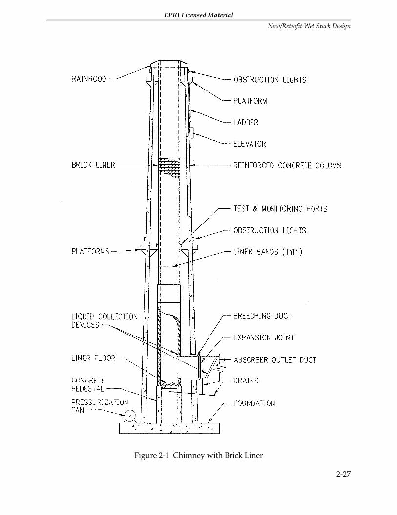
EPRI Licensed Material
New/Retrofit Wet Stack Design
2-27
Figure 2-1 Chimney with Brick Liner
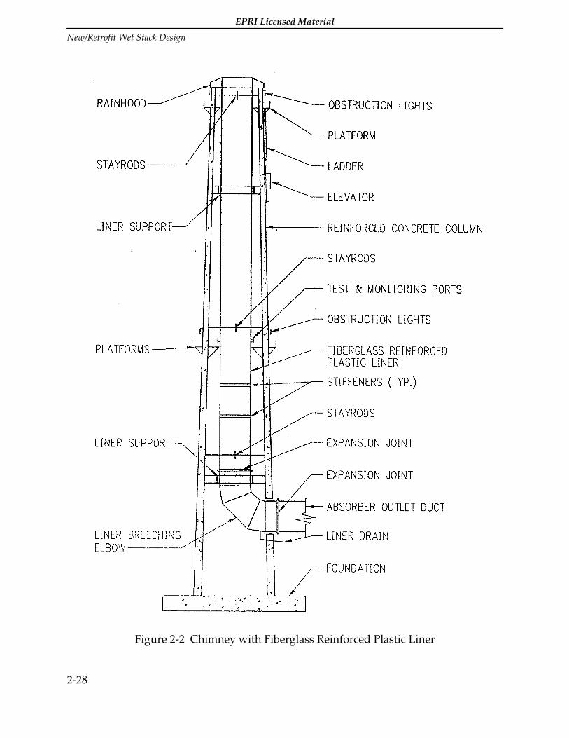
EPRI Licensed Material
New/Retrofit Wet Stack Design
2-28
Figure 2-2 Chimney with Fiberglass Reinforced Plastic Liner

EPRI Licensed Material
New/Retrofit Wet Stack Design
2-29
Figure 2-3 Chimney with Metal Liner Typical for Allloy, Glass Block or ProtectiveCoating Liner System

EPRI Licensed Material
New/Retrofit Wet Stack Design
2-30
For alloy or FRP liners, the conical hopper, sloped floor or elbow material should be thesame material as the liner. Sloped floors in brick liners are supported from an elevatedconcrete support structure or the concrete foundation. Brick liner floors consist ofmultiple layers of materials that provide corrosion and thermal protection to its supportstructure. These floors should be constructed of the following layers of materials: leadpan over asphaltic impregnated felt, acid resistant mortar fill sloped to the drain, and aminimum of two layers of acid resistant brick and mortar. The lead pan should bereturned up the side of the brick liner to provide protection to the wall.
2.2.6.2 Breeching Duct Geometry.
Breeching duct dimensions are typically rectangular, with the long dimension in thevertical direction to minimize the structural effects on the column and liner. It isbeneficial to increase the height to width ratio of the breeching by transitioning thewidth narrower and the height taller as the breeching approaches the liner and bykeeping the floor level. This minimizes the amount of liner cross-sectional area that isinterrupted at the breeching openings. The height (H) to width (W) ratio (H/W) of thebreeching duct opening should be in the 2.5 to 3.5 range for good liquid flow on theliner wall opposite the breeching duct.
For brick liners, the breeching opening width may dictate the diameter of the liner. TheASTM C1298 brick liner design guidelines recommend that the opening width notexceed one half the internal diameter of the liner at the opening elevation.
For tall breeching openings, the vertical edge of opening should be designed to haveadequate stability as a column element. Multiple and single openings under axialcompression should be reinforced or proportioned to fully restore the structuralcapacity of the entire cross-section. Brick liners utilize brick pilasters and alloy linersutilize vertical jamb stiffeners to provide vertical edge stability.
2.2.6.3 Liner Geometry.
Steel, alloy and FRP liners are typically, but not necessarily limited to, plumb orconstant diameters. Several different support methods are available for these types ofliners. For steel and alloy liners, a common arrangement is to support the liner at ornear the base or breeching entry. The liner is supported in compression, and bumpersor stay rods are used to provide lateral support.
Tall steel and alloy liners supported in compression would need to evaluate the cost ofincreased wall plate thicknesses versus providing a second support level near the top ofthe chimney to support most of the liner in tension. An expansion joint would berequired above the lower support to accommodate thermal movements.

EPRI Licensed Material
New/Retrofit Wet Stack Design
2-31
FRP liners are generally supported with the majority of the liner in tension. Supportsare provided at two locations, one near the top and the second near the breeching level,with an expansion joint located above the breeching level.
Expansion joints in wet stack liners are a problem because they tend to collect liquid,resulting in complete liquid reentrainment at the expansion joint cavities. Therefore,expansion joints should be avoided or provided with liquid collectors.
Because of structural considerations to accommodate breeching openings and designloads, brick liners can be plumb or tapered. Depending upon the breeching openingelevation as well as other factors, brick liners can be supported from the stackfoundation, from a concrete pedestal or from a corbelled support in the concretecolumn. Chimneys with breeching openings that are less than 50 feet above thefoundation would probably use a brick liner that is supported directly off thefoundation. Breeching openings that are more than 50 feet (15 m) above the foundationshould consider utilizing a concrete pedestal to support the lining. For tall brick linerswith thick walls at the base, it is generally more economical to use a concrete pedestalfor high breeching entries.
Brick liners in high seismic locations sometimes use a corbel supported liner to reducethe seismic loads. The liner is constructed in short segments that are supported fromconcrete ledges in the chimney called corbels. This method of construction is notrecommended for wet stack applications. Liquid and flue gas leaking through the brickliner can attack the concrete support system. Additionally, it is difficult to pressurizethe annular space areas at each of the corbel sections.
Tennessee Valley Authority's Paradise Station Units 1 and 2 have a stack with a corbelsupported brick liner. In order to add a pressurization system to the stack after thereheaters were taken out of service, an extensive system of ductwork had to be erectedon the exterior of the chimney. This pressurization system was incorporated to protectthe corbels and the concrete column from flue gas liquid that could leak through thebrick liner. Further information on this pressurized corbel supported chimney liner canbe found in Reference (7). These two units also have duct and stack liquid collectorsinstalled.
2.2.6.4 Choke Geometry.
Stacks that operate with a low discharge velocity sometimes have problems withdownwash or insufficient plume rise. To reduce these problems, a choke can beincorporated at the top of the liner. Chokes are designed to increase the gas exit velocityby decreasing the discharge diameter. It must be noted that the use of a choke, whichconstitutes a "dispersion technique" under EPA stack height regulations, cannot resultin a relaxation of the emission limitation for the facility. Chokes will increase draftlosses and the fan pressure rise should be selected accordingly. Chokes will also cause a
EPRI Licensed Material
New/Retrofit Wet Stack Design
2-32
positive pressure inside the liner and increase the leaching problems with a brick liner.Chokes can be fabricated from corrosion resistant alloys and FRP. If a choke is installedon a wet stack liner, a choke liquid collector will be needed at the top of the choke,because the choke discharge velocity usually exceeds the liquid reversal velocity for thechoke surface material. The choke surface material for recent choke designs is nickelalloy or FRP, even for brick liners.
An Alloy C276 choke was installed on the top of the brick liner at the Bailly StationUnits 7 and 8 stack. An Alloy C276 liquid collection ring was installed around theexterior of the choke to collect the liquid from the choke surface and drain it to theground level. The stacks at Allegheny Power Services' Mitchell Station Unit 3 and atD.B. Wilson Station Unit 1 have brick liners with brick chokes. The stack at MichiganSouth Central's Endicott Station Unit 1 has a borosilicate glass block liner with a chokefabricated from Alloy C22. Based on discussions with plant personnel and the industrysurvey data, stack liquid discharge has not been a problem at these plants.
2.2.6.5 Multiple Versus Single Liners.
Stacks can be designed to enclose a single or multiple number of liners. Each liner canalso be designed to accommodate a single or multiple number of operating units.Economics, plant layout, ductwork layout, and the need to perform maintenance duringunit outages should be considered when evaluating these options. The capital cost for astack with multiple liners is typically less than the combined costs of several stacks withindividual liners. However, this savings is partially offset by the increased costsassociated with a larger foundation, longer ductwork, and possibly larger pressure riseinduced draft fans.
Building a single large diameter liner to serve multiple units is not recommended,because if maintenance needs to be done on one unit, both units need to be out ofservice. Multiple units operating within a common liner also cause additional designconsiderations such as gas temperature differentials, variable flow rates, andcontinuous emissions monitoring system certification. The continuous emissionsmonitoring systems for a liner serving multiple units would need to locate itsequipment in the upstream ductwork rather than in the stack, in order to monitorreadings from individual units. Another concern would be with one unit off line, lowload operations would result in a low exit velocity causing potential downwashproblems. For good liquid collection, a one breeching duct per liner designconfiguration is recommended. The combination of flows from multiple units into asingle flue may qualify as a "dispersion technique" under EPA stack height regulations.The emission limit for the units may not be influenced by the effect of any dispersiontechnique.

EPRI Licensed Material
New/Retrofit Wet Stack Design
2-33
2.2.6.6 Downwash Guidelines.
The parameters that affect plume downwash and the consequences of allowing plumedownwash are discussed in Section 1 of this Report.
Momentum Ratio (MR) is the ratio of vertical plume momentum to horizontal windmomentum:
MR = (ρV2)flue gas/(ρV2)wind)
MR is the most important fluid dynamic force ratio that affects plume downwash. Theindividual parameters within this ratio have the following importance for wet stackplume downwash:
1. Flue gas density (ρflue gas) is almost constant for saturated flue gas at about 0.066lb/ft3 (1.06 kg/m3) at sea level ambient pressure. Reheat will decrease this value by 5to 10 percent.
2. Wind density (ρwind) varies with ambient temperature at sea level ambient pressurefrom 0.090 lb/ft3 (1.44 kg/m3) at -20 degrees F (-29C) to 0.071 lb/ft3 (1.14 kg/m3) at100 degrees F (38C), about a 25 percent spread.
3. Reduced ambient pressure at high elevation plants reduces density by 10 percent to20 percent but it changes both density values by the same amount.
4. The flue gas discharge velocity (Vflue gas) is at the highest stack elevation and is set bythe liner or choke discharge diameter and the low load to high load flue gas volumeflow rate. This value can be anywhere in the range from 20 fps to 120 fps (6-37 m/s)for a wet stack plume discharge.
5. The wind velocity magnitude, direction and frequency of occurrence variessignificantly across the country but this information is usually available at weatherstations and airports located near existing or new power plant sites. The informationneeded is what is usually referred to as the "windrose" data in graphical or tabularform which includes:
• Wind velocity and frequency as a function of direction (22.5 degree sectors).
• The cumulative data is usually supplied on a yearly basis, but the data is alsoavailable on a monthly basis (or more frequently) if time of year is important.
When reviewing the wind data, a judgement must be made when selecting a worstwind magnitude and cumulative frequency of occurrence to eliminate unusuallyhigh windstorms of short duration that seldom occur.
Items 1, 2, 3, and 5 can usually be set for a specific plant site. Item 4, the flue gasdischarge velocity, must then be selected to satisfy the requirements for:

EPRI Licensed Material
New/Retrofit Wet Stack Design
2-34
• Plume downwash.
• Plume dispersion.
• Liquid collection and drainage.
For plume downwash considerations, design decisions must be made concerning theextent of allowable downwash and the cumulative amount of time that downwashoccurs over the period of a typical year. Factors to be considered are:
• Unit load schedule versus time.
• Windrose data.
• Geometry of the top of the stack.
• Extent of downwash allowed:
— None (may not be achievable).
— On liner extension.
— On roof or hood.*
— On stack shell.
• Cumulative time of downwash (per year):
— Zero (may not be achievable).
— Less than 2 days (0.5 percent).
— 2 to 4 days (0.5 to 1 percent).*
— 4 to 8 days (1 to 2 percent).
*The extent of downwash and cumulative time of downwash marked are suggestedvalues at which to start the evaluation of downwash and its effect on stack dischargevelocity.
If the resulting stack discharge velocity is unreasonably high, the downwash criteriamay have to be relaxed to allow more downwash and time duration.
A wind tunnel model study of the stack top for a specific plant and geometry isrequired for an accurate evaluation of the extent of plume downwash and cumulativetime of downwash. Presented below are some approximate guidelines that can be usedfor preliminary evaluate the degree of plume downwash expected, and select startinggeometries of the stack top for wind tunnel selection.
The momentum ratio ranges presented below represent a variation from intermittentdownwash, which is nearly continuous for the low momentum ratio, to intermittent forthe larger momentum ratio. Below the lower momentum ratio for each range, thedownwash is continuous. Above the upper momentum ratio for each range, the

EPRI Licensed Material
New/Retrofit Wet Stack Design
2-35
downwash is almost unnoticeable. The following two momentum ratio ranges arediscussed below:
• MR1 - Momentum Ratio range for intermittent downwash to roof or hood.
• MR2 - Momentum Ratio range for intermittent downwash to the shell.
For all stack top geometries discussed below, the stack shell diameter should be as smallas practical to contain the number of liners.
Single Flue Stacks
1. For an angled hood and no liner extension.
• MR1 {{congruent}} 3 to 5
• MR2 {{congruent}} 2 to 3
2. For a flat or angled roof and a short liner extension (extension {{congruent}} 0.5extension diameter).
• MR1 and MR2 are expected to be lower (10 to 20 percent).
Two Flue Stacks
1. For a flat roof plus a liner extension of about one liner extension diameter.
Best wind direction:
• MR1 ≅ 1.5 to 2.0
• MR2 ≅ 1.1 to 1.5
Worst wind direction:
• MR1 ≅ 3.5 to 5
• MR2 ≅ 3 to 4.5
2. For a minimum liner extension of 0.75 extension diameter, the MR values above willremain the same for the best wind direction, but the MR values above for the worstwind direction will rise by 10 to 20 percent.
3. For a taller liner extension of 1.5 extension diameters, the MR values above for thebest wind direction will remain the same, but the MR values above for the worstwind direction will drop by 10 to 20 percent.
4. A chamfered stack top (2 sides) will increase the best wind direction MR valuesslightly (10 to 20 percent) but will reduce the worst wind direction MR values by 30to 50 percent.
Three and Four Flue Stacks

EPRI Licensed Material
New/Retrofit Wet Stack Design
2-36
1. The best wind direction MR values are expected to be similar to single flue stacks.
2. The worst wind direction MR values are expected to be similar to the two fluestacks.
In most locations, there is a prevailing wind direction where the highest wind velocitiesoccur for longer periods of time. For single flue stacks this has no effect on the extent orduration of plume downwash. However, for multiple flue stacks, it will beadvantageous to orient the multiple flue arrangement so that the prevailing wind isaligned with the best wind direction which gives the lowest MR values.
This will result in the lowest cumulative time for plume downwash for a specificcombination of flue gas discharge velocity and stack top geometry.
The plume downwash guidelines can be used to obtain preliminary estimates of thestack top design to limit the extent and duration of plume downwash:
1. Select a plume downwash criteria at a specific unit load.
2. Select a basic stack top design except for flue gas discharge velocity.
3. Obtain the windrose data and select reasonable design wind velocities.
4. Select the appropriate MR guideline value compatible with steps 1 and 2.
5. Calculate the corresponding flue gas discharge velocity, flue gas discharge area andthe preliminary stack top geometry.
6. Compare the results in step 5 to values compatible with good plume dispersion,stack liquid collection and drainage, and construction cost.
7. Repeat steps 1 through 6 until satisfactory results are obtained for all importantcriteria by making appropriate compromises.
The final stack top geometry should be optimized by wind tunnel plume downwashstudies, particularly for multiple flue stacks where downwash minimization isimportant.
2.2.6.7 Annular Space.
Sufficient space should be provided between the inside of the concrete column and theoutside of the liners to allow for inspection and maintenance for the full height of thestack. A minimum annular space of 2'-6"(0.76 m) is recommended. If platforms, laddersand an elevator are located on the interior of the stack, sufficient annular space needs tobe provided for these items. The size of the annular space should account fordifferential movements that may occur between the concrete column and the liner dueto wind, seismic, or thermal expansion. Damage to platforms or the liner may occur if

EPRI Licensed Material
New/Retrofit Wet Stack Design
2-37
sufficient space is not provided. Access and adequate clearance for clean-out doors andcontinuous emissions monitoring equipment also needs to be considered. Ports shouldbe accessible and provide sufficient clearance between the column and liner to insertEPA test probes. To minimize annular space requirements, doors can be provided in thecolumn. Monorails can be used to assist in installation of the probes.
In order to ensure personnel safety, the annular space should be well ventilated,especially when an interior access system is used.
2.2.7 Liquid Collection Devices and Drainage
Saturated gas flow and condensation on the surfaces are normal operating conditionsfor wet stacks. Some mist eliminator liquid carryover and the liquid condensed from thelarge amount of vapor present in the gas result in a higher liquid load in the duct andstack flow passages than with reheat. Liquid collection devices are recommended tocollect the liquid in the outlet ductwork and in the stack before it exits the chimney.Liquid collectors and drains are an important design consideration in a duct/stacksystem for wet operation. The behavior of the gas/liquid flow is described in Section 1,"Sources of Liquid in Wet Stacks" and the guidelines for selecting the duct stackgeometry suitable for wet operation is discussed in Section 2, "Geometry." The generalinformation about the liquid collection system is described here while design anddevelopment tools are described in Section 2, "Evaluation for Wet Operation."
Reference (1) provides a description of typical liquid collection devices. The Wet StacksDesign Guide provides the latest technology regarding liquid collector locations. Thetools used for these new developments are discussed in Section 2, "Evaluation for WetOperation." The successful design and operation of a wet stack liquid collection systemstarts with the mist eliminators and includes all elements of the absorber duct,breeching duct, stack entrance, stack liner and stack discharge. Each element along thegas flow path is important.
The liquid collectors collect all the deposited liquid and condensed liquid from the ductand stack surfaces. The type, size, geometry, and location of liquid collectors areselected to utilize gas shear and gravitational forces to collect the liquid and drain it outof the system before reentrainment can take place.
The actual design and optimization of the liquid collectors is site-specific work, anddepends on the duct-stack geometry, gas velocity levels, and three-dimensional gas andliquid flow patterns. The best liquid collection system has to be optimized for eachspecific unit. A flow model studyshould be performed by an experienced modelingcompany to determine the optimum location and configuration of the liquid collectiondevices. Descriptions of the major liquid collection areas are given in the followingsubsections.

EPRI Licensed Material
New/Retrofit Wet Stack Design
2-38
2.2.7.1 Mist Eliminator System.
The mist eliminator system is the first and most important element of the liquidcollectors in a wet duct stack system. The selection of the best mist eliminators to matchthe absorber and duct design result in reduced liquid load in the duct stack system anda less elaborate liquid collection system. In flue gas desulfurization (FGD) service, thefunction of the mist eliminators (MEs) is to remove entrained scrubbing slurry from theflue gas before it travels out of the absorber into the downstream ductwork and stack.The mist eliminators are located downstream of the absorber spray zones, where theflue gas contacts the scrubbing slurry that removes sulfur dioxide. Slurry content of theliquid carryover can cause solids buildup in the outlet ductwork and stack, highparticulate emissions, and corrosion. The amount of liquid that the flue gas carries intothe mist eliminator will depend on droplet size, the gas velocity, the liquid-to-gas ratio,the washing method, etc.
The amount of liquid droplet carryover into the wet duct stack system from the misteliminators can be minimized by:
1. Selecting the most suitable mist eliminator elements for the operating conditions ofthe installation.
2. Using two stage mist elimination.
3. Using gas velocities with a safe margin under the critical reentrainment velocity forthe mist eliminator blades selected.
4. Achieving a sufficiently uniform velocity profile into the second stage misteliminator to keep all regions below the critical reentrainment velocity.
5. Selecting effective washing techniques and procedures to prevent solids buildup onthe mist eliminators without entraining wash spray in the gas flow.
6. Establishing inspection and maintenance procedures for the mist eliminators.
7. Maintaining good pH control to reduce solid precipitation in the mist eliminators.
Reference (3) describes all essential aspects of the mist eliminator design, application,operation, and maintenance necessary for an effective mist elimination system. Themeasured laboratory performance of several commercially available mist eliminators isalso furnished in this reference.
2.2.7.2 Ductwork.
Since liquid deposition and condensation take place in the ductwork as well as in thestack, it is important to do as much liquid collection in the ductwork as possible. Layoutof the ductwork geometry, sizing of the ductwork, liquid collection devices andsufficientdrainage should be considered in the design of the ductwork connecting the

EPRI Licensed Material
New/Retrofit Wet Stack Design
2-39
absorber and the stack. Liquid collection is easier in horizontal gas flow ducts than inthe vertical flow stack liner. An effective liquid collection system installed in theductwork will result in reduced liquid load for the stack liquid collectors.
Absorber towers often have a 90 degree turn at the top of the absorber where entrainedfine droplets deposit on the ceiling or on the vanes if equipped with turning vanes.Turning vanes promote deposition and reduce pressure losses at the same time.Therefore, the cost of the turning vane addition can be justified in most cases. Liquidcollectors should be provided on the vanes to collect the liquid and preventreentrainment.
In straight rectangular duct sections simple sidewall collectors and slanted or V-shapedceiling collectors can be used. Figure 2-4 shows generic examples of ductwork liquidcollectors. The actual details are a function of the ductwork geometry, gas velocity, andliquid loading in the gas flow. These collectors are usually L-shaped cross sections andtheir sizes range from 2" x 2" to 6" x 6" (0.05m x 0.05m to 0.15m x 0.15m) depending onthe duct geometry and gas velocities.
Liquid collectors located on the outside wall are used downstream of 90 degree ductbends Turning vanes and baffles can be added to the bends to promote deposition;when equipped with liquid collectors, they provide additional liquid collection in theduct system.
Round ducts have to be equipped with liquid collectors also. Usually fewer collectorelements are needed but they are more difficult to install because they have to followthe curved surface contour in round ducts.
Internal bracing in rectangular ducts should be avoided. Bracing provides additionalimpingement surfaces and reentrainment sites. If internal bracing has to be used inbreeching ducts, diamond shaped bracing is recommended for its better drainingqualities.
Liquid collectors in the breeching duct represent an effective last collection stage beforeentering the liner. Good liquid collection in the ducts means reduced liquid load on thestack.
Liquid collects and drains in the duct expansion joint cavities on the side walls but theliquid reentrains at the expansion joint cavity in the ceiling. Commercially suppliedduct expansion joints collect some liquid in the cavities but suitable additions to theexpansion joints are needed for good liquid collection. Properly designed plates andpartial covers can improve the liquid collection in the expansion joints. They should beused when the complete liquid collection system needs this additional increment ofimprovement.

EPRI Licensed Material
New/Retrofit Wet Stack Design
2-40
Guillotine dampers are better for wet ducts than louver dampers because they presentsmaller surface areas for liquid deposition and the lower reentrainment rate representsa smaller liquid collection problem in the duct. The liquid droplets deposit on dampersurfaces in the gas stream and usually reentrain from these surfaces as larger droplets.
The absorber can be placed directly under the liner in the bottom of the chimney,however that will require a larger chimney shell. The only ductwork is a transition fromthe absorber discharge to the liner inlet. Liquid collection is required in the transitionduct to prevent liquid reentrainment.
2.2.7.3 Stack Liner and Choke.
The stack liner opposite the breeching duct generally receives more liquid depositionthan any other area downstream of the absorber. Therefore, the liquid collection in thestack entrance zone is critical. As liquid enters the liner, it is deposited on the liner wallopposite the breeching. Gas flow patterns then tend to drag the liquid around the insidecircumference of the liner back to the breeching. A liquid collector added around thebreeching prevents this liquid from being reentrained into the gas stream. Figure 2-5shows generic examples of stack and choke liquid collectors. The size, shape, andlocation of these liquid collectors are functions of the liner material, stack geometry, gasvelocity, and liquid loading. Typical liquid collectors are a gutter above the breechingduct and two flow guides on the liner along the sides of the breeching entrance. Liquidcollected in the liner entrance should drain to the liner floor or hopper where it can beremoved by a drain. A full circumference liquid collector ring may be needed in someinstallations in conjunction with the liner entrance liquid collectors.
If the maximum projection or offset between bricks on the interior surface of the linerexceed 1/8 inch (0.003m), then partial reentrainment may occur on the wall opposite thebreeching duct. Different methods can be used to reduce the surface discontinuities inthis area on the brick liners, such as careful construction of the bricks over this area. Theremoval of the protruding mortar from the joints makes the surface smoother for liquidflow. A coating used over the brick provides a smoother surface. A smoother targetwall can be installed over the selected brick area where reentrainment may take place.
Brick surface tolerance on the inside face of the liner at NIPSCO's Bailly Station waslimited to 1/8-inch (0.003m). During construction of the acid brick liner at NYSEG'sKintigh Station, the contractor was directed to avoid locating lateral offsets in the brickliner on the wall opposite to the breeching duct within 100 feet (30 m) of the breechopening and to remove all loose mortar, particularly in this critical reentrainment area.
The horizontal weld beads on alloy liners can cause a local liquid reentrainment in thestack above a velocity of approximately 40 fps (12 m/s). The height of the weld beadshould be the minimum possible and not exceed the standard for good weld quality of1/8-inch (0.003m). To achieve liner design velocities for smooth metal, horizontal weld
EPRI Licensed Material
New/Retrofit Wet Stack Design
2-41
beads must be ground flat and smooth. If the shape of the weld bead is gradually risingand falling, liquid reentrainment is reduced. Similarly, the rings of FRP liners should beglued together with material mostly on the outside of the liner. Only minimum inwardprotrusion with smooth transitions is recommended. Pennguard block liner seamsshould be made as smooth as possible by removing the excess adhesive protrudinginside the surface during construction.
The liquid condensing along the stack liner flows down on the surface when liner gasvelocities are below the liquid reversal velocity. This liquid reentrains at the expansionjoints by the gas flow in the expansion joint cavity. Most of the reentrained dropletsdischarge from the stack. For this reason, the liner suspension should be designed sothat liner expansion joint is not needed. If an expansion joint is installed, it should beequipped with liquid collectors especially designed for expansion joints. Onlylaboratory flow modeling can be used to design and develop liner expansion jointcollectors that are effective at all operating loads of that unit.
A choke designed for the top of the liner increases the stack discharge velocity thatusually exceeds the liquid film flow reversal velocity for the choke material. Therecommended choke material is solid alloy for alloy and brick stack liners. FRP chokeshould be used with FRP liners. Liquid reaching the top of the choke is discharged andfalls to the ground within the near vicinity of the stack. Chokes for a wet stack have tobe equipped with an effective liquid collector to prevent this liquid discharge.Horizontal weld beads should always be ground flat and smooth on the inside of thechoke surface.
Allegheny Power Services' Mitchell Station Unit 3 had a model study performed andinstalled all of the recommended liquid collection devices. The liquid collection devicesare working well and have had no problems with stack liquid discharge after 12 yearsof operation. Louisville Gas and Electric's Trimble County Unit 1 has three liquidcollectors in the 26-foot diameter absorber outlet duct that consists of 4-inch guttersaround the inside of the duct. Three drains in the absorber outlet duct which drain backto the absorber building sump. At Trimble County, the stack exit velocity is high andresults in some localized stack liquid discharge. However, since the plant is located outin the country, there have been no consequences due to stack droplet discharge.Louisville Gas and Electric's Cane Run Units 4, 5, and 6 had model studies performed toevaluate liquid collection. All of the liquid collection devices recommended by themodel study were installed on Unit 5. On Unit 6 most of the recommendations werefollowed. A baffle wall was installed in the chimney inlet and a sloping floor and trenchwere installed in the bottom of the liner to drain off liquid. Cane Run does not have anyreported problems with discharge.

EPRI Licensed Material
New/Retrofit Wet Stack Design
2-42
2.2.7.4 Chimney Roof (To Prevent Icing).
Stacks with a roof instead of a rainhood are relatively flat to serve as a walking surface.Because of the tendency for liquid fallout accumulation in this area, discharged liquidand rain water sometimes freeze on the roof during cold weather. Ice formation at drainlocations may prevent liquid from entering the drains. In order to prevent thisoccurrence, roof slopes should be sufficient to prevent liquid from pooling and multipledrains are recommended. The roof drain should be separate from the liner or chokeliquid collector drains because of pressure differences and different disposal methods.
2.2.7.5 Drains.
The collected liquid has to be drained out of the duct-stack system. In general, drainscan be installed in the horizontal absorber outlet ducts, duct expansion joints, stackfloor, liner expansion joint collectors, and choke collectors. The preliminary wet stackdesign should plan an adequate drainage system by considering the drainage needsdiscussed in thissection. The final number of drains needed and their optimum locationare specified as one of the results of the laboratory flow modeling.
The absorber duct drains are most effective if a trench or scupper is installed across theduct in the floor with a drain. The drains, if installed in duct expansion joints, areselected based on local conditions. Sloping the floor of the absorber ducts eliminateswater puddles after shutdown when all the liquid from the walls drains to the floor.The sloping floor does not alter the liquid flow on the duct floor during operationbecause the gas shear dominates the liquid motion on the floor.
Duct floor drains may be required where liquid pools can build up and waterreentrainment from the pool may take place.
The stack floor drains often require a wire cage or equivalent over the inlet to preventplugging by flaking solid scale.
The stack liner expansion joint collector drains and the choke liquid collector drainshave to be individually pressure-balanced with siphons or drain pots. These drainsconnect points of different static pressure levels inside the liner.
Since the liquid is acidic, the material selection for the drain line and the means of finaldisposal must be evaluated. FRP pipe is commonly used for wet FGD drain lineapplications. FRP pipe provides good chemical resistance to these acids and is moreeconomical and more readily available than stainless steel or nickel alloy pipes. Drainlines are sized to prevent pluggage and ease of cleanout. The six to eight inch minimumdiameter drain pipes used have much larger liquid flow capacity than needed. Seal potsor siphons should be provided as needed, to prevent air inflow under negative pressurewhich would prohibit liquid discharge through the drain line. Different drain lines can

EPRI Licensed Material
New/Retrofit Wet Stack Design
2-43
be connected only if the static pressure at the flue gas end is the same; in other casespressure seal pots are required. Chimney drain lines should use pipe crosses, tees, orwyes with bolted blind flanges for clean out. The drain lines should slope withouthorizontal sections to reduce pluggage. Access to cleanout connections should beprovided.
Outdoor FRP drain lines should have a steep enough slope to prevent freezing. Forlong, relatively flat horizontal runs of drain line, the pipe should be heat traced andinsulated.
2.2.7.6 Disposition of Collected Liquids.
The liquid discharging from drain pipes has to be recycled into the FGD system orproperly disposed of. The following liquid disposal methods should be considered:
2.2.7.6.1 Waste Sump or Return to Process
Liquid collected from within the ductwork or stack can be routed to the waste sump orreturned to the FGD system process. Liquid routed to the waste sump does not reenterthe process and is disposed of. Liquid returned to the process can be routed to theabsorber reaction tank. Liquid returned to the process may be of sufficient volume andpH level that it could change the operational characteristics of the FGD process.Thevolume and pH of the liquid returned to the process should be considered tocompensate for any operational changes that may be needed.
2.2.7.6.2 Single Versus Multiple FGD Modules
A single stack liner that serves multiple FGD modules may produce large volumes ofliquid for disposal. Drainage pipe diameters need to be sized accordingly. If the liquidcollected from multiple FGD modules is returned to the FGD process, the volume ofliquid may be too large to be returned to a single FGD module without significantchanges to its operational characteristics.
2.2.8 Operating Conditions
The design of the stack liner and its components is based primarily on the range of fluegas conditions at the stack inlet. The stack operating conditions affect the selection ofthe liner's materials of construction, the liner diameter and the design of the annuluspressurization system and the liquid collection devices.

EPRI Licensed Material
New/Retrofit Wet Stack Design
2-44
The stack inlet flue gas and ambient air conditions that can affect stack liner designinclude:
• Temperature.
• Pressure.
• Moisture content.
• Flue gas composition.
• Flue gas flow rate.
• Flue gas liquid content.
These stack inlet conditions are a function of the fuel burned in the boiler, the operationof the boiler, the boiler load, air leakage into the system, heat loss from the system, andthe wet FGD System. The following sections provide discussions of how theseconditions are factored into a wet stack design.
2.2.8.1 Flue Gas Calculations.
Flue gas calculations are needed to predict the range of operating conditions for a wetstack design. Normal design procedure uses combustion calculations to estimate therange of gas conditions at the FGD inlet and an energy balance to estimate the range offlue gas conditions at the stack breeching entrance. The first step is to calculate the gasconditions at the FGD inlet using the following inputs:
• The desired range of boiler loads and corresponding heat inputs.
• The fuel heating value and composition.
• The excess air at the boiler outlet.
• The air leakage (upstream of the ID fans) into flue gas flow in the air preheater, gasducts and other equipment operating below atmospheric pressure.
• The flue gas outleakage from a pressurized boiler to the FGD inlet or downstreamfrom the ID fans.
• The flue gas temperature and pressure at the inlet to the wet FGD absorbers.
• The plant barometric pressure.
• The absolute humidity ratio of the ambient air.
Using the previous inputs, the combustion calculations result in the following outputs:
• Gas composition and molecular weight.
• Density.
• Mass flow rate.

EPRI Licensed Material
New/Retrofit Wet Stack Design
2-45
• Specific heat.
• Saturation temperature.
These outputs are then used with the following inputs for the FGD absorber energybalance:
• Air inleakage and flue gas outleakage, if any, from the absorber inlet to the stackinlet.
• Flue gas pressure at the stack inlet.
• SO2 removal efficiency.
The outputs of the absorber energy balance define the remaining gas conditions at thestack inlet:
• Gas composition and molecular weight, including the addition of water vapor andthe removal of SO2 (and the addition of CO2 if limestone reagent is used and thereaction tank is integral to the absorber module).
• Gas density.
• Mass flow rate.
• Specific heat.
2.2.8.2 Temperature.
The flue gas and ambient air temperature ranges need to be determined. Thesetemperatures affect the design of a wet stack. When a wet FGD system is used with acoal-fired boiler, the saturated flue gas temperature at the absorber outlet usuallyranges from 120 degrees F to 130 degrees F (49-54° C). For a specific plant the saturationtemperature can be estimated for a range of boiler loads and fuels using the calculationprocedure described in the previous subsection, "Flue Gas Calculations."
For a typical bituminous coal, either of the following variations in FGD inlet conditionswould result in approximately 5 degrees F (3° C) increase in FGD outlet gastemperature:
• 50 to 60 degrees F (28-33° C) increase in inlet gas temperature.
• 2.0 to 2.5 percent by volume increase in inlet gas moisture content.
Other factors affecting the temperature of the gas entering the stack could include thefollowing:
• Barometric pressure.
• Heat loss in the ductwork from the FGD absorber to the stack.

EPRI Licensed Material
New/Retrofit Wet Stack Design
2-46
• Temperature rise through an induced draft fan if located downstream of the FGDabsorber.
• Subcooling of the gas below the adiabatic saturation temperature if the scrubbingliquor is not recirculated. For example, a once-through system using sea water as thescrubbing liquor would cool the gas by an amount equal to the heat gain by the seawater.
• Any other method of subcooling, such as a condensing heat exchanger downstreamof the absorber.
• Reheat, if used.
For a conversion from heated to wet stack operation, the range of absorber outlettemperatures should be obtained from existing FGD operating data. For design of anew plant or for retrofit of an FGD system at an existing plant, the range of FGD outlettemperatures should be estimated using flue gas calculations described in Section 2. Forplant elevations at or near sea level, the saturation temperature may also be estimatedusing a standard pressure, high temperature psychrometric chart for air.
The ambient air temperature design range can vary from -20 degrees F to 110 degrees F(-29 to 43°C) depending on season and plant location. The atmospheric temperature hasa significant affect on the stack effect and the flue gas pressure in the stack, relative tothe ambient pressure outside the stack and in the stack annulus. The temperature rangenoted above produces anambient air density change of +/- 13 percent about standardambient temperature of 68oF (20°C). The coldest ambient air temperature within thedesign range will increase the rate of condensation inside the stack liner, requiring thatthe liquid be collected and drained out of the stack.
2.2.8.3 Pressure.
The total and static pressure of the flue gas inside the stack is a function of thefollowing:
• Ambient temperature and barometric pressure.
• Total pressure losses in the stack entrance.
• Total pressure frictional losses through the liner.
• Total pressure losses across expansion joints, corbel joints, and other stack linerbreeching openings, expansions or contractions.
• Pressure variation with height (stack effect).
• Static pressure changes across area expansions or conical contractions and chokes.
The total (PT) is the sum of the static (PS) pressure and the gas velocity head (VH) at thesame duct or stack liner cross section.

EPRI Licensed Material
New/Retrofit Wet Stack Design
2-47
P P VHT S= +
Total pressure loss from the stack breeching duct to the stack discharge plume is thevalue needed for determining the ID fan requirements for the stack. The maximumdifferential static pressure between the flue gas and the stack annulus at the sameelevation is the pressure needed to select the fans for the annulus pressurization withbrick stack liners.
The combination of these total pressure losses, static pressure changes, and ambientpressure and temperature changes can result in the following:
1. Fan total pressure rise requirements of +2 to +4 inches w.c. (0.5 to 1.0 kPa) and fluegas pressures higher than ambient pressures for:
• Highest ambient temperature within the design range.
• Highest barometric pressure within the design range.
• High choke discharge velocity (110 fps (34 m/s)).
• Moderate stack liner velocity (50-60 fps(15-18 m/s).
2. Fan total pressure requirements of 0 to -2 inches of water (0 to -0.5 kPa) and flue gaspressures lower than ambient pressures for:
• Coldest ambient temperature within the design range.
• Lowest barometric pressure within the design range.
• No discharge choke.
• Low stack liner velocity (40-50 fps (12-15 m/s)).
Calculations for a specific stack, geographic location, and boiler load range can becarried out. The most recent issue of the American Society of Heating, Refrigerating,and Air-Conditioning Engineers (ASHRAE) Handbook, Fundamentals, Chapter 32,Duct Design, provides a detailed discussion of the calculations needed.
2.2.8.4 Stack Effect.
The stack effect is the hydrostatic pressure difference between the inlet and the top ofthe stack. This is due to the lower density of the heated gas in the stack compared to thedensity of ambient air. Therefore, the stack effect is calculated by multiplying thedensity difference of the gas in the stack and the ambient air with the height of thestack. Net stack draft is the operating pressure at the inlet of the stack liner and iscalculated by subtracting the fluid friction and exit losses from the stack effect.
For wet stack design the worst case conditions are the maximum stack gas flow rateresulting in the highest friction loss in combination with the hottest and most humid

EPRI Licensed Material
New/Retrofit Wet Stack Design
2-48
ambient conditions. These conditions can normally be expected to produce a positivegas pressure at the stack inlet. The stack effect at worst case conditions is generally only0.2 to 0.3 inches w.c. (0.05-0.07 kPa) for wet stack operation, a small amount comparedto the friction and exit losses at full load.
2.2.8.5 Stack Flow and Density.
The flue gas volumetric flow rate in the stack liner is calculated from the flue gas massflow rate divided by the flue gas density. The range of flue gas mass flow rates areestimated using the calculations described above.
To determine the maximum design mass flow rate, conservative values for the inputs tothe flue gas calculations should include the following:
• Maximum coal burn rate.
• Lowest coal heating value.
• Maximum allowable excess air leaving the boiler.
• Maximum expected air leakage rates.
• Minimum expected flue gas leakage rates.
However, the worst case design volumetric flow rate cannot exceed the head/flowcapacity of the induced draft fans for retrofits.
The worst case design mass flow rate and the nominal design mass flow rate with usualsafety factors should be compared and the stack design should be evaluated at bothconditions, as well as partload conditions.
The flue gas density is directly proportional to the barometric pressure and the flue gasmolecular weight, and indirectly proportional to the flue gas Rankine temperature (460+ degrees F). The approximate value of saturated flue gas density at the stack inlet forsea level conditions is about 0.067 lb/ft3 (1.07 kg/m3). For the three parametersmentioned above, the flue gas density will change as follows:
• Temperature - A 6 degree F (3°C)change in flue gas temperature causes about 1percent change in density.
• Barometric Pressure - For plants at high elevation, the flue gas density decreasessignificantly (-15 percent at 4400 feet (1341 m)). Atmospheric pressure changes dueto weather can cause a +/- 10 percent variation around the average local ambientpressure.
• Flue Gas Composition - The flue gas molecular weight due to combustion andsaturation changes only a small amount from air, usually to a smaller value. Theaffect on density is usually less than 5 percent.

EPRI Licensed Material
New/Retrofit Wet Stack Design
2-49
All of these individual effects could combine in a reduced density direction.
The range of flue gas volumetric flow rate in the stack liner will be used to:
• Calculate flue gas velocity at each different cross sectional area in the stack system.
• Revise the sizes for the flue gas flow passages for satisfactory liquid deposition,collection, and drainage if needed to achieve acceptable velocity levels.
• Select laboratory model test conditions to develop liquid collectors and drains forthe stack system.
• Estimate pressure losses that are proportional to flue gas velocity head.
2.2.8.6 Moisture and Liquid Content at Stack Inlet.
All of the water vapor content of the stack inlet flue gas flow comes from the absorberoutlet where the flue gas is saturated. The liquid content of the stack inlet flue gas flowcomes from the following sources:
• Mist eliminator droplet carryover, which consists of very small drops (<10 µm) thatnever contact a mist eliminator blade and larger droplets that reentrain from themist eliminator blades, structure or solid buildups.
• Condensation on the duct surfaces upstream of the stack inlet, which adds liquid onthe duct surfaces.
• Deposition of droplets on duct surfaces, vanes, baffles and structure, which removesdroplets from the gas flow stream.
• Reentrainment of droplets from duct surfaces, vanes, baffles, and structure, whichadds large droplets to the gas flow stream.
• Installation of liquid collectors on duct walls and ceilings, vanes, baffles, andstructure, which collects liquid from these surfaces and guides the liquid to the ductfloor of stack bottom drains for removal from the duct stack system.
The geometry of the ducts between the absorbers and the stack inlet, the amount ofvanes, baffles, and liquid collectors in the ducts, and the effectiveness of the misteliminators and duct liquid collectors will determine the amount of liquid, drop sizes,and distribution of liquid in the stack breeching duct at the stack inlet.
For a detailed discussion on the effectiveness of mist eliminator systems, refer toReference (3). To maintain effectiveness, it is very important to keep mist eliminatorsclean by washing to prevent sludge buildup. Some recommendations for washing misteliminators include:
• Use fixed grid spray systems.
• Use high quality wash water.

EPRI Licensed Material
New/Retrofit Wet Stack Design
2-50
• Have a frequent wash cycle. (Thirty second duration every 30 to 60 minutes.)
• Wash the upstream sides of each mist eliminator module at a minimum.
• Provide wash coverage of 180 to 200 percent to ensure adequate overlap of adjacentspray patterns.
• Use a nozzle to mist eliminator spacing of 2 to 3 feet (0.6-0.9 m).
To achieve and maintain duct liquid collector effectiveness between the absorber andthe stack inlet:
• Use a physical laboratory flow model to develop and optimize the vanes, baffles,and liquid collectors.
• Carefully inspect the installed geometry before FGD system start-up to insurecorrect installation.
• Inspect the duct system after about 4 months operation to evaluate liquid flowpatterns on the surfaces and at liquid collectors, and to determine the amount ofdetrimental solids buildup.
• After the first inspection, incorporate any obviously needed changes and establish acleaning/washdown schedule for future operation.
2.2.9 CEM System Considerations
CEM system considerations include provisions for field testing, installation and/ormodification of platforms and access systems, and compliance to EPA testingrequirements.
2.2.9.1 Provisions for Field Testing.
EPA regulations specify that a quality control program includes calibrations andcalibration checks for the CEM equipment installed. Provisions for field testing need tobe made not only to meet regulatory requirements, but to provide preventivemaintenance and to ensure proper functioning of the monitoring equipment. It may berequired to cut holes in existing chimney liners and concrete shells in order to get theprobes through. Access into the annulus space must also be considered. For conversionto wet stack operation, flow monitors need to be recalibrated for the revised flowconditions.
2.2.9.2 Platforms and Access Systems.
Extensions to existing platforms may be required to provide access to new portlocations. Existing ports may be reused wherever possible. If ultrasonic flow monitoringis used, an additional platform landing will be required approximately one liner

EPRI Licensed Material
New/Retrofit Wet Stack Design
2-51
diameter above the main testing platform. Modification to existing handrails may berequired at certain locations to provide clearance for the monitoring equipmentenclosure boxes.
To provide continuous access to the monitoring location and personnel safety, anelevator for accessing equipment on tall stacks is advisable. Platform enclosures may beneeded to provide personnel and equipment with weather protection during the wintermonths. For personnel working in enclosed conditions, adequate ventilation should beensured.
2.2.9.3 Testing Requirements.
Minimum testing requirements are satisfied if the EPA siting criteria for port locationsare adhered to, and if no cyclonic or stratified flow conditions exist. The followingrequirements are the same for wet, reheated, or bypass operations.
2.2.9.3.1 No Cyclonic Flow
EPA 40 CFR Part 60, Appendix A, Method 1 states that the flow condition isunacceptable if the average yaw angle is greater than 20 degrees. If potential flowmeasurement problems are significant, it is recommended that a 3-D traverse be done tomore accurately determine the flow characteristics of each unit. These characteristicsmust be discussed with the regional EPA to determine acceptability. If unacceptable, anevaluation of flow straightening must be done. This could include the addition ofstraightening vanes near themonitor location and/or modification of the deflectionplates at the base of the stack. Any modifications would likely require a three-dimensional flow model study.
2.2.9.3.2 Distance Downstream of Breech Entry
According to EPA test methods for gas sampling (EPA 40 CFR Part 60 Appendix A),flow monitors should be located a minimum of eight stack or duct diametersdownstream and two diameters upstream from any flow disturbance. If necessary, twostack or duct diameters downstream and one-half diameter upstream from a flowdisturbance may be employed. The purpose is to make sure flue gas sample dataobtained are accurate enough so that the total emissions can be accurately calculated.
2.2.10 Evaluation for Wet Operation
The preliminary duct and stack design is completed using the component bycomponent guidance of Section 2, "Specific Design Issues." Next, the complete wet duct

EPRI Licensed Material
New/Retrofit Wet Stack Design
2-52
and stack geometry is evaluated for wet operation as an integrated system, where theindividual components operate together as a unit.
The first objective of this evaluation is to review the preliminary duct and stack designas a complete system for wet operation. How well will all the flow passages worktogether as a system from the absorber outlet to the top of the stack, and how suitableare they to be outfitted with liquid collectors to achieve minimum stack liquiddischarge? If improvements are possible through modification to the duct and stackgeometry, are the gains in reduced stack liquid discharge worth the cost of thegeometry changes?
The second objective is to design an effective liquid collection system that is optimizedfor the integrated geometry and for the range of operating conditions and absorbercombinations.
The combined wet duct and stack systems use a variety of design methods. The bestmethods that have been developed are described in the following subsections. Thedesign methods and tools used to achieve these objectives are:
• Preliminary Design Review Based on Experience.
• Laboratory Flow Modeling, 3-D.
• Computer Flow Modeling, 3-D.
• Computer Program Calculations, 2-D.
These are summarized in the first four subsections below.
The subsection on "Comparison of Experimental and Computer Modeling" is anoverview of the basic gas/liquid flow processes that need to be evaluated in a wetsystem using the design tools,and summarizes the usefulness of the experimental andcomputer tools to carry out the evaluation needed.
The last two subsections are a discussion of the system tests and inspections conductedafter the unit is in operation to help identify how well the final duct stack geometry andthe installed liquid collection system are working. If there are wet operation problems,then the tests and inspections can identify the causes and practical solutions.
2.2.10.1 Preliminary Design Review Based on Experience.
The first two steps in Phase II is to perform a component by component design and thenadjust the design for liquid collection requirements. The results of these first two stepsshould be evaluated by a preliminary design review.

EPRI Licensed Material
New/Retrofit Wet Stack Design
2-53
The preliminary duct and stack liner design geometry for new construction must bereviewed to assess how well all individual components will work together as anintegrated system. The second goal of design modifications implemented at this phaseof wet stack design is to make the integrated geometry more suitable for liquidcollection. This review should be based on actual field experience with liquid collectorsdesigned for different power plants. This modified wet duct and stack design is thestarting geometry for the design of the liquid collection devices. It also optimizes gasflow passages by experimental flow modeling. It is important to get the engineer andmodeling company together to review the preliminary design.
2.2.10.2 Condensation Calculations.
A larger portion of the liquid flow on the liner surfaces is due to condensation then todeposition of the droplet carryover from the mist eliminators. The condensation on theliner cannot be measured in a laboratory scale model of the stack. Therefore, analyticalcalculations are required to define the amount of condensed liquid flow rate in thestack.
The basic description of the adiabatic bulk condensation and the thermal wallcondensation processes is given in Section 1, "Sources of Liquid in Wet Stacks." Itdiscusses the methods to predict condensation rates in the duct and the stack andcalculated condensation data for typical sample stacks are presented here.
Liquid condensation occurs continuously on all wet duct and stack liner surfacesbecause the flow gas is saturated and the liner's inside surface temperatures are lowerthan the gas dew point temperature. But the rate of condensation per unit surface areacan vary significantly depending on geometry, materials, temperatures, and windspeed.
The duct and stack condensation rate cannot be measured in experimental flow models.3-D computer modeling can be adapted for condensation calculations, but it is toocomplex and expensive for this essentially two-dimensional process.
A 2-D condensation analysis is satisfactory to calculate the condensation rate thataccounts for stack geometry, mass flow, heat loss, gas psychrometric conditions and theambient atmosphericpressure variation along the height of the stack. Assuming axialsymmetry for the stack, all the variables can be described or calculated as a function ofvertical height with computer programs developed for this purpose as design tools.
A 2-D computer program was used to calculate condensation rates for 22 cases asquantitative examples for this design guide. The authors selected a 550-MW unitoperating with brick, alloy and FRP liners in the same shell as typical choices for a newduct stack design. Figures 2-1 to 2-3 show the geometry of typical stacks.

EPRI Licensed Material
New/Retrofit Wet Stack Design
2-54
Table 2-7 gives the geometric parameters and gas flow conditions for our three samplestacks. The ambient temperature 0 degrees F, 50 degrees F, and 100 degrees F (-18, 10,and 38°C) and wind velocities of 20 mph (9 m/s) and 40 mph (18 m/s) represent typicalconservative conditions for most parts of the U.S. The selected operating variables andthe calculated results are given in Table 2-8. The major conclusions drawn from theresults of these calculations are as follows:
• The bulk condensation in the liner is a function of stack height.
• For brick liners, the pressurizing air leakage through the liner increases the bulkcondensation by additional cooling.
• The wall condensation is directly proportional to the temperature differencebetween the gas and ambient air.
• The liner material does not affect the wall condensation rate significantly becausethe thermal resistance of the liner is a small fraction of the total thermal resistancebetween the flue gas and the ambient air. Figure 2-6 shows the effect of ambienttemperature for eight selected cases.
• The wall condensation may be reduced by a factor of about 6 by insulating theoutside of the alloy or FRP liners with a 2-inch (0.05 m) fiberglass layer. Increasingthe insulation thickness from 2 inches (0.05 m) to 4 inches (0.1 m) will result in asmall reduction in condensation rate. Therefore, more than 2-inch (0.05 m) insulationis seldom required. Insulation does not eliminate the liner condensation but canreduce it significantly.
• A wind speed increase from 20 mph to 40 mph (9-18 m/s) increases thecondensation rate by only a few percent because the convective heat transfer levelsoff above 20 mph.
• Having more than two liners in a shell increases the total wall condensation rate byabout 5 percent. This is mainly due to a higher condensation rate on the linerextension above the shell.
The condensation in the ductwork is primarily thermal wall condensation; adiabaticcondensation (due to pressure reduction with elevation change) is negligible. Therefore,the rate of condensation here is not as important as in the stack, because most of thecondensed liquid andthe deposited droplets can be collected and drained out beforethey enter the stack. The duct condensation rate is calculated either by a 2-D computerprogram or by hand calculation for the various ductwork surfaces.
The results of the condensation calculation are used to design the liquid collectors andto plan for the liquid disposal system.

EPRI Licensed Material
New/Retrofit Wet Stack Design
2-55
The estimated ranges of the liquid flow rates in the wet duct and stack of the typical550-MW unit are listed here. These numerical values help the stack designer to estimatethe amount of liquid flow to be controlled and accounted for in a wet duct stack system:
• Mist eliminator carryover
— The vapor mass flow rate in the saturatedgas stream is rather large. The totalvapor content at saturation temperatures115oF to 130 oF (46-54 oC)is equivalentto a liquid flow rate of 1,100 to 1,800 gpm (250-410 m3/h)
— The fine liquid mist of diameters <10 µmwith high efficiency mist eliminators .3 to 1.5 gpm (0.1-0.3 m3/h)
• Duct wall condensation 1-5 gpm (0.2-1.1 m3/h)
• Stack wall condensation 1-6 gpm (0.2-1.4 m3/h)
• Bulk condensation in the stack 6-8.4 gpm (1.4-1.9 m3/h)
• Deposition of liquid droplets 1-12 gpm (0.2-2.7 m3/h)
• Droplets reentrained from the walls,diameters 20-2,000 µ m 0-10 gpm (0-2.3 m3/h)
• Liquid in drains 2-12 gpm (0.4-2.7 m3/h)
• Stack liquid discharge (a function of theduct/stack design and the effectivenessof the liquid collectors installed) 0-15 gpm (0-3.4 m3/h)
Table 2-7Condensation in Stacks - Selected Typical Program Inputs
Operating Parameters:
Volume Flow Rate of Flue Gas = 1,800,000 acfm
Inlet Temperature of Flue Gas = 130.00 oF
Atm. Press. at Grade Level = 29.92 inHG
Vertical Distance from BreechingDuct Floor to Liner Floor
= 4.00 ft

EPRI Licensed Material
New/Retrofit Wet Stack Design
2-56
Table 2-7Condensation in Stacks - Selected Typical Program Inputs
Liner Material
Breeching Duct: Brick FRP Alloy
Stack Entrance Loss Coefficient = 1.9 0.48 1.9
Breeching Duct Area (ft2) = 720.0 545.0 720.0
Breeching Duct Dimensions = 15'Wx48'H 26'4 3/8"ID 15'Wx48'H
Geometry - Major Internal Dimensions:
Grade Level to Top of Liner = 500.0 '500.0' 500.0'
Number of ComputationalSections
= 4 3 3
Shell Material = Concrete Concrete Concrete
Breeching Duct Floor Elevation Liner ID Liner Thickness Shell OD Shell Thickness Air Gap
======
4.00'29'1 5/8"1'4"45'9 5/8"1'6'
4.00'26'4 3/8"1"45'9 5/8"1'9'3"
4.00'25'2 7/8"5/16"45'9 5/8"1'9'3"
Top of Stack Elevation Liner ID Liner Thickness Shell OD Shell Thickness Air Gap
======
500.0'29'1 5/8"8"37'9"2'6"
500.0'26'4 3/8"5/8"37'9"4'6 1/4"
500.0'25'2 7/8"1/4"37'9"5'1 1/4"
1ft = 0.3048m, 1 in. = 0.0254 m, F = 1.8xC+32, 1 acfm = 472cm3/s, 1in. Hg = 3.39kPa, 1 ft2
= 0.093 m2

EPRI Licensed Material
New/Retrofit Wet Stack Design
2-57
Table 2-8Condensation in Stacks-Calculated Results for Selected Typical Stacks
Conversions: 1 inch=0.0254 m, °F=1.8×C+32, 1 mph=0.447m/s, 1 ft/s=0.305 m/s,1 acfm=472 cm3/s, 1 gpm=0.23m3/h, 1 gpm/ft2=2.4 m3/h/m2

EPRI Licensed Material
New/Retrofit Wet Stack Design
2-58
Figure 2-4 The Effect of Ambient Temperature on Condensation in Selected TypicalStacks
2.2.10.3 Laboratory Flow Modeling.
An experimental gas flow model study is a valuable engineering tool used to evaluatewet operation of the absorber outlet duct and stack system from each FGD module misteliminator to the top of the stack.

EPRI Licensed Material
New/Retrofit Wet Stack Design
2-59
The primary objectives of flow modeling includes:
1. Preventing the discharge from the top of the stack of droplets that are large enoughto reach the ground before evaporation.
2. Investigating the potential for plume downwash and for icing on the stack liner orshell at low ambient temperatures.
3. Providing velocity profile and swirl patterns at the CEM elevation that satisfy EPArequirements.
Laboratory flow modeling provides the following for wet stack design:
1. Design and development liquid collectors experimentally where needed in theabsorber outlet ducts and stack liner entrance region to prevent large droplets fromreaching the stack liner. The collectors collect liquid from duct and stack surfaces,prevent reentrainment, and guide the liquid to locations where it can be drained outof the system. This development work is conducted on a scale model of the wet ductand stack system from the outlet of each absorber to approximately two stack linerdiameters above the top of the breeching duct. Even though the absorber outlet ductregion is not a part of the chimney design, the duct liquid collector designs shouldbe developed here and provided to the owner so that an integrated complete systemof liquid collectors can be developed for the unit.
2. Evaluation the liner material and liner surface discontinuities as produced by theconstruction technique. A laboratory test determines liquid reentrainment anddrainage behavior over the range of operating conditions represented by the rangeof boiler operation and confirms or selects the stack liner design velocity. This stepcan be eliminated if sufficient reliable information already exists for the selectedliner material.
3. Evaluation of reentrainment at liner expansion joints in a laboratory test rig anddevelopment of a liquid collector design to collect and drain the liquid from the linerexpansion joints.
4. Development of the optimum choke geometry, liquid collectors and drains toprevent reentrainment and discharge of large droplets from the top of the choke.
5. Wind tunnel tests that evaluate downwash of the wet plume, which could lead tostack surface deterioration, unacceptable SO2 ground level concentrations, or icingproblems at the top of the stack. The final geometry of chimney cover shape and theextension of the liner will be specified as a result of this work.
6. Modeling of the absorber outlet ductwork, stack liner breeching duct, and stack linerup to two liner diameters above the CEM elevation. This measures the gas velocityprofile and swirl angles for comparison to EPA requirements at the CEM station.
2.2.10.4 Computer Modeling.
The use of computer programs for computational fluid mechanics in general have beenincreasing during the last 15 years. How and where computer programs can provide

EPRI Licensed Material
New/Retrofit Wet Stack Design
2-60
help and information for the wet stack designers is described here briefly. Theapplicable programs can be separated into two categories: 3-D and 2-D computerprograms.
These categories of computer modeling are compared to the laboratory experimentalflow modeling in the following subsections from the wet stack design point of viewonly.
2.2.10.4.1 3-D Computer Programs
These are commercially available programs designed for general three-dimensionalfluid mechanics calculations. These are not ready to be used for wet stack design. Theyneed significant work to set them up for the geometry and flow processes of wet stacks.They have the potential to handle all aspects of the gas-liquid flow in wet stacks, but atthe present stage of development they cannot describe some of the most important wetstack flow processes, such as reentrainment and liquid flow on surfaces with gas flow.Therefore, the complete wet stack analysis with all the necessary details from theabsorber to the top of the stack will not be possible by 3-D computer code in the nearfuture.
The 3-D computer models are useful to calculate steady gas flow patterns in the ductand stack. They are good for major flow patterns, but they become complex and slowrunning programs as small details are included that require larger computers (i.e. flowin expansion joint cavity, flow around trusses, flow near liquid collectors). The 3-Dcomputer models are very good at describing the trajectories of liquid droplets of allsizes and their impact on deposition points in the duct system when combined with thegas flow calculations. These codes can be used to calculate deposition on the choke conesurface with assumed points of droplet origin. Some of the codes come with trajectorysubroutines that yield very detailed quantitative results.
The condensation on the liner of a wet stack could be described by a 3-D computercode, but a suitable condensation subroutine is not available.
Several available 3-D computer codes are written for dispersion modeling only. Thedegree of complexity and accuracy of these codes vary a great deal as they account forthe terrain and atmospheric conditions over large distances from the stack.Computerized modeling verified by field dispersion measurements is the best tool atthis time to predict the plume dispersion process. Plume downwash at the top of thestack could be predicted by an elaborate 3-D computer model but it has not been doneyet.

EPRI Licensed Material
New/Retrofit Wet Stack Design
2-61
2.2.10.4.2 2-D Computer Programs
These programs are specifically written for selected flow processes. Therefore, their useis important and the results are good, but they are limited to one detail of the completewet stack design work.
Special purpose 2-D computer programs can be very useful for providing quantitativeresults in cases where experimental models are not applicable and 3-D codes are tootime-consuming for the objectives. Their use often yields satisfactory results for 2-Dprocesses such as droplet trajectories and deposition, condensation, and fan washing.
2.2.10.5 Comparison of Experimental and Computer Modeling.
Experimental laboratory modeling and computer modeling can help with wet stackdesign. The objective of this section is to provide information for the wet stack designprocess about the capabilities of these modeling techniques. The different flowprocesses important to wet stack design are listed in Table 2-9 and the applicability ofthe modeling methods is identified.
Experimental flow modeling's main advantage is that it can be used for all gas-liquidprocesses of primary importance in wet duct stack systems except the condensationcalculation. It can provide information about the large scale flow patterns as well aslocal details everywhere in the flow passages. It is the only modeling technique thatprovides information necessary for the design and development of the liquid collectionsystem, liquid film flow, reentrainment, liquid flow around liquid collectors and drainflow. It gives a good overall view of all events and the observer can see connections offlow patterns in the entire system.
Experimental modeling's limitation is that it relies heavily on observations; therefore, itis qualitative in many respects of gas-liquid flow evaluation. The value of theexperimental results depends on the experience of the observer. The number of dropletsizes that can be observed for trajectory and place of deposition is limited becauseobservations can differentiate only if they are made with the injection of a mono particlesize spray.
Computer modeling's advantages are: Its results provide a rather large volume ofdetailed and quantitative information. It is very applicable for trajectory calculation,and condensation can be calculated only by computer modeling. It can generate resultseasily for different operating conditions after the first run.
Computer modeling's limitations are: 1) It cannot describe the flow of liquid on thesurfaces as sheared by the gas flow. 2) It cannot model the reentrainment at surface

EPRI Licensed Material
New/Retrofit Wet Stack Design
2-62
discontinuities. 3) It cannot model the gas flow separation and liquid collection aroundliquid collectors.
Based on the present state of wet stack design, the designer can rely primarily onexperimental modeling complemented by computer modeling for condensationcalculation and dispersion modeling.
Table 2-9Basic Tools and Their Applicability for Designing Wet Stacks and Liquid Collectors
Basic Process Studied forWet Stack Design
3D ExperimentalModeling
3D ComputerModeling
2D ComputerCalculations
Three Dimensional Gas OnlyFlow Patterns
Yes Yes No
Droplet Trajectories Yes Yes Yes
Droplet Impingement orDeposition
Yes Yes Yes
Droplet and Film Flow onSurfaces
Yes No No
Droplet Reentrainment Yes No No
Gas and Liquid Flow AroundLiquid Collectors
Yes No No
Condensation No Yes Yes
LiquidFlow Into Drains Yes No No
Wet Fan Washing No No Yes
Scaling and Solid Build Up No No No
Gas Velocity at CEM Level Yes Yes No
Plume Downwash Yes Yes No
Plume Dispersion Yes Yes No
2.2.10.6 Full Scale Field Tests and Inspections.
After the wet stack is placed into operation, the effectiveness of mist eliminators anddownstream liquid collection devices should be tested to verify that design objectives

EPRI Licensed Material
New/Retrofit Wet Stack Design
2-63
have been met. Reference (1) evaluates various methods for carryover measurementsand recommendations for obtaining accurate results.
Effective operation of the liquid collection devices and drainage systems should also beverified during an off-line inspection of the liner system. Gas and liquid flow on theliner and around the liquid collectors can be determined by observing the pattern ofresidue on the internal surfaces. If heavy solids buildup or deposits are found and arecausing stack liquid discharge, necessary improvements can be defined based on thisinspection.
2.2.10.7 Flow Measurements at CEM Level.
Flow measurements can be taken to confirm operational characteristics of the FGDsystem and liquid collection devices. Several of these measurements are required byEPA and are performed as part of the continuous emissions monitoring certificationand testing. Information that can be provided from the CEMS measurements includes:
• Stack gas flow rates at different operating loads.
• Gas velocity levels and yaw angles of the cyclonic flow.
Additional in-place testing at the CEM level can measure the effectiveness of the liquidcollection system. These tests can be performed as needed to establish the liquid flow inthe stack. The following liquid flow measurements are not mandatory tests performedas part of the CEM system; however, they would be beneficial in furnishing several orall of the following information:
• Measurements of entrained droplet size distribution using VDA method.
• Qualitative amount of liquid near the wall by impingement methods.
• Liquid flow direction on wall (up, down or slanted) by observations at the portscovered by plexiglass cover.
• Qualitative droplet sizes, using a suitable impingement probe exposed to the flowfor a few seconds.
Where there is a large amount of entrained liquid, the droplets may interfere with theCEMS velocity and angle measurements. This situation shows that liquid collection anddrainage must be improved even though the stack liquid discharge is acceptable.
2.2.11 Outage Time
Outage time is the amount of time necessary for an existing unit to be out of service dueto repairs, maintenance, modifications, etc. The outage may be due to an emergency(unscheduled) or it may be routine (scheduled). Outage time applies only to an existing,operating unit. Therefore, the designer does not need to consider outage time for a wet

EPRI Licensed Material
New/Retrofit Wet Stack Design
2-64
stack on a new unit. For a retrofit FGD project, outage time is the time it takes to tie thenew FGD system ductwork into the existing ductwork.
Outage time for ductwork tie-ins should be scheduled during a normal maintenanceoutage. For example, during a scheduled two-week outage at Henderson Station 2,portions of the existing Units 1 and 2 ductwork were removed, portions of the new FGDsystem ductwork were installed, temporary power was supplied to the seal air fans onthe new absorber inlet guillotine dampers, and the existing bypass damper linkageswere welded in the open portion. This enabled work to proceed on the FGD systemafter the duct tie-ins had been completed and the units were returned to operation.When the FGD systems are completed, they can be placed into operation by openingthe inlet dampers. Therefore, no additional outage time is required.
Outage time for retrofit wet stacks should be minimized for economic reasons.Depending on unit size, energy demand, loss of revenue, cost of replacement power,etc., outage time can be very expensive. Some examples of outage costs are $70,000 perday for a 440-MW unit burninglocally mined lignite coal to $125,000 per day for a 700-MW unit burning Powder River Basin coal. To minimize the outage time required for aretrofit wet stack project, the ductwork connections or tie-ins should be made during ascheduled maintenance outage.
2.2.12 Cost
Costs for a new or retrofit wet stack are, for the most part, site specific. Budgetary costsfor a new chimney may be obtained from one or more experienced chimney contractors.Chimney liner costs may be obtained from the liner material vendors, fabricators, orchimney contractors. They will need to know basic information, such as stack height,number of liners, liner diameter, liner material, breeching duct size and height abovegrade, etc., in order to develop a budgetary price.
It is important to include material and labor in the installed cost of a liner system. Forexample, an alloy supplier will provide an estimate for the cost of the material.However, the material also has to be shop fabricated and field erected. It is necessary toobtain budgetary pricing from alloy fabricators and chimney contractors in order todetermine the total estimated installed cost of the liner. Cost estimates can also be basedon published data or on similar projects.
The chimney foundation is a fairly small percentage (10 to 13 percent) of the overall costof a brick-lined chimney. Depending on the subsurface investigation, the foundationcan either be supported on soil, piles, or drilled shafts. The foundation requirements aresite specific and the type of foundation element is selected by the engineer. Due to theheight of wet stacks and the weight involved with brick liners, many chimneyfoundations are supported on either piling or drilled shafts. A soil supportedfoundation is typically larger than a pile- or drilled shaft-supported foundation. The

EPRI Licensed Material
New/Retrofit Wet Stack Design
2-65
size of the foundation can be determined by preliminary structural analysis and the costdetermined by using the latest Means Building Construction Cost Data, by contactingchimney contractors for a price, or by comparison with previous projects.
The estimated installed cost of an elevator can be obtained by contacting an elevatorvendor such as Alimak or Champion Elevator. Similarly, budgetary prices forpressurization fans and dampers can be obtained from equipment suppliers.
Cost for various liner materials are included in Table 2-5. A summary of typical materialitems to be included in a cost estimate are provided in the following Table 2-10.
Table 2-10Cost Items for Chimney with Brick Liner
Item
1.Piling and Foundation
2.Chimney Shell
3.Miscellaneous Steel
4.Inlet Duct
5.Brick Liner(s)
6.Pressurization Fans
7.Electrical
8.Elevator
9.Engineering
10.Model Study


EPRI Licensed Material
3-1
3 CONVERSION TO WET STACK OPERATION
3.1 Process That Leads to a Specification
A wet stack conversion project involves changing the operating conditions for anexisting stack from reheated or bypass gas to fully wet scrubbed gas. Eliminating reheator using an existing stack for scrubbed gas on an FGD retrofit project would require awet stack conversion.
In order to develop a bid specification for a conversion to wet stack operation, thedesigner must follow a logical process. This involves evaluating specific design issuesthat are important to wet stack design. The engineering process that leads to a bidspecification for a wet stack conversion project is discussed in this section.
Included in this section of the Wet Stacks Design Guide is a step-by-step process thatleads from the feasibility study to a bid specification. A process flow chart outline isincluded in Appendix E.2 and provides more information regarding the description ofeach major design issue.
Design of a wet stack conversion project may be broken down into two distinct phasesof work:
Phase I - Feasibility Study.Phase II - Design Process.
3.1.1 Phase I - Feasibility Study
The Phase I feasibility study includes the following steps:
1. Address regulatory issues.
2. Define existing plant considerations.
3. Define operating parameters.
4. Review existing design parameters.
5. Evaluate stack height.
6. Evaluate existing stack, liner, and absorber outlet duct.

EPRI Licensed Material
Conversion To Wet Stack Operation
3-2
7. Determine liner insulation requirements.
8. Determine liner alternatives.
9. Establish liner material options.
10. Perform operating conditions vs. liner design compatibility analysis.
11. Select design velocity limit to prevent liquid reentrainment for each candidate linermaterial.
12. Determine impact of liner modifications on existing construction.
13. Perform preliminary economic analysis of liner material options.
14. Select liner material(s) for wet stack operation.
15. Evaluate fan alternatives.
16. Collect baseline performance data.
17. Determine reheat system design requirements.
18. Perform economic analysis of wet stack vs. reheat operation.
19. Select wet stack or reheat operation.
The wet stack decision process needs to include a feasibility study comparing wet stackoperation versus reheat operation. The study should include permit considerations,dispersion modeling, preliminary design choices (such as liner material alternatives),and preliminary economics.
The study should consider the tradeoff between SO2 removal efficiency and velocity/liner material and ground level concentrations. Obtaining an air permit is an importantissue and will determine whether or not a utility can operate with a wet stack. Thefeasibility study should address all considerations necessary to make sure that the wetstack design will work.
One of the biggest factors involved in a conversion to wet stack is the existing liner. Theexisting liner must be evaluated to determine whether or not it is acceptable for wetoperation, whether it needs to be relined or replaced, or, depending on the outage timeavailable, whether it would be more economical to build a new stack. Steps 9 through14 above apply only to the options of relining or replacing the existing stack liner.
3.1.1.1 Identification of Issues (Phase I)
A number of important issues must be addressed during the Phase I feasibility studyfor the design of a wet stack conversion project, including:

EPRI Licensed Material
Conversion To Wet Stack Operation
3-3
• Gas velocity in the liner.
• Chimney inlet considerations.
• Materials of construction.
• Condition of existing chimney and ductwork.
• Code requirements for stack modifications.
• Adequacy of existing chimney foundation.
• Adequacy of existing steel stacks.
• Operating conditions.
• Wet fans.
• Location of opacity monitors.
• Liquid collection devices and drainage.
• Model study testing to minimize pressure loss and optimize liquid collection.
• Evaluation of performance through stack droplet testing.
• Outage time.
• Cost.
3.1.1.2 Evaluation of Issues (Phase I)
During the wet stack Phase I feasibility study phase, several critical issues such as whatthe existing liner is made of, must be evaluated. This will determine whether or not theexisting liner can handle saturated flue gas. If the existing stack is relined, the existingliner support, stack, and stack foundation may need to be analyzed for additional loads.If the existing liner material is acceptable, what will the exit velocity be for wet stackoperation? If the exit velocity is too high, then additional liquid collection devices or alarger diameter chimney liner may be required. Can the existing scrubber performancebe enhanced by organic acid additions to reduce SO2 emissions? This could affectpermitting of a wet stack.
Each key issue identified in the process flow chart outlines what needs to be evaluatedfrom a technical and an economics standpoint, so the wet stack designer can decide howto proceed.
3.1.1.3 Economics (Phase I)
Economic evaluation of a wet stack conversion should include the following factors:
• Capital costs.

EPRI Licensed Material
Conversion To Wet Stack Operation
3-4
• Operating costs.
• Maintenance costs.
• Outage costs.
Capital costs for a wet stack conversion project include the cost of the chimney shell andliner modifications, as well as such miscellaneous items as access platforms, doors,elevator, pressurization system, drain system, protective coatings, electrical, etc. Capitalcosts for a reheat system include the cost of new reheaters, supports, piping, valves,condensate traps, heat exchangers and pumps (for hot water reheaters), controls,insulation, etc.
Operating costs for a wet stack are fairly minor compared to a reheat system. If the lineris constructed out of acid resistant brick, then pressurization fans are required, whichhave an operating cost. Reheat systems typically have high operating costs due toenergy use. A sample calculation of in-line reheat energy costs is shown in Section 2,Table 2-1.
Chimney maintenance costs will vary depending on choice of liner material. Coatedcarbon steel liners have required periodic recoating, whereas Alloy C276 clad linershave required little or no maintenance. Maintenance on brick liners can include repairof cracks, replacement of liner bands, replacement of expansion joints, etc. All chimneyswill require periodic inspection.
Outage time is critical for a wet stack conversion project. The outage costs associatedwith modifying, relining or replacing the existing chimney liner must be included in theeconomicevaluation. Outage costs can be minimized by scheduling the wet stackconversion project to take place during a normal maintenance outage. Outage costs perday will vary depending on time of year (energy demand), loss of revenue, and cost ofreplacement power. Depending on the outage time required to line an existing stack, itmay be more economical to construct a new wet stack and either abandon the existingstack or use the existing stack for emergency bypass.
To compare the cost of wet stack versus reheat operation, the economic analysis isusually based on present value. The number of years considered should be theremaining design life of the unit or FGD system. Initial capital costs, periodic or annualmaintenance costs, and annual energy costs need to be converted to present value inorder to compare the options on an equal basis.
3.1.2 Phase II - Design Process
Table 2-2, which is included in Section 2, describes the design process for a wet stackconversion project. This table provides a brief description of each step of the Phase II

EPRI Licensed Material
Conversion To Wet Stack Operation
3-5
design process, designation of responsibility, and a reference in the guide wherebackground information is provided.
The design process phase essentially takes the feasibility study and turns it into a bidspecification. During this phase it is necessary to establish the design criteria, definechimney liner and inlet duct geometry, perform the flow model study to determineneeded liquid collection devices, and prepare bid specifications and drawings. Severalof the items considered during the feasibility study phase should be revisited orfinalized during the bid specification phase. This includes such items as designparameters, liner, geometry, liquid collection devices, etc.
Detailed design of chimney modifications required for wet stack conversion is normallyprovided by the engineer. However, depending on the in-house expertise of theengineering firm responsible for specifications and modifications necessary to theexisting stack, it may be more cost effective for a qualified chimney contractor toanalyze the existing chimney shell and perform the detailed design of the new chimneyliner or modifications to the existing liner. Chimney contractors have developedcomputer programs specifically for analysis and design of chimney shells and liners.The chimney-related scope of work is typically included in a separate furnish andconstruct type of contract.
3.1.3 Recommendations
The following recommendations may assist the designer in developing a specificationfor a wet stack conversion project:
• Perform a feasibility study comparing wet stack versus reheat. The feasibility studyshould address all specific design issues necessary for satisfactory wet stackoperation. (Phase I)
• Address regulatory considerations first. Permitting is an important issue and willdetermine whether or not a utility can operate with a wet stack. Converting to wetstack operation may affect ground level concentrations. Perform a dispersion modelbased on Good Engineering Practice requirements for stack height. If increasedground level concentrations prove to be a problem, then organic acid additives ormechanical modifications to the absorber could be considered to improve SO2
removal efficiency. (Phase I)
• Evaluate existing liner materials of construction for wet stack operation. If theexisting material is acceptable, then evaluate exit velocity to prevent liquidreentrainment. If a new liner is required, perform a preliminary economic analysis ofliner material options. (Phase I)
• Stacks considered for conversion to wet operation may have been designed beforeincorporation of present day design standards. Modifications required for theconcrete shell and liner should be evaluated in accordance with present day

EPRI Licensed Material
Conversion To Wet Stack Operation
3-6
structural design standards. This may result in additional modifications to thestructure, other than that required solely for conversion to wet operation. (Phase I)
• Modifications to a stack liner may change the loads being applied to the foundation.If foundation loads have changed, an analysis should be performed to confirm theadequacy of the existing foundation and piling. This also applies to situations wherean existing liner may need to be demolished and a new liner installed. (Phase I)
• Base the wet stack versus reheat economic analysis on the present value of costsover the remaining life of the plant or FGD system. Consider capital costs,maintenance costs, operating costs, and outage costs in the economic analysis.(Phase I)
• Perform a flow model study to design liquid collection devices and measurepressure loss through the duct system. Design flow control devices, if needed, tocontrol stack liquid discharge and pressure losses. The flow model study should beperformed by a qualified flow model firm. (Phase II)
• During preparation of bid documents, establish new design parameters, finalizechimney liner and inlet duct geometry, and finalize liquid collection devices. (PhaseII)
The process flow chart for a conversion to wet stack operation is indicated in Figure E-2of Appendix E. The flow chart indicates the step-by-step process that leads to aspecification for a wet stack conversion project.
3.2 Specific Design Issues
This section deals with specific design issues for stacks that are being converted to wetoperation. Background and state-of-the art information as well as guidelines andrecommendations are provided for each issue discussed. The information presented inSection 2 on materials of construction is also applicable to Section 3.
3.2.1 Gas Velocity in the Liner
Stacks that operate under reheat, partial bypass or full bypass generally have beendesigned for a higher gas velocity in the liner than new wet stacks. Operating the stackwet, by eliminating the reheat, the gas velocity decreases, the density increases, whichresult in system pressure loss decreases by 5 to 10 percent compared to the systempressure loss with a reheat temperature rise of 30 to 60 degrees F (17-33°C).
Operating an existing liner that is converted to wet stack operations usually has a gasvelocity in excess of the recommended velocity presented in Table 2-3 for wet liners;this makes liquid collection within the liner more difficult. Existing liners that areconverted to wet operations and have velocities that exceed these recommendationsmay require that the majority of the liquid be collected in the absorber top and absorber

EPRI Licensed Material
Conversion To Wet Stack Operation
3-7
outlet ductwork. The effectiveness of removing liquid via collection devices locatedonly in the absorber top and absorber outlet ductwork should be evaluated. Entraineddroplets may impinge on the liner, form liquid streams; a larger fraction of the liquidmay become reentrained as larger droplets at higher gas velocity. If the wet gas velocityis higher than the flow reversal velocity for the liner, all deposited and condensedliquid will flow upward to the top of the liner and be reentrained there.
If gas velocities in the ductwork are high, liquid collection in the ductwork may also bedifficult and, therefore, the gas velocities in the absorber outlet ductwork should beevaluated. Ductwork for reheated or bypass gas should be sized for 60 feet per second(18 m/s). Ductwork for wet stacks should be sized for 50 feet per second (15 m/s).Critical reentrainment velocities in the ductwork are difficult to determine and are notavailable. Reference (1) provides liquid collection guidelines that can be used in thisevaluation.
If the liner velocity is lower than the range of recommended maximum values, theliquid reentrainment rate is lower and the need for liquid collectors is reduced.
A flow model study should be performed to evaluate liquid reentrainment and liquidcollection in the ductwork and liner, based on the anticipated gas velocities. If adequateliquid collection cannot be accomplished at the anticipated velocities, a new linerand/or ductwork sized for a lower gas velocity should be considered.
3.2.2 Chimney Inlet Considerations
Stacks operating with partial bypass reheat may have separate ductwork entering theliner for scrubbed and bypass gases. Bypass is when the flue gas is routed around thescrubber and is not treated by the FGD system. Partial bypass reheat is when hot bypassgas is used to raise the temperature of the wet flue gas exiting the scrubber. This mixingof gas is normally performed in the ductwork. Conversion to wet stack operationprecludes any bypass ductwork. With all the flue gas entering the liner through thescrubbed gas ductwork, the head capacity of the induced draft fans should be evaluatedfor the increased pressure loss through the system.
Separate bypass ductwork entrances in the liner should be sealed where the ductworkpenetrates the liner. Sealing the opening flush with the interior surface providesimproved gas flow patterns within the liner. It also eliminates the possibility forcorrosion developing in the dead leg of the bypass duct and the liquid reentrainment atthe cavity opened to the damper.
Eliminating reheat may involve changes to the size or elevation of the absorber outletductwork. In such case the openings in the stack and liner may need to be modified oradded. If modification to existing openings or incorporation of a new opening isrequired, the stack and liner should be analyzed to ensure that they are structurally

EPRI Licensed Material
Conversion To Wet Stack Operation
3-8
adequate to accommodate these changes. For example, at Louisville Gas & Electric'sCane Run Unit 5, a concrete sheath was added to reinforce the existing chimney columnand a new opening was cut for the new absorber outlet duct.
3.2.3 Materials of Construction
Materials of construction associated with the existing liner and ductwork should beevaluated for suitability to wet flue gas conditions.
3.2.3.1 Suitability of Existing Liner Material.
An existing stack designed for reheated or bypass gas conditions typically uses a linermade of carbon steel, brick, or FRP with a quench system. Original material selectioncriteria may not have included the corrosive environment anticipated for conversion toa wet stack application.
3.2.3.1.1 Existing Steel Liners
Many existing reheat and bypass liners have been constructed using bare carbon steelplate. This liner material has been used successfully in some bypass or reheatapplications, but is not considered acceptable for wet applications. Carbon steel willcorrode rapidly under wet acidic conditions.
Steel liners with an existing gunite lining are also not considered acceptable for wetoperation. Gunite is porous and tends to develop cracks through which liquid canpenetrate and attack the substrate material. Conversion to wet operation requiresremoval of the gunite and relining with a corrosion resistant material.
If liquid collection can be effectively collected without modifying the existing linergeometry, applying corrosion protection to the carbon steel liner should be considered.Since the available options involve extensive field construction, an extended unit outageis required to perform this work. The expense of performing these modifications andthe lost revenue associated with the unit outage needs to be evaluated against theconstruction costs for a new stack that requires a minimal amount of unit outage.
The following modification options can provide corrosion protection to the carbon steelliner (Refer to Section 2 of this report for the corrosion resistant characteristics of eachmaterial):
• Alloy wallpaper lining.
• Borosilicate glass block lining.
• Protective coating.

EPRI Licensed Material
Conversion To Wet Stack Operation
3-9
Surface preparation is required before applying a lining or coating. The liner's interiorsurface must be blast-cleaned. The degree of cleanliness and the surface profile for theblast-cleaning depends upon the lining or coating being installed. A coating system onan existing liner typically requires weld preparation, surface preparation, testing for pHof the surface, and neutralizing acids, if necessary. Coating also requires careful controlof humidity and temperature, which limits installation. (18, 19, 20) If alloy wallpaperingis used, field measurements should be taken to verify existing dimensions beforecutting and fitting the lining sheets. (21) Existing welds must be ground flush for alloylinings and smoothly transitioned for coatings.
Louisville Gas & Electric's Cane Run Unit 6 FGD system was originally designed forreheat. The stack liner was constructed of uncoated carbon steel. The oil-fired reheatsystem was subsequently eliminated and the unit was converted to wet operation. Toaccommodate the wet flue gas, the existing carbon steel liner was repaired and thenlined with Alloy C276. Pennsylvania Power's Bruce Mansfield Units 1 and 2 were alsooriginally designed for reheat. The original gas reheaters were replaced and thenabandoned because of various operating problems. The carbon steel liners are protectedwith fluoroelastomer and polyester coating systems.
Existing carbon steel liners can be lined with borosilicate glass block to providecorrosion protection. Installation of the block is similar to installing a new liner exceptthat additional surface preparation may be required for cleaning the interior surface ofthe liner. Michigan South Central's Endicott Station Unit 1 is a freestanding steel stackthat was originally lined with two inches of gunite. (22) During the wet stackconversion project, the gunite lining was removed and replaced with a PennguardBlock lining system. The existing carbon steel choke was replaced with a chokefabricated from Alloy C22. An Alloy C22 lined carbon steel hopper was added in thebottom of the stack. The Pennguard Block lining is reported to be in good condition.
3.2.3.1.2 Existing Brick Liners
Existing brick liners operating under reheat or partial bypass conditions that areconstructed with ASTM C980 brick and ASTM C466 potassium silicatemortar can beconsidered for conversion to wet operations. Since liquid can be easily reentrained fromthe rough edges of the mortar joints or brick projections, evaluation of the gas velocitywithin the liner to prevent liquid reentrainment is important. Inspection of the interiorsurface of the brick liner should be inspected for roughness.
Modifications that should be considered for an existing brick liner before conversioninclude:
• Installing pressurization seals at all openings.
• Installing pressurization fans.
EPRI Licensed Material
Conversion To Wet Stack Operation
3-10
• Adding target wall or target lining.
• Installing larger diameter drain line.
• Installing corrosion resistant coating or material for bands.
• Repairing of existing liner cracks.
• Adding liquid collection devices.
The unit outage time associated with performing these modifications is not as extensiveas the outage time required for steel liner modifications.
Alabama Electric Cooperative's Lowman Station Units 2 and 3 have eliminated partialbypass and converted their stack to wet operation. The stack has two existing brickliners, one for each unit. The modifications performed on the brick liners, which haveonly recently been completed are as follows. Operating results are not yet available.
• Installing Pennguard Block lining on the bottom 48 feet (15 m) of the inside linersurface to act as a target wall to minimize the potential for further leaning.
• Modificating of existing drain lines.
• Installing fabric expansion joint seals at the roof.
• Repairing minor cracks in the brick liners.
New York State Electric and Gas's Kintigh Station Unit 1 was designed as a reheatedsystem but was converted to wet operation during the construction of the stack. Thebrick liner's mortar joints were smoothed in the area opposite the breeching inlet, andliquid collection gutters were added. A flow model study evaluated liquid flow patternsand liquid collection devices. According to the survey data, no liquid discharge wasreported.
3.2.3.1.3 Existing Fiberglass Reinforced Plastic Liners
Fiberglass reinforced plastic (FRP) liners operating under reheat or partial bypasstypically are installed with a quench spray system. The quench system protects the linerfrom high flue gas temperatures and is designed to activate at temperatures of about325 degrees F (163°C). Since wet operations would result in lower gas temperatures, thequench system could be removed from these units. FRP is very suitable for wet stackoperation since temperature and acidity levels are lowered.
FRP liners are usually designed to be supported at two elevations and require anexpansion joint located directly above the lower support. Expansion joints tend tocollect large volumes of liquid. If not previously installed, liquid collection anddrainage devices should be provided at the expansion joints in order to minimize liquidbuild up.

EPRI Licensed Material
Conversion To Wet Stack Operation
3-11
3.2.3.2 Suitability of Existing Ductwork Material.
The suitability of the existing ductwork material is related to the configuration of thereheat or bypass system being eliminated. Three types of reheat and bypassconfigurations are generally used:
• In-line reheat system.
• Bypass reheat in the absorber outlet duct.
• Bypass reheat in the stack.
The ductwork material downstream of an in-line reheat system needs to be evaluated.The original reheat system may keep the gas temperatures high enough to avoidcorrosion concerns. If the existing material downstream of the reheaters is carbon steelor some other type of noncorrosion resistant material, protection or replacement of thismaterial is required if the reheat system is eliminated. Modification options to protectthe existing ductwork plate are the same as for a steel liner:
• Alloy wallpaper lining.
• Borosilicate glass block lining.
• Protective coating.
At Michigan South Central's Endicott Station Unit 1, the ductwork downstream of thein-line reheaters was fabricated from Type 316L stainless steel. When the reheat systemwas eliminated, the portion of the ductwork between the damper and the stack waslined with Pennguard Block on the duct walls and roof and Alloy C22 on the duct floor.(22) The ductwork is reported to be in good condition after 6 years of operation.
Partial bypass gas entering the absorber outlet ductwork creates an extremely corrosiveenvironment in this mixing zone. High chloride and acid concentrations develop atthese locations. An Alloy C276, Alloy C22, or borosilicate glass block lining on theductwork isrequired at and downstream of the mixing zone, consistent with thematerial requirements associated with alternating wet/dry conditions.
If a bypass reheat system routed directly to the stack liner is eliminated, an increasedvolume of flue gas will be treated by the absorber and exited into the absorber outletduct. Any changes to the flue gas related to the elimination of bypass operation shouldbe evaluated. Typically, only minimal changes to the corrosive characteristics of thegases are expected. In general, if the original material selected for the absorber outlet isperforming adequately, the material should continue to perform adequately afterremoval of the partial bypass reheat.

EPRI Licensed Material
Conversion To Wet Stack Operation
3-12
3.2.4 Condition of Existing Chimney and Ductwork
The condition of the existing chimney and ductwork should be evaluated beforeconversion to wet operation. Using the existing stack and ductwork versus constructinga new stack should be predicated on the condition of the existing system and itsadaptability to design modifications. An interior and exterior inspection of the stackliner and ductwork is recommended.
3.2.4.1 Existing Steel Liners and Ductwork.
Several issues should be considered in the modifications associated with steel liners andductwork:
• Condition of the existing liner and ductwork.
• Design adequacy of the existing liner and ductwork.
• Design adequacy of the existing liner support system.
For steel liners and ductwork, ultrasonic plate thickness readings should be taken todetermine if corrosion has reduced the original plate thicknesses. The liner andductwork should be analyzed to confirm the design adequacy of the existing platethickness with the additional dead load from the corrosion resistant lining system.Stayrods and bumpers that provide lateral support for the liner should be inspected. Ifexisting expansion joints within the liner do not have liquid collection devices, theyshould be added to prevent accumulation of liquid at these locations.
The design adequacy of a steel liner's support system should also be confirmed. Addinga corrosion resistant lining system to a steel liner will increase the amount of dead loadcarried by the support system. Reinforcing or replacing the support system may berequired.
3.2.4.2 Existing Brick Liners.
Brick liners operating under reheat or unscrubbed conditions may not have an existingannulus pressurization system. For a stack to accommodate a pressurization system,fabric expansion joint seals should be provided at all openings to prevent leakage. Inorder to allow safe personnel access into and out of the pressurized annulus, air-locksor air chambers should also be provided.
An existing annulus pressurization system sized for reheat or bypass conditions maynot furnish adequate pressure and volume when the stack is converted to wetoperation. The pressurization requirements should be recalculated based on the worstdraft condition, which is the lower scrubbed gas temperature. Existing fans should bemodified or replaced as required.

EPRI Licensed Material
Conversion To Wet Stack Operation
3-13
Liner bands on a brick liner with reheat may not be designed for the corrosiveenvironment associated with a wet system. Consequently, conversion to wet operationsmay require that the existing liner bands be coated or replaced with a more corrosionresistant material.
An inspection of the exterior and interior surfaces of the brick liner should beperformed. Cracks in the brick liner should be repaired to prevent leakage of the fluegas. Excessive mortar projecting from mortar joints could be removed to minimizereentrainment of liquid. Mortar and brick should be inspected for soundness. Any softappearance of the mortar or brick indicates that the material has not been performingadequately under past operating conditions. Soft mortar joints should be repaired bytuck-pointing. This involves removing the soft mortar and replacing it with newpotassium silicate mortar.
A target wall or target lining can be added to the interior of an existing brick liner.Target walls or linings will protect an existing liner from future deterioration and mayminimize irreversible liner growth that results in leaning liners.
Drainlines within the liner should be inspected and evaluated to ensure that the existingdrains can handle the increased volume of liquid slurry to be removed. If the existingdrains are not adequate, they should be replaced with larger drainlines as required.
3.2.4.3 Existing Fiberglass Reinforced Plastic Liners.
FRP liners that are being converted from reheat to wet operation should be inspected toensure that there are no inherent problems with the liner prior to conversion. Thecorrosion barrier, which is not considered part of the structural wall, should beinspected for signs of cracking, abrasion, or chemical attack. Blisters, delaminations,entrapped air and cracking of the corrosion barrier should be repaired. Fly ash on theinside surface of the liner should be removed. Operation of the spray quench systemcan cause buildup of ash on the liner. FRP liners with spray quench systems in frequentoperation may have a heavier buildup of fly ash than nonquenched units.
3.2.5 Code Requirements for Stack Modifications
Stacks being considered for conversion to wet operation may have been designedbefore incorporating present day design standards. Modifications performed to theconcrete shell and liner should be evaluated in accordance with present day structuraldesign standards. This may result in additional modifications to the structure other thanthat required solely for conversion to wet operation. Good engineering judgment isrequired to evaluate many of these structural design issues. An experienced chimneydesign and construction company should be consulted.

EPRI Licensed Material
Conversion To Wet Stack Operation
3-14
3.2.5.1 Concrete Shell.
New and existing stacks should be designed or analyzed in accordance with theAmerican Concrete Institute's ACI 307 titled Standard Practice for the Design andConstruction of Reinforced Concrete Chimneys (8). This standard covers design andconstruction related issues for the stack's concrete shell. The standard does not includethe design of liners, but does include the effects of the liner on the concrete shell.
The ACI 307 standard has had several revisions over the years. These revisions haveincluded major changes in methods of analysis and computation of wind and seismicloads. Many existing concrete chimney shells being considered for conversion might notmeet present day design standards. Ultimate strength design procedures in accordancewith the latest ACI 307 standard are recommended, although older stacks may alsoneed to be evaluated based on working stress design principles from the 1979 edition ofACI 307. Since most older stacks were designed using working stress design principles,stress values could be analyzed for comparison to their original allowables.
Examples of concrete shell modifications for wet stack conversion that require ananalysis of the existing concrete shell are:
• Adding a new breeching opening or enlarging an existing breeching opening.
• Resupporting a liner off the existing shell.
• Increasing or reducing the dead load of a liner supported from the concrete shell.
• Additional wind load due to choke installation.
Major changes, such as adding a new breeching opening, may not be structurallypossible or may require adding a reinforced concrete sheath around the exterior of theshell before cutting the opening. For example, at Louisville Gas & Electric's Cane RunUnit 5, a new breeching opening was cut into the existing concrete shell. For the shell tostructurally accommodate the new opening, a concrete sheath was added locallyaround the shell at the opening location before the opening was cut. Most wet stackconversions would not require this extensive of a modification and would try to reuseexisting openings. Based on an economic evaluation, cutting a new opening was theselected option.
3.2.5.2 Steel Liners.
New or existing steel liners should be analyzed in accordance with the guidelines ofASCE's Design and Construction of Steel Chimney Liners (9). Many steel liners have beendesigned and installed before incorporation of this design guideline in 1975.
Changes in design procedures, a reduction in plate thickness due to corrosion, or theaddition of a lining or coating dead load may result in the liner being structurally

EPRI Licensed Material
Conversion To Wet Stack Operation
3-15
inadequate to accommodate liner modifications. The ASCE design guidelines permitincorporating vertical stiffening on the exterior of the liner to increase bucklingresistance if the existing plate thickness is inadequate. The expense of stiffening and theexpense and outage time required to line or coat an existing liner should be evaluatedagainst construction of a new liner.
If the existing steel liner plate thicknesses are inadequate and adding vertical stiffenersis not viable, then buckling stresses may be reduced by providing an additional linersupport. If the liner is supported only at the bottom, providing a new second supportnear the top of the stack can reduce buckling stress by supporting most of the liner intension. This would reduce the compressive stresses in the bottom of the liner. Thismodification requires that a new expansion joint be added above the lower existingsupport.
3.2.5.3 Brick Liners.
Existing brick liners are generally considered to be acceptable materials of constructionfor conversion to wet operation, and accordingly, major structural modifications are nottypically required.
Older brick liners may not have been designed in accordance with current seismicstandards. A seismic analysis should evaluate existing stress levels and factors of safetyagainst overturning. This analysis should be performed in accordance with ASTMC1298 "Standard Guide for the Design and Construction of Brick Liners for IndustrialChimneys." Modifications to reduce seismic loads in a brick liner are not practical. Ifstress levels exceed the recommended allowables, the decision to utilize the structureneeds to be made based on the knowledge of potential risk of damage from a seismicevent.
Adding a new breeching opening to an existing brick liner is generally notrecommended. Pilasters along the sides of an opening must be constructedmonolithically with the liner to adequately transfer loads. Transferring pre-existingloads into new pilasters is difficult and poses potential to damage the existing liner.
3.2.5.4 FRP Liners.
Existing FRP liners are also generally considered acceptable materials of constructionfor conversion to wet operation. A modification, such as adding a new breechingopening into an existing FRP liner, should be evaluated based on the liner's geometry.FRP liners often use a 90 degree radiused elbow directly below a support, whichprovides limited options for new breeching locations. Repositioning the bottom supportsteel may need to be considered. Modifications to FRP liners should be performed inaccordance with the recommendations of ASTM D5364, "Guide for Design, Fabrication,

EPRI Licensed Material
Conversion To Wet Stack Operation
3-16
and Erection of Fiberglass Reinforced Plastic Chimney Liners With Coal-Fired Units."Another reference for information in this area is EPRI TR101654, "Guidelines for the Useof Fiberglass Reinforced Plastic in Utility FGD Systems."
3.2.6 Adequacy of Existing Chimney Foundation
Stack liner modifications may change the loads being applied to the foundation. Iffoundation loads have changed, an analysis should be performed to confirm theadequacy of the existing foundation and piling. This also applies to situations where anexisting liner may be demolished and a new liner reinstalled. Demolition of an existingsteel or FRP liner and its replacement with a brick liner may not be possible. A brickliner is much heavier and would apply a larger dead load and earthquake overturningmoment to the foundation.
3.2.7 Adequacy of Existing Steel Stacks
Existing steel stacks should be evaluated for material and design compatibility beforeconversion to wet operation. Gunite linings are often used on reheat or unscrubbedsteel stacks. In addition to providing corrosion protection for reheat or unscrubbedconditions, the gunite also provides dead load and stiffness to the structure. Gunitelining systems are generally not suitable to wet operation and need to be removedbefore conversion. Steel stacks are flexible structures with low damping andaccordingly are susceptible to dynamic wind loads. Removal of the gunite and itsreplacement with another corrosion resistant material will change the natural frequencyand dynamic characteristics of the stack. A structural analysis should be performed todetermine these design implications. These lining changes may result in a stack that hasa large wind deflection and increased stresses. Damping devices or helical strakes mayneed to be added to the stack to reduce excessive wind vibration and stress levels;however, stiffening may also be required.
Michigan South Central's Endicott Station Unit 1 has an existing steel stack. The stackwas originally lined with two inches of gunite. The gunite had experienced cracking,spalling and acid attack. Before the stack's conversion to wet operation, the gunite wasremoved and replaced with a Pennguard Block lining. The modified stack wasevaluated for overturning and for dynamic wind loads. The original foundation wasdetermined to be adequate to resist overturning. However, the dynamic windevaluation required that a tuned mass dampener be added to the existing stack toprevent excessive stresses at critical wind velocities. The stack is reported to be in goodcondition. (22)
EPRI Licensed Material
Conversion To Wet Stack Operation
3-17
3.2.8 Operating Conditions
For a wet stack conversion project, the evaluation of the existing stack liner and itscomponents must consider the range of flue gas conditions at the stack inlet. The gasconditions depend on the coal burned, the operating conditions of the upstreamequipment including the boiler, air heaters, particulate control equipment, fans and thewet FGD system. The stack operating conditions affect the suitability of existingmaterials of construction and liner diameter, and the design of the annuluspressurization system and the liquid collection devices.
The stack inlet flue gas and ambient air conditions that can affect the evaluation of theexisting stack liner include:
• Temperature.
• Pressure.
• Moisture content.
• Flue gas composition.
• Flue gas flow rate.
• Flue gas liquid content.
For an existing FGD system, flue gas conditions can be obtained from existing FGDoperating and test data. For a new FGD system on an existing boiler and stack, the stackinlet flue gas conditions can be calculated. Refer to Section 2, "Operating Conditions" fora description of the flue gas calculations and additional discussion of flue gas andambient conditions.
3.2.8.1 Temperature.
When a coal-fired boiler is equipped with a wet FGD system without flue gas reheat,the saturated flue gas temperature at the stack inlet usually ranges from 115 to 130degrees F (46-54°C). For a specific plant, the saturation temperature can be estimated fora range of boiler loads and fuels using flue gas calculations described in Section 2,"Operating Conditions."
The range of absorber outlet temperatures should also be obtained from existing FGDoperating data for comparison to calculated values.
3.2.8.2 Pressure.
The total and static pressure of flue gas inside the stack is a function of the following:
• Ambient temperature and barometric pressure.

EPRI Licensed Material
Conversion To Wet Stack Operation
3-18
• Total pressure losses in the stack entrance.
• Total pressure frictional losses through the liner.
• Total pressure losses across expansion joints, corbel joints, and other stack linerbreeching openings, expansions or contractions.
• Pressure variation with height (stack effect).
• Static pressure changes across area expansions or conical contractions and chokes.
Total pressure loss from the stack breeching duct to the stack discharge plume is thevalue needed for determining the I.D. fan requirements for the stack. The maximumdifferential static pressure between the flue gas and the stack annulus at the sameelevation is the pressure needed to design the fans for the annulus pressurizationsystem with brick stack liners. For a wet stack conversion project, flue gas pressure datashould be collected and, after correction to saturated non-reheat conditions, comparedto model study and calculated values.
3.2.8.3 Stack Effect.
The stack effect is the hydrostatic pressure difference between the inlet and the top ofthe stack. This is due to the lower density of the heated gas in the stack compared to thedensity of ambient air. Therefore, the stack effect is calculated by multiplying thedensity difference of the gas in the stack and the ambient air with the height of thestack. Since the flue gas without reheat will be more dense than with reheat, the stackeffect will be reduced with a wet stack conversion.
Net stack draft is the operating pressure in the breeching duct at the inlet of the stackliner and is calculated by subtracting the fluid friction, plus the inlet and exit lossesfrom the stack effect. For a wet stack conversion the fluid friction and exit losses will beless since the flue gas volume and velocity will be reduced, assuming that the linerdiameter stays the same.
3.2.8.4 Stack Flow and Density.
The flue gas volumetric flow rate in the stack liner is calculated from the flue gas massflow rate divided by the flue gas density. The calculation of flue gas mass flow rate andflue gas density discussed in Section 2, "Gas Flow and Density," can also be used tocalculate stack inlet flow conditions for wet stack conversion projects over a range ofboiler loads.
Wet stack conversion is a new FGD system installed on an existing plant with theexisting stack considered for conversion to wet operation. Field unit flow condition

EPRI Licensed Material
Conversion To Wet Stack Operation
3-19
measurements can also be used. However, the measurements must be adjusted for theFGD module temperature reduction, water vapor evaporation, and pressure loss.
When reheat or bypass is being eliminated, field measurements at the outlet of theabsorber modules can be used to obtain a direct measurement of the flue gas flowconditions at the stack entrance for saturated gas flow conditions at selected loads.Stack entrance or CEM flue gas flow measurements can also be used if they are adjustedfor gas density, reheat, air flow and/or bypass gas changes.
All of the calculated and field measured flue gas flow rates and gas conditions obtainedshould be compared and used to select the range of stack inlet gas flow conditions forevaluation of the existing stack for wet operation. If a change of coal or boiler operationis also planned, it must be factored into the flow rate estimates.
3.2.8.5 Moisture and Liquid Content at Stack Inlet.
The water vapor content of the stack inlet flue gas flow is the same as the absorberoutlet, where the flue gas is saturated. The liquid content of the stack inlet flue gas flowcomes from the following sources:
• Mist eliminator droplet carryover, which consists of very small drops (<10 µm) thatnever contact a mist eliminator blade and larger droplets that reentrain from themist eliminator blades, structure or solid buildup.
• Condensation on the duct surfaces upstream of the stack inlet, which adds liquid onthe duct surfaces.
• Deposition of droplets on duct surfaces, vanes, baffles and structure, which removesdroplets from the gas flow stream.
• Reentrainment of droplets from duct surfaces, vanes, baffles, and structure, whichadds large droplets to the gas flow stream.
• Installation of liquid collectors on duct walls and ceilings, vanes, baffles, andstructures, which collects liquid from these surfaces and guides the liquid to the ductfloor of the stack bottom drains for removal from the duct stack system.
Refer to Section 2, "Operating Conditions," for additional discussion of dropletformation and carryover. For a detailed discussion on the effectiveness of misteliminator systems, refer to reference (3).
3.2.9 Wet Fans
If the FGD system has reheat and the I.D. fans are installed downstream of theabsorbers, the fans will become wet fans after a wet stack conversion. Only a fewexisting FGD systems were designed for wet fans, primarily because of the high cost
EPRI Licensed Material
Conversion To Wet Stack Operation
3-20
associated with the requirements for corrosion resistant materials and the inherentproblem of rotor imbalance due to scale buildup. For most installations wet fans shouldbe considered only if they can be constructed of nickel alloy and a spare fan is installedto permit a regular maintenance program of cleaning and rebalancing.
Occasionally, induced draft fans will be located between the absorbers and the stack ofa utility power plant when retrofitted with an FGD system. These fans usually requireperiodic or continuous washing to prevent solids buildup on the fan impellers, whichcan cause fan rotor imbalance. All of the wash liquid sprayed into the fan inlet leavesthe fan impeller as droplets. Most of the liquid will be propelled by the high centrifugalforce field to the fan scroll, where it deposits but immediately reentrains due to the highgas stream velocity. Most of the washing liquid will escape fan discharge as dropletsentrained in the gas stream, causing additional liquid load in the ducts and in the stack.The fan wash method can be optimized for effective washing with the minimum washflow rate. Two dimensional computer calculations are used to optimizethe fan washing.The duct and stack liquid collection system must be designed to account for the extraliquid carryover from the wet fan wash system.
3.2.10 Location of Opacity Monitors
Opacity monitors will not function properly in a wet stack because water droplets willresult in high opacity readings. The EPA recognizes this and has exempted wet stackunits from monitoring opacity that are otherwise affected by the acid rain program.However, no such exemption has been granted for New Source Performance Standardunits. In addition, there may be local requirements for monitoring opacity. If a unitconverts to wet stack operation and is still required to monitor opacity, the opacitymonitors will have to be located upstream of the scrubber. Sometimes, there is not agood measurement location between the particulate removal device and the scrubber.Opacity monitors located upstream will not be able to monitor the beneficial affects ofthe particulate removal from the scrubber. Furthermore, some units use the scrubber asthe sole particulate removal device. These cases should be evaluated with the applicableagency.
3.2.11 Liquid Collection Devices and Drainage
The conversion of an FGD System from reheat to wet operation usually requires thedesign and installation of an effective liquid collection system. In Section 2, "LiquidCollection Devices and Drainage," the liquid collection devices for new and retrofit FGDwere identified and discussed. Next is a discussion about necessary specialconsiderations of the collection system for conversion.
The amount of vapor and liquid carryover from the mist eliminator is the same as withreheat. The condensation rate increases in ducts and the stack without reheat. The gas

EPRI Licensed Material
Conversion To Wet Stack Operation
3-21
velocities are 5 to 10 percent lower than with reheat before conversion but they areusually higher than the gas velocities that would be selected for the design of a new wetstack for the same gas flow rate.
Due to the amount of liquid condensation and deposition on the duct and stack surfacesand the relatively high gas velocities, design of liquid collectors and drains is animportant part of the retrofit process.
Mist eliminator operation and performance have to be reviewed before the conversionto make sure they can operate without reheat. Mist eliminator washing procedures willneed to be optimized to limit the amount of liquid droplet carryover. In some instances,it may be necessary to modify or replace the mist eliminators or mist eliminator washsystem. Mist eliminators have to be inspected and exchanged if damaged or if solidscaling is excessive. The pH control has to be good to ensure that solid precipitation inthe mist eliminators and the downstream duct work is minimized.
Liquid collection devices should be installed on the turning vanes if the vanes arelocated in the ductwork between the absorber and the stack.
In straight rectangular duct sections, simple sidewall collectors and slanted or V-shapedceiling collectors can be used. These collectors are usually L-shaped cross sections andtheir sizes range from 2" x 2" to 6" x 6" (0.05 m x 0.05 m to 0.15 m x 0.15 m, depending onduct geometry and gas velocities.
Round ducts have to be equipped with liquid collectors also. These usually requirefewer collector elements, but they are more difficult to install because they have tofollow the curved surface contour in round ducts.
Internal bracing is often installed in rectangular ducts originally designed for reheatoperation. Bracing provides additional impingement surfaces and reentrainment sitesfor liquid droplets. Liquid collectors should be designed for the braces, which reducethe reentrainment of large droplets.
Liquid collectors in the breeching duct represent an effective last collection stage beforeentering the liner. Good liquid collection in the ducts means reduced liquid load on thestack.
Liquid collects and drains in the duct expansion joint cavities on the side walls, but theliquid reentrains at the expansion joint cavity in the ceiling. Expansion joints arereasonably good, but not highly effective liquid collectors. Properly designed plates andpartial covers can improve the liquid collection in the expansion joints. They should beused when the complete liquid collection system needs this additional improvement.

EPRI Licensed Material
Conversion To Wet Stack Operation
3-22
Louver dampers are usually used in FGD systems with reheat. It is seldom justified toreplace the louver dampers with guillotine dampers for wet conversion. Guillotinedampers present smaller surface areas for liquid deposition and the lowerreentrainment rate represents a smaller liquid collection problem in the duct. The liquiddroplets deposit on the blades of louver dampers in the gas stream and reentrain fromthese surfaces as larger droplets. The duct and stack liquid collectors have to bedesigned to collect the liquid reentrainment from the louver damper.
The stack liner opposite the breeching duct receives the most liquid depositiondownstream of the absorber. The liquid collection in the stack entrance is important.Typical liquid collectors are a gutter above the breeching duct and two flow guides onthe liner along the sides of the breeching entrance. As liquid enters the liner, it isdeposited on the liner wall opposite the breeching. Gas flow patterns then tend to dragthe liquid around the inside circumference of the liner back to the breeching. A liquidcollector added around the breeching prevents this liquid from being reentrained intothe gas stream. Liquid collected in the liner entrance should drain to the liner floor orhopper, where it can be removed by a drain. A full circumference liquid collector ringmay be needed in some installations in conjunction with the liner entrance liquidcollectors. The high gas velocity in conversions makes the stack liquid collector designmore elaborate.
Brick liners with a 1/8-inch (0.003 m)or greater radial tolerance may experience partialreentrainment from the wall opposite the breeching duct. Different methods can beused to reduce the surface discontinuities in this area on the brick liners. The removal ofthe protrudingmortar from the joints makes the surface smoother for liquid flow. Acoating used over the brick provides a smoother surface. A smoother target wall can beinstalled over the existing brick surface area where reentrainment may take place.
Liquid condensing along the stack liner flows down on the surface when liner gasvelocities are below the liquid reversal velocity. This liquid reentrains at the expansionjoints and most of the reentrained droplets discharge from the stack. Existing expansionjoints should be equipped with liquid collectors specially designed to match theexpansion joint geometry. Only laboratory flow modeling can be used to design anddevelop liner expansion joint collectors that effective at all operating loads of that unit.
A choke, if present at the top of the liner increases the stack discharge velocity whichusually exceeds the liquid film flow reversal velocity for the choke material. Liquidreaching the top of the choke is discharged and falls to the ground within the nearvicinity of the stack. Chokes for wet conversion must be equipped with an effectiveliquid collector to prevent this liquid discharge.
Collected liquid must be drained out of the duct stack system. In general, drains can beinstalled in the horizontal absorber ducts, duct expansion joints, stack floor, liner

EPRI Licensed Material
Conversion To Wet Stack Operation
3-23
expansion joint, liner collectors, and choke collectors. The number of drains needed andtheir optimum location are specified as one of the results of laboratory flow modeling.
Absorber duct drains are most effective if a trench or scupper is installed across the ductin the floor with a drain. The existing duct construction, trusses, and frames limit thepossible drain locations in the ducts of a conversion unit. Drains can be installed in ductexpansion joints, depending on the local gas flow conditions.
Stack floor drains often require a wire cage or equivalent over the inlet to preventplugging by flaking solid scales.
The stack liner expansion joint collector drains and the choke liquid collector drainshave to be individually pressure balanced with siphons or drain pots. These drainsconnect points of different static pressure levels inside of the liner.
Drain lines located outdoors should have a steep enough slope to prevent freezing. Forlong, relatively flat, horizontal runs of drain line, the pipe should be heat traced andinsulated.
Liquid discharging from the drain pipes must be recycled into the FGD system orproperly disposed of. The disposal methods for unit conversion are the same as for newor retrofit units. Methods of liquid disposal are discussed in Section 2, "LiquidCollection Devices and Drainage."
3.2.12 Laboratory Flow/Modeling for Conversion
The geometry of the ductwork and the stack is inherited from the reheat system andcannot be altered in most of conversion cases. For this reason, gas flow passages are lesssuitable for gas liquid flow and for installation of liquid collectors than optimized flowpassages of new or retrofit units.
Experimental flow modeling is the best tool to evaluate existing duct stack geometryand to design liquid collection devices needed for a successful conversion. Because ofthe geometric limitations, the modeling work is more critical and more difficult.Objectives and results of laboratory flow modeling for new designs are described inSection 2, "Laboratory Flow Modeling."
Laboratory flow modeling provides the following results for conversion to wetoperation from reheat:
1. Evaluation of existing duct and stack gas flow passages for gas liquid flow or wetoperation. Existing surface discontinuities, duct bends, stack liner surface andgeometry are evaluated with air and water flow simulating the field conditions.

EPRI Licensed Material
Conversion To Wet Stack Operation
3-24
2. Design of duct and stack modifications to make the geometry more suitable for wetoperation. These modifications are limited to internal changes only. Internal changesare inserts, target walls, turning vanes, baffles that make the flow more favorable forliquid collection and promote the deposition of liquid droplets entrained in the gasflow.
3. Flow modeling to decide if reheat duct openings can stay open to the isolationdamper or whether they must be blanked off at the duct interfaces.
4. Evaluation of wet operation with existing internal trusses. Decide if they areacceptable or need to be equipped with liquid collection devices or replaced with amore suitable truss design.
5. Design and development of liquid collectors. Experimentally used where needed inthe absorber outlet ducts and stack liner entrance region to prevent large dropletsfrom reaching the stack liner, to collect liquid from duct and stack surfaces, toprevent reentrainment, and to guide liquid to locations where it can be drained outof the system.
6. Definition of the best location for drains, selection of drain locations possible withinthe geometric limitations, and experimental evaluation of the final drain system.
7. Evaluation of reentrainment at liner expansion joints in a laboratory test rig anddevelopment a liquid collector design to collect and drain liquid from linerexpansion joints.
8. Development of the optimum choke liquid collectors and drains to preventreentrainment and discharge of large droplets from the top of the choke, if there is achoke in the existing liner.
9. Measurement of pressure losses in the model, scaling them to field operatingconditions and comparing to the available pressure rise of the existing I.D. fan.Reducing pressure losses if needed.
10. Wind tunnel tests to evaluate downwash of the wet plume that could lead to stacksurface deterioration, unacceptable SO2 ground level concentrations, or icingproblems at the top of the stack. The final geometry of the chimney cover shape andthe extension of the liner will be specified as a result of this work.
11. Use of a model of the absorber outlet ductwork, stack liner breeching duct, and stackliner up to two liner diameters above the CEM elevation, measurement of the gasvelocity profile and swirl angles to compare to EPA requirements at the CEMstation.
3.2.13 Evaluation of Performance Through Stack Droplet Testing
Depending upon the location of the plant, surrounding parties, and utilitymanagement, the potential for acid droplet fallout can become a major concern. Theamount of stack fallout may be quantified through stack droplet testing.

EPRI Licensed Material
Conversion To Wet Stack Operation
3-25
The Los Angeles Department of Water and Power performed stack droplet tests at theIntermountain Generating Station (IGS) to determine the effect of eliminating reheat atthat plant. The Video Droplet Analyzer (VDA) developed by Southern ResearchInstitute for mist eliminator performance testing was used to collect data on the sizequantity and distribution of droplets during operation with and without reheat.
The VDA consists of a probe-mounted video camera and a strobe illuminator. Dropletsize and quantity for each range of droplet diameter are measured. Droplet data andgas velocity (independently determined) for each measurement point are then used tocalculate the carryover rate.
The VDA was selected for carryover measurements at IGS because it permitted thecollection of data inside the stack where it would not be influenced by atmosphericconditions. The initial baseline testing indicated the amount of fallout would increase500 fold without reheat. Therefore, it was concluded a liquid collection system would berequired to control fallout. A model study was performed to develop an effective liquidcollection system with the goal being to reduce fallout of problematic droplets (over 100micron diameter) during operation without reheat to the levels measured for theunmodified system while operating with reheat. Follow-up stack droplet testing wouldbe used to evaluate the performance of the liquid collection system.
Stack droplet testing performed on the IGS Unit 1 a with liquid collector system hasindicated satisfactory performance of the liquid collection system. The amount of liquidfallout for droplets over 100 micron diameter were reduced 99.4% by the liquidcollection system during operation without reheat and is just 2-1/2 times the originalamount with the reheat system in service. These percentage reductions and themeasured amount of liquid discharge in gpm are summarized in thetable below. This isthe only quantitative data currently available in the industry. The achievableeffectiveness of the liquid collection system is site specific.
Table 3-1Measured Liquid Fallout1
Volume of liquid fallout (Droplets > 100 micron diameter)
Unit 1
Without Liquid Collectors
Unit 1
With Liquid CollectorsUnit 1
Load With Reheatgpm
W/O Reheatgpm
W/O Reheatgpm
100% 0.0040 1.76 0.010
Capture 99.8% 0.0% Base 99.4%
EPRI Licensed Material
Conversion To Wet Stack Operation
3-26
1Intermountain Generating Station. 1 gpm = 0.23 m3/h
3.2.14 Outage Time
Converting an existing stack to wet operation will typically require more outage timethan constructing a new stack. As referenced in Section 2, "Outage Time," a new stackcan be constructed while the unit remains in operation with tie-in performed during ascheduled maintenance outage. Stacks converted to wet operation may require anextended outage to modify or replace the liner.
Each liner system should be independently evaluated to determine the extent ofmodifications and outage time required. The outage time represents a considerableexpense to a utility and therefore should be evaluated with the costs of the otheroptions.
The extent of modifications and amount of outage time required to perform themodifications depends on the compatibility of the existing liner material and theacceptability of the flue gas velocity from a liquid collection standpoint. Linersconstructed from a corrosion resistant material, such as brick or FRP, will requireconsiderably less outage time for conversion as compared to coating, sheet lining, orreplacing an existing steel liner. In general, work required on the exterior of a liner maybe performed during unit operation, while work performed on the interior of the linerwould require an outage.
Converting a brick or FRP liner may only require a minimal outage time of days orweeks to make modifications, such as adding liquid collection devices and upgradingdrainage systems. Converting of an existing steel liner that requires coating, relining, orreplacing may take severalmonths of outage time. For example, relining an existing 600-foot-tall steel liner with alloy sheet lining would require an outage time ofapproximately 3 to 4 months. Demolishing an existing steel liner and replacing it with anew alloy clad liner, would require an outage time of approximately 8 months. Sincelarge volumes of alloy material are not generally stockpiled for immediate delivery, anoutage schedule should consider the lead time associated with obtaining the alloy platesor sheets, as well as the time required for the cladding process.
Some examples of the outage time required for wet stack conversion projects are asfollows:
• Louisville Gas & Electric Company:
— At Cane Run Unit 4, 9 months was required to demolish the existing chimneyand construct a new chimney and alloy liner in 1987-1988.
— At Cane Run Unit 5, a 6 month outage was used to modify the existing chimneyand construct a new alloy liner in 1986-1987.

EPRI Licensed Material
Conversion To Wet Stack Operation
3-27
— At Cane Run Unit 6, 4 months was required to wallpaper the existing chimneyliner in 1985-1986.
• Michigan South Central Power Agency:
— At Endicott Station, 3 months was required to demolish existing gunite lining,modify the existing stack, and install new Pennguard Block lining in 1989.
3.2.15 Cost
The costs associated with converting a stack to wet operation is site specific anddepends upon the extent of modifications and materials of construction involved. Ingeneral, the cost to modify to an existing brick or FRP liner would be substantially lessthan coating, sheet lining or replacing an existing steel liner. Modification costs for alloysheet lining or alloy cladded plate are expensive due to the cost of materials involved.Alloy material costs also tend to fluctuate due to market changes in the cost of nickel,molybdenum, and cobalt. For this reason, it is sometimes difficult to obtain firm pricingfor projects with substantial lead times before construction. To avoid delivery problemsand price fluctuations, utilities sometimes purchase alloy material in advance of aproject. As referenced in Section 2, "Cost," budgetary costs can be obtained fromchimney contractors and from material suppliers.
Because of substantial costs incurred by the utility for outage time, performing the workon an overtime or double-shift basis may be an advantage. Labor costs would increasebut would probably not exceed the expense associated with lost revenue from thedifference in outage time.


EPRI Licensed Material
4-1
4 GUIDE TO DEVELOP SPECIFICATIONS FOR WET
STACKS
Once the decision has been made to utilize wet stack operation, it is necessary toprepare a bid specification for the wet stack. For a new or retrofit wet stack, thechimney can either be a separate contract or part of the FGD system contract. Thissection of the guide addresses key issues that should be included in a wet stack bidspecification. These guidelines should not be used without applying good engineeringjudgement and consideration to site specifics.
4.1 Step-by-Step Process
Preparing a bid specification for a wet stack is a step-by-step process. Design criteria forthe wet stack is determined based on plant considerations, applicable codes andperformance requirements, and is included in the bid specification. Generalarrangement drawings that define duct and chimney geometry are also typicallyincluded. A flow model study should be performed in order to design the necessaryliquid collection devices. At this point, the bid specifications can be prepared. Exhibitdrawings showing the wet stack arrangement and typical design details are includedwith the specifications to define the scope of work and obtain competitive bids.
4.1.1 Establish Design Criteria
Minimum standards for design materials and construction are established in the bidspecifications. The chimney contractor is normally responsible for the design of the wetstack to meet the specified operating conditions and any applicable codes, such as thelatest edition of the American Concrete Institute (ACI 307) - Standard Practice for theDesign and Construction of Cast-In-Place Reinforced Concrete Chimneys.
New stacks are typically designed in accordance with the latest wind and seismicsections in the applicable steel stacks or concrete chimney codes. Dynamic wind loadsshould be evaluated in relationship to the chimney's critical wind velocity and naturalfrequency. Wind effects from adjacent structures and nearby chimneys should beconsidered. Closely spaced chimneys can cause an amplification of the vortex sheddingwind loads for both the new and existing chimneys. Spacing between adjacent

EPRI Licensed Material
Guide To Develop Specifications For Wet Stacks
4-2
chimneys can be increased in order to decrease the amplification factor for the vortexshedding wind loads.
In addition, a subsurface investigation is usually performed to determine the mostappropriate foundation type. For example, the subsurface investigation may requirethat a deep, pile-supported foundation be implemented, versus a shallow, soil-supported foundation.
4.1.2 Define Absorber Outlet Duct and/or Bypass Duct Geometry
General arrangement drawings that indicate chimney inlet duct size, elevation andconfiguration are typically included with the bid specifications. The duct arrangementis influenced by the number of absorbers, the size of absorber, and the operatingconditions of the unit (bypass or no bypass). Normally, the absorber outlet duct andbypass duct arrangement is defined before to specifying the chimney inletconfiguration.
4.1.3 Define Chimney/Liner Geometry
Chimney shell and liner geometry should be defined as early as possible in the initialstudy phase of a wet stack project. Some flexibility is required to accommodate differentscrubber arrangements and sizes available. Refer to Sections 2 and 3 of this design guidefor more information on chimney geometry requirements.
4.1.4 Perform Model Study
Laboratory flow modeling conducted before the final design phase is recommended todesign liquid collection devices for the absorber outlet duct and stack. The objectives ofa flow model study are as follows:
• Experimental evaluation of the absorber outlet duct and stack liner in order toassure proper geometry.
• Design of liquid collection devices.
• Determination of drainage locations.
Laboratory flow modeling is a valuable tool in the design of a successful wet stacksystem and should be conducted by an experienced model testing firm.
4.1.5 Determine Liquid Collection Devices
Liquid collection devices are critical to the successful operation of a wet stack system.After the flow model study is performed, liquid collection devices can be located and

EPRI Licensed Material
Guide To Develop Specifications For Wet Stacks
4-3
incorporated into the bid drawings. If the model study is to be performed after thechimney contract is awarded, then bid quantities need to be provided with thespecifications to cover any liquid collection devices.
4.1.6 Prepare Bid Specifications
The bid specifications can be generated once the feasibility study, preliminary layoutsand material selections have been completed. The bid specifications should be asdetailed and complete as possible to ensure competitive bids and a successful wet stacksystem. Major items included in the bid specifications are discussed below in thesubsection, "What to Specify."
4.1.7 Prepare Bid Drawings
Drawings are prepared and included with the bid specifications in order to clearlydefine the scope of work. As a minimum, the bid documents include a site plan,chimney general arrangement, typical details, and electrical drawings.
4.1.7.1 Site Plan.
A site plan included with the bid specifications conveys the arrangement of the powerplant in relation to the area for the proposed construction. This will allow the contractorto plan his construction operations. It also indicates restricted or congested areas on theplant site that the contractor must contend with.
4.1.7.2 Chimney General Arrangement.
A general arrangement of the chimney included in the bid documents gives the biddersgeneral guidelines about the scope of work. Major features of the wet stack are typicallyincluded on the chimney general arrangement drawing. The chimney generalarrangement is meant to serve only as a guideline and is not intended to provide finaldesign information. The chimney inlet duct elevation may need to be adjusteddepending upon the absorber height.
4.1.7.3 Typical Details.
Typical details the owner or specifier wishes to incorporate into the final design areincluded in the bid specifications. Typical details may include platforms and handrails,rainhoods, expansion joints, duct supports, test ports, insulation and lagging, liningsystems, and liquid collection devices such as gutters.

EPRI Licensed Material
Guide To Develop Specifications For Wet Stacks
4-4
4.1.7.4 Electrical.
Electrical drawings include items, such as an electrical grounding grid, obstructionlighting, test platform power and lighting, personnel elevator power wiring, conduit,annulus pressurization wiring (if applicable), and electrical equipment layout.
4.2 What to Specify
This section discusses items included in a bid specification for a wet stack.
4.2.1 General Requirements
In the general requirements section of the specifications, scope of work must be clearlydefined. Construction schedules, submittal schedules, temporary construction powerand chimney design and construction requirements should also be specified. Thegeneral requirements must be specific to a new chimney or to an existing chimney thatis to be modified.
4.2.1.1 Scope of Work.
The scope of work for the wet stack contract must be clearly defined in the bidspecifications. A complete description of the entire project may also be included in thespecifications. A new or retrofit wet stack, which involves constructing a new stack, isusually designed, furnished, and constructed by a chimney contractor who mustcomply with a performance specification that is usually prepared by anarchitectural/engineering firm. A conversion to wet stack, which involves convertingan existing stack to wet operation, is usually designed by an architectural/engineeringfirm that produces a construction contract specification.
All work to be performed under a certain contract is clearly defined to avoid anychange orders or schedule delays later. The specification should also clearly state thatthe contractor is responsible for furnishing and erecting all materials (if applicable), andfor providing supervision, labor, tools and transportation required for construction ofthe work specified. Work by others is included in multiple contract projects, to assist thecontractor with on-site coordination and scheduling issues. A general work sequencemay be helpful in avoiding unnecessary construction delays. A list of contract drawingsand reference drawings is also helpful to the contractor performing the work.
4.2.1.2 Site Requirements.
Consideration is given to site requirements, such as construction parking, access roads,laydown areas and any plant restrictions that might impact construction efforts.

EPRI Licensed Material
Guide To Develop Specifications For Wet Stacks
4-5
4.2.1.2.1 Construction Parking
Construction parking areas may be identified to provide sufficient parking for allconstruction personnel. Construction parking areas may need to be maintainedthroughout construction and restored to the original condition after construction (if sodesired).
4.2.1.2.2 Access Roads
The bid specifications may include a section to provide and maintain vehicular access tothe site and within the site during construction. New access roads may need to beconstructed to perform the work. Restrictions should be imposed on existing accessroads which cannot support construction activities.
4.2.1.2.3 Laydown Areas
Construction laydown areas may need to be considered in the bid specifications. Thefollowing items should be addressed:
• Adequate area for construction material storage.
• Provisions for substantial, weathertight enclosures (if necessary for storage ofmaterials).
• Control of temperature and humidity according to manufacturers'recommendations.
• Platforms, blocks or skids to protect materials from soiling or staining.
4.2.1.2.4 Safety Barrier
A provision addressing the need for a safety barrier around the base of the chimneywhich would protect personnel working below from falling objects is typically includedwith the specification. Chimney contractors usually require a 50 foot wide safety zonearound the base of the chimney during construction of the concrete shell and exteriorplatforms, ladders, etc. A debris net on the outside of the chimney shell is typicallyrequired to catch falling objects during construction.
4.2.1.2.5 Coinciding Construction Activities
This section alerts the contractor of any concurrent construction activities in thechimney area. This allows the chimney contractor to make necessary provisionsregarding coordination of construction activities between different contractors and/or

EPRI Licensed Material
Guide To Develop Specifications For Wet Stacks
4-6
the owner. For example, other construction activities within the safety barrier zonecannot take place while the concrete chimney shell is being constructed.
4.2.1.2.6 Plant Restrictions
Restrictions on construction imposed by the owner or plant operations are noted in thissection. Restricted access or laydown areas may be addressed. Plant outage schedulesmay also be included in this section.
4.2.1.3 Project Meetings and Schedules.
This section of the bid specifications includes requirements for the following:
1. Project Meetings:
• Preconstruction conference.
• Finalizing schedules.
• Progress meetings.
• Coordination conferences.
2. Schedules and Reports:
• Initial coordination submittals.
• Work progress schedule.
• Work progress reports.
• Schedule of values.
4.2.1.4 Submittals.
Submittal requirements specify what items must be reviewed by the engineer beforefabrication or construction. Submittals include both compliance submittals andmiscellaneous submittals. Compliance submittals include shop fabrication drawings,product data, and samples which are submitted by the contractor, subcontractor,manufacturer or the supplier. Miscellaneous submittals include technical reports,administrative submittals, certificates and guarantees.
4.2.1.5 Temporary Utilities and Facilities.
Temporary utilities and facilities are specified to address water distribution, drainage,dewatering equipment, enclosure of work, heat, ventilation, electrical power

EPRI Licensed Material
Guide To Develop Specifications For Wet Stacks
4-7
distribution, lighting, hoisting facilities, stairs, ladders and access roads. In general, thespecifications usually require the contractor to furnish, install and maintain temporaryutilities required for construction, safety and security.
4.2.1.6 Chimney Design and Construction Requirements.
This section of the bid specifications include minimum standards for design, materials,and construction. The contractor is normally responsible for detailed design of the wetstack, whether it be new or retrofit construction. Specific design parameters for thepiling, foundation, chimney shell, liner and/or lining material should be included inthis section so the contractor can perform the final design. The wet stack geometry canbe included in this section of the specifications unless indicated on the drawings. Theoperating conditions for the unit, such as maximum gas flow rate, maximumtemperature and gas exit velocity at maximum gas flow, should be specified in thissection. Specific site conditions such as the location of nearby structures and chimneysare considered for vortex shedding wind loads on the new of existing chimneys.
4.2.2 Site Work
A bid specification for a new or retrofit wet stack that involves constructing a new stackincludes excavation, backfill, and foundation piling, if necessary. Modification of anexisting stack (if converted to wet operation) may require the designer to analyze theexisting stack and foundation, including piling, for new wind and seismic loads,depending on applicable code requirements. The existing stack and foundation alsoneeds to be analyzed for additional dead load, if the existing liner is revised.
4.2.2.1 Excavation and Backfilling.
A new stack will require excavation and backfill for the chimney foundation.Dewatering requirements for the excavation during construction should be addressed.Proper fill material and backfilling procedures are typically also be addressed.
4.2.2.2 Piling or Drilled Shafts.
This section address as furnishing all labor, equipment, and materials necessary toinstall foundation piling or drilled shafts for the chimney structure, if applicable.

EPRI Licensed Material
Guide To Develop Specifications For Wet Stacks
4-8
4.2.3 Concrete
The concrete section of the bid specifications for a new wet stack include such items asformwork, reinforcement, concrete materials and quality control. The contractorsubmits the concrete mix design, which should preferably be based on field experience.However, where sufficient or suitable strength test data is not available, concrete shallbe proportioned on the basis of a laboratory trial mix design.
4.2.3.1 Materials.
Materials of construction relating to the concrete work are usually specified. Concretematerials typically comply with applicable building codes, ACI standards, and ASTMrequirements that are referenced in the concrete section of the specifications. Thefollowing items should be specified:
• Type of Portland cement (and fly ash if applicable).
• Fine aggregate.
• Coarse aggregate.
• Mixing water.
• Admixtures (water reducing type, air-entraining type, retarding type, high rangewater reducing type, etc.).
• Mix proportions (based on field experience or laboratory trial batches).
• Compressive strength.
• Slump.
• Air Content.
4.2.3.2 Foundation.
Foundation requirements for a new wet stack is included in the concrete section of thebid specifications. In most cases involving a new stack, the chimney contractor isresponsible for designing the chimney foundation, including the number and layout ofpiling, if required. Pile type and capacity is generally determined by thearchitect/engineer.
4.2.3.3 Chimney Column, Construction Tolerances.
The chimney column or concrete chimney shell may require special cement or concreteadditives in the mix design to facilitate rapid construction and withstand the potentially

EPRI Licensed Material
Guide To Develop Specifications For Wet Stacks
4-9
corrosive environment at the top of the column. Construction tolerances for verticalalignment of centerpoint, diameter and wall thickness for a new chimney columnconform to ACI 307.
4.2.3.4 Brick Liner Support Pedestal.
The liner support pedestal usually are specified to meet the same concrete requirementsas the chimney column.
4.2.3.5 Roof Slab.
Specifications for a concrete roof slab should consider either a corrosion-resistantsealant applied on the concrete surface or a sulfate-resistant cement, such as ASTMC150 Type V cement.
4.2.4 Liner
Liner materials of construction, strength requirements, construction requirements, andambient considerations are specified in this section.
4.2.4.1 Materials.
Liner materials of construction for a new chimney liner are specified in the biddocuments. Material selected should conform to the respective ASTM standards unlessspecifically noted otherwise. Refer to Sections 2 and 3 of this guide for liner materialdiscussions.
4.2.4.2 Strength Requirements.
Strength requirements for various liner materials is dictated by the structural design ofthe liner. For example, the yield strength of a steel liner and the compressive strength ofa brick liner is specified.
4.2.4.3 Construction Requirements.
Construction requirements for the selected liner materials are typically included in thebid specifications. These requirements are based primarily on good constructionpractice, recognized and accepted throughout the industry. Unique constructionrequirements are also included in the bid specifications.

EPRI Licensed Material
Guide To Develop Specifications For Wet Stacks
4-10
4.2.4.4 Construction Tolerances.
Construction tolerances depend on the liner materials of construction selected.Construction tolerances are either specified or referenced to a specific code or standard.
4.2.4.5 Ambient Conditions.
Ambient conditions may adversely affect the quality of liner construction depending onliner material selected. Certain materials such as coatings, adhesive membranes, ormortars, may need to be stored and installed in a controlled environment to providesatisfactory performance.
4.2.5 Ductwork and Expansion Joints
The chimney inlet duct and expansion joint section includes provisions for thecontractor to design, fabricate, furnish, deliver and erect these items. The ductwork andexpansion joint section specify the materials of construction, design criteria andfabrication and erection requirements.
4.2.6 Miscellaneous Metals
Structural and miscellaneous metals are included in the metals section of the bidspecifications. Miscellaneous metals include such items as platforms and ladders, lineror roof support framing, and test ports.
4.2.6.1 Platforms and Ladders.
The materials of construction for wet stack platforms and ladders are specified. Carbonsteel is typically specified for the entire ladder except for the upper 50 to 100 feet, whichshould be fabricated from a more corrosion resistant material. The ladder should alsoinclude a Saf-T-Climb device for personnel safety. Wet stack platforms may befabricated from carbon steel with the exception of the upper portion of the stack, inwhich case the material should be similar to the upper portion of the ladder. The extentand type of corrosion-resistant materials specified will depend on the environment thematerials are exposed to.
4.2.6.2 Liner or Roof Support Framing.
Material selection should be considered when specifying the liner or roof supportframing. The environment to which the materials are exposed to will dictate materialselection.
EPRI Licensed Material
Guide To Develop Specifications For Wet Stacks
4-11
4.2.6.3 Test Ports.
Test port materials are typically specified and conform to applicable ASTM standardsdepending on the materials selected. The materials selected will depend on such factorsas location on stack, corrosive environment, intended purpose of test port, and materialcosts.
4.2.7 Insulation and Lagging
It is unnecessary to maintain the temperature of the saturated, absorber outlet flue gasabove a certain minimum temperature. However, insulation may reduce the amount ofcondensation in a metal or FRP liner. If insulation is required, the insulation andlagging materials and design are specified in the bid documents.
4.2.8 Access Doors
Access doors are usually specified for the chimney liner at floor level or in the chimneyinlet ductwork for cleanout and maintenance. Access doors may be required in thechimney shell for annular platform and test port access. Access doors may also bespecified for a brick liner support pedestal, if applicable.
Additional liner access doors provide adjacent to liquid collectors to visually inspect thecondition of the collectors and determine if the drain pipes need to be cleaned. Theseaccess doors should be at the following locations:
• Liner entrance area above breeching duct.
• Near expansion joint drains.
• At the choke.
The size and location of the access doors may need to be evaluated and determined bythe flow modeling company.
4.2.9 Protective Coatings
Protective coating systems for each particular component of the wet stack are includedin the bid specifications, if needed. Interior and exterior coating systems may also beconsidered for the stack shell and liner. An exterior protective coating may also beconsidered for the chimney inlet duct, if fabricated using wallpapered construction or aclad plate material.

EPRI Licensed Material
Guide To Develop Specifications For Wet Stacks
4-12
4.2.9.1 Shell Exterior/Interior.
Protective coatings may be considered for the upper portion of the concrete shell of awet stack. As discussed in Section 2 of this guide, several coating systems have beenused on existing wet stacks for corrosion resistance. Additional consideration is given tocoating the exterior of adjacent existing stacks, which may be subject to the corrosiveeffects of saturated flue gas from the wet stack.
4.2.9.2 Liner Exterior/Interior.
If a carbon steel liner, an alloy clad liner or a wallpapered carbon steel liner is selected,then an exterior coating system may be specified. If a coated carbon steel liner is to beused, then the interior coating must also be specified. Refer to Section 2 of this guide foradditional information on recommended lining systems.
4.2.9.3 Structural and Miscellaneous Steel.
The coating system selected for structural and miscellaneous steel is evaluated based onthe environment the steel is exposed to, access requirements for maintenance, cost ofthe coating system, and performance history.
4.2.10 Special Construction (Tuned Mass Damping System).
Special construction may be necessary when converting an existing stack to wetoperation. For example, structural modifications may be necessary when converting asteel stack to wet operation. If the existing gunite coating lining is removed and an alloyor glass block lining is installed, this will change the overall mass of the stack and affectthe natural frequency of the structure. A dynamic analysis is typically performed forvortex shedding wind loads. If resonance at critical wind speeds is a problem, thenstructural modifications, such as helical stakes, stiffenersor the addition of a tuned massdampener, may be necessary to ensure the structural integrity of the existing steel stack.
4.2.11 Personnel Elevator
The bid specifications for a new wet stack may require furnishing and installing anelectric rack-and-pinion drive personnel elevator. Design requirements, such asconformance to applicable sections of ANSI, access to established platform elevations,minimum lifting capacity and minimum design wind loads (for exterior elevators) aretypically included. The exposed metal work of the elevator and supporting structureshould be galvanized or protected with a coating system, if fabricated from carbon steel.For the upper 50 to 100 feet of the chimney, the mast and rack is usually specified to be

EPRI Licensed Material
Guide To Develop Specifications For Wet Stacks
4-13
Type 316 stainless steel material. The electrical power supply and wiring also needs bespecified.
4.2.12 Mechanical
The following mechanical sections are typically included in the wet stack bidspecifications.
4.2.12.1 Drain Piping.
The specifications provide for all pipe, fittings, hangers, supports and accessoriesrequired to complete the chimney corrosive drain piping systems associated with theliquid collection system. Specific piping material should be specified for eachapplication. FRP or alloy piping is normally specified for drain pipe material. Minimumpiping installation standards are usually also addressed.
4.2.12.2 Pressurization System Fans/Dampers.
This section of the bid specifications applies to a concrete chimney with an acid resistantbrick liner. An annulus pressurization system is required to keep flue gases containedwithin the liner. The pressurization system section should include furnishing andinstalling the required number of fans, including drive motors, controls and accessories.
4.2.12.3 Louvers.
The bid specification include a section requiring the contractor to furnish and installlouvers to provide ventilation between the chimney liner and shell.
4.2.13 Electrical
The electrical section of the bid specifications include provisions to furnish and installall electric equipment, wiring (including plant interface wiring), grounding and lightingnecessary for a wet stack system.
4.2.13.1 Grounding.
Grounding for all new electrical equipment are included in the bid specification. Thegrounding requirements for a new wet stack are similar to the requirements for a dry

EPRI Licensed Material
Guide To Develop Specifications For Wet Stacks
4-14
stack. Any new electrical equipment used in a wet stack conversion project needs to beproperly grounded.
4.2.13.2 Obstruction Lighting.
The bid specifications include furnishing and installing obstruction lighting, includingtemporary obstruction lighting during construction. Obstruction lighting must complywith governing standards of the U.S. Department of Transportation, Federal AviationAdministration Advisory Circulars (FAA) and the National Electrical ManufacturersAssociation (NEMA).
4.2.13.3 Lightning Protection System (Master Label).
The bid specification include provisions to furnish and install a complete chimneylightning protection system, including a below-grade, chimney ground system. Thecontractor may need to provide a Master Label C plate issued by Underwriters'Laboratories, Inc., and attach the plate to the base of the chimney.
4.2.13.4 Plant Interface Wiring, Power Panel and Disconnect Switch.
The electrical section of the bid specifications address plant interface wiring, the powerpanel and the disconnect switch. The contents of this section is usually similar tostandard power plant chimney electrical requirements.
4.2.13.5 Pressurization System Fan Wiring and Controls.
The pressurization system fan wiring and controls section of the specifications usuallyfollow the same general requirements of a dry chimney.
4.3What to Ask For
This section describes the Contractor's responsibilities for information that is typicallysubmitted and the inspection and testing that is usually be performed for the designand construction of a wet stack or wet stack modifications.
4.3.1 Warranties/Guarantees
The Contractor is typically required to furnish a performance and payment bond. Aperformance bond is a guarantee that all work will be carried out in accordance withthe Contract Documents. A payment bond guarantees that the Contractor will pay all

EPRI Licensed Material
Guide To Develop Specifications For Wet Stacks
4-15
lawful claims for payment to subcontractors, material suppliers and labor supplied inperforming the work under the Contract.
Normally, a one-year warranty is specified for material and labor (one year from initialoperation). If an unproven technology is being proposed by the Contractor, then anextended warranty would be needed.
4.3.2 Design Calculations
The Contractor may be requested to submit calculations that confirm the adequacy ofthe design. The calculations confirm that the design was performed in accordance withthe codes, standards, and specification requirements specified. Design calculations aresealed by a professional engineer registered in the state where the stack is beingconstructed.
4.3.2.1 Chimney Foundation.
Design calculations for the chimney foundation may also be required for submittal. Thefollowing is a list of items included with this submittal:
• Foundation layout and size.
• Foundation loads.
• Soil bearing pressure load or pile loading.
• Factor of safety against overturning.
• Radial and tangential design moments.
• Radial and tangential reinforcing steel requirements.
• Shearing stress calculations.
4.3.2.2 Concrete Shell.
The concrete shell calculations are specify all design loads and operating conditionsused. Calculations are provided for representative elevations throughout the height ofthe chimney. The following information is typically provided with these calculations:
• Wind analysis and resulting loads.
• Dynamic seismic analysis and resulting loads.
• Column geometry, including diameters and wall thicknesses.
• Column deflections.
• Thermal stresses.

EPRI Licensed Material
Guide To Develop Specifications For Wet Stacks
4-16
• Reinforcing steel requirements.
4.3.2.3 Liner.
Calculations are also typically submitted for the liner design. The design loads,operating conditions, and material properties are specified. Load combinationsapplicable to theliner material are addressed per the governing code requirements.Information that submitted with the liner design is as follows:
• Loads and stresses for wind, seismic, thermal, and dead load conditions.
• Liner geometry, including diameters and wall thicknesses.
• Liner deflections.
• Factor of safety against overturning (brick liners).
• Factor of safety against buckling (steel or alloy liners).
4.3.2.4 Pressurization Fan Size.
The Contractor is usually required to size the pressurization fans if a brick liner is to beconstructed or converted to wet operation. The information that the Contractor isrequired to furnish is as follows:
• Fan manufacturer and model number.
• Fan static, pressure including accessory losses at the design point.
• Fan volume flow rate at the design point.
• Fan motor manufacturer and type.
• Fan motor horsepower rating.
• Fan performance curves, including capacity versus static pressure, efficiency, andshaft horsepower.
• Design basis for determining fan size and leakage values.
• Drawings of the fan housing and base frame.
4.3.3 Materials Testing
To confirm compliance with specification requirements, the Contractor is required tosubmit material testing results and certifications for materials of construction.

EPRI Licensed Material
Guide To Develop Specifications For Wet Stacks
4-17
4.3.3.1 Acid Resistant Brick.
Certified laboratory test reports may be submitted for each lot of brick manufactured.Brick should not be shipped until it is confirmed that the certified laboratory testreports comply with ASTM C980 and the specified requirements. Random sampletesting of the brick delivered to the jobsite may also be performed in the field, asneeded.
4.3.3.2 Brick Mortar Certification.
The brick mortar manufacturer typically submit certification that the mortar conformsto ASTM C466. Mortar data submittals usually includes the following information:
• Mix proportions and mix methods.
• Application temperature information.
• Curing and curing protection required.
4.3.3.3 Fiberglass Reinforced Plastic.
Material components of the FRP liner such as resin and glass is typically be certified forcompliance with the appropriate ASTM standards and specification requirements. Allmaterials, prior to and during fabrication, and the completed sections of the liner maybe subject to laboratory tests. Resin batch numbers and shelf life are recorded for futurereference. For each batch of material, resin gel time tests are performed in accordancewith ASTM D2471 and resin viscosity tests are performed in accordance with ASTMD2393.
4.3.3.4 Alloy Material Certifications.
Material certification reports are usually furnished for all alloy materials and for thealloy welding materials. Certification reports should verify that the chemicalcomposition of the material is in conformance with the ASTM or specificationrequirements.
4.3.3.5 Concrete Material Certifications/Mix Design.
Mill certificates may be submitted for the cement being utilized to confirm itsconformance with ASTM C150 and to ensure that the correct type is being furnished.Certifications are also required for the coarse and fine aggregate (ASTM C33) and forany admixtures (ASTM C494) that will be utilized.

EPRI Licensed Material
Guide To Develop Specifications For Wet Stacks
4-18
Concrete mix design proportions and compressive strength test results submittals areused to substantiate the proposed mix design.
4.3.4 Construction Procedures
The Contractor is responsible for his construction means, methods, techniques,sequences or procedures. The Engineer or Owner usually do not dictate and approvethe Contractor's construction practice. Submittal of construction procedures are onlyrequired to confirm that the work can be performed within schedule and meet theintent of the Contract Documents.
4.3.4.1 Foundation Construction.
Chimney foundations are large mass concrete placements that require substantialplanning and coordination. Before placement, the Contractor, Engineer and Ownerreview and coordinate the following issues:
• Concrete placement scheme (terracing or full lifts).
• Method of concrete placement (pump trucks, buckets, or chutes).
• Concrete delivery schedule.
• On-site concrete testing requirements.
• Method of concrete curing.
• Adequacy of formwork.
• Adequate personnel and equipment available.
4.3.4.2 Hot or Cold Weather Concrete Procedures.
Precautions need to be taken to ensure that hot or cold weather conditions do notadversely affect the quality of the concrete. ACI 305R provides the guidelines andrecommendations for hot weather concreting. Although several options are available,the most commonly used hot weather concreting construction techniques are:
• Using ice or cold water in the concrete mix.
• Applying cold water spray to aggregates.
• Placement of concrete during the coolest time of the day or evening.
ACI 306R provides the guidelines and recommendations for cold weather concreting.Due to the difficulty and expense of providing cold weather protection, construction ofthe chimney shell during the winter is not recommended. In some instances, coldweather situations cannot be avoided and precautions need to be taken to ensure thatthe concrete is not damaged. Insulating blankets are commonly used to protect the

EPRI Licensed Material
Guide To Develop Specifications For Wet Stacks
4-19
concrete while it cures and is often used during occasional cold periods of weather. Anadequate supply of blankets or other means of protection should be readily availableon-site in cold weather.
The Contractor may be requested to submit their hot and cold weather concreteprocedures for approval and be prepared to implement these procedures on shortnotice, if needed.
4.3.4.3 Liner Construction.
Liner construction procedures are important for scheduling and coordination. Linermaterials of construction can use a considerable amount of laydown area. Access to andinstallation of these materials needs to be coordinated with other constructionactivitiesin the area. Scheduling and laydown areas associated with liner materials may besubmitted and incorporated within the overall project schedule.
4.3.4.4 Welding Procedures.
Submittal and implementation of welding procedures is essential in maintaining qualitycontrol of welding for a wet stack application. Since the quality of the weld affects thecorrosion resistance of an alloy liner, a high level of quality control needs to be enforcedduring welding. Coated carbon steel liners also require high quality welds to ensureproper performance of the coating system. For weld fabrication requirements for liningapplications, refer to ASTM D4618, to NACE Standard RP0178-89, "StandardRecommended Practice Fabrication Details, Surface Finish Requirements, and ProperDesign Considerations for Tanks and Vessels to be Lined for Immersion Service," and toNACE Standard RP0292-92, "Standard Recommended Practice Installation of ThinMetallic Wallpaper Lining in Air Pollution Control and Other Process Equipment."
Horizontal weld seams in a wet stack are typically limited to 1/8-inch (0.003 m)reinforcement or projection on the inside of the liner. Horizontal welds on the inside ofa choke are usually ground flush to prevent liquid reentrainment. Vertical weld seamreinforcement in a wet stack, including the choke, are also typically limited to 1/8-inch(0.003 m). Limiting the size of the horizontal weld seams is more critical than thevertical weld seams with regard for minimizing liquid reentrainment.
For all welding processes, that Contractor prepares and submits for approval thewelding procedure specification (WPS) and the procedure qualification test results(PQR). For carbon steel welding, the welding procedure specification includes thenonmandatory information included in Appendix E of AWS D1.1 in addition to themandatory information listed in Appendix IV, Table IV-1 of AWS D1.1. For alloywelding, the welding procedures typically address all essential and nonessential

EPRI Licensed Material
Guide To Develop Specifications For Wet Stacks
4-20
variables of Section IX of the ASME Boiler and Pressure Vessel Code. Only approvedwelding procedures are typically used.
4.3.4.5 Coating Procedures.
Proper preparation and application of a protective coating is important to ensure itscorrosion resistance and longevity. The following submittals may be required to ensurethat the coating is properly installed:
• Surface preparation procedures.
• Application procedures, including thickness tolerances.
• Curing procedures.
• Test procedures and test results.
• Coating formulation with number and thickness of coats required.
• Weld repair procedures.
• Manufacturer's standard data and recommendations for surface preparation,application, curing and testing.
• Quality control reports and certifications.
• Temperature, humidity, and ventilation conditions to be maintained duringapplication and curing.
4.3.5 On-Site Testing and Inspection
Ongoing on-site testing and inspection is required throughout the project's constructionphase. Testing confirms that the materials of construction meet contract requirements.Inspections verify that the Contractor is performing the work in accordance withspecification requirements.
4.3.5.1 Piling.
Piling is often used to support the chimney foundation. Several types of piling systems,such as steel H-piles or auger cast concrete piles, are commonly used. Tests andinspection application to piling are as follows.
4.3.5.1.1 Load Test
The Contractor typically is required to install test piling to confirm design conditionsand to verify that the installed piling will provide an adequate factor of safety versus

EPRI Licensed Material
Guide To Develop Specifications For Wet Stacks
4-21
the design loads calculated. The piling is tested for compression, uplift, and lateralloads, as applicable.
4.3.5.1.2 Grout Cube Tests
A qualified testing laboratory may be retained by the Owner to perform grout testingfor pressure grouted, auger cast piling systems. Testing is performed in accordancewith CRD-C 620 and ASTM C109. The results of the cube tests are used to substantiateevidence of adequate strength and uniform consistency of the grout.
4.3.5.1.3 Visual Inspection
Piling may be inspected to ensure correct installation and location. Augercast pilereinforcing steel should be inspected before placement. Steel H-piles should beinspected to confirm that the flanges are oriented properly with respect to the strongand weak axis direction. Recommended piling installation tolerances are as follows:
• Piles should not exceed a variation from the vertical of more than 1/4 inch (0.006 m)per foot of pile length.
• The center of the pile head shall not vary from plan location at the
cutoff by more than 3 inches.
4.3.5.2 Foundation.
Inspection of the chimney foundation is required before and during concrete placement.
4.3.5.2.1 Embedded Items
Placement and positioning of all embedded items should be verified. Examples of itemsthat are typically embedded in a chimney foundation are:
• Anchor bolts.
• Electrical conduits.
• Grounding.
• Drains.
4.3.5.2.2 Reinforcing Bar Placement
Reinforcing steel embedded in or projecting out of the foundation may be inspected toconfirm correct number, size and spacing. Splice lengths and dowel projection lengthsmay also be verified. If mechanical splice connectors are used, the connectors are

EPRI Licensed Material
Guide To Develop Specifications For Wet Stacks
4-22
capped off to provide protection from the wet concrete. Mud or debris is removed fromthe rebar before placement of the concrete.
4.3.5.2.3 Concrete Placement
Inspection during concrete placement is performed to ensure that the concrete is beingproperly placed. Inspection also confirms that the concrete is vibrated after itsplacement. Concrete should be placed in lift heights that permit the concrete to bevibrated into the lower section. The Contractor should select a placement sequence so aminimal amount of concrete surface area is exposed at a given time. This reduces theopportunity for the concrete to develop its initial set and maintains a working surfacethat is easy to vibrate.
4.3.5.2.4 Concrete Testing
Concrete testing is usually performed on-site by a qualified laboratory testing company.Before placement, the concrete is tested for temperature, slump, and air content.Concrete cylinders are taken to perform compression strength tests.
4.3.5.3 Concrete Column.
Inspection of the concrete column is performed during construction to confirm that thechimney is being constructed in accordance with the design drawings.
4.3.5.3.1 Dimensional Tolerances
Dimensional tolerances for the concrete column are established by ACI 307. Verticalalignment of the column's centerpoint are taken by plumbing down to a reference pointon the chimney foundation. The column's diameter is taped and measurements takenfor out-of-roundness tolerances.
4.3.5.3.2 Location of Openings
The orientation, elevation, and size of openings in the column should be confirmed. Thebreeching opening should be accurately located in order to avoid misalignmentproblems with the absorber outlet duct tie-in. Since the breeching is typically installedbefore the outlet ductwork, a survey crew should position the breeching from anestablished benchmark that can also be used by the absorber contractor.

EPRI Licensed Material
Guide To Develop Specifications For Wet Stacks
4-23
4.3.5.3.3 Reinforcing Bar Placement
Vertical reinforcing bars should be counted and bar sizes checked for each concrete liftheight to confirm that the bar quantities match the design requirements. Horizontalbars are checked for size and location. Splice lengths and concrete cover are also bechecked.
4.3.5.3.4 Wall Thickness
Wall thicknesses are typically measured to verify conformance with the designrequirements.
4.3.5.3.5 Concrete Testing
Concrete testing is typically performed for each lift section (jump form) or for each 8-hour shift (slip form) by a qualified laboratory testing company. Testing is normallyperformed in the bottom of the chimney at the point of discharge from the concretetruck. Temperature, slump, and air content of the concrete are measured and recorded.Concrete cylinders are taken to verify compressive strength.
4.3.5.4 Acid Resistant Brick and Mortar.
Materials of construction and construction tolerances is typically monitored for linersconstructed of acid-resistant brick and mortar.
4.3.5.4.1 Mortar Cube Strength Tests
During construction of the brick liner, mortar cubes is taken daily for compressivestrength tests. This testing is usually performed on-site by a qualified testing laboratory.It is recommended that two sets of mortar cube samples should be tested: one set that iscured in the bottom of the stack to represent actual insitu conditions duringconstruction, and another set cured under laboratory conditions in accordance withASTM guidelines. Since the mortar curing process is heat sensitive, compressionstrength test results from mortar cured in the bottom of the stack may indicate ifadequate heat is provided during construction in cold weather.
4.3.5.4.2 Visual Inspection of the Liner
Inspection during construction of the brick liner may be used to confirm that thefollowing recommended construction practices are maintained:
• Projections on the inside face of the liner should not exceed 1/8 inch (0.003 m).
EPRI Licensed Material
Guide To Develop Specifications For Wet Stacks
4-24
• The liner's vertical axis should not be off the theoretical axis by
more than 0.1 percent of its height nor 1 inch (0.03 m), whichever is greater. Also, thecenter of the liner should not vary by more than 1 inch (0.03 m) in 10 feet (3 m).
• Neither the diameter nor the radius of the liner should differ by more than 2 percentfrom that specified.
• During the liner's construction and curing period, a minimum temperature of 50degrees F should be maintained in the shell's interior.
4.3.5.5 Metal Liners.
On-site inspection of metal liners is primarily related to welding quality control.Welding inspection for alloy materials is critical to ensure the corrosion resistance of theweld in a wet environment.
4.3.5.5.1 Welder Qualifications
For carbon steel welding, all welders are typically be qualified by passing testsprescribed in the AWS D1.1 Standard Qualification Procedure. Welders should havebeen tested within the past 12 months and their qualifications may be considered ineffect unless the welder is not engaged in a given process of welding for more than sixmonths.
For alloy welding, all welders are typically be qualified in accordance with Section IX ofthe ASME Boiler and Pressure Vessel Code. In addition, as a minimum the tests shouldmeet the radiographic acceptance criteria of QW-191 of Section IX.
4.3.5.5.2 Welding Inspection
Verification inspection and testing of welds for carbon steel liners may be performed inaccordance with AWS D1.1 and ASCE's "Design and Construction of Steel ChimneyLiners." Inspection of material and workmanship may verify conformance with theAISC Manual of Steel Construction Specifications and Codes and the AISC QualityCriteria and Inspection Standards.
For alloy welding, all welds should be visually inspected by an AWS Certified WeldingInspector (CWI) qualified per AWS Standard QC1. All alloy welds that will be exposedto flue gas is tested using liquid penetrant examination according to Article 6 of ASMESection V. All liquid penetrant testing is performed by an ASNT Level II inspector.Certification verifying the qualifications of the welding inspector should be submittedbefore of welding operations start.

EPRI Licensed Material
Guide To Develop Specifications For Wet Stacks
4-25
4.3.5.5.3 Weld Quality Workmanship Standards
The Contractor usually prepares and submits workmanship samples for approval priorto the start of work. The workmanship samples are visually inspected and liquidpenetrant tested prior to submittal. The approved workmanship samples are visiblydisplayed at the shop and jobsite for the benefit of the welders and inspectors, asexamples of acceptable weld surfaces.
4.3.5.6 FRP Liners.
Inspection and testing of a FRP liner is typically performed during the liner's fabricationand installation.
4.3.5.6.1 Physical Testing
Physical testing may be performed and submitted for representative wall samples. Thefollowing tests may be performed as appropriate:
• Resin - glass ratio for interior and exterior layers per ASTM D2584.
• Barcol hardness for surface cure per ASTM D2583.
• Tensile modulus per ASTM D638.
• Flexural modulus per ASTM D790.
• Compressive modulus per ASTM D695.
• Coefficient of thermal expansion per ASTM E228.
• Coefficient of thermal conductivity per ASTM C117 or C518.
• Specific gravity per ASTM D792.
• Chemical resistance per ASTM C581 or D4398.
• Heat-deflection temperature per ASTM D648.
• Flame retardancy per ASTM E84.
4.3.5.6.2 Visual Inspection
Wall samples may be provided by the Contractor for use as representative samples ofvisual standards for the liner. The liner appearance is typically free from defectsincluding delaminations, cracks, bubbles, pinholes, and other defects affecting strengthor serviceability.
For curing considerations, the air temperature in the work area is maintained at aminimum of 50 degrees F (10°C). All resins and FRP components are stored in

EPRI Licensed Material
Guide To Develop Specifications For Wet Stacks
4-26
accordance with the manufacturer's recommendations. The resin temperature at itspoint of use should typically be between 60 degrees F (15°C) and 75 degrees F (24°C).
4.3.5.7 Glass Block.
All glass block lining installation may be subject to inspection. Quality controlprocedures and requirements for installing a Pennguard Block lining system may beperformed in accordance with Pennwalt Specifications CES-320 and CES-325. Specificitems that typically are inspected or tested are presented below:
4.3.5.7.1 Blast Profile
For installation on steel liners, any existing fly ash buildup or coating should beremoved and any abrupt contours or edges on welds should be rounded off smoothlyby grinding. The interior steel substrate surface should be blast cleaned to white metalin accordance with SSPC-SP5.
For installation on brick liners, the condition of the inside surface of the liner should beinspected. Fly ash buildup may require that the surface be cleaned by hydroblast orsandblast. Mortar joints should be inspected. Protruding mortar should be chipped off.
4.3.5.7.2 Visual for Oxidation
After sandblasting the steel substrate, an inspection should be performed to confirmthat rust bloom on the steel has not developed. A primer should be applied on thesandblasted steel substrate to protect the steel from formation of flash rust during theperiod of time between completion of sandblasting and application of the block liningsystem.
4.3.5.7.3 Surface Contamination Tests
The inside surface of the liner should be tested to confirm the removal of any existingacids. Any existing acid on the steel should be neutralized with an ammonia water rinsefollowed by a light, brush blast cleaning in accordance with SSPC-
SP7. The pH of the blast cleaned surface should be 6 to 7. The Contractor should takepH readings in all four quadrants at 20 foot (6 m) intervals throughout the height of thestack. The steel substrate surface should also be inspected for chloride contamination. Ifthe chloride concentration is greater than 10 micrograms per square centimeter, thesurface is contaminated and should be recleaned.

EPRI Licensed Material
Guide To Develop Specifications For Wet Stacks
4-27
4.3.5.7.4 Workmanship Standards
The installation procedure and workmanship standards of the lining system should beverified by installing the system on a 4 foot by 4 foot (1.2 m x 1.2 m) transparentplexiglass sheet. The test panel should be visually inspected, mallet tested, and testedfor adhesion. Testing procedures and acceptance criteria should be in accordance withthe manufacturer's requirements.
4.3.5.7.5 Temperature and Humidity
Inspection should be performed to ensure that the lining system is being installed underthe proper temperature and humidity conditions. During the installation of the lining,the Contractor should measure and record air temperature, temperature of the surfacebeing lined, moisture dewpoint, and relative humidity. Inspection guidelines for theseissues are:
• Relative humidity in the working area where the lining system is being installedshould not be greater than 90 percent.
• The substrate temperature in which the block lining is installed must be at least 5degrees F (3°C) above the moisture dewpoint temperature.
• Temperature of the substrate, ambient air temperature in the work area, and curingtemperature should be between 50 degrees F (10°C) and 90 degrees F (32°C).
4.3.5.7.6 Visual
Visual inspection of the lining system should include the following items:
• All joints must be full and 1/8-inch (0.003 m) minimum thickness.
• No air voids should exist between the adhesive coated block and the adhesivecoated substrate.
• The adhesive membrane is trowel applied.
4.3.5.8 Protective Coatings.
All protective coating installation work is typically inspected. The services of a qualitycontrol coating inspector certified by NACE are usually required. Items that aretypically inspected or tested are presented in this Section.
4.3.5.8.1 Blast Profile
The interior surface of the liner should be inspected to ensure that surface preparation isbeing adequately performed. The surface of the metal to be lined should be blasted to

EPRI Licensed Material
Guide To Develop Specifications For Wet Stacks
4-28
obtain a white metal surface as defined in SSPC-SP5. The sand or grit used for blastingshould be clean and dry and produce a minimum surface profile of 2.0 mils whenmeasured with a Keane-Tator comparator, Model No. 372.
4.3.5.8.2 Visual for Oxidation
After blasting, inspection should confirm that surface rust has not developed. Allsurfaces to be coated as well as coated surfaces requiring additional thickness should beprimed. All sand, dust or grit should be removed by brushing, air blasting, orvacuuming before priming. The blasted surface must be primed within the same workshift (8 to12 hours) and before any visible surface rusting develops. In the event ofsurface rusting, the area must be reblasted.
4.3.5.8.3 Surface Contamination Tests
Surface contamination tests measuring pH, chloride concentrations, and ferrous sulfateconcentrations should be performed before applying primer. Tests should be performedusing a "kTA Surface Contamination Kit" from kTA-Tator or approved equal. If the pHis less than 5.0, the chloride concentration is greater than 10 micrograms per squarecentimeter, or the ferrous sulfate concentration is greater than 20 micrograms persquare centimeter, the surface is contaminated and should be recleaned. High pressurewater or sodium bicarbonate solution should be used to remove the contamination.
4.3.5.8.4 Thickness
Random wet film thickness readings should be taken during the coating. A minimum offour readings should be taken per 100 square feet (9 m2). After the coatings are fullycured, dry film thickness measurements should be taken, based on a 6-foot (1.8m)square grid pattern. Each measurement should consist of the average of three randomreadings taken near the center.
4.3.5.8.5 Temperature and Humidity
Inspection should be performed to ensure that the coating system is being installedunder the proper temperature and humidity conditions. During the installation of thecoating, the Contractor should measure and record air temperature, substratetemperature, moisture dewpoint, and relative humidity. Inspection guidelines for theseissues are:
• Relative humidity in the work area should not be greater than 90 percent.
• Surface temperature must be at least 5 degrees F (3°C) above the dew point of the airin the work area.

EPRI Licensed Material
Guide To Develop Specifications For Wet Stacks
4-29
• Temperature in the work area should be between 50 degrees F (10°C) and less than120 degrees F (49°C), or it should be within the manufacturer's recommendations.
4.3.5.8.6 Spark Test
The cured coating should be tested for discontinuities in accordance with NACERP0188-90, "Standard Recommended Practice for Discontinuity (Holiday) Testing ofProtective Coatings." Pinholes should be repaired.
4.3.5.9 Elevator Load Test.
The Contractor usually conducts a load test of the personnel elevator witnessed by theOwner and Engineer. The Contractor should furnish the Engineer and Owner with acopy of the load test procedure. The Contractor usually certifies in writing that theelevator meets all the applicable local, state, and federal codes for safety andperformance.
4.3.5.10 Pressurization Fans.
Pressurization fans for brick liners will require on-site testing and start-up upondelivery to the jobsite. The Contractor is typically required to perform the followingprocedures during the installation of the fans:
• Level the fan to the foundation using shim stocks; grout and anchor.
• Align the rotating assembly.
• Check for proper rotation of motor.
• Verify balance of fan.
• Perform functional test of pressurization system.
4.3.5.11 Electrical.
Completion of the electrical and grounding system is typically one of the last items tobe completed on a new chimney installation. Before demobilization of the electricalsubcontractor, all electrical and grounding components associated with the chimneyshould be checked.
4.3.5.11.1 Obstruction Lights
All obstruction lights should be inspected to verify that they are operational. If strobelights are used, the photocell should be checked to verify the correct daytime and

EPRI Licensed Material
Guide To Develop Specifications For Wet Stacks
4-30
evening intensity levels. The alarm contacts should also be checked to verify that thelights are not malfunctioning.
4.3.5.11.2 Grounding
The grounding system for the chimney should be checked for continuity. The groundresistance should be measured and recorded at the ground cable risers. All physicalconnections between the ground cable and air terminals should be checked.
4.3.5.11.3 Electrical System Checkout
The electrical system for the chimney should be inspected. Examples of items thatshould be inspected are as follows:
• Confirm correct voltage level at the power panel.
• Reset transformer taps, if required.
• Test each ground fault interrupter receptacle to ensure proper operation.
• Check that all ambient lights are operational.
• Verify proper position of disconnect switches and power panel breakers.
4.3.5.11.4 Lead and PVC Coated Components
Grounding and conduit components at the top of the chimney require additionalcorrosion protection. A visual inspection should be performed to verify that allgrounding cables and fittings in this area are lead covered. All conduits located at thetop of the chimney should also be inspected to verify that PVC coated material wasused.
EPRI Licensed Material
5-1
5 REFERENCES
1. Entrainment in Wet Stacks. Electric Power Research Institute, Palo Alto, CA: August1982. Report CS-2520.
2. J. E. Smigelski and L. A. Maroti. "Design and Operation of a Wet Process Based FlueGas Desulfurization System Without Reheat," presented at the Tenth Symposium onFlue Gas Desulfurization, Atlanta, Georgia (November 1986).
3. FGD Mist Eliminator System Design and Specification Guide. Electric Power ResearchInstitute, Palo Alto, CA: December 1993. Report GS-6984.
4. A. J. DoVale. "Acid Rain Scrubber Retrofits May Cost Less Than Anticipated," PowerEngineering, February 1991, pp. 37-39.
5. Guidelines for FGD Materials Selection and Corrosion Protection. Electric PowerResearch Institute, Palo Alto, CA. Report TR-100680, Volumes 1 and 2.
6. American Society of Civil Engineers. Minimum Design Loads for Buildings and OtherStructures. New York, 1994.
7. R. E. Purkey. "Pressurizing Brick-Lined Chimneys Prevents Acid Damage." PowerEngineering, October 1993, pp. 43-45.
8. American Concrete Institute. Standard Practice for the Design and Construction ofReinforced Concrete Chimneys (ACI 307). American Concrete Institute, Detroit,Michigan, 1995.
9. American Society of Civil Engineers. Design and Construction of Steel Chimney Liners.New York. 1975.
10. Acid Deposition on Ductwork. Electric Power Research Institute, Palo Alto, CA:November 1983. Report CS-3240.
11. Leaning Brick Stack Liners. Electric Power Research Institute, Palo Alto, CA:September 1989. Report GS-6520.
12. G. A. Biggs. "Diffusion Estimation for Small Emissions," Environmental ResearchLaboratory, Publication No. ATDL-79, NOAA, Oak Ridge, Tennessee.
13. G. M. Graves and D. B. Hammontree. "A Performance and Economic Evaluation ofStack Gas Reheat," presented at 75th Annual Meeting of the Air Pollution ControlAssociation, New Orleans, Louisiana (June, 1982).

EPRI Licensed Material
References
5-2
14. J. A. Jahnke and the Cadmus Group, Inc. "An Operator's Guide to Eliminating Biasin CEM Systems," U.S. Environmental Agency, Contract No. 68-D2-1068: November,1994.
15. R. C. Rittenhouse. "Fighting Corrosion in Air Pollution Control Systems," PowerEngineering, June 1991, pp. 23-29.
16. J. E. Smigelski. "Wet-Stack Design, Operation Avoid Penalties for Reheat," Power,June 1987, pp. 37-40.
17. R. Smock, "Acid Rain Bills Point to Wet-Scrubber Retrofits," Power Engineering, July1990, pp. 34-36.
18. American Society for Testing and Materials. Standard Specification for Design andFabrication of Flue Gas Desulfurization System Components for Protective LiningApplication (ASTM D4618-92). Philadelphia, PA. October 1992.
19. National Association of Corrosion Engineers. Standard Recommended PracticeFabrication Details, Surface Finish Requirements, and Proper Design Considerations forTanks and Vessels to be Lined for Immersion Service (NACE Standard RP0178-89).Houston, TX. February 1989.
20. American Society for Testing and Materials. Manual of Protective Linings for Flue GasDesulfurization Systems. Special Technical Publication 837. Philadelphia, PA. 1984.
21. National Association of Corrosion Engineers. Standard Recommended PracticeInstallation of Thin Metallic Wallpaper Lining in Air Pollution Control and Other ProcessEquipment (NACE Standard RP0292-92). Houston, TX. April 1992.
22. F. W. Campbell, D. C. Pattison, and J. P. Novak. "Elimination of the FGD SystemReheat for the Endicott Station," presented at EPRI 1990 SO2 Control Symposium,New Orleans, Louisiana (May 1990).
23. H. S. Rosenberg and P. T. Radcliffe. "Performance of Alloy Linings in Wet ScrubberOutlet Ducts," presented at EPRI 1995 SO2 Control Symposium, Miami, Florida(March 1995).
A. K. Agrawal, G. H. Koch, S. W. Christoffersen, and P. T. Radcliffe. "Experience withTitanium Lining in the Common Header Duct of the Dickerson Power Plant," presentedat Sixth International Seminar: Solving Corrosion Problems in Air Pollution ControlEquipment, Louisville, Kentucky (October 1990).

EPRI Licensed Material
A-1
A GLOSSARY
A.1 Nomenclature
A(ft2) Area
Cl Pressure loss coefficientCd Drag coefficient
d (µm) Droplet diameterdp (ft) Characteristic diameter of particles (6 x volume part/π)½
D (ft) Diameter of the stack
Eo Eotvos Number
f Friction factorFa (lbf) Acceleration forceFD (lbf) Gas drag forceFf (lbf) Frictional forceFg (lbf) Gravitational forceFs (lbf) Surface tension force
g (ft/s2) Gravitational constant
ht (in. W.C.) Total pressure losshv (in. W.C.) Gas velocity headhf (Btu/lbm) Enthalpy of fluidhv (Btu/lbm) Enthalpy of vapor
Koa (Btu/hr/ft2/oF) Overall heat transfer coefficient
L (ft) Length
m (lbm/hr) Mass flow rate
nL (pcf) Concentration of particulate size dp at the stack exitno (pcf) Concentration of particulate of size dp at the stack entrance
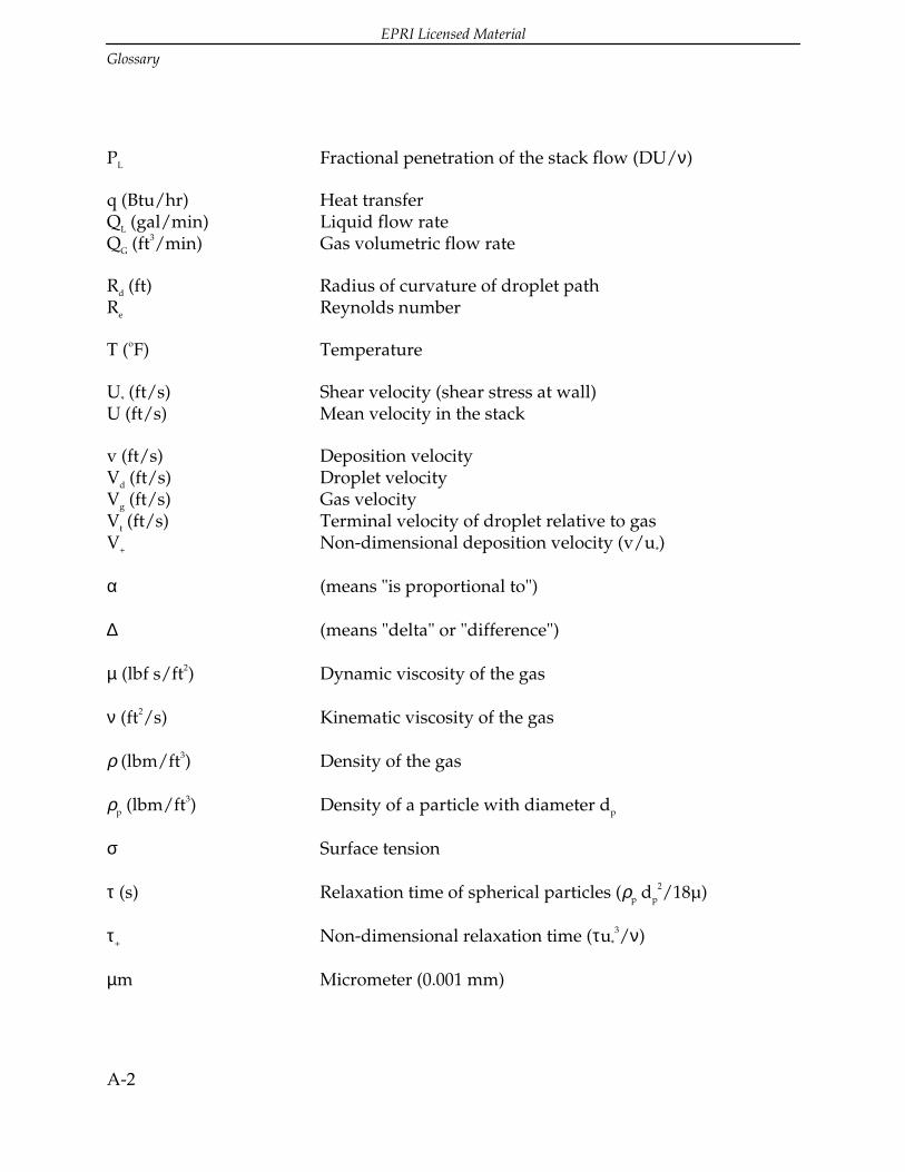
EPRI Licensed Material
Glossary
A-2
PL Fractional penetration of the stack flow (DU/ν)
q (Btu/hr) Heat transferQL (gal/min) Liquid flow rateQG (ft3/min) Gas volumetric flow rate
Rd (ft) Radius of curvature of droplet pathRe Reynolds number
T (oF) Temperature
U* (ft/s) Shear velocity (shear stress at wall)U (ft/s) Mean velocity in the stack
v (ft/s) Deposition velocityVd (ft/s) Droplet velocityVg (ft/s) Gas velocityVt (ft/s) Terminal velocity of droplet relative to gasV+ Non-dimensional deposition velocity (v/u*)
α (means "is proportional to")
∆ (means "delta" or "difference")
µ (lbf s/ft2) Dynamic viscosity of the gas
ν (ft2/s) Kinematic viscosity of the gas
ρ (lbm/ft3) Density of the gas
ρp (lbm/ft3) Density of a particle with diameter dp
σ Surface tension
τ (s) Relaxation time of spherical particles (ρp dp
2/18µ)
τ+ Non-dimensional relaxation time (τu*
3/ν)
µm Micrometer (0.001 mm)

EPRI Licensed Material
Glossary
A-3
A.2 Definitions
absolute humidity - the weight (or mass) of water vapor in a gas water-vapor mixtureper unit volume of space occupied.
absorber - general term for those gas/liquid contacting devices designed primarily forthe removal of SOx pollutants. i.e. scrubber.
absorption - the process by which gas molecules are transferred to a liquid phaseduring scrubbing.
air cubic feet per minute (acfm) - a gas flow rate expressed with respect to operatingconditions (temperature and pressure).
ambient - pertaining to the conditions (pressure, air quality, temperature, etc.) of thesurrounding environment of a plant or scrubbing system.
annual outage - a scheduled period of time (generally four to six weeks) set aside bythe utility once per year to shut down the boiler and/or FGD system for inspection andmaintenance.
annulus - the space between a chimney liner and a chimney shell.
base load - a generating station which is normally operated to take all or part of thenormal load of a system and which, consequently, operates at a constant output.
breeching - the section of ductwork in an FGD system between the absorber outlet ductand the stack.
British thermal unit (Btu) - the amount of heat required to raise the temperature of onepound of water one degree Fahrenheit, averaged from 32 degrees to 212 degrees F.
bypass gas - flue gas which bypasses a scrubber for the purpose of raising wet flue gastemperatures above the saturation temperature.
bypass reheat - a system that increases the temperature of the saturated flue gasleaving an FGD system above dew point by ducting a slip stream of particle-cleanedflue gas from the ESP exit duct past the FGD system to the absorber outlet duct ordirectly to the stack.
capacity factor - the ratio of the average load on a boiler for the period of timeconsidered to the capacity rating of the boiler (actual kWh produced/theoretical kWhproduced x 100).

EPRI Licensed Material
Glossary
A-4
carryover - entrained solids, slurry droplets, and/or liquid droplets that leaves with theflue gas stream exiting a particular stage of a scrubber or absorber.
chimney - a vertical structure at a power plant which encloses one or more flues thatexhaust combustion gases. A chimney is typically constructed out of reinforcedconcrete.
chloride - a compound of chlorine with another element or radical.
choke - the constricted upper section of a steel stack or chimney liner.
cladding - a thin sheet of corrosion resistant alloy (usually nickel alloy or titanium) thatis either resistance welded or roll bonded to carbon steel plate.
closed water loop - the water loop of an FGD system is closed when the fresh makeupwater added exactly equals the evaporative water loss leaving via the stack and thewater chemically or physically bonded to the sludge product.
column - a reinforced concrete chimney shell. Usually encloses one or more chimneyliners. The purpose of the column is to protect the liner from weather and to act as awind shield.
Computational Fluid Dynamics (CFD) - the use of finite element analysis methods tosimulate heat transfer, temperature profiles and fluid and particle movement in boilersand air pollution control equipment.
corrosion - the deterioration of a metallic material by electrochemical attack.
damper - a plate or set of plates or louvers in a duct used to stop or regulate gas flow.
dewpoint - the temperature at which vapor contained in saturated flue gas begins tocondense.
direct combustion reheat - a flue gas reheat system that boosts the temperature of thesaturated gas from the absorber above dewpoint; this is accomplished by injection ofthe hot combustion products generated by oil or gas reheater burners into the gasstream.
efficiency - Ratio of the amount of a pollutant removed to the total amount introducedto the normal operation.
entrainment - the suspension of solids, liquid droplets, or mist in a gas stream.

EPRI Licensed Material
Glossary
A-5
erosion - the action or process of wearing away of a material by physical means(friction).
electrostatic precipitator (ESP) - an air pollution device used to remove particles froman exhaust stream by initially charging them with electrodes and then collecting themon oppositely charged plates.
expansion joint - a small section of ductwork or piping that is designed to passivelyexpand or contract as required by the flexing of more rigid duct runs, piping, or piecesof equipment as such components are exposed to varying external and internaltemperatures.
flue gas desulfurization (FGD) system - an SO2 removal system that uses a wet or dryprocess downstream of a boiler to reduce sulfur dioxide emissions.
fly ash - fine solid particles of noncombustible ash carried out of the boiler by theexiting flue gas.
forced outage - the FGD system is taken out or forced out of service to make necessaryrepairs or modifications regardless of boiler availability such that the system isunavailable for service.
heat exchanger - device used to transfer sensible and/or latent heat from one stream ofmaterial to another to raise or lower the temperature of one of the materials.
induced draft (ID) - a fan used to move an enclosed stream of gases by creating anegative relative pressure in the stream to effectively draw the gas through the system.
indirect hot air - a flue gas reheat system in which reheat is achieved by heatingambient air with an external heat exchanger using steam at temperatures of 350 to 450degrees.
in-line reheater - a heat exchanger installed in the wet flue gas duct downstream of themist eliminator, usually consisting of hot water or steam coils used to boost the wet fluegas temperature above dewpoint.
liner - the flue located inside of a chimney or stack that exhausts combustion gases.
lining - a metal, organic, or inorganic type material applied to a shell of an FGD systemcomponent which is intended to protect the shell from abrasion, heat, and/or corrosion.
liquid collection devices - devices such as gutters, troughs and drains used in absorberoutlet ductwork or stack liners within an FGD system to collect liquid carried over froma wet scrubber.

EPRI Licensed Material
Glossary
A-6
load factor - the ratio of the average load in kilowatts supplied during a designatedperiod to the peak or maximum load in kilowatts occurring in that period.
mist - dispersion of liquid particles in a gas stream, carryover from a gas-liquid contactoperation.
mist eliminator - a piece or section of pollution hardware used to remove a dispersionof liquid particles from a gas stream.
megawatt (MW) - unit used to describe gross or net power generation of a particularfacility. One watt equals one joule per second. One megawatt equals 106 watts.
micrometer - unit of measure equivalent to 0.0000394 inch or 0.001 mm.
new (as opposed to retrofit for FGD systems) - FGD unit and boiler were designed atthe same time, or space for addition of an FGD unit was reserved when the boiler wasconstructed.
NOx - a symbol meaning oxides of nitrogen (e.g., NO and NO2).
NSPS (New Source Performance Standards) - environmental regulations that apply toa new installation, referring primarily to the Federal NSPS that applies to installationsbeginning construction on or after August 17, 1971.
opacity - the degree to which emissions reduce the transmission of light and obscurethe view of an object in the background.
open water loop - the water loop of an FGD system is open when the fresh makeupwater added exceeds the evaporative water loss leaving via the stack and the waterchemically or physically bonded to the sludge product.
outage - that period of time when the boiler and/or FGD system is shut down forinspection and maintenance. Outages may be either forced or scheduled.
particulate matter - finely divided solid particles entrained in the gas stream (fly ash,coal fines, dried reaction byproducts, etc.).
peak load - a boiler that is normally operated to provide power during maximum loadperiods.
pH - the hydrogen ion concentration of a water or slurry to denote acidity or alkalinity.
plume (stack plume) - the visible emission from a flue (stack).

EPRI Licensed Material
Glossary
A-7
plume downwash - the phenomenon which occurs when the flue gas exits a stack andthe vapor plume drops below the top of the stack before evaporating or dispersing intothe atmosphere. Usually occurs on stacks which operate at a relatively low exit velocity.
ppm (parts per million) - units of concentration that in wastewater applications isequal to milligrams per liter and in air pollution applications is equal to moles ofpollutant to million moles diluent.
pressure drop - the difference in force per unit area between two points in a fluidstream, due to resistive losses in the stream.
rain hood - the component at the top of a stack which covers the annular space.
reheat - the process of increasing the flue gas temperature down stream of a wetscrubber. Reheat can be supplied by in-line, indirect hot air, direct combustion or bypartial bypass of unscrubbed flue gas.
reheater - device used to raise the temperature of the scrubbed gas stream to preventcondensation and corrosion of downstream equipment, avoid visible plume, and/orenhance plume rise and dispersion.
relative humidity (also relative saturation) - the ratio of the weight (or mass) of watervapor present in a unit volume of gas to the maximum possible weight (or mass) ofwater vapor in unit volume of the same gas at the same temperature and pressure. Theterm "saturation" refers to any gas-vapor combination, while "humidity" refersspecifically to an air-water system.
removal efficiency:
particulate matter - the actual percentage of particulate matter removed by theemission control system (mechanical collectors, ESP, or fabric filter and FGD)from the untreated flue gas.
SO2 - the actual percentage of SO2 removed from the flue gas by the FGD system.
total unit design - the designed percentage of mass of SO2 or particulate matterentering the stack to the mass of the material in the flue gas exiting the boilerregardless of the removal efficiency of an individual component or thepercentage of the exiting flue gas actually being scrubbed.
retrofit - the FGD unit will be/was added to an existing boiler not specifically designedto accommodate an FGD system.

EPRI Licensed Material
Glossary
A-8
saturated - the situation when a gas or liquid is filled to capacity with a certainsubstance. No additional amount of the same substance can be added under the givenconditions.
saturation temperature - the temperature to which flue gas drops when it is saturatedby scrubbing in a wet FGD system.
scale - deposits of slurry solids (calcium sulfite or calcium sulfate) that adhere to thesurfaces of FGD equipment, particularly absorber/scrubber internals and misteliminator surfaces.
scheduled outage - a planned period of time set aside periodically for inspection andmaintenance of the boiler and/or FGD system.
scrubber - a device that promotes the removal of pollutant particles and/or gases fromexhaust streams of combustion or industrial processes by the injection of an aqueoussolution or slurry into the gas stream. i.e. absorber.
sludge - the material containing high concentrations of precipitated reactionbyproducts and solid matter collected and/or formed by the FGD process (composedprimarily of calcium-based reaction byproducts, excess scrubbing reagent, fly ash, andscrubber liquor).
slurry - a watery mixture of insoluble matter (usually lime or limestone).
SOx - a symbol meaning oxides of sulfur (e.g., SO2 and SO3).
stack - a vertical structure at a power plant which encloses one or more flues thatexhaust combustion gases.
stack flue - the inner duct or liner in a stack through which the flue gas is conveyed.
stack exit velocity - the exiting velocity of the flue gas out the top of the stack.
stack liner velocity - area average gas velocity inside the liner.
stack liquid discharge - liquid that is discharged from a stack and falls to the groundprior to evaporating.
standard conditions - a set of physical constants for the comparison of different gasvolume flow rates (68 degrees F, 29.92 inches Hg, barometric pressure.
standard cubic feet per minute (scfm) - units of gas flow rate at standard conditions.

EPRI Licensed Material
Glossary
A-9
steel stack - a vertical structure at a power plant that exhausts combustion gases. Theprimary supporting shell is made of steel.
superficial gas velocity - the area average flue gas velocity through a mist eliminator orother component of an FGD system.
temperature, dry bulb - the temperature of a gas or mixture of gases indicated by athermometer after correction for radiation.
temperature, wet bulb - a measure of the moisture content of air (gas) indicated by awet bulb psychrometer.
total controlled capacity (TCC) - the gross rating (MW) of a unit brought intocompliance with FGD, regardless of the percent of flue gas treated at the facility.
turning vanes (i.e. vanes) - devices used in ductwork or chimney liners to control gasflow direction. Usually fabricated from flat or curved plates.
unit rating:
gross - maximum continuous generating capacity in MW
net - gross unit rating less the energy required to operate ancillary stationquipment, inclusive of emission control systems.
wallpaper - thin sheets of corrosion resistant alloy material welded to new or existingcarbon steel plate.
water loop - all aqueous mass flows from inlet (e.g., seal water, quench water, scrubberliquor) to outlet of an FGD system (e.g., evaporation via stack, pond evaporation, wastedisposal).
wet stack - a chimney, stack, or flue that exhausts saturated, completely scrubbed fluegas. Wet stacks are located downstream from a wet FGD system. Wet stack operationdoes not utilize any flue gas reheat system or partial bypass. Wet stacks are equippedwith corrosion resistant liners for handling the wet, acidic flue gas exiting the FGDsystem.
zero discharge - a pollution regulation requiring that no effluent waste stream bedischarged back into the environment, with the exception of evaporation via ponds andstacks (e.g., pond runoff or direct piping of spent slurry or waste into nearbywaterways or tributaries would be prohibited).

EPRI Licensed Material
Glossary
A-10
A.3 Abbreviations
absolute abs inside diameter id
actual cubic feet per minute acfm interior int
alloy aly kilowatt kW
ambient am lining lng
average avg low-alloy steel las
bottom bot maintenance maint
brick brk manager mgr
British thermal unit Btu material matl
bypass byp maximum max
carbon steel cs megawatt mW
center line cl mile mi
clean out co minimum min
clear cl minute min
column col module mdl
concrete conc negative neg or (-)
condensate cnds nickel steel ns
continue, continuous cont nitrogen oxide NOx
contractor contr no data available nda
corrosion crsn not applicable na
corrosion-resistant cre not available na
cubic foot cu ft outside diameter od
damper dmpr particulate matter
degrees Celsius oC < 10 microns in size pm10
degrees Fahrenheit oF parts per million ppm
demolition dml percent pct or (%)
dew point dp plate pl

EPRI Licensed Material
Glossary
A-11
diameter dia plus or minus porm or (±)
draft dft positive pos
efficiency eff pound lb
elevation el pound force per square foot psf
engineer engr pound force per square inch psi
equation eq pound per cubic foot pcf
example ex pressure press
expansion jt exp jt reheater rhr
exterior ext reinforced concrete rc
firebrick fbck required reqd
floor drain fd research and development R&D
foot ft scale model scmod
foot per second fps square foot sq ft
forced-draft fd stainless steel sst
foundation fdn standard std
galvanize galv static pressure st pr
gallon per minute gpm steel stl
galvanize galv sulfur dioxide SO2
glass block glb sulfur trioxide SO3
gutter gut sulfuric acid H2SO4
horizontal horiz temperature temp
hour hr temperature differential td
inch in velocity vel
inches of water column in H2O viscosity visc
induced-draft id water H2O
inlet inl

EPRI Licensed Material
Glossary
A-12
A.4 Units and Conversion Factors
To Obtain Multiply By
Atmospheres Feet of water @ 4°C 2.950 x 10-¨
Atmospheres Inches of mercury @ 0°C 3.342 x 10-¨
Atmospheres Pounds per square inch 6.804 x 10-¨
Inches of mercury @ 0°C
Pounds per square inch 2.036
Kilowatts Btu per minute 1.758 x 10-¨
Temperature Conversions:
oF=1.8 x toC + 32
oC=(toF - 32)/1.8
Liquid Load Conversion:
Liquid Load (grains / acf) =Q (gal / min 57,700)
Q (acfm)
L
G
×

EPRI Licensed Material
B-1
B LIST OF KNOWN WET STACKS
The list of known wet stacks has been generated from several sources. The first sourceis from a published industry list of Phase I Scrubber construction projects. The secondsource is from the 1991 Energy Information Administration (EIA) Form 767 ScrubberData. The third and final source is based on professional experience in the Flue GasDesulfurization (FGD) industry. The format of this list is based upon the premise thateach individual liner represents a separate wet stack. The list includes units presentlyon line and units which were under construction at the time this guide was written.

EPRI Licensed Material
List Of Known Wet Stacks
B-2
Table B-1List of Known Wet Stacks

EPRI Licensed Material
List Of Known Wet Stacks
B-3


EPRI Licensed Material
C-1
C RESULTS OF SURVEY
C.1 Wet Stack Survey Data
The data collection phase of the study involved identifying utilities operating orconstructing wet stacks in the United States. These utilities were then contacted andasked to complete a short questionnaire covering various aspects of the wet stacksystem geometry and operating conditions. The survey data represents informationcollected from approximately 31 utilities which operate 68 wet stack liners. Data fromseveral units under construction have also been included. The data includes all of theimportant design and operating parameters of the wet stacks.
The first step in the data collection phase of the wet stack study consisted of preparinga short questionnaire. The questionnaire focused on topics such as the wet stack systemgeometry and operating conditions of the unit. Questions about problems encounteredduring unit operation, such as plume down wash and stack liquid discharge, were alsoincluded in the survey. (Refer to Section 1 of the Wet Stacks Design Guide for adescription of plume down wash and stack liquid discharge.)
The criteria used to identify a wet stack include: 1) a full load stack temperature of 135degrees F (57°C) or less (which assumes that no bypass gas or reheat is used to raiseflue gas absorber exit temperatures) and 2) a unit which operates with a wet scrubber.
The list of wet stacks identified by this criteria and the respective plant personnelcontacts were generated from the 1991 Energy Information Administration Form 767Scrubber Data. This data was sorted in ascending order of full load stack temperatures.All utilities with units reporting a full load stack temperature of 135 degrees F (57°C) orless were contacted. Additional questionnaires were also sent to utilities appearing on apublished industry list of Phase I scrubber construction projects.
Once the list of identified wet stack units was compiled, each contact was sent a blankquestionnaire with a letter explaining the purpose of the survey. The utilities gathereddata during the next several weeks. Once a utility had filled out the questionnaire ascompletely as possible, the completed questionnaire was either sent back via fax or theinformation was relayed via the telephone. In general, most of the data requested wasfurnished by the utilities. However, some utilities had difficulty obtaining variouspieces of information and in those cases the data was omitted. Additional information

EPRI Licensed Material
Results Of Survey
C-2
was filled in such as stack inlet and exit velocities using the information provided bythe utilities.
The data provided on the completed questionnaires was then converted to a spreadsheet format for record keeping purposes and ease of manipulation. Responses forcertain categories could then be easily compared for several different utilitiessimultaneously.
Nearly half of the utilities that participated in the study reported some instance of down washor stack liquid discharge. The severity of the problems encountered varied from veryinfrequent light misting to heavy rain. The location of stack liquid discharge fallout reportedranged from the area immediately surrounding the stack up to one-half mile from the stack.Only one utility reported stack liquid discharge fallout beyond the plant site.
Several direct relationships are apparent from the wet stacks data. Stack liquiddischarge appears to be directly related to a lack of liquid collection devices such asgutters in the liners and absorber outlet ductwork. In addition, stack droplet dischargeseems to be more prevalent on units with an exit velocity greater than 75 ft/s (23 m/s).However, this relationship does not hold true in every case.
Based on reported data, a direct relationship between an FGD system which utilizes aparticular type of mist eliminator and occurrences of stack liquid discharge is not apparent.However, the City of Springfield, Missouri eliminated stack liquid discharge problems at theirSouthwest Unit 1 station by inclining the existing mist eliminators 20 degrees.
Downwash problems were reported much less frequently than stack liquid dischargeproblems in the survey. The only serious case of plume downwash was reported bySeminole Electric Cooperative's Seminole Station Units 1 and 2. The exit velocityreported for these units is relatively low at 33 ft/s (10 m/s). Downwash was reportedby several units to be more prevalent on cold days. In addition, the reported cases ofdownwash in this survey occurred only on units with brick liners without chokes.
Acid resistant brick liners are the most prevalent wet stack liners in service in theUnited States. This is due mostly to economic considerations. Of the 36 acid resistantbrick liners operating as wet stacks, 34 (or 94 percent) operate with annuluspressurization fans. Significant acid leaching through the brick liner has occurred onunits operating without annulus pressurization fans. For example, Mitchell Unit 3,which is operated by Allegheny Power Service Corporation has experienced significantacid leaching through the brick liner without annulus pressurization.
Wet stack liners constructed with acid resistant brick are typically operated between -3.0 to+3.0 inches of water column (-0.75 to 0.75 kPa) static pressure in the liner at the breechinglevel.

EPRI Licensed Material
Results Of Survey
C-3
Table C-1Wet Stack Survey Data

EPRI Licensed Material
Results Of Survey
C-4
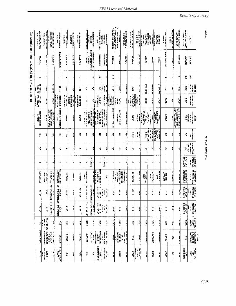
EPRI Licensed Material
Results Of Survey
C-5

EPRI Licensed Material
Results Of Survey
C-6

EPRI Licensed Material
Results Of Survey
C-7

EPRI Licensed Material
Results Of Survey
C-8

EPRI Licensed Material
Results Of Survey
C-9
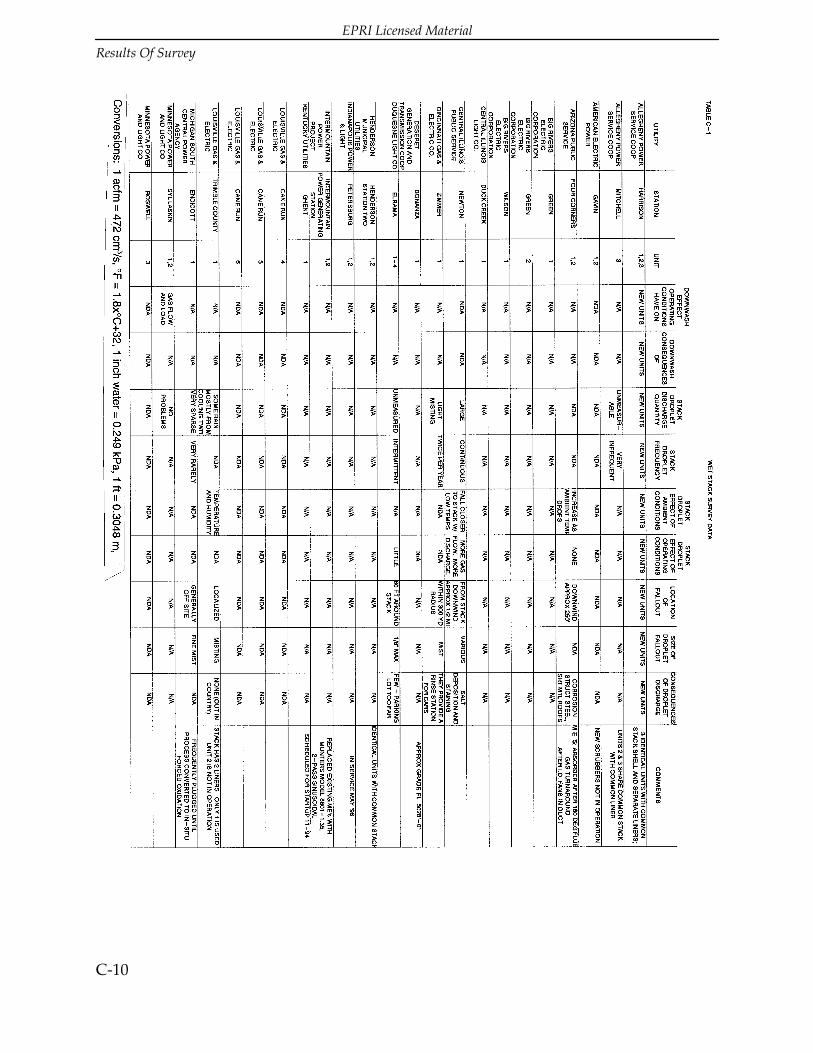
EPRI Licensed Material
Results Of Survey
C-10

EPRI Licensed Material
Results Of Survey
C-11

EPRI Licensed Material
Results Of Survey
C-12
C.2 Average Stack Velocities for Various Types of Lining Materials
The stack exit velocity averages for various types of wet stack liners are shown in TableC-2. The exit velocities averages range from 43 ft/s (13 m/s) for Pennguard borosilicateglass block and polyester flake glass lined, carbon steel liners to 79 ft/s (24 m/s) forfibrecrete 214/222 lined, carbon steel liners. The stack exit velocities and therecommended stack liner velocities in Table 2-3 can be compared for constant diameterliners without a choke.
The wet stack industry survey indicates a total of 72 individual wet stack linerscurrently exist in the United States. Of these, data was collected on 68 of the liners. Ofthe 68 liners, 36 of them are constructed from acid resistant brick. The survey indicatesthat 12 liners are constructed out of Alloy 625 or Alloy C-276. The other four alloy linersuse titanium. Only 11 of the 68 liners in the database use FRP or coated carbon steelliners.
The majority of the Phase I scrubber projects are currently under construction and donot yet have operating data available. Therefore, insufficient data exists which wouldallow any conclusions to be drawn concerning recommended stack exit velocities.

EPRI Licensed Material
Results Of Survey
C-13
Table C-2

EPRI Licensed Material
Results Of Survey
C-14
C.3 Exit Velocities for Existing Acid Resistant Brick Liners
The stack exit velocity data for existing acid resistant brick liners as reported by thedifferent utilities is shown graphically in Table C-3. Table C-3 also shows the range ofmaximum liner velocities recommended for new wet brick liners in Section 2 of thisdesign guide. The majority of the existing stack exit velocities do not fall within therecommended liner velocity range. This could be due to the following factors:
• The brick liners may not have been originally designed for wet operation.
• For tapered liners and liners with a choke, the stack exit velocity may besignificantly higher than the average liner velocity.

EPRI Licensed Material
Results Of Survey
C-15
Table C-3


EPRI Licensed Material
D-1
D STACK LIQUID DISCHARGE MEASURING
TECHNIQUES
Measurement methods for determining stack liquid discharge include a video dropletanalyzer (VDA), laser optical particle counter, hot-wire anemometer, treated paper, dyetracers, chemical element balance and the phase Doppler particle analyzer (PDPA).These methods were originally developed for carryover measurement in misteliminators, where gas flow velocities are about 25 percent in order of magnitudecompared to flow velocities in wet stacks which range from 40 to 80 ft/s (12-24 m/s).
The video droplet analyzer employs a video camera and a synchronized high-speedstrobe illuminator hooked up to a probe. Droplets are "frozen" as they pass through thesensing zone at a rate of 30 frames per second. Droplet size and quantity for each rangeof droplet diameter are measured. Gas velocities are measured by an independentprocedure, for eg. a conventional s-
type pitot. Droplet data and gas velocity for each measurement point are then used tocalculate the amount of stack liquid discharge. The VDA offers the advantages of in-situ sampling and a relatively wide spectrum of droplet sizes (30 to 5300 microns)monitored. One disadvantage of the VDA method is the required independentmeasurement of gas velocity, which has to be accurately gauged at each measurementpoint. Other disadvantages include the bulkiness of the accessory equipment and thetechnical expertise required to operate the equipment and to interpret the collecteddata.
A probe-mounted model of the laser optical particle counter is the PCSV-Pmanufactured by Insitec. The PCSV-P uses a low intensity He-Ne laser beam that splitsinto two separate beams prior to transmission across the probe viewing zone. Dropletdiameters are measured directly through the analysis of light rays refracted by singledroplets passing through the laser beams. The PCSV-P offers the advantage of bothliquid discharge and gas velocity measurements in one probe. A major drawback ofthis method is that measurements for droplets bigger than 100 microns in diameter arenot accurate. Also disadvantageous is the bulky associated equipment and the technicalexpertise needed to install and operate the apparatus, as well as, to evaluate the data.
The Army Insecticide Measurement System (AIMS) made by KLD Associates, is a hot-wire anemometer that employs a heated platinum sensor wire in a bridge circuit to

EPRI Licensed Material
Stack Liquid Discharge Measuring Techniques
D-2
generate a voltage pulse when a droplet cools the wire after impingement. Gas velocityis also determined, although in relatively humid gas streams, the readings areinaccurate. Portability of equipment and ease of installation and operation of the AIMSunit are advantages of this method. However, the largest droplet size that can bemeasured is only about 800 microns and the sensor wire is fragile and prone tobreakage.
The treated paper method uses a piece of paper exposed to the gas stream to producestains when droplets impact the paper. One way of preparing the treated paper is bysoaking filter paper in a 1% solution of potassium ferrocyanide. An apparatus to holdand expose the treated paper has to be custom made since such equipment is not atpresent commercially available. The advantages of this method are the relatively simpleequipment set-up and the immediate qualitative indication of droplet size andquantity. Disadvantages of the treated paper method include the time consumingprocess of treating the paper and the tedious placement and removal of the paper in thegas stream. Other disadvantages are the required independent measurement of gasvelocity and the cumbersome apparatus.
In the dye tracer method, a foreign substance not typically found in the source liquorsis added to the system. When the stack liquid discharge is sampled, the tracerconcentrations are then used to determine the contributions of each source. It isimperative to use tracers that are stable under the operating conditions, not affected bythe collection process and easily analyzed in the samples. Tracers like the fluorescentdyes fluorescein and rhodamine could be used. The dye tracer method offers theadvantage of a relatively easy sampling method. Disadvantages include the careprerequisite in applying the dyes and analyzing liquid discharge samples. Anotherdisadvantage of this method is the potential degradation of the dyes and/or thecomplication of analysis by other chemicals that may be present in the system.
The chemical element balance method assesses the differences in the chemicalcomposition of the streams contributing to stack liquid discharge. This method assumesthat the slurry from the absorber has a composition and solids content equivalent tothat of the stack liquid discharge. This method measures a solids carryover. The liquiddischarge is then calculated on the basis of the contributing stream compositions. Theadvantages of the chemical balance method are the easy sampling procedure and theuse of the inherent differences in the contributing streams without adding chemicals tothe system. The major disadvantages of this method are the extensive chemical analysisof the samples and the likelihood of difficulty in differentiating between sources thathave similar compositions.
The phase Doppler particle analyzer made by Koch Engineering Company Inc., usestwo intersecting laser beams to provide a sensing zone. As droplets pass through theprobe volume, they scatter light which is analyzed to determine droplet size, count andvelocity. An advantage of the PDPA is the broad range of droplet sizes (0.5 to 1500
EPRI Licensed Material
Stack Liquid Discharge Measuring Techniques
D-3
microns) which can be measured. The analysis of the data collected using the PDPAprovides droplet size, velocity distributions, various mean diameters, and the volumeflux (cc/cm2-s or gpm/ft2). Koch claims that comparative tests with other measurementmethods have been evaluated and show good correlation. In any case, the PDPApresents itself as a possible alternative method in addition to the other fore-mentionedmethods for measuring stack liquid discharge.


EPRI Licensed Material
E-1
E PROCESS FLOW CHART OUTLINES
Included in this section are the process flow chart outlines for a new or retrofit wetstack and for a wet stack conversion. These outlines provide a detailed listing of flowchart activities that are presented in Figures E-1 and E-2. Additional descriptions ofthese activities are found in Sections 2 and 3.
E.1 Process Flow Chart Outline For New/Retrofit Wet Stack
Note: A diagram of this process flow chart is provided in Figure E-1.
1.0 Feasibility Study (Phase I)1.1. Address Regulatory Issues1.1.1 Dispersion Modeling1.1.2 Permit Requirements1.1.3 Tradeoffs Between SO2 Removal Efficiency, Liner Material/Exit
Velocity, and Ground Level Concentrations1.1.4 Scrubber Performance Enhancement to Increase Removal Efficiency
and Decrease Ground Level Concentrations1.1.5 Wet Lands1.1.6 Flood Plains
1.2 Define Existing Plant Considerations1.2.1 Number of Units1.2.2 Number of Liners1.2.3 Bypass Options1.2.4 Reliability Requirements1.2.5 Operating Philosophy1.2.6 Outage Time Available1.2.7 Plant Layout/Location1.2.8 Proximity to Existing Chimneys or Structures (Vortex Shedding
between 2 Structures)1.2.9 Future Use/Operating Conditions/Design Life Span1.2.10 Soil Conditions1.2.11 Preliminary Economic Analysis Guidelines
1.2.11.1 What to Consider1.2.11.2 Ways to Estimate Non-Standard Items Such as Model
Study, Liquid Collection System, Etc.

EPRI Licensed Material
Process Flow Chart Outlines
E-2
1.3 Define Operating Parameters1.3.1 Gas Flows1.3.2 Gas Temperatures
1.3.2.1 Scrubbed Gas Operating Range1.3.2.2 Bypass Gas Operating Range1.3.2.3 Upset Conditions (Air Heater Failure)
1.3.3 Pressure1.3.4 FGD System Type1.3.5 Coal Analyses or Coal Composition1.3.6 Flue Gas Composition1.3.7 Efficiency of Mist Eliminators1.3.8 Scrubbed Only or Combined Scrubbed/Bypass
1.4 Determine Stack Height1.4.1 Good Engineering Practice (GEP) Requirements1.4.2 Draft Considerations1.4.3 Adjacent Building Sizes1.4.4 Local Conditions, Terrain
1.5 Establish Liner Material Options1.5.1 Acid Resistant Brick1.5.2 Coated Carbon Steel1.5.3 Borosilicate Glass Block on Carbon Steel1.5.4 Fiberglass Reinforced Plastic1.5.5 Nickel Alloy1.5.6 Titanium1.5.7 Combination/Multiple Materials
1.6 Perform Operating Conditions vs. Liner Design Compatibility Analysis1.6.1 FGD System Type vs. Liner Material Options1.6.2 Operating Conditions vs. Liner Material Options1.6.3 Design Constraints (seismic, temperature, etc.) vs. Liner Material
Options
1.7 Select Design Velocity Limit to Prevent Liquid Reentrainment forEach Candidate Liner Material1.7.1 Breech Entry1.7.2 Liner1.7.3 Liner or Choke Exit
1.8 Perform Preliminary Economic Analysis of Liner Material Optionsfor Wet Stack Operation1.8.1 Capital Costs
1.8.1.1 Chimney Column

EPRI Licensed Material
Process Flow Chart Outlines
E-3
1.8.1.2 Liner1.8.1.3 Breeching1.8.1.4 Foundation
1.8.2 Operating Costs1.8.3 Maintenance Costs1.8.4 Present Value Analysis
1.9 Select Liner Material(s) for Wet Stack Operation
1.10 Determine Reheat System Design Requirements (if necessary)1.10.1 Materials of Construction.10.2 Energy Requirements1.10.3 Energy Source1.10.4 Equipment Requirements
1.11 Perform Economic Analysis of Wet Stack vs. Reheat Operation(if necessary)1.11.1 Capital Costs1.11.2 Operating Costs1.11.3 Maintenance Costs1.11.4 Present Value Analysis
1.12 Select Wet Stack or Reheat Operation (if necessary)
2.0 Design Process (Phase II)
2.1 Perform Component-by-Component Design2.1.1 Establish Design Criteria
2.1.1.1 Subsurface Investigation2.1.1.2 Foundation Type
2.1.1.2.1 Soil Bearing2.1.1.2.2 Piling2.1.1.2.3 Drilled Shafts
2.1.1.3 Chimney Foundation Design Requirements2.1.1.4 Reinforced Concrete Chimney or Steel Stack Design
Requirements2.1.1.5 Liner Design Requirements2.1.1.6 Ductwork Design Requirements2.1.1.7 Miscellaneous Design Requirements
2.1.2 Define Absorber Outlet Duct and/or Bypass Duct Geometry2.1.2.1 Evaluate Mixing Zones

EPRI Licensed Material
Process Flow Chart Outlines
E-4
2.1.2.2 Damper Locations2.1.2.3 Expansion Joint Locations
2.1.3 Define Chimney Geometry2.1.3.1 Liner Height2.1.3.2 Liner Diameter(s)2.1.3.3 Liner Base Elevation (At Grade or Above Grade)2.1.3.4 Annulus Space2.1.3.5 Plumb or Tapered Liner2.1.3.6 Plumb or Tapered Column2.1.3.7 Choke2.1.3.8 Liner Projection above Column2.1.3.9 Liner Floor Configuration2.1.3.10 Breech Opening Orientation, Size, Elevation2.1.3.11 Access Requirements
2.1.3.11.1 Interior vs. Exterior Platforms, Ladders,and Elevator
2.1.3.11.2 Continuous Emissions Monitor (CEM) Access2.1.3.11.3 Testing Access2.1.3.11.4 Inspection Access2.1.3.11.5 Maintenance Access
2.2 Adjust Design for Suitability and Compatibility for Liquid Collection
2.3 Perform Flow Model Study2.3.1 Physical Flow Model2.3.2 Condensation Calculations2.3.3 Determine Liquid Collection Devices
2.3.3.1 Gutters and Flow Guides2.3.3.2 Vanes and Baffles2.3.3.3 Drains and Troughs2.3.3.4 Liner Floor Drainage2.3.3.5 Drain Pipes and Gas Seals
2.4 Prepare Bid Specifications, for Chimney Contract2.4.1 General Requirements (Including Safety Issues for Confined Space)2.4.2 Site Work2.4.3 Concrete2.4.4 Masonry2.4.5 Metals: Structural and Miscellaneous2.4.6 Thermal and Moisture Protection2.4.7 Doors2.4.8 Finishes2.4.9 Conveying Systems

EPRI Licensed Material
Process Flow Chart Outlines
E-5
2.4.10 Mechanical2.4.11 Electrical
2.5 Perform Detailed Design of Chimney for Construction
E.2 Process Flow Chart Outline For Conversion to Wet Stack Operation
Note: A diagram of this flow chart is provided in Figure E-2.
1.0 Feasibility Study (Phase I)
1.1 Address Regulatory Issues1.1.1 Dispersion Modeling1.1.2 Permit Requirements1.1.3 Tradeoffs Between SO2 Removal Efficiency, Liner Material/Exit
Velocity, and Ground Level Concentrations1.1.4 Scrubber Performance Enhancement to Improve Removal
Efficiency and Decrease Ground Level Concentrations
1.2 Define Existing Plant Considerations1.2.1 Number of Units1.2.2 Number of Liners1.2.3 Bypass Options1.2.4 Reliability Requirements1.2.5 Operating Philosophy1.2.6 Outage Time Available1.2.7 Plant Layout/Location1.2.8 Location of FGD Systems1.2.9 Location of Fans1.2.10 Capacity of Fans1.2.11 Future Use/Operating Conditions/Design Life Span1.2.12 CEM Systems1.2.13 Soil Conditions1.2.14 Preliminary Economic Analysis Guidelines
1.2.14.1 What to Consider1.2.14.2 Ways to Estimate Non-Standard Items Such as Model
Study, Liquid Collection System, Etc.
1.3 Define Operating Parameters1.3.1 Gas Flows1.3.2 Gas Temperatures
1.3.2.1 Scrubbed Gas Operating Range1.3.2.2 Bypass Gas Operating Range

EPRI Licensed Material
Process Flow Chart Outlines
E-6
1.3.2.3 Upset Conditions (Air Heater Failure)1.3.3 Pressure1.3.4 FGD System Type1.3.5 Coal Analyses or Coal Composition1.3.6 Flue Gas Composition1.3.7 Efficiency of Mist Eliminators
1.3.7.1 Determine Existing System Liquid Carryover1.3.7.2 Measure Droplet Size and Quantity
1.3.8 Scrubbed Only or Combined Scrubbed/Bypass
1.4 Review Existing Design Parameters1.4.1 Foundation1.4.2 Reinforced Concrete Chimney or Steel Stack1.4.3 Liner1.4.4 Ductwork
1.5 Evaluate Existing Stack Height1.5.1 Good Engineering Practice Requirements (GEP)1.5.2 Draft Considerations1.5.3 Adjacent Building Sizes1.5.4 Local Conditions, Terrain
1.6 Evaluate Existing Stack, Liner, and Outlet Duct1.6.1 Material(s)1.6.2 Condition (Inspection Reports)1.6.3 Structural Integrity for Current Code Requirements1.6.4 Flue Gas Velocity1.6.5 Ability to Incorporate Liquid Collection Devices1.6.6 Acceptability of Existing Stack Height per Step 1.5 above.1.6.7 Ability to Convert Annulus to Pressurized System1.6.8 Effect of Conversion on Existing CEM Instruments and Locations
1.7 Determine Insulation Requirements1.7.1 Liner1.7.2 Ductwork
1.8 Determine Liner Alternatives1.8.1 Existing Liner Acceptable1.8.2 Modify or Reline Existing Liner1.8.3 Replace Existing Liner1.8.4 Construct New Chimney
1.9 Establish Liner Material Options1.9.1 Acid Resistant Brick
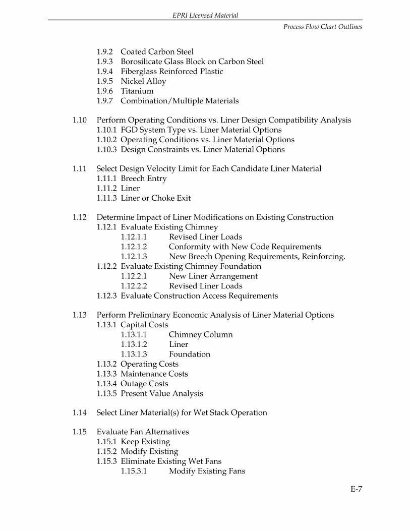
EPRI Licensed Material
Process Flow Chart Outlines
E-7
1.9.2 Coated Carbon Steel1.9.3 Borosilicate Glass Block on Carbon Steel1.9.4 Fiberglass Reinforced Plastic1.9.5 Nickel Alloy1.9.6 Titanium1.9.7 Combination/Multiple Materials
1.10 Perform Operating Conditions vs. Liner Design Compatibility Analysis1.10.1 FGD System Type vs. Liner Material Options1.10.2 Operating Conditions vs. Liner Material Options1.10.3 Design Constraints vs. Liner Material Options
1.11 Select Design Velocity Limit for Each Candidate Liner Material1.11.1 Breech Entry1.11.2 Liner1.11.3 Liner or Choke Exit
1.12 Determine Impact of Liner Modifications on Existing Construction1.12.1 Evaluate Existing Chimney
1.12.1.1 Revised Liner Loads1.12.1.2 Conformity with New Code Requirements1.12.1.3 New Breech Opening Requirements, Reinforcing.
1.12.2 Evaluate Existing Chimney Foundation1.12.2.1 New Liner Arrangement1.12.2.2 Revised Liner Loads
1.12.3 Evaluate Construction Access Requirements
1.13 Perform Preliminary Economic Analysis of Liner Material Options1.13.1 Capital Costs
1.13.1.1 Chimney Column1.13.1.2 Liner1.13.1.3 Foundation
1.13.2 Operating Costs1.13.3 Maintenance Costs1.13.4 Outage Costs1.13.5 Present Value Analysis
1.14 Select Liner Material(s) for Wet Stack Operation
1.15 Evaluate Fan Alternatives1.15.1 Keep Existing1.15.2 Modify Existing1.15.3 Eliminate Existing Wet Fans
1.15.3.1 Modify Existing Fans

EPRI Licensed Material
Process Flow Chart Outlines
E-8
1.15.3.2 Add New Fans Upstream of FGD System1.15.3.3. Consider Fan Wash Systems
1.15.4 Annulus Pressurization System1.15.5 Consider Draft Changes Resulting from Conversion to Wet Stack
Operation
1.16 Collect Baseline Performance Data1.16.1 Stack Droplet Test
1.16.1.1 With Reheat1.16.1.2 Without Reheat
1.16.2 Determine Required Performance of Modified System
1.17 Determine Reheat System Design Requirements1.17.1 Materials of Construction1.17.2 Energy Requirements1.17.3 Energy Source1.17.4 Equipment Requirements
1.18 Perform Economic Analysis of Wet Stack vs. Reheat Operation1.18.1 Capital Costs1.18.2 Operating Costs1.18.3 Maintenance Costs1.18.4 Outage Costs1.18.5 Present Value Analysis
1.19 Select Wet Stack or Reheat Operation
2.0 Design Process (Phase II)
2.1 Perform Component-by-Component Design2.1.1 Establish New Design Parameters
2.1.1.1 Wind2.1.1.2 Seismic2.1.1.3 Codes
2.1.2 Define Chimney Geometry2.1.2.1 Liner Height2.1.2.2 Liner Diameter(s)2.1.2.3 Liner Base Elevation (At Grade or Above Grade)2.1.2.4 Annulus Space2.1.2.5 Plumb or Tapered Liner2.1.2.6 Choke2.1.2.7 Liner Projection above Column2.1.2.8 Liner Floor Configuration

EPRI Licensed Material
Process Flow Chart Outlines
E-9
2.1.2.9 Breech Opening Orientation, Size, Elevation2.1.2.10 Access Requirements
2.1.2.10.1 Interior vs. Exterior Platforms, Ladders, andElevator
2.1.2.10.2 Continuous Emissions Monitor (CEM) Access2.1.2.10.3 Testing Access2.1.2.10.4 Inspection Access2.1.2.10.5 Maintenance Access
2.2 Adjust Design for Suitability and Compatibility for Liquid Collection
2.3 Perform Flow Model Study2.3.1 Physical Flow Model2.3.2 Condensation Calculations2.3.3 Determine Liquid Collection Devices
2.3.3.1 Gutters and Flow Guides2.3.3.2 Vanes and Baffles2.3.3.3 Drains and Troughs2.3.3.3 Liner Floor Drainage2.3.3.5 Drain Pipes and Gas Seals
2.4 Prepare Bid Specifications for Chimney Contract2.4.1 General Requirements (Including Safety Issues for Confined Space2.4.2 Site Work2.4.3 Concrete2.4.4 Masonry2.4.5 Metals: Structural and Miscellaneous2.4.6 Thermal and Moisture Protection2.4.7 Doors2.4.8 Finishes2.4.9 Special Construction2.4.10 Conveying Systems2.4.11 Mechanical2.4.12 Electrical
2.5 Perform Detailed Design of Chimney for Construction

EPRI Licensed Material
Process Flow Chart Outlines
E-10
Figure E-1 Process Flow Chart for New/Retrofit Wet Stack Design

EPRI Licensed Material
Process Flow Chart Outlines
E-11
Figure E-2 Process Flow Chart for Conversion of Existing Stack for Wet Operation


EPRI Licensed Material
F-1
F SUPPLIERS, MANUFACTURERS, AND
CONTRACTORS FOR WET STACKS
The following is a representative list of major suppliers, manufacturers, and contractorsfor wet stacks. These companies do not represent a complete and comprehensive list ofall companies that may be available. For the most part, these lists provide a guide to thecompanies that have been involved with the majority of utility stack projects. Othercompanies may be available for each category listed. These other companies as well asthose listed should be evaluated by the designer.
F.1The following is a list of several companies that manufacture chimney brick.
• Beldon Brick Company - fireclay or red shale
• Continental Clay Company - fireclay or red shale
• Glen Gery Brick - fireclay
• Sioux City Brick and Tile Company - red shale
• Watkins Brick Company - red shale
F.2There are two potassium silicate mortars conforming to ASTM C466 that arecommonly used for wet FGD applications:
• Corlok B as manufactured by Elf Atochem.
• Sauereisen No. 65 as manufactured by Sauereisen Cements Company.
F.3Two of the largest manufacturers of flakeglass reinforced vinyl ester systemsare as follows:
• Dudick, Inc. - Protecto-Flake 900.
• Masterbuilders, Inc. - Flakeline 180.
F.4Three manufacturers of FRP liners are:
• An-Cor Industrial Plastic.
• Composite Construction & Engineering, Inc.

EPRI Licensed Material
Suppliers, Manufacturers, And Contractors For Wet Stacks
F-2
• Ershigs, Inc.
F.5Suppliers of Alloy C276 and/or Alloy C22 are:
• Allegheny-Ludlum, Alloy AL 276.
• Creusot-Loire, Alloys H C22 and H C276.
• G.O. Carlson, Alloy GOC-276.
• Haynes International, Hastelloy Alloys C-22 and C276.
• Inco Alloys International, Inconel Alloy 622 and Inco Alloy C-276.
• Jessop, JS Alloy 276.
• VDM Technologies, Nicrofer 5621hMoW (Alloy C22) and Nicrofer 5716hMoW(Alloy C276).
F.6The following companies are the major manufacturers of lightning protectionsystems:
• Thompson Lightning Protection, Inc.
• Robbins Lightning Protection.
• AC Lightning Security, Inc.
F.7The major manufacturers of chimney elevators are:
• Alimak.
• Champion Elevators, Inc.
F.8Three major chimney design and construction companies specializing in newchimney construction, as well as modifications to existing chimneys are:
• Custodis-Cottrell.
• Pullman Power Products Corporation.
• Zurn Balcke-Durr.