scottish health technical memorandum 01-01...shtm 01-01 part c version 1.0: september 2018 page 5 of...
TRANSCRIPT

NSS Health Facilities Scotland
Scottish Health Technical Memorandum 01-01 Decontamination of medical devices in a Central Decontamination Unit Part C: Sterilization by steam
September 2018

SHTM 01-01 Part C
Version 1.0: September 2018 Page 2 of 103
Contents
1. Introduction .......................................................................................... 4
2. Sterilizer design and pre-purchase considerations ......................... 5
Porous-load sterilizers ............................................................................................. 6
Sterilization conditions ............................................................................................. 8
Sterilizer cycle time .................................................................................................. 8
Sterilizer chamber size ............................................................................................ 8
Specification and contract ........................................................................................ 9
3. Validation and verification of the sterilizer ...................................... 12
Schedule of validation (IQ, OQ and PQ) tests ....................................................... 12
Installation checks ................................................................................................. 13
Installation Qualification (IQ) tests ......................................................................... 15
Operational Qualification (OQ) functional checks .................................................. 15
Performance Qualification (PQ) tests .................................................................... 17
Thermometric tests for PQ ..................................................................................... 19
Automatic control test ............................................................................................ 21
Air leakage test ...................................................................................................... 22
Air detector function test ........................................................................................ 24
Standard test pack ................................................................................................. 25
Thermometric test methods ................................................................................... 28
Thermometric test for a full load ............................................................................ 30
Load dryness tests ................................................................................................ 31
Bowie and Dick test for steam penetration ............................................................. 32
Use of chemical indicators ..................................................................................... 34
Hollow load test ..................................................................................................... 36
Dynamic sterilizer chamber pressure test .............................................................. 36
Schedule of periodic tests of the sterilizer .............................................................. 36
Daily checks .......................................................................................................... 37
Weekly safety checks of the sterilizer .................................................................... 38
Yearly safety checks of the sterilizer ...................................................................... 38
4. Steam plant ......................................................................................... 40
Steam supply ......................................................................................................... 40
Operation and maintenance of steam generators .................................................. 40
Steam quality requirements ................................................................................... 53
Contamination in steam supplies ........................................................................... 58
Steam supply testing for compliance ..................................................................... 61
Sampling of water and steam – for field and laboratory analysis ........................... 64
Field tests for steam – conductivity and pH measurements ................................... 66
Physical steam quality tests ................................................................................... 74
Non-condensable gas test ..................................................................................... 74

SHTM 01-01 Part C
Version 1.0: September 2018 Page 3 of 103
Steam superheat test............................................................................................. 76
Steam dryness test ................................................................................................ 79
5. Operational management .................................................................. 82
Cycle monitoring and documentation ..................................................................... 83
Sterile product release ........................................................................................... 84
Maintenance of the sterilizer .................................................................................. 88
Troubleshooting ..................................................................................................... 93
Appendix A: Saturated steam tables .................................................... 97
References ................................................................................................ 100
Disclaimer The contents of this document are provided by way of general guidance only at the time of its publication. Any party making any use thereof or placing any reliance thereon shall do so only upon exercise of that party’s own judgement as to the adequacy of the contents in the particular circumstances of its use and application. No warranty is given as to the accuracy, relevance or completeness of the contents of this document and Health Facilities Scotland, a part of NHS National Services Scotland, shall have no responsibility for any errors in or omissions therefrom, or any use made of, or reliance placed upon, any of the contents of this document.

SHTM 01-01 Part C
Version 1.0: September 2018 Page 4 of 103
1. Introduction
1.1 Scottish Health Technical Memorandum (SHTM) 01-01 Part C presents best practice guidance on sterilization by steam of medical devices in a Central Decontamination Unit. SHTM 01-01 Part A Management: 2018 should be used in conjunction with this guidance. A glossary is included in SHTM 01-01 Part A.
1.2 Part C of this SHTM is intended as a guide for management, technical personnel, and Users responsible for the day-to-day operation of porous load sterilizers and associated steam plant. It will also be of interest to microbiologists, infection control officers, architects, planners, estates managers, equipment suppliers, supplies officers, and others in both public and private sectors.
Scope
1.3 This guidance covers steam sterilization using porous load sterilizers and associated steam plant including design, pre-purchase considerations, operational requirements, testing and validation protocols within a Central Decontamination Unit (CDU).
Note 1: For the purposes of this series “medical device” is taken to mean as applicable both a reusable medical device and a single use medical device that is supplied non sterile to the CDU for processing once prior to use. The term medical device as used in the SHTM 01-01 series only applies to those processed through a CDU.
Note 2: Elements of the medical device decontamination process that are applicable to the clinical environment can be found in the SHTM 01-01 supplement guidance GUID 5017 ‘Guidance for Service Users’. The guidance indicated that surgical
instruments were medical devices.
Exclusions
1.4 This guidance does not include small sterilizers as described in EN 13060: 2010 i.e. with a chamber capacity not exceeding 60 litres, for example Local Decontamination Unit (LDU) benchtop sterilizers, laboratory, fluid or hot air sterilizers.
Loads intended for processing in a porous load sterilizer should not be put into a laboratory sterilizer and vice versa.
This SHTM does not cover the routine decontamination of patient use equipment.
Note: Part C does not cover low temperature sterilization. Part E of SHTM 01-01 is concerned with low temperature sterilization processes, namely vaporized hydrogen
peroxide and ethylene oxide sterilization.

SHTM 01-01 Part C
Version 1.0: September 2018 Page 5 of 103
2. Sterilizer design and pre-purchase considerations
2.1 Due to its superior sterilizing qualities, high temperature saturated steam should be used as the preferred sterilant. Machines using other sterilants should be reserved for loads that would be damaged by exposure to high-temperature steam, large fluctuations in pressure or where medical device manufacturers’ instructions for use require another sterilization process to be used.
2.2 The National Procurement framework NP143 for decontamination equipment should be used as the basis for selection of suitable equipment suppliers. It is essential that Health Boards fully explore their individual requirements, and draft a detailed user/site specific specification for the equipment being procured as pre-requisite to a mini-competition. This should enable comparison to be made between suppliers on a like-for-like basis. Consult SHTM 01-01 Part A section on procurement of equipment.
Part E of this SHTM provides guidance for low temperature sterilization by vaporized hydrogen peroxide and ethylene oxide methods.
Note: Scottish Health Planning Note (SHPN 13) Part 1: 2011 Room Data Sheets covers sterilizers in different locations within a CDU, i.e. directly connected to the Inspection Assembly and Packing (IAP) room or within a dedicated room.
Process considerations
2.3 Quality control and safety of a sterilization process are ultimately dependent upon untiring vigilance. The type of process and the details of the operating cycle should be selected with due regard to the nature of the medical device to be processed and the manufacturers’ decontamination instructions.
2.4 After validation the sterilizer, steam generator and distribution system should be, subject to preventative maintenance and periodic testing. This will require personnel, fully trained in the operation and maintenance of porous load sterilizers and the associated equipment. For assurance on these points, responsibility rests ultimately with the User, supported by the AE(D), the AP(D), the CP(PS), the CP(D) and the Microbiologist.
2.5 European standard EN ISO 17665 Part 1: 2006 covers the development, management, validation and routine monitoring of moist heat sterilization processes. DD CEN ISO/ TS 17665 Part 2: 2009 provides detailed guidance on all aspects
covered in Part 1 of the standard. PD ISO/ TS 17665 Part 3: 2013 provides further advice on categorization of loads into product families.
2.6 If the cycle variables are modified from the values used during validation, revalidation (and possibly repeat validation) will be necessary, see Section 3, ‘Validation and verification’. PD ISO/ TS 17665 Part 3: 2013 provides further advice on categorization of loads into product families.
SHTM 01-01 Part C
Version 1.0: September 2018 Page 6 of 103
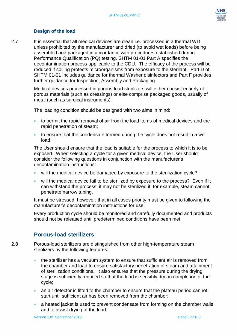
Design of the load
2.7 It is essential that all medical devices are clean i.e. processed in a thermal WD unless prohibited by the manufacturer and dried (to avoid wet loads) before being assembled and packaged in accordance with procedures established during Performance Qualification (PQ) testing. SHTM 01-01 Part A specifies the decontamination process applicable to the CDU. The efficacy of the process will be reduced if soiling protects microorganisms from exposure to the sterilant. Part D of SHTM 01-01 includes guidance for thermal Washer disinfectors and Part F provides further guidance for Inspection, Assembly and Packaging.
Medical devices processed in porous-load sterilizers will either consist entirely of porous materials (such as dressings) or else comprise packaged goods, usually of metal (such as surgical instruments).
The loading condition should be designed with two aims in mind:
to permit the rapid removal of air from the load items of medical devices and the rapid penetration of steam;
to ensure that the condensate formed during the cycle does not result in a wet load.
The User should ensure that the load is suitable for the process to which it is to be exposed. When selecting a cycle for a given medical device, the User should consider the following questions in conjunction with the manufacturer’s decontamination instructions:
will the medical device be damaged by exposure to the sterilization cycle?
will the medical device fail to be sterilized by exposure to the process? Even if it can withstand the process, it may not be sterilized if, for example, steam cannot penetrate narrow tubing.
It must be stressed, however, that in all cases priority must be given to following the manufacturer’s decontamination instructions for use.
Every production cycle should be monitored and carefully documented and products should not be released until predetermined conditions have been met.
Porous-load sterilizers
2.8 Porous-load sterilizers are distinguished from other high-temperature steam sterilizers by the following features:
the sterilizer has a vacuum system to ensure that sufficient air is removed from the chamber and load to ensure satisfactory penetration of steam and attainment of sterilization conditions. It also ensures that the pressure during the drying stage is sufficiently reduced so that the load is sensibly dry on completion of the cycle;
an air detector is fitted to the chamber to ensure that the plateau period cannot start until sufficient air has been removed from the chamber;
a heated jacket is used to prevent condensate from forming on the chamber walls and to assist drying of the load.

SHTM 01-01 Part C
Version 1.0: September 2018 Page 7 of 103
Pressure Systems Safety Regulations
2.9 Requirements of the Pressure Systems Safety Regulations 2000 (amended) should be met. Advice should be sought from the CP(PS). The CP(PS) has three principal duties under the Regulations:
advising on the scope of the written scheme of examination for each pressure vessel;
drawing up the written scheme of examination or certifying the scheme as being suitable;
carrying out examinations in accordance with the written scheme, assessing the results and reviewing the written scheme for its suitability.
The User and AP(D) should co-operate closely with the CP(PS) to ensure that the written scheme of examination is accommodated within the maintenance and testing programmes. The written scheme may require certain examinations to be carried out more frequently than recommended by the manufacturer. Each scheme should include detailed procedures and frequency of examination and be regularly reviewed and updated.
Air removal
2.10 The presence of air in the load can impede the penetration of steam and drastically reduce the effectiveness of the sterilization process. Porous-load sterilizers have an active air removal system in which air is replaced with steam by a series of vacuum and pressure changes. A sterilizer conforming to EN 285 and validated according to the schedule set out in Section 3 ‘Validation and verification’ should be capable of removing sufficient air from packages randomly placed in the chamber and which contain porous material not exceeding the density of the standard test pack.
Where the density of porous material exceeds that of the standard test pack, a thermometric performance qualification (PQ) test is required, see Section 3 ‘Validation and verification’. It may also be necessary to perform microbiological performance qualification tests in the case where thermometric tests may give misleading results. Reference should be made to the BS EN ISO 17665 series and in particular PD ISO/ TS 17665 Part 3:2013 provides further advice on categorization of loads into product families. Further advice may be obtained from an AE(D).
Compatibility of load and process
2.11 Sterilizer operating cycles are designed to cope with differing properties of various types of load. For example a container with a small orifice will also require the duration of each air removal pulse to be extended to allow for pressure equilibration. Otherwise the air will remain in the container and sterilization will not be achieved.
SHTM 01-01 Part C
Version 1.0: September 2018 Page 8 of 103
Sterilization conditions
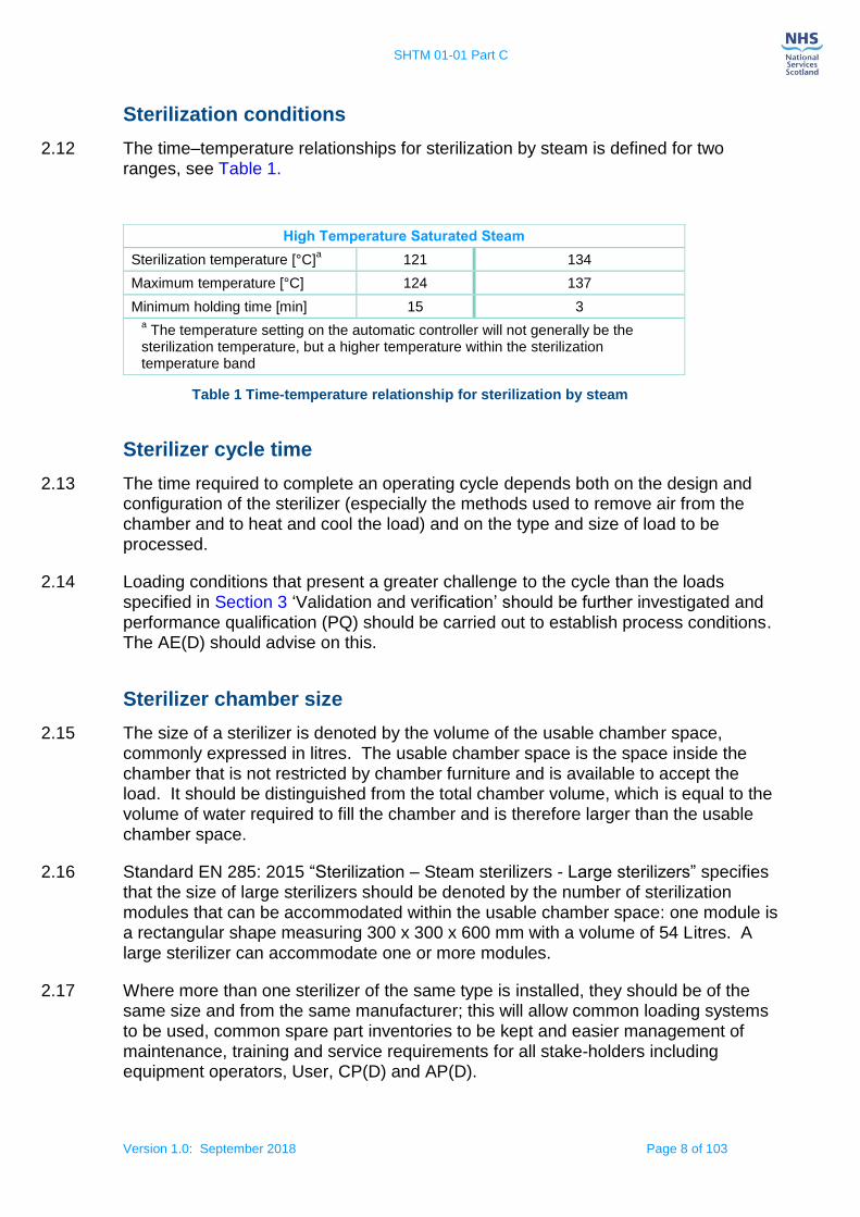
2.12 The time–temperature relationships for sterilization by steam is defined for two ranges, see Table 1.
Table 1 Time-temperature relationship for sterilization by steam
Sterilizer cycle time
2.13 The time required to complete an operating cycle depends both on the design and configuration of the sterilizer (especially the methods used to remove air from the chamber and to heat and cool the load) and on the type and size of load to be processed.
2.14 Loading conditions that present a greater challenge to the cycle than the loads specified in Section 3 ‘Validation and verification’ should be further investigated and performance qualification (PQ) should be carried out to establish process conditions. The AE(D) should advise on this.
Sterilizer chamber size
2.15 The size of a sterilizer is denoted by the volume of the usable chamber space, commonly expressed in litres. The usable chamber space is the space inside the chamber that is not restricted by chamber furniture and is available to accept the load. It should be distinguished from the total chamber volume, which is equal to the volume of water required to fill the chamber and is therefore larger than the usable chamber space.
2.16 Standard EN 285: 2015 “Sterilization – Steam sterilizers - Large sterilizers” specifies that the size of large sterilizers should be denoted by the number of sterilization modules that can be accommodated within the usable chamber space: one module is a rectangular shape measuring 300 x 300 x 600 mm with a volume of 54 Litres. A
large sterilizer can accommodate one or more modules.
2.17 Where more than one sterilizer of the same type is installed, they should be of the same size and from the same manufacturer; this will allow common loading systems to be used, common spare part inventories to be kept and easier management of maintenance, training and service requirements for all stake-holders including equipment operators, User, CP(D) and AP(D).
High Temperature Saturated Steam
Sterilization temperature [°C]a 121 134
Maximum temperature [°C] 124 137
Minimum holding time [min] 15 3 a The temperature setting on the automatic controller will not generally be the
sterilization temperature, but a higher temperature within the sterilization temperature band
SHTM 01-01 Part C
Version 1.0: September 2018 Page 9 of 103
2.18 When planning a department or upgrading an existing facility, consideration should be given to ensuring adequate space is available both in the Plant Room, loading and unloading areas, to allow for:
future replacement, growth of the service and any advancement in technology;
safe access for engineering staff to the sterilizers and steam supply plant (for steam quality tests) for servicing, maintenance and testing purposes.
Specification and contract
2.19 A specification should be completed as part of the procurement process and submitted as part of a legal contract between the purchaser and the manufacturer. It is essential that the procurement specification is prepared by a team of qualified and competent staff and that the AP(D) and AE(D) are consulted during this process.
2.20 Porous load sterilizers should conform to the specifications of EN 285: 2015 and EN 61010-2-040: 2015. Purchasers should refer to SHPN 13 Part 1: 2011, when preparing a specification for a sterilizer.
2.21 Manufacturers should provide certification to the purchaser that the particular design of the equipment is manufactured in conformity with all relevant EU standards, national guidance and regulations. Sterilizers are covered by a number of European Regulations/Directives and are thus required to be in conformance. Relevant Directives include but are not restricted to:
Regulation (EU) 2017/745 on medical devices;
Electromagnetic Compatibility Directive (2014/30/EU),
Low voltage Directive (2014/35/EU);
Pressure Equipment Directive (2014/68/EU) and the;
Machinery Directive (2006/42/EC).
Water services to the sterilizer
2.22 Where multiple units are installed, adequate capacity to prevent starvation of services as a result of other equipment connected to common supplies should be assured. A cold water supply may be needed for equipment such as condensers, heat exchangers and water-sealed vacuum pumps (feed water for steam generation is discussed in Section 4 ‘Steam plant’). Details of the water-quality requirements, the maximum pressure, minimum pressure and maximum flow rate should be obtained from the sterilizer manufacturer.
2.23 Backflow prevention devices should be provided on the water supply as required and need to comply with EN 1717: 2000 and the Water Supply (Water Fittings) (Scotland) Byelaws 2014.
2.24 The temperature of water used for sterilizers with vacuum systems should not exceed the value specified by the manufacturer. Higher water temperatures will reduce the efficiency of vacuum pumps and compromise the specified vacuum levels.

SHTM 01-01 Part C
Version 1.0: September 2018 Page 10 of 103
2.25 Performance will also deteriorate if the water is very hard or contains large quantities of solids in suspension. The hardness of the water should be in the range 0.7–2.0 mmol L–1. Hardness values outside these limits may cause scaling and corrosion problems.
2.26 Water economy devices (for example, those that sense the temperature of cooling water and adjust the flow rate accordingly) should be fitted to reduce water consumption.
2.27 Chlorine and chlorides may cause corrosion of stainless steel in the presence of heat. Advice on maximum permissible levels should be obtained from the sterilizer manufacturer. EN 285 also gives guidance on appropriate feedwater quality.
2.28 Further guidance on water supply is given in Scottish Health Technical Memorandum 04-01 – ‘Water safety for healthcare premises’.
Condensate recovery and sterilizer effluent
2.29 Condensate should be recovered wherever possible, including the steam distribution system, steam separators and chamber jacket, then returned to the steam generation plant, provided the quality of the feed water to the boiler is not compromised or the condensate is not corrosive.
2.30 Effluent can originate from one or more of the following sources:
air, condensate and steam from the chamber drain, which can contain chemicals and microorganisms;
discharge from a water-sealed vacuum pump, ejector or chamber ventwater introduced to cool and dilute the discharge from the chamber.
2.31 As effluent from steam sterilizers and associated equipment is potentially contaminated it should be connected to the main drain in a manner which provides backflow protection and is consistent with Building (Scotland) Regulations 2004 and Sewerage (Scotland) Act 1968 (as amended 2002).
2.32 Where a storage tank supplies water to a water-sealed vacuum pump or a water pump used for an ejector vacuum system, the overflow discharge from the storage tank should also include an air break.
The Plant Room design should consider the safe discharge of vapour from the steam safety valves as fitted to the header, jacket and chamber of sterilizers to a safe exit, and from built in steam generators if fitted. Indication pipes or tails should be installed to ensure that leakage or discharge can be identified. The discharge point should be to outside of the building.
Air detector test
2.33 EN 285:2015 requires that there are methods in place to ensure that the requirement for steam penetration throughout the chamber and load is achieved for each cycle. This should be done by specifying an air detector that will abort the cycle if sufficient air and other non-condensable gases have not been removed from the chamber.

SHTM 01-01 Part C
Version 1.0: September 2018 Page 11 of 103
The correct functioning of the air detector is crucial to the performance of the sterilizer.
2.34 For sterilizers programmed with a separate automatic air detector function test, the test cycle should otherwise replicate the normal production cycle.
Testing for even penetration of steam
2.35 To ensure the rapid and even penetration of steam into all parts of the load for the specified holding time and temperature, it is essential to remove air from the chamber and load, and provide a steam supply that contains a minimal volume of non-condensable gases.
2.36 The Bowie and Dick test is a performance test that indicates rapid and even penetration of steam into a test pack for wrapped goods and porous loads. The test method is described in EN 285: 2015.
2.37 While a successful Bowie and Dick test indicates rapid and even penetration of steam into the test pack it does not necessarily demonstrate either achievement of the required temperature or maintenance of that temperature for the required time to achieve sterilization.
Where the presence of air or non condensable gases within the pack, results in a failure of the test possible causes of the failure may include:
an inefficient air removal stage;
an air leak during the air removal stage or;
non-condensable gases in the steam supply.
A failure of the Bowie and Dick test is not conclusive proof that the fault in the sterilizer is due to air retention, air leakage or non-condensable gases and it can be necessary to investigate other causes of failure.
Port for air-flow metering device
2.38 An air-flow metering device used for testing air detector performance and chamber integrity should be fitted to the test port on the side of the sterilizer, preferably towards the lower front.
Absolute pressure indicator
2.39 For induced leak-testing purposes an absolute pressure indicator (0 to 160 mbar) should be fitted, conforming to EN 285: 2015.
Extended drying cycle
2.40 An additional cycle with extended drying time should be provided to process loads that are difficult to dry. For example heavy metal orthopaedic hammers. Management at each CDU should consider if they wish to set this as a default setting. The parameters of any extended drying cycle should be the same as those used in the normal production cycle with the exception of the drying time.

SHTM 01-01 Part C
Version 1.0: September 2018 Page 12 of 103
3. Validation and verification of the sterilizer
3.1 Sterilization is a process whose efficacy cannot be verified retrospectively by inspection or testing of the product. For this reason sterilization processes should be validated before use. The performance of the process should be monitored routinely, and the sterilization equipment should be maintained in accordance with the manufacturer’s instructions for use.
3.2 Tests and checks should be carried out to ensure sterilizers are fit for purpose during the various stages of manufacture (type tests and work tests – see glossary in SHTM 01-01 Part A), after delivery, during validation (Installation Qualification (IQ), Operational Qualification (OQ) and Performance Qualification (PQ) and safety tests and periodically thereafter. The performance of a sterilizer is tested at different times using different procedures as outlined, see Table 2.
Standard EN 285: Sterilization — ‘Steam sterilizers — Large sterilizers (2015)’ is an equipment standard giving manufacturers the basic requirements for steam processing equipment. The procedures to be performed by the manufacturer during type and works testing in order to confirm acceptable performance are defined in (clause 4 table 5) of EN 285. Where factory acceptance testing is required, a protocol should be agreed in advance with the AE(D) prior to purchase and included in the procurement contract. The responsibility for performing type and works tests will normally rest with the manufacturer. The responsibility for testing once installed on-site is dependent upon contractual agreements and/or purchaser preferences and should be performed by qualified personnel. IQ and OQ tests demonstrate compliance to the requested specification of the standards. Procedures performed upon installation ((IQ), OQ) and (PQ)) are also defined in EN 285 and EN ISO 17665 Part 1: 2006.
3.3 Advice should be sought from an AE(D) with respect to the status of the test procedures described in this guidance.
Schedule of validation (IQ, OQ and PQ) tests
3.4 The contractor should carry out Installation Qualification (IQ) checks and tests before Operational Qualification (OQ) tests are performed; these may be witnessed or repeated by the CP(D) if required.
3.5 OQ tests and Performance Qualification (PQ) tests should be carried out by the CP(D).
3.6 PQ tests should be carried out after the IQ and OQ tests have been satisfactorily completed. PQ tests may be performed while the sensors used in the IQ and OQ tests are still in place and before the final vacuum leak test.

SHTM 01-01 Part C
Version 1.0: September 2018 Page 13 of 103
3.7 A schedule for all validation tests is shown, see Table 2. The tests should be carried out with the equipment at normal working temperature, which may require a warm up cycle prior to testing.
TEST IQ OQ PQ
Commissioning safety checks and tests
X
Non-condensable gas test X
Steam dryness test X
Steam superheat test X
Steam contaminants X
Air leakage test X X
Air leakage test after insertion of sensors into a chamber
X
Automatic control test X X
Verification of calibration* X X
Thermometric test for a small load* X
Thermometric test for a full load X
Air detector performance test for a small load
X
Air detector performance test for a full load
X
Thermometric performance qualification tests (where required by the User)
X
Air leakage test after removal of any sensors into a chamber
X
Hollow load test X
Bowie and Dick test for steam penetration*
X
Air detector function test X
Load dryness – small load textiles X
Load dryness – full load textiles X
Load dryness – metal (where required by the User) (see EN 285)
X
Production load dryness test X
* The automatic control test may be carried out at the same time as these tests.
Table 2: Validation tests for a porous load sterilizer at the IQ, OQ and PQ stages
Unless specified otherwise, all the tests should be performed at each of the sterilization temperatures available on the sterilizer.
Installation checks
Checks on ancillary equipment
3.8 Ancillary equipment should ideally be installed and commissioned before the

SHTM 01-01 Part C
Version 1.0: September 2018 Page 14 of 103
validation procedure for the sterilizer begins. When the checks on ancillary equipment require a sterilizer to be in operation, the CP(D) should carry them out in co-operation with the contractor for the sterilizer.
3.9 The contractor responsible for the installation of sterilization equipment is not responsible for the correct functioning of services and ancillary equipment unless this was agreed in the purchase contract.
Engineering services
3.10 Checks should be made on the following:
that the engineering services are installed correctly, are adequate to meet the demands of the decontamination equipment, do not leak, and all necessary isolating valves or switches and test points have been installed and are working correctly;
that drains remove effluent effectively when all plant in the vicinity, including the decontamination equipment, is connected and operating under full demand;
that the water treatment plant (if fitted) operates correctly and that the quality of water supplied for each stage of the process is in accordance with the specification;
that the water economy system (if fitted) operates correctly.
Note: Installation tests should determine and provide documented evidence that the porous load sterilizer is installed and configured to operate in a safe manner and is
manufactured, installed and operates in accordance with EN 61010-2-040:2015.
3.11 Electrical equipment on the sterilizer should be checked to ensure it is correctly connected to the electrical service in accordance with BS 7671: 2015 (IET Wiring Regulations). The following electrical tests should be carried out and certified:
insulation resistance;
phase sequence (for three-phase installations);
polarity;
bonding and earth continuity;
emergency stop.
3.12 After the sterilization equipment has been installed, it should be checked to ensure that the following recommendations are met:
the manufacturer has supplied all the documents specified in the contract;
the equipment has been supplied and installed in accordance with the contract;
calibration verification certificates traceable to UKAS certification for the measuring instruments and controller(s) on the equipment have been supplied;
no defects are apparent from a visual inspection of the equipment;
all supports, bases and fixings are secure and without imposed strain from service connections;

SHTM 01-01 Part C
Version 1.0: September 2018 Page 15 of 103
thermal insulation is in good condition and securely attached;
keys, codes or tools required to operate locked controls and control over-rides have been supplied, operate correctly and only operate the control for which they are intended; and cannot unlock controls on other machines in the vicinity;
loading conveyors and trolleys, load carriers and load baskets are effective and safe in use;
IT connections are made and connected for the sterilizer system and monitoring instrumentation onto the main server and available for back-up;
security and settings of door safety switches are in compliance with data supplied by the manufacturer.
Installation Qualification (IQ) tests
3.13 The Installation Qualification testing is a process of obtaining and documenting evidence that the equipment and ancillary services have been provided and installed in accordance with the specification supplied to the manufacturer.
After installation and when all commissioning and safety checks have been completed Installation Qualification tests should be carried out with an empty sterilizer and should consist of:
an air leakage test;
an Automatic control test;
verification of calibration.
These tests also form part of the OQ and are described in detail in Section 3 -Validation and verification.
Operational Qualification (OQ) functional checks
3.14 During an operating cycle, with an empty chamber, checks should be made that the following recommendations are met (several cycles may be necessary to complete all the checks):
the selection of automatic or manual control is by key code or tool;
the selection of one control mode inactivates the other control mode;
water, steam or compressed air cannot be admitted into the chamber when the equipment is under automatic control until the door is closed, locked and sealed;
the operating cycle cannot start until the door is closed, locked and sealed;
the cycle may be advanced sequentially under manual control – this function should be protected by password/code entry/keyswitch;
the indicated and recorded values of cycle variables are within the limits specified by the manufacturer throughout the cycle;
there are no leaks of water, steam aerosols, air, gas or effluent throughout the cycle;
SHTM 01-01 Part C
Version 1.0: September 2018 Page 16 of 103
there is no evidence of interference to or from other equipment connected to the same services;
operation and reading of all instruments appears to be satisfactory;
the temperature of surfaces routinely handled by the operator does not exceed 43ºC;
a means of diluting/reducing any high temperature effluent to <43oC is required prior to discharge into any water company common drains.
3.15 At the end of the cycle, checks should be made that the following recommendations are met:
the door opening system cannot be operated until the cycle has been completed;
for systems incorporating one or more cycle stages at pressures 200 mbar above or below atmospheric pressure:
the door opening system cannot be operated until the chamber has been vented to atmosphere and the chamber pressure is within 200 mbar of atmospheric pressure;
the door retainers cannot be released until the seal between the door and chamber has been broken, and the chamber is effectively vented to atmospheric pressure.
each door interlock system is fail-safe;
failure of one interlock, or any one service, does not allow the door to be opened when conditions within the chamber would cause a hazard, for example pressure in excess of 200 mbar;
the automatic controller has operated in accordance with the specification.
Sterilizer response to external faults
3.16 The sterilizer should be checked to ensure it reacts correctly and safely, that is, it does not create a safety hazard or give a false indication of the satisfactory completion of a cycle, when exposed to a number of external fault conditions.
3.17 During each stage of an operating cycle, the response of the sterilizer to the following simulated faults (as appropriate to the type of machine) should be checked, ensuring that the cycle will fail in the event of each fault:
operation of the emergency stop button;
power failure;
steam pressure too low;
steam pressure too high;
compressed air pressure too low;
compressed air pressure too high;
water service failure;
communication failure.

SHTM 01-01 Part C
Version 1.0: September 2018 Page 17 of 103
Performance Qualification (PQ) tests
3.18 Performance Qualification (PQ) is the process of obtaining and documenting evidence that the sterilizer will consistently provide reproducible results when operated in accordance with the pre-defined acceptance criteria within the process specification. PQ tests should be performed as part of the validation procedure, as part of any repeat validation procedure, and whenever the User judges that a new loading condition calls for a new PQ test. It is the responsibility of the User to set the acceptance criteria to allow the steam processing equipment and sterilizer to be validated during PQ testing. Standard EN ISO 17665 Part 1 and technical specification CEN ISO/TS 17665 Part 2 describe how this should be carried out.
3.19 PQ tests (or commissioning tests providing PQ data) collect three different types of data, indicated, recorded and measured. The three sets of data serve different purposes and may require different tolerances:
indicated data (electronic displays etc.) are available as a general guide to the user for monitoring production cycles during operation on all types of sterilizer;
recorded data are available to the user for production cycles on most types of sterilizer and can be regarded as definitive proof for routine production control and product release;
measured data obtained during OQ and PQ testing is regarded as definitive proof of sterilizer efficacy for the purposes of validation as they are more reliable than indicated or recorded values. The permitted tolerances should reflect this.
3.20 PQ data can be generated for single load conditions or conditions representative of pre determined product families. Where the PQ data is to be used for loads requiring specific conditions (e.g. medical devices that would be damaged if the limits were broader) any recorded variation between cycles should be small and due to the performance limits of the sterilizer) and the permitted tolerances should be tight. Replicated thermometric PQ tests should give some indication of acceptable variation.
3.21 Where the PQ data for a single loading condition is judged to be valid for a range of loading conditions (e.g. for a product family), the variation between cycles will contain a systematic variation related to the differing loading conditions, and the permitted tolerances will be greater. The choice of loading conditions for which the data is valid should take into account whether this greater tolerance is acceptable.
3.22 The extent of the PQ required will depend on the type of sterilizer and the nature of the load. The initial PQ load should be accurately documented to enable replication at yearly revalidation. Where a new load is not covered by an existing PQ report, full
PQ tests should be conducted.
3.23 Users should adopt the following procedure for every sterilizer:
establish a list of potential product families and their relationship to the validation loads (see CEN ISO/TS 17665-2: 2009 Sections 6 and 9 and PD ISO/TS 17665 Part 3:2013);
establish a list of the different loading conditions to be processed in the sterilizer. Each production load should correspond to one of the listed loading conditions;

SHTM 01-01 Part C
Version 1.0: September 2018 Page 18 of 103
determine whether each loading condition presents a greater or lesser challenge to the process than the small and full loads used in the thermometric tests carried out during validation;
where the loading condition is a lesser challenge than the validation loads, the results of the validation tests may be used as PQ data;
where the loading condition is a greater challenge than the validation loads, additional PQ tests should be carried out.
3.24 Technical specification PD ISO/TS 17665, Part 3 gives guidance on how to assign medical devices to product families allowing medical devices presenting a similar challenge to be approved by one PQ test, reducing the number of PQ tests required.
3.25 When setting the specifications for a new sterilizer, the User should ensure that details of the product families to be processed are identified, including weights and
sterile barrier systems to be used. This will allow the manufacturer to assess whether their sterilizer is capable of processing the load during factory acceptance testing and prior to purchase.
3.26 The User with advice from the AE(D) should decide which loading conditions require PQ tests for each sterilizer. PQ tests are required where:
the density of any packaged medical device exceeds the density of the standard test pack;
the mass of any single metal item exceeds 1 kg;
the construction of any packaged medical device is such that sufficient air may not be removed to ensure the rapid penetration of steam;
any cycle variable that have been modified from the setting used during validation;
three categories require special consideration:
minimally invasive medical devices (such as laparoscopic biopsy forceps) which present particular problems of air removal and steam penetration;
barrier fabrics (such as breathable membranes) which have such low porosity to both air and steam that normal air removal stages may be inadequate;
medical devices with insulated lumens such as cannulated screwdrivers.
3.27 When designing a new loading condition, it is important that the correct packaging is specified with the load. The packaging specification and materials should be to the appropriate standards and not altered without repeating the PQ procedure unless the loading condition with new packaging can be demonstrated to be covered by an existing PQ report. Refer to SHTM 01-01 Part F for further guidance of packaging systems.
3.28 In cases of doubt, advice should be sought from the AE(D).

SHTM 01-01 Part C
Version 1.0: September 2018 Page 19 of 103
Thermometric tests for PQ
3.29 Temperature sensors should be as described in SHTM 01-01 Part B.
3.30 The packaged medical devices that are fastest and slowest to heat up should have been identified as part of the design of the loading condition. Sensors should be in good thermal contact with the medical device they are monitoring and be placed in contact with the part that is slowest to heat up.
3.31 PQ tests are used to establish the level of performance expected for a particular operating cycle combined with a specific loading condition. This gives a benchmark for comparison with subsequent production cycles. Tolerances are normally expressed as a permitted variation above a specified minimum value.
3.32 When setting the tolerances, careful consideration should be given to the likely
variation from cycle to cycle. If the tolerance levels are set too narrowly, acceptable production loads may be mistakenly rejected as non-sterile and automatic control and PRQ tests may fail unnecessarily. If tolerance levels are set too widely, it may disguise variations signalling a developing malfunction of the sterilizer. The AE(D) should be consulted in these matters.
3.33 Data from the thermometric commissioning tests are used to establish performance standards for a wide range of loading conditions. In these cases, data from the small-load and full-load tests should be used to establish the limits of variation for production loads that fall between these two extremes.
Method for the thermometric test for PQ
3.34 Place a sensor in the reference measurement point i.e. the point where the cycle control temperature sensor is located.
Additional temperature sensors should be placed in the following positions:
one on/in each of three packaged medical devices that are slowest to attain the sterilization temperature;
one on/in each of three packaged medical devices that are fastest to attain the sterilization temperature;
if the load consists of fewer than six packaged medical devices, one on/in each;
if the load includes medical devices with lumens, temperature sensors should be placed to monitor the environment within the lumen at the most challenging position rather than on the outer surface. In cases where temperature cannot be used to determine the presence of residual air (for example, a narrow lumen or metal medical device in which the residual air rapidly attains steam temperature), alternative sensor technology should be used. Examples include chemical and biological indicators.
3.35 Record the loading condition and the positions of the sensors and probes in sufficient detail to allow the test to be replicated. Digital photography provides a useful record for this purpose.
3.36 Connect a pressure recorder or pressure-recording instrument to the chamber.
SHTM 01-01 Part C
Version 1.0: September 2018 Page 20 of 103
3.37 Select the operating cycle that will be used for the production load.
3.38 Start the cycle.
3.39 The test should be considered satisfactory if the following requirements are met:
the holding time, as determined from the measured temperatures, is not less than that specified in Table 1;
throughout the holding time:
the temperature measured at the reference measurement point of the sterilizer chamber, any temperature measured within the test pack, load and chamber, and the saturated steam temperature calculated from the measured chamber pressure should be within the sterilization temperature band (e.g. 134 to137ºC for a minimum of 3 minutes) and not differ from one another by more than 2ºC;
the indicated and recorded temperatures from the chamber and load of packaged medical devices are within 2ºC of the temperature measured at the reference measurement point, and not differ from one another by more than 2ºC;
the indicated and recorded chamber pressures are within 0.05 bar of the measured pressure;
at the end of the cycle the temperature sensors have remained in position.
3.40 If the test is satisfactory, it should be performed twice more to check for reproducibility and establish permitted tolerances. If the sterilizer fails to meet the requirements of the test, it is possible that the sterilizer is not capable of processing the load or presentation of the load requires changing (for example a different sterile barrier system combination or tray). Advice should be sought from the AE (D).
Microbiological test for PQ
3.41 The microbiological test should ideally follow a satisfactory thermometric test, using the identical loading condition and operating cycle. This test is designed to be used in exceptional circumstances as an additional PQ test for steam sterilizers. There may be situations where thermometric tests are not possible, for example, with medical devices with narrow lumens, where it is not physically possible to place a thermocouple or temperature sensor into the lumen without altering the nature of the load. Reference should be made to EN 556-1: 2001 for sterility assurance requirements.
Result
3.42 The test should be considered satisfactory if the following requirements are met:
during the whole of the cycle the values of the cycle variables as shown on the batch processing record (BPR) are within the permitted tolerances marked on the master processing record (MPR) established during the thermometric PQ test;
the requirements for microbiological tests are met.

SHTM 01-01 Part C
Version 1.0: September 2018 Page 21 of 103
Use of biological indicators
3.43 Biological indicators are designed to show whether specified sterilization conditions have been attained by the survival of test microorganisms. However, they should not be used for routine monitoring of steam sterilization processes. In exceptional circumstances where the use of biological monitors could be considered, advice should be sought from the Microbiologist (Decontamination).
3.44 When biological indicators are required, those specified in EN ISO 11138 Part 3: 2017 should be used. These will usually be Geobacillus stearothermophilus. Advice
on selection, use and interpretation of results when using biological indicators can be found in ISO 14161: 2009.
3.45 After use, the biological indicators should be recovered according to the manufacturer’s instructions.
3.46 Biological indicators should be cultured in accordance with the manufacturer’s instructions for use.
Automatic control test
Introduction
3.47 The automatic control test is designed to show that the operating cycle functions correctly as shown by the cycle variables indicated and recorded by the decontamination equipment.
3.48 It should be carried out weekly and is one of the tests for ensuring that the sterilizer continues to function correctly.
3.49 During the validation, quarterly and yearly test programmes the temperature and pressure sensors for subsequent thermometric tests should be connected to the chamber during this test. If a sensor is placed adjacent to each of the sensors connected to the installed temperature measuring instruments, the calibration of these instruments may be checked during periods of stable temperature in the automatic control test.
Apparatus
3.50 For porous-load sterilizers place a test pack in the chamber, with the bottom of the pack supported 100–200 mm above the centre of the chamber base.
Method
3.51 Select the operating cycle to be tested. This should normally be the highest temperature compatible with the load. Start the cycle.
3.52 Ensure that a Batch Processing Record (BPR) is made by the recording instrument fitted to the machine.
Results
3.53 The test should be considered satisfactory if the following requirements are met:

SHTM 01-01 Part C
Version 1.0: September 2018 Page 22 of 103
a visual display indicating “cycle complete” occurs;
the values of the cycle variables, as indicated by the instruments on the machine or shown on the BPR, are within the limits established as giving satisfactory results either by the manufacturer or during PQ, during the whole of the operational cycle;
during the plateau period determined from the recorded chamber temperature:
the indicated and recorded chamber temperatures are within the appropriate sterilization temperature band specified in Table 1;
the difference between the indicated, recorded and any other independent monitor chamber temperature does not exceed 2ºC;
the difference between the indicated, recorded and any other independent monitor chamber pressure does not exceed 0.1 bar;
during the holding time, any temperatures recorded in the load are within the appropriate sterilization temperature band specified in Table 1;
the door cannot be opened until the cycle is complete;
the person conducting the test does not observe any mechanical or other anomaly.
3.54 The sterilization conditions are specified by a sterilization temperature band, defined by a minimum acceptable temperature (sterilization temperature) and a maximum allowable temperature. These are listed in Table 1.
3.55 Where an independent monitoring system is employed that has the necessary data-processing capability, process variability may be monitored automatically through presentation of suitable control charts displaying critical process data (for example, vacuum and pressure set points on each pulse, and average, minimum and maximum temperatures and pressures during the sterilization hold phase).
Air leakage test
3.56 The air leakage test is applicable to any sterilizer that employs vacuum to remove air from the load.
3.57 This test should be carried out weekly in accordance with EN 285: 2015 clause 18.
3.58 This test is commonly referred to as the ‘vacuum leak test’ or ‘leak rate test’.
3.59 The test is designed to establish the air tightness of the chamber and that permissible limits are not exceeded. If the sterilizer is not fitted with an instrument to measure the air leakage, connect a 0-160 mbar absolute gauge to a chamber port with an isolation valve. For the test to be satisfactory the chamber temperature should be stable, hence the air leakage test should be preceded by a warm up cycle.
3.60 The test can be operated under manual control by an engineer to establish criteria of the test or for investigations of the sterilizer. Operational tests and periodic tests are usually carried out under automatic cycle control.

SHTM 01-01 Part C
Version 1.0: September 2018 Page 23 of 103
3.61 Select the correct cycle and start the test. Under the cycle, the chamber pressure is evacuated to a predetermined set point. The set point would have been established during validation or checked at annual testing. The initial vacuum should achieve absolute pressure in the chamber of less than 70mbarA (7kPa).
3.62 When the set point is reached, the machine will stop the vacuum pump and close the appropriate chamber valves: a predetermined 5 minute stabilization period begins following which readings are taken.
3.63 The predetermined hold stage is measured at the start and finish of the subsequent 10 minute period. Once the 10 minute is complete the chamber is vented to atmospheric pressure.
3.64 The test is deemed a pass if the pressure increase does not exceed 13mbar (1.3kPa) in the 10 minute hold period.
Note: If using sensors that require a through chamber connection and/or a pressure sensing device that requires a connection to the chamber, they should be introduced into the chamber via a purpose designed entry gland and suitable fittings.
A typical sensor entry gland is shown, see Figure 1. (SHTM 01-01 Part B provides the requirements for test equipment including sensors).
This gland is fitted after the initial air leakage test and the air leakage test should be undertaken again after the gland and sensors have been fitted to the chamber port.
Figure 1 shows a fitting designed for a sterilizing chamber having a male gland and an ‘O’ ring seal, see key 8 in Figure 1. When the gland is a female thread an adaptor, see key 6 in Figure 1 will be required.
Other methods of introducing temperature sensors into a sterilizer chamber and which guarantee a gas-tight seal are equally acceptable.
Care should be taken with the sensors so that they are not damaged when fitted.

SHTM 01-01 Part C
Version 1.0: September 2018 Page 24 of 103
Figure 1: Typical sensor entry gland
Air detector function test
3.65 This test should be carried out weekly in accordance with EN 285: 2015 clause 19. An air detector is a requirement for porous load sterilizers. It is used to determine whether any air or non-condensable gas present in the chamber is sufficient to impair the sterilizing process.
3.66 The air detector should cause a fault to be indicated if the amount of air or gas in the chamber at the start of the plateau period is sufficient to depress the temperature in the centre of the load by more than 2ºC below the temperature in the active chamber discharge.
3.67 The tests can be divided into two types:
the air detector performance test, used to set up and check the continued suitability of the air detector settings
the air detector function test used to check correct functioning of the air detector once it is correctly adjusted.
3.68 A number of repeat tests may be required in order to establish the air leakage rate required. The maximum leak used should be 10 ± 1 mbar/min (1.0 ± 0.1 kPa/min for small and full load air detector tests) in accordance with EN 285: 2015 (clause18).

SHTM 01-01 Part C
Version 1.0: September 2018 Page 25 of 103
3.69 During validation (IQ and OQ) testing, the manufacturer should advise on the initial air leakage value and set points for the air detector.
3.70 Once a satisfactory result for a small load is achieved, the large load should be tested. This will ensure that the air detector will fail a cycle under normal operational conditions from the small load to a full production load, yet still be sterilizing the medical devices in the chamber.
3.71 The air detector function test shall use the same induced leak and set point as determined at initial validation.
3.72 All results must be recorded. This will include depression results, set points and the induced leak applied to the chamber.
3.73 An air flow metering device such as a needle valve capable of controlling the flow of
air into an evacuated chamber is required. Its position and the alarm settings should be recorded in the validation/periodic test report for future reference.
3.74 Small or full load performance tests are carried out on the pre-set and validated porous load cycle. If any significant parameters are changed to improve the air removal, tests should be repeated until a satisfactory performance is reached.
3.75 A small load test is carried out with a single test pack in the chamber.
3.76 Full load performance tests use a full textile load (linen) as described in EN 285:2015 (clause 23.4).
3.77 The air is admitted into the chamber via the needle valve(s) at the predetermined induced leak rate. This may be performed automatically by a pre-determined cycle or by a manual means.
3.78 If a separate automatic cycle is used for the air detector performance or function tests then all cycle parameters must be identical to those used for the production cycle, except for operation of the air metering device and associated vacuum measurement system.
Method
3.79 Start the correct cycle for the test. If a manual test is being performed, open the needle valve or metering device at the pre-set value and air will be admitted into the chamber during the air removal stage. On some types of sterilizer the air detector may need to be switched off for this test.
3.80 The test is satisfactory if, at the start of the plateau period, the lowest temperature measured in the test pack is not more than 2ºC lower than the temperature measured at the reference measurement point (usually the drain sensor).
Standard test pack
3.81 The Standard Test Pack described in EN 285 (clause 23.1) is used for the Thermometric test, for the Bowie and Dick test, small and large load thermometric tests, air detector tests and load dryness tests. This test pack is used to check that,

SHTM 01-01 Part C
Version 1.0: September 2018 Page 26 of 103
at the levels at which the process variables are set, rapid and even penetration of steam into the pack is attained.
3.82 The test pack shall be made up of plain cotton sheets, approximately 900 mm x 1200 mm in size. They should be bleached and washed to remove soil and resin when new and subjected to regular washing to ensure consistent results for the testing. No fabric conditioner should be used.
3.83 The number of threads per centimetre in the warp shall be 30 +/- 6 and number of threads per centimetre in the weft 27 +/- 5; the weight shall be 185 +/- 5 grams/metre2.
3.84 The sheets should be folded to approximately 220 mm x 300 mm and stacked to a height of 250 mm when compressed by hand. The sheets should be folded into 16 layers (folded 4 times). The pack shall be wrapped in a similar fabric and secured with tape not exceeding 25 mm in width. This will usually utilize 30 sheets depending on their age and use.
3.85 The pack should weigh 7.0 kg +/- 0.14 kg.
3.86 When the weight of the sheets to form a stack of 250 mm exceeds 7.2 kg, then a new test pack should be used and the old ones discarded.
3.87 Test packs comprising different materials, sizes and weights can be used provided equivalence with the requirements for the test is met.
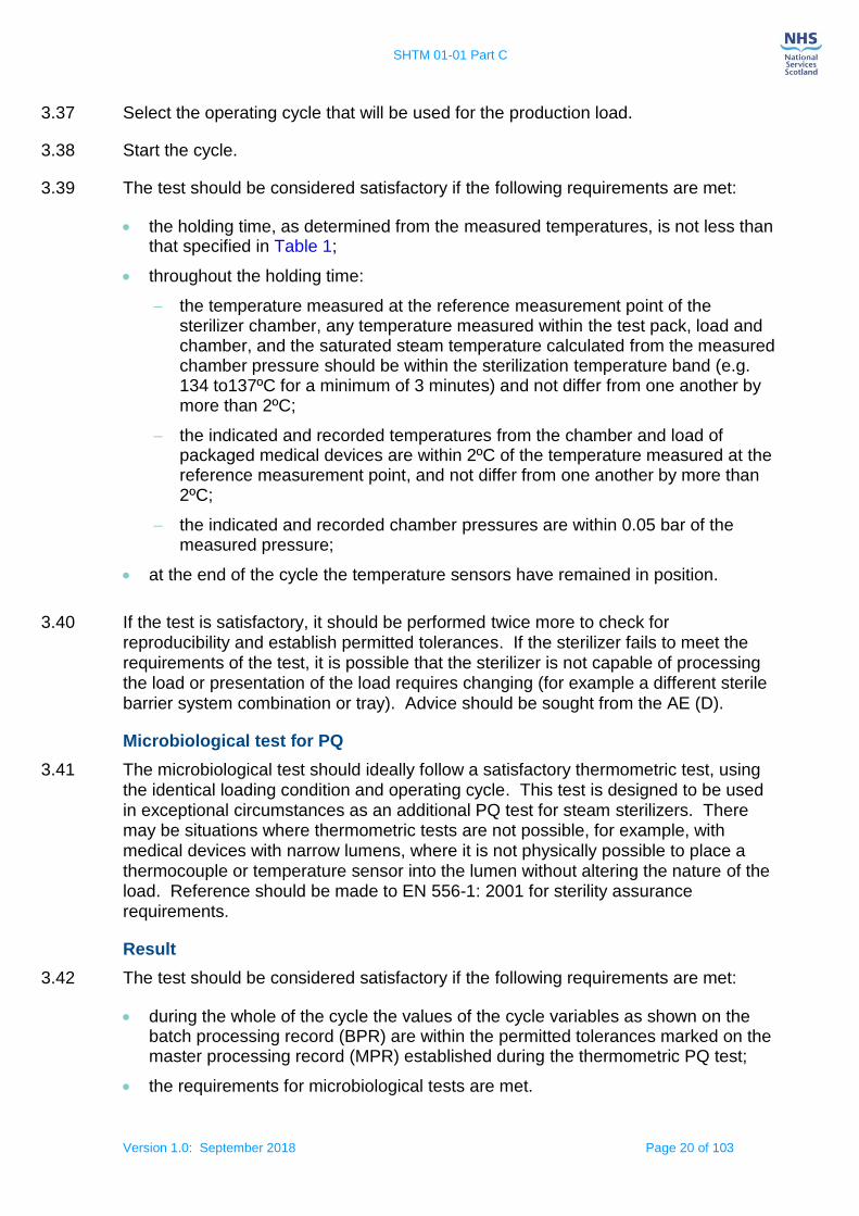
3.88 The test pack is used by itself in an otherwise empty chamber (that is, excluding a carriage etc.). The test pack should be supported 100–200 mm above the chamber base on a carrier with minimal thermal mass, i.e. DIN basket or small metal tray placed across the chamber rails. The position of the standard test pack in a porous load sterilizer with sensors is illustrated, see Figures 2 and 3. The test pack position shown should be used for automatic control, small load thermometric and air detector function tests.
SHTM 01-01 Part C
Version 1.0: September 2018 Page 27 of 103
Figure 2: A standard test pack positioned in the chamber on a basket or small tray
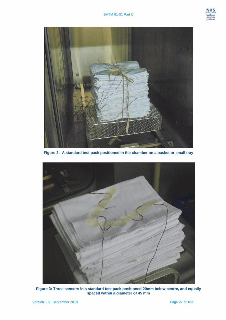
Figure 3: Three sensors in a standard test pack positioned 20mm below centre, and equally spaced within a diameter of 45 mm

SHTM 01-01 Part C
Version 1.0: September 2018 Page 28 of 103
Thermometric test methods
3.89 This test is used to demonstrate that after the air removal stage of the operating cycle, sterilizing conditions are obtained within the chamber and standard test pack. The more air there is to remove, the more exacting will be the test; therefore the Small Load Thermometric test should be carried out in accordance with EN 285: 2015 (clause 16.1).
3.90 The thermometric test shall be conducted using the standard test pack as described in EN 285: 2015 (clause 23) and outlined in paragraph 3.81 of this guidance. Thermometric tests for a small load should be carried out Quarterly.
3.91 Prior to use the test pack should be allowed to normalize to the local environmental conditions and the temperature and humidity of the pack measured using a suitable calibrated temperature and humidity probe. The conditions within the pack should be between 20 °C to 30 °C and 40 % to 60 % relative humidity before it is used for test purposes. Pack temperature and humidity can be measured using a sword hygrometer.
Figure 4: Sensor positions in a standard test pack
Notes on sensor positions:
For an illustration of the positions of all the sensors within the standard test pack, see Figure 4.
Sensor 1: Chamber drain/reference measurement point.

SHTM 01-01 Part C
Version 1.0: September 2018 Page 29 of 103
Sensor 2: Centre of test pack.
Sensors 3, 4, 5: 20 mm below centre at 45 mm diameter spacing.
Sensor 6: 30 mm below centre of pack.
Sensor 7: 50 mm above the test pack.
Thermometric testing: additional information
3.92 A standard temperature profile which is typical of results obtained using the test equipment recommended in SHTM 01-01 Part B is shown, see Figure 5. In practice there may be more temperature traces depending on the number of sensors used. The detailed behaviour before and after the plateau period is dependent on the nature of the operating cycle and is not shown here.
Figure 5: Temperature and time tolerances during the small load thermometric test
3.93 The equilibration time t2 begins when the temperature in the reference point (that is,
the point where the cycle control temperature sensor is situated) first attains the sterilization temperature Ts. It ends when the holding time t4 begins.
3.94 The holding time t4 begins when the temperature in the part of the load that is the slowest to heat up first attains the sterilization temperature Ts. It ends at the start of
the drying stage, when the temperature in the coolest part of the chamber falls below the sterilization temperature.
3.95 The fluctuation in a trace over a given interval is ±TºC if the difference between the maximum and minimum values is 2T°C.
3.96 The drift in a trace over a given interval is the change in the mean value of the trace over that interval.
SHTM 01-01 Part C
Version 1.0: September 2018 Page 30 of 103
3.97 The difference between two traces is the difference in their values at a given instant. A trace is said to be within T ºC of a given value or another trace if the difference between them at any instant over a given interval is no more than T.
Results
3.98 The test should be considered satisfactory if the following requirements are met:
the requirements of the automatic control test are met;
during the plateau period the temperature measured above the test pack does not exceed the temperature measured at the reference measurement point of the sterilizer chamber by more than 5°C for the first 60 s and 2°C for the remaining period, see Figure 5;
the equilibration time shall not exceed 15 s for sterilizer chambers up to 800 litre usable space and 30 s for larger sterilizer chambers;
the holding time, as determined from the measured temperatures, is not less than that specified in Table 1;
throughout the holding time:
the temperature measured at the reference measurement point of the sterilizer chamber, any temperature measured within the test pack, load and chamber, and the saturated steam temperature calculated from the time-averaged measured chamber pressure, see Appendix A, should be within the appropriate sterilization temperature band specified in Table 1, and should not fluctuate by more than ±1°C, or differ from one another by more than 2ºC;
the indicated and recorded chamber temperatures are within 1ºC of the temperature measured at the reference measurement point;
the indicated and recorded chamber pressures are within 0.05 bar of the measured pressure;
for sterilizers using vacuum as the sole method of drying;
the duration of the drying stage is not less than 3 minutes;
the chamber pressure at the end of the stage does not exceed 40 mbar absolute;
at the end of the cycle the sheets are sensibly dry.
Thermometric test for a full load
3.99 The full-load test is designed to demonstrate that, at the levels at which cycle variables are set, rapid and even penetration of steam into the centre of a load occurs, and the sterilizing condition is achieved in a test load of specified maximum mass and of sufficient size to fill the usable chamber space.
3.100 This test should be carried out yearly in accordance with EN 285: 2015 clause 16.2.
Note: temperature sensor positions are according to Figure 4, except sensor 7 which is positioned below the centre of the top sheet of the test pack.
SHTM 01-01 Part C
Version 1.0: September 2018 Page 31 of 103
Results
3.101 The test should be considered satisfactory if the following requirements are met:
the requirements of the automatic control test are met;
during the plateau period the temperature measured above the standard test pack shall not exceed the temperature measured at the reference measurement point of the sterilizer chamber by more than 5°C for the first 60 s and 2°C for the remaining period, see also Figure 5;
the equilibration time shall not exceed 15 s for sterilizer chambers up to 800 l usable space and 30 s for larger sterilizer chambers;
at the end of the equilibration time, the temperature measured at the reference measurement point of the sterilizer chamber and the temperature measured at the nominal geometric centre and below the top sheet of a standard test pack, see 3.81 located in the test load shall be within the sterilization temperature band;
the holding time, as determined from the measured temperatures, is not less than that specified in Table 1;
throughout the holding time:
the temperature measured at the reference measurement point of the sterilizer chamber, any temperature measured within the test pack, load and chamber, and the saturated steam temperature calculated from the time-averaged measured chamber pressure, see Appendix A, should be within the appropriate sterilization temperature band specified in Table 1, do not fluctuate by more than ±1°C, and do not differ from one another by more than 2ºC;
the indicated and recorded chamber temperatures are within 1ºC of the temperature measured at the reference measurement point;
the indicated and recorded chamber pressures are within 0.05 bar of the measured pressure;
at the end of the cycle the sheets are sensibly dry.
Load dryness tests
Load dryness – small & full load textiles
3.102 This test is used to demonstrate that the operating cycle, without extended drying, will not cause an increase in moisture in a standard test pack sufficient for there to be uncertainty about the dryness of loads routinely processed. This test should be carried out yearly in accordance with EN 285: 2015 clause 20, or where problems are experienced with the condition of the load and test pack. Advice should be sought from the AE(D) regarding the metal load dryness test.
Production load dryness test
3.103 Process a production load that is known to present the greatest challenge to the operating cycle. Extended drying may be required.

SHTM 01-01 Part C
Version 1.0: September 2018 Page 32 of 103
3.104 The check should be considered satisfactory if a ‘cycle complete’ indication is obtained and the load is sensibly dry.
Bowie and Dick test for steam penetration
3.105 The Bowie and Dick test was conceived as a test for successful air removal for porous load sterilizers. A successful Bowie and Dick test indicates rapid and even penetration of steam into the test pack.
3.106 A Bowie and Dick type test should be carried out at the start of each day and production should not begin until the test has been shown to be satisfactory.
Principle of the test
3.107 The Bowie and Dick test is described in detail in the European standard EN 285 and
involves a test in which a pre-printed Class 2 chemical indicator sheet complying with EN ISO 11140-3: 2009 is used in conjunction with a standard test pack. Alternative indicators for use in the Bowie and Dick type tests are specified in EN ISO 11140-4: 2007. These indicator systems are designed to show a failure when, at the start of the holding time, the temperature at the centre of the test pack is 2ºC or more below the temperature in the active chamber discharge caused by the presence of residual air. Manufacturers’ instructions should always be followed.
3.108 For convenience it is common to use commercially produced Bowie and Dick test packs/devices for conducting the daily test. Manufacturers’ instructions should be followed.
Bowie and Dick test procedure
3.109 The Bowie and Dick test is normally preceded by a warm-up cycle to ensure the effectiveness of air removal which is depend on all parts of the sterilizer being at working temperature. Conducting a warm-up run will also clear the steam supply system of any non-condensable gases that have accumulated during periods when the sterilizer is unused.
3.110 Remove the wrapping from a standard test pack and place an indicator sheet compliant with EN ISO 11140-3 in the centre of the pack. Reassemble and secure the pack and replace the wrapping.
3.111 Alternatively, prepare the commercially produced Bowie and Dick test pack/device as directed by the manufacturer’s instructions.
3.112 Place the prepared test pack) in the chamber, with the bottom of the pack supported
100–200 mm above the centre of the chamber base.
3.113 Select the Bowie and Dick test cycle. The range of acceptable hold time is specified, see Table 3. Start the operating cycle.

SHTM 01-01 Part C
Version 1.0: September 2018 Page 33 of 103
Table 3: Holding time range for the Bowie and Dick test cycle
3.114 If a holding temperature other than that specified in Table 3 is specified by the manufacturer of the indicator sheet or alternative Bowie and Dick test pack/device, particular care should be exercised. When selecting Bowie and Dick test cycles with a sterilizing temperature of 121°C ensure that the holding time specified by the pack manufacturer is used as these may be far shorter than normal production holding times.
3.115 During the holding time, note the reading on the cycle counter, the chamber temperature indicator and the chamber pressure indicator.
3.116 When the cycle is complete, remove the indicator paper from the test pack and record the result, or record the result from the test device according to the manufacturer’s instructions.
3.117 The test should be considered satisfactory if the following requirements are met:
there is a uniform colour change throughout the indicator sheet or the alternative test device gives a response indicative of a satisfactory result according to manufacturer’s instructions;
the automatic controller indicates that a Bowie and Dick test cycle has just been completed.
3.118 For printed indicator sheets it is important to compare the colour of the indicator at the corners of the paper with that at the centre so that any difference can be clearly seen. If there is any discernible difference the test should be recorded as failed, and the paper marked accordingly. A large area of unchanged indicator points to a gross failure.
3.119 The result of the Bowie and Dick test should be recorded in process records. The indicator paper may be marked with the result and kept for reference; however, in some cases the chemical reaction giving rise to the colour change may continue during storage, giving rise to a change in appearance. Process records are legal documents and should be kept for a period of time consistent with local policies and procedures.
3.120 An unsatisfactory Bowie and Dick test result indicates that the sterilizer should not be used until the fault has been identified and rectified. It is important to realise that if a sterilizer fails the Bowie and Dick test it cannot be made safe simply by increasing the holding time until an acceptable result is produced. A failed sterilizer is in urgent need of skilled engineering attention.
Reasons for Bowie and Dick test failure
3.121 Several factors may inhibit steam penetration and cause the Bowie and Dick test to fail. Common causes of failure include the following:
Sterilization holding time
temperature (°C)
Minimum (minutes)
Maximum (minutes)
134 3.3 3.5

SHTM 01-01 Part C
Version 1.0: September 2018 Page 34 of 103
an inefficient air removal stage due to, for example, a pressure sensor going out of calibration and misreporting the actual pressure attained;
an air leak during the air removal stage due to, for example, a damaged door seal, poor valve seats, porous fittings, and damaged condenser;
the presence of non-condensable gases in the steam supply due to, for example, inadequate degassing of boiler feed water.
3.122 The failure of a Bowie and Dick test will require corrective action. It is common to conduct a series of tests in order to identify the cause of the failed process:
an air leak test to identify any chamber leaks;
calibration checks on pressure sensors to identify calibration errors or faulty probes;
a check of all the chamber fittings, valves and connections;
a steam quality test for non-condensable gases to identify this cause of failure with a subsequent audit of the steam supply system to identify possible causes (for example low temperature in the boiler feedwater tank);
a check of vacuum pump efficiency and/or condenser performance;
a check for a leak in the drains passing air back through the system into the chamber drain.
3.123 A thermometric test for a small load will also provide information to assist in diagnosing the cause(s) of failure.
If the test reveals a temperature depression at the centre of the test pack, the problem is likely to be inefficient air removal or an air leak into the chamber. Air remaining in the centre of the test pack is inhibiting the penetration of steam and the correct temperature is not being attained. The sterilizer should not be returned to service until it has been subjected to a vacuum leak test and an air detector function test;
If the test fails to reveal a temperature depression, the problem is almost certainly air or other non-condensable gases in the steam supply. In this case the correct temperature is being attained but the steam is diluted, and insufficient moisture is present to change the indicator. The sterilizer should not be returned to service until the steam supply has been tested for the presence of non-condensable gases.
Use of chemical indicators
3.124 Chemical indicators are designed to show by a change of colour that they have been exposed to a sterilization process. Chemical indicators are manufactured for a range of sterilization processes and cycle variables. They should not be used for any process other than that specified by the manufacturer. The use of an inappropriate indicator can give a misleading result.
SHTM 01-01 Part C
Version 1.0: September 2018 Page 35 of 103
3.125 Chemical indicators may show the presence of a process failure that thermometric measurements do not detect. For example, in medical devices with narrow lumens the presence of an air pocket may not be detected by temperature measurement if the residual air rapidly attains steam temperature. A suitable chemical indicator will only change colour if exposed for an appropriate time and temperature in the presence of moisture.
3.126 Whenever a cycle variable is outside its specified limits, an operating cycle should be regarded as unsatisfactory, irrespective of the results obtained from any chemical indicators.
3.127 Specifications for chemical indicators for sterilization processes are given in EN ISO 11140-1. Four types of indicator are applicable to the tests covered in this guidance, specified as Class 1 indicators, Class 2 indicators, and either Class 5 or Class 6 indicators.
3.128 Class 1 indicators (process indicators) are intended for use with individual packs of product to demonstrate that the pack has been exposed to the sterilization process. They have a defined colour change, in which a visible change occurs after exposure to the specified variables at a level equal to or greater than that specified for the indicator. This type of indicator is used solely to determine whether a load has been exposed to the process and hence are used on the outside of trays, packs and pouches. Class 1 indicators are specified in EN ISO 11140-1.
3.129 Class 2 indicators are designed for use in the Bowie and Dick test for steam penetration outlined in paragraph 3.105.
3.130 Class 5 and 6 indicators (integrating indicators (Class 5) and emulating indicators (Class 6)) are intended for use within individual packs of product to demonstrate that the pack has been exposed to the critical sterilization parameters as specified by the indicator manufacturer. They have a defined end-point reaction in which a visible change occurs after exposure to the specified variables at a level equal to or greater than that specified for the indicator. If a chemical indicator shows a failure it is normal for the test to be abandoned and the cause investigated.
Chemical indicators by themselves are insufficient to demonstrate the efficacy of a sterilization processes. Further guidance on the use of chemical indicators can be found in EN ISO 15882: 2008.
3.131 The performance of chemical indicators can be affected by the conditions of storage before use, the methods of use and the conditions of storage after exposure to the process therefore the manufacturer’s recommendations for storage and use should be followed precisely.
Indicators should not be used beyond any expiry date stated by the manufacturer.
If all chemical indicators are satisfactory any biological indicators used should be incubated as described in the relevant test.

SHTM 01-01 Part C
Version 1.0: September 2018 Page 36 of 103
Hollow load test
3.132 This is a test for steam penetration into a medical device comprising of lumens. The test is based on a hollow load test piece described in EN 285 clause 15. This test is in addition to the tests in which the standard test pack is specified.
3.133 The result of the hollow load test is judged from exposure to a chemical indicator inserted into the test piece.
Note: The hollow load test should be carried out where a particular medical device with lumens, which does not comply with the criteria of the product families tested during PQ testing, is requested by the customer. Advice from the User and AE(D)
should be sought before testing.
Dynamic sterilizer chamber pressure test
3.134 This test is used to verify that the maximum rate of pressure change in the sterilizer chamber will not cause damage to packaging. This test should be carried out in accordance with EN 285: 2015 clause 22 at a frequency defined by the manufacturer.
Schedule of periodic tests of the sterilizer
3.135 Periodic tests should be carried out at daily, weekly, quarterly and yearly intervals, see Table 4. They are the shared responsibility of the CP(D) and the User. The tests should be carried out with the equipment at normal working temperature, which may require a warm-up run prior to testing.
Daily test – User
1. Bowie and Dick test for steam penetration
Weekly tests – CP(D)
1. Weekly safety checks
2. Air leakage test
3. Air detector function test
4. Automatic control test
5. Bowie and Dick test for steam penetration*
Quarterly tests – CP(D)
1. Weekly safety checks
2. Air leakage test
3. Air leakage test (with any temperature and pressure sensors connected to the chamber)
4. Automatic control test
5. Verification of calibration of sterilizer instruments*
6. Thermometric test for a small load*
7. Air leakage test (any sensors removed)
8. Air detector function test
9. Bowie and Dick test for steam penetration
Yearly and revalidation tests – CP(D)
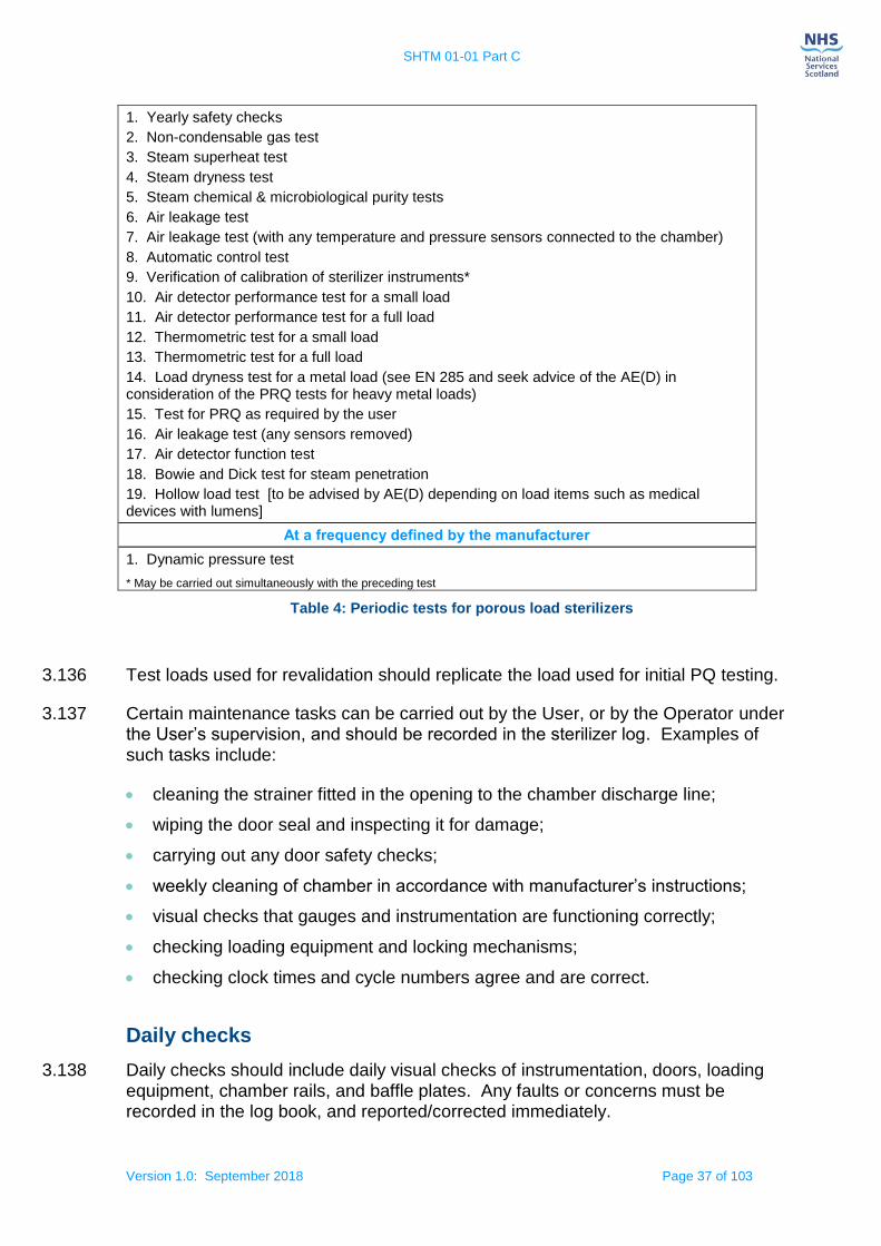
SHTM 01-01 Part C
Version 1.0: September 2018 Page 37 of 103
1. Yearly safety checks
2. Non-condensable gas test
3. Steam superheat test
4. Steam dryness test
5. Steam chemical & microbiological purity tests
6. Air leakage test
7. Air leakage test (with any temperature and pressure sensors connected to the chamber)
8. Automatic control test
9. Verification of calibration of sterilizer instruments*
10. Air detector performance test for a small load
11. Air detector performance test for a full load
12. Thermometric test for a small load
13. Thermometric test for a full load
14. Load dryness test for a metal load (see EN 285 and seek advice of the AE(D) in consideration of the PRQ tests for heavy metal loads)
15. Test for PRQ as required by the user
16. Air leakage test (any sensors removed)
17. Air detector function test
18. Bowie and Dick test for steam penetration
19. Hollow load test [to be advised by AE(D) depending on load items such as medical devices with lumens]
At a frequency defined by the manufacturer
1. Dynamic pressure test
* May be carried out simultaneously with the preceding test
Table 4: Periodic tests for porous load sterilizers
3.136 Test loads used for revalidation should replicate the load used for initial PQ testing.
3.137 Certain maintenance tasks can be carried out by the User, or by the Operator under the User’s supervision, and should be recorded in the sterilizer log. Examples of such tasks include:
cleaning the strainer fitted in the opening to the chamber discharge line;
wiping the door seal and inspecting it for damage;
carrying out any door safety checks;
weekly cleaning of chamber in accordance with manufacturer’s instructions;
visual checks that gauges and instrumentation are functioning correctly;
checking loading equipment and locking mechanisms;
checking clock times and cycle numbers agree and are correct.
Daily checks
3.138 Daily checks should include daily visual checks of instrumentation, doors, loading equipment, chamber rails, and baffle plates. Any faults or concerns must be recorded in the log book, and reported/corrected immediately.
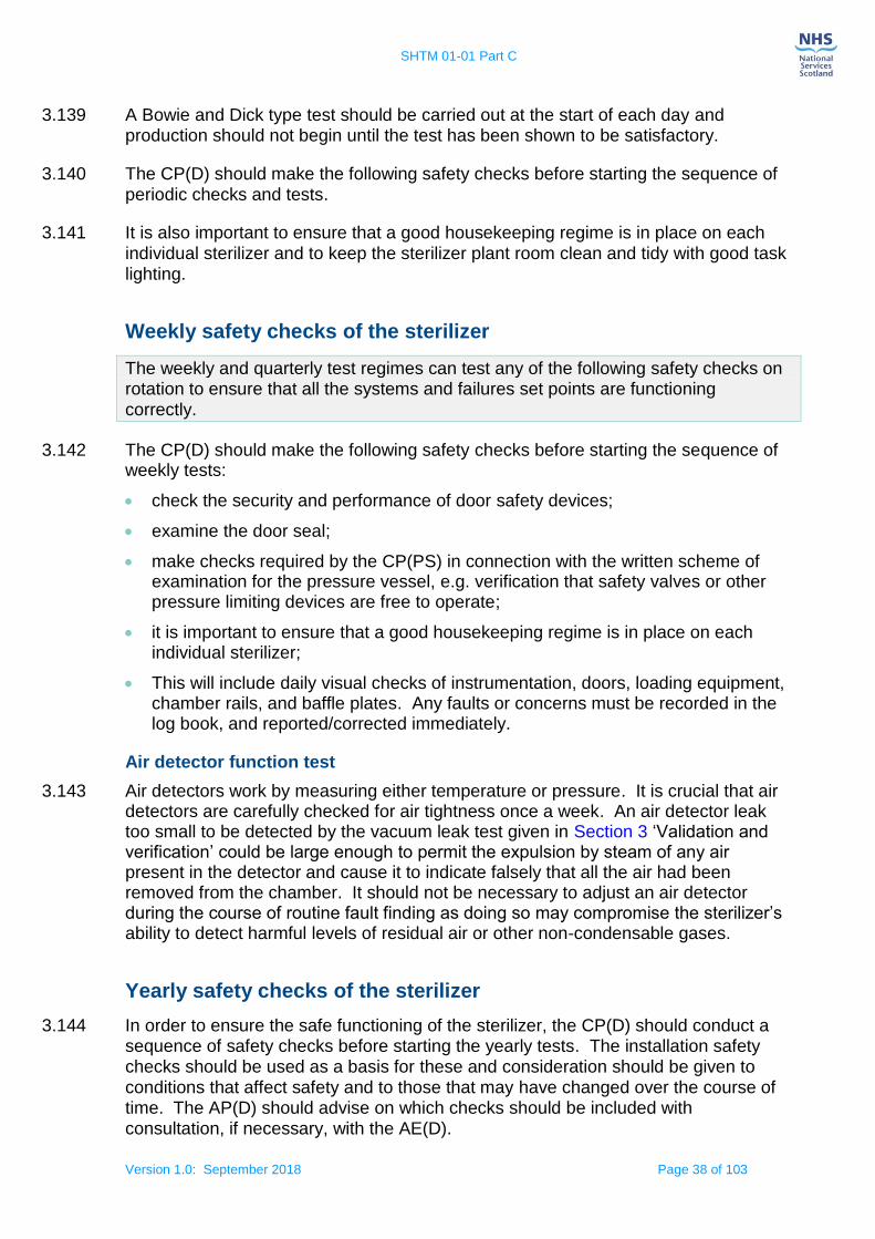
SHTM 01-01 Part C
Version 1.0: September 2018 Page 38 of 103
3.139 A Bowie and Dick type test should be carried out at the start of each day and production should not begin until the test has been shown to be satisfactory.
3.140 The CP(D) should make the following safety checks before starting the sequence of periodic checks and tests.
3.141 It is also important to ensure that a good housekeeping regime is in place on each individual sterilizer and to keep the sterilizer plant room clean and tidy with good task lighting.
Weekly safety checks of the sterilizer
The weekly and quarterly test regimes can test any of the following safety checks on rotation to ensure that all the systems and failures set points are functioning
correctly.
3.142 The CP(D) should make the following safety checks before starting the sequence of weekly tests:
check the security and performance of door safety devices;
examine the door seal;
make checks required by the CP(PS) in connection with the written scheme of examination for the pressure vessel, e.g. verification that safety valves or other pressure limiting devices are free to operate;
it is important to ensure that a good housekeeping regime is in place on each individual sterilizer;
This will include daily visual checks of instrumentation, doors, loading equipment, chamber rails, and baffle plates. Any faults or concerns must be recorded in the log book, and reported/corrected immediately.
Air detector function test
3.143 Air detectors work by measuring either temperature or pressure. It is crucial that air detectors are carefully checked for air tightness once a week. An air detector leak too small to be detected by the vacuum leak test given in Section 3 ‘Validation and verification’ could be large enough to permit the expulsion by steam of any air present in the detector and cause it to indicate falsely that all the air had been removed from the chamber. It should not be necessary to adjust an air detector during the course of routine fault finding as doing so may compromise the sterilizer’s ability to detect harmful levels of residual air or other non-condensable gases.
Yearly safety checks of the sterilizer
3.144 In order to ensure the safe functioning of the sterilizer, the CP(D) should conduct a sequence of safety checks before starting the yearly tests. The installation safety checks should be used as a basis for these and consideration should be given to conditions that affect safety and to those that may have changed over the course of time. The AP(D) should advise on which checks should be included with consultation, if necessary, with the AE(D).

SHTM 01-01 Part C
Version 1.0: September 2018 Page 39 of 103
3.145 The yearly safety checks should include the following services as a minimum:
steam supply;
water supply;
electrical power;
emergency stop activation;
air supply;
air compressor(s);
communication leads/network connection.
Note: All gauges fitted to the sterilizer, both on the front panel and in the plant room should be checked for correct functioning. Check all pipework connections for leaks
and damage and report any faults.

SHTM 01-01 Part C
Version 1.0: September 2018 Page 40 of 103
4. Steam plant
Steam supply
4.1 A continuous supply of saturated steam is required for steam sterilization.
Note: Refer to SHPN 13 Part 1: 2011 Room data sheet for the Plant Room. There is both a General Plant Room and a Sterilizer Plant Room described in the planning note.
4.2 There is a need to specify, for all processes, the quality of steam entering the sterilizer chamber and coming into contact with the load. This section defines a suitable specification for the steam supply.
4.3 The critical variables are the dryness of the steam (expressed as a dryness value), superheat and the level of non-condensable gases (expressed as a fraction by volume). Before a newly installed or replaced sterilizer is handed over to the User, the steam supply should be examined and tested.
4.4 Users should note that where the steam is supplied from the mains, quality can vary greatly during the course of a working day. In many hospitals, steam demand is greatest early in the morning when CDU, kitchens and laundries can start work at the same time. Care should be taken to sample the steam at times throughout a typical working day to gauge the likely range of steam quality. The trend towards 24-hour production may require different sampling patterns.
Operation and maintenance of steam generators
4.5 Users should ensure that operation and maintenance of the steam generator is carried out correctly, both to ensure safety and also to maintain the quality of the steam.
4.6 Steam generators are steam boilers and are subject to the Pressure Systems Safety Regulations 2000 (as amended) and are subject to a written scheme of examination for pressure vessels.
4.7 Guidance on the design, maintenance, testing and operation of steam generators can be found in the Health and Safety Executive’s INDG436 – ‘Safe management of industrial steam and hot water boilers’.
4.8 The advice of the boiler manufacturer about water supply, water treatment, blowing
down and other operational practices should be strictly observed.
Note: Failure to ensure adequate control of water quality and insufficient ‘blow-down’, can resulted in severe corrosion of steam generators leading to the collapse of internal components and potentially putting operators at risk.

SHTM 01-01 Part C
Version 1.0: September 2018 Page 41 of 103
Operation
4.9 A risk assessment should be undertaken to establish the level of supervision required. While it is not acceptable for steam generators to be left continuously unattended, it is not necessary for an operator to be present at all times. The amount and frequency of attention necessary will depend largely on the nature of the water supply, water treatment arrangements and the intensity of use. The operator, who may also be the sterilizer operator, should be adequately trained.
Maintenance of dedicated steam generators
4.10 As there is little condensate return to these steam generators, their feed water is usually almost 100% make-up water. As a result the concentrations of dissolved and suspended solids in the boiler water can quickly build up to very high levels. Such boilers are provided with a “blow down” facility to expel deposits of sludge from the bottom of the boiler. It is essential that an effective blow-down regime is established and adhered to. There are three possibilities:
continuous blow-down – sludge is expelled continuously;
automatic intermittent blow-down – sludge is expelled automatically under the control of a timer or conductivity device;
manual intermittent blow-down – sludge is expelled manually under the control of the operator.
4.11 With manual blow-down there is a risk of affecting the steam quality if this is undertaken at a time when there is a high demand for steam. For this reason manual blow-down should be undertaken at times of light load, preferably when none of the sterilizers are operating. Continuous and automatic blow-down systems should be carefully managed to ensure they do not affect steam quality.
4.12 Guidance on blow-down can be found in the Health and Safety Executive’s PM60 – ‘Steam boiler blow-down systems’.
4.13 Generator vessels constructed from stainless steel will be subject to the same risk of stress-corrosion cracking encountered in stainless steel sterilizer chambers. To minimize the risk the manufacturer’s guidance on feed water quality should be followed.
4.14 A record of all tests and maintenance should be kept in the machine’s plant history file.
4.15 European Standards on medical devices place requirements on the quality of the environment in contact with a medical device (EN ISO 17665 Part 1: 2006) and
specifically give guidance on the chemical quality of steam (EN 285: 2015).
Steam quality – responsibilities
4.16 The AE(D) should be able to advise the User on all aspects of the production and use of steam for sterilization.
4.17 The User should, with advice:
SHTM 01-01 Part C
Version 1.0: September 2018 Page 42 of 103
appreciate the nature of contaminants in steam supply (especially pyrogens), their possible adverse effects and their sources;
understand the requirements of legislation on medical devices as regards sterilization;
be familiar with the current and impending standards on steam sterilization and their implications for steam quality;
understand the difference between process steam, steam as defined in EN 285 and the EN ISO 17665 series, and the appropriate applications of each;
understand the rationale for the steam specification;
understand the engineering principles required for the delivery of steam and how they may be realized for mains steam, dedicated steam generators;
decide whether steam is required for any sterilizer unit and if so, what is the best means of achieving it. Sterilizers employing alternative sterilants such as hydrogen peroxide or ethylene oxide are covered by Part E of SHTM01-01;
appoint a suitable laboratory and liaise with them regarding the analysis of steam condensate and feed water samples;
arrange for the steam supply to be formally validated;
on completion of the validation tests, confirm that the sterilizer is fit for use with the steam supply on the advice from the CP(D) AP(D) and AE(D);
arrange for periodic maintenance of any steam generating and distribution plant from the estates department or the plant directly under the User’s control;
arrange for periodic tests of the steam quality at intervals coinciding with periodic tests on the sterilizer with advice from the AP(D) and AE(D).
4.18 The CP(D) should:
understand and be trained in the operation of the apparatus for taking samples of steam condensate for field analysis, see paragraph 4.158 ‘Sampling’;
be aware of the correct procedures for collecting, preserving and handling samples;
be trained in the measurement of electrical conductivity of water samples using a portable meter;
be trained and aware of the guidance in paragraph 4.5 ‘Operation and maintenance of steam generators’ if maintaining steam generators.
4.19 The Microbiologist (Decontamination) should be able to advise on all microbiological
aspects of steam in conjunction with the AE(D).
Boiler design
4.20 This section discusses the principles by which steam conforming to the steam specifications in Table 6 may be generated. It offers practical guidance on how to achieve steam standards for sterilizers supplied by mains steam systems, dedicated and integral clean steam generators.

SHTM 01-01 Part C
Version 1.0: September 2018 Page 43 of 103
4.21 A full costing analysis should be conducted when the relative merits of different steam supplies are being assessed. The cost of the testing required to demonstrate that a mains steam system can consistently produce steam may amount to a significant fraction of the capital cost of a dedicated steam generator.
4.22 While the boiler may not have been designed with the requirements of steam for sterilizers in mind, it should nonetheless have some means of preventing water being carried over into the steam. The chief precaution against carry-over is good practice in operating the boiler so that foaming and priming do not occur, see paragraph 4.25 ‘How steam is made’. Discussion with boiler-room staff will ascertain the degree to which operating procedures are successful in this regard.
4.23 Steam sampling points on the boiler are desirable and should be installed if they are not already fitted.
4.24 As the operational management of the steam supply may be outside the User’s control, the User should consult with the AP(D) to ensure that the boiler-room staff are aware of the principles of saturated steam for sterilization and that the necessary assurances will be met. The appointment of suitably qualified and trained boiler-room staff is an essential part of this process.
How steam is made
4.25 Steam is generated initially by boiling water then maintaining a continued heat input to convert water into a gas. Boiling occurs at a temperature where evaporated water vapour has sufficient pressure to displace the water immediately below the surface to form bubbles of steam (at lower temperatures evaporation occurs only from the surface). The bursting of bubbles from the surface of the boiling water is accompanied by the ejection of small droplets of water. These droplets contain the same dissolved and suspended solids that are present in the water in the boiler. They are readily entrained in the flow of steam and can carry contaminants to the sterilizer. Even if the water droplets subsequently evaporate, the contaminants will still be present in the form of solid particles.
4.26 Therefore a crucial aspect of boiler design is to ensure the best possible separation and removal of such entrained moisture.
4.27 Priming is a related phenomenon where significant quantities of the boiler water can sporadically be carried over into the steam. This is often as a result of a sudden increase in the demand for steam, which reduces the pressure above the water and effectively lowers the boiling point, so increasing the violence of bubbling. Having a level of water in the boiler that is too high can also lead to priming. Priming should be reduced by standard good operating practice, such as running the boiler at or
near its maximum permissible pressure, using pressure sustaining valves where demand causes a reduction in pressure in the distribution system and not in the boiler.
Summary of requirements for steam
4.28 From the above considerations, the requirements for generating steam can be summarized as follows:

SHTM 01-01 Part C
Version 1.0: September 2018 Page 44 of 103
the feed water should be as free as possible of contaminants, especially those specified for feedwater, see Table 6;
the boiler should be designed to prevent water droplets being carried over into the steam;
the boiler should be operated to prevent foaming and priming;
the boiler and distribution system carrying steam from the boiler to the sterilizer should be resistant to corrosion;
to minimise water carry over, the steam distribution system should be adequately serviced with appropriately designed steam traps;
there should be a regime in place to routinely test the quality of the steam at the point of use;
a risk assessment should determine corrective action in response to particulate test results that exceed specific levels;
any changes to the method of steam generation, feed water chemical dosing and treatment regimes, and design of distribution system need to be clearly documented and monitored;
a planned preventative maintenance regime should be in place to ensure the distribution system and components are functioning correctly.
Public water supply
4.29 While the quality of mains water can differ considerably due to location and water source, it can normally be relied upon to meet the minimum standards set out in The Public Water Supplies (Scotland) Regulations 2014 i.e. the potable water standards. These standards specify more than 50 limits for a wide range of impurities including dissolved minerals, organic compounds and microorganisms.
To assess the need for water treatment, Users should obtain an analysis of the mains water from the supply company over a 12-month period and analyse this data for any periodic trends. Under the Public Water Supplies (Scotland) Regulations 2014 such an analysis should be supplied to customers on request.
Water drawn from the public supply may contain significant concentrations of the salts of the alkaline earth metals (chiefly calcium and magnesium ) giving ‘hard water’ and may also have traces of other contaminants that need to be removed, to ensure water of the desired quality.
4.30 Most water companies use chlorine as a means of microbiological control but by the time the water reaches the point of use the disinfection effect of the chlorine can be
largely lost. Therefore water taken from the mains, and subsequently kept in storage tanks before use, can have significantly higher microbial counts than the original mains water. In the summer months counts greater than 100 cfu/ml are not uncommon. This is of particular concern for sterilization since some 98% of the bacteria found in water supplies are reported to be Gram-negative bacteria, which are the predominant source of pyrogens. Further guidance for the maintenance of water systems within healthcare premises can be found in Scottish Health Technical Memorandum 04-01.

SHTM 01-01 Part C
Version 1.0: September 2018 Page 45 of 103
4.31 There are no requirements for suppliers to measure or control the level of pyrogens in mains water. The level of total dissolved solids (TDS) in the boiler water is another important factor both in the prevention of foaming (see paragraph 4.25 ‘How steam is made’) and for the contaminants that may be present in the entrained water droplets. If steam is to be produced, TDS levels should be below 2000 ppm.
4.32 While some control of TDS concentration can be exercised by appropriate feed water treatments, the boiler usually has a “blowdown” facility to allow accumulated sludge to be expelled from the bottom of the vessel. The water level gauge and TDS sensor element should also be blown down at regular intervals.
4.33 Filming amines, which are often added to feed water to prevent corrosion of condensate return pipes, are toxic and are not acceptable for boilers supplying steam for sterilizers.
4.34 There are no controls; however, on the amounts of atmospheric gases such as Air (the principal non-condensable gas that can impede steam sterilization), carbon dioxide and oxygen are important contributors to corrosion in boiler systems.
Water treatment options
4.35 Although the stated water quality can be relied on most of the time, gross contamination of water supplies may occasionally occur due to engineering works and treatment failures.
Steam generators that are highly efficient at removing water droplets may be able to attain steam standards without the need for further purification of the feed water, but this can only be determined by experiment. Users could consider installing specifically designed feed water purification plant that suits the needs of the site.
Full water treatment consists of three stages:
softening (to remove scale-forming contaminants that may harm the boiler);
purification (to remove other undesirable contaminants);
degassing (to remove corrosive and non-condensable gases).
4.36 The need for softening treatment will depend on the hardness of the local water supply. Where the water is soft it may be possible to achieve the steam requirements without further treatment. In such cases, Users should be aware that the quality of the steam will vary with the quality of the water supply, and that the quality of the steam should be frequently monitored to ensure that the steam specification is maintained.
4.37 In hard-water areas a base-exchange softening plant will normally be required. In this process calcium and magnesium ions are exchanged for sodium ions in a zeolite column (permutite process). The columns are periodically regenerated by flushing with brine (sodium chloride). The flushing should be carried out in accordance with the manufacturer’s instructions to prevent chloride ions being introduced into the softened water.
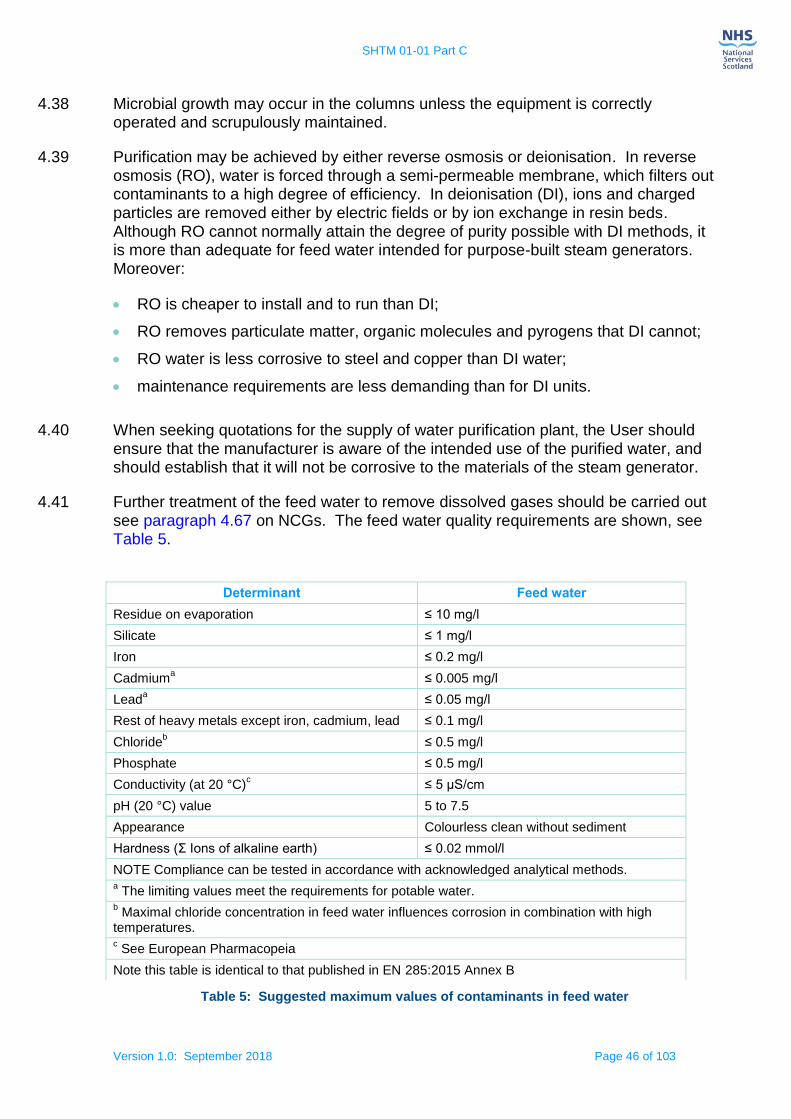
SHTM 01-01 Part C
Version 1.0: September 2018 Page 46 of 103
4.38 Microbial growth may occur in the columns unless the equipment is correctly operated and scrupulously maintained.
4.39 Purification may be achieved by either reverse osmosis or deionisation. In reverse osmosis (RO), water is forced through a semi-permeable membrane, which filters out contaminants to a high degree of efficiency. In deionisation (DI), ions and charged particles are removed either by electric fields or by ion exchange in resin beds. Although RO cannot normally attain the degree of purity possible with DI methods, it is more than adequate for feed water intended for purpose-built steam generators. Moreover:
RO is cheaper to install and to run than DI;
RO removes particulate matter, organic molecules and pyrogens that DI cannot;
RO water is less corrosive to steel and copper than DI water;
maintenance requirements are less demanding than for DI units.
4.40 When seeking quotations for the supply of water purification plant, the User should ensure that the manufacturer is aware of the intended use of the purified water, and should establish that it will not be corrosive to the materials of the steam generator.
4.41 Further treatment of the feed water to remove dissolved gases should be carried out see paragraph 4.67 on NCGs. The feed water quality requirements are shown, see Table 5.
Table 5: Suggested maximum values of contaminants in feed water
Determinant Feed water
Residue on evaporation ≤ 10 mg/l
Silicate ≤ 1 mg/l
Iron ≤ 0.2 mg/l
Cadmiuma ≤ 0.005 mg/l
Leada ≤ 0.05 mg/l
Rest of heavy metals except iron, cadmium, lead ≤ 0.1 mg/l
Chlorideb ≤ 0.5 mg/l
Phosphate ≤ 0.5 mg/l
Conductivity (at 20 °C)c ≤ 5 μS/cm
pH (20 °C) value 5 to 7.5
Appearance Colourless clean without sediment
Hardness (Σ Ions of alkaline earth) ≤ 0.02 mmol/l
NOTE Compliance can be tested in accordance with acknowledged analytical methods. a The limiting values meet the requirements for potable water.
b Maximal chloride concentration in feed water influences corrosion in combination with high
temperatures. c See European Pharmacopeia
Note this table is identical to that published in EN 285:2015 Annex B
SHTM 01-01 Part C
Version 1.0: September 2018 Page 47 of 103
Engineering considerations
4.42 Steam can be obtained from the hospital mains or dedicated steam generators; the requirements for steam quality at point of use are the same in either case, the delivery of high-quality steam depends on careful engineering.
Capacity
4.43 The steam service should be designed to meet the maximum steam demand of the sterilizer(s) for short periods, while keeping the fall in pressure before the final pressure-reducing system to not more than 10%. A single porous-load sterilizer of up to 600 L should use a boiler of at least 50 kW and storage to meet a peak demand of 125 kW for 15 min. The effect on the steam supply of the demands of other sterilizers and equipment connected to the distribution system should be carefully considered. In addition to traditional shell boilers, other options are available such as steam generators and steam/steam generators. Care should be taken when the option of generators is taken over shell boilers as water carry over can be a problem.
Pipework
4.44 Except for vertical rises between floors, steam pipework should be designed so that any condensate flows by gravity in the same direction as the steam. This general principle applies equally to steam mains, branch connections and pipework on the sterilizer itself. Air vents and steam traps should be fitted at each vertical rise. Care should be taken to trap, drain and return any condensate which may be collected in pockets in the pipework. Dead-legs should be avoided.
4.45 The accumulation of condensate in the periods when the sterilizer is not in operation should be avoided, particularly in any part of the pipework and fittings between the take-off from the manifold and the sterilizer chamber. This can be achieved by the correct declination of each portion of pipework and by adequate and correctly sized traps throughout the steam distribution system.
4.46 A suggested layout for the steam service in the Plant Room is shown, see Figure 6. The supply main should terminate in an adequately vented and trapped manifold not less than 150 mm nominal bore that is of adequate length for any future expansion. A vent with a cooling pot should be installed on the manifold upstream of the supply pipes to individual sterilizers. A pressure gauge should be fitted to the manifold. It is good practice to fit a pressure reducing valve (PRV) (and pressure gauges fitted either side to indicate the pressure drop), in the supply line to each sterilizer. The pressure reduction should not exceed 2:1 ratio at each stage of reduction.
4.47 The steam pressure to the manifold should be set within the acceptable range of supply pressure to the sterilizer as specified by the manufacturer. The line velocities should be kept below 25 metres/sec, to allow steam traps to remove entrained moisture effectively and to prevent condensate being drawn out of the condense lines and pockets.
4.48 If the sterilizer manufacturer has not already fitted them, an appropriate and correctly installed separator and steam trap should be fitted upstream of the sterilizer reducing valve. Advice should be sought from the AE(D) and CP(PS).

SHTM 01-01 Part C
Version 1.0: September 2018 Page 48 of 103
4.49 Three suitable test connections should be provided on the supply pipe to each sterilizer to permit the attachment of a needle valve, a pitot tube and a temperature sensor as shown in Figure 6. Safe access should be provided for the CP(D) to carry out steam quality tests including the provision of convenient cooling water and electrical supplies for test purposes.
4.50 Careful attention should be paid to the location of all pressure relief valves to ensure that the sterilizer is properly protected. Relief valves and their discharge pipes should be large enough to prevent the pressure in the supply pipe from the manifold rising to more than 10% above the design pressure for the manifold.
4.51 The discharge pipe should terminate outside the building in a safe, visible position not affected by frost. Any rising discharge pipe should be fitted with a drain at the lowest point to prevent the accumulation of condensate. A tell-tale pipe of narrow bore should be connected to the drain point and should terminate inside the Plant Room for clear indication of condensate and pressure/valve problems.
Figure 6 Layout of Plant Room steam service (steam header)

SHTM 01-01 Part C
Version 1.0: September 2018 Page 49 of 103
Steam impact on Sterilizer construction materials
4.52 To meet the steam purity standard for sterilizers, sterilizer parts in contact with steam entering the chamber should be constructed from low-carbon or stabilized stainless steel. Check each manufacturer’s specifications at the procurement stage.
Dryness
4.53 Saturated steam is required for sterilization so that sufficient energy is transferred to the load upon condensation in order to achieve the required lethality. The dryness of the steam is therefore of vital importance; too little moisture carried in suspension may allow the steam to become superheated during expansion into the chamber and thus impair sterilization, while excess moisture may deliver insufficient energy to the surface of the load to be sterilized and additionally may cause damp or wet loads and uneven temperature distribution.
4.54 Steam dryness is traditionally characterized by a ‘dryness fraction’, but this is not appropriate for sterilizers because the method of measurement is difficult and requires a constant flow of steam. The low-volume sampling technique described in the steam dryness test (see paragraph 4.249 ‘Steam dryness test’) cannot be regarded as measuring a true dryness fraction because the sample is taken from the centre of the steam supply pipe and condensate flowing along the pipe wall is not collected.
4.55 Consequently the term “dryness value” is used, where “1.0” represents dry, saturated steam. This method is used to determine whether performance problems could occur during testing and routine production. It is suitable for sterilizer installations because control valves and pipe services fitted to the sterilizer considerably reduce the amount of condensate entering the sterilizer chamber such that the sample has a similar amount of free condensate to the steam in the chamber.
4.56 European Standards require that sterilizers be designed to operate with steam having a dryness value of not less than 0.9 when measured in accordance with the steam dryness test described in paragraph 4.249 ‘Steam dryness test’. For metal loads, the dryness value should not be less than 0.95. In practice, problems are unlikely to occur if the pressure reduction through the final pressure reducing system is of the order of two to one.
4.57 Deviations from this specification are likely to cause the following problems:
wet loads, resulting from too low a dryness value;
superheating, resulting from either too high a dryness value before the pressure-reducing stage, or excessive pressure reduction through a valve or other restriction in the pipework (superheating may be severe if both conditions are present simultaneously);
difficulties with operation of the pressure reducing system, resulting from a low pressure reduction ratio, water hammer, water logging, dirt and water carry-over.
Excessive moisture
4.58 Possible causes of excessive moisture, where droplets of water are present in the steam and at the same temperature as that of the steam, are:

SHTM 01-01 Part C
Version 1.0: September 2018 Page 50 of 103
steam pipes or manifolds may be incorrectly sloped and drained; insufficient trapping;
incorrect traps fitted to the system, or malfunctioning traps;
the sterilizer may be supplied from an inadequately drained and vented dead-leg rather than a live steam main and flow;
the pipework between the boiler and the sterilizer may be insufficiently insulated, causing excessive condensation of the supply steam;
the steam manifold may not be adequately served with appropriate steam traps and air vents to ensure optimum conditions at the sterilizer.
4.59 If wet steam continues to be a problem, “priming” may be occurring in the boiler, causing water droplets to be delivered in the steam. Modern, compact, and high-rated boilers and steam generators are particularly sensitive to the quality of feed-
water treatment and are much more likely to prime than boilers of traditional design. Priming or foaming (which results in carry over of the boiler water) can be caused by any of the following:
incorrect feed-water treatment;
boiler water level being set too high;
forcing a boiler which needs internal cleaning;
violent boiling under fluctuating load conditions;
a high level (typically 2000 ppm) of total dissolved solids (TDS).
4.60 The relationship between water injection timing and steam generation should also be checked in order to reduce water slugging of the system. Generators are designed for the water to be injected before the flame to protect the coils, hence if too much time lapse is present, liquid water will carry over into the system.
Superheating
4.61 Superheated steam is an unsuitable medium for moist heat sterilization and can cause failure to sterilize, scorching of textiles and paper, and rapid deterioration of rubber. Superheated steam behaves as a dry gas and can have a lower microbicidal effectiveness in comparison with saturated steam. Superheat conditions within the load and chamber may result from adiabatic expansion, exothermic reaction or both.
4.62 European Standards require that the superheat in free steam at atmospheric pressure should not exceed 25ºC when measured by the superheat test.
4.63 Superheated steam is uncommon and can be difficult to identify. A failed process indicator is one sign while charring of wrapping materials is another. Thermometric tests may also provide evidence of superheated steam. One possible cause of superheated steam is an excessive reduction in pressure through a throttling device, such as a pressure reducing system or a partially closed main steam valve. In this case superheating arises from adiabatic expansion, and is usually the result of an excessive reduction in pressure through a throttling device or torturous pipework and joints, a pressure reducing system or a partially closed main steam valve. It is

SHTM 01-01 Part C
Version 1.0: September 2018 Page 51 of 103
unlikely to be of significance in the circumstances normally encountered in CDU steam distribution systems.
4.64 Superheat can also occur if the steam is admitted into the chamber with excessive velocity. This problem is usually detected and overcome during commissioning by fitting a throttling device in or over the steam inlet port with some modifications to the baffle plate assembly. Superheating may also arise if the pressure is unusually high before the throttling device. This superheat can sometimes be avoided by measures that reduce the dryness value of the steam at the inlet to the sterilizer pressure reducing system. The reduced pressure ratio will minimize the effect of the expansion through it.
4.65 Another possibility is superheating from exothermic reaction, which can occur as a result of rehydration of exceptionally dry (hygroscopic) material. In these circumstances, the superheating can persist for the entire holding time with consequential risk of a failure to sterilize. It is usually associated with certain textiles, particularly those incorporating cellulosic materials (such as cotton or paper), which have become excessively dry before sterilization. It can occur during periods of very cold, dry weather especially where the materials to be sterilized are kept in rooms that are heated and mechanically ventilated without humidification.
4.66 This is one reason for airing the standard test pack between successive tests.
Non-Condensable Gases
4.67 Non-Condensable Gases (NCGs) are defined as gases that cannot be liquefied by compression under the range of conditions of temperature and pressure used during the sterilization process. Low levels of NCGs contained in steam supplied to sterilizers can markedly affect the performance of the sterilizer and the efficacy of the process, can cause chamber overheat and can lead to inconsistencies in the performance of air detectors and failure of the Bowie and Dick test, see Section 5 ‘Operation of porous-load sterilizers’. The major NCGs are air and carbon dioxide.
4.68 European Standards require that sterilizers be designed to operate with steam having a fraction of NCGs not exceeding 3.5% by volume of gases to steam that has been condensed when measured by the method described, see paragraph 4.224 ‘Non-condensable gas test’.
4.69 The main source of NCGs in the steam supply is the boiler feed-water, and the level will be greatly influenced by the water treatment employed. In some cases an investigation by a water treatment specialist will be necessary. The investigation should cover analysis of the water, and the venting and the blow-down regime required to protect the boiler against corrosion while minimizing the entrainment of
NCGs in the steam supply.
4.70 If anti-foaming agents and oxygen-scavenging agents (such as sodium sulphite) are used, checks should be made to ensure that the dosages are accurate.
4.71 Water-softening treatments can be employed to prevent the formation of limescale.
4.72 A base-exchange softener will reduce limescale but will also produce bicarbonate ions, which will break down into carbon dioxide in the boiler and give rise to an
SHTM 01-01 Part C
Version 1.0: September 2018 Page 52 of 103
increase in NCG levels. Therefore in order to drive off dissolved air, carbon dioxide and other NCGs in the boiler, feed-water should be degassed before use.
4.73 This is usually achieved by pre-heating the water in a “hot well” maintained at temperatures of 80–90ºC (at atmospheric pressure) to drive dissolved gases out of solution. For the degassing to be effective, the temperature of the feed-water should not fall below 80ºC at any time. This will also break down bicarbonate ions, driving off further carbon dioxide.
4.74 The hot well is often provided by the manufacturer of the steam generator as an integral part of the unit.
4.75 The following measures should be adopted:
pipework returning condensate to the hot well should be well lagged to keep the condensate hot;
the amount of cold make-up water in the hot well should at no time exceed 15% (the rest being returned condensate), since new water will both lower the temperature and introduce further NCGs;
the water in the hot well should be kept well mixed.
4.76 This may be achieved by locating the feed-water inlet on the opposite side of the tank from the outlet and by arranging for the feedwater to be “sparged” from the inlet through a number of small openings.
4.77 In very hard water areas the level of NCGs may still be high despite these measures. Where this is the case, the feed-water should undergo de-alkalization treatment and the high temperatures in the hot well should be maintained. Treatment with filming amines is not permitted for sterilization applications.
4.78 Users should note that, even with a well-designed system, the level of NCGs can be affected by competing demands on the steam service; for example, where a central steam boiler supplies both a sterilizer unit and other departments (such as laundry equipment) through the same distribution system the level of NCGs in the steam at the sterilizer may vary depending on total demand on the boiler and distribution system.
4.79 Some other causes of the presence of NCGs in the steam are as follows:
the boiler may be priming, see paragraph ‘Dryness section 4.53’;
air may be being drawn into the system either through the boiler’s feed-pump glands or through a leak in the steam pipework between the boiler and the sterilizer;
steam pipework may be inadequately vented;
hot well temperature too low;
insufficient trapping in system or malfunctioning traps.
Where NCGs are found in the sterilizer chamber during a production cycle;
there may be an air leak into the chamber;

SHTM 01-01 Part C
Version 1.0: September 2018 Page 53 of 103
packaging materials, for example, certain boxes, inks, adhesives, labels or trays may be liberating gases.
4.80 High concentrations of impurities in the boiler water also promote carry-over. They reduce the surface tension and so increase the agitation of the water surface. They can also cause the formation of foam above the water surface leading to severe carry-over. Slugs of water are intermittently discharged from the boiler along with the steam, severely prejudicing the quality of the steam.
Steam quality requirements
4.81 Recent years have seen a growing awareness of the need to monitor, test, report and improve the quality of steam used for sterilization, due in part to regulatory requirements for medical devices but also by increasing concern about the potential harmful effects of even minute quantities of contaminants on patients. EN ISO 17665
Part 1 requires that impurities in any medium in contact with the medical device be known and limits of acceptability identified.
4.82 The requirements, see Table 6 should be met when measuring the quality of steam. The AE(D) can advise on the number of tests required and the actual test point depending on the steam distribution system, header design and numbers of sterilizers in the unit.
4.83 Pyrogens are of particular concern because, unlike other contaminants, there are no controls on the levels of pyrogens in public water supplies from which steam is generated. They are extremely heat stable and are only destroyed after prolonged exposure to high and are not inactivated by any of the standard sterilization processes employed for medical devices. Therefore control of pyrogens in steam for sterilization should be a priority.
4.84 Bacterial endotoxins are derived predominantly from Gram-negative bacteria, which give rise to high temperatures and fever-like reactions when injected into man and other mammals. Bacterial endotoxins are by far the most common pyrogenic compounds and are also of the greatest significance in sterile product manufacture.
4.85 Bacterial endotoxins are extremely heat-stable and are only destroyed after prolonged exposure to high temperatures (3 hours at 180°C or 30 min at 250°C). They are not destroyed by any of the sterilization processes commonly employed for medical devices.
4.86 Many sterile medical devices are intended for use during clinical procedures where the dermis may have been breached allowing the sterile product to come into direct contact with the vascular system and if endotoxins are present for example where medical devices with a large metal mass are processed steam can condense on the surface depositing bacterial endotoxins that can cause a pyrogenic reaction.
4.87 It is not always recognised, that a requirement exists for medical devices to be free from pyrogens or that the steam sterilization process can be a source of pyrogen contamination.
4.88 Two factors are of greatest importance in ensuring that the steam supply is pyrogen-free:

SHTM 01-01 Part C
Version 1.0: September 2018 Page 54 of 103
the quality of the feed water to the steam raising plant. High levels of pyrogens or high bacterial counts in the feed water can result in even limited carry-over of water droplets in the steam making a significant contribution to the pyrogen level;
the performance of the steam raising plant, in particular that its design, construction and mode of operation ensure that there is the minimum carry-over of entrained droplets of water.
4.89 For practical purposes steam for use in sterilizers may be regarded as pyrogen-free when a condensed, representative, sample meets the European Pharmacopoeial standard for Water for Injections, that is, less than 0.25 EU mL–1.
Table 6: maximum values of contaminants in steam condensate collected according to the methods described in EN 285: 2015
Steam distribution system
4.90 The distribution system also influences the quality of steam delivered to the sterilizer. The design of distribution systems suitable for the delivery of dry, saturated steam is
Physical qualities:
Dryness ≥0.95
NCG ≤3.5%
Superheat ≤25C
Particulate qualities:
Silicate ≤0.1 mg/L (corrosion)
Heavy metals ≤0.1 mg/L (corrosion and load)
Cadmium ≤0.005 mg/L (corrosion)
Lead ≤0.05 mg/L (corrosion)
Chloride ≤0.1 mg/L (corrosion), ≤0.5 mg/L (load)
Phosphate ≤0.1 mg/L (corrosion and load)
Conductivity (at 25°C) ≤3 μS/cm (corrosion), ≤35 μS/cm (load)
pH 5–7 (corrosion)
Hardness ≤0.02 mmol/L (corrosion)
Appearance clear, colourless, no sediment (corrosion), clear and colourless (load)
Bacterial endotoxins ≤0.25 EU/mL (load)
Ammonium ≤0.2 mg/L (load)
Nitrate ≤0.2 mg/L (load)
Sulphate Ra (load)
Oxidisable Sub Ra (load)
Evap Residue ≤30 mg/L (load)
Calcium & magnesium Ra (load)
NOTE: This table is a combination of tables A1 (re: corrosion) and A2 (re: load) in CEN ISO/TS 17665 Part 2: 2009. Compliance with this Table addresses the issues of equipment corrosion and load contamination.
NOTE: Ra signifies methods and reagents specified in the European Pharmacopoeia

SHTM 01-01 Part C
Version 1.0: September 2018 Page 55 of 103
considered in paragraph 4.1 ‘Steam supply’.
4.91 A purpose-built distribution system for steam for sterilization would normally be constructed of stainless steel. However, when a large conventional installation has been in use for a number of months, a hard protective layer of oxide (magnetite (Fe3O4)) may have formed on the inside of the steam pipes.
4.92 Providing the steam condensate is neutral or alkaline, this coat will remain intact and permit the use of the pipework for the distribution of steam. Acidic condensate in the presence of moist air, however, can break down the layer, leading to corrosion, which may then be shed as contaminating particles.
4.93 This substance forms fine particulates that are not readily removed by the strainers normally installed in steam services. This can occasionally be seen as black or reddish-brown discoloration of packaging material
4.94 The hydrogen liberated by the formation of magnetite (400 ml for each gram of iron) can also contribute appreciably to the amount of non-condensable gases in the steam delivered to the sterilizer, especially in new installations with long pipe runs.
4.95 It is important that the distribution system is free of dead-legs and other places where condensate may become trapped otherwise contamination as rust is likely to arise at points where water can collect, such as dead-legs, gauges and poorly maintained traps. This can be shed into the steam as rust particles. During periods when the steam supply is off, such accumulation of water may also become a focus of microbial growth and the formation of biofilms, which periodically generate high levels of contamination as they slough off.
4.96 Other key points for a distribution system suitable for steam include:
correctly sized automatic air vents throughout the pipework distribution system to minimise the amount of air and other non-condensable gases delivered to the sterilizer;
properly sized and selected steam traps to remove condensate and air (if designed to do so);
steam pipeline velocities kept below 25 m s–1 to allow steam traps to remove entrained moisture effectively and to prevent condensate being drawn out of them;
steam separators near the steam take-off on boiler plant prone to generating wet steam;
strainers to protect control valves, steam traps etc.
Assurance of the steam quality
4.97 Where a mains steam supply is found to be capable of meeting the steam specification, Users should assess whether the steam quality can be maintained under all operating conditions. There are several points to consider:
programmed testing of the steam at the sterilizer will provide assurance that the steam specification is consistently met;

SHTM 01-01 Part C
Version 1.0: September 2018 Page 56 of 103
competing demands on the steam service from other units in the hospital can degrade the steam quality at the sterilizer;
steam quality is apt to vary through the year as the boiler room responds to changing seasonal demands;
an otherwise effective steam supply can quickly deteriorate if appropriate periodic maintenance is not carried out;
arrangements should be made for the User to be warned of imminent engineering modifications, maintenance and changes in steam generation, distribution and operating practice. If changes are likely to be made without the User’s knowledge, the supply cannot be considered a reliable source of steam.
Steam from the mains steam supply
4.98 Experienced and monitored tests have shown that steam of suitable quality can be
obtained from well designed, constructed and operated conventional boilers and distribution systems of the type found in most hospitals. If steam from this source is chosen, it is essential to demonstrate compliance and identify maintenance and boiler treatment regimes necessary for reproducibility.
4.99 Where a central supply does not deliver steam of acceptable standard, it is possible that the quality may be sufficiently improved by changes in operating practice and relatively minor engineering modifications. However it is unlikely to be economical to embark on extensive remedial works such as the introduction of new feed water treatment plant or the replacement of distribution pipework. It may be more cost effective to install a dedicated steam generator solely to supply sterilizers, see next paragraph.
Steam from a dedicated generator
4.100 A dedicated steam generator, whether supplying one or several sterilizers, should be used where steam cannot be reliably obtained from the mains supply or for new installations if cost effective to do so. Since the bulk of the condensate from sterilizers is discharged to waste and not returned to the boiler, such generators may have to run on practically 100% make-up feedwater.
4.101 A dedicated system should therefore:
minimise the amount of non-condensable gases and other contaminants in the boiler feed water;
prevent liquid water leaving the boiler and being delivered in the steam;
prevent microbial growth in any storage tank or pipework;
be constructed from materials resistant to corrosion and particle shedding, such as low carbon stainless steel (type 316L).
4.102 The capacity of the generator should be sufficient to meet both maximum and minimum demands while still maintaining the requirements for dryness and non-condensable gases specified in paragraph 4.224 ‘Non-condensable gas test’.
4.103 Steam sampling points should be fitted between dedicated generators and the sterilizer entry point so that steam quality tests can be performed.
SHTM 01-01 Part C
Version 1.0: September 2018 Page 57 of 103
Moisture separation
4.104 A dedicated steam generator should allow the entrained water droplets to be separated from the steam before it is delivered to the sterilizer. The baffles used in some conventional boilers are not normally adequate for this purpose. Satisfactory results have been obtained using cyclonic separators, which essentially spin-dry the steam by causing it to rotate at high speeds. Experience has also shown that the installation of a large plate type separator fitted in the main steam line can safely remove water carryover from the distribution system prior to the header protecting the load.
4.105 Adequate moisture removal should be maintained over the entire range of steam demand, typically up to 200 kg h–1 for each sterilizer.
Heating of steam generators
4.106 A single 600 L porous-load sterilizer requires a steam generator capable of converting energy at a rate of up to 50 kW. A group of sterilizers will require a proportionately higher heating power. Steam demand for peak and average flows should be obtained from the sterilizer manufacturers, and peak demands utilized for sizing the steam generators and distribution system.
4.107 Where existing sterilizers are supplied from a central boiler, the ideal solution is to install a generator heated by mains steam. The steam generator is then effectively a steam-to-steam calorifier in which the mains steam is used only to heat the feed water and does not come into contact with the steam for the sterilizer.
Primary steam requirements for this type of calorifier will normally be 300 kg h–1 for each sterilizer at a minimum pressure of 10 bar and operating on 100% condensate return. Where mains steam is not available, a small packaged boiler may be a convenient source of steam for heating, but should not itself be regarded as a source of steam.
4.108 Generators may be heated by electricity, but size for size, an electrically heated generator cannot match a steam-to-steam generator for heating power. The pressure in the boiler cannot be maintained at a high enough level to ensure adequate removal of droplets by the cyclonic method described above. Gas-fired heating is not recommended for stainless steel boilers.
Materials of the steam generator and associated pipework
4.109 The boiler and other parts of the generator that come into contact with feed water or steam should be constructed of corrosion-resistant stainless steel (such as low-carbon 316L grade).
4.110 Pipework connecting the steam generator to the sterilizer should be also constructed in stainless steel. Since the generator can be sited close to the sterilizer, it is a false economy to re-use existing sections of the steam supply system.
4.111 While existing sterilizers should not be harmed by a carefully-designed steam system, steam-contact with surfaces of iron, mild steel or copper in new machines should be avoided. In most cases this will require contact surfaces to be fabricated in stainless steel as specified in EN 285.

SHTM 01-01 Part C
Version 1.0: September 2018 Page 58 of 103
Steam generator feed water treatment
4.112 As there is no return of chamber condensate from the sterilizer, the quality of feed water is crucial to the performance of a steam generator/boiler. It is especially critical for those generators that operate on a straight-through principle and have no reservoir of water within the boiler. Refer to water quality section for other requirements.
Contamination in steam supplies
4.113 This section discusses the adverse effects that impurities in the steam supply can have on patients, equipment and the sterilizer. It identifies the products most likely to be susceptible to contamination and reviews the means by which various contaminants find their way into steam for sterilization. The designer of a robust steam supply should ensure that all the above requirements are met and the boiler system is designed to provide minimal carry-over of entrained water droplets and is able to maintain a low level of contaminants in the steam even where the quality of feedwater is poor.
4.114 However, if the feed water is of low quality, even small deviations from optimum operating conditions of the steam supply may result in large amounts of contaminants being carried over and delivered to the sterilizer.
4.115 There are a number of specific contaminants known to have adverse effects and whose presence in steam is therefore undesirable.
The first step in assessing whether steam can be supplied from the mains is to examine the design and operation of the boiler plant.
4.116 An important consideration is the proportion of boiler feed water that is fresh “make-up” water rather than steam condensate returned from the distribution system. While the nature of the feed water treatment is also of importance, the requirements for steam for sterilization are unlikely to be achieved if the proportion of makeup feed water exceeds 15%. In large facilities, where steam is supplied centrally, only a small fraction of the steam demand is due to sterilizers (which discharge most of their condensate to waste) and therefore the bulk of the condensate is returned to the boiler. This can make it more feasible to control the level of contaminants in the boiler.
4.117 Further contaminants can be introduced either deliberately or inadvertently as a result of treatments applied to mains water before it can be used as boiler feedwater.
4.118 Base-exchange water softeners remove calcium and magnesium ions from the water
and replace them with sodium ions. (see paragraph 4.100 ‘Steam from a dedicated generator’). Sodium levels will therefore be raised in mains water softened by this method. The use of brine to regenerate the ion exchange beds can temporarily raise the level of chloride.
4.119 Bacterial growth can occur in water softening, deionisation or reverse osmosis plant unless the manufacturer’s operating and maintenance procedures are strictly adhered to.

SHTM 01-01 Part C
Version 1.0: September 2018 Page 59 of 103
4.120 While bacteria will not survive the steam generating process, the pyrogens they produce could be delivered to the sterilizer.
4.121 Any chemicals added to the boiler water can be carried into the steam as contaminants either in droplets of water entrained in the steam during the evaporative process or as volatile components present as gases. Corrosion inhibitors and other chemicals, used to prevent corrosion in steam systems and boilers, should only be used in concentrations that are proven not to pose a risk to patients via medical devices they are in contact with, or not to have an adverse effect on packaged medical devices. Concentrations of such chemicals should be carefully monitored to ensure that safe limits are not exceeded.
Note: Any significant alterations to the chemical dosing regime used to treat the feed-water supply for the sterilizer steam supplies should be clearly documented with quantities, dates and chemicals and a further testing of the steam quality may be
required. Advice should be sought form the AE(D).
Adverse effects on patients
4.122 Several contaminants are known to have adverse effects on patients, such as:
metals: Many of these are toxic (some are cumulative poisons) and therefore their presence is undesirable. Metals of particular concern include cadmium, lead, mercury and other heavy metals;
microorganisms: This includes all pathogens and all Gram-negative bacteria (which are sources of pyrogens which can cause severe reactions when administered intravenously);
particulate material: Solid particles can lead to a number of adverse effects if introduced into the body.
Contaminants delivered to the sterilizer in steam can arise from a number of sources:
contaminants present in the public water supply from which the steam is generated;
contaminants arising from treatment of the boiler feedwater;
possible contaminants arising in the distribution system carrying steam to the sterilizer.
Adverse effects on materials
4.123 Contaminants in steam can have a damaging effect on the materials of the load and the sterilizer.
4.124 The reaction of steam with surfaces is affected by its pH. In general, steam of a low pH (acidic) will react with and dissolve metals. A pH of approximately 7 (neutral) is ideal and deviation towards alkaline (for example to pH 8) is acceptable. Reactive contaminants in the steam (e.g. chlorine) can cause corrosion or otherwise impair the longevity or function of the product. Reactions can occur when contaminants interact with the product directly or indirectly (by interacting with materials that will subsequently come into contact with the product).

SHTM 01-01 Part C
Version 1.0: September 2018 Page 60 of 103
4.125 The steam also comes into direct contact with the internal surfaces of the sterilizer pressure vessel and associated equipment and instrumentation. Contaminants within the steam can react with the materials of construction and cause corrosion of the equipment or otherwise impair its longevity or function.
4.126 Contaminants of concern include the following:
Alkaline earth metals cause “hardness” which can lead to build-up of limescale in the sterilizer chamber and in pipework. Most problems are caused by calcium and magnesium and, to a lesser extent, strontium;
Iron, whether in metallic or ionic form, is corrosive to stainless steel;
Chlorides in the presence of oxygen lead to pitting corrosion and (to a lesser extent) crevice corrosion in stainless steel. The effects can be controlled by limiting the amount of oxygen in the feed water;
Phosphates and silicates act to concentrate chloride ions and so promote their corrosive effects. Silicates may also cause colour changes in some medical devices although this is often only cosmetic.
4.127 The materials used in the construction of load items of medical devices and of the sterilizer itself will determine which contaminants are of greatest importance in each case. EN 285, the European Standard for sterilizers used to process medical devices, offers guidance on materials for construction suitable for all steam sterilizers.
4.128 Steam sampling systems should be constructed of materials that will not react with, and hence contaminate, the sample being collected.
Products vulnerable to steam-borne contamination
4.129 Any product can become contaminated if it comes into contact with the steam supplied to sterilizers. Contaminants in the steam are deposited on the product as the steam condenses during the heating-up stage. The amount of steam condensing, and hence the amount of contamination deposited, is proportional to the heat capacity of the load items of medical devices, which in turn is proportional to its mass and the specific heat capacity of the material from which they are made. A massive metal medical device will therefore receive much more contamination than a light plastic medical device of similar size and shape heated to the same temperature.
4.130 The amount of contamination remaining at the end of the cycle will depend on how much condensate is retained at the surface of the product. Where condensate can drain freely from the medical devices, a small fraction of the deposited contaminants will be held in a thin film of water and the total amount remaining when the film is evaporated will be proportional to the exposed surface area. Where condensate is trapped in cavities or held in the packaging close to the surface, the amount of contamination retained will be proportionally greater.
4.131 Packaging materials for steam processes have a filtering effect that protects against contamination to some extent. Particulate matter is normally trapped on the outer wrapping (giving rise to discoloured packs) but smaller particles and all molecules will

SHTM 01-01 Part C
Version 1.0: September 2018 Page 61 of 103
pass through with the steam and be transferred to the product as the steam condenses on it.
4.132 Whether such contamination has any adverse effect is dependent on the nature and intended use of the medical device and the risk of transfer of contaminants to the patient, examples may include;
dressings and swabs;
surgical instruments
surgical implants.
4.133 Various items of equipment used in the manufacture of medical devices should be sterilized before use. It is important that during sterilization these items of equipment are not tainted with contaminants that could be subsequently transferred to the medical devices being manufactured.
Steam supply testing for compliance
4.134 This section discusses the testing regimes necessary for the initial validation of a steam supply for sterilization and subsequent periodic testing. Methods for taking steam samples are given in this section and their analysis is discussed in paragraph 4.216 ‘Analysis of samples’.
Where to take samples
4.135 To ensure a thorough quality assessment of the steam supply, water and steam samples should be taken throughout the steam generating and distribution system, from the incoming water to steam at the point of use or sterilizer supply. Such an extensive testing regime used throughout the whole generation and distribution system is rarely required in practice. Examples of points at which samples may be taken include:
mains water, which after suitable treatment will be used as feed water to the boiler;
treated water, which may include one or more distinct treatment stages. Samples should be taken from the inlet and outlet pipes as close as possible to the treatment plant. To monitor the various stages of water treatment, samples should be taken after each stage;
feed water, the water admitted to the boiler from the hot well without any dosing treatments admitted simultaneously or separately to the boiler;
boiler water, the water in the boiler prior to blow-down;
boiler steam, the steam leaving the boiler;
steam for use in the sterilizer, the steam delivered to the sterilizer, sampled at the steam service pipe.
4.136 Testing of the total system can be costly and may only be required where major problems are experienced.
SHTM 01-01 Part C
Version 1.0: September 2018 Page 62 of 103
4.137 The sampling points should be chosen so that the samples obtained will allow the identification and quantification of any significant changes in contamination levels at each stage in the process; e.g. sampling before and after a base-exchange water softener may reveal an increase in bacterial endotoxin levels from a contaminated ion exchange column. A full set of sampling points at strategic locations will allow such problems to be investigated with a minimum of disruption, even though most of them will rarely be used in routine operation.
4.138 The design and construction of the system will determine how many sampling points would be of value. For a mains system supplying a large hospital all the above points may be desirable. For a sterilizer with an adjacent, dedicated steam generator supplied from a simple treatment plant, fewer would be needed.
Validation and periodic testing of the steam supply
4.139 Validation tests should normally be carried out on the following occasions:
on initial validation of the steam-raising and distribution plant;
on initial validation of the sterilizers served by the steam plant;
on yearly testing or revalidation of the sterilizers;
when there is operational evidence that the steam quality may have deteriorated;
after any significant modification of the steam plant or its operation.
4.140 Periodic testing of the steam supply should be carried out quarterly to coincide with the quarterly tests scheduled for the sterilizer. Periodic testing of the feed water is not necessary. The test should consist of a conductivity measurement of a field sample, see paragraph 4.175 Field tests for steam – conductivity and pH measurements, and the conductivity value should remain below the limit established during validation. A failure of the periodic test (i.e. the conductivity measurement is above the validation level) requires further investigation, normally by a full laboratory analysis of both feed water and steam.
4.141 Revalidation should be carried out once a year, to coincide with the yearly testing of the sterilizer.
4.142 Additional tests may be required if problems are experienced with steam quality/ contaminants. The advice of the AE(D) should be sought as to frequency of testing required in that case.
Periodic conductivity tests of the steam should be carried out during quarterly testing of the sterilizers.
4.143 As a minimum, samples for validation should include the feed water and the steam for use in the sterilizer. Testing the steam without testing the water from which it is raised can lead to a false sense of security.
4.144 For example, high levels of pyrogens in the feed water will not necessarily produce contamination in the steam when the boiler is operating under loads that do not induce carry-over or priming. But during normal operation this could occur and

SHTM 01-01 Part C
Version 1.0: September 2018 Page 63 of 103
contamination in the feed water would require urgent investigation and remedial action.
4.145 Once a steam supply has been validated, periodic testing of steam quality will be necessary. Quarterly testing of electrical conductivity is recommended, see paragraph 4.175, but the frequency will depend upon the particular application and the consistency of control established from historical data. Other tests may be necessary if one or more of the possible contaminants is critical for the process or product.
4.146 The AP(D) and CP(D) should first establish when the steam generator will be subject to the highest and lowest demand. Depending on the design of the steam plant, it is possible for either to constitute the worst-case conditions for carry-over of moisture. For example, a large plant designed to supply several sterilizers and relying on a cyclonic separator for removal of entrained water droplets may be inefficient at the lower velocities generated by a single sterilizer on light load.
4.147 The highest demand on the boiler usually occurs when all sterilizers are operating simultaneously. However, the period of peak demand (steam admission into the chamber) is brief, and it is difficult to synchronize the operating cycles so that the peaks coincide for long enough to allow a sample to be taken. The peak demand of any sterilizer is usually at the steam admittance point at the end of the deepest pulse stage.
4.148 An alternative method is to vent steam from the relief valve on the plant room manifold. Users should first ensure that the steam will be discharged to a safe position outside the building. The relief valve is designed to limit pressure in the system and therefore this action creates a demand on the boiler that is greater than the maximum demand of the sterilizers. If steam samples collected under these conditions comply with steam specification, it can be assumed that the generator will cope with the demand of the sterilizers. If not, the generator may still comply if loaded normally, and further testing will be required.
4.149 A third possibility is to install a discharge valve on the steam manifold designed to simulate the peak demand of all sterilizers operating at the same time.
4.150 The amount of steam contained within the distribution system will be small, the steam produced in the steam generator will arrive at the sterilizer almost instantly, and the steam sample collected can be assumed to be representative of that created in the boiler.
4.151 Formal validation should be carried out once the user is satisfied that the chosen system is capable of supplying steam and boiler-operating procedures have been
established. Much exploratory testing may be required before this point is reached.
4.152 The AP(D) and CP(D) could consult boiler room records to establish how the demand on the boiler varies through a typical working day (in a large hospital sterilizers are likely to contribute only a small fraction of this load). The object is to ensure that times of highest and lowest demand can be reliably identified so that representative steam samples can be taken.

SHTM 01-01 Part C
Version 1.0: September 2018 Page 64 of 103
4.153 It may take several minutes for steam produced in the boiler to arrive at the sterilizer, due to the large amount of steam contained within a mains distribution system. This means that the steam quality at the sterilizer may not be representative of the quality at the boiler. In particular, the steam in the pipes may have been generated at a time of less extreme demand and therefore be of higher quality, although if it has been standing in the pipes it is more likely to have been contaminated by the distribution system. The CP(D)s should therefore ensure that the steam sample was generated when the boiler was operating at the appropriate level of demand, for example, by flushing the plant room manifold pipework with fresh steam immediately before samples are taken. In practice, the samples should be satisfactory if the boiler demand has been steady for several minutes and remains steady while the flushing takes place and the samples are taken.
4.154 When all commissioning has been completed successfully, the mains supply may be used as a source of steam for sterilization, although users should proceed with
caution until sufficient experience has been gained to build confidence in the system.
4.155 During the first year of steam operation, the steam quality tests should be repeated at intervals chosen to coincide with the peak variations in seasonal demand. This will provide further assurance that the system is capable of meeting the steam specification under all normal operating conditions. If any tests fail during this period, corrective action should be taken and the tests repeated.
4.156 A dedicated steam generator supplying one or more sterilizers may not suffer competing demands from other equipment and may be more likely to be within the User’s control. Consistency of steam quality may therefore be demonstrated more readily than for a mains steam supply.
4.157 Validation can normally be carried out as soon as the contractor has installed the equipment and completed the installation tests.
Sampling of water and steam – for field and laboratory analysis
4.158 This section discusses methods for taking water and steam samples for both field and laboratory analysis and provides background information on interpreting the results of some of the steam tests and explain the relationships between them.
4.159 Two samples each of feed water and/or steam at the sterilizer should be taken:
at a time of highest demand;
at a time of lowest demand.
4.160 Samples should consist of:
a full set of duplicate samples for laboratory analysis as described in paragraph 4.196 ‘Sampling for laboratory analysis’;
a field sample as described in paragraph 4.175.

SHTM 01-01 Part C
Version 1.0: September 2018 Page 65 of 103
4.161 Where more than one sterilizer is supplied from the same steam manifold, steam samples should be taken at the sterilizer furthest downstream from the boiler. It is not necessary to sample the steam at each sterilizer.
4.162 Samples should be given a full laboratory analysis, see paragraph 4.196 ‘Sampling for laboratory analysis’. The field sample should be tested for electrical conductivity on site as described in paragraph 4.175.
4.163 If the steam samples fail the test, the feed water analysis should be examined to determine whether the failure could be remedied by a simple adjustment of the treatment regime. If not, further samples may need to be taken at points other than those mentioned in paragraph 4.135 ‘Where to take samples’ to establish where the problem originates.
4.164 The requirements for steam quality are stated in Table 6 ‘values of contaminants in steam condensate collected according to the methods described in EN 285: 2015’.
4.165 There are two types of water and steam samples that should be taken: field and laboratory samples. Field samples will normally be taken and analysed by the CP(D) in the course of testing the sterilizer. Laboratory samples including microbiological samples may be taken either by personnel from the receiving laboratory or by the CP(D) (if qualified).
Sampling points
4.166 Sampling is required in each part of the system where the composition of the water or steam may need to be confirmed, or where changes in composition may need to be determined. Sampling points should be designed and constructed to ensure that:
the sample taken is as nearly as possible representative of the water or steam in that section of the system;
the sample can be taken without contaminating it;
the sample can be taken safely.
4.167 When possible, samples should be taken from flowing rather than static parts of the system. For example, in sampling a tank the samples are best taken from the inflow or outflow pipes rather than the static reservoir.
4.168 Where boiler water is to be sampled, the position of the sampling point should be chosen with care, giving consideration to the fact that the composition of water can vary considerably at different locations in the boiler. For boilers with forced circulation the sampling point is best located on the discharge side of the pump.
4.169 It is good practice to install coolers to ensure that representative boiler water samples can be taken safely.
4.170 Guidance on the design and construction of sampling points is given in BS 6068-6.7:1994, ISO 5667-7:1993.
4.171 Two samples each of both feed water and steam at the sterilizer should be taken under conditions of highest demand.

SHTM 01-01 Part C
Version 1.0: September 2018 Page 66 of 103
4.172 Samples should consist of:
a full set of duplicate samples for laboratory analysis as described in paragraph 4.196 ‘Sampling for laboratory analysis’;
a field sample as described in paragraph 4.175.
4.173 Where more than one sterilizer is supplied from the same steam generator, steam samples should be taken at the sterilizer furthest downstream. It is not necessary to sample the steam at each sterilizer.
4.174 Samples should be given a full laboratory analysis, see paragraph 4.216. The field sample should be tested for electrical conductivity on site as described in paragraph 4.175.
Field tests for steam – conductivity and pH measurements
4.175 This section contains procedures for the testing of steam condensate samples. It should not be used for samples intended to be sent for laboratory analysis.
4.176 The only tests of steam condensate that can be reliably carried out on site are tests for electrical conductivity and pH.
4.177 Commercially available meters usually have temperature compensation set at 2% per °C either as standard or as a default value. The compensation effect is often user-adjustable over the range 0–5% per °C, but unless there are unusual local circumstances (such as a particularly ubiquitous contaminant), the temperature compensation value should be set at 2% per °C.
4.178 A portable conductivity meter is required, accurate to 1% over a range that includes 1–30 μS cm–1 with a resolution of 0.1 μS cm–1. It should be temperature-compensated over the range 0–40°C so that it gives readings standardised to 25°C. The meter should be designed to measure the conductivity of very pure water.
4.179 A portable pH meter will be required, accurate to 1% over a range that includes 5–7 with a resolution of 0.1 pH units. It should be temperature compensated over the range 0–40°C so that it gives readings standardised to 25°C. The meter should be designed to measure the conductivity of very pure water.
4.180 Several standard pH and conductivity reference solutions are also required, preferably with pH and conductivity values that bracket the expected value. A range of such reference solutions, including pure water reference solutions (also known as
absolute water) is available commercially, standardised at 25°C and traceable to national standard reference materials. The reference solutions should be allowed to equilibrate to room temperature in the area in which the tests will be conducted.
4.181 Wash the meter probes with purified water BP or with the sample water. Measure both the conductivity and pH of the reference solutions. Calibrate the meters for both parameters in accordance with the manufacturer’s instructions.
4.182 Measure the temperature of the test sample. For effective temperature compensation, this test is best carried out with both sample and reference solutions

SHTM 01-01 Part C
Version 1.0: September 2018 Page 67 of 103
near a temperature of 25°C. If the sample is hotter, allow it to cool until the temperature is approximately 25°C.
4.183 Wash the meter probes with purified water BP. Measure both the conductivity and pH of the sample.
4.184 The test results should be considered satisfactory if the measured conductivity and pH:
do not exceed the values specified for steam, see Table 6;
are consistent within experimental errors with the values measured during validation.
4.185 If these have risen substantially from the values determined during validation, the cause should be identified and corrected.
Note: Commercial test equipment is available to undertake these tests that will give a
consistent result and offer a practical solution on site for use by the CP(D).
Apparatus for collecting steam sample during field analysis
4.186 The apparatus connected to a pitot tube is shown, see Figure 7. This is identical to the one specified for the steam quality tests in paragraph 4.222 ‘Physical steam quality tests’. The pitot is fitted to the steam supply pipe near the sterilizer. This standard pitot is not suitable for laboratory samples. Sampling equipment is now readily available to purchase. Figure 8 shows an alternative pitot that may be used for all steam testing. If this pitot is used for field samples or the tests in paragraph ‘Physical steam quality tests’, the ball valve, nipple and socket should be removed.
4.187 Steam is led through a length of polypropylene tubing and condensed as it passes through a bath of cold or iced water.
4.188 This apparatus is suitable for use for samples that are to be analysed immediately, such as for periodic tests for electrical conductivity
4.189 Steam pipework and sampling apparatus will be hot and adequate precautions should be taken against getting burnt. Thermal gloves and safety glasses should be worn.

SHTM 01-01 Part C
Version 1.0: September 2018 Page 68 of 103
Figure 7: Steam sampling system for field analysis
Figure 8: Typical pitot sampling tube assembly
Method for collecting the steam sample during field analysis
4.190 Use new polypropylene tubes for each test or series of tests. Clean the polypropylene sample bottle by rinsing well with distilled water. Detergents should not be used. Leave them to dry.

SHTM 01-01 Part C
Version 1.0: September 2018 Page 69 of 103
4.191 If the pitot is not already fitted, isolate the steam supply and vent the pipe of pressure. Fit the pitot tube into the pipe and secure the polypropylene tube to it with a clip.
4.192 Restore the steam supply and allow steam to vent through the polypropylene tube for at least 5 min to restore the steam service to its stable operating temperature. Ensure that the condensate drains freely. Close the steam valve.
4.193 Coil part of the tube into a sufficient number of coils to ensure condensation of steam, place it in the 8 L container and retain it in place. Fill the container with enough cold water (add ice if required) to immerse the coils.
4.194 Open the steam valve. The steam will condense in the coils and condensate will emerge from the end of the tube. Allow the first 50 mL of condensate to discharge to waste and then collect approximately 250 mL in the sample bottle.
4.195 Seal and label the bottle. The electrical conductivity should be measured promptly as described in paragraph 4.175.
Sampling for laboratory analysis
4.196 This method is suitable for taking all required samples, including those to be subjected to full laboratory analysis and the test for pyrogens.
The tests for chemical purity and the test for bacterial endotoxins are derived from the tests for “Water for Injections” in the BP.

SHTM 01-01 Part C
Version 1.0: September 2018 Page 70 of 103
Figure 9: Steam sampling system for laboratory analysis
Apparatus – steam sampling for laboratory analysis
4.197 The apparatus is shown, see Figure 9. All components, including the condenser and valves should be constructed in 316L stainless steel. The tubing is made in short sections connected by compression joints to form the required length and configuration. The sections are short enough to allow each element to be thoroughly cleaned, sterilized and depyrogenated before next use.
4.198 The standard pitot used with the field sampling apparatus described above is not designed to take compression fittings and so cannot be used with this apparatus. It should be replaced with the modified pitot tube and ball valve shown in Figure 8.
4.199 The apparatus is suitable for taking samples for all the determinants of interest. It may be used for steam condensate or water samples throughout the steam-raising system.
Method of steam sampling for laboratory analysis
4.200 Clean and prepare sample bottles and stainless steel components according to the instructions from the receiving laboratory. All the stainless steel components should be depyrogenated by processing in a dry-heat sterilizer at a sterilization temperature of 180°C for 3 hours. If a suitable oven is available they may alternatively be baked at 250°C for 30 minutes (dry-heat sterilizers cannot attain this temperature).Normally, two sets will be used for steam samples and one for control samples. Ensure that the bottles are labelled as described in paragraph 4.203 ‘Handling of samples for

SHTM 01-01 Part C
Version 1.0: September 2018 Page 71 of 103
laboratory analysis’.
4.201 Open the valve on the pitot tube and allow steam to vent through the cooler for at least 5 minutes before turning on the cooling water. The steam will condense in the coil and condensate will emerge from the end of the tube. Allow the first 50 mL of condensate to discharge to waste and then collect samples in the first two sets of bottles.
4.202 Fill the third set of bottles with Water for Injection BP and preserve and analyze this in the same manner as the two sets of steam samples.
Note: These negative control samples provided evidence that the choice of container, cleaning system and preservative is appropriate.
Handling of samples for laboratory analysis
4.203 It is important that the physical, chemical and biological properties of water and steam samples remain stable from when they are sampled until they arrive at the laboratory for analysis. The conditions in which the sample should be kept are determined by the contaminants for which the water is to be tested. The material of the sample container is also important since it may interact with substances in the water; plastic is suitable for some parameters, glass for others.
4.204 General guidance on these points is given below; more specific advice is in EN ISO 5667-3:2003, BS 6068-6.3:2003. The laboratory carrying out the analysis will normally provide all the necessary containers, preservatives and labels with full instructions for their use.
Sample containers
Note: For advice, consult the laboratory carrying out the analysis prior to testing.
4.205 There is no single material suitable for containing samples with all relevant contaminants. Containers may be made from polyethylene, polystyrene, polypropylene, glass or borosilicate glass. The receiving laboratory will normally supply the appropriate containers, with full instructions for their use.
4.206 Each type of container requires a different cleaning procedure to ensure samples are not contaminated by residues. The instructions from the receiving laboratory should be followed.
4.207 The laboratory’s instructions on filling and closing the bottles should be followed. Most bottles should be filled to the brim and then stoppered or capped to ensure that as little air as possible remains above the sample. A small air space should be left
above samples to be frozen.
Identification of samples
4.208 Each container should be clearly labelled with a water-resistant label at the time of sampling. The laboratory will supply suitable labels and instructions. The information to be recorded should include:
the establishment at which the sample was taken;
SHTM 01-01 Part C
Version 1.0: September 2018 Page 72 of 103
the date and time at which the sample was taken;
the name of the person taking the sample;
clear identification of hazardous materials present (for example, acids used as a preservative);
the sampling point;
the nature of the sample (for example condensed steam);
the determinand(s) for which the sample is to be analysed;
any preservative treatment;
notes on any observations pertinent to the analysis, such as an event not in accordance with the sampling procedure that may affect the analysis.
Sample preservation
4.209 The purpose of preservation is to maintain the concentration and state of the contaminant of interest unchanged from when the sample was taken to arrival at the laboratory.
4.210 There are many possible interactions that would adversely affect the sample. The contaminant of interest may:
react with other constituents of the sample;
react with atmospheric oxygen or carbon dioxide becoming dissolved in the sample;
be consumed, modified or be produced in higher concentrations by microorganisms growing in the sample;
react with, or be adsorbed or absorbed by, the material of which the container is constructed.
4.211 The sample and the extent and nature of any contaminants present, will determine which reactions and changes may occur. The more contaminated a sample, the more likely it is that changes will occur. In addition, the temperature during transport and storage, exposure to light, the container material and any special precautions used in its preparation, and the elapsed time before analysis, will all affect reactions and changes.
4.212 While it is desirable for all samples to be cooled (normally at 2–5ºC), some will require the addition of an acid preservative and others will need to be frozen. The receiving laboratory will specify the preservative treatment for each container and supply suitable reagents where necessary.
4.213 Few preservative treatments for the contaminants specified for steam are valid for more than 24 hours and some for a much shorter time. Prompt despatch and analysis are therefore essential.

SHTM 01-01 Part C
Version 1.0: September 2018 Page 73 of 103
Packaging and transport of samples
4.214 The samples should be packaged securely in containers providing suitable protection from breakage or external contamination during transport. The containers should be kept as cool as possible during transport. For transporting small quantities of samples, domestic cool boxes provide suitable protection and cooling.
4.215 The transport container should be accompanied by a list of the samples being sent. A duplicate of this list should be retained by the AP(D) and/or User. The list should be sufficiently comprehensive to allow confirmation of the identity of each sample in the consignment.
Analysis of steam condensate samples
4.216 This section discusses the means by which a sample of steam condensate may be analysed for compliance with the steam specification. The tests are equally suitable for testing samples of steam or water from elsewhere in the steam supply system, provided the limitations of the pharmacopoeia tests are understood.
4.217 To determine whether a steam sample conforms with the steam specification, it is necessary to carry out tests for all the determinants listed in Table 6. Laboratories invited to carry out these tests should be accredited to ISO/IEC 17025 including laboratory tests for chemical purity.
4.218 Tests should be performed as defined in the European Pharmacopoeia.
Reporting of laboratory results
4.219 The report obtained from the laboratory for each test should contain the following information:
the exact identity of the water sample;
the date and time the sample was received;
the date and time at which the test was commenced;
the storage conditions if the above two points are not the same;
the determinant for which the sample was analysed;
for non-quantitative tests, a statement as to whether the result complies with specification;
for quantitative tests:
the numerical value expressed in the unit specified for each of the duplicate determinations;
the mean of the results of the duplicate determinations and the uncertainty that may be associated with the final result;
a description of any pre-treatment of the sample;
a description of the method used, including reference to specific items of equipment, calibration standards etc.;
any deviations from the method or other facts that may reasonably be expected to influence the result obtained. These should be signed both by the analyst
SHTM 01-01 Part C
Version 1.0: September 2018 Page 74 of 103
responsible for carrying out the determinations and the analyst or quality controller responsible for checking the report.
4.220 For any given determinant there will usually be several methods that are suitable and cover the range of concentrations of interest. The choice of method should be determined by factors including availability of equipment, previous experience with the method, cost, and sensitivity to interfering substances that may be present. Consideration should be given to:
the limit of detection, which should be lower than the specified limit for the contaminant;
the accuracy of the method, which is of particular importance in observing changes in quality;
the likely presence of interfering substances in the samples to be tested.
4.221 There are several ways in which numerical results from any given analysis may be presented. The user should specify that the results are quoted in the units used in the specification in CEN ISO/TS 17665 Part 2: 2009 so that the sample can readily be compared with the specification.
Physical steam quality tests
4.222 For all physical steam quality tests, the steam should be sampled from the steam service pipe to each sterilizer. The measurements are taken during a period of maximum steam demand, when steam is first admitted to the sterilizer chamber.
4.223 Silicone rubber tubing is porous to steam and should not be used to carry steam in these tests.
Note: Steam pipework and sampling apparatus will be hot, and adequate precautions should be taken against getting burnt. Thermal gloves and safety glasses should be
worn.
Non-condensable gas test
4.224 This test is used to demonstrate that the level of non-condensable gases in the steam will not prevent the attainment of sterilization conditions in any part of the load. Possible sources of non-condensable gases are discussed in paragraph 4.67 ‘Non-condensable gases’. The method described should not be regarded as measuring the exact level of non-condensable gas, but as a method by which the provision of acceptable steam quality can be demonstrated.
Apparatus for the non-condensable gas test
4.225 The apparatus is shown and described, see Figure 10. All sizes are nominal. Alternative commercially-available versions of this may be used. Robust apparatus should lead to consistent result-gathering. When using commercially available test units, correlation between the standard method and the alternative method should be established. For example, it may be necessary to ensure that the temperature in the
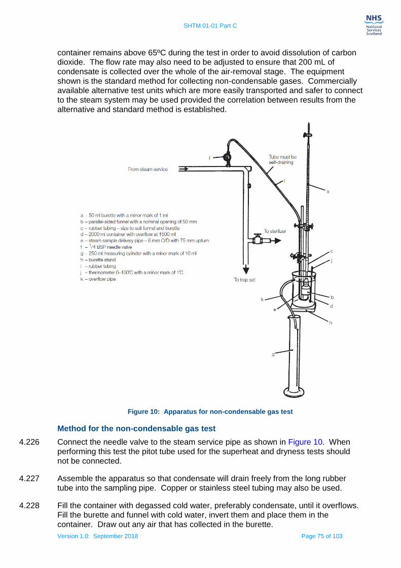
SHTM 01-01 Part C
Version 1.0: September 2018 Page 75 of 103
container remains above 65ºC during the test in order to avoid dissolution of carbon dioxide. The flow rate may also need to be adjusted to ensure that 200 mL of condensate is collected over the whole of the air-removal stage. The equipment shown is the standard method for collecting non-condensable gases. Commercially available alternative test units which are more easily transported and safer to connect to the steam system may be used provided the correlation between results from the alternative and standard method is established.
Figure 10: Apparatus for non-condensable gas test
Method for the non-condensable gas test
4.226 Connect the needle valve to the steam service pipe as shown in Figure 10. When
performing this test the pitot tube used for the superheat and dryness tests should not be connected.
4.227 Assemble the apparatus so that condensate will drain freely from the long rubber tube into the sampling pipe. Copper or stainless steel tubing may also be used.
4.228 Fill the container with degassed cold water, preferably condensate, until it overflows. Fill the burette and funnel with cold water, invert them and place them in the container. Draw out any air that has collected in the burette.

SHTM 01-01 Part C
Version 1.0: September 2018 Page 76 of 103
4.229 With the steam sampling pipe out of the container, open the needle valve and allow steam to purge the air from the pipe. Place the pipe in the container, locate the end within the funnel, and add more cold water until it flows through the overflow pipe.
4.230 Place the empty measuring cylinder under the container overflow.
4.231 Adjust the needle valve to allow a continuous sample of steam into the funnel sufficient to cause a small amount of steam hammer to be heard. Ensure that all the steam is discharged into the funnel and does not bubble out into the container. Record the setting of the needle valve. Close the valve.
4.232 Draw out any air present in the burette; ensure that the container is topped up with cold water and that the measuring cylinder is empty.
4.233 Ensure that the sterilizer chamber is empty except for the usual chamber furniture.
Select and start the operating cycle.
4.234 When the steam supply to the chamber first opens, open the needle valve to the previously recorded setting, allowing a continuous sample of steam into the funnel sufficient to cause a small amount of steam hammer to be heard.
4.235 Allow the steam sample to condense in the funnel. Any non-condensable gases will rise to the top of the burette. Overspill formed by the condensate and the water displaced by the gases will collect in the measuring cylinder.
4.236 When the temperature of the water in the container reaches 70–75ºC, close the needle valve. Record the volume of gas collected in the burette (Vb) and the volume of water collected in the measuring cylinder (Vc).
4.237 Calculate the fraction of non-condensable gases as a percentage as follows:
Fraction of non-condensable gases = 100 x Vb / (Vc – Vb)
Results from the non-condensable gas test
4.238 The test should be carried out twice further to check consistency. If the results of the three tests differ significantly, the cause should be investigated before proceeding further.
4.239 The test should be considered satisfactory if the maximum result of the 3 tests of the fraction of non-condensable gases does not exceed 3.5%.
Steam superheat test
4.240 This test is used to demonstrate that the amount of moisture in suspension with steam from the service supply is sufficient to prevent the steam from becoming superheated during expansion into the chamber. The test assumes that the steam supply pressure is nominally 4.0 bar gauge. If the supply pressure differs from this it may be necessary to amend the acceptance criteria accordingly.
4.241 The method described here uses a low-volume sample, continuously taken from the centre of the steam service pipe. The level of superheat determined by this method
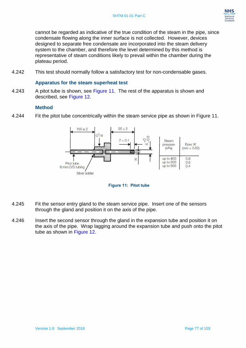
SHTM 01-01 Part C
Version 1.0: September 2018 Page 77 of 103
cannot be regarded as indicative of the true condition of the steam in the pipe, since condensate flowing along the inner surface is not collected. However, devices designed to separate free condensate are incorporated into the steam delivery system to the chamber, and therefore the level determined by this method is representative of steam conditions likely to prevail within the chamber during the plateau period.
4.242 This test should normally follow a satisfactory test for non-condensable gases.
Apparatus for the steam superheat test
4.243 A pitot tube is shown, see Figure 11. The rest of the apparatus is shown and described, see Figure 12.
Method
4.244 Fit the pitot tube concentrically within the steam service pipe as shown in Figure 11.
Figure 11: Pitot tube
4.245 Fit the sensor entry gland to the steam service pipe. Insert one of the sensors through the gland and position it on the axis of the pipe.
4.246 Insert the second sensor through the gland in the expansion tube and position it on the axis of the pipe. Wrap lagging around the expansion tube and push onto the pitot tube as shown in Figure 12.

SHTM 01-01 Part C
Version 1.0: September 2018 Page 78 of 103
Figure 12: Apparatus for superheat test
Ensure that the sterilizer chamber is empty except for the usual chamber furniture. Select and start the operating cycle.
4.247 From the measured temperatures, record the temperature in the steam service pipe (for use in the dryness test) and in the expansion tube (T) when the steam supply to the chamber first opens. Calculate the superheat in ºC from the following equation:
Superheat = T – T0,
where T0 is the boiling point of water at local atmospheric pressure.
Results of the steam superheat test
4.248 The test should be considered satisfactory if:
the superheat measured in the expansion tube does not exceed 25ºC;
the temperature measured in the steam pipe did not differ by more than 3ºC from that measured in the steam pipe during the steam quality, dryness test.
SHTM 01-01 Part C
Version 1.0: September 2018 Page 79 of 103
NOTE: This temperature is a parameter from which the variability of the steam pressure between sequential cycles can be assessed. A higher temperature difference can cause operational problems from the moisture content in the steam.
Steam dryness test
4.249 The accurate measurement of the percentage of moisture content in the steam is difficult, and the traditional methods, where constant steam flow is required, are not suitable for sterilizers. This test should be regarded not as measuring the true content of moisture in the steam, but as a method by which the provision of acceptable steam quality can be demonstrated. Possible sources of excessive moisture are discussed in paragraph 4.53 ‘Dryness’.
4.250 The test is carried out immediately after the superheat test.
Apparatus for the steam dryness test
4.251 A pitot tube is shown in Figure 11. The apparatus is shown and described, see Figure 13. All sizes are nominal.
4.252 A laboratory balance capable of weighing a load up to 2 kg with an accuracy of 0.1 g or better.
Method
4.253 If it is not already fitted, fit the pitot tube concentrically within the steam service pipe as shown in Figure 13.
4.254 If it is not already fitted, fit the sensor entry gland to the steam service pipe. Insert a temperature sensor through the gland and position it on the axis of the pipe.
4.255 Connect the rubber tube to the longer of the pipes in the stopper, place the stopper in the neck of the vacuum flask, weigh the whole assembly and record the mass (M1)
4.256 Remove stopper and tube assembly and pour 650+/- 50ml of cold water (below 27ºC) into the flask. Replace the stopper and tube assembly, weigh the flask and record the mass (M2).
4.257 Support the flask close to the pitot and ensure that the rubber tube and flask are protected from excess heat and draughts. Do not connect it to the pitot tube yet.

SHTM 01-01 Part C
Version 1.0: September 2018 Page 80 of 103
Figure 13: Apparatus for the steam dryness test
4.258 Introduce the second temperature sensor through the shorter of the two pipes in the stopper and into the water in the flask. Record the temperature of the water in the flask (T0).
4.259 Ensure that the sterilizer chamber is empty except for the usual chamber furniture. Select and start the operating cycle.
4.260 When the steam supply to the chamber first opens, connect the rubber tube to the pitot discharge and wrap lagging around it. Arrange the rubber tube to permit condensate to drain freely into the flask. Record the temperature in the steam service pipe (T0).
4.261 When the temperature of the water in the flask is approximately 80ºC, disconnect the rubber tube from the pitot, agitate the flask so that the contents are thoroughly mixed and record the temperature of the water (T1).
4.262 Weigh the flask and stopper assembly and record the mass (M3).
4.263 The initial mass of water in the flask is given by M= M2 – M1
4.264 The mass of condensate collected is given by M = M3 – M2
4.265 Calculate the dryness value of the steam from the following equation:

SHTM 01-01 Part C
Version 1.0: September 2018 Page 81 of 103
Where:
T0 = initial temperature of the water in the flask (ºC);
T1 = final temperature of the water and condensate in the flask (ºC);
T3 = average temperature of the steam delivered to the sterilizer (ºC);
Mw = initial mass of the water in the flask (kg);
Mc = mass of condensate collected (kg);
L = latent heat of dry saturated steam at temperature T8 (kJ kg1);
0.24 kJ kg1 = Effective heat capacity of the apparatus
Results of the steam dryness test
4.266 The test should be repeated 3 times and considered satisfactory if the following requirements are met:
the dryness value is not less than 0.95 unless only textile loads are being processed, in which case 0.90 is permissible;
throughout the operating cycle, the temperature measured in the steam service pipe is within 3ºC of that measured during the superheat test.

SHTM 01-01 Part C
Version 1.0: September 2018 Page 82 of 103
5. Operational management
The porous load cycle
5.1 Porous-load sterilizers heat load items of medical devices by direct contact with high-temperature steam once the air is removed at a typical sterilization temperature of 134ºC, see Table 1.
5.2 The operating cycle of a porous-load sterilizer normally has five stages:
1. Air removal – Sufficient air is removed from the chamber and the load to permit attainment of the sterilization conditions;
2. Steam admission – Steam is admitted to the chamber until the specified sterilization temperature is attained throughout the chamber and load;
3. Holding time – The temperature throughout the chamber and load is maintained within the sterilization temperature band for the appropriate holding time;
4. Drying – Steam is removed from the chamber and the chamber pressure is reduced to permit the evaporation of condensate from the load either by prolonged evacuation (normal/extended drying), or by the injection and extraction of hot air (pulsed drying). Note that for pulsed drying the quality of air admitted to the chamber must be controlled to avoid recontamination of the load, see note below;
5. Air admission – Air is admitted to the chamber until the chamber pressure attains atmospheric pressure, whereupon the door may be opened to allow removal of the load.
Note: the quality of air admitted to the chamber must be controlled to avoid recontamination of the load; this may be achieved via 0.3µm filter in accordance with EN ISO 285: 2015, clause 5.3.
5.3 The complete cycle time for a sterilization temperature of 134ºC is determined at the validation tests for the small and standard full load(s), but the drying stage(s) may need to be extended for loads of high heat capacity, or heavy density, such as trays of medical devices, that take longer to dry due to the increased condensate produced in the cycle.
Product compatibility with the porous load sterilizer
5.4 A porous-load sterilizer is suitable for processing a very wide range of medical devices and is the method of choice in most cases.
5.5 Medical devices to be processed in a porous-load sterilizer should have been
cleaned, disinfected and dried by a validated cleaning process as SHTM 01-01 Part A.
5.6 To reduce the possibility of superheating, load items consisting of textiles should be allowed to air for a period of not less than four hours after laundering.
Medical devices that should not be processed in a porous load sterilizer
5.7 The following should not be processed in a porous-load sterilizer:
SHTM 01-01 Part C
Version 1.0: September 2018 Page 83 of 103
medical devices that would be damaged by exposure to moist heat at 121–137ºC;
medical devices that would be damaged by rapid pressure changes;
medical devices in impermeable containers or packaging (air will not be extracted);
where the medical device manufacturer’s instructions for use state processing with a porous load sterilizer would be incompatible with their medical device.
Cycle monitoring and documentation
5.8 Settings for the automatic controller will be determined during performance qualification.
5.9 Generally, these will consist of a chamber temperature within the sterilization
temperature band and a plateau period designed to accommodate the equilibration time and the holding time. Guidance on the cycle variables can be found in paragraph 5.2.
5.10 It is vital that every production cycle is monitored and documented and that records are kept securely. Guidance on record-keeping is given in paragraph 5.26 ‘Record-keeping’.
5.11 The sterilizer process log for each sterilized load should include as a minimum:
sufficient information to identify the sterilizer (by a unique reference number; by the name of the manufacturer, the model of sterilizer and the serial number; or by any sufficient combination of these);
a specification of the loading condition (defined either by the nature and number of load items of packaged medical devices, items of chamber furniture and their distribution in the chamber, or by a coded reference to a detailed specification held elsewhere);
a specification of the operating cycle (defined either by the settings for the cycle variables or by a coded reference to a detailed specification held as part of the quality management system);
a reference to the result of any routine preproduction test, such as a Bowie and Dick test;
independent monitoring data to be compared to sterilizer cycle records to confirm particular cycle profiles in relation to validated parameter limits;
any deviations from the PQ specification in terms of loading condition and settings of cycle variables whether or not these result in an acceptable cycle;
the date and time of the start of the operating cycle;
the cycle number as indicated on the cycle counter/display;
the name or other identification of the operator.
5.12 The batch process record (BPR) obtained from the sterilizer’s recorder/independent monitor should be sufficiently detailed to confirm that the recommendations for critical

SHTM 01-01 Part C
Version 1.0: September 2018 Page 84 of 103
parts of the operating cycle are met. This is best achieved by ensuring that a continuous graph is plotted as the cycle progresses and, for a digital system, that the values of all samples are retained for later inspection.
5.13 Biological indicators are not required for monitoring of steam processes, although they may occasionally be necessary for PQ of unusual loads.
5.14 Failed cycles for any reason should be noted in the sterilizer process log along with any remedial action taken. Operators should be encouraged to note and report any observations that suggest that the sterilizer may not be working as it should be.
5.15 Where a load has been reprocessed following the failure of an earlier cycle, records of the original cycle should be readily traceable from the reprocessing records.
5.16 If in doubt about which records are needed, the User should consult the CP(D),
AP(D) and the AE(D). It should be possible to trace any sterilized medical devices from the point of use back through the supply chain to the specific sterilizer and cycle in which they were processed and establish the precise values of the cycle variables throughout the cycle. Further guidance on traceability is provided in Part A of this SHTM 01-01.
Sterile product release
5.17 A fool proof system to differentiate between processed and unprocessed load items of medical devices should be used. A convenient method is to use chemical indicators that change colour on exposure to the sterilization process. Such process indicators are available in a variety of forms including adhesive tape, labels and pre-printed panels on sterilization packaging. Process indicators should conform to the specifications for Class 1 indicators given in EN ISO 11140-1: 2014.
5.18 Users should note that process indicators only demonstrate that the load items of medical devices have been exposed to an operating cycle.
Note: It is essential that such process indicators are only used for their intended purpose, and not misused e.g. indicator tape must not be used as general purpose
adhesive tape post sterilization.
5.19 The User should establish and document procedures to ensure that loads are not released for use until the User is satisfied that the operating cycle has been reproduced within the permitted tolerances established during PQ.
5.20 The procedures should confirm the following:
that the sterilizer has been loaded as local policies and in conjunction with the PQ specification;
that the settings for the operating cycle were in accordance with the PQ specification;
that the Batch Process Record (BPR) for the cycle conforms with the relevant Master Process Record (MPR) within the permitted tolerances (see previous paragraph);

SHTM 01-01 Part C
Version 1.0: September 2018 Page 85 of 103
that any indicated readings needing to be noted during the cycle have been noted and are in accordance with the PQ specification (The Independent Monitoring System (IMS) data should also be considered);
that the sterilized load shows no obvious anomalies, such as damaged packaging or containers, which could suggest a faulty cycle;
the load items of packaged medical devices are visibly dry.
5.21 Regardless of the above procedure, whenever an Operator has cause to suspect that the load may not have been properly sterilized, the load should not be released. The User should be informed immediately. If there appears to be any problems with equipment the AP(D) should be consulted.
Rejected loads
5.22 Failure to meet any of the sterile product release requirements should lead to the load being rejected placed in quarantine and the cause of the failure investigated. The investigation should be documented and the handling of the product should be in accordance with the procedures for control of non-conforming product required by EN ISO 13485 and SHTM01-01 Part A.
5.23 Documented procedures for dealing with rejected loads should be documented in the CDU’s Quality management system.
5.24 Procedures for the disposal of a discarded load should ensure that no hazard is caused either to personnel or to the environment.
Sterile product storage
5.25 After sterilization and before use, conditions for sterile product storage and handling should not compromise the qualities of the sterile product.
Note: See Scottish Health Planning Note 13 Part 1 Decontamination Facilities: Central Decontamination Unit for reference and GUID 5010 – ‘Theatres and CDU guidance – Management of reusable surgical instruments during transport, storage and after clinical use’ published by HFS 2014.
Record-keeping
5.26 Complete and accurate records are an essential element in ensuring the safe and efficient functioning of sterilizers and compliance with regulatory requirements. Where electronic tracking systems (preferably compatible with GS1) are used to retain data, a routine audit should be carried out on databases to ensure information is securely stored and available to be easily retrieved where required.
5.27 The following principles, for quality control of sterilization processes. Records should:
be original (not a transcription), indelible, legible and dated;
be made concurrently with the performance of each operation and test;
identify the person recording the data as well as the person checking the data or authorizing continuation of processing;
SHTM 01-01 Part C
Version 1.0: September 2018 Page 86 of 103
be detailed enough to allow a clear reconstruction and understanding of all relevant procedures performed;
allow tracing of all successive steps and identify the interrelationships of dependent procedures, products and waste materials;
be maintained in an orderly fashion permitting the retrieval of data for a period consistent with dating periods (shelf life) and legal requirements;
indicate that processing and testing were carried out in accordance with procedures established and approved by management;
if necessary, allow a prompt and complete recall of any particular batch;
show the lot numbers of materials used for making up specified batches of processed medical devices.
5.28 The system recommended in this guidance requires two sets of records to be kept for each sterilizer:
a plant history file;
a sterilizer process log.
5.29 The sterilizer records are the responsibility of the User. They should be made available to any other personnel who need to use them. This will include the AE(D), AP(D), CP(D), CP(PS), the Microbiologist and Infection Control. Records shall be retained for a period of not less than 11 years in accordance with EN ISO 285, and local requirements according to Scottish Government Records Management: NHS Code of Practice (Scotland). EN 13485: 2016 section 4.2.5 states “The organization shall retain the records for at least the lifetime of the medical device as defined by the organization, or as specified by applicable regulatory requirements, but not less than two years from the medical device release by the organization”.
Sterilizer plant history file
5.30 The plant history file contains engineering records of the sterilizer installation. It should be kept throughout the life of the sterilizer. Examples, of the information that should be kept in the plant history file include:
identification of the sterilizer;
names, addresses and telephone numbers of the sterilizer manufacturer, owner and key personnel (User, AE(D), AP(D), CP(D), CP(PS), Microbiologist);
dates of installation and commissioning;
validation procedures;
validation reports (including PQ reports for each loading condition);
copies of validation summary sheets;
copy of any maintenance contract;
planned maintenance programme including detailed procedures for all maintenance tasks;

SHTM 01-01 Part C
Version 1.0: September 2018 Page 87 of 103
records of maintenance, both scheduled and unscheduled, sufficient to show that all examinations, tests and checks have been carried out;
manuals supplied by the manufacturer;
documentation for any software used for control or instrumentation (including the name of an agent where the source codes may be obtained should the manufacturer cease trading);
the written scheme of examination for any pressure vessel;
reports by the CP(PS) in respect of pressure systems;
data from periodic tests carried out by the CP(D);
copies of data from the periodic tests carried out by the User (kept in the sterilizer process log);
records of any defects found on the sterilizer and corrective action taken;
records of any modification made to the sterilizer;
references to the plant history files for the test instruments used in the validation and periodic tests;
specifications for the operating cycles;
sterilizer capacity, chamber size in litres;
control system fitted and software serial code and version number;
recorder/independent monitor fitted, make model and type and software serial code and version number;
any IT systems fitted or tracking system details;
last test date, whether annual or quarterly thermometric test.
Sterilizer process log book
5.31 The sterilizer process log book contains information required for routine operation of the sterilizer and records relevant to each cycle. It should contain the following information:
identification of the sterilizer;
names, addresses and telephone numbers of the sterilizer manufacturer, owner and key personnel (User, AE(D), AP(D), CP(D), CP(PS), Microbiologist);
names of authorised Operators;
written procedures for all duties to be carried out by the Operators;
full operating instructions;
copies of validation summary sheets, see Section 3 ‘Validation and verification’;
data from the periodic tests carried out by the user;
records of routine housekeeping carried out by the User, see paragraph 5.41 ‘Planned maintenance programme’;
specifications for the operating cycles for which the sterilizer has been validated, defined by the settings for the cycle variables;

SHTM 01-01 Part C
Version 1.0: September 2018 Page 88 of 103
specifications for the loading conditions for which the sterilizer has been validated, defined by the nature and number of load items of packaged medical devices, items of chamber furniture, and their distribution within the chamber.
5.32 The following information should be noted (electronic tracking system) for each batch processed by the sterilizer:
the name of the Operator;
the date and time of the start of the cycle;
the cycle number;
a reference to the loading condition;
a reference to the operating cycle;
a specification of any preconditioning, conditioning or degassing process;
reference number of the Master Processing Record (MPR);
values of cycle variables needing observation and noted by the Operator during the cycle;
confirm whether or not the cycle was satisfactory;
sterilizer identification;
batch number.
5.33 The BPR for each cycle should be filed in such a way that it can be readily retrieved for inspection. Before filing it should be clearly marked with the following:
sterilizer identification;
date;
cycle number;
batch number;
reference number of the MPR;
confirm whether or not the cycle was satisfactory.
5.34 Other guidelines for entries in the sterilizer process log may be found in paragraph 5.1.
Maintenance of the sterilizer
5.35 The efficacy of sterilization cannot be verified retrospectively by inspection or testing of the processed medical devices before use. For this reason, decontamination processes should be validated before use, the performance of the process routinely monitored and the equipment maintained.
5.36 Means of ensuring that a sterilizer is fit for its intended purpose will include the validation and testing programme specified in Section 3 ‘Validation and verification’,

SHTM 01-01 Part C
Version 1.0: September 2018 Page 89 of 103
and also the programme of planned maintenance as described in this section.
5.37 The philosophy of maintenance and testing embodies two main principles to ensure that the required standards of performance and safety are met and maintained:
all sterilizers are subject to a carefully planned programme of tests to monitor their performance;
all sterilizers are subjected to a planned programme of preventative maintenance.
5.38 The sterilizer manufacturer defines the maintenance requirements in their instructions for use. Health Board expertise on the maintenance of sterilizers is available at three levels:
the CP(D);
the AP(D);
the AE(D).
5.39 Refer to SHTM 01-01 Part A for roles and responsibilities which describes these three roles.
5.40 The testing of sterilizers is dealt with in Section 3 ‘Validation and verification’.
Planned maintenance (PM) programme
5.41 The planned maintenance programme should be designed according to the following principles:
all parts of the sterilizer that are vital to correct functioning or safety should be tested at weekly intervals, meaning:
there is no need to test components individually in those cases where any malfunction will be revealed by the periodic tests outlined in Section 3 ‘Validation and verification’, for weekly or more frequent intervals;
where the correct functioning of important components is not necessarily verified by the periodic tests prescribed for the sterilizer, those components should be individually tested each week and reference to testing them should be included in the schedules of maintenance tasks. This applies, for example, to door interlocks that may only have their safety function activated when there is an abnormal condition;
the maintenance programme should include, at appropriate intervals, those tasks such as lubrication and occasional dismantling of particular components (such as pumps) necessitated by normal good practice, manufacturer’s advice and experience. Apart from those tasks, the maintenance programme should concentrate on verifying the condition of the sterilizer and its components by means of testing and examination without dismantling. Parts that are working correctly should not be touched unnecessarily;
maintenance should be carried out under a quality system such as EN ISO 9001. Spares fitted to sterilizers constructed under a quality system should be sourced from a similarly approved quality system.
SHTM 01-01 Part C
Version 1.0: September 2018 Page 90 of 103
Design of a PM programme
5.42 The PM programme recommended by the manufacturer should be used when it is available. The maintenance programme can be modified subsequently to take account of equipment use, equipment history and local conditions after a suitable period of operational experience.
5.43 If no PM programme is available from the manufacturer, a maintenance programme should be drawn up in consultation with the AE(D), the AP(D) and CP(D).
5.44 Although the manufacturer can carry out certain inspection and maintenance procedures under the terms of the warranty, these may not constitute a full PM programme. The User should therefore ensure that the complete PM programme is carried out by the CP(D) (who can be an employee of the manufacturer) – see paragraph 5.54 regarding the warranty period. The User should also implement any reasonable instructions given by the manufacturer during this period. Failure to carry out maintenance tasks and periodic tests could affect safety. It could also allow a contractor to place some, if not all liability on to management. Where maintenance is carried out under a lump sum term contract, such failure is tantamount to a breach of contract and can give the contractor cause to terminate the contract, if desired.
5.45 A set of procedures should be developed for each model of sterilizer, each containing full instructions for a particular maintenance task.
5.46 The frequency with which each task will need to be carried out will depend, in part, on the usage level for the machine and also on the quality of the water/steam supplied to the machine. It may be necessary to adjust the programme so that work is carried out more frequently on machines that are heavily used and/or are supplied with hard water.
5.47 It is important that maintenance is planned so that the machine is out of service as little as possible. Maintenance should, where practicable, be scheduled to precede the periodic tests immediately as specified in Section 3 ‘Validation and verification’.
5.48 Systematic records should be kept of all maintenance work undertaken both to demonstrate that the work has been carried out and also to facilitate a periodic review of the PM programme.
5.49 Maintenance and facilities management software packages can be used to maintain a full technical and financial history of the equipment.
Review of a PM programme
5.50 The PM programme should be reviewed, either within a routine internal/external audit process or as part of the AE(D) assessment, at least annually to ensure that the equipment is being fully maintained but without any unnecessary maintenance activity.
5.51 The review should aim to identify:
the adequacy of maintenance records and compliance with the PM programme;
any emerging defects;

SHTM 01-01 Part C
Version 1.0: September 2018 Page 91 of 103
any changes required to the PM programme;
any changes required to any maintenance procedure;
any additional training required by maintenance personnel.
5.52 Proposed changes to the PM programme should be made in consultation with the manufacturer wherever possible.
Modifications to sterilizer
5.53 Occasionally, modifications to the machine may be recommended by the manufacturer or by NHSScotland for reasons of efficacy and safety. The User should arrange for such modifications to be carried out within a reasonable period, normally coinciding with a scheduled maintenance session. The AE(D) should advise whether any revalidation is required depending on the nature of the
modification.
Warranty period
5.54 After the purchase of a new machine, the manufacturer can carry out certain inspection and maintenance procedures under the terms of the warranty. This may not be a full PM programme. If so the User should ensure that the complete PM programme is carried out by the CP(D) during the warranty period.
5.55 The User should also follow any reasonable instructions from the manufacturer during the warranty period.
Note: Agreement must be established with the manufacturer and the User to establish the start date of the warranty period and a clear time of completion.
Features requiring special attention
Chambers
5.56 Chambers should be maintained in good condition following manufacturer’s instructions.
Airtightness of the chamber
5.57 Airtightness of the chamber is of fundamental importance to the correct functioning of sterilizers. The door seal is the major potential source of leakage and should receive careful attention as advised by the manufacturer. The working life of door seals varies widely and it is essential that all seals are cleaned regularly. Door seals should be renewed with spares approved by the manufacturer at recommended
intervals, or when there is any evidence of damage or deterioration.
5.58 Leaks may also occur in the following places:
joints in pipework;
connections to gauges;
blanked-off connections for test gauges;
entry points for temperature and pressure sensors (whether in use or blanked off);

SHTM 01-01 Part C
Version 1.0: September 2018 Page 92 of 103
glands and seats of valves;
cracks in chamber welds or platework;
pinholes in pipework and fittings;
holes in condenser tubes.
5.59 Particular care should be taken when installing, removing or adjusting any part of an air detector. The sensitivity of the air detector should be adjusted in accordance with the manufacturer’s instructions and the setting determined during validation.
5.60 The air detector should not be removed or adjusted except for essential repair and replacement. Following any such action the AE(D) should advise revalidation tests required, see 5.72.
5.61 If it has been necessary to adjust the air detector, the CP(D) should carry out re-
validation tests as described in Section 3 ‘Validation and verification’.
Ancillary equipment
5.62 Ancillary equipment used in conjunction with the sterilizer should also be subject to planned maintenance in accordance with the manufacturer’s instructions.
5.63 Where the maintenance of ancillary equipment is not the responsibility of the User, arrangements should be made to give the User reasonable notice of all periods of maintenance (whether scheduled or not) and of impending modifications to any part of the equipment. The User should also have access to maintenance records.
5.64 Examples of ancillary equipment include:
all engineering services to the sterilizer, especially steam;
dedicated steam generators, see paragraph 4.100 ‘Steam from a dedicated generator’);
sterilizer furniture ( loading cart, racks and automatic loading equipment);
room ventilation and local exhaust ventilation (see Scottish Health Technical Memorandum 03-01 ‘Ventilation for healthcare premises');
Personal Protective Equipment (PPE);
air compressors and potable water pumps.
5.65 Consideration should be given to the introduction of a permit to work system for the maintenance of ancillary equipment.
Sterilizer instruments
5.66 Instruments fitted to sterilizers should be maintained and calibrated in accordance with the manufacturer’s instructions. Calibration should be verified at the normal sterilization temperature and pressure and at stable ambient temperatures. Any sterilizer instrument found to read in error or which is inconsistent, i.e. will not repeat satisfactorily, should be discarded, or repaired by the manufacturer or their appointed agent.

SHTM 01-01 Part C
Version 1.0: September 2018 Page 93 of 103
5.67 A sterilizer instrument case should never be left open; broken glass should be replaced promptly.
5.68 The recorder/independent monitoring system is an essential monitor of the general functioning and performance of a sterilizer. Temperature measuring systems are subject to both inherent calibration errors and loss of calibration with use. As a consequence temperatures read from a recorder/independent monitor should be regarded with caution and interpreted from knowledge of the characteristics of the particular recording system, the load and previous records.
5.69 It is essential that calibrated instruments and independent monitoring system are not adjusted unless absolutely necessary – any adjustments to be made by trained, competent staff in accordance with manufacturer’s instructions using reference equipment having calibration traceable to the National Standard, and detail of adjustments recorded i.e.; before (as found) / after readings. This is applicable to any process critical measurement e.g.; temperature, pressure, time.
5.70 Persons who change charts, print rolls and other consumables on recording instruments should be trained, made fully aware of the delicate nature of the instruments and authorised by the User.
Returning a sterilizer to service
5.71 The User, with the assistance of the AE(D) and AP(D), should prepare an operational procedure for the return to service of a sterilizer after maintenance or testing. The procedure should include safety checks and some or all of the re-validation (yearly) tests specified in Section 3 ‘Validation and verification’.
5.72 The CP(D) should certify that the work has been completed and that the sterilizer is safe to use. (See guidance on permits-to-work found in SHTM 01-01 Part A)
5.73 The User should ensure that a sterilizer is not used for production until all required maintenance has been successfully completed.
Troubleshooting
Wet loads
5.74 Wet loads can be defined in different ways depending on where moisture can be found. Validation will determine the acceptability of drying test and PQ loads. If water is present in the load, even if the outer packaging is not wet at the time of inspection, it could contaminate the packaging and render it transparent to microbial penetration.
5.75 If wet loads are experienced the situation should be investigated and rectified.
5.76 Wet loads may have a number of causes. These can include one or a combination of any of the following:
nature of the load, for example high mass and/or low thermal conductivity materials;
poor drainage of loading systems and containers;
SHTM 01-01 Part C
Version 1.0: September 2018 Page 94 of 103
steam trap failures on the sterilizers or steam supply;
insufficient steam jacket performance (including blockages, drainage or trapping);
packaging materials (including poor wrapping technique or selection of materials used);
overloading of sterilizer;
poor sterilizer drying performance;
steam with a low dryness.
5.77 In order to dry the load efficiently it is necessary to either remove condensate during the cycle or retain it at its point of creation so that it may regain residual heat during the drying stage.
5.78 Any packaged medical device with wet outer packaging should be rejected since the moisture compromises the protective qualities of the sterile barrier system and microbial contamination could occur.
5.79 Wet spots or patches on the packaging show that liquid water has been drawn into the chamber. There are several possible explanations, including:
poorly draining steam traps between the sterilizer and boiler (a sudden demand for steam can draw water out of a full trap);
severe pressure fluctuations in the main;
priming of the boiler leading to carry-over of water in the steam.
5.80 Occasionally, packaged medical devices with dry outer packaging can be found to be wet inside. While the sterility of the product may be satisfactory, there remains the possibility that the load was wet throughout at some stage and therefore sterility cannot be assured.
5.81 Packages that are damp inside are often the result of inadequate packaging and loading, especially when metal objects have been processed. If the precautions outlined above have been followed, however, the cause may be a wet steam supply. This can be confirmed by the steam dryness test described in Section 3 ‘Validation and verification’. Users should note that this test will not reliably detect wetness due to sporadic carryover of water. This can also be seen as water droplets on the wrapping - ‘‘water spotting’’.
5.82 Paragraph 4.1 ‘Steam supply’ describes the engineering requirements for a steam supply of the correct dryness for sterilization. The sudden appearance of wet loads from a loading condition and operating cycle that has been used successfully for a long time can indicate a change in the steam service. For example, there may be a fault somewhere in the system or engineering modifications to the steam service; new or modified boilers, extensions to the steam main, and new equipment installed elsewhere can all affect the dryness of the steam supplied to the sterilizer.
SHTM 01-01 Part C
Version 1.0: September 2018 Page 95 of 103
Spontaneous combustion
5.83 There have been reports of textile loads bursting into flame within the sterilizer chamber. Invariably this is because the load has been allowed to become excessively dry and hot. There are two circumstances in which this can occur:
the load is placed in a heated chamber and left for a considerable time before the cycle is started; ignition is believed to occur when the load becomes rehydrated on the introduction of steam to the chamber;
the load is left inside the chamber for a long time after the end of the operating cycle; ignition occurs when the door is opened and the load is exposed to air. This is most likely to happen where the operating cycle has aborted due to a fault condition and the load is not removed promptly.
5.84 Users should be mindful of this risk and establish operating procedures to ensure
that loads are not left in heated chambers for longer than necessary.
The use of metal containers within a porous load sterilizer
5.85 The use of metal containers is becoming more widespread throughout NHSScotland, especially in loan equipment and orthopaedic medical devices. Healthcare organisations contemplating the use of metal containers should consider the points listed in, and containers must be used with a validated procedure. See SHTM 01-01 Part F.
5.86 Where metal containers are used within a department, such use must be planned carefully as the containers need to be cleaned and washed to the same standard as the medical devices they contain. This will require an increase in washer disinfector capacity (approximately 40% increase in chamber or machine capacity).
5.87 When contemplating the use of metal containers, the following points should be considered:
the handling and weight increases in alignment with local manual handling policy – risk analysis;
the need to request sterility test results or control methods from the manufacturer;
the recommended periods of seal replacement in alignment with manufacturers’ recommendations;
the recommended period of filter replacement and housing details;
the need to carry out tests to check for any deformities of container bases or lids (jigs);
the need for identification of seal container – tag type system;
the need to wrap containers in order to include a dust layer or comply with theatre handling policies.
5.88 At the time of writing this guidance, there are few reliable methods for ensuring that the filter[s] are secure in the fixings, or that the seal between the container and the lid is sufficient. The container manufacturer should be asked to supply a validated

SHTM 01-01 Part C
Version 1.0: September 2018 Page 96 of 103
method for checking and testing the container and a schedule of planned maintenance. See SHTM 01-01 Part F.
5.89 Prior to introducing such systems, healthcare organisations should undertake a documented risk assessment in accordance with EN ISO 14971.
Sterilizer loading carriages
5.90 The inclusion of drip deflectors between tiers of medical device trays can assist in preventing condensate dripping from one shelf to another. However, the design of the deflectors is critical in order to consistently achieve the required conditions on cycle conclusion. Aluminium deflectors are usually more effective than stainless steel.
5.91 Shelving should be an open mesh design rather than solid sheet.
5.92 Any changes to wrapping materials and chamber carriages should only be carried out after undergoing a validated process. The User should consult with the AE(D) prior to introducing such changes. Any such changes can potentially reduce the effectiveness of air removal, prevent sterilization at all points of the load and result in the release of a load that that has not been sterilized to the required standard.

SHTM 01-01 Part C
Version 1.0: September 2018 Page 97 of 103
Appendix A: Saturated steam tables
Saturated steam tables calculated according to EN 285: 2015 clause 8.2.1.2.3, and CEN ISO/TS 17665-2:2009 Annex C:
Equation: T = 42.6776 + [−3 892.7 / (logeP −9.48654)] −273.27
Where:
T is the theoretical steam temperature, in degrees centigrade (°C);
P is the measured pressure, in mega Pascals (MPa);
loge denotes the natural logarithm (ln) as used in the relevant Standards)
−273.27 °C is used for the value of absolute zero (zero K) for derivation of Table A1 below and A2 following
Linear interpolation between data points may be used to derive intermediate values.
MEASURED PRESSURE → TEMPERATURE
Measured Pressure mbarA MPa Temp °C
1000 0.1 99.6
1050 0.105 101
1100 0.11 102.3
1150 0.115 103.6
1200 0.12 104.8
1250 0.125 106
1300 0.13 107.1
1350 0.135 108.2
1400 0.14 109.3
1450 0.145 110.3
1500 0.15 111.4
1550 0.155 112.4
1600 0.16 113.3
1650 0.165 114.2
1700 0.17 115.2
1750 0.175 116.1
1800 0.18 116.9
1850 0.185 117.8
1900 0.19 118.6
1950 0.195 119.4
2000 0.2 120.2
2050 0.205 121
2100 0.21 121.8
2150 0.215 122.5
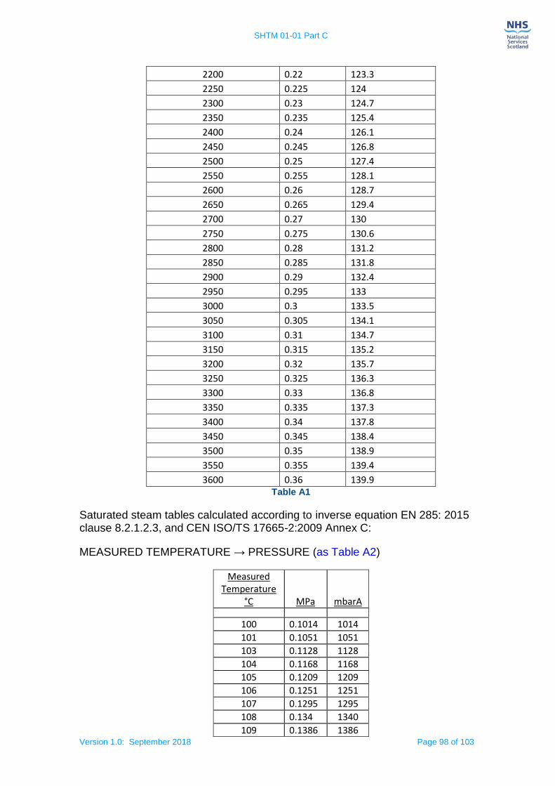
SHTM 01-01 Part C
Version 1.0: September 2018 Page 98 of 103
2200 0.22 123.3
2250 0.225 124
2300 0.23 124.7
2350 0.235 125.4
2400 0.24 126.1
2450 0.245 126.8
2500 0.25 127.4
2550 0.255 128.1
2600 0.26 128.7
2650 0.265 129.4
2700 0.27 130
2750 0.275 130.6
2800 0.28 131.2
2850 0.285 131.8
2900 0.29 132.4
2950 0.295 133
3000 0.3 133.5
3050 0.305 134.1
3100 0.31 134.7
3150 0.315 135.2
3200 0.32 135.7
3250 0.325 136.3
3300 0.33 136.8
3350 0.335 137.3
3400 0.34 137.8
3450 0.345 138.4
3500 0.35 138.9
3550 0.355 139.4
3600 0.36 139.9 Table A1
Saturated steam tables calculated according to inverse equation EN 285: 2015 clause 8.2.1.2.3, and CEN ISO/TS 17665-2:2009 Annex C:
MEASURED TEMPERATURE → PRESSURE (as Table A2)
Measured Temperature
°C MPa mbarA
100 0.1014 1014 101 0.1051 1051 103 0.1128 1128 104 0.1168 1168 105 0.1209 1209 106 0.1251 1251 107 0.1295 1295 108 0.134 1340 109 0.1386 1386
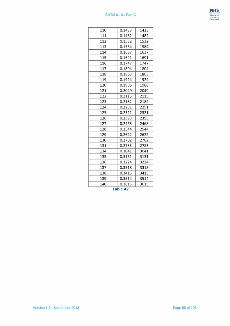
SHTM 01-01 Part C
Version 1.0: September 2018 Page 99 of 103
110 0.1433 1433 111 0.1482 1482 112 0.1532 1532 113 0.1584 1584 114 0.1637 1637 115 0.1691 1691 116 0.1747 1747 117 0.1804 1804 118 0.1863 1863 119 0.1924 1924 120 0.1986 1986 121 0.2049 2049 122 0.2115 2115 123 0.2182 2182 124 0.2251 2251 125 0.2321 2321 126 0.2393 2393 127 0.2468 2468 128 0.2544 2544 129 0.2622 2622 130 0.2702 2702 131 0.2783 2783 134 0.3041 3041 135 0.3131 3131 136 0.3224 3224 137 0.3318 3318 138 0.3415 3415 139 0.3514 3514 140 0.3615 3615
Table A2
SHTM 01-01 Part C
Version 1.0: September 2018 Page 100 of 103
References
These references were current at the time this document was produced. Anyone using this document should ensure that they refer to the current versions of any references.
Government publications
NHS HDL (2003) 42 Decontamination – NHS Scotland Sterile Services Provision Review Group (Glennie Group), SEHD.
NHS HDL (2002) 67 Decontamination – NHS Scotland Sterile Services Provision Review Group, SEHD.
NHS HDL (2001) 66 Healthcare Associated Infection: Review of Decontamination Services and Provision across NHS Scotland, SEHD.
NHS HDL (2001) 10 Decontamination of Medical Devices, SEHD.
Sterile Services Provision Review Group – 1st Report 2001, SEHD.
Acts and Regulations
Regulation (EU) 2017/745 on medical devices
Regulation on Control of substances hazardous to health (COSHH) 2002
Control of Noise at Work Regulations 2005.
Control of Substances Hazardous to Health Regulations 2002, SI 1999 No
Health & Safety at Work etc Act 1974, HMSO.
(The) Management of Health and Safety at Work Regulations 1999, SI 1999
No. 2051, HMSO.
Pressure Equipment Regulations 1999. SI 1999 No 2001. HMSO, 1999.
Pressure Systems Safety Regulations 2000. SI 2000 No 128.
(The) Provision and Use of Work Equipment Regulations 1998, SI 1998 No
2306, HMSO.
Simple Pressure Vessels (Safety) Regulations 1991. SI 1991 No 2749.
HMSO, 1991.
Sewerage (Scotland) Act 1968 (as amended 2002)
European Standards/Test specifications

SHTM 01-01 Part C
Version 1.0: September 2018 Page 101 of 103
EN 13485: 2016 Medical Devices. Quality management systems. Requirements for regulatory purposes. CEN.
EN ISO 17664: 2004 Sterilization of medical devices — Information to be provided by the manufacturer for the processing of resterilizable medical devices. CEN.
EN ISO 17664: 2017 Processing of health care products. Information to be provided by the medical device manufacturer for the processing of medical devices. CEN.
EN ISO 11607-1: 2017 Packaging for terminally sterilized medical devices. Requirements for materials, sterile barrier systems and packaging systems. CEN.
EN ISO 11607-2: 2017 Packaging for terminally sterilized medical devices. CEN.
CEN ISO/TS 16775: 2014 - Packaging for terminally sterilized medical devices - Guidance on the application of ISO 11607-1 and ISO 11607-2 (ISO/TS 16775:2014). CEN.
EN ISO 868-3: 2017. Packaging for terminally sterilized medical devices. Paper for use in the manufacture of paper bags (specified in EN 868-4) and in the manufacture of pouches and reels (specified in EN 868-5) Requirements and test methods. CEN.
EN ISO 15223-1: 2016 Medical devices - Symbols to be used with medical device labels, labeling and information to be supplied - Part 1: General requirements. CEN.
EN ISO 14644-4: 2001 Cleanrooms and associated controlled environments. Design, construction and start-up. CEN.
EN ISO 14644-2: 2015 Cleanrooms and associated controlled environments. Specifications for testing and monitoring to prove continued compliance with ISO 14644-1. CEN.
EN 285: 2006+A2:2015 Sterilization. Steam sterilizers. Large sterilizers. CEN.
EN ISO 17665-1: 2006 Sterilization of health care products — Moist heat — Part 1: Requirements for the development, validation and routine control of a sterilization process for medical devices. CEN.
EN ISO 14971: 2012 Medical devices — Application of risk management to medical devices. CEN.
EN 556-1: 2001 Sterilization of medical devices. Requirements for medical devices to be designated "STERILE". Requirements for terminally sterilized medical devices.
CEN.
EN ISO 11140-1: 2014 Sterilization of health care products. Chemical indicators. General requirements. CEN.
EN ISO 11140-3: 2009 Sterilization of health care products. Chemical indicators. Class 2 indicator systems for use in the Bowie and Dick-type steam penetration test. CEN.
SHTM 01-01 Part C
Version 1.0: September 2018 Page 102 of 103
EN ISO 11140-4: 2007 Sterilization of health care products. Chemical indicators. Class 2 indicators as an alternative to the Bowie and Dick-type test for detection of steam penetration. CEN.
EN ISO 15882: 2008 Sterilization of health care products — Chemical indicators — Guidance for selection, use and interpretation of results (ISO 15882:2008). CEN.
EN ISO 18472: 2006 Sterilization of health care products. Biological and chemical indicators. Test equipment and methods. CEN.
EN 61010-1: 2001, IEC 61010-1: 2001 Safety requirements for electrical equipment for measurement, control and laboratory use. General requirements. CEN.
EN 61000-6-1: 2007 - Electromagnetic compatibility (EMC). Generic standards. Immunity for residential, commercial and light-industrial environments. CEN.
EN 61000-6-3: 2011 - Electromagnetic compatibility (EMC). Generic standards. Emission standard for residential, commercial and light-industrial environments. CEN.
EN 61508 series: 2010 - Functional safety of electrical/electronic/ programmable electronic safety-related systems. CEN.
EN 61672-1: 2013 - Electroacoustics. Sound level meters. Specifications. CEN.
EN 61672-2: 2017 - Electroacoustics. Sound level meters. Pattern evaluation tests. CEN.
CEN ISO/ TS 17665 Part 2: 2009 Sterilization of health care products. Moist heat. Guidance on the application of ISO 17665-1. CEN.
PD ISO/ TS 17665 Part 3: 2013 Sterilization of health care products. Moist heat. Guidance on the designation of a medical device to a product family and processing category for steam sterilization. CEN.
EN ISO/IEC 17025: 2017 General requirements for the competence of testing and calibration laboratories. CEN.
EN ISO 384: 2015 - Laboratory glass and plastics ware. Principles of design and construction of volumetric instruments. CEN.
EN ISO 4064-1: 2017 - Water meters for cold potable water and hot water. Metrological and technical requirements. CEN.
Health Facilities Scotland publications
Scottish Health Technical Memorandum (SHTM) 01-01 Decontamination of medical devices in a Central Decontamination Unit - Part A: Management, 2018.
Scottish Health Technical Memorandum (SHTM) 01-01 Decontamination of medical devices in a Central Decontamination Unit - Part B: Test Equipment, 2018.
SHTM 01-01 Part C
Version 1.0: September 2018 Page 103 of 103
Scottish Health Technical Memorandum (SHTM) 01-01 Decontamination of medical devices in a Central Decontamination Unit - Part D: Automated cleaning and disinfection equipment, 2018.
Scottish Health Technical Memorandum (SHTM) 01-01 Decontamination of medical devices in a Central Decontamination Unit - Part E: Sterilization by Hydrogen Peroxide or Ethylene Oxide, 2018
Scottish Health Technical Memorandum (SHTM) 01-01 Decontamination of medical devices in a Central Decontamination Unit Part F: Inspect, Assemble and Package, 2018.
Roles and responsibilities of NHSScotland Decontamination Engineering staff in the acute sector – GUID 5015, February 2017.
Requirements for compliant Central Decontamination Units – GUID 5014, November 2016.
Scottish Health Planning Note 13 Part 1: Decontamination Facilities: Central Decontamination Unit, 2010.
SHPN 13 Part 3 Decontamination Facilities: Endoscope Decontamination Units, 2010.
SHPN 52 Accommodation for day care – Part 2 - Endoscopy unit, 2002.
SHFN 30 Infection Control in the Built Environment, 2007.
SHTN 3 Management and disposal of clinical waste, 2002.
National Cleaning Services Specification, 2014.
Guide to the Carriage of Dangerous Goods Regulations with respect to used medical devices, 2013.
National Decontamination Guidance on Loan Medical Devices (Reusable): Roles & Responsibilities GUID 5002, 2015.
Scottish Health Technical Memorandum 2030 (Part 1) Washer-disinfectors, 2001.
Scottish Health Technical Memorandum 2030 (Part 2) Operational management Washer-disinfectors, 2001.
Scottish Health Technical Memorandum 2030 (Part 3) Validation and verification Washer-disinfectors, 2001.
Scottish Health Technical Memorandum 2010 (Part 1 of 6) Overview and management responsibilities Sterilization, 2001.
Scottish Health Technical Memorandum 2031- Clean steam for sterilization, 2001.
Health Protection Scotland publications
National Infection Prevention and Control Manual, 2018.