scope of job 1. introduction hindustan petroleum...
TRANSCRIPT
SCOPE OF JOB
Financial Appraisal of Marketing Installations Resitement Project at Visakhapatnam. 1. Introduction Hindustan Petroleum Corporation Ltd. (“HPCL” or “Co mpany”) is a ‘Navaratna’ PSU and on of the largest oil refining and marketing company in India. The company is presently operating a marketing terminal , with 90000 kilolitre storage capacity of POL products and a LPG Plant with 4400 metric tonnes of LPG storage with bottling facilities at Malkapuram, Vizag. It proposes to shift the Terminals and LPG storage and bottling facilities to plots of land leased from VPT, which are about 3 km from existing location and also enchance the capacity of this new terminals (hereinafter referred to as (“Project”). 2. Detailed Scope of Services To carry out the financial appraisal of the project as described in the pre project report enclosed and the Financial appraisal shall consist of :- 2.1 Review of Technical Feasibility Report The Financial Advisor will review the Technical Feasibility Report prepared by the Technical Consultant/Company from the point of view of financial feasibility of the project. 2.2 Preparation of Detailed Financial Model The Financial Advisor will prepare a financial model proposed project to assess the project return. The financial model will be prepared based on data be furnished by the HPCL which shall be validated by the financial advisor. HPCL will provide the following data :
� Details of Capital expenditure including the breakup of foreign and domestic costs. � Phasing of expenditure over the project execution period. � Sourcing of petroleum products. � Operating expenditure over the life of the project. � Revenue estimates Financial Advisor to work out � Working out the optimum capital structure considering the impact analysis of same on
M/s HPCL. � Detailed financial analysis of the project under various scenarios of capital expenditure,
capital structure, revenue generation impact and financial alternatives. The financial analysis would result in the determination of the key profitability indicators viz. Project IRR, DSCR etc.
A detailed computer generated financial model would be developed to represent the base case and for further financial and operative sensitivities as required.
2.3 Sensitivity Analysis A sensitivity analysis needs to be performed to assess the sensitivity of the base case projections to varying levels of Capital Cost, Operating Cost, Delay in Implementation and other relevant operating & financial variables to determine the financial viability of the project under stress conditions. 2.4 Risk Analysis and mitigation Risk analysis should involve identification of the various risks associated with the project such as operational risk, Technological risk and market risk etc. The appraisal would ascertain if all the risks have been identified and steps have been taken for their allocation and mitigation through various contractual obligations and insurance. 2.5 Preparation of Financial Appraisal Report The above activities should culminate in the preparation of a comprehensive Financial Appraisal Report, which would incorporate the Financial Advisor’s analysis on the techno-economic and commercial viability aspects of the projects, based on the information provided by the Company / its technical consultant. 2.6 The duties and responsibilities of the Financial Advisor shall be limited above and shall not include advice on tax, legal, accountancy or on technical matters. 3. Deliverables, Inputs and Time Frame The deliverables of this assignment are as under-
1. Draft Financial Appraisal incorporating the scope of work outlines in Clause 2 above 2. Final Financial Appraisal Report after incorporating the any comments/feedback from
HPCL. 3. All deliverables shall be submitted in two hard copies and one soft copy in CD.
The draft financial appraisal report to be submitted within three weeks from the date of receipt of LOI / Purchase Order and the required information needs to be collected from HPCL within the first one week. The final financial appraisal report shall be submitted within one week from the date of receipt of comments on the draft report from the company. HPCL shall take one week for commenting on the draft report. The total duration shall be 5 weeks from the Date of LOI/PO 4. Remuneration 4.1Appraisal Fee a) 75% of the appraisal fee shall be payable to the financial advisor on the submission of a
Draft Appraisal Report. b) Balance 25% of the appraisal fee shall be payable to the Financial Advisor on submission
of Final Appraisal Report.
The fees quoted shall be exclusive of service tax. Service Tax shall be indicated separately in the quote for evaluation purpose. 5. Validity Period The terms and conditions of offer shall be valid for acceptance by HPCL for a period of 90 working days from the date of this offer letter. ALSO PLEASE REFER TO GENERAL TERMS AND CONDITIONS ENCLOSED.
PRE FEASIBILITY REPORT (Draft DT 15/05/2008) Integrated Marketing facilities at Vizag Resitement of Marketing Facilities (POL & LPG) to Plot Opp. INS. Dega (Plot 2&5) of VPT and Black Oil Bunkering Facility to AA Steel area.
Submitted by Project Team Visakha Resitement Project
CONTENTS
Copyright & Confidentiality
Executive Summary
1. Genesis of the project idea.
a) Operational activity at existing Visakha terminal A & B and LPG Bottling Plant.
b) Project Objectives
2. Existing scenario
a) Marketing Facilities surroundings.
b) Existing Infrastructure
b) Safety and core technology regarding safety
3. System Constraints at Visakha Terminals and Bottling Plant.
4. Proposed Project brief.
4.1 Facilities proposed at Plot Opp. INS Dega (Plot 2&5) of VPT
4.2 Operational Philosophy of terminal and Bottling Plant
4.3 Facilities proposed at Black Oil Bunkering facility in AA Steel area( Plot 3).
4.4 Operational Philosophy Black Oil bunkering Facility.
5. Expected benefits from the project
6. Implementation plan:
a) Approach to implementation
(I) LSTK
(II) Proposed Alternative
b) Organizational resources required
c) Manpower
d) Plant/equipment/materials
e) Implementation schedule
7. Financial aspects of the project
8. Project Estimates
9. Project Schedule
COPYRIGHT & CONFIDENTIALITY
This work contains information and data of classified nature drawn from the business
records of Hindustan Petroleum Corporation Limited. In light of the above, all
information contained in this document is confidential & property of Hindustan
Petroleum Corporation Limited – Marketing Projects Division. It is provided for the
specific & limited purpose of inclusion in this report only. It shall not be used, copied,
shared or reproduced in any form without the written consent of Hindustan Petroleum
Corporation Limited.
Executive Summary
Hindustan Petroleum Corporation Limited’s Vision is to be world-class company known
for caring and delighting customers with quality products and innovative services. The
Corporation will be a model of excellence in meeting environmental, health and
safety norms. In order to realize this Vision, Corporation will be focusing on
enhancement of productivity, quality and caring for environmental protection.
HPCL has two port based refineries at Mumbai and Visakhapatnam. HPCL has plans to
modernize Visakha refinery and marketing infrastructure in line with its Vision.
Existing marketing infrastructure at Visakha, consisting of LPG Plant and POL Marketing
Facilities adjoining the Visakha refinery, are amongst the oldest in operation in India.
These facilities have been catering to needs of a refinery-based distribution network
comprising of Rail and Road loading facilities. Over a period of 50 years the refinery
capacity has increased manifolds and the products variants have almost doubled. There
has been continuous addition to the facilities within the available land to cater to the
increasing product variants and market demand, as well as to meet safety and statutory
norms, which have become more stringent over the years, to the extent possible. Now
the same has reached a stage wherein further augmentation/upgradation is not
possible. Added to this any infrastructure addition to the refinery is also hampered as
there is no space for the same in and around the refinery premises.
HPCL has committed to production and marketing of EURO IV standard products in
Automobile Fuel quality by 2010 and is also adding Delayed Coker Unit (DCU) to
improve the yield of middle distilleries. Further, Visakha refinery has plans to expand its
refining capacity to 15 MMT from current installed 7.5 MMT by 2015, on the basis of
market demand. This necessitates acquiring additional land contiguous to the existing
refinery premises. Hence the following action plan has been worked out:
1. Efforts were made to search for land suitable for resitement of the two
marketing terminals and LPG Plant on the outskirts of Visakh. However, it
became apparent that such land would not have the benefit of proximity to the
Port as well as Refinery , and hence would need a network of pipelines for

connectivity to Port, Refinery , LPG Cavern storage , VVSPL and GAIL’s LPG
Pipeline , which would make the project unviable.
All vacant land in and around the refinery is under the control of VPT. Hence VPT
was approached for allotting approx.400 acres of land suitable for refinery
expansion as well as setting up new Marketing terminals and LPG Plant.
2. Additional VPT land spread in four major plots (Plot opposite to INS Dega, Plot
adjacent to INS Dega, Andhra steel area and Land adjacent ATP area of refinery)
area was identified close to the refinery to put up required facilities of both
refinery and marketing. The four plots are shown in drawing in Annexure I.
3. Marketing storage Facilities for white oils, LPG and white oil Rail/Road Loading,
currently adjacent to refinery are proposed to be shifted to plot Opp. INS Dega .
Existing Tank Wagon Gantry used for POL Rail loading will be converted to load
black oils and LSHS wagon loading facilities will be added.
4. The black oil bunkering facilities and Bitumen currently at Terminal B are
proposed to be shifted to Andhra Steel area of VPT. Black oil tankages are
planned at this area.
5. Refinery requires the land currently occupied by Terminal B, LPG Plant and
Terminal A in that order of priority to put up DHU, DCU & ETP and for purpose of
refinery expansion.
At Plot Opp. INS Dega it is proposed to provide all required operating cum office
facilities in addition to large tankage up-gradation to cater to the ever-increasing
volumes of HPCL marketing divisions. The white oil tankages are planned to take care
of throughput upto 2016 including OMC transfers. Black oil tankages have been planned
on the basis of sales projections of I & C dept without OMC transfers.
The Plot opp. INS Dega(Plot 2) shall also help us to meet the statutory requirements to
provide the facilities to comply with latest OISD and Explosives norms. The facilities
shall be re-sited from the present location in view of cramped and narrow entry and exit
available and large scale flooding every year at the current premises.

New Plot opp. INS Dega(Plot 2) has been selected for marketing facilities as the same is
away from the refinery for safety reasons but close enough from operations point of
view.
It is proposed to shift Black oil and Asphalt Facilities located in Terminal B for T/T
loading operations, Bunkering and Asphalt Bulk/ drum filling to AA steel area (Plot 5) on
priority as the land presently occupied by Terminal B is required by Mar 2010 for
putting the DHU of refinery.
The project facilities are being planned to receive product from VPT Jetties as well as
from our refinery. The marketing facilities shall also be capable to support VVSPL
pumping operations of HSD product, support along with APT Tankage of MS pumping
operation of MS and tanker loading operation in extreme exigency. Also product
transfers shall be done to other marketing company from this terminal, which is
presently being undertaken by refinery through pipeline transfer, Rail and Road loading.
The plot will have LPG facilities adjacent to the Terminal as an independent unit to
receive product from refinery/Cavern/LPG jetty and undertake T/W loading, T/T
loading, and bottling of LPG in cylinders and dispatch.
In view of the tight time frame targets project will be carried out on fast tracking basis.
The tabletop estimate of the cost of the project is 575 Crores.
The project is targeted to be mechanically completed within 18 months from the date
of handing over the land or statutory MOEF approval, which ever is later. MOEF
approvals are being obtained as part of Refinery DHT and refinery expansion project.
Keeping in view the complexity of the project, meticulous planning is required to
optimize the scope, time frame, and cost and identify project finance. For this purpose
detailed technical feasibility study and financial appraisal are also being carried out.
To sum up, it is proposed to Construct Two Major Oil Installations at Visakh
in the vicinity of the Refinery to Resite the Existing Oil Installations:
1. Black Oil handling facilities on a Plot of 34 acres
2. White Oil / LPG handling facilities on a Plot of 107 acres
a) Operational activity at Visakha Marketing Facilities:
The existing oil Marketing Facilities at Malkapuram, Visakhapatnam city was established
in 1957. It is located in the busy southern part of Visakhapatnam, which retains its old
mofussil ambience even today. The inputs for the Marketing Facilities are primarily
through pipeline running from Visakha refinery located next door. The connectivity with
Visakhapatnam Port is also well established to facilitate the occasional coastal inputs
and also regular bunkering. The POL Marketing Facilities of IOC and BPC are located in
the close vicinity. IOCL’s LPG bottling plant is located at Parwada, 30 km away from
Visakhapatnam and BPCL is taking assistance from private bottlers of M/s. SUPERGAS
(SHV Energy), Gurrapalem, Pendurthy situated at 30 kms from Visakhapatnam. Bulk
LPG Tank truck loading for BPC and IOC is taken up from EIPL / LPG Plant as per the
product availability and Industry requirements ( Key Plan enclosed).
HPCL Marketing facilities are located in four separate locations i.e. Terminal-A,
Terminal-B, POL /LPG gantry areas and LPG bottling plant located adjacent to Terminal
A.
The facilities at Terminal A include tankage of 60000 KL, pump house for tank wagon
loadings and TT loading facility (12 bays gantry). Products handled are MS, LAN, HSD,
MTO, SKO, FO, LDO AND HFHSD .
The facilities at Terminal B include tankage of 29500kl, 8 bay black oil tank truck
loading gantry, 6 bay bulk asphalt loading truck gantry, Products handled are FO, LDO,
LSHS, JBO and Bitumen. Terminal –B is having 72 conventional T/W loading (44
BTPN ) gantry in two spurs for LSHS/FO/LDO and pipe line net work for bunkering of
FO & LDO at OR1/OR2/Bunkering jetty. This T/W and bunkering facilities at Terminal B
are not used for long time as the same are carried out from Terminal A due to
economics of operation.
The LPG bottling Plant and LPG Rail loading facilities located at Malkapuram consist of
the following:
• Bottling plant in an area of 20 acres having of 3 Nos 1400 MT storage spheres,
2 Nos. 100 MT LPG / AUTO LPG bullets, and 2 Nos. 24 head Carousel for LPG
bottling with allied facilities.
• The LPG Rail loading facility is adjacent to the POL rail loading gantry and can
accommodate one full rack at a time in two half spurs. Product is pumped from
refinery.
• The plant receives LPG from refinery through 12” pipeline and also from costal/
import facilities. This is also currently connected to the Cavern storage
(60,000MT).
• Auto LPG is received in to 2 x 100 MT LPG Bullet.
• The marketing and evacuation responsibility of LPG from cavern rests with us.
• Propylene loading in Road tankers is carried out using refinery storage and
pumps.
• The dispatch of bulk from refinery and cavern is also carried out by pumping to
GAIL Booster station at EXIM Park for onward distribution to GAIL-VSPL
pipeline.
With the development of various facilities over the years, the Marketing terminal A
located in 15 acres, POL gantry located in 11.15 acres, black oil Marketing Facilities
located in 14 acres and LPG bottling plant located in 20 acres have become highly
congested and scope for future upgradation/ expansion and automation of marketing
facilities is found to be next to impossible. Also, refinery expansion is not possible
without decongesting the refinery area by re-siting marketing facilities.
Over the years, the surrounding area in Malkapuram has become thickly populated. This
coupled with narrow roads has made the operation of Oil Marketing Facilities in this
area unsafe, with large number of trucks and LPG road tankers jamming the approach
road to the extent that the disaster management efforts during mock drills are
becoming difficult.
Over and above the Marketing Facilities are affected by floods every monsoon. There
have been disruptions in operations for a few days every year due to flooding. This has
also resulted in the destruction of documents, furniture and machinery.
b) Project Objectives:
The following shall be the major Objectives of setting up of New marketing
infrastructure.
1. Shifting of Existing Marketing facilities (Both POL and LPG) to accommodate
Refinery new process units required due to product up gradation to meet EURO
IV norms by year 2010. Expansion of refining capacity to 15 MMTPA by 2015
shall be possible only if the entire marketing facilities are relocated.
2. Safer and environment friendly operations of the Marketing Facilities.
3. Increase in the storage and dispatch capacities of marketing facilities to cater
to the increasing through put of the marketing group and increasing the
product variants.
4. Making use of Plot opp. INS Dega (Plot 2) that has combined advantage of
being away from refinery in safety point of view but remaining close enough
for operational requirement.
5. Providing fully automated loading facilities and increasing safety & operational
efficiency.
6. The bunkering and Asphalt facilities can be continued from a location close to
the refinery and Port to take the advantage of receipt and delivery of product
through shortest route (AA Steel area).
2. Existing scenario-
a) Marketing Facilities surroundings:
Terminal A is surrounded by LPG plant on the south side, IOCL Marketing Facilities
on the east side, and Visakha refinery on west and north. There is no space for
putting up additional tankage /facilities is constraining present operations. Owing to
inadequate tankage, the number of pipeline transfers to carry out regular operations
is high. This increases set up time and costs and results in inefficient operations.
In the LPG plant the 1st floor of administrative building was brought down after the
1997 FIRE INCIDENT, in addition a blast wall was constructed. Thus the operative
area is not visible from the administrative building.
b) Storage:
The existing tank farm in Visakha Marketing Facilities is congested. There is no
space for putting up additional tanks required for operational flexibility. At LPG
plant there is storage of only 4200MT in Horton spheres and 200MT of bullets
whereas the current proposal is for improved proven safe technology of
Mounded bullets of 4400MT capacity. Refinery LPG Storage is located adjacent to
our LPG plant. Refinery has taken up job of replacing existing Horton spheres
with mounded storage to improve the safety. As Visakha is a refinery location,
unless Marketing also undertakes simultaneously shifting to mounded storage,
the planned safety strategies can not be fully executed and results in the form of
safer operations obtained.
c) Pumps:
The pumps have been installed in year 1983 and are not energy efficient. The
pump house is too cramped and there is no scope for expansion. The pump
house gets completely submerged during every flooding. The manifold area has
become too cramped over as more and more pipelines have been added over the
years to handle increasing number of products & variants.
d) Pipelines:
The Marketing Facilities initially was started with very few products, with addition of
product variety; the number of product lines has gone up. Most of the pipelines
from refinery to the jetty are old and need replacement. In addition there is
urgent need to augment the pipelines to the Jetty for Bunkering various grades
of FO. Various LPG pipelines (GAIL and refinery connection) have been added to
the existing facility at LPG plant leading to complexity of operations in the same
area. There is no SCADA and automation.
e) TT Filling Gantry:
At Visakha Terminal A - we have a 12 Bay Gantry for the white oils and in addition we
have an 8 Bay gantry for FO/LDO and 6 Bay gantries for Bitumen at Marketing
Facilities B. The Gantry at Visakha is cramped due to addition of dosing lines and
the flow metering equipments, which were not a part of the initial design. There
is no space to put up facilities for automation. The LPG plant has 2 * 24 head
carousels (the carousal and conveyer are recently installed and hence proposed
for resitement) and 4 bays LPG filling Gantry with 2 bays earmarked for
Propylene.
f) Safety and core technology regarding safety:
The facilities are being operated under severe constraints and no spare capacity
is available even for breakdown and preventive maintenance. Hence operations
are often inefficient and do not conform to the best safety practices. Major
facilities like T/W loading gantry do not meet safety distances norms of OISD and
the same are not automated with safety alarms.
3. System Constraints of Visakha Marketing facilities.
The main constraint at Visakha Marketing facilities is tankage and facilities are
inadequate considering the demand and thruput. These facilities have been
augmented time to time to cater to the increasing Refining capacities. The
nameplate refining capacity has increased from 0.63 to the present 7.5 MMT in
phased manner, and actual refining volumes are around 9.93 MMT. There is an
immediate requirement for increased storage capacity at marketing terminals
and also increased number of storage tanks to cater to various variants of
products being marketed now. This will also reduce operational constraints.
In addition to above there are plans to de bottleneck, modernize and expand the
refinery, which requires additional space. The area where marketing facilities are
located is the only area available contiguous to the refinery. Hence shifting of
marketing facilities is becoming inevitable.
Constraint within the Marketing Facilities:
The approach and exit from the Marketing Terminals is through a common road
catering our LPG Bottling Plants and also IOCL Marketing Facilities. There is no
specified truck parking area and hence all the vehicles are parked on the road
most of the time. This leads to major traffic jams during peak hours.
TT filling gantries are congested due to addition of filling equipments and dosing
systems. Branded fuels sales are on the increase there is a requirement of
adding more bays for these products. Also there is an urgent need to automate
the entire system including the four bay LPG loading gantries.
Hindustan Petroleum Corporation Limited has taken up automation of most of its
Marketing Facilities as a thrust area to enhance customer satisfaction by
delivering exact quantity and to ensure safe filling operation at the Marketing
Facilities. This also prevents malpractice and ensures delivery of quality product
in the shortest possible time.
4. Proposed Project in Brief:
The project shall be designed and executed on the design principles close to Hanover
principles of design for sustainability with a scope/space to augment facilities at future.
a) Entry and Exit from Marketing Facilities:
The Proposed new White Oil Terminal and LPG Facilities at Plot opp. INS
Dega(Plot 2) is grass root Marketing Facilities which shall have approach from
the N.H. 5 through 4 laned Port connectivity road It is also proposed to have a
TT parking area and a retail outlet to accommodate and cater to the needs of
trucks calling terminal/LPG plant appr .150 tank trucks and 200 LPG trailer
tankers which are expected to call on Visakha consequent to commissioning of
Cavern facilities which is limited at the current location. The area around the
proposed site is ear marked for various port activities. Hence there is very low
possibility of this road getting congested in future.
We also propose to have tank wagon loading facilities at the new plot. An initial
feasibility study has been conducted by VPT with RITES as consultant and
feasibility report indicates that an approach can be taken to the Proposed Gantry
from Port railway new corridor coming up next to our plot – Plot opp. INS Dega(
Plot 2) section. VPT Railways have given their tentative consent for the same.
The same need to be rechecked and confirmed by VPT once the plot boundaries
on southern side (Meghadri canal side). This section shall be connected to the
existing railway yard of the South Eastern railway and shall also be connected to
the trunk route running to the South. This can take care of all our present and
future rail movements efficiently/safely.
b) POL & LPG Tankage:
The Initial proposal is to provide 2, 85, 740 KL tankages along with LPG storage
of 4,400 MT in INS Dega and Andhra steel plots as tabulated below. The tank
farms shall be meeting all the safety requirements regulations of PESO, OISD
and will have adequate space left for future augmentation. In addition it is
proposed to have an automated tank farm system. It is also proposed to have 3
x 1400 LPG Mounded storage Bullets, 2 x 200 MT for storage of Auto LPG to
receive inputs from Refinery / Cavern Storage.
c) Pumps:
The Pump shall be designed to cater to the present and future requirements of
the Marketing Facilities and the Pumps shall be hooked into the automation
system both for energy efficient operation. The pump house, electrical system
and manifolding shall have flexibility for future augmentation.
d) Pipelines:
The Internal Pipelines shall be meeting latest IS codes for material of
construction and provision shall be made to accommodate present and future
branded products. In case of LPG facilities, product lines related to LPG,
Propylene and Auto LPG are being considered.
Following pipelines are proposed from transfer of product from Refinery to New
Plot opp. INS Dega (Plot 2 ).
• 16” White oil individual lines for transfer of MS /HSD/SKO/ATF/NAPTHA from
refinery and pipelines from OR1/OR2 jetties as feasible and also for VVSPL
stand by operations. 24” White oil common line for transfer of MS
/HSD/SKO/ATF/NAPTHA from refinery/ sunken ship jetty.
• 8” JBO& 4” MTO lines from refinery.
• 12” LPG Receipt line from refinery or with a provision to receive from
Cavern/sunken ship area jetty.
• 6” Propylene line from refinery.
• 6” AUTO LPG line from Refinery
• 6” SLOP line
• 4” Steam Line from refinery to Dega Plot (Plot 1).
• 6” Fresh water line from refinery to DEGA Plot (Plot 1).
For AA Steel area(Plot 3) the entry shall be from the existing Marketing Facilities
road, but with proposed shifting of both LPG and POL Terminals, it is expected
that this road shall get decongested.
Following lines are proposed for transfer of product from Refinery to AA steel
area
• 12” line for receipt of 180/380/500 CST FO from tapping on refinery to
OR1/OR2/Bunker jetty line
• 8” line for receipt of LDO from tapping on refinery to OR1/OR2/Bunker jetty
line
• 14” line for receipt of LSHFHSD from tapping on refinery to OR1/OR2/Bunker
jetty line
• 12” line for receipt of LSHS line from refinery
• 14” line for receipt of ASPHALT from tapping on refinery to OR1/OR2/Lines
for dispatch of products from AA steel area to the jetties shall also be tapped
to the above lines for jetty operations through suitable manifolding on the
pipeline corridor. Based on the usage capacities we may be required to be
laid following additional bunkering lines from A K Steel area to OR 1 OR 2 and
bunkering.
• 8” line for FO.
• 8” line for LSHFHSD may be required as currently HSD line is being used for
the same.
The feasibility of various pipeline corridors and pumping rates are being
established by DFR study.
e) T/T & T/W Filling Gantries:
It is proposed have a 3 nos. 8 bay T/T filling gantries in plot opp INS DEGA and
2nos. of 8 bay T/T filling gantry at AA Steel area for truck filling .For T/W
operations a 650 m long single spur railway siding for white oils to handle only
BTPN type T/w and for LPG single spur Rail loading facilities to handle BTPN /
Kosan wagons is proposed. All the filling operations are proposed to be fully
automated with individual flow meters for each point/product (with mass flow
meter for entire rake loading in place of individual wagons) their by minimizing the
risk of human errors, spillage, accidents and pilferage. However the Black Oil T/W
facilities are not proposed to be fully automated. They will have only mass flow
meters on the headers .Two variants for MS and HSD are being envisaged for
EURO grades. in case of TT Loading for branded fuels, it is proposed to add the
additives by doso-metric pumps connected into the automation system for
accurate proportioning.
f) Safety:
The Marketing Facilities shall be designed to meet international standards for safety,
and shall satisfy the OISD and PESO standards. In addition, the proposed Marketing
Facilities shall be automated to maximum extent in order derive the advantage of
reduced human errors and mal functions.
4.1.1 DETAILS OF FACILITIES PROPOSED AT PLOT OPP. INS DEGA FOR
TERMINAL (143 ACRES) AND AA STEEL AREA (37 ACRES)
HSD, HFHSD, SKO, ATF, MS, Naphtha, MTO, JBO and LPG will be received at the
storage tanks through pipelines from the refinery. POL /LPG products can be received
through oil tankers as the Marketing Facilities are proposed to be connected to existing
oil jetties at OR-1/2 and Sunken ship Jetty of the Visakhapatnam Port trust. This
Marketing Facilities will have Road loading of two variants loading for MS &HSD OMC
transfers, and Rail loading facilities and connectivity to VSPL / GAIL Pipelines for
dispatches by pipe line route.
The proposed bottling plant shall consists of 3 x 1400 MT Mounded storage Bullets, 2 x
100 MT AUTO LPG Mounded storage bullets and 2 Nos. 24 head Carousel for an LPG
bottling capacity of 88MTPA.
Existing POL T/W gantry in POL Area adjacent to Andhra steel plot can be converted for
LSHS, FO and LDO. However no OMC transfer of Black Oil products is planned.
All the tanks shall be of 20 meters height as far as possible to economize space, cost
and reap benefits of automation.
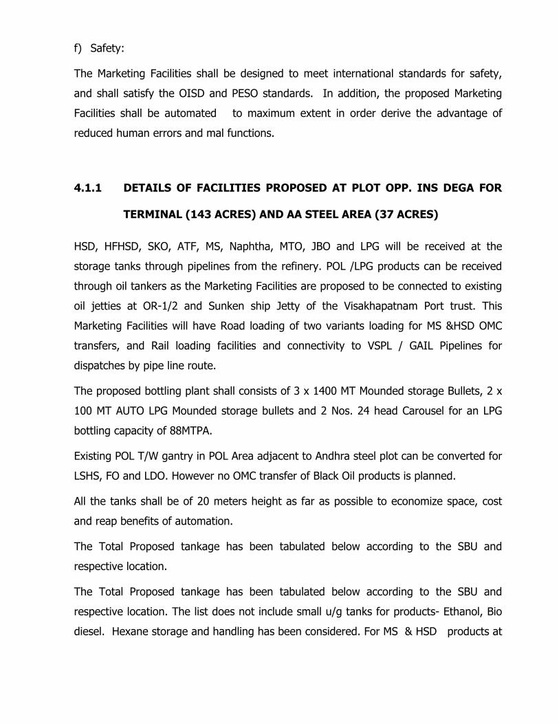
The Total Proposed tankage has been tabulated below according to the SBU and
respective location.
The Total Proposed tankage has been tabulated below according to the SBU and
respective location. The list does not include small u/g tanks for products- Ethanol, Bio
diesel. Hexane storage and handling has been considered. For MS & HSD products at
least one swing tank will be provided with one down bottom to change between
different Euro grade.
SL NO DESCRIPTION
NO OF TANKS
CAPACITY KL
TOTAL CAPACITY LOCATION
1 BITUMEN 2 5000 10,000 ANDHRA STEEL 2 BITUMEN 2 2000 4,000 ANDHRA STEEL 3 BITUMEN 2 800 1600 ANDHRA STEEL
4 FO CST 380/180, LV-FO, LDO & FO SWING TANK 2 5,000 10,000 ANDHRA STEEL
5 FO CST 380/180, 2 5,000 10,000 ANDHRA STEEL 6 F0 380 2 10,000 20,000 ANDHRA STEEL 7 F0 180 2 5,000 10,000 ANDHRA STEEL 8 FO BLEND / HF HSD 2 4000 8,000 ANDHRA STEEL 9 LDO 1 3000 3,000 ANDHRA STEEL
10 LDO 1 4000 4,000 ANDHRA STEEL 11 LSHS 2 3000 6,000 ANDHRA STEEL 12 CRMB/PMB 4 50 200 ANDHRA STEEL 13 LUBE OIL PEDESTAL 2 40 80 ANDHRA STEEL 14 WATER TANKS 2 2200 4400 ANDHRA STEEL
28 91,280
SL NO DESCRIPTION
NO OF TANKS
CAPACITY KL
TOTAL CAPACITY LOCATION
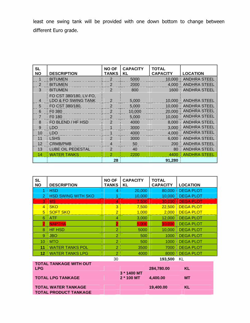
1 HSD 4 20,000 80,000 DEGA PLOT 2 HSD SWING WITH SKO 1 10,000 10,000 DEGA PLOT 3 MS 4 7,500 30,000 DEGA PLOT 4 SKO 3 7,500 22,500 DEGA PLOT 5 SOFT SKO 2 1,000 2,000 DEGA PLOT 6 ATF 4 3,000 12,000 DEGA PLOT
7 NAPTHA 2 5,000 10,000 DEGA PLOT 8 HF HSD 2 5000 10,000 DEGA PLOT
9 JBO 2 500 1000 DEGA PLOT
10 MTO 2 500 1000 DEGA PLOT
11 WATER TANKS POL 2 3500 7000 DEGA PLOT
12 WATER TANKS LPG 2 4000 8000 DEGA PLOT 30 193,500 KL TOTAL TANKAGE WITH OUT LPG
284,780.00 KL
TOTAL LPG TANKAGE 3 * 1400 MT 2 * 100 MT
4,400.00 MT
TOTAL WATER TANKAGE 19,400.00 KL
TOTAL PRODUCT TANKAGE
EXCLUDING LPG AND WATER
265,380.00 KL
TOTAL TANKAGE/STORAGE CAPACITY 2,89,180.00 KL
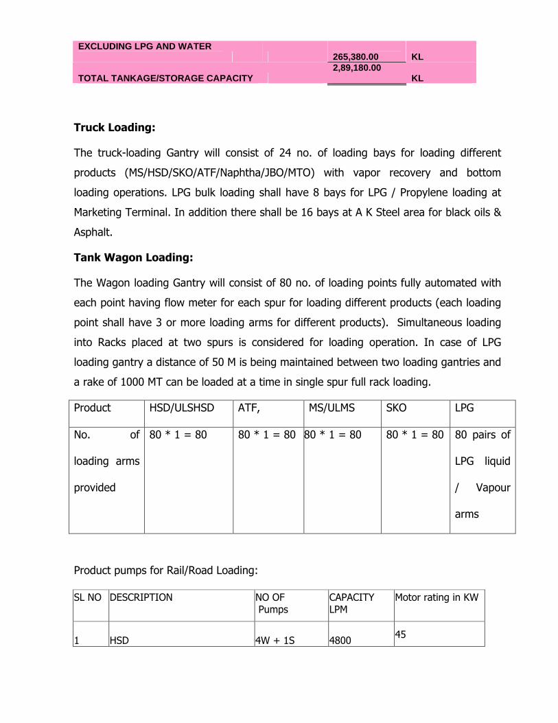
Truck Loading:
The truck-loading Gantry will consist of 24 no. of loading bays for loading different
products (MS/HSD/SKO/ATF/Naphtha/JBO/MTO) with vapor recovery and bottom
loading operations. LPG bulk loading shall have 8 bays for LPG / Propylene loading at
Marketing Terminal. In addition there shall be 16 bays at A K Steel area for black oils &
Asphalt.
Tank Wagon Loading:
The Wagon loading Gantry will consist of 80 no. of loading points fully automated with
each point having flow meter for each spur for loading different products (each loading
point shall have 3 or more loading arms for different products). Simultaneous loading
into Racks placed at two spurs is considered for loading operation. In case of LPG
loading gantry a distance of 50 M is being maintained between two loading gantries and
a rake of 1000 MT can be loaded at a time in single spur full rack loading.
Product HSD/ULSHSD ATF, MS/ULMS SKO LPG
No. of
loading arms
provided
80 * 1 = 80 80 * 1 = 80 80 * 1 = 80 80 * 1 = 80 80 pairs of
LPG liquid
/ Vapour
arms
Product pumps for Rail/Road Loading:
SL NO DESCRIPTION NO OF Pumps
CAPACITY LPM
Motor rating in KW
1 HSD 4W + 1S 4800 45
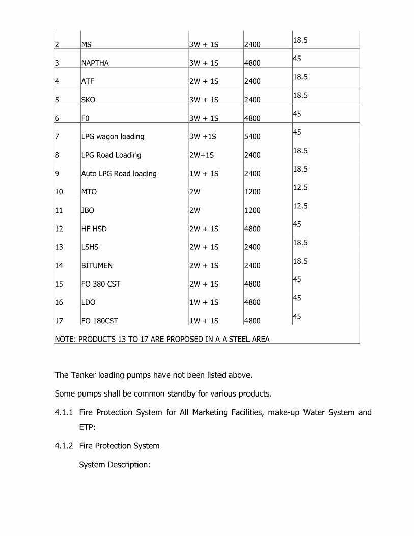
2 MS 3W + 1S 2400 18.5
3 NAPTHA 3W + 1S 4800 45
4 ATF 2W + 1S 2400 18.5
5 SKO 3W + 1S 2400 18.5
6 F0 3W + 1S 4800 45
7 LPG wagon loading 3W +1S 5400 45
8 LPG Road Loading 2W+1S 2400 18.5
9 Auto LPG Road loading 1W + 1S 2400 18.5
10 MTO 2W 1200 12.5
11 JBO 2W 1200 12.5
12 HF HSD 2W + 1S 4800 45
13 LSHS 2W + 1S 2400 18.5
14 BITUMEN 2W + 1S 2400 18.5
15 FO 380 CST 2W + 1S 4800 45
16 LDO 1W + 1S 4800 45
17 FO 180CST 1W + 1S 4800 45
NOTE: PRODUCTS 13 TO 17 ARE PROPOSED IN A A STEEL AREA
The Tanker loading pumps have not been listed above.
Some pumps shall be common standby for various products.
4.1.1 Fire Protection System for All Marketing Facilities, make-up Water System and
ETP:
4.1.2 Fire Protection System
System Description:
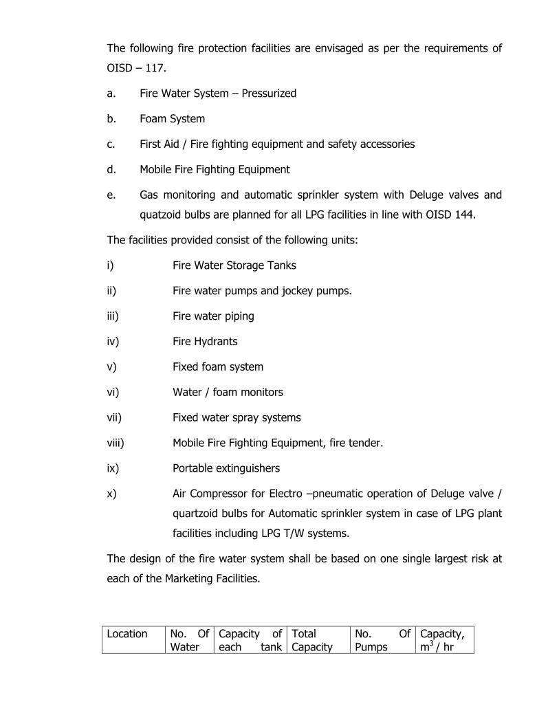
The following fire protection facilities are envisaged as per the requirements of
OISD – 117.
a. Fire Water System – Pressurized
b. Foam System
c. First Aid / Fire fighting equipment and safety accessories
d. Mobile Fire Fighting Equipment
e. Gas monitoring and automatic sprinkler system with Deluge valves and
quatzoid bulbs are planned for all LPG facilities in line with OISD 144.
The facilities provided consist of the following units:
i) Fire Water Storage Tanks
ii) Fire water pumps and jockey pumps.
iii) Fire water piping
iv) Fire Hydrants
v) Fixed foam system
vi) Water / foam monitors
vii) Fixed water spray systems
viii) Mobile Fire Fighting Equipment, fire tender.
ix) Portable extinguishers
x) Air Compressor for Electro –pneumatic operation of Deluge valve /
quartzoid bulbs for Automatic sprinkler system in case of LPG plant
facilities including LPG T/W systems.
The design of the fire water system shall be based on one single largest risk at
each of the Marketing Facilities.
Location No. Of Water
Capacity of each tank
Total Capacity
No. Of Pumps
Capacity, m3 / hr
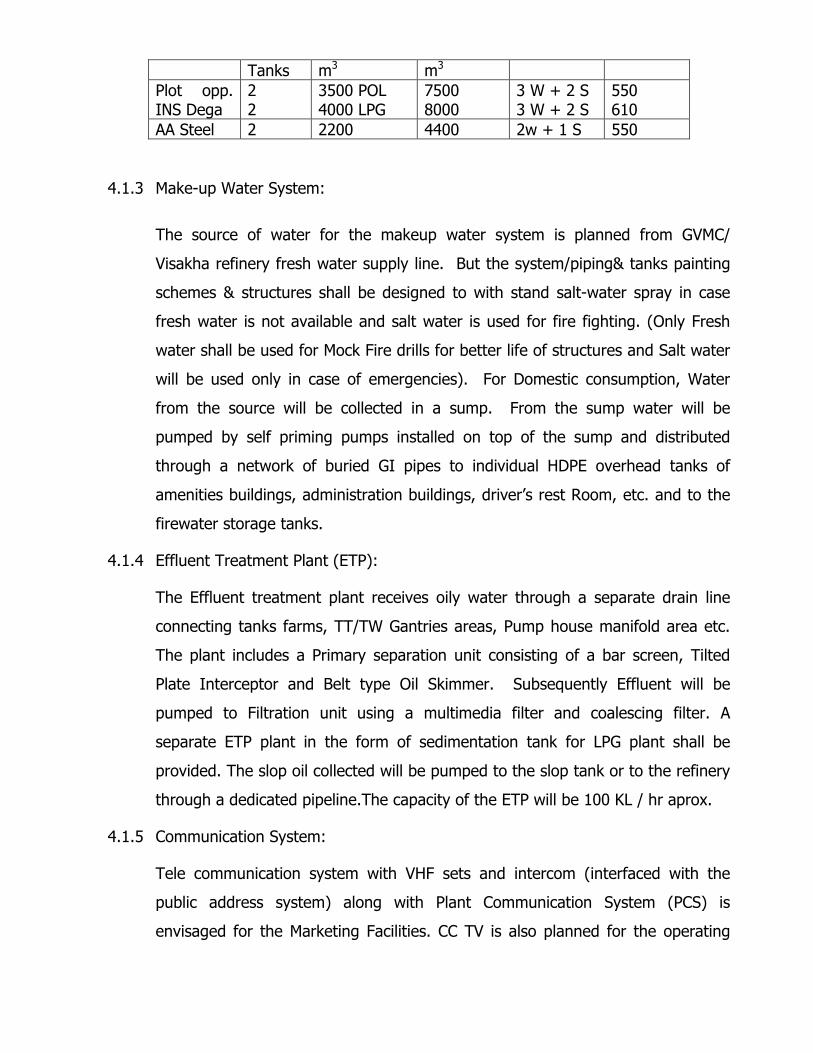
Tanks m3 m3 Plot opp. INS Dega
2 2
3500 POL 4000 LPG
7500 8000
3 W + 2 S 3 W + 2 S
550 610
AA Steel 2 2200 4400 2w + 1 S 550 4.1.3 Make-up Water System:
The source of water for the makeup water system is planned from GVMC/
Visakha refinery fresh water supply line. But the system/piping& tanks painting
schemes & structures shall be designed to with stand salt-water spray in case
fresh water is not available and salt water is used for fire fighting. (Only Fresh
water shall be used for Mock Fire drills for better life of structures and Salt water
will be used only in case of emergencies). For Domestic consumption, Water
from the source will be collected in a sump. From the sump water will be
pumped by self priming pumps installed on top of the sump and distributed
through a network of buried GI pipes to individual HDPE overhead tanks of
amenities buildings, administration buildings, driver’s rest Room, etc. and to the
firewater storage tanks.
4.1.4 Effluent Treatment Plant (ETP):
The Effluent treatment plant receives oily water through a separate drain line
connecting tanks farms, TT/TW Gantries areas, Pump house manifold area etc.
The plant includes a Primary separation unit consisting of a bar screen, Tilted
Plate Interceptor and Belt type Oil Skimmer. Subsequently Effluent will be
pumped to Filtration unit using a multimedia filter and coalescing filter. A
separate ETP plant in the form of sedimentation tank for LPG plant shall be
provided. The slop oil collected will be pumped to the slop tank or to the refinery
through a dedicated pipeline.The capacity of the ETP will be 100 KL / hr aprox.
4.1.5 Communication System:
Tele communication system with VHF sets and intercom (interfaced with the
public address system) along with Plant Communication System (PCS) is
envisaged for the Marketing Facilities. CC TV is also planned for the operating
areas. In addition there shall be provision of regular P&T lines and Broadband
Internet connection.
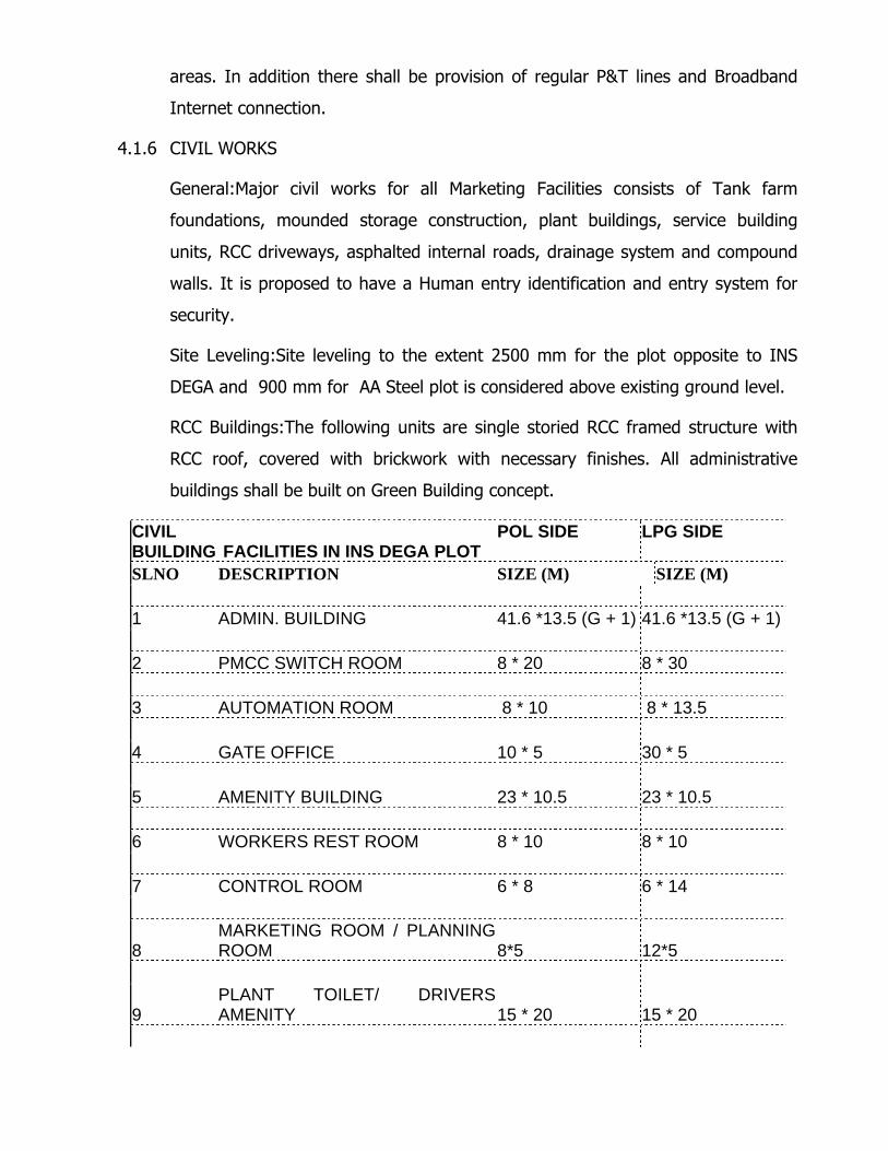
4.1.6 CIVIL WORKS
General:Major civil works for all Marketing Facilities consists of Tank farm
foundations, mounded storage construction, plant buildings, service building
units, RCC driveways, asphalted internal roads, drainage system and compound
walls. It is proposed to have a Human entry identification and entry system for
security.
Site Leveling:Site leveling to the extent 2500 mm for the plot opposite to INS
DEGA and 900 mm for AA Steel plot is considered above existing ground level.
RCC Buildings:The following units are single storied RCC framed structure with
RCC roof, covered with brickwork with necessary finishes. All administrative
buildings shall be built on Green Building concept.
CIVIL BUILDING FACILITIES IN INS DEGA PLOT
POL SIDE LPG SIDE
SLNO DESCRIPTION SIZE (M) SIZE (M) 1 ADMIN. BUILDING 41.6 *13.5 (G + 1) 41.6 *13.5 (G + 1) 2 PMCC SWITCH ROOM 8 * 20 8 * 30 3 AUTOMATION ROOM 8 * 10 8 * 13.5 4 GATE OFFICE 10 * 5 30 * 5 5 AMENITY BUILDING 23 * 10.5 23 * 10.5 6 WORKERS REST ROOM 8 * 10 8 * 10 7 CONTROL ROOM 6 * 8 6 * 14
8 MARKETING ROOM / PLANNING ROOM 8*5 12*5
9 PLANT TOILET/ DRIVERS AMENITY 15 * 20 15 * 20
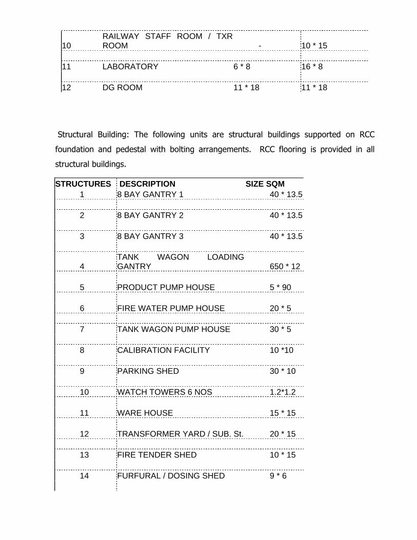
10 RAILWAY STAFF ROOM / TXR ROOM - 10 * 15
11 LABORATORY 6 * 8 16 * 8 12 DG ROOM 11 * 18 11 * 18
Structural Building: The following units are structural buildings supported on RCC
foundation and pedestal with bolting arrangements. RCC flooring is provided in all
structural buildings.
STRUCTURES DESCRIPTION SIZE SQM 1 8 BAY GANTRY 1 40 * 13.5 2 8 BAY GANTRY 2 40 * 13.5 3 8 BAY GANTRY 3 40 * 13.5
4 TANK WAGON LOADING GANTRY 650 * 12
5 PRODUCT PUMP HOUSE 5 * 90 6 FIRE WATER PUMP HOUSE 20 * 5 7 TANK WAGON PUMP HOUSE 30 * 5 8 CALIBRATION FACILITY 10 *10 9 PARKING SHED 30 * 10 10 WATCH TOWERS 6 NOS 1.2*1.2 11 WARE HOUSE 15 * 15 12 TRANSFORMER YARD / SUB. St. 20 * 15 13 FIRE TENDER SHED 10 * 15 14 FURFURAL / DOSING SHED 9 * 6
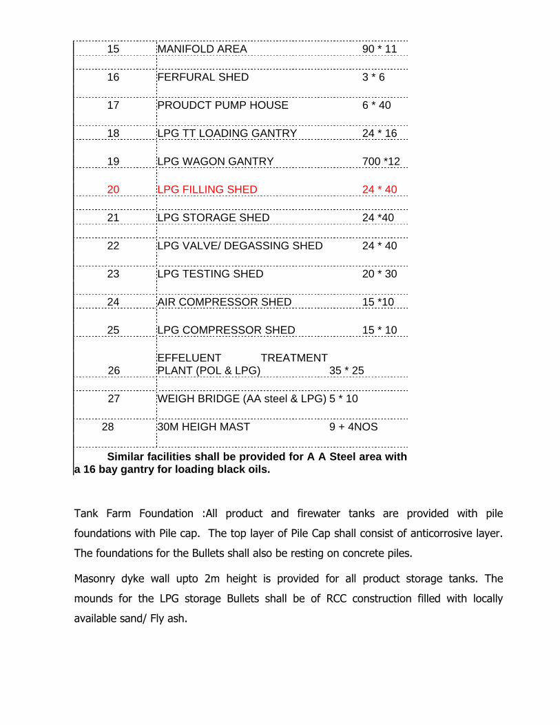
15 MANIFOLD AREA 90 * 11 16 FERFURAL SHED 3 * 6 17 PROUDCT PUMP HOUSE 6 * 40 18 LPG TT LOADING GANTRY 24 * 16 19 LPG WAGON GANTRY 700 *12 20 LPG FILLING SHED 24 * 40 21 LPG STORAGE SHED 24 *40 22 LPG VALVE/ DEGASSING SHED 24 * 40 23 LPG TESTING SHED 20 * 30 24 AIR COMPRESSOR SHED 15 *10 25 LPG COMPRESSOR SHED 15 * 10
26 EFFELUENT TREATMENT PLANT (POL & LPG) 35 * 25
27 WEIGH BRIDGE (AA steel & LPG) 5 * 10 28 30M HEIGH MAST 9 + 4NOS
Similar facilities shall be provided for A A Steel area with
a 16 bay gantry for loading black oils.
Tank Farm Foundation :All product and firewater tanks are provided with pile
foundations with Pile cap. The top layer of Pile Cap shall consist of anticorrosive layer.
The foundations for the Bullets shall also be resting on concrete piles.
Masonry dyke wall upto 2m height is provided for all product storage tanks. The
mounds for the LPG storage Bullets shall be of RCC construction filled with locally
available sand/ Fly ash.
Ground Improvement : Ground Improvement (RCC piles) for Marketing Facilities is
considered based on the existing soil report. Preliminary report indicates that
requirement of ground improvement for all structures including Compound wall.
Road and Drains :Marketing Facilities is proposed with 7.5 m wide internal roads of
bituminous type with water bound macadam. Roads shall have 1m wide berm on either
side. Masonry surface drains are provided on both sides of road.
4.2 OPERATIONAL PHYILOSOPHY
The Major activities performed by Marketing Facilities are as follows:
• Storage facilities for MS, SKO, HSD, ATF, JBO, MTO, NAPTHA and their
variants in composite marketing facility along with LPG/AUTO LPG and
Propylene. The AA Steel area black oil terminal shall handle FO 180 CST, FO
380CST, FO 500CST, LDO, HF HSD, LSHS, Two grades of bulk marine grade
Lube oils and Bitumen with their variants.
• Receipt of product through pipeline
• Road loading / Unloading system for all products except JBO/MTO/Bitumen
• Rail loading and Sick wagon unloading system
• Sump & Slop system.
• Fire water system and make up water system.
• T/W calibration system
Full fledged Marketing Facilities automation system (TAS) is envisaged for above
activities which include:
• Tank Farm /Management System (TFM)
• Truck Data Management Sub System
• Bay Queuing
• Tank Truck Loading
• Station Control System
• Marketing Facilities Security System (TSS)
• Fire Water System Operation
• Make up Water Pump Operation
Automation facilities have been envisaged with a view to ensure safety and ease
the operation of most critical areas of the Marketing Facilities like product
receipt, storage and loading. Service requirements such as scheduling, invoicing,
accounting, sales, stock control, Marketing Facilities security (restricting entry of
unauthorized personnel into licensed area), maintenance etc. to be carried out at
the Marketing Facilities shall be taken care of.
4.2.1 PROCESS DESCRIPTION, DESIGN CRITERIA & OPERATION PHILOSOPHY
A computerized automation system is envisaged for the HPCL Marketing
Facilities.
Activities in Marketing Facilities are as follows:
Receipt of Products through Pipeline
Storage of Products in the Tanks
Dispatch of Products by Road
Dispatch of Products by Rail
Dispatch of Products by Pipeline.
4.2.2 Design Criteria For Road Dispatching Facilities:
Road loading of the products shall be on a volumetric basis using Marketing
Facilities automation system. The products shall be dispensed using PD meters
and loading arms at the respective loading points.
The Design Basis is given below:
• Bottom loading of the truck shall be done. A drop pipe of 3” dia shall be
considered for each truck loading arm.
• Vapour recovery system for TT loading is envisaged.
• Road loading shall be carried out by means of dedicated road loading
pumps.
• Road loading facilities shall be provided with loading arm, PD Meter, Set
Stop Valve and flow cut off protection. Separate flow metering system
and separate loading arm are provided for each product in a loading arm.
• Unloading point for products is provided at each bay for removing the
overfill quantities from the road tankers and products from
stick/contaminated tankers. The unloading material is to be routed into
the individual underground sump tanks under gravity/pump depending on
their location. The sump tank contents shall be pumped back to the
respective product tanks.
• All the MS loading points shall be provided with Ethanol blending facility
and two additive injection facilities.
• The SKO and HSD points shall be provided with 2 additive injection
facilities.
• Mobile Calibration facility shall be provided for PD meters with the aid of a
2000liters capacity proving tank along with all the accessories. Mobile
proving tank shall be provided with leveling instrument etc. required for
calibration along with accessories.
• In case of LPG / Propylene Truck loading, both LPG and vapour loading
arms will be connected at the bottom of truck for filling purpose.
Measurements shall be by coriolis type Mass Flow Meters.
Design Criteria for Rail Dispatching Facilities:
In Plot opp. INS Dega, rail loading of products is proposed. The loading of
wagons will be in automated mode using loading arms and flow meter for white
products and manual loading for black oil T/W. It shall be possible to operate
pumps remotely. In case of LPG, starting of pumps from remote mode is not
planned from Safety point of view. However, stopping of pumps from Control
Room / MCC can be done in Remote mode. Also Interlock of the dispatch pumps
with corresponding product tank level is envisaged. Sick Wagon handling
facilities are also envisaged as part of this facility.
Integrated SCDA system for all LPG pipeline operations and automation of LPG
bottling/filling operations is planned. It is also proposed to have 47.5 /35 kg
cylinder filling operations.
4.2.3 Design Criteria For TFMS Automation:
Tank Farm Management System (TFMS) is a part of Marketing Facilities
Automation System. Each tank shall be provided with Radar type level
transmitter, Multi Element averaging temperature sensor, Water/Product
interface measurement and pressure transmitters for density measurement. The
indication shall be available locally in the tank side display unit and in the TAS in
the control room. In case of LPG storage, Rochester Gauges, Radar gauges &
servo level gauges with Pressure and Temperature Indication and online density
measurement are proposed for LPG tank Farm Management. Underground tanks
shall be provided with Radar type level transmitter. Data of the underground
tank shall be available on the TAS. Volumetric data of each product shall also be
available as a part of tank farm management system.
4.2.4 Design Criteria For TLF Pump Automation:
• Product loading pumps for TLF bay shall be started automatically.
• No of pumps in operation is decided by the demand of the product/no. of
loading bays in operation/Flow rate.
• Incase primary pump fails standby pump shall take over.
• Pumps can be operated in local mode and remote mode.
• Pump Control is achieved through the PLC.
• Operation of pumps is interlocked with the level of product in the tank.
4.2.5 Design Criteria For Fire Water Pump Automation:
• Firewater pumps shall be diesel engine driven.
• Shall be activated by remote manual call points located at various points
in the Marketing Facilities /depot.
• If the pressure developed by one pump drops less than 7 kg/cm2 second
pump shall start automatically.
• The number and capacity of fire water pumps required for each facility
shall be calculated as per relevant OISD standards.
• 50% standby fire water pumps shall be provided as per OISD norms.
• If any operational pumps fails to start or develops defect the standby
pump shall come into operation.
• Firewater pump automation is achieved through PLC.
• It shall be possible to operate the pumps manually either locally or from
control room.
4.2.6 Design Criteria For Make Up Water Pump Automation
• Make up water system shall have make up water pumps.
• The pumps shall start automatically whenever the level in the any of the
two water tanks falls below 15 cm from the max level of the tank.
• Pumps will stop automatically when the level reaches the max. Level.
• This operation is achieved through PLC.
• Necessary alarm logic shall be available in the control room.
• It shall be possible to operate the Pumps manually either locally or from
control room.
4.3 Marketing Facilities at AA Steel area for Black Oils: Facilities proposed at Black Oil
Marketing Facilities are similar to that of above but will have provision for blending
of various grades of FO and variants of Bitumen .New Tank wagon loading facilities
will not be provided but existing POL T/W gantry will be converted to B/O gantry.
Automation for Tank Farm Management, TT loading and Fire Water system is
planned for Facilities at AA steel Area.
4.4 Operating Philosophy of Marketing Facilities at AA Steel area for Black Oils:
• Bunkering activity will be taken up through barge loading of FO,LDO and
HFHSD by pumping at minimum 600kl/hr.
• Packed Bitumen Rake loading will be taken up at VPT/Railway yard.
• HFHSD tank wagon loading will be taken up at INS DEGA and T/T loading at
AA Steel area.
• No OMC transfers for all the products stored .
• Loading of LSHS and Bitumen will be on weight basis .
• Top loading of T/T.
• Tank wagon loading of LSHS / FO 2 variants/LDO will be
5. Expected Benefits as a result of project:
• Creation of Additional space of approximately 60 acres adjacent to Visakh
Refinery by shifting Marketing facilities (POL &LPG), there by enabling VR for
addition of process units required for EURO fuels / meeting their expansion
norms.
• Creation of Marketing Facilities, which is in line with company’s vision of safe and
environment Friendly operations.
• Increased storage capacity to meet the increasing market demand and
also meeting Refinery expansion needs and scope for future tankages.
• Composite Marketing Facilities having TT loading, TW loading and with a
connectivity to existing dispatch pipelines of VSPL and GAIL.
• Facilitate OMC transfer of White oil from marketing installation.
• Utilize Plot opp. INS Dega & Port facilities, which shall facilitate dedicated
oil jetty.
• Flexibility of receiving product through costal moment incase of
crises/exigencies at Visakha Refinery.
• Shall facilitate evacuation of SALPG volumes and will reduce our
dependency on EIPL.
6. Implementation plan:
a) Approach to implementation:
(i) LSTK - a definition:
Outsourcing is the fundamental premise of the concept. It is useful in case of
companies, which do not have construction management as a core competency.
Even in cases where it is equipped to handle construction projects, the
departments may be overloaded and the growing expectations/demands with
regard to time frame and quality of projects today make them look for such
options.
Vendors are asked to submit quotations of overall cost i.e. a single figure for the
entire job. This makes the analysis of bids easier. However, the single most
important requirement for this system is that the entire plan, specifications of the
job to be carried out are clear and frozen. Detailed engineering has to be done
and final decisions have to be taken before tendering. Any change in
decision/technical parameters will affect the bid and makes the system
unworkable.
The work ‘turnkey’ indicates where the contractor not only quotes but also
submits technical inputs such as designs, details, specifications, etc. suitable for
a given job. As such it is more suitable for process-based projects. In recent
times, the word 'turnkey' is made to mean composite contracts where integration
has been the by word: wherein the various jobs of civil, electrical, mechanical,
interiors are all clubbed together under one umbrella contract. This was done to
minimize the delay in finalizing individual contracts and avoid project delays due
to lack of synchronization among the different jobs.
LSTK contracts are advantageous in following areas:
(a) Detailed engineering and design .
(b) Tendering for procurement of various materials and services.
(c) Integrated construction program vis-à-vis various agencies for civil
works, mechanical works, electrical works which results in difficulties of
coordination and delays the overall completion of the project.
Cost of LSTK:
It is a reasonable apprehension that by clubbing together various procurement,
services and looking for a major EPC Contractor to satisfy all the requirements,
which is akin to placing all the eggs in one basket, the cost of construction may
go high. One has to analyze the cost vs. benefit of the same to really appreciate
whether LSTK is worth the money.
Other implications include freezing of plans and parameters of project before
tendering which is not the case applicable to dynamic scenario obtaining in our
projects. Especially in oil industry projects where innovation and improvement of
plans, specs is a vital characteristic. The decision making style is completely
unsuitable for such handling.
However the following separate LSTK tenders may be required to be floated as
the activities are independent and require entirely different skill levels for
executions.
� Entire Marketing Facilities
� Marketing Facilities Automation
� Tanker Discharge Pipelines
� Railway siding
(ii) Proposed Alternative:
LSTK plus Conventional: Certain high value procurement items, if floated
separately, can be procured at very competitive prices. Moreover, certain activities
like construction of compound wall, site office etc. can be taken up immediately
which will save construction time.
Basis above reasoning, following tenders and LSTK packages can be formulated:

� Tender for procurement of Steel Plates / BQ (Boiler Quality) Plates
� Tender for procurement of 3 layer PE coated pipes
� Tender for Pumps
� Tender for valves.
� Tender for Loading Arms
� Tender for Site development
� Tender for compound wall and site office
� Tender for electrical equipments (DG Sets and transformers)
� Tenders for Marketing Facilities excluding above supplies
1. Building structures and roads
2. Tankages (POL & LPG separately)
3. Pipeline jobs.
4. Electrical jobs including HT lines.
� LSTK for Marketing Facilities Automation
� LSTK for Tanker discharge lines
� LSTK for Railway siding
Above Option II has following distinct advantages:
� Since the packages being predominantly LSTK in nature, fast tracking of the
project can still be achieved.
� As high value items are being procured directly by us through regular tendering
process, substantial cost savings can be achieved. Moreover this will also ensure
availability of such long lead Items for LSTK Contractor resulting in reduction in
construction time.
� If certain high value procurement items are excluded from the scope of LSTK
contractor, the overheads, which LSTK contractor would have loaded on his
quoted prices, can be avoided.
� LSTK contract as a whole being works contract, WCT would be applicable on whole
contract including supplies portion. Contractor would therefore load prices of
supplies to this effect. This can be avoided if these high value procurement items
are removed from his scope.
In view of the above advantages, it is proposed that the Project be implemented
on LSTK plus conventional basis. However separate tenders are being planned
for Black oil terminal at A K Steel area and for White Oil terminal & LPG Plant at
plot op. INS Dega as it is anticipated that these two sites may be acquired and
approvals are expected to be obtained at different time frames. Thus this would
enable these jobs to be carried out independently.
Oil storage Marketing Facilities are simple projects of mass scale in which we are
having adequate experience and expertise. However, for better and latest design
technology, quality and faster preparation of details, tender, we need a project
consultant. This will be applicable also in proposed LSTK plus conventional option.
Hence in addition to the above listed tenders we are required to float a tender for
consultancy in line with our LSTK plus conventional option.
b) Organizational resources required:
The Project team consisting of a Ch. Manager and 1 Sr. Managers for POL and 1
Manager for LPG are already stationed at Visakhapatnam for the project. There is
a need for following organizational resource.
� Purchase Department: Purchase Department with one officer and one clerical
assistant is recommended to float the various Tenders as listed above. It shall be
required to float Tenders of Miscellanies nature to cater to the project expenses.
Like office services, postal services, transport services, miscellanies jobs at site.
� Finance Department: Looking into the nature of the project and requirement of
completing the project with stiff schedule it shall be advantages to have a finance
department with one officer and one clerical assistant to ensure timely payments
to the parties and also help financial closure within a short time.
The above staff for Purchase and Finance shall be over and above the already
placed manpower at Marketing project office at Chennai.
Since LSTK contracts involve procurement and erection, healthy cash flow is very
essential for smooth execution of the project. In order to create healthy cash
flow which will enable speedy construction the new General Terms & Conditions
with faster payment terms shall be implemented.
• Marketing Contracts Committee (MCC) at Chennai: MCC has been formed
consisting of Finance, Purchase and User department at Chennai in order to
expedite the placement of Purchase orders of both Ennore and Visakha resitement
projects.
c) Manpower
Manpower requirements for the execution of the project:
1. Ch.ProjectManager
2. 2 Sr Managers (1 for POL Facilities and 1 for LPG facilities)
3. 3 - A/B/C Engineers: 1fortankages
1forcivilstructures
1 for mechanical structures
d) Plant/equipment/materials : As the proposed Marketing Facilities is a grass root
Marketing Facilities the entire plant, equipment and material shall be in the scope
of LSTK contracts or shall be procured by tendering. However, for pre-project
activities and liaising purpose it is proposed to have a Project office at VVSPL.
e) Implementation schedule: The detailed Implementation schedule has been
presented in the project office format enclosed. The salient features of the
implementation schedule are as follows:
� The Pre-Project activities shall involve floating of tenders and obtaining the
following statutory approvals and surveys.
2. Approval from PESO (CCOE)
3. Liaison with CEC/VR for MOE & F Approval / CRZ approval
a. EIA, Risk Analysis and DMP
b. Public Hearing
c. NOC from AP PCB
d. Presentation to MOE & F Expert committee meeting
e. Approval from MOE & F
This activity is being taken up by Central Engineering Cell (CEC) as part of total
refinery expansion/modernization program.
4. Single window clearances consisting of
a. DMs NOC.
b. Approval from State Pollution Control Board
c. Approval from Inspector of Factories
5. Construction approval from VPT/ Town planning
6. Permissions / ROU acquisition for laying of Jetty pipelines
7. Crossing approvals viz., Rail / Road etc.
Engineering Surveys:
1. Topography survey
2. Soil Investigation
3. Detailed Route survey for Jetty lines
4. Cadastral Survey.
The physical project activities shall start after obtaining Management approval ,
receipt of clearance from MOE & F and statutory approvals which ever is later.
7) Project Estimates:
The tabletop project estimates has been worked out and have been enclosed as
Attachment II. The total cost is estimated to be Rs. 575 Crores.
8) Time Frame:
The project is targeted to be expected to be mechanically completed within 18 to
24 months (Detailed Feasibility Study is being undertaken to finalize realistic
stretched target time) from the date of handing over the land/statutory MOEF
approval which ever is later.
Keeping in view the complexity of the project and in order to fine tune and
optimize the scope, time frame, identify project finance and cost detailed
feasibility report and financial appraisal are also being carried out