school building authority of west virginia building...
TRANSCRIPT
365
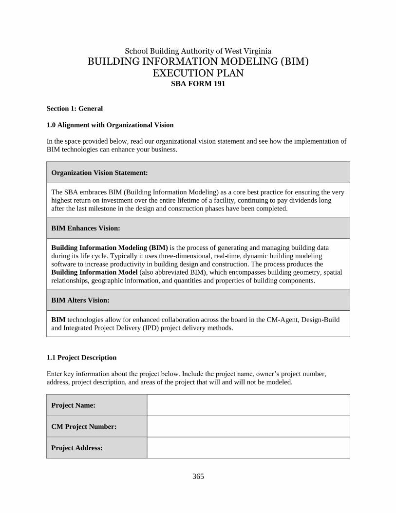
School Building Authority of West Virginia
BUILDING INFORMATION MODELING (BIM) EXECUTION PLAN
SBA FORM 191
Section 1: General
1.0 Alignment with Organizational Vision
In the space provided below, read our organizational vision statement and see how the implementation of
BIM technologies can enhance your business.
Organization Vision Statement:
The SBA embraces BIM (Building Information Modeling) as a core best practice for ensuring the very
highest return on investment over the entire lifetime of a facility, continuing to pay dividends long
after the last milestone in the design and construction phases have been completed.
BIM Enhances Vision:
Building Information Modeling (BIM) is the process of generating and managing building data
during its life cycle. Typically it uses three-dimensional, real-time, dynamic building modeling
software to increase productivity in building design and construction. The process produces the
Building Information Model (also abbreviated BIM), which encompasses building geometry, spatial
relationships, geographic information, and quantities and properties of building components.
BIM Alters Vision:
BIM technologies allow for enhanced collaboration across the board in the CM-Agent, Design-Build
and Integrated Project Delivery (IPD) project delivery methods.
1.1 Project Description
Enter key information about the project below. Include the project name, owner’s project number,
address, project description, and areas of the project that will and will not be modeled.
Project Name:
CM Project Number:
Project Address:

366
Project Description:
Areas Modeled:
Purpose of BIM
Implementation:
The purpose for BIM Implementation on this project is to allow for
enhanced coordination of the project design through construction
operations to achieve a more efficient process. The BIM process
serves to allow for visualization of design and construction
elements, increase communication between the design team and the
construction team, more accurate coordination of installed systems
and components, reduction in errors and oversights normally found
in field conditions and mis-coordination, and a higher quality
installation of product and deliverable as-builts for record for the
Building Owner.
1.2 Project Goals and Objectives
Below, are some objectives for using BIM and collaborative project management technology and
processes on this project. Also note how you will measure the achievement of each objective, and its
target time frame.
Project Goal: Objective: Achieved If: Projected Timeframe:
Successful
coordination of all
building systems
using Autodesk
Navisworks
Manage Software
during the
Construction
Coordination
Process
Require MEP Primes/Subs to
produce 3D models for
coordination process,
streamline coordination from
traditional paper drawing
method
MEP systems are
effectively
coordinated when
installed, systems
are installed on time
per the project
schedule
Per the Project Schedule
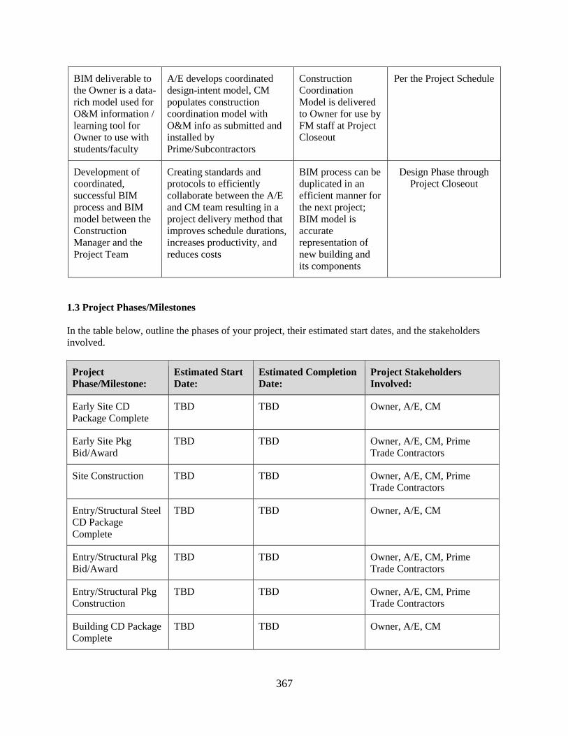
367
BIM deliverable to
the Owner is a data-
rich model used for
O&M information /
learning tool for
Owner to use with
students/faculty
A/E develops coordinated
design-intent model, CM
populates construction
coordination model with
O&M info as submitted and
installed by
Prime/Subcontractors
Construction
Coordination
Model is delivered
to Owner for use by
FM staff at Project
Closeout
Per the Project Schedule
Development of
coordinated,
successful BIM
process and BIM
model between the
Construction
Manager and the
Project Team
Creating standards and
protocols to efficiently
collaborate between the A/E
and CM team resulting in a
project delivery method that
improves schedule durations,
increases productivity, and
reduces costs
BIM process can be
duplicated in an
efficient manner for
the next project;
BIM model is
accurate
representation of
new building and
its components
Design Phase through
Project Closeout
1.3 Project Phases/Milestones
In the table below, outline the phases of your project, their estimated start dates, and the stakeholders
involved.
Project
Phase/Milestone:
Estimated Start
Date:
Estimated Completion
Date:
Project Stakeholders
Involved:
Early Site CD
Package Complete
TBD TBD Owner, A/E, CM
Early Site Pkg
Bid/Award
TBD TBD Owner, A/E, CM, Prime
Trade Contractors
Site Construction TBD TBD Owner, A/E, CM, Prime
Trade Contractors
Entry/Structural Steel
CD Package
Complete
TBD TBD Owner, A/E, CM
Entry/Structural Pkg
Bid/Award
TBD TBD Owner, A/E, CM, Prime
Trade Contractors
Entry/Structural Pkg
Construction
TBD TBD Owner, A/E, CM, Prime
Trade Contractors
Building CD Package
Complete
TBD TBD Owner, A/E, CM

368
Building Pkg
Bid/Award
TBD TBD Owner, A/E, CM, Prime
Trade Contractors
Building Package
Construction
TBD TBD Owner, A/E, CM, Prime
Trade Contractors
Punchlist TBD TBD Owner, A/E, CM, Prime
Trade Contractors
Substantial
Completion
TBD TBD Owner, A/E, CM, Prime
Trade Contractors
Punchlist, FFE and
Closeout
TBD TBD Owner, A/E, CM, Prime
Trade Contractors
Final Completion TBD TBD Owner, A/E, CM, Prime
Trade Contractors
*(all dates subject to change
based on Project Schedule
revisions as determined by
Project Team)*
Section 2: Design/Construction Documents
2.0 Model Managers/Collaboration Team
List the major members for your project below.
Contact
Name: Role/Title: Company: Email: Phone:
Project Architect
Mechanical Eng.
Electrical Eng.
Structural Eng.
Fire Protection
Civil Eng.
369
Construction
Manager
Prime Contractor
Prime Contractor
Prime Contractor
Construction
Manager
Coordination
Manager
Mech. Contractor
Model Manager
2.1 Planned Models / Reviewing
In the table below, outline the models that will be created for the project. List the model name, model
content, project phase at which the model will be delivered, the model’s authoring company, and the
model authoring tool to be used. For models that will not be used or created in your project, just leave the
row blank; add rows for any model types you anticipate a need for that are not already listed.
Model Name: Model Content: Project
Phase: Reviewing Company:
Authoring
Tool:
Design-Intent
Coordination
Models
Architectural, Civil,
Structural, and MEP
components of main
building and other
associated structures (as
necessary for proper
construction
coordination and
assembly of building
systems/components).
(as specified under AIA
E203 LOD 100
Design
Development
and
Construction
Documents
Architect,
Civil Engineer,
Structural Engineer,
MEP Engineer,
Other Consultants as
needed
Autodesk®
Revit®
software,
other
programs to
be
submitted
for approval
to A/E and
CM.
(Current
Versions)
370
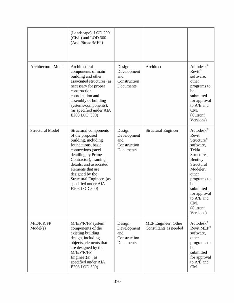
(Landscape), LOD 200
(Civil) and LOD 300
(Arch/Struct/MEP)
Architectural Model Architectural
components of main
building and other
associated structures (as
necessary for proper
construction
coordination and
assembly of building
systems/components).
(as specified under AIA
E203 LOD 300)
Design
Development
and
Construction
Documents
Architect Autodesk®
Revit®
software,
other
programs to
be
submitted
for approval
to A/E and
CM.
(Current
Versions)
Structural Model Structural components
of the proposed
building, including
foundations, basic
connections (steel
detailing by Prime
Contractor), framing
details, and associated
elements that are
designed by the
Structural Engineer. (as
specified under AIA
E203 LOD 300)
Design
Development
and
Construction
Documents
Structural Engineer Autodesk®
Revit
Structure®
software,
Tekla
Structures,
Bentley
Structural
Modeler,
other
programs to
be
submitted
for approval
to A/E and
CM.
(Current
Versions)
M/E/P/R/FP
Model(s)
M/E/P/R/FP system
components of the
existing building
design, including
objects, elements that
are designed by the
M/E/P/R/FP
Engineer(s). (as
specified under AIA
E203 LOD 300)
Design
Development
and
Construction
Documents
MEP Engineer, Other
Consultants as needed
Autodesk®
Revit MEP®
software,
other
programs to
be
submitted
for approval
to A/E and
CM.

371
(Current
Versions)
Overall
Construction
Coordination
Model(s)
Coordinated Design-
Intent Model through
Clash Detection
sessions, includes Site
Logistics and phasing
(optional), 4-D
scheduling (optional);
model will be populated
with O&M information
as a deliverable to
Owner.
(as specified under AIA
E203 LOD 400)
Construction
Documents
and ongoing
through
Construction
Phase
A/E to deliver Design-
Intent Models at
outlined LODs to CM.
CM becomes model
owner during
construction
coordination process.
Prime Contractors model their respective
scopes of work in 3D
and produce
coordination models.
Autodesk
Revit,
Autodesk
Navisworks,
Microsoft
Project,
Primavera
P6, other
programs to
be
submitted
for approval
to A/E and
CM.
(Current
Versions)
Prime/Subcontractor
Coordination
Model(s)
All specific components
of the
Prime/Subcontractor’s scope of work to
interface with the
Construction
Coordination Model,
models are developed
by Primes/Subs and
coordinated by the
Lead Contractor
(HVAC) and CM.
(as specified under AIA
E203 LOD 400).
Primes/Subs required
to submit models are:
Structural Steel,
HVAC, Electrical,
Plumbing, Fire
Protection,
Geothermal
(coordinate paths and
locations in 3D),
Technology
(coordinate paths and
locations in 3D).
Construction
Documents
and
Contractor
Coordination
Meetings
Models created and
presented by each
Prime/Subcontractor,
models managed by
Lead Contractor
(HVAC) and CM;
A/E participates as
needed during
coordination.
HVAC Contractor is
Lead Prime for
Navisworks Manage
3D coordination.
Autodesk
Civil 3D,
Autodesk
Revit
Structure,
Autodesk
Revit MEP,
Autodesk
Navisworks,
other
programs to
be
submitted
for approval
to A/E and
CM
372
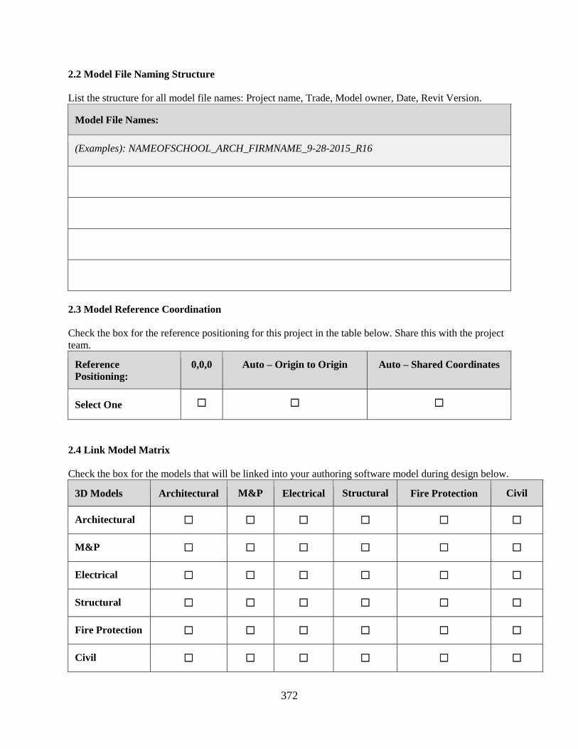
2.2 Model File Naming Structure
List the structure for all model file names: Project name, Trade, Model owner, Date, Revit Version.
Model File Names:
(Examples): NAMEOFSCHOOL_ARCH_FIRMNAME_9-28-2015_R16
2.3 Model Reference Coordination
Check the box for the reference positioning for this project in the table below. Share this with the project
team.
Reference
Positioning:
0,0,0 Auto – Origin to Origin Auto – Shared Coordinates
Select One ☐ ☐ ☐
2.4 Link Model Matrix
Check the box for the models that will be linked into your authoring software model during design below.
3D Models Architectural M&P Electrical Structural Fire Protection Civil
Architectural ☐ ☐ ☐ ☐ ☐ ☐
M&P ☐ ☐ ☐ ☐ ☐ ☐
Electrical ☐ ☐ ☐ ☐ ☐ ☐
Structural ☐ ☐ ☐ ☐ ☐ ☐
Fire Protection ☐ ☐ ☐ ☐ ☐ ☐
Civil ☐ ☐ ☐ ☐ ☐ ☐
373
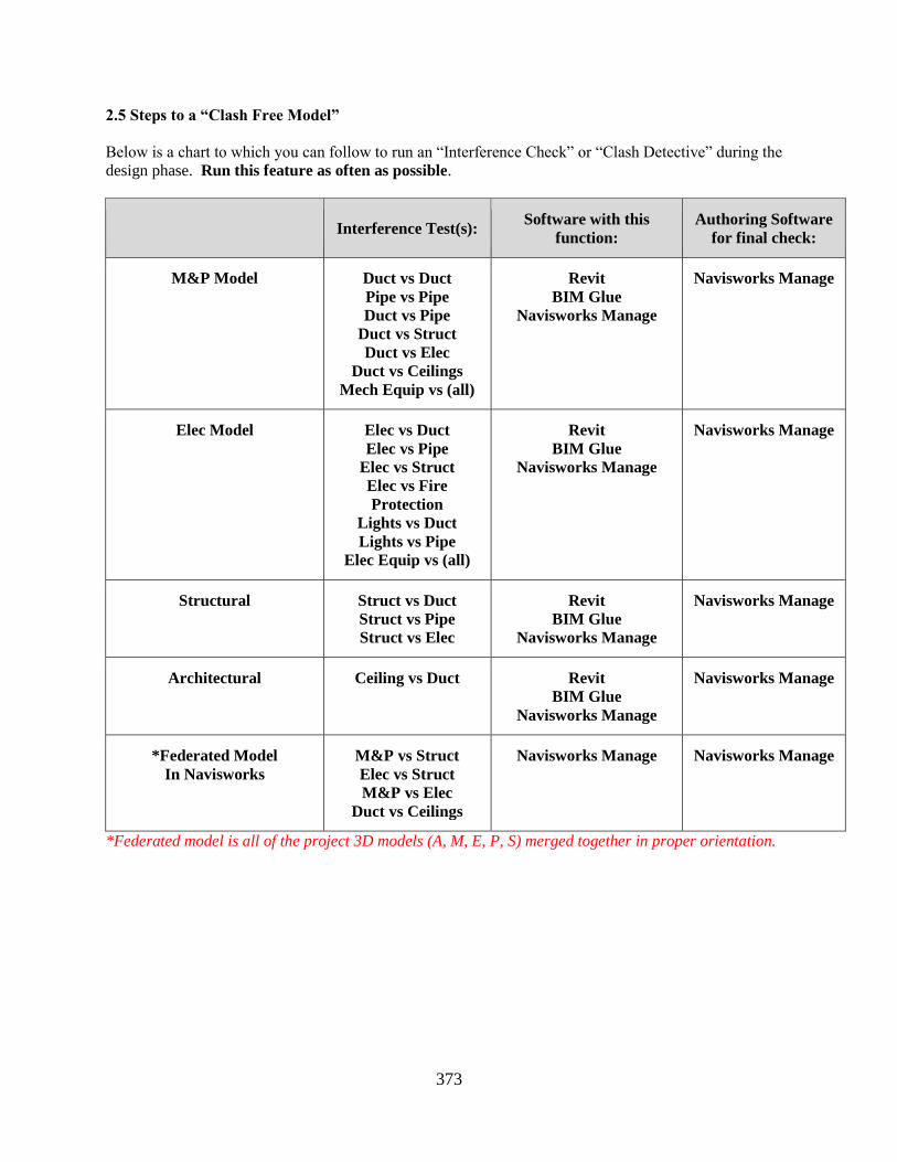
2.5 Steps to a “Clash Free Model”
Below is a chart to which you can follow to run an “Interference Check” or “Clash Detective” during the
design phase. Run this feature as often as possible.
Interference Test(s): Software with this
function:
Authoring Software
for final check:
M&P Model Duct vs Duct
Pipe vs Pipe
Duct vs Pipe
Duct vs Struct
Duct vs Elec
Duct vs Ceilings
Mech Equip vs (all)
Revit
BIM Glue
Navisworks Manage
Navisworks Manage
Elec Model Elec vs Duct
Elec vs Pipe
Elec vs Struct
Elec vs Fire
Protection
Lights vs Duct
Lights vs Pipe
Elec Equip vs (all)
Revit
BIM Glue
Navisworks Manage
Navisworks Manage
Structural Struct vs Duct
Struct vs Pipe
Struct vs Elec
Revit
BIM Glue
Navisworks Manage
Navisworks Manage
Architectural Ceiling vs Duct Revit
BIM Glue
Navisworks Manage
Navisworks Manage
*Federated Model
In Navisworks
M&P vs Struct
Elec vs Struct
M&P vs Elec
Duct vs Ceilings
Navisworks Manage Navisworks Manage
*Federated model is all of the project 3D models (A, M, E, P, S) merged together in proper orientation.
374
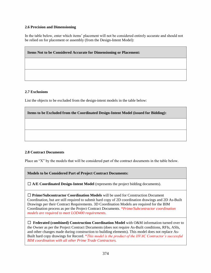
2.6 Precision and Dimensioning
In the table below, enter which items’ placement will not be considered entirely accurate and should not
be relied on for placement or assembly (from the Design-Intent Model):
Items Not to be Considered Accurate for Dimensioning or Placement:
2.7 Exclusions
List the objects to be excluded from the design-intent models in the table below:
Items to be Excluded from the Coordinated Design-Intent Model (issued for Bidding):
2.8 Contract Documents
Place an “X” by the models that will be considered part of the contract documents in the table below.
Models to be Considered Part of Project Contract Documents:
☐ A/E Coordinated Design-Intent Model (represents the project bidding documents).
☐ Prime/Subcontractor Coordination Models will be used for Construction Document
Coordination, but are still required to submit hard copy of 2D coordination drawings and 2D As-Built
Drawings per their Contract Requirements. 3D Coordination Models are required for the BIM
Coordination process as per the Project Contract Documents. *Prime/Subcontractor coordination
models are required to meet LOD400 requirements.
☐ Federated (combined) Construction Coordination Model with O&M information turned over to
the Owner as per the Project Contract Documents (does not require As-Built conditions, RFIs, ASIs,
and other changes made during construction to building elements). This model does not replace As-
Built hard copy drawings for Record. *This model is the product of the HVAC Contractor’s successful
BIM coordination with all other Prime Trade Contractors.
375
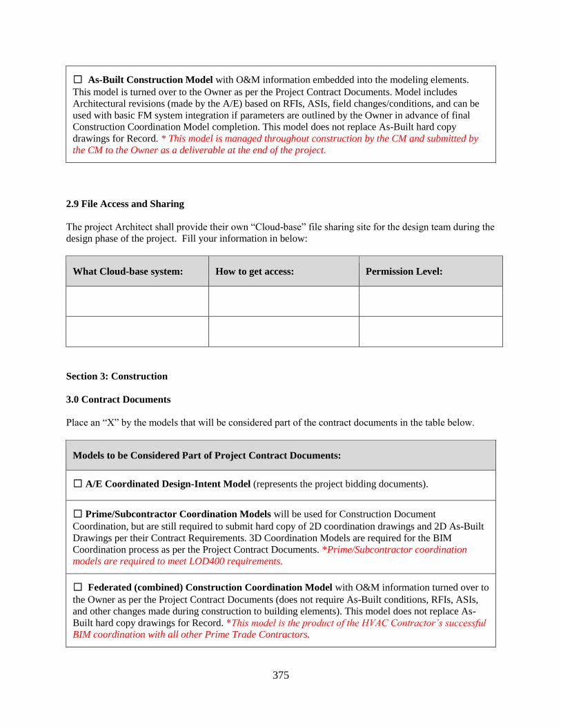
☐ As-Built Construction Model with O&M information embedded into the modeling elements.
This model is turned over to the Owner as per the Project Contract Documents. Model includes
Architectural revisions (made by the A/E) based on RFIs, ASIs, field changes/conditions, and can be
used with basic FM system integration if parameters are outlined by the Owner in advance of final
Construction Coordination Model completion. This model does not replace As-Built hard copy
drawings for Record. * This model is managed throughout construction by the CM and submitted by
the CM to the Owner as a deliverable at the end of the project.
2.9 File Access and Sharing
The project Architect shall provide their own “Cloud-base” file sharing site for the design team during the
design phase of the project. Fill your information in below:
What Cloud-base system: How to get access: Permission Level:
Section 3: Construction
3.0 Contract Documents
Place an “X” by the models that will be considered part of the contract documents in the table below.
Models to be Considered Part of Project Contract Documents:
☐ A/E Coordinated Design-Intent Model (represents the project bidding documents).
☐ Prime/Subcontractor Coordination Models will be used for Construction Document
Coordination, but are still required to submit hard copy of 2D coordination drawings and 2D As-Built
Drawings per their Contract Requirements. 3D Coordination Models are required for the BIM
Coordination process as per the Project Contract Documents. *Prime/Subcontractor coordination
models are required to meet LOD400 requirements.
☐ Federated (combined) Construction Coordination Model with O&M information turned over to
the Owner as per the Project Contract Documents (does not require As-Built conditions, RFIs, ASIs,
and other changes made during construction to building elements). This model does not replace As-
Built hard copy drawings for Record. *This model is the product of the HVAC Contractor’s successful
BIM coordination with all other Prime Trade Contractors.
376
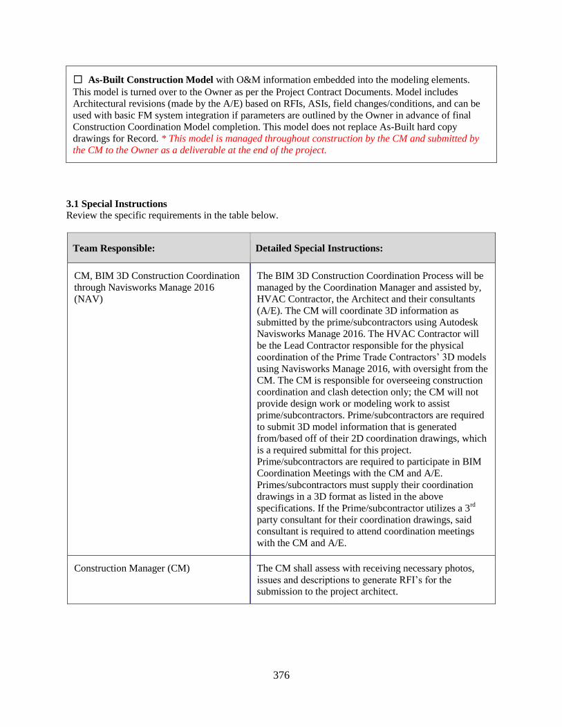
☐ As-Built Construction Model with O&M information embedded into the modeling elements.
This model is turned over to the Owner as per the Project Contract Documents. Model includes
Architectural revisions (made by the A/E) based on RFIs, ASIs, field changes/conditions, and can be
used with basic FM system integration if parameters are outlined by the Owner in advance of final
Construction Coordination Model completion. This model does not replace As-Built hard copy
drawings for Record. * This model is managed throughout construction by the CM and submitted by
the CM to the Owner as a deliverable at the end of the project.
3.1 Special Instructions
Review the specific requirements in the table below.
Team Responsible: Detailed Special Instructions:
CM, BIM 3D Construction Coordination
through Navisworks Manage 2016
(NAV)
The BIM 3D Construction Coordination Process will be
managed by the Coordination Manager and assisted by,
HVAC Contractor, the Architect and their consultants
(A/E). The CM will coordinate 3D information as
submitted by the prime/subcontractors using Autodesk
Navisworks Manage 2016. The HVAC Contractor will
be the Lead Contractor responsible for the physical
coordination of the Prime Trade Contractors’ 3D models
using Navisworks Manage 2016, with oversight from the
CM. The CM is responsible for overseeing construction
coordination and clash detection only; the CM will not
provide design work or modeling work to assist
prime/subcontractors. Prime/subcontractors are required
to submit 3D model information that is generated
from/based off of their 2D coordination drawings, which
is a required submittal for this project.
Prime/subcontractors are required to participate in BIM
Coordination Meetings with the CM and A/E.
Primes/subcontractors must supply their coordination
drawings in a 3D format as listed in the above
specifications. If the Prime/subcontractor utilizes a 3rd
party consultant for their coordination drawings, said
consultant is required to attend coordination meetings
with the CM and A/E.
Construction Manager (CM) The CM shall assess with receiving necessary photos,
issues and descriptions to generate RFI’s for the
submission to the project architect.
377
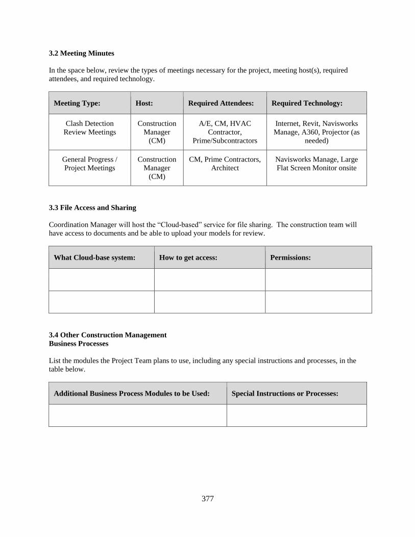
3.2 Meeting Minutes
In the space below, review the types of meetings necessary for the project, meeting host(s), required
attendees, and required technology.
Meeting Type: Host: Required Attendees: Required Technology:
Clash Detection
Review Meetings
Construction
Manager
(CM)
A/E, CM, HVAC
Contractor,
Prime/Subcontractors
Internet, Revit, Navisworks
Manage, A360, Projector (as
needed)
General Progress /
Project Meetings
Construction
Manager
(CM)
CM, Prime Contractors,
Architect
Navisworks Manage, Large
Flat Screen Monitor onsite
3.3 File Access and Sharing
Coordination Manager will host the “Cloud-based” service for file sharing. The construction team will
have access to documents and be able to upload your models for review.
What Cloud-base system: How to get access: Permissions:
3.4 Other Construction Management
Business Processes
List the modules the Project Team plans to use, including any special instructions and processes, in the
table below.
Additional Business Process Modules to be Used: Special Instructions or Processes:
378
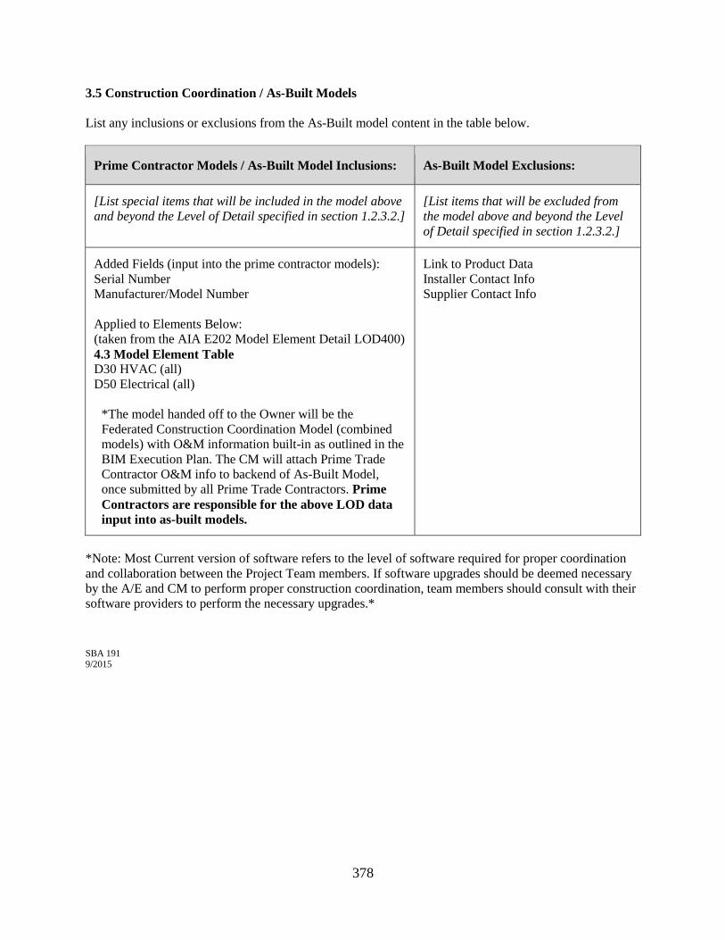
3.5 Construction Coordination / As-Built Models
List any inclusions or exclusions from the As-Built model content in the table below.
Prime Contractor Models / As-Built Model Inclusions: As-Built Model Exclusions:
[List special items that will be included in the model above
and beyond the Level of Detail specified in section 1.2.3.2.]
[List items that will be excluded from
the model above and beyond the Level
of Detail specified in section 1.2.3.2.]
Added Fields (input into the prime contractor models):
Serial Number
Manufacturer/Model Number
Applied to Elements Below:
(taken from the AIA E202 Model Element Detail LOD400)
4.3 Model Element Table
D30 HVAC (all)
D50 Electrical (all)
*The model handed off to the Owner will be the
Federated Construction Coordination Model (combined
models) with O&M information built-in as outlined in the
BIM Execution Plan. The CM will attach Prime Trade
Contractor O&M info to backend of As-Built Model,
once submitted by all Prime Trade Contractors. Prime
Contractors are responsible for the above LOD data
input into as-built models.
Link to Product Data
Installer Contact Info
Supplier Contact Info
*Note: Most Current version of software refers to the level of software required for proper coordination
and collaboration between the Project Team members. If software upgrades should be deemed necessary
by the A/E and CM to perform proper construction coordination, team members should consult with their
software providers to perform the necessary upgrades.*
SBA 191 9/2015