scholars research library · vertical electrical sounding (ves) using the schlumberger array...
TRANSCRIPT

Available online at www.scholarsresearchlibrary.com
Scholars Research Library
Archives of Physics Research, 2012, 3 (3):221-231 (http://scholarsresearchlibrary.com/archive.html)
ISSN : 0976-0970
CODEN (USA): APRRC7
221 Scholars Research Library
Geoelectrical assessment of university of ilorin dam axis
Olasunkanmi N. K.1, Olatunji s.1, Akoshile C. O.1, Nwankwo L. I.1
1Department of Physics, University of Ilorin, P. M. B. 1515, Ilorin, Nigeria. ______________________________________________________________________________
ABSTRACT Geophysical investigation has been undertaken at an existing dam site within the main campus of University of Ilorin, located around the southern flank of the Nigerian basement complex in West central part of Nigeria. This is aimed at evaluating the geo-structural setting of the concealed bedrock, the fracture pattern and possible dam seepage along the dam axis and its banks. Vertical Electrical Sounding (VES) technique of Schlumberger electrode configuration method was used for the field study. Twenty seven VES stations on eight profiles were established along the West-East flank of the dam. The three major lithologic units delineated are the topsoil, weak/gravelly zone and the fracture/fresh basement. The geoelectric sections reveal fractured basement beneath 4 stations of which two (i.e. VES 1 and 10) are along the dam reservoir and the two starts at the depth of 10 m, extending downward. The geoelectric maps show high resistivity range of about 29-2613 Ωm and thickness range of 0.8-3.1 m. This is underlain by relatively low resistivity layer whose values loiters around 100 Ωm with thickness range of 1.8-11.3 m, indicating near surface bedrock straddled with basement depression or fracture. The fractured basement and low resistivity zone is considered inimical to the continued water retention or zone of anomalous seepage as there is no surface manifestation and significant water reduction can be experienced. This is considered as responsible for low water retention in the reservoir during the dry season. Keywords: Geoelectric Section, Pseudosections, Lithology, Seepage and Geometric factor. ______________________________________________________________________________
INTRODUCTION
The essential need for portable water supply has been the major concern of Nigeria, which prompted the construction of dams. One of such is the University of Ilorin dam for water retention to meet the need of the institution. A dam is a barrier of concrete or Earth that is built across a river or stream to obstruct or control the flow of water, especially in order to create a reservoir. Benefits provided by dams include water supplies for drinking, irrigation and industrial uses; flood control; hydroelectric power; recreation; and navigation. At the same time, dams also represent a risk to public safety. Dams require ongoing maintenance, monitoring, safety inspections, and sometimes even rehabilitation to continue safe service. Despite series of geotechnical studies preceding the construction of dams, there are still number of problems that dams are prone to. Such problems can be caused by existence of concealed fracture/faults, fissures, joints or shears which can greatly reduce the reservoir capacity of the dam (Akanmu et al., 2007). According to the chronicles of river basin management in Nigeria, there are apparent technical defects at many of existing dams which include seepage through dam foundation works, shortage of spillway flood capacity, decrease of effective storage due to excessive sediment inflow, damages of gates and valves due to reckless operations, extraordinary vegetation growth and severe erosion on dam slopes, extensive aquatic weed development over the reservoir area and so on. When nothing is done for these dam safety problems and
Olasunkanmi N. K et al Arch. Phy. Res., 2012, 3 (3):221-231 ______________________________________________________________________________
222 Scholars Research Library
related upkeep of dam functions, such dams may constitute a significant potential hazard to the downstream people and societies as reported by Akanmu et al. [1]. There are series of available methods in geophysical investigation of a dam depending on the nature and parameters to be investigated. Methods such as Gravity method (Gravity measurements define anomalous density within the Earth), Magnetic method (magnetic method explores small variations in magnetic mineralogy), Seismic method (Applicable in geo-environmental works for studying the structure, thickness, and hydrology of tailings and extent of acid mine drainage around mineral deposits), Electrical method (are directly applicable to hydrologic investigations, and can be used to identify structures, lithologies and others). For this work, Electrical method would be used. The Electrical method (Direct Current, D.C Resistivity method) to be used measures Earth resistivity anomalies (the inverse of conductivity) using a direct or low frequency alternating current source. Rocks are electrically conductive as consequences of ionic migration in pore space water and more rarely, electronic conduction through metallic luster minerals. Because metallic luster minerals typically do not provide long continuous circuit paths for conduction in the host rock, bulk-rock Resistivity is almost always controlled by water content and dissolved ionic species present. High porosity causes low resistivity in water-saturated rocks. Direct current techniques have application to a variety of mineral exploration and geo-environmental considerations related to various ore deposit types. Massive sulfide deposits are a direct low resistivity target, whereas clay alteration assemblages are an indirect low resistivity target within and around many hydrothermal systems. The wide range of Earth material Resistivity also makes the method applicable to identification of lithological chronology and structures that may control mineralization. Acid mine waste, because of high hydrogen ion mobility, provides a more conductive target than solutions containing equivalent concentrations of neutral salts. The aim of this study is to evaluate the geo-structural setting of the concealed bedrock along the dam axis and its banks, the fracture pattern and possible dam seepage.
8° 29'
8° 28'
4° 39' 4° 40'
4° 39' 4° 40'
8° 29'
8° 28'
STAFF QUARTERSUNJLORIN PRY SCHOOL
UNILORIN SECONDARY SCHOOL
UNILORIN DAM
RECEPTION GROUND
WORKS (ADMIN)
PG HOTEL
SCHOOL CLINIC
SUGBUILDING
GT BANKSKY BANKUNILORIN
CENTRALMOSQUE
SENATEBUILDING
SUGAR RESERCH INSTITUTE
FACULTY OF ENGINEERING
MAIN CAMPUS GATE
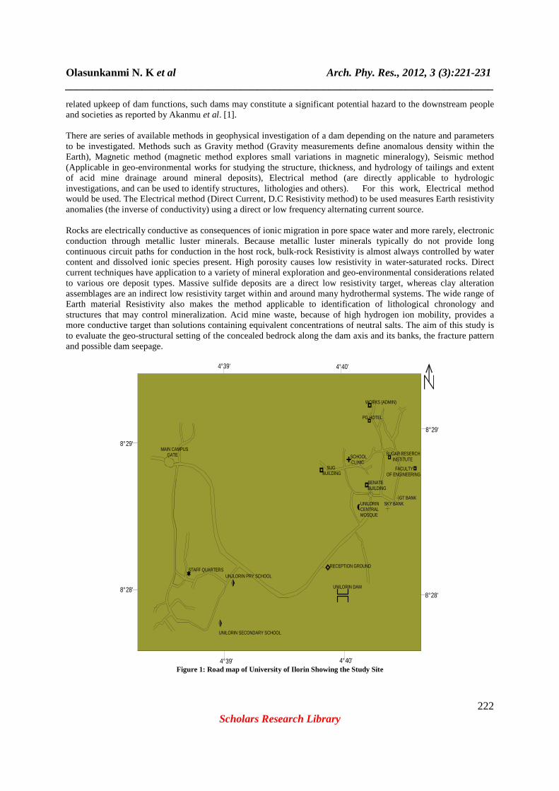
Figure 1: Road map of University of Ilorin Showing the Study Site
Olasunkanmi N. K et al Arch. Phy. Res., 2012, 3 (3):221-231 ______________________________________________________________________________
223 Scholars Research Library
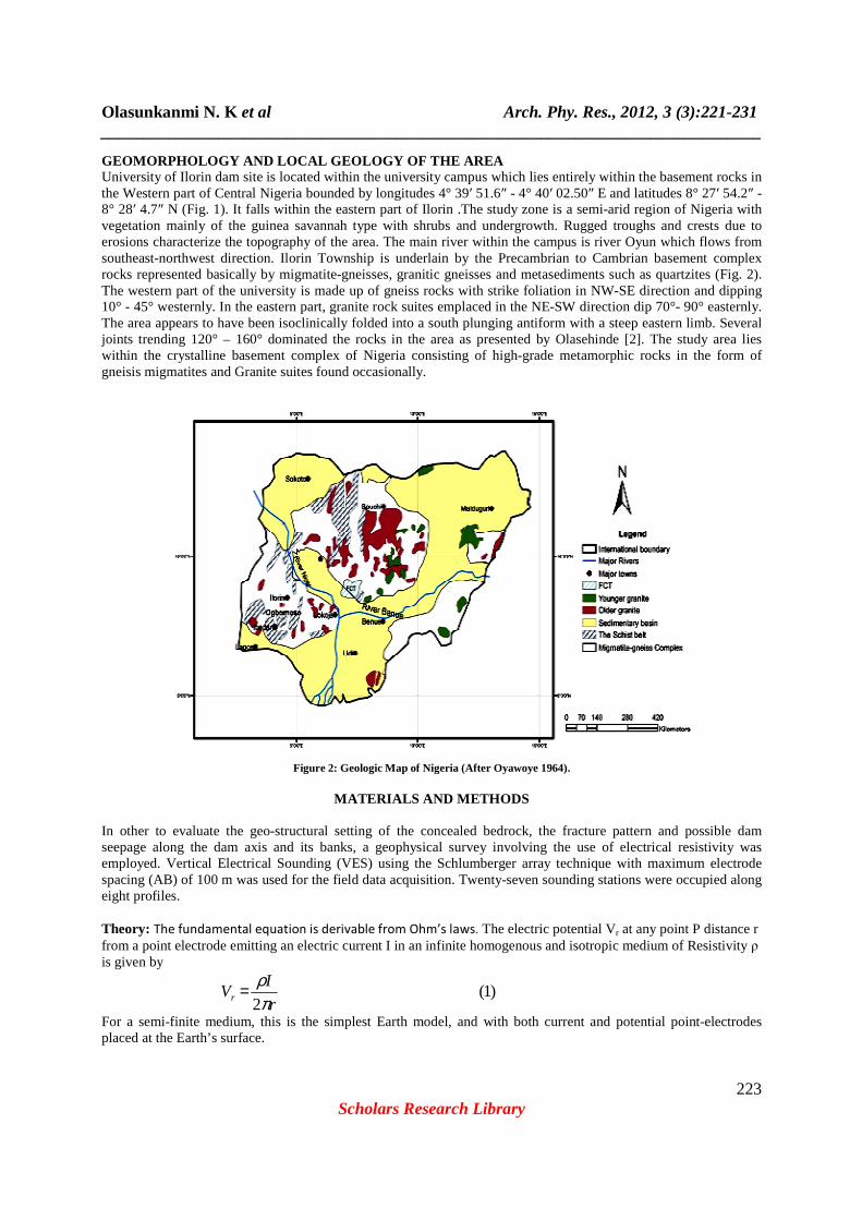
GEOMORPHOLOGY AND LOCAL GEOLOGY OF THE AREA University of Ilorin dam site is located within the university campus which lies entirely within the basement rocks in the Western part of Central Nigeria bounded by longitudes 4° 39′ 51.6″ - 4° 40′ 02.50″ E and latitudes 8° 27′ 54.2″ - 8° 28′ 4.7″ N (Fig. 1). It falls within the eastern part of Ilorin .The study zone is a semi-arid region of Nigeria with vegetation mainly of the guinea savannah type with shrubs and undergrowth. Rugged troughs and crests due to erosions characterize the topography of the area. The main river within the campus is river Oyun which flows from southeast-northwest direction. Ilorin Township is underlain by the Precambrian to Cambrian basement complex rocks represented basically by migmatite-gneisses, granitic gneisses and metasediments such as quartzites (Fig. 2). The western part of the university is made up of gneiss rocks with strike foliation in NW-SE direction and dipping 10° - 45° westernly. In the eastern part, granite rock suites emplaced in the NE-SW direction dip 70°- 90° easternly. The area appears to have been isoclinically folded into a south plunging antiform with a steep eastern limb. Several joints trending 120° – 160° dominated the rocks in the area as presented by Olasehinde [2]. The study area lies within the crystalline basement complex of Nigeria consisting of high-grade metamorphic rocks in the form of gneisis migmatites and Granite suites found occasionally.
Figure 2: Geologic Map of Nigeria (After Oyawoye 1964).
MATERIALS AND METHODS
In other to evaluate the geo-structural setting of the concealed bedrock, the fracture pattern and possible dam seepage along the dam axis and its banks, a geophysical survey involving the use of electrical resistivity was employed. Vertical Electrical Sounding (VES) using the Schlumberger array technique with maximum electrode spacing (AB) of 100 m was used for the field data acquisition. Twenty-seven sounding stations were occupied along eight profiles. Theory: The fundamental equation is derivable from Ohm’s laws. The electric potential Vr at any point P distance r from a point electrode emitting an electric current I in an infinite homogenous and isotropic medium of Resistivity ρ is given by
)1(2 r
IVr π
ρ=
For a semi-finite medium, this is the simplest Earth model, and with both current and potential point-electrodes placed at the Earth’s surface.
Olasunkanmi N. K et al Arch. Phy. Res., 2012, 3 (3):221-231 ______________________________________________________________________________
224 Scholars Research Library
( ) )2(2 rI
V πρ =
Irrespective of surface location and electrode spread, the resistivity is constant in a homogenous and isotropic ground. However, it does vary with the relative positions of electrodes when there is presence of subsurface
inhomogeneities and any computed value is known as apparent resistivity aρ .
( ) )3(2 rI
Va πρ ∆=
For Schlumberger technique used the Geometric factor G is thus given as:
)4(
22
222
22
−
=MN
MNAB
G π
)5(.. GRGI
VG =∆= π
Where R is the measured resistance and is the Geometric Constant which is a function of the electrode
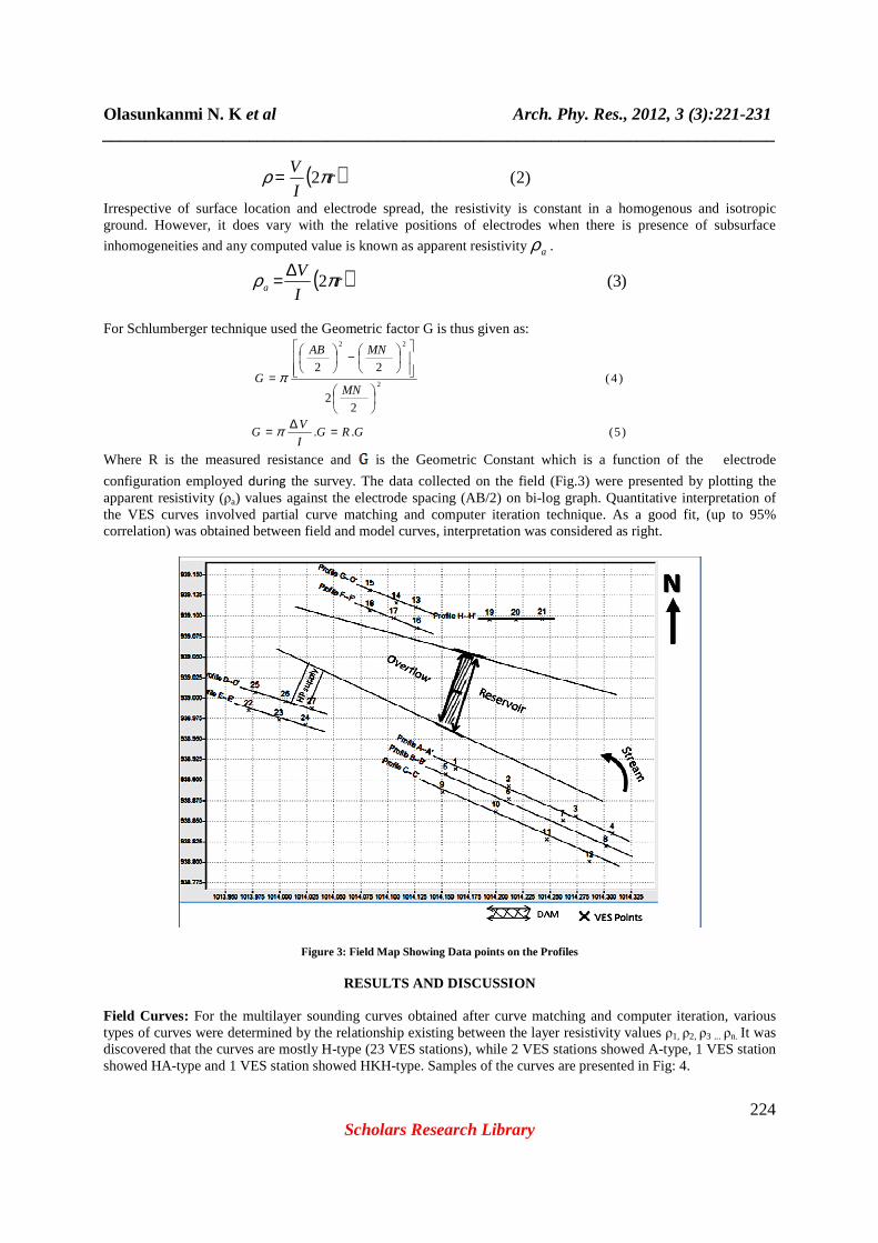
configuration employed during the survey. The data collected on the field (Fig.3) were presented by plotting the apparent resistivity (ρa) values against the electrode spacing (AB/2) on bi-log graph. Quantitative interpretation of the VES curves involved partial curve matching and computer iteration technique. As a good fit, (up to 95% correlation) was obtained between field and model curves, interpretation was considered as right.
Figure 3: Field Map Showing Data points on the Profiles
RESULTS AND DISCUSSION
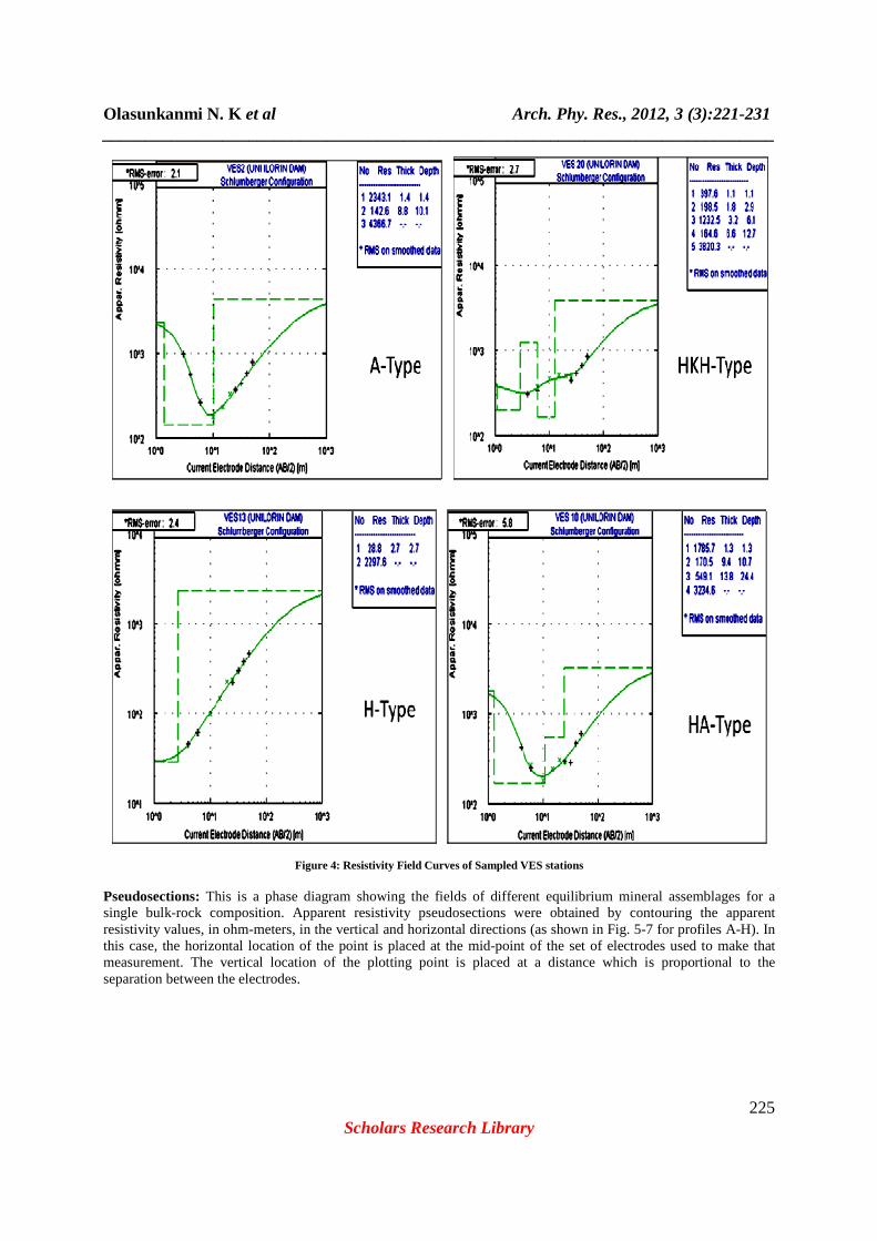
Field Curves: For the multilayer sounding curves obtained after curve matching and computer iteration, various types of curves were determined by the relationship existing between the layer resistivity values ρ1, ρ2, ρ3 ... ρn. It was discovered that the curves are mostly H-type (23 VES stations), while 2 VES stations showed A-type, 1 VES station showed HA-type and 1 VES station showed HKH-type. Samples of the curves are presented in Fig: 4.
Olasunkanmi N. K et al Arch. Phy. Res., 2012, 3 (3):221-231 ______________________________________________________________________________
225 Scholars Research Library
Figure 4: Resistivity Field Curves of Sampled VES stations Pseudosections: This is a phase diagram showing the fields of different equilibrium mineral assemblages for a single bulk-rock composition. Apparent resistivity pseudosections were obtained by contouring the apparent resistivity values, in ohm-meters, in the vertical and horizontal directions (as shown in Fig. 5-7 for profiles A-H). In this case, the horizontal location of the point is placed at the mid-point of the set of electrodes used to make that measurement. The vertical location of the plotting point is placed at a distance which is proportional to the separation between the electrodes.

Olasunkanmi N. K et al Arch. Phy. Res., 2012, 3 (3):221-231 ______________________________________________________________________________
226 Scholars Research Library
Figure 5: Vertical Pseuodosections

Olasunkanmi N. K et al Arch. Phy. Res., 2012, 3 (3):221-231 ______________________________________________________________________________
227 Scholars Research Library
Fig. 6: Vertical Psuodosections

Olasunkanmi N. K et al Arch. Phy. Res., 2012, 3 (3):221-231 ______________________________________________________________________________
228 Scholars Research Library
Fig. 7: Vertical Psuodosections
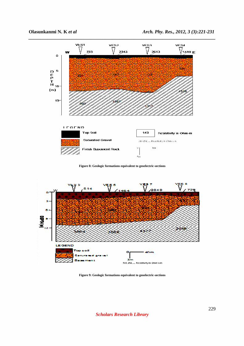
The sections show apparent resistivity value variations and the characteristics at different depths. The resistivity variation in the surface layer have the range of 28.8 Ωm to 2612 Ωm, which shows that the texture of the rock constituent is hard and dry due to high exposure to intense radiation from the sun. At a depth of about 4 m to 35 m, a relatively weak zone with apparent resistivity value ranging from 100 Ωm to 342 Ωm is shown in most profiles. It forms a laterally elongated structure in the form of void. This weak zone could be as a result of water percolation or as the tip of a weathered rock of the basement rock underlying the area. Equivalent Geologic Formations: The results of the interpreted VES curves were used to draw 2D geologic formation along some preferred profiles to show the vertical distribution of the rock matrices equivalent to the Resistivity within the volume of the Earth in the investigated area. The geoelectricsections show both vertical and lateral variations in layer resistivity, which is a revelation of the lateral and vertical face changes inferred from the apparent resistivity pseudosection. A maximum of three subsurface geoelectric units were delineated beneath these sections (Fig. 8-11). These include the topsoil, the gravelly/weathered rock, and the fractured/fresh bedrock.
Olasunkanmi N. K et al Arch. Phy. Res., 2012, 3 (3):221-231 ______________________________________________________________________________
229 Scholars Research Library
Figure 8: Geologic formations equivalent to geoelectric-sections
Figure 9: Geologic formations equivalent to geoelectric-sections

Olasunkanmi N. K et al Arch. Phy. Res., 2012, 3 (3):221-231 ______________________________________________________________________________
230 Scholars Research Library
Figure 10: Geologic formations equivalent to geoelectric-sections
Figure 11: Geologic formations equivalent to geoelectric-sections
CONCLUSION
The field resistivity measurements have revealed that the near surface basement which are expected to serve as the sealing barrier for water retention in the reservoir show no fracture signature. The fractures probably did not reach the surface, as it occurs after the second layer of the areas and in agreement with Olasehinde [3], and Taiwo [6], that both suggested that river Oyun is highly fractured controlled. Hence no seepage is likely to occur on these flanks. The suspected fractured basement was observed beneath 4 stations viz: VES 1, 10, 19 and 21, out of which VES 1 and 10 stood along the dam bank and started at the depth of 10 m proceeding downward. These can be considered
Olasunkanmi N. K et al Arch. Phy. Res., 2012, 3 (3):221-231 ______________________________________________________________________________
231 Scholars Research Library
inimical to the continued water retention or zone of anomalous seepage but no surface manifestation and significant water reduction experienced. The presence of fracture is generally accompanied by high fluid streaming potential and substantial water can be lost through the fractures thus initiating the weakening of the dam foundation, (Oyeneye et al., [5]. The low resistivity areas, weak zones, delineated by the geoelectric map present little or no risk of reservoir water seepage but may be the water table or the area is extensively marshy, capable of retaining water to the ground surface level.
REFERENCE
[1] J.O. Akanmu , O. Eluwa and I. Ekpo , Chronicles of river basin management in Nigeria. A journal presented at the international congress on river basin management, 2007. Correspondence email: ([email protected]). [2] P.I. Olasehinde, Elucidating fracture patterns of the Nigerian Basement Complex using electrical resistivity method. Z. Angew. Geowiss. Heff.1989, 8, 5, pp.109-120. [3] P.I. Olasehinde, An Integrated Geologic and Geophysical Exploration Technique for Groundwater in the Basement Complex of West Central part of Nigeria. Water ResourceJournal of NAH , 1999, 2, pp 46-49. [4] M.O. Oyawoye, The Geology of the Nigeria Basement Complex, Journal of Nigeria Mining, Geology and Metallurgy Soc., 1964, Vol. 1.pp.56-65 [5] O. Oyeneye, I. Oladapo, and S. Folami , Geoelectrical study of Dam Site of Federal College of Agriculture. South Western Nigeria, Journal of Medwell online, 2007,Vol., 2, No. 10, PP 1048 – 1056. [6] K.A. Taiwo, Dam Failure: A geophysical case study of Unilorin weir. An M.Sc. Seminar presented at the department of geology and mineral science, University of Ilorin, 1998.