schemeexplorationandperformanceanalysisof800-meter...
TRANSCRIPT

Research ArticleScheme Exploration and Performance Analysis of 800-MeterSuperlarge Span Structure
Deshen Chen,1 Hongliang Qian ,1 Huajie Wang,1 and Yue Wu 2
1Department of Civil Engineering, Harbin Institute of Technology at Weihai, Weihai 264209, China2School of Civil Engineering, Key Laboratory of Structures Dynamic Behavior and Control of the Ministry of Education,Harbin Institute of Technology, Harbin 150090, China
Correspondence should be addressed to Hongliang Qian; [email protected]
Received 11 June 2018; Accepted 1 August 2018; Published 3 September 2018
Academic Editor: Rosario Montuori
Copyright © 2018 Deshen Chen et al. 'is is an open access article distributed under the Creative Commons Attribution License,which permits unrestricted use, distribution, and reproduction in any medium, provided the original work is properly cited.
Superlarge span structure is one of the important trends for future building development. Under the background of the 800-metersuperlarge span dome project proposed by China Construction Group, this paper focuses on the structural optimization andperformance analysis of this superlarge span structure. 'e previous ideas of the superdome and the maximum span of existedspatial structures are reviewed, and some structural form selection principles are put forward which lay foundation for structuralselection. 'e applicability of high-strength steel and aluminum alloy is also discussed. It is demonstrated that the high-strengthsteel and aluminum alloy contribute little to structural comprehensive performances.'en, considering the effects of grid division,members topological relation, and surface shape, six kinds of rigid systems are contrastively studied to determine the optimalscheme.'e structural performances along with the increasing span are explored in detail. To further reduce the structural weightand improve mechanical performance, a new composite scheme and the cable-stayed megastructure are proposed and studied.'e research methods and performance analysis results can provide significant references for the following research on thesuperlarge span structure.
1. Introduction
As new materials and advanced engineering technologiesincreasingly emerge, the development of the large spanspatial structure has made great strides and the concept ofthe superlong span dome has been put forward. Sucha superdome can keep a warm and humid climate insideeven when built in the cold and dry area. Moreover, byunified planning in such a grander scale, the superdome canalso make a significant contribution to energy saving andemission reduction of the modern cities.
From the 1960s, some leading architects began to diginto this field and raised a number of conceptual designs.Fuller put forward a famous project named “Manhattandome” [1]. A super geodesic dome in the size of 3200mdiameter and 1600m height is designed to cover theManhattan block. It not only provides a comfortable en-vironment but also reduces the large expenses of air con-ditioning and winter snow removal. Frei Otto proposed
a superdome project named “the Arctic city” [2], a 2000mdiameter inflatable membrane dome built in the Arctic, andaimed at improving the working condition for polar sci-entists, as shown in Figure 1(a). Besides, to resist hurricanesand heat waves, American engineers proposed to builda superdome in the size of 1600m diameter and 450m heightover Houston [3], as shown in Figure 1(b). 'e designconsulted the three-layer structure of the Garden of Eden inBritain. An American company specializing in the designand installation of the cable membrane structure proposedthe “Spantheon system” for the superlong span dome, asshown in Figure 1(c). It consists of a number of huge archtrusses covered by the light cable membrane structure [4].But this research field has just started in China. ChinaConstruction Group is carrying out the project named“TianQiong,” as shown in Figure 1(d). 'e project is an 800-meter span superdome isolating the external harsh naturalcondition and simulating the real climate inside.'e tropicalocean even lifestyle can be created in severe cold regions.
HindawiAdvances in Civil EngineeringVolume 2018, Article ID 5159218, 10 pageshttps://doi.org/10.1155/2018/5159218

'is paper initially explores the comprehensive per-formance of the 800-meter span structure. Some basicprinciples are put forward, and the applicability of high-strength steel and aluminum alloy is also discussed. Six rigidstructural systems and two rigid-flexible composite schemesare studied by the numerical method. 'e changes ofstructural performance along with the increasing spans arealso given. 'en, the optimum scheme for the 800m spansuperdome, in certain conditions, will be obtained throughcontrastive analysis.
2. Design Principle and Material Selection
2.1. Representative Works of Spatial Structures. Table 1 givesrepresentative projects of the common spatial structureforms which have the largest spans. It can be seen clearly thatthe maximum span of the spatial structure has alreadyexceeded 300m, and the suspension bridge has reachednearly 2000m. What kind of structural system is the bestchoice for the superdome? From the existing engineeringpractices, some basic principles can be summed up: (1) thetransmission path of internal force should be simple andefficient. 'e components mainly in axial stress can makefull use of material properties. (2) 'e light roofing materialshould be used to cover the larger area with less material andimprove the daylighting. (3) 'e main structure should be
landed on the ground, and the horizontal thrust needs to bereduced as far as possible to relieve the pressure offoundation.
2.2. Load Values and Design Combinations. 'e loads in thedesign stage consider dead load, live load, wind load, andtemperature effect. 'e dead load includes the roof load andthe weight of structural components. 'e roof load is cal-culated by the developed area in the value of 100 kg/m2. 'elive load is calculated by the projection area in the value of50 kg/m2. According to the Chinese load code for the designof building structures (GB50009-2012) [19], the wind loadtakes the B class of surface roughness. 'e basic windpressure is 0.5 kN/m2, and the wind vibration coefficient is1.6. 'e shape coefficient is taken according to the rotatingdome in Table 8.3.1 of the Chinese load code (GB50009-2012). 'e whole structure temperature effect is consideredas ± 30°C. 'e load combinations of the bearing capacitylimit state are shown in Table 2. When it comes to structuralserviceability limit state, load combinations only considerthe combined factor in Table 2.
2.3. Structural Control Indexes. Strength index is the stressratio of member cross section in the full stress design, andthe limit is 0.8 with the consideration of member stability.
(a)
Apex ventsPanel safety
Dirigible
Space frameConstruction
Dome entrance
Dome geometry
(b)
(c) (d)
Figure 1: Some superlong span dome projects: (a) the Arctic city; (b) Houston dome; (c) Spantheon structure; (d) Tian Qiong.
2 Advances in Civil Engineering

For the cables, the maximum axial force in the ultimate stateof load capacity is not more than 0.5 times the minimumbreaking force and cables in the main structure are notallowed to appear slack. In addition, according to thetechnical specification for space frame structures (JGJ7-2010) [20], the deflection limit of single-layer and double-layer latticed shells are L/400 and L/250, respectively, and Lis the structural span. In this study, the deflection limit isassumed to L/500. With the span increasing, the stability hasgradually become the control factor of the design. 'eelastic-plastic stability coefficient is calculated under thestandard combination of the dead load and live load, and theelastic stability coefficient is also used as a reference.
2.4. Material Selection. Taken the double-layer reticulatedshell in the span of 800m and height of 200m for instance,the applicability of high-strength steel and aluminum alloy isdiscussed. According to the code for the design of steelstructures (GB50017-2003) [21], the code for the design ofhigh-strength steel structures (under preparation) [22, 23]and the code for the design of aluminum structures(GB50429-2007) [24], three types of high-strength steelincluding Q420, Q690, and Q960 and the high-strengthaluminum alloy 6061 T6 are selected for the structuraldesign.'e Q420 type is designed according to the front twocodes, respectively (Q420S for the steel structures code andQ420 for the high-strength steel structures code).
'e material consumption, deflection, and stabilityperformance are shown in Figure 2. Compared with Q420S,6061 T6 type can almost reduce structural weight by half, butthe deflection increases about 65.8%. 'e density and elasticmodulus of the aluminum alloy is only about 1/3 of steel.'emember section and material volume usage are both larger,and the structure stability becomes worse. Besides, thewelding performance of the aluminum alloy is poor, andjoint connection is more difficult. 'ematerial consumptionof Q420 can be reduced by 7.7% compared with Q420S.
From Q420 to Q960, the material consumption only de-creases by 7.0% which indicates that raising materialstrength contributes little to the economy. 'e deflection isalmost inversely proportional to the material consumption.'e elastic stability coefficients decrease while the elastic-plastic stability coefficients increase. Because the elasticstability coefficient is mainly affected by the member section,and the elastic-plastic stability coefficient is mainly affectedby the yield point of the material. 'erefore, the applicationof high-strength steel and aluminum alloy has little im-provement in the structural comprehensive performances.'erefore, the Q420S type is used in the following schemestudy. Besides, the cable in strength of 1860MPa is usedaccording to the technical specification of cable structures(JGJ257-2012) [25].
3. Rigid Structural Systems for the Superdome
Rigid structural systems are the most widely used forms inspatial structures. 'e reticulated shell and reticulated
Table 1: Representative works of different spatial structure forms.
Forms Representative works Span (m) Country Time Characteristics
Flatbed gridIndoor football field of Shenyang Expo
Center [5] 144 China 2001 Two-way orthogonal positive grid
Wuhan Optics Valley Tennis Center [6] 151 China 2015 'ree-layer grid with middle retractable roof
Reticulated shell Fukuoka Dome [7] 222 Japan 1993 Retractable roof composed of three fan-shaped shells
Shenyang Culture and Art Center [8] 110 China 2013 Single-layer folded plate shellMegastructure Gymnasium of Dalian Sports Center [9] 145 China 2013 Ellipse-shaped megastructure suspendome
Pipe truss arch Dongsheng Stadium in Ordos [10] 330 China 2011 Quadrilateral tube truss archGabon National Stadium [11] 320 Gabon 2011 Inverted triangle truss arch
String structureDongying Yellow River Estuary Model
Hall [12] 148 China 2009 Unidirectional truss string structure
Jinan Olympic Sports Center Stadium [13] 122 China 2008 Suspended lattice shell
Cable structureMillennium Dome [14] 320 Britain 1998 Cable net with 12 mast supports
'e Centennial Olympics Stadium [15] 191 America 1996 Ellipse plane cable dome'e Akashi Kaikyo Bridge (Kitagawa 2004) 1991 Japan 1999 Suspension bridge
Membranestructure
Shanghai World Expo Axis [16] 110 China 2009 Tensile membrane structureBaseball Hall of Tokyo [17] 205 Japan 1988 Gas-bearing membrane structure
Vista Alegre [18] 50 Spain 2001 Moored floating structure
Table 2: Load combinations of the bearing capacity limit state(partial factor× combined factor).
No. Combination Deadload
Liveload
Windload Temperature
1 D+L 1.35×1.0 1.4× 0.7 — —2 D+L 1.2×1.0 1.4×1.0 — —3 D+L+T 1.35×1.0 1.4× 0.7 — 1.4× 0.64 D+L+T 1.2×1.0 1.4×1.0 — 1.4× 0.65 D+L+W 1.35×1.0 1.4× 0.7 1.4× 0.6 —6 D+L+W 1.2×1.0 1.4×1.0 1.4× 0.6 —7 D+L+W 1.2×1.0 1.4× 0.7 1.4×1.0 —8 D+L+W+T 1.35×1.0 1.4× 0.7 1.4× 0.6 1.4× 0.69 D+L+W+T 1.2×1.0 1.4×1.0 1.4× 0.6 1.4× 0.610 D+L+W+T 1.2×1.0 1.4× 0.7 1.4×1.0 1.4× 0.611 D+W 1.0×1.0 — 1.4×1.0 —12 D+W+T 1.0×1.0 — 1.4×1.0 1.4× 0.6
Advances in Civil Engineering 3

megastructure are all typical representatives. �ey have theconcise and e�cient load transfer path, and the structuresare mainly in the state of membrane stress while thecomponents are axially loaded.
3.1. Structural Design. �e reticulated shell and reticulatedmegastructure are studied considering the e�ects of griddivision, members topological relation, and surface shape.As shown in Figure 3, six forms are involved in this studyincluding Kiewitt pyramidal spherical reticulated shell(KPS), geodesic pyramidal spherical reticulated shell (GPS),Kiewitt pyramidal catenoid reticulated shell (KPC), Kiewittspherical reticulated megastructure (KSM), rib-circlespherical reticulated megastructure (RSM), and rib-circle-reinforced spherical reticulated megastructure (RRSM). �estructural span is 800m, and the height is 200m. Accordingto the technical speci�cation for space frame structures(JGJ7-2010), the ratio of thickness to span is between 1/60and 1/30, and the practical ratio decreases gradually with theincrease of span. In this study, the ratio of thickness to spanis 1/80. For the reticulatedmegastructure, the size and heightof space truss are both 20m while in the strengthened re-gion, these values are both 10m. Structures are all supportedby �xed hinge bearings of bottom chords and radial con-straints are all released. Seen from the top view, the meg-astructure has better daylighting performance than thereticulated shell.
Figure 4 gives the statistical graphs for member sectiondistribution of di�erent schemes. For the reticulated shells,more than 98% of components have sections smaller thanϕ800× 24mm, and the biggest section is 2400× 76mm. Forthe reticulated megastructures, about 70% of componentshave section smaller than ϕ800× 24 and the biggest section is3600×120mm. �e element amount of RRSM is obviouslymore than the other two schemes. More than 83% ofcomponents have sections smaller than ϕ800× 24mm. Forthe member section design, more than 85% of members are
controlled by the design load combination of the dead loadand live load. �e wind load and temperature e�ect havelittle e�ect on the design internal force.
3.2. Performance Analysis. Figure 5 shows the analysis re-sults of steel consumption, de�ection, and stability perfor-mance. For the reticulated shells, the steel consumption ofthe geodesic type is 2.3% lower than the Kiewitt type, but thede�ection is 12.3% larger than the latter. �e catenoid re-ticulated shell consumes 3.9% more steel and has 5.6%smaller de�ection than the spherical reticulated shell. �ereis little di�erence of stability performance among threeschemes. For the reticulated megastructures, the steelconsumption of the Kiewitt type is 3.1% higher than the rib-circle type, but the de�ection is 5.9% smaller than the latter.�e rib-circle-reinforced type consumes 12.3% more steeland has 6.0% smaller de�ection than the rib-circle type.Moreover, the rib-circle type has the poorer stability per-formance than the other two schemes. On the whole, thereticulated shells have relatively smaller material con-sumption and de�ection than the reticulated mega-structures. �e stability performance is similar and littlesubjected to the in�uence of imperfection. Considering thestructural design and overall structural performance, theKiewitt pyramidal spherical reticulated shell and Kiewittspherical reticulated megastructure are the optimal schemes.
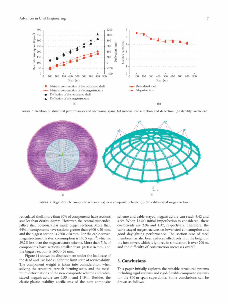
For these two schemes, considering the structural spanrange from 100m to 800m with the increment of 100m, thestructural performances along with increasing spans areexplored. Figure 6 shows the analysis results for steel con-sumption, de�ection, and stability performance. �e steelconsumption and de�ection of these two schemes bothincrease as the structural span becomes larger. �e mega-structure always consumes a little more steel material thanthe reticulated shell, and the former has larger de�ectionthan the latter. As the structural span increases, the dif-ferences of steel consumption are almost invariants all
0
300
600
900
1200
1500
0
40
80
120
160
200
6061 T6 Q420S Q420 Q690 Q960
Def
lect
ion
(m)
Mat
eria
l con
sum
ptio
n (k
g/m
2 )
Material type
Material consumptionDeflection
(a)
02468
1012141618
6061 T6 Q420S Q420 Q690 Q960
Stab
ility
coef
ficie
nt
Material type
Ideal elasticityElasticity with initial imperfectionIdeal elastoplasticityElastoplasticity with initial imperfection
(b)
Figure 2: Comparison of di�erent material types: (a) material consumption and de�ection; (b) stability coe�cient.
4 Advances in Civil Engineering

around 20kg/m2, while the differences of the deflection be-come larger changing from 25 to 125mm. Besides, for thestability performance, the elastoplastic stability coefficient ofthe reticulated shell considering initial imperfection goes downfaster than the megastructure. When the span is larger than300m, the megastructure has better stability performance.
4. Rigid-Flexible Composite Systems forthe Superdome
From the rigid system above, the great structural weight isthe most important load and even becomes a key factor fordetermining the feasibility of the scheme. To improve thestructural performance and reduce the structural weight, the
rigid-flexible composite systems consisting of rigid com-ponents and flexible cables are taken into consideration.Because of the enormous support reaction the shell has to besupported on the ground. In order to obtain enough servicespace, the combination of the central suspended lattice shelland double-reticulated shell around can be a new scheme.'is new composite scheme and the cable-stayed mega-structure are taken into consideration for the superdome.
4.1. Structural Design. 'e rigid-flexible composite schemesare shown in Figures 7(a) and 7(b). For the new compositescheme, the rigid substructure is the K6 pyramid sphericalreticulated shell in the grid division of 40 loops.'e thickness
(a) (b)
(c) (d)
(e) (f )
Figure 3: Six kinds of traditional rigid structural systems: (a) Kiewitt triangular pyramidal spherical reticulated shell (KPS); (b) geodesictriangular pyramidal spherical reticulated shell (GPS); (c) Kiewitt triangular pyramidal catenoid reticulated shell (KPC); (d) Kiewittspherical reticulated megastructure (KSM); (e) rib-circle spherical reticulated megastructure (RSM); (f ) rib-circle-reinforced sphericalreticulated megastructure (RRSM).
Advances in Civil Engineering 5

is 10m, and the top 17 loops are replaced by the suspendedlattice shell. �ere are 16 groups of hoop cables in the hor-izontal distance of 12m. From inside out, every group of hoopcables has a corresponding number from 1 to 16. �e cable-stayed megastructure is composed of rib-circle spherical re-ticulated megastructure and 9 groups of stay cables. �e mainribs are made up of three-layer space truss, and each group ofstay cables has four cables connected with adjacent nodes ofintersection on main ribs. �e structural spans are both800m, and the height is 200m; they are both supported by�xed hinge bearings, and radial constraints are all released.
�e design process of rigid-�exible composite systems isshown in Figure 8. Fully stressed design and form-�ndinganalysis should be carried out repeatedly and alternatelyuntil the structure gets to a steady state. �e inverse iterationmethod is used to adjust the structural lofting state shape,and the tension compensation method is used to adjust the
cable initial pretension of the lofting state [26]. �e controlindexes of form-�nding analysis are geometric con�gurationdeviation and cable pretension design value deviation in theprestressed equilibrium state.
4.2. Performance Analysis. Figure 9 gives the pretensiondesign results and the ratio of pretension to breaking force foreach hoop cable of the new composite scheme. �e cablepretension increases from the inside out. �e cables in ex-ternal loops contribute more to the structure. �e pretensiondesign values of the cable-stayed megastructure are 7622 kNof inner stay cables and 10857 kN of outer stay cables.
�e element ratio statistics of rigid components areshown in Figure 10. �e steel usage of the new compositescheme is 170.1 kg/m2, which is 5.6% less than the double-layer reticulated shell scheme. In the part of the double-layer
0
0.1
0.2
0.3
0.4
0.5
0.6
0.7
Below400 × 16
Below800 × 24
Below1200 × 34
Below1800 × 54
Below2400 × 76
Elem
ent s
tatis
tics
Section interval
KPSGPSKPC
(a)
0
0.1
0.2
0.3
0.4
0.5
0.6
Below400 × 16
Below800 × 24
Below1200 × 34
Below2000 × 54
Below3600 × 120
Elem
ent s
tatis
tics
Section interval
KSMRSMRRSM
(b)
Figure 4: Member section statistics of six schemes: (a) reticulated shells; (b) reticulated megastructure.
0
200
400
600
800
1000
1200
120
140
160
180
200
220
240
KPS GPS KPC KSM RSM RRSM
Mat
eria
l con
sum
ptio
n (k
g/m
2 )
Reticulated shell type
Material consumptionDeflection
Def
lect
ion
(mm
)
(a)
0
4
8
12
16
20
KPS GPS KPC KSM RSM RRSM
Stab
ility
coef
ficie
nt
Reticulated shell type
Ideal elasticityElasticity with imperfectionIdeal elastoplasticityElastoplasticity with imperfection
(b)
Figure 5: Structural performances of di�erent schemes: (a) material consumption and de�ection; (b) stability coe�cient.
6 Advances in Civil Engineering
reticulated shell, more than 90% of components have sectionssmaller than ϕ600× 20mm. However, the central suspendedlattice shell obviously has much bigger sections. More than94% of components have sections greater than ϕ600× 20mm,and the biggest section is 2800× 58mm. For the cable-stayedmegastructure, the steel consumption is 140.5 kg/m2, which is29.2% less than the megastructure scheme. More than 71% ofcomponents have sections smaller than ϕ400×16mm, andthe biggest section is 1600× 38mm.
Figure 11 shows the displacement under the load case ofthe dead and live loads under the limit state of serviceability.�e component weight is taken into consideration whensolving the structural stretch-forming state, and the maxi-mum deformations of the new composite scheme and cable-stayed megastructure are 0.55m and 1.19m. Besides, theelastic-plastic stability coe�cients of the new composite
scheme and cable-stayed megastructure can reach 3.42 and4.59. When L/300 initial imperfection is considered, thesecoe�cients are 2.94 and 4.37, respectively. �erefore, thecable-stayed megastructure has lower steel consumption andgood daylighting performance. �e section size of steelmembers has also been reduced e�ectively. But the height ofthe host tower, which is ignored in simulation, is over 200m,and the di�culty of construction increases overall.
5. Conclusions
�is paper initially explores the suitable structural systemsincluding rigid systems and rigid-�exible composite systemsfor the 800m span superdome. Some conclusions can bedrawn as follows:
–400
–200
0
200
400
600
800
1000
1200
0
50
100
150
200
250
300
350
400
0 100 200 300 400 500 600 700 800 900
Def
lect
ion
(mm
)
Mat
eria
l con
sum
ptio
n (k
g/m
2 )
Span (m)
Material consumption of the reticulated shellMaterial consumption of the megastructureDeflection of the reticulated shellDeflection of the megastructure
(a)
0
1
2
3
4
5
6
0 100 200 300 400 500 600 700 800 900
Stab
ility
coef
ficie
nt
Span (m)
Reticulated shellMegastructure
(b)
Figure 6: Relation of structural performances and increasing spans: (a) material consumption and de�ection; (b) stability coe�cient.
(a) (b)
Figure 7: Rigid-�exible composite schemes: (a) new composite scheme; (b) the cable-stayed megastructure.
Advances in Civil Engineering 7

Initial section Design value ofpretension
Form-finding analysis
Fully stressed design
Form-finding analysis
Accuracyrequirement
Structure scheme
Y
N
Figure 8: Design process of the rigid-�exible composite scheme.
–0.4
–0.2
0
0.2
0.4
0.6
0
5000
10000
15000
20000
25000
0 1 2 3 4 5 6 7 8 9 10 11 12 13 14 15 16 17
Ratio
of b
reak
ing
forc
e
Pret
ensio
n de
sign
valu
e (kN
)
Cable numbers
Pretension design valueRatio of pretension to breaking force
Figure 9: Design results of ring cables.
0.00
0.05
0.10
0.15
0.20
0.25
0.30
0.35
0.40
Below219 × 10
Below400 × 16
Below600 × 20
Below800 × 24
Below1000 × 30
Below1400 × 38
Below2800 × 58
Elem
ent r
atio
stat
istic
s
Section interval
Double-reticulated shell aroundCentral suspended lattice shell
(a)
Below219 × 10
Below400 × 16
Below600 × 20
Below800 × 24
Below1000 × 30
Below1600 × 38
Double-reticulated shell around
0.00
0.05
0.10
0.15
0.20
0.25
0.30
0.35
0.40
Elem
ent r
atio
stat
istic
s
Section interval
(b)
Figure 10: Element ratio statistics of rigid components: (a) new composite scheme; (b) cable-stayed megastructure.
8 Advances in Civil Engineering

(1) �e application of the high-strength steel and alu-minum alloy has little improvements in structuralperformances. High-strength improves the elastic-plastic stability but contributes little to the materialconsumption. Aluminum alloy signi�cantly reducesthe structural weight, but the member section andmaterial volume usage both increase and the structurestability becomes worse.
(2) Considering the e�ects of grid division, memberstopological relation, and surface shape, the Kiewittpyramidal spherical reticulated shell and Kiewittspherical reticulated megastructure are the optimalrigid systems.�e steel consumptions are 180.1 kg/m2
and 198.5 kg/m2, respectively.(3) As the structural span becomes larger, the steel
consumption and de�ection both increase and themegastructure always consumes a little more ma-terial and has larger de�ection than the reticulatedshell. When the span is larger than 300m, themegastructure has better stability performance.
(4) A new composite scheme and the cable-stayedmegastructure are proposed for the superdome.�e cable-stayed megastructure has lower steelconsumption with the value of 140.5 kg/m2 andbetter structure stability. �e section size of steelmembers has also been reduced e�ectively.
Data Availability
�e data used to support the �ndings of this study areavailable from the corresponding author upon request.
Conflicts of Interest
�e authors declare that they have no con�icts of interest.
Acknowledgments
�e authors gratefully acknowledge the support of theNational Key Research and Development Program of China(no. 2016YFC0802003) and the National Natural ScienceFoundation of China (no. 51578186).
References
[1] P. Steadman, “Energy and patterns of land use,” Journal ofArchitectural Education, vol. 30, no. 3, pp. 62–67, 1976.
[2] I. S. Pinto, “Lightweight and transparent domes,” In-ternational Journal of Architectural Research, vol. 6, no. 3,pp. 124–134, 2012.
[3] R. Engelkemeir, S. D. Khan, and K. Burke, “Surface de-formation in Houston, Texas using GPS,” Tectonophysics,vol. 490, no. 1-2, pp. 47–54, 2010.
[4] Y.-G. Zhang, S.-D. Xue, Q.-S. Yang, and F. Fan, Large SpanSpatial Structure, China Machine Press, Beijing, China, 2ndedition, 2014, in Chinese.
[5] J. Ni, B. Cai, and G. Zhou, “Structural design of the roof of theindoor football stadium in Shenyang Exhibition Center,”Progress in Steel Building Structures, vol. 5, no. 3, pp. 1–5, 2003,in Chinese.
[6] L.-F. Zeng, W.-G. Dong, S.-Q. Wen, and X. Wang, “Resistprogressive collapse analysis of the Optics Valley TennisCenter,” in Proceedings of the Second International Conferenceon Large Buildings of Steel and Composite Structures,pp. 481–489, Shanghai, China, 2014.
[7] T. Yoshio, S. Yukio, and N. Masayoshi, “Fukuoka Dome,Japan,” Structural Engineering International, vol. 4, no. 3,pp. 151–153, 1994.
[8] B.-B. Zhu, Y.-R. Lin, X.-M. Xu, and Q.-Y. Zhou, “Study on thekey technologies of structural design of ShenyangCulture andArtCenter,” Building Structures, vol. 1, pp. 368–371, 2012, in Chinese.
[9] G.-B. Nie, F. Fan, and X.-D. Zhi, “Test on the suspended domestructure and joints of Dalian Gymnasium,” Advances inStructural Engineering, vol. 16, no. 3, pp. 467–485, 2013.
–0.554
–0.5
5393
5
–0.4
8966
8
–0.4
2540
2
–0.3
6113
5
–0.2
9686
9
–0.2
3260
2
–0.1
6833
6
–0.1
0406
9
–0.0
3980
3
0.02
4464
Nodal solution
SMX=0.024464SMN=–0.553935DMX=0.56704RSYS=0UZTime=1Sub=7Step=1
(AVG)
(a)
–1.1
8946
–1.0
5706
–0.9
2466
5
–0.7
9226
8
–0.6
5987
1
–0.5
2747
4
–0.3
9507
8
–0.2
6268
1
–0.1
3028
4
0.00
2112
–1.189
Nodal solution
SMX=0.002112SMN=–1.18946DMX=1.18951RSYS=0UZTime=1Sub=7Step=1
(AVG)
(b)
Figure 11: Displacement under the load case of the dead and live loads: (a) new composite scheme; (b) cable-stayed megastructure.
Advances in Civil Engineering 9

[10] Z.-G. Mu, J. Xiao, Y.-L. Shen, and Z. Fan, “Study on the arc-cable supported long span spatial structure of Erdos Dong-Sheng Stadium,” Advanced Materials Research, vol. 433–440,pp. 1836–1839, 2012.
[11] D.-J. Cao, C.-X. Hao, and F. Liu, “Design of the canopystructure of Gabon National Stadium,” Building Science,vol. 3, pp. 87–89, 2011, in Chinese.
[12] J.-Z. Wu, M.-L. Liu, B. Shen, and Y.-H. Zhang, “Vibrationfrequency testing and theoretical model research on cable oftruss string structure,” Building Structures, vol. 42, no. 10,pp. 79–82, 2012, in Chinese.
[13] X.-J. Zhou, “Structural design and health monitoring of JinanOlympic Sports Center,” EngineeringMechanics, vol. 27, no. 2,pp. 105–113, 2010.
[14] I. Liddell, T. Mclaughlin, T. Ross, and J. Phillips, “Engineeringdesign of the Millennium Dome,” Proceedings of the In-stitution of Civil Engineers-Civil Engineering, vol. 138, no. 5,pp. 42–51, 2000.
[15] M. Kiuri and S. Reiter, “Olympic stadium design: pastachievements and future challenges,” International Journal ofArchitectural Research, vol. 7, no. 2, pp. 102–117, 2013.
[16] M. Kitagawa, “Technology of the Akashi Kaikyo bridge,”Structural Control and Health Monitoring, vol. 11, no. 2,pp. 75–90, 2004.
[17] J. Knippers, “From model thinking to process design,” Ar-chitectural Design, vol. 83, no. 2, pp. 74–81, 2013.
[18] F. V. Jensen, Cover Elements for Retractable Roof Structures,University of Cambridge, Cambridge, UK, 2001.
[19] GB50009-2012, Load Code for the Design of Building Struc-tures, China Architectural & Building Press, Beijing, China,2012.
[20] JGJ7-2010, Technical Specification for Space Frame Structures,China Architectural & Building Press, Beijing, China, 2010.
[21] GB50017-2003, Code for Design of Steel Structures, ChinaArchitectural & Building Press, Beijing, China, 2003.
[22] H. Ban, G. Shi, Y. Shi, and Y. Wang, “Overall buckling be-havior of 460MPa high strength steel columns: experimentalinvestigation and design method,” Journal of ConstructionalSteel Research, vol. 74, pp. 140–150, 2012.
[23] G. Shi, H. Ban, and F. Bijlaard, “Tests and numerical study ofultra-high strength steel columns with end restraints,” Journalof Constructional Steel Research, vol. 70, pp. 236–247, 2012.
[24] GB50429-2007, Code for Design of Aluminum Structures,China Architectural & Building Press, Beijing, China, 2007.
[25] JGJ257-2012, Technical Specification for Cable Structures,China Architectural & Building Press, Beijing, China, 2012.
[26] X. F. Yuan and S. L. Dong, “Nonlinear analysis and optimumdesign of cable domes,” Engineering Structures, vol. 24, no. 7,pp. 965–977, 2002.
10 Advances in Civil Engineering

International Journal of
AerospaceEngineeringHindawiwww.hindawi.com Volume 2018
RoboticsJournal of
Hindawiwww.hindawi.com Volume 2018
Hindawiwww.hindawi.com Volume 2018
Active and Passive Electronic Components
VLSI Design
Hindawiwww.hindawi.com Volume 2018
Hindawiwww.hindawi.com Volume 2018
Shock and Vibration
Hindawiwww.hindawi.com Volume 2018
Civil EngineeringAdvances in
Acoustics and VibrationAdvances in
Hindawiwww.hindawi.com Volume 2018
Hindawiwww.hindawi.com Volume 2018
Electrical and Computer Engineering
Journal of
Advances inOptoElectronics
Hindawiwww.hindawi.com
Volume 2018
Hindawi Publishing Corporation http://www.hindawi.com Volume 2013Hindawiwww.hindawi.com
The Scientific World Journal
Volume 2018
Control Scienceand Engineering
Journal of
Hindawiwww.hindawi.com Volume 2018
Hindawiwww.hindawi.com
Journal ofEngineeringVolume 2018
SensorsJournal of
Hindawiwww.hindawi.com Volume 2018
International Journal of
RotatingMachinery
Hindawiwww.hindawi.com Volume 2018
Modelling &Simulationin EngineeringHindawiwww.hindawi.com Volume 2018
Hindawiwww.hindawi.com Volume 2018
Chemical EngineeringInternational Journal of Antennas and
Propagation
International Journal of
Hindawiwww.hindawi.com Volume 2018
Hindawiwww.hindawi.com Volume 2018
Navigation and Observation
International Journal of
Hindawi
www.hindawi.com Volume 2018
Advances in
Multimedia
Submit your manuscripts atwww.hindawi.com