sch.520.am.om.w.120112.en.c - download.nautilus.com
TRANSCRIPT

ASSEMBLY MANUAL / OWNER’S MANUAL Manual en Español Latino Americano:http://www.schwinnfitness.com
520

2
Important Safety Instructions - Assembly 3 Safety Warning Labels / Serial Number 4Specifications 5BeforeAssembly 5Parts 6Hardware 7Tools 7Assembly 8MovingtheMachine 15LevelingtheMachine 15
Important Safety Instructions 16Features 17 Console Features 18
Operations 21 Adjustments 21 Power Up / Idle Mode 21 Quick Start Program 21 Mounting and Dismounting 22 Custom Goal Programs 22 Paused / Results Mode 23Console Service Mode 24Maintenance 25 Replacing the Console Batteries 26 Maintenance Parts 27Troubleshooting 28Warranty 31
Nautilus,Inc.,(800)NAUTILUS/(800)628-8458,www.NautilusInc.com-CustomerService:NorthAmerica(800)605-3369,[email protected]|outsideU.S.+01-360-859-5180,[email protected]|PrintedinChina|©2012Nautilus,Inc.
Table of ConTenTs
Tovalidatewarrantysupport,keeptheoriginalproofofpurchaseandrecordthefollowinginformation:Serial Number __________________________Date of Purchase ____________________Toregisteryourproductwarranty,goto:www.SchwinnFitness.com/registerOrcall1(800)605–3369.Ifyouhavequestionsorproblemswithyourproduct,pleasecall1(800)NAUTILUS(628–8458).

3
ImporTanT safeTy InsTruCTIons- assembly
This icon means a potentially hazardous situation which, if not avoided, could result in death or serious injury.
Obey the following warnings:Read and understand all warnings on this machine.Carefully read and understand the Assembly instructions.
• Keepbystandersandchildrenawayfromtheproductyouareassemblingatalltimes.• Donotinstallthebatteriesintothemachineuntilinstructedtodoso.• Donotassemblethismachineoutdoorsorinawetormoistlocation.• Makesureassemblyisdoneinanappropriateworkspaceawayfromfoottrafficandexposuretobystanders.• Somecomponentsofthemachinecanbeheavyorawkward.Useasecondpersonwhendoingtheassemblysteps
involving these parts. Do not do steps that involve heavy lifting or awkward movements on your own.• Setupthismachineonasolid,level,horizontalsurface.• Donottrytochangethedesignorfunctionalityofthismachine.Thiscouldcompromisethesafetyofthismachineand
will void the warranty.• Ifreplacementpartsarenecessary,useonlygenuineNautilus® replacement parts and hardware. Failure to use
genuine replacement parts can cause a risk to users, keep the machine from operating correctly and void the warranty.
• DonotuseuntilthemachinehasbeenfullyassembledandinspectedforcorrectperformanceinaccordancewiththeManual.
• ReadandunderstandthecompleteManualsuppliedwiththismachinebeforefirstuse.KeeptheManualforfuturereference.
• Doallassemblystepsinthesequencegiven.Incorrectassemblycanleadtoinjuryorincorrectfunction.• Thisproductcontainsmagnets.Magneticfieldscaninterferewiththenormaluseofcertainmedicaldevicesataclose
range.Usersmaycomeintoproximityofthemagnetsintheassembly,maintenance,and/oruseoftheproduct.Giventhe obvious importance of these devices, such as a pacemaker, it is important that you consult with your medical provider in connection with the use of this equipment. Please consult the “Safety Warning Labels and Serial Number” section to determine the location of the magnets on this product.

4
safeTy WarnIng labels and serIal number
REVISIONSECO REVISION REV DESCRIPTION APPROVED DATE
TITLE.
PART NO.REV.
SHEET 1 OF 1SCALE: 1:1 DO NOT SCALE DRAWING
1. ALL ITEMS MUST BE RoHS COMPLIANT2. ALL DIMENSIONS APPLY BEFORE PLATING OR COATING.3. REMOVE ALL BURRS, BREAK SHARP EDGES 0.5 MM MAX.4. ALL MACHINES SURFACES Ra 3.2 uM.5. ALL APPLICABLE NAUTILUS STANDARDS AND SPECIFICATIONS APPLY.6. ALL DIMENSIONS ARE IN MILLIMETERS7. ALL DUAL DIMENSIONS ARE IN INCH
UNLESS OTHERWISE SPECIFIED:
METRICTHIRD ANGLE PROJECTION INTERPRET DIMENSIONS AND TOLERANCES
PER ASME Y14.5M - 1994
2.5 1.5 0.75 0.25 1°
X.X.XX.XXX.XXXANGULAR C
SIZE
This document is the property of Nautilus, Inc. It may not be reproduced in whole or part, provided to third parties, or used for any purposes other than the performance of work for Nautilus, Inc. without written authorization. All rights are reserved, including copyrights.
TOLERANCES.
DRAWN
DESIGNED
DATE
METRIC_C_REV G
NAUTILUS, INC.16400 SE NAUTILUS DRIVE, VANCOUVER, WA 98683 LIFECYCLE
- -
APPROVALS
- -
- - - -
WARRANTY ITEM:
D.LOVELY02 /03 / 2010
D.LOVELY A003-5800
GWl bikes and ellipticals 300lbs
MATERIAL.
COLOR. DIE LINE
PMS 152 PMS 109
BLACK
WHITE
Labels must be created from an agency approved tamper proof labeling system such as "UL Recognized component marking and labeling system (example: UL PGGU2) or equivalent. Label and adhesive must be rated for surface it is applied to (painted metal or ABS plastic), Label and adhesive must be rated for 60 degrees C minimum. Labels must meet UL 1647 Permanence of Marking Test.
50mm
82.3mm
NA NA RELEASED DLOVELY 2/3/2010
••
•
•
•
•
300lbs. (136kg).
Keep children away.Prior to use, read and understand the Owners Manual.Injury or death is possible if Caution is not used while using this machine.The maximum user weight for this machine is 300 lbs (136 Kg).Replace any “Caution” “Warning” or “Danger” label that is illegible, damaged, or removed.This machine is for home use only.
•
•
•
•
•
•
Serial Number
REVISIONSECO REVISION REV DESCRIPTION APPROVED DATE
TITLE.
PART NO.REV.
SHEET 1 OF 1SCALE: 1:1 DO NOT SCALE DRAWING
1. ALL ITEMS MUST BE RoHS COMPLIANT2. ALL DIMENSIONS APPLY BEFORE PLATING OR COATING.3. REMOVE ALL BURRS, BREAK SHARP EDGES 0.5 MM MAX.4. ALL MACHINES SURFACES Ra 3.2 uM.5. ALL APPLICABLE NAUTILUS STANDARDS AND SPECIFICATIONS APPLY.6. ALL DIMENSIONS ARE IN MILLIMETERS7. ALL DUAL DIMENSIONS ARE IN INCH
UNLESS OTHERWISE SPECIFIED:
METRICTHIRD ANGLE PROJECTION INTERPRET DIMENSIONS AND TOLERANCES
PER ASME Y14.5M - 1994
2.5 1.5 0.75 0.25 1°
X.X.XX.XXX.XXXANGULAR C
SIZE
TOLERANCES.
DRAWN
DESIGNED
DATE
METRIC_C_REV G
NAUTILUS, INC.16400 SE NAUTILUS DRIVE, VANCOUVER, WA 98683 LIFECYCLE
APPROVALS
- - - -
WARRANTY ITEM:
LSEVIER4/25/2012
LSEVIER A8000210
PRODUCT SPECIFICATION DECAL
MATERIAL.
COLOR. DIE LINE
BLACK
Labels must be created from an agency approved tamper proof labeling system such as "UL Recognized component marking and labeling system (example: UL PGGU2) or equivalent. Label and adhesive must be rated for surface it is applied to (painted metal or ABS plastic), Label and adhesive must be rated for 60 degrees C minimum. Labels must meet UL 1647 Permanence of Marking Test.
NOTE:
MM/YY - PRODUCTION DATE. THE SUPPLIER WILL FILL IN THIS DATE ON EACH UNIT BASEDON THE PRODUCTION DATE: MONTH AND YEAR.
JSTOB
COMPLIANCE
This document is the property of Nautilus, Inc. It may not be reproduced in whole or part, provided to third parties, or used for any purposes other than the performance of work for Nautilus, Inc. without written authorization. © Nautilus, Inc. This document is provided in con�dence and your acceptance of this document is your agreement to maintain the document in con�dence.
A RELEASEXXXXX LSEVIER 4/25/2012
18225 NE Riverside Parkway,Portland, Or. 97230www.nautilus.com Phone:1-800-NAUTILUSBrand: Schwinn Model: 520Rating: 9V 1.5A Class: H Accuracy: CFor consumer use onlyMaximum User Weight: 300lb (136k)Fitness EquipmentMade in: China
8000210_A
Manufacture Date:
40mm
45mm
Patent: www.nautilusinc.com/IP
Nautilus, Inc.
MM/YY
5
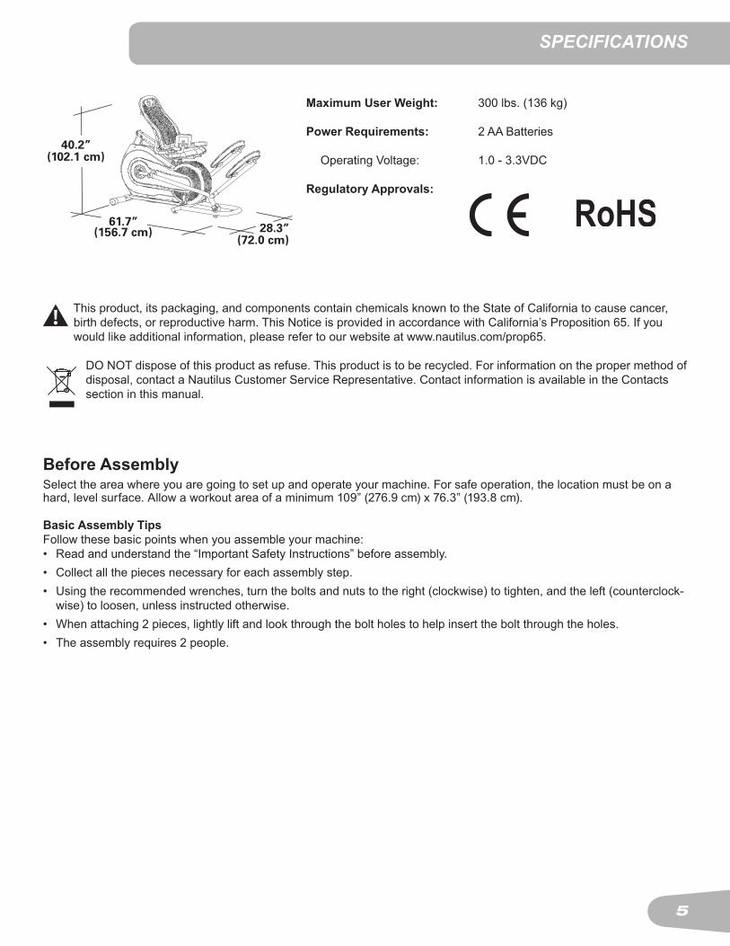
speCIfICaTIons
Before Assembly Select the area where you are going to set up and operate your machine. For safe operation, the location must be on a hard,levelsurface.Allowaworkoutareaofaminimum109”(276.9cm)x76.3”(193.8cm).
Basic Assembly TipsFollowthesebasicpointswhenyouassembleyourmachine:• Read and understand the “Important Safety Instructions” before assembly.• Collect all the pieces necessary for each assembly step.• Using the recommended wrenches, turn the bolts and nuts to the right (clockwise) to tighten, and the left (counterclock-
wise) to loosen, unless instructed otherwise.• When attaching 2 pieces, lightly lift and look through the bolt holes to help insert the bolt through the holes.• The assembly requires 2 people.
Maximum User Weight: 300 lbs. (136 kg)
Power Requirements: 2 AA Batteries
OperatingVoltage: 1.0-3.3VDC
Regulatory Approvals:
40.2”(102.1 cm)
28.3”(72.0 cm)
61.7”(156.7 cm)
This product, its packaging, and components contain chemicals known to the State of California to cause cancer, birthdefects,orreproductiveharm.ThisNoticeisprovidedinaccordancewithCalifornia’sProposition65.Ifyouwouldlikeadditionalinformation,pleaserefertoourwebsiteatwww.nautilus.com/prop65.
DO NOT dispose of this product as refuse. This product is to be recycled. For information on the proper method of disposal, contact a Nautilus Customer Service Representative. Contact information is available in the Contacts section in this manual.

6
A decal has been applied to all right (“ R ”) and left (“ L ”) parts to assist with assembly.
Item Qty Description Item Qty Description1 1 Frame 9 1 Rear Stabilizer2 1 Seat Bottom 10 1 Pedal, Left3 1 Seat Back 11 1 Pedal, Right4 1 Seat Frame 12 1 Rail Assembly5 1 Handlebar 13 1 Seat Rail6 1 Water Bottle Holder 14 1 Console Support Arm7 1 Leg, Left 15 1 Console8 1 Leg, Right
parTs
1
3
24
5
6
9
8
1112
13
15
14
10
7

7
HardWare / Tools
A B C D E F G H
I J K L M
Item Qty Description Item Qty DescriptionA 2 Washer, M16 H 4 ButtonHeadHexScrew,M8x1.25x38BlackB 2 Wave Washer I 4 ButtonHeadHexScrew,M6x1.0x12BlackC 2 Washer, M8 Wide J 6 ButtonHeadHexScrew,M8x1.25x20D 2 ButtonHeadHexScrew,M8x1.0x20Black K 6 PhillipsHeadScrew,M5x0.7x12BlackE 14 Washer, M8 Curved L 4 ButtonHeadHexScrew,M8x1.25x50BlackF 14 ButtonHeadHexScrew,M8x1.25x16Black M 16 Washer, M8G 2 ButtonHeadHexScrew,M8x1.25x12Black
ToolsIncluded Not Included
4 mm6 mm
(recommended)2 AA size batteries (LR6)
#2

8
1. Attach Rear Stabilizer to Frame
ASSEMBLY
2. Attach Rail Assembly to Frame Assembly NOTICE:Donotfullytightenthishardware.
12
X4
J
E
6mm
1
9
X2
JE
6mm

9
3. Attach the Handlebar to the Seat Frame
4
5
6mm
M H
X4
4. Attach the Seat Cushions to the Seat Frame Assembly
2
6mm
3
I
FM
X2
6mm
M
L
X2
X4
4mm

10
5. Attach Seat Rail to Seat Frame Assembly
6. Attach Seat Frame Assembly to Frame Assembly and Connect CablesNote:DonotcrimptheConsoleCables.
13
6mm
M G
X2
6mmMF
X4

11
7. Connect the Cables and Attach the Console Support Arm to the Seat Frame AssemblyNote:DonotcrimptheConsoleCables.
14
I
X2
4mm
8. Install Batteries into Console
Donotmixalkaline,standard(carbon-zinc),orrechargeable(Ni-Cd, Ni-MH, etc) batteries.
15

12
9. Connect and Attach the ConsoleNote: Do not crimp the Console Cable.
#2
X4
K
10. Attach Water Bottle Holder to Seat Frame Assembly
6
#2X2
K

13
11. Attach Pedals to Legs
10
11
78
F
X8
••
•
•
•
•
300lbs. (136kg).
Keep children away.Prior to use, read and understand the Owners Manual.Injury or death is possible if Caution is not used while using this machine.The maximum user weight for this machine is 300 lbs (136 Kg).Replace any “Caution” “Warning” or “Danger” label that is illegible, damaged, or removed.This machine is for home use only.
•
•
•
•
•
•
E

14
13. Final InspectionInspect your machine to ensure that all hardware is tight and components are properly assem-bled.
Do not use until the machine has been fully assembled and inspected for correct perfor-mance in accordance with the Owner’s Manual.
12. Attach Pedal Assemblies to Frame AssemblyNote: Make sure Pedals are aligned and then fully tighten hardware.
D
C
X2
X2
A
B
6mm

15
Moving the Machine
The machine may be moved by one or more persons depending on their physical abilities and capacities. Make sure thatyouandothersareallphysicallyfitandabletomovethemachinesafely.
1. Use the Transport Handle to carefully lift the machine onto the transport rollers. 2. Push the machine into position.3. Carefully lower the machine into position.
NOTICE:Becarefulwhenyoumovethemachine.Allabruptmotionscan affect the computer operation.
before you sTarT
Leveling the MachineThemachineneedstobeleveledifyourworkoutareaisunevenoriftheRailAssemblyisslightlyoffthefloor.Toadjust:
1. Place the machine in your workout area.2. CarefullystandonthefrontoftheRailAssemblyforapproximately20secondstodetermineifthelevelsareevenandbalancedwiththefloor.3. Step off the machine.4. Loosenthelockingnutsandadjustthelevelersuntiltheyareevenlybalancedandincontactwiththefloor.
Do not adjust the levelers to such a height that they detach or unscrew from the machine. Injury to you or damage to the machine can occur.
5. Tightenthelockingnuts.
Makesurethemachineislevelandstablebeforeyouexercise.

16
This icon means a potentially hazardous situation which, if not avoided, could result in death or serious injury.
Before using this equipment, obey the following warnings:
ReadandunderstandthecompleteManual.KeeptheManualforfuturereference. Read and understand all warnings on this machine. If at any time the Warning stickers become loose, unreadable or dislodged, contact Nautilus® Customer Service for replacement stickers.
To reduce the risk of electrical shock or unsupervised usage of the equipment, always remove the batter-iesfromthemachineandwait5minutesbeforecleaning,maintainingorrepairingthemachine.
• Childrenmustnotbeletonorneartothismachine.Movingpartsandotherfeaturesofthemachinecanbedangerousto children.
• Notintendedforusebyanyoneunder14yearsofage.• Consultaphysicianbeforeyoustartanexerciseprogram.Stopexercisingifyoufeelpainortightnessinyour
chest, become short of breath, or feel faint. Contact your doctor before you use the machine again. Use the values calculated or measured by the machine’s computer for reference purposes only.
• Beforeeachuse,examinethismachineforloosepartsorsignsofwear.Donotuseiffoundinthiscondition.Monitorthe Pedals and Crank Arms closely. Contact Nautilus® Customer Service for repair information.
• Maximumuserweightlimit:300lbs.(136kg).Donotuseifyouareoverthisweight.• Thismachineisforhomeuseonly.• Donotwearlooseclothingorjewelry.Thismachinecontainsmovingparts.Donotputfingersorotherobjectsinto
movingpartsoftheexerciseequipment.• Setupandoperatethismachineonasolid,level,horizontalsurface.• MakethePedalsstablebeforeyousteponthem.Usecautionwhenyousteponandoffthemachine.• Donotoperatethismachineoutdoorsorinmoistorwetlocations.• Keepatleast24”(0.6m)oneachsideofthemachineclear.Thisistherecommendedsafedistanceforaccessand
passagearoundandemergencydismountsfromthemachine.Keepthirdpartiesoutofthisspacewhenmachineisinuse.
• Donotoverexertyourselfduringexercise.Operatethemachineinthemannerdescribedinthismanual.• PerformallregularandperiodicmaintenanceproceduresrecommendedintheOwner’sManual.• CorrectlyadjustandsafelyengageallPositionalAdjustmentDevices.MakesurethattheAdjustmentDevicesdonot
hit the user.• KeepthePedalscleananddry.• Exerciseonthismachinerequirescoordinationandbalance.Besuretoanticipatethatchangesinspeedand
resistance level can occur during workouts, and be attentive in order to avoid loss of balance and possible injury.• Keepbatteriesawayfromheatsourceandhotsurfaces.• Donotdroporputobjectsintoanyopeningofthemachine.• Donotmixoldandnewbatteries.• Donotmixalkaline,standard(carbon-zinc),orrechargeable(Ni-Cd,Ni-MH,etc)batteries.• Forsafestorageofthemachine,removethebatteriesandplacethemachineinasecurelocationfromchildrenand
pets.• This machine cannot stop the Pedals independently of the Resistance Fan. Reduce the pace of the Pedals to bring
them and the Resistance Fan to a stop. Do not dismount the machine until the Pedals have come to a complete stop.
ImporTanT safeTy InsTruCTIons

17
A Console F Transport Roller K RollerB Contact Heart Rate (CHR) Sensors G Stabilizer L Air Resistance FanC Seat Back H Leveler M PedalD Handlebar, Static I Rail N ConsoleAdjustmentKnobE Water Bottle Holder J Transport Handle
feaTures
HH
F
L
A
EM
C
K
D
G
JI
NB
18
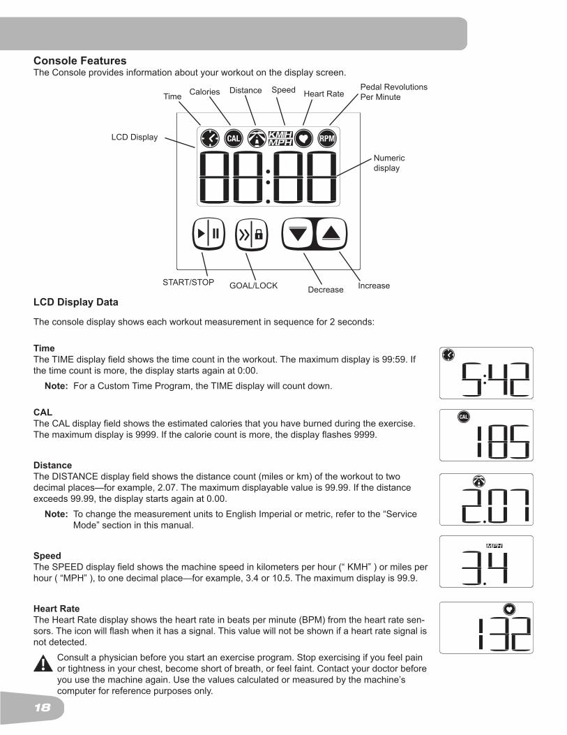
Console FeaturesThe Console provides information about your workout on the display screen.
LCD Display Data
Theconsoledisplayshowseachworkoutmeasurementinsequencefor2seconds:
TimeTheTIMEdisplayfieldshowsthetimecountintheworkout.Themaximumdisplayis99:59.Ifthetimecountismore,thedisplaystartsagainat0:00. Note: For a Custom Time Program, the TIME display will count down.
CALTheCALdisplayfieldshowstheestimatedcaloriesthatyouhaveburnedduringtheexercise.Themaximumdisplayis9999.Ifthecaloriecountismore,thedisplayflashes9999.
DistanceTheDISTANCEdisplayfieldshowsthedistancecount(milesorkm)oftheworkouttotwodecimalplaces—forexample,2.07.Themaximumdisplayablevalueis99.99.Ifthedistanceexceeds99.99,thedisplaystartsagainat0.00. Note: To change the measurement units to English Imperial or metric, refer to the “Service
Mode” section in this manual.
SpeedTheSPEEDdisplayfieldshowsthemachinespeedinkilometersperhour(“KMH”)ormilesperhour(“MPH”),toonedecimalplace—forexample,3.4or10.5.Themaximumdisplayis99.9.
Heart RateThe Heart Rate display shows the heart rate in beats per minute (BPM) from the heart rate sen-sors.Theiconwillflashwhenithasasignal.Thisvaluewillnotbeshownifaheartratesignalisnot detected.
Consultaphysicianbeforeyoustartanexerciseprogram.Stopexercisingifyoufeelpainor tightness in your chest, become short of breath, or feel faint. Contact your doctor before you use the machine again. Use the values calculated or measured by the machine’s computer for reference purposes only.
Time Calories Distance Speed Pedal RevolutionsPer Minute
Numeric display
LCD Display
Heart Rate
START/STOP GOAL/LOCK IncreaseDecrease

19
RPMTheRPMdisplayfieldshowsthemachinerevolutionsperminute(RPM).Themaximumdisplayis200.
Keypad FunctionsSTART/STOPbutton-StartsaProgramworkout,confirmsaselection,orresumesapausedworkout.Pausesanactiveworkout, ends a paused workout, or goes back to the previous screen.
GOAL/LOCKbutton-Pushtolockthescreenononeworkoutvalue,unlockalockedworkoutvaluescreen,selectacustom goal, and move through the Custom Goal options.
Decrease () button- Decreases a value (time, distance, or calories) or moves through options
Increase () button- Increases a value (time, distance, or calories) or moves through options
Contact Heart Rate SensorsContact Heart Rate (CHR) sensors send your heart rate signals to the Console. The CHR sensors are the stainless steel parts of the Handlebars. To use, put your hands comfortably around the sensors. Be sure that your hands touch both the topandthebottomofthesensors.Holdfirm,butnottootightorloose.Bothhandsmustmakecontactwiththesensorsfor the Console to detect a pulse. After the Console detects four stable pulse signals, your initial pulse rate will be shown.
OncetheConsolehasyourinitialheartrate,donotmoveorshiftyourhandsfor10to15seconds.TheConsolewillnowvalidatetheheartrate.Manyfactorsinfluencetheabilityofthesensorstodetectyourheartratesignal:
• Movement of the upper body muscles (including arms) produces an electrical signal (muscle artifact) that can interfere with pulse detection. Slight hand movement while in contact with the sensors can also produce interference.
• Hand lotion or calloused hands may act as an insulating layer to reduce the signal strength.• SomeElectrocardiogram(EKG)signalsgeneratedbyindividualsarenotstrongenoughtobedetectedbythesensors.• Theproximityofotherelectronicmachinescangenerateinterference.
Heart Rate CalculationsYourmaximumheartrateusuallydecreasesfrom220BeatsPerMinute(BPM)inchildhoodtoapproximately160BPMbyage60.Thisfallinheartrateisusuallylinear,decreasingbyapproximatelyoneBPMforeachyear.Thereisnoindicationthattraininginfluencesthedecreaseinmaximumheartrate.Individualsofthesameagecouldhavedifferentmaximumheartrates.Itismoreaccuratetofindthisvaluebycompletingastresstestthanbyusinganagerelatedformula.
Yourat-restheartrateisinfluencedbyendurancetraining.Thetypicaladulthasanat-restheartrateofapproximately72BPM, where as highly trained runners may have readings of 40 BPM or lower.
The Heart Rate table is an estimate of what Heart Rate Zone (HRZ) is effective to burn fat and improve your cardiovas-cular system. Physical conditions vary, therefore your individual HRZ could be several beats higher or lower than what is shown.
Themostefficientproceduretoburnfatduringexerciseistostartataslowpaceandgraduallyincreaseyourintensityun-tilyourheartratereachesbetween60–85%ofyourmaximumheartrate.Continueatthatpace,keepingyourheartratein that target zone for over 20 minutes. The longer you maintain your target heart rate, the more fat your body will burn.
The graph is a brief guideline, describing the generally suggested target heart rates based on age. As noted above, your

20
optimal target rate may be higher or lower. Consult your physician for your individual target heart rate zone.
Note:Aswithallexercisesandfitnessregimens,alwaysuseyourbestjudgmentwhenyouincreaseyourexercisetime or intensity.
20-24
FAT-BURNING TARGET HEART RATEH
eart
Rat
e B
PM (b
eats
per
min
ute)
Age
25-290
50
100
150
200
250
30-34 35-39 40-44 45-49 50-54 55-59 60-64 65-69 70+
196 191 186 181 176 171 166 161 156 151 146
167 162 158 154150
145 141 137 133 128126
Maximum Heart Rate
Target Heart Rate Zone(keep within this rangefor optimum fat-burning)
118 115 112 109 106 103 100 97 94 91 88

21
operaTIons
What to WearWearrubber-soledathleticshoes.Youwillneedtheappropriateclothesforexercisethatallowyoutomovefreely.
How Often Should You ExerciseConsultaphysicianbeforeyoustartanexerciseprogram.Stopexercisingifyoufeelpainortightnessinyourchest,become short of breath, or feel faint. Contact your doctor before you use the machine again. Use the values calcu-lated or measured by the machine’s computer for reference purposes only.
• 3 times a week for 20 minutes each day.• Schedule workouts in advance and try to follow the schedule.
Intensity of WorkoutToincreasetheintensityofyourworkout:• Push yourself to increase the number of Pedal revolutions per minute • Place your feet higher on the Pedals
Seat AdjustmentCorrectseatplacementencouragesexerciseefficiencyandcomfort,whilereducingtheriskofinjury.1. With a Pedal in the forward position, place the heel of your foot to the lowest part of it. Your
leg should be bent slightly at the knee.2. If your leg is too straight or your foot cannot touch the Pedal, move the seat forward. If your
leg is bent too much, move the seat toward the back.
Step off the machine before you adjust the seat.
3. Loosen and pull the adjustment knob on the seat tube. Adjust the seat to the desired height.4. Release the adjustment knob to engage the locking pin. Be sure that the pin is fully
engaged and fully tighten the knob.
Console AdjustmentAdjusting the Console may make it easier to view and reduce potential glare on it. 1. LoosentheConsoleAdjustmentKnobontheConsoleSupportBar.2. Adjust the Console to the desired position.3. TightentheConsoleAdjustmentKnob.
Mounting and Dismounting Your Machine
Care should be used when mounting or dismounting the machine.
Only mount and dismount from the left side of the machine.
Tomountyourfitnessmachine:1. From the left side of the machine, move the Pedals until the Left Pedal is furthest forward.
Be sure nothing is on the Rail Assemby when moving the Pedals.
2. While facing forward, step between the Pedals with your right foot.

22
3. Grasp the Static Handlebars behind you and lower yourself into the Seat Assembly.4. Place your foot on the Right Pedal and push it forward to bring the Left Pedal close to you. 5. PlaceyourotherfootontheLeftPedal.
Todismountyourfitnessmachine:1. Bring the machine to a complete stop.
This machine cannot stop the Pedals independently of the Resistance Fan. Reduce the pace of the Pedals to bring them and the Resistance Fan to a stop. Do not dismount the machine until the Pedals have come to a complete stop.
2. Move the Pedals until the Left Pedal is furthest forward.3. SwingyourleftfoottotheoutsideoftheLeftPedalandontothefloor.4. NowplaceyourrightfootontothefloorbetweenthePedals.5. GrasptheStaticHandlebarstosteadyyourself.6. Pivot yourself off of the machine, pushing up from the Static Handlebars if necessary. Release the Static Handlebars when stable and off of the machine.7. Step over the Left Pedal with your right leg.
Power-Up / Idle ModeThe Console will enter Power-Up / Idle Mode if any button is pushed, or if it receives a signal from the RPM sensor as a resultofpedalingthemachine.WheninIdleMode,theConsolewillshowazerovalueforeachdisplayfield.
Note: TheConsolewilldisplay“Lbat”ifthebatteriesarearound10%oftheirratedpowerduringpowerup.
Auto Shut-Off (Sleep Mode)IftheConsoledoesnotreceiveanyinputinapproximately5minutes,itwillautomaticallyshutoff.TheLCDdisplayisoffwhile in Sleep Mode. Note: The Console does not have an On/Off switch.
Quick Start ProgramThe Quick Start program lets you start a workout without entering any information.1. Sit on the machine.2. Push the START/STOP button to start the workout program.3. When done with your workout, stop pedaling and push START/STOP to pause the workout. To clear the workout
values and go back to Idle Mode, push and hold down START/STOP for 3 seconds.
Custom Goal ProgramsThe Console allows you to select a Custom Goal Program and enter your own workout value. The Console will remember this value until changed.1. Sit on the machine.2. FromtheIdleMode,pushtheGOAL/LOCKbutton.

23
3. The Console will display one of the Custom Goal Programs ( Time, Calorie or Distance ) by activating their display field.PushtheGOAL/LOCKbuttontomovethroughtheoptions.
Note: The Console will show the default value, or the last custom value, for each option. Thedefaultgoalvaluesare:Time=20minutes,Calories=100,Distance=5miles.
4. With your desired goal selected, push the Increase and Decrease buttons to adjust the custom goal value. 5. PushSTART/STOPtoacceptthecustomgoalvalue.YourCustomGoalWorkoutwillnowbegin.
Paused / Results ModeToPauseaworkout:1. Stop pedaling and push the START/STOP button to pause your workout. Note: TheConsolewillautomaticallypauseifthereisnoRPMsignalfor5seconds.
2. To continue your workout, push START/STOP or start pedaling.
Whenpaused,theworkoutvalueswillflashastheConsoledisplayseachvalue.YoucanusetheIncrease/Decreasebut-tons to move through the other workout values manually. To clear the workout values and go back to Idle Mode, push and hold down START/STOP for 3 seconds. The Console will makeanaudiblebeeptoconfirmtheaction.IftheConsoledoesnotreceiveanyinputinapproximately5minutes,itwillautomatically shut off.

24
Console serVICe mode
The Console Service Mode lets you set the units of measurement to either English or Metric, see the total distance and timethemachinehasbeenused,orfindoutwhichversionofFirmwareisinstalled.1. Hold down the Increase button and Decrease button together for 3 seconds while in the Idle Mode to go into the Con-
sole Service Mode.2. The Console display shows the Units prompt ( “Unit” ). Push START/STOP to start Units option. Push the Increase/
Decreasebuttonstochangebetween“MI/LbS”(ImperialEnglishunits)and“KM/Si”(metricunits).3. PushSTART/STOPtoset.Forthenextoption,pushtheIncreasebutton.4. The Console display shows the Workout Statistics prompt ( “Stat” ). Push START/STOP to start the Workout Statistics
option. Push the Increase/Decrease buttons to change between the Total Distance and Total Time values. Note: ThevalueforTotalDistancecanberesetbypushingandholdingtheGOAL/LOCKbuttonfor3seconds.5. PushSTART/STOPtoexit.Forthenextoption,pushtheIncreasebutton.6. The Console display shows the Firmware Version prompt ( “COdE” ). Push START/STOP. The Console will display
which Firmware Version is installed.7. PushSTART/STOPtoexit.
TofullyexittheConsoleServiceModefromaprompt,pushandholddowntheSTART/STOPbuttonfor3seconds.InServiceModeiftheConsoledoesnotreceiveanyinputforapproximately5minutes,itwillgointoSleepMode.

25
Read all maintenance instructions fully before you start any repair work. In some conditions, an assistant is required to do the necessary tasks.
Equipmentmustberegularlyexaminedfordamageandrepairs.Theownerisresponsibletomakesurethatregularmaintenance is done. Worn or damaged components must be repaired or replaced immediately. Only manufacturer supplied components can be used to maintain and repair the equipment.
To reduce the risk of electrical shock or unsupervised usage of the equipment, always remove the batter-iesfromthemachineandwait5minutesbeforecleaning,maintainingorrepairingthemachine.
Daily: Beforeeachuse,examinetheexercisemachineforloose,broken,damaged,orwornparts.Donotuseiffoundinthiscondition.Repairorreplaceallpartsatthefirstsignof wear or damage. After each workout, use a damp cloth to wipe your machine and Console free of sweat.Note:AvoidexcessivemoistureontheConsole.
Weekly: Check for smooth roller operation. Wipe the machine to remove dust, dirt, or grime. Clean the rails and surface of the rollers with a damp cloth. Vacuum the upper face of the Pedals to remove any foreign material.Note: Do not use petroleum based products.
Monthly or after 20 hours:
Make sure all bolts and screws are tight. Tighten as necessary.
NOTICE:Donotcleanwithapetroleumbasedsolventoranautomotivecleaner.BesuretokeeptheConsolefree of moisture.
maInTenanCe
26
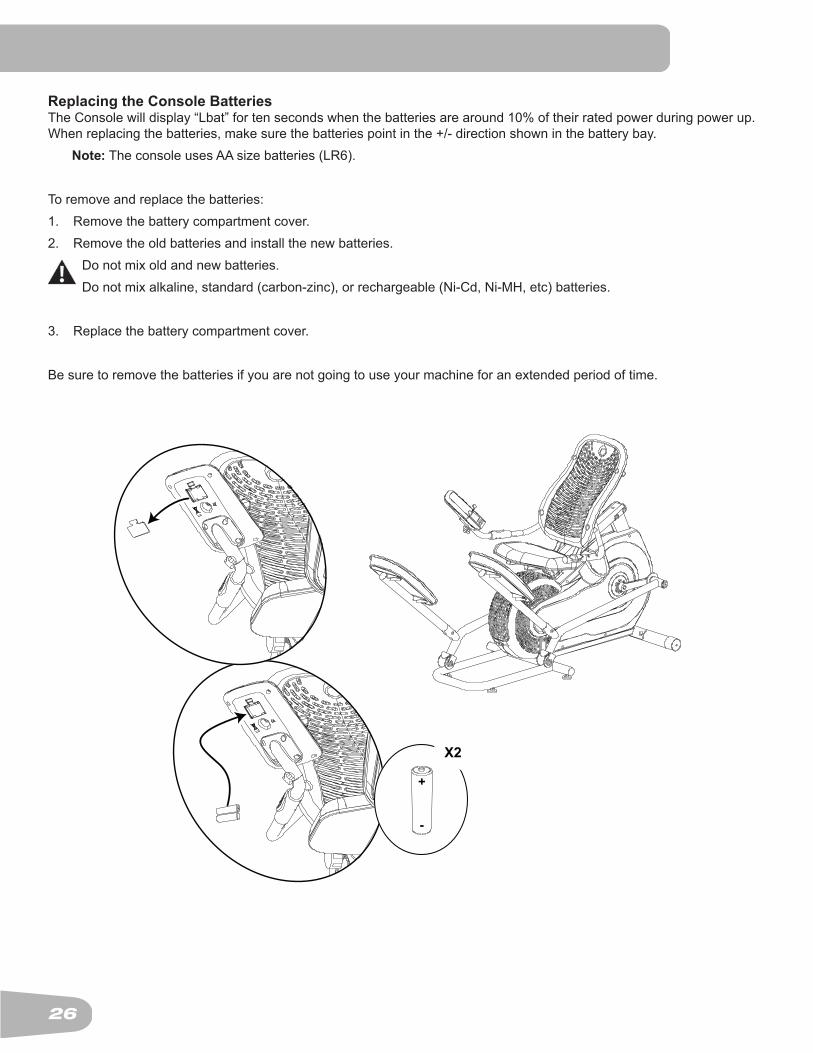
Replacing the Console BatteriesTheConsolewilldisplay“Lbat”fortensecondswhenthebatteriesarearound10%oftheirratedpowerduringpowerup.When replacing the batteries, make sure the batteries point in the +/- direction shown in the battery bay. Note: The console uses AA size batteries (LR6).
Toremoveandreplacethebatteries:1. Remove the battery compartment cover.2. Remove the old batteries and install the new batteries.
Donotmixoldandnewbatteries.Donotmixalkaline,standard(carbon-zinc),orrechargeable(Ni-Cd,Ni-MH,etc)batteries.
3. Replace the battery compartment cover.
Besuretoremovethebatteriesifyouarenotgoingtouseyourmachineforanextendedperiodoftime.

27
Maintenance Parts
A Pedal, Foot L Seat, Back W LevelerB Pedal Arm M Handlebar X Rail AssemblyC Roller N Seat, Bottom Y Speed Sensor MagnetD Leg, Right O Water Bottle Holder Z Speed SensorE Crank Arm, Right P Seat Support Bar AA Fan BladeF Shroud, Right Q Seat Assembly BB TensionerG Center Plate R SeatAdjustmentKnob CC Drive BeltH Fan Vent S Rear Stabilizer DD Drive PulleyI Seat Rail T Shroud, Left EE Console Cable, LowerJ Console Support Arm U Crank Arm, LeftK Console V Leg, Left
YZ
A
B
C
D EF
G
H
H
X
WW
I
S
K
J
L
M
N
P
O
QR
T
G
U
V
C
B
A
BB CC DDAA
EE

28
TroublesHooTIng
Condition/Problem Things to Check SolutionNo display/partial display/unit will not turn on
Batteries Make sure batteries are installed correctly. If batteries are cor-rectly installed, replace with a set of new batteries.
Check data cable integrity All wires in cable should be intact. If any are visibly crimped or cut, replace cable.
Check data cableconnections/orientation
Be sure cable is connected securely and oriented properly. Small latch on connector should line up and snap into place.
Check console display for damage
Check for visual sign that console display is cracked or other-wise damaged. Replace Console if damaged.
Console Display IfConsoleonlyhaspartialdisplayandallconnectionsarefine,replace the Console.If the above steps do not resolve the problem, contact Cus-tomer Care for further assistance.
Unit operates but Contact HR not displayed
HR cable connection at Console Support Arm and Handlebar
Be sure cables are connected securely.
Sensor grip Be sure hands are centered on HR sensors. Hands must be kept still with relatively equal pressure applied to each side.
Dry or calloused hands Sensorsmayhavedifficultywithdriedoutorcallousedhands.A conductive electrode cream such as “Signa Crème” or “Buh-Bump” can help make better conduct. These are available on theweboratmedicalorsomelargerfitnessstores.
Handlebar and Console Support Arm
If tests reveal no other issues, Handlebar and Console Support Arm should be replaced.
Console displays “Lbat” error code
Batteries Replace batteries
Speed displayed is not accurate
Display set to wrong unit of measure (English/Met-ric)
Console displays units.
Console displays “E2” er-ror code
Check data cable integrity All wires in cable should be intact. If any are cut or crimped, replace cable.
Check data cableconnections/orientation
Be sure cable is connected securely and oriented properly. Small latch on connector should line up and snap into place.
Console Electronics If tests reveal no other issues, Console should be replaced.No speed/RPM reading while pedaling, Console displays “Please Stride” error code
Check data cable integrity All wires in cable should be intact. If any are cut or crimped, replace cable.
Check data cableconnections/orientation
Be sure cable is connected securely and oriented properly. Small latch on connector should line up and snap into place.
Check magnet position (requires shroud removal)
Magnet should be in place on pulley.
Check Speed Sensor (re-quires shroud removal)
Speed sensor should be aligned with magnet and connected to data cable. Realign sensor if necessary. Replace if there is any damage to the sensor or the connecting wire.

29
Condition/Problem Things to Check SolutionConsole shuts off (enters sleep mode) while in use
Check data cable integrity All wires in the cable should be intact. If any are cut or crimped, replace cable.
Check data cableconnections/orientation
Be sure cable is connected securely and oriented properly. Small latch on connector should line up and snap into place.
Reset machine Remove batteries from unit for 3 minutes. Reinstall batteries and start Console.
Check the position of Speed Sensor Magnet (requires shroud removal)
Speed Sensor Magnet should be in place on pulley.
Check Speed Sensor Contact Customer Care for further assistance.Unit rocks/does not sit level
Check leveler adjustment Adjust levelers until machine is level.
Check surface under unit Adjustmentmaynotbeabletocompensateforextremelyun-even surfaces. Move machine to level area.
Foot pedals loose/unit dif-ficulttooperate
Hardware Tightly secure all hardware on the Pedal Legs.
Clicking sound when operating
Check pedal leg to crank arm connection
Remove pedal legs and reattach.

30

31
WarranTy
Who Is CoveredThis warranty is valid only to the original purchaser and is not transferable or applicable to any other person(s).
What Is CoveredNautilus, Inc. warrants that this product is free from defects in materials and workmanship, when used for the purpose intended, under normal conditions, and provided it receives proper care and maintenance as described in the Product’s Assembly and Owner’s manual. This warranty is good only for authentic, original, legitimate machines manufactured by Nautilus, Inc. and sold through an authorized agent and used in the United States or Canada.
Terms• Frame 5years• Mechanical parts 1 year• Electronics 1 year• Wearitems 90days• Labor 90days (Labor support does not include the installation of replacement parts involved in the initial product assembly and preventative maintenance services.)
How Nautilus Will Support the WarrantyThroughout the terms of the warranty coverage, Nautilus, Inc. will repair any machine that proves to be defective in materials or workmanship. Nautilus reserves the right to replace the product in the event a repair is not possible. When Nautilus determines replacement is the correct remedy, Nautilus may apply a limited credit reimbursement toward another Nautilus, Inc. brand Product, at our discretion. This reimbursement may be prorated based on length of ownership. Nautilus, Inc. provides repair service within major metropolitan areas. Nautilus, Inc. reserves the right to charge the consumer for travel outside these areas. Nautilus, Inc. is not responsible for dealer labor or maintenance charges beyond the applicable warranty period(s) stated herein. Nautilus, Inc. reserves the right to substitute material, parts or products of equal or better quality if identical materials or products are not available at the time of service under this warranty. Any replacement of theproductunderthetermsoftheWarrantyinnowayextendstheoriginalWarrantyperiod.Anylimitedcreditreimbursementmaybeproratedbasedonlengthofownership. THESE REMEDIES ARE THE EXCLUSIVE AND SOLE REMEDIES FOR ANY BREACH OF WARRANTY.
What You Must Do• Retain appropriate and acceptable Proof of Purchase.• Operate,maintain,andinspecttheProductasspecifiedintheProductDocumentation(Manuals,(Assembly,Owner’sManuals,etc.).• Productmustbeusedexclusivelyforthepurposeintended.• Notify Nautilus within 30 days after detecting an issue with the Product.• Install replacement parts or components in accordance with any Nautilus instructions.• Perform diagnostic procedures with a trained Nautilus, Inc representative if requested.
What Is Not Covered• Damageduetoabuse,tamperingormodificationoftheProduct,failuretoproperlyfollowassemblyinstructions,maintenanceinstructions,orsafetywarnings
as stated in the Product Documentation (Assembly, Owner’s Manuals, etc), damage due to improper storage or the effect of environmental conditions such as moisture or weather, misuse, mishandling, accident, natural disasters, power surges.
• Amachineplacedorusedinacommercialorinstitutionalsetting.Thisincludesgyms,corporations,workplaces,clubs,fitnesscentersandanypublicorprivateentitythathasamachineforusebyitsmembers,customers,employeesoraffiliates.
• DamagecausedbyexceedingmaximumuserweightsasdefinedintheProduct’sOwner’smanualorwarninglabel.• Damage due to normal usage and wear and tear.• ThiswarrantydoesnotextendtoanyterritoriesorcountriesoutsidetheUnitedStatesandCanada.
How to Obtain ServiceForProductspurchaseddirectlyfromNautilus,Inc.contacttheNautilusofficelistedontheContactspageoftheproductsOwner’smanual.Youmayberequiredtoreturnthedefectivecomponenttoaspecifiedaddressforrepairorinspection,atyourexpense.Standardgroundshippingofanywarrantyreplacementpartswillbe paid by Nautilus, Inc. For products purchased from a retailer, you may be asked to contact your retailer for warranty support.
ExclusionsTheprecedingwarrantiesarethesoleandexclusiveexpresswarrantiesmadebyNautilus,Inc.Theysupersedeanyprior,contraryoradditionalrepresentations,whether oral or written. No agent, representative, dealer, person or employee has the authority to alter or increase the obligations or limitations of this warranty. Any implied warranties, including the WARRANTY OF MERCHANTABILITY and any WARRANTY OF FITNESS FOR A PARTICULAR PURPOSE, are limited in durationtothetermoftheapplicableexpresswarrantyprovidedabove,whicheverislonger.Somestatesdonotallowlimitationsonhowlonganimpliedwarrantylasts, so the above limitation may not apply to you.
Limitation of RemediesEXCEPT AS OTHERWISE REQUIRED BY APPLICABLE LAW, THE PURCHASER’S EXCLUSIVE REMEDY IS LIMITED TO REPAIR OR REPLACEMENT OF ANY COMPONENT DEEMED BY NAUTILUS, INC. TO BE DEFECTIVE UNDER THE TERMS AND CONDITIONS STATED HEREIN. IN NO EVENT WILL NAUTILUS, INC. BE LIABLE FOR ANY SPECIAL, CONSEQUENTIAL, INCIDENTAL, INDIRECT OR ECONOMIC DAMAGES, REGARDLESS OF THE THEORY OF LIABILITY (INCLUDING, WITHOUT LIMITATION, PRODUCT LIABILITY, NEGLIGENCE OR OTHER TORT) OR FOR ANY LOST REVENUE, PROFIT, DATA, PRIVACY OR FOR ANY PUNITIVE DAMAGES ARISING OUT OF OR RELATED TO THE USE OF THE FITNESS MACHINE EVEN IF NAUTILUS, INC. HAS BEEN ADVISED OF THE POSSIBILITY OF SUCH DAMAGES. THIS EXCLUSION AND LIMITATION SHALL APPLY EVEN IF ANY REMEDY FAILS OF ITS ESSENTIAL PURPOSE. SOME STATES DO NOT ALLOW THE EXCLUSION OR LIMITATION OF CONSEQUENTIAL OR INCIDENTAL TYPE DAMAGES SO THE ABOVE LIMITATION MAY NOT APPLY TO YOU.
State LawsThiswarrantygivesyouspecificlegalrights.Youmayalsohaveotherrights,whichvaryfromstatetostate.
ExpirationsIfthewarrantyhasexpired,Nautilus,Inc.mayassistwithreplacementsorrepairstopartsandlabor,buttherewillbeachargefortheseservices.ContactaNautilus®officeforinformationonpost-warrantypartsandservices.Nautilus®doesnotguaranteeavailabilityofsparepartsafterexpirationofwarrantyperiod.
International PurchasesIf you purchased your machine outside of the United States consult your local distributor or dealer for warranty coverage.

Nautilus® Bowflex® Schwinn® Fitness Universal®
004-4723.120112.C
EN