scenic regional library district branch library...
TRANSCRIPT
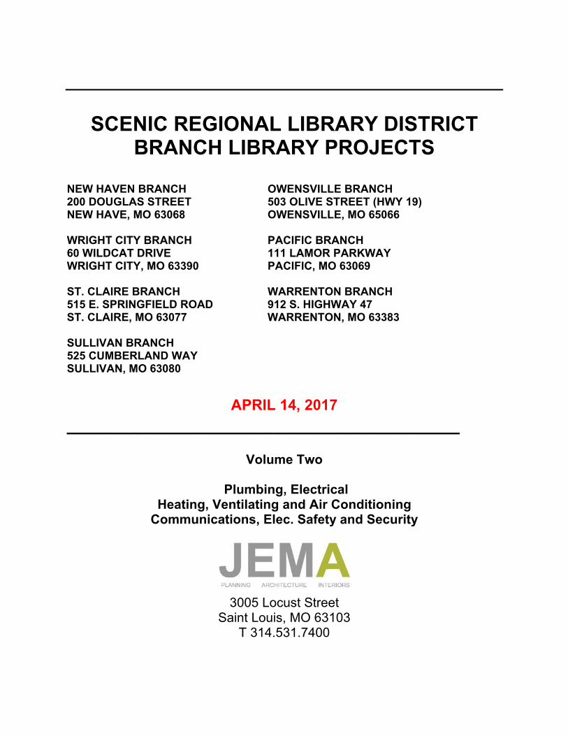
SCENIC REGIONAL LIBRARY DISTRICT BRANCH LIBRARY PROJECTS
NEW HAVEN BRANCH OWENSVILLE BRANCH 200 DOUGLAS STREET 503 OLIVE STREET (HWY 19) NEW HAVE, MO 63068 OWENSVILLE, MO 65066 WRIGHT CITY BRANCH PACIFIC BRANCH 60 WILDCAT DRIVE 111 LAMOR PARKWAY WRIGHT CITY, MO 63390 PACIFIC, MO 63069 ST. CLAIRE BRANCH WARRENTON BRANCH 515 E. SPRINGFIELD ROAD 912 S. HIGHWAY 47 ST. CLAIRE, MO 63077 WARRENTON, MO 63383 SULLIVAN BRANCH 525 CUMBERLAND WAY SULLIVAN, MO 63080
APRIL 14, 2017
______________________________________
Volume Two
Plumbing, Electrical Heating, Ventilating and Air Conditioning
Communications, Elec. Safety and Security
3005 Locust Street
Saint Louis, MO 63103 T 314.531.7400
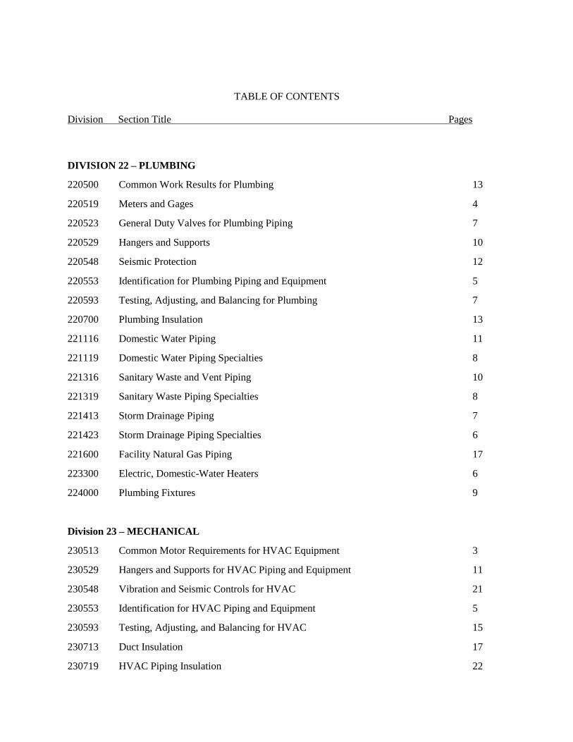
TABLE OF CONTENTS
Division Section Title Pages
DIVISION 22 – PLUMBING
220500 Common Work Results for Plumbing 13
220519 Meters and Gages 4
220523 General Duty Valves for Plumbing Piping 7
220529 Hangers and Supports 10
220548 Seismic Protection 12
220553 Identification for Plumbing Piping and Equipment 5
220593 Testing, Adjusting, and Balancing for Plumbing 7
220700 Plumbing Insulation 13
221116 Domestic Water Piping 11
221119 Domestic Water Piping Specialties 8
221316 Sanitary Waste and Vent Piping 10
221319 Sanitary Waste Piping Specialties 8
221413 Storm Drainage Piping 7
221423 Storm Drainage Piping Specialties 6
221600 Facility Natural Gas Piping 17
223300 Electric, Domestic-Water Heaters 6
224000 Plumbing Fixtures 9
Division 23 – MECHANICAL
230513 Common Motor Requirements for HVAC Equipment 3
230529 Hangers and Supports for HVAC Piping and Equipment 11
230548 Vibration and Seismic Controls for HVAC 21
230553 Identification for HVAC Piping and Equipment 5
230593 Testing, Adjusting, and Balancing for HVAC 15
230713 Duct Insulation 17
230719 HVAC Piping Insulation 22
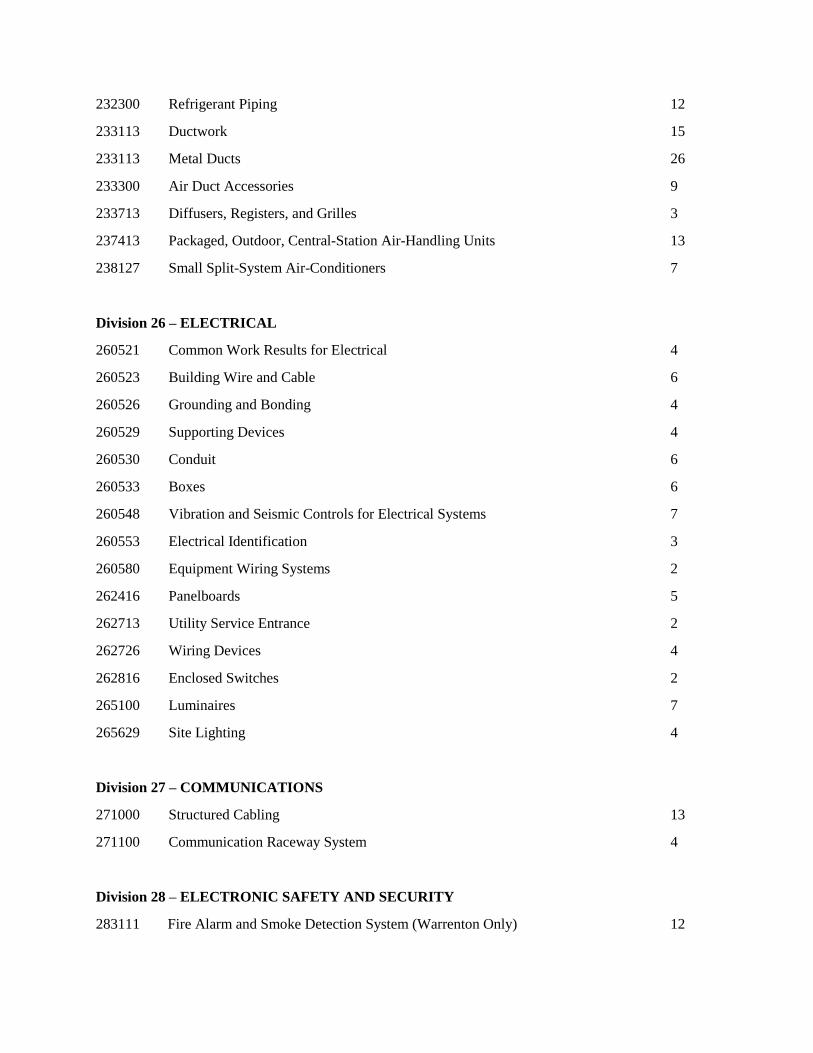
232300 Refrigerant Piping 12
233113 Ductwork 15
233113 Metal Ducts 26
233300 Air Duct Accessories 9
233713 Diffusers, Registers, and Grilles 3
237413 Packaged, Outdoor, Central-Station Air-Handling Units 13
238127 Small Split-System Air-Conditioners 7
Division 26 – ELECTRICAL
260521 Common Work Results for Electrical 4
260523 Building Wire and Cable 6
260526 Grounding and Bonding 4
260529 Supporting Devices 4
260530 Conduit 6
260533 Boxes 6
260548 Vibration and Seismic Controls for Electrical Systems 7
260553 Electrical Identification 3
260580 Equipment Wiring Systems 2
262416 Panelboards 5
262713 Utility Service Entrance 2
262726 Wiring Devices 4
262816 Enclosed Switches 2
265100 Luminaires 7
265629 Site Lighting 4
Division 27 – COMMUNICATIONS
271000 Structured Cabling 13
271100 Communication Raceway System 4
Division 28 – ELECTRONIC SAFETY AND SECURITY
283111 Fire Alarm and Smoke Detection System (Warrenton Only) 12
April 14, 2017 Scenic Regional Library District
16-1161.00 Branch Library Projects
COMMON WORK RESULTS FOR PLUMBING 22 0500 - 1
SECTION 22 0500 - COMMON WORK RESULTS FOR PLUMBING
ALL LIBRARIES
PART 1 - GENERAL
1.1 RELATED DOCUMENTS
A. Drawings and general provisions of the Contract, including General and Supplementary
Conditions and Division 01 Specification Sections, apply to this Section.
1.2 SUMMARY
A. This Section includes the following:
1. Piping materials and installation instructions common to most piping systems.
2. Transition fittings.
3. Dielectric fittings.
4. Mechanical sleeve seals.
5. Sleeves.
6. Wall Penetration Systems.
7. Escutcheons.
8. Grout.
9. Equipment installation requirements common to equipment sections.
10. Painting and finishing.
11. Concrete bases.
12. Supports and anchorages.
1.3 DEFINITIONS
A. Finished Spaces: Spaces other than mechanical and electrical equipment rooms, furred spaces,
pipe chases, unheated spaces immediately below roof, spaces above ceilings, unexcavated
spaces, crawlspaces, and tunnels.
B. Exposed, Interior Installations: Exposed to view indoors. Examples include finished occupied
spaces and mechanical equipment rooms.
C. Exposed, Exterior Installations: Exposed to view outdoors or subject to outdoor ambient
temperatures and weather conditions. Examples include rooftop locations.
D. Concealed, Interior Installations: Concealed from view and protected from physical contact by
building occupants. Examples include above ceilings and in chases.
E. Concealed, Exterior Installations: Concealed from view and protected from weather conditions
and physical contact by building occupants but subject to outdoor ambient temperatures.
Examples include installations within unheated shelters.
F. The following are industry abbreviations for plastic materials:
1. ABS: Acrylonitrile-butadiene-styrene plastic.
April 14, 2017 Scenic Regional Library District
16-1161.00 Branch Library Projects
COMMON WORK RESULTS FOR PLUMBING 22 0500 - 2
2. CPVC: Chlorinated polyvinyl chloride plastic.
3. PE: Polyethylene plastic.
4. PVC: Polyvinyl chloride plastic.
5. PP: Polypropylene
G. The following are industry abbreviations for rubber materials:
1. EPDM: Ethylene-propylene-diene terpolymer rubber.
2. NBR: Acrylonitrile-butadiene rubber.
1.4 SUBMITTALS
A. Product Data: For the following:
1. Transition fittings.
2. Dielectric fittings.
3. Mechanical sleeve seals.
4. Escutcheons.
B. Welding certificates.
1.5 CLOSEOUT SUBMITTALS
A. Record Drawings: Comply with Division 01 and the following:
1. Final Submittal:
a. Submit record digital data files and two set(s) of record digital data file plots.
b. Plot each drawing file, whether or not changes and additional information were
recorded.
1.6 QUALITY ASSURANCE
A. Steel Support Welding: Qualify processes and operators according to AWS D1.1, "Structural
Welding Code--Steel."
B. Steel Pipe Welding: Qualify processes and operators according to ASME Boiler and Pressure
Vessel Code: Section IX, "Welding and Brazing Qualifications."
1. Comply with provisions in ASME B31 Series, "Code for Pressure Piping."
2. Certify that each welder has passed AWS qualification tests for welding processes
involved and that certification is current.
C. Electrical Characteristics for Plumbing Equipment: Equipment of higher electrical
characteristics may be furnished provided such proposed equipment is approved in writing and
connecting electrical services, circuit breakers, and conduit sizes are appropriately modified. If
minimum energy ratings or efficiencies are specified, equipment shall comply with
requirements.
1.7 DELIVERY, STORAGE, AND HANDLING
April 14, 2017 Scenic Regional Library District
16-1161.00 Branch Library Projects
COMMON WORK RESULTS FOR PLUMBING 22 0500 - 3
A. Deliver pipes and tubes with factory-applied end caps. Maintain end caps through shipping,
storage, and handling to prevent pipe end damage and to prevent entrance of dirt, debris, and
moisture.
B. Store plastic pipes protected from direct sunlight. Support to prevent sagging and bending.
1.8 COORDINATION
A. Arrange for pipe spaces, chases, slots, and openings in building structure during progress of
construction, to allow for plumbing installations.
B. Coordinate installation of required supporting devices and set sleeves in poured-in-place
concrete and other structural components as they are constructed.
C. Coordinate requirements for access panels and doors for plumbing items requiring access that
are concealed behind finished surfaces. Access panels and doors are specified in Division 08
Section "Access Doors and Frames."
PART 2 - PRODUCTS
2.1 MANUFACTURERS
A. In other Part 2 articles where subparagraph titles below introduce lists, the following
requirements apply for product selection:
1. Manufacturers: Subject to compliance with requirements, provide products by the
manufacturers specified.
2.2 PIPE, TUBE, AND FITTINGS
A. Refer to individual Division 22 piping Sections for pipe, tube, and fitting materials and joining
methods.
B. Pipe Threads: ASME B1.20.1 for factory-threaded pipe and pipe fittings.
2.3 JOINING MATERIALS
A. Refer to individual Division 22 piping Sections for special joining materials not listed below.
B. Pipe-Flange Gasket Materials: Suitable for chemical and thermal conditions of piping system
contents.
1. ASME B16.21, nonmetallic, flat, asbestos-free, 1/8-inch maximum thickness unless
thickness or specific material is indicated.
a. Full-Face Type: For flat-face, Class 125, cast-iron and cast-bronze flanges.
b. Narrow-Face Type: For raised-face, Class 250, cast-iron and steel flanges.
2. AWWA C110, rubber, flat face, 1/8 inch thick, unless otherwise indicated; and full-face
or ring type, unless otherwise indicated.
April 14, 2017 Scenic Regional Library District
16-1161.00 Branch Library Projects
COMMON WORK RESULTS FOR PLUMBING 22 0500 - 4
C. Flange Bolts and Nuts: ASME B18.2.1, carbon steel, unless otherwise indicated.
D. Plastic, Pipe-Flange Gasket, Bolts, and Nuts: Type and material recommended by piping
system manufacturer, unless otherwise indicated.
E. Solder Filler Metals: ASTM B 32, lead-free alloys. Include water-flushable flux according to
ASTM B 813.
F. Brazing Filler Metals: AWS A5.8, BCuP Series, copper-phosphorus alloys for general-duty
brazing, unless otherwise indicated; and AWS A5.8, BAg1, silver alloy for refrigerant piping,
unless otherwise indicated.
G. Welding Filler Metals: Comply with AWS D10.12 for welding materials appropriate for wall
thickness and chemical analysis of steel pipe being welded.
H. Solvent Cements for Joining Plastic Piping:
1. PVC Piping: ASTM D 2564, medium body, medium set. Include purple primer
according to ASTM F 656. Note: Clear primer will not be allowed.
I. Fiberglass Pipe Adhesive: As furnished or recommended by pipe manufacturer.
J. Polypropylene pipe: Heat fusion as recommended by manufacturer.
2.4 TRANSITION FITTINGS
A. AWWA Transition Couplings: Same size as, and with pressure rating at least equal to and with
ends compatible with, piping to be joined.
1. Manufacturers:
a. Cascade Waterworks Mfg. Co.
b. Dresser Industries, Inc.; DMD Div.
c. Ford Meter Box Company, Incorporated (The); Pipe Products Div.
d. Viking Johnson.
2. Underground Piping NPS 1-1/2 and Smaller: Manufactured fitting or coupling.
3. Underground Piping NPS 2 and Larger: AWWA C219, metal sleeve-type coupling.
4. Aboveground Pressure Piping: Pipe fitting.
B. Flexible Transition Couplings for Underground Nonpressure Drainage Piping: ASTM C 1173
with elastomeric sleeve, ends same size as piping to be joined, and corrosion-resistant metal
band on each end.
1. Manufacturers:
a. Cascade Waterworks Mfg. Co.
b. Mission Rubber Company.
c. Plastic Oddities, Inc.
C. Plastic-to-Metal Transition Fittings:
April 14, 2017 Scenic Regional Library District
16-1161.00 Branch Library Projects
COMMON WORK RESULTS FOR PLUMBING 22 0500 - 5
1. Manufacturers: Subject to compliance with requirements, available manufacturers
offering products that may be incorporated into the Work include:
2. Basis-of-Design Product: Subject to compliance with requirements, provide product
indicated on drawings or comparable product by one of the following:
a. Charlotte Pipe and Foundry Company.
b. Harvel Plastics, Inc.
3. Description:
a. One-piece fitting with manufacturer’s Schedule 80 equivalent dimensions.
b. One end with threaded brass insert and one socket end.
2.5 DIELECTRIC FITTINGS
A. Description: Combination fitting of copper alloy and ferrous materials with threaded, solder-
joint, plain, or weld-neck end connections that match piping system materials.
B. Insulating Material: Suitable for system fluid, pressure, and temperature.
C. Dielectric Unions: Factory-fabricated, union assembly, for 250-psig minimum working
pressure at 180 deg F.
1. Manufacturers:
a. Capitol Manufacturing Company.
b. Central Plastics Company.
c. EPCO Sales, Inc.
d. Hart Industries International, Inc.
e. Watts Regulator Co.; a division of Watts Water Technologies, Inc.
f. Zurn Plumbing Products Group; Wilkins Water Control Products.
D. Dielectric Flanges: Factory-fabricated, companion-flange assembly, for 150- or 300-psig
minimum working pressure as required to suit system pressures.
1. Manufacturers:
a. Capitol Manufacturing Co.
b. Central Plastics Company.
c. Epco Sales, Inc.
d. Watts Industries, Inc.; Water Products Div.
E. Dielectric-Flange Kits: Companion-flange assembly for field assembly. Include flanges, full-
face- or ring-type neoprene or phenolic gasket, phenolic or polyethylene bolt sleeves, phenolic
washers, and steel backing washers.
1. Manufacturers:
a. Advance Products & Systems, Inc.
b. Calpico, Inc.
c. Pipeline Seal and Insulator, Inc.
d. Central Plastics Company.
April 14, 2017 Scenic Regional Library District
16-1161.00 Branch Library Projects
COMMON WORK RESULTS FOR PLUMBING 22 0500 - 6
2. Separate companion flanges and steel bolts and nuts shall have 150- or 300-psig
minimum working pressure where required to suit system pressures.
F. Dielectric Couplings: Galvanized-steel coupling with inert and noncorrosive, thermoplastic
lining; threaded ends; and 300-psig minimum working pressure at 225 deg F.
1. Manufacturers:
a. Calpico, Inc.
b. Lochinvar Corp.
G. Dielectric Nipples: Electroplated steel nipple with inert and noncorrosive, thermoplastic lining;
plain, threaded, or grooved ends; and 300-psig minimum working pressure at 225 deg F.
1. Manufacturers:
a. Perfection Corp.
b. Precision Plumbing Products, Inc.
c. Sioux Chief Manufacturing Co., Inc.
d. Victaulic Co. of America.
2.6 MECHANICAL SLEEVE SEALS
A. Description: Modular sealing element unit, designed for field assembly, to fill annular space
between pipe and sleeve.
1. Manufacturers:
a. Advance Products & Systems, Inc.
b. Calpico, Inc.
c. Metraflex Co.
d. Pipeline Seal and Insulator, Inc.
2. Sealing Elements: EPDM interlocking links shaped to fit surface of pipe. Include type
and number required for pipe material and size of pipe.
3. Pressure Plates: Stainless steel. Include two for each sealing element.
4. Connecting Bolts and Nuts: Stainless steel of length required to secure pressure plates to
sealing elements. Include one for each sealing element.
2.7 SLEEVES
A. Galvanized-Steel Sheet: 0.0239-inch minimum thickness; round tube closed with welded
longitudinal joint.
B. Galvanized Steel Pipe: ASTM A53/A 53M, Type E, Grade B, Schedule 40, zinc-coated, with
plain ends.
C. Steel Pipe: ASTM A 53, Type E, Grade B, Schedule 40, galvanized, plain ends.
D. Cast Iron: Cast or fabricated "wall pipe" equivalent to ductile-iron pressure pipe, with plain
ends and integral waterstop, unless otherwise indicated.
April 14, 2017 Scenic Regional Library District
16-1161.00 Branch Library Projects
COMMON WORK RESULTS FOR PLUMBING 22 0500 - 7
E. Stack Sleeve Fittings: Manufactured, cast-iron sleeve with integral clamping flange. Include
clamping ring and bolts and nuts for membrane flashing.
1. Underdeck Clamp: Clamping ring with set screws.
F. Molded PVC: Permanent, with nailing flange for attaching to wooden forms.
G. PVC Pipe: ASTM D 1785, Schedule 40.
2.8 WALL PENETRATION SYSTEMS
A. Manufacturers: Subject to compliance with requirements, provide products by one of the
following:
1. SIGMA.
B. Description: Wall-sleeve assembly, consisting of housing and gland, gaskets, and pipe sleeve.
1. Carrier-Pipe Deflection: Up to 5 percent without leakage.
2. Housing: Ductile-iron casting with hub, waterstop, anchor ring, and locking devices.
Include gland, bolts, and nuts.
3. Housing-to-Sleeve Gasket: EPDM rubber.
4. Housing-to-Carrier-Pipe Gasket: AWWA C111, EPDM rubber.
5. Pipe Sleeve: AWWA C151, ductile-iron pipe.
2.9 ESCUTCHEONS
A. Description: Manufactured wall and ceiling escutcheons and floor plates, with an ID to closely
fit around pipe, tube, and insulation of insulated piping and an OD that completely covers
opening.
B. One-Piece, Deep-Pattern Type: Deep-drawn, box-shaped brass with polished chrome-plated
finish.
C. One-Piece, Floor-Plate Type: Cast-iron floor plate.
D. Split-Casting, Floor-Plate Type: Cast brass with concealed hinge and set screw.
2.10 GROUT
A. Description: ASTM C 1107, Grade B, non-shrink and nonmetallic, dry hydraulic-cement grout.
1. Characteristics: Post-hardening, volume-adjusting, non-staining, noncorrosive,
nongaseous, and recommended for interior and exterior applications.
2. Design Mix: 5000-psi, 28-day compressive strength.
3. Packaging: Premixed and factory packaged.
PART 3 - EXECUTION
3.1 PIPING SYSTEMS - COMMON REQUIREMENTS
A. Install piping according to the following requirements and Division 22 Sections specifying
April 14, 2017 Scenic Regional Library District
16-1161.00 Branch Library Projects
COMMON WORK RESULTS FOR PLUMBING 22 0500 - 8
piping systems.
B. Drawing plans, schematics, and diagrams indicate general location and arrangement of piping
systems. Indicated locations and arrangements were used to size pipe and calculate friction
loss, expansion, pump sizing, and other design considerations. Install piping as indicated unless
deviations to layout are approved on Coordination Drawings.
C. Install piping in concealed locations, unless otherwise indicated and except in equipment rooms
and service areas.
D. Install piping indicated to be exposed and piping in equipment rooms and service areas at right
angles or parallel to building walls. Diagonal runs are prohibited unless specifically indicated
otherwise.
E. Install piping above accessible ceilings to allow sufficient space for ceiling panel removal.
F. Install piping to permit valve servicing.
G. Install piping at indicated slopes.
H. Install piping free of sags and bends.
I. Install fittings for changes in direction and branch connections.
J. Install piping to allow application of insulation.
K. Select system components with pressure rating equal to or greater than system operating
pressure.
L. Install escutcheons for penetrations of walls, ceilings, and floors according to the following:
1. New Piping:
a. Piping with Fitting or Sleeve Protruding from Wall: One-piece, deep-pattern type.
b. Chrome-Plated Piping: One-piece, cast-brass type with polished chrome-plated
finish.
c. Insulated Piping: One-piece, stamped-steel type with spring clips.
d. Bare Piping at Wall and Floor Penetrations in Finished Spaces: One-piece, cast-
brass type with polished chrome-plated finish.
e. Bare Piping in Unfinished Service Spaces: One-piece, cast-brass type with rough-
brass finish.
f. Bare Piping in Equipment Rooms: One-piece, cast-brass type.
g. Bare Piping at Floor Penetrations in Equipment Rooms: One-piece, floor-plate
type.
M. Sleeves are not required for core-drilled holes.
N. Permanent sleeves are not required for holes formed by removable PE sleeves.
O. Install sleeves for pipes passing through concrete and masonry walls and concrete floor and roof
slabs.
April 14, 2017 Scenic Regional Library District
16-1161.00 Branch Library Projects
COMMON WORK RESULTS FOR PLUMBING 22 0500 - 9
P. Install sleeves for pipes passing through concrete and masonry walls, gypsum-board partitions,
and concrete floor and roof slabs.
1. Cut sleeves to length for mounting flush with both surfaces.
a. Exception: Extend sleeves installed in floors of mechanical equipment areas,
bottoms of shafts, and other wet areas 2 inches above finished floor level. Extend
cast-iron sleeve fittings below floor slab as required to secure clamping ring if ring
is specified.
2. Install sleeves in new walls and slabs as new walls and slabs are constructed.
3. Install sleeves that are large enough to provide 1/4-inch annular clear space between
sleeve and pipe or pipe insulation. Use the following sleeve materials:
a. PVC Pipe Sleeves: For pipes smaller than NPS 6.
b. Steel Sheet Sleeves: For pipes NPS 6 and larger, penetrating gypsum-board
partitions.
c. Stack Sleeve Fittings: For pipes penetrating floors with membrane waterproofing.
Secure flashing between clamping flanges. Install section of cast-iron soil pipe to
extend sleeve to 2 inches above finished floor level. Refer to Division 07 Section
"Sheet Metal Flashing and Trim" for flashing.
1) Seal space outside of sleeve fittings with grout.
4. Except for underground wall penetrations, seal annular space between sleeve and pipe or
pipe insulation, using joint sealants appropriate for size, depth, and location of joint.
Refer to Division 07 Section "Joint Sealants" for materials and installation.
Q. Aboveground, Exterior-Wall Pipe Penetrations: Seal penetrations using sleeves. Select sleeve
size to allow for 1-inch annular clear space between pipe and sleeve for installing mechanical
sleeve seals.
1. Install steel pipe for sleeves smaller than 6 inches in diameter.
2. Install cast-iron "wall pipes" for sleeves 6 inches and larger in diameter.
R. Underground, Exterior-Wall Pipe Penetrations: Install cast-iron "wall pipes" for sleeves. Seal
pipe penetrations using mechanical sleeve seals. Select sleeve size to allow for 1-inch annular
clear space between pipe and sleeve for installing mechanical sleeve seals.
1. Mechanical Sleeve Seal Installation: Select type and number of sealing elements
required for pipe material and size. Position pipe in center of sleeve. Assemble
mechanical sleeve seals and install in annular space between pipe and sleeve. Tighten
bolts against pressure plates that cause sealing elements to expand and make watertight
seal.
S. Fire-Barrier Penetrations: Maintain indicated fire rating of walls, partitions, ceilings, and floors
at pipe penetrations. Seal pipe penetrations with firestop materials. Refer to Division 07
Section "Penetration Firestopping" for materials.
T. Install sleeve seals in sleeves in exterior concrete walls at water-service piping entries into
building below grade.
April 14, 2017 Scenic Regional Library District
16-1161.00 Branch Library Projects
COMMON WORK RESULTS FOR PLUMBING 22 0500 - 10
U. Select type and number of sealing elements required for pipe material and size. Position pipe in
center of sleeve. Assemble sleeve seal components and install in annular space between pipe
and sleeve. Tighten bolts against pressure plates that cause sealing elements to expand and
make watertight seal.
V. Install wall penetration systems in new, exterior concrete walls.
W. Assemble wall penetration system components with sleeve pipe. Install so that end of sleeve
pipe and face of housing are flush with wall. Adjust locking devices to secure sleeve pipe in
housing.
X. Verify final equipment locations for roughing-in.
Y. Refer to equipment specifications in other Sections of these Specifications for roughing-in
requirements.
3.2 PIPING JOINT CONSTRUCTION
A. Join pipe and fittings according to the following requirements and Division 22 Sections
specifying piping systems.
B. Ream ends of pipes and tubes and remove burrs. Bevel plain ends of steel pipe.
C. Remove scale, slag, dirt, and debris from inside and outside of pipe and fittings before
assembly.
D. Soldered Joints: Apply ASTM B 813, water-flushable flux, unless otherwise indicated, to tube
end. Construct joints according to ASTM B 828 or CDA's "Copper Tube Handbook," using
lead-free solder alloy complying with ASTM B 32.
E. Brazed Joints: Construct joints according to AWS's "Brazing Handbook," "Pipe and Tube"
Chapter, using copper-phosphorus brazing filler metal complying with AWS A5.8.
F. Threaded Joints: Thread pipe with tapered pipe threads according to ASME B1.20.1. Cut
threads full and clean using sharp dies. Ream threaded pipe ends to remove burrs and restore
full ID. Join pipe fittings and valves as follows:
1. Apply appropriate tape or thread compound to external pipe threads unless dry seal
threading is specified.
2. Damaged Threads: Do not use pipe or pipe fittings with threads that are corroded or
damaged. Do not use pipe sections that have cracked or open welds.
G. Welded Joints: Construct joints according to AWS D10.12, using qualified processes and
welding operators according to Part 1 "Quality Assurance" Article.
H. Flanged Joints: Select appropriate gasket material, size, type, and thickness for service
application. Install gasket concentrically positioned. Use suitable lubricants on bolt threads.
I. Plastic Piping Solvent-Cement Joints: Clean and dry joining surfaces. Join pipe and fittings
according to the following:
April 14, 2017 Scenic Regional Library District
16-1161.00 Branch Library Projects
COMMON WORK RESULTS FOR PLUMBING 22 0500 - 11
1. Comply with ASTM F 402 for safe-handling practice of cleaners, primers, and solvent
cements.
2. PVC Nonpressure Piping: Join according to ASTM D 2855.
J. PE/PP Piping Heat-Fusion Joints: Clean and dry joining surfaces by wiping with clean cloth or
paper towels. Join according to ASTM D 2657.
1. Plain-End Pipe and Fittings: Use butt fusion.
2. Plain-End Pipe and Socket Fittings: Use socket fusion.
3.3 DIELECTRIC FITTING INSTALLATION
A. Install dielectric fittings in piping at connections of dissimilar metal piping and tubing.
B. Dielectric Fittings for NPS 2 and Smaller: Use dielectric couplings, nipples, or unions.
C. Dielectric Fittings for NPS 2-1/2 to NPS 4: Use dielectric flanges.
D. Dielectric Fittings for NPS 5 and Larger: Use dielectric flange kits.
3.4 TRANSITION FITTING INSTALLATION
A. Install transition couplings at joints of dissimilar piping.
B. Transition Fittings in Underground Domestic Water Piping:
1. NPS 1-1/2 and Smaller: Fitting-type coupling.
2. NPS 2 and Larger: Sleeve-type coupling.
3.5 PIPING CONNECTIONS
A. Make connections according to the following, unless otherwise indicated:
1. Install unions, in piping NPS 2 and smaller, adjacent to each valve and at final connection
to each piece of equipment.
2. Install flanges, in piping NPS 2-1/2 and larger, adjacent to flanged valves and at final
connection to each piece of equipment.
3. Dry Piping Systems: Install dielectric unions and flanges to connect piping to equipment
with dissimilar metal connections.
4. Wet Piping Systems: Connect copper branch lines to steel or iron mains as follows:
Install steel branch pipe off main with black iron nipple connected to bronze ball valve.
Connect bronze ball valve to copper piping with a threaded copper male adapter, which is
then soldered to the copper branch line.
3.6 EQUIPMENT INSTALLATION - COMMON REQUIREMENTS
A. Install equipment to allow maximum possible headroom unless specific mounting heights are
not indicated.
B. Install equipment level and plumb, parallel and perpendicular to other building systems and
components in exposed interior spaces, unless otherwise indicated.
April 14, 2017 Scenic Regional Library District
16-1161.00 Branch Library Projects
COMMON WORK RESULTS FOR PLUMBING 22 0500 - 12
C. Install plumbing equipment to facilitate service, maintenance, and repair or replacement of
components. Connect equipment for ease of disconnecting, with minimum interference to other
installations. Extend grease fittings to accessible locations.
D. Install equipment to allow right of way for piping installed at required slope.
3.7 PAINTING
A. Painting of plumbing systems, equipment, and components is specified in Division 09 Sections
"Interior Painting" and "Exterior Painting."
B. Damage and Touchup: Repair marred and damaged factory-painted finishes with materials and
procedures to match original factory finish.
3.8 CONCRETE BASES
A. Concrete Bases: Anchor equipment to concrete base according to equipment manufacturer's
written instructions and according to seismic codes at Project.
1. Construct concrete bases of dimensions indicated, but not less than 4 inches larger in both
directions than supported unit.
2. Install dowel rods to connect concrete base to concrete floor. Unless otherwise indicated,
install dowel rods on 18-inch centers around the full perimeter of the base.
3. Install epoxy-coated anchor bolts for supported equipment that extend through concrete
base, and anchor into structural concrete floor.
4. Place and secure anchorage devices. Use supported equipment manufacturer's setting
drawings, templates, diagrams, instructions, and directions furnished with items to be
embedded.
5. Install anchor bolts to elevations required for proper attachment to supported equipment.
6. Install anchor bolts according to anchor-bolt manufacturer's written instructions.
7. Use 3000-psi, 28-day compressive-strength concrete and reinforcement as specified in
Division 03 Section "Miscellaneous Cast-in-Place Concrete."
3.9 ERECTION OF METAL SUPPORTS AND ANCHORAGES
A. Refer to Division 05 Section "Metal Fabrications" for structural steel.
B. Cut, fit, and place miscellaneous metal supports accurately in location, alignment, and elevation
to support and anchor plumbing materials and equipment.
C. Field Welding: Comply with AWS D1.1.
3.10 ERECTION OF WOOD SUPPORTS AND ANCHORAGES
A. Cut, fit, and place wood grounds, nailers, blocking, and anchorages to support, and anchor
plumbing materials and equipment.
B. Select fastener sizes that will not penetrate members if opposite side will be exposed to view or
will receive finish materials. Tighten connections between members. Install fasteners without
splitting wood members.
April 14, 2017 Scenic Regional Library District
16-1161.00 Branch Library Projects
COMMON WORK RESULTS FOR PLUMBING 22 0500 - 13
C. Attach to substrates as required to support applied loads.
3.11 GROUTING
A. Mix and install grout for plumbing equipment base bearing surfaces, pump and other equipment
base plates, and anchors.
B. Clean surfaces that will come into contact with grout.
C. Provide forms as required for placement of grout.
D. Avoid air entrapment during placement of grout.
E. Place grout, completely filling equipment bases.
F. Place grout on concrete bases and provide smooth bearing surface for equipment.
G. Place grout around anchors.
H. Cure placed grout.
END OF SECTION 22 0500
April 14, 2017 Scenic Regional Library District
16-1161.00 Branch Library Projects
METERS AND GAUGES 22 0519 - 1
SECTION 22 0519 - METERS AND GAGES
ALL LIBRARIES
PART 1 - GENERAL
1.1 RELATED DOCUMENTS
A. Drawings and general provisions of the Contract, including General and Supplementary
Conditions and Division 01 Specification Sections, apply to this Section.
B. Section 22 0548 “Seismic Protection,” and Section 22 0500 "Common Work Results for
Plumbing" all apply to the work of this Section as if fully repeated herein.
1.2 SUMMARY
A. This Section includes thermometers and gages used in mechanical systems.
B. Related Sections: Division 22 piping Sections contain requirements that relate to this Section.
1. Meters, thermometers and gages furnished as part of factory-fabricated equipment are
specified as part of the equipment assembly in other Division 22 Sections.
1.3 SUBMITTALS
A. General: Submit the following according to the Conditions of the Contract.
B. Product data for each type of meter, gage, and fitting specified: Include scale range, ratings,
and calibrated performance curves. Submit a meter and gage schedule showing manufacturer's
figure number, scale range, location, and accessories for each meter and gage. All meters and
gauges shall be from the same manufacturer.
1.4 QUALITY ASSURANCE
A. Comply with applicable portions of American Society of Mechanical Engineers (ASME) and
Instrument Society of America (ISA) standards pertaining to construction and installation of
thermometers and gages.
PART 2 - PRODUCTS
2.1 MANUFACTURERS
A. Subject to compliance with requirements, provide products by one of the following:
1. Thermometers and Pressure Gages:
a. Dresser Industries, Inc.; Instrument Div.
b. Ernst Gage Co.
c. Marsh Bellofram.
d. H.O. Trerice Co.
e. Weiss Instruments, Inc.
April 14, 2017 Scenic Regional Library District
16-1161.00 Branch Library Projects
METERS AND GAUGES 22 0519 - 2
f. Weksler Glass Thermometer Corp.
2. Test Plugs:
a. Flow Design, Inc.
b. MG Piping Products Co.
c. Peterson Equipment Co., Inc.
d. Sisco Co., Spedco, Inc.
e. H.O. Trerice Co.
f. Watts Regulator Co.
2.2 THERMOMETERS
A. Description: Battery-free, mercury-free, light-powered digital thermometer with glass-
passivated thermistor. One foot-candle ambient light shall be sufficient to power the
thermometer. Recalibration with internal potentiometer.
1. Example of Acceptable Device: “Vari-Angle DVU Series” by Weiss Instruments, Inc.
B. Case: Hi-impact ABS.
C. Adjustable Joint: Finish to match case, 180-degree adjustment in vertical plane, 360-degree
adjustment in horizontal plane, with locking device.
D. Ambient: Suitable for error-free operation when installed in an environment of -30F to 140F
and 0% to 100% relative humidity.
E. Scale Range: Provide C/F switch for dual-scale temperature; range -40F to 300F.
F. Display: 3/8-inch LCD digits with readout in increments of 0.1F; updated every 10 seconds.
G. Accuracy: Plus or minus 1 percent of range span, or plus or minus 1F, whichever is greater.
H. Stem: Copper-plated steel, aluminum, or brass for separable socket; of length to suit
installation; full conformance with Fed Spec GG-T-321D; fully interchangeable with industrial
liquid-in-glass thermometers.
2.3 PRESSURE GAGES
A. Description: ASME B40.1, Grade A phosphor-bronze Bourdon-tube pressure gage with bottom
connection.
B. Case: Drawn steel, brass, or aluminum with 41/2-inch-diameter glass lens.
C. Connector: Brass, 1/4-inch NPS.
D. Scale: White-coated aluminum, with permanently etched markings.
E. Accuracy: Plus or minus 1 percent of range span.
April 14, 2017 Scenic Regional Library District
16-1161.00 Branch Library Projects
METERS AND GAUGES 22 0519 - 3
F. Range: Two times operating pressure, dual scale psig.
G. Pressure-Gage Accessories:
1. Valves: NPS 1/4 brass or stainless steel needle type.
2. Trumpet Valve: NPS 1/4 brass or stainless-steel type with 4 ports and 4 cocks, such that
the pressure differential between any two ports can be indicated.
3. Syphon: 1/4-inch straight coil of brass tubing with threads on each end.
4. Snubbers: 1/4-inch brass bushing with corrosion-resistant porous-metal disc of material
suitable for system fluid and working pressure.
2.4 TEST PLUGS
A. Description: Nickel-plated brass-body test plug in 1/2-inch fitting.
B. Body: Length as required to extend beyond insulation.
C. Pressure Rating: 500-psig, minimum.
D. Core Inserts: Two (2) self-sealing valve types, suitable for inserting a 1/8-inch
outside-diameter probe from a dial thermometer or pressure gage.
E. Core Material: According to the following for fluid and temperature range:
1. Air, Water and Gas: 20 to 200F neoprene rubber.
2. Domestic Hot Water: Minus 30 to 275F ethylene-propylene-diene-terpolymer (EPDM)
rubber.
F. Test-Plug Cap: Gasketed and threaded cap, with retention chain.
G. Test Kit: Provide test kit consisting of 1 pressure gage and gage adapter with probe, 2 insertion
dial thermometers and a carrying case.
H. Pressure Gage and Thermometer Ranges: Approximately two (2) times systems operating
conditions.
PART 3 - EXECUTION
3.1 GAGE APPLICATIONS
A. General: Where indicated, install gages of types, sizes, capacities, and with features indicated.
B. Install gages, and accessories according to manufacturers' written instructions for applications
where used.
3.2 THERMOMETER INSTALLATION
A. Install thermometers and adjust vertical and tilted positions.
B. Install in the following locations:
April 14, 2017 Scenic Regional Library District
16-1161.00 Branch Library Projects
METERS AND GAUGES 22 0519 - 4
1. At inlet and outlet of each hydronic water pump.
2. Wherever indicated on the Drawings.
3.3 PRESSURE GAGE INSTALLATION
A. Install pressure gages in piping tee with pressure gage valve located on pipe at most readable
position.
B. Install in the following locations and elsewhere as indicated:
1. Across suction and discharge of each pump with trumpet valve.
2. Wherever indicated on the Drawings.
3. Top of each riser.
C. Pressure Gage Needle Valves: Install in piping tee with snubber.
D. Install valve and snubber in piping for each pressure gage for fluids (except steam).
E. Install valve and siphon fitting in piping for each pressure gage for steam.
3.4 TEST PLUG INSTALLATION
A. Install test plugs in piping tees where indicated, located on pipe at most readable position.
Secure cap.
3.5 METER INSTALLATION
A. Install meter per manufacturer's instructions.
B. Provide ten pipe diameters of straight length upstream and downstream of flow meter.
C. Sensors and flow meter to be installed in Schedule 40 pipe.
3.6 CONNECTIONS
A. Piping installation requirements are specified in other Division 22 Sections. The Drawings
indicate the general arrangement of piping, fittings, and specialties.
B. Install thermometers and gages adjacent to machines and equipment to allow servicing and
maintenance.
3.7 ADJUSTING AND CLEANING
A. Adjusting: Adjust faces of thermometers and gages to proper angle for best visibility.
B. Cleaning: Clean windows of thermometers and gages and factory-finished surfaces. Replace
cracked and broken windows and repair scratched and marred surfaces with manufacturer's
touchup paint.
END OF SECTION 22 0519
April 14, 2017 Scenic Regional Library District
16-1161.00 Branch Library Projects
GENERAL-DUTY VALVES FOR PLUMBING PIPING 22 0523 - 1
SECTION 22 0523 - GENERAL-DUTY VALVES FOR PLUMBING PIPING
ALL LIBRARIES
PART 1 - GENERAL
1.1 RELATED DOCUMENTS
A. Drawings and general provisions of the Contract, including General and Supplementary
Conditions and Division 01 Specification Sections, apply to this Section.
1.2 SUMMARY
A. Section Includes:
1. Ball valves.
2. Butterfly valves
3. Check valves
4. Chainwheels.
B. Related Sections:
1. Division 22 plumbing piping Sections for specialty valves applicable to those Sections
only.
2. Division 22 Section "Identification for Plumbing Piping and Equipment" for valve tags
and schedules.
3. Valves for natural gas, vacuum, air, carbon dioxide, reverse-osmosis, fire protection and
other specialty services are specified in their respective Sections.
1.3 DEFINITIONS
A. CWP: Cold working pressure.
B. EPDM: Ethylene propylene copolymer rubber.
C. NBR: Acrylonitrile-butadiene, Buna-N, or nitrile rubber.
D. NRS: Non-rising stem.
E. OS&Y: Outside screw and yoke.
F. RS: Rising stem.
G. SWP: Steam working pressure.
H. SS: Stainless Steel.
1.4 SUBMITTALS
A. Product Data: For each type of valve indicated. Include body, seating and trim materials; valve
design, pressure and temperature classifications; end connections, arrangement, dimensions and
April 14, 2017 Scenic Regional Library District
16-1161.00 Branch Library Projects
GENERAL-DUTY VALVES FOR PLUMBING PIPING 22 0523 - 2
required clearances.
B. Maintenance Data: For each type of valve to include maintenance manual specified in
Division 01.
1.5 QUALITY ASSURANCE
A. Source Limitations for Valves: Obtain all valves, from a single source, from a single
manufacturer.
B. ASME Compliance:
1. ASME B16.10 and ASME B16.34 for ferrous valve dimensions and design criteria.
2. ASME B31.1 for power piping valves.
3. ASME B31.9 for building services piping valves.
C. NSF Compliance: NSF 61 and/or ANSI 372 for valve materials for potable-water service.
Valves for domestic water must be 3rd party certified. Comply with Reduction of Lead in
Drinking Water Act “Lead Free Law”.
1.6 DELIVERY, STORAGE, AND HANDLING
A. Prepare valves for shipping as follows:
1. Protect internal parts against rust and corrosion.
2. Protect threads, flange faces, grooves, and weld ends.
3. Set angle, and globe valves closed to prevent rattling.
4. Set ball and plug valves open to minimize exposure of functional surfaces.
5. Set butterfly valves closed or slightly open.
6. Block all check valves in either closed or open position.
B. Use the following precautions during storage:
1. Maintain valve end protection.
2. Store valves indoors and maintain at higher than ambient dew point temperature. If
outdoor storage is necessary, store valves off the ground in watertight enclosures.
C. Use sling to handle large valves; rig sling to avoid damage to exposed parts. Do not use
handwheels or stems as lifting or rigging points.
PART 2 - PRODUCTS
2.1 GENERAL REQUIREMENTS FOR VALVES
A. Refer to valve schedule articles for applications of valves.
B. All valves shall be by the same manufacturer.
C. Lead Free silicon bronze (ASTM listed) valves shall be made with corrosion-resistant materials.
Manufacturer shall provide third party certification tested in accordance with EN ISO 6509
regarding dezincification corrosion resistance and stress cracking.
April 14, 2017 Scenic Regional Library District
16-1161.00 Branch Library Projects
GENERAL-DUTY VALVES FOR PLUMBING PIPING 22 0523 - 3
D. Bronze Valves: NPS 2 and smaller with threaded ends, unless noted otherwise.
E. Ferrous valves: NPS 2-1/2 and larger with flanged ends, unless noted otherwise
F. Valve Pressure and Temperature Ratings: Not less than indicated and as required for system
pressures and temperatures.
G. Valve Sizes: Same as upstream piping unless otherwise indicated.
H. Valve Actuator Types:
1. Gear Actuator: For quarter-turn valves NPS 8 and larger.
2. Handwheel: For valves other than quarter-turn types.
3. Handlever: For quarter-turn valves NPS 6 and smaller.
4. Chainwheel: Device for attachment to valve handwheel, stem, or other actuator; of size
and with chain for mounting height, as indicated in the "Valve Installation" Article.
I. Valves in Insulated Piping: With 2-inch stem extensions and the following features:
1. Ball Valves: With extended neck and operating handle of non-thermal-conductive
material that meets UL 2043 approved for inside air plenum, and protective sleeve that
allows operation of valve without breaking the vapor seal or disturbing insulation with
memory stop that is fully adjustable after insulation is applied.
a. Basis-of-Design Product: NIBCO LF NIB-SEAL (-NS suffix in figure no.) handle
extension.
2. Butterfly Valves: With extended neck.
J. Valve-End Connections:
1. Flanged: With flanges according to ASME B16.1 for iron valves.
2. Threaded: With threads according to ASME B1.20.1.
a. Aquatherm PP-R to metal transition fittings at all valves, check valves, calibrated
balancing valves, etc.
K. Valve Bypass and Drain Connections: MSS SP-45.
2.2 BALL VALVES
A. Two-Piece, Full-Port, Lead-free, Silicon Bronze Ball Valves with Stainless-Steel Trim:
1. Manufacturers: Subject to compliance with requirements, provide products by one of the
following:
a. NIBCO INC. # T-585-66-LF-NS - Basis of Design Product.
b. Watts Regulator Co.; a division of Watts Water Technologies, Inc.
c. Conbraco Industries, Inc.; Apollo Valves 70LF-140-04 Series
2. Description:
a. Standard: MSS SP-110, ASME A1124.14 and NSF/ANSI-61 & 372 listings.
April 14, 2017 Scenic Regional Library District
16-1161.00 Branch Library Projects
GENERAL-DUTY VALVES FOR PLUMBING PIPING 22 0523 - 4
b. SWP Rating: 150 psig.
c. CWP Rating: 600 psig.
d. Body Design: Two piece.
e. Body Material: Lead Free Brass and Bronze.
f. Ends: Threaded.
g. Seats: Reinforced PTFE.
h. Stem: Stainless or Carbon Steel with 2-1/4” extension.
i. Ball: Stainless steel, vented.
j. Port: Full.
k. Dezincification resistant.
2.3 SINGLE-FLANGE BUTTERFLY VALVES
A. 200 CWP, Ductile-Iron, Lead-Free, Single-Flange Butterfly Valves with EPDM Seat and
Aluminum-Bronze Disc:
1. Manufacturer: Subject to compliance with requirements, provide products by the
following:
a. NIBCO INC. # LD2000N-315 – Basis of Design Product.
b. Watts Regulator Co.; a division of Watts Water Technologies, Inc.
c. Conbraco Industries, Inc.; Apollo Valves.
2. Description:
a. Standard: MSS SP-67, Type I.
b. CWP Rating: 200 psig.
c. Body Design: Lug type; suitable for bi-directional dead-end service at rated
pressure without use of downstream flange.
d. Body Material: ASTM A 536, ductile iron.
e. Seat: EPDM.
f. Stem: One-piece stainless steel.
g. Disc: Lead Free Aluminum-Bronze.
2.4 BRONZE CHECK VALVES
A. Class 125, Spring Actuated - Bronze Check Valves:
1. Manufacturer: Subject to compliance with requirements, provide products by the
following:
a. NIBCO INC # T-480Y-LF – Basis of Design Product.
b. Watts Regulator Co.; a division of Watts Water Technologies, Inc.
c. Conbraco Industries, Inc.; Apollo Valves.
2. Description:
a. Standard: Lead-Free Silicon Bronze.
b. CWP Rating: 250 psig.
c. Body Design: Horizontal or vertical flow.
d. Body Material: Silicon Bronze.
e. Ends: Threaded.
April 14, 2017 Scenic Regional Library District
16-1161.00 Branch Library Projects
GENERAL-DUTY VALVES FOR PLUMBING PIPING 22 0523 - 5
f. Disc: PTFE.
g. Stem: Stainless Steel.
h. Spring: Stainless Steel.
i. Listing: NSF.
j. Sizes: NPS 3/8 thru 2.
2.5 BRONZE GLOBE VALVES
A. Class 125, Bronze Globe Valves with Nonmetallic Disc:
1. Manufacturers: Subject to compliance with requirements, provide products by one of the
following:
a. Crane Co.; Crane Valve Group; Stockham Division # B13T.
b. NIBCO INC. # T211Y.
c. Milwaukee Valve Company # 502.
2. Description:
a. Standard: MSS SP-80, Type 2.
b. CWP Rating: 200 psig.
c. Body Material: ASTM B 62, bronze with integral seat and screw-in bonnet.
d. Ends: Threaded.
e. Stem: Bronze.
f. Disc: PTFE.
g. Packing: Asbestos free.
h. Handwheel: Malleable iron.
i. Dezincification resistant.
B. Class 150, Bronze Globe Valves with Nonmetallic Disc:
1. Manufacturers: Subject to compliance with requirements, provide products by one of the
following:
a. Powell # 150.
b. NIBCO INC. # T235Y.
c. Crane Co.; Crane Valve Group; Jenkins Valves # 106A.
2. Description:
a. Standard: MSS SP-80, Type 2.
b. CWP Rating: 300 psig.
c. Body Material: ASTM B 62, bronze with integral seat and union-ring bonnet.
d. Ends: Threaded.
e. Stem: Bronze.
f. Disc: PTFE.
g. Packing: Asbestos free.
h. Handwheel: Malleable iron.
i. Dezincification resistant.
April 14, 2017 Scenic Regional Library District
16-1161.00 Branch Library Projects
GENERAL-DUTY VALVES FOR PLUMBING PIPING 22 0523 - 6
2.6 CHAINWHEELS
A. Manufacturers: Subject to compliance with requirements, provide products by one of the
following:
1. Babbitt Steam Specialty Co.
2. Roto Hammer Industries.
3. Trumbull Industries.
4. Nibco Inc.
B. Description: Valve actuation assembly with sprocket rim, brackets, and chain.
1. Brackets: Type, number, size, and fasteners required to mount actuator on valve.
2. Attachment: For connection to ball and butterfly valve stems.
3. Sprocket Rim with Chain Guides: Ductile or cast iron, of type and size required for
valve. Include zinc coating.
4. Chain: Hot-dip, galvanized steel, of size required to fit sprocket rim.
PART 3 - EXECUTION
3.1 EXAMINATION
A. Examine valve interior for cleanliness, freedom from foreign matter, and corrosion. Remove
special packing materials, such as blocks, used to prevent disc movement during shipping and
handling.
B. Operate valves in positions from fully open to fully closed. Examine guides and seats made
accessible by such operations.
C. Examine threads on valve and mating pipe for form and cleanliness.
D. Examine mating flange faces for conditions that might cause leakage. Check bolting for proper
size, length, and material. Verify that gasket is of proper size, that its material composition is
suitable for service, and that it is free from defects and damage.
E. Do not attempt to repair defective valves; replace with new valves.
F. Unblock check valves prior to installation.
3.2 VALVE INSTALLATION
A. Install valves with unions or flanges at each piece of equipment arranged to allow service,
maintenance, and equipment removal without system shutdown.
B. Locate valves for easy access and provide separate support where necessary.
C. Install valves in horizontal piping with stem at or above center of pipe.
D. Install valves in position to allow full stem movement.
E. Install chainwheels on operators for ball, butterfly and globe valves NPS 4 and larger and more
than 96 inches above floor. Extend chains to 60 inches above finished floor.
April 14, 2017 Scenic Regional Library District
16-1161.00 Branch Library Projects
GENERAL-DUTY VALVES FOR PLUMBING PIPING 22 0523 - 7
F. Install check valves for proper direction of flow and as follows:
1. Lift Check Valves: With stem upright and plumb.
2. Spring Loaded Check Valves: In vertical or horizontal position.
3.3 ADJUSTING
A. Adjust or replace valve packing after piping systems have been tested and put into service but
before final adjusting and balancing. Replace valves if persistent leaking occurs.
3.4 GENERAL REQUIREMENTS FOR VALVE APPLICATIONS
A. If valve applications are not indicated, use the following:
1. Shutoff Service: Ball, butterfly valves.
2. Butterfly Valve Dead-End Service: Single-flange (lug) type.
3. Throttling Service: Ball, or butterfly valves.
4. Pump-Discharge Check Valves: Spring Loaded or Swing Check Valves
a. NPS 2 and Smaller for Domestic Water: Bronze body, spring loaded, check valves
with nonmetallic disc.
b. NPS 2-1/2 and Larger for Domestic Water: Iron swing check valves with lever
and weight or with spring or iron, center-guided, resilient-seat check valves.
c. NPS 2-1/2 and Larger for Sanitary Waste and Storm Drainage: Iron swing check
valves with lever and weight or spring.
B. If valves with specified SWP classes or CWP ratings are not available, the same types of valves
with higher SWP classes or CWP ratings may be substituted.
C. Select valves, except wafer types, with the following end connections:
1. For Polypropylene Piping, NPS 2 and Smaller: Threaded ends.
2. For Polypropylene Piping, NPS 2-1/2 to NPS 4: Flanged ends except where threaded
valve-end option is indicated.
3. For Polypropylene Piping, NPS 5 and Larger: Flanged ends.
4. For Steel Piping, NPS 2 and Smaller: Threaded ends.
5. For Steel Piping, NPS 2-1/2 to NPS 4: Flanged ends except where threaded valve-end
option is indicated in valve schedules below.
6. For Steel Piping, NPS 5 and Larger: Flanged ends.
END OF SECTION 22 0523
April 14, 2017 Scenic Regional Library District
16-1161.00 Branch Library Projects
HANGERS AND SUPPORTS 22 0529 - 1
SECTION 22 0529 - HANGERS AND SUPPORTS
ALL LIBRARIES
PART 1 - GENERAL
1.1 RELATED DOCUMENTS
A. Drawings and general provisions of the Contract, including General and Supplementary
Conditions and Division 01 Specification Sections, apply to this Section.
B. Section 22 0548 “Seismic Protection” and Section 22 0500 "Common Work Results for
Plumbing" all apply to the work of this Section as if fully repeated herein.
1.2 SUMMARY
A. This Section includes hangers and supports for Division 22 piping and equipment:
1. Steel pipe hangers and supports.
2. Trapeze pipe hangers.
3. Metal framing systems.
4. Thermal-hanger shield inserts.
5. Fastener systems.
6. Pipe stands.
7. Equipment supports.
B. Related Sections include the following:
1. Division 05 Section “Metals, Structural Steel” for materials for attaching hangers and
supports to building structure.
2. Division 21 Section “Standpipe and Sprinkler Systems” for fire-suppression pipe
hangers.
3. Division 22 Section “Vibration Isolation” for vibration isolation devices.
4. Division 22 Section “Expansion Fittings and Loops for Plumbing Piping” for pipe guides
and anchors.
1.3 DEFINITIONS
A. MSS: Manufacturers Standardization Society for the Valve and Fittings Industry.
B. Terminology: As defined in MSS SP-90, “Guidelines on Terminology for Pipe Hangers and
Supports.”
1.4 PERFORMANCE REQUIREMENTS
A. If contractor elects to apply channel support systems and/or heavy-duty steel trapezes to
support multiple pipes, in lieu of individual supports, then contractor is responsible for design
of same capable of supporting combined weight of supported systems, system contents, and test
water.
B. Design supports for multiple pipes, including pipe stands, capable of supporting combined
April 14, 2017 Scenic Regional Library District
16-1161.00 Branch Library Projects
HANGERS AND SUPPORTS 22 0529 - 2
weight of supported systems, system contents, and test water.
C. Design equipment supports capable of supporting combined operating weight of supported
equipment and connected systems and components.
D. All pipe hangers, supports, inserts, including hanger/support coatings located within plenum
ceilings shall have a flame spread index of not more than 25 and a smoke-developed index of
not more than 50 complying with ASTM E 84.
1.5 SUBMITTALS
A. Product Data: For each type of pipe hanger, channel support system component, and thermal-
hanger shield insert indicated. Include:
1. Steel pipe hangers and supports.
2. Thermal-hanger shield inserts.
3. Powder-actuated fastener systems.
4. Trapeze pipe hangers. Include Product Data for components.
5. Metal framing systems. Include Product Data for components.
6. Pipe stands. Include Product Data for components.
7. Equipment supports.
B. Shop Drawings: Signed and sealed shop drawings by a qualified professional engineer are
required for all custom pipe and equipment hangers and supports, and all supports for piping
larger than 20-inch NPS. Show fabrication and installation details and include calculations.
C. Welding Certificates: Copies of certificates for welding procedures and operators.
1.6 QUALITY ASSURANCE
A. Welding: Qualify processes and operators according to ASME Boiler and Pressure Vessel
Code: Section IX, “Welding and Brazing Qualifications.”
PART 2 - PRODUCTS
2.1 MANUFACTURERS
A. Manufacturers: Subject to compliance with requirements, provide products by one of the
following:
1. Manufactured Pipe Hangers:
a. B-Line Systems, Inc.
b. Carpenter & Patterson, Inc.
c. Grinnell Corp.
d. Michigan Hanger Co., Inc.
e. Tolco division of NIBCO, Inc.
f. Anvil International; a subsidiary of Mueller Water Products Inc.
2. Channel Support Systems:
April 14, 2017 Scenic Regional Library District
16-1161.00 Branch Library Projects
HANGERS AND SUPPORTS 22 0529 - 3
a. B-Line Systems, Inc.
b. Grinnell Corp.; Power-Strut Unit.
c. Tolco division of NIBCO, Inc.
d. Unistrut Corp.
3. Thermal-Hanger Shield Inserts:
a. Carpenter & Patterson, Inc.
b. Michigan Hanger Co., Inc.
c. Pipe Shields, Inc.
4. Prefabricated Pipe Stands:
a. Miro.
b. Roof Top Blox.
5. Powder-Actuated Fastener Systems:
a. Hilti, Inc.
b. ITW Ramset/Red Head.
c. Simpson Manufacturing Co.; Strong-Tie Anchor Systems Div.
2.2 MANUFACTURED UNITS
A. Pipe Hangers, Supports, and Components: MSS SP-58, factory-fabricated components. Refer
to “Hanger and Support Applications” Article in Part 3 for where to use specific hanger and
support types.
1. Galvanized, Metallic Coatings: For piping and equipment that will not have field-
applied finish.
2. Nonmetallic Coatings: On attachments for electrolytic protection where attachments are
in direct contact with copper tubing.
B. Trapeze: MSS SP-69, Type 59, shop- or field-fabricated pipe-support assembly made from
structural-steel shapes with MSS SP-58 hanger rods, nuts, saddles, and U-bolts.
C. Channel Support Systems: MFMA-2, factory-fabricated components for field assembly.
1. Coatings: Manufacturer's standard finish, unless bare metal surfaces are indicated.
2. Nonmetallic Coatings: On attachments for electrolytic protection where attachments are
in direct contact with copper tubing.
D. Thermal-Hanger Shield Inserts: 100-psi minimum compressive-strength insulation, encased in
sheet metal shield.
1. Material for piping below ambient temperature: ASTM C 552, Type I cellular glass or
water-repellent-treated, ASTM C 533, Type I calcium silicate with vapor barrier.
2. Material for piping above ambient temperature: ASTM C 552, Type I cellular glass or
water-repellent-treated, ASTM C 533, Type I calcium silicate.
3. For Trapeze or Clamped System: Insert and shield cover entire circumference of pipe.
4. For Clevis or Band Hanger: Insert and shield cover lower 180 degrees of pipe.
April 14, 2017 Scenic Regional Library District
16-1161.00 Branch Library Projects
HANGERS AND SUPPORTS 22 0529 - 4
5. Insert Length: Extend 2 inches beyond sheet metal shield for piping operating below
ambient air temperature.
2.3 PIPE STANDS
A. Pipe Stands, General: Shop, factory, or field-fabricated assemblies made of manufactured
corrosion-resistant components to support roof-mounted piping.
B. Low-Type, Single-Pipe Stand: One-piece stainless-steel base unit with plastic roller, for roof
installation without membrane penetration.
C. High-Type, Single-Pipe Stand: Assembly of base, vertical and horizontal members, and pipe
support, for roof installation without membrane penetration.
1. Base: Stainless steel.
2. Vertical Members: Two or more cadmium-plated-steel or stainless-steel, continuous-
thread rods.
3. Horizontal Member: Cadmium-plated-steel or stainless-steel rod with plastic or
stainless-steel, roller-type pipe support.
D. High-Type, Multiple-Pipe Stand: Assembly of bases, vertical and horizontal members, and
pipe supports, for roof installation without membrane penetration.
1. Bases: One or more plastic.
2. Vertical Members: Two or more protective-coated-steel channels.
3. Horizontal Member: Protective-coated-steel channel.
4. Pipe Supports: Galvanized-steel, clevis-type pipe hangers.
E. Curb-Mounting-Type Pipe Stands: Shop- or field-fabricated pipe support made from structural-
steel shape, continuous-thread rods, and rollers for mounting on permanent stationary roof curb.
F. Factory Fabricated Pipe Stands:
1. Description: Polycarbonate resin or UV Polypropylene copolymer “roller bearing, pipe
clamp or V shaped cradle”, support with spacers to maintain a minimum of 3 1/2 inches
clear under pipe and a maximum of 14 inches to top of pipe.
2. Compact Pipe Stand: One-piece unit for roof installation without membrane penetration.
2.4 EQUIPMENT SUPPORTS
A. Description: Welded, shop- or field-fabricated equipment support made from structural-steel
shapes.
2.5 MISCELLANEOUS MATERIALS
A. Powder-Actuated Fasteners: Threaded-steel stud, for use in hardened portland cement concrete
with pull-out, tension, and shear capacities appropriate for supported loads and building
materials where used.
B. Mechanical-Expansion Anchors: Insert-wedge-type zinc-coated or stainless steel, for use in
April 14, 2017 Scenic Regional Library District
16-1161.00 Branch Library Projects
HANGERS AND SUPPORTS 22 0529 - 5
hardened portland cement concrete with pull-out, tension, and shear capacities appropriate for
supported loads and building materials where used.
C. Pipe Anchors and Structural Steel: ASTM A 36, steel plates, shapes, and bars, black and
galvanized.
D. Grout: ASTM C 1107, Grade B, factory-mixed and -packaged, nonshrink and nonmetallic, dry,
hydraulic-cement grout.
1. Characteristics: Post hardening and volume adjusting; recommended for both interior
and exterior applications.
2. Properties: Nonstaining, noncorrosive, and nongaseous.
3. Design Mix: 5000-psi, 28-day compressive strength.
PART 3 - EXECUTION
3.1 HANGER AND SUPPORT SCHEDULE OF APPLICATIONS
A. Comply with MSS SP-69 for pipe hanger selections and applications that are not specified in
this Section.
B. Horizontal-Piping Hangers and Supports for the first three hangers/supports or the first 50-feet
(whichever is greater) adjacent to pumps: Use spring hangers and supports. Include auxiliary
stops for erection, hydrostatic test, and load-adjustment capability. These supports shall
include the following types:
1. Horizontal (MSS Type 54): Mounted horizontally.
2. Vertical (MSS Type 55): Mounted vertically.
3. Trapeze (MSS Type 56): Two vertical-type supports and one trapeze member.
C. Horizontal-Piping Hangers and Supports for individual, insulated pipe runs which are both 2½-
inch diameter or larger and 20 feet or longer: Unless otherwise indicated, choose among the
following types:
1. Single Pipe Rolls (MSS Type 41): For suspension of pipes from two rods.
2. Adjustable Roller Hangers (MSS Type 43): For suspension of pipes from single rod.
3. Complete Pipe Rolls (MSS Type 44): Where vertical adjustment is not necessary.
4. Adjustable Pipe Roll and Base Units (MSS Type 46): For vertical and lateral
adjustment.
D. Horizontal-Piping Hangers and Supports for individual pipe runs less than 20 feet long and all
piping 2-inch diameter or smaller, regardless of length: Unless otherwise indicated, choose
among the following types:
1. Adjustable Steel Clevis Hangers (MSS Type 1).
2. Yoke-Type Pipe Clamps (MSS Type 2): For pipes NPS 4 and larger.
3. Carbon- or Alloy-Steel, Double-Bolt Pipe Clamps (MSS Type 3).
4. Steel Pipe Clamps (MSS Type 4).
E. Horizontal-Piping Hangers and Supports for individual uninsulated pipe runs of any size or
April 14, 2017 Scenic Regional Library District
16-1161.00 Branch Library Projects
HANGERS AND SUPPORTS 22 0529 - 6
length: Unless otherwise indicated, choose among the following types:
1. Adjustable Steel Clevis Hangers (MSS Type 1).
2. Yoke-Type Pipe Clamps (MSS Type 2): For pipes NPS 4 and larger.
3. Carbon- or Alloy-Steel, Double-Bolt Pipe Clamps (MSS Type 3).
4. Steel Pipe Clamps (MSS Type 4).
5. Adjustable Steel Band Hangers (MSS Type 7): For pipes up to NPS 2 only.
6. Adjustable Swivel-Ring Band Hangers (MSS Type 10): For pipes up to NPS 2 only.
7. U-Bolts (MSS Type 24).
F. Vertical-Piping Hangers and Supports for individual, insulated pipe runs which are both 2½-
inch diameter or larger and 20 feet or longer: Use spring hangers and supports. Include
auxiliary stops for erection, hydrostatic test, and load-adjustment capability. These supports
shall include the following types:
1. Horizontal (MSS Type 54): Mounted horizontally.
2. Vertical (MSS Type 55): Mounted vertically.
3. Trapeze (MSS Type 56): Two vertical-type supports and one trapeze member.
G. Vertical-Piping Hangers and Supports for individual pipe runs less than 20 feet long and all
piping 2-inch diameter or smaller, regardless of length: Unless otherwise indicated, choose
among the following types:
1. Extension Pipe or Riser Clamps (MSS Type 8).
2. Carbon- or Alloy-Steel Riser Clamps (MSS Type 42): Where longer ends are required.
3. Vertical-Piping Hangers and Supports for individual uninsulated pipe runs of any size or
length: Unless otherwise indicated, choose among the following types:
4. Extension Pipe or Riser Clamps (MSS Type 8).
5. Carbon- or Alloy-Steel Riser Clamps (MSS Type 42): Where longer ends are required.
H. Hanger-Rod Attachments: Unless otherwise indicated, choose among the following types:
1. Steel Turnbuckles (MSS Type 13).
2. Steel Clevises (MSS Type 14).
3. Malleable-Iron Sockets (MSS Type 16).
4. Steel Weldless Eye Nuts (MSS Type 17).
I. Building Attachments: Unless otherwise indicated, choose among the following types:
1. Steel or Malleable Concrete Inserts (MSS Type 18): For upper attachment to concrete
ceiling.
2. Center-Beam Clamps (MSS Type 21): For attaching to center of bottom flange of
beams.
3. Welded Beam Attachments (MSS Type 22): For attaching to bottom of beams.
4. Side-Beam Clamps (MSS Type 27): For bottom of steel I-beams.
5. Welded-Steel Brackets: For support of pipes from below or for suspending from above
by using clip and rod. Use one of the following for indicated loads:
a. Light (MSS Type 31): 750 lb.
b. Medium (MSS Type 32): 1500 lb.
April 14, 2017 Scenic Regional Library District
16-1161.00 Branch Library Projects
HANGERS AND SUPPORTS 22 0529 - 7
c. Heavy (MSS Type 33): 3000 lb.
6. Side-Beam Brackets (MSS Type 34): For sides of steel beams.
7. Plate Lugs (MSS Type 57): For attaching to steel beams if flexibility at beam is
required.
J. Comply with MSS SP-69 for trapeze pipe hanger selections and applications that are not
specified in piping system Sections.
K. Comply with MFMA-102 for metal framing system selections and applications that are not
specified in piping system Sections.
3.2 HANGER AND SUPPORT SCHEDULE OF SPACING AND ROD SIZE
A. Steel Piping: Install hangers with the following maximum spacing and minimum rod sizes:
1. NPS 1/2: Maximum span, 4 feet; minimum rod size, 3/8 inch.
2. NPS 3/4: Maximum span, 5 feet; minimum rod size, 3/8 inch.
3. NPS 1: Maximum span, 6 feet; minimum rod size, 3/8 inch.
4. NPS 1-1/4: Maximum span, 6 feet; minimum rod size, 3/8 inch.
5. NPS 1-1/2: Maximum span, 8 feet; minimum rod size, 3/8 inch.
6. NPS 2: Maximum span, 8 feet; minimum rod size, 3/8 inch.
7. NPS 2-1/2: Maximum span, 11 feet; minimum rod size, 1/2 inch.
8. NPS 3: Maximum span, 12 feet; minimum rod size, 1/2 inch.
9. NPS 4: Maximum span, 12 feet; minimum rod size, 5/8 inch.
10. NPS 6: Maximum span, 12 feet; minimum rod size, 3/4 inch.
11. NPS 8: Maximum span, 12 feet; minimum rod size, 5/8 inch.
12. NPS 10: Maximum span, 12 feet; minimum rod size, 3/4 inch.
13. NPS 12: Maximum span, 12 feet; minimum rod size, 7/8 inch.
B. Copper Tubing: Install hangers with the following maximum horizontal spacing and minimum
rod diameters.
1. NPS 3/4 and Smaller: 60 inches with 3/8-inch rod.
2. NPS 1 and 1-1/4: 72 inches with 3/8-inch rod.
3. NPS 1 1/2 and NPS 2: 96 inches with 3/8-inch rod.
4. NPS 3 and NPS 4: 96 inches with 1/2-inch rod.
C. Cast-iron Soil Piping: Install hangers with the following maximum horizontal spacing and
minimum rod diameters.
1. NPS 1 1/2 and NPS 2: 60 inches with 3/8-inch rod.
2. NPS 3: 60 inches with 1/2-inch rod.
3. NPS 4 and NPS 5: 60 inches with 5/8-inch rod.
D. Install supports for vertical cast-iron soil piping every 15 feet.
E. Install vinyl coated hangers for CPVC, and Polypropylene water piping with the following
maximum horizontal spacing and minimum rod diameters:
1. NPS 1 and Smaller: 36 inches with 3/8-inch rod.
2. NPS 1-1/4 to NPS 2: 48 inches with 3/8-inch rod.
3. NPS 2-1/2 to 3-1/2: 48 inches with 1/2-inch rod.
4. NPS 4 and NPS 6: 60 inches with 5/8-inch rod.
F. Install hangers for PVC and Chemical Waste piping with the following maximum horizontal
April 14, 2017 Scenic Regional Library District
16-1161.00 Branch Library Projects
HANGERS AND SUPPORTS 22 0529 - 8
spacing and minimum rod diameters:
1. NPS 1-1/2 and NPS 2: 48 inches with 3/8-inch rod.
2. NPS 3: 48 inches with 1/2-inch rod.
3. NPS 4 and NPS 5: 48 inches with 5/8-inch rod.
4. NPS 6 to NPS 8: 48 inches with 3/4-inch rod.
5. NPS 10 to NPS 12: 48 inches with 7/8-inch rod.
G. Install supports for vertical PVC. Polypropylene and Chemical Waste piping every 48 inches.
H. Rod diameters may be reduced one size for double-rod hangers, with 3/8-inch minimum rods.
I. Hanger and support spacing for piping and tubing not listed above shall be according to MSS
SP-69 and piping manufacturer’s written instructions.
3.3 HANGER AND SUPPORT INSTALLATION
A. Pipe Hanger and Support Installation: Comply with MSS SP-69 and MSS SP-89. Install
hangers, supports, clamps, and attachments as required to properly support piping from
building structure.
B. Channel Support System Installation: Arrange for grouping of parallel runs of piping and
support together on field-assembled channel systems.
C. Field assemble and install according to manufacturer's written instructions.
D. Heavy-Duty Steel Trapeze Installation: Arrange for grouping of parallel runs of horizontal
piping and support together on field-fabricated, heavy-duty trapezes.
E. Pipes of Various Sizes: Support together and space trapezes for smallest pipe size or install
intermediate supports for smaller diameter pipes as specified above for individual pipe hangers.
F. Field fabricate from ASTM A 36, steel shapes selected for loads being supported. Weld steel
according to AWS D-1.1.
G. Install building attachments within concrete slabs or attach to structural steel. Space
attachments within maximum piping span length indicated in this Section. Install additional
attachments at concentrated loads, including valves, flanges, guides, strainers, and expansion
joints, and at changes in direction of piping. Install concrete inserts before concrete is placed;
fasten inserts to forms and install reinforcing bars through openings at top of inserts.
H. Install powder-actuated drive-pin fasteners in concrete. Use operators that are licensed by
powder-actuated tool manufacturer. Install fasteners according to powder-actuated tool
manufacturer's operating manual.
I. Install mechanical-anchor fasteners in concrete. Install fasteners according to manufacturer's
written instructions.
J. Install hangers and supports complete with necessary inserts, bolts, rods, nuts, washers, and
other accessories.
April 14, 2017 Scenic Regional Library District
16-1161.00 Branch Library Projects
HANGERS AND SUPPORTS 22 0529 - 9
K. Install hangers and supports to allow controlled thermal movement of piping systems, to permit
freedom of movement between pipe anchors, and to facilitate action of expansion joints,
expansion loops, expansion bends, and similar units.
L. Pipe Stand Installation:
1. Pipe Stand Types except Curb-Mounting Type: Assemble components and mount on
smooth roof surface. Do not penetrate roof membrane. Adhere pipe support to roof
membrane with an adhesive that is approved by the pipe stand and roofing manufacturer.
2. Curb-Mounting-Type Pipe Stands: Assemble components or fabricate pipe stand and
mount on permanent, stationary roof curb. Refer to Division 07 Section “Roof
Accessories” for curbs.
M. Load Distribution: Install hangers and supports so that piping live and dead loads and stresses
from movement will not be transmitted to connected equipment.
N. Pipe Slopes: Install hangers and supports to provide indicated pipe slopes and so maximum
pipe deflections allowed by ASME B31.9, “Building Services Piping,” is not exceeded.
3.4 PROTECTION OF INSULATED PIPING
A. Do not exceed pipe stress limits according to ASME B31.9.
B. Piping Operating above Ambient Air Temperature: Clevis- and clamp-type supports may
project through insulation. For piping on roller-type supports, install MSS SP-58, Type 39
protection saddles, and fill interior voids with insulation that matches adjoining insulation.
1. Option: Thermal-hanger shield inserts may be used. Insert shall be same thickness as
adjoining pipe insulation and length shall be at least as long as the protective shield.
Include steel weight-distribution plate for pipe NPS 4 and larger if pipe is installed on
rollers.
C. Piping Operating below Ambient Air Temperature: Install MSS SP-58, Type 40 protective
shields.
D. Pipe Sizes NPS 4 and larger: Include thermal-hanger shield inserts. Insert shall be same
thickness as adjoining pipe insulation and length shall be at least as long as the protective
shield. Include steel weight-distribution plate if pipe is installed on rollers.
E. Shield Dimensions for Pipe: Not less than the following:
1. NPS 1/4 to NPS 3-1/2: 12 inches long and 0.048 inch thick.
2. NPS 4: 12 inches long and 0.06 inch thick.
3. NPS 5 and NPS 6: 18 inches long and 0.06 inch thick.
4. NPS 8 to NPS 14: 24 inches long and 0.075 inch thick.
5. NPS 16 to NPS 24: 24 inches long and 0.105 inch thick.
3.5 EQUIPMENT SUPPORTS
A. Fabricate structural-steel stands to suspend equipment from structure above or to support
April 14, 2017 Scenic Regional Library District
16-1161.00 Branch Library Projects
HANGERS AND SUPPORTS 22 0529 - 10
equipment above floor.
B. Grouting: Place grout under supports for equipment and make smooth bearing surface.
3.6 METAL FABRICATION
A. Cut, drill, and fit miscellaneous metal fabrications for heavy-duty steel trapezes and equipment
supports.
B. Fit exposed connections together to form hairline joints. Field-weld connections that cannot be
shop-welded because of shipping size limitations.
C. Field Welding: Comply with AWS D1.1 procedures for shielded metal arc welding,
appearance and quality of welds, and methods used in correcting welding work, and with the
following:
1. Use materials and methods that minimize distortion and develop strength and corrosion
resistance of base metals.
2. Obtain fusion without undercut or overlap.
3. Remove welding flux immediately.
4. Finish welds at exposed connections so no roughness shows after finishing and contours
of welded surfaces match adjacent contours.
3.7 ADJUSTING
A. Hanger Adjustment: Adjust hangers to distribute loads equally on attachments and to achieve
indicated slope of pipe.
B. Trim excess length of continuous-thread hanger and support rods to 1½ inches (40 mm).
3.8 PAINTING
A. Touching Up: Clean field welds and abraded areas of shop paint. Paint exposed areas
immediately after erecting hangers and supports. Use same materials as used for shop painting.
Comply with SSPC-PA 1 requirements for touching up field-painted surfaces.
B. Apply paint by brush or spray to provide a minimum dry film thickness of 2.0 mils.
C. Touch Up Paint: Touchup paint for field welds, bolted connections, and abraded areas on
miscellaneous metal is specified in Division 09 Section “Painting.”
D. Galvanized Surfaces: Clean welds, bolted connections, and abraded areas and apply
galvanizing-repair paint to comply with ASTM A 780.
END OF SECTION 23 0529
April 14, 2017 Scenic Regional Library District
16-1161.00 Branch Library Projects
SEISMIC PROTECTION 22 0548 - 1
SECTION 22 0548 - SEISMIC PROTECTION
ALL LIBRARIES
PART 1 - GENERAL
1.1 RELATED DOCUMENTS
A. Drawing and general provisions of Contract, including General and Supplementary Conditions
and Division 01 Specification Sections, apply to the work of this Section.
1.2 APPLICABILITY
A. Seismic supports and restraints shall be provided for all Life Safety and Hazardous or
Flammable systems. The following are defined as Life Safety and Hazardous or Flammable:
1. Gas and high-hazard piping.
2. Water heaters, and other equipment utilizing combustible energy sources or high-
temperature energy sources.
3. Any system or component containing hazardous or flammable materials.
B. In addition to the above, seismic supports and restraints shall be provided for all of the
following systems:
1. Reciprocating or rotating equipment or any equipment with moving parts.
2. Tanks, heat exchangers, and pressure vessels.
3. Piping systems.
1.3 SUMMARY
A. Description of Work: The purpose of this section is to define seismic restraint requirements for
plumbing systems, equipment and devices, hereinafter referred to as components.
B. This Section does not specify seismic force resisting systems for building structures and
structural elements, which are addressed in Divisions 03 through 06.
C. The requirements for seismic protection specified herein are in addition to any requirements for
support and/or seismic protection specified in other sections of these specifications.
D. The Contractor shall be responsible for developing details to provide proper support of
equipment and devices in accordance with the requirements specified herein.
E. The Contractor shall not proceed with installation of equipment nor seismic protection system
until all applicable submittals required by this section have been completed.
F. This section includes the following:
1. Applicable Code.
2. Project-specific Code Coefficients
3. Rigid Support Items.
4. Non-rigid Support Items.
April 14, 2017 Scenic Regional Library District
16-1161.00 Branch Library Projects
SEISMIC PROTECTION 22 0548 - 2
5. Sway Braces.
6. Anchors, Bolts and Clamps.
7. Restraining Cables.
8. Seismic Snubbers.
9. Installation Requirements.
G. Related sections: The following sections contain requirements that relate to this section:
1. Division 05 Section “Metal Fabrications” for materials to anchor equipment piping to
building structure.
2. Division 07 Section “Roof Accessories” for roof equipment supports.
3. Division 09 Section “Painting” for field -applied painting requirements.
4. Division 22 Section “Common Work Results for Plumbing” for general plumbing
requirements.
5. Division 22 Section “Hangers and Supports” for piping and equipment supports.
6. Division 22 Section “Vibration Isolation” for vibration-isolation hangers, supports and
flexible connectors.
7. Division 22 Section “Insulation” for pipe insulation.
8. All Division 22 Sections for plumbing equipment and systems requiring seismic
protection.
1.4 DEFINITIONS
A. Terminology used in this section is defined in ASCE/SEI 7-05: Minimum Design Loads for
Buildings and Other Structures.
B. OSHPD: Office of Statewide Health Planning & Development for the State of California.
1.5 PERFORMANCE REQUIREMENTS
A. Refer to Structural drawings for seismic performance requirements.
1.6 SUBMITTALS
A. The Engineer shall receive one copy of all submittal data supplied to the Owner as required in
this specification. It is the responsibility of the Contractor to provide seismic protection as
outlined herein. Receipt by the Engineer of a copy of the submittals is to verify conformance to
the submittal requirements set forth in this specification section. It is not an admission by the
Engineer as to the accuracy or completeness of the calculations submitted and equipment
proposed.
B. Prior to installation of equipment and devices requiring seismic restraints, the Contractor shall
submit required documentation and details at the shop drawing review stage to the Owner.
Submit the following in accordance with conditions of contract and Division 01 specification
sections.
C. Product data: Include installation details and instructions for each type of seismic support and
restraint. Submit equipment support and restraint schedule showing size, location, and features
for each required support and restraint.
April 14, 2017 Scenic Regional Library District
16-1161.00 Branch Library Projects
SEISMIC PROTECTION 22 0548 - 3
D. Product certificates: Signed by the manufacturer of seismic supports and restraints certifying
that their products meet the specified requirements.
E. Shop Drawings: Calculations and Drawings signed and sealed by a qualified professional
engineer registered to practice in the State of Missouri shall be provided for the installation
details of each piece of equipment. Include the following:
1. Design Calculations: Calculate requirements for selecting seismic restraints.
a. Exception: Certified and stamped calculations are not required for seismic-
restrained systems which have been pre-approved by OSHPD or comply with
ANSI Standard Seismic Restraint Manual; Guidelines for Mechanical Systems, as
issued by the Sheet Metal and Air Conditioning Contractors National Association,
Inc., 1998; Chantilly, Virginia including Addendum 1 issued 2000. A signed letter
on Contractor’s letterhead shall be provided as part of the submittal process
stating which approved systems are being utilized.
2. Seismic-Restraint Details: Detail fabrication and attachment of seismic restraints and
snubbers. Show anchorage details and indicate quantity, diameter, and depth of
penetration of anchors.
3. Assembly-type shop drawings: For each type of seismic support and restraint, indicate
dimensions, weights, required clearances, and methods of assembly of components.
Submittal Drawings shall indicate in complete detail size, type, material grade, locations
and dimensions; and shall show construction details, reinforcement, anchorage and
installation with relation to the building construction. Submittals shall include, but not be
limited to sway braces, flexible couplings or joints, resilient type vibration devices, and
anchorage of concrete equipment pads to structure.
4. Where seismic anchors and braces for one component must unavoidably be attached to
two or more elements of a structure subject to differential movement, such as a wall and
a floor or two different floors, submit sealed calculations for relative displacements;
including selection of sufficient flexible fittings to accommodate the relative
displacement. Examples subject to relative displacement include vertical pipe risers; or a
pump anchored to a floor and rigidly connected to piping anchored to the roof structure
above.
F. Welder certificates: Signed by Contractor certifying that welders comply with requirements
specified under “Quality Assurance” Article.
G. Maintenance data: For seismic supports and restraints for inclusion in Operating and
Maintenance Manual specified in Division 01.
H. Manufacturer Seismic Qualification Certification: Submit certification that all specified
equipment will withstand seismic forces identified in “Performance Requirements” Article
above. Include the following:
1. Basis for Certification: Indicate whether withstand certification is based on actual test of
assembled components or on calculations.
a. The term “withstand” means “the unit will remain in place without separation of
any parts from the device when subjected to the seismic forces specified and the
April 14, 2017 Scenic Regional Library District
16-1161.00 Branch Library Projects
SEISMIC PROTECTION 22 0548 - 4
unit will be fully operational after the seismic event.”
2. Dimensioned Outline Drawings of Equipment Unit: Identify center of gravity and locate
and describe mounting and anchorage provisions.
3. Detailed description of equipment anchorage devices on which the certification is based
and their installation requirements.
I. Contractor’s Acknowledgement of Seismic Responsibility: Submit written contractor’s
statement of responsibility prior to commencement of the work, acknowledging an awareness
of the seismic restraint requirements of the project, that control will be exercised to obtain
conformance with the Construction Documents, listing procedures for exercising control over
the seismic restraint installation, and identifying the responsible person(s) within their
organization.
1.7 QUALITY ASSURANCE
A. Seismic-restraint devices shall have horizontal and vertical load testing and analysis performed
according to OSHPD and shall bear anchorage preapproval “R” number, from OSHPD or
another agency acceptable to authorities having jurisdiction, showing maximum seismic-
restraint ratings. Ratings based on independent testing are preferred to ratings based on
calculations. If preapproved ratings are not available, submittals based on independent testing
are preferred. Calculations (including combining shear and tensile loads) to support seismic-
restraint designs must be signed and sealed by a qualified professional engineer. Testing and
calculations must include both shear and tensile loads and one test or analysis at 45 degrees to
the weakest mode.
B. Qualify welding processes and welding operators in accordance with AWS D1.1 “Structural
Welding Code - Steel.”
1. Certify that each welder has satisfactorily passed AWS qualification tests for welding
processes involved and, if pertinent, has undergone recertification.
1.8 REFERENCES
A. Regulatory Requirements: Comply with applicable codes pertaining to product materials and
installation of seismic supports and restraints.
B. Referenced Codes and Standards: All work provided under this section shall comply with the
requirements specified herein, and additionally as provided in the following Codes and
Standards. In all cases where conflicting requirements are provided within these specifications,
Codes and Standards, the most stringent requirement shall apply.
1. IBC 2009: Comply with the International Building Code.
2. ASCE/SEI 7-05: Comply with Minimum Design Loads for Buildings and Other
Structures.
3. American Institute of Steel Construction (AISC) “Specification for Structural Steel
Buildings – Allowable Stress Design and Plastic Design”, with Commentary and
Supplements.
4. NFPA Compliance: Seismic supports and restraints shall comply with NFPA standard
No. 13 when used as a component of a fire protection system.
5. UL and FM Compliance: Seismic supports and restraints shall be listed and labeled by
April 14, 2017 Scenic Regional Library District
16-1161.00 Branch Library Projects
SEISMIC PROTECTION 22 0548 - 5
UL and FM where used for fire protection piping systems.
6. ANSI/SMACNA: All seismic restraints for piping shall comply with ANSI Standard
Seismic Restraint Manual; Guidelines for Mechanical Systems, as issued by the Sheet
Metal and Air Conditioning Contractors National Association, Inc., 1998; Chantilly,
Virginia; including Addendum 1 published 2000. A seismic hazard level A (SHL-A)
shall be utilized.
7. ANSI Standards and ASTM Publications: Seismic supports and restraints shall comply
with American National Standards Institute, Inc. (ANSI) and the American Society for
Testing and Materials (ASTM) Publications.
a. B18.2.1-1981 Square and Hex Bolts and Screws Inch Series
b. B18.2.2-1972 Square and Hex Nuts (R 1983)
c. A 36-84a Structural Steel
d. A 307-86a Carbon Steel Bolts and Studs, 60,000 psi Tensile Strength
e. A 325-86a High-Strength Bolts for Structural Steel Joints
f. A 501-84Hot-Formed Welded and Seamless Carbon Steel Structural Tubing
g. A 576-87Steel Bars, Carbon, Hot-Wrought, Special Quality
8. Federal Specification: Seismic supports and restraints shall comply with Federal
Specification RR-W-410D for Wire Rope and Strand.
9. “Tri-Service Manual”, TM-5809-10, NAVFAC P-365, AFM 88-3, Chapter 13,
Departments of Army, Navy and Air Force, Government Printing Office, Washington,
D.C.
10. Public Law 95-124 & 101-614 “Earthquake Hazards Reduction Act” and Executive
Order 12699; NEHRP (FEMA) Standard “Recommended Provisions for the
Development of Seismic Regulations for New Buildings”; National Earthquake Hazards
Reduction Program of the Federal Emergency Management Association, Washington,
D.C.
1.9 COORDINATION
A. Coordinate size and location of concrete bases. Cast anchor-bolt inserts into base. Concrete,
reinforcement, and formwork requirements are specified in Division 03.
B. Coordinate installation of roof curbs, equipment supports, and roof penetrations. These items
are specified in Division 07 Section “Roof Accessories.”
1.10 EXTRA MATERIALS
A. Furnish extra materials described below that match products installed and that are packaged
with protective covering for storage and identified with labels describing contents.
1. Seismic Snubber Units: Furnish replacement neoprene inserts for all snubbers.
PART 2 - PRODUCTS
2.1 MANUFACTURERS
A. Manufacturers: Subject to compliance with requirements, provide products by one of the
following:
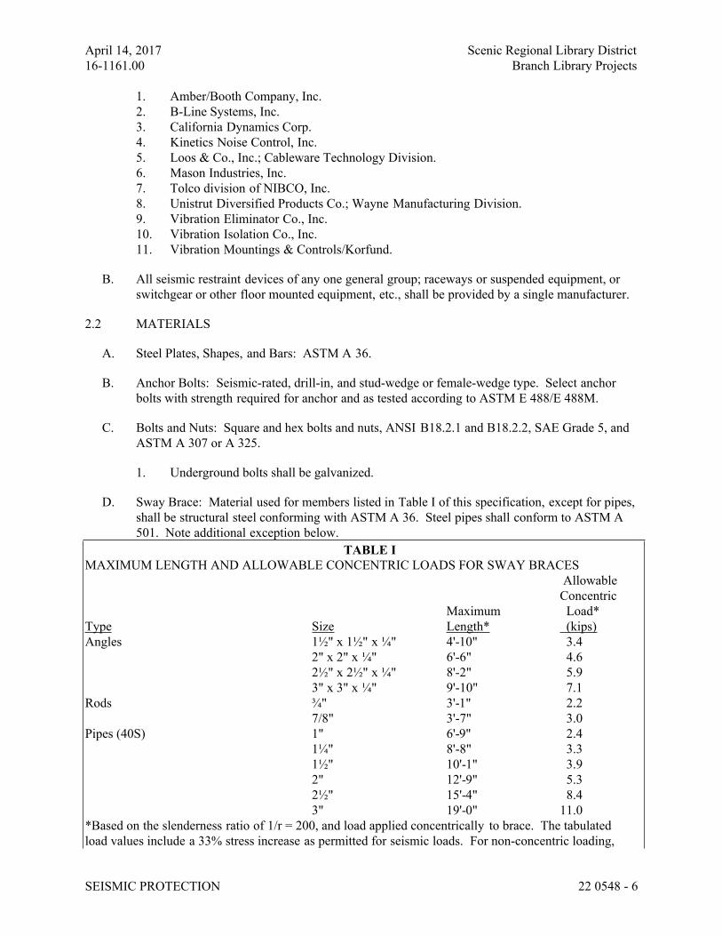
April 14, 2017 Scenic Regional Library District
16-1161.00 Branch Library Projects
SEISMIC PROTECTION 22 0548 - 6
1. Amber/Booth Company, Inc.
2. B-Line Systems, Inc.
3. California Dynamics Corp.
4. Kinetics Noise Control, Inc.
5. Loos & Co., Inc.; Cableware Technology Division.
6. Mason Industries, Inc.
7. Tolco division of NIBCO, Inc.
8. Unistrut Diversified Products Co.; Wayne Manufacturing Division.
9. Vibration Eliminator Co., Inc.
10. Vibration Isolation Co., Inc.
11. Vibration Mountings & Controls/Korfund.
B. All seismic restraint devices of any one general group; raceways or suspended equipment, or
switchgear or other floor mounted equipment, etc., shall be provided by a single manufacturer.
2.2 MATERIALS
A. Steel Plates, Shapes, and Bars: ASTM A 36.
B. Anchor Bolts: Seismic-rated, drill-in, and stud-wedge or female-wedge type. Select anchor
bolts with strength required for anchor and as tested according to ASTM E 488/E 488M.
C. Bolts and Nuts: Square and hex bolts and nuts, ANSI B18.2.1 and B18.2.2, SAE Grade 5, and
ASTM A 307 or A 325.
1. Underground bolts shall be galvanized.
D. Sway Brace: Material used for members listed in Table I of this specification, except for pipes,
shall be structural steel conforming with ASTM A 36. Steel pipes shall conform to ASTM A
501. Note additional exception below.
TABLE I
MAXIMUM LENGTH AND ALLOWABLE CONCENTRIC LOADS FOR SWAY BRACES
Allowable
Concentric
Maximum Load*
Type Size Length* (kips)
Angles 1½" x 1½" x ¼" 4'-10" 3.4
2" x 2" x ¼" 6'-6" 4.6
2½" x 2½" x ¼" 8'-2" 5.9
3" x 3" x ¼" 9'-10" 7.1
Rods ¾" 3'-1" 2.2
7/8" 3'-7" 3.0
Pipes (40S) 1" 6'-9" 2.4
1¼" 8'-8" 3.3
1½" 10'-1" 3.9
2" 12'-9" 5.3
2½" 15'-4" 8.4
3" 19'-0" 11.0
*Based on the slenderness ratio of 1/r = 200, and load applied concentrically to brace. The tabulated
load values include a 33% stress increase as permitted for seismic loads. For non-concentric loading,
April 14, 2017 Scenic Regional Library District
16-1161.00 Branch Library Projects
SEISMIC PROTECTION 22 0548 - 7
allowable brace load is to be determined per the AISC Specification for Structural Steel Buildings / ASD
1989.
1. Contractor’s Option: In lieu of utilizing angles, rods, bars or pipes as noted in Table I,
U-channel systems consisting of channels, fittings and accessories may be utilized. The
u-channel system shall be manufactured as a complete system by one supplier and listed
by the manufacturer for use in seismic restraint application. The system shall have the
approval of OSHPD. The equipment shall provide multi-directional bracing of plumbing
piping systems.
E. Restraining Cables: Galvanized steel aircraft cables with end connections made of steel
assemblies that swivel to final installation angle and utilize two clamping bolts for cable
engagement. Cables shall conform to Fed. Spec RR-W-410 as follows:
1. 5/32 inch diameter Type V, Class 1
2. 3/16 inch to 5/16 diameter Type V, Class 2
3. 1/4 inch to 5/8 diameter Type I, Class 2
F. Resilient Isolation Washers and Bushings: 1-piece, molded, bridge-bearing neoprene
complying with AASHTO M 251 and having a durometer of 50, plus or minus 5, with a flat
washer face.
G. Seismic Snubbers: Factory fabricated using welded structural-steel shapes and plates, anchor
bolts, and replaceable resilient isolation washers and bushings.
H. Flexible Couplings: Flexible couplings shall have same pressure ratings as adjoining pipe.
I. Cement Grout: Portland cement (ASTM C 150, Type I or Type III) and clean uniformly
graded, natural sand (ASTM C 404, Size No. 2). Mix ratio shall be 1.0 part cement to 3.0 parts
sand, by volume, with minimum amount of water required for placement and hydration.
J. Galvanizing Repair Paint: High-zinc-dust-content paint, with dry film containing not less than
94 percent zinc dust by weight.
PART 3 - EXECUTION
3.1 EXAMINATION
A. Examine areas and equipment to receive seismic-control devices for compliance with
requirements, installation tolerances, and other conditions affecting performance.
B. Examine roughing-in of reinforcement and cast-in-place anchors to verify actual locations
before installation.
C. Examine substrates and conditions under which seismic supports and restraints are to be
installed
D. Proceed with installation only after unsatisfactory conditions have been corrected.
3.2 SEISMIC PROTECTION, GENERAL
April 14, 2017 Scenic Regional Library District
16-1161.00 Branch Library Projects
SEISMIC PROTECTION 22 0548 - 8
A. Attachments and supports for plumbing systems and components shall be designed to resist the
seismic forces specified herein.
B. Plumbing systems and components shall be designed by their manufacturer to consider dynamic
effects of the equipment and its contents. Design, selection, and installation of seismic bracing
for plumbing systems and components shall account for interaction between equipment and
supporting structures, and the effect imposed by attached utility or service lines, and shall
ensure that impact between components is avoided during a seismic event.
C. Anchorage: Install seismic supports and restraints complete with necessary inserts, bolts, rods,
nuts, washers, and other accessories.
1. Friction resulting from gravity loads shall not be considered to provide resistance to
seismic loads.
2. All bolts, including fasteners and anchor bolts, used for attachment of anchors to
components and to structure shall be sized for the seismic forces described in Part I but
shall not be less than ½-inch diameter in any case.
3. Powder-driven fasteners and shot pins shall not be permitted in tension load applications.
4. Expansion anchors, other than undercut expansion anchors, shall not be permitted to
anchor non-vibration isolated equipment rated over 10 horsepower.
5. Anchorage Embedment Depth: Not less than eight times the anchorage diameter.
6. Anchorage Edge Distance: Place anchorage not less than ten times the anchorage
diameter from edge of concrete housekeeping pad.
D. Base-Mounted Equipment: Anchor equipment to concrete base according to supported
equipment manufacturer's written instructions for seismic forces at Project site.
1. Concrete equipment pads shall be anchored to the supporting structure as required to
resist the seismic loads specified herein. Anchorage shall adequately distribute loads to
the elements of the supporting structure; coordinate with building structural engineer if
required. Anchorage devices may consist of either cast-in-place or drilled-in and epoxy
grouted reinforcing steel dowels. Unless otherwise indicated, install dowel rods to
connect concrete base to concrete floor on 18-inch (450-mm) centers around the full
perimeter of the base.
2. All floor or pad mounted equipment shall be anchored with cast-in-place anchor bolts,
expansion bolts or epoxy bolts. For vibratory equipment, the nuts shall be secured
against loosening by either installing double nuts, tack welding single nut to bolt or
scoring bolt threads.
3. Install epoxy-coated anchor bolts for supported equipment that extend through concrete
base and anchor into structural concrete floor.
4. Place and secure anchorage devices. Use Setting Drawings, templates, diagrams,
instructions, and directions furnished with items to be embedded.
5. Install anchor bolts to elevations required for proper attachment to supported equipment.
6. Install anchor bolts according to anchor-bolt manufacturer's written instructions.
7. Cast-in-place concrete materials and placement requirements are specified in
Division 03.
E. Resilient Vibration Isolation Devices: Selection of anchor bolts for vibration isolation devices
and/or snubbers to equipment base and foundations shall follow the same procedure as for
base-mounted equipment in subsection above, except that the seismic force found in Part 1
April 14, 2017 Scenic Regional Library District
16-1161.00 Branch Library Projects
SEISMIC PROTECTION 22 0548 - 9
shall be doubled for the purpose of selecting isolation devices, anchorage, and snubbers.
1. Vibration Isolation Devices are suitable for seismic restraint provided the vertical and
horizontal seismic forces are within the limits designed into the device.
2. Resilient and Spring-Type Vibration Devices: Vibration isolation devices shall be
selected so that the maximum movement of equipment from the static deflection point
shall be 0.5 inches.
3. Multidirectional Seismic Snubbers: If vibration isolators are required then
multidirectional seismic snubbers employing elastomeric pads shall be installed on all
vibration isolated equipment. These snubbers shall provide 0.25-inches free vertical and
horizontal movement from the static deflection point. Locate snubbers as close as
possible to vibration isolators and bolt to equipment base and supporting structure.
Snubber medium shall consist of viscoelastic or other impact-limiting material arranged
around a flanged steel trunnion so both horizontal and vertical overturning forces are
resisted by the snubber medium.
4. Install resilient bolt isolation washers on equipment anchor bolts.
5. Do not short-circuit vibration isolation device with rigid connection directly to structure.
F. Equipment Sway Bracing: Required for all items supported from overhead structures. Braces
shall consist of angles, rods, bars, pipes, cables, or factory fabricated U-channel systems and
secured at both ends with not less than ½-inch bolts. Braces shall conform to Table 1, or as
recommended by U-channel systems fabricator. Bracing shall be provided in two planes of
directions, 90 degrees apart, for each item of equipment. Details of all equipment bracing shall
be submitted.
1. In lieu of bracing with vertical supports, these items may be supported with hangers
inclined at 45 degrees directed up and radially away from equipment and oriented
symmetrically in 90-degree intervals on the horizontal plane, bisecting the angles of each
corner of the equipment, provided that supporting members are properly sized to support
operating weight of equipment when hangers are inclined at a 45-degree angle.
3.3 PIPES
A. General: Select and install restraints for piping in complete and strict accordance with ANSI
Standard Seismic Restraint Manual; Guidelines for Mechanical Systems, as issued by the Sheet
Metal and Air Conditioning Contractors National Association, Inc., 1998; Chantilly, Virginia
including Addendum 1 published 2000; except where more stringent requirements are
described herein.
B. Transverse Sway Bracing: Transverse sway bracing shall be provided at each horizontal turn
of 45 degrees or more, at the end of each pipe run, and otherwise at regular intervals spaced no
further than required by the above Standard. Sway bracing shall be provided at closer intervals
if so recommended by U-channel manufacturer when using U-channel systems.
C. Longitudinal Sway Bracing: Longitudinal sway bracing shall be provided at regular intervals
spaced no further than required by the above Standard. Transverse bracing for one pipe section
may also act as longitudinal bracing for a pipe section connected perpendicular to it, if the
bracing is installed within 4 feet of the intersection, and if it is sized for the larger pipe. Sway
bracing shall be provided at closer intervals if so recommended by U-channel manufacturer
when using U-channel systems.
April 14, 2017 Scenic Regional Library District
16-1161.00 Branch Library Projects
SEISMIC PROTECTION 22 0548 - 10
D. Anchor Rods, Angles, and Bars: Anchor rods, angles, and bars shall be bolted to either pipe
clamps or pipe flanges at one end and cast-in-place concrete or masonry insert or clip angles
bolted to the steel structure on the other end. Rods shall be solid metal or pipe as required.
E. Restraining Cables: Install restraining cables slightly slack. Install cables so they do not bend
across sharp edges of adjacent equipment or building structure.
F. Hanger Rod Reinforcement: Install steel angles or channel, sized to prevent buckling, clamped
with ductile-iron clamps to hanger rods for trapeze and individual pipe and equipment hangers
where required. Do not weld angles to rods.
G. Clamps: Clamps on uninsulated pipes shall be applied directly to pipes. Insulated piping shall
have clamps applied over insulation vapor barrier with high-density inserts and metal
protection shields under each clamp. Vapor barrier shall not be punctured.
1. At trapeze anchor locations, shackle or clamp piping to trapeze.
H. Vertical Runs: Vertical runs of piping shall be braced at each floor and roof level. Provide
intermediate lateral braces at 13 foot maximum spacing where story height exceeds 13 feet.
I. Spreaders: Required between racked or adjacent piping runs to prevent contact during seismic
activity whenever pipe or insulated pipe surfaces are less than 4 inches (or four times the
maximum displacement due to seismic force) apart. Spreaders shall be applied at same interval
as sway braces. Spreaders shall be applied to surface of bare or insulated hot pipe, and over
insulation utilizing high-density inserts and pipe protection shields where vapor-barrier-type
insulation is employed.
J. Flexible Couplings or Joints: Flexible couplings and joints of the mechanical joint type may be
used for aboveground and underground piping. Flexible couplings or joints in building piping
shall be provided at bottom of all pipe risers larger than 3½ inches in diameter. Cast-iron waste
and vent piping need only comply with these provisions when caulked joints are used. Flexible
bell and spigot pipe joints using rubber gaskets or no-hub fittings may be used at each branch
adjacent to tees and elbows for underground waste piping inside of building to comply with
these requirements.
K. Mechanical couplings for steel or cast-iron pipe shall be of the sleeve type and shall provide a
tight flexible joint under all reasonable conditions, such as pipe movement caused by
expansion, contraction, slight settling or shifting of the ground, minor variations in trench
gradients, and traffic vibrations. Where permitted in other sections of these specifications,
joints utilizing split-half couplings with grooved or shouldered pipe ends may be used.
L. Sleeve-type couplings shall be used for joining plain-end pipe sections. The coupling shall
consist of one steel middle ring, two steel followers, two gaskets, and necessary steel bolts and
nuts to compress the gaskets. Underground bolts shall be galvanized.
M. Underground Piping: All underground piping shall have flexible couplings installed adjacent to
building. Additional flexible couplings shall be provided as follows:
1. On each side of the joints of demarcation between soils having widely differing degrees
of consolidation.
April 14, 2017 Scenic Regional Library District
16-1161.00 Branch Library Projects
SEISMIC PROTECTION 22 0548 - 11
2. At all points that can be considered to act as anchors.
3. On every branch of a tee and each side of an elbow.
N. Emergency Gas Supply Connections: Facilities which are to be connected to natural gas
distribution systems shall be provided with an aboveground locked, valved and capped
emergency gas supply connection. An automatic device to safely interrupt the flow of gas to
the building in case of an earthquake shall be provided as specified in Division 22 Section
“Facility Natural Gas Piping”. Provisions shall be made for attachment of a portable,
commercial-sized gas cylinder system to this connection. Connection shall be located within
12 inches of the exterior wall and clearly marked with an appropriate metal sign mounted on
wall above.
3.4 SEISMIC RELATIVE DISPLACEMENT
A. Do not attach seismic anchorage or bracing for any one component to two or more elements of
a structure subject to differential movement, such as a wall and a floor or two different floors.
Do not attach seismic anchorage or bracing for any one component to two or more separate
structures or structural systems.
B. Piping shall be designed to accommodate differential movement between components and
structures when attached to structures that could displace relative to each other and where the
components cross a seismic isolation interface. Examples include vertical pipe risers; or a pump
anchored to a floor and rigidly connected to piping anchored to the roof structure above.
1. Furnish and install sufficient flexible fittings to accommodate the relative displacement.
3.5 ADJUSTING
A. Support and Restraint Adjustment: Adjust supports and restraints to distribute loads equally on
attachments.
B. Adjust snubbers according to manufacturer’s written recommendations.
C. Adjust seismic restraints to permit free movement of equipment within normal mode of
operation.
D. Torque anchor bolts according to equipment manufacturer’s written recommendations to resist
seismic forces.
3.6 CLEANING
A. After completing equipment installation, inspect seismic-control devices. Remove paint
splatters and other spots, dirt, and debris.
B. Paint Touch-Up: Immediately after installation of equipment, devices and seismic protection
system; clean field welds, bolted connections, and abraded areas of shop paint. Apply paint to
exposed areas per requirements in Division 09 section “Painting”.
C. Galvanizing Touch-Up: Immediately after installation of equipment, devices and seismic
protection system; clean field welds, bolted connections, and abraded areas of galvanizing.
April 14, 2017 Scenic Regional Library District
16-1161.00 Branch Library Projects
SEISMIC PROTECTION 22 0548 - 12
Apply galvanizing repair paint to comply with ASTM A 780.
3.7 FIELD QUALITY CONTROL
A. Review: Engage an authorized representative of the seismic restraint vendor to perform the
following field quality control review:
1. Examine all plumbing systems and equipment to confirm all seismic-restraint systems
are installed properly and in compliance with these specifications and the submittals.
2. Examine all seismic restraints and seismic snubbers for minimum clearances.
3. Examine all cable bracing systems for proper installation, angle of slope, and tension or
slack.
B. Report: Submit a certification report of the authorized representative of the seismic restraint
vendor to verify the above review and to include the following:
1. Certify that all seismic-restraint systems are installed properly and in compliance with
these specifications and the submittals.
2. Identify those areas that require corrective measures or certify that no corrective
measures are necessary.
3. Any changes to the originally submitted seismic restraint designs, such as those due to
field coordination, shall be clearly defined and detailed in the report.
END OF SECTION 22 0548
April 14, 2017 Scenic Regional Library District
16-1161.00 Branch Library Projects
IDENTIFICATION FOR PLUMBING PIPING AND EQUIPMENT 22 0553 - 1
SECTION 22 0553 - IDENTIFICATION FOR PLUMBING PIPING AND EQUIPMENT
ALL LIBRARIES
PART 1 - GENERAL
1.1 RELATED DOCUMENTS
A. Drawings and general provisions of the Contract, including General and Supplementary
Conditions and Division 01 Specification Sections, apply to this Section.
1.2 SUMMARY
A. Section Includes:
1. Equipment labels.
2. Warning signs and labels.
3. Pipe labels.
4. Valve tags.
5. Warning tags.
1.3 SUBMITTALS
A. Product Data: For each type of product indicated.
B. Samples: For color, letter style, and graphic representation required for each identification
material and device.
C. Equipment Label Schedule: Include a listing of all equipment to be labeled.
D. Valve numbering scheme.
E. Valve Schedules: For each piping system to include in maintenance manuals.
1.4 COORDINATION
A. Coordinate installation of identifying devices with completion of covering and painting of
surfaces where devices are to be applied.
B. Coordinate installation of identifying devices with locations of access panels and doors.
C. Install identifying devices before installing acoustical ceilings and similar concealment.
PART 2 - PRODUCTS
2.1 EQUIPMENT LABELS
A. Metal Labels for Equipment:
1. Material and Thickness: Aluminum, 0.032-inch or anodized aluminum, 0.032-inch
minimum thickness, and having predrilled or stamped holes for attachment hardware.
April 14, 2017 Scenic Regional Library District
16-1161.00 Branch Library Projects
IDENTIFICATION FOR PLUMBING PIPING AND EQUIPMENT 22 0553 - 2
2. Minimum Label Size: Length and width vary for required label content, but not less than
2-1/2 by 3/4 inch.
3. Minimum Letter Size: 1/4 inch for name of units if viewing distance is less than 24
inches, 1/2 inch for viewing distances up to 72 inches, and proportionately larger lettering
for greater viewing distances. Include secondary lettering two-thirds to three-fourths the
size of principal lettering.
4. Fasteners: Stainless-steel rivets or self-tapping screws.
5. Adhesive: Contact-type permanent adhesive, compatible with label and with substrate.
B. Plastic Labels for Equipment:
1. Material and Thickness: Multilayer, multicolor, plastic labels for mechanical engraving,
1/16 inch thick, and having predrilled holes for attachment hardware.
2. Letter Color: Black.
3. Background Color: White.
4. Maximum Temperature: Able to withstand temperatures up to 160 deg F.
5. Minimum Label Size: Length and width vary for required label content, but not less than
2-1/2 by 3/4 inch.
6. Minimum Letter Size: 1/4 inch for name of units if viewing distance is less than 24
inches, 1/2 inch for viewing distances up to 72 inches, and proportionately larger lettering
for greater viewing distances. Include secondary lettering two-thirds to three-fourths the
size of principal lettering.
7. Fasteners: Stainless-steel rivets or self-tapping screws.
8. Adhesive: Contact-type permanent adhesive, compatible with label and with substrate.
C. Label Content: Include equipment's Drawing designation or unique equipment number,
Drawing numbers where equipment is indicated (plans, details, and schedules), plus the
Specification Section number and title where equipment is specified. Designations shall be in
both English and Spanish.
D. Equipment Label Schedule: For each item of equipment to be labeled, on 8-1/2-by-11-inch
(A4) bond paper. Tabulate equipment identification number and identify Drawing numbers
where equipment is indicated (plans, details, and schedules), plus the Specification Section
number and title where equipment is specified. Equipment schedule shall be included in
operation and maintenance data.
E. All labels and pipe markers located within plenum ceilings shall have a flame spread index of
not more than 25 and a smoke-developed index of not more than 50 complying with ASME E
84.
2.2 WARNING SIGNS AND LABELS
A. Material and Thickness: Multilayer, multicolor, plastic labels for mechanical engraving, 1/8
inch thick, and having predrilled holes for attachment hardware.
B. Letter Color: White.
C. Background Color: Red.
D. Maximum Temperature: Able to withstand temperatures up to 160 deg F.
April 14, 2017 Scenic Regional Library District
16-1161.00 Branch Library Projects
IDENTIFICATION FOR PLUMBING PIPING AND EQUIPMENT 22 0553 - 3
E. Minimum Label Size: Length and width vary for required label content, but not less than 2-1/2
by 3/4 inch.
F. Minimum Letter Size: 1/4 inch for name of units if viewing distance is less than 24 inches. 1/2
inch for viewing distances up to 72 inches, and proportionately larger lettering for greater
viewing distances. Include secondary lettering two-thirds to three-fourths the size of principal
lettering.
G. Fasteners: Stainless-steel rivets or self-tapping screws.
H. Adhesive: Contact-type permanent adhesive, compatible with label and with substrate.
I. Label Content: Include caution and warning information, plus emergency notification
instructions.
2.3 PIPE LABELS
A. General Requirements for Manufactured Pipe Labels: Preprinted, color-coded, with lettering
indicating service, and showing flow direction according to ASME A13.1.
B. Pretensioned Pipe Labels: Precoiled, semirigid plastic formed to cover full circumference of
pipe and to attach to pipe without fasteners or adhesive.
C. Self-Adhesive Pipe Labels: Printed plastic with contact-type, permanent-adhesive backing.
D. Pipe Label Contents: Include identification of piping service using same designations as used
on Drawings to include pipe size, and an arrow indicating flow direction.
1. Flow-Direction Arrows: Integral with piping system service lettering to accommodate
both directions or as separate unit on each pipe label to indicate flow direction.
2. Lettering Size: Minimum 1-1/2 -inches high.
E. Stencils will not be allowed.
2.4 VALVE TAGS
A. Valve Tags: Stamped or engraved with 1/4-inch letters for piping system abbreviation and 1/2-
inch numbers.
1. Tag Material: Brass, 0.032-inch minimum thickness, and having predrilled or stamped
holes for attachment hardware.
2. Fasteners: Brass beaded chain.
B. Valve Schedules: For each piping system, on 8-1/2-by-11-inch (A4) bond paper. Tabulate
valve number, piping system, system abbreviation (as shown on valve tag), location of valve
(room or space), normal-operating position (open, closed, or modulating), and variations for
identification. Mark valves for emergency shutoff and similar special uses.
1. Valve-tag schedule shall be included in operation and maintenance data.
April 14, 2017 Scenic Regional Library District
16-1161.00 Branch Library Projects
IDENTIFICATION FOR PLUMBING PIPING AND EQUIPMENT 22 0553 - 4
2.5 WARNING TAGS
A. Warning Tags: Preprinted or partially preprinted, accident-prevention tags, of plasticized card
stock with matte finish suitable for writing.
1. Size: 3 by 5-1/4 inches minimum.
2. Fasteners: Brass grommet and wire.
3. Nomenclature: Large-size primary caption such as "DANGER," "CAUTION," or
"DO NOT OPERATE".
4. Color: Yellow background with black lettering.
PART 3 - EXECUTION
3.1 PREPARATION
A. Clean piping and equipment surfaces of substances that could impair bond of identification
devices, including dirt, oil, grease, release agents, and incompatible primers, paints, and
encapsulants.
3.2 EQUIPMENT LABEL INSTALLATION
A. Install or permanently fasten labels on each major item of mechanical equipment.
B. Locate equipment labels where accessible and visible.
3.3 PIPE LABEL INSTALLATION
A. Piping Color-Coding: Where required painting of piping is specified in Division 09 Section
"Interior Painting."
B. Locate pipe labels where piping is exposed or above accessible ceilings in finished spaces;
machine rooms; accessible maintenance spaces such as shafts, tunnels, and plenums; and
exterior exposed locations as follows:
1. Near each valve and control device.
2. Near each branch connection, excluding short takeoffs for fixtures and terminal units.
Where flow pattern is not obvious, mark each pipe at branch.
3. Near penetrations through walls, floors, ceilings, and inaccessible enclosures.
4. At access doors, manholes, and similar access points that permit view of concealed
piping.
5. Near major equipment items and other points of origination and termination.
6. Spaced at maximum intervals of 25 feet along each run (horizontal and vertical). Reduce
intervals to 15 feet in areas of congested piping and equipment.
7. On piping above removable acoustical ceilings. Omit intermediately spaced labels.
C. Pipe Label Color Schedule:
1. Potable Domestic Water Piping:
a. Background Color: Green
b. Letter Color: White
April 14, 2017 Scenic Regional Library District
16-1161.00 Branch Library Projects
IDENTIFICATION FOR PLUMBING PIPING AND EQUIPMENT 22 0553 - 5
2. Sanitary Waste and Storm Drainage Piping:
a. Background Color: White.
b. Letter Color: Black.
3. Natural Gas Piping:
a. Background Color: Yellow
b. Letter Color: Black
3.4 VALVE-TAG INSTALLATION
A. Install tags on valves and control devices in piping systems, except check valves; valves within
factory-fabricated equipment units; shutoff valves; faucets; convenience and lawn-watering
hose connections; and similar roughing-in connections of end-use fixtures and units. List
tagged valves in a valve schedule. Submit valve schedule to Engineer and Owner’s
Representative at substantial completion.
B. Valve-Tag Application Schedule: Tag valves according to size, shape, and color scheme and
with captions similar to those indicated in the following subparagraphs:
1. Valve-Tag Size and Shape:
a. All Systems: 1-1/2 inches, round.
2. Valve-Tag Color:
a. Water: Green.
b. Air/Gas: Blue
c. Non Potable: Black
3. Incised Letter Color:
a. All Systems: White.
3.5 WARNING-TAG INSTALLATION
A. Write required message on, and attach warning tags to, equipment and other items where
required.
END OF SECTION 22 0553
March 17, 2017 Scenic Regional Library District
16-1161.00 Branch Library Projects
TESTING, ADJUSTING AND BALANCING 22 0593 - 1
SECTION 22 05 93 – TESTING, ADJUSTING AND BALANCING FOR PLUMBING
ALL LIBRARIES
PART 1 - GENERAL
1.1 WORK INCLUDES
A. Base Bid:
1. Plumbing Contractor Provide:
a. Balancing Piping System:
1) Domestic hot water and hot water return systems.
2) Pressure booster systems.
1.2 RELATED WORK
A. Specified elsewhere:
1. Refer to General Commissioning Requirements for additional project requirements. This
work shall be coordinated with the project Commissioning Authority.
1.3 DEFINITIONS
A. NEBB: National Environmental Balancing Bureau.
B. TAB: Testing, adjusting, and balancing.
C. TABB: Testing, Adjusting, and Balancing Bureau.
D. TAB Specialist: An entity engaged to perform TAB Work.
1.4 SUBMITTALS
A. Certified TAB reports.
B. Instrument calibration reports, to include the following:
1. Instrument type and make.
2. Serial number.
3. Application.
4. Dates of use.
5. Dates of calibration.
1.5 QUALITY ASSURANCE
A. TAB Contractor Qualifications: Engage a TAB entity certified.
1. TAB Field Supervisor: Employee of the TAB contractor and certified.
2. TAB Technician: Employee of the TAB contractor and who is certified by a TAB
technician.
B. Certify TAB field data reports and perform the following:
March 17, 2017 Scenic Regional Library District
16-1161.00 Branch Library Projects
TESTING, ADJUSTING AND BALANCING 22 0593 - 1
1. Review field data reports to validate accuracy of data and to prepare certified TAB
reports.
2. Certify that the TAB team complied with the procedures specified and referenced in this
Specification.
C. TAB Report Forms: Use standard TAB contractor's forms approved by Engineer and/or
Commissioning Authority.
1.6 COORDINATION
A. Notice: Provide seven days' advance written notice for each test. Include scheduled test dates
and times.
B. Perform TAB after leakage and pressure tests on water distribution systems have been
satisfactorily completed.
PART 2 - PRODUCTS (Not Applicable)
PART 3 - EXECUTION
3.1 EXAMINATION
A. Examine the Contract Documents to become familiar with Project requirements and to discover
conditions in systems' designs that may preclude proper TAB of systems and equipment.
B. Examine systems for installed balancing devices, such as test ports, gage cocks, thermometer
wells, flow-control devices, balancing valves and fittings. Verify that locations of these
balancing devices are accessible.
C. Examine the approved submittals for plumbing systems and equipment.
D. Examine design data including plumbing system descriptions, statements of design assumptions
for environmental conditions and systems' output, and statements of philosophies and
assumptions about plumbing system and equipment controls.
E. Examine equipment performance data including pump curves.
1. Relate performance data to Project conditions and requirements, including system effects
that can create undesired or unpredicted conditions that cause reduced capacities in all or
part of a system.
2. Calculate system-effect factors to reduce performance ratings of plumbing equipment
when installed under conditions different from the conditions used to rate equipment
performance.
F. Examine system and equipment installations and verify that field quality-control testing,
cleaning, and adjusting specified in individual Sections have been performed.
G. Examine test reports specified in individual system and equipment Sections.
H. Examine strainers. Verify that startup screens are replaced by permanent screens with indicated
perforations.
I. Examine thermostatic mixing valves for proper installation for their intended function of
diverting or mixing fluid flows.
March 17, 2017 Scenic Regional Library District
16-1161.00 Branch Library Projects
TESTING, ADJUSTING AND BALANCING 22 0593 - 1
J. Examine system pumps to ensure absence of entrained air in the suction piping.
K. Examine operating safety interlocks and controls on Plumbing equipment.
L. Report deficiencies discovered before and during performance of TAB procedures. Observe
and record system reactions to changes in conditions. Record default set points if different
from indicated values.
3.2 PREPARATION
A. Prepare a TAB plan that includes strategies and step-by-step procedures.
B. Complete system-readiness checks and prepare reports. Verify the following:
1. Permanent electrical-power wiring is complete.
2. Hydronic systems are filled, clean, and free of air.
3. Thermostatic mixing valves are operational and set to specified temperatures.
4. Isolating and balancing valves are open and control valves are operational.
5. Circulating pumps are operational.
6. Bleed air from system.
3.3 GENERAL PROCEDURES FOR TESTING AND BALANCING
A. Perform testing and balancing procedures on domestic hot water system in this section.
B. Cut insulation, pipes, and equipment cabinets for installation of test probes to the minimum
extent necessary for TAB procedures.
1. After testing and balancing, cap probe holes in pipes with same material and thickness.
2. Install and join new insulation that matches removed materials. Restore insulation,
coverings, vapor barrier, and finish according to Section 22 07 00 - Plumbing Insulation.
C. Mark equipment and balancing devices, including valve position indicators, and similar
controls and devices, with paint or other suitable, permanent identification material to show
final settings.
D. Take and report testing and balancing measurements in gpm flow rate.
3.4 GENERAL PROCEDURES FOR HYDRONIC SYSTEMS
A. Prepare test reports with pertinent design data, and number in sequence starting at pump to end
of system. Check the sum of branch-circuit flows against the approved pump flow rate.
Correct variations that exceed plus or minus 5 percent.
B. Prepare schematic diagrams of systems' "as-built" piping layouts.
C. Prepare hydronic systems for testing and balancing according to the following, in addition to
the general preparation procedures specified above:
1. Open all manual valves for maximum flow.
2. Check liquid level in expansion tank.
3. Check flow-control valves for specified sequence of operation, and set at indicated flow.
March 17, 2017 Scenic Regional Library District
16-1161.00 Branch Library Projects
TESTING, ADJUSTING AND BALANCING 22 0593 - 1
4. Check pump-motor load. If motor is overloaded, adjust VFD set points so motor
nameplate rating is not exceeded.
3.5 PROCEDURES FOR MOTORS
A. Motors, 1/2 HP and Larger: Test at final balanced conditions and record the following data:
1. Manufacturer's name, model number, and serial number.
2. Motor horsepower rating.
3. Motor rpm.
4. Efficiency rating.
5. Nameplate and measured voltage, each phase.
6. Nameplate and measured amperage, each phase.
7. Starter thermal-protection-element rating.
B. Motors Driven by Variable-Frequency Controllers: Test for proper operation at speeds varying
from minimum to maximum. Test the manual bypass of the controller to prove proper
operation. Record observations including name of controller manufacturer, model number,
serial number, and nameplate data.
3.6 FINAL REPORT
A. General: Prepare a certified written report; tabulate and divide the report into separate sections
for tested systems and balanced systems.
1. Include a certification sheet at the front of the report's binder, signed and sealed by the
certified testing and balancing engineer.
2. Include a list of instruments used for procedures, along with proof of calibration.
B. Final Report Contents: In addition to certified field-report data, include the following:
1. Pump curves.
2. Manufacturers' test data.
3. Field test reports prepared by system and equipment installers.
4. Other information relative to equipment performance; do not include Shop Drawings and
product data.
C. General Report Data: In addition to form titles and entries, include the following data:
1. Title page.
2. Name and address of the TAB contractor.
3. Project name.
4. Project location.
5. Engineer's name and address.
6. Contractor's name and address.
7. Report date.
8. Signature of TAB supervisor who certifies the report.
9. Table of Contents with the total number of pages defined for each section of the report.
Number each page in the report.
10. Summary of contents including the following:
March 17, 2017 Scenic Regional Library District
16-1161.00 Branch Library Projects
TESTING, ADJUSTING AND BALANCING 22 0593 - 1
a. Indicated versus final performance.
b. Notable characteristics of systems.
c. Description of system operation sequence if it varies from the Contract Documents.
11. Nomenclature sheets for each item of equipment.
12. Notes to explain why certain final data in the body of reports vary from indicated values.
13. Test conditions for pump performance forms including the following:
D. System Diagrams: Include schematic layouts of hydronic distribution system. Present each
system with single-line diagram and include the following:
1. Water flow rates in gpm.
2. Pipe and valve sizes and locations.
3. Balancing stations.
4. Position and gpm setting of balancing devices.
E. Pump Test Reports: Calculate impeller size by plotting the shutoff head on pump curves and
include the following:
1. Unit Data:
a. Unit identification.
b. Location.
c. Service.
d. Make and size.
e. Model number and serial number.
f. Water flow rate in gpm.
g. Water pressure differential in feet of head or psig.
h. Required net positive suction head in feet of head or psig.
i. Pump rpm.
j. Impeller diameter in inches.
k. Motor make and frame size.
l. Motor horsepower and rpm.
m. Voltage at each connection.
n. Amperage for each phase.
o. Full-load amperage and service factor.
p. Seal type.
2. Test Data (Indicated and Actual Values):
a. Static head in feet of head or psig.
b. Pump shutoff pressure in feet of head or psig.
c. Actual impeller size in inches.
d. Full-open flow rate in gpm.
e. Full-open pressure in feet of head or psig.
f. Final discharge pressure in feet of head or psig.
g. Final suction pressure in feet of head or psig.
h. Final total pressure in feet of head or psig.
i. Final water flow rate in gpm.
j. Voltage at each connection.
k. Amperage for each phase.
March 17, 2017 Scenic Regional Library District
16-1161.00 Branch Library Projects
TESTING, ADJUSTING AND BALANCING 22 0593 - 1
F. Instrument Calibration Reports:
1. Report Data:
a. Instrument type and make.
b. Serial number.
c. Application.
d. Dates of use.
e. Dates of calibration.
3.7 INSPECTIONS
A. Initial Inspection:
1. After testing and balancing are complete, operate each system and randomly check
measurements to verify that the system is operating according to the final test and balance
readings documented in the final report.
2. Check the following for each system:
a. Measure water flow of at least 10 percent of balancing valves.
b. Verify that balancing devices are marked with final balance position.
c. Note deviations from the Contract Documents in the final report.
B. Final Inspection:
1. After initial inspection is complete and documentation by random checks verifies that
testing and balancing are complete and accurately documented in the final report, request
that a final inspection be made by Engineer.
2. The TAB contractor's test and balance engineer shall conduct the inspection in the
presence of Engineer.
3. Engineer shall randomly select measurements, documented in the final report, to be
rechecked. Rechecking shall be limited to either 10 percent of the total measurements
recorded or the extent of measurements that can be accomplished in a normal 8-hour
business day.
4. If rechecks yield measurements that differ from the measurements documented in the
final report by more than the tolerances allowed, the measurements shall be noted as
"FAILED."
5. If the number of "FAILED" measurements is greater than 10 percent of the total
measurements checked during the final inspection, the testing and balancing shall be
considered incomplete and shall be rejected.
C. TAB Work will be considered defective if it does not pass final inspections. If TAB Work
fails, proceed as follows:
1. Recheck all measurements and make adjustments. Revise the final report and balancing
device settings to include all changes; resubmit the final report and request a second final
inspection.
2. If the second final inspection also fails, Owner may contract the services of another TAB
contractor to complete TAB Work according to the Contract Documents and deduct the
cost of the services from the original TAB contractor's final payment.
March 17, 2017 Scenic Regional Library District
16-1161.00 Branch Library Projects
TESTING, ADJUSTING AND BALANCING 22 0593 - 1
D. Prepare test and inspection reports.
END OF SECTION 22 05 93
April 14, 2017 Scenic Regional Library District
16-1161.00 Branch Library Projects
PLUMBING INSULATION 22 07 00 - 1
SECTION 22 07 00 - PLUMBING INSULATION
ALL LIBRARIES
PART 1 - GENERAL
1.1 RELATED DOCUMENTS
A. Drawings and general provisions of the Contract, including General and Supplementary
Conditions and Division 01 Specification Sections, apply to this Section.
B. Section 22 05 48 “Seismic Protection” and Section 22 01 00 “Common Work Results for
Plumbing” all apply to the work of this Section as if fully repeated herein.
C. Section 22 0400 “Plumbing Fixtures” apply to this section.
1.2 SUMMARY
A. Section includes insulating the following plumbing piping services:
1. Domestic cold-water piping.
2. Domestic hot-water and recirculating hot water piping.
3. Sanitary sewer.
4. Storm sewer and overflow sewer piping.
5. Roof and overflow drain bodies.
6. Supplies and drains for handicap-accessible lavatories and sinks.
7. Domestic chilled-water piping for drinking fountains.
B. This Section includes plumbing insulation for equipment, piping, and other installations,
including the following.
1. Insulation Materials:
a. Thermal and Vapor Double bubble foil Insulation.
b. Self-seal polyethylene/closed cell foam.
2. Insulating cements.
3. Adhesives.
4. Mastics.
5. Sealants.
6. Tapes.
7. Securements.
8. Corner angles.
1.3 DEFINITIONS
A. ASJ: All-service jacket.
April 14, 2017 Scenic Regional Library District
16-1161.00 Branch Library Projects
PLUMBING INSULATION 22 07 00 - 2
B. FSK: Foil, scrim, kraft paper.
C. SSL: Self-sealing lap.
D. PVDC: Polyvinylidene chloride.
E. Thermal Resistivity: “R-values” represent the reciprocal of thermal conductivity (k-value).
Thermal conductivity is the rate of heat flow through a homogenous material exactly 1 inch
thick. Thermal resistivities are expressed by the temperature difference in degrees F between
two exposed faces required to cause one BTU to flow through one square foot of material, in
one hour, at a given mean temperature.
F. Refer to Section 22 0100 for definitions of finished, interior, exterior, exposed, and concealed
locations.
1.4 SUBMITTALS
A. Product Data: For each type of product indicated, identify thermal conductivity, thickness, and
jackets (both factory and field applied, if any). Denote material thickness and usage.
B. Shop Drawings: Show details for the following:
1. Application of protective shields, saddles, and inserts at hangers for each type of
insulation and hanger.
2. Insulation application at pipe expansion joints for each type of insulation.
3. Insulation application at elbows, fittings, flanges, valves, and specialties for each type of
insulation.
4. Removable insulation at piping specialties, equipment connections, and access panels.
5. Application of field-applied jackets.
6. Application at linkages of control devices.
7. Field application for each pipe and equipment type.
C. Installer Certificates: Signed by Contractor certifying that installers comply with requirements.
D. Material Test Reports: From a qualified testing agency acceptable to authorities having
jurisdiction indicating, interpreting, and certifying test results for compliance of insulation
materials, sealers, attachments, cements, and jackets, with requirements indicated. Include
dates of tests and test methods employed.
E. Field quality-control inspection reports.
1.5 QUALITY ASSURANCE
A. Installer Qualifications: Skilled mechanics who have successfully completed an apprenticeship
program or another craft training program certified by the Department of Labor, Bureau of
Apprenticeship and Training.
B. Fire-Test-Response Characteristics: Insulation and related materials shall have fire-test-
response characteristics indicated, as determined by testing identical products per ASTM E 84,
April 14, 2017 Scenic Regional Library District
16-1161.00 Branch Library Projects
PLUMBING INSULATION 22 07 00 - 3
by a testing and inspecting agency acceptable to authorities having jurisdiction. Factory label
insulation and jacket materials and adhesive, mastic, and cement material containers, with
appropriate markings of applicable testing and inspecting agency.
1. Insulation Installed Indoors: Flame-spread index of 25 or less, and smoke-developed
index of 50 or less.
2. Insulation Installed Outdoors: Flame-spread index of 75 or less, and smoke-developed
index of 150 or less.
1.6 DELIVERY, STORAGE, AND HANDLING
A. Packaging: Insulation material containers shall be marked by manufacturer with appropriate
ASTM standard designation, type and grade, and maximum use temperature.
1.7 COORDINATION
A. Coordinate size and location of supports, hangers, and insulation shields specified in
Division 22 Section “Hangers and Supports.”
B. Coordinate clearance requirements with piping Installer for piping insulation application and
equipment Installer for equipment insulation application. Before preparing piping Shop
Drawings establish and maintain clearance requirements for installation of insulation and field-
applied jackets and finishes and for space required for maintenance.
C. Coordinate installation and testing of heat tracing.
1.8 SCHEDULING
A. Schedule insulation application after pressure testing systems and, where required, after
installing and testing heat tracing. Insulation application may begin on segments that have
satisfactory test results.
B. Complete installation and concealment of plastic materials as rapidly as possible in each area of
construction.
PART 2 - PRODUCTS
2.1 MANUFACTURERS
A. Manufacturers: Subject to compliance with requirements, provide products by one of the
following manufacturers:
1. Insulating Cements: Same as insulation manufacturer, or
a. Insulco, Division of MFS, Inc.
b. P. K. Insulation Mfg. Co., Inc.
c. Rock Wool Manufacturing Company.
April 14, 2017 Scenic Regional Library District
16-1161.00 Branch Library Projects
PLUMBING INSULATION 22 07 00 - 4
2. Sealants, Adhesives and Mastics: Same as insulation manufacturer, or
a. Childers Products, Division of ITW.
b. Foster Products Corporation, H. B. Fuller Company.
c. Marathon Industries, Inc.
3. Field-Applied Jackets: Same as insulation manufacturer, or
a. Childers Products, Division of ITW.
b. P.I.C. Plastics, Inc.
c. Pittsburgh Corning Corporation.
4. Tapes: Same as insulation manufacturer, or
a. Avery Dennison Corporation, Specialty Tapes Division.
b. Compac Corp.
c. Ideal Tape Co., Inc., an American Biltrite Company.
5. Bands and Wire: Same as insulation manufacturer, or
a. ACS Industries, Inc.
b. C & F Wire.
c. Childers Products.
6. Insulation Pins and Hangers: Same as insulation manufacturer, or
a. AGM Industries, Inc.
b. GEMCO.
c. Midwest Fasteners, Inc.
2.2 INSULATION MATERIALS
A. Refer to Schedule in Part 3 for requirements about where insulating materials shall be applied.
B. Products shall not contain asbestos, lead, mercury, or mercury compounds.
C. Products that come in contact with stainless steel shall have a leachable chloride content of less
than 50 ppm when tested according to ASTM C 871.
D. Insulation materials for use on austenitic stainless steel shall be qualified as acceptable
according to ASTM C 795.
E. Foam insulation materials shall not use CFC or HCFC blowing agents in the manufacturing
process.
F. Adhesives shall be compatible with insulation materials, jackets, and substrates and for bonding
insulation to itself and to surfaces to be insulated, unless otherwise indicated.
G. Flexible Elastomeric: Closed-cell, sponge- or expanded-rubber materials. Comply with
April 14, 2017 Scenic Regional Library District
16-1161.00 Branch Library Projects
PLUMBING INSULATION 22 07 00 - 5
ASTM C 534, Type I for tubular materials and Type II for sheet materials.
1. Thermal Conductivity: 0.28 average maximum at 75ºF mean temperature.
2. Adhesive: Comply with MIL-A-24179A, Type II, Class I.
H. Polyolefin: Unicellular, polyethylene thermal plastic insulation. Comply with ASTM C 534 or
ASTM C 1427, Type I, Grade 1 for tubular materials and Type II, Grade 1 for sheet materials.
1. Thermal Conductivity: 0.28 average maximum at 75ºF mean temperature.
2. Adhesive: Comply with MIL-A-24179A, Type II, Class I.
2.3 INSULATING CEMENTS
A. Mineral-Fiber Insulating Cement: Comply with ASTM C 195.
B. Expanded or Exfoliated Vermiculite Insulating Cement: Comply with ASTM C 196.
C. Mineral-Fiber, Hydraulic-Setting Insulating and Finishing Cement: Comply with
ASTM C 449/C 449M.
2.4 MASTICS
A. Materials shall be compatible with insulation materials, jackets, and substrates; comply with
MIL-C-19565C, Type II.
B. Vapor-Barrier Mastic: Water based; suitable for indoor and outdoor use on below-ambient
services.
1. Water-Vapor Permeance: ASTM E 96, Procedure B, 0.013 perm at 43-mil dry film
thickness.
2. Service Temperature Range: Minus 20 to plus 180ºF.
3. Solids Content: ASTM D 1644, 59 percent by volume and 71 percent by weight.
4. Color: White.
C. Breather Mastic: Water based; suitable for indoor and outdoor use on above-ambient services.
1. Water-Vapor Permeance: ASTM F 1249, 3 perms at 0.0625-inch dry film thickness.
2. Service Temperature Range: Minus 20 to plus 200ºF.
3. Solids Content: 63 percent by volume and 73 percent by weight.
4. Color: White.
2.5 SEALANTS
A. Joint Sealants:
1. Materials shall be compatible with insulation materials, jackets, and substrates.
2. Permanently flexible, elastomeric sealant.
3. Service Temperature Range: Minus 100 to plus 300ºF.
4. Color: White or gray.
April 14, 2017 Scenic Regional Library District
16-1161.00 Branch Library Projects
PLUMBING INSULATION 22 07 00 - 6
B. ASJ Flashing Sealants, and Vinyl and PVC Jacket Flashing Sealants:
1. Materials shall be compatible with insulation materials, jackets, and substrates.
2. Fire- and water-resistant, flexible, elastomeric sealant.
3. Service Temperature Range: Minus 40 to plus 250ºF.
4. Color: White.
2.6 TAPES
A. ASJ Tape: White vapor-retarder tape matching factory-applied jacket with acrylic adhesive,
complying with ASTM C 1136 and UL listed.
1. Width: 3 inches.
2. Thickness: 11.5 mils.
3. Adhesion: 90 ounces force/inch in width.
4. Elongation: 2 percent.
5. Tensile Strength: 40 lbf/inch in width.
6. ASJ Tape Disks and Squares: Precut disks or squares of ASJ tape.
B. FSK Tape: Foil-face, vapor-retarder tape matching factory-applied jacket with acrylic adhesive;
complying with ASTM C 1136 and UL listed.
1. Width: 3 inches.
2. Thickness: 6.5 mils.
3. Adhesion: 90 ounces force/inch in width.
4. Elongation: 2 percent.
5. Tensile Strength: 40 lbf/inch in width.
6. FSK Tape Disks and Squares: Precut disks or squares of FSK tape.
C. PVC Tape: White vapor-retarder tape matching field-applied PVC jacket with acrylic adhesive.
Suitable for indoor and outdoor applications.
1. Width: 2 inches.
2. Thickness: 6 mils.
3. Adhesion: 64 ounces force/inch in width.
4. Elongation: 500 percent.
5. Tensile Strength: 18 lbf/inch in width.
D. Aluminum-Foil Tape: Vapor-retarder tape with acrylic adhesive and UL listed.
1. Width: 2 inches.
2. Thickness: 3.7 mils.
3. Adhesion: 100 ounces force/inch in width.
4. Elongation: 5 percent.
5. Tensile Strength: 34 lbf/inch in width.
E. PVDC Tape for Indoor Applications: White vapor-retarder PVDC tape with acrylic adhesive.
April 14, 2017 Scenic Regional Library District
16-1161.00 Branch Library Projects
PLUMBING INSULATION 22 07 00 - 7
1. Width: 3 inches.
2. Film Thickness: 6 mils; except 4 mils where used indoors.
3. Adhesive Thickness: 1.5 mils.
4. Elongation at Break: 145 percent.
5. Tensile Strength: 55 lbf/inch in width.
2.7 SECUREMENTS
A. Bands:
1. Stainless Steel: ASTM A 167 or ASTM A 240/A 240M, Type 304; 0.015 inch thick, ½
inch wide with wing or closed seal.
2. Aluminum: ASTM B 209 (ASTM B 209M), Alloy 3003, 3005, 3105, or 5005;
Temper H-14, 0.020 inch thick, ½ inch wide with wing or closed seal.
3. Springs: Twin spring set constructed of stainless steel with ends flat and slotted to accept
metal bands. Spring size determined by manufacturer for application.
B. Insulation Pins and Hangers:
1. Capacitor-Discharge-Weld Pins: Copper- or zinc-coated steel pin, fully annealed for
capacitor-discharge welding, 0.106-inch- diameter shank, length to suit depth of
insulation indicated.
2. Cupped-Head, Capacitor-Discharge-Weld Pins: Copper- or zinc-coated steel pin, fully
annealed for capacitor-discharge welding, 0.106-inch- diameter shank, length to suit
depth of insulation indicated with integral 1½-inch galvanized carbon-steel washer.
3. Metal, Adhesively Attached, Perforated-Base Insulation Hangers: Baseplate welded to
projecting spindle that is capable of holding insulation, of thickness indicated, securely in
position indicated when self-locking washer is in place. Comply with the following
requirements:
a. Baseplate: Perforated, galvanized carbon-steel sheet, 0.030 inch
b. Adhesive: Recommended by hanger manufacturer. Product with demonstrated
capability to bond insulation hanger securely to substrates indicated without
damaging insulation, hangers, and substrates.
4. Nonmetal, Adhesively Attached, Perforated-Base Insulation Hangers: Baseplate fastened
to projecting spindle that is capable of holding insulation, of thickness indicated, securely
in position indicated when self-locking washer is in place. Comply with the following
requirements:
a. Baseplate: Perforated, nylon sheet, 0.030 inch thick by 1½ inches in diameter.
b. Spindle: Nylon, 0.106-inch- diameter shank, length to suit depth of insulation
indicated, up to 2½ inches.
c. Adhesive: Recommended by hanger manufacturer. Product with demonstrated
capability to bond insulation hanger securely to substrates indicated without
damaging insulation, hangers, and substrates.
5. Self-Sticking-Base Insulation Hangers: Baseplate welded to projecting spindle that is
capable of holding insulation, of thickness indicated, securely in position indicated when
self-locking washer is in place. Comply with the following requirements:
April 14, 2017 Scenic Regional Library District
16-1161.00 Branch Library Projects
PLUMBING INSULATION 22 07 00 - 8
a. Baseplate: Galvanized carbon-steel sheet, 0.030 inch thick by 2 inches square.
b. Spindle: Copper, aluminum, or stainless steel, fully annealed, 0.106-inch-
diameter shank, length to suit depth of insulation indicated.
c. Adhesive-backed base with a peel-off protective cover.
6. Insulation-Retaining Washers: Self-locking washers formed from 0.016-inch thick,
aluminum or stainless-steel sheet, with beveled edge sized as required to hold insulation
securely in place but not less than 1½ inches in diameter.
a. Protect ends with capped self-locking washers incorporating a spring steel insert to
ensure permanent retention of cap in exposed locations.
7. Nonmetal Insulation-Retaining Washers: Self-locking washers formed from 0.016-inch-
thick nylon sheet, with beveled edge sized as required to hold insulation securely in place
but not less than 1½ inches in diameter.
C. Staples: Outward-clinching insulation staples, nominal ¾-inch- wide, stainless steel or Monel.
D. Wire: 0.062-inch soft-annealed, stainless steel.
2.8 CORNER ANGLES
A. PVC Corner Angles: 30 mils thick, minimum 1 by 1 inch, PVC according to ASTM D 1784,
Class 16354-C. White or color-coded to match adjacent surface.
PART 3 - EXECUTION
3.1 EXAMINATION
A. Examine substrates and conditions for compliance with requirements for installation and other
conditions affecting performance of insulation application.
1. Verify that systems and equipment to be insulated have been tested and are free of
defects.
2. Verify that surfaces to be insulated are clean and dry.
3. Proceed with installation only after unsatisfactory conditions have been corrected.
3.2 PREPARATION
A. Surface Preparation: Clean and dry surfaces to receive insulation. Remove materials that will
adversely affect insulation application.
3.3 COMMON INSTALLATION REQUIREMENTS
A. Install insulation materials, accessories, and finishes with smooth, straight, and even surfaces;
free of voids throughout the length of equipment, and fittings, and piping including fittings,
valves, and specialties.
April 14, 2017 Scenic Regional Library District
16-1161.00 Branch Library Projects
PLUMBING INSULATION 22 07 00 - 9
B. Install insulation materials, forms, vapor barriers or retarders, jackets, and thicknesses required
for each item of equipment, and pipe system as specified in insulation system schedules.
C. Install accessories compatible with insulation materials and suitable for the service. Install
accessories that do not corrode, soften, or otherwise attack insulation or jacket in either wet or
dry state.
D. Install insulation with longitudinal seams at top and bottom of horizontal runs.
E. Install multiple layers of insulation with longitudinal and end seams staggered.
F. Do not weld brackets, clips, or other attachment devices to piping, fittings, and specialties.
G. Keep insulation materials dry during application and finishing.
H. Install insulation with tight longitudinal seams and end joints. Bond seams and joints with
adhesive recommended by insulation material manufacturer.
I. Install insulation with least number of joints practical.
J. Apply adhesives, mastics, and sealants at manufacturer's recommended coverage rate and wet
and dry film thicknesses.
K. Cut insulation in a manner to avoid compressing insulation more than 75 percent of its nominal
thickness.
L. Finish installation with systems at operating conditions. Repair joint separations and cracking
due to thermal movement.
M. Repair damaged insulation facings by applying same facing material over damaged areas.
Extend patches at least 4 inches beyond damaged areas. Adhere, staple, and seal patches similar
to butt joints.
3.4 PENETRATIONS
A. Insulation Installation at Roof Penetrations: Install insulation continuously through roof
penetrations.
1. Seal penetrations with flashing sealant.
2. For applications requiring only indoor insulation, terminate insulation above roof surface
and seal with joint sealant. For applications requiring indoor and outdoor insulation,
install insulation for outdoor applications tightly joined to indoor insulation ends. Seal
joint with joint sealant.
3. Extend jacket of outdoor insulation outside roof flashing at least 2 inches below top of
roof flashing.
4. Seal jacket to roof flashing with flashing sealant.
B. Insulation Installation at Aboveground Exterior Wall Penetrations: Install insulation
continuously through wall penetrations.
April 14, 2017 Scenic Regional Library District
16-1161.00 Branch Library Projects
PLUMBING INSULATION 22 07 00 - 10
1. Seal penetrations with flashing sealant.
2. For applications requiring only indoor insulation, terminate insulation inside wall surface
and seal with joint sealant. For applications requiring indoor and outdoor insulation,
install insulation for outdoor applications tightly joined to indoor insulation ends. Seal
joint with joint sealant.
3. Extend jacket of outdoor insulation outside wall flashing and overlap wall flashing at
least 2 inches.
4. Seal jacket to wall flashing with flashing sealant.
C. Insulation Installation at Interior Wall and Partition Penetrations (That Are Not Fire Rated):
Install insulation continuously through walls and partitions.
D. Insulation Installation at Fire-Rated Wall and Partition Penetrations: Install insulation
continuously through penetrations of fire-rated walls and partitions. Terminate insulation at fire
damper sleeves for fire-rated wall and partition penetrations. Externally insulate damper
sleeves to match adjacent insulation and overlap duct insulation at least 2 inches.
1. Firestopping and fire-resistive joint sealers are specified in Division 07 Section
“Through-Penetration Firestop Systems.”
3.5 PIPE INSULATION INSTALLATION
A. Requirements in this Article generally apply to all insulation materials except where more
specific requirements are specified in various pipe insulation material installation articles.
B. Insulation Installation on Straight Pipes and Tubes:
1. Secure each layer of insulation to pipe with tape or bands and tighten without deforming
insulation materials. If furnished in half sections, orient longitudinal joints at 3 and 9
o'clock positions on the pipe.
2. All insulation shall be tightly butted and free of voids and gaps at all joints.
3. Where vapor barriers are indicated, seal longitudinal seams, end joints, and protrusions
with vapor-barrier mastic and joint sealant.
4. For insulation with factory-applied jackets on above ambient services, secure laps with
outward clinched staples at 6 inches o.c.
C. Insulation Installation on Pipe Flanges:
1. Install preformed pipe insulation to outer diameter of pipe flange.
2. Make width of insulation section same as overall width of flange and bolts, plus twice the
thickness of pipe insulation, not to exceed 1½-inch thickness.
3. Fill voids between inner circumference of flange insulation and outer circumference of
adjacent straight pipe segments with cut sections of block insulation of same thickness as
pipe insulation.
4. Install jacket material with manufacturer's recommended adhesive, overlap seams at least
1 inch and seal joints with flashing sealant.
D. Insulation Installation on Pipe Fittings and Elbows:
1. Install preformed sections of same material as straight segments of pipe insulation when
April 14, 2017 Scenic Regional Library District
16-1161.00 Branch Library Projects
PLUMBING INSULATION 22 07 00 - 11
available. Secure according to manufacturer's written instructions.
2. When preformed insulation elbows and fittings are not available, install mitered sections
of pipe insulation, to a thickness equal to adjoining pipe insulation. Secure insulation
materials with wire or bands.
3. Cut sectional pipe insulation to fit. Each piece shall be butted tightly against adjoining
piece and bonded with adhesive. Fill joints, seams, voids, and irregular surfaces with
insulating cement finished to a smooth, hard, and uniform contour that is uniform with
adjoining pipe insulation.
E. Insulation Installation on Valves, Strainers, Unions, and Specials:
1. Insulate valves using preformed fitting insulation or sectional pipe insulation of same
material, density, and thickness as used for adjacent pipe. Overlap adjoining pipe
insulation by not less than two times the thickness of pipe insulation, or one pipe
diameter, whichever is thicker. For valves, insulate up to and including the bonnets,
valve stuffing-box studs, bolts, and nuts. Fill joints, seams, and irregular surfaces with
insulating cement.
2. Arrange insulation to permit access to packing and to allow valve operation without
disturbing insulation.
3. Install insulation over valves, strainers, flanges, unions, and other specialties with
continuous thermal and vapor-retarder integrity, unless otherwise indicated.
4. Insulate strainers using preformed fitting insulation or sectional pipe insulation of same
material, density, and thickness as used for adjacent pipe. Overlap adjoining pipe
insulation by not less than two times the thickness of pipe insulation, or one pipe
diameter, whichever is thicker. Fill joints, seams, and irregular surfaces with insulating
cement. Insulate strainers so strainer basket flange or plug can be easily removed and
replaced without damaging the insulation and jacket. Provide a removable reusable
insulation cover. For below-ambient services, provide a design that maintains vapor
barrier.
5. Insulate unions using a section of oversized preformed pipe insulation. Overlap
adjoining pipe insulation by not less than two times the thickness of pipe insulation, or
one pipe diameter, whichever is thicker.
6. Cover segmented insulated surfaces with a layer of finishing cement and coat with a
mastic. Install vapor-barrier mastic for below ambient services and a breather mastic for
above ambient services. Reinforce the mastic with fabric-reinforcing mesh. Trowel the
mastic to a smooth and well-shaped contour.
7. Stencil or label the outside insulation jacket of each union with the word “UNION.”
Match size and color of pipe labels.
F. Insulate instrument connections for thermometers, pressure gages, pressure temperature taps,
test connections, flow meters, sensors, switches, and transmitters on insulated pipes, vessels,
and equipment. Shape insulation at these connections by tapering it to and around the
connection with insulating cement and finish with finishing cement, mastic, and flashing
sealant.
G. Install removable insulation covers at locations indicated. Installation shall conform to the
following:
1. Make removable flange and union insulation from sectional pipe insulation of same
thickness as that on adjoining pipe. Install same insulation jacket as adjoining pipe
insulation.
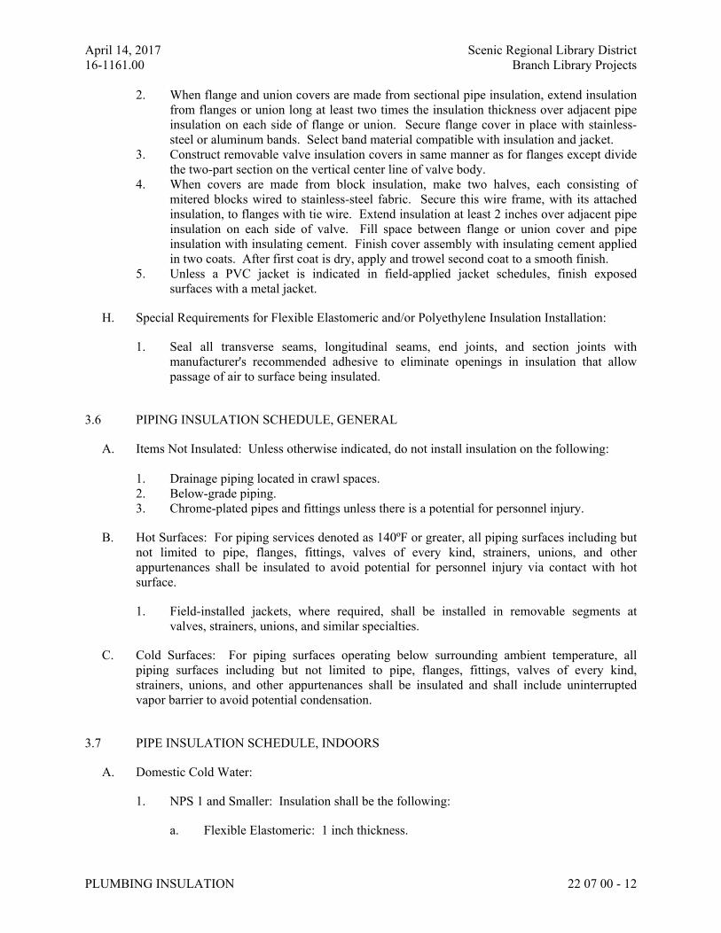
April 14, 2017 Scenic Regional Library District
16-1161.00 Branch Library Projects
PLUMBING INSULATION 22 07 00 - 12
2. When flange and union covers are made from sectional pipe insulation, extend insulation
from flanges or union long at least two times the insulation thickness over adjacent pipe
insulation on each side of flange or union. Secure flange cover in place with stainless-
steel or aluminum bands. Select band material compatible with insulation and jacket.
3. Construct removable valve insulation covers in same manner as for flanges except divide
the two-part section on the vertical center line of valve body.
4. When covers are made from block insulation, make two halves, each consisting of
mitered blocks wired to stainless-steel fabric. Secure this wire frame, with its attached
insulation, to flanges with tie wire. Extend insulation at least 2 inches over adjacent pipe
insulation on each side of valve. Fill space between flange or union cover and pipe
insulation with insulating cement. Finish cover assembly with insulating cement applied
in two coats. After first coat is dry, apply and trowel second coat to a smooth finish.
5. Unless a PVC jacket is indicated in field-applied jacket schedules, finish exposed
surfaces with a metal jacket.
H. Special Requirements for Flexible Elastomeric and/or Polyethylene Insulation Installation:
1. Seal all transverse seams, longitudinal seams, end joints, and section joints with
manufacturer's recommended adhesive to eliminate openings in insulation that allow
passage of air to surface being insulated.
3.6 PIPING INSULATION SCHEDULE, GENERAL
A. Items Not Insulated: Unless otherwise indicated, do not install insulation on the following:
1. Drainage piping located in crawl spaces.
2. Below-grade piping.
3. Chrome-plated pipes and fittings unless there is a potential for personnel injury.
B. Hot Surfaces: For piping services denoted as 140ºF or greater, all piping surfaces including but
not limited to pipe, flanges, fittings, valves of every kind, strainers, unions, and other
appurtenances shall be insulated to avoid potential for personnel injury via contact with hot
surface.
1. Field-installed jackets, where required, shall be installed in removable segments at
valves, strainers, unions, and similar specialties.
C. Cold Surfaces: For piping surfaces operating below surrounding ambient temperature, all
piping surfaces including but not limited to pipe, flanges, fittings, valves of every kind,
strainers, unions, and other appurtenances shall be insulated and shall include uninterrupted
vapor barrier to avoid potential condensation.
3.7 PIPE INSULATION SCHEDULE, INDOORS
A. Domestic Cold Water:
1. NPS 1 and Smaller: Insulation shall be the following:
a. Flexible Elastomeric: 1 inch thickness.
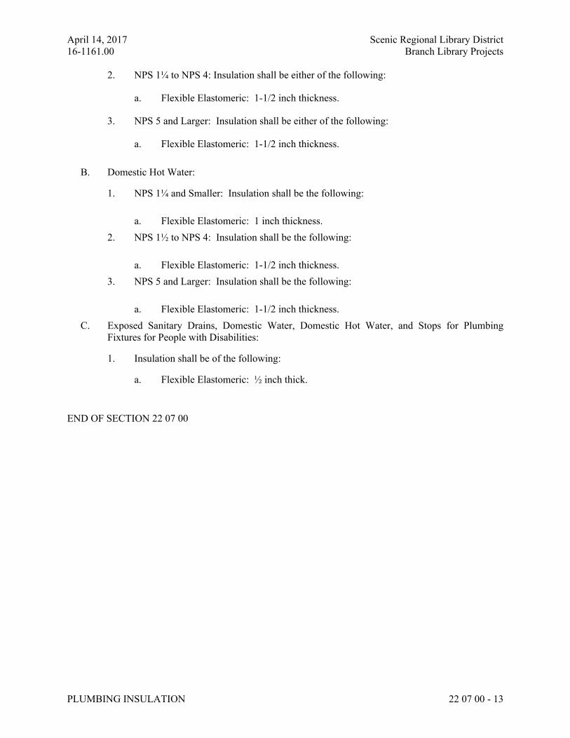
April 14, 2017 Scenic Regional Library District
16-1161.00 Branch Library Projects
PLUMBING INSULATION 22 07 00 - 13
2. NPS 1¼ to NPS 4: Insulation shall be either of the following:
a. Flexible Elastomeric: 1-1/2 inch thickness.
3. NPS 5 and Larger: Insulation shall be either of the following:
a. Flexible Elastomeric: 1-1/2 inch thickness.
B. Domestic Hot Water:
1. NPS 1¼ and Smaller: Insulation shall be the following:
a. Flexible Elastomeric: 1 inch thickness.
2. NPS 1½ to NPS 4: Insulation shall be the following:
a. Flexible Elastomeric: 1-1/2 inch thickness.
3. NPS 5 and Larger: Insulation shall be the following:
a. Flexible Elastomeric: 1-1/2 inch thickness.
C. Exposed Sanitary Drains, Domestic Water, Domestic Hot Water, and Stops for Plumbing
Fixtures for People with Disabilities:
1. Insulation shall be of the following:
a. Flexible Elastomeric: ½ inch thick.
END OF SECTION 22 07 00
April 14, 2017 Scenic Regional Library District
16-1161.00 Branch Library Projects
DOMESTIC WATER PIPING 22 1116 - 1
SECTION 22 1116 - DOMESTIC WATER PIPING
ALL LIBRARIES
PART 1 - GENERAL
1.1 RELATED DOCUMENTS
A. Drawings and general provisions of the Contract, including General and Supplementary
Conditions and Division 01 Specification Sections, apply to this Section.
1.2 SUMMARY
A. Section Includes:
1. Under-building slab and aboveground domestic potable and non-potable water pipes,
tubes, fittings, and specialties inside the building.
2. Encasement for piping.
3. Specialty valves.
4. Flexible connectors.
5. Water meters furnished by utility company for installation by Contractor.
6. Water meters.
1.3 PERFORMANCE REQUIREMENTS
A. Seismic Performance: Domestic water piping and support and installation shall withstand
effects of earthquake motions determined according to 22 0548 "Seismic Protection."
1.4 SUBMITTALS
A. Product Data: For the following products:
1. Specialty valves.
2. Flexible connectors.
3. Water meters.
B. Water Samples: Specified in "Cleaning" Article.
C. Coordination Drawings: For piping in equipment rooms and other congested areas, drawn to
scale, on which the following items are shown and coordinated with each other, using input
from Installers of the items involved:
1. Domestic water piping.
2. HVAC ductwork.
3. Natural gas.
4. Soil, waste and vent piping.
5. Storm water piping.
D. Field quality-control reports.
April 14, 2017 Scenic Regional Library District
16-1161.00 Branch Library Projects
DOMESTIC WATER PIPING 22 1116 - 2
1.5 QUALITY ASSURANCE
A. Piping materials shall bear label, stamp, or other markings of specified testing agency.
B. Comply with NSF 14 for potable domestic water piping and components. Include marking
"NSF-pw" on piping.
C. Comply with NSF 61 for potable domestic water piping and components. Comply with
Reduction of Lead in Drinking Water Act “Lead Free Law”.
1.6 PROJECT CONDITIONS
A. Interruption of Existing Water Service: Do not interrupt water service to facilities occupied by
Owner or others unless permitted under the following conditions and then only after arranging
to provide temporary water service according to requirements indicated:
1. Notify Architect, Construction Manager and Owner no fewer than two weeks in advance
of proposed interruption of water service.
2. Do not proceed with interruption of water service without Owner's written permission.
1.7 COORDINATION
A. Coordinate sizes and locations of concrete bases with actual equipment provided.
PART 2 - PRODUCTS
2.1 PIPING MATERIALS
A. Comply with requirements in "Piping Schedule" Article for applications of pipe, tube, fitting
materials, and joining methods for specific services, service locations, and pipe sizes.
2.2 COPPER TUBE AND FITTINGS
A. Hard drawn, seamless, Copper Tube: ASTM B 88, Type L (Type B) water tube.
1. Copper Solder-Joint Fittings: ASME B16.22, wrought-copper pressure fittings.
B. Copper Unions:
1. MSS SP-123.
2. Cast-copper-alloy, hexagonal-stock body.
3. Ball-and-socket, metal-to-metal seating surfaces.
4. Solder-joint or threaded ends.
2.3 PIPING JOINING MATERIALS
A. Pipe-Flange Gasket Materials: AWWA C110, rubber, flat face, 1/8 inch thick or
ASME B16.21, nonmetallic and asbestos free, unless otherwise indicated; full-face or ring type
unless otherwise indicated.
B. Metal, Pipe-Flange Bolts and Nuts: ASME B18.2.1, carbon steel unless otherwise indicated.
April 14, 2017 Scenic Regional Library District
16-1161.00 Branch Library Projects
DOMESTIC WATER PIPING 22 1116 - 3
C. Solder Filler Metals: ASTM B 32, lead-free alloys. Include water-flushable flux according to
ASTM B 813.
D. Brazing Filler Metals: AWS A5.8/A5.8M, BCuP Series, copper-phosphorus alloys for general-
duty brazing unless otherwise indicated.
E. Potable-water piping and components shall comply with NSF 61.
F. Stainless-Steel Pipe: ASTM A 312/A B12M, Schedule 10.
G. Stainless-Steel Fittings: ASTM A 815/A 815M.
1. Manufacturers: Subject to compliance with requirements, available manufacturers
offering products that may be incorporated into the Work include, but are not limited to,
the following:
a. Shaw Stainless.
b. American Stainless & Supply.
c. Anvil International
2.4 SPECIALTY VALVES
A. Comply with requirements in Division 22 Section "General-Duty Valves for Plumbing Piping"
for general-duty metal valves.
B. Comply with requirements in Division 22 Section "Domestic Water Piping Specialties" for
balancing valves, drain valves, backflow preventers, and vacuum breakers.
2.5 FLEXIBLE CONNECTORS
A. Manufacturers: Subject to compliance with requirements, provide products by one of the
following:
1. Flex-Hose Co., Inc.
2. Flexicraft Industries.
3. Flex Pression, Ltd.
4. Flex-Weld, Inc.
5. Mercer Rubber Co.
6. Metraflex, Inc.
7. Unaflex, Inc.
B. Bronze-Hose Flexible Connectors: Corrugated-bronze tubing with bronze wire-braid covering
and ends brazed to inner tubing.
1. Working-Pressure Rating: Minimum 200 psig.
2. End Connections NPS 2 and Smaller: Threaded copper pipe or plain-end copper tube.
3. End Connections NPS 2-1/2 and Larger: Flanged copper alloy.
C. Stainless-Steel-Hose Flexible Connectors: Corrugated-stainless-steel tubing with stainless-steel
wire-braid covering and ends welded to inner tubing.
April 14, 2017 Scenic Regional Library District
16-1161.00 Branch Library Projects
DOMESTIC WATER PIPING 22 1116 - 4
1. Working-Pressure Rating: Minimum 200 psig.
2. End Connections NPS 2 and Smaller: Threaded steel-pipe nipple.
3. End Connections NPS 2-1/2 and Larger: Flanged steel nipple.
2.6 WATER METERS
A. Turbine-Type Water Meters:
1. Manufacturers: Subject to compliance with requirements, provide products by one of the
following:
a. Badger Meter, Inc.
b. Mueller Company; Water Products Division.
2. Description:
a. Standard: AWWA C701.
b. Pressure Rating: 150-psig working pressure.
c. Body Design: Turbine; totalization meter.
d. Registration: In gallons or cubic feet as required by Owner.
e. Case: Bronze.
f. End Connections for Meters NPS 2 and Smaller: Threaded.
g. End Connections for Meters NPS 2-1/2 and Larger: Flanged.
PART 3 - EXECUTION
3.1 EARTHWORK
A. Comply with requirements in Division 31 Section "Earth Moving" for excavating, trenching,
and backfilling.
3.2 PIPING INSTALLATION
A. Drawing plans, schematics, and diagrams indicate general location and arrangement of domestic
water piping. Indicated locations and arrangements are used to size pipe and calculate friction
loss, expansion, and other design considerations. Install piping as indicated unless deviations to
layout are approved on Coordination Drawings.
B. Install copper tubing under building slab according to CDA's "Copper Tube Handbook."
C. Install shutoff valve, hose-end drain valve, strainer, pressure gage, and test tee with valve,
inside the building at each domestic water service entrance. Comply with requirements in
Division 22 Section "Meters and Gages for Plumbing Piping" for pressure gages and
Division 22 Section "Domestic Water Piping Specialties" for drain valves and strainers.
D. Install shutoff valve immediately upstream of each dielectric fitting.
E. Install domestic water piping level without pitch and plumb.
F. Rough-in domestic water piping for water-meter installation according to utility company's
requirements.
April 14, 2017 Scenic Regional Library District
16-1161.00 Branch Library Projects
DOMESTIC WATER PIPING 22 1116 - 5
G. Install seismic restraints on piping. Comply with requirements in Division 22 Section "Seismic
Protection" for seismic-restraint devices.
H. Install piping concealed from view and protected from physical contact by building occupants
unless otherwise indicated and except in equipment rooms and service areas.
I. Install piping indicated to be exposed and piping in equipment rooms and service areas at right
angles or parallel to building walls. Diagonal runs are prohibited unless specifically indicated
otherwise.
J. Install piping above accessible ceilings to allow sufficient space for ceiling panel removal, and
coordinate with other services occupying that space.
K. Install piping adjacent to equipment and specialties to allow service and maintenance.
L. Install piping to permit valve servicing.
M. Install nipples, unions, special fittings, and valves with pressure ratings the same as or higher
than system pressure rating used in applications below unless otherwise indicated.
N. Install piping free of sags and bends.
O. Install fittings for changes in direction and branch connections.
P. Install unions in copper tubing at final connection to each piece of equipment, machine, and
specialty.
Q. Install pressure gages on suction and discharge piping from each plumbing pump and packaged
booster pump. Comply with requirements in Division 22 Section "Meters and Gages for
Plumbing Piping" for pressure gages.
R. Install thermostats in hot-water circulation piping. Comply with requirements in Division 22
Section "Domestic Water Pumps" for thermostats.
S. Comply with requirements in Division 22 Section "Meters and Gages for Plumbing Piping" for
thermometers.
3.3 JOINT CONSTRUCTION
A. Ream ends of pipes and tubes and remove burrs. Bevel plain ends of steel pipe.
B. Remove scale, slag, dirt, and debris from inside and outside of pipes, tubes, and fittings before
assembly.
C. Threaded Joints: Thread pipe with tapered pipe threads according to ASME B1.20.1. Cut
threads full and clean using sharp dies. Ream threaded pipe ends to remove burrs and restore
full ID. Join pipe fittings and valves as follows:
1. Apply appropriate tape or thread compound to external pipe threads.
2. Damaged Threads: Do not use pipe or pipe fittings with threads that are corroded or
damaged.
April 14, 2017 Scenic Regional Library District
16-1161.00 Branch Library Projects
DOMESTIC WATER PIPING 22 1116 - 6
D. Brazed Joints: Join copper tube and fittings according to CDA's "Copper Tube Handbook,"
"Brazed Joints" Chapter.
E. Soldered Joints: Apply ASTM B 813, water-flushable flux to end of tube. Join copper tube and
fittings according to ASTM B 828 or CDA's "Copper Tube Handbook."
F. Pressure-Sealed Joints: Join copper tube and pressure-seal fittings with tools recommended by
fitting manufacturer.
G. Ductile-Iron-Piping Grooved Joints: Cut groove end of pipe. Assemble coupling with housing,
gasket, lubricant, and bolts. Join ductile-iron pipe and grooved-end fittings according to
AWWA C606 for ductile-iron-pipe, cut-grooved joints.
H. Steel-Piping Grooved Joints: Cut or roll groove end of pipe. Assemble coupling with housing,
gasket, lubricant, and bolts. Join steel pipe and grooved-end fittings according to AWWA C606
for steel-pipe grooved joints.
I. Flanged Joints: Select appropriate asbestos-free, nonmetallic gasket material in size, type, and
thickness suitable for domestic water service. Join flanges with gasket and bolts according to
ASME B31.9.
J. Dissimilar-Material Piping Joints: Make joints using adapters compatible with materials of both
piping systems.
3.4 VALVE INSTALLATION
A. General-Duty Valves: Comply with requirements in Division 22 Section "General-Duty Valves
for Plumbing Piping" for valve installations.
B. Install shutoff valve close to water main on each branch and riser serving plumbing fixtures or
equipment, on each water supply to equipment, and on each water supply to plumbing fixtures
that do not have supply stops. Use valves for piping NPS 2 and smaller. Use butterfly valves
for piping NPS 2-1/2 and larger. Gate valves will not be allowed.
C. Install drain valves for equipment at base of each water riser, at low points in horizontal piping,
and where required to drain water piping. Drain valves are specified in Division 22 Section
"Domestic Water Piping Specialties."
1. Hose-End Drain Valves: At low points in water mains, risers, and branches.
2. Stop-and-Waste Drain Valves: Instead of hose-end drain valves where indicated.
3. Install drain valves at the base of all water risers per the following schedule:
a. ½ inch to 1-1/2 inch risers use ½ inch drain valves.
b. 2 inches and larger risers use 1 inch drain valves.
D. Install calibrated balancing valves in each hot-water circulation return branch and suction side
of each pump and circulator. Set calibrated balancing valves partly open to restrict but not stop
flow. Comply with requirements in Division 22 Section "Domestic Water Piping Specialties"
for calibrated balancing valves.
3.5 FLEXIBLE CONNECTOR INSTALLATION
April 14, 2017 Scenic Regional Library District
16-1161.00 Branch Library Projects
DOMESTIC WATER PIPING 22 1116 - 7
A. Install flexible connectors in suction and discharge piping connections to each domestic water
pump and in suction and discharge manifold connections to each domestic water booster pump.
B. Install bronze-hose flexible connectors in copper domestic water tubing.
C. Install stainless-steel-hose flexible connectors in steel domestic water piping.
3.6 WATER METER INSTALLATION
A. Rough-in domestic water piping, and install water meters according to manufacturer’s
requirements.
B. Furnish and install water meters where indicated on plans.
C. Install water meters according to AWWA M6.
D. Install turbine-type water meters with shutoff valve on water-meter inlet. Install valve on
water-meter outlet and valved bypass around meter.
3.7 HANGER AND SUPPORT INSTALLATION
A. Comply with requirements in Division 22 Section "Vibration and Seismic Controls for
Plumbing Piping and Equipment" for seismic-restraint devices.
B. Comply with requirements in Division 22 Section "Hangers and Supports for Plumbing Piping
and Equipment" for pipe hanger and support products and installation.
1. Vertical Piping: MSS Type 8 or 42 clamps.
2. Individual, Straight, Horizontal Piping Runs:
a. 100 Feet and Less: MSS Type 1, adjustable, steel clevis hangers.
b. Longer than 100 Feet: MSS Type 43, adjustable roller hangers.
c. Longer than 100 Feet if Indicated: MSS Type 49, spring cushion rolls.
3. Multiple, Straight, Horizontal Piping Runs 100 Feet or Longer: MSS Type 44, pipe rolls.
Support pipe rolls on trapeze.
4. Base of Vertical Piping: MSS Type 52, spring hangers.
C. Support vertical piping and tubing at base and at each floor.
D. Rod diameter may be reduced one size for double-rod hangers, to a minimum of 3/8 inch.
E. Install hangers for copper tubing with the following maximum horizontal spacing and minimum
rod diameters:
1. NPS 3/4 and smaller: 60 inches with 3/8-inch rod.
2. NPS 1 and NPS 1-1/4: 72 inches with 3/8-inch rod.
3. NPS 1-1/2 and NPS 2: 96 inches with 3/8-inch rod.
4. NPS 2-1/2: 108 inches with 1/2-inch rod.
5. NPS 3 to NPS 5: 10 feet with 1/2-inch rod.
6. NPS 6: 10 feet with 5/8-inch rod.
April 14, 2017 Scenic Regional Library District
16-1161.00 Branch Library Projects
DOMESTIC WATER PIPING 22 1116 - 8
F. Install supports for vertical copper tubing every 10 feet.
G. Install hangers for steel piping with the following maximum horizontal spacing and minimum
rod diameters:
1. NPS 1-1/4 and Smaller: 84 inches with 3/8-inch rod.
2. NPS 1-1/2: 108 inches with 3/8-inch rod.
3. NPS 2: 10 feet with 3/8-inch rod.
4. NPS 2-1/2: 11 feet with 1/2-inch rod.
5. NPS 3 and NPS 3-1/2: 12 feet with 1/2-inch rod.
6. NPS 4 and NPS 5: 12 feet with 5/8-inch rod.
7. NPS 6: 12 feet with 3/4-inch rod.
8. NPS 8 to NPS 12: 12 feet with 7/8-inch rod.
H. Install supports for vertical steel piping every 15 feet.
I. Support piping and tubing not listed in this article according to MSS SP-69 and manufacturer's
written instructions.
3.8 CONNECTIONS
A. Drawings indicate general arrangement of piping, fittings, and specialties.
B. Install piping adjacent to equipment and machines to allow service and maintenance.
C. Connect domestic water piping to exterior water-service piping. Coordinate connection and
location with Site Utility Contractor prior to commencing work. Use transition fitting to join
dissimilar piping materials.
D. Connect domestic water piping to water-service piping with shutoff valve; extend and connect
to the following:
1. Domestic Water Booster Pumps: Cold- and hot-water suction and discharge piping.
2. Plumbing Fixtures: Cold- and hot-water supply piping in sizes indicated, but not smaller
than required by plumbing code. Comply with requirements in Division 22 plumbing
fixture Sections for connection sizes.
3. Equipment: Cold- and hot-water supply piping as indicated, but not smaller than
equipment connections. Provide shutoff valve and union for each connection. Use
flanges instead of unions for NPS 2-1/2 and larger.
4. Non-potable water where indicated on plans.
3.9 IDENTIFICATION
A. Identify system components. Comply with requirements in Division 22 Section "Identification
for Plumbing Piping and Equipment" for identification materials and installation.
B. Label pressure piping with system operating pressure.
3.10 FIELD QUALITY CONTROL
A. Perform tests and inspections.
April 14, 2017 Scenic Regional Library District
16-1161.00 Branch Library Projects
DOMESTIC WATER PIPING 22 1116 - 9
B. Piping Inspections:
1. Do not enclose, cover, or put piping into operation until it has been inspected and
approved in writing by authorities having jurisdiction.
2. During installation, notify authorities having jurisdiction at least one day before
inspection must be made. Perform tests specified below in presence of authorities having
jurisdiction:
a. Roughing-in Inspection: Arrange for inspection of piping before concealing or
closing-in after roughing-in and before setting fixtures.
b. Final Inspection: Arrange final inspection for authorities having jurisdiction to
observe tests specified below and to ensure compliance with requirements.
3. Reinspection: If authorities having jurisdiction find that piping will not pass tests or
inspections, make required corrections and arrange for reinspection.
4. Reports: Prepare inspection reports and have them signed by authorities having
jurisdiction.
C. Piping Tests:
1. Fill domestic water piping. Check components to determine that they are not air bound
and that piping is full of water.
2. Test for leaks and defects in new piping and parts of existing piping that have been
altered, extended, or repaired. If testing is performed in segments, submit a separate
report for each test, complete with diagram of portion of piping tested.
3. Leave new, altered, extended, or replaced domestic water piping uncovered and
unconcealed until it has been tested and approved. Expose work that was covered or
concealed before it was tested.
4. Cap and subject piping to static water pressure of 50 psig above operating pressure,
without exceeding pressure rating of piping system materials. Isolate test source and
allow to stand for four hours. Leaks and loss in test pressure constitute defects that must
be repaired.
5. Repair leaks and defects with new materials and retest piping or portion thereof until
satisfactory results are obtained.
6. Prepare reports for tests and for corrective action required.
D. Domestic water piping will be considered defective if it does not pass tests and inspections.
E. Prepare test and inspection reports.
3.11 ADJUSTING
A. Perform the following adjustments before operation:
1. Close drain valves, hydrants, and hose bibbs.
2. Open shutoff valves to fully open position.
3. Open throttling valves to proper setting.
4. Adjust balancing valves in hot-water-circulation return piping to provide adequate flow.
a. Manually adjust ball-type balancing valves in hot-water-circulation return piping
to provide flow of hot water in each branch.
April 14, 2017 Scenic Regional Library District
16-1161.00 Branch Library Projects
DOMESTIC WATER PIPING 22 1116 - 10
b. Adjust calibrated balancing valves to flows indicated.
5. Remove plugs used during testing of piping and for temporary sealing of piping during
installation.
6. Remove and clean strainer screens. Close drain valves and replace drain plugs.
7. Remove filter cartridges from housings and verify that cartridges are as specified for
application where used and are clean and ready for use.
8. Check plumbing specialties and verify proper settings, adjustments, and operation.
9. Bleed air from entire system.
3.12 CLEANING
A. Clean and disinfect potable and non-potable domestic water piping as follows:
1. Purge new piping and parts of existing piping that have been altered, extended, or
repaired before using.
2. Use purging and disinfecting procedures prescribed by authorities having jurisdiction; if
methods are not prescribed, use procedures described in either AWWA C651 or
AWWA C652 or follow procedures described below:
a. Flush piping system with clean, potable water until dirty water does not appear at
outlets.
b. Fill and isolate system according to either of the following:
1) Fill system or part thereof with water/chlorine solution with at least 50 ppm
of chlorine. Isolate with valves and allow to stand for 24 hours.
2) Fill system or part thereof with water/chlorine solution with at least 200
ppm of chlorine. Isolate and allow to stand for three hours.
c. Flush system with clean, potable water until no chlorine is in water coming from
system after the standing time.
d. Submit water samples in sterile bottles to authorities having jurisdiction. Repeat
procedures if biological examination shows contamination.
B. Clean non-potable domestic water piping as follows:
1. Purge new piping and parts of existing piping that have been altered, extended, or
repaired before using.
2. Use purging procedures prescribed by authorities having jurisdiction or; if methods are
not prescribed, follow procedures described below:
a. Flush piping system with clean, potable water until dirty water does not appear at
outlets.
b. Submit water samples in sterile bottles to authorities having jurisdiction. Repeat
procedures if biological examination shows contamination.
C. Prepare and submit reports of purging and disinfecting activities.
D. Clean interior of domestic water piping system. Remove dirt and debris as work progresses.
3.13 PIPING SCHEDULE
April 14, 2017 Scenic Regional Library District
16-1161.00 Branch Library Projects
DOMESTIC WATER PIPING 22 1116 - 11
A. Transition and special fittings with pressure ratings at least equal to piping rating may be used
in applications below unless otherwise indicated.
B. Flanges and unions may be used for aboveground piping joints unless otherwise indicated.
C. Under-building-slab, domestic water piping, NPS 2 and smaller, shall be one of the following:
1. Hard copper tube, ASTM B 88, Type L (ASTM B 88M, Type B); wrought-copper solder-
joint fittings; and brazed joints.
D. Aboveground domestic and non-potable water piping, NPS 2 and smaller, shall be one of the
following:
1. Hard copper tube, ASTM B 88, Type L (ASTM B 88M, Type B) wrought- copper solder-
joint fittings; and brazed or soldered joints.
E. Aboveground domestic water piping, NPS 2-1/2 to NPS 4 shall be one of the following:
1. Hard copper tube, ASTM B 88, Type L (ASTM B 88M, Type B) wrought- copper solder-
joint fittings; and brazed joints.
2. Hard copper tube, ASTM B 88, Type L (ASTM B 88M, Type B); grooved-joint copper-
tube appurtenances; and grooved joints.
F. Aboveground domestic water piping, NPS 5 to NPS 8 shall be one of the following:
1. Hard copper tube, ASTM B 88, Type L (ASTM B 88M, Type B) wrought-copper solder-
joint fittings; and brazed joints.
2. Hard copper tube, ASTM B 88, Type L (ASTM B 88M, Type B); grooved-joint copper-
tube appurtenances; and grooved joints.
3. Galvanized-steel pipe; grooved-joint, galvanized-steel-pipe appurtenances; and grooved
joints.
3.14 VALVE SCHEDULE
A. Drawings indicate valve types to be used. Where specific valve types are not indicated, the
following requirements apply:
1. Shutoff Duty: Use ball valves for piping NPS 2 and smaller. Use butterfly or ball valves
with flanged ends for piping NPS 2-1/2 and larger.
2. Throttling Duty: Use ball or globe valves for piping NPS 2 and smaller. Use butterfly or
ball valves with flanged ends for piping NPS 2-1/2 and larger.
3. Hot-Water Circulation Piping, Balancing Duty: Calibrated balancing valves, variable
orifice adjustment.
4. Drain Duty: Male hose-end drain valves.
B. Use spring loaded check valves to maintain correct direction of domestic water flow to and
from equipment.
C. Iron grooved-end valves may be used with grooved-end piping.
END OF SECTION 22 1116
April 14, 2017 Scenic Regional Library District
16-1161.00 Branch Library Projects
DOMESTIC WATER PIPING SPECIALTIES 22 1119 - 1
SECTION 22 1119 - DOMESTIC WATER PIPING SPECIALTIES
ALL LIBRARIES
PART 1 - GENERAL
1.1 RELATED DOCUMENTS
A. Drawings and general provisions of the Contract, including General and Supplementary
Conditions and Division 01 Specification Sections, apply to this Section.
1.2 SUMMARY
A. This Section includes the following domestic water piping specialties:
1. Backflow preventers.
2. Calibrated balancing valves.
3. Dual check backflow preventers.
4. Thermostatic mixing valves.
5. Strainers.
6. Wall hydrants.
7. Post hydrants.
8. Outlet boxes.
9. Drain valves.
10. Water hammer arresters.
11. Trap-seal primer valves.
12. Pressure reducing valves.
13. Water meters.
14. Hot water circulating pumps.
15. Expansion Tanks
B. Related Sections include the following:
1. Division 22 Section "Meters and Gages” for thermometers, pressure gages, and flow
meters in domestic water piping.
2. Division 22 Section "Domestic Water Piping" for water meters.
1.3 PERFORMANCE REQUIREMENTS
A. Minimum Working Pressure for Domestic Water Piping Specialties: 125 psig unless otherwise
indicated.
1.4 SUBMITTALS
A. Product Data: For each type of product indicated.
B. Shop Drawings: Diagram power, signal, and control wiring.
C. Field quality-control test reports.
April 14, 2017 Scenic Regional Library District
16-1161.00 Branch Library Projects
DOMESTIC WATER PIPING SPECIALTIES 22 1119 - 2
D. Operation and Maintenance Data: For domestic water piping specialties to include in
emergency, operation, and maintenance manuals.
1.5 QUALITY ASSURANCE
A. Electrical Components, Devices, and Accessories: Listed and labeled as defined in NFPA 70,
Article 100, by a testing agency acceptable to authorities having jurisdiction, and marked for
intended use.
B. NSF Compliance:
1. Comply with NSF 14, "Plastics Piping Components and Related Materials," for plastic
domestic water piping components.
2. Comply with NSF 61, "Drinking Water System Components - Health Effects; Sections 1
through 9."
3. Comply with Reduction of Lead in Drinking Water Act “Lead Free Law”.
C. All Thermostatic Mixing Valves shall be factory engraved with ASSE 1071. Stamping on
valves or letters on factory letterhead will not be acceptable compliance.
PART 2 - PRODUCTS
2.1 BACKFLOW PREVENTERS
A. Reduced-Pressure-Principle Backflow Preventers (RPZ): Must be lead-free!!
1. Basis-of-Design Product: Subject to compliance with requirements, provide a “lead-free”
comparable product by one of the following:
a. Watts Industries, Inc.; Water Products Div.
b. Apollo, Conbraco Industries.
c. Zurn Industries, LLC; plumbing Products Group; Wilkins Water Control Products.
2. Standard: ASSE 1013.
3. Operation: Continuous-pressure applications.
4. Pressure Loss: 12 psig maximum, through middle 1/3 of flow range.
5. Size: Refer to Drawings for sizes and model numbers.
6. Maximum Pressure Loss at Design Flow Rate: 10 psig for sizes NPS 2 and smaller; 12
psig for NPS 2-1/2 and larger.
7. Body: Bronze for NPS 2 and smaller; stainless steel for NPS 2-1/2 and larger.
8. End Connections: Threaded for NPS 2 and smaller; flanged for NPS 2-1/2 and larger.
9. Configuration: Designed for horizontal or straight through flow.
10. Accessories:
a. Valves: Ball type with threaded ends on inlet and outlet of NPS 2 and smaller;
outside screw and yoke gate-type with flanged ends on inlet and outlet of NPS 2-
1/2 and larger.
b. Air-Gap Fitting: ASME A112.1.2, matching backflow-preventer connection.
Extend air-gap drain full size to floor drain.
2.2 BALANCING VALVES
A. Copper-Alloy Calibrated Balancing Valves (CBV):
April 14, 2017 Scenic Regional Library District
16-1161.00 Branch Library Projects
DOMESTIC WATER PIPING SPECIALTIES 22 1119 - 3
1. Basis-of-Design Product: Subject to compliance with requirements, provide a
comparable product by one of the following:
a. ITT Industries; Bell & Gossett Div., Model CB-LF.
b. Cimberio Model #747-NL.
2. Type: Ball valve with two readout ports and lockable memory setting indicator.
3. Body: Brass.
4. Ends: Threaded, ANSI B1.20.1.
5. Size: Same as connected piping, but not larger than NPS 2.
6. Accessories: Provide meter hoses, fittings, valves, differential pressure meter, and
carrying case to owner at project completion.
7. Memory-Stop balancing valves will not be allowed.
2.3 THERMOSTATIC MIXING VALVES.
A. Primary, Thermostatic, Water Mixing Valves (TMV) or (TMS):
1. Basis-of-Design Product: Subject to compliance with requirements, provide a
comparable product by one of the following:
a. Armstrong International “The Brain”.
b. Lawler Manufacturing Company, Inc.
c. Leonard
d. Powers
2. Standard: ASSE 1017, lead free.
3. Pressure Rating: 125 psig.
4. Type: Thermostatically controlled water mixing valve.
5. Material: Bronze body with corrosion-resistant interior components.
6. Connections: Threaded inlets and outlet.
7. Accessories Required: Manual temperature control, check stops on hot- and cold-water
supplies, and adjustable, temperature-control handle.
8. Valve Pressure Rating: 125 psig minimum, unless otherwise indicated.
9. Tempered-Water Setting: Refer to plans.
10. Tempered-Water Design Flow Rate: 20 gpm.
11. Valve Finish: Rough bronze.
12. Piping Finish: Copper.
13. Cabinet: Factory-fabricated, stainless steel, for surface mounting and with hinged,
stainless-steel door.
2.4 STRAINERS FOR DOMESTIC WATER PIPING
A. Y-Pattern Strainers:
1. Manufacturers: Subject to compliance with requirements, provide products by one of the
following:
a. NIBCO INC. # T-221/222-A NPS 3 and smaller.
b. NIBCO INC. # F-721-A, NPS 4 and larger.
c. Watts Regulator Co.; a division of Watts Water Technologies, Inc.
d. Conbraco Industries, Inc.; Apollo Valves
e. Pressure Rating: 200 psig CWP, unless otherwise indicated.
April 14, 2017 Scenic Regional Library District
16-1161.00 Branch Library Projects
DOMESTIC WATER PIPING SPECIALTIES 22 1119 - 4
2. Body: Bronze for NPS 3 and smaller; Cast-Iron for NPS 4 and larger.
3. End Connections: Threaded for NPS 3 and smaller; flanged for NPS 4 and larger.
4. Screen: Stainless steel with round perforations, unless otherwise indicated.
5. Threads: ANSI B1.20.1.
6. Flange: ANSI B16.1.
7. Dezincification resistant.
8. Drain: Factory-installed.
2.5 WALL HYDRANTS
A. Non-freeze Wall Hydrants (WH-1):
1. Manufacturers: Subject to compliance with requirements, provide products by one of the
following:
a. Woodford Manufacturing Company
b. Smith, Jay R. Mfg. Co.; Division of Smith Industries, Inc.
c. Watts Drainage Products Inc.
2. Standard: ASME A112.21.3M for concealed-outlet, self-draining wall hydrants.
3. Pressure Rating: 125 psig.
4. Supply Connections: NPS 1/2 or NPS 3/4 threaded inlet see plans.
5. Operation: Loose key.
6. Casing and Operating Rod: Of length required to match wall thickness. Include wall
clamp.
7. Inlet: NPS 3/4.
8. Outlet: Concealed, with integral vacuum breaker and garden-hose thread complying with
ASME B1.20.7.
9. Box: Deep, flush mounting with cover.
10. Box and Cover Finish: Polished nickel bronze.
11. Outlet: Exposed, with integral vacuum breaker and garden-hose thread complying with
ASME B1.20.7.
12. Nozzle and Wall-Plate Finish: Polished nickel bronze.
13. Operating Keys(s): Two with each wall hydrant.
2.6 DRAIN VALVES
A. Ball-Valve-Type, Hose-End Drain Valves:
1. Standard: MSS SP-110 for standard-port, two-piece ball valves.
2. Pressure Rating: 400-psig minimum CWP.
3. Size: 1/2 inch for risers 1/2 inch through 1-1/2 inches, 1 inch for risers 2 inches and
larger.
4. Body: Copper alloy.
5. Ball: Chrome-plated brass.
6. Seats and Seals: Replaceable.
7. Handle: Vinyl-covered steel.
8. Inlet: Threaded.
9. Outlet: Threaded, short nipple with garden-hose thread complying with ASME B1.20.7
and cap with brass chain.
April 14, 2017 Scenic Regional Library District
16-1161.00 Branch Library Projects
DOMESTIC WATER PIPING SPECIALTIES 22 1119 - 5
B. Stop-and-Waste Drain Valves:
1. Standard: MSS SP-110 for ball valves.
2. Pressure Rating: 200-psig minimum CWP or Class 125.
3. Size: NPS 3/4.
4. Body: Copper alloy or ASTM B 62 bronze.
5. Drain: NPS 1/8 side outlet with cap.
2.7 WATER HAMMER ARRESTERS
A. Water Hammer Arresters (WHA):
1. Manufacturers: Subject to compliance with requirements, provide products by one of the
following:
a. JR Smith Mfg. Co.
b. Sioux Chief Manufacturing Company, Inc.
c. PPP Inc.
d. Watts Drainage Products Inc.
2. Basis of Design: JR Smith Figure #5201-5250 lead-free.
3. Standard: ASSE 1010 or PDI-WH 201.
4. Type: Piston type
5. Size: ASSE 1010, Sizes AA and A through F or PDI-WH 201, Sizes A through F.
2.8 TRAP-SEAL PRIMER VALVES
A. Supply-Type, Trap-Seal Primer Valves (TP):
1. Manufacturers: Subject to compliance with requirements, provide products by one of the
following:
a. Sioux Chief Manufacturing Company, Inc.
b. Smith, Jay R. Mfg. Co.; Division of Smith Industries, Inc.
c. Watts Industries, Inc.; Water Products Div.
2. Standard: ASSE 1018.
3. Pressure Rating: 125 psig minimum.
4. Body: Bronze.
5. Inlet and Outlet Connections: NPS 1/2 threaded or union joint.
6. Gravity Drain Outlet Connection: NPS 1/2 threaded joint.
7. Finish: Chrome plated, or rough bronze for units used with pipe or tube that is not
chrome finished.
8. Under slab outlet piping from primer valve to drain shall be insulated using 1/2 inch
armaflex type insulation.
9.
2.12 DOMESTIC HOT WATER CIRCULATING PUMP (DCP):
1. Manufacturers: Subject to compliance with requirements, provide products by one of the
following:
a. Grundfos Pumps Corp.
b. TACO Incorporated.
April 14, 2017 Scenic Regional Library District
16-1161.00 Branch Library Projects
DOMESTIC WATER PIPING SPECIALTIES 22 1119 - 6
c. Bell & Gossett Domestic Pump; ITT Corporation.
2. Description: Factory assembled and tested, in-line, close-coupled, stainless steel pump
housing, canned rotor type, corrosion-resistant impeller.
3. Electrical: 115V, single phase, 60Hz.
4. Sequence of Operation: Plumbing contractor shall provide all time and materials to
provide fully functional controls for hot water circulation system as listed below:
a. Occupied Mode:
1) 7-day programmable timer shall be set to the “ON” position enabling
circulation pump DCP-1 & DCP-2 when corresponding aquastat signals for
pump to cycle on/off.
2) DCP-1 shall cycle on when water temperature drops below 95°F
(adjustable) as sensed by pipe mounted aquastat and cycle off when water
temperature rises above 105°F (adjustable) as sensed by same aquastat.
3) DCP-2 shall cycle on when water temperature drops below 130°F
(adjustable) as sensed by storage tank mounted aquastat and cycle off when
water temperature rises above 140°F as sensed by same aquastat.
b. Unoccupied Mode:
1) 7-day programmable timer shall be set to the “OFF” position disabling
corresponding circulating pump DCP-1 & DCP-2.
5.
2.13
2.14 EXPANSION TANK (ET-1):
1. Manufacturers: Subject to compliance with requirements, provide products by one of the
following:
a. Amtrol
b. Armstrong Pumps, Inc.
c. TACO, Inc.
2. Description: Pre-charged hydro-pneumatic steel expansion tank. Constructed in
accordance with Section VIII, Division 1 of the ASME Boiler and Pressure Vessel Code,
all welds conforming to ASME Section IX.
2.15 OUTLET BOXES
B. Icemaker Outlet Boxes (OB-1)
1. Manufacturers: Subject to compliance with requirements, provide products by one of the
following:
a. Acorn Engineering Company.
b. IPS Corporation.
c. Oatey.
d. Sioux Chief.
April 14, 2017 Scenic Regional Library District
16-1161.00 Branch Library Projects
DOMESTIC WATER PIPING SPECIALTIES 22 1119 - 7
2. Basis of Design: Oatey #39140 with arrester.
3. Mounting: Recessed.
4. Material and Finish: Powder coated box and faceplate mount at 60 inches AFF to
centerline unless noted otherwise on plans.
5. Supply Shutoff Fitting: NPS 1/4 ball valve and NPS 1/4 copper supply water tubing.
Note: Neatly coil 8 ft of tubing to allow equipment access/removal. Plastic piping will
not be allowed.
PART 3 - EXECUTION
3.1 INSTALLATION
A. Refer to Division 22 Section "Common Work Results for Plumbing" for piping joining
materials, joint construction, and basic installation requirements.
B. Install backflow preventers in each water supply to mechanical equipment and systems and to
other equipment and water systems that may be sources of contamination. Comply with
authorities having jurisdiction.
1. Locate backflow preventers in same room as connected equipment or system.
2. Install drain for backflow preventers with atmospheric-vent drain connection with air-gap
fitting, fixed air-gap fitting, or equivalent positive pipe separation of at least two pipe
diameters in drain piping and pipe to floor drain. Locate air-gap device attached to or
under backflow preventer. Simple air breaks are not acceptable for this application.
3. Do not install bypass piping around backflow preventers.
C. Install balancing valves in locations where they can easily be adjusted.
D. Install Y-pattern strainers for water on supply side of each device where indicated on the
Drawings.
E. Install draining-type post hydrants if/where indicated on plans. Connect, extend and terminate
1/4 inch drain as indicated on the Drawings.
F. Install water hammer arresters in water piping according to PDI-WH 201.
G. Install manual air vents at high points of water piping.
H. Install supply-type, trap-seal primer valves with outlet piping pitched down toward drain trap a
minimum of 1 percent, and connect to floor-drain body, trap, or inlet fitting. Adjust valve for
proper flow.
3.2 CONNECTIONS
A. Piping installation requirements are specified in other Division 22 Sections. Drawings indicate
general arrangement of piping and specialties.
B. Ground equipment according to Division 26 Section "Grounding and Bonding for Electrical
Systems."
C. Connect wiring according to Division 26 Section "Low-Voltage Electrical Power Conductors
and Cables."
3.3 LABELING AND IDENTIFYING
April 14, 2017 Scenic Regional Library District
16-1161.00 Branch Library Projects
DOMESTIC WATER PIPING SPECIALTIES 22 1119 - 8
A. Equipment Nameplates and Signs: Install engraved plastic-laminate equipment nameplate or
sign on or near each of the following:
1. Reduced-pressure-principle backflow preventers.
2. Calibrated balancing valves.
3. Thermostatic, water mixing valves.
4. Supply-type, trap-seal primer valves.
B. Distinguish among multiple units, inform operator of operational requirements, indicate safety
and emergency precautions, and warn of hazards and improper operations, in addition to
identifying unit. Nameplates and signs are specified in Division 22 Section "Identification for
Plumbing Piping and Equipment."
3.4 FIELD QUALITY CONTROL
A. Perform the following tests and prepare test reports:
1. Test each according to authorities having jurisdiction and the device's reference standard.
B. Remove and replace malfunctioning domestic water piping specialties and retest as specified
above.
3.5 ADJUSTING
A. Set field-adjustable pressure set points of water pressure-reducing valves.
B. Set field-adjustable flow set points of balancing valves.
C. Set field-adjustable temperature set points of temperature-actuated water mixing valves.
END OF SECTION 22 1119
April 14, 2017 Scenic Regional Library District
16-1161.00 Branch Library Projects
SANITARY WASTE AND VENT PIPING 22 1316 - 1
SECTION 22 1316 - SANITARY WASTE AND VENT PIPING
ALL LIBRARIES
PART 1 - GENERAL
1.1 RELATED DOCUMENTS
A. Drawings and general provisions of the Contract, including General and Supplementary
Conditions and Division 01 Specification Sections, apply to this Section.
1.2 SUMMARY
A. This Section includes the following for soil, waste, vent and sub soil drainage piping inside the
building and indicated on plans to a point 5’-0” beyond exterior wall or as noted on plans.
1. Pipe, tube, and fittings.
2. Special pipe fittings.
3. Encasement for underground metal piping.
4. Indirect waste pipe and fittings
1.3 DEFINITIONS
A. ABS: Acrylonitrile-butadiene-styrene plastic.
B. EPDM: Ethylene-propylene-diene terpolymer rubber.
C. LLDPE: Linear, low-density polyethylene plastic.
D. NBR: Acrylonitrile-butadiene rubber.
E. PE: Polyethylene plastic.
F. PVC: Polyvinyl chloride plastic.
G. TPE: Thermoplastic elastomer.
1.4 PERFORMANCE REQUIREMENTS
A. Components and installation shall be capable of withstanding the following minimum working
pressure, unless otherwise indicated:
1. Soil, Waste, and Vent Piping: 10-foot head of water.
B. Seismic Performance: Soil, waste, and vent piping and support and installation shall be capable
of withstanding the effects of seismic events determined according to Division 22 Section 22
048 "Seismic Protection."
1.5 SUBMITTALS
A. Product Data: For pipe, tube, fittings and specialty fittings, couplings, primer and solvent.
April 14, 2017 Scenic Regional Library District
16-1161.00 Branch Library Projects
SANITARY WASTE AND VENT PIPING 22 1316 - 2
B. Shop Drawings:
1. Design Calculations: Signed and sealed by a qualified professional engineer for selecting
seismic restraints.
C. Field quality-control inspection and test reports.
1.6 QUALITY ASSURANCE
A. Piping materials shall bear label, stamp, or other markings of specified testing agency.
B. All cast iron pipe and fittings shall be manufactured in the U.S.A. and marked with the
collective trademark of the Cast Iron Soil Pipe Institute (CISPI) and listed by NSF International.
All cast-iron pipe and fittings shall be by the same manufacturer.
C. All PVC DWV pipe and fittings shall be solid-core and manufactured from virgin rigid
(polyvinyl chloride) vinyl compounds with a cell class of 12454 as identified in ASTM D1784,
ASTM D 2665 and shall be manufactured as a system and be the product of one manufacturer.
All PVC-DWV pipe and fitting shall be manufactured in the U.S.A conforming to NSF standard
14. All PVC-DWV pipe and fittings shall be by the same manufacturer.
D. Foreign manufactured or imported pipe or fittings will not be allowed.
E. PVC DWV pipe and fittings shall not be installed in return air plenum space. Refer to HVAC
plans for return air plenum space. Contact engineer, in writing, if unclear where return air
plenums are located. This Contractor shall submit scaled plans, to the Engineer prior to
fabrication or installation, for review indicating his understanding of return air plenum spaces
1.7 PROJECT CONDITIONS
A. Interruption of Existing Sanitary Waste Service: Do not interrupt service to facilities occupied
by Owner or others unless permitted under the following conditions and then only after
arranging to provide temporary service according to requirements indicated:
1. Notify Architect and Construction Manager no fewer than five days in advance of
proposed interruption of sanitary waste service.
2. Do not proceed with interruption of sanitary waste service without Architect's and
Construction Manager's written permission.
PART 2 - PRODUCTS
2.1 MANUFACTURERS
A. In other Part 2 articles where titles below introduce lists, the following requirements apply to
product selection:
1. Manufacturers: Subject to compliance with requirements, provide products by one of the
manufacturers specified.
a. Charlotte Pipe and Foundry.
b. AB&I Foundry.
c. Tyler Pipe.
April 14, 2017 Scenic Regional Library District
16-1161.00 Branch Library Projects
SANITARY WASTE AND VENT PIPING 22 1316 - 3
2.2 PIPING MATERIALS
A. Refer to Part 3 "Piping Applications" Article for applications of pipe, tube, fitting, and joining
materials.
2.3 HUB-AND-SPIGOT, CAST-IRON SOIL PIPE AND FITTINGS (Interior Below Slab and/or
Only where indicated on plans)
A. Pipe and Fittings: ASTM A 74, Service class.
B. Gaskets: ASTM C 564, rubber.
2.4 HUBLESS CAST-IRON SOIL PIPE AND FITTINGS (Interior above slab and only in return
air plenums.) Note: Hubless cast-iron pipe and fittings will not be allowed under slab.
A. Pipe and Fittings: ASTM A 888 or CISPI 301.
B. Shielded Couplings: ASTM C 1277 and ASTM C 1540 assembly of metal shield or housing,
corrosion-resistant fasteners, and rubber sleeve with integral, center pipe stop, UPC emblem
1. Heavy-Duty, Shielded, 304 Stainless Steel Couplings: With 304 corrugated stainless-
steel shield, stainless-steel bands and slotted tightening devices, and ASTM C 564,
rubber sleeve.
a. Manufacturers:
1) ANACO.
2) Ideal Div.; Stant Corp.
3) Mission Rubber Co.
4) Tyler Pipe; Soil Pipe Div.
2. Standard, Shielded, Stainless-Steel Couplings: CISPI 310, with 304 stainless-steel
corrugated shield; 304 stainless-steel bands and slotted tightening devices; and ASTM C
564, rubber sleeve & bear the NSF Trademark.
a. Manufacturers:
1) ANACO
2) Mission Rubber Co.
3) Tyler Pipe: Soil Pipe Div.
2.5 COPPER TUBE AND FITTINGS (INDIRECT WASTE ONLY)Copper DWV Tube:
ASTM B 306, drainage tube, drawn temper.
C. Copper Drainage Fittings: ASME B16.23, cast copper or ASME B16.29, wrought copper,
solder-joint fittings.
D. Hard Copper Tube: ASTM B 88, Type K and Type L (ASTM B 88M, Type B and Type C),
water tube, drawn temper.
April 14, 2017 Scenic Regional Library District
16-1161.00 Branch Library Projects
SANITARY WASTE AND VENT PIPING 22 1316 - 4
E. Copper Pressure Fittings:
1. Copper Fittings: ASME B16.18, cast-copper-alloy or ASME B16.22, wrought-copper,
solder-joint fittings. Furnish wrought-copper fittings if indicated.
2. Copper Unions: MSS SP-123, copper-alloy, hexagonal-stock body with ball-and-socket,
metal-to-metal seating surfaces, and solder-joint or threaded ends.
F. Copper Flanges: ASME B16.24, Class 150, cast copper with solder-joint end.
1. Flange Gasket Materials: ASME B16.21, full-face, flat, nonmetallic, asbestos-free, 1/8-
inch maximum thickness unless thickness or specific material is indicated.
2. Flange Bolts and Nuts: ASME B18.2.1, carbon steel unless otherwise indicated.
G. Solder: ASTM B 32, lead-free with ASTM B 813, water-flushable flux.
2.6 SUB SOIL DRAINAGE PIPE AND FITTINGS
A. Schedule 40 DWV PVC, solid wall, ASTM A2665. 4 or 6 inch diameter as noted on plans.
B. PVC socket fittings: ASTM D2665 made to ASTM D3311, drain patterns.
C. 2 rows of 5/8” diameter holes, 8” on center at 120° apart the entire length of pipe. Do not drill
holes in fittings, couplings or cleanout risers.
2.5 SPECIALTY PIPE FITTINGS
A. Transition Couplings:
1. General Requirements: Fitting or device for joining piping with small differences in
OD's or of different materials. Include end connections same size as and compatible with
pipes to be joined.
2. Fitting-Type Transition Couplings: Manufactured piping coupling or specified piping
system fitting.
3. Shielded, Non-pressure Transition Couplings:
a. Manufacturers: Subject to compliance with requirements, provide products by one
of the following:
1) Fernco Inc.
2) Cascade Waterworks Mfg. Co.
3) Mission Rubber Company; a division of MCP Industries, Inc.
b. Standard: ASTM C 1460
c. Description: Elastomeric or rubber sleeve with full-length, corrosion-resistant
outer shield and corrosion-resistant-metal tension band and tightening mechanism
on each end.
PART 3 - EXECUTION
3.1 EXCAVATION
A. Refer to Division 31 Section "Earth Moving" for excavating, trenching, and backfilling.
April 14, 2017 Scenic Regional Library District
16-1161.00 Branch Library Projects
SANITARY WASTE AND VENT PIPING 22 1316 - 5
3.2 PIPING APPLICATIONS
A. Flanges and unions may be used on aboveground pressure piping, unless otherwise indicated.
B. Aboveground, soil, waste and vent piping NPS 2 and smaller shall be the following:
1. Hubless cast-iron soil pipe and fittings; standard shielded, stainless-steel couplings; and
hubless-coupling joints.
C. Aboveground, soil and waste piping NPS 3 and larger shall be the following:
1. Hubless cast-iron soil pipe and fittings; heavy-duty shielded, stainless-steel couplings;
and hubless-coupling joints.
D. Aboveground, vent piping NPS 4 and smaller shall be the following:
1. Hubless cast-iron soil pipe and fittings; standard shielded, stainless-steel couplings; and
hubless-coupling joints.
E. Underground, soil, waste, and vent piping NPS 2 and larger shall be the following:
1. Service class, hub and spigot cast-iron soil piping; gaskets; and gasketed joints.
2. No-hub cast-iron will not be acceptable for below slab installation.
F. Aboveground sanitary-sewage force mains NPS 1-1/2 to NPS 6 shall be the following:
1. Steel pipe, pressure fittings, and threaded joints.
G. Underground sanitary-sewage force mains NPS 4 and smaller shall be any of the following:
1. Steel pipe, pressure fittings, and threaded joints.
a. Include grooved-joint system fittings and couplings and grooved joints where
indicated.
2. Mechanical-joint, ductile-iron pipe; mechanical-joint, ductile-iron fittings; glands,
gaskets, and bolts; and mechanical joints.
a. Include grooved-joint system fittings and couplings and grooved joints where
indicated.
3. Pressure pipe couplings, if dissimilar pipe materials or piping with small difference in
OD must be joined.
H. Indirect waste pipe and fittings shall be the following:
1. Copper DWV drainage tube with solder-joint fittings.
3.3 PIPING INSTALLATION
A. Basic piping installation requirements are specified in Division 22 Section "Common Work
April 14, 2017 Scenic Regional Library District
16-1161.00 Branch Library Projects
SANITARY WASTE AND VENT PIPING 22 1316 - 6
Results for Plumbing."
B. Install seismic restraints on piping. Seismic-restraint devices are specified in Division 22
Section "Vibration and Seismic Controls for Plumbing Piping and Equipment."
C. Install piping in concealed locations unless otherwise indicated and except in equipment rooms
and service areas.
D. Install piping above accessible ceilings to allow sufficient space for ceiling panel removal.
E. Install cleanouts at grade and extend to where building sanitary drains connect to building
sanitary sewers.
F. Install cast-iron sleeve with water stop and mechanical sleeve seal at each service pipe
penetration through foundation wall. Select number of interlocking rubber links required to
make installation watertight. Sleeves and mechanical sleeve seals are specified in Division 22
Section "Common Work Results for Plumbing."
G. Install wall-penetration fitting at each service pipe penetration through foundation wall. Make
installation watertight.
H. Install cast-iron soil piping according to CISPI's "Cast Iron Soil Pipe and Fittings Handbook,"
Chapter IV, "Installation of Cast Iron Soil Pipe and Fittings."
1. Install encasement on underground piping according to ASTM A 674 or AWWA C105.
I. Make changes in direction for soil and waste drainage and vent piping using appropriate
branches, bends, and long-sweep bends. Sanitary tees and short-sweep 1/4 bends may be used
on vertical stacks if change in direction of flow is from horizontal to vertical. Use long-turn,
double Y-branch and 1/8-bend fittings if 2 fixtures are installed back to back or side by side
with common drain pipe. Straight tees, elbows, and crosses may be used on vent lines. Do not
change direction of flow more than 90 degrees. Use proper size of standard increasers and
reducers if pipes of different sizes are connected. Reducing size of drainage piping in direction
of flow is prohibited.
J. Lay buried building drainage piping beginning at low point of each system. Install true to
grades and alignment indicated, with unbroken continuity of invert. Place hub ends of piping
upstream. Install required gaskets according to manufacturer's written instructions for use of
lubricants, cements, and other installation requirements. Maintain swab in piping and pull past
each joint as completed.
K. Install soil and waste drainage and vent piping at the following minimum slopes, unless
otherwise indicated:
1. Building Sanitary Drain: 2 percent downward in direction of flow for piping NPS 3 and
smaller; 1 percent downward in direction of flow for piping NPS 4 and larger.
2. Vent Piping: 1/2 percent down toward vertical fixture vent or toward vent stack.
L. Sleeves are not required for cast-iron soil piping passing through concrete slabs-on-grade if slab
is without membrane waterproofing.
April 14, 2017 Scenic Regional Library District
16-1161.00 Branch Library Projects
SANITARY WASTE AND VENT PIPING 22 1316 - 7
M. Do not enclose, cover, or put piping into operation until it is inspected and approved in writing
by authorities having jurisdiction.
3.4 JOINT CONSTRUCTION
A. Basic piping joint construction requirements are specified in Division 22 Section "Common
Work Results for Plumbing."
B. Join hub-and-spigot, cast-iron soil piping with gasket joints according to CISPI's "Cast Iron Soil
Pipe and Fittings Handbook" for compression joints.
C. Join hubless cast-iron soil piping according to CISPI 310 and CISPI's "Cast Iron Soil Pipe and
Fittings Handbook" for hubless-coupling joints.
D. Grooved Joints: Assemble joint with keyed coupling, gasket, lubricant, and bolts according to
coupling and fitting manufacturer's written instructions.
E. Solvent Joints: PVC DWV shall be made with purple primer and medium body, medium set
solvent per ASTM F 656.
1. Comply with ASTM F 402 for safe-handling practice of cleaners, primers, and solvent
cements.
2. PVC Piping: Join according to ASTM D 2855 and ASTM D 2665 Appendixes.
3. Remove all burrs and bevel ends prior to joining.
3.5 VALVE INSTALLATION
A. General valve installation requirements are specified in Division 22 Section "General-Duty
Valves for Plumbing Piping."
B. Shutoff Valves: Install shutoff valve on each sewage pump discharge.
1. Install full-port ball valves for piping NPS 2 and smaller.
2. Install butterfly valves for piping NPS 2-1/2 and larger.
C. Check Valves: Install swing check valve, between pump and shutoff valve, on each sewage
pump discharge.
D. Backwater Valves: Install backwater valves in piping subject to sewage backflow.
1. Horizontal Piping: Horizontal backwater valves. Use normally closed type, unless
otherwise indicated.
2. Install backwater valves in accessible locations.
3. Backwater valve are specified in Division 22 Section "Sanitary Waste Piping
Specialties."
3.6 HANGER AND SUPPORT INSTALLATION
A. Seismic-restraint devices are specified in Division 22 Section "Vibration and Seismic Controls
for Plumbing Piping and Equipment."
B. Pipe hangers and supports are specified in Division 22 Section "Hangers and Supports for
Plumbing Piping and Equipment." Install the following:
April 14, 2017 Scenic Regional Library District
16-1161.00 Branch Library Projects
SANITARY WASTE AND VENT PIPING 22 1316 - 8
1. Vertical Piping: MSS Type 8 or Type 42 clamps.
2. Install individual, straight, horizontal piping runs according to the following:
a. 100 Feet and Less: MSS Type 1, adjustable, steel clevis hangers.
b. Longer than 100 Feet MSS Type 43, adjustable roller hangers.
c. Longer than 100 Feet if Indicated: MSS Type 49, spring cushion rolls.
3. Multiple, Straight, Horizontal Piping Runs 100 Feet or Longer: MSS Type 44, pipe rolls.
Support pipe rolls on trapeze.
4. Base of Vertical Piping: MSS Type 52, spring hangers.
C. Install supports according to Division 22 Section "Hangers and Supports for Plumbing Piping
and Equipment."
D. Support vertical piping and tubing at base and at each floor.
E. Rod diameter may be reduced 1 size for double-rod hangers, with 3/8-inch minimum rods.
F. Install hangers for cast-iron soil piping with the following maximum horizontal spacing and
minimum rod diameters:
1. NPS 1-1/2 and NPS 2: 60 inches with 3/8-inch rod.
2. NPS 3: 60 inches with 1/2-inch rod.
3. NPS 4 and NPS 5: 60 inches with 5/8-inch rod.
4. NPS 6: 60 inches with 3/4-inch rod.
5. NPS 8 to NPS 12: 60 inches with 7/8-inch rod.
G. Install supports for vertical cast-iron soil piping every 15 feet.
H. Install hangers for PVC piping with the following maximum horizontal spacing and minimum
rod diameters:
1. NPS 1-1/2 and NPS 2: 48 inches with 3/8-inch rod.
2. NPS 3: 48 inches with 1/2-inch rod.
3. NPS 4 and NPS 5: 48 inches with 5/8-inch rod.
4. NPS 6 to NPS 8: 48 inches with 3/4-inch rod.
5. NPS 10 to NPS 12: 48 inches with 7/8-inch rod.
I. Install supports for vertical PVC piping every 48 inches unless noted otherwise.
J. Support piping and tubing not listed above according to MSS SP-69 and manufacturer's written
instructions.
3.7 CONNECTIONS
A. Drawings indicate general arrangement of piping, fittings, and specialties.
B. Connect soil and waste piping to exterior sanitary sewerage piping. Use transition fitting to join
dissimilar piping materials.
C. Connect drainage and vent piping to the following:
April 14, 2017 Scenic Regional Library District
16-1161.00 Branch Library Projects
SANITARY WASTE AND VENT PIPING 22 1316 - 9
1. Plumbing Specialties: Connect drainage and vent piping in sizes indicated, but not
smaller than required by plumbing code.
2. Equipment: Connect drainage piping as indicated. Provide shutoff valve, if indicated,
and union for each connection. Use flanges instead of unions for connections NPS 2-1/2
and larger.
3.8 FIELD QUALITY CONTROL
A. During installation, notify authorities having jurisdiction at least 24 hours before inspection
must be made. Perform tests specified below in presence of authorities having jurisdiction.
1. Roughing-in Inspection: Arrange for inspection of piping before concealing or closing-in
after roughing-in and before setting fixtures.
2. Final Inspection: Arrange for final inspection by authorities having jurisdiction to
observe tests specified below and to ensure compliance with requirements.
B. Reinspection: If authorities having jurisdiction find that piping will not pass test or inspection,
make required corrections and arrange for reinspection.
C. Reports: Prepare inspection reports and have them signed by authorities having jurisdiction.
D. Test sanitary drainage and vent piping according to procedures of authorities having jurisdiction
or, in absence of published procedures, as follows:
1. Test for leaks and defects in new piping and parts of existing piping that have been
altered, extended, or repaired. If testing is performed in segments, submit separate report
for each test, complete with diagram of portion of piping tested.
2. Leave uncovered and unconcealed new, altered, extended, or replaced drainage and vent
piping until it has been tested and approved. Expose work that was covered or concealed
before it was tested.
3. Roughing-in Plumbing Test Procedure: Test drainage and vent piping, except outside
leaders, on completion of roughing-in. Close openings in piping system and fill with
water to point of overflow, but not less than 10-foot head of water. From 15 minutes
before inspection starts to completion of inspection, water level must not drop. Inspect
joints for leaks.
4. Finished Plumbing Test Procedure: After plumbing fixtures have been set and traps
filled with water, test connections and prove they are gastight and watertight. Plug vent-
stack openings on roof and building drains where they leave building. Introduce air into
piping system equal to pressure of 1-inch wg. Use U-tube or manometer inserted in trap
of water closet to measure this pressure. Air pressure must remain constant without
introducing additional air throughout period of inspection. Inspect plumbing fixture
connections for gas and water leaks.
5. Hydrostatically test PVC-DWV system. Do Not use gas or compressed air. Plug or cap
all openings of area to be tested, slowly fill system with water, to allow trapped air to
escape, to a point of overflow but not less than 10-foot head of water. From 15 minutes
before inspection starts to completion of inspection, water level must not drop. Inspect
all joints for leaks. Repair leaks and retest. Continue until system test passes.
6. Repair leaks and defects with new materials and retest piping, or portion thereof, until
satisfactory results are obtained.
7. Prepare reports for tests and required corrective action.
April 14, 2017 Scenic Regional Library District
16-1161.00 Branch Library Projects
SANITARY WASTE AND VENT PIPING 22 1316 - 10
E. Test force-main piping according to procedures of authorities having jurisdiction or, in absence
of published procedures, as follows:
1. Leave uncovered and unconcealed new, altered, extended, or replaced force-main piping
until it has been tested and approved. Expose work that was covered or concealed before
it was tested.
2. Cap and subject piping to static-water pressure of 50 psig above operating pressure,
without exceeding pressure rating of piping system materials. Isolate test source and
allow to stand for four hours. Leaks and loss in test pressure constitute defects that must
be repaired.
3. Repair leaks and defects with new materials and retest piping, or portion thereof, until
satisfactory results are obtained.
4. Prepare reports for tests and required corrective action.
3.9 CLEANING
A. Clean interior of piping. Remove dirt and debris as work progresses.
B. Protect drains during remainder of construction period to avoid clogging with dirt and debris
and to prevent damage from traffic and construction work.
C. Place plugs in ends of uncompleted piping at end of day and when work stops.
D. Exposed PVC Piping: Protect plumbing vents exposed to sunlight with two coats of water-
based latex paint.
END OF SECTION 22 1316
April 14, 2017 Scenic Regional Library District
16-1161.00 Branch Library Projects
SANITARY WASTE PIPING SPECIALTIES 22 1319 - 1
SECTION 22 1319 - SANITARY WASTE PIPING SPECIALTIES
ALL LIBRARIES
PART 1 - GENERAL
1.1 RELATED DOCUMENTS
A. Drawings and general provisions of the Contract, including General and Supplementary
Conditions and Division 01 Specification Sections, apply to this Section.
1.2 SUMMARY
A. This Section includes the following sanitary drainage piping specialties:
1. Cleanouts.
2. Floor drains.
3. Roof flashing assemblies.
4. Miscellaneous sanitary drainage piping specialties.
B. Related Sections include the following:
1. Division 22 Section "Storm Drainage Piping Specialties" for trench drains for storm
water, channel drainage systems for storm water, roof drains, and catch basins.
1.3 DEFINITIONS
A. ABS: Acrylonitrile-butadiene-styrene plastic.
B. FOG: Fats, oils, and greases.
C. FRP: Fiberglass-reinforced plastic.
D. HDPE: High-density polyethylene plastic.
E. PE: Polyethylene plastic.
F. PP: Polypropylene plastic.
G. PVC: Polyvinyl chloride plastic.
1.4 SUBMITTALS
A. Product Data: For each type of product specified, additionally include rated capacities,
operating characteristics, and accessories for the following:
1. Floor Drains.
2. Cleanouts
B. Manufacturer Seismic Qualification Certification: Submit certification that grease interceptors,

April 14, 2017 Scenic Regional Library District
16-1161.00 Branch Library Projects
SANITARY WASTE PIPING SPECIALTIES 22 1319 - 2
accessories, and components will withstand seismic forces defined in Division 22 Section
"Seismic Protection." Include the following:
1. Basis for Certification: Indicate whether withstand certification is based on actual test of
assembled components or on calculation.
a. The term "withstand" means "the unit will remain in place without separation of
any parts from the device when subjected to the seismic forces specified."
2. Dimensioned Outline Drawings of Equipment Unit: Identify center of gravity and locate
and describe mounting and anchorage provisions.
3. Detailed description of equipment anchorage devices on which the certification is based
and their installation requirements.
C. Field quality-control test reports.
D. Operation and Maintenance Data: For drainage piping specialties to include in emergency,
operation, and maintenance manuals.
1.5 QUALITY ASSURANCE
A. Drainage piping specialties shall bear label, stamp, or other markings of specified testing
agency.
B. Electrical Components, Devices, and Accessories: Listed and labeled as defined in NFPA 70,
Article 100, by a testing agency acceptable to authorities having jurisdiction, and marked for
intended use.
C. Comply with NSF 14, "Plastics Piping Components and Related Materials," for plastic sanitary
piping specialty components.
D. Source Limitations: Obtain sanitary specialties and other components of each category through
one source from a single manufacturer.
1.6 COORDINATION
A. Coordinate size and location of concrete bases. Cast anchor-bolt inserts into bases. Concrete,
reinforcement, and formwork requirements are specified in Division 03.
B. Coordinate size and location of roof penetrations.
PART 2 - PRODUCTS
2.1 CLEANOUTS
A. Exposed Stack Cleanouts:
1. Basis-of-Design Product: Subject to compliance with requirements, provide a
comparable product by one of the following:
a. Smith, Jay R. Mfg. Co.; Division of Smith Industries, Inc.
April 14, 2017 Scenic Regional Library District
16-1161.00 Branch Library Projects
SANITARY WASTE PIPING SPECIALTIES 22 1319 - 3
b. Watts Drainage Products Inc.
c. Zurn Plumbing Products Group.
2. Standard: ASME A112.36.2M for cast-iron for cleanout test tee.
3. Size: Same as connected drainage piping
4. Body Material: Match connected piping.
5. Closure: Countersunk or raised-head cast-iron plug.
6. Closure Plug Size: Same as or not more than one size smaller than cleanout size.
7. Closure: Stainless-steel plug with seal.
B. Floor Cleanouts (FCO):
1. Basis-of-Design Product: Subject to compliance with requirements, provide a
comparable product by one of the following:
a. Smith, Jay R. Mfg. Co.; Division of Smith Industries, Inc.
b. Watts Drainage Products Inc.
c. Zurn Plumbing Products Group.
2. Standard: ASME A112.36.2M for cast-iron soil pipe with cast-iron ferrule cleanout.
3. Size: Same as connected branch.
4. Type: Cast-iron soil pipe with cast-iron ferrule.
5. Body or Ferrule: Cast iron or Stainless steel.
6. Clamping Device: Not required.
7. Outlet Connection: Inside calk or Spigot.
8. Closure: Cast-iron plug.
9. Adjustable Housing Material: Cast-iron with set-screws or other device.
10. Frame and Cover Material and Finish: Nickel-bronze, copper alloy.
11. Frame and Cover Shape: Round, scoriated.
12. Top Loading Classification: Heavy Duty. Riser: Schedule 40 PVC drainage pipe fitting
and riser to cleanout.
13. Standard: ASME A112.3.1.
14. Size: Same as connected branch.
15. Standard: ASME A112.3.1.
16. Basis of Design: Zurn CO 2449 adjustable.
17. .
C. Wall Cleanouts (WCO):
1. Basis-of-Design Product: Subject to compliance with requirements, provide a
comparable product by one of the following:
a. Smith, Jay R. Mfg. Co.; Division of Smith Industries, Inc.
b. Watts Drainage Products Inc.
c. Zurn Plumbing Products Group.
2. Standard: ASME A112.36.2M. Include wall access.
3. Size: Same as connected drainage piping.
4. Body: Hub-and-spigot, cast-iron soil pipe T-branch, hubless cast-iron soil pipe or PVC
test tee as required to match connected piping.
5. Closure: Countersunk or raised-head plug. One style shall be used for the entire project.
April 14, 2017 Scenic Regional Library District
16-1161.00 Branch Library Projects
SANITARY WASTE PIPING SPECIALTIES 22 1319 - 4
6. Closure Plug Size: Same as or not more than one size smaller than cleanout size.
7. Wall Access: Round, flat, chrome-plated brass or stainless-steel cover plate with vandal
proof screw.
2.2 FLOOR DRAINS
A. Floor Drains (FD):
1. Basis-of-Design Product: Subject to compliance with requirements, provide a
comparable product by one of the following:
a. Smith, Jay R Mfg. Co.; Division of Smith Industries.
b. Zurn Plumbing Products Group; Specification Drainage Operation.
c. Watts Drainage Products Inc.
2. Standard: ASME A112.6.3.
3. Pattern: Floor drain.
4. Body Material: Gray iron.
5. Seepage Flange: Required.
6. Anchor Flange: Required.
7. Clamping Device: Required.
8. Outlet: Bottom.
9. Backwater Valve: Not required.
10. Coating on Interior and Exposed Exterior Surfaces: Not required.
11. Sediment Bucket: Refer to schedule on plans.
12. Top or Strainer Material: Refer to schedule on plans.
13. Top of Body and Strainer Finish: Nickel bronze.
14. Top Shape: Square.
15. Top Loading Classification: Medium
16. Funnel: Refer to schedule on plans.
17. Trap: Deep seal trap material: Cast-iron
18. Refer to schedule on plans.
2.3 THROUGH-PENETRATION FIRESTOP ASSEMBLIES
A. Through-Penetration Firestop Assemblies:
1. Manufacturers: Subject to compliance with requirements, provide products by one of the
following:
a. ProSet Systems Inc.
b. Metacaulk.
c. 3M – Fire Protection Products.
2. Standard: UL 1479 assembly of sleeve and stack fitting with firestopping plug.
3. Size: Same as connected soil, waste, or vent stack.
4. Sleeve: Molded PVC plastic, of length to match slab thickness and with integral nailing
flange on one end for installation in cast-in-place concrete slabs.
5. Stack Fitting: ASTM A 48/A 48M, gray-iron, hubless-pattern, wye branch with neoprene
O-ring at base and gray-iron plug in thermal-release harness. Include PVC protective cap
April 14, 2017 Scenic Regional Library District
16-1161.00 Branch Library Projects
SANITARY WASTE PIPING SPECIALTIES 22 1319 - 5
for plug.
6. Special Coating: Corrosion resistant on interior of fittings.
2.4 MISCELLANEOUS SANITARY DRAINAGE PIPING SPECIALTIES
A. Floor-Drain, Trap-Seal Primer Fittings:
1. Description: Cast iron, with threaded inlet and threaded or spigot outlet, and trap-seal
primer valve connection.
2. Size: Same as floor drain outlet with NPS 1/2 side inlet.
B. Sleeve Flashing Device:
1. Description: Manufactured, cast-iron fitting, with clamping device that forms sleeve for
pipe floor penetrations of floor membrane. Include galvanized-steel pipe extension in top
of fitting that will extend 1 inch above finished floor and galvanized-steel pipe extension
in bottom of fitting that will extend through floor slab.
2. Size: As required for close fit to riser or stacks piping.
C. Stack Flashing Fittings:
1. Description: Counterflashing-type, cast-iron fitting, with bottom recess for terminating
roof membrane, and with threaded or hub top for extending vent pipe.
2. Size: Same as connected stack vent or vent stack.
D. Expansion Joints:
1. Standard: ASME A112.21.2M.
2. Body: Cast iron with bronze sleeve, packing, and gland.
3. End Connections: Matching connected piping.
4. Size: Same as connected soil, waste, or vent piping.
2.5 FLASHING MATERIALS
A. Lead Sheet: ASTM B 749, Type L51121, copper bearing, with the following minimum weights
and thicknesses, unless otherwise indicated:
1. General Use: 4.0-lb/sq. ft., 0.0625-inch thickness.
2. Vent Pipe Flashing: 3.0-lb/sq. ft., 0.0469-inch thickness.
3. Burning: 6-lb/sq. ft., 0.0938-inch thickness.
B. Copper Sheet: ASTM B 152/B 152M, of the following minimum weights and thicknesses,
unless otherwise indicated:
1. General Applications: 12 oz./sq. ft. thickness.
2. Vent Pipe Flashing: 8 oz./sq. ft. thickness
C. Zinc-Coated Steel Sheet: ASTM A 653/A 653M, with 0.20 percent copper content and 0.04-
inch minimum thickness, unless otherwise indicated. Include G90 (Z275) hot-dip galvanized,
mill-phosphatized finish for painting if indicated.
April 14, 2017 Scenic Regional Library District
16-1161.00 Branch Library Projects
SANITARY WASTE PIPING SPECIALTIES 22 1319 - 6
D. Elastic Membrane Sheet: ASTM D 4068, flexible, chlorinated polyethylene, 40-mil minimum
thickness.
E. Fasteners: Metal compatible with material and substrate being fastened.
F. Metal Accessories: Sheet metal strips, clamps, anchoring devices, and similar accessory units
required for installation; matching or compatible with material being installed.
G. Solder: ASTM B 32, lead-free alloy.
H. Bituminous Coating: SSPC-Paint 12, solvent-type, bituminous mastic.
1. .
PART 3 - EXECUTION
3.1 INSTALLATION
A. Refer to Division 22 Section "Common Work Results for Plumbing" for piping joining
materials, joint construction, and basic installation requirements.
B. Install backwater valves in building drain piping where indicated on plans. For interior
installation, provide cleanout deck plate flush with floor and centered over backwater valve
cover, and of adequate size to remove valve cover for servicing.
C. Install cleanouts in aboveground piping and building drain piping according to the following,
unless otherwise indicated:
1. Size same as drainage piping up to NPS 4. Use NPS 4 for larger drainage piping unless
larger cleanout is indicated.
2. Locate at each change in direction of piping greater than 45 degrees.
3. Locate at minimum intervals of 50 feet for piping NPS 4 and smaller and 100 feet for
larger piping.
4. Locate at base of each vertical soil and waste stack.
D. For floor cleanouts for piping below floors, install cleanout deck plates with top flush with
finished floor.
E. For cleanouts located in concealed piping, install cleanout wall access covers, of types
indicated, with frame and cover flush with finished wall.
F. Install floor drains at low points of surface areas to be drained. Set grates of drains flush with
finished floor, unless otherwise indicated.
1. Position floor drains for easy access and maintenance.
2. Set floor drains below elevation of surrounding finished floor to allow floor drainage.
Set with grates depressed according to the following drainage area radii:
a. Radius, 30 Inches or Less: Equivalent to 1 percent slope, but not less than 1/4-inch
total depression.
3. Install floor-drain flashing collar or flange so no leakage occurs between drain and
April 14, 2017 Scenic Regional Library District
16-1161.00 Branch Library Projects
SANITARY WASTE PIPING SPECIALTIES 22 1319 - 7
adjoining flooring. Maintain integrity of waterproof membranes where penetrated.
4. Install individual traps for floor drains connected to sanitary building drain, unless
otherwise indicated.
G. Install trench drains at low points of surface areas to be drained. Set grates of drains flush with
finished surface, unless otherwise indicated.
H. Install roof flashing assemblies on sanitary stack vents and vent stacks that extend through roof.
I. Install flashing fittings on sanitary stack vents and vent stacks that extend through roof.
J. Install through-penetration firestop assemblies in plastic conductors and stacks at floor
penetrations.
K. Install deep-seal traps on floor drains and other waste outlets, if indicated.
L. Install floor-drain, trap-seal primer fittings on inlet to floor drains that require trap-seal primer
connection.
1. Exception: Fitting may be omitted if trap has trap-seal primer connection.
2. Size: Same as floor drain inlet.
M. Install air-gap fittings on draining-type RPZ’s, backflow preventers and on indirect-waste
piping discharge into sanitary drainage system.
N. Install sleeve flashing device with each riser and stack passing through floors with waterproof
membrane.
O. Install expansion joints on vertical stacks and conductors where noted on plans Position
expansion joints for easy access and maintenance.
P. Install traps on plumbing specialty drain outlets. Omit traps on indirect wastes unless trap is
indicated.
Q. Install escutcheons at wall, floor, and ceiling penetrations in exposed finished locations and
within cabinets and millwork. Use deep-pattern escutcheons if required to conceal protruding
pipe fittings.
3.2 CONNECTIONS
A. Piping installation requirements are specified in other Division 22 Sections. Drawings indicate
general arrangement of piping, fittings, and specialties.
B. Install piping adjacent to equipment to allow service and maintenance.
C. Ground equipment according to Division 26 Section "Grounding and Bonding for Electrical
Systems."
D. Connect wiring according to Division 26 Section "Low-Voltage Electrical Power Conductors
and Cables."
3.3 FLASHING INSTALLATION
April 14, 2017 Scenic Regional Library District
16-1161.00 Branch Library Projects
SANITARY WASTE PIPING SPECIALTIES 22 1319 - 8
A. Fabricate flashing from single piece unless large pans, sumps, or other drainage shapes are
required. Join flashing according to the following if required:
1. Copper Sheets: Solder joints of copper sheets.
B. Install sheet flashing on pipes, sleeves, and specialties passing through or embedded in floors
and roofs with waterproof membrane.
1. Pipe Flashing: Sleeve type, matching pipe size, with minimum length of 10 inches, and
skirt or flange extending at least 8 inches around pipe.
2. Sleeve Flashing: Flat sheet, with skirt or flange extending at least 8 inches around sleeve.
3. Embedded Specialty Flashing: Flat sheet, with skirt or flange extending at least 8 inches
around specialty.
C. Set flashing on floors and roofs in solid coating of bituminous cement.
D. Secure flashing into sleeve and specialty clamping ring or device.
E. Install flashing for piping passing through roofs with counterflashing or commercially made
flashing fittings, according to Division 07 Section "Sheet Metal Flashing and Trim."
F. Extend flashing up vent pipe passing through roofs and turn down into pipe, or secure flashing
into cast-iron sleeve having calking recess.
G. Fabricate and install flashing and pans, sumps, and other drainage shapes.
3.4 FIELD QUALITY CONTROL
A. Tests and Inspections:
1. Leak Test: After installation, charge system and test for leaks. Repair leaks and retest
until no leaks exist.
2. Test and adjust controls and safeties. Replace damaged and malfunctioning controls and
equipment.
3.5 PROTECTION
A. Protect drains during remainder of construction period to avoid clogging with dirt or debris and
to prevent damage from traffic or construction work.
B. Place plugs in ends of uncompleted piping at end of each day or when work stops.
END OF SECTION 22 1319
April 14, 2017 Scenic Regional Library District
16-1161.00 Branch Library Projects
STORM DRAINAGE PIPING 22 1413 - 1
SECTION 22 1413 - STORM DRAINAGE PIPING
ALL LIBRARIES
PART 1 - GENERAL
1.1 RELATED DOCUMENTS
A. Drawings and general provisions of the Contract, including General and Supplementary
Conditions and Division 01 Specification Sections, apply to this Section.
1.2 SUMMARY
A. This Section includes the following storm drainage piping inside the building and indicated on
the plans to a point 5’-0” beyond exterior wall or as noted on plans.
1. Pipe, tube, and fittings.
2. Special pipe fittings.
B. Related Sections include the following:
1. Division 22 Section “Storm Drainage Piping Specialties” for roof and overflow drains,
downspout nozzles and boots.
1.3 DEFINITIONS
A. ABS: Acrylonitrile-butadiene-styrene plastic.
B. LLDPE: Linear, low-density polyethylene plastic.
C. PE: Polyethylene plastic.
D. PVC: Polyvinyl chloride plastic.
E. TPE: Thermoplastic elastomer.
1.4 PERFORMANCE REQUIREMENTS
A. Components and installation shall be capable of withstanding the following minimum working-
pressure, unless otherwise indicated:
1. Storm Drainage Piping: 10-foot head of water.
B. Seismic Performance: Storm and overflow storm piping and support and installation shall be
capable of withstanding the effects of seismic events determined according to 22 0548 “Seismic
Protection.”
1.5 SUBMITTALS
A. Product Data: For pipe, tube, fittings, and couplings.
April 14, 2017 Scenic Regional Library District
16-1161.00 Branch Library Projects
STORM DRAINAGE PIPING 22 1413 - 2
B. Shop Drawings:
1. Design Calculations: Signed and sealed by a qualified professional engineer for selecting
seismic restraints.
C. Field quality-control inspection and test reports.
1.6 QUALITY ASSURANCE
A. Piping materials shall bear label, stamp, or other markings of specified testing agency.
B. All cast-iron pipe and fittings shall be manufactured in the U.S.A. and marked with the
collective trademark of the Cast Iron Soil Pipe Institute (CISPI) and listed by NSF International.
All cast-iron pipe and fittings shall be by the same manufacturer.
C. No foreign manufactured pipe or fittings will be allowed.
PART 2 - PRODUCTS
2.1 MANUFACTURERS
A. In other Part 2 articles where titles below introduce lists, the following requirements apply to
product selection:
1. Manufacturers: Subject to compliance with requirements, provide products by one of the
manufacturers specified.
a. Charlotte Pipe and Foundry.
b. AB&I Foundry.
c. Tyler Pipe.
2.2 PIPING MATERIALS
A. Refer to Part 3 "Piping Applications" Article for applications of pipe, tube, fitting, and joining
materials.
2.3 HUB-AND-SPIGOT, CAST-IRON SOIL PIPE AND FITTINGS (Interior Below Slab Only)
A. Pipe and Fittings: ASTM A 74, Service class.
B. Gaskets: ASTM C 564, rubber.
2.4 HUBLESS CAST-IRON SOIL PIPE AND FITTINGS (Interior above Slab Only)
A. Pipe and Fittings: ASTM A 888 or CISPI 301.
B. Shielded Couplings: ASTM C 1277 assembly of metal shield or housing, corrosion-resistant
fasteners, and rubber sleeve with integral, center pipe stop.
1. Mid/Heavy Duty, Shielded, 304 Stainless-Steel Couplings: With 304 corrugated
stainless-steel shield, minimum of 4-304 stainless-steel bands with slotted tightening
devices, and ASTM C 564, rubber sleeve.
April 14, 2017 Scenic Regional Library District
16-1161.00 Branch Library Projects
STORM DRAINAGE PIPING 22 1413 - 3
a. Manufacturers:
1) ANACO.
2) Ideal Div.; Stant Corp.
3) Mission Rubber Co.
4) Tyler Pipe; Soil Pipe Div.
C. Note: Standard Shielded 2-band couplings will not be allowed for Storm Sewer or Overflow
Storm piping.
2.5 EXECUTION
2.5 EXCAVATION
A. Refer to Division 31 Section "Earth Moving" for excavating, trenching, and backfilling.
2.6 PIPING APPLICATIONS
A. Flanges and unions may be used on aboveground pressure piping, unless otherwise indicated.
Dissimilar Pipe-Material Couplings: Flexible, non-pressure pipe couplings for joining
dissimilar pipe materials with small difference in OD.
B. Underground storm drainage piping NPS 3 and larger shall be the following:
1. Service class, hub and spigot cast-iron soil pipe and fittings; gaskets; and gasketed joints.
2. Solid wall Schedule 40 PVC pipe and fittings, primered and solvent-welded.
3. No-hub cast-iron will not be allowed for below slab installation.
C. Aboveground, storm and overflow piping NPS 10 and smaller shall be the following:
1. Solid wall schedule 40 PVC pipe and fittings, primered and solvent-welded.
2. Service class, no-hub cast-iron soil pipe and fittings with mid-duty shielded, stainless
steel couplings.
D. Aboveground storm drainage force mains NPS 1-1/2 through NPS 6 shall be any of the
following:
1. Hard copper tube, Type L (Type B); copper pressure fittings; and soldered joints.
2. Steel pipe, pressure fittings, and threaded joints.
3. Grooved-end steel pipe, grooved-joint system fittings and couplings, and grooved joints.
2.7 PIPING INSTALLATION
A. Storm sewer and drainage piping outside the building are specified in Division 33 Section
"Storm Utility Drainage Piping."
B. Basic piping installation requirements are specified in Division 22 Section "Common Work
Results for Plumbing."
C. Install seismic restraints on piping. Seismic-restraint devices are specified in Division 22
Section "Vibration and Seismic Controls for Plumbing Piping and Equipment."
April 14, 2017 Scenic Regional Library District
16-1161.00 Branch Library Projects
STORM DRAINAGE PIPING 22 1413 - 4
D. Install cleanouts at grade and extend to where building storm drains connect to building storm
sewers. Cleanouts are specified in Division 22 Section "Storm Drainage Piping Specialties."
E. Install cleanout fitting with closure plug inside the building in storm drainage force-main
piping.
F. Install cast-iron sleeve with water stop and mechanical sleeve seal at each service pipe
penetration through foundation wall. Select number of interlocking rubber links required to
make installation watertight. Sleeves and mechanical sleeve seals are specified in Division 22
Section "Common Work Results for Plumbing."
G. Install cast-iron soil piping according to CISPI's "Cast Iron Soil Pipe and Fittings Handbook,"
Chapter IV, "Installation of Cast Iron Soil Pipe and Fittings."
H. Make changes in direction for storm drainage piping using appropriate branches, bends, and
long-sweep bends. Do not change direction of flow more than 90 degrees. Use proper size of
standard increasers and reducers if pipes of different sizes are connected. Reducing size of
drainage piping in direction of flow is prohibited.
I. Lay buried building storm drainage piping beginning at low point of each system. Install true to
grades and alignment indicated, with unbroken continuity of invert. Place hub ends of piping
upstream. Install required gaskets according to manufacturer's written instructions for use of
lubricants, cements, and other installation requirements. Maintain swab in piping and pull past
each joint as completed.
J. Install storm drainage piping at the following minimum slopes, unless otherwise indicated:
1. Building Storm and Overflow Drain: 1 percent downward in direction of flow for piping
NPS 3 and larger.
K. Install force mains at elevations indicated.
L. Sleeves are not required for cast-iron soil piping passing through concrete slabs-on-grade if slab
is without membrane waterproofing.
M. Do not enclose, cover, or put piping into operation until it is inspected and approved by
authorities having jurisdiction.
2.8 JOINT CONSTRUCTION
A. Basic piping joint construction requirements are specified in Division 22 Section "Common
Work Results for Plumbing."
B. Hub-and-Spigot, Cast-Iron Soil Piping Gasketed Joints: Join according to CISPI's "Cast Iron
Soil Pipe and Fittings Handbook" for compression joints.
C. Hubless Cast-Iron Soil Piping Coupled Joints: Join according to CISPI 310 and CISPI's "Cast
Iron Soil Pipe and Fittings Handbook" for hubless-coupling joints.
D. Grooved Joints: Cut groove ends of pipe and assemble grooved ends of pipes, grooved-end
fittings, and grooved-end-piping couplings according to AWWA C606.
April 14, 2017 Scenic Regional Library District
16-1161.00 Branch Library Projects
STORM DRAINAGE PIPING 22 1413 - 5
E. Solvent Joints: PVC DWV shall be made with purple primer and medium body, medium set
solvent per ASTM F 656.
1. Comply with ASTM F 402 for safe-handling practice of cleaners, primers, and solvent
cements.
2. PVC Piping: Join according to ASTM D 2855 and ASTM D 2665 Appendixes.
3. Remove all burrs and bevel ends prior to joining.
2.9 VALVE INSTALLATION
A. General valve installation requirements are specified in Division 22 Section "General-Duty
Valves for Plumbing Piping."
B. Shutoff Valves: Install shutoff valve on each sump pump discharge.
1. Install full-port ball valve for piping NPS 2 and smaller.
2. Install butterfly valve for piping NPS 2-1/2 and larger.
C. Check Valves: Install swing check valve, between pump and shutoff valve, on each sump pump
discharge.
2.10 HANGER AND SUPPORT INSTALLATION
A. Seismic-restraint devices are specified in Division 22 Section "Seismic Protection."
B. Pipe hangers and supports are specified in Division 22 Section "Hangers and Supports for
Plumbing Piping and Equipment." Install the following:
1. Vertical Piping: MSS Type 8 or Type 42 clamps.
2. Individual, Straight, Horizontal Piping Runs: According to the following:
a. 100 Feet and Less: MSS Type 1, adjustable, steel clevis hangers.
b. Longer than 100 Feet: MSS Type 43, adjustable roller hangers.
c. Longer than 100 Feet if Indicated: MSS Type 49, spring cushion rolls.
3. Multiple, Straight, Horizontal Piping Runs 100 Feet or Longer: MSS Type 44, pipe rolls.
Support pipe rolls on trapeze.
4. Base of Vertical Piping: MSS Type 52, spring hangers.
C. Install supports according to Division 22 Section "Hangers and Supports for Plumbing Piping
and Equipment."
D. Support vertical piping and tubing at base and at each floor.
E. Rod diameter may be reduced 1 size for double-rod hangers, with 3/8-inch minimum rods.
F. Install hangers for cast-iron soil and force main piping with the following maximum horizontal
spacing and minimum rod diameters:
1. NPS 2: 60 inches with 3/8-inch rod.
2. NPS 3: 60 inches with 1/2-inch rod.
3. NPS 4 and NPS 5: 60 inches with 5/8-inch rod.
April 14, 2017 Scenic Regional Library District
16-1161.00 Branch Library Projects
STORM DRAINAGE PIPING 22 1413 - 6
4. NPS 6: 60 inches with 3/4-inch rod.
5. NPS 8 to NPS 12: 60 inches with 7/8-inch rod.
G. Install supports for vertical cast-iron soil piping every 15 feet.
H. Install hangers for PVC piping with the following maximum horizontal spacing and minimum
rod diameters:
1. NPS 2: 48 inches with 3/8-inch rod.
2. NPS 3: 48 inches with 1/2-inch rod.
3. NPS 4 and NPS 5: 48 inches with 5/8-inch rod.
4. NPS 6 to NPS 8: 48 inches with 3/4-inch rod.
5. NPS 10 to NPS 12: 48 inches with 7/8-inch rod.
I. Install supports for vertical PVC piping every 48 inches.
J. Support piping and tubing not listed above according to MSS SP-69 and manufacturer's written
instructions.
2.11 CONNECTIONS
A. Drawings indicate general arrangement of piping, fittings, and specialties.
B. Connect interior storm drainage piping to exterior storm drainage piping. Use transition fitting
to join dissimilar piping materials.
C. Connect storm drainage piping to roof drains and storm drainage specialties.
D. Connect force-main piping to the following:
1. Storm Sewer: As indicated on plans.
2. Sump Pumps: To sump pump discharge.
2.12 FIELD QUALITY CONTROL
A. During installation, notify authorities having jurisdiction at least 24 hours before inspection
must be made. Perform tests specified below in presence of authorities having jurisdiction.
1. Roughing-in Inspection: Arrange for inspection of piping before concealing or closing-in
after roughing-in.
2. Final Inspection: Arrange for final inspection by authorities having jurisdiction to
observe tests specified below and to ensure compliance with requirements.
B. Reinspection: If authorities having jurisdiction find that piping will not pass test or inspection,
make required corrections and arrange for reinspection.
C. Reports: Prepare inspection reports and have them signed by authorities having jurisdiction.
D. Test storm drainage piping according to procedures of authorities having jurisdiction or, in
absence of published procedures, as follows:
April 14, 2017 Scenic Regional Library District
16-1161.00 Branch Library Projects
STORM DRAINAGE PIPING 22 1413 - 7
1. Test for leaks and defects in new piping and parts of existing piping that have been
altered, extended, or repaired. If testing is performed in segments, submit separate report
for each test, complete with diagram of portion of piping tested.
2. Leave uncovered and unconcealed new, altered, extended, or replaced storm drainage
piping until it has been tested and approved. Expose work that was covered or concealed
before it was tested.
3. Test Procedure: Test storm drainage piping, except outside leaders, on completion of
roughing-in. Close openings in piping system and fill with water to point of overflow,
but not less than 10-foot head of water. From 15 minutes before inspection starts to
completion of inspection, water level must not drop. Inspect joints for leaks.
4. Hydrostatically test PVC-DWV system. Do Not use gas or compressed air. Plug or cap
all openings of area to be tested, slowly fill system with water to allow trapped air to
escape, to a point of overflow but not less than 10-foot head of water. From 15 minutes
before inspection starts to completion of inspection, water level must not drop. Inspect
all joints for leaks. Repair leaks and retest. Continue until system test passes.
5. Repair leaks and defects with new materials and retest piping, or portion thereof, until
satisfactory results are obtained.
6. Prepare reports for tests and required corrective action.
E. Test force-main piping according to procedures of authorities having jurisdiction or, in absence
of published procedures, as follows:
1. Leave uncovered and unconcealed new, altered, extended, or replaced force-main piping
until it has been tested and approved. Expose work that was covered or concealed before
it was tested.
2. Cap and subject piping to static-water pressure of 50 psig above operating pressure,
without exceeding pressure rating of piping system materials. Isolate test source and
allow to stand for four hours. Leaks and loss in test pressure constitute defects that must
be repaired.
3. Repair leaks and defects with new materials and retest piping, or portion thereof, until
satisfactory results are obtained.
4. Prepare reports for tests and required corrective action.
2.13 CLEANING
A. Clean interior of piping. Remove dirt and debris as work progresses.
B. Protect drains during remainder of construction period to avoid clogging with dirt and debris
and to prevent damage from traffic and construction work.
C. Place plugs in ends of uncompleted piping at end of day and when work stops.
D. Exposed PVC Piping: Protect storm and soil piping, exposed to sunlight, with two coats of
water-based latex paint.
END OF SECTION 22 1413
April 14, 2017 Scenic Regional Library District
16-1161.00 Branch Library Projects
STORM DRAINAGE PIPING SPECIALTIES 22 1423 - 1
SECTION 22 1423 - STORM DRAINAGE PIPING SPECIALTIES
ALL LIBRARIES
PART 1 - GENERAL
1.1 RELATED DOCUMENTS
A. Drawings and general provisions of the Contract, including General and Supplementary
Conditions and Division 01 Specification Sections, apply to this Section.
1.2 SUMMARY
A. This Section includes the following storm drainage piping specialties:
1. Cleanouts.
2. Roof and overflow drains.
3. Miscellaneous storm drainage piping specialties.
4. Flashing materials.
B. Related Sections include the following:
1. Division 22 Section "Sanitary Waste Piping Specialties" for backwater valves, floor
drains, floor sinks, trench drains and channel drainage systems connected to sanitary
sewer, air admittance valves, FOG disposal systems, grease interceptors and removal
devices, oil interceptors, and solid interceptors.
1.3 DEFINITIONS
A. ABS: Acrylonitrile-butadiene-styrene plastic.
B. FRP: Fiberglass-reinforced plastic.
C. HDPE: High-density polyethylene plastic.
D. PE: Polyethylene plastic.
E. PP: Polypropylene plastic.
F. PUR: Polyurethane plastic.
G. PVC: Polyvinyl chloride plastic.
1.4 SUBMITTALS
A. Product Data: For each type of product indicated.
1.5 QUALITY ASSURANCE
A. Drainage piping specialties shall bear label, stamp, or other markings of specified testing
agency.
April 14, 2017 Scenic Regional Library District
16-1161.00 Branch Library Projects
STORM DRAINAGE PIPING SPECIALTIES 22 1423 - 2
B. Source Limitations: Obtain storm specialties and other components of each category through
one source from a single manufacturer.
1.6 COORDINATION
A. Coordinate size and location of roof penetrations.
B. Coordinate pipe routing with all trades prior to installation.
PART 2 - PRODUCTS
2.1 CLEANOUTS
A. Floor Cleanouts (FCO):
1. Basis-of-Design Product: Subject to compliance with requirements, provide a
comparable product by one of the following:
a. Smith, Jay R. Mfg. Co.; Division of Smith Industries, Inc.
b. Watts Drainage Products Inc.
c. Sioux Chief Manufacturing
2. Standard: ASME A112.36.2M for cast-iron soil pipe with cast-iron ferrule or medium-
duty, adjustable housing cleanout.
3. Size: Same as connected branch, maximum 4-inch.
4. Type: Cast-iron soil pipe with cast-iron ferrule or medium-duty, adjustable housing.
5. Body or Ferrule: Cast iron.
6. Clamping Device: Required on FCO above grade only.
7. Outlet Connection: Inside calk or Spigot.
8. Closure: Plastic plug.
9. Adjustable Housing Material: Cast iron with threads.
10. Frame and Cover Material and Finish: Nickel-bronze.
11. Frame and Cover Shape: Round, scoriated.
12. Riser: ASTM A 74, Service class, cast-iron drainage pipe fitting or schedule 40 PVC
riser to cleanout.
13. Standard: ASME A112.3.1.
14. Basis of Design: Jay R. Smith Fig. # 4020-L Series.
B. Wall Cleanouts (WCO):
1. Basis-of-Design Product: Subject to compliance with requirements, provide a
comparable product by one of the following:
a. Smith, Jay R. Mfg. Co.; Division of Smith Industries, Inc.
b. Watts Drainage Products Inc.
c. Sioux Chief Manufacturing
2. Standard: ASME A112.36.2M. Include wall access.
3. Size: Same as connected drainage piping.
4. Body: Hub-and-spigot, cast-iron soil pipe T-branch or Hubless, cast-iron soil pipe test
tee or Schedule 40 PVC as required to match connected piping.
April 14, 2017 Scenic Regional Library District
16-1161.00 Branch Library Projects
STORM DRAINAGE PIPING SPECIALTIES 22 1423 - 3
5. Closure: Plastic raised-head plug.
6. Closure Plug Size: Same as or not more than one size smaller than cleanout size.
7. Wall Access: Round, flat, chrome-plated brass or stainless-steel cover plate with vandal-
proof screw.
8. Basis of Design: Jay R. Smith Fig. # 4710-U.
2.2 ROOF DRAINS
A. Roof Drains (RD) and Overflow Roof Drains (OD):
1. Basis-of-Design Product: Subject to compliance with requirements, provide a
comparable product by one of the following:
a. Smith, Jay R. Mfg. Co.; Division of Smith Industries, Inc.
b. Watts Drainage Products Inc.
c. Zurn Plumbing Products Group.
d. Sioux Chief Manufacturing.
2. Standard: ASME A112.21.2M.
3. Pattern: Roof drain.
4. Body Material: Cast iron.
5. Combination Flashing Ring and Gravel Stop: As required.
6. Flow-Control Weirs: Not required.
7. Outlet: Bottom.
8. Dome Material: Polyethylene.
9. Extension Collars: Required.
10. Underdeck Clamp: Required.
11. Sump Receiver: Required.
12. Water Dam: Required on overflow drains.
13. Refer to drain schedule on plans.
2.3 MISCELLANEOUS STORM DRAINAGE PIPING SPECIALTIES
A. Overflow Drain Nozzles (DSN):
1. Basis-of-Design Product: Subject to compliance with requirements, provide a J R Smith
1771 or comparable product by one of the following:
a. Smith, Jay R. Mfg. Co.
b. Sioux Chief Manufacturing.
c. Zurn Plumbing Products Group.
2. Description: Bronze body with threaded inlet and bronze wall flange with mounting
holes.
3. Size: Same as connected conductor.
4. Refer to schedule on plans.
B. Downspout Boot (DSB)
1. Basis-of-Design Product: Subject to compliance with requirements, provide a
comparable product by one of the following:
a. Neenah Foundry
April 14, 2017 Scenic Regional Library District
16-1161.00 Branch Library Projects
STORM DRAINAGE PIPING SPECIALTIES 22 1423 - 4
b. Smith, Jay R. Mfg. Co.
2. Description: Cast iron body and strap.
3. Basis of Design: Jay R. Smith Fig. # 1785 or 1786 Series.
4. Cleanout: 2-inch cleanout access required
5. Painting: Prime and paint (prior to installation) as required by Architect.
2.4 FLASHING MATERIALS
A. Copper Sheet: ASTM B 152/B 152M, 12 oz./sq. ft. thickness.
B. Zinc-Coated Steel Sheet: ASTM A 653/A 653M, with 0.20 percent copper content and 0.04-
inch minimum thickness, unless otherwise indicated. Include G90 (Z275) hot-dip galvanized,
mill-phosphatized finish for painting if indicated.
C. Elastic Membrane Sheet: ASTM D 4068, flexible, chlorinated polyethylene, 40-mil minimum
thickness.
D. Fasteners: Metal compatible with material and substrate being fastened.
E. Metal Accessories: Sheet metal strips, clamps, anchoring devices, and similar accessory units
required for installation; matching or compatible with material being installed.
F. Solder: ASTM B 32, lead-free alloy.
G. Bituminous Coating: SSPC-Paint 12, solvent-type, bituminous mastic.
PART 3 - EXECUTION
3.1 INSTALLATION
A. Refer to Division 22 Section "Common Work Results for Plumbing" for piping joining
materials, joint construction, and basic installation requirements.
B. Install cleanouts in aboveground piping and building drain piping according to the following,
unless otherwise indicated:
1. Size same as drainage piping up to NPS 4. Use NPS 4 for larger drainage piping unless
larger cleanout is indicated.
2. Locate at each change in direction of piping greater than 45 degrees.
3. Locate at minimum intervals of 50 feet for piping NPS 4 and smaller and 100 feet for
larger piping.
4. Locate at base of each vertical soil and waste stack.
C. For floor cleanouts for piping below floors, install cleanout deck plates with top flush with
finished floor.
D. For cleanouts located in concealed piping, install cleanout wall access covers, of types
indicated, with frame and cover flush with finished wall.
E. Install roof drains at low points of roof areas, where indicated on Architectural drawings and
April 14, 2017 Scenic Regional Library District
16-1161.00 Branch Library Projects
STORM DRAINAGE PIPING SPECIALTIES 22 1423 - 5
according to roof membrane manufacturer's written installation instructions. Roofing materials
are specified in Division 07.
1. Install roof-drain flashing collar or flange so that there will be no leakage between drain
and adjoining roofing. Maintain integrity of waterproof membranes where penetrated.
2. Position roof and overflow drains for easy access and maintenance.
3. Secure roof and overflow drain domes to drain body.
F. Install sleeve flashing device with each riser and stack passing through floors with waterproof
membrane.
G. Install expansion joints on vertical stacks at roof and overflow drains. Position expansion joints
for easy access and maintenance.
H. Install overflow nozzles at exposed bottom of overflow downspouts where they spill onto grade.
I. Install escutcheons at wall, floor, and ceiling penetrations in exposed finished locations and
within cabinets and millwork. Use deep-pattern escutcheons if required to conceal protruding
pipe fittings.
3.2 CONNECTIONS
A. Piping installation requirements are specified in other Division 22 Sections. Drawings indicate
general arrangement of piping, fittings, and specialties.
3.3 FLASHING INSTALLATION
A. Fabricate flashing from single piece unless large pans, sumps, or other drainage shapes are
required. Join flashing according to the following if required:
1. Lead Sheets: Burn joints of lead sheets 6.0-lb/sq. ft., 0.0938-inch thickness or thicker.
Solder joints of lead sheets 4.0-lb/sq. ft., 0.0625-inch thickness or thinner.
2. Copper Sheets: Solder joints of copper sheets.
B. Install sheet flashing on pipes, sleeves, and specialties passing through or embedded in floors
and roofs with waterproof membrane.
1. Pipe Flashing: Sleeve type, matching pipe size, with minimum length of 10 inches and
skirt or flange extending at least 8 inches around pipe.
2. Sleeve Flashing: Flat sheet, with skirt or flange extending at least 8 inches around sleeve.
3. Embedded Specialty Flashing: Flat sheet, with skirt or flange extending at least 8 inches
around specialty.
C. Set flashing on floors and roofs in solid coating of bituminous cement.
D. Secure flashing into sleeve and specialty clamping ring or device.
E. Fabricate and install flashing and pans, sumps, and other drainage shapes.
3.4 PROTECTION
April 14, 2017 Scenic Regional Library District
16-1161.00 Branch Library Projects
STORM DRAINAGE PIPING SPECIALTIES 22 1423 - 6
A. Protect drains during remainder of construction period to avoid clogging with dirt or debris and
to prevent damage from traffic or construction work.
B. Place plugs in ends of uncompleted piping at end of each day or when work stops.
END OF SECTION 22 1423
April 14, 2017 Scenic Regional Library District
16-1161.00 Branch Library Projects
14-1901.01 FACILITY NATURAL-GAS PIPING 22 16 00 - 1
SECTION 22 16 00 - FACILITY NATURAL-GAS PIPING
ALL LIBRARIES
PART 1 - GENERAL
1.1 RELATED DOCUMENTS
A. Drawings and general provisions of the Contract, including General and Supplementary
Conditions and Division 01 Specification Sections, apply to this Section.
1.2 SUMMARY
A. Section Includes:
1. Pipes, tubes, and fittings.
2. Piping and tubing joining materials.
3. Valves.
4. Seismic Valves.
5. Pressure Regulators.
6. Mechanical sleeve seals.
1.3 DEFINITIONS
A. Finished Spaces: Spaces other than mechanical and electrical equipment rooms, furred spaces,
pipe and duct shafts, unheated spaces immediately below roof, spaces above ceilings,
unexcavated spaces, crawlspaces, and tunnels.
B. Exposed, Interior Installations: Exposed to view indoors. Examples include finished occupied
spaces and mechanical equipment rooms.
C. Exposed, Exterior Installations: Exposed to view outdoors or subject to outdoor ambient
temperatures and weather conditions. Examples include rooftop locations.
D. PE: Polyethylene – Gas piping suitable for underground installations.
E. CSST: Corrugated Stainless Steel Tubing – Suitable for noted interior equipment connections.
1.4 PERFORMANCE REQUIREMENTS
A. Operating-Pressure Ratings:
1. Operating Pressure downstream of Building Service Meter/Regulator Assembly: 2 psig
2. Piping: ranges from 2 psig to 0.5 psig
3. Valves: Refer to valve schedule on plans
4. Equipment Pressure Regulators: Refer to plans
B. Natural-Gas System Pressure within Buildings: Two pressure ranges. Primary pressure is 0.5
psig but not more than 2 psig and is reduced to a secondary pressure of 0.5 psig or less
April 14, 2017 Scenic Regional Library District
16-1161.00 Branch Library Projects
14-1901.01 FACILITY NATURAL-GAS PIPING 22 16 00 - 2
C. Delegated-Design Submittal: For natural-gas piping and equipment indicated to comply with
performance requirements and design criteria including analysis data signed and sealed by the
qualified professional engineer responsible for their preparation.
1. Detail fabrication and assembly of seismic restraints.
2. Design calculations: Calculate requirements for selecting seismic restraints.
1.5 SUBMITTALS
A. Product Data: For each type of the following:
1. Valves. Include pressure rating, capacity, settings, and electrical connection data of
selected models.
2. Pressure regulators. Indicate pressure ratings, capacities and vent connection sizes.
3. Service meters. Indicate pressure ratings and capacities. Include bypass fittings and
meter bars and supports.
4. Dielectric fittings.
5. Mechanical sleeve seals.
6. Seismic Valves.
7. CSST.
B. Shop Drawings: For facility natural-gas piping layout. Include plans, piping layout and
elevations, sections, and details for fabrication of pipe anchors, hangers, supports for multiple
pipes, alignment guides, expansion joints and loops, and attachments of the same to building
structure. Detail location of anchors, alignment guides, and expansion joints and loops.
1. Shop Drawing Scale: 1/4 inch per foot.
C. Coordination Drawings: Plans and details, drawn to scale, on which natural-gas piping is
shown and coordinated with other trade installations, using input from installers of the items
involved.
D. Welding certificates.
E. Field quality-control reports.
F. Operation and Maintenance Data: For equipment pressure regulators to include in emergency,
operation, and maintenance manuals.
1.6 QUALITY ASSURANCE
A. Steel Support Welding Qualifications: Qualify procedures and personnel according to
AWS D1.1/D1.1M, "Structural Welding Code - Steel."
B. Pipe Welding Qualifications: Qualify procedures and operators according to ASME Boiler and
Pressure Vessel Code.
C. Electrical Components, Devices, and Accessories: Listed and labeled as defined in NFPA 70,
by a qualified testing agency, and marked for intended location and application.
April 14, 2017 Scenic Regional Library District
16-1161.00 Branch Library Projects
14-1901.01 FACILITY NATURAL-GAS PIPING 22 16 00 - 3
1.7 DELIVERY, STORAGE, AND HANDLING
A. Handling Flammable Liquids: Remove and dispose of liquids from existing natural-gas piping
according to requirements of authorities having jurisdiction.
B. Deliver pipes and tubes with factory-applied end caps. Maintain end caps through shipping,
storage, and handling to prevent pipe end damage and to prevent entrance of dirt, debris, and
moisture. All piping, prior to installation, shall be cleaned of all dirt, debris and moisture.
C. Store and handle pipes and tubes having factory-applied protective coatings to avoid damaging
coating, and protect from direct sunlight.
1.8 PROJECT CONDITIONS
A. Prior to trenching perform site survey, research public utility records, and verify existing utility
locations. Contact utility-locating service for area where Project is located.
B. Interruption of Existing Natural-Gas Service: Do not interrupt natural-gas service to facilities
occupied by Owner or others unless permitted under the following conditions and then only
after arranging to provide purging and startup of natural-gas supply according to requirements
indicated:
1. Notify Construction Manager or Coordinating Contractor and Owner no fewer than ten
working days in advance of proposed interruption of natural-gas service.
2. Do not proceed with interruption of natural-gas service without Construction Manager's
or Coordinating Contractor’s and Owner's written permission.
1.9 COORDINATION
A. Coordinate sizes and locations of concrete bases with actual equipment provided.
B. Coordinate requirements for access panels and doors for valves installed concealed behind
finished surfaces. Comply with requirements in Division 08 Section "Access Doors and
Frames."
PART 2 - PRODUCTS
2.1 PIPES, TUBES, AND FITTINGS
A. Steel Pipe: ASTM A 53/A 53M, black steel, Schedule 40, Type E or S, Grade B.
1. Malleable-Iron Threaded Fittings: ASME B16.3, Class 150, standard pattern.
2. Wrought-Steel Welding Fittings: ASTM A 234/A 234M for butt welding and socket
welding.
3. Unions: ASME B16.39, Class 150, malleable iron with brass-to-iron seat, ground joint,
and threaded ends.
4. Forged-Steel Flanges and Flanged Fittings: ASME B16.5, minimum Class 150,
including bolts, nuts, and gaskets of the following material group, end connections, and
April 14, 2017 Scenic Regional Library District
16-1161.00 Branch Library Projects
14-1901.01 FACILITY NATURAL-GAS PIPING 22 16 00 - 4
facings:
a. Material Group: 1.1.
b. End Connections: Threaded or butt welding to match pipe.
c. Lapped Face: Not permitted underground.
d. Gasket Materials: ASME B16.20, metallic, flat, asbestos free, aluminum o-rings,
and spiral-wound metal gaskets.
e. Bolts and Nuts: ASME B18.2.1, carbon steel aboveground and stainless steel
underground.
5. Protective Coating for Underground Piping: Factory-applied, three-layer coating of
epoxy, adhesive, and PE sleeve material.
a. Joint Cover Kits: Epoxy paint, adhesive, and heat-shrink PE sleeves.
6. Mechanical Couplings:
a. Manufacturers: Subject to compliance with requirements, available manufacturers
offering products that may be incorporated into the Work include, but are not
limited to, the following:
1) Dresser Piping Specialties; Division of Dresser, Inc.
2) Smith-Blair, Inc.
b. Steel flanges and tube with epoxy finish.
c. Buna-nitrile seals.
d. Stainless-steel bolts, washers, and nuts.
e. Couplings shall be capable of joining PE pipe to PE pipe, steel pipe to PE pipe and
steel pipe to steel pipe.
f. Steel body couplings installed underground on plastic pipe shall be factory
equipped with anode.
B. Underground PE Pipe: ASTM D 2513, SDR 11.
1. PE Fittings: ASTM D 2683, socket-fusion type or ASTM D 3261, butt-fusion type with
dimensions matching PE pipe.
2. PE Transition Fittings: Factory-fabricated fittings with PE pipe complying with ASTM D
2513, SDR 11; and steel pipe complying with ASTM A 53/A 53M, black steel, Schedule
40, Type E or S, Grade B.
3. Anodeless Service-Line Risers: Factory fabricated and leak tested.
a. Underground Portion: PE pipe complying with ASTM D 2513, SDR 11 inlet.
b. Casing: Steel pipe complying with ASTM A 53/A 53M. Schedule 40, black steel,
Type E or S, Grade B, with corrosion-protective coating covering.
c. Aboveground Portion: PE transition fitting.
d. Outlet shall be threaded or flanged or suitable for welded connection.
e. Tracer wire connection.
f. Ultraviolet shield.
g. Stake supports with factory finish to match steel pipe casing or carrier pipe.
C. Corrugated Stainless Steel Tubing (CSST): NPS 2 and smaller, ASTM E84, ANSI LC1/CSA,
ANSI Z223.1 Stainless steel conforming to ASTM A240 rated for 5 and 25 psi, cold formed and
April 14, 2017 Scenic Regional Library District
16-1161.00 Branch Library Projects
14-1901.01 FACILITY NATURAL-GAS PIPING 22 16 00 - 5
not annealed
1. Manufacturers: Subject to compliance with requirements, available manufacturers
offering products that may be incorporated into the Work include:
a. Dormont.
b. Tracpipe
2. Tubing shall be coated with chemical resistant polymer. Coating shall be yellow.
3. Fittings shall be yellow brass tested and listed with CSA International for concealed use.
All joints shall be metal-to-metal flare seal with no gaskets and made with stainless steel
pilot insert.
4. All pipe shall be marked with pressure rating, approving agencies marks and
manufacturer’s name.
5. Installer shall meet the applicable State and local requirements and shall be successfully
trained and certified through the manufacturer’s installation program.
6. Electrical bonding shall be in accordance with the National Electrical Code NFPA 70
Article 250.104 and National Fuel Gas Code including any State and local ordinances.
CSST pipe shall NOT be used as a bonding attachment,
D. Plastic mechanical Couplings, NPS 1-1/2 and smaller: Capable of joining PE pipe to PE pipe.
1. Manufacturers: Subject to compliance with requirements available manufacturers
offering products that may be incorporated into the Work include the following:
a. Lyall, R.W. & Company, Inc.
b. Mueller Co., Gas Products Div.
c. Perfection Corporation; a subsidiary of American Meter Company.
2. PE body with molded-in, stainless-steel support ring.
3. Buna-nitrile seals.
4. Acetal collets.
5. Electro-zinc-plated steel stiffener.
E. Plastic mechanical Couplings, NPS 2 and larger: Capable of joining PE pipe to PE pipe, steel
pipe to PE pipe, or steel pipe to steel pipe.
1. Manufacturers: Subject to compliance with requirements available manufacturers
offering products that may be incorporated into the Work include the following:
a. Lyall, R.W. & Company, Inc.
b. Mueller Co., Gas Products Div.
c. Perfection Corporation; a subsidiary of American Meter Company.
2. Fiber-reinforced plastic body.
3. PE body tube.
April 14, 2017 Scenic Regional Library District
16-1161.00 Branch Library Projects
14-1901.01 FACILITY NATURAL-GAS PIPING 22 16 00 - 6
4. Buna-nitrile seals.
5. Acetal collets.
6. Stainless-steel bolts, nuts, and washers.
F. Plastic Mechanical Couplings, NPS 2 and larger: Capable of joining PE pipe to PE pipe, steel
pipe to PE pipe, or steel pipe to steel pipe.
1. Manufacturers: Subject to compliance with requirements available manufacturers
offering products that may be incorporated into the Work include the following:
a. Lyall, R.W. & Company, Inc.
b. Mueller Co., Gas Products Div.
c. Perfection Corporation; a subsidiary of American Meter Company.
2. Fiber-reinforced plastic body.
3. PE body tube.
4. Buna-nitrile seals.
5. Acetal collets.
6. Stainless-steel bolts, nuts, and washers.
G. Steel Mechanical Couplings, Capable of joining plain-end PE pipe to PE pipe, steel pipe to PE
pipe, or steel pipe to steel pipe.
1. Manufacturers: Subject to compliance with requirements available manufacturers
offering products that may be incorporated into the Work include, but are not limited to,
the following:
a. Dresser Piping Specialties; Division or Dresser, Inc.
b. Smith-Blair, Inc.
c. Mueller Co., Gas Products Div.
2. Stainless-steel Flanges and tube with epoxy finish.
3. Buna-nitrile seals.
4. Stainless-steel bolts, nuts, and washers.
5. Factory-installed anode for steel body couplings installed underground.
2.2 JOINING MATERIALS
A. Joint Compound and Tape: Suitable for natural gas.
B. Welding Filler Metals: Comply with AWS D10.12/D10.12M for welding materials appropriate
for wall thickness and chemical analysis of steel pipe being welded.
2.3 MANUAL GAS SHUTOFF VALVES
A. General Requirements:
1. Two-piece bronze body, full-port chrome-plated ball, brass stem, corrosion resistant
retainer and gland screws. Comply with CSA/ANSI Z21.15, CGA9.1. Service Mark
Initials ½ psi 5G shall be permanently marked on valve body for valves up to 1-1/2
April 14, 2017 Scenic Regional Library District
16-1161.00 Branch Library Projects
14-1901.01 FACILITY NATURAL-GAS PIPING 22 16 00 - 7
inches. Valves 2-inches and above shall have the initials “WOG” permanently marked on
valve body.
2. Manufacturers: Subject to compliance with requirements, available manufacturers
offering products that may be incorporated into the Work include, but are not limited to,
the following:
a. Conbraco Industries, Inc.; Apollo Div.
b. BrassCraft Manufacturing Co.; A Masco Company.
c. McDonald, A.Y. Mfg. Co.
B. See plans for “Gas Shutoff Valve Schedule" where each valve type is applied in various
services.
C. General Requirements for Metallic Valves, NPS 2 and Smaller: Comply with ANSI Z21.15,
ASME B16.33, B16.44 and CSA requirement 3-88.
1. OWP Rating: 600 psig.
2. Threaded Ends: Comply with ASME B1.16.44
3. Tamperproof Feature: Locking feature for valves indicated in "Gas Shutoff Valve
Schedule" Articles.
D. General Requirements for Metallic Valves, NPS 2-1/2 and Larger: Comply with
ASME B16.38.
1. OWP Rating: 600 psig
2. Flanged Ends: Comply with ASME B16.5 for steel flanges.
3. Tamperproof Feature: Locking feature for valves indicated in “Gas Shutoff Valve
Schedule" Articles.
2.4 SOLENOID GAS VALVES
A. Electrically Operated Valves: Comply with UL 429.
1. Manufacturers: Subject to compliance with requirements, available manufacturers
offering products that may be incorporated into the Work include, but are not limited to,
the following:
a. ASCO Power Technologies, LP; Division of Emerson.
b. Dungs, Karl, Inc.
c. Eclipse Combustion, Inc.
d. Goyen Valve Corp.; Tyco Environmental Systems.
e. Magnatrol Valve Corporation.
f. Parker Hannifin Corporation; Climate & Industrial Controls Group; Skinner Valve
Div.
g. Watts Regulator Co.; Division of Watts Water Technologies, Inc.
2. Pilot operated.
3. Body: Brass or aluminum.
4. Seats and Disc: Nitrile rubber.
April 14, 2017 Scenic Regional Library District
16-1161.00 Branch Library Projects
14-1901.01 FACILITY NATURAL-GAS PIPING 22 16 00 - 8
5. Springs and Valve Trim: Stainless steel.
6. 120-V ac, 60 Hz, Class B, continuous-duty molded coil, and replaceable.
7. NEMA ICS 6, Type 4, coil enclosure.
8. Normally closed.
9. Visual position indicator.
2.5 EARTHQUAKE VALVES
A. Earthquake Valves: Comply with ASC 25.
1. Manufacturers: Subject to compliance with available manufacturers offering products
that may be incorporated into the Work include, but are not limited to the following:
a. Vanguard Valves, Inc.
b. Pacific Seismic Products, Inc.
c. Northridge
2. Listing: Listed and labeled by an NRTL acceptable to the authorities having jurisdiction.
3. Maximum Operating Pressure: 2 psig
4. Cast-aluminum body with nickel-plated chrome steel internal parts and stainless steel ball
for horizontal installation.
5. Nitrile-rubber, reset-stem, o-ring seal.
6. Composition valve seat with clapper held by spring or magnet locking mechanism.
7. Level indicator.
8. End Connections: Threaded for valves NPS 2 and smaller; flanges for valves NPS 2-1/2
and larger.
9. Manual reset
10. Operation set point; Magnitude 5.0 on the Richter scale.
11. Stabilizer bracket assembly with rigid building connection.
2.6 PRESSURE REGULATORS
A. General Requirements:
1. Single stage and suitable for natural gas.
2. Steel jacket and corrosion-resistant components.
3. Elevation compensator.
4. End Connections: Threaded for regulators NPS 2 and smaller; flanged for regulators
NPS 2-1/2 and larger.
B. Pressure Regulators: Comply with ANSI Z21.80.
1. Manufacturers: Subject to compliance with requirements, available manufacturers
offering products that may be incorporated into the Work include, but are not limited to,
the following:
a. American Meter Company.
b. Fisher Control Valves and Regulators; Division of Emerson Process Management.
c. Maxitrol Company.
d. Actaris.
April 14, 2017 Scenic Regional Library District
16-1161.00 Branch Library Projects
14-1901.01 FACILITY NATURAL-GAS PIPING 22 16 00 - 9
2. Body and Diaphragm Case: Cast iron or die-cast aluminum.
3. Springs: Zinc-plated steel; interchangeable.
4. Diaphragm Plate: Zinc-plated steel.
5. Seat Disc: Nitrile rubber resistant to gas impurities, abrasion, and deformation at the
valve port.
6. Orifice: Aluminum; interchangeable.
7. Seal Plug: Ultraviolet-stabilized, mineral-filled nylon.
8. Single-port, self-contained regulator with orifice no larger than required at maximum
pressure inlet, and no pressure sensing piping external to the regulator.
9. Pressure regulator shall maintain discharge pressure setting downstream, and not exceed
150 percent of design discharge pressure at shutoff.
10. Overpressure Protection Device: Factory mounted on pressure regulator.
11. Atmospheric Vent: Factory- or field-installed, stainless-steel screen in opening if not
connected to vent piping.
12. Maximum Inlet Pressure: 2 psig
2.7 DIELECTRIC FITTINGS
A. Dielectric Unions:
1. Manufacturers: Subject to compliance with requirements, available manufacturers
offering products that may be incorporated into the Work include, but are not limited to,
the following:
a. Hart Industries International, Inc.
b. McDonald, A. Y. Mfg. Co.
c. Watts Regulator Co.; Division of Watts Water Technologies, Inc.
2. Minimum Operating-Pressure Rating: 2 psig
3. Combination fitting of copper alloy and ferrous materials.
4. Insulating materials suitable for natural gas.
5. Combination fitting of copper alloy and ferrous materials with threaded, brazed-joint,
plain, or welded end connections that match piping system materials.
B. Dielectric Flanges:
1. Manufacturers: Subject to compliance with requirements, available manufacturers
offering products that may be incorporated into the Work include, but are not limited to,
the following:
a. Watts Regulator Co.; Division of Watts Water Technologies, Inc.
2. Minimum Operating-Pressure Rating: 150 psig.
3. Combination fitting of copper alloy and ferrous materials.
4. Insulating materials suitable for natural gas.
5. Combination fitting of copper alloy and ferrous materials with threaded, brazed-joint,
plain, or welded end connections that match piping system materials.
C. Dielectric-Flange Kits:
1. Manufacturers: Subject to compliance with requirements, available manufacturers
April 14, 2017 Scenic Regional Library District
16-1161.00 Branch Library Projects
14-1901.01 FACILITY NATURAL-GAS PIPING 22 16 00 - 10
offering products that may be incorporated into the Work include, but are not limited to,
the following:
a. Advance Products & Systems, Inc.
b. Calpico Inc.
c. Pipeline Seal and Insulator, Inc.
2. Minimum Operating-Pressure Rating: 150 psig.
3. Companion-flange assembly for field assembly.
4. Include flanges, full-face- or ring-type neoprene or phenolic gasket, phenolic or PE bolt
sleeves, phenolic washers, and steel backing washers.
5. Insulating materials suitable for natural gas.
6. Combination fitting of copper alloy and ferrous materials with threaded, brazed-joint,
plain, or welded end connections that match piping system materials.
2.8 SLEEVES
A. Steel Pipe Sleeves: ASTM A 53/A 53M, Type E, Grade B, Schedule 40, galvanized steel, plain
ends.
B. Cast-Iron Pipe Sleeves: Cast or fabricated "wall pipe," equivalent to ductile-iron pressure pipe,
with plain ends and integral waterstop, unless otherwise indicated.
2.9 MECHANICAL SLEEVE SEALS
A. Description: Modular sealing element unit, designed for field assembly, to fill annular space
between pipe and sleeve.
1. Manufacturers: Subject to compliance with requirements, available manufacturers
offering products that may be incorporated into the Work include, but are not limited to,
the following:
a. Advance Products & Systems, Inc.
b. Calpico Inc.
c. Metraflex Company (The).
d. Pipeline Seal and Insulator, Inc.
2. Sealing Elements: EPDM interlocking links shaped to fit surface of pipe. Include type
and number required for pipe material and size of pipe and sleeve.
3. Pressure Plates: Carbon Steel.
4. Connecting Bolts and Nuts: Stainless steel of length required to secure pressure plates to
sealing elements. Include one nut and bolt for each sealing element.
2.10 ESCUTCHEONS
A. General Requirements for Escutcheons: Manufactured wall and ceiling escutcheons and floor
plates, with ID to fit around pipe or tube, and OD that completely covers opening.
B. One-Piece, Deep-Pattern Escutcheons: Deep-drawn, box-shaped brass with polished chrome-
April 14, 2017 Scenic Regional Library District
16-1161.00 Branch Library Projects
14-1901.01 FACILITY NATURAL-GAS PIPING 22 16 00 - 11
plated finish.
C. One-Piece, Cast-Brass Escutcheons: With set screw.
1. Finish: Polished chrome-plated or rough brass.
D. Split-Casting, Cast-Brass Escutcheons: With concealed hinge and set screw.
1. Finish: Polished chrome-plated or rough brass.
E. One-Piece, Stamped-Steel Escutcheons: With set screw or spring clips and chrome-plated
finish.
F. Split-Plate, Stamped-Steel Escutcheons: With concealed hinge, set screw or spring clips, and
chrome-plated finish.
G. One-Piece, Floor-Plate Escutcheons: Cast-iron floor plate.
H. Split-Casting, Floor-Plate Escutcheons: Cast brass with concealed hinge and set screw.
2.11 LABELING AND IDENTIFYING
A. Underground Detectable Warning Tape: Acid- and alkali-resistant, PE film warning tape
manufactured for marking and identifying underground utilities, a minimum of 6 inches wide
and 4 mils thick, continuously inscribed with a description of utility, with metallic core encased
in a protective jacket for corrosion protection, detectable by metal detector when tape is buried
up to 30 inches deep; colored yellow.
PART 3 - EXECUTION
3.1 EXAMINATION
A. Examine roughing-in for natural-gas piping system to verify actual locations of piping
connections before equipment installation.
B. Proceed with installation only after unsatisfactory conditions have been corrected.
3.2 PREPARATION
A. Close equipment shutoff valves before turning off natural gas to premises or piping section.
B. Inspect natural-gas piping according to the International Fuel Gas Code to determine that
natural-gas utilization devices are turned off in piping section affected.
C. Comply with the International Fuel Gas Code requirements for prevention of accidental
ignition.
April 14, 2017 Scenic Regional Library District
16-1161.00 Branch Library Projects
14-1901.01 FACILITY NATURAL-GAS PIPING 22 16 00 - 12
3.3 OUTDOOR PIPING INSTALLATION
A. Comply with the International Fuel Gas Code for installation and purging of natural-gas piping.
B. Install underground, PE natural-gas piping buried at least 36 inches below finished grade.
Comply with requirements in Division 31 Section "Earth Moving" for excavating, trenching,
and backfilling.
1. If natural-gas piping is installed less than 36 inches below finished grade, install it in
containment conduit.
C. Install underground PE natural-gas piping according to ASTM D 2774.
D. Gas piping installed across roof surfaces shall be steel pipe and fittings primed and painted.
E. Install fittings for changes in direction and branch connections.
F. Aboveground, Exterior-Wall Pipe Penetrations: Seal penetrations using sleeves and mechanical
sleeve seals. Select sleeve size to allow for 1-inch annular clear space between pipe and sleeve
for installing mechanical sleeve seals.
1. Install steel pipe for sleeves smaller than 6 inches in diameter.
2. Install cast-iron "wall pipes" for sleeves 6 inches and larger in diameter.
G. Underground, Exterior-Wall Pipe Penetrations: Install cast-iron "wall pipes" for sleeves. Seal
pipe penetrations using mechanical sleeve seals. Select sleeve size to allow for minimum 1-
inch annular clear space between pipe and sleeve for installing mechanical sleeve seals.
H. Mechanical Sleeve Seal Installation: Select type and number of sealing elements required for
pipe material and size. Position pipe in center of sleeve. Assemble mechanical sleeve seals and
install in annular space between pipe and sleeve. Tighten bolts against pressure plates that
cause sealing elements to expand and make watertight seal.
I. Flexible connections to gas fired equipment are prohibited. Unless otherwise noted on drawings.
3.4 INDOOR PIPING INSTALLATION
A. Comply with the International Fuel Gas Code for installation, cleaning and purging of natural-
gas piping.
B. Drawing plans, schematics, and diagrams indicate general location and arrangement of piping
systems. Indicated locations and arrangements are used to size pipe and calculate friction loss,
expansion, and other design considerations. Install piping as indicated unless deviations to
layout are approved in writing by the Engineer.
C. Arrange for pipe spaces, chases, slots, sleeves, and openings in building structure during
progress of construction, to allow for mechanical installations.
D. Install piping in concealed locations unless otherwise indicated and except in equipment rooms
and service areas.
April 14, 2017 Scenic Regional Library District
16-1161.00 Branch Library Projects
14-1901.01 FACILITY NATURAL-GAS PIPING 22 16 00 - 13
E. Install piping indicated to be exposed and piping in equipment rooms and service areas at right
angles or parallel to building walls. Diagonal runs are prohibited unless specifically indicated
otherwise.
F. Install piping above accessible ceilings to allow sufficient space for ceiling panel removal.
G. Locate valves for easy access and operation.
H. Install natural-gas piping at uniform grade of 2 percent down toward drip and sediment traps.
I. Install piping free of sags and bends.
J. Install fittings for changes in direction and branch connections.
K. Install escutcheons at penetrations of interior walls, ceilings, and floors.
1. Piping Escutcheons:
a. Piping with Fitting or Sleeve Protruding from Wall: One-piece, deep-pattern type.
b. Piping at Floor Penetrations in Equipment Rooms: One-piece, floor-plate type.
L. Fire-Barrier Penetrations: Maintain indicated fire rating of walls, partitions, ceilings, and floors
at pipe penetrations. Seal pipe penetrations with firestop materials. Comply with requirements
in Division 07 Section "Penetration Firestopping."
M. Verify final equipment locations for roughing-in.
N. Comply with requirements in Sections specifying gas-fired appliances and equipment for
roughing-in requirements.
O. Drips and Sediment Traps: Install drips at points where condensate may collect, including
service-meter outlets. Locate where accessible to permit cleaning and emptying. Do not install
where condensate is subject to freezing.
1. Construct drips and sediment traps using tee fitting with bottom outlet plugged or capped.
Use nipple a minimum length of 3 pipe diameters, but not less than 3 inches (75 mm)
long and same size as connected pipe. Install with space below bottom of drip to remove
plug or cap.
P. Extend relief vent connections for service regulators, line regulators, and overpressure
protection devices to outdoors and terminate with weatherproof and insect proof vent cap.
Relief vent lines to be installed with positive slope towards outdoors. Maintain ten foot
minimum distance from air intakes, windows, doors and openings.
Q. Conceal pipe installations in walls, pipe spaces, utility spaces, above ceilings, below grade or
floors, and in floor channels unless indicated to be exposed to view.
R. Installation: Except as specified below, install concealed natural-gas piping and piping installed
under the building in containment conduit constructed of steel pipe with welded joints as
described in Part 2. Install a vent pipe from containment conduit to outdoors and terminate with
weatherproof vent cap.
April 14, 2017 Scenic Regional Library District
16-1161.00 Branch Library Projects
14-1901.01 FACILITY NATURAL-GAS PIPING 22 16 00 - 14
1. Above Accessible Ceilings: Natural-gas piping, fittings, valves, and regulators may be
installed in accessible spaces without containment conduit.
2. Prohibited locations: Natural-gas piping shall not be cast in concrete floor or wall slabs.
Piping shall not be in physical contact with other metallic structures such as reinforcing
rods or electrically neutral conductors Coordinate first subparagraph below with
Drawings.
3. In Floor Channels: Install natural-gas piping in floor channels. Channels must have
cover and be open to space above cover for ventilation.
4. In Walls or Partitions: Protect piping installed inside partitions or hollow walls from
physical damage using steel striker barriers at rigid supports.
5. Prohibited Locations:
a. Do not install natural-gas piping in or through circulating air ducts, clothes or trash
chutes, chimneys or gas vents (flues), ventilating ducts, or dumbwaiter or elevator
shafts.
b. Do not install natural-gas piping in solid walls or partitions.
S. Use eccentric reducer fittings to make reductions in pipe sizes. Install fittings with level side
down.
T. Connect branch piping from top or side of horizontal piping.
U. Install unions in pipes NPS 2 and smaller, adjacent to each valve, at final connection to each
piece of equipment. Unions are not required at flanged connections.
V. Do not use natural-gas piping as grounding electrode.
W. Install strainer on inlet of each line-pressure regulator and automatic operated valve.
X. Install pressure gage upstream and downstream from each line regulator. Pressure gages are
specified in Division 23 Section "Meters and Gages for HVAC Piping."
Y. Flexible connections to gas fired equipment are prohibited. Unless otherwise noted on drawings.
3.5 PIPING JOINT CONSTRUCTION
A. Ream ends of pipes and tubes and remove burrs.
B. Remove scale, slag, dirt, and debris from inside and outside of pipe and fittings before
assembly.
C. Threaded Joints:
1. Thread pipe with tapered pipe threads complying with ASME B1.20.1.
2. Cut threads full and clean using sharp dies.
3. Ream threaded pipe ends to remove burrs and restore full inside diameter of pipe.
4. Apply appropriate tape or thread compound to external pipe threads unless dryseal
threading is specified.
5. Damaged Threads: Do not use pipe or pipe fittings with threads that are corroded or
damaged. Do not use pipe sections that have cracked or open welds.
April 14, 2017 Scenic Regional Library District
16-1161.00 Branch Library Projects
14-1901.01 FACILITY NATURAL-GAS PIPING 22 16 00 - 15
D. Welded Joints:
1. Construct joints according to AWS D10.12/D10.12M, using qualified processes and
welding operators.
2. Bevel plain ends of steel pipe.
3. Patch factory-applied protective coating as recommended by manufacturer at field welds
and where damage to coating occurs during construction.
E. Flanged Joints: Install gasket material, size, type, and thickness appropriate for natural-gas
service. Install gasket concentrically positioned.
3.6 HANGER AND SUPPORT INSTALLATION
A. Install seismic restraints on piping. Comply with requirements for seismic-restraint devices
specified in Division 22 Section "Vibration and Seismic Controls for Piping and Equipment."
B. Comply with requirements for pipe hangers and supports specified in Division 22 Section
"Hangers and Supports for Piping and Equipment."
C. Roof gas piping supports shall be as detailed on plans. Piping shall be elevated not less than 3-
1/2 inches above finished roof surface and protected from physical damage. Support spacing
shall meet the same spans noted for horizontal steel piping hangers.
D. Install hangers for horizontal steel piping with the following maximum spacing and minimum
rod sizes:
1. NPS 1 and Smaller: Maximum span, 96 inches; minimum rod size, 3/8 inch.
2. NPS 1-1/4: Maximum span, 108 inches (2743 mm); minimum rod size, 3/8 inch.
3. NPS 1-1/2 and NPS 2: Maximum span, 108 inches: minimum rod size, 3/8 inch.
4. NPS 2-1/2 to NPS 3-1/2: Maximum span, 10 feet; minimum rod size, 1/2 inch.
5. NPS 4 (DN 100) and Larger: Maximum span, 10 feet; minimum rod size, 5/8 inch.
3.7 CONNECTIONS
A. Install natural-gas piping electrically continuous, and bonded to gas appliance equipment
grounding conductor of the circuit powering the appliance according to NFPA 70.
B. Sediment Traps: Install tee fitting with capped nipple in bottom to form drip, as close as
practical to inlet of each appliance.
3.8 LABELING AND IDENTIFYING
A. Comply with requirements in Division 23 Section "Identification for HVAC Piping and
Equipment" for piping and valve identification.
B. Install detectable warning tape directly above gas piping, 12 inches below finished grade,
except 6 inches below subgrade under pavements and slabs.
April 14, 2017 Scenic Regional Library District
16-1161.00 Branch Library Projects
14-1901.01 FACILITY NATURAL-GAS PIPING 22 16 00 - 16
3.9 PAINTING
A. Comply with requirements in Division 09 painting Sections for painting interior and exterior
natural-gas piping.
B. Paint exposed, exterior metal piping, valves, service regulators, service meters and meter bars,
earthquake valves, and piping specialties, except components, with factory-applied paint and
primer.
1. Alkyd System: MPI EXT 5.1D.
a. Prime Coat: Alkyd anticorrosive metal primer.
b. Intermediate Coat: Exterior alkyd enamel matching topcoat.
c. Topcoat: Exterior alkyd enamel (semi-gloss).
d. Color: Yellow
C. Damage and Touchup: Repair marred and damaged factory-applied finishes with materials and
by procedures to match original factory finish.
3.10 FIELD QUALITY CONTROL
A. Arrange for demonstration of building piping system pressure test with Gas Company
representative and/or the Authority having jurisdiction. Testing medium shall be compressed
air, nitrogen or other inert gas. Minimum test pressure shall be twice the maximum working
pressure but not less than 10 psig for a minimum of ½ hour per 500 feet of system piping or
fraction thereof. Test gauges shall be in 1 psig increments or less.
B. Tests and Inspections:
1. Conduct pressure test, inspect, and purge natural gas according to the International Fuel
Gas Code, NFPA 54 and authorities having jurisdiction.
C. Natural-gas piping will be considered defective if it does not pass tests and inspections.
D. Prepare written test and inspection reports. Submit reports to Engineer for review.
3.11 DEMONSTRATION
A. Engage a factory-authorized service representative to train Owner's maintenance personnel to
adjust, operate, and maintain earthquake valves.
3.12 OUTDOOR PIPING SCHEDULE
A. Aboveground and roof mounted natural-gas piping shall be the following:
1. Steel pipe with wrought-steel fittings and welded joints.
B. Containment Conduit: Steel pipe with wrought-steel fittings and welded joints. Prime and
paint pipe and fitting.
April 14, 2017 Scenic Regional Library District
16-1161.00 Branch Library Projects
14-1901.01 FACILITY NATURAL-GAS PIPING 22 16 00 - 17
3.13 INDOOR PIPING SCHEDULE FOR SYSTEM PRESSURES LESS THAN 0.5 PSIG
A. Aboveground, distribution and branch piping NPS 1 and smaller shall be the following:
1. Steel pipe with malleable-iron fittings and threaded joints.
3.14 INDOOR PIPING SCHEDULE FOR SYSTEM PRESSURES MORE THAN 0.5 PSIG AND
LESS THAN 5 PSIG
A. Aboveground, branch piping NPS 1-1/2 and smaller shall be the following:
1. Steel pipe with malleable-iron fittings and threaded joints.
B. Aboveground, distribution piping NPS 2 and larger shall be the following:
1. Steel pipe with steel welding fittings and welded joints.
3.15 ABOVEGROUND MANUAL GAS SHUTOFF VALVES
A. Distribution piping valves for pipe sizes NPS 1-1/2 and smaller shall be one of the following:
1. Two-piece, full-port, bronze ball valves with bronze trim, threaded ends.
B. Distribution piping valves for pipe sizes NPS 2 and larger shall be one of the following:
1. Two-piece, full-port, bronze ball valves with bronze trim, flanged ends.
C. Refer to gas valve schedule on plans.
END OF SECTION 22 16 00
April 14, 2017 Scenic Regional Library District
16-1161.00 Branch Library Projects
ELECTRIC, DOMESTIC-WATER HEATERS 22 3300 - 1
SECTION 22 3300 – ELECTRIC, DOMESTIC-WATER HEATERS
ALL LIBRARIES
PART 1 - GENERAL
1.1 RELATED DOCUMENTS
A. Drawings and general provisions of the Contract, including General and Supplementary
Conditions and Division 01 Specification Sections, apply to this Section.
1.2 SUMMARY
A. Section Includes:
1. Commercial, light-duty, storage, electric, domestic-water heaters.
2. Domestic-water heater accessories.
1.3 PERFORMANCE REQUIREMENTS
A. Seismic Performance: Commercial domestic-water heaters shall withstand the effects of
earthquake motions determined according to ASCE/SEI 7.
1. The term "withstand" means "the unit will remain in place without separation of any parts
from the device when subjected to the seismic forces specified.
1.4 ACTION SUBMITTALS
A. Product Data: For each type and size of domestic-water heater indicated. Include rated
capacities, operating characteristics, electrical characteristics, and furnished specialties and
accessories.
B. Shop Drawings:
1. Wiring Diagrams: For power, signal, and control wiring.
1.5 INFORMATIONAL SUBMITTALS
A. Seismic Qualification Certificates: For commercial domestic-water heaters, accessories, and
components, from manufacturer.
1. Basis for Certification: Indicate whether withstand certification is based on actual test of
assembled components or on calculation.
2. Dimensioned Outline Drawings of Equipment Unit: Identify center of gravity and locate
and describe mounting and anchorage provisions.
3. Detailed description of equipment anchorage devices on which the certification is based
and their installation requirements.
B. Product Certificates: For each type of commercial, electric, domestic-water heater, from
manufacturer.
C. Domestic-Water Heater Labeling: Certified and labeled by testing agency acceptable to
authorities having jurisdiction.
April 14, 2017 Scenic Regional Library District
16-1161.00 Branch Library Projects
ELECTRIC, DOMESTIC-WATER HEATERS 22 3300 - 2
D. Source quality-control reports.
E. Field quality-control reports.
F. Warranty: Sample of special warranty.
1.6 CLOSEOUT SUBMITTALS
A. Operation and Maintenance Data: For electric, domestic-water heaters to include in emergency,
operation, and maintenance manuals.
1.7 QUALITY ASSURANCE
A. Electrical Components, Devices, and Accessories: Listed and labeled as defined in NFPA 70,
by a qualified testing agency, and marked for intended location and application.
B. ASHRAE/IESNA Compliance: Applicable requirements in ASHRAE/IESNA 90.1.
C. ASME Compliance: Where ASME-code construction is indicated, fabricate and label
commercial, domestic-water heater storage tanks to comply with ASME Boiler and Pressure
Vessel Code: Section VIII, Division 1.
D. NSF Compliance: Fabricate and label equipment components that will be in contact with
potable water to comply with NSF 61, "Drinking Water System Components - Health Effects."
1.8 COORDINATION
A. Coordinate sizes and locations of concrete bases with actual equipment provided.
1.9 WARRANTY
A. Special Warranty: Manufacturer's standard form in which manufacturer agrees to repair or
replace components of electric, domestic-water heaters that fail in materials or workmanship
within specified warranty period.
1. Failures include, but are not limited to, the following:
a. Structural failures including storage tank and supports.
b. Faulty operation of controls.
c. Deterioration of metals, metal finishes, and other materials beyond normal use.
2. Warranty Periods: From date of Substantial Completion.
a. Commercial, Electric, Domestic-Water Booster Heaters:
1) Controls and Other Components: Three years.
b. Commercial, Electric, Storage, Domestic-Water Heaters:
1) Storage Tank: Three years.
2) Controls and Other Components: Three years.
c. Commercial, Light-Duty, Storage, Electric, Domestic-Water Heaters:
April 14, 2017 Scenic Regional Library District
16-1161.00 Branch Library Projects
ELECTRIC, DOMESTIC-WATER HEATERS 22 3300 - 3
1) Storage Tank: Three years.
2) Controls and Other Components: Two years.
d. Electric, Tankless, Domestic-Water Heaters: Two year(s).
e. Compression Tanks: Five years.
PART 2 - PRODUCTS
A. Commercial, Light-Duty, Storage, Electric, Domestic-Water Heaters:
1. Manufacturers: Subject to compliance with requirements, provide products by one of the
following:
2. Basis-of-Design Product: Subject to compliance with requirements, provide product
indicated on Drawings or comparable product by one of the following:
a. Bradford White Corporation.
b. Rheem Manufacturing Company.
c. Smith, A. O. Water Products Co.; a division of A. O. Smith Corporation.
d. State Industries.
3. Standard: UL 174.
4. Storage-Tank Construction: Steel, vertical arrangement.
a. Tappings: ASME B1.20.1 pipe thread.
b. Pressure Rating: 150 psig.
c. Interior Finish: Comply with NSF 61 barrier materials for potable-water tank
linings, including extending lining material into tappings.
5. Factory-Installed Storage-Tank Appurtenances:
a. Anode Rod: Replaceable magnesium.
b. Dip Tube: Required unless cold-water inlet is near bottom of tank.
c. Drain Valve: ASSE 1005.
d. Insulation: Comply with ASHRAE/IESNA 90.1 or ASHRAE 90.2.
e. Jacket: Steel with enameled finish.
f. Heat-Trap Fittings: Inlet type in cold-water inlet and outlet type in hot-water
outlet.
g. Heating Elements: Two; electric, screw-in immersion type; wired for
simultaneous operation unless otherwise indicated. Limited to 12 kW total.
h. Temperature Control: Adjustable thermostat.
i. Safety Control: High-temperature-limit cutoff device or system.
j. Relief Valve: ASME rated and stamped for combination temperature-and-pressure
relief valves. Include relieving capacity at least as great as heat input, and include
pressure setting less than domestic-water heater working-pressure rating. Select
relief valve with sensing element that extends into storage tank.
6. Special Requirements: NSF 5 construction with legs for off-floor installation.
2.2 SOURCE QUALITY CONTROL
A. Factory Tests: Test and inspect domestic-water heaters specified to be ASME-code
construction, according to ASME Boiler and Pressure Vessel Code.
April 14, 2017 Scenic Regional Library District
16-1161.00 Branch Library Projects
ELECTRIC, DOMESTIC-WATER HEATERS 22 3300 - 4
B. Hydrostatically test[ commercial] domestic-water heaters to minimum of one and one-half times
pressure rating before shipment.
C. Electric, domestic-water heaters will be considered defective if they do not pass tests and
inspections. Comply with requirements in Section 014000 "Quality Requirements" for retesting
and reinspecting requirements and Section 017300 "Execution" for requirements for correcting
the Work.
D. Prepare test and inspection reports.
PART 3- EXECUTION
2.3 DOMESTIC-WATER HEATER INSTALLATION
A. Commercial, Electric, Domestic-Water Heater Mounting: Install commercial, electric,
domestic-water heaters on concrete base. Comply with requirements for concrete bases
specified in Section 033000 "Cast-in-Place Concrete."
1. Exception: Omit concrete bases for commercial, electric, domestic-water heaters if
installation on stand, bracket, suspended platform, or directly on floor is indicated.
2. Maintain manufacturer's recommended clearances.
3. Arrange units so controls and devices that require servicing are accessible.
4. Install dowel rods to connect concrete base to concrete floor. Unless otherwise indicated,
install dowel rods on 18-inch centers around the full perimeter of concrete base.
5. For supported equipment, install epoxy-coated anchor bolts that extend through concrete
base and anchor into structural concrete floor.
6. Place and secure anchorage devices. Use setting drawings, templates, diagrams,
instructions, and directions furnished with items to be embedded.
7. Install anchor bolts to elevations required for proper attachment to supported equipment.
8. Anchor domestic-water heaters to substrate.
B. Electric, Tankless, Domestic-Water Heater Mounting: Install electric, tankless, domestic-water
heaters at least 18 inches above floor on wall bracket.
1. Maintain manufacturer's recommended clearances.
2. Arrange units so controls and devices that require servicing are accessible.
3. Place and secure anchorage devices. Use setting drawings, templates, diagrams,
instructions, and directions furnished with items to be embedded.
4. Install anchor bolts to elevations required for proper attachment to supported equipment.
5. Anchor domestic-water heaters to substrate.
C. Install electric, domestic-water heaters level and plumb, according to layout drawings, original
design, and referenced standards. Maintain manufacturer's recommended clearances. Arrange
units so controls and devices needing service are accessible.
1. Install shutoff valves on domestic-water-supply piping to domestic-water heaters and on
domestic-hot-water outlet piping. Comply with requirements for shutoff valves specified
in Section 220523 "General-Duty Valves for Plumbing Piping."
D. Install commercial, electric, domestic-water heaters with seismic-restraint devices. Comply
with requirements for seismic-restraint devices specified in Section 220548 "Vibration and
Seismic Controls for Plumbing Piping and Equipment."
April 14, 2017 Scenic Regional Library District
16-1161.00 Branch Library Projects
ELECTRIC, DOMESTIC-WATER HEATERS 22 3300 - 5
E. Install combination temperature-and-pressure relief valves in top portion of storage tanks. Use
relief valves with sensing elements that extend into tanks. Extend commercial-water-heater
relief-valve outlet, with drain piping same as domestic-water piping in continuous downward
pitch, and discharge by positive air gap onto closest floor drain.
F. Install combination temperature-and-pressure relief valves in water piping for electric,
domestic-water heaters without storage. Extend commercial-water-heater relief-valve outlet,
with drain
piping same as domestic-water piping in continuous downward pitch, and discharge by positive
air gap onto closest floor drain.
G. Install water-heater drain piping as indirect waste to spill by positive air gap into open drains or
over floor drains. Install hose-end drain valves at low points in water piping for electric,
domestic-water heaters that do not have tank drains. Comply with requirements for hose-end
drain valves specified in Section 221119 "Domestic Water Piping Specialties."
H. Install thermometers on outlet piping of electric, domestic-water heaters. Comply with
requirements for thermometers specified in Section 220519 "Meters and Gages for Plumbing
Piping."
I. Install thermometers on inlet and outlet piping of electric, domestic-water heaters. Comply with
requirements for thermometers specified in Section 220519 "Meters and Gages for Plumbing
Piping."
J. Assemble and install inlet and outlet piping manifold kits for multiple electric, domestic-water
heaters. Fabricate, modify, or arrange manifolds for balanced water flow through each electric,
domestic-water heater. Include shutoff valve and thermometer in each domestic-water heater
inlet and outlet, and throttling valve in each electric, domestic-water heater outlet. Comply with
requirements for valves specified in Section 220523 "General-Duty Valves for Plumbing
Piping," and comply with requirements for thermometers specified in Section 220519 "Meters
and Gages for Plumbing Piping."
K. Install pressure-reducing valve with integral bypass relief valve in electric, domestic-water
booster-heater inlet piping and water hammer arrester in booster-heater outlet piping. Set
pressure-reducing valve for outlet pressure of 25 psig . Comply with requirements for pressure-
reducing valves and water hammer arresters specified in Section 221119 "Domestic Water
Piping Specialties."
L. Install piping-type heat traps on inlet and outlet piping of electric, domestic-water heater storage
tanks without integral or fitting-type heat traps.
M. Fill electric, domestic-water heaters with water.
N. Charge domestic-water compression tanks with air.
2.4 CONNECTIONS
A. Comply with requirements for piping specified in Section 221116 "Domestic Water Piping."
Drawings indicate general arrangement of piping, fittings, and specialties.
B. Where installing piping adjacent to electric, domestic-water heaters, allow space for service and
maintenance of water heaters. Arrange piping for easy removal of domestic-water heaters.
2.5 IDENTIFICATION
April 14, 2017 Scenic Regional Library District
16-1161.00 Branch Library Projects
ELECTRIC, DOMESTIC-WATER HEATERS 22 3300 - 6
A. Identify system components. Comply with requirements for identification specified in
Section 220553 "Identification for Plumbing Piping and Equipment."
2.6 FIELD QUALITY CONTROL
A. Perform tests and inspections.
1. Manufacturer's Field Service: Engage a factory-authorized service representative to
inspect components, assemblies, and equipment installations, including connections, and
to assist in testing.
2. Leak Test: After installation, charge system and test for leaks. Repair leaks and retest
until no leaks exist.
3. Operational Test: After electrical circuitry has been energized, start units to confirm
proper operation.
4. Test and adjust controls and safeties. Replace damaged and malfunctioning controls and
equipment.
B. Electric, domestic-water heaters will be considered defective if they do not pass tests and
inspections. Comply with requirements in Section 014000 "Quality Requirements" for retesting
and reinspecting requirements and Section 017300 "Execution" for requirements for correcting
the Work.
C. Prepare test and inspection reports.
2.7 DEMONSTRATION
A. Engage a factory-authorized service representative to train Owner's maintenance personnel to
adjust, operate, and maintain commercial electric, domestic-water heaters.
END OF SECTION 22 3300
April 14, 2017 Scenic Regional Library District
16-1161.00 Branch Library Projects
PLUMBING FIXTURES
SECTION 224000 - PLUMBING FIXTURES
ALL LIBRARIES
PART 1 - GENERAL
1.1 RELATED DOCUMENTS Make sure you have included the owner fixture types i.e. ref. SIU
design manual for their projects.
A. Drawings and general provisions of the Contract, including General and Supplementary
Conditions and Division 01 Specification Sections, apply to this Section.
1.2 SUMMARY
A. This Section includes the following conventional plumbing fixtures and related components:
1. Water closets.
2. Toilet seats.
3. Urinals.
4. Flushometers.
5. Lavatories.
6. Disposals.
7. Faucets for lavatories.
8. Commercial Sinks.
9. Faucets for Commercial Sinks.
10. Electric water coolers.
11. Mop Basins.
12. Faucets for Mob basins.
13. Outlet boxes.
B. Related Sections include the following:
1. Division 10 Section "Toilet, Bath, and Laundry Accessories."
2. Division 22 Section "Domestic Water Piping Specialties" for backflow preventers, floor
drains, and specialty fixtures not included in this Section.
3. Division 22 Section “Plumbing Insulation” for insulation requirements.
1.3 DEFINITIONS
A. ABS: Acrylonitrile-butadiene-styrene plastic.
B. ADA Accessible Fixture: Plumbing fixture that can be approached, entered, and used by people
with disabilities.
C. Cast Polymer: Cast-filled-polymer-plastic material. This material includes cultured-marble and
solid-surface materials.
D. Cultured Marble: Cast-filled-polymer-plastic material with surface coating.
E. Fitting: Device that controls the flow of water into or out of the plumbing fixture. Fittings
specified in this Section include supplies and stops, faucets and spouts, shower heads and tub
April 14, 2017 Scenic Regional Library District
16-1161.00 Branch Library Projects
PLUMBING FIXTURES
spouts, drains and tailpieces, and traps, waste and indirect waste pipes. Piping and general-duty
valves are included where indicated.
F. FRP: Fiberglass-reinforced plastic.
G. PMMA: Polymethyl methacrylate (acrylic) plastic.
H. PVC: Polyvinyl chloride plastic.
I. Solid Surface: Nonporous, homogeneous, cast-polymer-plastic material with heat-, impact-,
scratch-, and stain-resistance qualities.
J. LF: Lead Free
1.4 SUBMITTALS
A. Product Data: For each type of plumbing fixture indicated. Include selected fixture and trim,
fittings, accessories, appliances, appurtenances, equipment, and supports. Indicate materials
and finishes, dimensions, construction details, and flow-control rates.
B. Shop Drawings: Diagram power, signal, and control wiring.
C. Operation and Maintenance Data: For all plumbing fixtures to include in emergency, operation,
and maintenance manuals.
1.5 QUALITY ASSURANCE
A. Source Limitations: Obtain plumbing fixtures, faucets, and other components of each category
through one source from a single manufacturer.
1. Exception: If fixtures, faucets, or other components are not available from a single
manufacturer, obtain similar products from other manufacturers specified for that
category.
B. Electrical Components, Devices, and Accessories: Listed and labeled as defined in NFPA 70,
Article 100, by a testing agency acceptable to authorities having jurisdiction, and marked for
intended use.
C. Regulatory Requirements: Comply with requirements in ICC A117.1, "Accessible and Usable
Buildings and Facilities; Public Law 90-480, "Architectural Barriers Act"; and Public Law 101-
336, "Americans with Disabilities Act"; for plumbing fixtures for people with disabilities.
D. Regulatory Requirements: Comply with requirements in Public Law 102-486, "Energy Policy
Act," about water flow and consumption rates for plumbing fixtures.
E. NSF Standard: Comply with NSF 61, "Drinking Water System Components--Health Effects,"
for fixture materials that will be in contact with potable water. Comply with Reduction of Lead
in Drinking Water Act “Lead Free Law”.
F. Select combinations of fixtures and trim, faucets, fittings, and other components that are
compatible.
G. All vitreous china fixture trapways shall be fully glazed internally.
April 14, 2017 Scenic Regional Library District
16-1161.00 Branch Library Projects
PLUMBING FIXTURES
H. Comply with the following applicable standards and other requirements specified for plumbing
fixtures:
1. Solid-Surface-Material Lavatories and Sinks: ANSI/ICPA SS-1.
2. Stainless-Steel Commercial, Handwash Sinks: NSF 2 construction.
3. Vitreous-China Fixtures: ASME A112.19.2M.
4. Water-Closet, Flush Valve: ASME A112.19.5.
I. Comply with the following applicable standards and other requirements specified for lavatory
and sink faucets:
1. Backflow Protection Devices for Faucets with Hose-Thread Outlet: ASME A112.18.3M.
2. Faucets: ASME A112.18.1.
3. Hose-Connection Vacuum Breakers: ASSE 1011.
4. Hose-Coupling Threads: ASME B1.20.7.
5. Integral, Atmospheric Vacuum Breakers: ASSE 1001.
6. NSF Potable-Water Materials: NSF 61.
7. Pipe Threads: ASME B1.20.1.
8. Sensor-Actuated Faucets and Electrical Devices: UL 1951.
9. Supply Fittings: ASME A112.18.1.
10. Brass Waste Fittings: ASME A112.18.2.
11. Trap and Supply Insulation: ANSI A117.1.
12. Federal “Reduction of Lead in Drinking Water Act” – 2011.
J. Comply with the following applicable standards and other requirements specified for shower
faucets:
1. Backflow Protection Devices for Hand-Held Showers: ASME A112.18.3M.
2. Combination, Pressure-Equalizing and Thermostatic-Control Antiscald Faucets:
ASSE 1016.
3. Faucets: ASME A112.18.1.
4. Hand-Held Showers: ASSE 1014.
5. High-Temperature-Limit Controls for Thermal-Shock-Preventing Devices:
ASTM F 445.
6. Hose-Coupling Threads: ASME B1.20.7.
7. Manual-Control Antiscald Faucets: ASTM F 444.
8. Pipe Threads: ASME B1.20.1.
9. Pressure-Equalizing-Control Antiscald Faucets: ASTM F 444 and ASSE 1016.
10. Thermostatic-Control Antiscald Faucets: ASTM F 444 and ASSE 1016.
K. Comply with the following applicable standards and other requirements specified for
miscellaneous fittings:
1. Atmospheric Vacuum Breakers: ASSE 1001.
2. Brass and Copper Supplies: ASME A112.18.1.
3. Manual-Operation Flushometers: ASSE 1037.
4. Brass Waste Fittings: ASME A112.18.2.
L. Comply with the following applicable standards and other requirements specified for
miscellaneous components:
1. Floor Drains: ASME A112.6.3.
April 14, 2017 Scenic Regional Library District
16-1161.00 Branch Library Projects
PLUMBING FIXTURES
2. Pipe Threads: ASME B1.20.1.
3. Plastic Toilet Seats: ANSI Z124.5.
4. Supply and Drain Protective Shielding Guards: ICC A117.1.
1.6 EXTRA MATERIALS
A. Furnish extra materials described below that match products installed and that are packaged
with protective covering for storage and identified with labels describing contents.
1. Faucet Cartridges and O-Rings: Equal to 5 percent of amount of each type and size
installed.
2. Flushometer Valve, Repair Kits: Equal to 10 percent of amount of each type installed,
but no fewer than 5 of each type.
3. Provide hinged-top wood or metal box, or individual metal boxes, with separate
compartments for each type and size of extra materials listed above.
4. Toilet Seats: Equal to 5 percent of amount of each type installed.
PART 2 - PRODUCTS
2.1 MANUFACTURERS
A. WATER CLOSETS
1. Manufacturers: Subject to compliance with requirements, provide products by one of the
following:
a. Kohler.
b. American Standard.
c. TOTO USA, Inc.
B. WATER CLOSET SEATS
1. Manufacturers: Subject to compliance with requirements, provide products by one of the
following:
a. Bemis Manufacturing Company.
b. Centoco Manufacturing Corp.
c. Olsonite Manufacturing.
C. URINALS
1. Manufacturers: Subject to compliance with requirements, provide products by one of the
following:
a. Kohler.
b. American Standard.
c. TOTO USA, Inc.
D. FLUSHOMETERS
1. Manufacturers: Subject to compliance with requirements, provide products by one of the
following:
a. Sloan Valve Company.
b. American Standard.
April 14, 2017 Scenic Regional Library District
16-1161.00 Branch Library Projects
PLUMBING FIXTURES
c. Kohler.
E. DISPOSALS
1. Manufacturers: Subject to compliance with requirements, provide products by one of the
following:
a. InSinkErator.
b. KitchenAid
c. Waste King.
F. LAVATORIES
1. Manufacturers: Subject to compliance with requirements, provide products by one of the
following:
a. Kohler.
b. American Standard.
c. TOTO USA, Inc.
G. LAVATORY FAUCETS
1. Manufacturers: Subject to compliance with requirements, provide products by one of the
following:
a. Delta Faucet Company.
b. Moen.
c. Chicago Faucets.
H. COMMERCIAL SINKS – STAINLESS STEEL
1. Manufacturers: Subject to compliance with requirements, provide products by one of the
following:
a. Elkay Manufacturing Co.
b. Just Manufacturing Company.
c. Amtekco, a Wasserstrom Company.
I. SINK FAUCETS
1. Manufacturers: Subject to compliance with requirements, provide products by one of the
following:
a. Delta Faucet Company.
b. Moen.
c. Chicago Faucets.
J. ELECTRIC WATER COOLERS, BOTTLE FILLING STATIONS
1. Manufacturers: Subject to compliance with requirements, provide products by one of the
following:
a. Elkay USA
b. Halsey Taylor
c. Haws
K. MOP BASINS
April 14, 2017 Scenic Regional Library District
16-1161.00 Branch Library Projects
PLUMBING FIXTURES
1. Manufacturers: Subject to compliance with requirements, provide products by one of the
following:
a. Crane Plumbing, LLC, Fiat Products.
b. E.L. Mustee.
c. Florestone Products Co., Inc.
L. MOP BASIN FAUCETS
1. Manufacturers: Subject to compliance with requirements, provide products by one of the
following:
a. Delta Faucet Company.
b. Moen.
c. Chicago Faucets.
M. OUTLET BOXES
1. Manufacturers: Subject to compliance with requirements, provide products by one of the
following:
a. Sioux Chief.
b. Oatey.
c. Water-Tite.
N. FIXTURE SUPPORTS
1. Manufacturers: Subject to compliance with requirements, provide products by one of the
following:
a. Jay R. Smith Mfg. Co.
b. Tyler Pipe; Wade Div.
c. Zurn.
2.2 EXAMINATION
A. Examine roughing-in of water supply and sanitary drainage and vent piping systems to verify
actual locations of piping connections before plumbing fixture installation.
B. Examine cabinets, counters, floors, and walls for suitable conditions where fixtures will be
installed.
C. Proceed with installation only after unsatisfactory conditions have been corrected.
2.3 INSTALLATION
A. Assemble plumbing fixtures, trim, fittings, and other components according to manufacturers'
written instructions.
B. Install off-floor supports, affixed to building substrate, for wall-mounting fixtures.
1. Use carrier supports with waste fitting and seal for back-outlet fixtures.
2. Use carrier supports without waste fitting for fixtures with tubular waste piping.
3. Use chair-type carrier supports with rectangular steel uprights for accessible fixtures.
April 14, 2017 Scenic Regional Library District
16-1161.00 Branch Library Projects
PLUMBING FIXTURES
C. Install back-outlet, wall-mounting fixtures onto waste fitting seals and attach to supports.
D. Install floor-mounting fixtures on closet flanges or other attachments to piping or building
substrate.
E. Install wall-mounting fixtures with tubular waste piping attached to supports.
F. Install floor-mounting, back-outlet water closets attached to building floor substrate and wall
bracket and onto waste fitting seals.
G. Install counter-mounting fixtures in and attached to casework.
H. Install fixtures level and plumb according to roughing-in drawings.
I. Install water-supply piping with stop on each supply to each fixture to be connected to water
distribution piping. Attach supplies to supports or substrate within pipe spaces behind fixtures.
Install stops in locations where they can be easily reached for operation.
1. Exception: Use lead-free ball valves if supply stops are not specified with fixture.
Valves are specified in Division 22 Section "General-Duty Valves for Plumbing Piping."
J. Install trap and tubular waste piping on drain outlet of each fixture to be directly connected to
sanitary drainage system.
K. Install flushometer valves for accessible water closets and urinals with handle mounted on wide
side of compartment. Install other actuators in locations that are easy for people with
disabilities to reach.
L. Install toilet seats on water closets.
M. Install traps on fixture outlets.
1. Exception: Omit trap on fixtures with integral traps.
2. Exception: Omit trap on indirect wastes, unless otherwise indicated.
N. Install escutcheons at piping wall ceiling penetrations in exposed, finished locations and within
cabinets and millwork. Use deep-pattern escutcheons if required to conceal protruding fittings.
Escutcheons are specified in Division 22 Section "Common Work Results for Plumbing."
O. Seal joints between fixtures and walls, floors, and countertops using sanitary-type, one-part,
mildew-resistant silicone sealant. Match sealant color to fixture color. Sealants are specified in
Division 07 Section "Joint Sealants."
2.4 CONNECTIONS
A. Piping installation requirements are specified in other Division 22 Sections. Drawings indicate
general arrangement of piping, fittings, and specialties.
B. Connect fixtures with water supplies, stops, and risers, and with traps, soil, waste, and vent
piping. Use size fittings required to match fixtures.
C. Connect owner furnished fixtures and equipment per manufacturer’s requirements and as noted
April 14, 2017 Scenic Regional Library District
16-1161.00 Branch Library Projects
PLUMBING FIXTURES
on the plans.
D. Connect food service equipment per food service equipment manufacturer’s requirements and
as noted on the plans. Furnish and install drains, traps, loose-key supplies, risers, indirect
wastes, etc. not provided with food service equipment. All drains, traps and indirect wastes shall
be 17 gauge, chrome plated cast brass and traps shall have CO plugs.
E. Ground equipment according to Division 26 Section "Grounding and Bonding for Electrical
Systems."
F. Connect wiring according to Division 26 Section "Low-Voltage Electrical Power Conductors
and Cables."
2.5 FIELD QUALITY CONTROL
A. Verify that installed plumbing fixtures are categories and types specified for locations where
installed.
B. Check that plumbing equipment and fixtures are complete with trim, faucets, fittings, and other
specified components.
C. Inspect installed plumbing fixtures for damage. Replace damaged fixtures and components.
D. Test installed fixtures after water systems are pressurized for proper operation. Replace
malfunctioning fixtures and components, then retest. Repeat procedure until units operate
properly.
E. Install fresh batteries in sensor-operated mechanisms.
2.6 ADJUSTING
A. Operate and adjust faucets and controls. Replace damaged and malfunctioning fixtures, fittings,
and controls.
B. Adjust water pressure at faucets and flushometer valves to produce proper flow and stream.
C. Clean all aerators and flow screens.
D. Replace washers and seals of leaking and dripping faucets and supply stops.
2.7 CLEANING
A. Clean fixtures, faucets, drains and other fittings with manufacturers' recommended cleaning
methods and materials. Do the following:
1. Remove faucet spouts and strainers, remove sediment and debris, and reinstall strainers
and spouts.
2. Remove sediment and debris from drains and drain bodies.
3. Clean all roof, floor drain and floor sink grates.
B. After completing installation of exposed, factory-finished fixtures, faucets, and fittings, inspect
exposed finishes and repair damaged finishes.
April 14, 2017 Scenic Regional Library District
16-1161.00 Branch Library Projects
PLUMBING FIXTURES
2.8 PROTECTION
A. Provide protective covering during construction for all installed fixtures and fittings.
B. Do not allow use of plumbing fixtures for temporary facilities unless approved in writing by
Owner.
END OF SECTION 22 4000
April 14, 2017 Scenic Regional Library District
16-1161.00 Branch Library Projects
COMMON MOTOR REQUIREMENTS FOR HVAC EQUIPMENT 230513 - 1
SECTION 230513 - COMMON MOTOR REQUIREMENTS FOR HVAC EQUIPMENT
ALL LIBRARIES
PART 1 - GENERAL
1.1 RELATED DOCUMENTS
A. Drawings and general provisions of the Contract, including General and Supplementary
Conditions and Division 01 Specification Sections, apply to this Section.
1.2 SUMMARY
A. Section includes general requirements for single-phase and polyphase, general-purpose,
horizontal, small and medium, squirrel-cage induction motors for use on ac power systems up to
600 V and installed at equipment manufacturer's factory or shipped separately by equipment
manufacturer for field installation.
1.3 COORDINATION
A. Coordinate features of motors, installed units, and accessory devices to be compatible with the
following:
1. Motor controllers.
2. Torque, speed, and horsepower requirements of the load.
3. Ratings and characteristics of supply circuit and required control sequence.
4. Ambient and environmental conditions of installation location.
PART 2 - PRODUCTS
2.1 GENERAL MOTOR REQUIREMENTS
A. Comply with NEMA MG 1 unless otherwise indicated.
B. Comply with IEEE 841 for severe-duty motors.
2.2 MOTOR CHARACTERISTICS
A. Duty: Continuous duty at ambient temperature of 40 deg C and at altitude of 3300 feet above
sea level.
April 14, 2017 Scenic Regional Library District
16-1161.00 Branch Library Projects
COMMON MOTOR REQUIREMENTS FOR HVAC EQUIPMENT 230513 - 2
B. Capacity and Torque Characteristics: Sufficient to start, accelerate, and operate connected loads
at designated speeds, at installed altitude and environment, with indicated operating sequence,
and without exceeding nameplate ratings or considering service factor.
2.3 POLYPHASE MOTORS
A. Description: NEMA MG 1, Design B, medium induction motor.
B. Efficiency: Energy efficient, as defined in NEMA MG 1.
C. Service Factor: 1.15.
D. Multispeed Motors: Variable torque.
1. For motors with 2:1 speed ratio, consequent pole, single winding.
2. For motors with other than 2:1 speed ratio, separate winding for each speed.
E. Multispeed Motors: Separate winding for each speed.
F. Rotor: Random-wound, squirrel cage.
G. Bearings: Regreasable, shielded, antifriction ball bearings suitable for radial and thrust loading.
H. Temperature Rise: Match insulation rating.
I. Insulation: Class.
J. Code Letter Designation:
1. Motors Smaller than 15 HP: Manufacturer's standard starting characteristic.
K. Enclosure Material: Cast iron for motor frame sizes 324T and larger; rolled steel for motor
frame sizes smaller than 324T.
2.4 POLYPHASE MOTORS WITH ADDITIONAL REQUIREMENTS
A. Motors Used with Reduced-Voltage and Multispeed Controllers: Match wiring connection
requirements for controller with required motor leads. Provide terminals in motor terminal box,
suited to control method.
B. Motors Used with Variable Frequency Controllers: Ratings, characteristics, and features
coordinated with and approved by controller manufacturer.
1. Windings: Copper magnet wire with moisture-resistant insulation varnish, designed and
tested to resist transient spikes, high frequencies, and short time rise pulses produced by
pulse-width modulated inverters.
2. Energy- and Premium-Efficient Motors: Class B temperature rise; Class F insulation.
3. Inverter-Duty Motors: Class F temperature rise; Class H insulation.
4. Thermal Protection: Comply with NEMA MG 1 requirements for thermally protected
motors.
April 14, 2017 Scenic Regional Library District
16-1161.00 Branch Library Projects
COMMON MOTOR REQUIREMENTS FOR HVAC EQUIPMENT 230513 - 3
C. Severe-Duty Motors: Comply with IEEE 841, with 1.15 minimum service factor.
2.5 SINGLE-PHASE MOTORS
A. Motors larger than 1/20 hp shall be one of the following, to suit starting torque and
requirements of specific motor application:
1. Permanent-split capacitor.
2. Split phase.
3. Capacitor start, inductor run.
4. Capacitor start, capacitor run.
B. Multispeed Motors: Variable-torque, permanent-split-capacitor type.
C. Bearings: Prelubricated, antifriction ball bearings or sleeve bearings suitable for radial and
thrust loading.
D. Motors 1/20 HP and Smaller: Shaded-pole type.
E. Thermal Protection: Internal protection to automatically open power supply circuit to motor
when winding temperature exceeds a safe value calibrated to temperature rating of motor
insulation. Thermal-protection device shall automatically reset when motor temperature returns
to normal range.
PART 3 - EXECUTION (Not Applicable)
END OF SECTION 230513
April 14, 2017 Scenic Regional Library District
16-1161.00 Branch Library Projects
HANGERS AND SUPPORTS FOR HVAC PIPING AND EQUIPMENT 230529 - 1
SECTION 230529 - HANGERS AND SUPPORTS FOR HVAC PIPING AND EQUIPMENT
ALL LIBRARIES
PART 1 - GENERAL
1.1 RELATED DOCUMENTS
A. Drawings and general provisions of the Contract, including General and Supplementary
Conditions and Division 01 Specification Sections, apply to this Section.
1.2 SUMMARY
A. Section Includes:
1. Metal pipe hangers and supports.
2. Trapeze pipe hangers.
3. Metal framing systems.
4. Fastener systems.
5. Pipe stands.
6. Equipment supports.
B. Related Sections:
1. Section 055000 "Metal Fabrications" for structural-steel shapes and plates for trapeze
hangers for pipe and equipment supports.
2. Section 230516 "Expansion Fittings and Loops for HVAC Piping" for pipe guides and
anchors.
3. Section 230548 "Vibration and Seismic Controls for HVAC" for vibration isolation
devices.
4. Section 233113 "Metal Ducts" for duct hangers and supports.
1.3 DEFINITIONS
A. MSS: Manufacturers Standardization Society of The Valve and Fittings Industry Inc.
1.4 PERFORMANCE REQUIREMENTS
A. Delegated Design: Design trapeze pipe hangers and equipment supports, including
comprehensive engineering analysis by a qualified professional engineer, using performance
requirements and design criteria indicated.
B. Structural Performance: Hangers and supports for HVAC piping and equipment shall withstand
the effects of gravity loads and stresses within limits and under conditions indicated according
to ASCE/SEI 7.
April 14, 2017 Scenic Regional Library District
16-1161.00 Branch Library Projects
HANGERS AND SUPPORTS FOR HVAC PIPING AND EQUIPMENT 230529 - 2
1. Design supports for multiple pipes, including pipe stands, capable of supporting
combined weight of supported systems, system contents, and test water.
2. Design equipment supports capable of supporting combined operating weight of
supported equipment and connected systems and components.
3. Design seismic-restraint hangers and supports for piping and equipment and obtain
approval from authorities having jurisdiction.
1.5 ACTION SUBMITTALS
A. Product Data: For each type of product indicated.
B. Shop Drawings: Signed and sealed by a qualified professional engineer. Show fabrication and
installation details and include calculations for the following; include Product Data for
components:
1. Trapeze pipe hangers.
2. Metal framing systems.
3. Pipe stands.
4. Equipment supports.
1.6 INFORMATIONAL SUBMITTALS
A. Welding certificates.
1.7 QUALITY ASSURANCE
A. Structural Steel Welding Qualifications: Qualify procedures and personnel according to
AWS D1.1/D1.1M, "Structural Welding Code - Steel."
B. Pipe Welding Qualifications: Qualify procedures and operators according to ASME Boiler and
Pressure Vessel Code.
PART 2 - PRODUCTS
2.1 METAL PIPE HANGERS AND SUPPORTS
A. Carbon-Steel Pipe Hangers and Supports:
1. Description: MSS SP-58, Types 1 through 58, factory-fabricated components.
2. Galvanized Metallic Coatings: Pregalvanized or hot dipped.
3. Nonmetallic Coatings: Plastic coating, jacket, or liner.
4. Padded Hangers: Hanger with fiberglass or other pipe insulation pad or cushion to
support bearing surface of piping.
5. Hanger Rods: Continuous-thread rod, nuts, and washer made of carbon steel.
B. Stainless-Steel Pipe Hangers and Supports:
April 14, 2017 Scenic Regional Library District
16-1161.00 Branch Library Projects
HANGERS AND SUPPORTS FOR HVAC PIPING AND EQUIPMENT 230529 - 3
1. Description: MSS SP-58, Types 1 through 58, factory-fabricated components.
2. Padded Hangers: Hanger with fiberglass or other pipe insulation pad or cushion to
support bearing surface of piping.
3. Hanger Rods: Continuous-thread rod, nuts, and washer made of stainless steel.
C. Copper Pipe Hangers:
1. Description: MSS SP-58, Types 1 through 58, copper-coated-steel, factory-fabricated
components.
2. Hanger Rods: Continuous-thread rod, nuts, and washer made of stainless steel.
2.2 TRAPEZE PIPE HANGERS
A. Description: MSS SP-69, Type 59, shop- or field-fabricated pipe-support assembly made from
structural carbon-steel shapes with MSS SP-58 carbon-steel hanger rods, nuts, saddles, and U-
bolts.
2.3 METAL FRAMING SYSTEMS
A. MFMA Manufacturer Metal Framing Systems:
1. Manufacturers: Subject to compliance with requirements, available manufacturers
offering products that may be incorporated into the Work include, but are not limited to,
the following:
a. Allied Tube & Conduit.
b. Cooper B-Line, Inc.
c. Flex-Strut Inc.
d. GS Metals Corp.
e. Thomas & Betts Corporation.
f. Unistrut Corporation; Tyco International, Ltd.
g. Wesanco, Inc.
2. Description: Shop- or field-fabricated pipe-support assembly for supporting multiple
parallel pipes.
3. Standard: MFMA-4.
4. Channels: Continuous slotted steel channel with inturned lips.
5. Channel Nuts: Formed or stamped steel nuts or other devices designed to fit into channel
slot and, when tightened, prevent slipping along channel.
6. Hanger Rods: Continuous-thread rod, nuts, and washer made of carbon steel.
7. Metallic Coating: Hot-dipped galvanized.
8. Paint Coating: Vinyl.
B. Non-MFMA Manufacturer Metal Framing Systems:
1. Manufacturers: Subject to compliance with requirements, available manufacturers
offering products that may be incorporated into the Work include, but are not limited to,
the following:
April 14, 2017 Scenic Regional Library District
16-1161.00 Branch Library Projects
HANGERS AND SUPPORTS FOR HVAC PIPING AND EQUIPMENT 230529 - 4
a. Anvil International; a subsidiary of Mueller Water Products Inc.
b. Empire Industries, Inc.
c. ERICO International Corporation.
d. Haydon Corporation; H-Strut Division.
e. NIBCO INC.
f. PHD Manufacturing, Inc.
g. PHS Industries, Inc.
2. Description: Shop- or field-fabricated pipe-support assembly made of steel channels,
accessories, fittings, and other components for supporting multiple parallel pipes.
3. Standard: Comply with MFMA-4.
4. Channels: Continuous slotted steel channel with inturned lips.
5. Channel Nuts: Formed or stamped steel nuts or other devices designed to fit into channel
slot and, when tightened, prevent slipping along channel.
6. Hanger Rods: Continuous-thread rod, nuts, and washer made of stainless steel.
7. Coating: Zinc.
2.4 FASTENER SYSTEMS
A. Powder-Actuated Fasteners: Threaded-steel stud, for use in hardened portland cement concrete
with pull-out, tension, and shear capacities appropriate for supported loads and building
materials where used.
B. Mechanical-Expansion Anchors: Insert-wedge-type, stainless-steel anchors, for use in hardened
portland cement concrete; with pull-out, tension, and shear capacities appropriate for supported
loads and building materials where used.
2.5 PIPE STANDS
A. General Requirements for Pipe Stands: Shop- or field-fabricated assemblies made of
manufactured corrosion-resistant components to support roof-mounted piping.
B. Compact Pipe Stand: One-piece plastic unit with integral-rod roller, pipe clamps, or V-shaped
cradle to support pipe, for roof installation without membrane penetration.
C. Low-Type, Single-Pipe Stand: One-piece stainless-steel base unit with plastic roller, for roof
installation without membrane penetration.
D. High-Type, Single-Pipe Stand:
1. Description: Assembly of base, vertical and horizontal members, and pipe support, for
roof installation without membrane penetration.
2. Base: Stainless steel.
3. Vertical Members: Two or more cadmium-plated-steel or stainless-steel, continuous-
thread rods.
4. Horizontal Member: Cadmium-plated-steel or stainless-steel rod with plastic or stainless-
steel, roller-type pipe support.
E. High-Type, Multiple-Pipe Stand:
April 14, 2017 Scenic Regional Library District
16-1161.00 Branch Library Projects
HANGERS AND SUPPORTS FOR HVAC PIPING AND EQUIPMENT 230529 - 5
1. Description: Assembly of bases, vertical and horizontal members, and pipe supports, for
roof installation without membrane penetration.
2. Bases: One or more; plastic.
3. Vertical Members: Two or more protective-coated-steel channels.
4. Horizontal Member: Protective-coated-steel channel.
5. Pipe Supports: Galvanized-steel, clevis-type pipe hangers.
F. Curb-Mounted-Type Pipe Stands: Shop- or field-fabricated pipe supports made from structural-
steel shapes, continuous-thread rods, and rollers, for mounting on permanent stationary roof
curb.
2.6 EQUIPMENT SUPPORTS
A. Description: Welded, shop- or field-fabricated equipment support made from structural carbon-
steel shapes.
2.7 MISCELLANEOUS MATERIALS
A. Structural Steel: ASTM A 36/A 36M, carbon-steel plates, shapes, and bars; black and
galvanized.
B. Grout: ASTM C 1107, factory-mixed and -packaged, dry, hydraulic-cement, nonshrink and
nonmetallic grout; suitable for interior and exterior applications.
1. Properties: Nonstaining, noncorrosive, and nongaseous.
2. Design Mix: 5000-psi, 28-day compressive strength.
PART 3 - EXECUTION
3.1 HANGER AND SUPPORT INSTALLATION
A. Metal Pipe-Hanger Installation: Comply with MSS SP-69 and MSS SP-89. Install hangers,
supports, clamps, and attachments as required to properly support piping from the building
structure.
B. Metal Trapeze Pipe-Hanger Installation: Comply with MSS SP-69 and MSS SP-89. Arrange
for grouping of parallel runs of horizontal piping, and support together on field-fabricated
trapeze pipe hangers.
1. Pipes of Various Sizes: Support together and space trapezes for smallest pipe size or
install intermediate supports for smaller diameter pipes as specified for individual pipe
hangers.
2. Field fabricate from ASTM A 36/A 36M, carbon-steel shapes selected for loads being
supported. Weld steel according to AWS D1.1/D1.1M.
C. Metal Framing System Installation: Arrange for grouping of parallel runs of piping, and
support together on field-assembled metal framing systems.
April 14, 2017 Scenic Regional Library District
16-1161.00 Branch Library Projects
HANGERS AND SUPPORTS FOR HVAC PIPING AND EQUIPMENT 230529 - 6
D. Fiberglass Strut System Installation: Arrange for grouping of parallel runs of piping, and
support together on field-assembled fiberglass struts.
E. Fastener System Installation:
1. Install mechanical-expansion anchors in concrete after concrete is placed and completely
cured. Install fasteners according to manufacturer's written instructions.
F. Pipe Stand Installation:
1. Pipe Stand Types except Curb-Mounted Type: Assemble components and mount on
smooth roof surface. Do not penetrate roof membrane.
2. Curb-Mounted-Type Pipe Stands: Assemble components or fabricate pipe stand and
mount on permanent, stationary roof curb. See Section 077200 "Roof Accessories" for
curbs.
G. Install hangers and supports complete with necessary attachments, inserts, bolts, rods, nuts,
washers, and other accessories.
H. Equipment Support Installation: Fabricate from welded-structural-steel shapes.
I. Install hangers and supports to allow controlled thermal and seismic movement of piping
systems, to permit freedom of movement between pipe anchors, and to facilitate action of
expansion joints, expansion loops, expansion bends, and similar units.
J. Install lateral bracing with pipe hangers and supports to prevent swaying.
K. Install building attachments within concrete slabs or attach to structural steel. Install additional
attachments at concentrated loads, including valves, flanges, and strainers, NPS 2-1/2 and larger
and at changes in direction of piping. Install concrete inserts before concrete is placed; fasten
inserts to forms and install reinforcing bars through openings at top of inserts.
L. Load Distribution: Install hangers and supports so that piping live and dead loads and stresses
from movement will not be transmitted to connected equipment.
M. Pipe Slopes: Install hangers and supports to provide indicated pipe slopes and to not exceed
maximum pipe deflections allowed by ASME B31.9 for building services piping.
N. Insulated Piping:
1. Attach clamps and spacers to piping.
a. Piping Operating above Ambient Air Temperature: Clamp may project through
insulation.
b. Piping Operating below Ambient Air Temperature: Use thermal-hanger shield
insert with clamp sized to match OD of insert.
c. Do not exceed pipe stress limits allowed by ASME B31.9 for building services
piping.
2. Install MSS SP-58, Type 39, protection saddles if insulation without vapor barrier is
indicated. Fill interior voids with insulation that matches adjoining insulation.
April 14, 2017 Scenic Regional Library District
16-1161.00 Branch Library Projects
HANGERS AND SUPPORTS FOR HVAC PIPING AND EQUIPMENT 230529 - 7
a. Option: Thermal-hanger shield inserts may be used. Include steel weight-
distribution plate for pipe NPS 4 and larger if pipe is installed on rollers.
3. Install MSS SP-58, Type 40, protective shields on cold piping with vapor barrier. Shields
shall span an arc of 180 degrees.
a. Option: Thermal-hanger shield inserts may be used. Include steel weight-
distribution plate for pipe NPS 4 and larger if pipe is installed on rollers.
4. Shield Dimensions for Pipe: Not less than the following:
a. NPS 1/4 to NPS 3-1/2: 12 inches long and 0.048 inch thick.
b. NPS 4 : 12 inches long and 0.06 inch thick.
5. Pipes NPS 8 and Larger: Include wood or reinforced calcium-silicate-insulation inserts
of length at least as long as protective shield.
3.2 EQUIPMENT SUPPORTS
A. Fabricate structural-steel stands to suspend equipment from structure overhead or to support
equipment above floor.
B. Grouting: Place grout under supports for equipment and make bearing surface smooth.
C. Provide lateral bracing, to prevent swaying, for equipment supports.
3.3 METAL FABRICATIONS
A. Cut, drill, and fit miscellaneous metal fabrications for trapeze pipe hangers and equipment
supports.
B. Fit exposed connections together to form hairline joints. Field weld connections that cannot be
shop welded because of shipping size limitations.
C. Field Welding: Comply with AWS D1.1/D1.1M procedures for shielded, metal arc welding;
appearance and quality of welds; and methods used in correcting welding work; and with the
following:
1. Use materials and methods that minimize distortion and develop strength and corrosion
resistance of base metals.
2. Obtain fusion without undercut or overlap.
3. Remove welding flux immediately.
4. Finish welds at exposed connections so no roughness shows after finishing and so
contours of welded surfaces match adjacent contours.
3.4 ADJUSTING
A. Hanger Adjustments: Adjust hangers to distribute loads equally on attachments and to achieve
indicated slope of pipe.
April 14, 2017 Scenic Regional Library District
16-1161.00 Branch Library Projects
HANGERS AND SUPPORTS FOR HVAC PIPING AND EQUIPMENT 230529 - 8
B. Trim excess length of continuous-thread hanger and support rods to 1-1/2 inches.
3.5 PAINTING
A. Touchup: Clean field welds and abraded areas of shop paint. Paint exposed areas immediately
after erecting hangers and supports. Use same materials as used for shop painting. Comply
with SSPC-PA 1 requirements for touching up field-painted surfaces.
1. Apply paint by brush or spray to provide a minimum dry film thickness of 2.0 mils.
B. Touchup: Cleaning and touchup painting of field welds, bolted connections, and abraded areas
of shop paint on miscellaneous metal are specified in Section 099113 "Exterior Painting" and
Section 099123 "Interior Painting”.
C. Galvanized Surfaces: Clean welds, bolted connections, and abraded areas and apply
galvanizing-repair paint to comply with ASTM A 780.
3.6 HANGER AND SUPPORT SCHEDULE
A. Specific hanger and support requirements are in Sections specifying piping systems and
equipment.
B. Comply with MSS SP-69 for pipe-hanger selections and applications that are not specified in
piping system Sections.
C. Use hangers and supports with galvanized metallic coatings for piping and equipment that will
not have field-applied finish.
D. Use nonmetallic coatings on attachments for electrolytic protection where attachments are in
direct contact with copper tubing.
E. Use carbon-steel pipe hangers and supports, metal trapeze pipe hangers and metal framing
systems and attachments for general service applications.
F. Use stainless-steel pipe hangers and stainless-steel or corrosion-resistant attachments for hostile
environment applications.
G. Use copper-plated pipe hangers and copper or stainless-steel attachments for copper piping and
tubing.
H. Use padded hangers for piping that is subject to scratching.
I. Use thermal-hanger shield inserts for insulated piping and tubing.
J. Horizontal-Piping Hangers and Supports: Unless otherwise indicated and except as specified in
piping system Sections, install the following types:
1. Adjustable, Steel Clevis Hangers (MSS Type 1): For suspension of noninsulated or
insulated, stationary pipes NPS 1/2 to NPS 30.
April 14, 2017 Scenic Regional Library District
16-1161.00 Branch Library Projects
HANGERS AND SUPPORTS FOR HVAC PIPING AND EQUIPMENT 230529 - 9
2. Yoke-Type Pipe Clamps (MSS Type 2): For suspension of up to 1050 deg F, pipes
NPS 4 to NPS 24, requiring up to 4 inches of insulation.
3. Carbon- or Alloy-Steel, Double-Bolt Pipe Clamps (MSS Type 3): For suspension of
pipes NPS 3/4 to NPS 36, requiring clamp flexibility and up to 4 inches of insulation.
4. Steel Pipe Clamps (MSS Type 4): For suspension of cold and hot pipes NPS 1/2 to
NPS 24 if little or no insulation is required.
5. Pipe Hangers (MSS Type 5): For suspension of pipes NPS 1/2 to NPS 4, to allow off-
center closure for hanger installation before pipe erection.
6. Adjustable, Swivel Split- or Solid-Ring Hangers (MSS Type 6): For suspension of
noninsulated, stationary pipes NPS 3/4 to NPS 8 .
7. Adjustable, Steel Band Hangers (MSS Type 7): For suspension of noninsulated,
stationary pipes NPS 1/2 to NPS 8.
8. Adjustable Band Hangers (MSS Type 9): For suspension of noninsulated, stationary
pipes NPS 1/2 to NPS 8.
9. Adjustable, Swivel-Ring Band Hangers (MSS Type 10): For suspension of noninsulated,
stationary pipes NPS 1/2 to NPS 8.
10. Split Pipe Ring with or without Turnbuckle Hangers (MSS Type 11): For suspension of
noninsulated, stationary pipes NPS 3/8 to NPS 8.
11. Extension Hinged or Two-Bolt Split Pipe Clamps (MSS Type 12): For suspension of
noninsulated, stationary pipes NPS 3/8 to NPS 3.
12. U-Bolts (MSS Type 24): For support of heavy pipes NPS 1/2 to NPS 30.
13. Clips (MSS Type 26): For support of insulated pipes not subject to expansion or
contraction.
14. Pipe Saddle Supports (MSS Type 36): For support of pipes NPS 4 to NPS 36, with steel-
pipe base stanchion support and cast-iron floor flange or carbon-steel plate.
15. Pipe Stanchion Saddles (MSS Type 37): For support of pipes NPS 4 to NPS 36, with
steel-pipe base stanchion support and cast-iron floor flange or carbon-steel plate, and
with U-bolt to retain pipe.
16. Adjustable Pipe Saddle Supports (MSS Type 38): For stanchion-type support for pipes
NPS 2-1/2 to NPS 36 if vertical adjustment is required, with steel-pipe base stanchion
support and cast-iron floor flange.
17. Single-Pipe Rolls (MSS Type 41): For suspension of pipes NPS 1 to NPS 30, from two
rods if longitudinal movement caused by expansion and contraction might occur.
18. Adjustable Roller Hangers (MSS Type 43): For suspension of pipes NPS 2-1/2 to
NPS 24, from single rod if horizontal movement caused by expansion and contraction
might occur.
19. Complete Pipe Rolls (MSS Type 44): For support of pipes NPS 2 to NPS 42 if
longitudinal movement caused by expansion and contraction might occur but vertical
adjustment is not necessary.
20. Pipe Roll and Plate Units (MSS Type 45): For support of pipes NPS 2 to NPS 24 if small
horizontal movement caused by expansion and contraction might occur and vertical
adjustment is not necessary.
21. Adjustable Pipe Roll and Base Units (MSS Type 46): For support of pipes NPS 2 to
NPS 30 if vertical and lateral adjustment during installation might be required in addition
to expansion and contraction.
K. Vertical-Piping Clamps: Unless otherwise indicated and except as specified in piping system
Sections, install the following types:
1. Extension Pipe or Riser Clamps (MSS Type 8): For support of pipe risers NPS 3/4 to
NPS 24.
April 14, 2017 Scenic Regional Library District
16-1161.00 Branch Library Projects
HANGERS AND SUPPORTS FOR HVAC PIPING AND EQUIPMENT 230529 - 10
2. Carbon- or Alloy-Steel Riser Clamps (MSS Type 42): For support of pipe risers NPS 3/4
to NPS 24 if longer ends are required for riser clamps.
L. Hanger-Rod Attachments: Unless otherwise indicated and except as specified in piping system
Sections, install the following types:
1. Steel Turnbuckles (MSS Type 13): For adjustment up to 6 inches for heavy loads.
2. Steel Clevises (MSS Type 14): For 120 to 450 deg F piping installations.
3. Swivel Turnbuckles (MSS Type 15): For use with MSS Type 11, split pipe rings.
4. Malleable-Iron Sockets (MSS Type 16): For attaching hanger rods to various types of
building attachments.
5. Steel Weldless Eye Nuts (MSS Type 17): For 120 to 450 deg F piping installations.
M. Building Attachments: Unless otherwise indicated and except as specified in piping system
Sections, install the following types:
1. Steel or Malleable Concrete Inserts (MSS Type 18): For upper attachment to suspend
pipe hangers from concrete ceiling.
2. Top-Beam C-Clamps (MSS Type 19): For use under roof installations with bar-joist
construction, to attach to top flange of structural shape.
3. Side-Beam or Channel Clamps (MSS Type 20): For attaching to bottom flange of beams,
channels, or angles.
4. Center-Beam Clamps (MSS Type 21): For attaching to center of bottom flange of beams.
5. Welded Beam Attachments (MSS Type 22): For attaching to bottom of beams if loads
are considerable and rod sizes are large.
6. C-Clamps (MSS Type 23): For structural shapes.
7. Top-Beam Clamps (MSS Type 25): For top of beams if hanger rod is required tangent to
flange edge.
8. Side-Beam Clamps (MSS Type 27): For bottom of steel I-beams.
9. Steel-Beam Clamps with Eye Nuts (MSS Type 28): For attaching to bottom of steel I-
beams for heavy loads.
10. Linked-Steel Clamps with Eye Nuts (MSS Type 29): For attaching to bottom of steel I-
beams for heavy loads, with link extensions.
11. Malleable-Beam Clamps with Extension Pieces (MSS Type 30): For attaching to
structural steel.
12. Welded-Steel Brackets: For support of pipes from below or for suspending from above
by using clip and rod. Use one of the following for indicated loads:
a. Light (MSS Type 31): 750 lb.
b. Medium (MSS Type 32): 1500 lb.
c. Heavy (MSS Type 33): 3000 lb.
13. Side-Beam Brackets (MSS Type 34): For sides of steel or wooden beams.
14. Plate Lugs (MSS Type 57): For attaching to steel beams if flexibility at beam is required.
15. Horizontal Travelers (MSS Type 58): For supporting piping systems subject to linear
horizontal movement where headroom is limited.
N. Saddles and Shields: Unless otherwise indicated and except as specified in piping system
Sections, install the following types:
April 14, 2017 Scenic Regional Library District
16-1161.00 Branch Library Projects
HANGERS AND SUPPORTS FOR HVAC PIPING AND EQUIPMENT 230529 - 11
1. Steel-Pipe-Covering Protection Saddles (MSS Type 39): To fill interior voids with
insulation that matches adjoining insulation.
2. Protection Shields (MSS Type 40): Of length recommended in writing by manufacturer
to prevent crushing insulation.
3. Thermal-Hanger Shield Inserts: For supporting insulated pipe.
O. Spring Hangers and Supports: Unless otherwise indicated and except as specified in piping
system Sections, install the following types:
1. Restraint-Control Devices (MSS Type 47): Where indicated to control piping movement.
2. Spring Cushions (MSS Type 48): For light loads if vertical movement does not exceed
1-1/4 inches.
3. Spring-Cushion Roll Hangers (MSS Type 49): For equipping Type 41, roll hanger with
springs.
4. Spring Sway Braces (MSS Type 50): To retard sway, shock, vibration, or thermal
expansion in piping systems.
5. Variable-Spring Hangers (MSS Type 51): Preset to indicated load and limit variability
factor to 25 percent to allow expansion and contraction of piping system from hanger.
6. Variable-Spring Base Supports (MSS Type 52): Preset to indicated load and limit
variability factor to 25 percent to allow expansion and contraction of piping system from
base support.
7. Variable-Spring Trapeze Hangers (MSS Type 53): Preset to indicated load and limit
variability factor to 25 percent to allow expansion and contraction of piping system from
trapeze support.
8. Constant Supports: For critical piping stress and if necessary to avoid transfer of stress
from one support to another support, critical terminal, or connected equipment. Include
auxiliary stops for erection, hydrostatic test, and load-adjustment capability. These
supports include the following types:
a. Horizontal (MSS Type 54): Mounted horizontally.
b. Vertical (MSS Type 55): Mounted vertically.
c. Trapeze (MSS Type 56): Two vertical-type supports and one trapeze member.
P. Comply with MSS SP-69 for trapeze pipe-hanger selections and applications that are not
specified in piping system Sections.
Q. Comply with MFMA-103 for metal framing system selections and applications that are not
specified in piping system Sections.
R. Use mechanical-expansion anchors instead of building attachments where required in concrete
construction.
END OF SECTION 230529
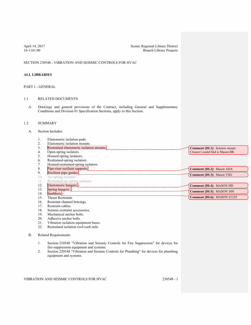
April 14, 2017 Scenic Regional Library District
16-1161.00 Branch Library Projects
VIBRATION AND SEISMIC CONTROLS FOR HVAC 230548 - 1
SECTION 230548 - VIBRATION AND SEISMIC CONTROLS FOR HVAC
ALL LIBRARIES
PART 1 - GENERAL
1.1 RELATED DOCUMENTS
A. Drawings and general provisions of the Contract, including General and Supplementary
Conditions and Division 01 Specification Sections, apply to this Section.
1.2 SUMMARY
A. Section Includes:
1. Elastomeric isolation pads.
2. Elastomeric isolation mounts.
3. Restrained elastomeric isolation mounts.
4. Open-spring isolators
5. Housed-spring isolators.
6. Restrained-spring isolators.
7. Housed-restrained-spring isolators.
8. Pipe-riser resilient supports.
9. Resilient pipe guides.
10. Air-spring isolators.
11. Restrained-air-spring isolators.
12. Elastomeric hangers. -
13. Spring hangers. -
14. Snubbers. –
15. Thrust Restraints
16. Restraint channel bracings.
17. Restraint cables.
18. Seismic-restraint accessories.
19. Mechanical anchor bolts.
20. Adhesive anchor bolts.
21. Vibration isolation equipment bases.
22. Restrained isolation roof-curb rails.
B. Related Requirements:
1. Section 210548 "Vibration and Seismic Controls for Fire Suppression" for devices for
fire-suppression equipment and systems.
2. Section 220548 "Vibration and Seismic Controls for Plumbing" for devices for plumbing
equipment and systems.
Comment [DL1]: Seismic mount.
Closest I could find is Mason BR.
Comment [DL2]: Mason ADA
Comment [DL3]: Mason VSG
Comment [DL4]: MASON HD
Comment [DL5]: MASON 30N
Comment [DL6]: MASON Z1225
April 14, 2017 Scenic Regional Library District
16-1161.00 Branch Library Projects
VIBRATION AND SEISMIC CONTROLS FOR HVAC 230548 - 2
1.3 DEFINITIONS
A. IBC: International Building Code.
B. ICC-ES: ICC-Evaluation Service.
C. OSHPD: Office of Statewide Health Planning & Development (for the State of California).
1.4 ACTION SUBMITTALS
A. Product Data: For each type of product.
1. Include rated load, rated deflection, and overload capacity for each vibration isolation
device.
2. Illustrate and indicate style, material, strength, fastening provision, and finish for each
type and size of vibration isolation device and seismic-restraint component required.
a. Tabulate types and sizes of seismic restraints, complete with report numbers and
rated strength in tension and shear as evaluated by [an evaluation service
member of ICC-ES] [OSHPD] [an agency acceptable to authorities having
jurisdiction].
b. Annotate to indicate application of each product submitted and compliance with
requirements.
3. Interlocking Snubbers: Include ratings for horizontal, vertical, and combined loads.
B. Shop Drawings:
1. Detail fabrication and assembly of equipment bases. Detail fabrication including
anchorages and attachments to structure and to supported equipment. Include adjustable
motor bases, rails, and frames for equipment mounting.
2. Vibration Isolation Base Details: Detail fabrication including anchorages and
attachments to structure and to supported equipment. Include adjustable motor bases,
rails, and frames for equipment mounting.
C. Delegated-Design Submittal: For each vibration isolation and seismic-restraint device.
1. Include design calculations and details for selecting vibration isolators, seismic restraints,
and vibration isolation bases complying with performance requirements, design criteria,
and analysis data signed and sealed by the qualified professional engineer responsible for
their preparation.
2. Design Calculations: Calculate static and dynamic loading due to equipment weight,
operation, and seismic[ and wind] forces required to select vibration isolators and
seismic[ and wind] restraints and for designing vibration isolation bases.
a. Coordinate design calculations with wind load calculations required for equipment
mounted outdoors. Comply with requirements in other Sections for equipment
mounted outdoors.
April 14, 2017 Scenic Regional Library District
16-1161.00 Branch Library Projects
VIBRATION AND SEISMIC CONTROLS FOR HVAC 230548 - 3
3. Riser Supports: Include riser diagrams and calculations showing anticipated expansion
and contraction at each support point, initial and final loads on building structure, spring
deflection changes, and seismic loads. Include certification that riser system was
examined for excessive stress and that none exists.
4. Seismic[- and Wind]-Restraint Details:
a. Design Analysis: To support selection and arrangement of seismic[ and wind]
restraints. Include calculations of combined tensile and shear loads.
b. Details: Indicate fabrication and arrangement. Detail attachments of restraints to
the restrained items and to the structure. Show attachment locations, methods, and
spacings. Identify components, list their strengths, and indicate directions and
values of forces transmitted to the structure during seismic events. Indicate
association with vibration isolation devices.
c. Coordinate seismic-restraint and vibration isolation details with wind-restraint
details required for equipment mounted outdoors. Comply with requirements in
other Sections for equipment mounted outdoors.
d. Preapproval and Evaluation Documentation: By [an evaluation service member
of ICC-ES] [OSHPD] [an agency acceptable to authorities having
jurisdiction], showing maximum ratings of restraint items and the basis for
approval (tests or calculations).
1.5 INFORMATIONAL SUBMITTALS
A. Coordination Drawings: Show coordination of vibration isolation device installation and
seismic bracing for HVAC piping and equipment with other systems and equipment in the
vicinity, including other supports and restraints, if any.
B. Qualification Data: For [professional engineer] [and] [testing agency].
C. Welding certificates.
D. Air-Mounting System Performance Certification: Include natural frequency, load, and damping
test data[ performed by an independent agency].
E. Field quality-control reports.
1.6 CLOSEOUT SUBMITTALS
A. Operation and Maintenance Data: For [air-spring mounts] [and] [restrained-air-spring
mounts] to include in operation and maintenance manuals.
1.7 QUALITY ASSURANCE
A. Testing Agency Qualifications: An independent agency, with the experience and capability to
conduct the testing indicated, that is an NRTL as defined by OSHA in 29 CFR 1910.7 and that
is acceptable to authorities having jurisdiction.
April 14, 2017 Scenic Regional Library District
16-1161.00 Branch Library Projects
VIBRATION AND SEISMIC CONTROLS FOR HVAC 230548 - 4
B. Comply with seismic-restraint requirements in the IBC unless requirements in this Section are
more stringent.
C. Welding Qualifications: Qualify procedures and personnel according to AWS D1.1/D1.1M,
"Structural Welding Code - Steel."
D. Seismic-restraint devices shall have horizontal and vertical load testing and analysis and shall
bear anchorage preapproval OPA number from OSHPD, preapproval by ICC-ES, or
preapproval by another agency acceptable to authorities having jurisdiction, showing maximum
seismic-restraint ratings. Ratings based on independent testing are preferred to ratings based on
calculations. If preapproved ratings are unavailable, submittals based on independent testing
are preferred. Calculations (including combining shear and tensile loads) to support seismic-
restraint designs must be signed and sealed by a qualified professional engineer.
PART 2 - PRODUCTS
2.1 PERFORMANCE REQUIREMENTS
A. Wind-Restraint Loading:
1. Basic Wind Speed: <Insert value>.
2. Building Classification Category: [I] [II] [III] [IV].
3. Minimum 10 lb/sq. ft. (48.8 kg/sq. m) multiplied by maximum area of HVAC component
projected on vertical plane normal to wind direction, and 45 degrees either side of
normal.
B. Seismic-Restraint Loading:
1. Site Class as Defined in the IBC: [A] [B] [C] [D] [E] [F].
2. Assigned Seismic Use Group or Building Category as Defined in the IBC: [I] [II] [III].
a. Component Importance Factor: [1.0] [1.5] <Insert value>.
b. Component Response Modification Factor: [1.5] [2.5] [3.5] [5.0] <Insert value>.
c. Component Amplification Factor: [1.0] [2.5] <Insert value>.
3. Design Spectral Response Acceleration at Short Periods (0.2 Second): <Insert
number>.
4. Design Spectral Response Acceleration at 1.0-Second Period: <Insert number>.
5. Rated strengths, features, and applications shall be as defined in reports by [an
evaluation service member of ICC-ES] [OSHPD] [an agency acceptable to
authorities having jurisdiction].
a. Structural Safety Factor: Allowable strength in tension, shear, and pullout force of
components shall be at least [four] <Insert number> times the maximum seismic
forces to which they are subjected.
April 14, 2017 Scenic Regional Library District
16-1161.00 Branch Library Projects
VIBRATION AND SEISMIC CONTROLS FOR HVAC 230548 - 5
2.2 ELASTOMERIC ISOLATION PADS
A. Elastomeric Isolation Pads: <Insert drawing designation>.
1. Manufacturers: Subject to compliance with requirements, [provide products by the
following] [provide products by one of the following] [available manufacturers
offering products that may be incorporated into the Work include, but are not
limited to, the following]:
2. Basis-of-Design Product: Subject to compliance with requirements, provide [product
indicated on Drawings] <Insert manufacturer's name; product name or
designation> or comparable product by one of the following:
a. Ace Mountings Co., Inc.
b. California Dynamics Corporation.
c. Isolation Technology, Inc.
d. Kinetics Noise Control, Inc.
e. Mason Industries, Inc.
f. Vibration Eliminator Co., Inc.
g. Vibration Isolation.
h. Vibration Mountings & Controls, Inc.
i. <Insert manufacturer's name>.
3. Fabrication: Single or multiple layers of sufficient durometer stiffness for uniform
loading over pad area.
4. Size: Factory or field cut to match requirements of supported equipment.
5. Pad Material: Oil and water resistant with elastomeric properties.
6. Surface Pattern: [Smooth] [Ribbed] [Waffle] pattern.
7. Infused nonwoven cotton or synthetic fibers.
8. Load-bearing metal plates adhered to pads.
9. Sandwich-Core Material: [Resilient] [and] [elastomeric] <Insert compound>.
a. Surface Pattern: [Smooth] [Ribbed] [Waffle] pattern.
b. Infused nonwoven cotton or synthetic fibers.
2.3 ELASTOMERIC ISOLATION MOUNTS
A. Double-Deflection, Elastomeric Isolation Mounts: <Insert drawing designation>.
1. Manufacturers: Subject to compliance with requirements, [provide products by the
following] [provide products by one of the following] [available manufacturers
offering products that may be incorporated into the Work include, but are not
limited to, the following]:
2. Basis-of-Design Product: Subject to compliance with requirements, provide [product
indicated on Drawings] <Insert manufacturer's name; product name or
designation> or comparable product by one of the following:
a. Ace Mountings Co., Inc.
b. California Dynamics Corporation.
c. Isolation Technology, Inc.
d. Kinetics Noise Control, Inc.
April 14, 2017 Scenic Regional Library District
16-1161.00 Branch Library Projects
VIBRATION AND SEISMIC CONTROLS FOR HVAC 230548 - 6
e. Mason Industries, Inc.
f. Vibration Eliminator Co., Inc.
g. Vibration Isolation.
h. Vibration Mountings & Controls, Inc.
i. <Insert manufacturer's name>.
3. Mounting Plates:
a. Top Plate: Encapsulated steel load transfer top plates, factory drilled and
threaded[ with threaded studs or bolts].
b. Baseplate: Encapsulated steel bottom plates with holes provided for anchoring to
support structure.
4. Elastomeric Material: Molded, oil-resistant rubber, neoprene, or other elastomeric
material.
2.4 RESTRAINED ELASTOMERIC ISOLATION MOUNTS
A. Restrained Elastomeric Isolation Mounts: <Insert drawing designation>.
1. Manufacturers: Subject to compliance with requirements, [provide products by the
following] [provide products by one of the following] [available manufacturers
offering products that may be incorporated into the Work include, but are not
limited to, the following]:
2. Basis-of-Design Product: Subject to compliance with requirements, provide [product
indicated on Drawings] <Insert manufacturer's name; product name or
designation> or comparable product by one of the following:
a. Ace Mountings Co., Inc.
b. California Dynamics Corporation.
c. Isolation Technology, Inc.
d. Kinetics Noise Control, Inc.
e. Mason Industries, Inc.
f. Vibration Eliminator Co., Inc.
g. Vibration Isolation.
h. Vibration Mountings & Controls, Inc.
i. <Insert manufacturer's name>.
3. Description: All-directional isolator with seismic restraints containing two separate and
opposing elastomeric elements that prevent central threaded element and attachment
hardware from contacting the housing during normal operation.
a. Housing: Cast-ductile iron or welded steel.
b. Elastomeric Material: Molded, oil-resistant rubber, neoprene, or other elastomeric
material.
2.5 OPEN-SPRING ISOLATORS
A. Freestanding, Laterally Stable, Open-Spring Isolators: <Insert drawing designation>.
April 14, 2017 Scenic Regional Library District
16-1161.00 Branch Library Projects
VIBRATION AND SEISMIC CONTROLS FOR HVAC 230548 - 7
1. Manufacturers: Subject to compliance with requirements, [provide products by the
following] [provide products by one of the following] [available manufacturers
offering products that may be incorporated into the Work include, but are not
limited to, the following]:
2. Basis-of-Design Product: Subject to compliance with requirements, provide [product
indicated on Drawings] <Insert manufacturer's name; product name or
designation> or comparable product by one of the following:
a. Ace Mountings Co., Inc.
b. California Dynamics Corporation.
c. Isolation Technology, Inc.
d. Kinetics Noise Control, Inc.
e. Mason Industries, Inc.
f. Vibration Eliminator Co., Inc.
g. Vibration Isolation.
h. Vibration Mountings & Controls, Inc.
i. <Insert manufacturer's name>.
3. Outside Spring Diameter: Not less than 80 percent of the compressed height of the
spring at rated load.
4. Minimum Additional Travel: 50 percent of the required deflection at rated load.
5. Lateral Stiffness: More than 80 percent of rated vertical stiffness.
6. Overload Capacity: Support 200 percent of rated load, fully compressed, without
deformation or failure.
7. Baseplates: Factory-drilled steel plate for bolting to structure with an elastomeric isolator
pad attached to the underside. Baseplates shall limit floor load to 500 psig (3447 kPa).
8. Top Plate and Adjustment Bolt: Threaded top plate with adjustment bolt and cap screw
to fasten and level equipment.
2.6 HOUSED-SPRING ISOLATORS
A. Freestanding, Laterally Stable, Open-Spring Isolators in Two-Part Telescoping Housing:
<Insert drawing designation>.
1. Manufacturers: Subject to compliance with requirements, [provide products by the
following] [provide products by one of the following] [available manufacturers
offering products that may be incorporated into the Work include, but are not
limited to, the following]:
2. Basis-of-Design Product: Subject to compliance with requirements, provide [product
indicated on Drawings] <Insert manufacturer's name; product name or
designation> or comparable product by one of the following:
a. Ace Mountings Co., Inc.
b. California Dynamics Corporation.
c. Isolation Technology, Inc.
d. Kinetics Noise Control, Inc.
e. Mason Industries, Inc.
f. Vibration Eliminator Co., Inc.
g. Vibration Isolation.
h. Vibration Mountings & Controls, Inc.
April 14, 2017 Scenic Regional Library District
16-1161.00 Branch Library Projects
VIBRATION AND SEISMIC CONTROLS FOR HVAC 230548 - 8
i. <Insert manufacturer's name>.
3. Outside Spring Diameter: Not less than 80 percent of the compressed height of the
spring at rated load.
4. Minimum Additional Travel: 50 percent of the required deflection at rated load.
5. Lateral Stiffness: More than 80 percent of rated vertical stiffness.
6. Overload Capacity: Support 200 percent of rated load, fully compressed, without
deformation or failure.
7. Two-Part Telescoping Housing: A steel top and bottom frame separated by an
elastomeric material and enclosing the spring isolators.
a. Drilled base housing for bolting to structure with an elastomeric isolator pad
attached to the underside. Bases shall limit floor load to 500 psig (3447 kPa).
b. Top housing with [attachment and leveling bolt] [threaded mounting holes and
internal leveling device] [elastomeric pad].
2.7 RESTRAINED-SPRING ISOLATORS
A. Freestanding, Laterally Stable, Open-Spring Isolators with Vertical-Limit Stop Restraint:
<Insert drawing designation>.
1. Manufacturers: Subject to compliance with requirements, [provide products by the
following] [provide products by one of the following] [available manufacturers
offering products that may be incorporated into the Work include, but are not
limited to, the following]:
2. Basis-of-Design Product: Subject to compliance with requirements, provide [product
indicated on Drawings] <Insert manufacturer's name; product name or
designation> or comparable product by one of the following:
a. Ace Mountings Co., Inc.
b. California Dynamics Corporation.
c. Isolation Technology, Inc.
d. Kinetics Noise Control, Inc.
e. Mason Industries, Inc.
f. Vibration Eliminator Co., Inc.
g. Vibration Isolation.
h. Vibration Mountings & Controls, Inc.
i. <Insert manufacturer's name>.
3. Housing: Steel housing with vertical-limit stops to prevent spring extension due to
weight being removed.
a. Base with holes for bolting to structure with an elastomeric isolator pad attached to
the underside. Bases shall limit floor load to 500 psig (3447 kPa).
b. Top plate with [threaded mounting holes] [elastomeric pad].
c. Internal leveling bolt that acts as blocking during installation.
4. Restraint: Limit stop as required for equipment and authorities having jurisdiction.
5. Outside Spring Diameter: Not less than 80 percent of the compressed height of the
spring at rated load.
April 14, 2017 Scenic Regional Library District
16-1161.00 Branch Library Projects
VIBRATION AND SEISMIC CONTROLS FOR HVAC 230548 - 9
6. Minimum Additional Travel: 50 percent of the required deflection at rated load.
7. Lateral Stiffness: More than 80 percent of rated vertical stiffness.
8. Overload Capacity: Support 200 percent of rated load, fully compressed, without
deformation or failure.
2.8 HOUSED-RESTRAINED-SPRING ISOLATORS
A. Freestanding, Steel, Open-Spring Isolators with Vertical-Limit Stop Restraint in Two-Part
Telescoping Housing: <Insert drawing designation>.
1. Manufacturers: Subject to compliance with requirements, [provide products by the
following] [provide products by one of the following] [available manufacturers
offering products that may be incorporated into the Work include, but are not
limited to, the following]:
2. Basis-of-Design Product: Subject to compliance with requirements, provide [product
indicated on Drawings] <Insert manufacturer's name; product name or
designation> or comparable product by one of the following:
a. Ace Mountings Co., Inc.
b. California Dynamics Corporation.
c. Isolation Technology, Inc.
d. Kinetics Noise Control, Inc.
e. Mason Industries, Inc.
f. Vibration Eliminator Co., Inc.
g. Vibration Isolation.
h. Vibration Mountings & Controls, Inc.
i. <Insert manufacturer's name>.
3. Two-Part Telescoping Housing: A steel top and bottom frame separated by an
elastomeric material and enclosing the spring isolators. Housings are equipped with
[adjustable] [non-adjustable] snubbers to limit vertical movement.
a. Drilled base housing for bolting to structure with an elastomeric isolator pad
attached to the underside. Bases shall limit floor load to 500 psig (3447 kPa).
b. Threaded top housing with adjustment bolt and cap screw to fasten and level
equipment.
4. Outside Spring Diameter: Not less than 80 percent of the compressed height of the
spring at rated load.
5. Minimum Additional Travel: 50 percent of the required deflection at rated load.
6. Lateral Stiffness: More than 80 percent of rated vertical stiffness.
7. Overload Capacity: Support 200 percent of rated load, fully compressed, without
deformation or failure.
2.9 PIPE-RISER RESILIENT SUPPORT
A. Description: All-directional, acoustical pipe anchor consisting of two steel tubes separated by a
minimum 1/2-inch- (13-mm-) thick neoprene <Insert drawing designation>.
April 14, 2017 Scenic Regional Library District
16-1161.00 Branch Library Projects
VIBRATION AND SEISMIC CONTROLS FOR HVAC 230548 - 10
1. Vertical-Limit Stops: Steel and neoprene vertical-limit stops arranged to prevent vertical
travel in both directions.
2. Maximum Load Per Support: 500 psig (3.45 MPa)on isolation material providing equal
isolation in all directions.
2.10 RESILIENT PIPE GUIDES
A. Description: Telescopic arrangement of two steel tubes or post and sleeve arrangement
separated by a minimum 1/2-inch- (13-mm-) thick neoprene <Insert drawing designation>.
1. Factory-Set Height Guide with Shear Pin: Shear pin shall be removable and reinsertable
to allow for selection of pipe movement. Guides shall be capable of motion to meet
location requirements.
2.11 AIR-SPRING ISOLATORS
A. Freestanding, Single or Multiple, Compressed-Air Bellows: <Insert drawing designation>.
1. Manufacturers: Subject to compliance with requirements, [provide products by the
following] [provide products by one of the following] [available manufacturers
offering products that may be incorporated into the Work include, but are not
limited to, the following]:
2. Basis-of-Design Product: Subject to compliance with requirements, provide [product
indicated on Drawings] <Insert manufacturer's name; product name or
designation> or comparable product by one of the following:
a. Firestone Industrial Products Company.
b. Mason Industries, Inc.
c. <Insert manufacturer's name>.
3. Bellows Assembly: Upper and lower powder-coated steel sections connected by a
replaceable, flexible, nylon-reinforced neoprene bellows or similar elastomeric material.
4. Maximum Natural Frequency: 3 Hz.
5. Operating Pressure Range: 25 to 100 psig (172 to 690 kPa).
6. Burst Pressure: At least three times manufacturer's published maximum operating
pressure.
7. Tank valves.
2.12 RESTRAINED-AIR-SPRING ISOLATORS
A. Freestanding, Single or Multiple, Compressed-Air Bellows with Vertical-Limit Stop Restraint:
<Insert drawing designation>.
1. Manufacturers: Subject to compliance with requirements, [provide products by the
following] [provide products by one of the following] [available manufacturers
offering products that may be incorporated into the Work include, but are not
limited to, the following]:
April 14, 2017 Scenic Regional Library District
16-1161.00 Branch Library Projects
VIBRATION AND SEISMIC CONTROLS FOR HVAC 230548 - 11
2. Basis-of-Design Product: Subject to compliance with requirements, provide [product
indicated on Drawings] <Insert manufacturer's name; product name or
designation> or comparable product by one of the following:
a. Firestone Industrial Products Company.
b. Mason Industries, Inc.
c. <Insert manufacturer's name>.
3. Housing: Steel housing with vertical-limit stops to prevent spring extension due to
weight being removed.
a. Base with holes for bolting to structure with an elastomeric isolator pad attached to
the underside. Bases shall limit floor load to 500 psig (3447 kPa).
b. Top plate with [threaded mounting holes] [elastomeric pad].
c. Internal leveling bolt that acts as blocking during installation.
4. Restraint: Limit stop as required for equipment and authorities having jurisdiction.
5. Outside Spring Diameter: Not less than 80 percent of the compressed height of the
spring at rated load.
6. Minimum Additional Travel: 50 percent of the required deflection at rated load.
7. Lateral Stiffness: More than 80 percent of rated vertical stiffness.
8. Overload Capacity: Support 200 percent of rated load, fully compressed, without
deformation or failure.
9. Bellows Assembly: Upper and lower powder-coated steel sections connected by a
replaceable, flexible, nylon-reinforced neoprene bellows or similar elastomeric material.
10. Maximum Natural Frequency: 3 Hz.
11. Operating Pressure Range: 25 to 100 psig (172 to 690 kPa).
12. Burst Pressure: At least three times manufacturer's published maximum operating
pressure.
13. Tank valves.
2.13 ELASTOMERIC HANGERS
A. Elastomeric Mount in a Steel Frame with Upper and Lower Steel Hanger Rods: <Insert
drawing designation>.
1. Manufacturers: Subject to compliance with requirements, [provide products by the
following] [provide products by one of the following] [available manufacturers
offering products that may be incorporated into the Work include, but are not
limited to, the following]:
2. Basis-of-Design Product: Subject to compliance with requirements, provide [product
indicated on Drawings] <Insert manufacturer's name; product name or
designation> or comparable product by one of the following:
a. Ace Mountings Co., Inc.
b. California Dynamics Corporation.
c. Isolation Technology, Inc.
d. Kinetics Noise Control, Inc.
e. Mason Industries, Inc.
f. Vibration Eliminator Co., Inc.
April 14, 2017 Scenic Regional Library District
16-1161.00 Branch Library Projects
VIBRATION AND SEISMIC CONTROLS FOR HVAC 230548 - 12
g. Vibration Mountings & Controls, Inc.
h. <Insert manufacturer's name>.
3. Frame: Steel, fabricated with a connection for an upper threaded hanger rod and an
opening on the underside to allow for a maximum of 30 degrees of angular lower hanger-
rod misalignment without binding or reducing isolation efficiency.
4. Dampening Element: Molded, oil-resistant rubber, neoprene, or other elastomeric
material with a projecting bushing for the underside opening preventing steel to steel
contact.
2.14 SPRING HANGERS
A. Combination Coil-Spring and Elastomeric-Insert Hanger with Spring and Insert in
Compression: <Insert drawing designation>.
1. Manufacturers: Subject to compliance with requirements, [provide products by the
following] [provide products by one of the following] [available manufacturers
offering products that may be incorporated into the Work include, but are not
limited to, the following]:
2. Basis-of-Design Product: Subject to compliance with requirements, provide [product
indicated on Drawings] <Insert manufacturer's name; product name or
designation> or comparable product by one of the following:
a. Ace Mountings Co., Inc.
b. California Dynamics Corporation.
c. Kinetics Noise Control, Inc.
d. Mason Industries, Inc.
e. Vibration Eliminator Co., Inc.
f. Vibration Isolation.
g. Vibration Mountings & Controls, Inc.
h. <Insert manufacturer's name>.
3. Frame: Steel, fabricated for connection to threaded hanger rods and to allow for a
maximum of 30 degrees of angular hanger-rod misalignment without binding or reducing
isolation efficiency.
4. Outside Spring Diameter: Not less than 80 percent of the compressed height of the
spring at rated load.
5. Minimum Additional Travel: 50 percent of the required deflection at rated load.
6. Lateral Stiffness: More than 80 percent of rated vertical stiffness.
7. Overload Capacity: Support 200 percent of rated load, fully compressed, without
deformation or failure.
8. Elastomeric Element: Molded, oil-resistant rubber or neoprene. Steel-washer-reinforced
cup to support spring and bushing projecting through bottom of frame.
9. Adjustable Vertical Stop: Steel washer with neoprene washer "up-stop" on lower
threaded rod.
10. Self-centering hanger-rod cap to ensure concentricity between hanger rod and support
spring coil.
April 14, 2017 Scenic Regional Library District
16-1161.00 Branch Library Projects
VIBRATION AND SEISMIC CONTROLS FOR HVAC 230548 - 13
2.15 SNUBBERS
A. Manufacturers: Subject to compliance with requirements, [provide products by the following]
[provide products by one of the following] [available manufacturers offering products that
may be incorporated into the Work include, but are not limited to, the following]:
B. Basis-of-Design Product: Subject to compliance with requirements, provide [product
indicated on Drawings] <Insert manufacturer's name; product name or designation> or
comparable product by one of the following:
1. Kinetics Noise Control, Inc.
2. Mason Industries, Inc.
3. Vibration Mountings & Controls, Inc.
4. <Insert manufacturer's name>.
C. Description: Factory fabricated using welded structural-steel shapes and plates, anchor bolts,
and replaceable resilient isolation washers and bushings.
1. Anchor bolts for attaching to concrete shall be seismic-rated, drill-in, and stud-wedge or
female-wedge type.
2. Resilient Isolation Washers and Bushings: Oil- and water-resistant neoprene.
3. Maximum 1/4-inch (6-mm) air gap, and minimum 1/4-inch- (6-mm-) thick resilient
cushion.
2.16 THRUST RESTRAINTS
A. Description: Thrust Restraints shall consist of high deflection, large diameter, laterally stable
steel coil springs assembled into a threaded rod and angle bracket assembly. Coil springs shall
have a lateral spring stiffness greater than 1.0 times the rated vertical stiffness to assure coil
stability. Coil springs shall provide a minimum of 50% overload deflection capability to solid
and shall be safe when temporarily loaded to solid capacity. Coil springs shall be polyester
powder coated for corrosion protection and shall demonstrate successful completion of a 1000
hour salt spray test per ASTM Standard B-117. Thrust Restraints shall feature molded neoprene
end load plate assemblies for light capacities or stamped steel end cups for heavier capacities.
Thrust Restraints shall include threaded adjustment rod with zinc-plated hardware, and shall
include primer painted fan and ductwork mounting bracket angles, bracket back-up plates, and
complete fan / ductwork attachment hardware.
2.17 RESTRAINT CHANNEL BRACINGS
A. Manufacturers: Subject to compliance with requirements, [provide products by the following]
[provide products by one of the following] [available manufacturers offering products that
may be incorporated into the Work include, but are not limited to, the following]:
B. Basis-of-Design Product: Subject to compliance with requirements, provide [product
indicated on Drawings] <Insert manufacturer's name; product name or designation> or
comparable product by one of the following:
Comment [DL7]: KINETICS NOISE
CONTROL MODEL HSR
April 14, 2017 Scenic Regional Library District
16-1161.00 Branch Library Projects
VIBRATION AND SEISMIC CONTROLS FOR HVAC 230548 - 14
1. Cooper B-Line, Inc.
2. Hilti, Inc.
3. Mason Industries, Inc.
4. Unistrut.
5. <Insert manufacturer's name>.
C. Description: MFMA-4, shop- or field-fabricated bracing assembly made of slotted steel
channels with accessories for attachment to braced component at one end and to building
structure at the other end and other matching components and with corrosion-resistant coating;
rated in tension, compression, and torsion forces.
2.18 RESTRAINT CABLES
A. Manufacturers: Subject to compliance with requirements, [provide products by the following]
[provide products by one of the following] [available manufacturers offering products that
may be incorporated into the Work include, but are not limited to, the following]:
B. Basis-of-Design Product: Subject to compliance with requirements, provide [product
indicated on Drawings] <Insert manufacturer's name; product name or designation> or
comparable product by one of the following:
1. Kinetics Noise Control, Inc.
2. Loos & Co., Inc.
3. Vibration Mountings & Controls, Inc.
4. <Insert manufacturer's name>.
C. Restraint Cables: [ASTM A 603 galvanized] [ASTM A 492 stainless]-steel cables. End
connections made of steel assemblies with thimbles, brackets, swivel, and bolts designed for
restraining cable service; with a minimum of two clamping bolts for cable engagement.
2.19 SEISMIC-RESTRAINT ACCESSORIES
A. Manufacturers: Subject to compliance with requirements, [provide products by the following]
[provide products by one of the following] [available manufacturers offering products that
may be incorporated into the Work include, but are not limited to, the following]:
B. Basis-of-Design Product: Subject to compliance with requirements, provide [product
indicated on Drawings] <Insert manufacturer's name; product name or designation> or
comparable product by one of the following:
1. Cooper B-Line, Inc.
2. Kinetics Noise Control, Inc.
3. Mason Industries, Inc.
4. TOLCO.
5. <Insert manufacturer's name>.
C. Hanger-Rod Stiffener: [Steel tube or steel slotted-support-system sleeve with internally
bolted connections] [Reinforcing steel angle clamped] to hanger rod.
April 14, 2017 Scenic Regional Library District
16-1161.00 Branch Library Projects
VIBRATION AND SEISMIC CONTROLS FOR HVAC 230548 - 15
D. Hinged and Swivel Brace Attachments: Multifunctional steel connectors for attaching hangers
to [rigid channel bracings] [and] [restraint cables].
E. Bushings for Floor-Mounted Equipment Anchor Bolts: Neoprene bushings designed for rigid
equipment mountings, and matched to type and size of anchor bolts and studs.
F. Bushing Assemblies for Wall-Mounted Equipment Anchorage: Assemblies of neoprene
elements and steel sleeves designed for rigid equipment mountings, and matched to type and
size of attachment devices used.
G. Resilient Isolation Washers and Bushings: One-piece, molded, oil- and water-resistant
neoprene, with a flat washer face.
2.20 MECHANICAL ANCHOR BOLTS
A. Manufacturers: Subject to compliance with requirements, [provide products by the following]
[provide products by one of the following] [available manufacturers offering products that
may be incorporated into the Work include, but are not limited to, the following]:
B. Basis-of-Design Product: Subject to compliance with requirements, provide [product
indicated on Drawings] <Insert manufacturer's name; product name or designation> or
comparable product by one of the following:
1. Cooper B-Line, Inc.
2. Hilti, Inc.
3. Kinetics Noise Control, Inc.
4. Mason Industries, Inc.
5. <Insert manufacturer's name>.
C. Mechanical Anchor Bolts: Drilled-in and stud-wedge or female-wedge type in zinc-coated steel
for interior applications and stainless steel for exterior applications. Select anchor bolts with
strength required for anchor and as tested according to ASTM E 488.
2.21 ADHESIVE ANCHOR BOLTS
A. Manufacturers: Subject to compliance with requirements, [provide products by the following]
[provide products by one of the following] [available manufacturers offering products that
may be incorporated into the Work include, but are not limited to, the following]:
B. Basis-of-Design Product: Subject to compliance with requirements, provide [product
indicated on Drawings] <Insert manufacturer's name; product name or designation> or
comparable product by one of the following:
1. Hilti, Inc.
2. Kinetics Noise Control, Inc.
3. Mason Industries, Inc.
4. <Insert manufacturer's name>.
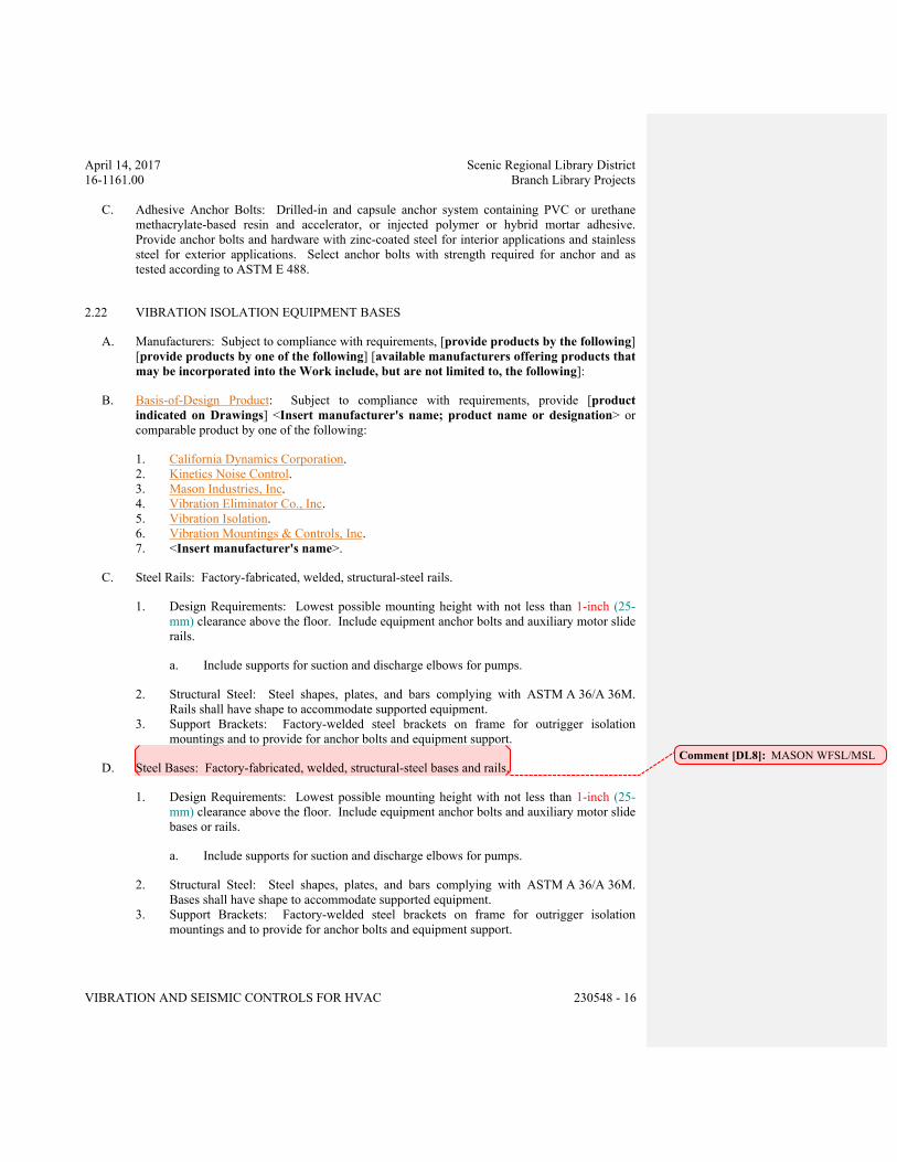
April 14, 2017 Scenic Regional Library District
16-1161.00 Branch Library Projects
VIBRATION AND SEISMIC CONTROLS FOR HVAC 230548 - 16
C. Adhesive Anchor Bolts: Drilled-in and capsule anchor system containing PVC or urethane
methacrylate-based resin and accelerator, or injected polymer or hybrid mortar adhesive.
Provide anchor bolts and hardware with zinc-coated steel for interior applications and stainless
steel for exterior applications. Select anchor bolts with strength required for anchor and as
tested according to ASTM E 488.
2.22 VIBRATION ISOLATION EQUIPMENT BASES
A. Manufacturers: Subject to compliance with requirements, [provide products by the following]
[provide products by one of the following] [available manufacturers offering products that
may be incorporated into the Work include, but are not limited to, the following]:
B. Basis-of-Design Product: Subject to compliance with requirements, provide [product
indicated on Drawings] <Insert manufacturer's name; product name or designation> or
comparable product by one of the following:
1. California Dynamics Corporation.
2. Kinetics Noise Control.
3. Mason Industries, Inc.
4. Vibration Eliminator Co., Inc.
5. Vibration Isolation.
6. Vibration Mountings & Controls, Inc.
7. <Insert manufacturer's name>.
C. Steel Rails: Factory-fabricated, welded, structural-steel rails.
1. Design Requirements: Lowest possible mounting height with not less than 1-inch (25-
mm) clearance above the floor. Include equipment anchor bolts and auxiliary motor slide
rails.
a. Include supports for suction and discharge elbows for pumps.
2. Structural Steel: Steel shapes, plates, and bars complying with ASTM A 36/A 36M.
Rails shall have shape to accommodate supported equipment.
3. Support Brackets: Factory-welded steel brackets on frame for outrigger isolation
mountings and to provide for anchor bolts and equipment support.
D. Steel Bases: Factory-fabricated, welded, structural-steel bases and rails.
1. Design Requirements: Lowest possible mounting height with not less than 1-inch (25-
mm) clearance above the floor. Include equipment anchor bolts and auxiliary motor slide
bases or rails.
a. Include supports for suction and discharge elbows for pumps.
2. Structural Steel: Steel shapes, plates, and bars complying with ASTM A 36/A 36M.
Bases shall have shape to accommodate supported equipment.
3. Support Brackets: Factory-welded steel brackets on frame for outrigger isolation
mountings and to provide for anchor bolts and equipment support.
Comment [DL8]: MASON WFSL/MSL
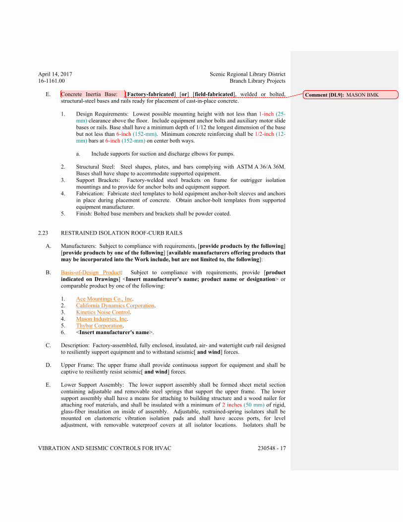
April 14, 2017 Scenic Regional Library District
16-1161.00 Branch Library Projects
VIBRATION AND SEISMIC CONTROLS FOR HVAC 230548 - 17
E. Concrete Inertia Base: [Factory-fabricated] [or] [field-fabricated], welded or bolted,
structural-steel bases and rails ready for placement of cast-in-place concrete.
1. Design Requirements: Lowest possible mounting height with not less than 1-inch (25-
mm) clearance above the floor. Include equipment anchor bolts and auxiliary motor slide
bases or rails. Base shall have a minimum depth of 1/12 the longest dimension of the base
but not less than 6-inch (152-mm). Minimum concrete reinforcing shall be 1/2-inch (12-
mm) bars at 6-inch (152-mm) on center both ways.
a. Include supports for suction and discharge elbows for pumps.
2. Structural Steel: Steel shapes, plates, and bars complying with ASTM A 36/A 36M.
Bases shall have shape to accommodate supported equipment.
3. Support Brackets: Factory-welded steel brackets on frame for outrigger isolation
mountings and to provide for anchor bolts and equipment support.
4. Fabrication: Fabricate steel templates to hold equipment anchor-bolt sleeves and anchors
in place during placement of concrete. Obtain anchor-bolt templates from supported
equipment manufacturer.
5. Finish: Bolted base members and brackets shall be powder coated.
2.23 RESTRAINED ISOLATION ROOF-CURB RAILS
A. Manufacturers: Subject to compliance with requirements, [provide products by the following]
[provide products by one of the following] [available manufacturers offering products that
may be incorporated into the Work include, but are not limited to, the following]:
B. Basis-of-Design Product: Subject to compliance with requirements, provide [product
indicated on Drawings] <Insert manufacturer's name; product name or designation> or
comparable product by one of the following:
1. Ace Mountings Co., Inc.
2. California Dynamics Corporation.
3. Kinetics Noise Control.
4. Mason Industries, Inc.
5. Thybar Corporation.
6. <Insert manufacturer's name>.
C. Description: Factory-assembled, fully enclosed, insulated, air- and watertight curb rail designed
to resiliently support equipment and to withstand seismic[ and wind] forces.
D. Upper Frame: The upper frame shall provide continuous support for equipment and shall be
captive to resiliently resist seismic[ and wind] forces.
E. Lower Support Assembly: The lower support assembly shall be formed sheet metal section
containing adjustable and removable steel springs that support the upper frame. The lower
support assembly shall have a means for attaching to building structure and a wood nailer for
attaching roof materials, and shall be insulated with a minimum of 2 inches (50 mm) of rigid,
glass-fiber insulation on inside of assembly. Adjustable, restrained-spring isolators shall be
mounted on elastomeric vibration isolation pads and shall have access ports, for level
adjustment, with removable waterproof covers at all isolator locations. Isolators shall be
Comment [DL9]: MASON BMK
April 14, 2017 Scenic Regional Library District
16-1161.00 Branch Library Projects
VIBRATION AND SEISMIC CONTROLS FOR HVAC 230548 - 18
located so they are accessible for adjustment at any time during the life of the installation
without interfering with the integrity of the roof.
F. Snubber Bushings: All-directional, elastomeric snubber bushings at least 1/4 inch (6 mm) thick.
G. Water Seal: Galvanized sheet metal with EPDM seals at corners, attached to upper support
frame, extending down past wood nailer of lower support assembly, and counterflashed over
roof materials.
PART 3 - EXECUTION
3.1 EXAMINATION
A. Examine areas and equipment to receive vibration isolation and seismic[- and wind]-control
devices for compliance with requirements for installation tolerances and other conditions
affecting performance of the Work.
B. Examine roughing-in of reinforcement and cast-in-place anchors to verify actual locations
before installation.
C. Proceed with installation only after unsatisfactory conditions have been corrected.
3.2 APPLICATIONS
A. Multiple Pipe Supports: Secure pipes to trapeze member with clamps approved for application
by [an evaluation service member of ICC-ES] [OSHPD] [an agency acceptable to
authorities having jurisdiction].
B. Hanger-Rod Stiffeners: Install hanger-rod stiffeners where indicated or scheduled on Drawings
to receive them and where required to prevent buckling of hanger rods due to seismic forces.
C. Strength of Support and Seismic-Restraint Assemblies: Where not indicated, select sizes of
components so strength is adequate to carry present and future static and seismic loads within
specified loading limits.
3.3 VIBRATION CONTROL AND SEISMIC-RESTRAINT DEVICE INSTALLATION
A. Coordinate the location of embedded connection hardware with supported equipment
attachment and mounting points and with requirements for concrete reinforcement and
formwork specified in [Section 033000 "Cast-in-Place Concrete."] [Section 033053
"Miscellaneous Cast-in-Place Concrete."]
B. Installation of vibration isolators must not cause any change of position of equipment, piping, or
ductwork resulting in stresses or misalignment.
C. Comply with requirements in Section 077200 "Roof Accessories" for installation of roof curbs,
equipment supports, and roof penetrations.
April 14, 2017 Scenic Regional Library District
16-1161.00 Branch Library Projects
VIBRATION AND SEISMIC CONTROLS FOR HVAC 230548 - 19
D. Equipment Restraints:
1. Install seismic snubbers on HVAC equipment mounted on vibration isolators. Locate
snubbers as close as possible to vibration isolators and bolt to equipment base and
supporting structure.
2. Install resilient bolt isolation washers on equipment anchor bolts where clearance
between anchor and adjacent surface exceeds 0.125 inch (3.2 mm).
3. Install seismic-restraint devices using methods approved by [an evaluation service
member of ICC-ES] [OSHPD] [an agency acceptable to authorities having
jurisdiction] that provides required submittals for component.
E. Piping Restraints:
1. Comply with requirements in MSS SP-127.
2. Space lateral supports a maximum of [40 feet (12 m)] <Insert dimension> o.c., and
longitudinal supports a maximum of [80 feet (24 m)] <Insert dimension> o.c.
3. Brace a change of direction longer than 12 feet (3.7 m).
F. Install cables so they do not bend across edges of adjacent equipment or building structure.
G. Install seismic-restraint devices using methods approved by [an evaluation service member of
ICC-ES] [OSHPD] [an agency acceptable to authorities having jurisdiction] that provides
required submittals for component.
H. Install bushing assemblies for anchor bolts for floor-mounted equipment, arranged to provide
resilient media between anchor bolt and mounting hole in concrete base.
I. Install bushing assemblies for mounting bolts for wall-mounted equipment, arranged to provide
resilient media where equipment or equipment-mounting channels are attached to wall.
J. Attachment to Structure: If specific attachment is not indicated, anchor bracing to structure at
flanges of beams, at upper truss chords of bar joists, or at concrete members.
K. Drilled-in Anchors:
1. Identify position of reinforcing steel and other embedded items prior to drilling holes for
anchors. Do not damage existing reinforcing or embedded items during coring or
drilling. Notify the structural engineer if reinforcing steel or other embedded items are
encountered during drilling. Locate and avoid prestressed tendons, electrical and
telecommunications conduit, and gas lines.
2. Do not drill holes in concrete or masonry until concrete, mortar, or grout has achieved
full design strength.
3. Wedge Anchors: Protect threads from damage during anchor installation. Heavy-duty
sleeve anchors shall be installed with sleeve fully engaged in the structural element to
which anchor is to be fastened.
4. Adhesive Anchors: Clean holes to remove loose material and drilling dust prior to
installation of adhesive. Place adhesive in holes proceeding from the bottom of the hole
and progressing toward the surface in such a manner as to avoid introduction of air
pockets in the adhesive.
5. Set anchors to manufacturer's recommended torque, using a torque wrench.
April 14, 2017 Scenic Regional Library District
16-1161.00 Branch Library Projects
VIBRATION AND SEISMIC CONTROLS FOR HVAC 230548 - 20
6. Install zinc-coated steel anchors for interior and stainless-steel anchors for exterior
applications.
3.4 ACCOMMODATION OF DIFFERENTIAL SEISMIC MOTION
A. Install flexible connections in piping where they cross seismic joints, where adjacent sections or
branches are supported by different structural elements, and where the connections terminate
with connection to equipment that is anchored to a different structural element from the one
supporting the connections as they approach equipment. Comply with requirements in
Section 232113 "Hydronic Piping" for piping flexible connections.
3.5 FIELD QUALITY CONTROL
A. Testing Agency: [Owner will engage] [Engage] a qualified testing agency to perform tests and
inspections.
B. Perform tests and inspections.
C. Tests and Inspections:
1. Provide evidence of recent calibration of test equipment by a testing agency acceptable to
authorities having jurisdiction.
2. Schedule test with Owner, through Architect, before connecting anchorage device to
restrained component (unless postconnection testing has been approved), and with at least
seven days' advance notice.
3. Obtain Architect's approval before transmitting test loads to structure. Provide temporary
load-spreading members.
4. Test at least [four] <Insert number> of each type and size of installed anchors and
fasteners selected by Architect.
5. Test to 90 percent of rated proof load of device.
6. Measure isolator restraint clearance.
7. Measure isolator deflection.
8. Verify snubber minimum clearances.
9. Test and adjust restrained-air-spring isolator controls and safeties.
D. Remove and replace malfunctioning units and retest as specified above.
E. Prepare test and inspection reports.
3.6 ADJUSTING
A. Adjust isolators after piping system is at operating weight.
B. Adjust limit stops on restrained-spring isolators to mount equipment at normal operating height.
After equipment installation is complete, adjust limit stops so they are out of contact during
normal operation.
April 14, 2017 Scenic Regional Library District
16-1161.00 Branch Library Projects
VIBRATION AND SEISMIC CONTROLS FOR HVAC 230548 - 21
3.7 AIR-SPRING ISOLATOR INSTALLATION
A. Independent Isolator Installation:
1. Install tank valve into each air isolator.
2. Inflate each isolator to [height] [and] [pressure] specified on Drawings.
B. Pressure-Regulated Isolator Installation:
1. Coordinate the constant pressure-regulated air supply to air springs with the requirements
for piping and connections specified in Section 221513 "General-Service Compressed-
Air Piping."
2. Connect all pressure regulators to a single dry, filtered [facility] [constant] air supply.
3. Inflate isolators to [height] [and] [or] [pressure] specified on Drawings.
3.8 VIBRATION ISOLATION EQUIPMENT BASES INSTALLATION
A. Coordinate the location of embedded connection hardware with supported equipment
attachment and mounting points and with requirements for concrete reinforcement and
formwork specified in [Section 033000 "Cast-in-Place Concrete."] [Section 033053,
"Miscellaneous Cast-in-Place Concrete."]
END OF SECTION 230548
April 14, 2017 Scenic Regional Library District
16-1161.00 Branch Library Projects
VIBRATION AND SEISMIC CONTROLS FOR HVAC 23 05 48 - 1
SECTION 23 05 48 - VIBRATION AND SEISMIC CONTROLS FOR HVAC
ALL LIBRARIES
PART 1 - GENERAL
1.1 RELATED DOCUMENTS
A. Drawings and general provisions of the Contract, including General and Supplementary
Conditions and Division 01 Specification Sections, apply to this Section.
1.2 SUMMARY
A. Section Includes:
1. Elastomeric isolation pads.
2. Elastomeric isolation mounts.
3. Restrained elastomeric isolation mounts.
4. Housed-spring isolators.
5. Restrained-spring isolators.
6. Housed-restrained-spring isolators.
7. Elastomeric hangers.
8. Spring hangers.
9. Snubbers.
10. Restraint channel bracings.
11. Restraint cables.
12. Seismic-restraint accessories.
B. Related Requirements:
1. Section 210548 "Vibration and Seismic Controls for Fire Suppression" for devices for
fire-suppression equipment and systems.
2. Section 220548 "Vibration and Seismic Controls for Plumbing" for devices for plumbing
equipment and systems.
1.3 DEFINITIONS
A. IBC: International Building Code.
B. ICC-ES: ICC-Evaluation Service.
C. OSHPD: Office of Statewide Health Planning & Development (for the State of California).
1.4 ACTION SUBMITTALS
A. Product Data: For each type of product.
April 14, 2017 Scenic Regional Library District
16-1161.00 Branch Library Projects
VIBRATION AND SEISMIC CONTROLS FOR HVAC 23 05 48 - 2
1. Include rated load, rated deflection, and overload capacity for each vibration isolation
device.
2. Illustrate and indicate style, material, strength, fastening provision, and finish for each
type and size of vibration isolation device and seismic-restraint component required.
a. Tabulate types and sizes of seismic restraints, complete with report numbers and
rated strength in tension and shear as evaluated by an agency acceptable to
authorities having jurisdiction.
b. Annotate to indicate application of each product submitted and compliance with
requirements.
3. Interlocking Snubbers: Include ratings for horizontal, vertical, and combined loads.
B. Shop Drawings:
1. Detail fabrication and assembly of equipment bases. Detail fabrication including
anchorages and attachments to structure and to supported equipment. Include adjustable
motor bases, rails, and frames for equipment mounting.
2. Vibration Isolation Base Details: Detail fabrication including anchorages and attachments
to structure and to supported equipment. Include adjustable motor bases, rails, and frames
for equipment mounting.
C. Delegated-Design Submittal: For each vibration isolation and seismic-restraint device.
1. Include design calculations and details for selecting vibration isolators, seismic restraints,
and vibration isolation bases complying with performance requirements, design criteria,
and analysis data signed and sealed by the qualified professional engineer responsible for
their preparation.
2. Design Calculations: Calculate static and dynamic loading due to equipment weight,
operation, and seismic and wind forces required to select vibration isolators and
seismic and wind restraints and for designing vibration isolation bases.
a. Coordinate design calculations with wind load calculations required for equipment
mounted outdoors. Comply with requirements in other Sections for equipment
mounted outdoors.
3. Seismic and Wind-Restraint Details:
a. Design Analysis: To support selection and arrangement of seismic and wind
restraints. Include calculations of combined tensile and shear loads.
b. Details: Indicate fabrication and arrangement. Detail attachments of restraints to
the restrained items and to the structure. Show attachment locations, methods, and
spacings. Identify components, list their strengths, and indicate directions and
values of forces transmitted to the structure during seismic events. Indicate
association with vibration isolation devices.
c. Coordinate seismic-restraint and vibration isolation details with wind-restraint
details required for equipment mounted outdoors. Comply with requirements in
other Sections for equipment mounted outdoors.
d. Preapproval and Evaluation Documentation: By an agency acceptable to
authorities having jurisdiction, showing maximum ratings of restraint items and the
basis for approval (tests or calculations).
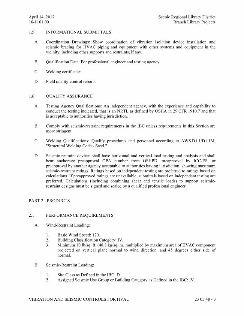
April 14, 2017 Scenic Regional Library District
16-1161.00 Branch Library Projects
VIBRATION AND SEISMIC CONTROLS FOR HVAC 23 05 48 - 3
1.5 INFORMATIONAL SUBMITTALS
A. Coordination Drawings: Show coordination of vibration isolation device installation and
seismic bracing for HVAC piping and equipment with other systems and equipment in the
vicinity, including other supports and restraints, if any.
B. Qualification Data: For professional engineer and testing agency.
C. Welding certificates.
D. Field quality-control reports.
1.6 QUALITY ASSURANCE
A. Testing Agency Qualifications: An independent agency, with the experience and capability to
conduct the testing indicated, that is an NRTL as defined by OSHA in 29 CFR 1910.7 and that
is acceptable to authorities having jurisdiction.
B. Comply with seismic-restraint requirements in the IBC unless requirements in this Section are
more stringent.
C. Welding Qualifications: Qualify procedures and personnel according to AWS D1.1/D1.1M,
"Structural Welding Code - Steel."
D. Seismic-restraint devices shall have horizontal and vertical load testing and analysis and shall
bear anchorage preapproval OPA number from OSHPD, preapproval by ICC-ES, or
preapproval by another agency acceptable to authorities having jurisdiction, showing maximum
seismic-restraint ratings. Ratings based on independent testing are preferred to ratings based on
calculations. If preapproved ratings are unavailable, submittals based on independent testing are
preferred. Calculations (including combining shear and tensile loads) to support seismic-
restraint designs must be signed and sealed by a qualified professional engineer.
PART 2 - PRODUCTS
2.1 PERFORMANCE REQUIREMENTS
A. Wind-Restraint Loading:
1. Basic Wind Speed: 120.
2. Building Classification Category: IV.
3. Minimum 10 lb/sq. ft. (48.8 kg/sq. m) multiplied by maximum area of HVAC component
projected on vertical plane normal to wind direction, and 45 degrees either side of
normal.
B. Seismic-Restraint Loading:
1. Site Class as Defined in the IBC: D.
2. Assigned Seismic Use Group or Building Category as Defined in the IBC: IV.
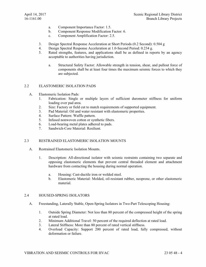
April 14, 2017 Scenic Regional Library District
16-1161.00 Branch Library Projects
VIBRATION AND SEISMIC CONTROLS FOR HVAC 23 05 48 - 4
a. Component Importance Factor: 1.5.
b. Component Response Modification Factor: 6.
c. Component Amplification Factor: 2.5.
3. Design Spectral Response Acceleration at Short Periods (0.2 Second): 0.504 g
4. Design Spectral Response Acceleration at 1.0-Second Period: 0.234 g.
5. Rated strengths, features, and applications shall be as defined in reports by an agency
acceptable to authorities having jurisdiction.
a. Structural Safety Factor: Allowable strength in tension, shear, and pullout force of
components shall be at least four times the maximum seismic forces to which they
are subjected.
2.2 ELASTOMERIC ISOLATION PADS
A. Elastomeric Isolation Pads:
1. Fabrication: Single or multiple layers of sufficient durometer stiffness for uniform
loading over pad area.
2. Size: Factory or field cut to match requirements of supported equipment.
3. Pad Material: Oil and water resistant with elastomeric properties.
4. Surface Pattern: Waffle pattern.
5. Infused nonwoven cotton or synthetic fibers.
6. Load-bearing metal plates adhered to pads.
7. Sandwich-Core Material: Resilient.
2.3 RESTRAINED ELASTOMERIC ISOLATION MOUNTS
A. Restrained Elastomeric Isolation Mounts.
1. Description: All-directional isolator with seismic restraints containing two separate and
opposing elastomeric elements that prevent central threaded element and attachment
hardware from contacting the housing during normal operation.
a. Housing: Cast-ductile iron or welded steel.
b. Elastomeric Material: Molded, oil-resistant rubber, neoprene, or other elastomeric
material.
2.4 HOUSED-SPRING ISOLATORS
A. Freestanding, Laterally Stable, Open-Spring Isolators in Two-Part Telescoping Housing:
1. Outside Spring Diameter: Not less than 80 percent of the compressed height of the spring
at rated load.
2. Minimum Additional Travel: 50 percent of the required deflection at rated load.
3. Lateral Stiffness: More than 80 percent of rated vertical stiffness.
4. Overload Capacity: Support 200 percent of rated load, fully compressed, without
deformation or failure.
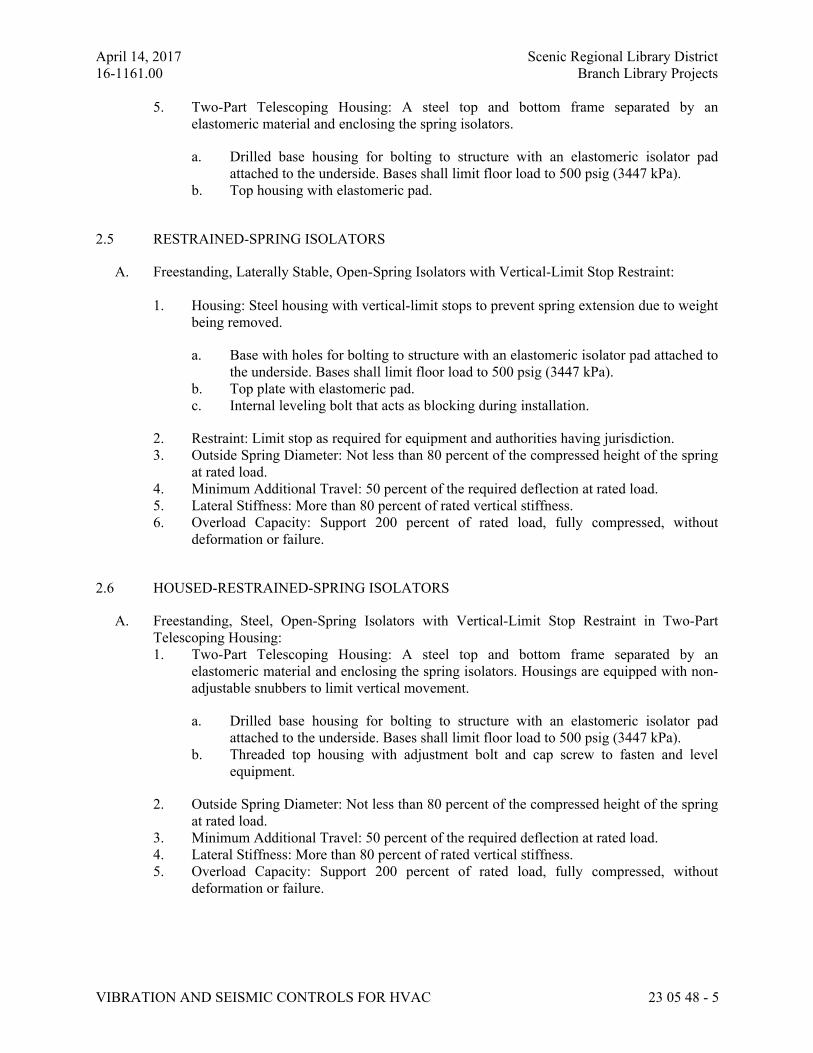
April 14, 2017 Scenic Regional Library District
16-1161.00 Branch Library Projects
VIBRATION AND SEISMIC CONTROLS FOR HVAC 23 05 48 - 5
5. Two-Part Telescoping Housing: A steel top and bottom frame separated by an
elastomeric material and enclosing the spring isolators.
a. Drilled base housing for bolting to structure with an elastomeric isolator pad
attached to the underside. Bases shall limit floor load to 500 psig (3447 kPa).
b. Top housing with elastomeric pad.
2.5 RESTRAINED-SPRING ISOLATORS
A. Freestanding, Laterally Stable, Open-Spring Isolators with Vertical-Limit Stop Restraint:
1. Housing: Steel housing with vertical-limit stops to prevent spring extension due to weight
being removed.
a. Base with holes for bolting to structure with an elastomeric isolator pad attached to
the underside. Bases shall limit floor load to 500 psig (3447 kPa).
b. Top plate with elastomeric pad.
c. Internal leveling bolt that acts as blocking during installation.
2. Restraint: Limit stop as required for equipment and authorities having jurisdiction.
3. Outside Spring Diameter: Not less than 80 percent of the compressed height of the spring
at rated load.
4. Minimum Additional Travel: 50 percent of the required deflection at rated load.
5. Lateral Stiffness: More than 80 percent of rated vertical stiffness.
6. Overload Capacity: Support 200 percent of rated load, fully compressed, without
deformation or failure.
2.6 HOUSED-RESTRAINED-SPRING ISOLATORS
A. Freestanding, Steel, Open-Spring Isolators with Vertical-Limit Stop Restraint in Two-Part
Telescoping Housing:
1. Two-Part Telescoping Housing: A steel top and bottom frame separated by an
elastomeric material and enclosing the spring isolators. Housings are equipped with non-
adjustable snubbers to limit vertical movement.
a. Drilled base housing for bolting to structure with an elastomeric isolator pad
attached to the underside. Bases shall limit floor load to 500 psig (3447 kPa).
b. Threaded top housing with adjustment bolt and cap screw to fasten and level
equipment.
2. Outside Spring Diameter: Not less than 80 percent of the compressed height of the spring
at rated load.
3. Minimum Additional Travel: 50 percent of the required deflection at rated load.
4. Lateral Stiffness: More than 80 percent of rated vertical stiffness.
5. Overload Capacity: Support 200 percent of rated load, fully compressed, without
deformation or failure.
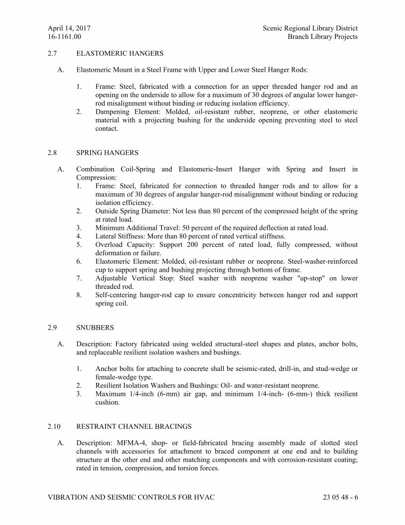
April 14, 2017 Scenic Regional Library District
16-1161.00 Branch Library Projects
VIBRATION AND SEISMIC CONTROLS FOR HVAC 23 05 48 - 6
2.7 ELASTOMERIC HANGERS
A. Elastomeric Mount in a Steel Frame with Upper and Lower Steel Hanger Rods:
1. Frame: Steel, fabricated with a connection for an upper threaded hanger rod and an
opening on the underside to allow for a maximum of 30 degrees of angular lower hanger-
rod misalignment without binding or reducing isolation efficiency.
2. Dampening Element: Molded, oil-resistant rubber, neoprene, or other elastomeric
material with a projecting bushing for the underside opening preventing steel to steel
contact.
2.8 SPRING HANGERS
A. Combination Coil-Spring and Elastomeric-Insert Hanger with Spring and Insert in
Compression:
1. Frame: Steel, fabricated for connection to threaded hanger rods and to allow for a
maximum of 30 degrees of angular hanger-rod misalignment without binding or reducing
isolation efficiency.
2. Outside Spring Diameter: Not less than 80 percent of the compressed height of the spring
at rated load.
3. Minimum Additional Travel: 50 percent of the required deflection at rated load.
4. Lateral Stiffness: More than 80 percent of rated vertical stiffness.
5. Overload Capacity: Support 200 percent of rated load, fully compressed, without
deformation or failure.
6. Elastomeric Element: Molded, oil-resistant rubber or neoprene. Steel-washer-reinforced
cup to support spring and bushing projecting through bottom of frame.
7. Adjustable Vertical Stop: Steel washer with neoprene washer "up-stop" on lower
threaded rod.
8. Self-centering hanger-rod cap to ensure concentricity between hanger rod and support
spring coil.
2.9 SNUBBERS
A. Description: Factory fabricated using welded structural-steel shapes and plates, anchor bolts,
and replaceable resilient isolation washers and bushings.
1. Anchor bolts for attaching to concrete shall be seismic-rated, drill-in, and stud-wedge or
female-wedge type.
2. Resilient Isolation Washers and Bushings: Oil- and water-resistant neoprene.
3. Maximum 1/4-inch (6-mm) air gap, and minimum 1/4-inch- (6-mm-) thick resilient
cushion.
2.10 RESTRAINT CHANNEL BRACINGS
A. Description: MFMA-4, shop- or field-fabricated bracing assembly made of slotted steel
channels with accessories for attachment to braced component at one end and to building
structure at the other end and other matching components and with corrosion-resistant coating;
rated in tension, compression, and torsion forces.
April 14, 2017 Scenic Regional Library District
16-1161.00 Branch Library Projects
VIBRATION AND SEISMIC CONTROLS FOR HVAC 23 05 48 - 7
2.11 RESTRAINT CABLES
A. Restraint Cables: ASTM A 492 stainless-steel cables. End connections made of steel assemblies
with thimbles, brackets, swivel, and bolts designed for restraining cable service; with a
minimum of two clamping bolts for cable engagement.
2.12 SEISMIC-RESTRAINT ACCESSORIES
A. Hanger-Rod Stiffener: Steel tube or steel slotted-support-system sleeve with internally bolted
connections to hanger rod.
B. Hinged and Swivel Brace Attachments: Multifunctional steel connectors for attaching hangers
to rigid channel bracings and restraint cables.
C. Bushings for Floor-Mounted Equipment Anchor Bolts: Neoprene bushings designed for rigid
equipment mountings, and matched to type and size of anchor bolts and studs.
D. Bushing Assemblies for Wall-Mounted Equipment Anchorage: Assemblies of neoprene
elements and steel sleeves designed for rigid equipment mountings, and matched to type and
size of attachment devices used.
E. Resilient Isolation Washers and Bushings: One-piece, molded, oil- and water-resistant
neoprene, with a flat washer face.
PART 3 - EXECUTION
3.1 EXAMINATION
A. Examine areas and equipment to receive vibration isolation and seismic- and wind-control
devices for compliance with requirements for installation tolerances and other conditions
affecting performance of the Work.
B. Examine roughing-in of reinforcement and cast-in-place anchors to verify actual locations
before installation.
C. Proceed with installation only after unsatisfactory conditions have been corrected.
3.2 APPLICATIONS
A. Multiple Pipe Supports: Secure pipes to trapeze member with clamps approved for application
by an agency acceptable to authorities having jurisdiction.
B. Hanger-Rod Stiffeners: Install hanger-rod stiffeners where indicated or scheduled on Drawings
to receive them and where required to prevent buckling of hanger rods due to seismic forces.
C. Strength of Support and Seismic-Restraint Assemblies: Where not indicated, select sizes of
components so strength is adequate to carry present and future static and seismic loads within
specified loading limits.
April 14, 2017 Scenic Regional Library District
16-1161.00 Branch Library Projects
VIBRATION AND SEISMIC CONTROLS FOR HVAC 23 05 48 - 8
3.3 VIBRATION CONTROL AND SEISMIC-RESTRAINT DEVICE INSTALLATION
A. Coordinate the location of embedded connection hardware with supported equipment
attachment and mounting points and with requirements for concrete reinforcement and
formwork specified in Section 033000 "Cast-in-Place Concrete."
B. Installation of vibration isolators must not cause any change of position of equipment, piping, or
ductwork resulting in stresses or misalignment.
C. Comply with requirements in Section 077200 "Roof Accessories" for installation of roof curbs,
equipment supports, and roof penetrations.
D. Equipment Restraints:
1. Install seismic snubbers on HVAC equipment mounted on vibration isolators. Locate
snubbers as close as possible to vibration isolators and bolt to equipment base and
supporting structure.
2. Install resilient bolt isolation washers on equipment anchor bolts where clearance
between anchor and adjacent surface exceeds 0.125 inch (3.2 mm).
3. Install seismic-restraint devices using methods approved by an agency acceptable to
authorities having jurisdiction that provides required submittals for component.
E. Piping Restraints:
1. Comply with requirements in MSS SP-127.
2. Space lateral supports a maximum of 40 feet o.c., and longitudinal supports a maximum
of 80 feet o.c.
3. Brace a change of direction longer than 12 feet (3.7 m).
F. Install cables so they do not bend across edges of adjacent equipment or building structure.
G. Install seismic-restraint devices using methods approved by an agency acceptable to authorities
having jurisdiction that provides required submittals for component.
H. Install bushing assemblies for anchor bolts for floor-mounted equipment, arranged to provide
resilient media between anchor bolt and mounting hole in concrete base.
I. Install bushing assemblies for mounting bolts for wall-mounted equipment, arranged to provide
resilient media where equipment or equipment-mounting channels are attached to wall.
J. Attachment to Structure: If specific attachment is not indicated, anchor bracing to structure at
flanges of beams, at upper truss chords of bar joists, or at concrete members.
K. Drilled-in Anchors:
1. Identify position of reinforcing steel and other embedded items prior to drilling holes for
anchors. Do not damage existing reinforcing or embedded items during coring or drilling.
Notify the structural engineer if reinforcing steel or other embedded items are
encountered during drilling. Locate and avoid prestressed tendons, electrical and
telecommunications conduit, and gas lines.
April 14, 2017 Scenic Regional Library District
16-1161.00 Branch Library Projects
VIBRATION AND SEISMIC CONTROLS FOR HVAC 23 05 48 - 9
2. Do not drill holes in concrete or masonry until concrete, mortar, or grout has achieved
full design strength.
3. Wedge Anchors: Protect threads from damage during anchor installation. Heavy-duty
sleeve anchors shall be installed with sleeve fully engaged in the structural element to
which anchor is to be fastened.
4. Adhesive Anchors: Clean holes to remove loose material and drilling dust prior to
installation of adhesive. Place adhesive in holes proceeding from the bottom of the hole
and progressing toward the surface in such a manner as to avoid introduction of air
pockets in the adhesive.
5. Set anchors to manufacturer's recommended torque, using a torque wrench.
6. Install zinc-coated steel anchors for interior and stainless-steel anchors for exterior
applications.
3.4 ACCOMMODATION OF DIFFERENTIAL SEISMIC MOTION
A. Install flexible connections in piping where they cross seismic joints, where adjacent sections or
branches are supported by different structural elements, and where the connections terminate
with connection to equipment that is anchored to a different structural element from the one
supporting the connections as they approach equipment.
3.5 FIELD QUALITY CONTROL
A. Testing Agency: Engage a qualified testing agency to perform tests and inspections.
B. Perform tests and inspections.
C. Tests and Inspections:
1. Provide evidence of recent calibration of test equipment by a testing agency acceptable to
authorities having jurisdiction.
2. Schedule test with Owner, through Architect, before connecting anchorage device to
restrained component (unless postconnection testing has been approved), and with at least
seven days' advance notice.
3. Obtain Architect's approval before transmitting test loads to structure. Provide temporary
load-spreading members.
4. Test at least four of each type and size of installed anchors and fasteners selected by
Architect.
5. Test to 90 percent of rated proof load of device.
6. Measure isolator restraint clearance.
7. Measure isolator deflection.
8. Verify snubber minimum clearances.
D. Remove and replace malfunctioning units and retest as specified above.
E. Prepare test and inspection reports.
April 14, 2017 Scenic Regional Library District
16-1161.00 Branch Library Projects
VIBRATION AND SEISMIC CONTROLS FOR HVAC 23 05 48 - 10
3.6 ADJUSTING
A. Adjust isolators after piping system is at operating weight.
B. Adjust limit stops on restrained-spring isolators to mount equipment at normal operating height.
After equipment installation is complete, adjust limit stops so they are out of contact during
normal operation.
END OF SECTION 23 05 48
April 14, 2017 Scenic Regional Library District
16-1161.00 Branch Library Projects
IDENTIFICATION FOR HVAC PIPING AND EQUIPMENT 230553 - 1
SECTION 230553 - IDENTIFICATION FOR HVAC PIPING AND EQUIPMENT
ALL LIBRARIES
PART 1 - GENERAL
1.1 RELATED DOCUMENTS
A. Drawings and general provisions of the Contract, including General and Supplementary
Conditions and Division 01 Specification Sections, apply to this Section.
1.2 SUMMARY
A. Section Includes:
1. Equipment labels.
2. Warning signs and labels.
3. Pipe labels.
4. Duct labels.
5. Stencils.
1.3 ACTION SUBMITTALS
A. Product Data: For each type of product indicated.
B. Samples: For color, letter style, and graphic representation required for each identification
material and device.
C. Equipment Label Schedule: Include a listing of all equipment to be labeled with the proposed
content for each label.
D. Valve numbering scheme.
E. Valve Schedules: For each piping system to include in maintenance manuals.
1.4 COORDINATION
A. Coordinate installation of identifying devices with completion of covering and painting of
surfaces where devices are to be applied.
B. Coordinate installation of identifying devices with locations of access panels and doors.
C. Install identifying devices before installing acoustical ceilings and similar concealment.
Comment [DL1]: Edit this out if you
don’t want to see samples. 12-4-14
April 14, 2017 Scenic Regional Library District
16-1161.00 Branch Library Projects
IDENTIFICATION FOR HVAC PIPING AND EQUIPMENT 230553 - 2
PART 2 - PRODUCTS
2.1 EQUIPMENT LABELS
A. Metal Labels for Equipment:
1. Material and Thickness: Stainless steel, 0.025-inch, minimum thickness, and having
predrilled or stamped holes for attachment hardware.
2. Minimum Label Size: Length and width vary for required label content, but not less than
2-1/2 by 3/4 inch.
3. Minimum Letter Size: 1/4 inch for name of units if viewing distance is less than 24
inches, 1/2 inch for viewing distances up to 72 inches, and proportionately larger lettering
for greater viewing distances. Include secondary lettering two-thirds to three-fourths the
size of principal lettering.
4. Fasteners: Stainless-steel rivets or self-tapping screws.
5. Adhesive: Contact-type permanent adhesive, compatible with label and with substrate.
B. Plastic Labels for Equipment:
1. Material and Thickness: Multilayer, multicolor, plastic labels for mechanical engraving,
1/16 inch thick, and having predrilled holes for attachment hardware.
2. Letter Color: Black.
3. Background Color: White.
4. Maximum Temperature: Able to withstand temperatures up to 160 deg F.
5. Minimum Label Size: Length and width vary for required label content, but not less than
2-1/2 by 3/4 inch.
6. Minimum Letter Size: 1/4 inch for name of units if viewing distance is less than 24
inches, 1/2 inch for viewing distances up to 72 inches, and proportionately larger lettering
for greater viewing distances. Include secondary lettering two-thirds to three-fourths the
size of principal lettering.
7. Fasteners: Stainless-steel rivets or self-tapping screws.
8. Adhesive: Contact-type permanent adhesive, compatible with label and with substrate.
C. Label Content: Include equipment's Drawing designation or unique equipment number,
Drawing numbers where equipment is indicated (plans, details, and schedules), plus the
Specification Section number and title where equipment is specified.
D. Equipment Label Schedule: For each item of equipment to be labeled, on 8-1/2-by-11-inch
bond paper. Tabulate equipment identification number and identify Drawing numbers where
equipment is indicated (plans, details, and schedules), plus the Specification Section number
and title where equipment is specified. Equipment schedule shall be included in operation and
maintenance data.
2.2 WARNING SIGNS AND LABELS
A. Material and Thickness: Multilayer, multicolor, plastic labels for mechanical engraving, 1/16
inch thick, and having predrilled holes for attachment hardware.
B. Letter Color: Red.
Comment [DL2]: If working in a bigger
facility, ask if they have a standard
naming/tagging scheme for devices and
edit specs accordingly. 12-4-14
Comment [DL3]: 1/16” is standard
Comment [DL4]: Black, Green, Red and
blue with white letters, Yellow and White
with Black letters.
Comment [DL5]: 1/16 is standard 12-4-
2014
April 14, 2017 Scenic Regional Library District
16-1161.00 Branch Library Projects
IDENTIFICATION FOR HVAC PIPING AND EQUIPMENT 230553 - 3
C. Background Color: White.
D. Maximum Temperature: Able to withstand temperatures up to 160 deg F.
E. Minimum Label Size: Length and width vary for required label content, but not less than 2-1/2
by 3/4 inch.
F. Minimum Letter Size: 1/4 inch for name of units if viewing distance is less than 24 inches, 1/2
inch for viewing distances up to 72 inches, and proportionately larger lettering for greater
viewing distances. Include secondary lettering two-thirds to three-fourths the size of principal
lettering.
G. Fasteners: Stainless-steel rivets or self-tapping screws.
H. Adhesive: Contact-type permanent adhesive, compatible with label and with substrate.
I. Label Content: Include caution and warning information, plus emergency notification
instructions.
2.3 PIPE LABELS
A. General Requirements for Manufactured Pipe Labels: Preprinted, color-coded, with lettering
indicating service, and showing flow direction.
B. Pretensioned Pipe Labels: Precoiled, semirigid plastic formed to cover full circumference of
pipe and to attach to pipe without fasteners or adhesive.
C. Self-Adhesive Pipe Labels: Printed plastic with contact-type, permanent-adhesive backing.
D. Pipe Label Contents: Include identification of piping service using same designations or
abbreviations as used on Drawings, pipe size, and an arrow indicating flow direction.
1. Flow-Direction Arrows: Integral with piping system service lettering to accommodate
both directions, or as separate unit on each pipe label to indicate flow direction.
2. Lettering Size: At least 1-1/2 inches high.
2.4 DUCT LABELS
A. Material and Thickness: Multilayer, multicolor, plastic labels for mechanical engraving, 1/16
inch thick, and having predrilled holes for attachment hardware.
B. Letter Color: Black.
C. Background Color: White.
D. Maximum Temperature: Able to withstand temperatures up to 160 deg F.
E. Minimum Label Size: Length and width vary for required label content, but not less than 2-1/2
by 3/4 inch.
Comment [DL6]: Black, Green, Red and
blue with white letters, Yellow and White
with Black letters.
Make sure it’s different then a normal
sign.
12-4-2014
Comment [DL7]: Black, Green, Red and
blue with white letters, Yellow and White
with Black letters.
April 14, 2017 Scenic Regional Library District
16-1161.00 Branch Library Projects
IDENTIFICATION FOR HVAC PIPING AND EQUIPMENT 230553 - 4
F. Minimum Letter Size: 1/4 inch for name of units if viewing distance is less than 24 inches, 1/2
inch for viewing distances up to 72 inches, and proportionately larger lettering for greater
viewing distances. Include secondary lettering two-thirds to three-fourths the size of principal
lettering.
G. Fasteners: Stainless-steel rivets or self-tapping screws.
H. Adhesive: Contact-type permanent adhesive, compatible with label and with substrate.
I. Duct Label Contents: Include identification of duct service using same designations or
abbreviations as used on Drawings, duct size, and an arrow indicating flow direction.
1. Flow-Direction Arrows: Integral with duct system service lettering to accommodate both
directions, or as separate unit on each duct label to indicate flow direction.
2. Lettering Size: At least 1-1/2 inches high.
2.5 STENCILS
A. Stencils: Prepared with letter sizes according to ASME A13.1 for piping; minimum letter
height of 1-1/4 inches for ducts; and minimum letter height of 3/4 inch for access panel and
door labels, equipment labels, and similar operational instructions.
1. Stencil Paint: Exterior, gloss, alkyd enamel black unless otherwise indicated. Paint may
be in pressurized spray-can form.
2. Identification Paint: Exterior, alkyd enamel in colors according to ASME A13.1 unless
otherwise indicated.
PART 3 - EXECUTION
3.1 PREPARATION
A. Clean piping and equipment surfaces of substances that could impair bond of identification
devices, including dirt, oil, grease, release agents, and incompatible primers, paints, and
encapsulants.
3.2 EQUIPMENT LABEL INSTALLATION
A. Install or permanently fasten labels on each major item of mechanical equipment.
B. Locate equipment labels where accessible and visible.
3.3 PIPE LABEL INSTALLATION
A. Piping Color-Coding: Painting of piping is specified in [Section 099123 "Interior Painting".
Comment [DL8]: Water based
April 14, 2017 Scenic Regional Library District
16-1161.00 Branch Library Projects
IDENTIFICATION FOR HVAC PIPING AND EQUIPMENT 230553 - 5
B. Stenciled Pipe Label Option: Stenciled labels may be provided instead of manufactured pipe
labels, at Installer's option. Install stenciled pipe labels with painted, color-coded bands or
rectangles, complying with ASME A13.1, on each piping system.
1. Identification Paint: Use for contrasting background.
2. Stencil Paint: Use for pipe marking.
C. Locate pipe labels where piping is exposed or above accessible ceilings in finished spaces;
machine rooms; accessible maintenance spaces such as shafts, tunnels, and plenums; and
exterior exposed locations as follows:
1. Near each valve and control device.
2. Near each branch connection, excluding short takeoffs for fixtures and terminal units.
Where flow pattern is not obvious, mark each pipe at branch.
3. Near penetrations through walls, floors, ceilings, and inaccessible enclosures.
4. At access doors, manholes, and similar access points that permit view of concealed
piping.
5. Near major equipment items and other points of origination and termination.
6. Spaced at maximum intervals of 50 feet along each run. Reduce intervals to 25 feet in
areas of congested piping and equipment.
7. On piping above removable acoustical ceilings. Omit intermediately spaced labels.
D. Pipe Label Color Schedule:
1. Refrigerant Piping:
a. Background Color: White.
b. Letter Color: Black.
3.4 DUCT LABEL INSTALLATION
A. Install self-adhesive duct labels with permanent adhesive on air ducts in the following color
codes:
1. Blue: For cold-air supply ducts.
2. Yellow: For hot-air supply ducts.
3. Green: For exhaust-, outside-, relief-, return-, and mixed-air ducts.
4. ASME A13.1 Colors and Designs: For hazardous material exhaust.
B. Stenciled Duct Label Option: Stenciled labels, showing service and flow direction, may be
provided instead of plastic-laminated duct labels, at Installer's option, if lettering larger than 1
inch high is needed for proper identification because of distance from normal location of
required identification.
C. Locate labels near points where ducts enter into concealed spaces and at maximum intervals of
50 feet in each space where ducts are exposed or concealed by removable ceiling system.
END OF SECTION 230553
April 14, 2017 Scenic Regional Library District
16-1161.00 Branch Library Projects
TESTING, ADJUSTING, AND BALANCING FOR HVAC 230593 - 1
SECTION 230593 - TESTING, ADJUSTING, AND BALANCING FOR HVAC
ALL LIBRARIES
PART 1 - GENERAL
1.1 RELATED DOCUMENTS
A. Drawings and general provisions of the Contract, including General and Supplementary
Conditions and Division 01 Specification Sections, apply to this Section.
1.2 SUMMARY
A. Section Includes:
1. Balancing Air Systems:
a. Constant-volume air systems.
b. Variable-air-volume systems.
1.3 DEFINITIONS
A. AABC: Associated Air Balance Council.
B. NEBB: National Environmental Balancing Bureau.
C. TAB: Testing, adjusting, and balancing.
D. TABB: Testing, Adjusting, and Balancing Bureau.
E. TAB Specialist: An entity engaged to perform TAB Work.
1.4 INFORMATIONAL SUBMITTALS
A. Qualification Data: Within 30 days of Contractor's Notice to Proceed, submit documentation
that the TAB contractor and this Project's TAB team members meet the qualifications specified
in "Quality Assurance" Article.
B. Contract Documents Examination Report: Within 30 days of Contractor's Notice to Proceed,
submit the Contract Documents review report as specified in Part 3.
C. Strategies and Procedures Plan: Within 30 days of Contractor's Notice to Proceed, submit TAB
strategies and step-by-step procedures as specified in "Preparation" Article.
D. Certified TAB reports.
Comment [DEL1]: This is a long
section. We should consider creating a
separate section for small projects with
limited T&B requirements. 10-30-14
Comment [DEL2]: AABC members are
independent of contractors. 10-30-14
Comment [DEL3]: NEBB firms can also
be contractors. There is a potential here
for a conflict of interest. 10-30-14
Comment [DEL4]: TABB firms can also
be conractors. There is a potential here for
a conflict of interest. 10-30-14
April 14, 2017 Scenic Regional Library District
16-1161.00 Branch Library Projects
TESTING, ADJUSTING, AND BALANCING FOR HVAC 230593 - 2
E. Sample report forms.
F. Instrument calibration reports, to include the following:
1. Instrument type and make.
2. Serial number.
3. Application.
4. Dates of use.
5. Dates of calibration.
1.5 QUALITY ASSURANCE
A. TAB Contractor Qualifications: Engage a TAB entity certified by AABC or TABB.
1. TAB Field Supervisor: Employee of the TAB contractor and certified by AABC or
TABB.
2. TAB Technician: Employee of the TAB contractor and who is certified by AABC or
TABB as a TAB technician.
a. Coordination of documentation and communication flow.
B. Certify TAB field data reports and perform the following:
1. Review field data reports to validate accuracy of data and to prepare certified TAB
reports.
2. Certify that the TAB team complied with the approved TAB plan and the procedures
specified and referenced in this Specification.
C. TAB Report Forms: Use standard TAB contractor's forms approved by Architect.
D. Instrumentation Type, Quantity, Accuracy, and Calibration: As described in ASHRAE 111,
Section 5, "Instrumentation."
E. ASHRAE Compliance: Applicable requirements in ASHRAE 62.1, Section 7.2.2 - "Air
Balancing."
F. ASHRAE/IESNA Compliance: Applicable requirements in ASHRAE/IESNA 90.1,
Section 6.7.2.3 - "System Balancing."
1.6 PROJECT CONDITIONS
A. Full Owner Occupancy: Owner will occupy the site and existing building during entire TAB
period. Cooperate with Owner during TAB operations to minimize conflicts with Owner's
operations.
B. Partial Owner Occupancy: Owner may occupy completed areas of building before Substantial
Completion. Cooperate with Owner during TAB operations to minimize conflicts with Owner's
operations.
Comment [DEL5]: If you want to leave
all three certifications, this is where you
could add a statement that the T&B
contractor shall be indepenedent of the
mechanical contractor. Possibly work
with the architect to determine if the T&B
contractor’s contract can be held by the
GC, not the MC. 10-30-14
April 14, 2017 Scenic Regional Library District
16-1161.00 Branch Library Projects
TESTING, ADJUSTING, AND BALANCING FOR HVAC 230593 - 3
1.7 COORDINATION
A. Notice: Provide seven days' advance notice for each test. Include scheduled test dates and
times.
B. Perform TAB after leakage and pressure tests on air distribution systems have been
satisfactorily completed.
PART 2 - PRODUCTS (Not Applicable)
PART 3 - EXECUTION
3.1 EXAMINATION
A. Examine the Contract Documents to become familiar with Project requirements and to discover
conditions in systems' designs that may preclude proper TAB of systems and equipment.
B. Examine systems for installed balancing devices, such as test ports, gage cocks, thermometer
wells, flow-control devices, balancing valves and fittings, and manual volume dampers. Verify
that locations of these balancing devices are accessible.
C. Examine the approved submittals for HVAC systems and equipment.
D. Examine design data including HVAC system descriptions, statements of design assumptions
for environmental conditions and systems' output, and statements of philosophies and
assumptions about HVAC system and equipment controls.
E. Examine ceiling plenums and underfloor air plenums used for supply, return, or relief air to
verify that they meet the leakage class of connected ducts as specified in Section 233113 "Metal
Ducts" and are properly separated from adjacent areas. Verify that penetrations in plenum walls
are sealed and fire-stopped if required.
F. Examine equipment performance data including fan and pump curves.
1. Relate performance data to Project conditions and requirements, including system effects
that can create undesired or unpredicted conditions that cause reduced capacities in all or
part of a system.
2. Calculate system-effect factors to reduce performance ratings of HVAC equipment when
installed under conditions different from the conditions used to rate equipment
performance. To calculate system effects for air systems, use tables and charts found in
AMCA 201, "Fans and Systems," or in SMACNA's "HVAC Systems - Duct Design."
Compare results with the design data and installed conditions.
G. Examine system and equipment installations and verify that field quality-control testing,
cleaning, and adjusting specified in individual Sections have been performed.
H. Examine test reports specified in individual system and equipment Sections.
Comment [DEL6]: I don’t know that any
of the return air ceiling plenums we’ve
worked with would specifically meet a
duct leakage class. 10-30-14
April 14, 2017 Scenic Regional Library District
16-1161.00 Branch Library Projects
TESTING, ADJUSTING, AND BALANCING FOR HVAC 230593 - 4
I. Examine HVAC equipment and filters and verify that bearings are greased, belts are aligned
and tight, and equipment with functioning controls is ready for operation.
J. Examine terminal units, such as variable-air-volume boxes, and verify that they are accessible
and their controls are connected and functioning.
K. Examine strainers. Verify that startup screens are replaced by permanent screens with indicated
perforations.
L. Examine three-way valves for proper installation for their intended function of diverting or
mixing fluid flows.
M. Examine heat-transfer coils for correct piping connections and for clean and straight fins.
N. Examine system pumps to ensure absence of entrained air in the suction piping.
O. Examine operating safety interlocks and controls on HVAC equipment.
P. Report deficiencies discovered before and during performance of TAB procedures. Observe
and record system reactions to changes in conditions. Record default set points if different from
indicated values.
3.2 PREPARATION
A. Prepare a TAB plan that includes strategies and step-by-step procedures.
B. Complete system-readiness checks and prepare reports. Verify the following:
1. Permanent electrical-power wiring is complete.
2. Hydronic systems are filled, clean, and free of air.
3. Automatic temperature-control systems are operational.
4. Equipment and duct access doors are securely closed.
5. Balance, smoke, and fire dampers are open.
6. Isolating and balancing valves are open and control valves are operational.
7. Ceilings are installed in critical areas where air-pattern adjustments are required and
access to balancing devices is provided.
8. Windows and doors can be closed so indicated conditions for system operations can be
met.
3.3 GENERAL PROCEDURES FOR TESTING AND BALANCING
A. Perform testing and balancing procedures on each system according to the procedures contained
in ASHRAE 111 AND SMACNA's "HVAC Systems - Testing, Adjusting, and Balancing" and
in this Section.
1. Comply with requirements in ASHRAE 62.1, Section 7.2.2 - "Air Balancing."
B. Cut insulation, ducts, pipes, and equipment cabinets for installation of test probes to the
minimum extent necessary for TAB procedures.
April 14, 2017 Scenic Regional Library District
16-1161.00 Branch Library Projects
TESTING, ADJUSTING, AND BALANCING FOR HVAC 230593 - 5
1. After testing and balancing, patch probe holes in ducts with same material and thickness
as used to construct ducts.
2. After testing and balancing, install test ports and duct access doors that comply with
requirements in Section 233300 "Air Duct Accessories."
3. Install and join new insulation that matches removed materials. Restore insulation,
coverings, vapor barrier, and finish according to Section 230713 "Duct Insulation,"
Section 230716 "HVAC Equipment Insulation," and Section 230719 "HVAC Piping
Insulation."
C. Mark equipment and balancing devices, including damper-control positions, valve position
indicators, fan-speed-control levers, and similar controls and devices, with paint or other
suitable, permanent identification material to show final settings.
D. Take and report testing and balancing measurements in [inch-pound (IP)] [and] [metric (SI)]
units.
3.4 GENERAL PROCEDURES FOR BALANCING AIR SYSTEMS
A. Prepare test reports for both fans and outlets. Obtain manufacturer's outlet factors and
recommended testing procedures. Crosscheck the summation of required outlet volumes with
required fan volumes.
B. Prepare schematic diagrams of systems' "as-built" duct layouts.
C. For variable-air-volume systems, develop a plan to simulate diversity.
D. Determine the best locations in main and branch ducts for accurate duct-airflow measurements.
E. Check airflow patterns from the outdoor-air louvers and dampers and the return- and exhaust-air
dampers through the supply-fan discharge and mixing dampers.
F. Locate start-stop and disconnect switches, electrical interlocks, and motor starters.
G. Verify that motor starters are equipped with properly sized thermal protection.
H. Check dampers for proper position to achieve desired airflow path.
I. Check for airflow blockages.
J. Check condensate drains for proper connections and functioning.
K. Check for proper sealing of air-handling-unit components.
L. Verify that air duct system is sealed as specified in Section 233113 "Metal Ducts."
3.5 PROCEDURES FOR CONSTANT-VOLUME AIR SYSTEMS
A. Adjust fans to deliver total indicated airflows within the maximum allowable fan speed listed by
fan manufacturer.
April 14, 2017 Scenic Regional Library District
16-1161.00 Branch Library Projects
TESTING, ADJUSTING, AND BALANCING FOR HVAC 230593 - 6
1. Measure total airflow.
a. Where sufficient space in ducts is unavailable for Pitot-tube traverse
measurements, measure airflow at terminal outlets and inlets and calculate the total
airflow.
2. Measure fan static pressures as follows to determine actual static pressure:
a. Measure outlet static pressure as far downstream from the fan as practical and
upstream from restrictions in ducts such as elbows and transitions.
b. Measure static pressure directly at the fan outlet or through the flexible connection.
c. Measure inlet static pressure of single-inlet fans in the inlet duct as near the fan as
possible, upstream from the flexible connection, and downstream from duct
restrictions.
d. Measure inlet static pressure of double-inlet fans through the wall of the plenum
that houses the fan.
3. Measure static pressure across each component that makes up an air-handling unit,
rooftop unit, and other air-handling and -treating equipment.
a. Report the cleanliness status of filters and the time static pressures are measured.
4. Measure static pressures entering and leaving other devices, such as sound traps, heat-
recovery equipment, and air washers, under final balanced conditions.
5. Review Record Documents to determine variations in design static pressures versus
actual static pressures. Calculate actual system-effect factors. Recommend adjustments
to accommodate actual conditions.
6. Obtain approval from Architect for adjustment of fan speed higher or lower than
indicated speed. Comply with requirements in HVAC Sections for air-handling units for
adjustment of fans, belts, and pulley sizes to achieve indicated air-handling-unit
performance.
7. Do not make fan-speed adjustments that result in motor overload. Consult equipment
manufacturers about fan-speed safety factors. Modulate dampers and measure fan-motor
amperage to ensure that no overload will occur. Measure amperage in full-cooling, full-
heating, economizer, and any other operating mode to determine the maximum required
brake horsepower.
B. Adjust volume dampers for main duct, submain ducts, and major branch ducts to indicated
airflows within specified tolerances.
1. Measure airflow of submain and branch ducts.
a. Where sufficient space in submain and branch ducts is unavailable for Pitot-tube
traverse measurements, measure airflow at terminal outlets and inlets and calculate
the total airflow for that zone.
2. Measure static pressure at a point downstream from the balancing damper, and adjust
volume dampers until the proper static pressure is achieved.
3. Remeasure each submain and branch duct after all have been adjusted. Continue to
adjust submain and branch ducts to indicated airflows within specified tolerances.
April 14, 2017 Scenic Regional Library District
16-1161.00 Branch Library Projects
TESTING, ADJUSTING, AND BALANCING FOR HVAC 230593 - 7
C. Measure air outlets and inlets without making adjustments.
1. Measure terminal outlets using a direct-reading hood or outlet manufacturer's written
instructions and calculating factors.
D. Adjust air outlets and inlets for each space to indicated airflows within specified tolerances of
indicated values. Make adjustments using branch volume dampers rather than extractors and
the dampers at air terminals.
1. Adjust each outlet in same room or space to within specified tolerances of indicated
quantities without generating noise levels above the limitations prescribed by the
Contract Documents.
2. Adjust patterns of adjustable outlets for proper distribution without drafts.
3.6 PROCEDURES FOR VARIABLE-AIR-VOLUME SYSTEMS
A. Compensating for Diversity: When the total airflow of all terminal units is more than the
indicated airflow of the fan, place a selected number of terminal units at a minimum set-point
airflow with the remainder at maximum-airflow condition until the total airflow of the terminal
units equals the indicated airflow of the fan. Select the reduced-airflow terminal units so they
are distributed evenly among the branch ducts.
B. Pressure-Independent, Variable-Air-Volume Systems: After the fan systems have been
adjusted, adjust the variable-air-volume systems as follows:
1. Set outdoor-air dampers at minimum, and set return- and exhaust-air dampers at a
position that simulates full-cooling load.
2. Select the terminal unit that is most critical to the supply-fan airflow and static pressure.
Measure static pressure. Adjust system static pressure so the entering static pressure for
the critical terminal unit is not less than the sum of the terminal-unit manufacturer's
recommended minimum inlet static pressure plus the static pressure needed to overcome
terminal-unit discharge system losses.
3. Measure total system airflow. Adjust to within indicated airflow.
4. Set terminal units at maximum airflow and adjust controller or regulator to deliver the
designed maximum airflow. Use terminal-unit manufacturer's written instructions to
make this adjustment. When total airflow is correct, balance the air outlets downstream
from terminal units the same as described for constant-volume air systems.
5. Set terminal units at minimum airflow and adjust controller or regulator to deliver the
designed minimum airflow. Check air outlets for a proportional reduction in airflow the
same as described for constant-volume air systems.
a. If air outlets are out of balance at minimum airflow, report the condition but leave
outlets balanced for maximum airflow.
6. Remeasure the return airflow to the fan while operating at maximum return airflow and
minimum outdoor airflow.
a. Adjust the fan and balance the return-air ducts and inlets the same as described for
constant-volume air systems.
April 14, 2017 Scenic Regional Library District
16-1161.00 Branch Library Projects
TESTING, ADJUSTING, AND BALANCING FOR HVAC 230593 - 8
7. Measure static pressure at the most critical terminal unit and adjust the static-pressure
controller at the main supply-air sensing station to ensure that adequate static pressure is
maintained at the most critical unit.
8. Record final fan-performance data.
3.7 PROCEDURES FOR MOTORS
A. Motors, 1/2 HP and Larger: Test at final balanced conditions and record the following data:
1. Manufacturer's name, model number, and serial number.
2. Motor horsepower rating.
3. Motor rpm.
4. Efficiency rating.
5. Nameplate and measured voltage, each phase.
6. Nameplate and measured amperage, each phase.
7. Starter thermal-protection-element rating.
B. Motors Driven by Variable-Frequency Controllers: Test for proper operation at speeds varying
from minimum to maximum. Test the manual bypass of the controller to prove proper
operation. Record observations including name of controller manufacturer, model number,
serial number, and nameplate data.
3.8 PROCEDURES FOR CONDENSING UNITS
A. Verify proper rotation of fans.
B. Measure entering- and leaving-air temperatures.
C. Record compressor data.
3.9 PROCEDURES FOR TESTING, ADJUSTING, AND BALANCING EXISTING SYSTEMS
A. Perform a preconstruction inspection of existing equipment that is to remain and be reused.
1. Measure and record the operating speed, airflow, and static pressure of each fan.
2. Measure motor voltage and amperage. Compare the values to motor nameplate
information.
3. Check the refrigerant charge.
4. Check the condition of filters.
5. Check the condition of coils.
6. Check the operation of the drain pan and condensate-drain trap.
7. Check bearings and other lubricated parts for proper lubrication.
8. Report on the operating condition of the equipment and the results of the measurements
taken. Report deficiencies.
B. Before performing testing and balancing of existing systems, inspect existing equipment that is
to remain and be reused to verify that existing equipment has been cleaned and refurbished.
Verify the following:
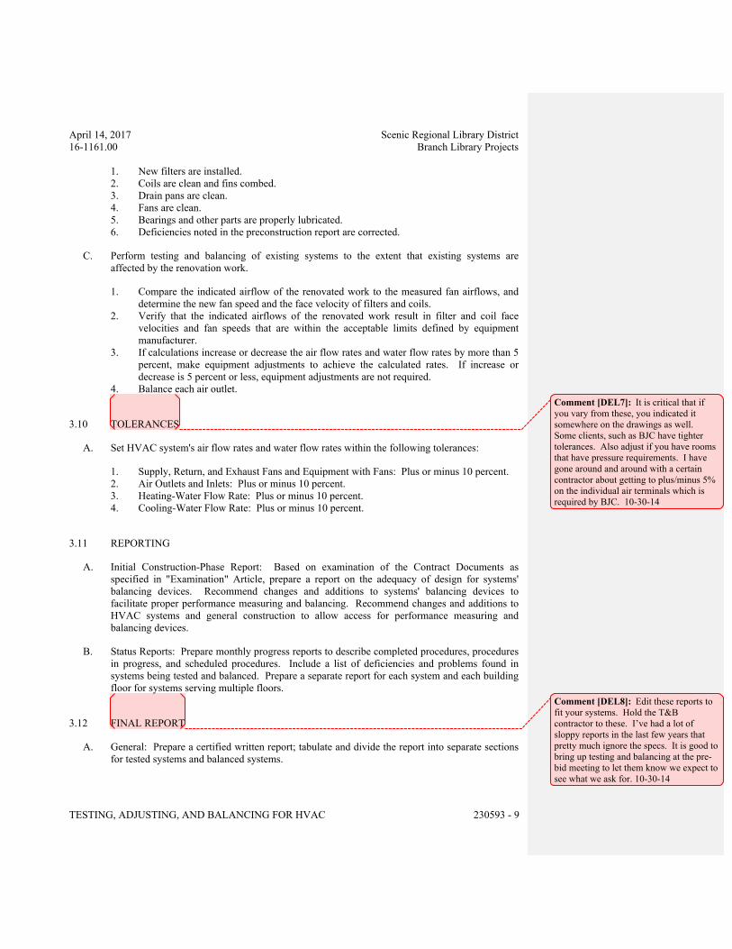
April 14, 2017 Scenic Regional Library District
16-1161.00 Branch Library Projects
TESTING, ADJUSTING, AND BALANCING FOR HVAC 230593 - 9
1. New filters are installed.
2. Coils are clean and fins combed.
3. Drain pans are clean.
4. Fans are clean.
5. Bearings and other parts are properly lubricated.
6. Deficiencies noted in the preconstruction report are corrected.
C. Perform testing and balancing of existing systems to the extent that existing systems are
affected by the renovation work.
1. Compare the indicated airflow of the renovated work to the measured fan airflows, and
determine the new fan speed and the face velocity of filters and coils.
2. Verify that the indicated airflows of the renovated work result in filter and coil face
velocities and fan speeds that are within the acceptable limits defined by equipment
manufacturer.
3. If calculations increase or decrease the air flow rates and water flow rates by more than 5
percent, make equipment adjustments to achieve the calculated rates. If increase or
decrease is 5 percent or less, equipment adjustments are not required.
4. Balance each air outlet.
3.10 TOLERANCES
A. Set HVAC system's air flow rates and water flow rates within the following tolerances:
1. Supply, Return, and Exhaust Fans and Equipment with Fans: Plus or minus 10 percent.
2. Air Outlets and Inlets: Plus or minus 10 percent.
3. Heating-Water Flow Rate: Plus or minus 10 percent.
4. Cooling-Water Flow Rate: Plus or minus 10 percent.
3.11 REPORTING
A. Initial Construction-Phase Report: Based on examination of the Contract Documents as
specified in "Examination" Article, prepare a report on the adequacy of design for systems'
balancing devices. Recommend changes and additions to systems' balancing devices to
facilitate proper performance measuring and balancing. Recommend changes and additions to
HVAC systems and general construction to allow access for performance measuring and
balancing devices.
B. Status Reports: Prepare monthly progress reports to describe completed procedures, procedures
in progress, and scheduled procedures. Include a list of deficiencies and problems found in
systems being tested and balanced. Prepare a separate report for each system and each building
floor for systems serving multiple floors.
3.12 FINAL REPORT
A. General: Prepare a certified written report; tabulate and divide the report into separate sections
for tested systems and balanced systems.
Comment [DEL7]: It is critical that if
you vary from these, you indicated it
somewhere on the drawings as well.
Some clients, such as BJC have tighter
tolerances. Also adjust if you have rooms
that have pressure requirements. I have
gone around and around with a certain
contractor about getting to plus/minus 5%
on the individual air terminals which is
required by BJC. 10-30-14
Comment [DEL8]: Edit these reports to
fit your systems. Hold the T&B
contractor to these. I’ve had a lot of
sloppy reports in the last few years that
pretty much ignore the specs. It is good to
bring up testing and balancing at the pre-
bid meeting to let them know we expect to
see what we ask for. 10-30-14
April 14, 2017 Scenic Regional Library District
16-1161.00 Branch Library Projects
TESTING, ADJUSTING, AND BALANCING FOR HVAC 230593 - 10
1. Include a certification sheet at the front of the report's binder, signed and sealed by the
certified testing and balancing engineer.
2. Include a list of instruments used for procedures, along with proof of calibration.
B. Final Report Contents: In addition to certified field-report data, include the following:
1. Fan curves.
2. Manufacturers' test data.
3. Field test reports prepared by system and equipment installers.
4. Other information relative to equipment performance; do not include Shop Drawings and
product data.
C. General Report Data: In addition to form titles and entries, include the following data:
1. Title page.
2. Name and address of the TAB contractor.
3. Project name.
4. Project location.
5. Architect's name and address.
6. Engineer's name and address.
7. Contractor's name and address.
8. Report date.
9. Signature of TAB supervisor who certifies the report.
10. Table of Contents with the total number of pages defined for each section of the report.
Number each page in the report.
11. Summary of contents including the following:
a. Indicated versus final performance.
b. Notable characteristics of systems.
c. Description of system operation sequence if it varies from the Contract
Documents.
12. Nomenclature sheets for each item of equipment.
13. Data for terminal units, including manufacturer's name, type, size, and fittings.
14. Notes to explain why certain final data in the body of reports vary from indicated values.
15. Test conditions for fans and pump performance forms including the following:
a. Settings for outdoor-, return-, and exhaust-air dampers.
b. Conditions of filters.
c. Cooling coil, wet- and dry-bulb conditions.
d. Face and bypass damper settings at coils.
e. Fan drive settings including settings and percentage of maximum pitch diameter.
f. Inlet vane settings for variable-air-volume systems.
g. Settings for supply-air, static-pressure controller.
h. Other system operating conditions that affect performance.
D. System Diagrams: Include schematic layouts of air and hydronic distribution systems. Present
each system with single-line diagram and include the following:
1. Quantities of outdoor, supply, return, and exhaust airflows.
2. Water and steam flow rates.
April 14, 2017 Scenic Regional Library District
16-1161.00 Branch Library Projects
TESTING, ADJUSTING, AND BALANCING FOR HVAC 230593 - 11
3. Duct, outlet, and inlet sizes.
4. Position of balancing devices.
E. Air-Handling-Unit Test Reports: For air-handling units with coils, include the following:
1. Unit Data:
a. Unit identification.
b. Location.
c. Make and type.
d. Model number and unit size.
e. Manufacturer's serial number.
f. Unit arrangement and class.
g. Discharge arrangement.
h. Sheave make, size inches, and bore.
i. Center-to-center dimensions of sheave, and amount of adjustments inches.
j. Number, make, and size of belts.
k. Number, type, and size of filters.
2. Motor Data:
a. Motor make, and frame type and size.
b. Horsepower and rpm.
c. Volts, phase, and hertz.
d. Full-load amperage and service factor.
e. Sheave make, size inches, and bore.
f. Center-to-center dimensions of sheave, and amount of adjustments inches.
3. Test Data (Indicated and Actual Values):
a. Total air flow rate in cfm.
b. Total system static pressure in inches wg.
c. Fan rpm.
d. Discharge static pressure in inches wg.
e. Filter static-pressure differential in inches wg.
f. Cooling-coil static-pressure differential in inches wg.
g. Heating-coil static-pressure differential in inches wg.
h. Outdoor airflow in cfm.
i. Return airflow in cfm.
j. Outdoor-air damper position.
k. Return-air damper position.
F. Apparatus-Coil Test Reports:
1. Coil Data:
a. System identification.
b. Location.
c. Coil type.
d. Number of rows.
e. Fin spacing in fins per inch o.c.
April 14, 2017 Scenic Regional Library District
16-1161.00 Branch Library Projects
TESTING, ADJUSTING, AND BALANCING FOR HVAC 230593 - 12
f. Make and model number.
g. Face area in sq. ft.
h. Tube size in NPS.
i. Tube and fin materials.
j. Circuiting arrangement.
2. Test Data (Indicated and Actual Values):
a. Air flow rate in cfm.
b. Average face velocity in fpm.
c. Air pressure drop in inches wg.
d. Outdoor-air, wet- and dry-bulb temperatures in deg F.
e. Return-air, wet- and dry-bulb temperatures in deg F.
f. Entering-air, wet- and dry-bulb temperatures in deg F.
g. Leaving-air, wet- and dry-bulb temperatures in deg F.
h. Refrigerant expansion valve and refrigerant types.
i. Refrigerant suction pressure in psig.
j. Refrigerant suction temperature in deg F.
G. Gas- and Oil-Fired Heat Apparatus Test Reports: In addition to manufacturer's factory startup
equipment reports, include the following:
1. Unit Data:
a. System identification.
b. Location.
c. Make and type.
d. Model number and unit size.
e. Manufacturer's serial number.
f. Fuel type in input data.
g. Output capacity in Btu/h.
h. Ignition type.
i. Burner-control types.
j. Motor horsepower and rpm.
k. Motor volts, phase, and hertz.
l. Motor full-load amperage and service factor.
m. Sheave make, size ininches, and bore.
n. Center-to-center dimensions of sheave, and amount of adjustments ininches.
2. Test Data (Indicated and Actual Values):
a. Total air flow rate in cfm.
b. Entering-air temperature in deg F.
c. Leaving-air temperature in deg F.
d. Air temperature differential in deg F.
e. Entering-air static pressure in inches wg.
f. Leaving-air static pressure in inches wg.
g. Air static-pressure differential in inches wg.
h. Low-fire fuel input in Btu/h.
i. High-fire fuel input in Btu/h.
j. Manifold pressure in psig.
April 14, 2017 Scenic Regional Library District
16-1161.00 Branch Library Projects
TESTING, ADJUSTING, AND BALANCING FOR HVAC 230593 - 13
k. High-temperature-limit setting in deg F.
l. Operating set point in Btu/h.
m. Motor voltage at each connection.
n. Motor amperage for each phase.
o. Heating value of fuel in Btu/h.
H. Fan Test Reports: For supply, return, and exhaust fans, include the following:
1. Fan Data:
a. System identification.
b. Location.
c. Make and type.
d. Model number and size.
e. Manufacturer's serial number.
f. Arrangement and class.
g. Sheave make, size ininches, and bore.
h. Center-to-center dimensions of sheave, and amount of adjustments ininches.
2. Motor Data:
a. Motor make, and frame type and size.
b. Horsepower and rpm.
c. Volts, phase, and hertz.
d. Full-load amperage and service factor.
e. Sheave make, size ininches, and bore.
f. Center-to-center dimensions of sheave, and amount of adjustments ininches.
g. Number, make, and size of belts.
3. Test Data (Indicated and Actual Values):
a. Total airflow rate in cfm.
b. Total system static pressure in inches wg.
c. Fan rpm.
d. Discharge static pressure in inches wg.
e. Suction static pressure in inches wg.
I. Round, Flat-Oval, and Rectangular Duct Traverse Reports: Include a diagram with a grid
representing the duct cross-section and record the following:
1. Report Data:
a. System and air-handling-unit number.
b. Location and zone.
c. Traverse air temperature in deg F.
d. Duct static pressure in inches wg.
e. Duct size inches.
f. Duct area in sq. ft.
g. Indicated air flow rate in cfm.
h. Indicated velocity in fpm.
i. Actual air flow rate in cfm.
April 14, 2017 Scenic Regional Library District
16-1161.00 Branch Library Projects
TESTING, ADJUSTING, AND BALANCING FOR HVAC 230593 - 14
j. Actual average velocity in fpm.
k. Barometric pressure in psig.
J. Instrument Calibration Reports:
1. Report Data:
a. Instrument type and make.
b. Serial number.
c. Application.
d. Dates of use.
e. Dates of calibration.
3.13 INSPECTIONS
A. Final Inspection:
1. After initial inspection is complete and documentation by random checks verifies that
testing and balancing are complete and accurately documented in the final report, request
that a final inspection be made by Architect.
2. The TAB contractor's test and balance engineer shall conduct the inspection in the
presence of Architect.
3. Architect shall randomly select measurements, documented in the final report, to be
rechecked. Rechecking shall be limited to either 10 percent of the total measurements
recorded or the extent of measurements that can be accomplished in a normal 8-hour
business day.
4. If rechecks yield measurements that differ from the measurements documented in the
final report by more than the tolerances allowed, the measurements shall be noted as
"FAILED."
5. If the number of "FAILED" measurements is greater than 10 percent of the total
measurements checked during the final inspection, the testing and balancing shall be
considered incomplete and shall be rejected.
B. TAB Work will be considered defective if it does not pass final inspections. If TAB Work fails,
proceed as follows:
1. Recheck all measurements and make adjustments. Revise the final report and balancing
device settings to include all changes; resubmit the final report and request a second final
inspection.
2. If the second final inspection also fails, Owner may contract the services of another TAB
contractor to complete TAB Work according to the Contract Documents and deduct the
cost of the services from the original TAB contractor's final payment.
C. Prepare test and inspection reports.
3.14 ADDITIONAL TESTS
A. Within 90 days of completing TAB, perform additional TAB to verify that balanced conditions
are being maintained throughout and to correct unusual conditions.
April 14, 2017 Scenic Regional Library District
16-1161.00 Branch Library Projects
TESTING, ADJUSTING, AND BALANCING FOR HVAC 230593 - 15
B. Seasonal Periods: If initial TAB procedures were not performed during near-peak summer and
winter conditions, perform additional TAB during near-peak summer and winter conditions.
END OF SECTION 230593
Comment [DEL9]: This is not a trivial
statement. Depending on the system type,
we should require that some system be
retested at the peaks, such as cooling
towers in the summer and in the winter if
used for economizers. Boilers in the
winter for full load and summer for part
load. 10-30-14

April 14, 2017 Scenic Regional Library District
16-1161.00 Branch Library Projects
DUCT INSULATION 230713 - 1
SECTION 230713 - DUCT INSULATION
ALL LIBRARIES
PART 1 - GENERAL
1.1 RELATED DOCUMENTS
A. Drawings and general provisions of the Contract, including General and Supplementary
Conditions and Division 01 Specification Sections, apply to this Section.
1.2 SUMMARY
A. Section includes insulating the following duct services:
1. Indoor, concealed supply and outdoor air.
2. Indoor, exposed supply and outdoor air.
3. Indoor, concealed return located in unconditioned space.
4. Indoor, exposed return located in unconditioned space.
5. Indoor, concealed exhaust between isolation damper and penetration of building exterior.
6. Outdoor, concealed supply and return.
7. Outdoor, exposed supply and return.
B. Related Sections:
1. Section 230716 "HVAC Equipment Insulation."
2. Section 230719 "HVAC Piping Insulation."
3. Section 233113 "Metal Ducts" for duct liners.
1.3 ACTION SUBMITTALS
A. Product Data: For each type of product indicated. Include thermal conductivity, water-vapor
permeance thickness, and jackets (both factory- and field-applied if any).
B. Shop Drawings: Include plans, elevations, sections, details, and attachments to other work.
1. Detail application of protective shields, saddles, and inserts at hangers for each type of
insulation and hanger.
2. Detail insulation application at elbows, fittings, dampers, specialties and flanges for each
type of insulation.
3. Detail application of field-applied jackets.
4. Detail application at linkages of control devices.
Comment [DEL1]: Look for this during
punch lists. The issue is sweating if the
duct is uninsulated. 10-30-14
April 14, 2017 Scenic Regional Library District
16-1161.00 Branch Library Projects
DUCT INSULATION 230713 - 2
1.4 INFORMATIONAL SUBMITTALS
A. Qualification Data: For qualified Installer.
B. Material Test Reports: From a qualified testing agency acceptable to authorities having
jurisdiction indicating, interpreting, and certifying test results for compliance of insulation
materials, sealers, attachments, cements, and jackets, with requirements indicated. Include
dates of tests and test methods employed.
C. Field quality-control reports.
1.5 QUALITY ASSURANCE
A. Installer Qualifications: Skilled mechanics who have successfully completed an apprenticeship
program or another craft training program certified by the Department of Labor, Bureau of
Apprenticeship and Training.
B. Surface-Burning Characteristics: For insulation and related materials, as determined by testing
identical products according to ASTM E 84, by a testing agency acceptable to authorities
having jurisdiction. Factory label insulation and jacket materials and adhesive, mastic, tapes,
and cement material containers, with appropriate markings of applicable testing agency.
1. Insulation Installed Indoors: Flame-spread index of 25 or less, and smoke-developed
index of 50 or less.
2. Insulation Installed Outdoors: Flame-spread index of 75 or less, and smoke-developed
index of 150 or less.
1.6 DELIVERY, STORAGE, AND HANDLING
A. Packaging: Insulation material containers shall be marked by manufacturer with appropriate
ASTM standard designation, type and grade, and maximum use temperature.
1.7 COORDINATION
A. Coordinate sizes and locations of supports, hangers, and insulation shields specified in
Section 230529 "Hangers and Supports for HVAC Piping and Equipment."
B. Coordinate clearance requirements with duct Installer for duct insulation application. Before
preparing ductwork Shop Drawings, establish and maintain clearance requirements for
installation of insulation and field-applied jackets and finishes and for space required for
maintenance.
C. Coordinate installation and testing of heat tracing.
April 14, 2017 Scenic Regional Library District
16-1161.00 Branch Library Projects
DUCT INSULATION 230713 - 3
1.8 SCHEDULING
A. Schedule insulation application after pressure testing systems and, where required, after
installing and testing heat tracing. Insulation application may begin on segments that have
satisfactory test results.
B. Complete installation and concealment of plastic materials as rapidly as possible in each area of
construction.
PART 2 - PRODUCTS
2.1 INSULATION MATERIALS
A. Comply with requirements in "Duct Insulation Schedule, General," "Indoor Duct and Plenum
Insulation Schedule," and "Aboveground, Outdoor Duct and Plenum Insulation Schedule"
articles for where insulating materials shall be applied.
B. Products shall not contain asbestos, lead, mercury, or mercury compounds.
C. Products that come in contact with stainless steel shall have a leachable chloride content of less
than 50 ppm when tested according to ASTM C 871.
D. Insulation materials for use on austenitic stainless steel shall be qualified as acceptable
according to ASTM C 795.
E. Foam insulation materials shall not use CFC or HCFC blowing agents in the manufacturing
process.
F. Flexible Elastomeric Insulation: Closed-cell, sponge- or expanded-rubber materials. Comply
with ASTM C 534, Type II for sheet materials.
1. Products: Subject to compliance with requirements, provide one of the following:
a. Aeroflex USA, Inc.; Aerocel.
b. Armacell LLC; AP Armaflex.
c. K-Flex USA; Insul-Sheet, K-Flex Gray Duct Liner, and K-FLEX LS.
G. Mineral-Fiber Blanket Insulation: Mineral or glass fibers bonded with a thermosetting resin.
Comply with ASTM C 553, Type II and ASTM C 1290, Type II with factory-applied vinyl
jacket. Factory-applied jacket requirements are specified in "Factory-Applied Jackets" Article.
1. Products: Subject to compliance with requirements, provide one of the following:
a. CertainTeed Corp.; SoftTouch Duct Wrap.
b. Johns Manville; Microlite.
c. Knauf Insulation; Friendly Feel Duct Wrap.
d. Manson Insulation Inc.; Alley Wrap.
e. Owens Corning; SOFTR All-Service Duct Wrap.
April 14, 2017 Scenic Regional Library District
16-1161.00 Branch Library Projects
DUCT INSULATION 230713 - 4
2.2 ADHESIVES
A. Materials shall be compatible with insulation materials, jackets, and substrates and for bonding
insulation to itself and to surfaces to be insulated unless otherwise indicated.
B. Flexible Elastomeric Adhesive: Comply with MIL-A-24179A, Type II, Class I.
1. Products: Subject to compliance with requirements, provide one of the following:
a. Aeroflex USA, Inc.; Aeroseal.
b. Armacell LLC; Armaflex 520 Adhesive.
c. Foster Brand, Specialty Construction Brands, Inc., a business of H. B. Fuller
Company; 85-75.K-Flex USA; R-373 Contact Adhesive.
2. For indoor applications, adhesive shall have a VOC content of 50 g/L or less when
calculated according to 40 CFR 59, Subpart D (EPA Method 24).
3. Adhesive shall comply with the testing and product requirements of the California
Department of Health Services' "Standard Practice for the Testing of Volatile Organic
Emissions from Various Sources Using Small-Scale Environmental Chambers."
C. Mineral-Fiber Adhesive: Comply with MIL-A-3316C, Class 2, Grade A.
1. Products: Subject to compliance with requirements, provide one of the following:
a. Childers Brand, Specialty Construction Brands, Inc., a business of H. B. Fuller
Company; CP-127.Eagle Bridges - Marathon Industries; 225.
b. Foster Brand, Specialty Construction Brands, Inc., a business of H. B. Fuller
Company; 85-60/85-70.Mon-Eco Industries, Inc.; 22-25.
2. For indoor applications, adhesive shall have a VOC content of 80 g/L or less when
calculated according to 40 CFR 59, Subpart D (EPA Method 24).
3. Adhesive shall comply with the testing and product requirements of the California
Department of Health Services' "Standard Practice for the Testing of Volatile Organic
Emissions from Various Sources Using Small-Scale Environmental Chambers."
D. ASJ Adhesive, and FSK Jacket Adhesive: Comply with MIL-A-3316C, Class 2, Grade A for
bonding insulation jacket lap seams and joints.
1. Products: Subject to compliance with requirements, provide one of the following:
a. Childers Brand, Specialty Construction Brands, Inc., a business of H. B. Fuller
Company; CP-82.
b. Eagle Bridges - Marathon Industries; 225.
c. Foster Brand, Specialty Construction Brands, Inc., a business of H. B. Fuller
Company; 85-50.Mon-Eco Industries, Inc.; 22-25.
2. For indoor applications, adhesive shall have a VOC content of 50 g/L or less when
calculated according to 40 CFR 59, Subpart D (EPA Method 24).
3. Adhesive shall comply with the testing and product requirements of the California
Department of Health Services' "Standard Practice for the Testing of Volatile Organic
Emissions from Various Sources Using Small-Scale Environmental Chambers."
April 14, 2017 Scenic Regional Library District
16-1161.00 Branch Library Projects
DUCT INSULATION 230713 - 5
4. For indoor applications, adhesive shall have a VOC content of 50 g/L or less when
calculated according to 40 CFR 59, Subpart D (EPA Method 24).
5. Adhesive shall comply with the testing and product requirements of the California
Department of Health Services' "Standard Practice for the Testing of Volatile Organic
Emissions from Various Sources Using Small-Scale Environmental Chambers."
2.3 MASTICS
A. Materials shall be compatible with insulation materials, jackets, and substrates; comply with
MIL-PRF-19565C, Type II.
1. For indoor applications, use mastics that have a VOC content of 50 g/L or less when
calculated according to 40 CFR 59, Subpart D (EPA Method 24).
B. Vapor-Barrier Mastic: Water based; suitable for indoor use on below ambient services.
1. Products: Subject to compliance with requirements, provide one of the following:
a. Foster Brand, Specialty Construction Brands, Inc., a business of H. B. Fuller
Company; 30-80/30-90.
b. Vimasco Corporation; 749.
2. Water-Vapor Permeance: ASTM E 96/E 96M, Procedure B, 0.013 perm at 43-mil dry
film thickness.
3. Service Temperature Range: Minus 20 to plus 180 deg F.
4. Solids Content: ASTM D 1644, 58 percent by volume and 70 percent by weight.
5. Color: White.
C. Vapor-Barrier Mastic: Solvent based; suitable for indoor use on below ambient services.
1. Products: Subject to compliance with requirements, provide one of the following:
a. Childers Brand, Specialty Construction Brands, Inc., a business of H. B. Fuller
Company; CP-30.
b. Eagle Bridges - Marathon Industries; 501.
c. Foster Brand, Specialty Construction Brands, Inc., a business of H. B. Fuller
Company; 30-35.
d. Mon-Eco Industries, Inc.; 55-10.
2. Water-Vapor Permeance: ASTM F 1249, 0.05 perm at 35-mil dry film thickness.
3. Service Temperature Range: 0 to 180 deg F.
4. Solids Content: ASTM D 1644, 44 percent by volume and 62 percent by weight.
5. Color: White.
D. Vapor-Barrier Mastic: Solvent based; suitable for outdoor use on below ambient services.
1. Products: Subject to compliance with requirements, provide one of the following:
a. Childers Brand, Specialty Construction Brands, Inc., a business of H. B. Fuller
Company; Encacel.
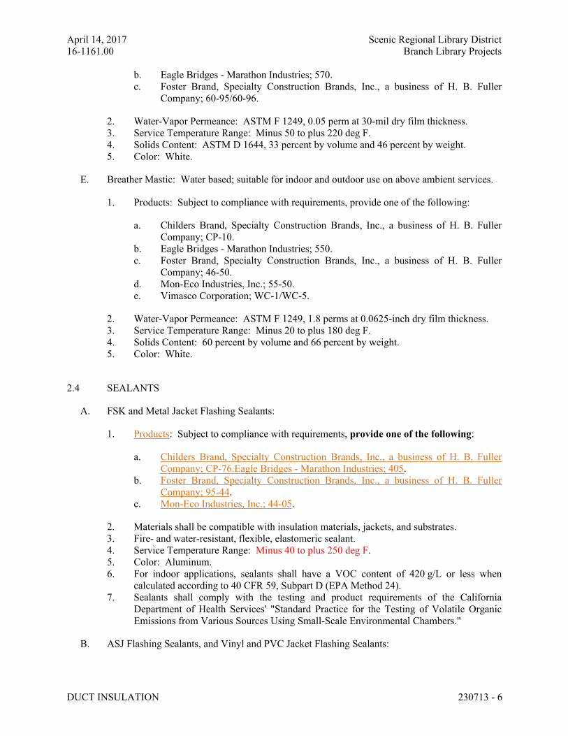
April 14, 2017 Scenic Regional Library District
16-1161.00 Branch Library Projects
DUCT INSULATION 230713 - 6
b. Eagle Bridges - Marathon Industries; 570.
c. Foster Brand, Specialty Construction Brands, Inc., a business of H. B. Fuller
Company; 60-95/60-96.
2. Water-Vapor Permeance: ASTM F 1249, 0.05 perm at 30-mil dry film thickness.
3. Service Temperature Range: Minus 50 to plus 220 deg F.
4. Solids Content: ASTM D 1644, 33 percent by volume and 46 percent by weight.
5. Color: White.
E. Breather Mastic: Water based; suitable for indoor and outdoor use on above ambient services.
1. Products: Subject to compliance with requirements, provide one of the following:
a. Childers Brand, Specialty Construction Brands, Inc., a business of H. B. Fuller
Company; CP-10.
b. Eagle Bridges - Marathon Industries; 550.
c. Foster Brand, Specialty Construction Brands, Inc., a business of H. B. Fuller
Company; 46-50.
d. Mon-Eco Industries, Inc.; 55-50.
e. Vimasco Corporation; WC-1/WC-5.
2. Water-Vapor Permeance: ASTM F 1249, 1.8 perms at 0.0625-inch dry film thickness.
3. Service Temperature Range: Minus 20 to plus 180 deg F.
4. Solids Content: 60 percent by volume and 66 percent by weight.
5. Color: White.
2.4 SEALANTS
A. FSK and Metal Jacket Flashing Sealants:
1. Products: Subject to compliance with requirements, provide one of the following:
a. Childers Brand, Specialty Construction Brands, Inc., a business of H. B. Fuller
Company; CP-76.Eagle Bridges - Marathon Industries; 405.
b. Foster Brand, Specialty Construction Brands, Inc., a business of H. B. Fuller
Company; 95-44.
c. Mon-Eco Industries, Inc.; 44-05.
2. Materials shall be compatible with insulation materials, jackets, and substrates.
3. Fire- and water-resistant, flexible, elastomeric sealant.
4. Service Temperature Range: Minus 40 to plus 250 deg F.
5. Color: Aluminum.
6. For indoor applications, sealants shall have a VOC content of 420 g/L or less when
calculated according to 40 CFR 59, Subpart D (EPA Method 24).
7. Sealants shall comply with the testing and product requirements of the California
Department of Health Services' "Standard Practice for the Testing of Volatile Organic
Emissions from Various Sources Using Small-Scale Environmental Chambers."
B. ASJ Flashing Sealants, and Vinyl and PVC Jacket Flashing Sealants:
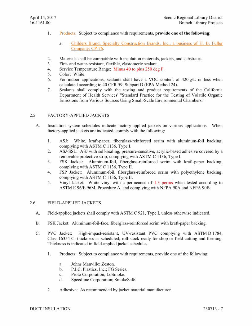
April 14, 2017 Scenic Regional Library District
16-1161.00 Branch Library Projects
DUCT INSULATION 230713 - 7
1. Products: Subject to compliance with requirements, provide one of the following:
a. Childers Brand, Specialty Construction Brands, Inc., a business of H. B. Fuller
Company; CP-76.
2. Materials shall be compatible with insulation materials, jackets, and substrates.
3. Fire- and water-resistant, flexible, elastomeric sealant.
4. Service Temperature Range: Minus 40 to plus 250 deg F.
5. Color: White.
6. For indoor applications, sealants shall have a VOC content of 420 g/L or less when
calculated according to 40 CFR 59, Subpart D (EPA Method 24).
7. Sealants shall comply with the testing and product requirements of the California
Department of Health Services' "Standard Practice for the Testing of Volatile Organic
Emissions from Various Sources Using Small-Scale Environmental Chambers."
2.5 FACTORY-APPLIED JACKETS
A. Insulation system schedules indicate factory-applied jackets on various applications. When
factory-applied jackets are indicated, comply with the following:
1. ASJ: White, kraft-paper, fiberglass-reinforced scrim with aluminum-foil backing;
complying with ASTM C 1136, Type I.
2. ASJ-SSL: ASJ with self-sealing, pressure-sensitive, acrylic-based adhesive covered by a
removable protective strip; complying with ASTM C 1136, Type I.
3. FSK Jacket: Aluminum-foil, fiberglass-reinforced scrim with kraft-paper backing;
complying with ASTM C 1136, Type II.
4. FSP Jacket: Aluminum-foil, fiberglass-reinforced scrim with polyethylene backing;
complying with ASTM C 1136, Type II.
5. Vinyl Jacket: White vinyl with a permeance of 1.3 perms when tested according to
ASTM E 96/E 96M, Procedure A, and complying with NFPA 90A and NFPA 90B.
2.6 FIELD-APPLIED JACKETS
A. Field-applied jackets shall comply with ASTM C 921, Type I, unless otherwise indicated.
B. FSK Jacket: Aluminum-foil-face, fiberglass-reinforced scrim with kraft-paper backing.
C. PVC Jacket: High-impact-resistant, UV-resistant PVC complying with ASTM D 1784,
Class 16354-C; thickness as scheduled; roll stock ready for shop or field cutting and forming.
Thickness is indicated in field-applied jacket schedules.
1. Products: Subject to compliance with requirements, provide one of the following:
a. Johns Manville; Zeston.
b. P.I.C. Plastics, Inc.; FG Series.
c. Proto Corporation; LoSmoke.
d. Speedline Corporation; SmokeSafe.
2. Adhesive: As recommended by jacket material manufacturer.
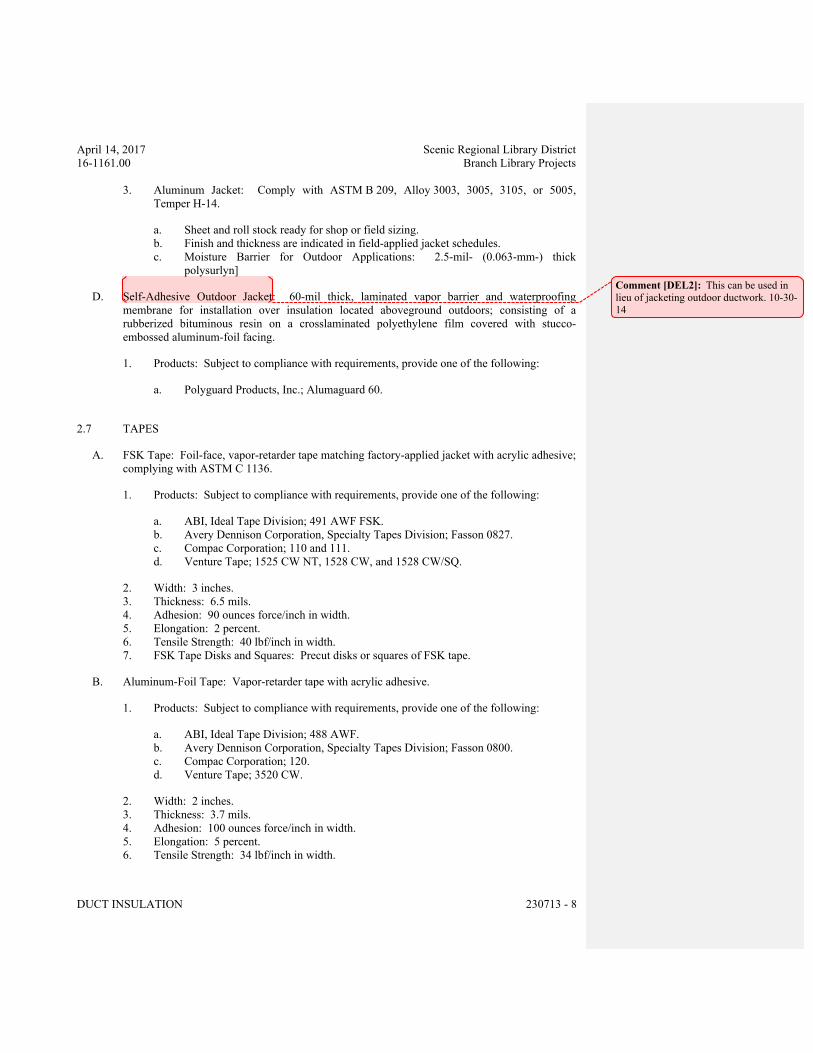
April 14, 2017 Scenic Regional Library District
16-1161.00 Branch Library Projects
DUCT INSULATION 230713 - 8
3. Aluminum Jacket: Comply with ASTM B 209, Alloy 3003, 3005, 3105, or 5005,
Temper H-14.
a. Sheet and roll stock ready for shop or field sizing.
b. Finish and thickness are indicated in field-applied jacket schedules.
c. Moisture Barrier for Outdoor Applications: 2.5-mil- (0.063-mm-) thick
polysurlyn]
D. Self-Adhesive Outdoor Jacket: 60-mil thick, laminated vapor barrier and waterproofing
membrane for installation over insulation located aboveground outdoors; consisting of a
rubberized bituminous resin on a crosslaminated polyethylene film covered with stucco-
embossed aluminum-foil facing.
1. Products: Subject to compliance with requirements, provide one of the following:
a. Polyguard Products, Inc.; Alumaguard 60.
2.7 TAPES
A. FSK Tape: Foil-face, vapor-retarder tape matching factory-applied jacket with acrylic adhesive;
complying with ASTM C 1136.
1. Products: Subject to compliance with requirements, provide one of the following:
a. ABI, Ideal Tape Division; 491 AWF FSK.
b. Avery Dennison Corporation, Specialty Tapes Division; Fasson 0827.
c. Compac Corporation; 110 and 111.
d. Venture Tape; 1525 CW NT, 1528 CW, and 1528 CW/SQ.
2. Width: 3 inches.
3. Thickness: 6.5 mils.
4. Adhesion: 90 ounces force/inch in width.
5. Elongation: 2 percent.
6. Tensile Strength: 40 lbf/inch in width.
7. FSK Tape Disks and Squares: Precut disks or squares of FSK tape.
B. Aluminum-Foil Tape: Vapor-retarder tape with acrylic adhesive.
1. Products: Subject to compliance with requirements, provide one of the following:
a. ABI, Ideal Tape Division; 488 AWF.
b. Avery Dennison Corporation, Specialty Tapes Division; Fasson 0800.
c. Compac Corporation; 120.
d. Venture Tape; 3520 CW.
2. Width: 2 inches.
3. Thickness: 3.7 mils.
4. Adhesion: 100 ounces force/inch in width.
5. Elongation: 5 percent.
6. Tensile Strength: 34 lbf/inch in width.
Comment [DEL2]: This can be used in
lieu of jacketing outdoor ductwork. 10-30-
14
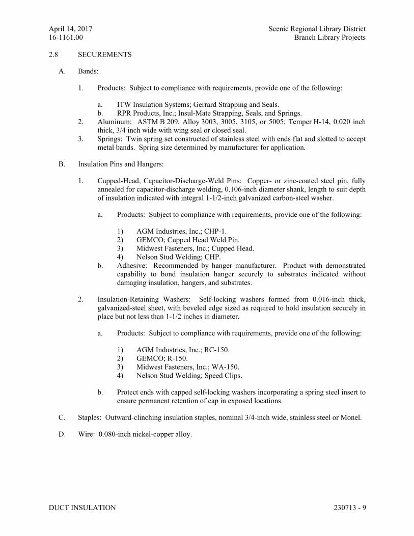
April 14, 2017 Scenic Regional Library District
16-1161.00 Branch Library Projects
DUCT INSULATION 230713 - 9
2.8 SECUREMENTS
A. Bands:
1. Products: Subject to compliance with requirements, provide one of the following:
a. ITW Insulation Systems; Gerrard Strapping and Seals.
b. RPR Products, Inc.; Insul-Mate Strapping, Seals, and Springs.
2. Aluminum: ASTM B 209, Alloy 3003, 3005, 3105, or 5005; Temper H-14, 0.020 inch
thick, 3/4 inch wide with wing seal or closed seal.
3. Springs: Twin spring set constructed of stainless steel with ends flat and slotted to accept
metal bands. Spring size determined by manufacturer for application.
B. Insulation Pins and Hangers:
1. Cupped-Head, Capacitor-Discharge-Weld Pins: Copper- or zinc-coated steel pin, fully
annealed for capacitor-discharge welding, 0.106-inch diameter shank, length to suit depth
of insulation indicated with integral 1-1/2-inch galvanized carbon-steel washer.
a. Products: Subject to compliance with requirements, provide one of the following:
1) AGM Industries, Inc.; CHP-1.
2) GEMCO; Cupped Head Weld Pin.
3) Midwest Fasteners, Inc.; Cupped Head.
4) Nelson Stud Welding; CHP.
b. Adhesive: Recommended by hanger manufacturer. Product with demonstrated
capability to bond insulation hanger securely to substrates indicated without
damaging insulation, hangers, and substrates.
2. Insulation-Retaining Washers: Self-locking washers formed from 0.016-inch thick,
galvanized-steel sheet, with beveled edge sized as required to hold insulation securely in
place but not less than 1-1/2 inches in diameter.
a. Products: Subject to compliance with requirements, provide one of the following:
1) AGM Industries, Inc.; RC-150.
2) GEMCO; R-150.
3) Midwest Fasteners, Inc.; WA-150.
4) Nelson Stud Welding; Speed Clips.
b. Protect ends with capped self-locking washers incorporating a spring steel insert to
ensure permanent retention of cap in exposed locations.
C. Staples: Outward-clinching insulation staples, nominal 3/4-inch wide, stainless steel or Monel.
D. Wire: 0.080-inch nickel-copper alloy.
April 14, 2017 Scenic Regional Library District
16-1161.00 Branch Library Projects
DUCT INSULATION 230713 - 10
2.9 CORNER ANGLES
A. Aluminum Corner Angles: 0.040 inch thick, minimum 1 by 1 inch, aluminum according to
ASTM B 209, Alloy 3003, 3005, 3105, or 5005; Temper H-14.
B. Stainless-Steel Corner Angles: 0.024 inch thick, minimum 1 by 1 inch, stainless steel according
to ASTM A 167 or ASTM A 240/A 240M, Type 304 or Type 316.
PART 3 - EXECUTION
3.1 EXAMINATION
A. Examine substrates and conditions for compliance with requirements for installation tolerances
and other conditions affecting performance of insulation application.
1. Verify that systems to be insulated have been tested and are free of defects.
2. Verify that surfaces to be insulated are clean and dry.
B. Proceed with installation only after unsatisfactory conditions have been corrected.
3.2 PREPARATION
A. Surface Preparation: Clean and dry surfaces to receive insulation. Remove materials that will
adversely affect insulation application.
3.3 GENERAL INSTALLATION REQUIREMENTS
A. Install insulation materials, accessories, and finishes with smooth, straight, and even surfaces;
free of voids throughout the length of ducts and fittings.
B. Install insulation materials, vapor barriers or retarders, jackets, and thicknesses required for
each item of duct system as specified in insulation system schedules.
C. Install accessories compatible with insulation materials and suitable for the service. Install
accessories that do not corrode, soften, or otherwise attack insulation or jacket in either wet or
dry state.
D. Install insulation with longitudinal seams at top and bottom of horizontal runs.
E. Install multiple layers of insulation with longitudinal and end seams staggered.
F. Keep insulation materials dry during application and finishing.
G. Install insulation with tight longitudinal seams and end joints. Bond seams and joints with
adhesive recommended by insulation material manufacturer.
H. Install insulation with least number of joints practical.
April 14, 2017 Scenic Regional Library District
16-1161.00 Branch Library Projects
DUCT INSULATION 230713 - 11
I. Where vapor barrier is indicated, seal joints, seams, and penetrations in insulation at hangers,
supports, anchors, and other projections with vapor-barrier mastic.
1. Install insulation continuously through hangers and around anchor attachments.
2. For insulation application where vapor barriers are indicated, extend insulation on anchor
legs from point of attachment to supported item to point of attachment to structure. Taper
and seal ends at attachment to structure with vapor-barrier mastic.
3. Install insert materials and install insulation to tightly join the insert. Seal insulation to
insulation inserts with adhesive or sealing compound recommended by insulation
material manufacturer.
J. Apply adhesives, mastics, and sealants at manufacturer's recommended coverage rate and wet
and dry film thicknesses.
K. Install insulation with factory-applied jackets as follows:
1. Draw jacket tight and smooth.
2. Cover circumferential joints with 3-inchwide strips, of same material as insulation jacket.
Secure strips with adhesive and outward clinching staples along both edges of strip,
spaced 4 inches o.c.
3. Overlap jacket longitudinal seams at least 1-1/2 inches. Clean and dry surface to receive
self-sealing lap. Staple laps with outward clinching staples along edge at 4 inches o.c.
a. For below ambient services, apply vapor-barrier mastic over staples.
4. Cover joints and seams with tape, according to insulation material manufacturer's written
instructions, to maintain vapor seal.
5. Where vapor barriers are indicated, apply vapor-barrier mastic on seams and joints and at
ends adjacent to duct flanges and fittings.
L. Cut insulation in a manner to avoid compressing insulation more than 75 percent of its nominal
thickness.
M. Finish installation with systems at operating conditions. Repair joint separations and cracking
due to thermal movement.
N. Repair damaged insulation facings by applying same facing material over damaged areas.
Extend patches at least 4 inches beyond damaged areas. Adhere, staple, and seal patches similar
to butt joints.
3.4 PENETRATIONS
A. Insulation Installation at Roof Penetrations: Install insulation continuously through roof
penetrations.
1. Seal penetrations with flashing sealant.
2. For applications requiring only indoor insulation, terminate insulation above roof surface
and seal with joint sealant. For applications requiring indoor and outdoor insulation,
install insulation for outdoor applications tightly joined to indoor insulation ends. Seal
joint with joint sealant.
April 14, 2017 Scenic Regional Library District
16-1161.00 Branch Library Projects
DUCT INSULATION 230713 - 12
3. Extend jacket of outdoor insulation outside roof flashing at least 2 inches below top of
roof flashing.
4. Seal jacket to roof flashing with flashing sealant.
B. Insulation Installation at Aboveground Exterior Wall Penetrations: Install insulation
continuously through wall penetrations.
1. Seal penetrations with flashing sealant.
2. For applications requiring only indoor insulation, terminate insulation inside wall surface
and seal with joint sealant. For applications requiring indoor and outdoor insulation,
install insulation for outdoor applications tightly joined to indoor insulation ends. Seal
joint with joint sealant.
3. Extend jacket of outdoor insulation outside wall flashing and overlap wall flashing at
least 2 inches.
4. Seal jacket to wall flashing with flashing sealant.
C. Insulation Installation at Interior Wall and Partition Penetrations (That Are Not Fire Rated):
Install insulation continuously through walls and partitions.
D. Insulation Installation at Fire-Rated Wall and Partition Penetrations: Terminate insulation at
fire damper sleeves for fire-rated wall and partition penetrations. Externally insulate damper
sleeves to match adjacent insulation and overlap duct insulation at least 2 inches.
1. Comply with requirements in Section 078413 "Penetration Firestopping and fire-resistive
joint sealers”.
E. Insulation Installation at Floor Penetrations:
1. Duct: For penetrations through fire-rated assemblies, terminate insulation at fire damper
sleeves and externally insulate damper sleeve beyond floor to match adjacent duct
insulation. Overlap damper sleeve and duct insulation at least 2 inches.
2. Seal penetrations through fire-rated assemblies. Comply with requirements in
Section 078413 "Penetration Firestopping."
3.5 INSTALLATION OF FLEXIBLE ELASTOMERIC INSULATION
A. Seal longitudinal seams and end joints with manufacturer's recommended adhesive to eliminate
openings in insulation that allow passage of air to surface being insulated.
3.6 INSTALLATION OF MINERAL-FIBER INSULATION
A. Blanket Insulation Installation on Ducts and Plenums: Secure with adhesive and insulation
pins.
1. Apply adhesives according to manufacturer's recommended coverage rates per unit area,
for 100 percent coverage of duct and plenum surfaces.
2. Apply adhesive to entire circumference of ducts and to all surfaces of fittings and
transitions.
April 14, 2017 Scenic Regional Library District
16-1161.00 Branch Library Projects
DUCT INSULATION 230713 - 13
3. Install either capacitor-discharge-weld pins and speed washers or cupped-head, capacitor-
discharge-weld pins on sides and bottom of horizontal ducts and sides of vertical ducts as
follows:
a. On duct sides with dimensions 18 inches and smaller, place pins along longitudinal
centerline of duct. Space 3 inches maximum from insulation end joints, and 16
inches o.c.
b. On duct sides with dimensions larger than 18 inches, place pins 16 inches o.c. each
way, and 3 inches maximum from insulation joints. Install additional pins to hold
insulation tightly against surface at cross bracing.
c. Pins may be omitted from top surface of horizontal, rectangular ducts and plenums.
d. Do not overcompress insulation during installation.
e. Impale insulation over pins and attach speed washers.
f. Cut excess portion of pins extending beyond speed washers or bend parallel with
insulation surface. Cover exposed pins and washers with tape matching insulation
facing.
4. For ducts and plenums with surface temperatures below ambient, install a continuous
unbroken vapor barrier. Create a facing lap for longitudinal seams and end joints with
insulation by removing 2 inches from one edge and one end of insulation segment.
Secure laps to adjacent insulation section with 1/2-inch outward-clinching staples, 1 inch
o.c. Install vapor barrier consisting of factory- or field-applied jacket, adhesive, vapor-
barrier mastic, and sealant at joints, seams, and protrusions.
a. Repair punctures, tears, and penetrations with tape or mastic to maintain vapor-
barrier seal.
b. Install vapor stops for ductwork and plenums operating below 50 deg F at 18-foot
intervals. Vapor stops shall consist of vapor-barrier mastic applied in a Z-shaped
pattern over insulation face, along butt end of insulation, and over the surface.
Cover insulation face and surface to be insulated a width equal to two times the
insulation thickness, but not less than 3 inches.
5. Overlap unfaced blankets a minimum of 2 inches on longitudinal seams and end joints.
At end joints, secure with steel bands spaced a maximum of 18 inches o.c.
6. Install insulation on rectangular duct elbows and transitions with a full insulation section
for each surface. Install insulation on round and flat-oval duct elbows with individually
mitered gores cut to fit the elbow.
7. Insulate duct stiffeners, hangers, and flanges that protrude beyond insulation surface with
6-inch- wide strips of same material used to insulate duct. Secure on alternating sides of
stiffener, hanger, and flange with pins spaced 6 inches o.c.
3.7 FIELD-APPLIED JACKET INSTALLATION
A. Where glass-cloth jackets are indicated, install directly over bare insulation or insulation with
factory-applied jackets.
1. Draw jacket smooth and tight to surface with 2-inch overlap at seams and joints.
2. Embed glass cloth between two 0.062-inch thick coats of lagging adhesive.
3. Completely encapsulate insulation with coating, leaving no exposed insulation.
April 14, 2017 Scenic Regional Library District
16-1161.00 Branch Library Projects
DUCT INSULATION 230713 - 14
B. Where FSK jackets are indicated, install as follows:
1. Draw jacket material smooth and tight.
2. Install lap or joint strips with same material as jacket.
3. Secure jacket to insulation with manufacturer's recommended adhesive.
4. Install jacket with 1-1/2-inch laps at longitudinal seams and 3-inch wide joint strips at
end joints.
5. Seal openings, punctures, and breaks in vapor-retarder jackets and exposed insulation
with vapor-barrier mastic.
C. Where PVC jackets are indicated, install with 1-inch overlap at longitudinal seams and end
joints; for horizontal applications, install with longitudinal seams along top and bottom of tanks
and vessels. Seal with manufacturer's recommended adhesive.
1. Apply two continuous beads of adhesive to seams and joints, one bead under lap and the
finish bead along seam and joint edge.
D. Where metal jackets are indicated, install with 2-inch overlap at longitudinal seams and end
joints. Overlap longitudinal seams arranged to shed water. Seal end joints with weatherproof
sealant recommended by insulation manufacturer. Secure jacket with stainless-steel bands 12
inches o.c. and at end joints.
3.8 FINISHES
A. Insulation with ASJ, Glass-Cloth, or Other Paintable Jacket Material: Paint jacket with paint
system identified below and as specified in Section 099113 "Exterior Painting" and
Section 099123 "Interior Painting."
1. Flat Acrylic Finish: Two finish coats over a primer that is compatible with jacket
material and finish coat paint. Add fungicidal agent to render fabric mildew proof.
a. Finish Coat Material: Interior, flat, latex-emulsion size.
B. Flexible Elastomeric Thermal Insulation: After adhesive has fully cured, apply two coats of
insulation manufacturer's recommended protective coating.
C. Color: Final color as selected by Architect. Vary first and second coats to allow visual
inspection of the completed Work.
D. Do not field paint aluminum or stainless-steel jackets.
3.9 DUCT INSULATION SCHEDULE, GENERAL
A. Plenums and Ducts Requiring Insulation:
1. Indoor, concealed supply and outdoor air.
2. Indoor, exposed supply and outdoor air.
3. Indoor, concealed return located in unconditioned space.
4. Indoor, exposed return located in unconditioned space.
April 14, 2017 Scenic Regional Library District
16-1161.00 Branch Library Projects
DUCT INSULATION 230713 - 15
5. Indoor, concealed, Type I, commercial, kitchen hood exhaust.
6. Indoor, exposed, Type I, commercial, kitchen hood exhaust.
7. Indoor, concealed oven and warewash exhaust.
8. Indoor, exposed oven and warewash exhaust.
9. Indoor, concealed exhaust between isolation damper and penetration of building exterior.
10. Indoor, exposed exhaust between isolation damper and penetration of building exterior.
11. Outdoor, concealed supply and return.
12. Outdoor, exposed supply and return.
B. Items Not Insulated:
1. Fibrous-glass ducts.
2. Metal ducts with duct liner of sufficient thickness to comply with energy code and
ASHRAE/IESNA 90.1.
3. Factory-insulated flexible ducts.
4. Factory-insulated plenums and casings.
5. Flexible connectors.
6. Vibration-control devices.
7. Factory-insulated access panels and doors.
3.10 INDOOR DUCT AND PLENUM INSULATION SCHEDULE
A. Concealed round, supply-air duct insulation shall be the following:
1. Mineral-Fiber Blanket: 1-1/2 inches thick and 1.5-lb/cu. ft. nominal density.
B. Concealed round, return-air duct insulation shall be the following:
1. Mineral-Fiber Blanket: 1-1/2 inches thick and 1.5-lb/cu. ft. nominal density.
C. Concealed round, outdoor-air duct insulation shall be the following:
1. Mineral-Fiber Blanket: 1-1/2 inches thick and 1.5-lb/cu. ft. nominal density.
D. Concealed, rectangular, supply-air duct insulation shall be one of the following:
1. Mineral-Fiber Blanket: 1-1/2 inches thick and 1.5-lb/cu. ft. nominal density.
E. Concealed, rectangular, return-air duct insulation shall be one of the following:
1. Mineral-Fiber Blanket: 1-1/2 inches thick and 1.5-lb/cu. ft. nominal density.
F. Concealed, rectangular, outdoor-air duct insulation shall be one of the following:
1. Mineral-Fiber Blanket: 1-1/2 inches thick and 1.5-lb/cu. ft. nominal density.
G. Concealed, rectangular, exhaust-air duct insulation between isolation damper and penetration of
building exterior shall be one of the following:
1. Mineral-Fiber Blanket: 1-1/2 inches thick and 1.5-lb/cu. ft. nominal density.
H. Exposed, round and flat-oval, supply-air duct insulation shall be one of the following:
1. Flexible Elastomeric: 1 inch thick.
2. Mineral-Fiber Blanket: 1-1/2 inches thick and 1.5-lb/cu. ft. nominal density.
I. Exposed, round and flat-oval, return-air duct insulation shall be one of the following:
Comment [DEL3]: Materials and values
have been edited based on normal
products used as well as meeting
requirements of ASHRAE 90.1-2013 and
IECC 2015 for R-values of ductwork
installed in Unconditioned space for
climate zone 4. If ductwork is installed in
an attic, density or thickness will need to
be increased. If alternate materials are
desired, pull from unedited version of
masterspec. If working in a different
climate zone, verify R-values.
April 14, 2017 Scenic Regional Library District
16-1161.00 Branch Library Projects
DUCT INSULATION 230713 - 16
1. Flexible Elastomeric: 1 inch thick.
2. Mineral-Fiber Blanket: 1-1/2 inches thick and 1.5-lb/cu. ft. nominal density.
J. Exposed, round and flat-oval, outdoor-air duct insulation shall be one of the following:
1. Flexible Elastomeric: 1 inch thick.
2. Mineral-Fiber Blanket: 1-1/2 inches thick and 1.5-lb/cu. ft. nominal density.
K. Exposed, round and flat-oval, exhaust-air duct insulation shall be one of the following:
1. Flexible Elastomeric: 1 inch thick.
2. Mineral-Fiber Blanket: 1-1/2 inches thick and 1.5-lb/cu. ft. nominal density.
L. Exposed, rectangular, supply-air duct insulation shall be one of the following:
1. Flexible Elastomeric: 1 inch thick.
2. Mineral-Fiber Blanket: 1-1/2 inches thick and 1.5-lb/cu. ft. nominal density.
M. Exposed, rectangular, return-air duct insulation shall be[ one of] the following:
1. Flexible Elastomeric: 1 inch thick.
2. Mineral-Fiber Blanket: 1-1/2 inches thick and 1.5-lb/cu. ft. nominal density.
N. Exposed, rectangular, outdoor-air duct insulation shall be one of the following:
1. Flexible Elastomeric: 1 inch thick.
2. Mineral-Fiber Blanket: 1-1/2 inches thick and 1.5-lb/cu. ft. nominal density.
O. Exposed, rectangular, exhaust-air duct insulation shall be one of the following:
1. Flexible Elastomeric: 1 inch thick.
2. Mineral-Fiber Blanket: 1-1/2 inches thick and 1.5-lb/cu. ft. nominal density.
3.11 ABOVEGROUND, OUTDOOR DUCT AND PLENUM INSULATION SCHEDULE
A. Insulation materials and thicknesses are identified below. If more than one material is listed for
a duct system, selection from materials listed is Contractor's option.
B. Exposed, round and flat-oval, supply-air duct insulation shall be one of the following:
1. Mineral-Fiber Blanket: 3 inches, 1.5-lb/cu. ft. nominal density.
C. Exposed, round and flat-oval, return-air duct insulation shall be one of the following:
1. Mineral-Fiber Blanket: 3 inches, 1.5-lb/cu. ft. nominal density.
D. Exposed, rectangular, supply-air duct insulation shall be one of the following:
1. Mineral-Fiber Blanket: 3 inches, 1.5-lb/cu. ft. nominal density.
E. Exposed, rectangular, return-air duct insulation shall be one of the following:
April 14, 2017 Scenic Regional Library District
16-1161.00 Branch Library Projects
DUCT INSULATION 230713 - 17
1. Mineral-Fiber Blanket: 3 inches, 1.5-lb/cu. ft. nominal density.
3.12 INDOOR, FIELD-APPLIED JACKET SCHEDULE
A. Install jacket over insulation material. For insulation with factory-applied jacket, install the
field-applied jacket over the factory-applied jacket.
B. If more than one material is listed, selection from materials listed is Contractor's option.
C. Ducts and Plenums, Exposed:
1. None.
2. Aluminum, Smooth: 0.024 inch thick.
3. Painted Aluminum, Smooth: 0.024 inch thick.
3.13 OUTDOOR, FIELD-APPLIED JACKET SCHEDULE
A. Install jacket over insulation material. For insulation with factory-applied jacket, install the
field-applied jacket over the factory-applied jacket.
B. If more than one material is listed, selection from materials listed is Contractor's option.
C. Ducts and Plenums, Exposed, up to 48 Inches in Diameter or with Flat Surfaces up to 72 Inches:
1. Aluminum, Smooth: 0.024 inch thick.
2. Painted Aluminum, Smooth: 0.024 inch thick.
END OF SECTION 230713
April 14, 2017 Scenic Regional Library District
16-1161.00 Branch Library Projects
HVAC PIPING INSULATION 230719 - 1
SECTION 230719 - HVAC PIPING INSULATION
ALL LIBRARIES
PART 1 - GENERAL
1.1 RELATED DOCUMENTS
A. Drawings and general provisions of the Contract, including General and Supplementary
Conditions and Division 01 Specification Sections, apply to this Section.
1.2 SUMMARY
A. Section includes insulating the following HVAC piping systems:
1. Condensate drain piping, indoors and outdoors.
2. Refrigerant suction and hot-gas piping, indoors and outdoors.
B. Related Sections:
1. Section 230713 "Duct Insulation."
2. Section 230716 "HVAC Equipment Insulation."
1.3 ACTION SUBMITTALS
A. Product Data: For each type of product indicated. Include thermal conductivity, water-vapor
permeance thickness, and jackets (both factory and field applied if any).
B. Shop Drawings: Include plans, elevations, sections, details, and attachments to other work.
1. Detail application of protective shields, saddles, and inserts at hangers for each type of
insulation and hanger.
2. Detail attachment and covering of heat tracing inside insulation.
3. Detail insulation application at pipe expansion joints for each type of insulation.
4. Detail insulation application at elbows, fittings, flanges, valves, and specialties for each
type of insulation.
5. Detail removable insulation at piping specialties.
6. Detail application of field-applied jackets.
7. Detail application at linkages of control devices.
1.4 INFORMATIONAL SUBMITTALS
A. Qualification Data: For qualified Installer.
April 14, 2017 Scenic Regional Library District
16-1161.00 Branch Library Projects
HVAC PIPING INSULATION 230719 - 2
B. Material Test Reports: From a qualified testing agency acceptable to authorities having
jurisdiction indicating, interpreting, and certifying test results for compliance of insulation
materials, sealers, attachments, cements, and jackets, with requirements indicated. Include
dates of tests and test methods employed.
C. Field quality-control reports.
1.5 QUALITY ASSURANCE
A. Installer Qualifications: Skilled mechanics who have successfully completed an apprenticeship
program or another craft training program certified by the Department of Labor, Bureau of
Apprenticeship and Training.
B. Surface-Burning Characteristics: For insulation and related materials, as determined by testing
identical products according to ASTM E 84, by a testing and inspecting agency acceptable to
authorities having jurisdiction. Factory label insulation and jacket materials and adhesive,
mastic, tapes, and cement material containers, with appropriate markings of applicable testing
agency.
1. Insulation Installed Indoors: Flame-spread index of 25 or less, and smoke-developed
index of 50 or less.
2. Insulation Installed Outdoors: Flame-spread index of 75 or less, and smoke-developed
index of 150 or less.
C. Mockups: Before installing insulation, build mockups for each type of insulation and finish
listed below to demonstrate quality of insulation application and finishes. Build mockups in the
location indicated or, if not indicated, as directed by Architect. Use materials indicated for the
completed Work.
1. Piping Mockups:
a. One 10-foot section of NPS 2 straight pipe.
b. One each of a 90-degree threaded, welded, and flanged elbow.
c. One each of a threaded, welded, and flanged tee fitting.
d. Four support hangers including hanger shield and insert.
e. One threaded strainer and one flanged strainer with removable portion of
insulation.
f. One threaded reducer and one welded reducer.
g. One pressure temperature tap.
h. One mechanical coupling.
2. For each mockup, fabricate cutaway sections to allow observation of application details
for insulation materials, adhesives, mastics, attachments, and jackets.
3. Notify Architect seven days in advance of dates and times when mockups will be
constructed.
4. Obtain Architect's approval of mockups before starting insulation application.
5. Approval of mockups does not constitute approval of deviations from the Contract
Documents contained in mockups unless Architect specifically approves such deviations
in writing.
April 14, 2017 Scenic Regional Library District
16-1161.00 Branch Library Projects
HVAC PIPING INSULATION 230719 - 3
6. Maintain mockups during construction in an undisturbed condition as a standard for
judging the completed Work.
7. Demolish and remove mockups when directed.
1.6 DELIVERY, STORAGE, AND HANDLING
A. Packaging: Insulation material containers shall be marked by manufacturer with appropriate
ASTM standard designation, type and grade, and maximum use temperature.
1.7 COORDINATION
A. Coordinate sizes and locations of supports, hangers, and insulation shields specified in
Section 230529 "Hangers and Supports for HVAC Piping and Equipment."
B. Coordinate clearance requirements with piping Installer for piping insulation application.
Before preparing piping Shop Drawings, establish and maintain clearance requirements for
installation of insulation and field-applied jackets and finishes and for space required for
maintenance.
C. Coordinate installation and testing of heat tracing.
1.8 SCHEDULING
A. Schedule insulation application after pressure testing systems and, where required, after
installing and testing heat tracing. Insulation application may begin on segments that have
satisfactory test results.
B. Complete installation and concealment of plastic materials as rapidly as possible in each area of
construction.
PART 2 - PRODUCTS
2.1 INSULATION MATERIALS
A. Comply with requirements in "Piping Insulation Schedule, General," "Indoor Piping Insulation
Schedule," "Outdoor, Aboveground Piping Insulation Schedule," and "Outdoor, Underground
Piping Insulation Schedule" articles for where insulating materials shall be applied.
B. Products shall not contain asbestos, lead, mercury, or mercury compounds.
C. Products that come in contact with stainless steel shall have a leachable chloride content of less
than 50 ppm when tested according to ASTM C 871.
D. Insulation materials for use on austenitic stainless steel shall be qualified as acceptable
according to ASTM C 795.
April 14, 2017 Scenic Regional Library District
16-1161.00 Branch Library Projects
HVAC PIPING INSULATION 230719 - 4
E. Foam insulation materials shall not use CFC or HCFC blowing agents in the manufacturing
process.
F. Cellular Glass: Inorganic, incombustible, foamed or cellulated glass with annealed, rigid,
hermetically sealed cells. Factory-applied jacket requirements are specified in "Factory-
Applied Jackets" Article.
1. Products: Subject to compliance with requirements, provide one of the following:
a. Pittsburgh Corning Corporation; Foamglas.
2. Block Insulation: ASTM C 552, Type I.
3. Special-Shaped Insulation: ASTM C 552, Type III.
4. Board Insulation: ASTM C 552, Type IV.
5. Preformed Pipe Insulation without Jacket: Comply with ASTM C 552, Type II, Class 1.
6. Preformed Pipe Insulation with Factory-Applied ASJ: Comply with ASTM C 552,
Type II, Class 2.
7. Factory fabricate shapes according to ASTM C 450 and ASTM C 585.
G. Flexible Elastomeric Insulation: Closed-cell, sponge- or expanded-rubber materials. Comply
with ASTM C 534, Type I for tubular materials.
1. Products: Subject to compliance with requirements, provide one of the following:
a. Aeroflex USA, Inc.; Aerocel.
b. Armacell LLC; AP Armaflex.
c. K-Flex USA; Insul-Lock, Insul-Tube, and K-FLEX LS.
H. Mineral-Fiber Blanket Insulation: Mineral or glass fibers bonded with a thermosetting resin.
Comply with ASTM C 553, Type II and ASTM C 1290, Type II with factory-applied vinyl
jacket Factory-applied jacket requirements are specified in "Factory-Applied Jackets" Article.
1. Products: Subject to compliance with requirements, provide one of the following:
a. CertainTeed Corp.; SoftTouch Duct Wrap.
b. Johns Manville; Microlite.
c. Knauf Insulation; Friendly Feel Duct Wrap.
d. Manson Insulation Inc.; Alley Wrap.
e. Owens Corning; SOFTR All-Service Duct Wrap.
I. Mineral-Fiber, Preformed Pipe Insulation:
1. Products: Subject to compliance with requirements, provide one of the following:
a. Fibrex Insulations Inc.; Coreplus 1200.
b. Johns Manville; Micro-Lok.
c. Knauf Insulation; 1000-Degree Pipe Insulation.
d. Manson Insulation Inc.; Alley-K.
e. Owens Corning; Fiberglas Pipe Insulation.
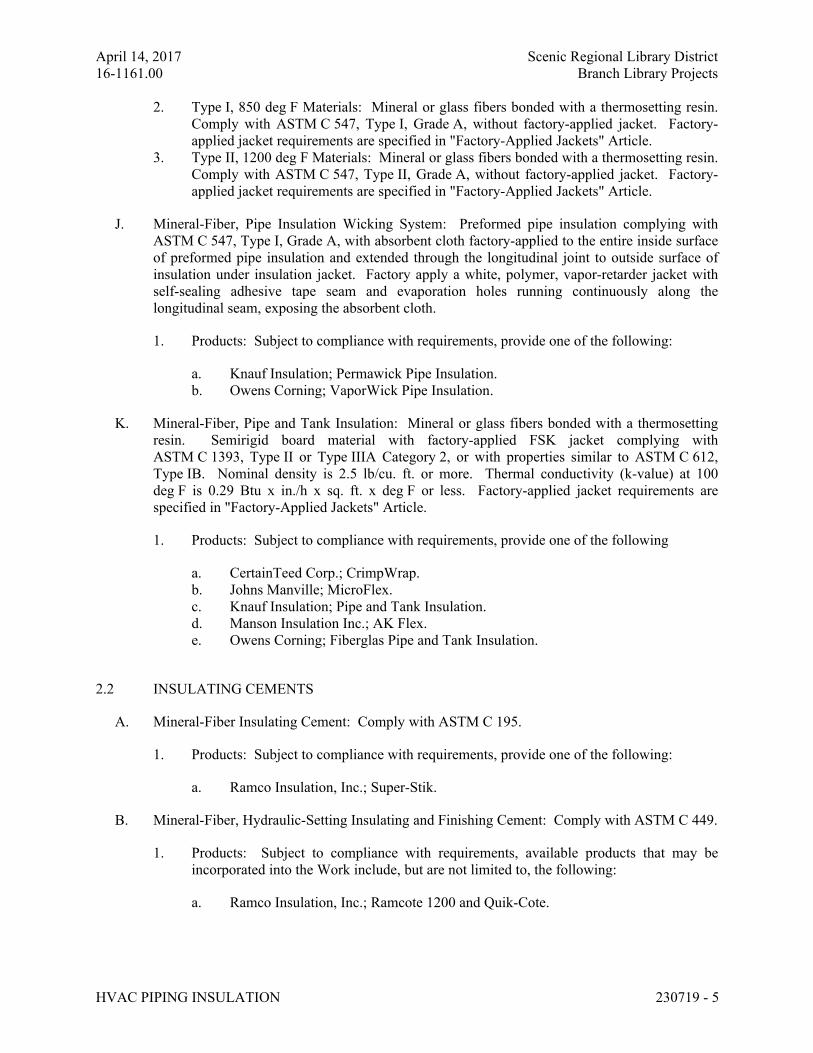
April 14, 2017 Scenic Regional Library District
16-1161.00 Branch Library Projects
HVAC PIPING INSULATION 230719 - 5
2. Type I, 850 deg F Materials: Mineral or glass fibers bonded with a thermosetting resin.
Comply with ASTM C 547, Type I, Grade A, without factory-applied jacket. Factory-
applied jacket requirements are specified in "Factory-Applied Jackets" Article.
3. Type II, 1200 deg F Materials: Mineral or glass fibers bonded with a thermosetting resin.
Comply with ASTM C 547, Type II, Grade A, without factory-applied jacket. Factory-
applied jacket requirements are specified in "Factory-Applied Jackets" Article.
J. Mineral-Fiber, Pipe Insulation Wicking System: Preformed pipe insulation complying with
ASTM C 547, Type I, Grade A, with absorbent cloth factory-applied to the entire inside surface
of preformed pipe insulation and extended through the longitudinal joint to outside surface of
insulation under insulation jacket. Factory apply a white, polymer, vapor-retarder jacket with
self-sealing adhesive tape seam and evaporation holes running continuously along the
longitudinal seam, exposing the absorbent cloth.
1. Products: Subject to compliance with requirements, provide one of the following:
a. Knauf Insulation; Permawick Pipe Insulation.
b. Owens Corning; VaporWick Pipe Insulation.
K. Mineral-Fiber, Pipe and Tank Insulation: Mineral or glass fibers bonded with a thermosetting
resin. Semirigid board material with factory-applied FSK jacket complying with
ASTM C 1393, Type II or Type IIIA Category 2, or with properties similar to ASTM C 612,
Type IB. Nominal density is 2.5 lb/cu. ft. or more. Thermal conductivity (k-value) at 100
deg F is 0.29 Btu x in./h x sq. ft. x deg F or less. Factory-applied jacket requirements are
specified in "Factory-Applied Jackets" Article.
1. Products: Subject to compliance with requirements, provide one of the following
a. CertainTeed Corp.; CrimpWrap.
b. Johns Manville; MicroFlex.
c. Knauf Insulation; Pipe and Tank Insulation.
d. Manson Insulation Inc.; AK Flex.
e. Owens Corning; Fiberglas Pipe and Tank Insulation.
2.2 INSULATING CEMENTS
A. Mineral-Fiber Insulating Cement: Comply with ASTM C 195.
1. Products: Subject to compliance with requirements, provide one of the following:
a. Ramco Insulation, Inc.; Super-Stik.
B. Mineral-Fiber, Hydraulic-Setting Insulating and Finishing Cement: Comply with ASTM C 449.
1. Products: Subject to compliance with requirements, available products that may be
incorporated into the Work include, but are not limited to, the following:
a. Ramco Insulation, Inc.; Ramcote 1200 and Quik-Cote.
April 14, 2017 Scenic Regional Library District
16-1161.00 Branch Library Projects
HVAC PIPING INSULATION 230719 - 6
2.3 ADHESIVES
A. Materials shall be compatible with insulation materials, jackets, and substrates and for bonding
insulation to itself and to surfaces to be insulated unless otherwise indicated.
B. Calcium Silicate Adhesive: Fibrous, sodium-silicate-based adhesive with a service temperature
range of 50 to 800 deg F.
1. Products: Subject to compliance with requirements, provide one of the following:
a. Childers Brand, Specialty Construction Brands, Inc., a business of H. B. Fuller
Company; CP-97.
b. Eagle Bridges - Marathon Industries; 290.
c. Foster Brand, Specialty Construction Brands, Inc., a business of H. B. Fuller
Company; 81-27.
d. Mon-Eco Industries, Inc.; 22-30.
e. Vimasco Corporation; 760.
2. For indoor applications, adhesive shall have a VOC content of 80 g/L or less when
calculated according to 40 CFR 59, Subpart D (EPA Method 24).
3. Adhesive shall comply with the testing and product requirements of the California
Department of Health Services' "Standard Practice for the Testing of Volatile Organic
Emissions from Various Sources Using Small-Scale Environmental Chambers."
C. Cellular-Glass Adhesive: Two-component, thermosetting urethane adhesive containing no
flammable solvents, with a service temperature range of minus 100 to plus 200 deg F.
1. Products: Subject to compliance with requirements, provide one of the following:
a. Foster Brand, Specialty Construction Brands, Inc., a business of H. B. Fuller
Company; 81-84.
2. For indoor applications, adhesive shall have a VOC content of 50 g/L or less when
calculated according to 40 CFR 59, Subpart D (EPA Method 24).
3. Adhesive shall comply with the testing and product requirements of the California
Department of Health Services' "Standard Practice for the Testing of Volatile Organic
Emissions from Various Sources Using Small-Scale Environmental Chambers."
D. Flexible Elastomeric and Polyolefin Adhesive: Comply with MIL-A-24179A, Type II, Class I.
1. Products: Subject to compliance with requirements, provide one of the following:
a. Aeroflex USA, Inc.; Aeroseal.
b. Armacell LLC; Armaflex 520 Adhesive.
c. Foster Brand, Specialty Construction Brands, Inc., a business of H. B. Fuller
Company; 85-75.
d. K-Flex USA; R-373 Contact Adhesive.
2. For indoor applications, adhesive shall have a VOC content of 50 g/L or less when
calculated according to 40 CFR 59, Subpart D (EPA Method 24).
April 14, 2017 Scenic Regional Library District
16-1161.00 Branch Library Projects
HVAC PIPING INSULATION 230719 - 7
3. Adhesive shall comply with the testing and product requirements of the California
Department of Health Services' "Standard Practice for the Testing of Volatile Organic
Emissions from Various Sources Using Small-Scale Environmental Chambers."
E. Mineral-Fiber Adhesive: Comply with MIL-A-3316C, Class 2, Grade A.
1. Products: Subject to compliance with requirements, provide one of the following:
a. Childers Brand, Specialty Construction Brands, Inc., a business of H. B. Fuller
Company; CP-127.
b. Eagle Bridges - Marathon Industries; 225.
c. Foster Brand, Specialty Construction Brands, Inc., a business of H. B. Fuller
Company; 85-60/85-70.
d. Mon-Eco Industries, Inc.; 22-25.
2. For indoor applications, adhesive shall have a VOC content of 80 g/L or less when
calculated according to 40 CFR 59, Subpart D (EPA Method 24).
3. Adhesive shall comply with the testing and product requirements of the California
Department of Health Services' "Standard Practice for the Testing of Volatile Organic
Emissions from Various Sources Using Small-Scale Environmental Chambers."
2.4 MASTICS
A. Materials shall be compatible with insulation materials, jackets, and substrates; comply with
MIL-PRF-19565C, Type II.
1. For indoor applications, use mastics that have a VOC content of 50 g/L or less when
calculated according to 40 CFR 59, Subpart D (EPA Method 24).
B. Vapor-Barrier Mastic: Water based; suitable for indoor use on below-ambient services.
1. Products: Subject to compliance with requirements, provide one of the following
a. Foster Brand, Specialty Construction Brands, Inc., a business of H. B. Fuller
Company; 30-80/30-90.
b. Vimasco Corporation; 749.
2. Water-Vapor Permeance: ASTM E 96/E 96M, Procedure B, 0.013 perm at 43-mil dry
film thickness.
3. Service Temperature Range: Minus 20 to plus 180 deg F.
4. Solids Content: ASTM D 1644, 58 percent by volume and 70 percent by weight.
5. Color: White.
C. Vapor-Barrier Mastic: Solvent based; suitable for indoor use on below-ambient services.
1. Products: Subject to compliance with requirements, provide one of the following:
a. Childers Brand, Specialty Construction Brands, Inc., a business of H. B. Fuller
Company; CP-30.
b. Eagle Bridges - Marathon Industries; 501.
April 14, 2017 Scenic Regional Library District
16-1161.00 Branch Library Projects
HVAC PIPING INSULATION 230719 - 8
c. Foster Brand, Specialty Construction Brands, Inc., a business of H. B. Fuller
Company; 30-35.
d. Mon-Eco Industries, Inc.; 55-10.
2. Water-Vapor Permeance: ASTM F 1249, 0.05 perm at 35-mil dry film thickness.
3. Service Temperature Range: 0 to 180 deg F.
4. Solids Content: ASTM D 1644, 44 percent by volume and 62 percent by weight.
5. Color: White.
D. Vapor-Barrier Mastic: Solvent based; suitable for outdoor use on below-ambient services.
1. Products: Subject to compliance with requirements, provide one of the following:
a. Childers Brand, Specialty Construction Brands, Inc., a business of H. B. Fuller
Company; Encacel.
b. Eagle Bridges - Marathon Industries; 570.
c. Foster Brand, Specialty Construction Brands, Inc., a business of H. B. Fuller
Company; 60-95/60-96.
2. Water-Vapor Permeance: ASTM F 1249, 0.05 perm at 30-mil dry film thickness.
3. Service Temperature Range: Minus 50 to plus 220 deg F.
4. Solids Content: ASTM D 1644, 33 percent by volume and 46 percent by weight.
5. Color: White.
E. Breather Mastic: Water based; suitable for indoor and outdoor use on above-ambient services.
1. Products: Subject to compliance with requirements, provide one of the following:
a. Childers Brand, Specialty Construction Brands, Inc., a business of H. B. Fuller
Company; CP-10.
b. Eagle Bridges - Marathon Industries; 550.
c. Foster Brand, Specialty Construction Brands, Inc., a business of H. B. Fuller
Company; 46-50.
d. Mon-Eco Industries, Inc.; 55-50.
e. Vimasco Corporation; WC-1/WC-5.
2. Water-Vapor Permeance: ASTM F 1249, 1.8 perms at 0.0625-inch dry film thickness.
3. Service Temperature Range: Minus 20 to plus 180 deg F. Solids Content: 60 percent by
volume and 66 percent by weight.
4. Color: White.
2.5 SEALANTS
A. Joint Sealants:
1. Joint Sealants for Cellular-Glass Products: Subject to compliance with requirements,
provide one of the following:
a. Childers Brand, Specialty Construction Brands, Inc., a business of H. B. Fuller
Company; CP-76.
April 14, 2017 Scenic Regional Library District
16-1161.00 Branch Library Projects
HVAC PIPING INSULATION 230719 - 9
b. Eagle Bridges - Marathon Industries; 405.
c. Foster Brand, Specialty Construction Brands, Inc., a business of H. B. Fuller
Company; 30-45.
d. Mon-Eco Industries, Inc.; 44-05.
e. Pittsburgh Corning Corporation; Pittseal 444.
2. Joint Sealants for Polystyrene Products: Subject to compliance with requirements,
provide one of the following:
a. Childers Brand, Specialty Construction Brands, Inc., a business of H. B. Fuller
Company; CP-70.
b. Eagle Bridges - Marathon Industries; 405.
c. Foster Brand, Specialty Construction Brands, Inc., a business of H. B. Fuller
Company; 30-45.
d. Mon-Eco Industries, Inc.; 44-05.
3. Materials shall be compatible with insulation materials, jackets, and substrates.
4. Permanently flexible, elastomeric sealant.
5. Service Temperature Range: Minus 100 to plus 300 deg F. Color: White or gray.
6. For indoor applications, sealants shall have a VOC content of 420 g/L or less when
calculated according to 40 CFR 59, Subpart D (EPA Method 24).
7. Sealants shall comply with the testing and product requirements of the California
Department of Health Services' "Standard Practice for the Testing of Volatile Organic
Emissions from Various Sources Using Small-Scale Environmental Chambers."
B. FSK and Metal Jacket Flashing Sealants:
1. Products: Subject to compliance with requirements, provide one of the following:
a. Childers Brand, Specialty Construction Brands, Inc., a business of H. B. Fuller
Company; CP-76.
b. Eagle Bridges - Marathon Industries; 405.
c. Foster Brand, Specialty Construction Brands, Inc., a business of H. B. Fuller
Company; 95-44.
d. Mon-Eco Industries, Inc.; 44-05.
2. Materials shall be compatible with insulation materials, jackets, and substrates.
3. Fire- and water-resistant, flexible, elastomeric sealant.
4. Service Temperature Range: Minus 40 to plus 250 deg F.
5. Color: Aluminum.
6. For indoor applications, sealants shall have a VOC content of 420 g/L or less when
calculated according to 40 CFR 59, Subpart D (EPA Method 24).
7. Sealants shall comply with the testing and product requirements of the California
Department of Health Services' "Standard Practice for the Testing of Volatile Organic
Emissions from Various Sources Using Small-Scale Environmental Chambers."
2.6 FIELD-APPLIED JACKETS
A. Field-applied jackets shall comply with ASTM C 921, Type I, unless otherwise indicated.
April 14, 2017 Scenic Regional Library District
16-1161.00 Branch Library Projects
HVAC PIPING INSULATION 230719 - 10
B. FSK Jacket: Aluminum-foil-face, fiberglass-reinforced scrim with kraft-paper backing.
C. Metal Jacket:
1. Products: Subject to compliance with requirements, provide one of the following
a. Childers Brand, Specialty Construction Brands, Inc., a business of H. B. Fuller
Company; Metal Jacketing Systems.
b. ITW Insulation Systems; Aluminum and Stainless Steel Jacketing.
c. RPR Products, Inc.; Insul-Mate.
d. <Insert manufacturer's name; product name or designation>.
2. Aluminum Jacket: Comply with ASTM B 209, Alloy 3003, 3005, 3105, or 5005,
Temper H-14.
a. Factory cut and rolled to size.
b. Finish and thickness are indicated in field-applied jacket schedules.
c. Moisture Barrier for Indoor Applications: 2.5-mil thick polysurlyn.
d. Moisture Barrier for Outdoor Applications: 2.5-mil thick polysurlyn.
e. Factory-Fabricated Fitting Covers:
1) Same material, finish, and thickness as jacket.
2) Preformed 2-piece or gore, 45- and 90-degree, short- and long-radius
elbows.
3) Tee covers.
4) Flange and union covers.
5) End caps.
6) Beveled collars.
7) Valve covers.
8) Field fabricate fitting covers only if factory-fabricated fitting covers are not
available.
D. Underground Direct-Buried Jacket: 125-mil thick vapor barrier and waterproofing membrane
consisting of a rubberized bituminous resin reinforced with a woven-glass fiber or polyester
scrim and laminated aluminum foil.
1. Products: Subject to compliance with requirements, provide one of the following:
a. Pittsburgh Corning Corporation; Pittwrap.
b. Polyguard Products, Inc.; Insulrap No Torch 125.
E. Self-Adhesive Outdoor Jacket: 60-mil thick, laminated vapor barrier and waterproofing
membrane for installation over insulation located aboveground outdoors; consisting of a
rubberized bituminous resin on a crosslaminated polyethylene film covered with aluminum-foil
facing.
1. Products: Subject to compliance with requirements, provide one of the following:
a. Polyguard Products, Inc.; Alumaguard 60.
April 14, 2017 Scenic Regional Library District
16-1161.00 Branch Library Projects
HVAC PIPING INSULATION 230719 - 11
2.7 TAPES
A. ASJ Tape: White vapor-retarder tape matching factory-applied jacket with acrylic adhesive,
complying with ASTM C 1136.
1. Products: Subject to compliance with requirements, provide one of the following:
a. ABI, Ideal Tape Division; 428 AWF ASJ.
b. Avery Dennison Corporation, Specialty Tapes Division; Fasson 0836.
c. Compac Corporation; 104 and 105.
d. Venture Tape; 1540 CW Plus, 1542 CW Plus, and 1542 CW Plus/SQ.
2. Width: 3 inches.
3. Thickness: 11.5 mils.
4. Adhesion: 90 ounces force/inch in width.
5. Elongation: 2 percent.
6. Tensile Strength: 40 lbf/inch in width.
7. ASJ Tape Disks and Squares: Precut disks or squares of ASJ tape.
B. FSK Tape: Foil-face, vapor-retarder tape matching factory-applied jacket with acrylic adhesive;
complying with ASTM C 1136.
1. Products: Subject to compliance with requirements, provide one of the following:
a. ABI, Ideal Tape Division; 491 AWF FSK.
b. Avery Dennison Corporation, Specialty Tapes Division; Fasson 0827.
c. Compac Corporation; 110 and 111.
d. Venture Tape; 1525 CW NT, 1528 CW, and 1528 CW/SQ.
2. Width: 3 inches.
3. Thickness: 6.5 mils.
4. Adhesion: 90 ounces force/inch in width.
5. Elongation: 2 percent.
6. Tensile Strength: 40 lbf/inch in width.
7. FSK Tape Disks and Squares: Precut disks or squares of FSK tape.
C. Aluminum-Foil Tape: Vapor-retarder tape with acrylic adhesive.
1. Products: Subject to compliance with requirements, provide one of the following:
a. ABI, Ideal Tape Division; 488 AWF.
b. Avery Dennison Corporation, Specialty Tapes Division; Fasson 0800.
c. Compac Corporation; 120.
d. Venture Tape; 3520 CW.
2. Width: 2 inches.
3. Thickness: 3.7 mils.
4. Adhesion: 100 ounces force/inch in width.
5. Elongation: 5 percent.
6. Tensile Strength: 34 lbf/inch in width.
April 14, 2017 Scenic Regional Library District
16-1161.00 Branch Library Projects
HVAC PIPING INSULATION 230719 - 12
2.8 SECUREMENTS
A. Bands:
1. Products: Subject to compliance with requirements, provide one of the following:
a. ITW Insulation Systems; Gerrard Strapping and Seals.
b. RPR Products, Inc.; Insul-Mate Strapping, Seals, and Springs.
2. Stainless Steel: ASTM A 167 or ASTM A 240/A 240M, Type 304 or Type 316; 0.015
inch thick, 3/4 inch wide with wing seal or closed seal.
3. Aluminum: ASTM B 209, Alloy 3003, 3005, 3105, or 5005; Temper H-14, 0.020 inch
thick, 3/4 inch wide with wing seal or closed seal.
4. Springs: Twin spring set constructed of stainless steel with ends flat and slotted to accept
metal bands. Spring size determined by manufacturer for application.
B. Staples: Outward-clinching insulation staples, nominal 3/4-inch wide, stainless steel or Monel.
C. Wire: 0.080-inch nickel-copper alloy.
1. Manufacturers: Subject to compliance with requirements, manufacturers offering
products that may be incorporated into the Work include, but are not limited to, the
following:
a. C & F Wire.
PART 3 - EXECUTION
3.1 EXAMINATION
A. Examine substrates and conditions for compliance with requirements for installation tolerances
and other conditions affecting performance of insulation application.
1. Verify that systems to be insulated have been tested and are free of defects.
2. Verify that surfaces to be insulated are clean and dry.
3. Proceed with installation only after unsatisfactory conditions have been corrected.
3.2 PREPARATION
A. Surface Preparation: Clean and dry surfaces to receive insulation. Remove materials that will
adversely affect insulation application.
B. Surface Preparation: Clean and prepare surfaces to be insulated. Before insulating, apply a
corrosion coating to insulated surfaces as follows:
1. Stainless Steel: Coat 300 series stainless steel with an epoxy primer 5 mils thick and an
epoxy finish 5 mils thick if operating in a temperature range between 140 and 300 deg F.
Consult coating manufacturer for appropriate coating materials and application methods
for operating temperature range.
April 14, 2017 Scenic Regional Library District
16-1161.00 Branch Library Projects
HVAC PIPING INSULATION 230719 - 13
2. Carbon Steel: Coat carbon steel operating at a service temperature between 32 and 300
deg F with an epoxy coating. Consult coating manufacturer for appropriate coating
materials and application methods for operating temperature range.
C. Coordinate insulation installation with the trade installing heat tracing. Comply with
requirements for heat tracing that apply to insulation.
D. Mix insulating cements with clean potable water; if insulating cements are to be in contact with
stainless-steel surfaces, use demineralized water.
3.3 GENERAL INSTALLATION REQUIREMENTS
A. Install insulation materials, accessories, and finishes with smooth, straight, and even surfaces;
free of voids throughout the length of piping including fittings, valves, and specialties.
B. Install insulation materials, forms, vapor barriers or retarders, jackets, and thicknesses required
for each item of pipe system as specified in insulation system schedules.
C. Install accessories compatible with insulation materials and suitable for the service. Install
accessories that do not corrode, soften, or otherwise attack insulation or jacket in either wet or
dry state.
D. Install insulation with longitudinal seams at top and bottom of horizontal runs.
E. Install multiple layers of insulation with longitudinal and end seams staggered.
F. Do not weld brackets, clips, or other attachment devices to piping, fittings, and specialties.
G. Keep insulation materials dry during application and finishing.
H. Install insulation with tight longitudinal seams and end joints. Bond seams and joints with
adhesive recommended by insulation material manufacturer.
I. Install insulation with least number of joints practical.
J. Where vapor barrier is indicated, seal joints, seams, and penetrations in insulation at hangers,
supports, anchors, and other projections with vapor-barrier mastic.
1. Install insulation continuously through hangers and around anchor attachments.
2. For insulation application where vapor barriers are indicated, extend insulation on anchor
legs from point of attachment to supported item to point of attachment to structure. Taper
and seal ends at attachment to structure with vapor-barrier mastic.
3. Install insert materials and install insulation to tightly join the insert. Seal insulation to
insulation inserts with adhesive or sealing compound recommended by insulation
material manufacturer.
4. Cover inserts with jacket material matching adjacent pipe insulation. Install shields over
jacket, arranged to protect jacket from tear or puncture by hanger, support, and shield.
K. Apply adhesives, mastics, and sealants at manufacturer's recommended coverage rate and wet
and dry film thicknesses.
April 14, 2017 Scenic Regional Library District
16-1161.00 Branch Library Projects
HVAC PIPING INSULATION 230719 - 14
L. Install insulation with factory-applied jackets as follows:
1. Draw jacket tight and smooth.
2. Cover circumferential joints with 3-inch wide strips, of same material as insulation
jacket. Secure strips with adhesive and outward clinching staples along both edges of
strip, spaced 4 inches o.c.
3. Overlap jacket longitudinal seams at least 1-1/2 inches. Install insulation with
longitudinal seams at bottom of pipe. Clean and dry surface to receive self-sealing lap.
Staple laps with outward clinching staples along edge at 2 inches o.c.
a. For below-ambient services, apply vapor-barrier mastic over staples.
4. Cover joints and seams with tape, according to insulation material manufacturer's written
instructions, to maintain vapor seal.
5. Where vapor barriers are indicated, apply vapor-barrier mastic on seams and joints and at
ends adjacent to pipe flanges and fittings.
M. Cut insulation in a manner to avoid compressing insulation more than 75 percent of its nominal
thickness.
N. Finish installation with systems at operating conditions. Repair joint separations and cracking
due to thermal movement.
O. Repair damaged insulation facings by applying same facing material over damaged areas.
Extend patches at least 4 inches (100 mm) beyond damaged areas. Adhere, staple, and seal
patches similar to butt joints.
P. For above-ambient services, do not install insulation to the following:
1. Vibration-control devices.
2. Testing agency labels and stamps.
3. Nameplates and data plates.
4. Manholes.
5. Handholes.
6. Cleanouts.
3.4 PENETRATIONS
A. Insulation Installation at Roof Penetrations: Install insulation continuously through roof
penetrations.
1. Seal penetrations with flashing sealant.
2. For applications requiring only indoor insulation, terminate insulation above roof surface
and seal with joint sealant. For applications requiring indoor and outdoor insulation,
install insulation for outdoor applications tightly joined to indoor insulation ends. Seal
joint with joint sealant.
3. Extend jacket of outdoor insulation outside roof flashing at least 2 inches below top of
roof flashing.
4. Seal jacket to roof flashing with flashing sealant.
April 14, 2017 Scenic Regional Library District
16-1161.00 Branch Library Projects
HVAC PIPING INSULATION 230719 - 15
B. Insulation Installation at Aboveground Exterior Wall Penetrations: Install insulation
continuously through wall penetrations.
1. Seal penetrations with flashing sealant.
2. For applications requiring only indoor insulation, terminate insulation inside wall surface
and seal with joint sealant. For applications requiring indoor and outdoor insulation,
install insulation for outdoor applications tightly joined to indoor insulation ends. Seal
joint with joint sealant.
3. Extend jacket of outdoor insulation outside wall flashing and overlap wall flashing at
least 2 inches.
4. Seal jacket to wall flashing with flashing sealant.
C. Insulation Installation at Interior Wall and Partition Penetrations (That Are Not Fire Rated):
Install insulation continuously through walls and partitions.
D. Insulation Installation at Floor Penetrations:
1. Pipe: Install insulation continuously through floor penetrations.
2. Seal penetrations through fire-rated assemblies. Comply with requirements in
Section 078413 "Penetration Firestopping."
3.5 GENERAL PIPE INSULATION INSTALLATION
A. Requirements in this article generally apply to all insulation materials except where more
specific requirements are specified in various pipe insulation material installation articles.
B. Insulation Installation on Fittings, Valves, Strainers, Flanges, and Unions:
1. Install insulation over fittings, valves, strainers, flanges, unions, and other specialties with
continuous thermal and vapor-retarder integrity unless otherwise indicated.
2. Insulate pipe elbows using preformed fitting insulation or mitered fittings made from
same material and density as adjacent pipe insulation. Each piece shall be butted tightly
against adjoining piece and bonded with adhesive. Fill joints, seams, voids, and irregular
surfaces with insulating cement finished to a smooth, hard, and uniform contour that is
uniform with adjoining pipe insulation.
3. Insulate tee fittings with preformed fitting insulation or sectional pipe insulation of same
material and thickness as used for adjacent pipe. Cut sectional pipe insulation to fit. Butt
each section closely to the next and hold in place with tie wire. Bond pieces with
adhesive.
4. Insulate valves using preformed fitting insulation or sectional pipe insulation of same
material, density, and thickness as used for adjacent pipe. Overlap adjoining pipe
insulation by not less than two times the thickness of pipe insulation, or one pipe
diameter, whichever is thicker. For valves, insulate up to and including the bonnets,
valve stuffing-box studs, bolts, and nuts. Fill joints, seams, and irregular surfaces with
insulating cement.
5. Insulate strainers using preformed fitting insulation or sectional pipe insulation of same
material, density, and thickness as used for adjacent pipe. Overlap adjoining pipe
insulation by not less than two times the thickness of pipe insulation, or one pipe
diameter, whichever is thicker. Fill joints, seams, and irregular surfaces with insulating
cement. Insulate strainers so strainer basket flange or plug can be easily removed and
April 14, 2017 Scenic Regional Library District
16-1161.00 Branch Library Projects
HVAC PIPING INSULATION 230719 - 16
replaced without damaging the insulation and jacket. Provide a removable reusable
insulation cover. For below-ambient services, provide a design that maintains vapor
barrier.
6. Insulate flanges and unions using a section of oversized preformed pipe insulation.
Overlap adjoining pipe insulation by not less than two times the thickness of pipe
insulation, or one pipe diameter, whichever is thicker.
7. Cover segmented insulated surfaces with a layer of finishing cement and coat with a
mastic. Install vapor-barrier mastic for below-ambient services and a breather mastic for
above-ambient services. Reinforce the mastic with fabric-reinforcing mesh. Trowel the
mastic to a smooth and well-shaped contour.
8. For services not specified to receive a field-applied jacket except for flexible elastomeric
and polyolefin, install fitted PVC cover over elbows, tees, strainers, valves, flanges, and
unions. Terminate ends with PVC end caps. Tape PVC covers to adjoining insulation
facing using PVC tape.
9. Stencil or label the outside insulation jacket of each union with the word "union." Match
size and color of pipe labels.
C. Insulate instrument connections for thermometers, pressure gages, pressure temperature taps,
test connections, flow meters, sensors, switches, and transmitters on insulated pipes. Shape
insulation at these connections by tapering it to and around the connection with insulating
cement and finish with finishing cement, mastic, and flashing sealant.
D. Install removable insulation covers at locations indicated. Installation shall conform to the
following:
1. Make removable flange and union insulation from sectional pipe insulation of same
thickness as that on adjoining pipe. Install same insulation jacket as adjoining pipe
insulation.
2. When flange and union covers are made from sectional pipe insulation, extend insulation
from flanges or union long at least two times the insulation thickness over adjacent pipe
insulation on each side of flange or union. Secure flange cover in place with stainless-
steel or aluminum bands. Select band material compatible with insulation and jacket.
3. Construct removable valve insulation covers in same manner as for flanges, except divide
the two-part section on the vertical center line of valve body.
4. When covers are made from block insulation, make two halves, each consisting of
mitered blocks wired to stainless-steel fabric. Secure this wire frame, with its attached
insulation, to flanges with tie wire. Extend insulation at least 2 inches over adjacent pipe
insulation on each side of valve. Fill space between flange or union cover and pipe
insulation with insulating cement. Finish cover assembly with insulating cement applied
in two coats. After first coat is dry, apply and trowel second coat to a smooth finish.
3.6 INSTALLATION OF CELLULAR-GLASS INSULATION
A. Insulation Installation on Straight Pipes and Tubes:
1. Secure each layer of insulation to pipe with wire or bands and tighten bands without
deforming insulation materials.
2. Where vapor barriers are indicated, seal longitudinal seams, end joints, and protrusions
with vapor-barrier mastic and joint sealant.
April 14, 2017 Scenic Regional Library District
16-1161.00 Branch Library Projects
HVAC PIPING INSULATION 230719 - 17
3. For insulation with factory-applied jackets on above-ambient services, secure laps with
outward-clinched staples at 6 inches o.c.
4. For insulation with factory-applied jackets on below-ambient services, do not staple
longitudinal tabs. Instead, secure tabs with additional adhesive as recommended by
insulation material manufacturer and seal with vapor-barrier mastic and flashing sealant.
B. Insulation Installation on Pipe Flanges:
1. Install preformed pipe insulation to outer diameter of pipe flange.
2. Make width of insulation section same as overall width of flange and bolts, plus twice the
thickness of pipe insulation.
3. Fill voids between inner circumference of flange insulation and outer circumference of
adjacent straight pipe segments with cut sections of cellular-glass block insulation of
same thickness as pipe insulation.
4. Install jacket material with manufacturer's recommended adhesive, overlap seams at least
1 inch, and seal joints with flashing sealant.
C. Insulation Installation on Pipe Fittings and Elbows:
1. Install preformed sections of same material as straight segments of pipe insulation when
available. Secure according to manufacturer's written instructions.
2. When preformed sections of insulation are not available, install mitered sections of
cellular-glass insulation. Secure insulation materials with wire or bands.
D. Insulation Installation on Valves and Pipe Specialties:
1. Install preformed sections of cellular-glass insulation to valve body.
2. Arrange insulation to permit access to packing and to allow valve operation without
disturbing insulation.
3. Install insulation to flanges as specified for flange insulation application.
3.7 INSTALLATION OF FLEXIBLE ELASTOMERIC INSULATION
A. Seal longitudinal seams and end joints with manufacturer's recommended adhesive to eliminate
openings in insulation that allow passage of air to surface being insulated.
B. Insulation Installation on Pipe Flanges:
1. Install pipe insulation to outer diameter of pipe flange.
2. Make width of insulation section same as overall width of flange and bolts, plus twice the
thickness of pipe insulation.
3. Fill voids between inner circumference of flange insulation and outer circumference of
adjacent straight pipe segments with cut sections of sheet insulation of same thickness as
pipe insulation.
4. Secure insulation to flanges and seal seams with manufacturer's recommended adhesive
to eliminate openings in insulation that allow passage of air to surface being insulated.
C. Insulation Installation on Pipe Fittings and Elbows:
1. Install mitered sections of pipe insulation.
April 14, 2017 Scenic Regional Library District
16-1161.00 Branch Library Projects
HVAC PIPING INSULATION 230719 - 18
2. Secure insulation materials and seal seams with manufacturer's recommended adhesive to
eliminate openings in insulation that allow passage of air to surface being insulated.
D. Insulation Installation on Valves and Pipe Specialties:
1. Install preformed valve covers manufactured of same material as pipe insulation when
available.
2. When preformed valve covers are not available, install cut sections of pipe and sheet
insulation to valve body. Arrange insulation to permit access to packing and to allow
valve operation without disturbing insulation.
3. Install insulation to flanges as specified for flange insulation application.
4. Secure insulation to valves and specialties and seal seams with manufacturer's
recommended adhesive to eliminate openings in insulation that allow passage of air to
surface being insulated.
3.8 INSTALLATION OF MINERAL-FIBER INSULATION
A. Insulation Installation on Straight Pipes and Tubes:
1. Secure each layer of preformed pipe insulation to pipe with wire or bands and tighten
bands without deforming insulation materials.
2. Where vapor barriers are indicated, seal longitudinal seams, end joints, and protrusions
with vapor-barrier mastic and joint sealant.
3. For insulation with factory-applied jackets on above-ambient surfaces, secure laps with
outward-clinched staples at 6 inches o.c.
4. For insulation with factory-applied jackets on below-ambient surfaces, do not staple
longitudinal tabs. Instead, secure tabs with additional adhesive as recommended by
insulation material manufacturer and seal with vapor-barrier mastic and flashing sealant.
B. Insulation Installation on Pipe Flanges:
1. Install preformed pipe insulation to outer diameter of pipe flange.
2. Make width of insulation section same as overall width of flange and bolts, plus twice the
thickness of pipe insulation.
3. Fill voids between inner circumference of flange insulation and outer circumference of
adjacent straight pipe segments with mineral-fiber blanket insulation.
4. Install jacket material with manufacturer's recommended adhesive, overlap seams at least
1 inch, and seal joints with flashing sealant.
C. Insulation Installation on Pipe Fittings and Elbows:
1. Install preformed sections of same material as straight segments of pipe insulation when
available.
2. When preformed insulation elbows and fittings are not available, install mitered sections
of pipe insulation, to a thickness equal to adjoining pipe insulation. Secure insulation
materials with wire or bands.
D. Insulation Installation on Valves and Pipe Specialties:
April 14, 2017 Scenic Regional Library District
16-1161.00 Branch Library Projects
HVAC PIPING INSULATION 230719 - 19
1. Install preformed sections of same material as straight segments of pipe insulation when
available.
2. When preformed sections are not available, install mitered sections of pipe insulation to
valve body.
3. Arrange insulation to permit access to packing and to allow valve operation without
disturbing insulation.
4. Install insulation to flanges as specified for flange insulation application.
3.9 FIELD-APPLIED JACKET INSTALLATION
A. Where glass-cloth jackets are indicated, install directly over bare insulation or insulation with
factory-applied jackets.
1. Draw jacket smooth and tight to surface with 2-inch overlap at seams and joints.
2. Embed glass cloth between two 0.062-inch thick coats of lagging adhesive.
3. Completely encapsulate insulation with coating, leaving no exposed insulation.
B. Where FSK jackets are indicated, install as follows:
1. Draw jacket material smooth and tight.
2. Install lap or joint strips with same material as jacket.
3. Secure jacket to insulation with manufacturer's recommended adhesive.
4. Install jacket with 1-1/2-inch laps at longitudinal seams and 3-inch wide joint strips at
end joints.
5. Seal openings, punctures, and breaks in vapor-retarder jackets and exposed insulation
with vapor-barrier mastic.
C. Where PVC jackets are indicated, install with 1-inch overlap at longitudinal seams and end
joints; for horizontal applications. Seal with manufacturer's recommended adhesive.
1. Apply two continuous beads of adhesive to seams and joints, one bead under lap and the
finish bead along seam and joint edge.
D. Where metal jackets are indicated, install with 2-inch overlap at longitudinal seams and end
joints. Overlap longitudinal seams arranged to shed water. Seal end joints with weatherproof
sealant recommended by insulation manufacturer. Secure jacket with stainless-steel bands 12
inches o.c. and at end joints.
3.10 FINISHES
A. Pipe Insulation with ASJ, Glass-Cloth, or Other Paintable Jacket Material: Paint jacket with
paint system identified below and as specified in Section 099113 "Exterior Painting" and
Section 099123 "Interior Painting."
1. Flat Acrylic Finish: Two finish coats over a primer that is compatible with jacket
material and finish coat paint. Add fungicidal agent to render fabric mildew proof.
a. Finish Coat Material: Interior, flat, latex-emulsion size.
Comment [DEL1]: Per e-mail from JRB
on 11-17-2014, painting ASJ jacket will
voidUL classification for 25/50 fire/smoke
rating and Knauf’s manufacturer’s
warrenty. 11-14-2014
April 14, 2017 Scenic Regional Library District
16-1161.00 Branch Library Projects
HVAC PIPING INSULATION 230719 - 20
B. Flexible Elastomeric Thermal Insulation: After adhesive has fully cured, apply two coats of
insulation manufacturer's recommended protective coating.
C. Color: Final color as selected by Architect. Vary first and second coats to allow visual
inspection of the completed Work.
D. Do not field paint aluminum or stainless-steel jackets.
3.11 FIELD QUALITY CONTROL
A. Testing Agency: Engage a qualified testing agency to perform tests and inspections.
B. Perform tests and inspections.
C. Tests and Inspections:
1. Inspect pipe, fittings, strainers, and valves, randomly selected by Architect, by removing
field-applied jacket and insulation in layers in reverse order of their installation. Extent
of inspection shall be limited to three locations of straight pipe, three locations of
threaded fittings, three locations of welded fittings, two locations of threaded strainers,
two locations of welded strainers, three locations of threaded valves, and three locations
of flanged valves for each pipe service defined in the "Piping Insulation Schedule,
General" Article.
D. All insulation applications will be considered defective Work if sample inspection reveals
noncompliance with requirements.
3.12 PIPING INSULATION SCHEDULE, GENERAL
A. Acceptable preformed pipe and tubular insulation materials and thicknesses are identified for
each piping system and pipe size range. If more than one material is listed for a piping system,
selection from materials listed is Contractor's option.
B. Items Not Insulated: Unless otherwise indicated, do not install insulation on the following:
1. Drainage piping located in crawl spaces.
2. Underground piping.
3. Chrome-plated pipes and fittings unless there is a potential for personnel injury.
3.13 INDOOR PIPING INSULATION SCHEDULE
A. Condensate and Equipment Drain Water below 60 Deg F:
1. All Pipe Sizes: Insulation shall be one of the following:
a. Cellular Glass: 1-1/2 inches thick.
b. Flexible Elastomeric: 1 inch thick.
c. Mineral-Fiber, Preformed Pipe Insulation, Type I: 1 inch thick.
April 14, 2017 Scenic Regional Library District
16-1161.00 Branch Library Projects
HVAC PIPING INSULATION 230719 - 21
B. Refrigerant Suction and Hot-Gas Piping:
1. All Pipe Sizes: Insulation shall be one of the following:
a. Flexible Elastomeric: 1 inch thick.
b. Mineral-Fiber, Preformed Pipe Insulation, Type I: 1 inch thick.
C. Refrigerant Suction and Hot-Gas Flexible Tubing:
1. All Pipe Sizes: Insulation shall be one of the following:
a. Flexible Elastomeric: 1 inch thick.
3.14 OUTDOOR, ABOVEGROUND PIPING INSULATION SCHEDULE
A. Refrigerant Suction and Hot-Gas Piping:
1. All Pipe Sizes: Insulation shall be one of the following:
a. Cellular Glass: 2 inches thick.
b. Flexible Elastomeric: 2 inches thick.
c. Mineral-Fiber, Preformed Pipe Insulation, Type I: 2 inches thick.
B. Refrigerant Suction and Hot-Gas Flexible Tubing:
1. All Pipe Sizes: Insulation shall be one of the following:
a. Flexible Elastomeric: 2 inches thick.
3.15 INDOOR, FIELD-APPLIED JACKET SCHEDULE
A. Install jacket over insulation material. For insulation with factory-applied jacket, install the
field-applied jacket over the factory-applied jacket.
B. If more than one material is listed, selection from materials listed is Contractor's option.
C. Piping, Concealed:
1. Aluminum, Smooth: 0.024 inch thick.
D. Piping, Exposed:
1. Aluminum, Smooth: 0.024 inch thick.
3.16 OUTDOOR, FIELD-APPLIED JACKET SCHEDULE
A. Install jacket over insulation material. For insulation with factory-applied jacket, install the
field-applied jacket over the factory-applied jacket.
B. If more than one material is listed, selection from materials listed is Contractor's option.
April 14, 2017 Scenic Regional Library District
16-1161.00 Branch Library Projects
HVAC PIPING INSULATION 230719 - 22
C. Piping, Concealed:
1. None.
2. Aluminum, Smooth: 0.024 inch thick.
D. Piping, Exposed:
1. Aluminum, Smooth: .024 inch thick.
END OF SECTION 230719
April 14, 2017 Scenic Regional Library District
16-1161.00 Branch Library Projects
REFRIGERANT PIPING 232300 - 1
SECTION 232300 - REFRIGERANT PIPING
ALL LIBRARIES
PART 1 - GENERAL
1.1 RELATED DOCUMENTS
A. Drawings and general provisions of the Contract, including General and Supplementary
Conditions and Division 01 Specification Sections, apply to this Section.
1.2 SUMMARY
A. This Section includes refrigerant piping used for air-conditioning applications.
1.3 PERFORMANCE REQUIREMENTS
A. Line Test Pressure for Refrigerant R-410A:
1. Suction Lines for Air-Conditioning Applications: 300 psig.
2. Suction Lines for Heat-Pump Applications: 535 psig.
3. Hot-Gas and Liquid Lines: 535 psig.
1.4 ACTION SUBMITTALS
A. Product Data: For each type of valve and refrigerant piping specialty indicated. Include
pressure drop, based on manufacturer's test data, for the following:
1. Thermostatic expansion valves.
2. Solenoid valves.
3. Hot-gas bypass valves.
4. Filter dryers.
5. Strainers.
6. Pressure-regulating valves.
B. Shop Drawings: Show layout of refrigerant piping and specialties, including pipe, tube, and
fitting sizes, flow capacities, valve arrangements and locations, slopes of horizontal runs, oil
traps, double risers, wall and floor penetrations, and equipment connection details. Show
interface and spatial relationships between piping and equipment.
1. Shop Drawing Scale: 1/4 inch equals 1 foot.
2. Refrigerant piping indicated on Drawings is schematic only. Size piping and design
actual piping layout, including oil traps, double risers, specialties, and pipe and tube sizes
to accommodate, as a minimum, equipment provided, elevation difference between
April 14, 2017 Scenic Regional Library District
16-1161.00 Branch Library Projects
REFRIGERANT PIPING 232300 - 2
compressor and evaporator, and length of piping to ensure proper operation and
compliance with warranties of connected equipment.
1.5 INFORMATIONAL SUBMITTALS
A. Welding certificates.
B. Field quality-control test reports.
1.6 CLOSEOUT SUBMITTALS
A. Operation and Maintenance Data: For refrigerant valves and piping specialties to include in
maintenance manuals.
1.7 QUALITY ASSURANCE
A. Welding: Qualify procedures and personnel according to ASME Boiler and Pressure Vessel
Code: Section IX, "Welding and Brazing Qualifications."
B. Comply with ASHRAE 15, "Safety Code for Refrigeration Systems."
C. Comply with ASME B31.5, "Refrigeration Piping and Heat Transfer Components."
1.8 PRODUCT STORAGE AND HANDLING
A. Store piping in a clean and protected area with end caps in place to ensure that piping interior
and exterior are clean when installed.
1.9 COORDINATION
A. Coordinate size and location of roof curbs, equipment supports, and roof penetrations. These
items are specified in Section 077200 "Roof Accessories."
PART 2 - PRODUCTS
2.1 COPPER TUBE AND FITTINGS
A. Copper Tube: ASTM B 88, Type K or L.
B. Wrought-Copper Fittings: ASME B16.22.
C. Wrought-Copper Unions: ASME B16.22.
D. Solder Filler Metals: ASTM B 32. Use 95-5 tin antimony or alloy HB solder to join copper
socket fittings on copper pipe.
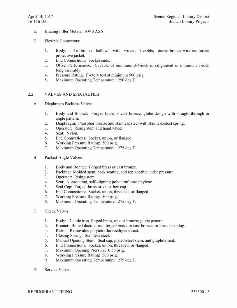
April 14, 2017 Scenic Regional Library District
16-1161.00 Branch Library Projects
REFRIGERANT PIPING 232300 - 3
E. Brazing Filler Metals: AWS A5.8.
F. Flexible Connectors:
1. Body: Tin-bronze bellows with woven, flexible, tinned-bronze-wire-reinforced
protective jacket.
2. End Connections: Socket ends.
3. Offset Performance: Capable of minimum 3/4-inch misalignment in minimum 7-inch
long assembly.
4. Pressure Rating: Factory test at minimum 500 psig.
5. Maximum Operating Temperature: 250 deg F.
2.2 VALVES AND SPECIALTIES
A. Diaphragm Packless Valves:
1. Body and Bonnet: Forged brass or cast bronze; globe design with straight-through or
angle pattern.
2. Diaphragm: Phosphor bronze and stainless steel with stainless-steel spring.
3. Operator: Rising stem and hand wheel.
4. Seat: Nylon.
5. End Connections: Socket, union, or flanged.
6. Working Pressure Rating: 500 psig.
7. Maximum Operating Temperature: 275 deg F.
B. Packed-Angle Valves:
1. Body and Bonnet: Forged brass or cast bronze.
2. Packing: Molded stem, back seating, and replaceable under pressure.
3. Operator: Rising stem.
4. Seat: Nonrotating, self-aligning polytetrafluoroethylene.
5. Seal Cap: Forged-brass or valox hex cap.
6. End Connections: Socket, union, threaded, or flanged.
7. Working Pressure Rating: 500 psig.
8. Maximum Operating Temperature: 275 deg F.
C. Check Valves:
1. Body: Ductile iron, forged brass, or cast bronze; globe pattern.
2. Bonnet: Bolted ductile iron, forged brass, or cast bronze; or brass hex plug.
3. Piston: Removable polytetrafluoroethylene seat.
4. Closing Spring: Stainless steel.
5. Manual Opening Stem: Seal cap, plated-steel stem, and graphite seal.
6. End Connections: Socket, union, threaded, or flanged.
7. Maximum Opening Pressure: 0.50 psig.
8. Working Pressure Rating: 500 psig.
9. Maximum Operating Temperature: 275 deg F.
D. Service Valves:
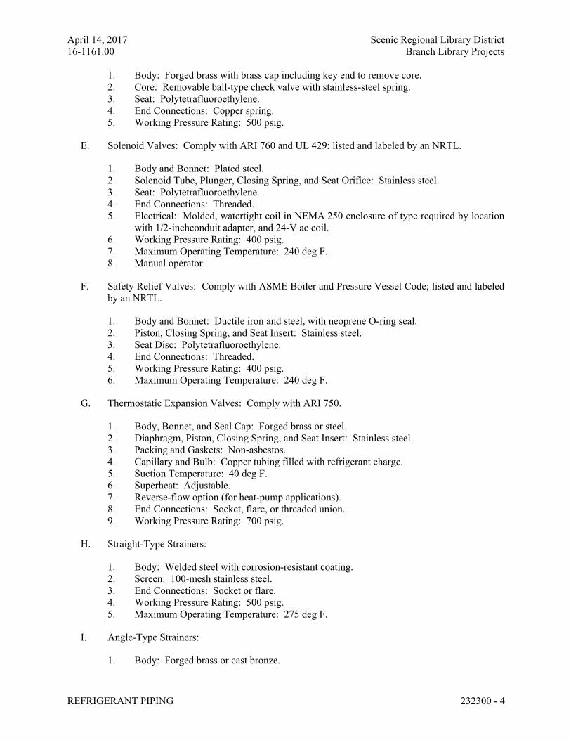
April 14, 2017 Scenic Regional Library District
16-1161.00 Branch Library Projects
REFRIGERANT PIPING 232300 - 4
1. Body: Forged brass with brass cap including key end to remove core.
2. Core: Removable ball-type check valve with stainless-steel spring.
3. Seat: Polytetrafluoroethylene.
4. End Connections: Copper spring.
5. Working Pressure Rating: 500 psig.
E. Solenoid Valves: Comply with ARI 760 and UL 429; listed and labeled by an NRTL.
1. Body and Bonnet: Plated steel.
2. Solenoid Tube, Plunger, Closing Spring, and Seat Orifice: Stainless steel.
3. Seat: Polytetrafluoroethylene.
4. End Connections: Threaded.
5. Electrical: Molded, watertight coil in NEMA 250 enclosure of type required by location
with 1/2-inchconduit adapter, and 24-V ac coil.
6. Working Pressure Rating: 400 psig.
7. Maximum Operating Temperature: 240 deg F.
8. Manual operator.
F. Safety Relief Valves: Comply with ASME Boiler and Pressure Vessel Code; listed and labeled
by an NRTL.
1. Body and Bonnet: Ductile iron and steel, with neoprene O-ring seal.
2. Piston, Closing Spring, and Seat Insert: Stainless steel.
3. Seat Disc: Polytetrafluoroethylene.
4. End Connections: Threaded.
5. Working Pressure Rating: 400 psig.
6. Maximum Operating Temperature: 240 deg F.
G. Thermostatic Expansion Valves: Comply with ARI 750.
1. Body, Bonnet, and Seal Cap: Forged brass or steel.
2. Diaphragm, Piston, Closing Spring, and Seat Insert: Stainless steel.
3. Packing and Gaskets: Non-asbestos.
4. Capillary and Bulb: Copper tubing filled with refrigerant charge.
5. Suction Temperature: 40 deg F.
6. Superheat: Adjustable.
7. Reverse-flow option (for heat-pump applications).
8. End Connections: Socket, flare, or threaded union.
9. Working Pressure Rating: 700 psig.
H. Straight-Type Strainers:
1. Body: Welded steel with corrosion-resistant coating.
2. Screen: 100-mesh stainless steel.
3. End Connections: Socket or flare.
4. Working Pressure Rating: 500 psig.
5. Maximum Operating Temperature: 275 deg F.
I. Angle-Type Strainers:
1. Body: Forged brass or cast bronze.
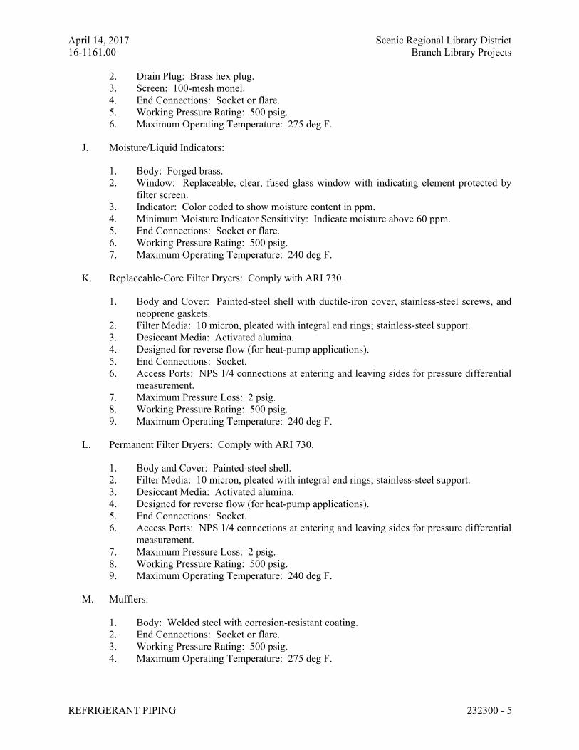
April 14, 2017 Scenic Regional Library District
16-1161.00 Branch Library Projects
REFRIGERANT PIPING 232300 - 5
2. Drain Plug: Brass hex plug.
3. Screen: 100-mesh monel.
4. End Connections: Socket or flare.
5. Working Pressure Rating: 500 psig.
6. Maximum Operating Temperature: 275 deg F.
J. Moisture/Liquid Indicators:
1. Body: Forged brass.
2. Window: Replaceable, clear, fused glass window with indicating element protected by
filter screen.
3. Indicator: Color coded to show moisture content in ppm.
4. Minimum Moisture Indicator Sensitivity: Indicate moisture above 60 ppm.
5. End Connections: Socket or flare.
6. Working Pressure Rating: 500 psig.
7. Maximum Operating Temperature: 240 deg F.
K. Replaceable-Core Filter Dryers: Comply with ARI 730.
1. Body and Cover: Painted-steel shell with ductile-iron cover, stainless-steel screws, and
neoprene gaskets.
2. Filter Media: 10 micron, pleated with integral end rings; stainless-steel support.
3. Desiccant Media: Activated alumina.
4. Designed for reverse flow (for heat-pump applications).
5. End Connections: Socket.
6. Access Ports: NPS 1/4 connections at entering and leaving sides for pressure differential
measurement.
7. Maximum Pressure Loss: 2 psig.
8. Working Pressure Rating: 500 psig.
9. Maximum Operating Temperature: 240 deg F.
L. Permanent Filter Dryers: Comply with ARI 730.
1. Body and Cover: Painted-steel shell.
2. Filter Media: 10 micron, pleated with integral end rings; stainless-steel support.
3. Desiccant Media: Activated alumina.
4. Designed for reverse flow (for heat-pump applications).
5. End Connections: Socket.
6. Access Ports: NPS 1/4 connections at entering and leaving sides for pressure differential
measurement.
7. Maximum Pressure Loss: 2 psig.
8. Working Pressure Rating: 500 psig.
9. Maximum Operating Temperature: 240 deg F.
M. Mufflers:
1. Body: Welded steel with corrosion-resistant coating.
2. End Connections: Socket or flare.
3. Working Pressure Rating: 500 psig.
4. Maximum Operating Temperature: 275 deg F.
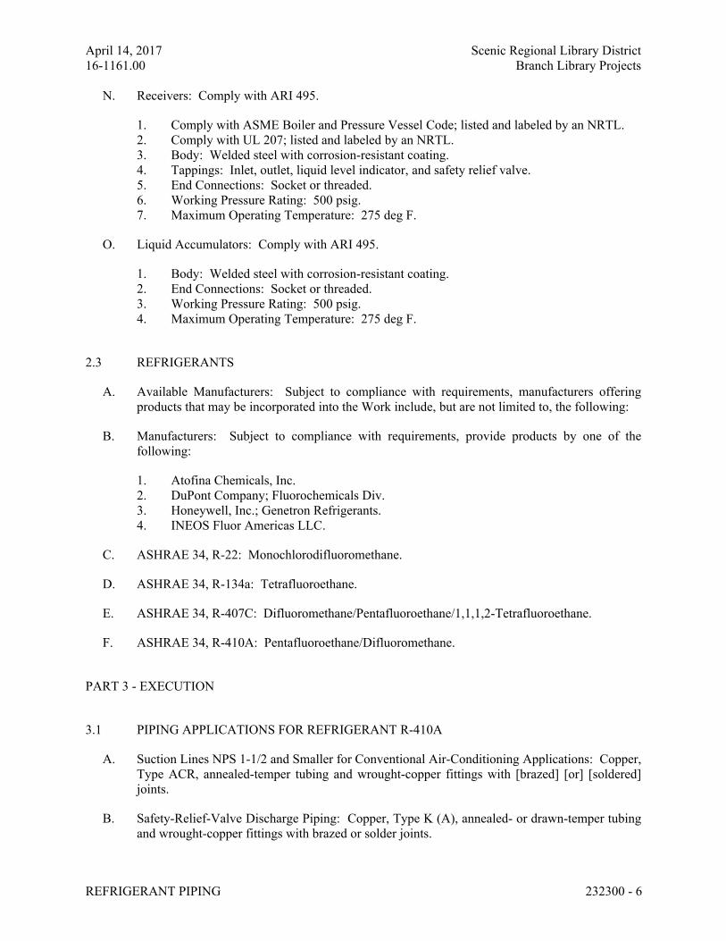
April 14, 2017 Scenic Regional Library District
16-1161.00 Branch Library Projects
REFRIGERANT PIPING 232300 - 6
N. Receivers: Comply with ARI 495.
1. Comply with ASME Boiler and Pressure Vessel Code; listed and labeled by an NRTL.
2. Comply with UL 207; listed and labeled by an NRTL.
3. Body: Welded steel with corrosion-resistant coating.
4. Tappings: Inlet, outlet, liquid level indicator, and safety relief valve.
5. End Connections: Socket or threaded.
6. Working Pressure Rating: 500 psig.
7. Maximum Operating Temperature: 275 deg F.
O. Liquid Accumulators: Comply with ARI 495.
1. Body: Welded steel with corrosion-resistant coating.
2. End Connections: Socket or threaded.
3. Working Pressure Rating: 500 psig.
4. Maximum Operating Temperature: 275 deg F.
2.3 REFRIGERANTS
A. Available Manufacturers: Subject to compliance with requirements, manufacturers offering
products that may be incorporated into the Work include, but are not limited to, the following:
B. Manufacturers: Subject to compliance with requirements, provide products by one of the
following:
1. Atofina Chemicals, Inc.
2. DuPont Company; Fluorochemicals Div.
3. Honeywell, Inc.; Genetron Refrigerants.
4. INEOS Fluor Americas LLC.
C. ASHRAE 34, R-22: Monochlorodifluoromethane.
D. ASHRAE 34, R-134a: Tetrafluoroethane.
E. ASHRAE 34, R-407C: Difluoromethane/Pentafluoroethane/1,1,1,2-Tetrafluoroethane.
F. ASHRAE 34, R-410A: Pentafluoroethane/Difluoromethane.
PART 3 - EXECUTION
3.1 PIPING APPLICATIONS FOR REFRIGERANT R-410A
A. Suction Lines NPS 1-1/2 and Smaller for Conventional Air-Conditioning Applications: Copper,
Type ACR, annealed-temper tubing and wrought-copper fittings with [brazed] [or] [soldered]
joints.
B. Safety-Relief-Valve Discharge Piping: Copper, Type K (A), annealed- or drawn-temper tubing
and wrought-copper fittings with brazed or solder joints.
April 14, 2017 Scenic Regional Library District
16-1161.00 Branch Library Projects
REFRIGERANT PIPING 232300 - 7
C. Safety-Relief-Valve Discharge Piping:
1. NPS 5/8 and Smaller: Copper, Type L, annealed- or drawn-temper tubing and wrought-
copper fittings with braze or soldered joints.
2. NPS 3/4 to NPS 1 and Smaller: Copper, Type K, annealed- or drawn-temper tubing and
wrought-copper fittings with brazed or soldered joints.
3.2 VALVE AND SPECIALTY APPLICATIONS
A. Install diaphragm packless valves in suction and discharge lines of compressor.
B. Install service valves for gage taps at inlet and outlet of hot-gas bypass valves and strainers if
they are not an integral part of valves and strainers.
C. Install a check valve at the compressor discharge and a liquid accumulator at the compressor
suction connection.
D. Except as otherwise indicated, install diaphragm packless valves on inlet and outlet side of filter
dryers.
E. Install a full-sized, three-valve bypass around filter dryers.
F. Install solenoid valves upstream from each expansion valve and hot-gas bypass valve. Install
solenoid valves in horizontal lines with coil at top.
G. Install thermostatic expansion valves as close as possible to distributors on evaporators.
1. Install valve so diaphragm case is warmer than bulb.
2. Secure bulb to clean, straight, horizontal section of suction line using two bulb straps. Do
not mount bulb in a trap or at bottom of the line.
3. If external equalizer lines are required, make connection where it will reflect suction-line
pressure at bulb location.
H. Install safety relief valves where required by ASME Boiler and Pressure Vessel Code. Pipe
safety-relief-valve discharge line to outside according to ASHRAE 15.
I. Install moisture/liquid indicators in liquid line at the inlet of the thermostatic expansion valve or
at the inlet of the evaporator coil capillary tube.
J. Install strainers upstream from and adjacent to the following unless they are furnished as an
integral assembly for device being protected:
1. Solenoid valves.
2. Thermostatic expansion valves.
3. Hot-gas bypass valves.
4. Compressor.
K. Install filter dryers in liquid line between compressor and thermostatic expansion valve, and in
the suction line at the compressor.
April 14, 2017 Scenic Regional Library District
16-1161.00 Branch Library Projects
REFRIGERANT PIPING 232300 - 8
L. Install receivers sized to accommodate pump-down charge.
M. Install flexible connectors at compressors.
3.3 PIPING INSTALLATION
A. Drawing plans, schematics, and diagrams indicate general location and arrangement of piping
systems; indicated locations and arrangements were used to size pipe and calculate friction loss,
expansion, pump sizing, and other design considerations. Install piping as indicated unless
deviations to layout are approved on Shop Drawings.
B. Install refrigerant piping according to ASHRAE 15.
C. Install piping in concealed locations unless otherwise indicated and except in equipment rooms
and service areas.
D. Install piping indicated to be exposed and piping in equipment rooms and service areas at right
angles or parallel to building walls. Diagonal runs are prohibited unless specifically indicated
otherwise.
E. Install piping above accessible ceilings to allow sufficient space for ceiling panel removal.
F. Install piping adjacent to machines to allow service and maintenance.
G. Install piping free of sags and bends.
H. Install fittings for changes in direction and branch connections.
I. Select system components with pressure rating equal to or greater than system operating
pressure.
J. Refer to Section 230900 "Instrumentation and Control for HVAC" and Section 230993
"Sequence of Operations for HVAC Controls" for solenoid valve controllers, control wiring,
and sequence of operation.
K. Install piping as short and direct as possible, with a minimum number of joints, elbows, and
fittings.
L. Arrange piping to allow inspection and service of refrigeration equipment. Install valves and
specialties in accessible locations to allow for service and inspection. Install access doors or
panels as specified in Section 083113 "Access Doors and Frames" if valves or equipment
requiring maintenance is concealed behind finished surfaces.
M. Install refrigerant piping in protective conduit where installed belowground.
N. Install refrigerant piping in rigid or flexible conduit in locations where exposed to mechanical
injury.
O. Slope refrigerant piping as follows:
April 14, 2017 Scenic Regional Library District
16-1161.00 Branch Library Projects
REFRIGERANT PIPING 232300 - 9
1. Install horizontal hot-gas discharge piping with a uniform slope downward away from
compressor.
2. Install horizontal suction lines with a uniform slope downward to compressor.
3. Install traps and double risers to entrain oil in vertical runs.
4. Liquid lines may be installed level.
P. When brazing or soldering, remove solenoid-valve coils and sight glasses; also remove valve
stems, seats, and packing, and accessible internal parts of refrigerant specialties. Do not apply
heat near expansion-valve bulb.
Q. Before installation of steel refrigerant piping, clean pipe and fittings using the following
procedures:
1. Shot blast the interior of piping.
2. Remove coarse particles of dirt and dust by drawing a clean, lintless cloth through tubing
by means of a wire or electrician's tape.
3. Draw a clean, lintless cloth saturated with trichloroethylene through the tube or pipe.
Continue this procedure until cloth is not discolored by dirt.
4. Draw a clean, lintless cloth, saturated with compressor oil, squeezed dry, through the tube
or pipe to remove remaining lint. Inspect tube or pipe visually for remaining dirt and lint.
5. Finally, draw a clean, dry, lintless cloth through the tube or pipe.
6. Safety-relief-valve discharge piping is not required to be cleaned but is required to be
open to allow unrestricted flow.
R. Install piping with adequate clearance between pipe and adjacent walls and hangers or between
pipes for insulation installation.
S. Identify refrigerant piping and valves according to Section 230553 "Identification for HVAC
Piping and Equipment."
T. Install sleeves for piping penetrations of walls, ceilings, and floors. Comply with requirements
for sleeves specified in Section 230517 "Sleeves and Sleeve Seals for HVAC Piping."
U. Install sleeve seals for piping penetrations of concrete walls and slabs. Comply with
requirements for sleeve seals specified in Section 230517 "Sleeves and Sleeve Seals for HVAC
Piping."
V. Install escutcheons for piping penetrations of walls, ceilings, and floors. Comply with
requirements for escutcheons specified in Section 230518 "Escutcheons for HVAC Piping."
3.4 PIPE JOINT CONSTRUCTION
A. Ream ends of pipes and tubes and remove burrs. Bevel plain ends of steel pipe.
B. Remove scale, slag, dirt, and debris from inside and outside of pipe and fittings before
assembly.
C. Fill pipe and fittings with an inert gas (nitrogen or carbon dioxide), during brazing or welding,
to prevent scale formation.
April 14, 2017 Scenic Regional Library District
16-1161.00 Branch Library Projects
REFRIGERANT PIPING 232300 - 10
D. Soldered Joints: Construct joints according to ASTM B 828 or CDA's "Copper Tube
Handbook."
E. Brazed Joints: Construct joints according to AWS's "Brazing Handbook," Chapter "Pipe and
Tube."
1. Use Type BcuP, copper-phosphorus alloy for joining copper socket fittings with copper
pipe.
2. Use Type BAg, cadmium-free silver alloy for joining copper with bronze or steel.
F. Threaded Joints: Thread steel pipe with tapered pipe threads according to ASME B1.20.1. Cut
threads full and clean using sharp dies. Ream threaded pipe ends to remove burrs and restore
full ID. Join pipe fittings and valves as follows:
1. Apply appropriate tape or thread compound to external pipe threads unless dry-seal
threading is specified.
2. Damaged Threads: Do not use pipe or pipe fittings with threads that are corroded or
damaged. Do not use pipe sections that have cracked or open welds.
G. Steel pipe can be threaded, but threaded joints must be seal brazed or seal welded.
H. Welded Joints: Construct joints according to AWS D10.12/D10.12M.
I. Flanged Joints: Select appropriate gasket material, size, type, and thickness for service
application. Install gasket concentrically positioned. Use suitable lubricants on bolt threads.
3.5 HANGERS AND SUPPORTS
A. Hanger, support, and anchor products are specified in Section 230529 "Hangers and Supports
for HVAC Piping and Equipment."
B. Install the following pipe attachments:
1. Adjustable steel clevis hangers for individual horizontal runs less than 20 feet long.
2. Roller hangers and spring hangers for individual horizontal runs 20 feet or longer.
3. Pipe Roller: MSS SP-58, Type 44 for multiple horizontal piping 20 feet or longer,
supported on a trapeze.
4. Spring hangers to support vertical runs.
5. Copper-clad hangers and supports for hangers and supports in direct contact with copper
pipe.
C. Install hangers for copper tubing with the following maximum spacing and minimum rod sizes:
1. NPS 1/2: Maximum span, 60 inches; minimum rod size, 1/4 inch.
2. NPS 5/8: Maximum span, 60 inches; minimum rod size, 1/4 inch.
3. NPS 1: Maximum span, 72 inches; minimum rod size, 1/4 inch.
D. Support multifloor vertical runs at least at each floor.
April 14, 2017 Scenic Regional Library District
16-1161.00 Branch Library Projects
REFRIGERANT PIPING 232300 - 11
3.6 FIELD QUALITY CONTROL
A. Perform tests and inspections and prepare test reports.
B. Tests and Inspections:
1. Comply with ASME B31.5, Chapter VI.
2. Test refrigerant piping, specialties, and receivers. Isolate compressor, condenser,
evaporator, and safety devices from test pressure if they are not rated above the test
pressure.
3. Test high- and low-pressure side piping of each system separately at not less than the
pressures indicated in Part 1 "Performance Requirements" Article.
a. Fill system with nitrogen to the required test pressure.
b. System shall maintain test pressure at the manifold gage throughout duration of
test.
c. Test joints and fittings with electronic leak detector or by brushing a small amount
of soap and glycerin solution over joints.
d. Remake leaking joints using new materials, and retest until satisfactory results are
achieved.
3.7 SYSTEM CHARGING
A. Charge system using the following procedures:
1. Install core in filter dryers after leak test but before evacuation.
2. Evacuate entire refrigerant system with a vacuum pump to 500 micrometers. If vacuum
holds for 12 hours, system is ready for charging.
3. Break vacuum with refrigerant gas, allowing pressure to build up to 2 psig.
4. Charge system with a new filter-dryer core in charging line.
3.8 ADJUSTING
A. Adjust thermostatic expansion valve to obtain proper evaporator superheat.
B. Adjust high- and low-pressure switch settings to avoid short cycling in response to fluctuating
suction pressure.
C. Adjust set-point temperature of air-conditioning or chilled-water controllers to the system
design temperature.
D. Perform the following adjustments before operating the refrigeration system, according to
manufacturer's written instructions:
1. Open shutoff valves in condenser water circuit.
2. Verify that compressor oil level is correct.
3. Open compressor suction and discharge valves.
4. Open refrigerant valves except bypass valves that are used for other purposes.
5. Check open compressor-motor alignment and verify lubrication for motors and bearings.
April 14, 2017 Scenic Regional Library District
16-1161.00 Branch Library Projects
REFRIGERANT PIPING 232300 - 12
E. Replace core of replaceable filter dryer after system has been adjusted and after design flow
rates and pressures are established.
END OF SECTION 232300
April 14, 2017 Scenic Regional Library District
16-1161.00 Branch Library Projects
DUCTWORK 23 31 13 - 1
SECTION 23 31 13– DUCTWORK
ALL LIBRARIES
PART 1 - GENERAL
1.1 RELATED DOCUMENTS
A. Drawings and general provisions of the Contract, including General and Supplementary
Conditions and Division 01 Specification Sections, apply to this Section.
1.2 SUMMARY
A. Section Includes:
1. Single-wall rectangular ducts and fittings.
2. Single-wall round ducts and fittings.
3. Sheet metal materials.
4. Duct liner.
5. Sealants and gaskets.
6. Hangers and supports.
7. Seismic-restraint devices.
B. Related Sections:
1. Section 230593 "Testing, Adjusting, and Balancing for HVAC" for testing, adjusting,
and balancing requirements for metal ducts.
2. Section 233300 "Air Duct Accessories" for dampers, sound-control devices, duct-
mounting access doors and panels, turning vanes, and flexible ducts.
1.3 PERFORMANCE REQUIREMENTS
A. Delegated Duct Design: Duct construction, including sheet metal thicknesses, seam and joint
construction, reinforcements, and hangers and supports, shall comply with SMACNA's "HVAC
Duct Construction Standards - Metal and Flexible" and performance requirements and design
criteria indicated in "Duct Schedule" Article.
B. Structural Performance: Duct hangers and supports and seismic restraints shall withstand the
effects of gravity and seismic loads and stresses within limits and under conditions described in
SMACNA's "HVAC Duct Construction Standards - Metal and Flexible" and ASCE/SEI 7.
1. Seismic Hazard Level A: Seismic force to weight ratio, 0.48.
C. Airstream Surfaces: Surfaces in contact with the airstream shall comply with requirements in
ASHRAE 62.1.
April 14, 2017 Scenic Regional Library District
16-1161.00 Branch Library Projects
DUCTWORK 23 31 13 - 2
1.4 ACTION SUBMITTALS
A. Product Data: For each type of the following products:
1. Liners and adhesives.
2. Sealants and gaskets.
3. Seismic-restraint devices.
B. Delegated-Design Submittal:
1. Sheet metal thicknesses.
2. Joint and seam construction and sealing.
3. Reinforcement details and spacing.
4. Materials, fabrication, assembly, and spacing of hangers and supports.
5. Design Calculations: Calculations, including analysis data signed and sealed by the
qualified professional engineer responsible for their preparation for selecting hangers
and supports and seismic restraints.
1.5 QUALITY ASSURANCE
A. Welding Qualifications: Qualify procedures and personnel according to AWS D1.1/D1.1M,
"Structural Welding Code - Steel," for hangers and supports, AWS D1.2/D1.2M, "Structural
Welding Code - Aluminum," for aluminum supports and AWS D9.1M/D9.1, "Sheet Metal
Welding Code," for duct joint and seam welding.
B. ASHRAE Compliance: Applicable requirements in ASHRAE 62.1, Section 5 - "Systems and
Equipment" and Section 7 - "Construction and System Start-up."
C. ASHRAE/IESNA Compliance: Applicable requirements in ASHRAE/IESNA 90.1,
Section 6.4.4 - "HVAC System Construction and Insulation."
PART 2 - PRODUCTS
2.1 SINGLE-WALL RECTANGULAR DUCTS AND FITTINGS
A. General Fabrication Requirements: Comply with SMACNA's "HVAC Duct Construction
Standards - Metal and Flexible" based on indicated static-pressure class unless otherwise
indicated.
B. Transverse Joints: Select joint types and fabricate according to SMACNA's "HVAC Duct
Construction Standards - Metal and Flexible," Figure 2-1, "Rectangular Duct/Transverse
Joints," for static-pressure class, applicable sealing requirements, materials involved, duct-
support intervals, and other provisions in SMACNA's "HVAC Duct Construction Standards -
Metal and Flexible."
C. Longitudinal Seams: Select seam types and fabricate according to SMACNA's "HVAC Duct
Construction Standards - Metal and Flexible," Figure 2-2, "Rectangular Duct/Longitudinal
Seams," for static-pressure class, applicable sealing requirements, materials involved, duct-
April 14, 2017 Scenic Regional Library District
16-1161.00 Branch Library Projects
DUCTWORK 23 31 13 - 3
support intervals, and other provisions in SMACNA's "HVAC Duct Construction Standards -
Metal and Flexible."
D. Elbows, Transitions, Offsets, Branch Connections, and Other Duct Construction: Select types
and fabricate according to SMACNA's "HVAC Duct Construction Standards - Metal and
Flexible," Chapter 4, "Fittings and Other Construction," for static-pressure class, applicable
sealing requirements, materials involved, duct-support intervals, and other provisions in
SMACNA's "HVAC Duct Construction Standards - Metal and Flexible."
2.2 SINGLE-WALL ROUND DUCTS AND FITTINGS
A. General Fabrication Requirements: Comply with SMACNA's "HVAC Duct Construction
Standards - Metal and Flexible," Chapter 3, "Round, Oval, and Flexible Duct," based on
indicated static-pressure class unless otherwise indicated.
1. Manufacturers: Subject to compliance with requirements, available manufacturers
offering products that may be incorporated into the Work include, but are not limited to,
the following:
a. Lindab Inc.
b. McGill AirFlow LLC.
c. SEMCO Incorporated.
d. Sheet Metal Connectors, Inc.
e. Spiral Manufacturing Co., Inc.
B. Transverse Joints: Select joint types and fabricate according to SMACNA's "HVAC Duct
Construction Standards - Metal and Flexible," Figure 3-1, "Round Duct Transverse Joints," for
static-pressure class, applicable sealing requirements, materials involved, duct-support
intervals, and other provisions in SMACNA's "HVAC Duct Construction Standards - Metal and
Flexible."
C. Longitudinal Seams: Select seam types and fabricate according to SMACNA's "HVAC Duct
Construction Standards - Metal and Flexible," Figure 3-2, "Round Duct Longitudinal Seams,"
for static-pressure class, applicable sealing requirements, materials involved, duct-support
intervals, and other provisions in SMACNA's "HVAC Duct Construction Standards - Metal and
Flexible."
D. Tees and Laterals: Select types and fabricate according to SMACNA's "HVAC Duct
Construction Standards - Metal and Flexible," Figure 3-5, "90 Degree Tees and Laterals," and
Figure 3-6, "Conical Tees," for static-pressure class, applicable sealing requirements, materials
involved, duct-support intervals, and other provisions in SMACNA's "HVAC Duct
Construction Standards - Metal and Flexible."
2.3 SHEET METAL MATERIALS
A. General Material Requirements: Comply with SMACNA's "HVAC Duct Construction
Standards - Metal and Flexible" for acceptable materials, material thicknesses, and duct
construction methods unless otherwise indicated. Sheet metal materials shall be free of pitting,
seam marks, roller marks, stains, discolorations, and other imperfections.
April 14, 2017 Scenic Regional Library District
16-1161.00 Branch Library Projects
DUCTWORK 23 31 13 - 4
B. Galvanized Sheet Steel: Comply with ASTM A 653/A 653M.
1. Galvanized Coating Designation: G60.
2. Finishes for Surfaces Exposed to View: Mill phosphatized.
C. Carbon-Steel Sheets: Comply with ASTM A 1008/A 1008M, with oiled, matte finish for
exposed ducts.
D. Stainless-Steel Sheets: Comply with ASTM A 480/A 480M, Type 304 or 316, as indicated in
the "Duct Schedule" Article; cold rolled, annealed, sheet. Exposed surface finish shall be
No. 2B, No. 2D, No. 3, or No. 4 as indicated in the "Duct Schedule" Article.
E. Aluminum Sheets: Comply with ASTM B 209 (ASTM B 209M) Alloy 3003, H14 temper; with
mill finish for concealed ducts, and standard, one-side bright finish for duct surfaces exposed to
view.
F. Reinforcement Shapes and Plates: ASTM A 36/A 36M, steel plates, shapes, and bars; black
and galvanized.
G. Tie Rods: Galvanized steel, 1/4-inch minimum diameter for lengths 36 inches or less; 3/8-inch
minimum diameter for lengths longer than 36 inches.
2.4 DUCT LINER
A. Fibrous-Glass Duct Liner: Comply with ASTM C 1071, NFPA 90A, or NFPA 90B; and with
NAIMA AH124, "Fibrous Glass Duct Liner Standard."
1. Manufacturers: Subject to compliance with requirements, available manufacturers
offering products that may be incorporated into the Work include, but are not limited to,
the following:
a. CertainTeed Corporation; Insulation Group.
b. Johns Manville.
c. Knauf Insulation.
d. Owens Corning.
2. Maximum Thermal Conductivity:
a. Type II, Rigid: 0.23 Btu x in./h x sq. ft. x deg F at 75 deg F mean temperature.
3. Water-Based Liner Adhesive: Comply with NFPA 90A or NFPA 90B and with
ASTM C 916.
B. Insulation Pins and Washers:
1. Cupped-Head, Capacitor-Discharge-Weld Pins: Copper- or zinc-coated steel pin, fully
annealed for capacitor-discharge welding, 0.106-inch- diameter shank, length to suit
depth of insulation indicated with integral 1-1/2-inch galvanized carbon-steel washer.
April 14, 2017 Scenic Regional Library District
16-1161.00 Branch Library Projects
DUCTWORK 23 31 13 - 5
2. Insulation-Retaining Washers: Self-locking washers formed from 0.016-inch- thick
galvanized steel; with beveled edge sized as required to hold insulation securely in place
but not less than 1-1/2 inches in diameter.
C. Shop Application of Duct Liner: Comply with SMACNA's "HVAC Duct Construction
Standards - Metal and Flexible," Figure 7-11, "Flexible Duct Liner Installation."
1. Adhere a single layer of indicated thickness of duct liner with at least 90 percent
adhesive coverage at liner contact surface area. Attaining indicated thickness with
multiple layers of duct liner is prohibited.
2. Apply adhesive to transverse edges of liner facing upstream that do not receive metal
nosing.
3. Butt transverse joints without gaps, and coat joint with adhesive.
4. Fold and compress liner in corners of rectangular ducts or cut and fit to ensure butted-
edge overlapping.
5. Do not apply liner in rectangular ducts with longitudinal joints, except at corners of
ducts, unless duct size and dimensions of standard liner make longitudinal joints
necessary.
6. Secure liner with mechanical fasteners 4 inches from corners and at intervals not
exceeding 12 inches transversely; at 3 inches from transverse joints and at intervals not
exceeding 18 inches longitudinally.
7. Secure transversely oriented liner edges facing the airstream with metal nosings that
have either channel or "Z" profiles or are integrally formed from duct wall. Fabricate
edge facings at the following locations:
a. Fan discharges.
b. Intervals of lined duct preceding unlined duct.
c. Upstream edges of transverse joints in ducts where air velocities are higher than
2500 fpm or where indicated.
8. Terminate inner ducts with buildouts attached to fire-damper sleeves, dampers, turning
vane assemblies, or other devices. Fabricated buildouts (metal hat sections) or other
buildout means are optional; when used, secure buildouts to duct walls with bolts,
screws, rivets, or welds.
2.5 SEALANT AND GASKETS
A. General Sealant and Gasket Requirements: Surface-burning characteristics for sealants and
gaskets shall be a maximum flame-spread index of 25 and a maximum smoke-developed index
of 50 when tested according to UL 723; certified by an NRTL.
B. Two-Part Tape Sealing System:
1. Tape: Woven cotton fiber impregnated with mineral gypsum and modified
acrylic/silicone activator to react exothermically with tape to form hard, durable, airtight
seal.
2. Tape Width: 4 inches.
3. Sealant: Modified styrene acrylic.
4. Water resistant.
April 14, 2017 Scenic Regional Library District
16-1161.00 Branch Library Projects
DUCTWORK 23 31 13 - 6
5. Mold and mildew resistant.
6. Maximum Static-Pressure Class: 10-inch wg (2500 Pa), positive and negative.
7. Service: Indoor and outdoor.
8. Service Temperature: Minus 40 to plus 200 deg F (Minus 40 to plus 93 deg C).
9. Substrate: Compatible with galvanized sheet steel (both PVC coated and bare), stainless
steel, or aluminum.
C. Water-Based Joint and Seam Sealant:
1. Application Method: Brush on.
2. Solids Content: Minimum 65 percent.
3. Shore A Hardness: Minimum 20.
4. Water resistant.
5. Mold and mildew resistant.
6. VOC: Maximum 75 g/L (less water).
7. Maximum Static-Pressure Class: 10-inch wg, positive and negative.
8. Service: Indoor or outdoor.
9. Substrate: Compatible with galvanized sheet steel (both PVC coated and bare), stainless
steel, or aluminum sheets.
D. Flanged Joint Sealant: Comply with ASTM C 920.
1. General: Single-component, acid-curing, silicone, elastomeric.
2. Type: S.
3. Grade: NS.
4. Class: 25.
5. Use: O.
E. Flange Gaskets: Butyl rubber, neoprene, or EPDM polymer with polyisobutylene plasticizer.
F. Round Duct Joint O-Ring Seals:
1. Seal shall provide maximum leakage class of 3 cfm/100 sq. ft. at 1-inch wg and shall be
rated for 10-inch wg static-pressure class, positive or negative.
2. EPDM O-ring to seal in concave bead in coupling or fitting spigot.
3. Double-lipped, EPDM O-ring seal, mechanically fastened to factory-fabricated couplings
and fitting spigots.
2.6 HANGERS AND SUPPORTS
A. Hanger Rods for Noncorrosive Environments: Cadmium-plated steel rods and nuts.
B. Hanger Rods for Corrosive Environments (Apparatus Bay): Electrogalvanized, all-thread rods
or galvanized rods with threads painted with zinc-chromate primer after installation.
C. Strap and Rod Sizes: Comply with SMACNA's "HVAC Duct Construction Standards - Metal
and Flexible," Table 5-1, "Rectangular Duct Hangers Minimum Size," and Table 5-2,
"Minimum Hanger Sizes for Round Duct."
D. Steel Cables for Galvanized-Steel Ducts: Galvanized steel complying with ASTM A 603.
April 14, 2017 Scenic Regional Library District
16-1161.00 Branch Library Projects
DUCTWORK 23 31 13 - 7
E. Steel Cables for Stainless-Steel Ducts: Stainless steel complying with ASTM A 492.
F. Steel Cable End Connections: Cadmium-plated steel assemblies with brackets, swivel, and
bolts designed for duct hanger service; with an automatic-locking and clamping device.
G. Duct Attachments: Sheet metal screws, blind rivets, or self-tapping metal screws; compatible
with duct materials.
H. Trapeze and Riser Supports:
1. Supports for Galvanized-Steel Ducts: Galvanized-steel shapes and plates.
2. Supports for Stainless-Steel Ducts: Stainless-steel shapes and plates.
3. Supports for Aluminum Ducts: Aluminum or galvanized steel coated with zinc
chromate.
2.7 SEISMIC-RESTRAINT DEVICES
A. Manufacturers: Subject to compliance with requirements, available manufacturers offering
products that may be incorporated into the Work include, but are not limited to, the following:
1. Cooper B-Line, Inc.; a division of Cooper Industries.
2. Ductmate Industries, Inc.
3. Hilti Corp.
4. Kinetics Noise Control.
5. Loos & Co.; Cableware Division.
6. Mason Industries.
7. TOLCO; a brand of NIBCO INC.
8. Unistrut Corporation; Tyco International, Ltd.
B. General Requirements for Restraint Components: Rated strengths, features, and applications
shall be as defined in reports by an agency acceptable to authorities having jurisdiction.
1. Structural Safety Factor: Allowable strength in tension, shear, and pullout force of
components shall be at least four times the maximum seismic forces to which they will
be subjected.
C. Channel Support System: Shop- or field-fabricated support assembly made of slotted steel
channels rated in tension, compression, and torsion forces and with accessories for attachment
to braced component at one end and to building structure at the other end. Include matching
components and corrosion-resistant coating.
D. Restraint Cables: ASTM A 603, galvanized-steel cables with end connections made of
cadmium-plated steel assemblies with brackets, swivel, and bolts designed for restraining cable
service; and with an automatic-locking and clamping device or double-cable clips.
E. Hanger Rod Stiffener: Reinforcing steel angle clamped to hanger rod.
F. Mechanical Anchor Bolts: Drilled-in and stud-wedge or female-wedge type. Select anchor
bolts with strength required for anchor and as tested according to ASTM E 488.
April 14, 2017 Scenic Regional Library District
16-1161.00 Branch Library Projects
DUCTWORK 23 31 13 - 8
PART 3 - EXECUTION
3.1 DUCT INSTALLATION
A. Drawing plans, schematics, and diagrams indicate general location and arrangement of duct
system. Indicated duct locations, configurations, and arrangements were used to size ducts and
calculate friction loss for air-handling equipment sizing and for other design considerations.
Install duct systems as indicated unless deviations to layout are approved on Shop Drawings
and Coordination Drawings.
B. Install ducts according to SMACNA's "HVAC Duct Construction Standards - Metal and
Flexible" unless otherwise indicated.
C. Install ducts with fewest possible joints.
D. Install factory- or shop-fabricated fittings for changes in direction, size, and shape and for
branch connections.
E. Unless otherwise indicated, install ducts vertically and horizontally, and parallel and
perpendicular to building lines.
F. Install ducts close to walls, overhead construction, columns, and other structural and permanent
enclosure elements of building.
G. Install ducts with a clearance of 1 inch, plus allowance for insulation thickness.
H. Route ducts to avoid passing through transformer vaults and electrical equipment rooms and
enclosures.
I. Where ducts pass through non-fire-rated interior partitions and exterior walls and are exposed
to view, cover the opening between the partition and duct or duct insulation with sheet metal
flanges of same metal thickness as the duct. Overlap openings on four sides by at least 1-1/2
inches.
J. Where ducts pass through fire-rated interior partitions and exterior walls, install fire dampers.
Comply with requirements in Section 233300 "Air Duct Accessories" for fire and smoke
dampers.
K. Protect duct interiors from moisture, construction debris and dust, and other foreign
materials. Comply with SMACNA's "IAQ Guidelines for Occupied Buildings Under
Construction," Appendix G, "Duct Cleanliness for New Construction Guidelines."
3.2 INSTALLATION OF EXPOSED DUCTWORK
A. Protect ducts exposed in finished spaces from being dented, scratched, or damaged.
B. Trim duct sealants flush with metal. Create a smooth and uniform exposed bead. Do not use
two-part tape sealing system.
April 14, 2017 Scenic Regional Library District
16-1161.00 Branch Library Projects
DUCTWORK 23 31 13 - 9
C. Grind welds to provide smooth surface free of burrs, sharp edges, and weld splatter. When
welding stainless steel with a No. 3 or 4 finish, grind the welds flush, polish the exposed welds,
and treat the welds to remove discoloration caused by welding.
D. Maintain consistency, symmetry, and uniformity in the arrangement and fabrication of fittings,
hangers and supports, duct accessories, and air outlets.
E. Repair or replace damaged sections and finished work that does not comply with these
requirements.
3.3 ADDITIONAL INSTALLATION REQUIREMENTS FOR COMMERCIAL KITCHEN
HOOD EXHAUST DUCT
A. Install commercial kitchen hood exhaust ducts without dips and traps that may hold grease, and
sloped a minimum of 2 percent to drain grease back to the hood.
B. Install fire-rated access panel assemblies at each change in direction and at maximum intervals
of 12 feet in horizontal ducts, and at every floor for vertical ducts, or as indicated on Drawings.
Locate access panel on top or sides of duct a minimum of 1-1/2 inches (38 mm) from bottom of
duct.
C. Do not penetrate fire-rated assemblies except as allowed by applicable building codes and
authorities having jurisdiction.
3.4 DUCT SEALING
A. Seal ducts for duct static-pressure, seal classes, and leakage classes specified in "Duct
Schedule" Article according to SMACNA's "HVAC Duct Construction Standards - Metal and
Flexible."
B. Seal ducts to the following seal classes according to SMACNA's "HVAC Duct Construction
Standards - Metal and Flexible":
1. Comply with SMACNA's "HVAC Duct Construction Standards - Metal and Flexible."
2. Outdoor, Supply-Air Ducts: Seal Class A.
3. Outdoor, Exhaust Ducts: Seal Class C.
4. Outdoor, Return-Air Ducts: Seal Class C.
5. Unconditioned Space, Supply-Air Ducts in Pressure Classes 2-Inch wg (500 Pa) and
Lower: Seal Class B.
6. Unconditioned Space, Supply-Air Ducts in Pressure Classes Higher Than 2-Inch wg (500
Pa): Seal Class A.
7. Unconditioned Space, Exhaust Ducts: Seal Class C.
8. Unconditioned Space, Return-Air Ducts: Seal Class B.
9. Conditioned Space, Supply-Air Ducts in Pressure Classes 2-Inch wg (500 Pa) and
Lower: Seal Class C.
10. Conditioned Space, Supply-Air Ducts in Pressure Classes Higher Than 2-Inch wg (500
Pa): Seal Class B.
11. Conditioned Space, Exhaust Ducts: Seal Class B.
April 14, 2017 Scenic Regional Library District
16-1161.00 Branch Library Projects
DUCTWORK 23 31 13 - 10
12. Conditioned Space, Return-Air Ducts: Seal Class C.
3.5 HANGER AND SUPPORT INSTALLATION
A. Comply with SMACNA's "HVAC Duct Construction Standards - Metal and Flexible,"
Chapter 5, "Hangers and Supports."
B. Building Attachments: Concrete inserts, powder-actuated fasteners, or structural-steel fasteners
appropriate for construction materials to which hangers are being attached.
1. Where practical, install concrete inserts before placing concrete.
2. Install powder-actuated concrete fasteners after concrete is placed and completely cured.
3. Use powder-actuated concrete fasteners for standard-weight aggregate concretes or for
slabs more than 4 inches thick.
4. Do not use powder-actuated concrete fasteners for lightweight-aggregate concretes or for
slabs less than 4 inches thick.
5. Do not use powder-actuated concrete fasteners for seismic restraints.
C. Hanger Spacing: Comply with SMACNA's "HVAC Duct Construction Standards - Metal and
Flexible," Table 5-1, "Rectangular Duct Hangers Minimum Size," and Table 5-2, "Minimum
Hanger Sizes for Round Duct," for maximum hanger spacing; install hangers and supports
within 24 inches of each elbow and within 48 inches of each branch intersection.
D. Hangers Exposed to View: Threaded rod and angle or channel supports.
E. Support vertical ducts with steel angles or channel secured to the sides of the duct with welds,
bolts, sheet metal screws, or blind rivets; support at each floor and at a maximum intervals of
16 feet.
F. Install upper attachments to structures. Select and size upper attachments with pull-out,
tension, and shear capacities appropriate for supported loads and building materials where
used.
3.6 SEISMIC-RESTRAINT-DEVICE INSTALLATION
A. Install ducts with hangers and braces designed to support the duct and to restrain against
seismic forces required by applicable building codes. Comply with ASCE/SEI 7.
1. Space lateral supports a maximum of 40 feet o.c., and longitudinal supports a maximum
of 80 feet o.c.
2. Brace a change of direction longer than 12 feet.
B. Select seismic-restraint devices with capacities adequate to carry present and future static and
seismic loads.
C. Install cables so they do not bend across edges of adjacent equipment or building structure.
D. Install cable restraints on ducts that are suspended with vibration isolators.
E. Install seismic-restraint devices using methods approved by an agency acceptable to authorities
having jurisdiction.
April 14, 2017 Scenic Regional Library District
16-1161.00 Branch Library Projects
DUCTWORK 23 31 13 - 11
F. Attachment to Structure: If specific attachment is not indicated, anchor bracing and restraints
to structure, to flanges of beams, to upper truss chords of bar joists, or to concrete members.
G. Drilling for and Setting Anchors:
1. Identify position of reinforcing steel and other embedded items prior to drilling holes for
anchors. Do not damage existing reinforcement or embedded items during drilling.
Notify the Architect if reinforcing steel or other embedded items are encountered during
drilling. Locate and avoid prestressed tendons, electrical and telecommunications
conduit, and gas lines.
2. Do not drill holes in concrete or masonry until concrete, mortar, or grout has achieved
full design strength.
3. Wedge Anchors: Protect threads from damage during anchor installation. Heavy-duty
sleeve anchors shall be installed with sleeve fully engaged in the structural element to
which anchor is to be fastened.
4. Set anchors to manufacturer's recommended torque, using a torque wrench.
5. Install zinc-coated steel anchors for interior applications and stainless-steel anchors for
applications exposed to weather.
3.7 CONNECTIONS
A. Make connections to equipment with flexible connectors complying with Section 233300 "Air
Duct Accessories."
B. Comply with SMACNA's "HVAC Duct Construction Standards - Metal and Flexible" for
branch, outlet and inlet, and terminal unit connections.
3.8 PAINTING
A. Paint interior of metal ducts that are visible through registers and grilles and that do not have
duct liner. Apply one coat of flat, black, latex paint over a compatible galvanized-steel primer.
Paint materials and application requirements are specified in Section 099113 "Exterior
Painting" and Section 099123 "Interior Painting."
3.9 START UP
A. Air Balance: Comply with requirements in Section 230593 "Testing, Adjusting, and Balancing
for HVAC."
3.10 DUCT SCHEDULE
A. Fabricate ducts with galvanized sheet steel except as otherwise indicated and as follows:
1. Exhaust ducts serving shower rooms from air device to main: Aluminum.
2. Concealed ducts serving type 1 exhaust hoods: Carbon Steel
3. Exposed ducts serving type 1 exhaust hoods: Stainless Steel
April 14, 2017 Scenic Regional Library District
16-1161.00 Branch Library Projects
DUCTWORK 23 31 13 - 12
B. Supply Ducts:
1. Ducts Connected to Fan Coil Units, Furnaces, Heat Pumps, and Terminal Units:
a. Pressure Class: Positive 2-inch wg.
b. Minimum SMACNA Seal Class: C.
c. SMACNA Leakage Class for Rectangular: 24.
d. SMACNA Leakage Class for Round and Flat Oval: 12.
2. Ducts Connected to Equipment Not Listed Above:
a. Pressure Class: Positive 3-inch wg.
b. Minimum SMACNA Seal Class: B.
c. SMACNA Leakage Class for Rectangular: 12.
d. SMACNA Leakage Class for Round and Flat Oval: 6.
C. Return Ducts:
1. Ducts Connected to Fan Coil Units, Furnaces, Heat Pumps, and Terminal Units:
a. Pressure Class: Positive or negative 1-inch wg.
b. Minimum SMACNA Seal Class: C.
c. SMACNA Leakage Class for Rectangular: 24.
d. SMACNA Leakage Class for Round and Flat Oval: 12.
2. Ducts Connected to Air-Handling Units:
a. Pressure Class: Positive or negative 2-inch wg.
b. Minimum SMACNA Seal Class: B.
c. SMACNA Leakage Class for Rectangular: 12.
d. SMACNA Leakage Class for Round and Flat Oval: 6.
3. Ducts Connected to Equipment Not Listed Above:
a. Pressure Class: Positive or negative 2-inch wg.
b. Minimum SMACNA Seal Class: B.
c. SMACNA Leakage Class for Rectangular: 6.
d. SMACNA Leakage Class for Round and Flat Oval: 6.
D. Exhaust Ducts:
1. Ducts Connected to Fans Exhausting (ASHRAE 62.1, Class 1 and 2) Air:
a. Pressure Class: Negative 2-inch wg.
b. Minimum SMACNA Seal Class: C if negative pressure, and A if positive
pressure.
c. SMACNA Leakage Class for Rectangular: 24.
d. SMACNA Leakage Class for Round and Flat Oval: 12.
2. Ducts Connected to Air-Handling Units:
April 14, 2017 Scenic Regional Library District
16-1161.00 Branch Library Projects
DUCTWORK 23 31 13 - 13
a. Pressure Class: Positive or negative 3-inch wg.
b. Minimum SMACNA Seal Class: B if negative pressure, and A if positive
pressure.
c. SMACNA Leakage Class for Rectangular: 12.
d. SMACNA Leakage Class for Round and Flat Oval: 6.
3. Ducts Connected to Commercial Kitchen Hoods: Comply with NFPA 96.
a. Exposed to View: Type 304, stainless-steel sheet, No. 4 finish.
b. Concealed: Carbon-steel sheet.
c. Welded seams and joints.
d. Pressure Class: Positive or negative 2-inch wg.
e. Minimum SMACNA Seal Class: Welded seams, joints, and penetrations.
f. SMACNA Leakage Class: 3.
4. Ducts Connected to Equipment Not Listed Above:
a. Pressure Class: Positive or negative 2-inch wg.
b. Minimum SMACNA Seal Class: B if negative pressure, and A if positive
pressure.
c. SMACNA Leakage Class for Rectangular: 12.
d. SMACNA Leakage Class for Round and Flat Oval: 6.
E. Outdoor-Air (Not Filtered, Heated, or Cooled) Ducts:
1. Ducts Connected to Fan Coil Units, Furnaces, Heat Pumps, and Terminal Units:
a. Pressure Class: Positive or negative 2-inch wg.
b. Minimum SMACNA Seal Class: B.
c. SMACNA Leakage Class for Rectangular: 12.
d. SMACNA Leakage Class for Round and Flat Oval: 6.
2. Ducts Connected to Air-Handling Units:
a. Pressure Class: Positive or negative 2-inch wg.
b. Minimum SMACNA Seal Class: B.
c. SMACNA Leakage Class for Rectangular: 12.
d. SMACNA Leakage Class for Round and Flat Oval: 6.
3. Ducts Connected to Equipment Not Listed Above:
a. Pressure Class: Positive or negative 2-inch wg.
b. Minimum SMACNA Seal Class: B.
c. SMACNA Leakage Class for Rectangular: 12.
d. SMACNA Leakage Class for Round and Flat Oval: 6.
F. Intermediate Reinforcement:
1. Galvanized-Steel Ducts: Galvanized steel or carbon steel coated with zinc-chromate
primer.
April 14, 2017 Scenic Regional Library District
16-1161.00 Branch Library Projects
DUCTWORK 23 31 13 - 14
G. Liner:
1. Rectangular Supply Air Ducts: Fibrous glass, Type I, 1 inch thick.
2. Rectangular Return Air Ducts: Fibrous glass, Type I, 1 inch thick.
H. Elbow Configuration:
1. Rectangular Duct: Comply with SMACNA's "HVAC Duct Construction Standards -
Metal and Flexible," Figure 4-2, "Rectangular Elbows."
a. Velocity 1000 fpm or Lower:
1) Radius Type RE 1 with minimum 0.5 radius-to-diameter ratio.
2) Mitered Type RE 4 without vanes.
b. Velocity 1000 to 1500 fpm :
1) Radius Type RE 1 with minimum 1.0 radius-to-diameter ratio.
2) Radius Type RE 3 with minimum 0.5 radius-to-diameter ratio and two
vanes.
3) Mitered Type RE 2 with vanes complying with SMACNA's "HVAC Duct
Construction Standards - Metal and Flexible," Figure 4-3, "Vanes and Vane
Runners," and Figure 4-4, "Vane Support in Elbows."
c. Velocity 1500 fpm or Higher:
1) Radius Type RE 1 with minimum 1.5 radius-to-diameter ratio.
2) Radius Type RE 3 with minimum 1.0 radius-to-diameter ratio and two
vanes.
3) Mitered Type RE 2 with vanes complying with SMACNA's "HVAC Duct
Construction Standards - Metal and Flexible," Figure 4-3, "Vanes and Vane
Runners," and Figure 4-4, "Vane Support in Elbows."
2. Rectangular Duct: Comply with SMACNA's "HVAC Duct Construction Standards -
Metal and Flexible," Figure 4-2, "Rectangular Elbows."
a. Radius Type RE 1 with minimum 1.5 radius-to-diameter ratio.
b. Radius Type RE 3 with minimum 1.0 radius-to-diameter ratio and two vanes.
c. Mitered Type RE 2 with vanes complying with SMACNA's "HVAC Duct
Construction Standards - Metal and Flexible," Figure 4-3, "Vanes and Vane
Runners," and Figure 4-4, "Vane Support in Elbows."
3. Round Duct: Comply with SMACNA's "HVAC Duct Construction Standards - Metal
and Flexible," Figure 3-4, "Round Duct Elbows."
a. Minimum Radius-to-Diameter Ratio and Elbow Segments: Comply with
SMACNA's "HVAC Duct Construction Standards - Metal and Flexible," Table 3-
1, "Mitered Elbows." Elbows with less than 90-degree change of direction have
proportionately fewer segments.
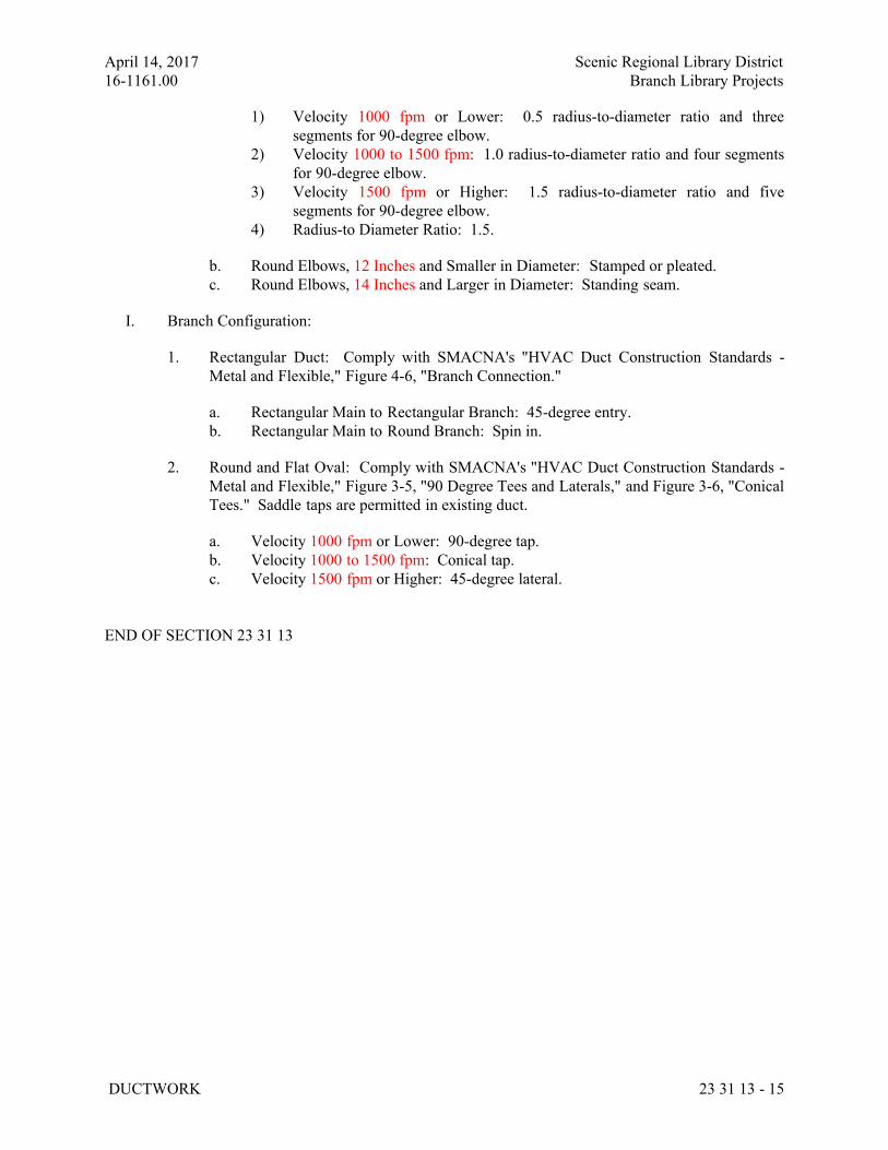
April 14, 2017 Scenic Regional Library District
16-1161.00 Branch Library Projects
DUCTWORK 23 31 13 - 15
1) Velocity 1000 fpm or Lower: 0.5 radius-to-diameter ratio and three
segments for 90-degree elbow.
2) Velocity 1000 to 1500 fpm: 1.0 radius-to-diameter ratio and four segments
for 90-degree elbow.
3) Velocity 1500 fpm or Higher: 1.5 radius-to-diameter ratio and five
segments for 90-degree elbow.
4) Radius-to Diameter Ratio: 1.5.
b. Round Elbows, 12 Inches and Smaller in Diameter: Stamped or pleated.
c. Round Elbows, 14 Inches and Larger in Diameter: Standing seam.
I. Branch Configuration:
1. Rectangular Duct: Comply with SMACNA's "HVAC Duct Construction Standards -
Metal and Flexible," Figure 4-6, "Branch Connection."
a. Rectangular Main to Rectangular Branch: 45-degree entry.
b. Rectangular Main to Round Branch: Spin in.
2. Round and Flat Oval: Comply with SMACNA's "HVAC Duct Construction Standards -
Metal and Flexible," Figure 3-5, "90 Degree Tees and Laterals," and Figure 3-6, "Conical
Tees." Saddle taps are permitted in existing duct.
a. Velocity 1000 fpm or Lower: 90-degree tap.
b. Velocity 1000 to 1500 fpm: Conical tap.
c. Velocity 1500 fpm or Higher: 45-degree lateral.
END OF SECTION 23 31 13
April 14, 2017 Scenic Regional Library District
16-1161.00 Branch Library Projects
METAL DUCTS 233113 - 1
SECTION 233113 - METAL DUCTS
ALL LIBRARIES
PART 1 - GENERAL
1.1 RELATED DOCUMENTS
A. Drawings and general provisions of the Contract, including General and Supplementary
Conditions and Division 01 Specification Sections, apply to this Section.
1.2 SUMMARY
A. Section Includes:
1. Single-wall rectangular ducts and fittings.
2. Double-wall rectangular ducts and fittings.
3. Single-wall round ducts and fittings.
4. Double-wall round ducts and fittings.
5. Sheet metal materials.
6. Duct liner.
7. Sealants and gaskets.
8. Hangers and supports.
9. Seismic-restraint devices.
B. Related Sections:
1. Section 230593 "Testing, Adjusting, and Balancing for HVAC" for testing, adjusting, and
balancing requirements for metal ducts.
2. Section 233116 "Nonmetal Ducts" for fibrous-glass ducts, thermoset fiber-reinforced
plastic ducts, thermoplastic ducts, PVC ducts, and concrete ducts.
3. Section 233119 "HVAC Casings" for factory- and field-fabricated casings for mechanical
equipment.
4. Section 233300 "Air Duct Accessories" for dampers, sound-control devices, duct-
mounting access doors and panels, turning vanes, and flexible ducts.
1.3 PERFORMANCE REQUIREMENTS
A. Delegated Duct Design: Duct construction, including sheet metal thicknesses, seam and joint
construction, reinforcements, and hangers and supports, shall comply with SMACNA's "HVAC
Duct Construction Standards - Metal and Flexible" and performance requirements and design
criteria indicated in "Duct Schedule" Article. Minimum sheet metal thickness shall be 24 gage.
B. Structural Performance: Duct hangers and supports and seismic restraints shall withstand the
effects of gravity[ and seismic] loads and stresses within limits and under conditions described
April 14, 2017 Scenic Regional Library District
16-1161.00 Branch Library Projects
METAL DUCTS 233113 - 2
in SMACNA's "HVAC Duct Construction Standards - Metal and Flexible" and SMACNA's
"Seismic Restraint Manual: Guidelines for Mechanical Systems."
1. Seismic Hazard Level A: Seismic force to weight ratio, 0.48.
2. Seismic Hazard Level B: Seismic force to weight ratio, 0.30.
3. Seismic Hazard Level C: Seismic force to weight ratio, 0.15.
C. Airstream Surfaces: Surfaces in contact with the airstream shall comply with requirements in
ASHRAE 62.1.
1.4 ACTION SUBMITTALS
A. Product Data: For each type of the following products:
1. Liners and adhesives.
2. Sealants and gaskets.
3. Seismic-restraint devices.
B. Shop Drawings:
1. Fabrication, assembly, and installation, including plans, elevations, sections, components,
and attachments to other work.
2. Factory- and shop-fabricated ducts and fittings.
3. Duct layout indicating sizes, configuration, liner material, and static-pressure classes.
4. Elevation of top of ducts.
5. Dimensions of main duct runs from building grid lines.
6. Fittings.
7. Reinforcement and spacing.
8. Seam and joint construction.
9. Penetrations through fire-rated and other partitions.
10. Equipment installation based on equipment being used on Project.
11. Locations for duct accessories, including dampers, turning vanes, and access doors and
panels.
12. Hangers and supports, including methods for duct and building attachment, seismic
restraints, and vibration isolation.
C. Delegated-Design Submittal:
1. Sheet metal thicknesses, except that all sheet metal shall be at least 24 gage.
2. Joint and seam construction and sealing.
3. Reinforcement details and spacing.
4. Materials, fabrication, assembly, and spacing of hangers and supports.
5. Design Calculations: Calculations, including analysis data signed and sealed by the
qualified professional engineer responsible for their preparation for selecting hangers and
supports and seismic restraints.
April 14, 2017 Scenic Regional Library District
16-1161.00 Branch Library Projects
METAL DUCTS 233113 - 3
1.5 INFORMATIONAL SUBMITTALS
A. Coordination Drawings: Plans, drawn to scale, on which the following items are shown and
coordinated with each other, using input from installers of the items involved:
1. Duct installation in congested spaces, indicating coordination with general construction,
building components, and other building services. Indicate proposed changes to duct
layout.
2. Suspended ceiling components.
3. Structural members to which duct will be attached.
4. Size and location of initial access modules for acoustical tile.
5. Penetrations of smoke barriers and fire-rated construction.
6. Items penetrating finished ceiling including the following:
a. Lighting fixtures.
b. Air outlets and inlets.
c. Speakers.
d. Sprinklers.
e. Access panels.
f. Perimeter moldings.
B. Welding certificates.
C. Field quality-control reports.
1.6 QUALITY ASSURANCE
A. Welding Qualifications: Qualify procedures and personnel according to AWS D1.1/D1.1M,
"Structural Welding Code - Steel," for hangers and supports.
B. Welding Qualifications: Qualify procedures and personnel according to the following:
1. AWS D1.1/D1.1M, "Structural Welding Code - Steel," for hangers and supports.
2. AWS D1.2/D1.2M, "Structural Welding Code - Aluminum," for aluminum supports.
3. AWS D9.1M/D9.1, "Sheet Metal Welding Code," for duct joint and seam welding.
C. ASHRAE Compliance: Applicable requirements in ASHRAE 62.1, Section 5 - "Systems and
Equipment" and Section 7 - "Construction and System Start-up."
D. ASHRAE/IESNA Compliance: Applicable requirements in ASHRAE/IESNA 90.1,
Section 6.4.4 - "HVAC System Construction and Insulation."
April 14, 2017 Scenic Regional Library District
16-1161.00 Branch Library Projects
METAL DUCTS 233113 - 4
PART 2 - PRODUCTS
2.1 SINGLE-WALL RECTANGULAR DUCTS AND FITTINGS
A. General Fabrication Requirements: Comply with SMACNA's "HVAC Duct Construction
Standards - Metal and Flexible" based on indicated static-pressure class unless otherwise
indicated.
B. Transverse Joints: Select joint types and fabricate according to SMACNA's "HVAC Duct
Construction Standards - Metal and Flexible," Figure 2-1, "Rectangular Duct/Transverse
Joints," for static-pressure class, applicable sealing requirements, materials involved, duct-
support intervals, and other provisions in SMACNA's "HVAC Duct Construction Standards -
Metal and Flexible."
C. Longitudinal Seams: Select seam types and fabricate according to SMACNA's "HVAC Duct
Construction Standards - Metal and Flexible," Figure 2-2, "Rectangular Duct/Longitudinal
Seams," for static-pressure class, applicable sealing requirements, materials involved, duct-
support intervals, and other provisions in SMACNA's "HVAC Duct Construction Standards -
Metal and Flexible."
D. Elbows, Transitions, Offsets, Branch Connections, and Other Duct Construction: Select types
and fabricate according to SMACNA's "HVAC Duct Construction Standards - Metal and
Flexible," Chapter 4, "Fittings and Other Construction," for static-pressure class, applicable
sealing requirements, materials involved, duct-support intervals, and other provisions in
SMACNA's "HVAC Duct Construction Standards - Metal and Flexible."
2.2 DOUBLE-WALL RECTANGULAR DUCTS AND FITTINGS
A. Manufacturers: Subject to compliance with requirements, provide products by one of the
following:
1. McGill AirFlow LLC.
2. Sheet Metal Connectors, Inc.
B. Rectangular Ducts: Fabricate ducts with indicated dimensions for the inner duct.
C. Outer Duct: Comply with SMACNA's "HVAC Duct Construction Standards - Metal and
Flexible" based on indicated static-pressure class unless otherwise indicated.
D. Transverse Joints: Select joint types and fabricate according to SMACNA's "HVAC Duct
Construction Standards - Metal and Flexible," Figure 2-1, "Rectangular Duct/Transverse
Joints," for static-pressure class, applicable sealing requirements, materials involved, duct-
support intervals, and other provisions in SMACNA's "HVAC Duct Construction Standards -
Metal and Flexible."
E. Longitudinal Seams: Select seam types and fabricate according to SMACNA's "HVAC Duct
Construction Standards - Metal and Flexible," Figure 2-2, "Rectangular Duct/Longitudinal
Seams," for static-pressure class, applicable sealing requirements, materials involved, duct-
April 14, 2017 Scenic Regional Library District
16-1161.00 Branch Library Projects
METAL DUCTS 233113 - 5
support intervals, and other provisions in SMACNA's "HVAC Duct Construction Standards -
Metal and Flexible."
F. Interstitial Insulation: Fibrous-glass liner complying with ASTM C 1071, NFPA 90A, or
NFPA 90B; and with NAIMA AH124, "Fibrous Glass Duct Liner Standard."
1. Maximum Thermal Conductivity: 0.27 Btu x in./h x sq. ft. x deg F at 75 deg F mean
temperature.
2. Install spacers that position the inner duct at uniform distance from outer duct without
compressing insulation.
3. Coat insulation with antimicrobial coating.
4. Cover insulation with polyester film complying with UL 181, Class 1.
G. Interstitial Insulation: Flexible elastomeric duct liner complying with ASTM C 534, Type II for
sheet materials, and with NFPA 90A or NFPA 90B.
1. Maximum Thermal Conductivity: [0.25 Btu x in./h x sq. ft. x deg F (0.034 W/m x K)]
<Insert conductivity> at 75 deg F (24 deg C) mean temperature.
H. Inner Duct: Minimum 0.028-inch (0.7-mm) [perforated galvanized sheet steel having 3/32-
inch- (2.4-mm-) diameter perforations, with overall open area of 23 percent] [solid sheet
steel].
I. Formed-on Transverse Joints (Flanges): Select joint types and fabricate according to
SMACNA's "HVAC Duct Construction Standards - Metal and Flexible," Figure 2-1,
"Rectangular Duct/Traverse Joints," for static-pressure class, applicable sealing requirements,
materials involved, duct-support intervals, and other provisions in SMACNA's "HVAC Duct
Construction Standards - Metal and Flexible."
J. Longitudinal Seams: Select seam types and fabricate according to SMACNA's "HVAC Duct
Construction Standards - Metal and Flexible," Figure 2-2, "Rectangular Duct/Longitudinal
Seams," for static-pressure class, applicable sealing requirements, materials involved, duct-
support intervals, and other provisions in SMACNA's "HVAC Duct Construction Standards -
Metal and Flexible."
2.3 SINGLE-WALL ROUND DUCTS AND FITTINGS
A. General Fabrication Requirements: Comply with SMACNA's "HVAC Duct Construction
Standards - Metal and Flexible," Chapter 3, "Round, Oval, and Flexible Duct," based on
indicated static-pressure class unless otherwise indicated.
1. Manufacturers: Subject to compliance with requirements, [provide products by one of
the following] [available manufacturers offering products that may be incorporated
into the Work include, but are not limited to, the following]:
a. Lindab Inc.
b. McGill AirFlow LLC.
c. SEMCO Incorporated.
d. Sheet Metal Connectors, Inc.
e. Spiral Manufacturing Co., Inc.
April 14, 2017 Scenic Regional Library District
16-1161.00 Branch Library Projects
METAL DUCTS 233113 - 6
f. <Insert manufacturer's name>.
B. Flat-Oval Ducts: Indicated dimensions are the duct width (major dimension) and diameter of
the round sides connecting the flat portions of the duct (minor dimension).
C. Transverse Joints: Select joint types and fabricate according to SMACNA's "HVAC Duct
Construction Standards - Metal and Flexible," Figure 3-1, "Round Duct Transverse Joints," for
static-pressure class, applicable sealing requirements, materials involved, duct-support intervals,
and other provisions in SMACNA's "HVAC Duct Construction Standards - Metal and
Flexible."
1. Transverse Joints in Ducts Larger Than [60 Inches (1524 mm)] <Insert dimension> in
Diameter: Flanged.
D. Longitudinal Seams: Select seam types and fabricate according to SMACNA's "HVAC Duct
Construction Standards - Metal and Flexible," Figure 3-2, "Round Duct Longitudinal Seams,"
for static-pressure class, applicable sealing requirements, materials involved, duct-support
intervals, and other provisions in SMACNA's "HVAC Duct Construction Standards - Metal and
Flexible."
1. Fabricate round ducts larger than 90 inches (2286 mm) in diameter with butt-welded
longitudinal seams.
2. Fabricate flat-oval ducts larger than 72 inches (1830 mm) in width (major dimension)
with butt-welded longitudinal seams.
E. Tees and Laterals: Select types and fabricate according to SMACNA's "HVAC Duct
Construction Standards - Metal and Flexible," Figure 3-5, "90 Degree Tees and Laterals," and
Figure 3-6, "Conical Tees," for static-pressure class, applicable sealing requirements, materials
involved, duct-support intervals, and other provisions in SMACNA's "HVAC Duct
Construction Standards - Metal and Flexible."
2.4 DOUBLE-WALL ROUND DUCTS AND FITTINGS
A. Manufacturers: Subject to compliance with requirements, [provide products by one of the
following] [available manufacturers offering products that may be incorporated into the
Work include, but are not limited to, the following]:
1. Lindab Inc.
2. McGill AirFlow LLC.
3. SEMCO Incorporated.
4. Sheet Metal Connectors, Inc.
5. <Insert manufacturer's name>.
B. Flat-Oval Ducts: Indicated dimensions are the duct width (major dimension) and diameter of
the round sides connecting the flat portions of the duct (minor dimension) of the inner duct.
C. Outer Duct: Comply with SMACNA's "HVAC Duct Construction Standards - Metal and
Flexible," Chapter 3, "Round, Oval, and Flexible Duct," based on static-pressure class unless
otherwise indicated.
April 14, 2017 Scenic Regional Library District
16-1161.00 Branch Library Projects
METAL DUCTS 233113 - 7
1. Transverse Joints: Select joint types and fabricate according to SMACNA's "HVAC
Duct Construction Standards - Metal and Flexible," Figure 3-1, "Round Duct Transverse
Joints," for static-pressure class, applicable sealing requirements, materials involved,
duct-support intervals, and other provisions in SMACNA's "HVAC Duct Construction
Standards - Metal and Flexible."
a. Transverse Joints in Ducts Larger Than [60 Inches (1524 mm)] <Insert
dimension> in Diameter: Flanged.
2. Longitudinal Seams: Select seam types and fabricate according to SMACNA's "HVAC
Duct Construction Standards - Metal and Flexible," Figure 3-2, "Round Duct
Longitudinal Seams," for static-pressure class, applicable sealing requirements, materials
involved, duct-support intervals, and other provisions in SMACNA's "HVAC Duct
Construction Standards - Metal and Flexible."
a. Fabricate round ducts larger than 90 inches (2286 mm) in diameter with butt-
welded longitudinal seams.
b. Fabricate flat-oval ducts larger than 72 inches (1830 mm) in width (major
dimension) with butt-welded longitudinal seams.
3. Tees and Laterals: Select types and fabricate according to SMACNA's "HVAC Duct
Construction Standards - Metal and Flexible," Figure 3-5, "90 Degree Tees and Laterals,"
and Figure 3-6, "Conical Tees," for static-pressure class, applicable sealing requirements,
materials involved, duct-support intervals, and other provisions in SMACNA's "HVAC
Duct Construction Standards - Metal and Flexible."
D. Inner Duct: Minimum 0.028-inch (0.7-mm) [perforated galvanized sheet steel having 3/32-
inch- (2.4-mm-) diameter perforations, with overall open area of 23 percent] [solid sheet
steel].
E. Interstitial Insulation: Fibrous-glass liner complying with ASTM C 1071, NFPA 90A, or
NFPA 90B; and with NAIMA AH124, "Fibrous Glass Duct Liner Standard."
1. Maximum Thermal Conductivity: [0.27 Btu x in./h x sq. ft. x deg F (0.039 W/m x K)]
<Insert conductivity> at 75 deg F (24 deg C) mean temperature.
2. Install spacers that position the inner duct at uniform distance from outer duct without
compressing insulation.
3. Coat insulation with antimicrobial coating.
4. Cover insulation with polyester film complying with UL 181, Class 1.
F. Interstitial Insulation: Flexible elastomeric duct liner complying with ASTM C 534, Type II for
sheet materials, and with NFPA 90A or NFPA 90B.
1. Maximum Thermal Conductivity: [0.25 Btu x in./h x sq. ft. x deg F (0.034 W/m x K)]
<Insert conductivity> at75 deg F (24 deg C) mean temperature.
2.5 SHEET METAL MATERIALS
A. General Material Requirements: Comply with SMACNA's "HVAC Duct Construction
Standards - Metal and Flexible" for acceptable materials, material thicknesses, and duct
April 14, 2017 Scenic Regional Library District
16-1161.00 Branch Library Projects
METAL DUCTS 233113 - 8
construction methods unless otherwise indicated. Sheet metal materials shall be free of pitting,
seam marks, roller marks, stains, discolorations, and other imperfections.
B. Galvanized Sheet Steel: Comply with ASTM A 653/A 653M.
1. Galvanized Coating Designation: [G60 (Z180)] [G90 (Z275)].
2. Finishes for Surfaces Exposed to View: Mill phosphatized.
C. PVC-Coated, Galvanized Sheet Steel: Comply with ASTM A 653/A 653M.
1. Galvanized Coating Designation: [G60 (Z180)] [G90 (Z275)].
2. Minimum Thickness for Factory-Applied PVC Coating: 4 mils (0.10 mm) thick[ on
sheet metal surface of ducts and fittings exposed to corrosive conditions, and
minimum 1 mil (0.025 mm) thick on opposite surface].
3. Coating Materials: Acceptable to authorities having jurisdiction for use on ducts listed
and labeled by an NRTL for compliance with UL 181, Class 1.
D. Carbon-Steel Sheets: Comply with ASTM A 1008/A 1008M, with oiled, matte finish for
exposed ducts.
E. Stainless-Steel Sheets: Comply with ASTM A 480/A 480M, Type 304 or 316, as indicated in
the "Duct Schedule" Article; cold rolled, annealed, sheet. Exposed surface finish shall be
No. 2B, No. 2D, No. 3, or No. 4 as indicated in the "Duct Schedule" Article.
F. Aluminum Sheets: Comply with ASTM B 209 (ASTM B 209M) Alloy 3003, H14 temper; with
mill finish for concealed ducts, and standard, one-side bright finish for duct surfaces exposed to
view.
G. Factory- or Shop-Applied Antimicrobial Coating:
1. Apply to the surface of sheet metal that will form the interior surface of the duct. An
untreated clear coating shall be applied to the exterior surface.
2. Antimicrobial compound shall be tested for efficacy by an NRTL and registered by the
EPA for use in HVAC systems.
3. Coating containing the antimicrobial compound shall have a hardness of 2H, minimum,
when tested according to ASTM D 3363.
4. Surface-Burning Characteristics: Maximum flame-spread index of 25 and maximum
smoke-developed index of 50 when tested according to UL 723; certified by an NRTL.
5. Shop-Applied Coating Color: [Black] [White].
6. Antimicrobial coating on sheet metal is not required for duct containing liner treated with
antimicrobial coating.
H. Reinforcement Shapes and Plates: ASTM A 36/A 36M, steel plates, shapes, and bars; black and
galvanized.
1. Where black- and galvanized-steel shapes and plates are used to reinforce aluminum
ducts, isolate the different metals with butyl rubber, neoprene, or EPDM gasket materials.
I. Tie Rods: Galvanized steel, 1/4-inch (6-mm) minimum diameter for lengths 36 inches (900
mm) or less; 3/8-inch (10-mm) minimum diameter for lengths longer than 36 inches (900 mm).
April 14, 2017 Scenic Regional Library District
16-1161.00 Branch Library Projects
METAL DUCTS 233113 - 9
2.6 DUCT LINER
A. Fibrous-Glass Duct Liner: Comply with ASTM C 1071, NFPA 90A, or NFPA 90B; and with
NAIMA AH124, "Fibrous Glass Duct Liner Standard."
1. Manufacturers: Subject to compliance with requirements, [provide products by one of
the following] [available manufacturers offering products that may be incorporated
into the Work include, but are not limited to, the following]:
2. Basis-of-Design Product: Subject to compliance with requirements, provide [product
indicated on Drawings] <Insert manufacturer's name; product name or
designation> or comparable product by one of the following:
a. CertainTeed Corporation; Insulation Group.
b. Johns Manville.
c. Knauf Insulation.
d. Owens Corning.
e. <Insert manufacturer's name>.
f. Maximum Thermal Conductivity:
1) Type I, Flexible: [0.27 Btu x in./h x sq. ft. x deg F (0.039 W/m x K)]
<Insert conductivity> at 75 deg F (24 deg C) mean temperature.
2) Type II, Rigid: [0.23 Btu x in./h x sq. ft. x deg F (0.033 W/m x K)]
<Insert conductivity> at 75 deg F (24 deg C) mean temperature.
3. Antimicrobial Erosion-Resistant Coating: Apply to the surface of the liner that will form
the interior surface of the duct to act as a moisture repellent and erosion-resistant coating.
Antimicrobial compound shall be tested for efficacy by an NRTL and registered by the
EPA for use in HVAC systems.
4. [Solvent] [Water]-Based Liner Adhesive: Comply with NFPA 90A or NFPA 90B and
with ASTM C 916.
a. For indoor applications, adhesive shall have a VOC content of 80 g/L or less when
calculated according to 40 CFR 59, Subpart D (EPA Method 24).
b. Adhesive shall comply with the testing and product requirements of the California
Department of Health Services' "Standard Practice for the Testing of Volatile
Organic Emissions from Various Sources Using Small-Scale Environmental
Chambers."
B. Flexible Elastomeric Duct Liner: Preformed, cellular, closed-cell, sheet materials complying
with ASTM C 534, Type II, Grade 1; and with NFPA 90A or NFPA 90B.
1. Manufacturers: Subject to compliance with requirements, [provide products by one of
the following] [available manufacturers offering products that may be incorporated
into the Work include, but are not limited to, the following]:
2. Basis-of-Design Product: Subject to compliance with requirements, provide [product
indicated on Drawings] <Insert manufacturer's name; product name or
designation> or comparable product by one of the following:
a. Aeroflex USA Inc.
b. Armacell LLC.
c. Rubatex International, LLC
April 14, 2017 Scenic Regional Library District
16-1161.00 Branch Library Projects
METAL DUCTS 233113 - 10
d. <Insert manufacturer's name>.
3. Surface-Burning Characteristics: Maximum flame-spread index of 25 and maximum
smoke-developed index of 50 when tested according to UL 723; certified by an NRTL.
4. Liner Adhesive: As recommended by insulation manufacturer and complying with
NFPA 90A or NFPA 90B.
a. For indoor applications, adhesive shall have a VOC content of 50 g/L or less when
calculated according to 40 CFR 59, Subpart D (EPA Method 24).
b. Adhesive shall comply with the testing and product requirements of the California
Department of Health Services' "Standard Practice for the Testing of Volatile
Organic Emissions from Various Sources Using Small-Scale Environmental
Chambers."
C. Natural-Fiber Duct Liner: 85 percent cotton, 10 percent borate, and 5 percent polybinding
fibers, treated with a microbial growth inhibitor and complying with NFPA 90A or NFPA 90B.
1. Manufacturers: Subject to compliance with requirements, [provide products by one of
the following] [available manufacturers offering products that may be incorporated
into the Work include, but are not limited to, the following]:
2. Basis-of-Design Product: Subject to compliance with requirements, provide [product
indicated on Drawings] <Insert manufacturer's name; product name or
designation> or comparable product by one of the following:
a. Bonded Logic, Inc.
b. Reflectix Inc.
c. <Insert manufacturer's name>.
3. Maximum Thermal Conductivity: [0.24 Btu x in./h x sq. ft. x deg F (0.034 W/m x K)]
<Insert conductivity> at75 deg F (24 deg C) mean temperature when tested according to
ASTM C 518.
4. Surface-Burning Characteristics: Maximum flame-spread index of 25 and maximum
smoke-developed index of 50 when tested according to ASTM E 84; certified by an
NRTL.
5. Liner Adhesive: As recommended by insulation manufacturer and complying with
NFPA 90A or NFPA 90B.
a. For indoor applications, adhesive shall have a VOC content of 50 g/L or less when
calculated according to 40 CFR 59, Subpart D (EPA Method 24).
b. Adhesive shall comply with the testing and product requirements of the California
Department of Health Services' "Standard Practice for the Testing of Volatile
Organic Emissions from Various Sources Using Small-Scale Environmental
Chambers."
D. Insulation Pins and Washers:
1. Cupped-Head, Capacitor-Discharge-Weld Pins: Copper- or zinc-coated steel pin, fully
annealed for capacitor-discharge welding, [0.106-inch- (2.6-mm-)] [0.135-inch- (3.5-
mm-)] diameter shank, length to suit depth of insulation indicated with integral 1-1/2-
inch (38-mm) galvanized carbon-steel washer.
April 14, 2017 Scenic Regional Library District
16-1161.00 Branch Library Projects
METAL DUCTS 233113 - 11
2. Insulation-Retaining Washers: Self-locking washers formed from 0.016-inch- (0.41-mm-
) thick [galvanized steel] [aluminum] [stainless steel]; with beveled edge sized as
required to hold insulation securely in place but not less than 1-1/2 inches (38 mm) in
diameter.
E. Shop Application of Duct Liner: Comply with SMACNA's "HVAC Duct Construction
Standards - Metal and Flexible," Figure 7-11, "Flexible Duct Liner Installation."
1. Adhere a single layer of indicated thickness of duct liner with at least 90 percent adhesive
coverage at liner contact surface area. Attaining indicated thickness with multiple layers
of duct liner is prohibited.
2. Apply adhesive to transverse edges of liner facing upstream that do not receive metal
nosing.
3. Butt transverse joints without gaps, and coat joint with adhesive.
4. Fold and compress liner in corners of rectangular ducts or cut and fit to ensure butted-
edge overlapping.
5. Do not apply liner in rectangular ducts with longitudinal joints, except at corners of ducts,
unless duct size and dimensions of standard liner make longitudinal joints necessary.
6. Apply adhesive coating on longitudinal seams in ducts with air velocity of 2500 fpm
(12.7 m/s).
7. Secure liner with mechanical fasteners 4 inches (100 mm) from corners and at intervals
not exceeding 12 inches (300 mm) transversely; at 3 inches (75 mm) from transverse
joints and at intervals not exceeding 18 inches (450 mm) longitudinally.
8. Secure transversely oriented liner edges facing the airstream with metal nosings that have
either channel or "Z" profiles or are integrally formed from duct wall. Fabricate edge
facings at the following locations:
a. Fan discharges.
b. Intervals of lined duct preceding unlined duct.
c. Upstream edges of transverse joints in ducts where air velocities are higher than
2500 fpm (12.7 m/s) or where indicated.
9. Secure insulation between perforated sheet metal inner duct of same thickness as
specified for outer shell. Use mechanical fasteners that maintain inner duct at uniform
distance from outer shell without compressing insulation.
a. Sheet Metal Inner Duct Perforations: 3/32-inch (2.4-mm) diameter, with an
overall open area of 23 percent.
10. Terminate inner ducts with buildouts attached to fire-damper sleeves, dampers, turning
vane assemblies, or other devices. Fabricated buildouts (metal hat sections) or other
buildout means are optional; when used, secure buildouts to duct walls with bolts, screws,
rivets, or welds.
2.7 SEALANT AND GASKETS
A. General Sealant and Gasket Requirements: Surface-burning characteristics for sealants and
gaskets shall be a maximum flame-spread index of 25 and a maximum smoke-developed index
of 50 when tested according to UL 723; certified by an NRTL.
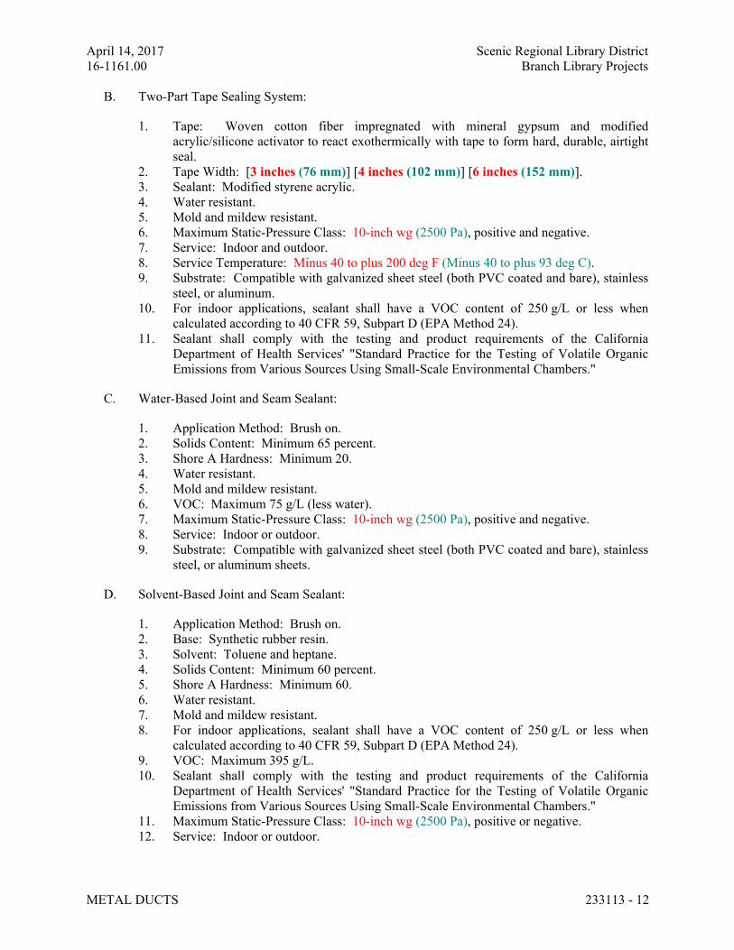
April 14, 2017 Scenic Regional Library District
16-1161.00 Branch Library Projects
METAL DUCTS 233113 - 12
B. Two-Part Tape Sealing System:
1. Tape: Woven cotton fiber impregnated with mineral gypsum and modified
acrylic/silicone activator to react exothermically with tape to form hard, durable, airtight
seal.
2. Tape Width: [3 inches (76 mm)] [4 inches (102 mm)] [6 inches (152 mm)].
3. Sealant: Modified styrene acrylic.
4. Water resistant.
5. Mold and mildew resistant.
6. Maximum Static-Pressure Class: 10-inch wg (2500 Pa), positive and negative.
7. Service: Indoor and outdoor.
8. Service Temperature: Minus 40 to plus 200 deg F (Minus 40 to plus 93 deg C).
9. Substrate: Compatible with galvanized sheet steel (both PVC coated and bare), stainless
steel, or aluminum.
10. For indoor applications, sealant shall have a VOC content of 250 g/L or less when
calculated according to 40 CFR 59, Subpart D (EPA Method 24).
11. Sealant shall comply with the testing and product requirements of the California
Department of Health Services' "Standard Practice for the Testing of Volatile Organic
Emissions from Various Sources Using Small-Scale Environmental Chambers."
C. Water-Based Joint and Seam Sealant:
1. Application Method: Brush on.
2. Solids Content: Minimum 65 percent.
3. Shore A Hardness: Minimum 20.
4. Water resistant.
5. Mold and mildew resistant.
6. VOC: Maximum 75 g/L (less water).
7. Maximum Static-Pressure Class: 10-inch wg (2500 Pa), positive and negative.
8. Service: Indoor or outdoor.
9. Substrate: Compatible with galvanized sheet steel (both PVC coated and bare), stainless
steel, or aluminum sheets.
D. Solvent-Based Joint and Seam Sealant:
1. Application Method: Brush on.
2. Base: Synthetic rubber resin.
3. Solvent: Toluene and heptane.
4. Solids Content: Minimum 60 percent.
5. Shore A Hardness: Minimum 60.
6. Water resistant.
7. Mold and mildew resistant.
8. For indoor applications, sealant shall have a VOC content of 250 g/L or less when
calculated according to 40 CFR 59, Subpart D (EPA Method 24).
9. VOC: Maximum 395 g/L.
10. Sealant shall comply with the testing and product requirements of the California
Department of Health Services' "Standard Practice for the Testing of Volatile Organic
Emissions from Various Sources Using Small-Scale Environmental Chambers."
11. Maximum Static-Pressure Class: 10-inch wg (2500 Pa), positive or negative.
12. Service: Indoor or outdoor.
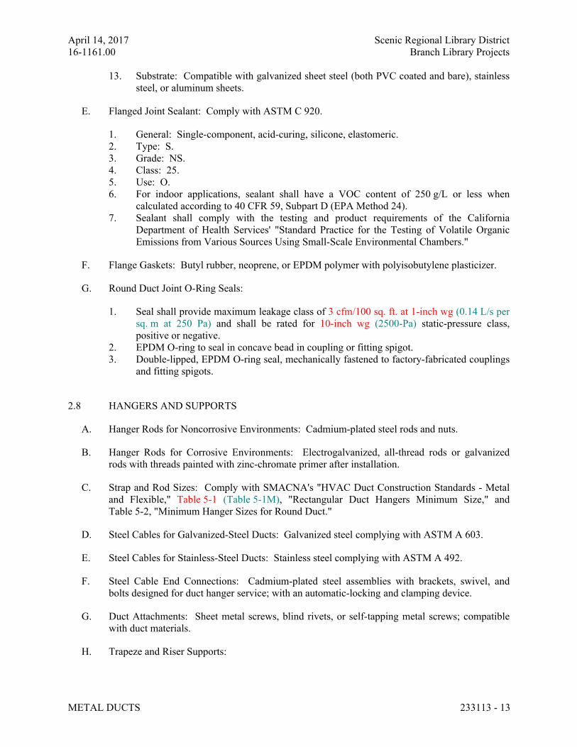
April 14, 2017 Scenic Regional Library District
16-1161.00 Branch Library Projects
METAL DUCTS 233113 - 13
13. Substrate: Compatible with galvanized sheet steel (both PVC coated and bare), stainless
steel, or aluminum sheets.
E. Flanged Joint Sealant: Comply with ASTM C 920.
1. General: Single-component, acid-curing, silicone, elastomeric.
2. Type: S.
3. Grade: NS.
4. Class: 25.
5. Use: O.
6. For indoor applications, sealant shall have a VOC content of 250 g/L or less when
calculated according to 40 CFR 59, Subpart D (EPA Method 24).
7. Sealant shall comply with the testing and product requirements of the California
Department of Health Services' "Standard Practice for the Testing of Volatile Organic
Emissions from Various Sources Using Small-Scale Environmental Chambers."
F. Flange Gaskets: Butyl rubber, neoprene, or EPDM polymer with polyisobutylene plasticizer.
G. Round Duct Joint O-Ring Seals:
1. Seal shall provide maximum leakage class of 3 cfm/100 sq. ft. at 1-inch wg (0.14 L/s per
sq. m at 250 Pa) and shall be rated for 10-inch wg (2500-Pa) static-pressure class,
positive or negative.
2. EPDM O-ring to seal in concave bead in coupling or fitting spigot.
3. Double-lipped, EPDM O-ring seal, mechanically fastened to factory-fabricated couplings
and fitting spigots.
2.8 HANGERS AND SUPPORTS
A. Hanger Rods for Noncorrosive Environments: Cadmium-plated steel rods and nuts.
B. Hanger Rods for Corrosive Environments: Electrogalvanized, all-thread rods or galvanized
rods with threads painted with zinc-chromate primer after installation.
C. Strap and Rod Sizes: Comply with SMACNA's "HVAC Duct Construction Standards - Metal
and Flexible," Table 5-1 (Table 5-1M), "Rectangular Duct Hangers Minimum Size," and
Table 5-2, "Minimum Hanger Sizes for Round Duct."
D. Steel Cables for Galvanized-Steel Ducts: Galvanized steel complying with ASTM A 603.
E. Steel Cables for Stainless-Steel Ducts: Stainless steel complying with ASTM A 492.
F. Steel Cable End Connections: Cadmium-plated steel assemblies with brackets, swivel, and
bolts designed for duct hanger service; with an automatic-locking and clamping device.
G. Duct Attachments: Sheet metal screws, blind rivets, or self-tapping metal screws; compatible
with duct materials.
H. Trapeze and Riser Supports:
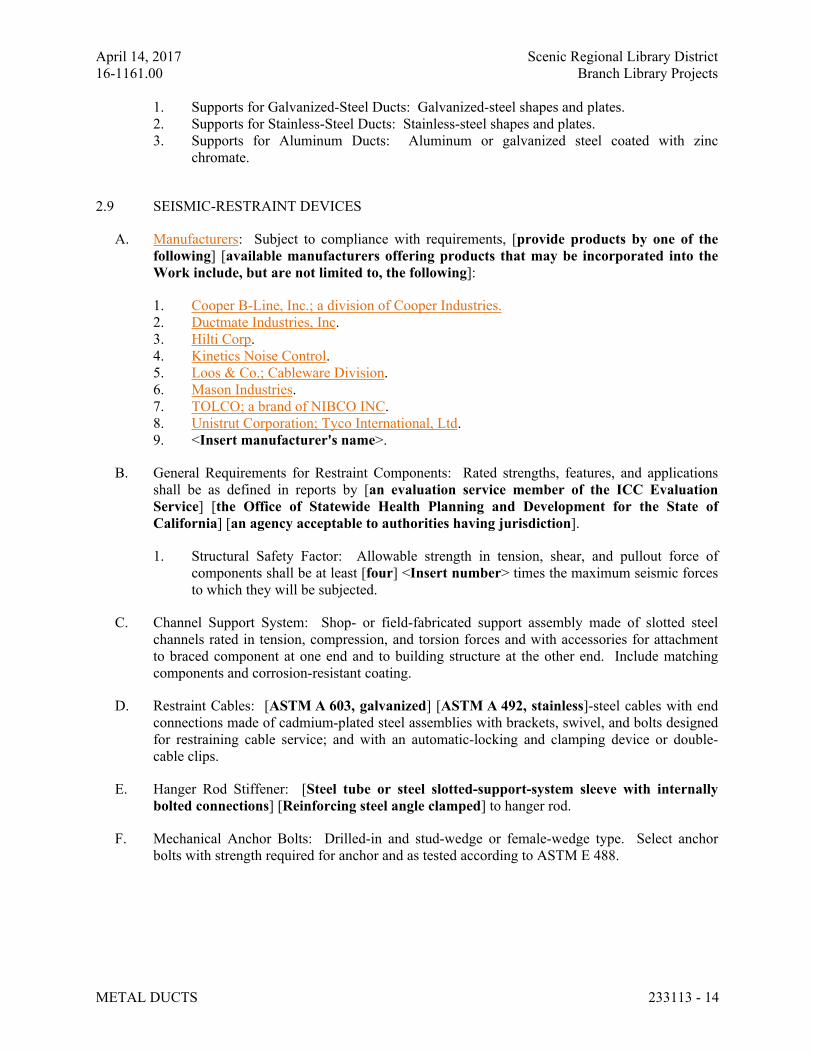
April 14, 2017 Scenic Regional Library District
16-1161.00 Branch Library Projects
METAL DUCTS 233113 - 14
1. Supports for Galvanized-Steel Ducts: Galvanized-steel shapes and plates.
2. Supports for Stainless-Steel Ducts: Stainless-steel shapes and plates.
3. Supports for Aluminum Ducts: Aluminum or galvanized steel coated with zinc
chromate.
2.9 SEISMIC-RESTRAINT DEVICES
A. Manufacturers: Subject to compliance with requirements, [provide products by one of the
following] [available manufacturers offering products that may be incorporated into the
Work include, but are not limited to, the following]:
1. Cooper B-Line, Inc.; a division of Cooper Industries.
2. Ductmate Industries, Inc.
3. Hilti Corp.
4. Kinetics Noise Control.
5. Loos & Co.; Cableware Division.
6. Mason Industries.
7. TOLCO; a brand of NIBCO INC.
8. Unistrut Corporation; Tyco International, Ltd.
9. <Insert manufacturer's name>.
B. General Requirements for Restraint Components: Rated strengths, features, and applications
shall be as defined in reports by [an evaluation service member of the ICC Evaluation
Service] [the Office of Statewide Health Planning and Development for the State of
California] [an agency acceptable to authorities having jurisdiction].
1. Structural Safety Factor: Allowable strength in tension, shear, and pullout force of
components shall be at least [four] <Insert number> times the maximum seismic forces
to which they will be subjected.
C. Channel Support System: Shop- or field-fabricated support assembly made of slotted steel
channels rated in tension, compression, and torsion forces and with accessories for attachment
to braced component at one end and to building structure at the other end. Include matching
components and corrosion-resistant coating.
D. Restraint Cables: [ASTM A 603, galvanized] [ASTM A 492, stainless]-steel cables with end
connections made of cadmium-plated steel assemblies with brackets, swivel, and bolts designed
for restraining cable service; and with an automatic-locking and clamping device or double-
cable clips.
E. Hanger Rod Stiffener: [Steel tube or steel slotted-support-system sleeve with internally
bolted connections] [Reinforcing steel angle clamped] to hanger rod.
F. Mechanical Anchor Bolts: Drilled-in and stud-wedge or female-wedge type. Select anchor
bolts with strength required for anchor and as tested according to ASTM E 488.
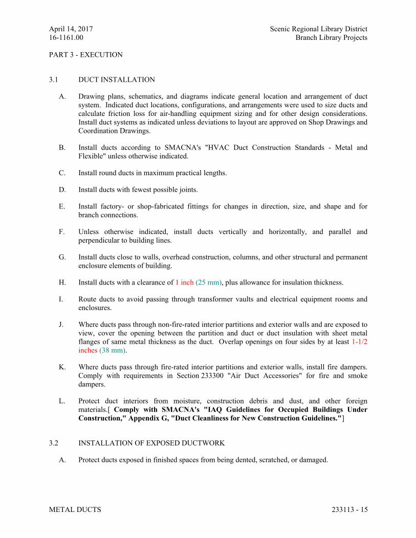
April 14, 2017 Scenic Regional Library District
16-1161.00 Branch Library Projects
METAL DUCTS 233113 - 15
PART 3 - EXECUTION
3.1 DUCT INSTALLATION
A. Drawing plans, schematics, and diagrams indicate general location and arrangement of duct
system. Indicated duct locations, configurations, and arrangements were used to size ducts and
calculate friction loss for air-handling equipment sizing and for other design considerations.
Install duct systems as indicated unless deviations to layout are approved on Shop Drawings and
Coordination Drawings.
B. Install ducts according to SMACNA's "HVAC Duct Construction Standards - Metal and
Flexible" unless otherwise indicated.
C. Install round ducts in maximum practical lengths.
D. Install ducts with fewest possible joints.
E. Install factory- or shop-fabricated fittings for changes in direction, size, and shape and for
branch connections.
F. Unless otherwise indicated, install ducts vertically and horizontally, and parallel and
perpendicular to building lines.
G. Install ducts close to walls, overhead construction, columns, and other structural and permanent
enclosure elements of building.
H. Install ducts with a clearance of 1 inch (25 mm), plus allowance for insulation thickness.
I. Route ducts to avoid passing through transformer vaults and electrical equipment rooms and
enclosures.
J. Where ducts pass through non-fire-rated interior partitions and exterior walls and are exposed to
view, cover the opening between the partition and duct or duct insulation with sheet metal
flanges of same metal thickness as the duct. Overlap openings on four sides by at least 1-1/2
inches (38 mm).
K. Where ducts pass through fire-rated interior partitions and exterior walls, install fire dampers.
Comply with requirements in Section 233300 "Air Duct Accessories" for fire and smoke
dampers.
L. Protect duct interiors from moisture, construction debris and dust, and other foreign
materials.[ Comply with SMACNA's "IAQ Guidelines for Occupied Buildings Under
Construction," Appendix G, "Duct Cleanliness for New Construction Guidelines."]
3.2 INSTALLATION OF EXPOSED DUCTWORK
A. Protect ducts exposed in finished spaces from being dented, scratched, or damaged.
April 14, 2017 Scenic Regional Library District
16-1161.00 Branch Library Projects
METAL DUCTS 233113 - 16
B. Trim duct sealants flush with metal. Create a smooth and uniform exposed bead. Do not use
two-part tape sealing system.
C. Grind welds to provide smooth surface free of burrs, sharp edges, and weld splatter. When
welding stainless steel with a No. 3 or 4 finish, grind the welds flush, polish the exposed welds,
and treat the welds to remove discoloration caused by welding.
D. Maintain consistency, symmetry, and uniformity in the arrangement and fabrication of fittings,
hangers and supports, duct accessories, and air outlets.
E. Repair or replace damaged sections and finished work that does not comply with these
requirements.
3.3 ADDITIONAL INSTALLATION REQUIREMENTS FOR COMMERCIAL KITCHEN
HOOD EXHAUST DUCT
A. Install commercial kitchen hood exhaust ducts without dips and traps that may hold grease, and
sloped a minimum of 2 percent to drain grease back to the hood.
B. Install fire-rated access panel assemblies at each change in direction and at maximum intervals
of [20 feet (6 m)] [12 feet (3.7 m)] <Insert dimension> in horizontal ducts, and at every floor
for vertical ducts, or as indicated on Drawings. Locate access panel on top or sides of duct a
minimum of 1-1/2 inches (38 mm) from bottom of duct.
C. Do not penetrate fire-rated assemblies except as allowed by applicable building codes and
authorities having jurisdiction.
3.4 DUCT SEALING
A. Seal ducts for duct static-pressure, seal classes, and leakage classes specified in "Duct
Schedule" Article according to SMACNA's "HVAC Duct Construction Standards - Metal and
Flexible."
B. Seal ducts to the following seal classes according to SMACNA's "HVAC Duct Construction
Standards - Metal and Flexible":
1. Comply with SMACNA's "HVAC Duct Construction Standards - Metal and Flexible."
2. Outdoor, Supply-Air Ducts: Seal Class A.
3. Outdoor, Exhaust Ducts: Seal Class C.
4. Outdoor, Return-Air Ducts: Seal Class C.
5. Unconditioned Space, Supply-Air Ducts in Pressure Classes 2-Inch wg (500 Pa) and
Lower: Seal Class B.
6. Unconditioned Space, Supply-Air Ducts in Pressure Classes Higher Than 2-Inch wg (500
Pa): Seal Class A.
7. Unconditioned Space, Exhaust Ducts: Seal Class C.
8. Unconditioned Space, Return-Air Ducts: Seal Class B.
9. Conditioned Space, Supply-Air Ducts in Pressure Classes 2-Inch wg (500 Pa) and Lower:
Seal Class C.
April 14, 2017 Scenic Regional Library District
16-1161.00 Branch Library Projects
METAL DUCTS 233113 - 17
10. Conditioned Space, Supply-Air Ducts in Pressure Classes Higher Than 2-Inch wg (500
Pa): Seal Class B.
11. Conditioned Space, Exhaust Ducts: Seal Class B.
12. Conditioned Space, Return-Air Ducts: Seal Class C.
3.5 HANGER AND SUPPORT INSTALLATION
A. Comply with SMACNA's "HVAC Duct Construction Standards - Metal and Flexible,"
Chapter 5, "Hangers and Supports."
B. Building Attachments: Concrete inserts, powder-actuated fasteners, or structural-steel fasteners
appropriate for construction materials to which hangers are being attached.
1. Where practical, install concrete inserts before placing concrete.
2. Install powder-actuated concrete fasteners after concrete is placed and completely cured.
3. Use powder-actuated concrete fasteners for standard-weight aggregate concretes or for
slabs more than 4 inches (100 mm) thick.
4. Do not use powder-actuated concrete fasteners for lightweight-aggregate concretes or for
slabs less than 4 inches (100 mm) thick.
5. Do not use powder-actuated concrete fasteners for seismic restraints.
C. Hanger Spacing: Comply with SMACNA's "HVAC Duct Construction Standards - Metal and
Flexible," Table 5-1 (Table 5-1M), "Rectangular Duct Hangers Minimum Size," and Table 5-2,
"Minimum Hanger Sizes for Round Duct," for maximum hanger spacing; install hangers and
supports within 24 inches (610 mm) of each elbow and within 48 inches (1200 mm) of each
branch intersection.
D. Hangers Exposed to View: Threaded rod and angle or channel supports.
E. Support vertical ducts with steel angles or channel secured to the sides of the duct with welds,
bolts, sheet metal screws, or blind rivets; support at each floor and at a maximum intervals of 16
feet (5 m).
F. Install upper attachments to structures. Select and size upper attachments with pull-out, tension,
and shear capacities appropriate for supported loads and building materials where used.
3.6 SEISMIC-RESTRAINT-DEVICE INSTALLATION
A. Install ducts with hangers and braces designed to support the duct and to restrain against seismic
forces required by applicable building codes. Comply with [SMACNA's "Seismic Restraint
Manual: Guidelines for Mechanical Systems."] [ASCE/SEI 7.]
1. Space lateral supports a maximum of [40 feet (12 m)] <Insert dimension> o.c., and
longitudinal supports a maximum of [80 feet (24 m)] <Insert dimension> o.c.
2. Brace a change of direction longer than 12 feet (3.7 m).
B. Select seismic-restraint devices with capacities adequate to carry present and future static and
seismic loads.
April 14, 2017 Scenic Regional Library District
16-1161.00 Branch Library Projects
METAL DUCTS 233113 - 18
C. Install cables so they do not bend across edges of adjacent equipment or building structure.
D. Install cable restraints on ducts that are suspended with vibration isolators.
E. Install seismic-restraint devices using methods approved by [an evaluation service member of
the ICC Evaluation Service] [the Office of Statewide Health Planning and Development
for the State of California] [an agency acceptable to authorities having jurisdiction].
F. Attachment to Structure: If specific attachment is not indicated, anchor bracing and restraints to
structure, to flanges of beams, to upper truss chords of bar joists, or to concrete members.
G. Drilling for and Setting Anchors:
1. Identify position of reinforcing steel and other embedded items prior to drilling holes for
anchors. Do not damage existing reinforcement or embedded items during drilling.
Notify the Architect if reinforcing steel or other embedded items are encountered during
drilling. Locate and avoid prestressed tendons, electrical and telecommunications
conduit, and gas lines.
2. Do not drill holes in concrete or masonry until concrete, mortar, or grout has achieved
full design strength.
3. Wedge Anchors: Protect threads from damage during anchor installation. Heavy-duty
sleeve anchors shall be installed with sleeve fully engaged in the structural element to
which anchor is to be fastened.
4. Set anchors to manufacturer's recommended torque, using a torque wrench.
5. Install zinc-coated steel anchors for interior applications and stainless-steel anchors for
applications exposed to weather.
3.7 CONNECTIONS
A. Make connections to equipment with flexible connectors complying with Section 233300 "Air
Duct Accessories."
B. Comply with SMACNA's "HVAC Duct Construction Standards - Metal and Flexible" for
branch, outlet and inlet, and terminal unit connections.
3.8 PAINTING
A. Paint interior of metal ducts that are visible through registers and grilles and that do not have
duct liner. Apply one coat of flat, black, latex paint over a compatible galvanized-steel primer.
Paint materials and application requirements are specified in Section 099113 "Exterior Painting"
and Section 099123 "Interior Painting."
3.9 FIELD QUALITY CONTROL
A. Perform tests and inspections.
B. Leakage Tests:
April 14, 2017 Scenic Regional Library District
16-1161.00 Branch Library Projects
METAL DUCTS 233113 - 19
1. Comply with SMACNA's "HVAC Air Duct Leakage Test Manual." Submit a test report
for each test.
2. Test the following systems:
a. Ducts with a Pressure Class Higher Than 3-Inch wg (750 Pa): Test representative
duct sections[, selected by Architect from sections installed,] totaling no less
than 25 percent of total installed duct area for each designated pressure class.
b. Supply Ducts with a Pressure Class of [2-Inch wg (500 Pa)] [3-Inch wg (750 Pa)]
[4-Inch wg (1000 Pa)] <Insert value> or Higher: Test representative duct
sections[, selected by Architect from sections installed,] totaling no less than
[50] [100] <Insert value> percent of total installed duct area for each designated
pressure class.
c. Return Ducts with a Pressure Class of [2-Inch wg (500 Pa)] [3-Inch wg (750 Pa)]
[4-Inch wg (1000 Pa)] <Insert value> or Higher: Test representative duct
sections[, selected by Architect from sections installed,] totaling no less than
[50] [100] <Insert value> percent of total installed duct area for each designated
pressure class.
d. Exhaust Ducts with a Pressure Class of [2-Inch wg (500 Pa)] [3-Inch wg (750
Pa)] [4-Inch wg (1000 Pa)] <Insert value> or Higher: Test representative duct
sections[, selected by Architect from sections installed,] totaling no less than
[50] [100] <Insert value> percent of total installed duct area for each designated
pressure class.
e. Outdoor Air Ducts with a Pressure Class of [2-Inch wg (500 Pa)] [3-Inch wg (750
Pa)] [4-Inch wg (1000 Pa)] <Insert value> or Higher: Test representative duct
sections[, selected by Architect from sections installed,] totaling no less than
[50] [100] <Insert value> percent of total installed duct area for each designated
pressure class.
3. Disassemble, reassemble, and seal segments of systems to accommodate leakage testing
and for compliance with test requirements.
4. Test for leaks before applying external insulation.
5. Conduct tests at static pressures equal to maximum design pressure of system or section
being tested. If static-pressure classes are not indicated, test system at maximum system
design pressure. Do not pressurize systems above maximum design operating pressure.
6. Give [seven] <Insert number> days' advance notice for testing.
C. Duct System Cleanliness Tests:
1. Visually inspect duct system to ensure that no visible contaminants are present.
2. Test sections of metal duct system, chosen randomly by Owner, for cleanliness according
to "Vacuum Test" in NADCA ACR, "Assessment, Cleaning and Restoration of HVAC
Systems."
a. Acceptable Cleanliness Level: Net weight of debris collected on the filter media
shall not exceed 0.75 mg/100 sq. cm.
D. Duct system will be considered defective if it does not pass tests and inspections.
E. Prepare test and inspection reports.
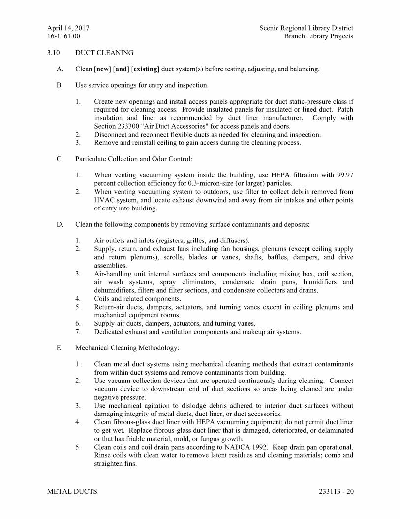
April 14, 2017 Scenic Regional Library District
16-1161.00 Branch Library Projects
METAL DUCTS 233113 - 20
3.10 DUCT CLEANING
A. Clean [new] [and] [existing] duct system(s) before testing, adjusting, and balancing.
B. Use service openings for entry and inspection.
1. Create new openings and install access panels appropriate for duct static-pressure class if
required for cleaning access. Provide insulated panels for insulated or lined duct. Patch
insulation and liner as recommended by duct liner manufacturer. Comply with
Section 233300 "Air Duct Accessories" for access panels and doors.
2. Disconnect and reconnect flexible ducts as needed for cleaning and inspection.
3. Remove and reinstall ceiling to gain access during the cleaning process.
C. Particulate Collection and Odor Control:
1. When venting vacuuming system inside the building, use HEPA filtration with 99.97
percent collection efficiency for 0.3-micron-size (or larger) particles.
2. When venting vacuuming system to outdoors, use filter to collect debris removed from
HVAC system, and locate exhaust downwind and away from air intakes and other points
of entry into building.
D. Clean the following components by removing surface contaminants and deposits:
1. Air outlets and inlets (registers, grilles, and diffusers).
2. Supply, return, and exhaust fans including fan housings, plenums (except ceiling supply
and return plenums), scrolls, blades or vanes, shafts, baffles, dampers, and drive
assemblies.
3. Air-handling unit internal surfaces and components including mixing box, coil section,
air wash systems, spray eliminators, condensate drain pans, humidifiers and
dehumidifiers, filters and filter sections, and condensate collectors and drains.
4. Coils and related components.
5. Return-air ducts, dampers, actuators, and turning vanes except in ceiling plenums and
mechanical equipment rooms.
6. Supply-air ducts, dampers, actuators, and turning vanes.
7. Dedicated exhaust and ventilation components and makeup air systems.
E. Mechanical Cleaning Methodology:
1. Clean metal duct systems using mechanical cleaning methods that extract contaminants
from within duct systems and remove contaminants from building.
2. Use vacuum-collection devices that are operated continuously during cleaning. Connect
vacuum device to downstream end of duct sections so areas being cleaned are under
negative pressure.
3. Use mechanical agitation to dislodge debris adhered to interior duct surfaces without
damaging integrity of metal ducts, duct liner, or duct accessories.
4. Clean fibrous-glass duct liner with HEPA vacuuming equipment; do not permit duct liner
to get wet. Replace fibrous-glass duct liner that is damaged, deteriorated, or delaminated
or that has friable material, mold, or fungus growth.
5. Clean coils and coil drain pans according to NADCA 1992. Keep drain pan operational.
Rinse coils with clean water to remove latent residues and cleaning materials; comb and
straighten fins.
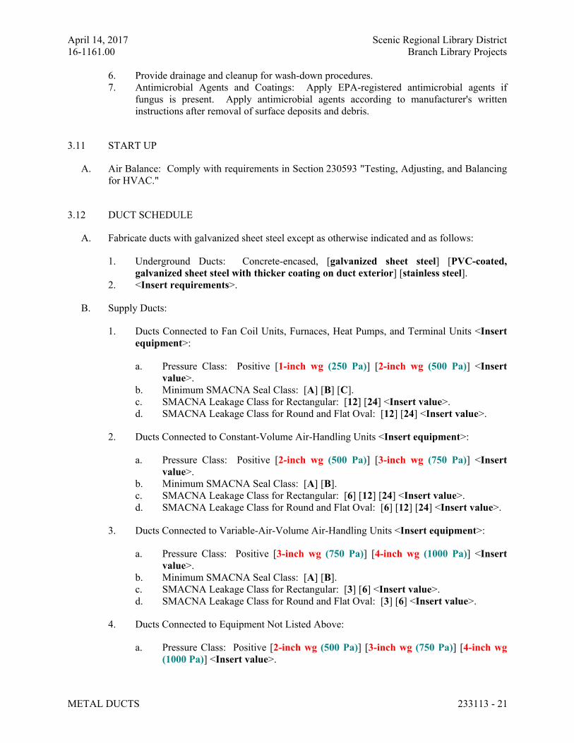
April 14, 2017 Scenic Regional Library District
16-1161.00 Branch Library Projects
METAL DUCTS 233113 - 21
6. Provide drainage and cleanup for wash-down procedures.
7. Antimicrobial Agents and Coatings: Apply EPA-registered antimicrobial agents if
fungus is present. Apply antimicrobial agents according to manufacturer's written
instructions after removal of surface deposits and debris.
3.11 START UP
A. Air Balance: Comply with requirements in Section 230593 "Testing, Adjusting, and Balancing
for HVAC."
3.12 DUCT SCHEDULE
A. Fabricate ducts with galvanized sheet steel except as otherwise indicated and as follows:
1. Underground Ducts: Concrete-encased, [galvanized sheet steel] [PVC-coated,
galvanized sheet steel with thicker coating on duct exterior] [stainless steel].
2. <Insert requirements>.
B. Supply Ducts:
1. Ducts Connected to Fan Coil Units, Furnaces, Heat Pumps, and Terminal Units <Insert
equipment>:
a. Pressure Class: Positive [1-inch wg (250 Pa)] [2-inch wg (500 Pa)] <Insert
value>.
b. Minimum SMACNA Seal Class: [A] [B] [C].
c. SMACNA Leakage Class for Rectangular: [12] [24] <Insert value>.
d. SMACNA Leakage Class for Round and Flat Oval: [12] [24] <Insert value>.
2. Ducts Connected to Constant-Volume Air-Handling Units <Insert equipment>:
a. Pressure Class: Positive [2-inch wg (500 Pa)] [3-inch wg (750 Pa)] <Insert
value>.
b. Minimum SMACNA Seal Class: [A] [B].
c. SMACNA Leakage Class for Rectangular: [6] [12] [24] <Insert value>.
d. SMACNA Leakage Class for Round and Flat Oval: [6] [12] [24] <Insert value>.
3. Ducts Connected to Variable-Air-Volume Air-Handling Units <Insert equipment>:
a. Pressure Class: Positive [3-inch wg (750 Pa)] [4-inch wg (1000 Pa)] <Insert
value>.
b. Minimum SMACNA Seal Class: [A] [B].
c. SMACNA Leakage Class for Rectangular: [3] [6] <Insert value>.
d. SMACNA Leakage Class for Round and Flat Oval: [3] [6] <Insert value>.
4. Ducts Connected to Equipment Not Listed Above:
a. Pressure Class: Positive [2-inch wg (500 Pa)] [3-inch wg (750 Pa)] [4-inch wg
(1000 Pa)] <Insert value>.
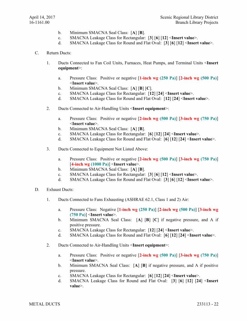
April 14, 2017 Scenic Regional Library District
16-1161.00 Branch Library Projects
METAL DUCTS 233113 - 22
b. Minimum SMACNA Seal Class: [A] [B].
c. SMACNA Leakage Class for Rectangular: [3] [6] [12] <Insert value>.
d. SMACNA Leakage Class for Round and Flat Oval: [3] [6] [12] <Insert value>.
C. Return Ducts:
1. Ducts Connected to Fan Coil Units, Furnaces, Heat Pumps, and Terminal Units <Insert
equipment>:
a. Pressure Class: Positive or negative [1-inch wg (250 Pa)] [2-inch wg (500 Pa)]
<Insert value>.
b. Minimum SMACNA Seal Class: [A] [B] [C].
c. SMACNA Leakage Class for Rectangular: [12] [24] <Insert value>.
d. SMACNA Leakage Class for Round and Flat Oval: [12] [24] <Insert value>.
2. Ducts Connected to Air-Handling Units <Insert equipment>:
a. Pressure Class: Positive or negative [2-inch wg (500 Pa)] [3-inch wg (750 Pa)]
<Insert value>.
b. Minimum SMACNA Seal Class: [A] [B].
c. SMACNA Leakage Class for Rectangular: [6] [12] [24] <Insert value>.
d. SMACNA Leakage Class for Round and Flat Oval: [6] [12] [24] <Insert value>.
3. Ducts Connected to Equipment Not Listed Above:
a. Pressure Class: Positive or negative [2-inch wg (500 Pa)] [3-inch wg (750 Pa)]
[4-inch wg (1000 Pa)] <Insert value>.
b. Minimum SMACNA Seal Class: [A] [B].
c. SMACNA Leakage Class for Rectangular: [3] [6] [12] <Insert value>.
d. SMACNA Leakage Class for Round and Flat Oval: [3] [6] [12] <Insert value>.
D. Exhaust Ducts:
1. Ducts Connected to Fans Exhausting (ASHRAE 62.1, Class 1 and 2) Air:
a. Pressure Class: Negative [1-inch wg (250 Pa)] [2-inch wg (500 Pa)] [3-inch wg
(750 Pa)] <Insert value>.
b. Minimum SMACNA Seal Class: [A] [B] [C] if negative pressure, and A if
positive pressure.
c. SMACNA Leakage Class for Rectangular: [12] [24] <Insert value>.
d. SMACNA Leakage Class for Round and Flat Oval: [6] [12] [24] <Insert value>.
2. Ducts Connected to Air-Handling Units <Insert equipment>:
a. Pressure Class: Positive or negative [2-inch wg (500 Pa)] [3-inch wg (750 Pa)]
<Insert value>.
b. Minimum SMACNA Seal Class: [A] [B] if negative pressure, and A if positive
pressure.
c. SMACNA Leakage Class for Rectangular: [6] [12] [24] <Insert value>.
d. SMACNA Leakage Class for Round and Flat Oval: [3] [6] [12] [24] <Insert
value>.
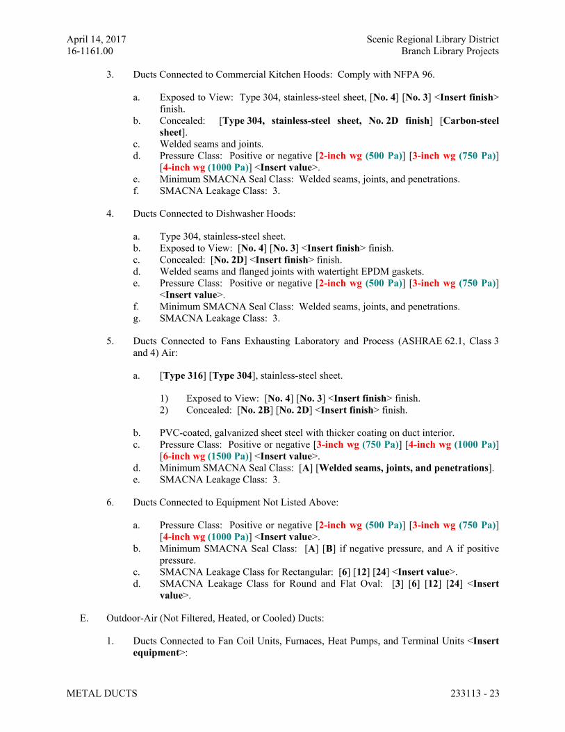
April 14, 2017 Scenic Regional Library District
16-1161.00 Branch Library Projects
METAL DUCTS 233113 - 23
3. Ducts Connected to Commercial Kitchen Hoods: Comply with NFPA 96.
a. Exposed to View: Type 304, stainless-steel sheet, [No. 4] [No. 3] <Insert finish>
finish.
b. Concealed: [Type 304, stainless-steel sheet, No. 2D finish] [Carbon-steel
sheet].
c. Welded seams and joints.
d. Pressure Class: Positive or negative [2-inch wg (500 Pa)] [3-inch wg (750 Pa)]
[4-inch wg (1000 Pa)] <Insert value>.
e. Minimum SMACNA Seal Class: Welded seams, joints, and penetrations.
f. SMACNA Leakage Class: 3.
4. Ducts Connected to Dishwasher Hoods:
a. Type 304, stainless-steel sheet.
b. Exposed to View: [No. 4] [No. 3] <Insert finish> finish.
c. Concealed: [No. 2D] <Insert finish> finish.
d. Welded seams and flanged joints with watertight EPDM gaskets.
e. Pressure Class: Positive or negative [2-inch wg (500 Pa)] [3-inch wg (750 Pa)]
<Insert value>.
f. Minimum SMACNA Seal Class: Welded seams, joints, and penetrations.
g. SMACNA Leakage Class: 3.
5. Ducts Connected to Fans Exhausting Laboratory and Process (ASHRAE 62.1, Class 3
and 4) Air:
a. [Type 316] [Type 304], stainless-steel sheet.
1) Exposed to View: [No. 4] [No. 3] <Insert finish> finish.
2) Concealed: [No. 2B] [No. 2D] <Insert finish> finish.
b. PVC-coated, galvanized sheet steel with thicker coating on duct interior.
c. Pressure Class: Positive or negative [3-inch wg (750 Pa)] [4-inch wg (1000 Pa)]
[6-inch wg (1500 Pa)] <Insert value>.
d. Minimum SMACNA Seal Class: [A] [Welded seams, joints, and penetrations].
e. SMACNA Leakage Class: 3.
6. Ducts Connected to Equipment Not Listed Above:
a. Pressure Class: Positive or negative [2-inch wg (500 Pa)] [3-inch wg (750 Pa)]
[4-inch wg (1000 Pa)] <Insert value>.
b. Minimum SMACNA Seal Class: [A] [B] if negative pressure, and A if positive
pressure.
c. SMACNA Leakage Class for Rectangular: [6] [12] [24] <Insert value>.
d. SMACNA Leakage Class for Round and Flat Oval: [3] [6] [12] [24] <Insert
value>.
E. Outdoor-Air (Not Filtered, Heated, or Cooled) Ducts:
1. Ducts Connected to Fan Coil Units, Furnaces, Heat Pumps, and Terminal Units <Insert
equipment>:
April 14, 2017 Scenic Regional Library District
16-1161.00 Branch Library Projects
METAL DUCTS 233113 - 24
a. Pressure Class: Positive or negative [1-inch wg (250 Pa)] [2-inch wg (500 Pa)]
<Insert value>.
b. Minimum SMACNA Seal Class: [A] [B] [C].
c. SMACNA Leakage Class for Rectangular: [12] [24] <Insert value>.
d. SMACNA Leakage Class for Round and Flat Oval: [6] [12] [24] <Insert value>.
2. Ducts Connected to Air-Handling Units <Insert equipment>:
a. Pressure Class: Positive or negative [2-inch wg (500 Pa)] [3-inch wg (750 Pa)]
<Insert value>.
b. Minimum SMACNA Seal Class: [A] [B].
c. SMACNA Leakage Class for Rectangular: [6] [12] [24] <Insert value>.
d. SMACNA Leakage Class for Round and Flat Oval: [3] [6] [12] [24] <Insert
value>.
3. Ducts Connected to Equipment Not Listed Above:
a. Pressure Class: Positive or negative [2-inch wg (500 Pa)] [3-inch wg (750 Pa)]
[4-inch wg (1000 Pa)] <Insert value>.
b. Minimum SMACNA Seal Class: [A] [B].
c. SMACNA Leakage Class for Rectangular: [3] [6] [12] <Insert value>.
d. SMACNA Leakage Class for Round and Flat Oval: [3] [6] [12] <Insert value>.
F. Intermediate Reinforcement:
1. Galvanized-Steel Ducts: [Galvanized steel] [Carbon steel coated with zinc-chromate
primer] [Galvanized steel or carbon steel coated with zinc-chromate primer].
2. PVC-Coated Ducts:
a. Exposed to Airstream: Match duct material.
b. Not Exposed to Airstream: [Galvanized] [Match duct material].
3. Stainless-Steel Ducts:
a. Exposed to Airstream: Match duct material.
b. Not Exposed to Airstream: [Galvanized] [Match duct material].
4. Aluminum Ducts: [Aluminum][or galvanized sheet steel coated with zinc chromate].
G. Liner:
1. Supply Air Ducts: [Fibrous glass, Type I] [Flexible elastomeric] [Natural fiber], [1
inch (25 mm)] [1-1/2 inches (38 mm)] [2 inches (51 mm)] <Insert thickness> thick.
2. Return Air Ducts: [Fibrous glass, Type I] [Flexible elastomeric] [Natural fiber], [1
inch (25 mm)] [1-1/2 inches (38 mm)] [2 inches (51 mm)] <Insert thickness> thick.
3. Exhaust Air Ducts: [Fibrous glass, Type I] [Flexible elastomeric] [Natural fiber], [1
inch (25 mm)] <Insert thickness> thick.
4. Supply Fan Plenums: [Fibrous glass, Type II] [Flexible elastomeric] [Natural fiber],
[1 inch (25 mm)] [1-1/2 inches (38 mm)] [2 inches (51 mm)] <Insert thickness> thick.
5. Return- and Exhaust-Fan Plenums: [Fibrous glass, Type II] [Flexible elastomeric]
[Natural fiber], [2 inches (51 mm)] <Insert thickness> thick.
April 14, 2017 Scenic Regional Library District
16-1161.00 Branch Library Projects
METAL DUCTS 233113 - 25
6. Transfer Ducts: [Fibrous glass, Type I] [Flexible elastomeric] [Natural fiber], [1 inch
(25 mm)] [1-1/2 inches (38 mm)] [2 inches (51 mm)] <Insert thickness> thick.
H. Double-Wall Duct Interstitial Insulation:
1. Supply Air Ducts: [1 inch (25 mm)] [1-1/2 inches (38 mm)] [2 inches (51 mm)]
<Insert thickness> thick.
2. Return Air Ducts: [1 inch (25 mm)] [1-1/2 inches (38 mm)] [2 inches (51 mm)]
<Insert thickness> thick.
3. Exhaust Air Ducts: [1 inch (25 mm)] [1-1/2 inches (38 mm)] [2 inches (51 mm)]
<Insert thickness> thick.
I. Elbow Configuration:
1. Rectangular Duct: Comply with SMACNA's "HVAC Duct Construction Standards -
Metal and Flexible," Figure 4-2, "Rectangular Elbows."
a. Velocity 1000 fpm (5 m/s) or Lower:
1) Radius Type RE 1 with minimum 0.5 radius-to-diameter ratio.
2) Mitered Type RE 4 without vanes.
b. Velocity 1000 to 1500 fpm (5 to 7.6 m/s):
1) Radius Type RE 1 with minimum 1.0 radius-to-diameter ratio.
2) Radius Type RE 3 with minimum 0.5 radius-to-diameter ratio and two
vanes.
3) Mitered Type RE 2 with vanes complying with SMACNA's "HVAC Duct
Construction Standards - Metal and Flexible," Figure 4-3, "Vanes and Vane
Runners," and Figure 4-4, "Vane Support in Elbows."
c. Velocity 1500 fpm (7.6 m/s) or Higher:
1) Radius Type RE 1 with minimum 1.5 radius-to-diameter ratio.
2) Radius Type RE 3 with minimum 1.0 radius-to-diameter ratio and two
vanes.
3) Mitered Type RE 2 with vanes complying with SMACNA's "HVAC Duct
Construction Standards - Metal and Flexible," Figure 4-3, "Vanes and Vane
Runners," and Figure 4-4, "Vane Support in Elbows."
2. Rectangular Duct: Comply with SMACNA's "HVAC Duct Construction Standards -
Metal and Flexible," Figure 4-2, "Rectangular Elbows."
a. Radius Type RE 1 with minimum 1.5 radius-to-diameter ratio.
b. Radius Type RE 3 with minimum 1.0 radius-to-diameter ratio and two vanes.
c. Mitered Type RE 2 with vanes complying with SMACNA's "HVAC Duct
Construction Standards - Metal and Flexible," Figure 4-3, "Vanes and Vane
Runners," and Figure 4-4, "Vane Support in Elbows."
3. Round Duct: Comply with SMACNA's "HVAC Duct Construction Standards - Metal
and Flexible," Figure 3-4, "Round Duct Elbows."

April 14, 2017 Scenic Regional Library District
16-1161.00 Branch Library Projects
METAL DUCTS 233113 - 26
a. Minimum Radius-to-Diameter Ratio and Elbow Segments: Comply with
SMACNA's "HVAC Duct Construction Standards - Metal and Flexible," Table 3-
1, "Mitered Elbows." Elbows with less than 90-degree change of direction have
proportionately fewer segments.
1) Velocity 1000 fpm (5 m/s) or Lower: 0.5 radius-to-diameter ratio and three
segments for 90-degree elbow.
2) Velocity 1000 to 1500 fpm (5 to 7.6 m/s): 1.0 radius-to-diameter ratio and
four segments for 90-degree elbow.
3) Velocity 1500 fpm (7.6 m/s) or Higher: 1.5 radius-to-diameter ratio and
five segments for 90-degree elbow.
4) Radius-to Diameter Ratio: 1.5.
b. Round Elbows, [12 Inches (305 mm)] <Insert dimension> and Smaller in
Diameter: Stamped or pleated.
c. Round Elbows, [14 Inches (356 mm)] <Insert dimension> and Larger in
Diameter: [Standing seam] [Welded].
J. Branch Configuration:
1. Rectangular Duct: Comply with SMACNA's "HVAC Duct Construction Standards -
Metal and Flexible," Figure 4-6, "Branch Connection."
a. Rectangular Main to Rectangular Branch: 45-degree entry.
b. Rectangular Main to Round Branch: Spin in.
2. Round and Flat Oval: Comply with SMACNA's "HVAC Duct Construction Standards -
Metal and Flexible," Figure 3-5, "90 Degree Tees and Laterals," and Figure 3-6, "Conical
Tees." Saddle taps are permitted in existing duct.
a. Velocity 1000 fpm (5 m/s) or Lower: 90-degree tap.
b. Velocity 1000 to 1500 fpm (5 to 7.6 m/s): Conical tap.
c. Velocity 1500 fpm (7.6 m/s) or Higher: 45-degree lateral.
END OF SECTION 233113
April 14, 2017 Scenic Regional Library District
16-1161.00 Branch Library Projects
AIR DUCT ACCESSORIES 233300 - 1
SECTION 233300 - AIR DUCT ACCESSORIES
ALL LIBRARIES
PART 1 - GENERAL
1.1 RELATED DOCUMENTS
A. Drawings and general provisions of the Contract, including General and Supplementary
Conditions and Division 01 Specification Sections, apply to this Section.
1.2 SUMMARY
A. Section Includes:
1. Backdraft and pressure relief dampers.
2. Barometric relief dampers.
3. Manual volume dampers.
4. Turning vanes.
5. Duct-mounted access doors.
6. Flexible connectors.
7. Flexible ducts.
8. Duct accessory hardware.
B. Related Requirements:
1. Section 233723 "HVAC Gravity Ventilators" for roof-mounted ventilator caps.
2. Section 283111 "Digital, Addressable Fire-Alarm System" for duct-mounted fire and
smoke detectors.
1.3 ACTION SUBMITTALS
A. Product Data: For each type of product.
1. For duct silencers, include pressure drop and dynamic insertion loss data. Include
breakout noise calculations for high transmission loss casings.
B. Shop Drawings: For duct accessories. Include plans, elevations, sections, details and
attachments to other work.
1. Detail duct accessories fabrication and installation in ducts and other construction.
Include dimensions, weights, loads, and required clearances; and method of field
assembly into duct systems and other construction. Include the following:
a. Special fittings.
b. Manual volume damper installations.
April 14, 2017 Scenic Regional Library District
16-1161.00 Branch Library Projects
AIR DUCT ACCESSORIES 233300 - 2
c. Control-damper installations.
d. Fire-damper, smoke-damper, combination fire- and smoke-damper, ceiling, and
corridor damper installations, including sleeves; and duct-mounted access doors
and remote damper operators.
e. Wiring Diagrams: For power, signal, and control wiring.
1.4 INFORMATIONAL SUBMITTALS
A. Coordination Drawings: Reflected ceiling plans, drawn to scale, on which ceiling-mounted
access panels and access doors required for access to duct accessories are shown and
coordinated with each other, using input from Installers of the items involved.
B. Source quality-control reports.
1.5 CLOSEOUT SUBMITTALS
A. Operation and Maintenance Data: For air duct accessories to include in operation and
maintenance manuals.
1.6 MAINTENANCE MATERIAL SUBMITTALS
A. Furnish extra materials that match products installed and that are packaged with protective
covering for storage and identified with labels describing contents.
1. Fusible Links: Furnish quantity equal to 10 percent of amount installed.
PART 2 - PRODUCTS
2.1 ASSEMBLY DESCRIPTION
A. Comply with NFPA 90A, "Installation of Air Conditioning and Ventilating Systems," and with
NFPA 90B, "Installation of Warm Air Heating and Air Conditioning Systems."
B. Comply with SMACNA's "HVAC Duct Construction Standards - Metal and Flexible" for
acceptable materials, material thicknesses, and duct construction methods unless otherwise
indicated. Sheet metal materials shall be free of pitting, seam marks, roller marks, stains,
discolorations, and other imperfections.
2.2 MATERIALS
A. Galvanized Sheet Steel: Comply with ASTM A 653/A 653M.
1. Galvanized Coating Designation: G60.
2. Exposed-Surface Finish: Mill phosphatized.
Comment [dl1]: G60 is what is typically
used. G90 is twice as thick as G60. Use
G90 if the ductwork could be potentially
exposed to high humidity and aluminum
or stainless steel are not called for. 10-28-
14
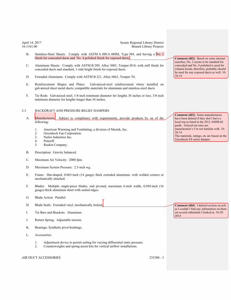
April 14, 2017 Scenic Regional Library District
16-1161.00 Branch Library Projects
AIR DUCT ACCESSORIES 233300 - 3
B. Stainless-Steel Sheets: Comply with ASTM A 480/A 480M, Type 304, and having a No. 2
finish for concealed ducts and No. 4 polished finish for exposed ducts.
C. Aluminum Sheets: Comply with ASTM B 209, Alloy 3003, Temper H14; with mill finish for
concealed ducts and standard, 1-side bright finish for exposed ducts.
D. Extruded Aluminum: Comply with ASTM B 221, Alloy 6063, Temper T6.
E. Reinforcement Shapes and Plates: Galvanized-steel reinforcement where installed on
galvanized sheet metal ducts; compatible materials for aluminum and stainless-steel ducts.
F. Tie Rods: Galvanized steel, 1/4-inch minimum diameter for lengths 36 inches or less; 3/8-inch
minimum diameter for lengths longer than 36 inches.
2.3 BACKDRAFT AND PRESSURE RELIEF DAMPERS
A. Manufacturers: Subject to compliance with requirements, provide products by on of the
following:
1. American Warming and Ventilating; a division of Mestek, Inc.
2. Greenheck Fan Corporation.
3. Nailor Industries Inc.
4. Pottorff.
5. Ruskin Company.
B. Description: Gravity balanced.
C. Maximum Air Velocity: 2000 fpm.
D. Maximum System Pressure: 2.5-inch wg.
E. Frame: Hat-shaped, 0.063-inch (14 gauge) thick extruded aluminum, with welded corners or
mechanically attached.
F. Blades: Multiple single-piece blades, end pivoted, maximum 6-inch width, 0.050-inch (16
gauge)-thick aluminum sheet with sealed edges.
G. Blade Action: Parallel.
H. Blade Seals: Extruded vinyl, mechanically locked.
I. Tie Bars and Brackets: Aluminum.
J. Return Spring: Adjustable tension.
K. Bearings: Synthetic pivot bushings.
L. Accessories:
1. Adjustment device to permit setting for varying differential static pressure.
2. Counterweights and spring-assist kits for vertical airflow installations.
Comment [dl2]: Based on some internet
searches, No. 2 seems to be standard for
concealed and No. 4 polished is used for
exhaust hoods, therefore, probably should
be used for any exposed ducts as well. 10-
28-14
Comment [dl3]: Some manufacturers
have been deleted if they don’t have a
local rep as listed in the 2012 ASHRAE
guide. Grayed out ones are
manufacturer’s I’m not familiar with. 10-
28-14
The materials, ratings, etc are based on the
Greenheck ES series damper.
Comment [dl4]: I deleted section on acle
as I couldn’t find any information on them
on several submittals I looked at. 10-28-
2014
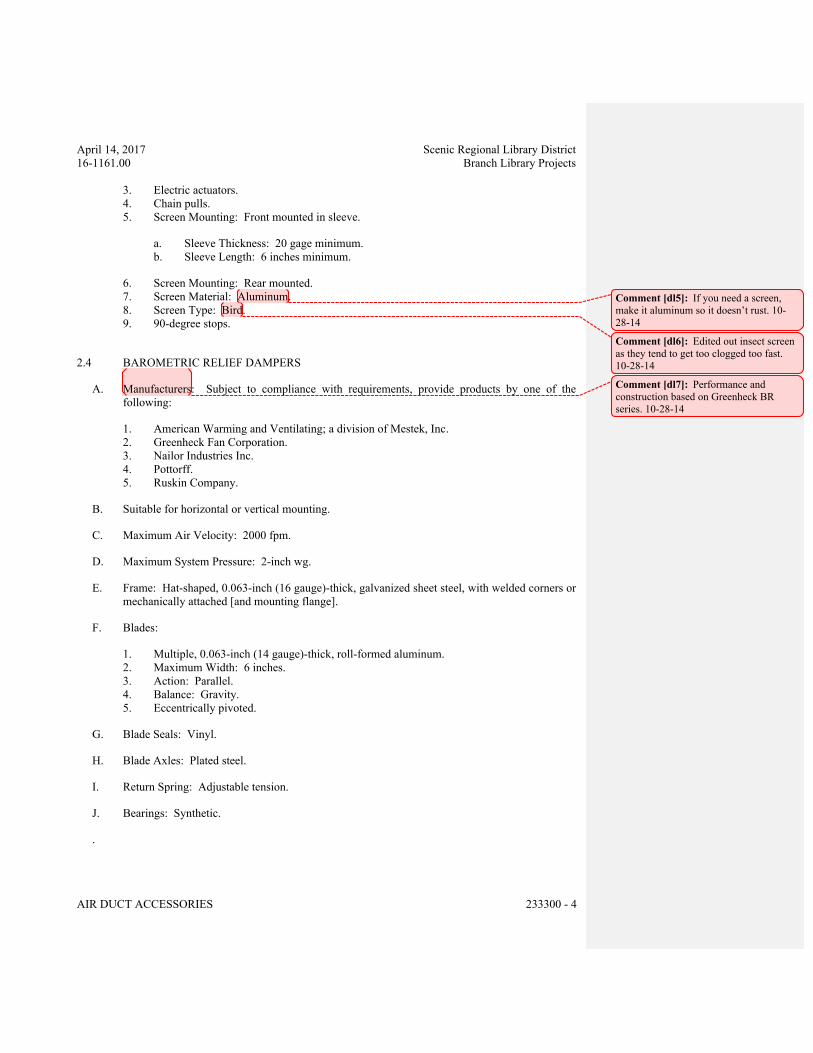
April 14, 2017 Scenic Regional Library District
16-1161.00 Branch Library Projects
AIR DUCT ACCESSORIES 233300 - 4
3. Electric actuators.
4. Chain pulls.
5. Screen Mounting: Front mounted in sleeve.
a. Sleeve Thickness: 20 gage minimum.
b. Sleeve Length: 6 inches minimum.
6. Screen Mounting: Rear mounted.
7. Screen Material: Aluminum.
8. Screen Type: Bird.
9. 90-degree stops.
2.4 BAROMETRIC RELIEF DAMPERS
A. Manufacturers: Subject to compliance with requirements, provide products by one of the
following:
1. American Warming and Ventilating; a division of Mestek, Inc.
2. Greenheck Fan Corporation.
3. Nailor Industries Inc.
4. Pottorff.
5. Ruskin Company.
B. Suitable for horizontal or vertical mounting.
C. Maximum Air Velocity: 2000 fpm.
D. Maximum System Pressure: 2-inch wg.
E. Frame: Hat-shaped, 0.063-inch (16 gauge)-thick, galvanized sheet steel, with welded corners or
mechanically attached [and mounting flange].
F. Blades:
1. Multiple, 0.063-inch (14 gauge)-thick, roll-formed aluminum.
2. Maximum Width: 6 inches.
3. Action: Parallel.
4. Balance: Gravity.
5. Eccentrically pivoted.
G. Blade Seals: Vinyl.
H. Blade Axles: Plated steel.
I. Return Spring: Adjustable tension.
J. Bearings: Synthetic.
.
Comment [dl5]: If you need a screen,
make it aluminum so it doesn’t rust. 10-
28-14
Comment [dl6]: Edited out insect screen
as they tend to get too clogged too fast.
10-28-14
Comment [dl7]: Performance and
construction based on Greenheck BR
series. 10-28-14
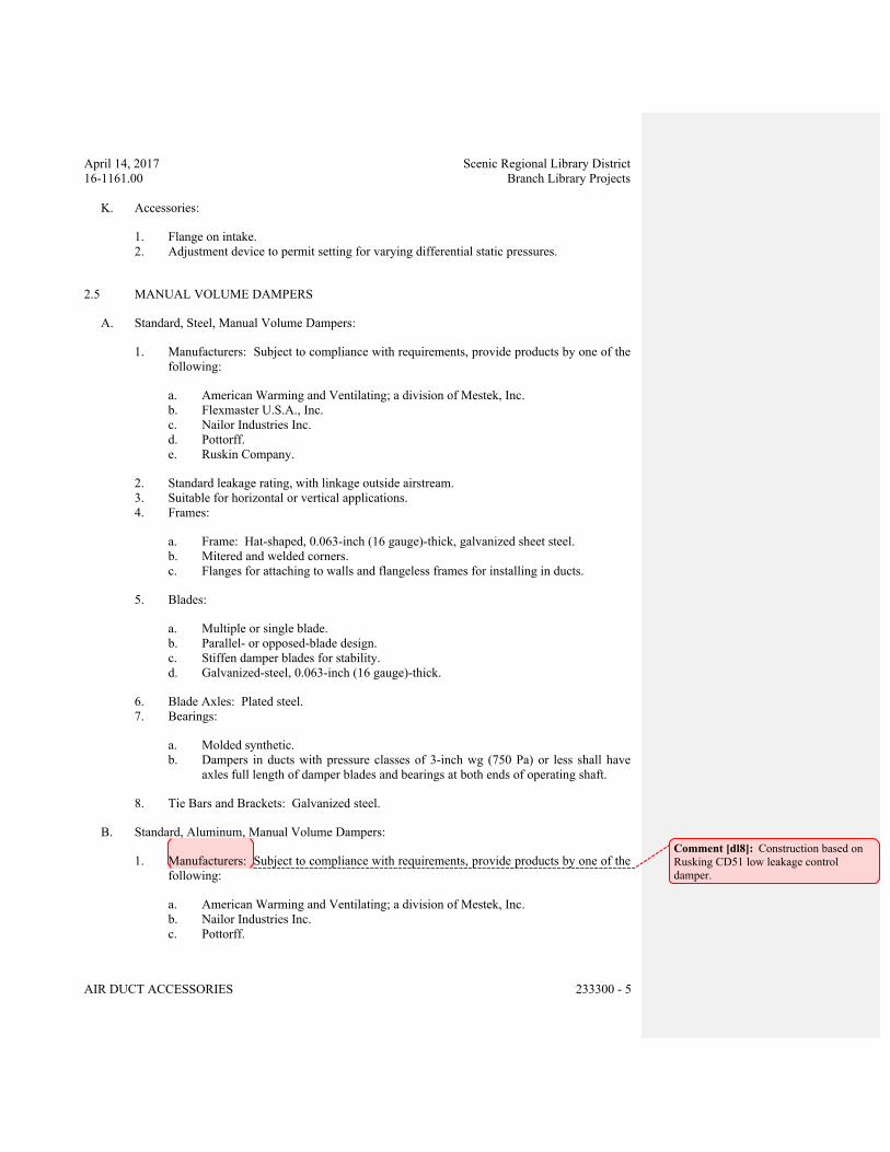
April 14, 2017 Scenic Regional Library District
16-1161.00 Branch Library Projects
AIR DUCT ACCESSORIES 233300 - 5
K. Accessories:
1. Flange on intake.
2. Adjustment device to permit setting for varying differential static pressures.
2.5 MANUAL VOLUME DAMPERS
A. Standard, Steel, Manual Volume Dampers:
1. Manufacturers: Subject to compliance with requirements, provide products by one of the
following:
a. American Warming and Ventilating; a division of Mestek, Inc.
b. Flexmaster U.S.A., Inc.
c. Nailor Industries Inc.
d. Pottorff.
e. Ruskin Company.
2. Standard leakage rating, with linkage outside airstream.
3. Suitable for horizontal or vertical applications.
4. Frames:
a. Frame: Hat-shaped, 0.063-inch (16 gauge)-thick, galvanized sheet steel.
b. Mitered and welded corners.
c. Flanges for attaching to walls and flangeless frames for installing in ducts.
5. Blades:
a. Multiple or single blade.
b. Parallel- or opposed-blade design.
c. Stiffen damper blades for stability.
d. Galvanized-steel, 0.063-inch (16 gauge)-thick.
6. Blade Axles: Plated steel.
7. Bearings:
a. Molded synthetic.
b. Dampers in ducts with pressure classes of 3-inch wg (750 Pa) or less shall have
axles full length of damper blades and bearings at both ends of operating shaft.
8. Tie Bars and Brackets: Galvanized steel.
B. Standard, Aluminum, Manual Volume Dampers:
1. Manufacturers: Subject to compliance with requirements, provide products by one of the
following:
a. American Warming and Ventilating; a division of Mestek, Inc.
b. Nailor Industries Inc.
c. Pottorff.
Comment [dl8]: Construction based on
Rusking CD51 low leakage control
damper.
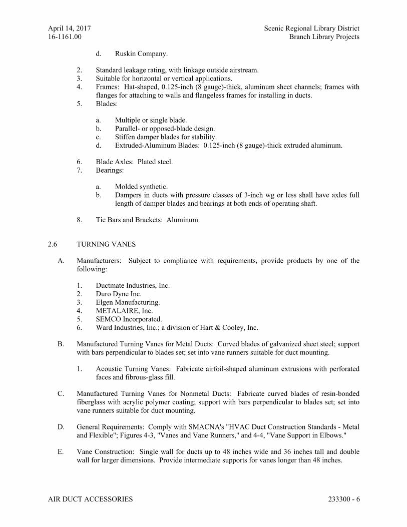
April 14, 2017 Scenic Regional Library District
16-1161.00 Branch Library Projects
AIR DUCT ACCESSORIES 233300 - 6
d. Ruskin Company.
2. Standard leakage rating, with linkage outside airstream.
3. Suitable for horizontal or vertical applications.
4. Frames: Hat-shaped, 0.125-inch (8 gauge)-thick, aluminum sheet channels; frames with
flanges for attaching to walls and flangeless frames for installing in ducts.
5. Blades:
a. Multiple or single blade.
b. Parallel- or opposed-blade design.
c. Stiffen damper blades for stability.
d. Extruded-Aluminum Blades: 0.125-inch (8 gauge)-thick extruded aluminum.
6. Blade Axles: Plated steel.
7. Bearings:
a. Molded synthetic.
b. Dampers in ducts with pressure classes of 3-inch wg or less shall have axles full
length of damper blades and bearings at both ends of operating shaft.
8. Tie Bars and Brackets: Aluminum.
2.6 TURNING VANES
A. Manufacturers: Subject to compliance with requirements, provide products by one of the
following:
1. Ductmate Industries, Inc.
2. Duro Dyne Inc.
3. Elgen Manufacturing.
4. METALAIRE, Inc.
5. SEMCO Incorporated.
6. Ward Industries, Inc.; a division of Hart & Cooley, Inc.
B. Manufactured Turning Vanes for Metal Ducts: Curved blades of galvanized sheet steel; support
with bars perpendicular to blades set; set into vane runners suitable for duct mounting.
1. Acoustic Turning Vanes: Fabricate airfoil-shaped aluminum extrusions with perforated
faces and fibrous-glass fill.
C. Manufactured Turning Vanes for Nonmetal Ducts: Fabricate curved blades of resin-bonded
fiberglass with acrylic polymer coating; support with bars perpendicular to blades set; set into
vane runners suitable for duct mounting.
D. General Requirements: Comply with SMACNA's "HVAC Duct Construction Standards - Metal
and Flexible"; Figures 4-3, "Vanes and Vane Runners," and 4-4, "Vane Support in Elbows."
E. Vane Construction: Single wall for ducts up to 48 inches wide and 36 inches tall and double
wall for larger dimensions. Provide intermediate supports for vanes longer than 48 inches.
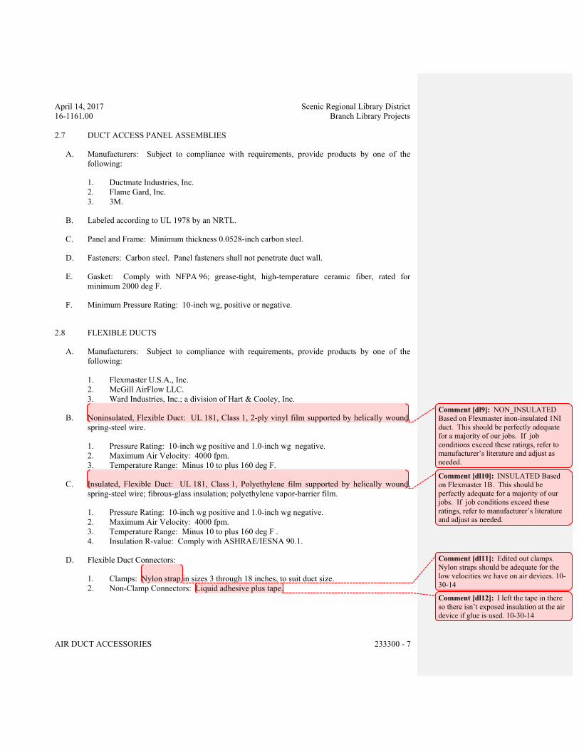
April 14, 2017 Scenic Regional Library District
16-1161.00 Branch Library Projects
AIR DUCT ACCESSORIES 233300 - 7
2.7 DUCT ACCESS PANEL ASSEMBLIES
A. Manufacturers: Subject to compliance with requirements, provide products by one of the
following:
1. Ductmate Industries, Inc.
2. Flame Gard, Inc.
3. 3M.
B. Labeled according to UL 1978 by an NRTL.
C. Panel and Frame: Minimum thickness 0.0528-inch carbon steel.
D. Fasteners: Carbon steel. Panel fasteners shall not penetrate duct wall.
E. Gasket: Comply with NFPA 96; grease-tight, high-temperature ceramic fiber, rated for
minimum 2000 deg F.
F. Minimum Pressure Rating: 10-inch wg, positive or negative.
2.8 FLEXIBLE DUCTS
A. Manufacturers: Subject to compliance with requirements, provide products by one of the
following:
1. Flexmaster U.S.A., Inc.
2. McGill AirFlow LLC.
3. Ward Industries, Inc.; a division of Hart & Cooley, Inc.
B. Noninsulated, Flexible Duct: UL 181, Class 1, 2-ply vinyl film supported by helically wound,
spring-steel wire.
1. Pressure Rating: 10-inch wg positive and 1.0-inch wg negative.
2. Maximum Air Velocity: 4000 fpm.
3. Temperature Range: Minus 10 to plus 160 deg F.
C. Insulated, Flexible Duct: UL 181, Class 1, Polyethylene film supported by helically wound,
spring-steel wire; fibrous-glass insulation; polyethylene vapor-barrier film.
1. Pressure Rating: 10-inch wg positive and 1.0-inch wg negative.
2. Maximum Air Velocity: 4000 fpm.
3. Temperature Range: Minus 10 to plus 160 deg F .
4. Insulation R-value: Comply with ASHRAE/IESNA 90.1.
D. Flexible Duct Connectors:
1. Clamps: Nylon strap in sizes 3 through 18 inches, to suit duct size.
2. Non-Clamp Connectors: Liquid adhesive plus tape.
Comment [dl9]: NON_INSULATED
Based on Flexmaster inon-insulated 1NI
duct. This should be perfectly adequate
for a majority of our jobs. If job
conditions exceed these ratings, refer to
manufacturer’s literature and adjust as
needed.
Comment [dl10]: INSULATED Based
on Flexmaster 1B. This should be
perfectly adequate for a majority of our
jobs. If job conditions exceed these
ratings, refer to manufacturer’s literature
and adjust as needed.
Comment [dl11]: Edited out clamps.
Nylon straps should be adequate for the
low velocities we have on air devices. 10-
30-14
Comment [dl12]: I left the tape in there
so there isn’t exposed insulation at the air
device if glue is used. 10-30-14
April 14, 2017 Scenic Regional Library District
16-1161.00 Branch Library Projects
AIR DUCT ACCESSORIES 233300 - 8
2.9 DUCT ACCESSORY HARDWARE
A. Instrument Test Holes: Cast iron or cast aluminum to suit duct material, including screw cap
and gasket. Size to allow insertion of pitot tube and other testing instruments and of length to
suit duct-insulation thickness.
B. Adhesives: High strength, quick setting, neoprene based, waterproof, and resistant to gasoline
and grease.
PART 3 - EXECUTION
3.1 INSTALLATION
A. Install duct accessories according to applicable details in SMACNA's "HVAC Duct
Construction Standards - Metal and Flexible" for metal ducts and in NAIMA AH116, "Fibrous
Glass Duct Construction Standards," for fibrous-glass ducts.
B. Install duct accessories of materials suited to duct materials; use galvanized-steel accessories in
galvanized-steel and fibrous-glass ducts, stainless-steel accessories in stainless-steel ducts, and
aluminum accessories in aluminum ducts.
C. Install backdraft dampers at inlet of exhaust fans or exhaust ducts as close as possible to exhaust
fan unless otherwise indicated.
D. Install volume dampers at points on supply, return, and exhaust systems where branches extend
from larger ducts. Where dampers are installed in ducts having duct liner, install dampers with
hat channels of same depth as liner, and terminate liner with nosing at hat channel.
1. Install steel volume dampers in steel ducts.
2. Install aluminum volume dampers in aluminum ducts.
E. Set dampers to fully open position before testing, adjusting, and balancing.
F. Install test holes at fan inlets and outlets and elsewhere as indicated.
G. Install duct access doors on sides of ducts to allow for inspecting, adjusting, and maintaining
accessories and equipment at the following locations:
1. On both sides of duct coils.
2. Upstream and downstream from duct filters.
3. At outdoor-air intakes and mixed-air plenums.
4. At drain pans and seals.
5. Downstream from manual volume dampers, control dampers, backdraft dampers, and
equipment.
6. Adjacent to and close enough to fire or smoke dampers, to reset or reinstall fusible links.
Access doors for access to fire or smoke dampers having fusible links shall be pressure
relief access doors and shall be outward operation for access doors installed upstream
from dampers and inward operation for access doors installed downstream from dampers.
7. At each change in direction and at maximum 50-foot spacing.
April 14, 2017 Scenic Regional Library District
16-1161.00 Branch Library Projects
AIR DUCT ACCESSORIES 233300 - 9
8. Upstream and downstream from turning vanes.
9. Upstream or downstream from duct silencers.
10. Control devices requiring inspection.
11. Elsewhere as indicated.
H. Install access doors with swing against duct static pressure.
I. Access Door Sizes:
1. One-Hand or Inspection Access: 8 by 5 inches.
2. Two-Hand Access: 12 by 6 inches.
3. Head and Hand Access: 18 by 10 inches.
4. Head and Shoulders Access: 21 by 14 inches.
5. Body Access: 25 by 14 inches.
6. Body plus Ladder Access: 25 by 17 inches.
J. Label access doors according to Section 230553 "Identification for HVAC Piping and
Equipment" to indicate the purpose of access door.
K. Install flexible connectors to connect ducts to equipment.
L. For fans developing static pressures of 5-inch wg and more, cover flexible connectors with
loaded vinyl sheet held in place with metal straps.
M. Connect diffusers or light troffer boots to ducts with maximum 60-inch lengths of flexible duct
clamped or strapped in place.
N. Connect flexible ducts to metal ducts with liquid adhesive plus tape or draw bands.
O. Install duct test holes where required for testing and balancing purposes.
P. Install thrust limits at centerline of thrust, symmetrical on both sides of equipment. Attach
thrust limits at centerline of thrust and adjust to a maximum of 1/4-inch movement during start
and stop of fans.
3.2 FIELD QUALITY CONTROL
A. Tests and Inspections:
1. Operate dampers to verify full range of movement.
2. Inspect locations of access doors and verify that purpose of access door can be
performed.
3. Operate fire, smoke, and combination fire and smoke dampers to verify full range of
movement and verify that proper heat-response device is installed.
4. Inspect turning vanes for proper and secure installation.
5. Operate remote damper operators to verify full range of movement of operator and
damper.
END OF SECTION 233300
April 14, 2017 Scenic Regional Library District
16-1161.00 Branch Library Projects
DIFFUSERS, REGISTERS, AND GRILLES 233713 - 1
SECTION 233713 - DIFFUSERS, REGISTERS, AND GRILLES
ALL LIBRARIES
PART 1 - GENERAL
1.1 RELATED DOCUMENTS
A. Drawings and general provisions of the Contract, including General and Supplementary
Conditions and Division 01 Specification Sections, apply to this Section.
1.2 SUMMARY
A. Related Sections:
1. Section 089116 "Operable Wall Louvers" and Section 089119 "Fixed Louvers" for fixed
and adjustable louvers and wall vents, whether or not they are connected to ducts.
2. Section 233300 "Air Duct Accessories" for fire and smoke dampers and volume-control
dampers not integral to diffusers, registers, and grilles.
1.3 ACTION SUBMITTALS
A. Product Data: For each type of product indicated, include the following:
1. Data Sheet: Indicate materials of construction, finish, and mounting details; and
performance data including throw and drop, static-pressure drop, and noise ratings.
2. Diffuser, Register, and Grille Schedule: Indicate drawing designation, room location,
quantity, model number, size, and accessories furnished.
1.4 INFORMATIONAL SUBMITTALS
A. Coordination Drawings: Reflected ceiling plans, drawn to scale, on which the following items
are shown and coordinated with each other, using input from Installers of the items involved:
1. Ceiling suspension assembly members.
2. Method of attaching hangers to building structure.
3. Size and location of initial access modules for acoustical tile.
4. Ceiling-mounted items including lighting fixtures, diffusers, grilles, speakers, sprinklers,
access panels, and special moldings.
5. Duct access panels.
B. Source quality-control reports.
April 14, 2017 Scenic Regional Library District
16-1161.00 Branch Library Projects
DIFFUSERS, REGISTERS, AND GRILLES 233713 - 2
PART 2 - PRODUCTS
2.1 CEILING DIFFUSERS
A. All Ceiling Diffusers:
1. Manufacturers: Subject to compliance with requirements, provide products by one of the
following:
a. Carnes.
b. Krueger
c. METALAIRE, Inc.
d. Nailor Industries Inc.
e. Price Industries.
f. Titus.
g. Tuttle & Bailey.
2. See schedule on drawings for performance and construction requirements.
2.2 REGISTERS AND GRILLES
A. All registers and grilles:
1. Manufacturers: Subject to compliance with requirements, [provide products by one of
the following:
a. Carnes.
b. Krueger.
c. METALAIRE, Inc.
d. Nailor Industries Inc.
e. Price Industries.
f. Titus.
g. Tuttle & Bailey.
2. See schedule on drawings for performance and construction requirements.
2.3 SOURCE QUALITY CONTROL
A. Verification of Performance: Rate diffusers, registers, and grilles according to ASHRAE 70,
"Method of Testing for Rating the Performance of Air Outlets and Inlets."
April 14, 2017 Scenic Regional Library District
16-1161.00 Branch Library Projects
DIFFUSERS, REGISTERS, AND GRILLES 233713 - 3
PART 3 - EXECUTION
3.1 EXAMINATION
A. Examine areas where diffusers, registers, and grilles are to be installed for compliance with
requirements for installation tolerances and other conditions affecting performance of
equipment.
B. Proceed with installation only after unsatisfactory conditions have been corrected.
3.2 INSTALLATION
A. Install diffusers, registers, and grilles level and plumb.
B. Ceiling-Mounted Outlets and Inlets: Drawings indicate general arrangement of ducts, fittings,
and accessories. Air outlet and inlet locations have been indicated to achieve design
requirements for air volume, noise criteria, airflow pattern, throw, and pressure drop. Make
final locations where indicated, as much as practical. For units installed in lay-in ceiling panels,
locate units in the center of panel. Where architectural features or other items conflict with
installation, notify Architect for a determination of final location.
C. Install diffusers, registers, and grilles with airtight connections to ducts and to allow service and
maintenance of dampers, air extractors, and fire dampers.
3.3 ADJUSTING
A. After installation, adjust diffusers, registers, and grilles to air patterns indicated, or as directed,
before starting air balancing.
END OF SECTION 233713
April 14, 2017 Scenic Regional Library District
16-1161.00 Branch Library Projects
PACKAGED, OUTDOOR, CENTRAL-STATION AIR-HANDLING UNITS 237413 - 1
SECTION 237413 - PACKAGED, OUTDOOR, CENTRAL-STATION AIR-HANDLING UNITS
ALL LIBRARIES
PART 1 - GENERAL
1.1 RELATED DOCUMENTS
A. Drawings and general provisions of the Contract, including General and Supplementary
Conditions and Division 01 Specification Sections, apply to this Section.
1.2 SUMMARY
A. This Section includes packaged, outdoor, central-station air-handling units (rooftop units) with
the following components and accessories:
1. Direct-expansion cooling.
2. Hot-gas reheat.
3. Gas furnace.
4. Economizer outdoor- and return-air damper section.
5. Integral, space temperature controls.
6. Roof curbs.
B. Related Sections include the following:
1. Section 237333.16 "Indoor, Indirect, Gas-Fired Heating and Ventilating Units" for
outdoor units providing 100 percent tempered outdoor air with heat exchangers.
2. Section 237339 "Indoor, Direct-Fired Heating and Ventilating Units" for outdoor units
providing 100 percent tempered outdoor air without heat exchangers.
3. Section 237433 "Dedicated Outdoor-Air Units" for outdoor equipment air conditioning
100 percent outdoor air to replace air exhausted from a building.
1.3 DEFINITIONS
A. DDC: Direct-digital controls.
B. ECM: Electrically commutated motor.
C. Outdoor-Air Refrigerant Coil: Refrigerant coil in the outdoor-air stream to reject heat during
cooling operations and to absorb heat during heating operations. "Outdoor air" is defined as the
air outside the building or taken from outdoors and not previously circulated through the
system.
D. Outdoor-Air Refrigerant-Coil Fan: The outdoor-air refrigerant-coil fan in RTUs. "Outdoor air"
is defined as the air outside the building or taken from outdoors and not previously circulated
through the system.
April 14, 2017 Scenic Regional Library District
16-1161.00 Branch Library Projects
PACKAGED, OUTDOOR, CENTRAL-STATION AIR-HANDLING UNITS 237413 - 2
E. RTU: Rooftop unit. As used in this Section, this abbreviation means packaged, outdoor,
central-station air-handling units. This abbreviation is used regardless of whether the unit is
mounted on the roof or on a concrete base on ground.
F. Supply-Air Fan: The fan providing supply air to conditioned space. "Supply air" is defined as
the air entering a space from air-conditioning, heating, or ventilating apparatus.
G. Supply-Air Refrigerant Coil: Refrigerant coil in the supply-air stream to absorb heat (provide
cooling) during cooling operations and to reject heat (provide heating) during heating
operations. "Supply air" is defined as the air entering a space from air-conditioning, heating, or
ventilating apparatus.
H. VVT: Variable-air volume and temperature.
1.4 PERFORMANCE REQUIREMENTS
A. Delegated Design: Design RTU supports to comply with [wind] [and] [seismic] performance
requirements, including comprehensive engineering analysis by a qualified professional
engineer, using performance requirements and design criteria indicated.
B. Wind-Restraint Performance:
1. Basic Wind Speed: 120.
2. Building Classification Category: III.
3. Minimum 10 lb/sq. ft multiplied by the maximum area of the mechanical component
projected on a vertical plane that is normal to the wind direction, and 45 degrees either
side of normal.
C. Seismic Performance: RTUs shall withstand the effects of earthquake motions determined
according to SEI/ASCE 7.
1. The term "withstand" means "the unit will remain in place without separation of any parts
from the device when subjected to the seismic forces specified."
1.5 ACTION SUBMITTALS
A. Product Data: Include manufacturer's technical data for each RTU, including rated capacities,
dimensions, required clearances, characteristics, furnished specialties, and accessories.
B. Shop Drawings: Detail equipment assemblies and indicate dimensions, weights, loads, required
clearances, method of field assembly, components, and location and size of each field
connection.
1. Wiring Diagrams: Power, signal, and control wiring.
C. Delegated-Design Submittal: For RTU supports indicated to comply with performance
requirements and design criteria, including analysis data signed and sealed by the qualified
professional engineer responsible for their preparation.
April 14, 2017 Scenic Regional Library District
16-1161.00 Branch Library Projects
PACKAGED, OUTDOOR, CENTRAL-STATION AIR-HANDLING UNITS 237413 - 3
1. Design Calculations: Calculate requirements for selecting vibration isolators and seismic
restraints and for designing vibration isolation bases.
2. Detail mounting, securing, and flashing of roof curb to roof structure. Indicate
coordinating requirements with roof membrane system.
3. Wind and Seismic Restraint Details: Detail fabrication and attachment of wind and
seismic restraints and snubbers. Show anchorage details and indicate quantity, diameter,
and depth of penetration of anchors.
1.6 INFORMATIONAL SUBMITTALS
A. Coordination Drawings: Plans and other details, drawn to scale, on which the following items
are shown and coordinated with each other, using input from installers of the items involved:
1. Structural members to which RTUs will be attached.
2. Roof openings
3. Roof curbs and flashing.
B. Manufacturer Wind Loading Qualification Certification: Submit certification that specified
equipment will withstand wind forces identified in "Performance Requirements" Article and in
Section 230548 "Vibration and Seismic Controls for HVAC."
1. Basis for Certification: Indicate whether withstand certification is based on actual test of
assembled components or on calculations.
2. Dimensioned Outline Drawings of Equipment Unit: Identify center of wind force and
locate and describe mounting and anchorage provisions.
3. Detailed description of equipment anchorage devices on which the certification is based
and their installation requirements.
C. Manufacturer Seismic Qualification Certification: Submit certification that RTUs, accessories,
and components will withstand seismic forces defined in "Performance Requirements" Article
and in Section 230548 "Vibration and Seismic Controls for HVAC."
1. Basis for Certification: Indicate whether withstand certification is based on actual test of
assembled components or on calculation.
2. Dimensioned Outline Drawings of Equipment Unit: Identify center of gravity and locate
and describe mounting and anchorage provisions.
3. Detailed description of equipment anchorage devices on which the certification is based
and their installation requirements.
D. Field quality-control test reports.
E. Warranty: Special warranty specified in this Section.
1.7 CLOSEOUT SUBMITTALS
A. Operation and Maintenance Data: For RTUs to include in emergency, operation, and
maintenance manuals.
April 14, 2017 Scenic Regional Library District
16-1161.00 Branch Library Projects
PACKAGED, OUTDOOR, CENTRAL-STATION AIR-HANDLING UNITS 237413 - 4
1.8 MAINTENANCE MATERIAL SUBMITTALS
A. Furnish extra materials described below that match products installed and that are packaged
with protective covering for storage and identified with labels describing contents.
1. Fan Belts: One set for each belt-driven fan.
2. Filters: One set of filters for each unit.
1.9 QUALITY ASSURANCE
A. ARI Compliance:
1. Comply with ARI 203/110 and ARI 303/110 for testing and rating energy efficiencies for
RTUs.
2. Comply with ARI 270 for testing and rating sound performance for RTUs.
B. ASHRAE Compliance:
1. Comply with ASHRAE 15 for refrigeration system safety.
2. Comply with ASHRAE 33 for methods of testing cooling and heating coils.
3. Comply with applicable requirements in ASHRAE 62.1, Section 5 - "Systems and
Equipment" and Section 7 - "Construction and Startup."
C. ASHRAE/IESNA 90.1 Compliance: Applicable requirements in ASHRAE/IESNA 90.1,
Section 6 - "Heating, Ventilating, and Air-Conditioning."
D. NFPA Compliance: Comply with NFPA 90A and NFPA 90B.
E. UL Compliance: Comply with UL 1995.
F. Electrical Components, Devices, and Accessories: Listed and labeled as defined in NFPA 70,
Article 100, by a testing agency acceptable to authorities having jurisdiction, and marked for
intended use.
1.10 WARRANTY
A. Special Warranty: Manufacturer's standard form in which manufacturer agrees to replace
components of RTUs that fail in materials or workmanship within specified warranty period.
1. Warranty Period for Compressors: Manufacturer's standard, but not less than five years
from date of Substantial Completion.
2. Warranty Period for Gas Furnace Heat Exchangers: Manufacturer's standard, but not less
than 10 years from date of Substantial Completion.
3. Warranty Period for Solid-State Ignition Modules: Manufacturer's standard, but not less
than three years from date of Substantial Completion.
4. Warranty Period for Control Boards: Manufacturer's standard, but not less than three
years from date of Substantial Completion.
April 14, 2017 Scenic Regional Library District
16-1161.00 Branch Library Projects
PACKAGED, OUTDOOR, CENTRAL-STATION AIR-HANDLING UNITS 237413 - 5
PART 2 - PRODUCTS
2.1 MANUFACTURERS
A. Available Manufacturers: Subject to compliance with requirements, manufacturers offering
products that may be incorporated into the Work include, but are not limited to, the following:
B. Manufacturers: Subject to compliance with requirements, provide products by one of the
following:
C. Basis-of-Design Product: Subject to compliance with requirements, provide the product
indicated on Drawingsor a comparable product by one of the following:
1. AAON, Inc.
2. Addison Products Company.
3. Carrier Corporation.
4. Engineered Air.
5. Lennox Industries Inc.
6. McQuay International.
7. Trane; American Standard Companies, Inc.
8. YORK International Corporation.
9. Tempmaster
2.2 CASING
A. General Fabrication Requirements for Casings: Formed and reinforced double-wall insulated
panels, fabricated to allow removal for access to internal parts and components, with joints
between sections sealed.
B. Exterior Casing Material: Galvanized steel with factory-painted finish, with pitched roof panels
and knockouts with grommet seals for electrical and piping connections and lifting lugs.
1. Exterior Casing Thickness: 0.0626 inch thick.
C. Inner Casing Fabrication Requirements:
1. Inside Casing: Galvanized steel, 0.034 inch thick.
D. Casing Insulation and Adhesive: Comply with NFPA 90A or NFPA 90B.
1. Materials: ASTM C 1071, Type I.
2. Thickness: 1 inch.
3. Liner materials shall have air-stream surface coated with an erosion- and temperature-
resistant coating or faced with a plain or coated fibrous mat or fabric.
4. Liner Adhesive: Comply with ASTM C 916, Type I.
E. Condensate Drain Pans: Formed sections of stainless-steel sheet, a minimum of 2 inches
deep[, and complying with ASHRAE 62.1.
April 14, 2017 Scenic Regional Library District
16-1161.00 Branch Library Projects
PACKAGED, OUTDOOR, CENTRAL-STATION AIR-HANDLING UNITS 237413 - 6
1. Double-Wall Construction: Fill space between walls with foam insulation and seal
moisture tight.
2. Drain Connections: Threaded nipple both sides of drain pan.
3. Pan-Top Surface Coating: Corrosion-resistant compound.
F. Airstream Surfaces: Surfaces in contact with the airstream shall comply with requirements in
ASHRAE 62.1.
2.3 FANS
A. Direct-Driven Supply-Air Fans: Double width, backward inclined, centrifugal; with
permanently lubricated, multispeed motor resiliently mounted in the fan inlet. Aluminum or
painted-steel wheels, and galvanized- or painted-steel fan scrolls.
B. Belt-Driven Supply-Air Fans: Double width, forward curved, centrifugal; with permanently
lubricated, single-speed motor installed on an adjustable fan base resiliently mounted in the
casing. Aluminum or painted-steel wheels, and galvanized- or painted-steel fan scrolls.
C. Condenser-Coil Fan: Propeller, mounted on shaft of permanently lubricated motor.
D. Seismic Fabrication Requirements: Fabricate fan section, internal mounting frame and
attachment to fans, fan housings, motors, casings, accessories, and other fan section components
with reinforcement strong enough to withstand seismic forces defined in Section 230548
"Vibration and Seismic Controls for HVAC" when fan-mounted frame and RTU-mounted
frame are anchored to building structure.
E. Fan Motor: Comply with requirements in Section 230513 "Common Motor Requirements for
HVAC Equipment."
2.4 COILS
A. Supply-Air Refrigerant Coil:
1. Aluminum plate fin and seamless internally grooved copper tube in steel casing with
equalizing-type vertical distributor.
2. Polymer strip shall prevent all copper coil from contacting steel coil frame or condensate
pan.
3. Coil Split: Interlaced.
4. [Baked phenolic coating.
5. Condensate Drain Pan: Stainless steel formed with pitch and drain
connections complying with ASHRAE 62.1.
2.5 REFRIGERANT CIRCUIT COMPONENTS
A. Number of Refrigerant Circuits: One.
B. Compressor: Hermetic, scroll, mounted on vibration isolators; with internal overcurrent and
high-temperature protection, internal pressure relief[, and crankcase heater.
April 14, 2017 Scenic Regional Library District
16-1161.00 Branch Library Projects
PACKAGED, OUTDOOR, CENTRAL-STATION AIR-HANDLING UNITS 237413 - 7
C. Refrigeration Specialties:
1. Refrigerant: R-410A.
2. Expansion valve with replaceable thermostatic element.
3. Refrigerant filter/dryer.
4. Manual-reset high-pressure safety switch.
5. Automatic-reset low-pressure safety switch.
6. Minimum off-time relay.
7. Automatic-reset compressor motor thermal overload.
8. Brass service valves installed in compressor suction and liquid lines.
9. Low-ambient kit high-pressure sensor.
10. Hot-gas reheat solenoid valve with a replaceable magnetic coil.
11. Hot-gas bypass solenoid valve with a replaceable magnetic coil.
12. Four-way reversing valve with a replaceable magnetic coil, thermostatic expansion
valves with bypass check valves, and a suction line accumulator.
2.6 AIR FILTRATION
A. Minimum arrestance according to ASHRAE 52.1, and a minimum efficiency reporting value
(MERV) according to ASHRAE 52.2.
1. Pleated: Minimum 90 percent arrestance, and MERV 7.
2.7 GAS FURNACE
A. Description: Factory assembled, piped, and wired; complying with ANSI Z21.47 and
NFPA 54.
1. CSA Approval: Designed and certified by and bearing label of CSA.
B. Burners: Stainless steel.
1. Fuel: Natural gas.
2. Ignition: Electronically controlled electric spark or hot-surface igniter with flame sensor.
3. High-Altitude Model: For Project elevations more than 2000 feet above sea level.
C. Heat-Exchanger and Drain Pan: Stainless steel.
D. Venting: Gravity vented with vertical extension.
E. Power Vent: Integral, motorized centrifugal fan interlocked with gas valve with vertical
extension.
F. Safety Controls:
1. Gas Control Valve: Two stage.
2. Gas Train: Single-body, regulated, redundant, 24-V ac gas valve assembly containing
pilot solenoid valve, pilot filter, pressure regulator, pilot shutoff, and manual shutoff.
April 14, 2017 Scenic Regional Library District
16-1161.00 Branch Library Projects
PACKAGED, OUTDOOR, CENTRAL-STATION AIR-HANDLING UNITS 237413 - 8
2.8 DAMPERS
A. Outdoor-Air Damper: Linked damper blades, for 0 to 25 percent outdoor air, with manual
damper filter.
B. Outdoor- and Return-Air Mixing Dampers: Parallel- or opposed-blade galvanized-steel
dampers mechanically fastened to cadmium plated for galvanized-steel operating rod in
reinforced cabinet. Connect operating rods with common linkage and interconnect linkages so
dampers operate simultaneously.
1. Damper Motor: Modulating with adjustable minimum position.
2. Relief-Air Damper: Gravity actuated or motorized, as required by
ASHRAE/IESNA 90.1, with bird screen and hood.
2.9 ELECTRICAL POWER CONNECTION
A. Provide for single connection of power to unit with unit-mounted disconnect switch accessible
from outside unit and control-circuit transformer with built-in overcurrent protection.
2.10 CONTROLS
A. Control equipment and sequence of operation are specified in Section 230900 "Instrumentation
and Control for HVAC."
B. Basic Unit Controls:
1. Control-voltage transformer.
2. Wall-mounted thermostat or sensor with the following features:
a. Heat-cool-off switch.
b. Fan on-auto switch.
c. Fan-speed switch.
d. Automatic changeover.
e. Adjustable deadband.
f. Exposed set point.
g. Exposed indication.
h. Degree F indication.
i. Unoccupied-period-override push button.
j. Data entry and access port to input temperature set points, occupied and
unoccupied periods, and output room temperature, supply-air temperature,
operating mode, and status.
2.11 ACCESSORIES
A. Electric heater with integral thermostat maintains minimum 50 deg F temperature in gas burner
compartment.
April 14, 2017 Scenic Regional Library District
16-1161.00 Branch Library Projects
PACKAGED, OUTDOOR, CENTRAL-STATION AIR-HANDLING UNITS 237413 - 9
B. Duplex, 115-V, ground-fault-interrupter outlet with 15-A overcurrent protection. Include
transformer if required. Outlet shall be energized even if the unit main disconnect is open.
C. Low-ambient kit using variable-speed condenser fans for operation down to 35 deg F.
D. Filter differential pressure switch with sensor tubing on either side of filter. Set for final filter
pressure loss.
E. Coil guards of painted, galvanized-steel wire.
F. Hail guards of galvanized steel, painted to match casing.
G. Concentric diffuser with white louvers and polished aluminum return grilles, insulated diffuser
box with mounting flanges, and interior transition.
2.12 ROOF CURBS
A. Roof curbs with vibration isolators and wind or seismic restraints are specified in
Section 230548 "Vibration and Seismic Controls for HVAC."
B. Materials: Galvanized steel with corrosion-protection coating, watertight gaskets, and factory-
installed wood nailer; complying with NRCA standards.
1. Curb Insulation and Adhesive: Comply with NFPA 90A or NFPA 90B.
a. Materials: ASTM C 1071, Type I or II.
b. Thickness: 1 inch.
2. Application: Factory applied with adhesive and mechanical fasteners to the internal
surface of curb.
a. Liner Adhesive: Comply with ASTM C 916, Type I.
b. Mechanical Fasteners: Galvanized steel, suitable for adhesive attachment,
mechanical attachment, or welding attachment to duct without damaging liner
when applied as recommended by manufacturer and without causing leakage in
cabinet.
c. Liner materials applied in this location shall have air-stream surface coated with a
temperature-resistant coating or faced with a plain or coated fibrous mat or fabric
depending on service air velocity.
d. Liner Adhesive: Comply with ASTM C 916, Type I.
C. Curb Height: 24 inches.
D. Wind and Seismic Restraints: Metal brackets compatible with the curb and casing, painted to
match RTU, used to anchor unit to the curb, and designed for loads at Project site. Comply with
requirements in Section 230548 "Vibration and Seismic Controls for HVAC" for wind-load
requirements.
April 14, 2017 Scenic Regional Library District
16-1161.00 Branch Library Projects
PACKAGED, OUTDOOR, CENTRAL-STATION AIR-HANDLING UNITS 237413 - 10
PART 3 - EXECUTION
3.1 EXAMINATION
A. Examine substrates, areas, and conditions, with Installer present, for compliance with
requirements for installation tolerances and other conditions affecting performance of RTUs.
B. Examine roughing-in for RTUs to verify actual locations of piping and duct connections before
equipment installation.
C. Examine roofs for suitable conditions where RTUs will be installed.
D. Proceed with installation only after unsatisfactory conditions have been corrected.
3.2 INSTALLATION
A. Equipment Mounting:
1. Install RTUs on cast-in-place concrete equipment bases. Comply with requirements for
equipment bases and foundations specified in Section 033000 "Cast-in-Place Concrete."
2. Comply with requirements for vibration isolation and seismic control devices specified in
Section 230548 "Vibration and Seismic Controls for HVAC."
3. Comply with requirements for vibration isolation devices specified in Section 230548.13
"Vibration Controls for HVAC."
B. Roof Curb: Install on roof structure or concrete base, level and secure, according to NRCA's
"Low-Slope Membrane Roofing Construction Details Manual," Illustration "Raised Curb Detail
for Rooftop Air Handling Units and Ducts." Install RTUs on curbs and coordinate roof
penetrations and flashing with roof construction specified in Section 077200 "Roof
Accessories." Secure RTUs to upper curb rail, and secure curb base to roof framing or concrete
base with anchor bolts.
C. Unit Support: Install unit level on structural curbs. Coordinate wall penetrations and flashing
with wall construction. Secure RTUs to structural support with anchor bolts.
3.3 CONNECTIONS
A. Install condensate drain, minimum connection size, with trap and indirect connection to nearest
roof drain or area drain.
B. Install piping adjacent to RTUs to allow service and maintenance.
1. Gas Piping: Comply with applicable requirements in Section 221600. Connect gas
piping to burner, full size of gas train inlet, and connect with union and shutoff valve with
sufficient clearance for burner removal and service.
C. Duct installation requirements are specified in other HVAC Sections. Drawings indicate the
general arrangement of ducts. The following are specific connection requirements:
April 14, 2017 Scenic Regional Library District
16-1161.00 Branch Library Projects
PACKAGED, OUTDOOR, CENTRAL-STATION AIR-HANDLING UNITS 237413 - 11
1. Install ducts to termination at top of roof curb.
2. Remove roof decking only as required for passage of ducts. Do not cut out decking
under entire roof curb.
3. Connect supply ducts to RTUs with flexible duct connectors specified in Section 233300
"Air Duct Accessories."
4. Install return-air duct continuously through roof structure.
5. Install normal-weight, 3000-psi, compressive strength (28-day) concrete mix inside roof
curb, 4 inches thick. Concrete, formwork, and reinforcement are specified with concrete.
3.4 FIELD QUALITY CONTROL
A. Manufacturer's Field Service: Engage a factory-authorized service representative to inspect,
test, and adjust components, assemblies, and equipment installations, including connections.
Report results in writing.
B. Perform tests and inspections and prepare test reports.
1. Manufacturer's Field Service: Engage a factory-authorized service representative to
inspect components, assemblies, and equipment installations, including connections, and
to assist in testing. Report results in writing.
C. Tests and Inspections:
1. After installing RTUs and after electrical circuitry has been energized, test units for
compliance with requirements.
2. Inspect for and remove shipping bolts, blocks, and tie-down straps.
3. Operational Test: After electrical circuitry has been energized, start units to confirm
proper motor rotation and unit operation.
4. Test and adjust controls and safeties. Replace damaged and malfunctioning controls and
equipment.
D. Remove and replace malfunctioning units and retest as specified above.
3.5 STARTUP SERVICE
A. Engage a factory-authorized service representative to perform startup service.
B. Complete installation and startup checks according to manufacturer's written instructions and do
the following:
1. Inspect for visible damage to unit casing.
2. Inspect for visible damage to furnace combustion chamber.
3. Inspect for visible damage to compressor, coils, and fans.
4. Inspect internal insulation.
5. Verify that labels are clearly visible.
6. Verify that clearances have been provided for servicing.
7. Verify that controls are connected and operable.
8. Verify that filters are installed.
9. Clean condenser coil and inspect for construction debris.
April 14, 2017 Scenic Regional Library District
16-1161.00 Branch Library Projects
PACKAGED, OUTDOOR, CENTRAL-STATION AIR-HANDLING UNITS 237413 - 12
10. Clean furnace flue and inspect for construction debris.
11. Connect and purge gas line.
12. Remove packing from vibration isolators.
13. Inspect operation of barometric relief dampers.
14. Verify lubrication on fan and motor bearings.
15. Inspect fan-wheel rotation for movement in correct direction without vibration and
binding.
16. Adjust fan belts to proper alignment and tension.
17. Start unit according to manufacturer's written instructions.
a. Start refrigeration system.
b. Do not operate below recommended low-ambient temperature.
c. Complete startup sheets and attach copy with Contractor's startup report.
18. Inspect and record performance of interlocks and protective devices; verify sequences.
19. Operate unit for an initial period as recommended or required by manufacturer.
20. Perform the following operations for both minimum and maximum firing. Adjust burner
for peak efficiency.
a. Measure gas pressure on manifold.
b. Inspect operation of power vents.
c. Measure combustion-air temperature at inlet to combustion chamber.
d. Measure flue-gas temperature at furnace discharge.
e. Perform flue-gas analysis. Measure and record flue-gas carbon dioxide and
oxygen concentration.
f. Measure supply-air temperature and volume when burner is at maximum firing
rate and when burner is off. Calculate useful heat to supply air.
21. Calibrate thermostats.
22. Adjust and inspect high-temperature limits.
23. Inspect outdoor-air dampers for proper stroke and interlock with return-air dampers.
24. Start refrigeration system and measure and record the following when ambient is a
minimum of 15 deg F above return-air temperature:
a. Coil leaving-air, dry- and wet-bulb temperatures.
b. Coil entering-air, dry- and wet-bulb temperatures.
c. Outdoor-air, dry-bulb temperature.
d. Outdoor-air-coil, discharge-air, dry-bulb temperature.
25. Inspect controls for correct sequencing of heating, mixing dampers, refrigeration, and
normal and emergency shutdown.
26. Measure and record the following minimum and maximum airflows. Plot fan volumes on
fan curve.
a. Supply-air volume.
b. Return-air volume.
c. Relief-air volume.
d. Outdoor-air intake volume.
27. Simulate maximum cooling demand and inspect the following:
April 14, 2017 Scenic Regional Library District
16-1161.00 Branch Library Projects
PACKAGED, OUTDOOR, CENTRAL-STATION AIR-HANDLING UNITS 237413 - 13
a. Compressor refrigerant suction and hot-gas pressures.
b. Short circuiting of air through condenser coil or from condenser fans to outdoor-air
intake.
28. Verify operation of remote panel including pilot-light operation and failure modes.
Inspect the following:
a. High-temperature limit on gas-fired heat exchanger.
b. Low-temperature safety operation.
c. Filter high-pressure differential alarm.
d. Economizer to minimum outdoor-air changeover.
e. Relief-air fan operation.
f. Smoke and firestat alarms.
29. After startup and performance testing and prior to Substantial Completion, replace
existing filters with new filters.
3.6 CLEANING AND ADJUSTING
A. Occupancy Adjustments: When requested within 12 months of date of Substantial Completion,
provide on-site assistance in adjusting system to suit actual occupied conditions. Provide up to
two visits to site during other-than-normal occupancy hours for this purpose.
B. After completing system installation and testing, adjusting, and balancing RTU and air-
distribution systems, clean filter housings and install new filters.
3.7 DEMONSTRATION
A. Engage a factory-authorized service representative to train Owner's maintenance personnel to
adjust, operate, and maintain RTUs. Refer to Section 017900 "Demonstration and Training."
END OF SECTION 237413
April 14, 2017 Scenic Regional Library District
16-1161.00 Branch Library Projects
SMALL SPLIT-SYSTME AIR-CONDITIONERS 23 81 27 - 1
SECTION 238127 – SMALL SPLIT-SYSTEM AIR-CONDITIONERS
ALL LIBRARIES
PART 1 - GENERAL
1.1 RELATED DOCUMENTS
A. Drawings and general provisions of the Contract, including General and Supplementary
Conditions and Division 01 Specification Sections, apply to this Section.
1.2 SUMMARY
A. Section includes
1. Air cooled condensing units.
2. Indoor air handler (fan & coil) units for duct connection.
3. Indoor ductless fan & coil units.
4. Controls.
1.3 ACTION SUBMITTALS
A. Product Data: For each type of product indicated. Include rated capacities, operating
characteristics, and furnished specialties and accessories. Include performance data in terms of
capacities, outlet velocities, static pressures, sound power characteristics, motor requirements,
and electrical characteristics.
B. Shop Drawings: Include plans, elevations, sections, details, and attachments to other work.
1. Detail equipment assemblies and indicate dimensions, weights, loads, required
clearances, method of field assembly, components, and location and size of each field
connection.
2. Wiring Diagrams: For power, signal, and control wiring.
3. Design Data: Indicate refrigerant pipe sizing.
C. Samples for Initial Selection: For units with factory-applied color finishes.
1.4 INFORMATIONAL SUBMITTALS
A. Field quality-control reports.
B. Warranty: Sample of special warranty.
April 14, 2017 Scenic Regional Library District
16-1161.00 Branch Library Projects
SMALL SPLIT-SYSTME AIR-CONDITIONERS 23 81 27 - 2
1.5 CLOSEOUT SUBMITTALS
A. Operation and Maintenance Data: For split-system air-conditioning units to include in
emergency, operation, and maintenance manuals.
1.6 MAINTENANCE MATERIAL SUBMITTALS
A. Furnish extra materials that match products installed and that are packaged with protective
covering for storage and identified with labels describing contents.
1. Filters: One set for each air-handling unit.
2. Gaskets: One set for each access door.
3. Fan Belts: One set(s) for each air-handling unit fan.
1.7 REFERENCE STANDARDS
A. AHRI 210/240 - Standard for Performance Rating of Unitary Air Conditioning and Air-Source
Heat Pump Equipment; Air-Conditioning, Heating, and Refrigeration Institute; 2008.
B. AHRI 270 - Sound Rating of Outdoor Unitary Equipment; Air-Conditioning, Heating, and
Refrigeration Institute; 2008.
C. AHRI 520 - Performance Rating of Positive Displacement Condensing Units; Air-Conditioning,
Heating, and Refrigeration Institute; 2004.
D. ASHRAE Std 15 - Safety Standard for Refrigeration Systems; American Society of Heating,
Refrigerating and Air-Conditioning Engineers, Inc.; 2013 (ANSI/ASHRAE Std 15).
E. ASHRAE Std 23.1 - Methods of Testing for Rating Positive Displacement Refrigerant
Compressors and Condensing Units that Operate at Subcritical Temperatures of the Refrigerant;
American Society of Heating, Refrigerating and Air-Conditioning Engineers, Inc.; 2010.
F. NFPA 90A - Standard for the Installation of Air-Conditioning and Ventilating Systems;
National Fire Protection Association; 2012.
G. NFPA 90B - Standard for the Installation of Warm Air Heating and Air Conditioning Systems;
National Fire Protection Association; 2012.
H. UL 207 - Refrigerant-Containing Components and Accessories, Nonelectrical; Underwriters
Laboratories Inc.; Current Edition, Including All Revisions.
1.8 QUALITY ASSURANCE
A. Electrical Components, Devices, and Accessories: Listed and labeled as defined in NFPA 70,
by a qualified testing agency, and marked for intended location and application.
B. ASHRAE Compliance:
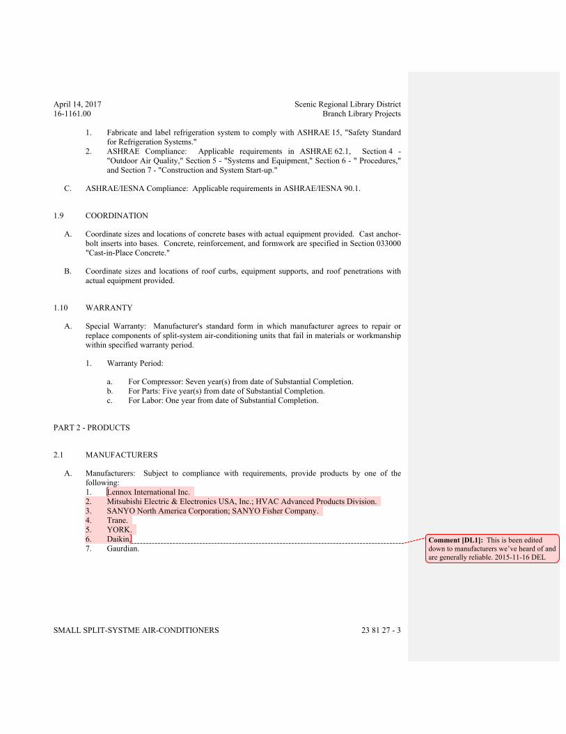
April 14, 2017 Scenic Regional Library District
16-1161.00 Branch Library Projects
SMALL SPLIT-SYSTME AIR-CONDITIONERS 23 81 27 - 3
1. Fabricate and label refrigeration system to comply with ASHRAE 15, "Safety Standard
for Refrigeration Systems."
2. ASHRAE Compliance: Applicable requirements in ASHRAE 62.1, Section 4 -
"Outdoor Air Quality," Section 5 - "Systems and Equipment," Section 6 - " Procedures,"
and Section 7 - "Construction and System Start-up."
C. ASHRAE/IESNA Compliance: Applicable requirements in ASHRAE/IESNA 90.1.
1.9 COORDINATION
A. Coordinate sizes and locations of concrete bases with actual equipment provided. Cast anchor-
bolt inserts into bases. Concrete, reinforcement, and formwork are specified in Section 033000
"Cast-in-Place Concrete."
B. Coordinate sizes and locations of roof curbs, equipment supports, and roof penetrations with
actual equipment provided.
1.10 WARRANTY
A. Special Warranty: Manufacturer's standard form in which manufacturer agrees to repair or
replace components of split-system air-conditioning units that fail in materials or workmanship
within specified warranty period.
1. Warranty Period:
a. For Compressor: Seven year(s) from date of Substantial Completion.
b. For Parts: Five year(s) from date of Substantial Completion.
c. For Labor: One year from date of Substantial Completion.
PART 2 - PRODUCTS
2.1 MANUFACTURERS
A. Manufacturers: Subject to compliance with requirements, provide products by one of the
following:
1. Lennox International Inc.
2. Mitsubishi Electric & Electronics USA, Inc.; HVAC Advanced Products Division.
3. SANYO North America Corporation; SANYO Fisher Company.
4. Trane.
5. YORK.
6. Daikin.
7. Gaurdian.Comment [DL1]: This is been edited
down to manufacturers we’ve heard of and
are generally reliable. 2015-11-16 DEL
April 14, 2017 Scenic Regional Library District
16-1161.00 Branch Library Projects
SMALL SPLIT-SYSTME AIR-CONDITIONERS 23 81 27 - 4
2.2 SYSTEM DESIGN
A. Split-System Heating and Cooling Units: Self-contained, packaged, matched factory-engineered
and assembled, pre-wired indoor and outdoor units; UL listed.
a. Heating and Cooling: Air-source electric heat pump located in outdoor unit with
evaporator; auxiliary electric heat.
b. Cooling: Outdoor electric condensing unit with evaporator coil in central ducted
indoor unit.
c. Provide refrigerant lines internal to units and between indoor and outdoor units,
factory cleaned, dried, pressurized and sealed, with insulated suction line.
B. Performance Requirements: See Drawings for additional requirements.
2.3 INDOOR UNITS FOR DUCTED SYSTEMS
A. Indoor Units: Self-contained, packaged, factory assembled, pre-wired unit consisting of cabinet,
supply fan, heating and cooling element(s), controls, and accessories; wired for single power
connection with control transformer.
1. Air Flow Configuration: Counterflow, with additional steel base.
2. Cabinet: Steel with baked enamel finish, easily removed and secured access doors with
safety interlock switches, glass fiber insulation with reflective liner.
B. Supply Fan: Centrifugal type rubber mounted with direct or belt drive with adjustable variable
pitch motor pulley.
1. Motor: NEMA MG 1; 1750 rpm single speed, permanently lubricated, hinge mounted.
2. Motor Electrical Characteristics:
C. Air Filters: 1 inch thick glass fiber, disposable type arranged for easy replacement.
D. Evaporator Coils: Copper tube aluminum fin assembly, stainless steel or polymer drain pan
sloped in all directions to drain, drain connection, refrigerant piping connections, restricted
distributor or thermostatic expansion valve.
1. Construction and Ratings: In accordance with AHRI 210/240 and UL listed.
2. Manufacturers: System manufacturer.
2.4 OUTDOOR UNITS
A. Outdoor Units: Self-contained, packaged, pre-wired unit consisting of cabinet, with compressor
and condenser.
1. Comply with AHRI 210.
2. Refrigerant: R-410A.
3. Cabinet: Galvanized steel with baked enamel finish, easily removed and secured access
doors with safety interlock switches, glass fiber insulation with reflective liner.
4. Construction and Ratings: In accordance with AHRI 210/240 with testing in accordance
with ASHRAE Std 23.1 and UL 207.
5. Sound Rating: 69 dBA, when measured in accordance with AHRI 270.
B. Compressor: AHRI 520; scroll, inverter, resiliently mounted integral with condenser, with
positive lubrication, crankcase heater, high pressure control, motor overload protection, service
April 14, 2017 Scenic Regional Library District
16-1161.00 Branch Library Projects
SMALL SPLIT-SYSTME AIR-CONDITIONERS 23 81 27 - 5
valves and drier. Provide time delay control to prevent short cycling. Inverter for compressor
motor speed control
C. Air Cooled Condenser: ARI 520; Aluminum fin and copper tube coil, with direct drive axial
propeller fan resiliently mounted, galvanized fan guard.
1. Condenser Fans: Direct-drive propeller type.
2. Condenser Fan Motor: Enclosed, 1-phase type, permanently lubricated.
D. Coil: Air-cooled, aluminum fins bonded to copper tubes.
E. Accessories: Filter drier, high pressure switch (manual reset), low pressure switch (automatic
reset), service valves and gage ports, thermometer well (in liquid line).
1. Provide thermostatic expansion valves.
2. Provide heat pump reversing valves.
F. Operating Controls:
1. Control by room thermostat to maintain room temperature setting.
2. Low Ambient Kit: Provide refrigerant pressure switch to cycle condenser fan on when
condenser refrigerant pressure is above 285 psig and off when pressure drops below 140
psig for operation to 0 degrees F.
2.5 ACCESSORY EQUIPMENT
A. Room Thermostat: Wall-mounted, electric solid state microcomputer based room thermostat
with remote sensor to maintain temperature setting; low-voltage; with following features:
1. System selector switch (heat-off-cool) and fan control switch (auto-on).
2. Automatic switching from heating to cooling.
3. Preferential rate control to minimize overshoot and deviation from setpoint.
4. Set-up for four separate temperatures per day.
5. Instant override of setpoint for continuous or timed period from one hour to 31 days.
6. Short cycle protection.
7. Programming based on weekdays, Saturday and Sunday.
8. Selection features including degree F or degree C display, 12 or 24 hour clock, keyboard
disable, remote sensor, fan on-auto.
9. Battery replacement without program loss.
10. Thermostat display:
a. Time of day.
b. Actual room temperature.
c. Programmed temperature.
d. System mode indication: heating, cooling, fan auto, off, and on, auto or on, off.
2.6 ACCESSORIES
A. Refrigerant Line Kits: Soft-annealed copper suction and liquid lines factory cleaned, dried,
pressurized, and sealed; factory-insulated suction line with flared fittings at both ends.
B. Drain Hose: For condensate.
April 14, 2017 Scenic Regional Library District
16-1161.00 Branch Library Projects
SMALL SPLIT-SYSTME AIR-CONDITIONERS 23 81 27 - 6
PART 3 - EXECUTION
3.1 INSTALLATION
A. Install units level and plumb.
B. Install evaporator-fan components using manufacturer's standard mounting devices securely
fastened to building structure.
C. Install roof-mounted, compressor-condenser components on equipment supports specified in
Section 077200 "Roof Accessories." Anchor units to supports with removable, cadmium-plated
fasteners.
D. Install in accordance with manufacturer’s instructions and requirements of local authorities
having jurisdiction.
E. Install in accordance with NFPA 90A and NFPA 90B.
F. Install refrigeration systems in accordance with ASHRAE standard 15.
G. Equipment Mounting:
1. Install ground-mounted, compressor-condenser components on cast-in-place concrete
equipment base(s). Comply with requirements for equipment bases and foundations
specified in Section 033000 "Cast-in-Place Concrete."
2. Install ground-mounted, compressor-condenser components on polyethylene mounting
base.
3. Comply with requirements for vibration isolation and seismic control devices specified in
Section 230548 "Vibration and Seismic Controls for HVAC."
4. Comply with requirements for vibration isolation devices specified in Section 230548.13
"Vibration Controls for HVAC."
H. Install and connect precharged refrigerant tubing to component's quick-connect fittings. Install
tubing to allow access to unit.
3.2 CONNECTIONS
A. Piping installation requirements are specified in other Sections. Drawings indicate general
arrangement of piping, fittings, and specialties.
B. Where piping is installed adjacent to unit, allow space for service and maintenance of unit.
C. Duct Connections: Duct installation requirements are specified in Section 233113 "Metal
Ducts." Drawings indicate the general arrangement of ducts. Connect supply and return ducts
to split-system air-conditioning units with flexible duct connectors. Flexible duct connectors
are specified in Section 233300 "Air Duct Accessories."
April 14, 2017 Scenic Regional Library District
16-1161.00 Branch Library Projects
SMALL SPLIT-SYSTME AIR-CONDITIONERS 23 81 27 - 7
3.3 FIELD QUALITY CONTROL
A. Manufacturer's Field Service: Engage a factory-authorized service representative to inspect,
test, and adjust components, assemblies, and equipment installations, including connections.
B. Perform tests and inspections.
1. Manufacturer's Field Service: Engage a factory-authorized service representative to
inspect components, assemblies, and equipment installations, including connections, and
to assist in testing.
C. Tests and Inspections:
1. Leak Test: After installation, charge system and test for leaks. Repair leaks and retest
until no leaks exist.
2. Operational Test: After electrical circuitry has been energized, start units to confirm
proper motor rotation and unit operation.
3. Test and adjust controls and safeties. Replace damaged and malfunctioning controls and
equipment.
D. Remove and replace malfunctioning units and retest as specified above.
E. Prepare test and inspection reports.
3.4 STARTUP SERVICE
A. Engage a factory-authorized service representative to perform startup service.
1. Complete installation and startup checks according to manufacturer's written instructions.
3.5 DEMONSTRATION
A. Engage a factory-authorized service representative to train Owner's maintenance personnel to
adjust, operate, and maintain units.
END OF SECTION 238126
April 14, 2017 Scenic Regional Library District
16-1161.00 Branch Library Projects
COMMON WORK RESULTS FOR ELECTRICAL 260521 - 1
SECTION 260521 - COMMON WORK RESULTS FOR ELECTRICAL
PART 1 - GENERAL
1.1 RELATED DOCUMENTS
A. Drawings and general provisions of the Contract, including General and Supplementary
Conditions and Division 1 Specification Sections, apply to this Section.
1.2 SUMMARY
A. Contractor Shall Provide:
1. Coordination with other sub-contractors on project.
2. Sleeves for raceways and cables.
3. Common electrical installation requirements.
1.3 SUBMITTALS
A. Product Data: For sleeve seals.
B. Work with other contractors on project to obtain installation instructions for equipment to verify
proper rough-in and equipment locations.
1.4 COORDINATION
A. Coordinate arrangement, mounting, and support of electrical equipment:
1. To allow maximum possible headroom unless specific mounting heights that reduce
headroom are indicated.
2. To provide for ease of disconnecting the equipment with minimum interference to other
installations.
3. To allow right of way for piping and conduit installed at required slope.
4. So connecting raceways, cables, and cable trays will be clear of obstructions and of the
working and access space of other equipment.
B. Coordinate installation of required supporting devices and set sleeves in cast-in-place concrete,
masonry walls, and other structural components as they are constructed.
C. Coordinate location of access panels and doors for electrical items that are behind finished
surfaces or otherwise concealed.
D. Some system will require the Electrical Contractor to receive components and install them. It is
the Electrical Contractor’s responsibility to become familiar with these installations and to
coordinate with the supplying contractor.
PART 2 - PRODUCTS
2.1 SLEEVES FOR RACEWAYS AND CABLES
A. Steel Pipe Sleeves: ASTM A 53/A 53M, Type E, Grade B, Schedule 40, galvanized steel, plain
ends.
April 14, 2017 Scenic Regional Library District
16-1161.00 Branch Library Projects
COMMON WORK RESULTS FOR ELECTRICAL 260521 - 2
2.2 SLEEVE SEALS
A. Description: Modular sealing device, designed for field assembly, to fill annular space between
sleeve and raceway or cable.
1. Manufacturers: Subject to compliance with requirements, available manufacturers
offering products that may be incorporated into the Work include, but are not limited to,
the following:
a. Advance Products & Systems, Inc.
b. Calpico, Inc.
c. Metraflex Co.
d. Pipeline Seal and Insulator, Inc.
2. Sealing Elements: EPDM or NBR interlocking links shaped to fit surface of cable or
conduit. Include type and number required for material and size of raceway or cable.
3. Pressure Plates: Plastic, Carbon steel or Stainless steel. Include two for each sealing
element.
4. Connecting Bolts and Nuts: Carbon steel with corrosion-resistant coating or Stainless
steel of length required to secure pressure plates to sealing elements. Include one for
each sealing element.
2.3 GROUT
A. Nonmetallic, Shrinkage-Resistant Grout: ASTM C 1107, factory-packaged, nonmetallic
aggregate grout, noncorrosive, non-staining, mixed with water to consistency suitable for
application and a 30-minute working time.
PART 3 - EXECUTION
3.1 COMMON REQUIREMENTS FOR ELECTRICAL INSTALLATION
A. Measure indicated mounting heights to bottom of unit for suspended items and to center of unit
for wall-mounting items.
B. Headroom Maintenance: If mounting heights or other location criteria are not indicated,
arrange and install components and equipment to provide maximum possible headroom
consistent with these requirements.
C. Equipment: Install to facilitate service, maintenance, and repair or replacement of components
of both electrical equipment and other nearby installations. Connect in such a way as to
facilitate future disconnecting with minimum interference with other items in the vicinity.
D. Right of Way: Give to piping systems installed at a required slope.
3.2 SLEEVE INSTALLATION FOR ELECTRICAL PENETRATIONS
A. Electrical penetrations occur when raceways penetrate concrete slabs, concrete or masonry
walls, or fire-rated floor and wall assemblies.
April 14, 2017 Scenic Regional Library District
16-1161.00 Branch Library Projects
COMMON WORK RESULTS FOR ELECTRICAL 260521 - 3
B. Concrete Slabs and Walls: Install sleeves for penetrations unless core-drilled holes or formed
openings are used. Install sleeves during erection of slabs and walls.
C. Fire-Rated Assemblies: Install sleeves for penetrations of fire-rated floor and wall assemblies
unless openings compatible with firestop system used are fabricated during construction of floor
or wall. Floor penetrations and penetrations between the Office Area into the Apparatus Bay
shall be fire rated.
D. Cut sleeves to length for mounting flush with both surfaces of walls.
E. Extend sleeves installed in floors 2 inches above finished floor level.
F. Size pipe sleeves to provide 1/4-inch annular clear space between sleeve and raceway, unless
indicated otherwise.
G. Seal space outside of sleeves with grout for penetrations of concrete and masonry
1. Promptly pack grout solidly between sleeve and wall so no voids remain. Tool exposed
surfaces smooth; protect grout while curing.
H. Fire-Rated-Assembly Penetrations: Maintain fire rating of walls, partitions, ceilings, and floors
at raceway and cable penetrations. Install sleeves and seal raceway penetration sleeves with
firestop materials. Cables shall not pass through fire rated walls, use only building wire in
conduit for these locations.
I. Roof-Penetration Sleeves: Seal penetration of individual raceways flexible boot-type flashing
units applied in coordination with roofing work.
J. Aboveground, Exterior-Wall Penetrations: Seal penetrations using steel, cast-iron pipe sleeves
and mechanical sleeve seals. Select sleeve size to allow for 1-inch annular clear space between
pipe and sleeve for installing mechanical sleeve seals.
K. Underground, Exterior-Wall Penetrations: Install cast-iron pipe sleeves. Size sleeves to allow
for 1-inch annular clear space between raceway or cable and sleeve for installing mechanical
sleeve seals.
3.3 SLEEVE-SEAL INSTALLATION
A. Install to seal exterior wall penetrations.
B. Use type and number of sealing elements recommended by manufacturer for raceway or cable
material and size. Position raceway or cable in center of sleeve. Assemble mechanical sleeve
seals and install in annular space between raceway or cable and sleeve. Tighten bolts against
pressure plates that cause sealing elements to expand and make watertight seal.
3.4 FIRESTOPPING
A. Apply firestopping to penetrations of fire-rated floor and wall assemblies for electrical
installations to restore original fire-resistance rating of assembly. Firestopping materials and
installation requirements are specified in Division 7 Section "Through-Penetration Firestop
Systems."
April 14, 2017 Scenic Regional Library District
16-1161.00 Branch Library Projects
COMMON WORK RESULTS FOR ELECTRICAL 260521 - 4
3.5 EQUIPMENT CONNECTION
A. Provide electrical connection to equipment specified in other sections that require electrical
connection. Coordinate exact requirements with other contracts. Make the necessary
connections to make equipment fully operational.
END OF SECTION 260521
April 14, 2017 Scenic Regional Library District
16-1161.00 Branch Library Projects
BUILDING WIRE & CABLE 260523 - 1
SECTION 260523 -BUILDING WIRE AND CABLE
PART 1 - GENERAL
1.1 WORK INCLUDES
A. Contractor Provide:
1. Building wire and cable as shown on drawings or specified including feeders, branch
circuit power, lighting systems and other systems specified.
2. Wiring connectors and connections.
1.2 REFERENCES
A. ANSI/NFPA 70 - National Electrical Code.
1.3 QUALIFICATIONS
A. Manufacturer: Company specializing in manufacturing products specified in this Section
with minimum 3 years experience.
1.4 SUBMITTALS
A. Submit shop drawings and product data.
B. Indicate material specifications, dimensions, capacities and color coding.
C. Provide product data for all wire and cable.
D. Submit manufacturers’ installation instructions.
1.5 REGULATORY REQUIREMENTS
A. Conform to requirements of ANSI/NFPA 70.
B. Furnish products listed and classified by Underwriters Laboratories, Inc. or testing firm
acceptable to authority having jurisdiction as suitable for purpose specified and shown.
1.6 REFERENCES
A. If conflict between referenced standards and contract documents, notify Architect/Engineer
immediately. Do not proceed with the work until the Architect/Engineer issues instructions.
B. National Electrical Manufacturers Association (NEMA):
1. WC 3 - Rubber-Insulated Wire and Cable for the Transmission and Distribution of
Electrical Energy.
2. WC 5 - Thermoplastic-Insulated Wire and Cable for the Transmission and
Distribution of Electrical Energy.
3. WC 7 - Cross-Linked-Thermosetting-Polyethylene-Insulated Wire and Cable for the
Transmission and Distribution of Electrical Energy.
April 14, 2017 Scenic Regional Library District
16-1161.00 Branch Library Projects
BUILDING WIRE & CABLE 260523 - 2
C. National Fire Protection Association (NFPA): NFPA 70- National Electrical Code.
D. Underwriters laboratories, Inc. (UL): Listed and labeled materials.
E. Manufacturers’ Catalogs: Specified manufacturers’ catalogs are incorporated by reference
to same force and effect as if repeated herein full.
1.7 PROJECT CONDITIONS
A. Verify that field measurements are as shown on Drawings.
B. Conductors shall be copper.
C. Where wire and cable routing is not shown, and destination only is indicated, determine
exact routing and lengths required.
1.8 COORDINATION
A. Determine required separation between cable and other work.
B. Determine cable routing to avoid interference with other work.
PART 2 - PRODUCTS
2.1 BUILDING WIRE AND CABLE
A. Thermoplastic insulated building wire: NEMA WC 5, UL-83 ICEA S-61-402 or S-66-524.
B. Metal Clad Cable: Comply with NEMA WC 70 for metal-clad cable, Type MC with
insulated ground wire. Conductors shall be THHN/THWN copper stranded enclosed in an
overall armor of smooth (tube) metallic sheath, corrugated metallic sheath, and interlocking
metal tape armor. Armor can be either galvanized steel or solid aluminum. Aluminum
interlocked sheathing is not acceptable. MC cable may only be installed if allowed by
local code.
C. Feeders larger than 250 MCM: Copper, stranded conductor, 600volt insulation
THHN/THWN.
D. Feeders and branch circuits larger than 8 AWG and smaller than 250 MCM: Copper,
stranded conductor, 600volt insulation THHN/THWN.
E. Feeders and branch circuits 8 AWG and smaller: Copper conductor, 600volt insulation
THHN/THWN, solid or stranded conductor.
F. Control Circuits: Copper, stranded conductor, 600volt insulation TFFN, THW, or
THHN/THWN.
G. Low voltage wire for lighting controls: #14 plenum rated. 3 conductor cable, or as
specified by lighting controls manufacturer.
April 14, 2017 Scenic Regional Library District
16-1161.00 Branch Library Projects
BUILDING WIRE & CABLE 260523 - 3
H. Color code conductors as specified in Section 260553 - Electrical Identification.
April 14, 2017 Scenic Regional Library District
16-1161.00 Branch Library Projects
BUILDING WIRE & CABLE 260523 - 4
2.2 JOINTS AND SPLICES
A. Make terminations, taps and splices with an indent type pressure connector with insulating
cover for 8 AWG and smaller.
B. Instead of indent type connectors insulated spring compression connectors may be used for
10 AWG and smaller.
C. Use mechanical compression or bolted type connector for 6 AWG or larger. Cover
connector with insulating type or heat shrinkable insulation equivalent to 150% conductor
insulation.
2.3 WIRE PULLING LUBRICANT
A. Pulling lubricant shall be a UL listed, water-based, polymer solution. Lubricants
containing waxes or soaps are not acceptable.
B. The lubricant shall be compatible with the cable insulation and shall not cause any
premature deterioration of the insulating material. When used on high voltage cable, the
lubricant shall not affect the volume resistance of any semi-conducting jacket or insulation
shield present.
C. Dried residue from lubricant shall not become tacky or gum-up. Cables shall remain able
to pull after lubricant has dried.
D. The lubricant shall be as approved by the cable manufacturer for use with their cables.
E. Acceptable Manufacturers/Products:
1. American Colloid/Poly-X.
2. American Polywater/Polywater J.
3. ARNCO/Hydra-Lube.
4. Buchanan/Quick Slip.
5. Condux/Super-Lube.
6. Ideal/Aqua-Gel.
PART 3 - EXECUTION
3.1 EXAMINATION
A. Verify that interior of building has been protected from weather.
B. Verify that mechanical work likely to damage wire and cable has been completed.
3.2 PREPARATION
A. Completely and thoroughly swab raceway before installing wire.
3.3 WIRING METHODS
A. Concealed Dry Interior Locations: Use building wire, in raceway or metal clad cable.
April 14, 2017 Scenic Regional Library District
16-1161.00 Branch Library Projects
BUILDING WIRE & CABLE 260523 - 5
Provide building wire in raceway for all homeruns. Homeruns begin within 15 feet of first
device served by the branch circuit.
B. Exposed Dry Interior Locations: Use only building wire, in raceway.
C. Above Accessible Ceilings: Use building wire, in raceway or metal clad cable. Provide
building wire in raceway for al homeruns.
D. Wet or Damp Interior Locations: Use only building wire, in raceway.
E. Exterior Locations: Use only building wire, in raceway.
F. Underground Installations: Use only building wire, in raceway.
G. Low voltage wire shall be installed in conduit in non accessible locations and where
exposed. Plenum rated cable can be installed above accessible ceilings supported at 5 foot
intervals or 1 foot from transition.
3.4 INSTALLATION
A. Install products in accordance with manufacturers’ instructions.
B. Use conductor not smaller than 12 AWG for power and lighting circuits.
C. Use conductor not smaller than 14 AWG for control circuits.
D. Use 10 AWG conductors for 20 ampere, 120volt branch circuits longer than 75 feet.
E. Use 10 AWG conductors for 20 ampere, 277volt branch circuits longer than 200 feet.
F. Pull all conductors into raceway at same time.
G. Use suitable wire pulling lubricant for building wire 4 AWG and larger.
H. Protect exposed cable from damage.
I. Use suitable cable fittings and connectors.
J. Neatly train and lace wiring inside boxes, equipment, and panelboards.
K. Clean conductor surfaces before installing lugs and connectors.
L. Make splices, taps and terminations to carry full ampacity of conductors with no
perceivable temperature rise.
M. Place an equal number of conductors for each phase of a circuit in same raceway or cable.
N. Splice only in accessible junction, outlet boxes, cable tray or surface metal raceway.
O. Make conductors equal lengths for parallel circuits.
April 14, 2017 Scenic Regional Library District
16-1161.00 Branch Library Projects
BUILDING WIRE & CABLE 260523 - 6
P. Branch circuits shall not share neutral conductors.
Q. Provide dedicated neutral conductor for each circuit from the Dimmer Equipment.
R. MC cable shall not run exposed in finished spaces.
S. MC cable shall not be used for home runs to/from panelboards. A home run begins within
15 feet of first device or fixture in a branch circuit.
3.5 IDENTIFICATION
A. Identify wire and cable under provisions of Section 260553.
B. Identify each conductor with its circuit number or other designation.
3.6 FIELD QUALITY CONTROL
A. Inspect wire and cable for physical damage and proper connection.
B. Measure tightness of bolted connections and compare torque measurements with
manufacturer's recommended values.
C. Verify continuity of each branch circuit conductor.
END OF SECTION 260523
April 14, 2017 Scenic Regional Library District
16-1161.00 Branch Library Projects
GROUNDING & BONDING 260526 - 1
SECTION 260526 – GROUNDING AND BONDING
PART 1 - GENERAL
1.1 SECTION INCLUDES
A. Contractor Provide:
1. Grounding electrode system.
2. Grounding for branch circuits and feeders.
3. Grounding for Control Circuitry.
1.2 DEFINITIONS
A. Equipment Ground Conductor:
1. The conductor that connects the noncurrent-carrying metal parts of equipment to the
grounding electrode system or ground bus.
B. Grounding Electrode Conductor:
1. The conductor that connects the ground electrodes to the grounded circuit conductor
and/or the equipment grounding conductor.
C. Grounded Circuit Conductor:
1. A circuit conductor, usually the neutral, that is intentionally connected to ground.
D. Made Electrode:
1. Any item, such as a ground rod, which is solely used to provide a ground connection.
1.3 QUALITY ASSURANCE
A. Regulatory Requirements:
1. Comply with National Electric Code.
2. Comply with Public Authorities having jurisdiction.
B. Source Quality Control
1. The authority having jurisdiction will inspect the installation for compliance with
governing codes.
1.4 REFERENCES. Specified references, or cited portions thereof, current at date of bidding
documents unless otherwise specified, govern the work. In conflict between referenced
standards and contract documents, notify Architect/Engineer immediately. Confirm notification
in writing. Do not proceed with the work until the Architect/Engineer issues written instructions.
A. National Fire Protection Association (NFPA): NFPA 70 - National electrical Code (NEC).
April 14, 2017 Scenic Regional Library District
16-1161.00 Branch Library Projects
GROUNDING & BONDING 260526 - 2
B. Furnish products listed and classified by a Nationally Recognized Testing Laboratory
(NRTL) as suitable for purpose specified and shown.
C. Manufacturers' Catalogs: Specification manufacturers' catalogs are incorporated by
reference to same force and effect as if repeated herein in full.
D. ANSI C2 - National Electrical Safety code.
1.5 SUBMITTALS
A. Submit Product Data: Provide data for grounding electrodes and connections.
B. Submit Test Reports: Indicate overall resistance to ground in accordance with section
260553.
PART 2 - PRODUCTS
2.1 MATERIALS
A. Connections:
1. All rod to rod, rod to cable, cable to cable, and cable to structural steel connections
shall be by an approved exothermic or mechanical weld process.
2. Connections to metallic pipe may be by either exothermic weld or approved UL
listed ground clamp.
3. Any splices to ground electrode conductors shall be exothermic weld only.
B. Terminating Lugs:
1. Exothermic weld, mechanical weld, or crimp compression type.
C. Wire:
1. Equipment grounding conductors shall be insulated. Insulation shall be 600 volt,
same type as phase conductors, green in color. Use yellow tracer stripes to
distinguish different grounding systems.
2. Ground electrode conductors shall be bare annealed copper.
D. Rod Electrode:
1. Material: Copper-Clad Steel.
2. Diameter: 3/4 inch.
3. Length: 10 feet.
PART 3 - EXECUTION
3.1 INSTALLATION
April 14, 2017 Scenic Regional Library District
16-1161.00 Branch Library Projects
GROUNDING & BONDING 260526 - 3
A. Provide a separate equipment grounding conductor in all feeders and branch circuits, unless
indicated otherwise on the drawings. Terminate each end on grounding lug, bus or busing.
B. Bond all raceways, cabinet enclosures, and non-current carrying parts of equipment to
grounding system. Bond raceways such that a continuous path for current flow is
maintained.
C. Separately Derived Systems:
1. Bond neutral of transformers to metal equipment enclosure or frame. Provide
connection from enclosure to nearest metallic water pipe or structural steel member
and to feeder ground.
D. Bond all grounding systems together. Size of bonding conductor shall be at least the size of
the largest grounding electrode conductor.
E. Ground electrode conductors shall be run exposed whenever possible. If conduit is needed
for protection, Schedule 40 PVC conduit shall be used. All cable clamps and conduit
supports shall be designed so they do NOT totally encircle conduit or cable in metal.
F. All connections to the metallic water piping shall be made using either approved ground
clamps or exothermic welds. All connections to structural steel shall be by the exothermic
weld process.
3.2 SERVICE ENTRANCE GROUNDING
A. Ground electrical service neutral at service entrance equipment and at the generator.
Connect main grounding electrode conductors to water piping with an approved ground
clamp or exothermic weld. Make connections to flanged piping at street side of flange.
Provide bonding jumper around water meter. Bond to ground ring as indicated on the
drawings and at generator.
B. Provide grounding connection to the building foundation re-enforcement.
3.3 DATA SYSTEM GROUNDING
A. Provide grounding for data/communication system as indicated on the drawings. These
grounding systems shall be solidly connected to the building main ground.
3.4 FIELD QUALITY CONTROL
A. Field inspection and testing will be performed under provisions of section 260553.
B. Inspect grounding and bonding system conductors and connections for tightness and proper
installation.
C. Use suitable test instrument to measure resistance to ground of system. Perform testing in
accordance with test instrument manufacturer's recommendations using the fall-of-potential
method.
April 14, 2017 Scenic Regional Library District
16-1161.00 Branch Library Projects
GROUNDING & BONDING 260526 - 4
D. Resistance measurement shall be from the system neutral connection at the service entrance
to a convenient ground reference point. The ground reference point should be located to
minimize the effects of other existing grounding electrodes.
E. Ground resistance shall not exceed 10 OHMS. When resistance exceeds 5 OHMS, one of
the following measures shall be taken to reduce the ground resistance:
1. Drive and bond additional ground rods at two rod length intervals.
2. Treat the soil in the vicinity of the electrode with metallic salts.
3. Remove soil from around the electrode and replace with bentonite.
4. Use a UL approved electrolytic chemical ground rod.
F. All resistance tests shall be taken no sooner than 48 hours after a measurable rainfall.
END OF SECTION 260526
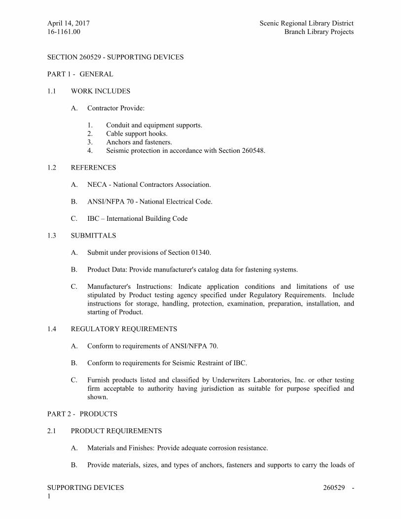
April 14, 2017 Scenic Regional Library District
16-1161.00 Branch Library Projects
SUPPORTING DEVICES 260529 -
1
SECTION 260529 - SUPPORTING DEVICES
PART 1 - GENERAL
1.1 WORK INCLUDES
A. Contractor Provide:
1. Conduit and equipment supports.
2. Cable support hooks.
3. Anchors and fasteners.
4. Seismic protection in accordance with Section 260548.
1.2 REFERENCES
A. NECA - National Contractors Association.
B. ANSI/NFPA 70 - National Electrical Code.
C. IBC – International Building Code
1.3 SUBMITTALS
A. Submit under provisions of Section 01340.
B. Product Data: Provide manufacturer's catalog data for fastening systems.
C. Manufacturer's Instructions: Indicate application conditions and limitations of use
stipulated by Product testing agency specified under Regulatory Requirements. Include
instructions for storage, handling, protection, examination, preparation, installation, and
starting of Product.
1.4 REGULATORY REQUIREMENTS
A. Conform to requirements of ANSI/NFPA 70.
B. Conform to requirements for Seismic Restraint of IBC.
C. Furnish products listed and classified by Underwriters Laboratories, Inc. or other testing
firm acceptable to authority having jurisdiction as suitable for purpose specified and
shown.
PART 2 - PRODUCTS
2.1 PRODUCT REQUIREMENTS
A. Materials and Finishes: Provide adequate corrosion resistance.
B. Provide materials, sizes, and types of anchors, fasteners and supports to carry the loads of
April 14, 2017 Scenic Regional Library District
16-1161.00 Branch Library Projects
SUPPORTING DEVICES 260529 -
2
equipment and conduit. Consider weight of wire in conduit when selecting products.
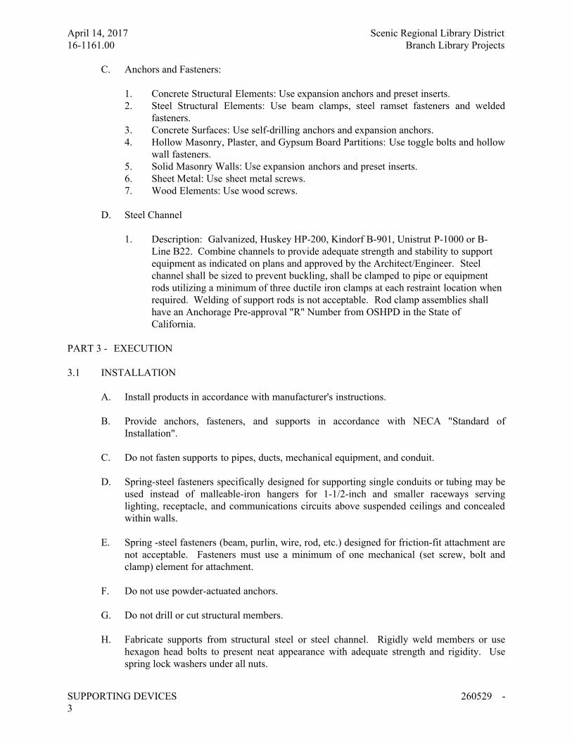
April 14, 2017 Scenic Regional Library District
16-1161.00 Branch Library Projects
SUPPORTING DEVICES 260529 -
3
C. Anchors and Fasteners:
1. Concrete Structural Elements: Use expansion anchors and preset inserts.
2. Steel Structural Elements: Use beam clamps, steel ramset fasteners and welded
fasteners.
3. Concrete Surfaces: Use self-drilling anchors and expansion anchors.
4. Hollow Masonry, Plaster, and Gypsum Board Partitions: Use toggle bolts and hollow
wall fasteners.
5. Solid Masonry Walls: Use expansion anchors and preset inserts.
6. Sheet Metal: Use sheet metal screws.
7. Wood Elements: Use wood screws.
D. Steel Channel
1. Description: Galvanized, Huskey HP-200, Kindorf B-901, Unistrut P-1000 or B-
Line B22. Combine channels to provide adequate strength and stability to support
equipment as indicated on plans and approved by the Architect/Engineer. Steel
channel shall be sized to prevent buckling, shall be clamped to pipe or equipment
rods utilizing a minimum of three ductile iron clamps at each restraint location when
required. Welding of support rods is not acceptable. Rod clamp assemblies shall
have an Anchorage Pre-approval "R" Number from OSHPD in the State of
California.
PART 3 - EXECUTION
3.1 INSTALLATION
A. Install products in accordance with manufacturer's instructions.
B. Provide anchors, fasteners, and supports in accordance with NECA "Standard of
Installation".
C. Do not fasten supports to pipes, ducts, mechanical equipment, and conduit.
D. Spring-steel fasteners specifically designed for supporting single conduits or tubing may be
used instead of malleable-iron hangers for 1-1/2-inch and smaller raceways serving
lighting, receptacle, and communications circuits above suspended ceilings and concealed
within walls.
E. Spring -steel fasteners (beam, purlin, wire, rod, etc.) designed for friction-fit attachment are
not acceptable. Fasteners must use a minimum of one mechanical (set screw, bolt and
clamp) element for attachment.
F. Do not use powder-actuated anchors.
G. Do not drill or cut structural members.
H. Fabricate supports from structural steel or steel channel. Rigidly weld members or use
hexagon head bolts to present neat appearance with adequate strength and rigidity. Use
spring lock washers under all nuts.
April 14, 2017 Scenic Regional Library District
16-1161.00 Branch Library Projects
SUPPORTING DEVICES 260529 -
4
I. Install surface-mounted cabinets and panel boards with minimum of four anchors.
J. In wet and damp locations use steel channel supports to stand cabinets and panel boards
one inch off wall.
K. Use sheet metal channel to bridge studs above and below cabinets and panel boards
recessed in hollow partitions.
L. Touch-up any material damaged during construction.
M. Provide support to meet seismic requirements. Where necessary provide the services of a
registered structural engineer to calculate and engineer support systems or restraints.
Submit to Architect/Engineer results and documents (sealed drawings) for any such
systems or restraints.
N. Provide seismic protection in accordance with Section 260548.
END OF SECTION 260529
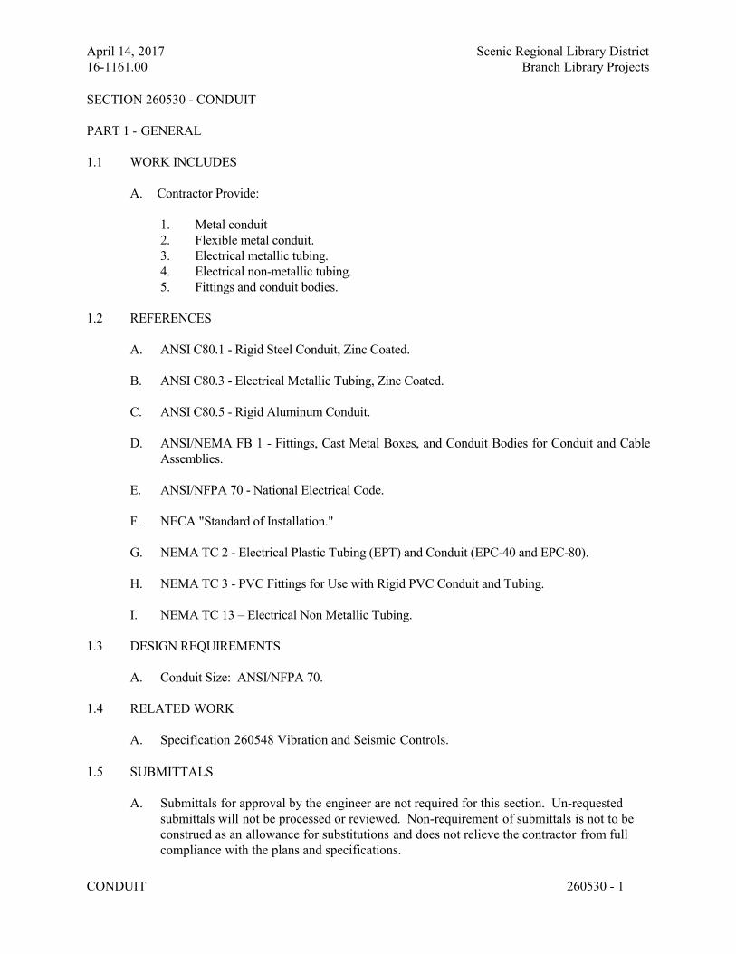
April 14, 2017 Scenic Regional Library District
16-1161.00 Branch Library Projects
CONDUIT 260530 - 1
SECTION 260530 - CONDUIT
PART 1 - GENERAL
1.1 WORK INCLUDES
A. Contractor Provide:
1. Metal conduit
2. Flexible metal conduit.
3. Electrical metallic tubing.
4. Electrical non-metallic tubing.
5. Fittings and conduit bodies.
1.2 REFERENCES
A. ANSI C80.1 - Rigid Steel Conduit, Zinc Coated.
B. ANSI C80.3 - Electrical Metallic Tubing, Zinc Coated.
C. ANSI C80.5 - Rigid Aluminum Conduit.
D. ANSI/NEMA FB 1 - Fittings, Cast Metal Boxes, and Conduit Bodies for Conduit and Cable
Assemblies.
E. ANSI/NFPA 70 - National Electrical Code.
F. NECA "Standard of Installation."
G. NEMA TC 2 - Electrical Plastic Tubing (EPT) and Conduit (EPC-40 and EPC-80).
H. NEMA TC 3 - PVC Fittings for Use with Rigid PVC Conduit and Tubing.
I. NEMA TC 13 – Electrical Non Metallic Tubing.
1.3 DESIGN REQUIREMENTS
A. Conduit Size: ANSI/NFPA 70.
1.4 RELATED WORK
A. Specification 260548 Vibration and Seismic Controls.
1.5 SUBMITTALS
A. Submittals for approval by the engineer are not required for this section. Un-requested
submittals will not be processed or reviewed. Non-requirement of submittals is not to be
construed as an allowance for substitutions and does not relieve the contractor from full
compliance with the plans and specifications.
April 14, 2017 Scenic Regional Library District
16-1161.00 Branch Library Projects
CONDUIT 260530 - 2
1.6 PROJECT RECORD DOCUMENTS
A. Submit Project Record Documents.
B. Accurately record actual routing of conduits.
1.7 REGULATORY REQUIREMENTS
A. Conform to requirements of ANSI/NFPA 70.
B. Furnish products listed and classified by Underwriters Laboratories, Inc. or other testing firm
acceptable to authority having jurisdiction as suitable for purpose specified and shown.
1.8 DELIVERY, STORAGE, AND HANDLING
A. Accept conduit on site. Inspect for damage.
B. Protect conduit from corrosion and entrance of debris by storing above grade. Provide
appropriate covering.
1.9 PROJECT CONDITIONS
A. Verify that field measurements are as shown on Drawings.
B. Verify routing and termination locations of conduit prior to rough-in.
C. Provide conduit as required to complete wiring system.
PART 2 - PRODUCTS
2.1 CONDUIT REQUIREMENTS
A. Minimum Size: 3/4 inch unless otherwise specified.
B. Outdoor Locations, Above Grade: Use rigid steel conduit.
C. In Slab Above Grade: No conduit shall be installed in slab above grade.
D. Wet and Damp Locations: Use rigid steel conduit.
E. Dry Locations: Electric metallic tubing. In exposed areas provide rigid steel to 6 inches
above finished floor.
2.2 METAL CONDUIT
A. Rigid Steel Conduit: ANSI C80.1.
B. Fittings and Conduit Bodies: ANSI/NEMA FB 1; material to match conduit.
April 14, 2017 Scenic Regional Library District
16-1161.00 Branch Library Projects
CONDUIT 260530 - 3
2.3 FLEXIBLE METAL CONDUIT
A. Description: Interlocked steel construction.
B. Fittings: ANSI/NEMA FB 1.
2.4 LIQUIDTIGHT FLEXIBLE METAL CONDUIT
A. Description: Interlocked steel construction with PVC jacket.
B. Fittings: ANSI/NEMA FB 1.
2.5 ELECTRICAL METALLIC TUBING (EMT)
A. Description: ANSI C80.3; galvanized tubing.
B. Fittings and Conduit Bodies: ANSI/NEMA FB 1; steel compression type.
2.6 NONMETALLIC CONDUIT
A. Description: NEMA TC 2; Schedule 40 PVC.
B. Fittings and Conduit Bodies: NEMA TC 3.
2.7 SUPPORTING DEVICES
A. Suspended conduits less than 1 inch.
1. For exposed construction, provide strap type hangers supported from beam clamps or
threaded rods. Hangers manufactured by Minerallac, Midwest Electric, Crouse-Hinds,
T & B or B-Line are acceptable. Hangers will be required to suspend below the drywall
ceiling fire barrier. Coordinate installation with the drywall installation. Provide fire
seal at all drywall penetrations.
2. For conduits suspended above ceilings, anchor to building structural steel or hat
channels above drywall, seal all fire rated drywall penetrations. When span exceeds
NEC limits, provide channel steel between framing members. Tie wiring of conduit to
air ducts, structural steel, piping or other elements not permitted. Plumber’s perforated
strap not permitted. Do not attach conduit to ceiling support wires.
B. Surface Mounted Conduit
1. Provide one-hole galvanized steel straps for conduits one inch or less manufactured by
Appleton, Steel City, B-Line or Raco. Provide clamp backs on exterior walls below
grade or in wet areas.
2. For conduit larger than one inch and all exterior surfaces, use galvanized, malleable iron
pipe straps.
3. For multiple conduits, provide channel anchored to wall with conduit attached to
April 14, 2017 Scenic Regional Library District
16-1161.00 Branch Library Projects
CONDUIT 260530 - 4
channel with split pipe clamps. Provide space for 25% additional conduits.
C. All conduit shall be supported in accordance with Specification Section 13080 Seismic
Protection.
PART 3 - EXECUTION
3.1 INTERFERENCES
A. Coordinate work with other contractors so that interference between piping, equipment,
structural and electrical work will be avoided.
B. If interference develops, Construction Manager will decide which equipment will be relocated;
regardless of which apparatus was installed first.
3.2 INSTALLATION
A. Install conduit in accordance with NECA "Standard of Installation."
B. Install nonmetallic conduit in accordance with manufacturer's instructions. Nonmetallic
conduits, fittings and accessories shall be of same manufacturer.
C. Arrange supports to prevent misalignment during wiring installation.
D. Group related conduits; support using conduit rack. Construct rack using steel channel;
provide space on each for 25 percent additional conduits.
E. All conduits shall run concealed above ceilings or in walls. This includes apparatus bay
(UON). Mechanical rooms, electrical rooms and pump rooms are the exceptions.
F. Fasten conduit supports to building structure and surfaces under provisions of Section 260529.
G. Do not support conduit with wire or perforated pipe straps. Remove wire used for temporary
supports
H. Do not attach conduit to ceiling support wires.
I. Arrange conduit to maintain headroom and present neat appearance.
J. Route exposed conduit parallel and perpendicular to walls.
K. Route conduit installed above accessible ceilings parallel and perpendicular to walls.
L. Maintain adequate clearance between conduit and piping.
M. Maintain 12 inches (300 mm) clearance between conduit and surfaces with temperatures
exceeding 104 degrees F (40 degrees C).
N. Cut conduit square using saw or pipe-cutter; de-burr cut ends.
April 14, 2017 Scenic Regional Library District
16-1161.00 Branch Library Projects
CONDUIT 260530 - 5
O. Bring conduit to shoulder of fittings; fasten securely.
P. Join nonmetallic conduit using cement as recommended by manufacturer. Wipe nonmetallic
conduit dry and clean before joining. Apply full even coat of cement to entire area inserted in
fitting. Allow joint to cure for 20 minutes, minimum.
Q. Use conduit hubs or sealing lock nuts to fasten conduit to sheet metal boxes in damp and wet
locations.
R. Install no more than equivalent of three 90-degree bends between boxes. Use conduit bodies
to make sharp changes in direction, as around beams. Use hydraulic one-shot bender to
fabricate or factory elbows for bends in metal conduit larger than 2 inches (50 mm) size.
S. Avoid moisture traps; provide junction box with drain fitting at low points in conduit system.
T. Provide suitable fittings to accommodate expansion and deflection where conduit crosses
seismic, control and expansion joints.
U. Provide suitable pull-string in each empty conduit except sleeves and nipples. Provide
bushings on all conduit terminations.
V. Use suitable caps to protect installed conduit against entrance of dirt and moisture.
W. Ground and bond conduit under provisions of Section 260526.
X. Identify conduit under provisions of Section 260553.
3.3 INTERFACE WITH OTHER PRODUCTS
A. Install conduit to preserve fire resistance rating of partitions and other elements.
B. Route conduit through roof openings for piping and ductwork or through suitable roof jack
with pitch pocket.
C. Install conduits to preserve moisture barriers of partitions and other elements.
3.4 CONDUIT INSTALLATION REQUIREMENTS
A. Provide rigid steel conduit underground to a location 5 feet outside of the building foundation
walls. Galvanized rigid steel conduit shall pass through foundation wall. Bond conduit to
grounding system using grounding bushings.
B. U.O.N. underground conduit shall be schedule 40 PVC other that within 5 feet of foundation
walls.
C. See section 260523 for additional information regarding the use of conduit and cable. EMT is
acceptable at all other areas not specified above.
April 14, 2017 Scenic Regional Library District
16-1161.00 Branch Library Projects
CONDUIT 260530 - 6
END OF SECTION 260530
April 14, 2017 Scenic Regional Library District
16-1161.00 Branch Library Projects
BOXES 260533 - 1
SECTION 260533 - BOXES
PART 1 - GENERAL
1.1 SECTION INCLUDES
A. Contractor Provide:
1. Wall and ceiling outlet boxes.
2. Pull and junction boxes.
3. Floor Boxes
1.2 REFERENCES
A. NECA - Standard of Installation.
B. NEMA FB 1 - Fittings and Supports for Conduit and Cable Assemblies.
C. NEMA OS 1 - Sheet-steel Outlet Boxes, Device Boxes, Covers, and Box Supports.
D. NEMA OS 2 - Nonmetallic Outlet Boxes, Device Boxes, Covers and Box Supports.
E. NEMA 250 - Enclosures for Electrical Equipment (1000 Volts Maximum).
F. NFPA 70 - National Electrical Code.
1.3 SUBMITTALS
A. Submit under provisions of Section 01340
B. Record actual locations and mounting heights of outlet, pull, and junction boxes on project
record documents.
1.4 REGULATORY REQUIREMENTS
A. Conform to requirements of NFPA 70.
B. Provide Products listed and classified by Underwriters Laboratories, Inc. or other testing
firm acceptable to the authority having jurisdiction as suitable for the purpose specified and
indicated.
PART 2 - PRODUCTS
2.1 OUTLET BOXES
A. Sheet Metal Outlet Boxes: NEMA OS 1, galvanized steel.
1. Luminaire and Equipment Supporting Boxes: Rated for weight of equipment
supported; include 1/2 inch male fixture studs where required.
April 14, 2017 Scenic Regional Library District
16-1161.00 Branch Library Projects
BOXES 260533 - 2
B. Nonmetallic Outlet Boxes: NEMA OS 2.
C. Cast Boxes: NEMA FB 1, Type FD, aluminum or cast feralloy. Provide gasketed cover by
box manufacturer. Provide threaded hubs.
D. Wall Plates for Finished Areas: As specified in Section 260580.
2.2 PULL AND JUNCTION BOXES
A. Sheet Metal Boxes: NEMA OS 1, galvanized steel.
B. Hinged Enclosures: As specified in Section 262716.
C. Surface Mounted Cast Metal Box: NEMA 250, Type 4; flat-flanged, surface mounted
junction box:
1. Material: Galvanized cast iron or Cast aluminum.
2. Cover: Furnish with ground flange, neoprene gasket, and stainless steel cover
screws.
D. In-Ground Cast Metal Box: NEMA 250, Type 6, recessed cover box for flush mounting:
1. Material: Galvanized cast iron.
2. Cover: Nonskid cover with neoprene gasket and stainless steel cover screws.
3. Cover Legend: As indicated on drawings.
2.3 FLOOR BOX (RECESSED, CONCEALED SERVICE)
A. Manufacturers/Type:
1. Walker/Wiremold
2. Hubbel
3. T&B
4. FSR
5. MonoSystems
B. Description: Floor box providing interface between power and/or communication cabling in a
concrete floor and a workstation or equipment location. Box shall be suitable for mounting in
concrete, above grade, with conduit openings on bottom as indicated on the drawings. Box
shall be capable of installation in a maximum slab depth of 2.5 inches.
C. Provide a Pour Pan to allow for the box to be installed in the slab on grade and not rest directly
on the floor sub-base. The pan shall allow for extended length for the leveling feet and shall
not move during the concrete pour.
D. Construction: Rectangular, 11 gauge stamped steel floor box with two (2) independent wiring
compartments and providing pre- and post-pour adjustment. Box shall have conduit knockouts
bottom of each gang. At minimum, each end shall have (2) 0.75" diameter KO.
April 14, 2017 Scenic Regional Library District
16-1161.00 Branch Library Projects
BOXES 260533 - 3
E. Size: Provide size to provide space with wiring tunnel separators for a minimum of devices
shown on the drawings. Communication device opening shall accommodate Systemax devices
capable of accepting a minimum of four (4) each or combination of network, phone or coax
terminations. Maximum depth of box shall be 2.25 inches.
F. Recessed Floor Box Cover:
1. Covers shall be UL Scrub Water Rated for Carpet Installations.
2. Material: Die-cast aluminum, lift off cover, flange and cable ports.
3. Provide flanges to accommodate the flooring material in which the boxes will be
installed.
a) Provide a thickness of flange to accommodate the flooring the box is
installed within.
4. Adjustment: Each box shall allow for the cover flange to be adjusted ½" to accommodate
various floor covering and concrete pour depths. Adjust boxes so the top of the cover
flange is level with the surrounding flooring material.
5. Cable doors shall allow cables to enter for service while closed without pinching cables.
G. Accessories: Provide the necessary accessories to mount the power receptacles and the
communications wiring devices as indicated on the drawings.
H. Fire Rating of Boxes: Fill the void below the box and coat the exterior of the box with
intumescent fire retardant coating designed for steel where a 1-hour fire resistance rating is
required. Coating shall not burn in liquid or solid state. Under fire conditions the coating shall
form a char, preventing the spread of flames, and slowing the penetration of heat through the
floor box. Product shall be UL listed for this use.
PART 3 - EXECUTION
3.1 EXAMINATION
A. Verify locations of floor boxes and outlets prior to rough-in.
3.2 INSTALLATION
A. Install boxes in accordance with NECA "Standard of Installation."
B. Install in locations as shown on Drawings, and as required for splices, taps, wire pulling,
equipment connections and compliance with regulatory requirements.
C. Set wall mounted boxes at elevations to accommodate mounting heights specified in
section for outlet device.
D. Electrical boxes are shown on Drawings in approximate locations unless dimensioned.
Adjust box location up to 10 feet if required to accommodate intended purpose.
E. Orient boxes to accommodate wiring devices oriented as specified in Section 260580.
April 14, 2017 Scenic Regional Library District
16-1161.00 Branch Library Projects
BOXES 260533 - 4
F. Maintain headroom and present neat mechanical appearance.
G. Install pull boxes and junction boxes above accessible ceilings and in unfinished areas
only.
H. Inaccessible Ceiling Areas: Install outlet and junction boxes no more than 6 inches from
ceiling access panel or from removable recessed luminaire.
I. Install boxes to preserve fire resistance rating of partitions and other elements.
J. Coordinate mounting heights and locations of outlets mounted above counters, benches,
and backsplashes.
K. Locate outlet boxes to allow luminaires positioned as shown on reflected ceiling plan.
L. Align adjacent wall mounted outlet boxes for switches, thermostats, and similar devices.
M. Use flush mounting outlet box in finished areas.
N. Locate flush mounting box in masonry wall to require cutting of masonry unit edge only.
Coordinate masonry cutting to achieve neat opening.
O. Do not install flush mounting box back-to-back in walls; provide minimum 6 inches
separation. Provide minimum 24 inches separation in acoustic rated walls.
P. Secure flush mounting box to interior wall and partition studs. Accurately position to allow
for surface finish thickness.
Q. Use stamped steel bridges to fasten flush mounting outlet box between studs.
R. Install flush mounting box without damaging wall insulation or reducing its effectiveness.
S. Use adjustable steel channel fasteners for hung ceiling outlet box.
T. Do not fasten boxes to ceiling support wires.
U. Support boxes independently of conduit.
V. Use gang box where more than one device is mounted together. Do not use sectional box.
W. Use gang box with plaster ring for single device outlets.
X. Use cast outlet box in exterior locations exposed to the weather and wet locations.
Y. Install floor boxes flush and level and even with the flooring material around them. Adjust
as required.
3.3 COORDINATION
April 14, 2017 Scenic Regional Library District
16-1161.00 Branch Library Projects
BOXES 260533 - 5
A. Coordinate installation of outlet box for equipment indicated on drawings.
April 14, 2017 Scenic Regional Library District
16-1161.00 Branch Library Projects
BOXES 260533 - 6
3.4 ADJUSTING
A. Install knockout closures in unused box openings.
3.5 CLEANING
A. Clean interior of boxes to remove dust, debris, and other material.
B. Clean exposed surfaces and restore finish.
END OF SECTION 260533
April 14, 2017 Scenic Regional Library District
16-1161.00 Branch Library Projects
VIBRATION AND SIESMIC CONTROLS FOR ELECTRICAL SYSTEMS 260548 - 1
SECTION 260548 – VIBRATION AND SEISMIC CONTROLS FOR ELECTRICAL SYSTEMS
PART 1 - GENERAL
1.1 WORK INCLUDES:
A. Base Bid:
1. Contractor shall provide for electrical systems:
a. Isolation pads.
b. Spring isolators.
c. Restrained spring isolators.
d. Channel support systems.
e. Restraint cables.
f. Hanger rod stiffeners.
g. Anchorage bushings and washers.
h. Seismic Cable Brace
1.2 DEFINITIONS
A. The IBC: International Building Code.
B. ICC-ES: ICC-Evaluation Service.
C. NRTL: Nationally Recognized Testing Laboratory.
1.3 PERFORMANCE REQUIREMENTS
A. Seismic-Restraint Loading:
1. Site Class as Defined in the IBC: D.
2. Assigned Seismic Use Group or Building Category as Defined in the IBC: IV.
a. Component Importance Factor: 1.5 for all HVAC.
b. Component Response Modification Factor: 6.
c. Component Amplification Factor: 2.5.
3. Design Spectral Response Acceleration at Short Periods (0.2 Second): .54.
4. Design Spectral Response Acceleration at 1.0-Second Period: .18.
5. Rated strengths, features, and applications shall be as defined in reports by an agency acceptable
to authorities having jurisdiction.
a. Structural Safety Factor: Allowable strength in tension, shear, and pullout force of
components shall be at least four times the maximum seismic forces to which they are
subjected.
1.4 SUBMITTALS
A. Product Data: For the following:
1. Include rated load, rated deflection, and overload capacity for each vibration isolation
April 14, 2017 Scenic Regional Library District
16-1161.00 Branch Library Projects
VIBRATION AND SIESMIC CONTROLS FOR ELECTRICAL SYSTEMS 260548 - 2
device.
2. Illustrate and indicate style, material, strength, fastening provision, and finish for each
type and size of seismic-restraint component used.
a. Tabulate types and sizes of seismic restraints, complete with report numbers and
rated strength in tension and shear as evaluated by an evaluation service member
of ICC-ES.
b. Annotate to indicate application of each product submitted and compliance with
requirements.
3. Restrained-Isolation Devices: Include ratings for horizontal, vertical, and combined
loads.
B. Delegated-Design Submittal: For vibration isolation and seismic-restraint details and generator
pad design indicated to comply with performance requirements and design criteria, including
analysis data signed and sealed by the qualified professional engineer responsible for their
preparation.
1. Design Calculations: Calculate static and dynamic loading due to equipment weight and
operation, seismic forces required to select vibration isolators and seismic restraints.
a. Coordinate design calculations with wind-load calculations required for
equipment mounted outdoors.
b. Provide design and details for concrete equipment pads and conduit and
equipment provided by the EC and required by code to be restrained.
2. Indicate materials and dimensions and identify hardware, including attachment and
anchorage devices.
3. Field-fabricated supports.
4. Seismic-Restraint Details:
a. Design Analysis: To support selection and arrangement of seismic restraints.
Include calculations of combined tensile and shear loads.
b. Details: Indicate fabrication and arrangement. Detail attachments of restraints to
the restrained items and to the structure. Show attachment locations, methods,
and spacings. Identify components, list their strengths, and indicate directions
and values of forces transmitted to the structure during seismic events. Indicate
association with vibration isolation devices.
c. Preapproval and Evaluation Documentation: By an evaluation service member
of ICC-ES, showing maximum ratings of restraint items and the basis for
approval (tests or calculations).
C. Coordination Drawings: Show coordination of seismic bracing for electrical components with
other systems and equipment in the vicinity, including other supports and seismic restraints.
D. All drawings and submittals shall be sealed by a Registered Professional Engineer in the State
of Missouri.
April 14, 2017 Scenic Regional Library District
16-1161.00 Branch Library Projects
VIBRATION AND SIESMIC CONTROLS FOR ELECTRICAL SYSTEMS 260548 - 3
VIBRATION ISOLATORS
A. Manufacturers: Subject to compliance with requirements, provide products by one of the
following:
1. Ace Mountings Co., Inc.
2. Amber/Booth Company, Inc.
3. California Dynamics Corporation.
4. Isolation Technology, Inc.
5. Kinetics Noise Control.
6. Mason Industries.
7. Vibration Eliminator Co., Inc.
8. Vibration Isolation.
9. Vibration Mountings & Controls, Inc.
10. Amber/Booth
11. Vibro-Coustics Co.
B. Pads: Arrange in single or multiple layers of sufficient stiffness for uniform loading over pad
area, molded with a nonslip pattern and galvanized-steel baseplates, and factory cut to sizes that
match requirements of supported equipment.
1. Resilient Material: Oil- and water-resistant neoprene.
C. Spring Isolators: Freestanding, laterally stable, open-spring isolators.
1. Outside Spring Diameter: Not less than 80 percent of the compressed height of the
spring at rated load.
2. Minimum Additional Travel: 50 percent of the required deflection at rated load.
3. Lateral Stiffness: More than 80 percent of rated vertical stiffness.
4. Overload Capacity: Support 200 percent of rated load, fully compressed, without
deformation or failure.
5. Baseplates: Factory drilled for bolting to structure and bonded to 1/4-inch- (6-mm-)
thick, rubber isolator pad attached to baseplate underside. Baseplates shall limit floor
load to 500 psig (3447 kPa).
6. Top Plate and Adjustment Bolt: Threaded top plate with adjustment bolt and cap screw
to fasten and level equipment.
D. Restrained Spring Isolators: Freestanding, steel, open-spring isolators with seismic or limit-stop
restraint.
1. Housing: Steel with resilient vertical-limit stops to prevent spring extension due to
weight being removed; factory-drilled baseplate bonded to 1/4-inch- (6-mm-) thick,
neoprene or rubber isolator pad attached to baseplate underside; and adjustable
equipment mounting and leveling bolt that acts as blocking during installation.
2. Restraint: Seismic or limit-stop as required for equipment and authorities having
jurisdiction.
3. Outside Spring Diameter: Not less than 80 percent of the compressed height of the
spring at rated load.
4. Minimum Additional Travel: 50 percent of the required deflection at rated load.
5. Lateral Stiffness: More than 80 percent of rated vertical stiffness.
April 14, 2017 Scenic Regional Library District
16-1161.00 Branch Library Projects
VIBRATION AND SIESMIC CONTROLS FOR ELECTRICAL SYSTEMS 260548 - 4
6. Overload Capacity: Support 200 percent of rated load, fully compressed, without
deformation or failure.
1.6 SEISMIC-RESTRAINT DEVICES
A. Manufacturers: Subject to compliance with requirements, provide products by one of the
following:
1. Amber/Booth Company, Inc.
2. California Dynamics Corporation.
3. Cooper B-Line, Inc.; a division of Cooper Industries.
4. Hilti Inc.
5. Loos & Co.; Seismic Earthquake Division.
6. Mason Industries.
7. TOLCO Incorporated; a brand of NIBCO INC.
8. Unistrut; Tyco International, Ltd.
9. Amber/Booth
10. Vibro-Coustics Co.
11. Gripple Cable Brace
B. General Requirements for Restraint Components: Rated strengths, features, and application
requirements shall be as defined in reports by an evaluation service member of ICC-ES.
1. Structural Safety Factor: Allowable strength in tension, shear, and pullout force of
components shall be at least four times the maximum seismic forces to which they will be
subjected.
C. Channel Support System: MFMA-3, shop- or field-fabricated support assembly made of slotted
steel channels with accessories for attachment to braced component at one end and to building
structure at the other end and other matching components and with corrosion-resistant coating;
and rated in tension, compression, and torsion forces.
D. Restraint Cables: ASTM A 603 galvanized-steel cables with end connections made of steel
assemblies with thimbles, brackets, swivels, and bolts designed for restraining cable service;
and with a minimum of two clamping bolts for cable engagement.
E. Hanger Rod Stiffener: Steel tube or steel slotted-support-system sleeve with internally bolted
connections to hanger rod. Do not weld stiffeners to rods.
F. Bushings for Floor-Mounted Equipment Anchor: Neoprene bushings designed for rigid
equipment mountings, and matched to type and size of anchors and studs.
G. Bushing Assemblies for Wall-Mounted Equipment Anchorage: Assemblies of neoprene
elements and steel sleeves designed for rigid equipment mountings, and matched to type and
size of attachment devices.
H. Resilient Isolation Washers and Bushings: One-piece, molded, oil- and water-resistant
neoprene, with a flat washer face.
I. Mechanical Anchor: Drilled-in and stud-wedge or female-wedge type in zinc-coated steel for
interior applications and stainless steel for exterior applications. Select anchors with strength
required for anchor and as tested according to ASTM E 488. Minimum length of eight times
diameter.
April 14, 2017 Scenic Regional Library District
16-1161.00 Branch Library Projects
VIBRATION AND SIESMIC CONTROLS FOR ELECTRICAL SYSTEMS 260548 - 5
J. Adhesive Anchor: Drilled-in and capsule anchor system containing polyvinyl or urethane
methacrylate-based resin and accelerator, or injected polymer or hybrid mortar adhesive.
Provide anchor bolts and hardware with zinc-coated steel for interior applications and stainless
steel for exterior applications. Select anchor bolts with strength required for anchor and as
tested according to ASTM E 488.
1.7 FACTORY FINISHES
A. Finish: Manufacturer's standard paint applied to factory-assembled and -tested equipment
before shipping.
1. Powder coating on springs and housings.
2. All hardware shall be galvanized. Hot-dip galvanize metal components for exterior use.
3. Baked enamel or powder coat for metal components on isolators for interior use.
4. Color-code or otherwise mark vibration isolation and seismic-control devices to indicate
capacity range.
2. NOT USED
3. EXECUTION
3.1 EXAMINATION
A. Examine areas and equipment to receive vibration isolation and seismic-control devices for
compliance with requirements for installation tolerances and other conditions affecting
performance.
B. Examine roughing-in of reinforcement and cast-in-place anchors to verify actual locations
before installation.
C. Proceed with installation only after unsatisfactory conditions have been corrected.
3.2 APPLICATIONS
A. Multiple Raceways or Cables: Secure raceways and cables to trapeze member with clamps
approved for application by an evaluation service member of ICC-ES.
B. Hanger Rod Stiffeners: Install hanger rod stiffeners where indicated or scheduled on Drawings
to receive them and where required to prevent buckling of hanger rods due to seismic forces.
C. Strength of Support and Seismic-Restraint Assemblies: Where not indicated, select sizes of
components so strength will be adequate to carry present and future static and seismic loads
within specified loading limits.
3.3 SEISMIC-RESTRAINT DEVICE INSTALLATION
A. Equipment and Hanger Restraints:
1. Install restrained isolators on electrical equipment.
2. Install resilient, bolt-isolation washers on equipment anchor bolts where clearance
between anchor and adjacent surface exceeds 0.125 inch (3.2 mm).
April 14, 2017 Scenic Regional Library District
16-1161.00 Branch Library Projects
VIBRATION AND SIESMIC CONTROLS FOR ELECTRICAL SYSTEMS 260548 - 6
3. Install seismic-restraint devices using methods approved by an evaluation service
member of ICC-ES providing required submittals for component.
B. Install bushing assemblies for mounting bolts for wall-mounted equipment, arranged to provide
resilient media where equipment or equipment-mounting channels are attached to wall.
C. Attachment to Structure: If specific attachment is not indicated, anchor bracing to structure as
indicated on drawings, or at concrete members.
D. Drilled-in Anchors:
1. Identify position of reinforcing steel and other embedded items prior to drilling holes for
anchors. Do not damage existing reinforcing or embedded items during coring or
drilling. Notify the structural engineer if reinforcing steel or other embedded items are
encountered during drilling. Locate and avoid prestressed tendons, electrical and
telecommunications conduit, and gas lines.
2. Do not drill holes in concrete or masonry until concrete, mortar, or grout has achieved
full design strength.
3. Wedge Anchors: Protect threads from damage during anchor installation. Heavy-duty
sleeve anchors shall be installed with sleeve fully engaged in the structural element to
which anchor is to be fastened.
4. Adhesive Anchors: Clean holes to remove loose material and drilling dust prior to
installation of adhesive. Place adhesive in holes proceeding from the bottom of the hole
and progressing toward the surface in such a manner as to avoid introduction of air
pockets in the adhesive.
5. Set anchors to manufacturer's recommended torque, using a torque wrench.
6. Install zinc-coated steel anchors for interior and stainless-steel anchors for exterior
applications.
3.4 ACCOMMODATION OF DIFFERENTIAL SEISMIC MOTION
A. Install flexible connections in runs of raceways, cables, wireways, cable trays, and busways
where they cross seismic joints, where adjacent sections or branches are supported by different
structural elements, and where they terminate with connection to equipment that is anchored to
a different structural element from the one supporting them as they approach equipment.
3.5 FIELD QUALITY CONTROL
A. Testing Agency: A/E will hire an independent testing company to test anchorage devices to
restrained components. If tests fail components will be replaced by Electrical Contractor and
additional components will be tested.
3.6 ADJUSTING
A. Adjust isolators after isolated equipment is at operating weight.
B. Adjust limit stops on restrained spring isolators to mount equipment at normal operating height.
After equipment installation is complete, adjust limit stops so they are out of contact during
normal operation.
April 14, 2017 Scenic Regional Library District
16-1161.00 Branch Library Projects
VIBRATION AND SIESMIC CONTROLS FOR ELECTRICAL SYSTEMS 260548 - 7
C. Adjust active height of spring isolators.
D. Adjust restraints to permit free movement of equipment within normal mode of operation.
END OF SECTION 260548
April 14, 2017 Scenic Regional Library District
16-1161.00 Branch Library Projects
ELECTRICAL IDENTIFICATION 260553 - 1
SECTION 260553 - ELECTRICAL IDENTIFICATION
PART 1 - GENERAL
1.1 SECTION INCLUDES
A. Contractor Provide:
1. Wire and cable markers to indicate the breaker on which cable is terminated.
2. Nameplates for disconnects
3. Conduit marking.
1.2 QUALITY ASSURANCE
A. Comply with:
1. ANSI A 13.1. Identification of Piping Systems.
2. National Electrical Code. (NEC)
1.3 REFERENCES. Specified references, or cited portions thereof, current at date of bidding
documents unless otherwise specified, govern the work. In conflict between referenced
standards and contract documents, notify Architect/Engineer immediately. Confirm
notification in writing. Do not proceed with the work until the Architect/Engineer issues
written instructions.
A. American National Standards Institute (ANSI): ANSI A13.1 - Identification of Piping Systems.
B. National Fire Protection Association (NFPA): NFPA 70 - National Electrical Code (NEC).
C. Underwriters Laboratories, Inc. (UL): All products UL listed and labeled.
D. Manufacturers' Catalogs: Specification manufacturers' catalogs are incorporated by reference to
same force and effect as if repeated herein in full.
1.4 SUBMITTALS
A. Submit product data.
B. Submit list of wording, symbols, letter size, and color coding for each piece of equipment
specified.
C. Submit manufacturer's installation instruction.
PART 2 - PRODUCTS
2.1 NAMEPLATES AND LABELS
A. Nameplates: Engraved two-layer laminated plastic, black letters on white background.
April 14, 2017 Scenic Regional Library District
16-1161.00 Branch Library Projects
ELECTRICAL IDENTIFICATION 260553 - 2
B. Locations:
1. Panelboards.
2. Disconnect Switches.
3. Lighting contactors
C. Size of plate shall be commensurate with lettering thereon.
D. Lettering for disconnect switches, shall be 1/4" in height.
E. Wording on plate shall contain the following information as appropriate.
1. Drawing nomenclature, such as Panel LP1.
2. Voltage.
3. Location of panel feed from.
2.2 WIRE IDENTIFICATION
A. Provide wire markers on each conductor in panel board gutters, pull boxes, outlet and junction
boxes, and at load connection. Identify with branch circuit or feeder number and source panel
for power and lighting circuits. Provide wire markers for all new and existing cables.
B. Wire Insulation Color:
1. 120/208V 3 Phase
2. Phase A: Red
3. Phase B: Blue
4. Phase C: Black
5. Neutral: White
6. Equipment Ground: Green
7. Isolated Ground: Green with Yellow Stripe
C. Code all wire and cable larger than color coded sizes available from manufacturer by
application of electrical plastic tape in colors specified. Apply tape in uniform manner circling
wire or cable. Half-lap tape for length of cable as required by the NEC. Tape shall be 3M,
Plymouth or Permacel.
D. Maintain consistent coding throughout installation to ensure proper phase and system
identification. If existing cables do not meet this standard, the contractor shall provide colored
tape within 6 inches of the termination to indicate the above referenced standard.
PART 3 - EXECUTION
3.1 APPLICATION
A. Permanently mark all junction boxes with the panel and circuit number.

April 14, 2017 Scenic Regional Library District
16-1161.00 Branch Library Projects
ELECTRICAL IDENTIFICATION 260553 - 3
END OF SECTION 260553
April 14, 2017 Scenic Regional Library District
16-1161.00 Branch Library Projects
EQUIPMENT WIRING SYSTEMS 260580 - 1
SECTION 260580 – EQUIPMENT WIRING SYSTEMS
PART 1 - GENERAL
1.1 WORK INCLUDES
A. Contractor Provide:
1. Electrical connections to equipment specified under other sections.
1.2 REFERENCES
A. ANSI/NFPA 70 - National Electrical Code.
1.3 COORDINATION
A. Coordinate work under this section with all work provided by other contractors.
B. Obtain and review shop drawings, product data, and manufacturer's instructions for equipment
furnished under other sections.
C. Determine connection locations and requirements prior to rough-in. Provide allowances in
conduit, wire, hangers, etc. for rough-in locations to be modified by 15 feet.
D. Sequence rough-in of electrical connections to coordinate with installation schedule for
equipment.
E. Sequence electrical connections to coordinate with start-up schedule for equipment.
PART 2 - PRODUCTS
Not Used
PART 3 - EXECUTION
3.1 EXAMINATION
A. Verify that equipment is ready for electrical connection, wiring, and energization.
3.2 ELECTRICAL CONNECTIONS
A. Make electrical connections in accordance with equipment manufacturer's instructions.
B. Make conduit connections to equipment using flexible conduit. Use Liquidtight flexible
conduit with watertight connectors in damp or wet locations.
C. Make wiring connections using wire and cable with insulation suitable for temperatures
encountered in heat producing equipment.
April 14, 2017 Scenic Regional Library District
16-1161.00 Branch Library Projects
EQUIPMENT WIRING SYSTEMS 260580 - 2
D. Provide suitable strain-relief clamps and fittings for cord connections at outlet boxes and
equipment connection boxes.
E. Install disconnect switches, controllers, control stations, and control devices as indicated.
F. Modify equipment control wiring with terminal block jumpers as indicated.
G. Provide interconnecting conduit and wiring between devices and equipment where indicated.
H. Where flexible metal conduit or liquid tight flexible metal conduit is used for connection to
equipment, a separate insulated conductor (size per NEC) shall be provided for equipment
ground. Terminate each end on suitable lug, bus, or bushing.
END OF SECTION 260580
April 14, 2017 Scenic Regional Library District
16-1161.00 Branch Library Projects
PANELBOARDS 262416-1
SECTION 262416 - PANELBOARDS
PART 1 - GENERAL
1.1 SECTION INCLUDES
A. Contractor Provide:
1. Main Distribution Panelboard (MDP)
2. Lighting and appliance branch circuit panelboards.
1.2 REFERENCES
A. NEMA AB 1 - Molded Case Circuit Breakers.
B. NEMA ICS 2 - Industrial Control Devices, Controllers, and Assemblies.
C. NEMA KS 1 - Enclosed Switches.
D. NEMA PB 1 - Panelboards.
E. NEMA PB 1.1 - Instructions for Safe Installation, Operation and Maintenance of Panelboards
Rated 600 Volts or Less.
F. NFPA 70 - National Electrical Code.
G. Section 260448 – Vibration and Seismic Controls for Electrical Systems
H. Section 260529 – Supporting Devices.
I. Section 260553 –Identification for Electrical Systems.
1.3 SUBMITTALS
A. Submit Shop Drawings: Indicate outline and support point dimensions, voltage, main bus
ampacity, integrated short circuit ampere rating, circuit breaker and fusible switch arrangement
and sizes.
B. Submit Manufacturer's Installation Instructions: Indicate application conditions and limitations
of use stipulated by Product testing agency. Include instructions for storage, handling,
protection, examination, preparation, installation, and starting of Product.
1.4 PROJECT RECORD DOCUMENTS
A. Submit actual locations of Products; indicate actual branch circuit arrangement.
1.5 OPERATION AND MAINTENANCE DATA
April 14, 2017 Scenic Regional Library District
16-1161.00 Branch Library Projects
PANELBOARDS 262416-2
A. Submit Maintenance Data: Include spare parts data listing; source and current prices of
replacement parts and supplies; and recommended maintenance procedures and intervals.
1.6 QUALIFICATIONS
A. Manufacturer: Company specializing in manufacturing the Products specified in this section
with minimum three years documented experience.
1.7 REGULATORY REQUIREMENTS
A. Conform to requirements of NFPA 70.
B. Furnish products listed and classified by a Nationally Recognized Testing Laboratory (NRTL)
as suitable for purpose specified and indicated.
1.8 FIELD MEASUREMENTS
A. Verify that field measurements are as indicated on shop drawings.
PART 2 - PRODUCTS
2.1 ACCEPTABLE MANUFACTURERS
A. General Electric.
B. Square D.
C. Siemens.
D. Cutler Hammer.
2.2 DISTRIBUTION PANELBOARDS
A. Panelboards: NEMA PB 1, circuit breaker type.
B. Service Conditions: As indicated.
C. Panelboard Bus: Copper or Aluminum, ratings as indicated. Provide ground bus in each
panelboard.
D. The fault current information presented on the drawings is the available balanced three phase
fault current. Provide breakers with equal rating or next higher standard rating.
E. Molded Case Circuit Breakers: NEMA AB 1. Provide circuit breakers with integral thermal
and instantaneous magnetic trip in each pole. Provide circuit breakers UL listed as Type
HACR for air conditioning equipment branch circuits. Breakers shall have interchangeable trip
unit.
F. Shunt Trip Circuit breakers shall have 120 VAC coils.
April 14, 2017 Scenic Regional Library District
16-1161.00 Branch Library Projects
PANELBOARDS 262416-3
G. Enclosure: NEMA PB 1, Type 1.
H. Cabinet Front: Surface type, finish in manufacturer's standard gray enamel. Provide
manufacturer’s standard lock with two keys per panel board.
2.3 BRANCH CIRCUIT PANELBOARDS
A. Lighting and Appliance Branch Circuit Panelboards: NEMA PBI, circuit breaker type.
B. Panelboard Bus: Copper or Aluminum, ratings as indicated. Provide ground bus in each
panelboard.
C. The fault current information presented on the drawings is the available balanced three phase
fault current. Provide breakers with next higher standard rating.
D. Molded Case Circuit Breakers: NEMA AB 1, bolt-on type thermal magnetic trip circuit
breakers, with common trip handle for all poles. Provide circuit breakers UL listed as Type
SWD for lighting circuits. Provide UL Class A ground fault interrupter circuit breakers where
scheduled. Series rating of circuit breakers to achieve the same level of fault protection
indicated on the drawings shall be acceptable. Do not use tandem circuit breakers.
E. Shunt Trip Circuit breakers shall have 120 VAC coils.
F. Enclosure: NEMA PB 1, as indicated on the drawings.
G. Cabinet box: 6 inches (153 mm) deep; width: 20
H. Cabinet Front: Flush or recessed as indicated on the drawings. Finish in manufacturer's
standard gray. Provide manufacturer’s standard lock with two keys per panel board.
PART 3 - EXECUTION
3.1 INSTALLATION
A. Install panelboards plumb in conformance with NEMA PB 1.1. Install recessed panelboards
flush with wall finishes.
B. Height: 6 ft to top of panelboard, install panelboards taller than 6 ft with bottom no more than 4
inches above floor.
C. Provide filler plates for unused spaces in panelboards.
D. Provide typed circuit directory for each branch circuit panelboard. Revise directory to reflect
circuiting changes required to balance phase loads.
E. Provide engraved plastic nameplates under the provisions of section 260553.
F. Provide two of each panelboard key.
April 14, 2017 Scenic Regional Library District
16-1161.00 Branch Library Projects
PANELBOARDS 262416-4
G. Provide (10) 3/4 inch spare conduits within flush mounted panels. Extend conduits to above
ceiling line. Turn conduits out of full height walls. Seal conduit penetrations in fire rated
walls.
April 14, 2017 Scenic Regional Library District
16-1161.00 Branch Library Projects
PANELBOARDS 262416-5
3.2 FIELD QUALITY CONTROL
A. Measure steady state load currents at each panelboard feeder. Should the difference at any
panelboard between phases exceed 20 percent, rearrange circuits in the panelboard to balance
the phase loads within 20 percent. Take care to maintain proper phasing for multi-wire branch
circuits.
B. Visual and Mechanical Inspection: Inspect for physical damage, proper alignment, anchorage,
and grounding. Check proper installation and tightness of connections for circuit breakers.
END OF SECTION 262416
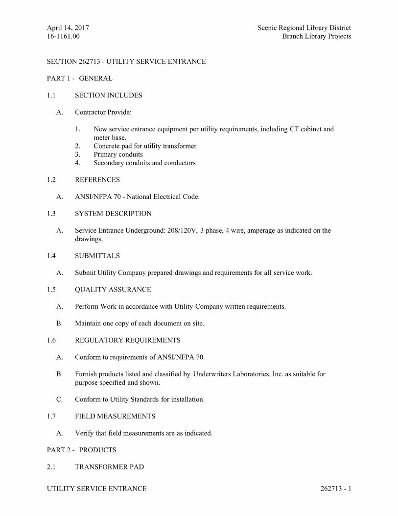
April 14, 2017 Scenic Regional Library District
16-1161.00 Branch Library Projects
UTILITY SERVICE ENTRANCE 262713 - 1
SECTION 262713 - UTILITY SERVICE ENTRANCE
PART 1 - GENERAL
1.1 SECTION INCLUDES
A. Contractor Provide:
1. New service entrance equipment per utility requirements, including CT cabinet and
meter base.
2. Concrete pad for utility transformer
3. Primary conduits
4. Secondary conduits and conductors
1.2 REFERENCES
A. ANSI/NFPA 70 - National Electrical Code.
1.3 SYSTEM DESCRIPTION
A. Service Entrance Underground: 208/120V, 3 phase, 4 wire, amperage as indicated on the
drawings.
1.4 SUBMITTALS
A. Submit Utility Company prepared drawings and requirements for all service work.
1.5 QUALITY ASSURANCE
A. Perform Work in accordance with Utility Company written requirements.
B. Maintain one copy of each document on site.
1.6 REGULATORY REQUIREMENTS
A. Conform to requirements of ANSI/NFPA 70.
B. Furnish products listed and classified by Underwriters Laboratories, Inc. as suitable for
purpose specified and shown.
C. Conform to Utility Standards for installation.
1.7 FIELD MEASUREMENTS
A. Verify that field measurements are as indicated.
PART 2 - PRODUCTS
2.1 TRANSFORMER PAD
April 14, 2017 Scenic Regional Library District
16-1161.00 Branch Library Projects
UTILITY SERVICE ENTRANCE 262713 - 2
A. As indicated on Utility standard for installation drawing.
B. Coordinate requirements for cable terminations with Utility.
2.2 CURRENT TRANSFORMER ENCLOSURE
A. As indicated on Utility standard for installation drawing.
2.3 METER ENCLOSURE
A. As indicated on Utility standard for installation drawing.
2.4 PRIMARY CONDUIT
A. As indicated on Utility standard for installation drawing.
B. All bends shall be galvanized rigid steel conduit, 36” minimum radius.
PART 3 - EXECUTION
3.1 EXAMINATION
A. Verify that service equipment is ready to be connected and energized.
3.2 PREPARATION
A. Make arrangements with Utility Company to obtain permanent electric service to the
Project. Arrange for all necessary inspections by Utility. The Electrical
Contractor is responsible to ensure that all Utility requirements are met.
3.3 INSTALLATION
A. Coordinate installation requirements with Utility prior to beginning work.
END OF SECTION 262713
April 14, 2017 Scenic Regional Library District
16-1161.00 Branch Library Projects
WIRING DEVICES 262726 - 1
SECTION 262726 - WIRING DEVICES
PART 1 - GENERAL
1.1 WORK INCLUDES
A. Contractor Provide:
1. Wall switches.
2. Receptacles.
3. Device plates and decorative box covers.
4. In-use coverplates.
1.2 REFERENCES
A. NECA - Standard of Installation.
B. NEMA WD 1 - General Requirements for Wiring Devices.
C. NEMA WD 6 - Wiring Device -- Dimensional Requirements.
D. NFPA 70 - National Electrical Code.
1.3 SUBMITTALS
A. Product Data: Provide manufacturers’ catalog information showing dimensions, colors, and
configurations.
B. Submit manufacturers’ installation instructions.
1.4 QUALIFICATIONS
A. Manufacturer: Company specializing in manufacturing the Products specified in this section
with minimum 3 years experience.
1.5 REGULATORY REQUIREMENTS
A. Conform to requirements of NFPA 70.
B. Provide Products listed and classified by Underwriters Laboratories, Inc., or other testing firm
acceptable to the authority having jurisdiction as suitable for the purpose specified and
indicated.
PART 2 - PRODUCTS
2.1 WALL SWITCHES
A. Manufacturers:
April 14, 2017 Scenic Regional Library District
16-1161.00 Branch Library Projects
WIRING DEVICES 262726 - 2
1. Hubbell: 1221 (SP), 1223 (3-way), 1224 (4-way)
2. Arrow Hart: 1991 (SP), 1993 (3-way), 1994 (4-way).
3. Leviton: 1221-2 (SP), 1223-2 (3-way), 1224-2 (4-way).
B. Description: NEMA WD 1, heavy-duty AC only general-use snap switch. Provide device
suitable for use with stranded wire.
C. Device Body: White plastic with toggle handle.
D. Voltage Rating: 120-277 volts, AC.
E. Current Rating: 20 amperes.
2.2 Low voltage switch shall be a 2 position momentary switch. Switch shall match other wall
switches on project.
2.3 RECEPTACLES
A. Duplex Convenience Receptacle:
1. Hubbell 5362W.
2. Arrow Hart 5362W.
3. Leviton 5362-W.
B. Description: NEMA WD 1; heavy-duty general-use receptacle. Provide device suitable for use
with stranded conductors.
C. Device Body: White plastic.
D. Convenience Receptacle: NEMA Type 5-20R.
E. GFCI Receptacle: Convenience receptacle with integral ground fault circuit interrupter to meet
regulatory requirements: Hubbell GF5362W, Arrow Hart VGW20W, Leviton 7899W.
2.4 WALL PLATES
A. Manufacturers:
1. Hubbell.
2. Arrow Hart.
3. Leviton.
B. Flush Mounted Plates: Nylon beveled type with smooth rolled outer edge,
white colored.
C. Weatherproof Cover Plate: Gasketed cast metal with hinged gasketed device
cover.
2.5 IN-USE COVERPLATE
April 14, 2017 Scenic Regional Library District
16-1161.00 Branch Library Projects
WIRING DEVICES 262726 - 3
A. NEMA 3R, hinged transparent polycarbonate cover with provisions for locking, listed as
weatherproof with cord attached to the receptacle, meeting NEC 2002, 406.8(b).
PART 3 - EXECUTION
3.1 EXAMINATION
A. Verify that outlet boxes are installed at proper height.
B. Verify that wall openings are neatly cut and will be completely covered by wall plates.
C. Verify that boxes are adjusted properly.
D. Verify that branch circuit wiring installation is completed, tested, and ready for connection to
wiring devices.
3.2 PREPARATION
A. Provide extension rings to bring outlet boxes flush with finished surface.
B. Clean debris from outlet boxes.
3.3 INSTALLATION
A. Install in accordance with NECA "Standard of Installation."
B. Install devices plumb and level.
C. Install switches with OFF position down.
D. Install receptacles with grounding pole on bottom.
E. Connect wiring device grounding terminal to branch circuit equipment grounding conductor per NEC.
F. Install decorative plates on switch, receptacle, and blank outlets in finished areas.
G. Connect wiring devices by wrapping conductor around screw terminal. Specification or
hospital grade heavy duty screw clamps may be used. Do not wire through devices.
H. Use jumbo size plates for outlets installed in masonry walls.
I. Install galvanized steel plates on outlet boxes and junction boxes in unfinished areas, above
accessible ceilings, and on surface mounted outlets.
3.4 COORDINATION
A. Coordinate locations of outlet boxes provided under Section 260533 to obtain mounting heights
specified and indicated on drawings.
April 14, 2017 Scenic Regional Library District
16-1161.00 Branch Library Projects
WIRING DEVICES 262726 - 4
B. Install wall switch or dimmer at 48 inches above finished floor.
C. Install convenience receptacle 18 inches above finished floor unless indicated otherwise.
D. Install convenience receptacle 6 inches above counter or backsplash of counter.
3.5 FIELD QUALITY CONTROL
A. Inspect each wiring device for defects.
B. Operate each wall switch with circuit energized and verify proper operation.
C. Verify that each receptacle device is energized.
D. Test each receptacle device for proper polarity.
E. Test each GFCI receptacle device for proper operation.
3.6 ADJUSTING
A. Adjust devices and wall plates to be flush and level.
3.7 CLEANING
A. Clean exposed surfaces to remove splatters and restore finish.
END OF SECTION 262726
April 14, 2017 Scenic Regional Library District
16-1161.00 Branch Library Projects
ENCLOSED SWITCHES 262816 - 1
SECTION 262816 – ENCLOSED SWITCHES
PART 1 - GENERAL
1.1 SECTION INCLUDES
A. Contractor Provide:
1. Fusible switches.
2. Non-fusible switches.
3. Fuses.
1.2 REFERENCES
A. NEMA KS 1 - Enclosed Switches.
B. NFPA 70 - National Electrical Code
C. UL 198C - High-Interrupting Capacity Fuses; Current Limiting Type.
D. UL 198E - Class R Fuses.
E. UL 198 - Class J Fuses.
1.3 SUBMITTALS
A. Submit Product Data: Provide switch ratings and enclosure dimensions.
B. Submit Manufacturer's Instructions: Indicate application conditions and limitations of use
stipulated by Product testing agency specified under Regulatory Requirements. Include
instructions for storage, handling, protection, examination, preparation, installation, and
starting of Product.
1.4 QUALIFICATIONS
A. Manufacturer: Company specializing in manufacturing Products specified in this Section with
minimum three years documented experience.
1.5 REGULATORY REQUIREMENTS
A. Conform to requirements of NFPA 70.
B. Furnish products listed and classified by a Nationally Recognized Testing Laboratory (NRTL)
as suitable for purpose specified and shown.
PART 2 - PRODUCTS
2.1 MANUFACTURERS
April 14, 2017 Scenic Regional Library District
16-1161.00 Branch Library Projects
ENCLOSED SWITCHES 262816 - 2
A. General Electric.
B. Square-D.
C. Siemens.
D. Cutler Hammer
2.2 ENCLOSED SWITCHES
A. Fusible Switch Assemblies: NEMA KS 1, Type HD load interrupter enclosed knife switch with externally operable handle interlocked to prevent opening front cover with switch in ON position. Handle lockable in OFF position. Fuse clips: Designed to accommodate Class R fuses, Class L and Class J in main switchboards. Provide an equipment grounding kit.
B. Non-fusible Switch Assemblies: NEMA KS 1, Type HD load interrupter enclosed knife switch with externally operable handle interlocked to prevent opening front cover with switch in ON position. Handle lockable in OFF position. Provide an equipment grounding kit.
C. Enclosures: NEMA KS 1.
1. Interior Dry Locations: Type 1.2. Exterior Locations: Type 3R.
2.3 FUSES
A. Manufacturers:
1. Bussman.2. Gould/Shawmut.3. Littlefuse.
B. Description: Dual element, current limiting, one-time fuse, 250 or 600 volt, UL 198E, Class RK 1, Class J and Class L.
C. Interrupting Rating: 200,000 RMS amperes.
D. Provide three (3) spare fuses of each fuse type and size.
PART 3 - EXECUTION
3.1 INSTALLATION
A. Install disconnect switches where indicated.
B. Install fuses in fusible disconnect switches.
C. Provide adhesive label on inside door of each switch indicating UL fuse class and size for replacement.
D. Provide label on front of all enclosures as specified in 260553.
END OF SECTION 262816
April 14, 2017 Scenic Regional Library District
16-1161.00 Branch Library Projects
LUMINAIRES 26 5100 - 1
SECTION 265100 - LUMINAIRES
PART 1 - GENERAL
1.1 SUMMARY
A. Section Includes:
1. Interior luminaires and accessories.
2. Exterior luminaires, poles, and accessories.
3. Lamps and ballasts.
4. Emergency lighting units and exit signs.
5. Luminaire supports.
B. Related Sections:
1. Section 262726 "Lighting Control Devices" for automatic control of lighting, including
time switches, photoelectric relays, occupancy sensors, digitally addressable lighting
control systems, and multi-pole lighting relays and contactors.
1.2 DEFINITIONS
A. CCT: Correlated color temperature.
B. CRI: Color-rendering index.
C. LED: Light Emitting Diode
D. LER: Luminaire efficacy rating.
E. Lumen: Measured output of lamp and luminaire, or both.
F. Luminaire: Complete lighting fixture, including ballast housing if provided.
G. Pole: Luminaire support structure, including tower used for large area illumination.
1.3 SUBMITTALS
A. For each type of luminaire, arranged in order of luminaire designation. Include complete product
model number and product data sheets on features, accessories, finishes, and the following:
1. Physical description of luminaire including dimensions, as well as effective projected area
for exterior luminaires.
2. Details of attaching luminaires and accessories.
3. Emergency lighting units including battery and charger.
4. Life, output (lumens, CCT, and CRI), and energy-efficiency data for lamps.
5. LED photometric report per latest IESNA LM-79-08 testing guidelines, including
luminaire model number, manufacturer of LED chip array/board and driver, input wattage,
and independent testing laboratory name, report number, and date tested.
April 14, 2017 Scenic Regional Library District
16-1161.00 Branch Library Projects
LUMINAIRES 26 5100 - 2
6. Dimmer device data for all LED luminaires specified as dimming. Must be from approved
manufacturer per luminaire manufacturer requirements, furnished and installed by
contractor. Contractor responsible for dimmer control and luminaire compatibility.
7. Pole information including: Materials, dimensions, finishes, means of attaching luminaire
to support, anchor bolts and templates, structural analysis and manufactured pole
foundations.
B. Custom Luminaires: Include plans, elevations, sections, details, and attachments to other work.
1. Detail equipment assemblies and indicate dimensions, weights, loads, required clearances,
method of field assembly, components, and location and size of each field connection.
2. Wiring Diagrams: For power, signal, and control wiring.
1.4 QUALITY ASSURANCE
A. Luminaire Photometric Data Testing Laboratory Qualifications: Provided by manufacturers'
laboratories that are accredited under the National Volunteer Laboratory Accreditation Program
for Energy Efficient Lighting Products, or by an independent agency complying with the IESNA
Lighting Measurements Testing & Calculation Guides.
B. Comply with IEEE C2, “National Electrical Safety Code” and NFPA 70.
1.5 COORDINATION
A. Coordinate layout and installation of luminaires and suspension system with other construction
that penetrates ceilings or is supported by them, including HVAC equipment, fire-suppression
system, and partition assemblies.
1.6 DELIVERY, STORAGE, AND HANDLING
A. Deliver luminaire and components to site. Store such that luminaires, finishes, lenses, and trims
are protected. Install with protective films on and remove only after construction clean-up is
complete.
B. Store poles on decay-resistant-treated skids at least 12 inches above grade and vegetation. Support
poles to prevent distortion and arrange to provide free air circulation. Prevent breakage and
damage to finish.
1.7 WARRANTY
A. Warranty Period for LED chips/arrays and drivers: 5 years from date of substantial completion.
B. Warranty Period for Emergency Lighting Unit Batteries: 5 years from date of substation
completion.
C. Warranty Period for Luminaires: 5 years LED fixtures and 2 years for others from date of
substantial completion.
D. Warranty Period for Poles: 3 years from date of substantial completion.
April 14, 2017 Scenic Regional Library District
16-1161.00 Branch Library Projects
LUMINAIRES 26 5100 - 3
PART 2 - PRODUCTS
2.1 MANUFACTURERS
A. Products: Refer to Luminaire Schedule on the drawings.
2.2 GENERAL REQUIREMENTS FOR LUMINAIRES AND COMPONENTS
A. All luminaires shall carry a UL listing, unless otherwise noted on the Luminaire Schedule.
Exterior luminaires shall carry a UL wet location listing as well as designated IP rating, unless
otherwise noted on the Luminaire Schedule.
B. Recessed Luminaires: Housing shall be constructed of aluminum (UON), free of burrs and sharp
corners and edges, free of light leakage and accessible without use of tools. Components shall be
formed and supported to prevent warping and sagging. Lamp and ballast compartments shall be
accessible from below the ceiling.
1. Where fire-rated ceilings are specified, luminaires should be provided with listed
enclosures meeting requirements to maintain fire-rated system rating.
C. Suspended Luminaires: Canopies, power feeds, and mounting accessories shall be coordinated
with architectural-designated ceiling type. Luminaires shall be installed plumb and level at
luminaire height designated on Luminaire Schedule.
D. Exterior Luminaires: Housings shall be rigidly formed, weather- and light-tight enclosures that
will not warp, sag, or deform in use. Doors shall be removable for cleaning or replacing lenses,
designed to disconnect ballast when door opens.
1. Diffusers and Globes: Acrylic Lighting Diffusers shall be 100 percent virgin acrylic
plastic, minimum 0.125 inch thickness. High resistance to yellowing and other changes due
to aging, exposure to heat, and UV radiation. Glass globes shall be annealed crystal glass
unless otherwise indicated.
2. In-grade luminaires shall have separate compartments for wire entry and lamp chamber,
separation shall prevent surface temperature of exceeding 115°F.
2.3 LIGHT EMITTING DIODE (LED) LUMINAIRE SYSTEMS
A. Light emitting diodes shall have a minimum color rendering index (CRI) of 80 for interior
applications and 70 for exterior applications. Refer to Luminaire Schedule for color temperature
of the luminaires.
B. Color changing LED chip arrays shall have chip colors as noted on the Luminaire Schedule.
C. LED chips shall be wired so that operation of chip array is not prohibited by failure of one chip.
D. LED Driver:
1. Solid state driver with integral heat sink. Driver shall have overheat, short-circuit and
overload protection, power factor 0.90 or above and maximum total harmonic distortion of
20%. Surge suppression device for all exterior luminaires minimum 9kV.
April 14, 2017 Scenic Regional Library District
16-1161.00 Branch Library Projects
LUMINAIRES 26 5100 - 4
2. Drivers shall have dimming capabilities as outlined in the luminaire schedule for each
luminaire type.
3. Driver shall have a minimum of 50,000 hours rated life.
2.4 LUMINAIRE SUPPORT COMPONENTS
A. Comply with Section 26 0529 "Hangers and Supports" for channel- and angle-iron supports and
nonmetallic channel and angle supports.
B. Single-Stem Hangers: 1/2-inch steel tubing with swivel ball fittings and ceiling canopy. Finish
same as luminaire.
C. Twin-Stem Hangers: Two, 1/2-inch steel tubes with single canopy designed to mount a single
luminaire. Finish same as luminaire.
D. Wires: ASTM A 641/A 641M, Class 3, soft temper, zinc-coated steel, 12 gage.
E. Wires for Humid Spaces: ASTM A 580/A 580M, Composition 302 or 304, annealed stainless
steel, 12 gage.
F. Rod Hangers: 3/16-inch minimum diameter, cadmium-plated, threaded steel rod.
G. Hook Hangers: Integrated assembly matched to luminaire and line voltage and equipped with
threaded attachment, cord, and locking-type plug.
2.5 ACCEPTABLE MANUFACTURERS – POLES
A. Manufacturer of Luminaire.
B. Valmont Poles.
C. Shakespeare Composite Structures.
D. United Lighting Standards Inc.
E. Gardco Poles.
F. Ameron Poles.
2.6 LIGHTING POLES
A. Poles: Refer to lighting schedule.
B. Structural Characteristics: Comply with AASHTO LTS-4-M.
1. Wind-Load Strength of Poles: Adequate at indicated heights above grade without failure,
permanent deflection, or whipping in steady winds of speed 100mph with a gust factor of
1.3 with luminaires, brackets, and banners mounted.
C. Handhole: 2 inches x 4 inches with weatherproof cover secured by stainless-steel captive screws.
Provide gasket with matching finish.
April 14, 2017 Scenic Regional Library District
16-1161.00 Branch Library Projects
LUMINAIRES 26 5100 - 5
D. Pole-Top Tenons: Fabricated to support luminaire or luminaires and brackets indicated, and
securely fastened to pole top.
E. Grounding and Bonding Lugs: Welded 1/2-inch threaded lug, complying with requirements in
Section 26 0526 "Grounding and Bonding," listed for attaching grounding and bonding
conductors of type and size listed in that Section, and accessible through handhole.
F. Duplex Receptacle: 120 V, 20 A in a weatherproof assembly complying with Section 26 2726
"Wiring Devices" for ground-fault circuit-interrupter type.
1. Nonmetallic polycarbonate plastic or reinforced fiberglass, weatherproof in use, cover, <
that when mounted results in NEMA 250, Type 4x enclosure with cord opening.
2. With lockable hasp and latch that complies with OSHA lockout and tag-out requirements.
G. Anchor Bolts: As recommended by pole manufacturer, installed per manufacturer’s template
with washers and hex nuts. Grout between anchor plate and concrete base with non-shrink grout
after pole is plumbed.
H. Vibration Damper: As recommended by pole manufacturer, internal to pole. Provide additional
pole top damper for first mode vibration on single-head poles where recommended by
manufacturer.
I. Concrete as indicated on plans, provide reinforcing as indicated on plans. Poles exposed to
concrete bases taller than 6” AFG, contractor shall provide a rubbed finish on the exposed
surfaces. Apply a water proof agent after concrete has cured and after rubbed finish.
PART 3 - EXECUTION
3.1 INSTALLATION
A. Luminaires:
1. Set level, plumb, and square with ceilings and walls unless otherwise indicated.
2. Install lamps in each luminaire.
B. Temporary Lighting: If it is necessary, and approved by Architect, to use permanent luminaires
for temporary lighting, install and energize the minimum number of luminaires necessary. When
construction is sufficiently complete, remove the temporary luminaires, disassemble, clean
thoroughly, install new lamps, and reinstall.
C. Remote Mounting of Ballasts: Distance between the ballast and luminaire shall not exceed that
recommended by ballast manufacturer. Verify, with ballast manufacturers, maximum distance
between ballast and luminaire.
D. Lay-in Ceiling Luminaire Supports: Use grid as a support element.
1. Install ceiling support system rods or wires, independent of the ceiling suspension devices,
for each luminaire. Locate not more than 6 inches from luminaire corners.
2. Support Clips: Fasten to luminaires and to ceiling grid members at or near each luminaire
corner with clips that are UL listed for the application.
April 14, 2017 Scenic Regional Library District
16-1161.00 Branch Library Projects
LUMINAIRES 26 5100 - 6
3. Luminaires of Sizes Less Than Ceiling Grid: Install as indicated on reflected ceiling plans
or center in acoustical panel, and support luminaires independently with at least two 3/4-
inch metal channels spanning and secured to ceiling tees.
4. Install at least one independent support rod or wire from structure to a tab on luminaire.
Wire or rod shall have breaking strength of the weight of luminaire at a safety factor of 3.
E. Suspended Luminaire Support:
1. Pendants and Rods: Where longer than 48 inches, brace to limit swinging.
2. Stem-Mounted, Single-Unit Luminaires: Suspend with twin-stem hangers.
3. Continuous Rows: Use tubing or stem for wiring at one point and tubing or rod for
suspension for each unit length of luminaire chassis, including one at each end.
4. Do not use grid as support for pendant luminaires. Connect support wires or rods to
building structure.
F. When installing luminaires, the contractor shall use the luminaire manufacturer’s mounting
hardware and follow all manufacturer’s installation direction.
G. All recessed downlights must be installed so that the bottom of the throat is even with the finished
ceiling plane. The overlapping flange must then fit flush to the ceiling plane/throat. No light leak
must be visible. All miscellaneous hardware above the ceiling plane to accomplish the above
shall be included in the base bid.
H. All recessed downlights shall have self-flanged reflectors unless otherwise noted.
I. When installing compact fluorescent lamp luminaires, consistent lamp orientation shall be
maintained in a given area.
J. When luminaires are installed in continuous rows of 2 or more, luminaires shall be approved for
use as wireway.
K. Alignment: Align pole foundations and poles for optimum directional alignment of luminaires
and their mounting provisions on the pole.
L. Embedded Poles: Set poles to depth below finished grade indicated on Drawings, but not less
than one-sixth of pole height, installed plumb with double nuts for adjustment. Grout around pole
anchor base.
M. Raise and set poles using web fabric slings (not chain or cable), or non-chafing ropes.
N. Bollards and Ground-Mount Luminaires: Align units for optimum directional alignment of light
distribution. Install on concrete base with top 4 inches above finished grade or surface at bollard
location. Cast conduit into base, shape base to match shape of bollard base. Finish by troweling
and rubbing smooth.
O. Bond luminaires and metal accessories to branch circuit equipment grounding conductor.
P. Ground metal and non-metallic poles and support structures according to Section 26 0526
“Grounding and Bonding.”
April 14, 2017 Scenic Regional Library District
16-1161.00 Branch Library Projects
LUMINAIRES 26 5100 - 7
3.2 IDENTIFICATION
A. Install labels with panel and circuit numbers on concealed junction and outlet boxes. Comply
with requirements for identification specified in Section 26 0553 "Identification for Electrical
Systems."
3.3 FIELD QUALITY CONTROL
A. Test for Emergency Lighting: Interrupt power supply to demonstrate proper operation. Verify
transfer from normal power to battery and retransfer to normal.
B. Verify that self-luminous exit signs are installed according to their listing and the requirements
in NFPA 101.
C. Illumination Observations: Verify normal operation of luminaires after installing luminaires
and energizing circuits with normal power source.
D. Prepare a written report of tests, inspections, observations, and verifications indicating and
interpreting results. If adjustments are made to lighting system, retest to demonstrate compliance
with standards.
3.4 STARTUP SERVICE
A. Burn-in all lamps that require specific aging period to operate properly, prior to occupancy by
Owner. Burn-in fluorescent and compact fluorescent lamps intended to be dimmed, for at least
100 hours at full voltage.
3.5 ADJUSTING AND CLEANING
A. Aim and adjust luminaires to provide illumination levels and distribution as directed. This work
will be completed at night after hours. Contractor shall provide all labor to aim fixtures as directed
by the architect/engineer.
B. Align luminaires and clean lenses and diffusers at completion of work. Clean paint splatters, dirt,
and debris from installed luminaires. Touch up luminaire and pole finishes as necessary.
C. Inspect each installed luminaire for damage. Replace damaged luminaires and components.
END OF SECTION 265100
April 14, 2017 Scenic Regional Library District
16-1161.00 Branch Library Projects
SITE LIGHTING 265629 - 1
SECTION 265629 - SITE LIGHTING
PART 1 - GENERAL
1.1 WORK INCLUDES
A. Contractor Provide:
1. Exterior luminaries and accessories.
1.2 REFERENCES
A. ANSI/NFPA 70 - National Electrical Code.
1.3 PROJECT RECORD DOCUMENTS
A. Accurately record actual locations of each luminaire and circuit routing to each
luminaire.
1.4 QUALIFICATIONS
A. Manufacturer: Company specializing in manufacturing products specified in this
Section with minimum three years documented experience.
1.5 REGULATORY REQUIREMENTS
A. Conform to requirements of ANSI/NFPA 70.
B. Furnish products listed and classified by Underwriters Laboratories, Inc. or other
testing firm acceptable to authority having jurisdiction as suitable for purpose specified
and shown.
1.6 DELIVERY, STORAGE, AND HANDLING
A. Accept products on site. Inspect for damage.
1.7 WARRANTIES
A. Provide 5 year warranty on all LED fixtures.
PART 2 - PRODUCTS
2.1 LUMINAIRES
A. Furnish products as specified on Drawings.
B. Substitutions: none

April 14, 2017 Scenic Regional Library District
16-1161.00 Branch Library Projects
SITE LIGHTING 265629 - 2
April 14, 2017 Scenic Regional Library District
16-1161.00 Branch Library Projects
SITE LIGHTING 265629 - 3
2.2 LAMPS
A. Provide lamp type specified for luminaire.
B. LED Lamps
1. Per fixture Led color temperature binning +/- 275K from specified fixture color
temperature.
2. Minimum 70CRI.
3. Leds meet or exceed LM79 standard.
C. Luminaire to be IP66 rated.
D. Alternate lamp wattages to those specified on the drawings will not be considered.
2.3 FOUNDATIONS AND BASES
A. Concrete, as indicated on plans, provide reinforcing as indicated on plans.
B. For poles with exposed concrete bases taller than 6” AFG, contractor shall provide a
rubbed finish on the exposed surfaces.
1. Apply a water proof agent after concrete has cured and been rubbed.
C. Bases and poles shall conform to AASHTO standards.
2.4 LED DRIVERS
A. LED driver
1. UL listed.
2. Minimum .9 power factor.
3. Less than 20% THD.
4. Minimum 9kV surge suppression protection.
5. Substitutions: none.
6. Voltage: Match luminaire voltage.
B. Provide a disconnecting means for each circuit at the pole.
PART 3 - EXECUTION
3.1 EXAMINATION
A. Examine each luminaire to determine suitability for lamps specified.
3.2 INSTALLATION
A. Install in accordance with manufacturers' instructions.
B. Install lamps in each luminaire.
April 14, 2017 Scenic Regional Library District
16-1161.00 Branch Library Projects
SITE LIGHTING 265629 - 4
C. Bond luminaires and metal accessories to branch circuit equipment grounding
conductor.
3.3 FIELD QUALITY CONTROL
A. Operate each luminaire after installation and connection. Inspect for improper
connections and operation.
3.4 ADJUSTING
A. Aim and adjust luminaires to provide illumination levels and distribution as directed.
This work will be completed at night after hours. Contractor shall provide all labor to
aim fixtures as directed by the architect/engineer.
B. Relamp luminaires which have failed lamps at Date of Substantial Completion.
3.5 CLEANING
A. Clean electrical parts to remove conductive and deleterious materials.
B. Remove dirt and debris from enclosure.
C. Clean photometric control surfaces as recommended by manufacturer.
D. Clean finishes and touch up damage.
END OF SECTION 265629
April 14, 2017 Scenic Regional Library District
16-1161.00 Branch Library Projects
COMMUNICATIONS CABLING SYSTEM 271000 - 1
SECTION 271000 - STRUCTURED CABLING
PART 1 - GENERAL
1.1 WORK INCLUDES
A. Contractor shall provide:
1. Category 6 cabling.
2. Category 6 patch panels.
3. Category 6 patch cords.
4. Category 6A cabling.
5. Category 6A patch panels.
6. Multipair copper trunk cable.
7. Fiber optic cabling.
8. Fiber optic termination cabinet with adapter panels.
9. Fiber optic patch cords.
10. 110IDC Termination Blocks for Analog and Telephone (Voice) cabling.
11. Building Entrance Terminal (with electronic modules).
12. Water-resistant ("weatherproof") coverplate.
13. Identification and Labeling for Wireless Access Points.
14. Connectors and Terminations.
15. Floor-mounted Open Frame Reay Rack.
16. Wall-mounted Open Frame Relay Rack.
17. Testing and labeling of all cabling.
18. 20-year minimum Cabling System Warranty.
1.2 RELATED SECTIONS
A. Section 260533 – Conduit.
B. Section 260534 – Boxes.
C. Section 262726 – Wiring Devices.
D. Section 260553 – Electrical Identification.
E. Section 271000 – Communication Raceway System.
1.3 RELATED DOCUMENTS
A. Drawings and general provisions of the Contract, including General and Supplementary Conditions
April 14, 2017 Scenic Regional Library District
16-1161.00 Branch Library Projects
COMMUNICATIONS CABLING SYSTEM 271000 - 2
apply to this Section.
B. Design Criteria: The structured wiring system shall be comprised of horizontal copper and backbone
fiber optic cables routed throughout the building. This system shall provide transmission media
for voice and data signals. The contractor shall provide structured wiring transmission media,
components, and testing as specified herein at locations shown on the plans and in conformance
with manufacturers’ recommendations.
1.4 SUMMARY
A. This Section includes the following types of control and signal transmission media:
1. UTP Copper, 4-Pair CAT 6.
2. STP/FTP Copper, 4-Pait CAT-6A.
3. Multipair CAT-5e.
4. Singlemode fiber optic cabling (OS2).
5. Multimode fiber optic cabling, 50um (OM3).
6. Multimode fiber optic cabling, 62.5um (OM1).
B. This Section includes the patch panels, connectors, patch cords, outlets, terminal blocks, etc. as
required to provide a complete structured system. Documentation is critical to the successful
installation of the structured wiring system. Unless agreed to in writing the systems shall be
documented as specified herein or shown on the drawings.
C. Installation shall conform to the 2011 edition of NFPA 70 (National Electric Code, NEC),
Telecommunications Industry Association and Electronic Industry Alliance (TIA/EIA), Building
Industry Consulting Services International (BICSI), Telecommunications Distribution Methods
Manual (TDMM), and local codes and ordinances, as applicable.
D. In addition, Installation shall conform to the latest edition of the following Codes and Standards:
1. ANSI/TIA 568-C.1 Commercial Building Telecommunications Cabling Standard.
2. ANSI/TIA 568-C.2, Balanced Twisted-Pair Cabling and Components.
3. ANSI/TIA 569-C, Commercial Building Standards For Telecommunications Pathways And
Spaces
4. ANSI/TIA 606-B The Administration Standard For The Telecommunications Infrastructure
Of Commercial Building
5. ANSI/TIA 607-B, Commercial Building Grounding And Bonding Requirements.
6. ANSI/TIA 862-A, Building Automation Systems Cabling Standard.
7. ASTM D 4566-05, Standard Test Methods for Electrical Performance Properties of
Insulations and Jackets for Telecommunications Wire and Cable, 2005
8. BICSI Telecommunications Distribution Methods Manual (TDMM) 13th Edition
9. BICSI Information Transport Installation Manual (ITSM)
10. ISO/IEC 11801 – Information Technology – Generic Cabling for Customer Premise
11. IEEE 802.3 Standard for Information technology -Telecommunications and information
exchange between systems - Local and metropolitan area networks – Specific requirements
Part 3: Carrier Sense Multiple Access with Collision Detection (CSMA/CD) Access Method
and Physical Layer Specifications
12. IEC 61156-1, Multicore and Symmetrical Pair/Quad Cables for Digital Communications –
Part 1: Generic Specification, 2005
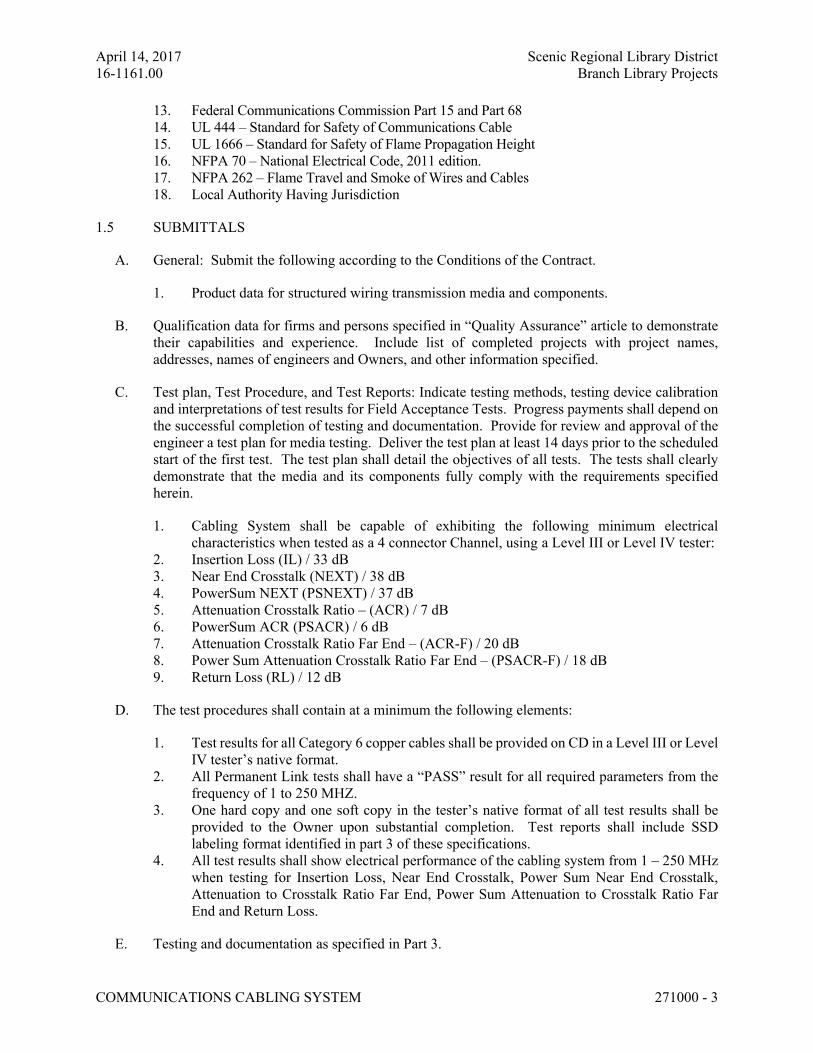
April 14, 2017 Scenic Regional Library District
16-1161.00 Branch Library Projects
COMMUNICATIONS CABLING SYSTEM 271000 - 3
13. Federal Communications Commission Part 15 and Part 68
14. UL 444 – Standard for Safety of Communications Cable
15. UL 1666 – Standard for Safety of Flame Propagation Height
16. NFPA 70 – National Electrical Code, 2011 edition.
17. NFPA 262 – Flame Travel and Smoke of Wires and Cables
18. Local Authority Having Jurisdiction
1.5 SUBMITTALS
A. General: Submit the following according to the Conditions of the Contract.
1. Product data for structured wiring transmission media and components.
B. Qualification data for firms and persons specified in “Quality Assurance” article to demonstrate
their capabilities and experience. Include list of completed projects with project names,
addresses, names of engineers and Owners, and other information specified.
C. Test plan, Test Procedure, and Test Reports: Indicate testing methods, testing device calibration
and interpretations of test results for Field Acceptance Tests. Progress payments shall depend on
the successful completion of testing and documentation. Provide for review and approval of the
engineer a test plan for media testing. Deliver the test plan at least 14 days prior to the scheduled
start of the first test. The test plan shall detail the objectives of all tests. The tests shall clearly
demonstrate that the media and its components fully comply with the requirements specified
herein.
1. Cabling System shall be capable of exhibiting the following minimum electrical
characteristics when tested as a 4 connector Channel, using a Level III or Level IV tester:
2. Insertion Loss (IL) / 33 dB
3. Near End Crosstalk (NEXT) / 38 dB
4. PowerSum NEXT (PSNEXT) / 37 dB
5. Attenuation Crosstalk Ratio – (ACR) / 7 dB
6. PowerSum ACR (PSACR) / 6 dB
7. Attenuation Crosstalk Ratio Far End – (ACR-F) / 20 dB
8. Power Sum Attenuation Crosstalk Ratio Far End – (PSACR-F) / 18 dB
9. Return Loss (RL) / 12 dB
D. The test procedures shall contain at a minimum the following elements:
1. Test results for all Category 6 copper cables shall be provided on CD in a Level III or Level
IV tester’s native format.
2. All Permanent Link tests shall have a “PASS” result for all required parameters from the
frequency of 1 to 250 MHZ.
3. One hard copy and one soft copy in the tester’s native format of all test results shall be
provided to the Owner upon substantial completion. Test reports shall include SSD
labeling format identified in part 3 of these specifications.
4. All test results shall show electrical performance of the cabling system from 1 – 250 MHz
when testing for Insertion Loss, Near End Crosstalk, Power Sum Near End Crosstalk,
Attenuation to Crosstalk Ratio Far End, Power Sum Attenuation to Crosstalk Ratio Far
End and Return Loss.
E. Testing and documentation as specified in Part 3.
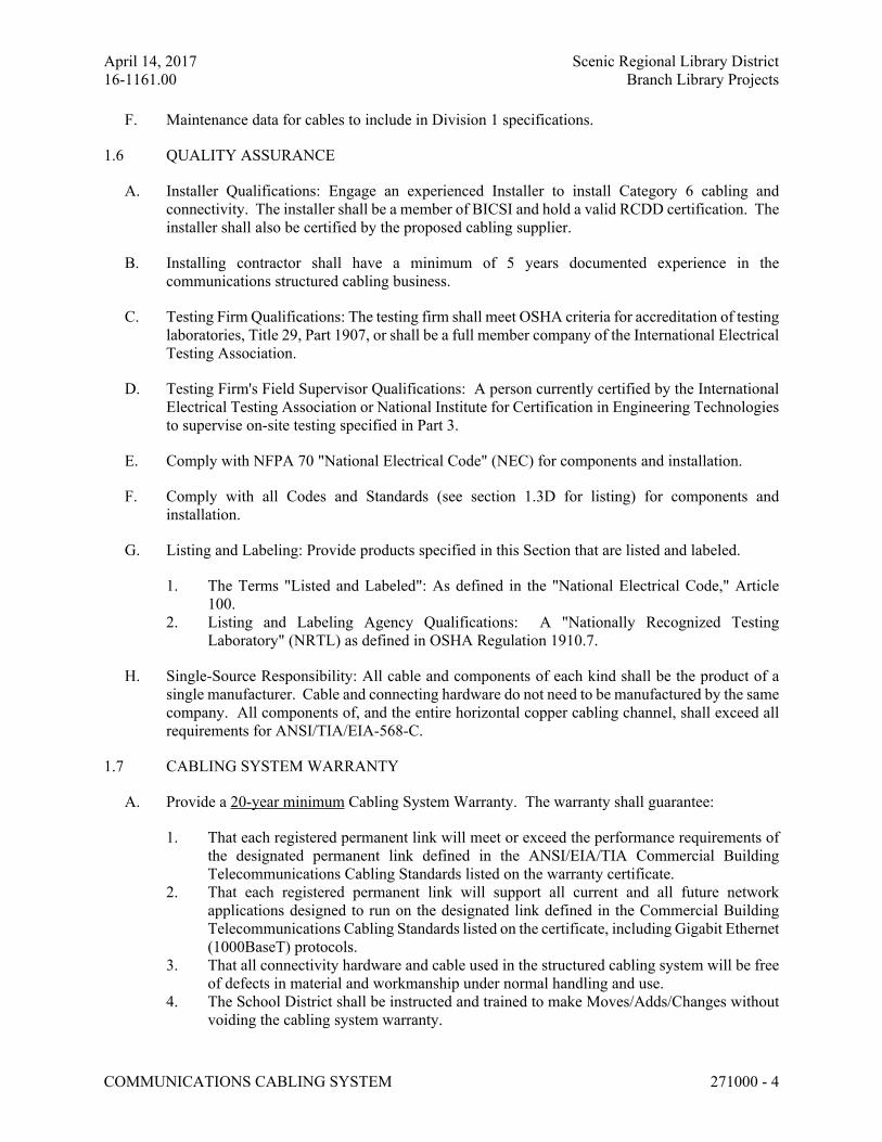
April 14, 2017 Scenic Regional Library District
16-1161.00 Branch Library Projects
COMMUNICATIONS CABLING SYSTEM 271000 - 4
F. Maintenance data for cables to include in Division 1 specifications.
1.6 QUALITY ASSURANCE
A. Installer Qualifications: Engage an experienced Installer to install Category 6 cabling and
connectivity. The installer shall be a member of BICSI and hold a valid RCDD certification. The
installer shall also be certified by the proposed cabling supplier.
B. Installing contractor shall have a minimum of 5 years documented experience in the
communications structured cabling business.
C. Testing Firm Qualifications: The testing firm shall meet OSHA criteria for accreditation of testing
laboratories, Title 29, Part 1907, or shall be a full member company of the International Electrical
Testing Association.
D. Testing Firm's Field Supervisor Qualifications: A person currently certified by the International
Electrical Testing Association or National Institute for Certification in Engineering Technologies
to supervise on-site testing specified in Part 3.
E. Comply with NFPA 70 "National Electrical Code" (NEC) for components and installation.
F. Comply with all Codes and Standards (see section 1.3D for listing) for components and
installation.
G. Listing and Labeling: Provide products specified in this Section that are listed and labeled.
1. The Terms "Listed and Labeled": As defined in the "National Electrical Code," Article
100.
2. Listing and Labeling Agency Qualifications: A "Nationally Recognized Testing
Laboratory" (NRTL) as defined in OSHA Regulation 1910.7.
H. Single-Source Responsibility: All cable and components of each kind shall be the product of a
single manufacturer. Cable and connecting hardware do not need to be manufactured by the same
company. All components of, and the entire horizontal copper cabling channel, shall exceed all
requirements for ANSI/TIA/EIA-568-C.
1.7 CABLING SYSTEM WARRANTY
A. Provide a 20-year minimum Cabling System Warranty. The warranty shall guarantee:
1. That each registered permanent link will meet or exceed the performance requirements of
the designated permanent link defined in the ANSI/EIA/TIA Commercial Building
Telecommunications Cabling Standards listed on the warranty certificate.
2. That each registered permanent link will support all current and all future network
applications designed to run on the designated link defined in the Commercial Building
Telecommunications Cabling Standards listed on the certificate, including Gigabit Ethernet
(1000BaseT) protocols.
3. That all connectivity hardware and cable used in the structured cabling system will be free
of defects in material and workmanship under normal handling and use.
4. The School District shall be instructed and trained to make Moves/Adds/Changes without
voiding the cabling system warranty.
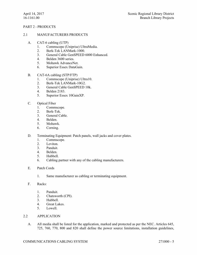
April 14, 2017 Scenic Regional Library District
16-1161.00 Branch Library Projects
COMMUNICATIONS CABLING SYSTEM 271000 - 5
PART 2 - PRODUCTS
2.1 MANUFACTURERS PRODUCTS
A. CAT-6 cabling (UTP)
1. Commscope (Uniprise) UltraMedia.
2. Berk-Tek LANMark-1000.
3. General Cable GenSPEED 6000 Enhanced.
4. Belden 3600 series.
5. Mohawk AdvanceNet.
6. Superior Essex DataGain.
B. CAT-6A cabling (STP/FTP)
1. Commscope (Uniprise) Ultra10.
2. Berk-Tek LANMark-10G2.
3. General Cable GenSPEED 10k.
4. Belden 2183.
5. Superior Essex 10GainXP.
C. Optical Fiber
1. Commscope.
2. Berk-Tek.
3. General Cable.
4. Belden.
5. Mohawk.
6. Corning.
D. Terminating Equipment: Patch panels, wall jacks and cover plates.
1. Commscope.
2. Leviton.
3. Panduit.
4. Belden.
5. Hubbell.
6. Cabling partner with any of the cabling manufacturers.
E. Patch Cords
1. Same manufacturer as cabling or terminating equipment.
F. Racks:
1. Panduit.
2. Chatsworth (CPI).
3. Hubbell.
4. Great Lakes.
5. Lowell.
2.2 APPLICATION
A. All media shall be listed for the application, marked and protected as per the NEC. Articles 645,
725, 760, 770, 800 and 820 shall define the power source limitations, installation guidelines,
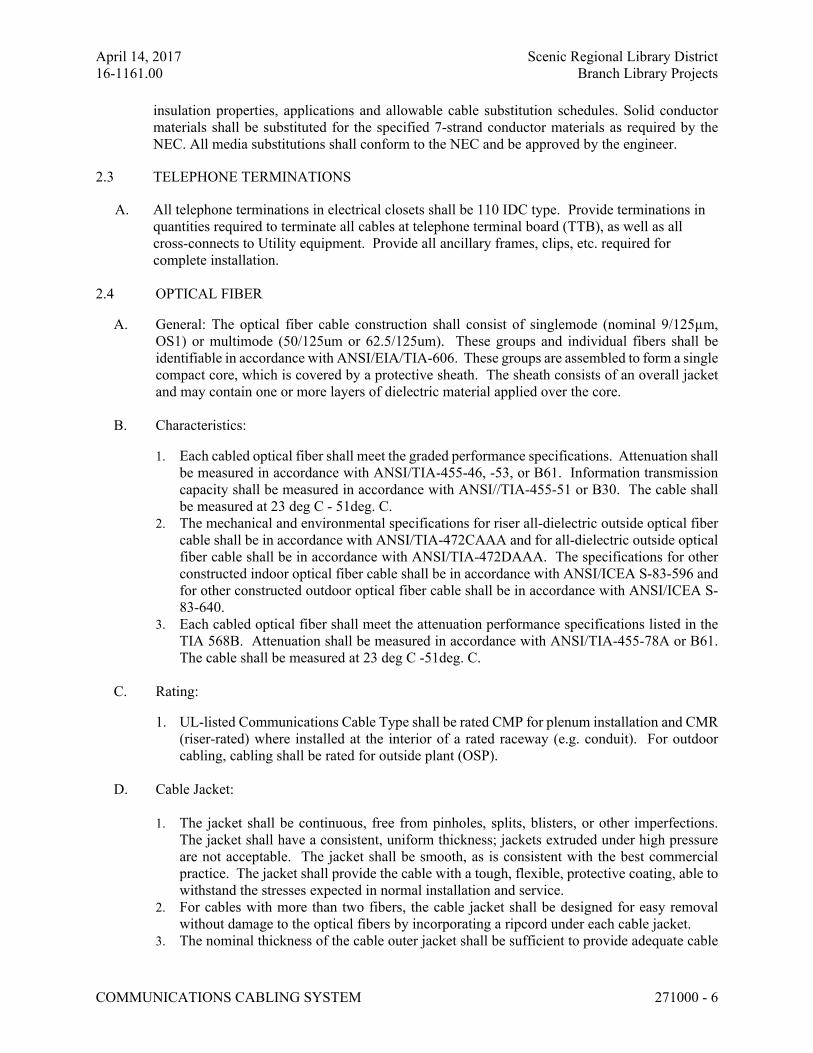
April 14, 2017 Scenic Regional Library District
16-1161.00 Branch Library Projects
COMMUNICATIONS CABLING SYSTEM 271000 - 6
insulation properties, applications and allowable cable substitution schedules. Solid conductor
materials shall be substituted for the specified 7-strand conductor materials as required by the
NEC. All media substitutions shall conform to the NEC and be approved by the engineer.
2.3 TELEPHONE TERMINATIONS
A. All telephone terminations in electrical closets shall be 110 IDC type. Provide terminations in
quantities required to terminate all cables at telephone terminal board (TTB), as well as all
cross-connects to Utility equipment. Provide all ancillary frames, clips, etc. required for
complete installation.
2.4 OPTICAL FIBER
A. General: The optical fiber cable construction shall consist of singlemode (nominal 9/125µm,
OS1) or multimode (50/125um or 62.5/125um). These groups and individual fibers shall be
identifiable in accordance with ANSI/EIA/TIA-606. These groups are assembled to form a single
compact core, which is covered by a protective sheath. The sheath consists of an overall jacket
and may contain one or more layers of dielectric material applied over the core.
B. Characteristics:
1. Each cabled optical fiber shall meet the graded performance specifications. Attenuation shall
be measured in accordance with ANSI/TIA-455-46, -53, or B61. Information transmission
capacity shall be measured in accordance with ANSI//TIA-455-51 or B30. The cable shall
be measured at 23 deg C - 51deg. C.
2. The mechanical and environmental specifications for riser all-dielectric outside optical fiber
cable shall be in accordance with ANSI/TIA-472CAAA and for all-dielectric outside optical
fiber cable shall be in accordance with ANSI/TIA-472DAAA. The specifications for other
constructed indoor optical fiber cable shall be in accordance with ANSI/ICEA S-83-596 and
for other constructed outdoor optical fiber cable shall be in accordance with ANSI/ICEA S-
83-640.
3. Each cabled optical fiber shall meet the attenuation performance specifications listed in the
TIA 568B. Attenuation shall be measured in accordance with ANSI/TIA-455-78A or B61.
The cable shall be measured at 23 deg C -51deg. C.
C. Rating:
1. UL-listed Communications Cable Type shall be rated CMP for plenum installation and CMR
(riser-rated) where installed at the interior of a rated raceway (e.g. conduit). For outdoor
cabling, cabling shall be rated for outside plant (OSP).
D. Cable Jacket:
1. The jacket shall be continuous, free from pinholes, splits, blisters, or other imperfections.
The jacket shall have a consistent, uniform thickness; jackets extruded under high pressure
are not acceptable. The jacket shall be smooth, as is consistent with the best commercial
practice. The jacket shall provide the cable with a tough, flexible, protective coating, able to
withstand the stresses expected in normal installation and service.
2. For cables with more than two fibers, the cable jacket shall be designed for easy removal
without damage to the optical fibers by incorporating a ripcord under each cable jacket.
3. The nominal thickness of the cable outer jacket shall be sufficient to provide adequate cable
April 14, 2017 Scenic Regional Library District
16-1161.00 Branch Library Projects
COMMUNICATIONS CABLING SYSTEM 271000 - 7
protection while meeting the mechanical, flammability, and environmental test requirements
of this document over the life of the cable.
E. Identification:
1. The individual fibers shall be color coded for identification. The optical fiber color coding
shall be in accordance with TIA-606. The coloring material shall be stable over the
temperature range of the cable, shall not be susceptible to migration, and shall not affect the
transmission characteristics of the optical fibers. Color coded buffered fibers shall not adhere
to one another. When fibers are grouped into individual units, each unit shall be numbered
on the unit jacket for identification. The number shall be repeated at regular intervals.
2. Jacket Printing: The outer jacket shall be marked with the manufacturer's name or UL file
number, date of manufacture, fiber type, flame rating, NRTL symbol, and sequential length
markings every two feet (e.g. "COMPANY-01/97-62.5/125 MICRON-Type OFN - (UL)
00001 FEET"). The print color shall be black. The printing shall be permanent and legible
for the life of the cable.
F. Cable Specifications
1. Temperature Range: The storage temperature range for the cable on the original shipping reel
shall be -40 to +70 degrees C. The installation/operating temperature range shall be 0 to +70
degrees C. Testing shall be in accordance with FOTP-3.
2. Crush Resistance: The cable shall withstand a minimum compressive load of 89 N/cm (50
lbf/in) applied uniformly over the length of the compression plate. The cable shall be tested
in accordance with FOTP-41; "Compressive Loading Resistance of Fiber Optic Cable”.
While under compressive load, the fibers shall not experience attenuation greater than 0.6 dB
at 1300 nm (multimode). After the compressive load is removed, the fibers shall not
experience an attenuation change greater than 0.4 dB at 1300 nm (multimode).
3. Impact Resistance: The cable shall withstand a minimum of 20 impact cycles. The cable
shall be tested in accordance with FOTP-25, "Repeated Impact Testing of Fiber Optic Cables
and Cable Assemblies" The fibers shall not experience an attenuation change greater than
0.4 dB at 1300 nm (multimode).
4. Cycle Flexing: The cable shall withstand 25 mechanical flexing cycles at a rate of 30 +/- 1
cycles per minute. The cable shall be tested in accordance with FOTP-104, "Fiber Optic
Cable Cyclic Flexing Test" The fibers shall not experience an attenuation change greater than
0.4 dB at 1300 nm (multimode).
5. Flammability: All cables shall comply with the requirements of the 2002 NEC, Article 770.
Plenum cables (OFNP) shall pass UL-910.
2.5 CONNECTORS:
A. CAT 6 or 6A Connectors
1. All outlets and connectors shall be certified to Category 6 or 6A standards, component
rated.
2. All locations shall utilize a RJ-45 type, 8-position, 8-conductor EIA/TIA T568B data jacks
in quantities as required and detailed on drawings.
3. Connectors for Wireless Access Points shall be RJ45 male – all other outlets shall be
female, unless specifically noted otherwise on the drawings.
4. Jacks shall be modular.
5. Color:
April 14, 2017 Scenic Regional Library District
16-1161.00 Branch Library Projects
COMMUNICATIONS CABLING SYSTEM 271000 - 8
a. All Jacks: Blue for voice/data, Green for wireless access points.
b. Faceplates: to match wiring devices – see specification section 262726 for
color/material.
6. Flush mount faceplates and boxes shall be provided at all locations unless otherwise noted.
Exceptions to the specifications which request surface mounting in lieu of flush must be
submitted and obtain approval prior to installation.
7. Provide wall jacks at 48” A.F.F., intended for wall mounted phones ("W" designation on
drawings) with mounting hardware to support telephone devices.
B. Fiber Optic Connectors
1. Connectors shall be ‘SC’ duplex type at all communication closets (IDFs).
2. Optical fiber cable connectors shall be capable of terminating optical fiber glass cables
with outside diameters ranging from 125 through 900 microns. Fabricate connectors
with optical fiber, self-centering, axial alignment mechanisms.
3. The maximum optical attenuation per each mated field-installed connector pair shall
not exceed 0.75dB. The total optical attenuation through the cross connect from any
terminated optical fiber to any other terminated optical fiber shall not exceed 1.5dB.
These measurements shall be performed at 5°C-23°C.
4. Connectors shall sustain a minimum of 500 mating cycles per ANSI/EIA/TIA-455-21
without violating specifications. These measurements shall be performed at 5°C-23°C.
5. The connector shall have an optical axial pull strength of 2.2N (0.5lbf) at a 0 degree
angle and an optical off axial pull strength of 2.2N (0.5lbf) at a 90 degree angle, with
a maximum 0.5dB increase in attenuation for both tests when tested in accordance with
ANSI/TIA/EIA-455-6B.
2.6 PATCH PANELS
A. Patch panels for data runs designated in the structured wiring cables shall be CAT 6 rated, T568B
preloaded with 110 connection blocks on the rear and 8 position modular jacks on the front. Each
jack shall be terminated providing terminations for 22-26 AWG solid cable. Each jack shall be
provided with designation strips or labels on the front and rear for labeling each circuit. Panels
shall be rack-mounted.
A. FIBER: Rack-mounted fiber termination cabinets shall include retractable splice trays and adapter
panels preloaded with “SC” duplex type adapters to properly connect to the identified fiber optic
cables. Cabinets shall be lockable and labeled.
2.7 PATCH CORDS
A. Provide one (1) pre-manufactured 1-meter (3 ft.) CAT-6 patch cord for one-half of the terminated
copper patch panel ports, and one 2m (6 ft.) for the other half. Provide one (1) pre-manufactured
1 meter (3 ft.) fiber optic cord for one-half of the terminated adapter panel ports.
B. Provide one (1) pre-manufactured 2-meter (6 ft.) CAT-6 patch cord for one-half of the terminated
work area outlet, and one 3m (9 ft.) for the other half. Provide one (1) pre-manufactured 2 meter
(6 ft.) fiber optic cord for one-half of the terminated adapter panel ports.
C. When testing system (see Part III of this section), cabling shall be tested both without patch
cords (initial connection to adapter) to test the permanent link and with patch cords to test the
April 14, 2017 Scenic Regional Library District
16-1161.00 Branch Library Projects
COMMUNICATIONS CABLING SYSTEM 271000 - 9
channel.
D. Patch Cords, shall be pre-manufactured by the same manufacturer of the terminating equipment
and meet all conventions and specifications conforming to the structured wiring arrangement
described above, except constructed using stranded wire. Patch cords made in the field are not
acceptable.
2.8 OPEN FRAME RELAY RACKS
A. Size: Fully adjustable nineteen-inch (19”) mounting verticals. Overall height shall be 84”
with a minimum of 79” of usable height 38U, unless noted otherwise.
B. Construction: The frame shall be made of extruded aluminum. Adjustable vertical mounting
rails shall be universal EIA channel 1.265” x 3”, drilled and tapped on both sides with 12-
24 mounting holes at universal EIA spacing.
C. Power Strip: Each rack shall contain a vertical mounted, non-protected power strip
containing a minimum of six (6) simplex outlets (NEMA 5-15R) mounted on the interior
sidewall of the rack so as not to interfere with cable routing. Provide bonding straps
between all racks and frames.
D. Mounting: All racks shall be floor mounted and permanently fixed to the floor with bolt-
down kits. Reference Section "Seismic Requirements" for additional information on
securing floor- mounted equipment.
E. Cable Management: Provide horizontal cable management on front of rack and vertical
cable management on both front and rear of rack. Horizontal managers shall be placed
above and below each patch panel; minimum size of manager shall be 1.75” (1RU) high.
Horizontal managers shall have plastic routing clips for uniform distribution of cables
inserted into patch panels. Provide three (3) additional horizontal managers per rack
location for routing of patch cords into owner provided hubs and switches.
2.9 OPEN FRAME, WALL-MOUNTED RACK
A. Size: Fully adjustable 19-inch mounting verticals. Overall height shall be 84” with a minimum
of 79” of usable height, equivalent of 38U.
B. Construction: The frame shall be made of extruded aluminum. Adjustable vertical mounting rails
shall be universal EIA channel 1.265” x 3”, drilled and tapped on both sides with 12-24 mounting
holes at universal EIA spacing.
C. Power Strip: Each rack shall contain a vertical mounted, non-protected power strip containing
ten (6) simplex outlets (NEMA 5-15R) mounted on the interior side wall of the rack so as not to
interfere with cable routing. Provide bonding straps between all racks and frames.
D. Mounting: All racks shall be floor mounted and permanently fixed to the floor with bolt-down
kits. Reference Section "Seismic Requirements" for additional information on securing floor-
mounted equipment.
E. Cable Management: Horizontal managers shall have plastic routing clips for uniform distribution
of cables inserted into patch panels. 1RU managers shall be installed between individual patch
City of Glendale
April 3, 2017 Municipal Complex
STRUCTURED CABLING 271000 - 10
panels, with a 2RU manager below the last copper patch panel at the rack. Provide (1) 1RU and
(1) 2RU additional horizontal manager at each rack for routing of patch cords into owner provided
hubs and switches. Vertical managers shall be standard 6" wide nonmetallic assemblies with
hinged door at front of manager – provide one at outboards of each rack, and an intermediate one
between two racks (i.e. three total for a two rack system).
2.10 WATER-RESISTANT (WEATHERPROOF) COVERPLATE
A. Where identified on the drawings, Electrical Contractor shall provide water-resistant coverplates
over the indicated communications outlets.
B. Coverplate shall be manufactured by same firm responsible for the connectivity equipment
(connectors, etc.) and shall be warrantied in a similar fashion.
C. Coverplate shall include base, cover (hinged, tamper-resistant), and top/bottom and back-seal
gaskets.
D. Electrical Contractor shall provide water-resistant coverplates at outlets within 6’-0” of all
lavatories, sinks or other plumbing fixtures.
2.11 EMERGENCY TELEPHONE
A. Construction: stainless steel or brushed aluminum with (2) vandal-resistant pushbuttons for HELP
and INFO. Unit shall include handsfree communication.
B. Power: self-powered through telephone system.
C. Telephone shall meet all ADA requirements and shall be capable of activating a light (LED) to
indicate call connection (for the hearing impaired).
D. Telephone shall be able to transmit and receive live voice or prerecorded audio. Telephone shall
be able to dial up to four emergency numbers or extensions, and up to two help numbers or
extensions, and shall include the capability to cycle between the both on busy or no answer.
E. Telephone shall also be capable of auto-hangup on silence, busy signal, dial tone or timeout
conditions.
F. Unit shall be remotely programmable to capable of auto-answering incoming calls.
G. Provide backbox for station, as well as connection to telephone system at backbox (and not
exposed to the general public).
H. Basis of Design is model #E-1600-20A by Viking Electronics.
PART 3 - EXECUTION
3.1 EXAMINATION
A. Examine raceways and other elements to receive cable for compliance with installation tolerances
and other adverse conditions. Do not proceed with installation until unsatisfactory conditions
have been corrected.
City of Glendale
April 3, 2017 Municipal Complex
STRUCTURED CABLING 271000 - 11
3.2 INSTALLATION
A. Install all cable according to manufacturer’s written instructions.
1. Install transmission media without damaging conductors, shield, or jacket.
2. Do not bend cable, in handling or installation, to smaller radii than minimum recommended
by manufacturer.
B. Pull cables without exceeding cable manufacturer's recommended pulling tensions.
1. Pull cables simultaneously where more than one is being installed in same raceway.
2. Use pulling compound or lubricant where necessary; compound used must not deteriorate
conductor or insulation.
3. Use pulling means including fish tape, cable, rope, and basket-weave wire/cable grips that
will not damage media or raceway.
C. All exposed cabling (at areas or rooms without a finished ceiling or through walls) shall be
installed in conduit. Cabling shall be painted to match adjacent surfaces.
D. Install exposed conduit parallel and perpendicular to surfaces or exposed structural members, and
follow surface contours where possible.
E. Connect components to wiring system and to ground as indicated and instructed by manufacturer
and according to ANSI/TIA/EIA 607 Standard. Tighten connectors and terminals, including
screws and bolts, according to equipment manufacturer's published torque-tightening values for
equipment connectors. Where manufacturer's torquing requirements are not indicated, tighten
connectors and terminals according to tightening torques specified in UL Standard 486A.
F. Provide cable maintenance loops of 10’ length at work area outlets – maintenance loop shall be
above the nearest accessible ceiling as loop at box is typically impractical.
G. Maintain ½” or less jacket removal at terminations.
H. Maintain ¼” or less un-twist at terminations.
I. Maintain 1” minimum bending radius at all bends.
J. All 4 pair cabling shall be terminated on a single jack or patch panel port, pair splitting is not
acceptable.
3.3 DOCUMENTATION
A. As-built drawings must be provided showing the location and identification number of all voice
and data outlets. In addition, as-built drawings must detail the copper patch panels in each rack.
Documentation must show a cable identifier on each patch panel port. Drawings must be supplied
on 30”x42” paper, as well as on CD, using AutoCAD version 2009 or later.
3.4 IDENTIFICATION
A. Cable Identification: All installed cables shall be labeled using a pre-printed stick-on self-
adhering labeling system. The label must be applied on both ends of the cable, and shall remain
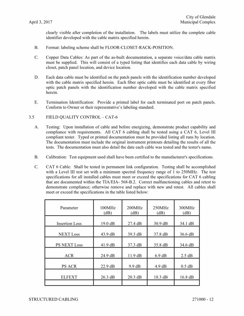
City of Glendale
April 3, 2017 Municipal Complex
STRUCTURED CABLING 271000 - 12
clearly visible after completion of the installation. The labels must utilize the complete cable
identifier developed with the cable matrix specified herein.
B. Format: labeling scheme shall be FLOOR-CLOSET-RACK-POSITION.
C. Copper Data Cables: As part of the as-built documentation, a separate voice/data cable matrix
must be supplied. This will consist of a typed listing that identifies each data cable by wiring
closet, patch panel location, and device location.
D. Each data cable must be identified on the patch panels with the identification number developed
with the cable matrix specified herein. Each fiber optic cable must be identified at every fiber
optic patch panels with the identification number developed with the cable matrix specified
herein.
E. Termination Identification: Provide a printed label for each terminated port on patch panels.
Conform to Owner or their representative’s labeling standard.
3.5 FIELD QUALITY CONTROL – CAT-6
A. Testing: Upon installation of cable and before energizing, demonstrate product capability and
compliance with requirements. All CAT 6 cabling shall be tested using a CAT 6, Level III
compliant tester. Typed or printed documentation must be provided listing all runs by location.
The documentation must include the original instrument printouts detailing the results of all the
tests. The documentation must also detail the date each cable was tested and the tester's name.
B. Calibration: Test equipment used shall have been certified to the manufacturer's specifications.
C. CAT 6 Cable: Shall be tested in permanent link configuration. Testing shall be accomplished
with a Level III test set with a minimum spectral frequency range of 1 to 250MHz. The test
specifications for all installed cables must meet or exceed the specifications for CAT 6 cabling
that are documented within the TIA/EIA- 568-B.2. Correct malfunctioning cables and retest to
demonstrate compliance; otherwise remove and replace with new and retest. All cables shall
meet or exceed the specifications in the table listed below:
Parameter 100MHz
(dB)
200MHz
(dB)
250MHz
(dB)
300MHz
(dB)
Insertion Loss 19.0 dB 27.4 dB 30.9 dB 34.1 dB
NEXT Loss 43.9 dB 39.3 dB 37.8 dB 36.6 dB
PS NEXT Loss 41.9 dB 37.3 dB 35.8 dB 34.6 dB
ACR 24.9 dB 11.9 dB 6.9 dB 2.5 dB
PS ACR 22.9 dB 9.9 dB 4.9 dB 0.5 dB
ELFEXT 26.3 dB 20.3 dB 18.3 dB 16.8 dB
City of Glendale
April 3, 2017 Municipal Complex
STRUCTURED CABLING 271000 - 13
PS ELFEXT 23.4 dB 17.3 dB 15.4 dB 13.8 dB
Return Loss 14.7 dB 11.7 dB 10.7 dB 9.9 dB
Propagation Delay 528 ns 527 ns 526 ns 526 ns
Delay Skew 40 ns 40 ns 40 ns 40 ns
Cables results of FAIL* (marginally fail) are not acceptable.
Cable results of PASS* (marginally pass) are only acceptable if confirmed by A/E.
Correct any links that do not PASS, and re-certify the link.
3.6 GROUNDING & BONDING
A. Provide a #6 BTC insulated conductor from each rack to ground bar located in room.
3.7 CLEANING
A. Upon completion of system installation, including outlet fittings and devices, inspect exposed
finish. Remove burrs, dirt, and construction debris and repair damaged finish, including chips,
scratches, and abrasions.
3.8 DEMONSTRATION
A. Train Using Agency’s maintenance personnel on procedures and schedules for start-up and
shutdown, troubleshooting, servicing, and preventive maintenance. Include training on fiber optic
splicing and connector attachment techniques.
B. Review data in operating and maintenance manuals. Refer to Division One Section "Operating
and Maintenance Data."
C. Schedule training with Using Agency, through the Architect/Engineer, with at least seven days'
advanced notice.
D. Training for maintenance shall incorporate concerns regarding the 20-year warranty stated in
Paragraph 1.6 of this section. The District’s personnel shall be able to maintain this system and
necessary training or certification shall be provided to avoid warranty issues.
3.9 ACCEPTANCE
A. Acceptance will be withheld until the following have been completed successfully:
1. Acceptance of all submittals.
2. Delivery of final documentation.
3. Successful testing.
4. Successful demonstration, including operation of systems using the cables, training and
manual review.
END OF SECTION 271000
April 14, 2017 Scenic Regional Library District
16-1161.00 Branch Library Projects
COMMUNICATION RACEWAY SYSTEM 271100 - 1
SECTION 271100 - COMMUNICATION RACEWAY SYSTEM
PART 1 - GENERAL
1.1 WORK INCLUDES
A. Contractor Provide:
1. Communication device backboxes (dimensions / height as indicated on plans).
2. Cable supports and Low-Voltage J-Hooks in accessible ceilings.
3. Telecommunications Terminal Board.
4. Telecommunications Ground Bar.
1.2 RELATED SECTIONS
A. Section 260526 – Grounding and Bonding for Electrical Systems.
B. Section 260529 – Hangers & Supports for Electrical Systems.
C. Section 260533 – Raceway and Boxes for Electrical Systems.
D. Section 260553 – Identification for Electrical Systems.
E. Section 262726 – Wiring Devices.
1.3 REFERENCES
A. NFPA 70 (2011) – National Electrical Code (NEC).
B. TIA 569-A (2004) – Commercial Building Standard for Telecommunications Pathways &
Spaces.
1.4 COORDINATION
A. Coordinate layout and installation of cable tray with other installations.
1. Revise locations and elevations from those indicated as required to suit field conditions
and as approved by A/E.
2. Storage and Handling: Avoid breakage, denting and scoring finishes. Damaged products
will not be installed. Store cable trays and accessories in original cartons and in clean dry
space; protect from weather and construction traffic. Wet materials will be unpacked and
dried before storage.
1.5 SUBMITTALS
A. Submit shop drawings and product data under provisions of Division One specifications.
B. Shop Drawings: Submit shop drawings indicating materials, finish, dimensions, accessories,
layout, supports, splices, and installation details.
C. Design Calculations: Verify loading capacities for supports.
April 14, 2017 Scenic Regional Library District
16-1161.00 Branch Library Projects
COMMUNICATION RACEWAY SYSTEM 271100 - 2
D. Coordination Drawings: Include floor plans and sections drawn to scale. Include scaled cable
tray layout and relationships between components and adjacent structural and mechanical
elements. Data presented on these drawings are as accurate as preliminary surveys and
planning can determine. Field verification of all dimensions, routing, etc., is directed.
1.6 PROJECT RECORD DOCUMENTS
A. Submit project record documents under provisions of Division One specifications.
B. Accurately record location of outlets and boxes, cable supports, and routing of raceway.
C. All closeout documents (Record Construction, O&M Manuals, Warranty documents and
Testing Reports, as necessary) shall be furnished to the A/E in electronic format.
1.7 OPERATION AND MAINTENANCE MANUALS
A. Submit all data under provisions of Division One specifications.
B. Operation Data: Include instructions for adjusting and operating the system.
C. Maintenance Data: Include repair procedures and spare parts documentation.
D. Each Operations and Maintenance manual will include original manufacturer’s equipment
specification sheets for all equipment installed on this project. The manuals will be tabulated
for quick reference between installed equipment cuts, equipment settings, operations data and
maintenance data.
PART 2 - PRODUCTS
2.1 COMMUNICATION DEVICE BACKBOXES
A. Sheet Metal Outlet Boxes: ANSI/NEMA OS 1, galvanized steel. Boxes shall be dimensioned as
indicated on drawings with cover as needed. Deep masonry type boxes shall be used in masonry
walls. Provide coverplate (with finish matching adjacent wiring devices) at every box. See
section 260534 for additional information.
2.2 LOW VOLTAGE J-HOOKS
A. Description: Pre-galvanized steel cable hook designed for support of low voltage cabling.
Provide appropriate cable hook configuration for location installed.
B. Size: 2" and 4" as required to accommodate cabling to be installed plus 50% spare.
C. Hooks shall be supported from structural elements with minimum two (2) mechanical fasteners
(screw or anchor). Devices designed for friction-fit attachment are not acceptable.
D. J-Hooks shall only be used above accessible ceilings, and shall be installed no greater than
every 6’-0” on-center and 18” from each wall partition.
April 14, 2017 Scenic Regional Library District
16-1161.00 Branch Library Projects
COMMUNICATION RACEWAY SYSTEM 271100 - 3
2.3 TELECOMMUNICATIONS (OR SYSTEMS) TERMINAL BOARD
A. Material: Plywood, treated or painted with fire resistive paint.
B. Size: 4’ x 8’ x 3/4” thick, in quantity as indicated on drawings.
2.4 TELECOMMUNICATIONS GROUND BAR
A. Busbar assembly shall include mounting brackets and fasteners (stainless steel construction), all
necessary lock and flat washers, and insulators.
B. Hole patterns on busbars shall accommodate two-hole lugs per the recommendation of BICSI
and ANSI 607-A standards.
C. Grounding Busbar shall be UL listed and approved by BICSI/TIA.
D. Ground bars identified as Main Ground Bars (“TMGB”) shall be 4”h x 20”l; Branch Ground
Bars (“TGB”) shall be 2”h x 12”l (both 1/4” in thickness). Provide the appropriate lug kits for
each type of bar.
E. Provide all insulated grounding conductors as indicated on drawings (minimum #6AWG).
PART 3 - EXECUTION
3.1 EXAMINATION
A. Verify that surfaces are ready to receive work.
B. Verify that field measurements are as shown on Drawings.
C. Beginning of installation means installer accepts existing conditions.
D. Examine substrates for compliance with requirements for installation tolerances and other
conditions affecting performance of cable trays. Do not proceed with installation until
unsatisfactory conditions have been corrected.
3.2 INSTALLATION
A. Support raceways, backboards, and cabinets under the provisions of Section 260529 –
Supporting Devices.
B. Install termination backboards plumb, and attach securely at each corner and at intervals no
greater than 36”.
C. Install outlet boxes at outlet locations shown on drawings. Provide raceway indicated to above
accessible ceilings. Provide bushing at termination of conduit above ceiling.
D. Install pull wire or polyethylene pulling string in each empty conduit.
E. Where indicated, Install faceplates on all sheet metal outlet boxes.
F. Install sheet metal outlet boxes 18 inches above finished floor U.N.O.
April 14, 2017 Scenic Regional Library District
16-1161.00 Branch Library Projects
COMMUNICATION RACEWAY SYSTEM 271100 - 4
G. Install sheet metal outlet boxes for wall phones 48 inches above finished floor.
H. Install sheet metal outlet boxes for future wireless access points (furnished by Owner) at 80
inches above finished floor (or height of notification appliance in corridor, room or area).
I. Provide ground bar connected to main building ground at termination backboards as indicated
on drawings.
J. Mark all backboards and cabinets with the legend "COMMUNICATIONS" or as indicated
under the provisions of “Electrical Identification”.
K. Provide conduit from empty wall boxes to above nearest accessible ceiling or as indicated on
drawings. Exposed ceilings or rooms with no ceilings shall not be considered accessible
ceilings, provide conduit to above nearest accessible ceiling or cable tray.
L. Telephone terminal board (TTB) to be located where shown on plans.
M. Clean all empty boxes after installation.
N. Install cable tray level and plumb according to manufacturer's written instructions, Drawings,
and referenced standards.
O. Cutting: Field-fabricate changes in direction & elevation by cutting & bending cable tray.
1. Cut cable tray wires in accordance with manufacturer’s instructions.
2. Cable tray wires must be cut with side-action bolt cutters with offset head to ensure
integrity of protective galvanic layer.
3. Remove burrs and sharp edges from cable trays.
END OF SECTION 271100
April 14, 2017 Scenic Regional Library District
16-1161.00 Branch Library Projects
FIRE ALARM AND SMOKE DETECTION SYSTEM 283111 - 1
SECTION 283111 - FIRE ALARM AND SMOKE DETECTION SYSTEM (WARRENTON ONLY)
PART 1 - GENERAL
1.1 WORK INCLUDES
A. Contractor shall provide an entire new fire alarm system for the building. The electrical
contractor shall provide all required components, devices, conduit, cable, and labor necessary
for the complete and successful installation of a fire alarm system including but not limited to
the following:
1. Manual pullstations
2. Detection Devices (including Smoke, Heat and Duct Detectors).
3. Smoke Detectors with Sounder Bases (primarily sleeping, i.e. bunk, rooms).
4. Notification Appliances (Visual and Audible/Visual signals).
5. Fire Alarm Control Panel (Existing Panel to Remain, Edwards 2400).
6. Interface to controlled equipment (air-handling units, Access Control System) including
addressable interface units, wiring (and needed raceway) and programming.
7. Fire alarm wire and cable.
B. The fire alarm system shall be fully operational by the dates indicated in Division One
specifications.
1.2 REFERENCES
A. NFPA 70 – National Electrical Code (NEC), 2008.
B. NFPA 72 – National Fire Alarm Code, 2007.
C. International Building Code (IBC), 2009.
D. Americans With Disabilities Act (ADA) 2010, and associated Accessibility Guidelines
(ADAAG).
1.3 REGULATORY REQUIREMENTS
A. System: UL- and FM- listed. Components for interaction and/or control with Fire Protection
pre-action system shall be FM-listed.
1.4 SYSTEM DESCRIPTION
A. Fire Alarm System:
1. Fire Alarm: Control Panel shall include Automatic and Manual Initiation, and Visual
and Audible signaling. System shall also include monitoring modules to monitor tamper
switches and flow switches, and control / relay modules to control indicated equipment
(electromagnetic door holders, air-handling unit shutdown, etc.).
2. Signal Transmission: Multiplex signal transmission. Initiation device circuits shall be
wired Class B, Style 4. Notification Appliance Circuits shall be wired Class B, Style Y.
B. Definitions:
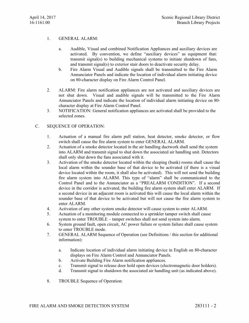
April 14, 2017 Scenic Regional Library District
16-1161.00 Branch Library Projects
FIRE ALARM AND SMOKE DETECTION SYSTEM 283111 - 2
1. GENERAL ALARM:
a. Audible, Visual and combined Notification Appliances and auxiliary devices are
activated. By convention, we define “auxiliary devices” as equipment that:
transmit signal(s) to building mechanical systems to initiate shutdown of fans,
and transmit signal(s) to exterior stair doors to deactivate security delay.
b. Fire Alarm Visual and Audible signals shall be transmitted to the Fire Alarm
Annunciator Panels and indicate the location of individual alarm initiating device
on 80-character display on Fire Alarm Control Panel.
2. ALARM: Fire alarm notification appliances are not activated and auxiliary devices are
not shut down. Visual and audible signals will be transmitted to the Fire Alarm
Annunciator Panels and indicate the location of individual alarm initiating device on 80-
character display at Fire Alarm Control Panel.
3. NOTIFICATION: General notification appliances are activated shall be provided to the
selected zones.
C. SEQUENCE OF OPERATION:
1. Actuation of a manual fire alarm pull station, heat detector, smoke detector, or flow
switch shall cause the fire alarm system to enter GENERAL ALARM.
2. Actuation of a smoke detector located in the air handling ductwork shall send the system
into ALARM and transmit signal to shut down the associated air handling unit. Detectors
shall only shut down the fans associated with it.
3. Activation of the smoke detector located within the sleeping (bunk) rooms shall cause the
local alarm within the sounder base of that device to be activated (if there is a visual
device located within the room, it shall also be activated). This will not send the building
fire alarm system into ALARM. This type of “alarm” shall be communicated to the
Control Panel and to the Annunciator as a “PREALARM CONDITION”. If a second
device in the corridor is activated, the building fire alarm system shall enter ALARM. If
a second device in an adjacent room is activated this will cause the local alarm within the
sounder base of that device to be activated but will not cause the fire alarm system to
enter ALARM.
4. Activation of any other system smoke detector will cause system to enter ALARM.
5. Actuation of a monitoring module connected to a sprinkler tamper switch shall cause
system to enter TROUBLE – tamper switches shall not send system into alarm.
6. System ground fault, open circuit, AC power failure or system failure shall cause system
to enter TROUBLE mode.
7. GENERAL ALARM Sequence of Operation (see Definitions / this section for additional
information):
a. Indicate location of individual alarm initiating device in English on 80-character
displays on Fire Alarm Control and Annunciator Panels.
b. Activate Building Fire Alarm notification appliances.
c. Transmit signal to release door hold open devices (electromagnetic door holders).
d. Transmit signal to shutdown the associated air handling unit (as indicated above).
8. TROUBLE Sequence of Operation:
April 14, 2017 Scenic Regional Library District
16-1161.00 Branch Library Projects
FIRE ALARM AND SMOKE DETECTION SYSTEM 283111 - 3
a. Indicate location of individual trouble alarm device in English on 80-character
display and provide visual and audible trouble signal at the Fire Alarm Control
and Annunciator Panel(s).
b. Manual ACKNOWLEDGE function at either type of panel silences audible
trouble alarm; visual alarm is displayed until initiating trouble is cleared.
9. DRILL Sequence of Operation: Manual DRILL function causes ALARM mode operation
to:
a. Sound and display local fire alarm notification devices.
b. Transmit signal to release door hold open devices.
c. Transmit signal to Fire Alarm system Annunciator Panels.
10. Alarm Reset and Silence: Key-accessible RESET function at the control panels
acknowledges alarm or trouble and resets system out of ALARM if alarm signaling
circuits have cleared. If signaling circuits have not cleared, the local panel audible signal
silences, the notification devices will be turned off, and an LED is lit. Subsequent alarms
or troubles shall cause the panels’ audible signal and the notification devices to operate
until silenced in turn. Restoration to normal of the signaling circuit shall extinguish the
associated LED and cause the panel audible signal to sound until the restoration is
acknowledged by switch operation.
1.5 QUALIFICATIONS
A. Equipment Supplier:
1. Existing System is a Edwards 2400 series.
1.6 SUBMITTALS
A. Submit shop drawings and product data under provisions of Division One specifications.
B. Provide project specific wiring diagrams, data sheets, and equipment ratings, layout,
dimensions, and finishes, and battery calculation charts.
C. Listing of all addressable detectors and intelligent modules to confirm new Control Panel
supports total number of addresses plus 20% spare in both categories.
D. Submit detailed project specific equipment requirements including sequence of operation.
E. Submit manufacturer's installation instructions.
1.7 PROJECT RECORD DOCUMENTS
A. Submit documents under provisions of Division One specifications.
B. Include plans, diagrams and details including locations of all control units, all field devices, all
wiring and of end of line devices.
C. Record Documents shall be furnished to A/E for delivery to Owner in both print and
April 14, 2017 Scenic Regional Library District
16-1161.00 Branch Library Projects
FIRE ALARM AND SMOKE DETECTION SYSTEM 283111 - 4
electronic format. Electronic format includes CAD drawings (AutoCAD version 2002 or
later) on compact disc. A/E will furnish Contractor and/or their supplier with all electronic
files for preparation.
1.8 OPERATION AND MAINTENANCE DATA
A. Submit data under provisions of Division One specifications.
B. Include operating instructions, and maintenance and repair procedures and Project Record
Drawings with manual.
C. Include manufacturer representative's letter stating that system is fully operational.
D. Include the system testing documentation in compliance with NFPA 72.
1.9 DELIVERY, STORAGE, AND HANDLING
A. Deliver products to site under provisions of Division One specifications.
B. Store and protect products under provisions of Division One specifications.
1.10 QUALIFICATIONS
A. Equipment Supplier: Company specializing in smoke detection and fire alarm systems with a
minimum of three (3) years documented experience.
B. Equipment Installer: Company factory-authorized to work on approved systems with five (5)
years documented experience (minimum) with manufacturer of system.
1.11 WARRANTY
A. The fire alarm system components shall be fully guaranteed for a period of one year beginning
on the date of substantial completion. Substantial completion will be granted after the system is
fully operational and all testing documentation has been completed.
B. The guarantee shall include the entire scope of work including all equipment, devices, materials,
cable/wire, software and installation.
C. The guarantee shall exclude acts of God, vandalism, physical abuse or operator misuse.
PART 2 - PRODUCTS
2.1 FIRE ALARM CONTROL PANEL
A. Manufacturers / Suppliers
1. Edwards 2400 Series
B. Fire Alarm and Smoke Detection Control Panels (FACP)
1. System Capacity and General Operation:
April 14, 2017 Scenic Regional Library District
16-1161.00 Branch Library Projects
FIRE ALARM AND SMOKE DETECTION SYSTEM 283111 - 5
a. The control panels shall provide sufficient capacity for the Analog Addressable
Smoke and Heat Detectors, Addressable Monitor and Control Modules, and all
other Intelligent/Addressable devices that are indicated on the plans and that are
necessary to make the system fully functional and 20% spare device capacity for
both the detector AND intelligent modules independently.
2. Each Fire Alarm control panel shall be provided with a locking door to prevent
unauthorized access to any function or control. The 80-character LED display shall be
visible through this door.
3. Each fire alarm control panel shall include a full featured operator interface control and
annunciation panel which shall include a backlit 80-character Liquid Crystal Display,
individual, color coded system status LEDs, and an alpha-numeric keypad for the Field
Programming and Control of the Fire alarm System.
4. All programming of the system shall be achieved without special equipment and without
interrupting the alarm monitoring functions of the Fire Alarm Control Panel.
5. The Central Processing Unit shall communicate with, monitor, and control all other
modules within the control panel. Removal, disconnection or failure of any control panel
module shall be detected and reported to the System Common Control Annunciator by
the Central Processing Unit. The Central Processing Unit shall contain and execute all
control-by-event programs for specific action to be taken if an alarm condition is detected
by the system. Such-control-by-event programs shall be held in non-volatile
programmable memory, and shall not be lost even if system primary and secondary
power failure occurs. The Central Processing Unit shall also provide a real-time clock
for time annunciation of all system displays. The Time-of-Day and date shall not be lost
if system primary and secondary power supplies fail.
6. The System Display shall be the system common control/annunciator, and shall provide
all the controls and indicators used by the system operator and may also be used to
program all system operational parameters. The Display Interface Assembly shall
contain, and display as required, the custom alphanumeric labels for all Intelligent
Detectors and Addressable Modules on an 80-character alphanumeric Liquid Crystal
Display. Such label information shall be stored in programmable non-volatile memory.
7. Activation of the system Test Switch shall initiate an automatic test of all
Intelligent/Addressable detectors in the system. The System Test shall activate the
electronics in each intelligent sensor, simulating an alarm condition and causing the
transmission of the alarm condition from that sensor to the Fire Alarm Control Panel.
The Fire alarm Control panel shall interpret the data from each sensor installed in the
system. A report summarizing the results of this test shall be displayed automatically on
the System Liquid Crystal Display.
8. Means shall be provided for adjusting the sensitivity of any or all analog intelligent
detectors in the system from the system keypad. Sensitivity range shall be within the
allowed NRTL window, and shall be a HIGH/MEDIUM/LOW selection. These levels
shall be adjustable from the Workstation Software located in the Command Center.
9. Each of the Intelligent/Addressable Smoke Detectors in the system shall be
independently selected and enabled to be an alarm verified detector. The Alarm
Verification Function shall be from 5-50 seconds and each detector shall be able to be
enabled/disabled during the field programming of the system, or anytime after system
turn-on.
10. The system will be able to generate and print a summary of all of the Detectors, Modules
and Pullstations that are currently active in the system. This printout will require
April 14, 2017 Scenic Regional Library District
16-1161.00 Branch Library Projects
FIRE ALARM AND SMOKE DETECTION SYSTEM 283111 - 6
password protection to prevent unauthorized user access, and will automatically print the
system report using keys. No computer expertise will be required to initiate the System
Report sequence.
11. The Fire Alarm Control Panel shall contain a History Buffer that will be capable of
storing up to 300 system output/input/control activations. Each of these activations will
be stored and time and date stamped with the actual time of the activation, until a
password authorized operator requests that the contents be displayed. The contents of the
History Buffer may be manually reviewed, one event at a time, and the actual number of
activations may also be displayed.
12. The Fire Alarm Control Panel shall automatically interrogate each Intelligent System
Detector and shall analyze the detector responses over a period of time. If any Intelligent
Detector in the system responds with a reading which is below 20% of normal limits (for
5 out of 6 polls), or above 80% of normal limits for a period of 24 hours, then the system
will enter the Trouble Mode, and the particular Intelligent Detector will be annunciated
on the System Display, and printed on the future System Printer.
13. When a fire alarm condition is detected and reported by one of the system initiating
devices or appliances, the following functions shall immediately occur:
14. 14. A local signal in the control panel shall sound.
15. The 80-character LCD display shall indicate all information associated with the Fire
Alarm condition, including: type of alarm point, its location within the protected
premises, and the time and date of that activation. All system output programs assigned
via control-by-event equations to be activated by the particular point in alarm shall be
executed including: Alarm Notification Devices, control relays for door release, elevator
and AHU shutdown.
16. The fire alarm control panel shall contain auxiliary contacts, one to close when the
system enters the trouble mode, and a separate auxiliary contact to close when the system
enters into alarm.
17. Power supply: Adequate to serve control panel modules, and all alarm signaling devices.
Include battery operated emergency power supply with capacity for operating system in
standby mode for 24 hours followed by alarm mode for 15 minutes.
2.2 INITIATING DEVICES
A. Manual Station: Double-action type, fabricated of metal or high-impact plastic, and finished in
red with molded raised letter operating instructions of contrasting color. Stations requiring the
breaking of a glass rod shall not be provided. Provide with keyed reset.
B. Smoke Detector: Comply with UL 268; the Photoelectric-Type Smoke Detectors shall be
Intelligent and Addressable, and shall connect with two wires to one of the Fire Alarm Control
Panel Signaling Line Circuits. The detectors shall use either a light obscuration or light
scattering principal to measure products of combustion and shall, on command from the
control panel, send data to the panel representing the analog level of products of combustion.
C. Smoke Detector for sleeping rooms: Comply with UL 268; The Photoelectric- Type Smoke
Detectors shall be Intelligent and addressable, and shall connect with two wires to one of the
Fire Alarm Control Panel Signaling Line Circuits. The detectors shall use the light scattering
principal to measure products of combustion and shall, on command from the control panel,
send data to the panel representing the analog level of products of combustion. The detector
shall be provided with a sounder base (connected to remote power supply as indicated on
drawings) that produces an interrupted 85 dBA (UL reverberant room) tone. Both audible
April 14, 2017 Scenic Regional Library District
16-1161.00 Branch Library Projects
FIRE ALARM AND SMOKE DETECTION SYSTEM 283111 - 7
(“horn”) and visual (“strobe”) notification shall be given locally when the unit senses smoke
in the room as well as under GENERAL ALARM. In rooms that contain visual notification
devices (ADA rooms), the smoke detector base shall also contain an auxiliary relay to activate
the combined audible/visual notification appliance.
D. Heat Detector: The Intelligent Heat Detectors shall be Intelligent and Addressable, and shall
connect with two wires to one of the Fire Alarm Control Panel Signaling Line Circuits. The
detectors shall use an electronic sensor to measure thermal conditions caused by a fire and
shall, on command from the control panel, send data to the panel representing the analog level
of such thermal measurements.
E. Duct Mounted Smoke Detector: Duct Smoke Detectors shall be addressable and analog
devices similar to the area smoke detectors except enclosed in an enclosure / housing rated for
duct application and supplied with sampling tubes sized for the duct.
F. Monitor modules shall be provided to connect any N.O. or N.C. dry contact device as shown.
The Monitor Module shall provide address setting and store an internal identifying code that
the Fire Alarm Control Panel shall use to identify the type of device.
G. Control Modules shall be provided to supervise and control the operation of one signal circuit
or as an addressable dry contact (form C) relay. The Control Module shall provide address-
setting means and store an internal identifying code that the Control Panel shall use to identify
the type of device.
2.3 SIGNALING DEVICES
A. Audible/Visual Signal: certifications shall include NFPA 72, UL 1971, and Americans with
Disabilities Act. Device shall be semi-flush type horn with white lettered FIRE on red device
body. Sound Rating 89 dB at 10 feet (minimum). Provide with integral strobe assembly and
flasher with candela rating as indicated on the drawings. Device shall be clearly marked with
strobe device intensity rating visible without unit disassembly or device removal. Devices
shall be capable of silencing the audible component while the visual component is still active,
on the same pair of NAC circuit wires.
B. Visual Fire Alarm System Signal: certifications include NFPA 72, UL 1971, and Americans
with Disabilities Act. Device shall be semi-flush strobe assembly and flasher with candela
rating as indicated on the drawings, with white lettered FIRE on red device body. Device
shall be clearly marked with strobe device intensity rating visible without unit disassembly or
device removal.
2.4 FIRE ALARM WIRE AND CABLE
A. Provide all fire alarm cabling as power-limited fire-protective signaling cable, plenum rated
(FPLP).
B. Initiating and Signaling Circuits:
1. Meets requirements of Article 760 of the NEC for power limited cable, including
required jacket marking.
2. Minimum wire gauge: #16 AWG solid copper.
April 14, 2017 Scenic Regional Library District
16-1161.00 Branch Library Projects
FIRE ALARM AND SMOKE DETECTION SYSTEM 283111 - 8
3. Number of pairs: 1 Pair, shielded.
4. Voltage rating: 300 volts.
5. Jacket material: Plenum rated.
6. Temperature rating: 105 deg. C in plenum.
7. Shielding: Overall foil shield with 22-gauge drain wire.
C. Notification Appliance Circuits (NAC) and Control Circuits:
1. Meets requirements of Article 760 of the NEC for power limited cables, including
required jacket marking.
2. Minimum wire gauge: #14 AWG solid copper.
3. Number of pairs: 1 Pair, unshielded.
4. Voltage rating: 300 volts.
5. Jacket material: Plenum rated.
6. Temperature rating: 105 deg. C in plenum.
2.5 NAMEPLATES AND LABELS.
A. Nameplates and labels shall be provided for all addressable devices. Nameplates and labels
shall be in accordance with Specification Section 260553 and mounted within the protective
cover for the device were applicable. Labels for ceiling mounted smoke or heat detectors shall
have 1/4" lettering and be mounted on the inside of the protective cover at the base of the unit.
The contractor shall take care to orient all nameplates so that they can be read from the floor.
Labels for pull stations and other wall devices shall have 1/8" lettering. These shall be secured
to the wall using tamper proof screws.
2.6 ADDITIONAL DEVICES
A. In addition to the devices indicated on the electrical drawings, Electrical Contractor shall
provide (5) additional single-input intelligent monitoring modules and (2) additional control
modules, plus all installation and programming labor, as well as all final connections. E.C.
shall also include an allotment (both material and labor costs) of 100’-0” of SLC (Fire Alarm
signaling line circuit) cabling, 50’-0” of 3/4” EMT conduit, and 25’-0” of 3/4” liquid-tight
flexible conduit, as well as all fittings, connectors, etc.
PART 3 - EXECUTION
3.1 INSTALLATION, GENERAL
A. Install system in accordance with NFPA Standards referenced in Parts 1 and 2 of this Section.
B. Connect fire alarm system initiating circuits to devices to be controlled by fire alarm.
Coordinate with equipment supplier.
3.2 EQUIPMENT INSTALLATION
A. Manual Pull Stations: Unless otherwise indicated mount semi-flush in recessed back boxes
with operating handles 48" above finished floor. For surface mounted devices, mount device
in surface box appropriately sized for device.
B. Smoke and Heat Detectors: Install detectors indicated to be ceiling mounted not less than 4”
April 14, 2017 Scenic Regional Library District
16-1161.00 Branch Library Projects
FIRE ALARM AND SMOKE DETECTION SYSTEM 283111 - 9
from a side wall to the near edge. Install detectors located on the wall at least 4” but not more
than 12”below the ceiling. For exposed solid joist construction, mount detectors on the
bottoms of the joists. Install detectors no closer than 3’-0” from air registers.
C. Horn/Strobe and Strobe: Install 80” above floor or 6” below the ceiling whichever is lower. If
architectural appurtenances (i.e. Lockers, Marker Boards, and Mirrors) interfere with device
mounting at this height, devices may be installed up to 96” above floor.
D. Duct Mounted Smoke Detector: Securely mount detector housing to duct and install sampling
tube. Seal all duct penetrations to provide an airtight installation. Modify associated
equipment’s starting mechanism to incorporate fan shutdown. Starting mechanism shall be
modified such that the fire alarm system will shutdown fan regardless of hand-off-auto switch
position.
E. Control modules and monitor modules: Mount within 3’-0” of device controlled/monitored.
F. Device Location Indicating Lights: Locate in the public space immediately adjacent to the
device they monitor.
G. Fire Alarm Control and Annunciator Panels: Surface or Flush mount as indicated on the
drawings with tops of cabinets not more than 5’-6” above the finished floor.
3.3 WIRING INSTALLATION
A. Wiring Method: Install wiring in accordance with Section 260519 - "Building Wire & Cable".
Contractor shall protect all edges of surface raceway to ensure that cable is not damaged
during installation.
B. Wiring / cabling may be installed open above accessible ceilings only; where rooms or areas
do not contain any ceiling (exposed structure) or inaccessible (“hard”) ceilings without
adequate access, fire alarm cabling shall be installed in conduit. Raceway and/or conduit shall
be painted to match adjacent surfaces. Install fire alarm cabling to structure (decking)
above accessible ceiling space.
C. Wiring within enclosures: Install conductors parallel with or at right angles to the sides and
back of the enclosure. Bundle, lace, and train the conductors to terminal points with no excess.
Connect conductors that are terminated, spliced, or interrupted in any enclosure associated
with the fire alarm system to terminal blocks. Mark each terminal in accordance with the
wiring diagrams of the system. Make all connections with approved crimp-on terminal spade
lugs, pressure-type terminal blocks, or plug connectors.
D. Cable Taps: Use numbered terminal strips in junction, pull or outlet boxes, cabinets, or
equipment enclosures where any circuit tap is made.
E. Alarm Wiring: For the low-voltage portion of the fire alarm system, install 75-deg C
insulation in wet, damp, or dry locations. Provide wiring operating at line voltage having
similar insulation.
F. Color Coding: Color code all fire alarm conductors differently from the normal building
power wiring. Provide one color code for alarm circuits wiring and a different color code for
supervisory circuits. Provide a color code for audible alarm indicating circuits different from
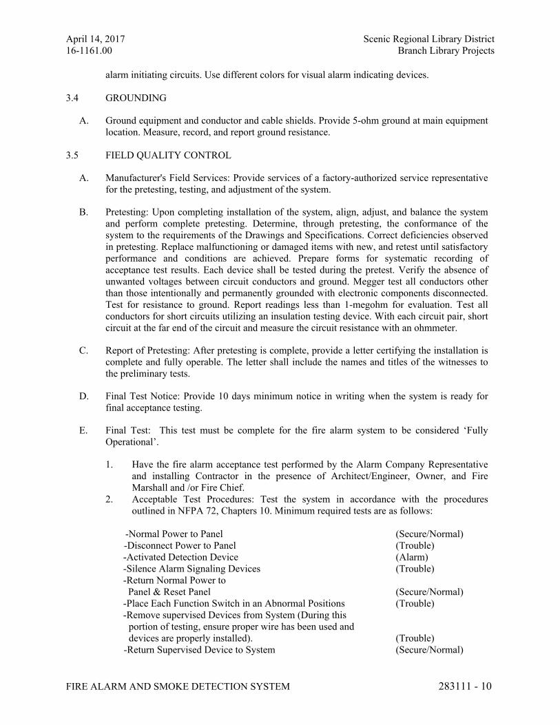
April 14, 2017 Scenic Regional Library District
16-1161.00 Branch Library Projects
FIRE ALARM AND SMOKE DETECTION SYSTEM 283111 - 10
alarm initiating circuits. Use different colors for visual alarm indicating devices.
3.4 GROUNDING
A. Ground equipment and conductor and cable shields. Provide 5-ohm ground at main equipment
location. Measure, record, and report ground resistance.
3.5 FIELD QUALITY CONTROL
A. Manufacturer's Field Services: Provide services of a factory-authorized service representative
for the pretesting, testing, and adjustment of the system.
B. Pretesting: Upon completing installation of the system, align, adjust, and balance the system
and perform complete pretesting. Determine, through pretesting, the conformance of the
system to the requirements of the Drawings and Specifications. Correct deficiencies observed
in pretesting. Replace malfunctioning or damaged items with new, and retest until satisfactory
performance and conditions are achieved. Prepare forms for systematic recording of
acceptance test results. Each device shall be tested during the pretest. Verify the absence of
unwanted voltages between circuit conductors and ground. Megger test all conductors other
than those intentionally and permanently grounded with electronic components disconnected.
Test for resistance to ground. Report readings less than 1-megohm for evaluation. Test all
conductors for short circuits utilizing an insulation testing device. With each circuit pair, short
circuit at the far end of the circuit and measure the circuit resistance with an ohmmeter.
C. Report of Pretesting: After pretesting is complete, provide a letter certifying the installation is
complete and fully operable. The letter shall include the names and titles of the witnesses to
the preliminary tests.
D. Final Test Notice: Provide 10 days minimum notice in writing when the system is ready for
final acceptance testing.
E. Final Test: This test must be complete for the fire alarm system to be considered ‘Fully
Operational’.
1. Have the fire alarm acceptance test performed by the Alarm Company Representative
and installing Contractor in the presence of Architect/Engineer, Owner, and Fire
Marshall and /or Fire Chief.
2. Acceptable Test Procedures: Test the system in accordance with the procedures
outlined in NFPA 72, Chapters 10. Minimum required tests are as follows:
-Normal Power to Panel (Secure/Normal)
-Disconnect Power to Panel (Trouble)
-Activated Detection Device (Alarm)
-Silence Alarm Signaling Devices (Trouble)
-Return Normal Power to
Panel & Reset Panel (Secure/Normal)
-Place Each Function Switch in an Abnormal Positions (Trouble)
-Remove supervised Devices from System (During this
portion of testing, ensure proper wire has been used and
devices are properly installed). (Trouble)
-Return Supervised Device to System (Secure/Normal)
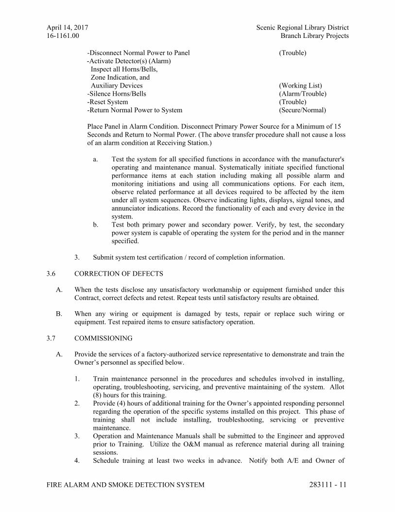
April 14, 2017 Scenic Regional Library District
16-1161.00 Branch Library Projects
FIRE ALARM AND SMOKE DETECTION SYSTEM 283111 - 11
-Disconnect Normal Power to Panel (Trouble)
-Activate Detector(s) (Alarm)
Inspect all Horns/Bells,
Zone Indication, and
Auxiliary Devices (Working List)
-Silence Horns/Bells (Alarm/Trouble)
-Reset System (Trouble)
-Return Normal Power to System (Secure/Normal)
Place Panel in Alarm Condition. Disconnect Primary Power Source for a Minimum of 15
Seconds and Return to Normal Power. (The above transfer procedure shall not cause a loss
of an alarm condition at Receiving Station.)
a. Test the system for all specified functions in accordance with the manufacturer's
operating and maintenance manual. Systematically initiate specified functional
performance items at each station including making all possible alarm and
monitoring initiations and using all communications options. For each item,
observe related performance at all devices required to be affected by the item
under all system sequences. Observe indicating lights, displays, signal tones, and
annunciator indications. Record the functionality of each and every device in the
system.
b. Test both primary power and secondary power. Verify, by test, the secondary
power system is capable of operating the system for the period and in the manner
specified.
3. Submit system test certification / record of completion information.
3.6 CORRECTION OF DEFECTS
A. When the tests disclose any unsatisfactory workmanship or equipment furnished under this
Contract, correct defects and retest. Repeat tests until satisfactory results are obtained.
B. When any wiring or equipment is damaged by tests, repair or replace such wiring or
equipment. Test repaired items to ensure satisfactory operation.
3.7 COMMISSIONING
A. Provide the services of a factory-authorized service representative to demonstrate and train the
Owner’s personnel as specified below.
1. Train maintenance personnel in the procedures and schedules involved in installing,
operating, troubleshooting, servicing, and preventive maintaining of the system. Allot
(8) hours for this training.
2. Provide (4) hours of additional training for the Owner’s appointed responding personnel
regarding the operation of the specific systems installed on this project. This phase of
training shall not include installing, troubleshooting, servicing or preventive
maintenance.
3. Operation and Maintenance Manuals shall be submitted to the Engineer and approved
prior to Training. Utilize the O&M manual as reference material during all training
sessions.
4. Schedule training at least two weeks in advance. Notify both A/E and Owner of
April 14, 2017 Scenic Regional Library District
16-1161.00 Branch Library Projects
FIRE ALARM AND SMOKE DETECTION SYSTEM 283111 - 12
training dates.
B. SOFTWARE
1. Contractor and Fire Alarm system manufacturer / supplier shall furnish complete
programming of system on compact disc at commencement of project. Provide this
information with O&M Manuals.
3.8 WARRANTY
A. General. The contractor warrants that all work provided under the contract will be in
conformance with the contract and free from defects in workmanship, materials and equipment
for a period of one (1) year or such longer periods may be specified in the contract documents,
except as provided below. Warranty time periods shall commence from the date of Owner
acceptance of the whole, or any part of the project.
B. Latent Defects. On demand by the Owner, at any time within the one (1) year period
following substantial completion or final acceptance, if applicable, the Contractor shall
promptly repair or replace all defective or non-conforming work resulting from, or
constituting, latent defects, fraud, fraudulent concealment or gross negligence. The Owner
and/or A/E will give timely notice of such defects.
C. Prompt Repair. Upon notice from Owner of such defects or non-conforming work, the
Contractor shall promptly visit the site within 48 hours in the company of a building
representative, and shall provide all labor, material and equipment to promptly repair or
replace the defective or non-conforming work. The repair shall include all adjacent work not
necessarily provided by the Contractor but damaged as a result of such defects or non-
conforming work, Owner may repair or replace such work and charge the cost thereof to the
Contractor. Work which is repaired or replaced by the Contractor shall be inspected and shall
be warranted by the Contractor in accordance with this Article. The warranties set forth
herein are in addition to all warranties or guarantees expressed or implied by operation of law,
statute or ordinance.
D. Commercial Warranties. The Contractor shall deliver all commercial warranties received from
manufacturers to the A/E prior to final completion but this shall not reduce Contractor’s
obligations under this article.
END OF SECTION 283111