sccr – overall panel short circuit current · pdf filesccr – overall panel short...
TRANSCRIPT

www.moeller.net
Xtra Combinations
Xtra Combinations fromMoeller offers a range of products and services, enabling the best possiblecombination options for switching, protection andcontrol in power distributionand automation.
SCCR – Overall Panel Short
Circuit Current Rating
– per NEC and UL standards –
Technical PaperDipl-Ing. Wolfgang Esser
Moeller addresses worldwide:www.moeller.net/addressE-Mail: [email protected]
© 2007 by Moeller GmbHSubject to alterationsVER0211-959GB MDS/Schrems 01/07Printed in Austria (02/07)Article No.: 110102
Xtra Combinations
Xtra Combinations from Moeller offers a range of productsand services, enabling the best possible combination optionsfor switching, protection and control in power distributionand automation.
Using Xtra Combinations enables you to find more efficientsolutions for your tasks while optimising the economic viability of your machines and systems.
It provides:■ flexibility and simplicity■ great system availability■ the highest level of safety
All the products can be easily combined with one another mechanically, electrically and digitally, enabling you to arriveat flexible and stylish solutions tailored to your application –quickly, efficiently and cost-effectively. The products are proven and of such excellent quality thatthey ensure a high level of operational continuity, allowingyou to achieve optimum safety for your personnel, machinery,installations and buildings.
Thanks to our state-of-the-art logistics operation, our com-prehensive dealer network and our highly motivated servicepersonnel in 80 countries around the world, you can count on Moeller and our products every time. Challenge us! We are looking forward to it!
VER0211-959_D_GB 27.02.2007 13:15 Uhr Seite U4

- 1 -
1 IEC = International Electrical Commission2 NRTL = Nationally Recognized Testing Laboratory3 CEC = Canadian Electrical Code
SCCR - Overall Panel Short CircuitCurrent Rating– per NEC and UL standards –
- a distinguishing feature of NorthAmerican Industrial Control Panels -
Introduction
Under short circuit conditions, doesthe entire power circuit hold up forthe time it takes the overcurrent pro-tective device to clear the fault? Doesone know how high the availablefault at the installation site can reach?Important questions indeed, and oneswhich a panel builder needs to prop-erly address in order to verify that themaximum overall short circuit ratingof an industrial control panel will besuitable and adequate for the applica-tion. The end-user would also need tobe assured that this withstand value isequal to, or higher than, what couldbe encountered at the installationsite. Prior knowledge of the end uselocation would be useful as well, sothat proper attention can be takenduring the engineering phase toinsure that both parties are in syncwith the local requirements.Unfortunately, that's not always pos-sible, particularly in the case of serial-ly made machinery destined for multi-ple, and geographically varied, loca-tions.
Machine manufacturers in NorthAmerica and the IEC - world, as wellas their suppliers of electrical equip-ment, have an urgent need to famil-iarize themselves with the concept ofshort circuit withstand capabilities fortheir installations, now that ShortCircuit Current Ratings for all powercircuits, including the primary supplyof control circuits, have become partof the marking requirement on therating labels of all industrial controlpanels (ICP) in the US. Power circuitsmake up the main electrical supplyand distribution circuits within apanel and ultimately serve to energizeand control all connected loads,including all motors and non-motorloads. Industrial Control Panels arecommonly used on a general basis forcommercial as well as industrial appli-cations. Special versions, for which a
short circuit current rating is also nec-essary, include Control Panels forIndustrial Machinery, and ControlPanels for Elevator Duty, just to namea few. This current situation con-fronting experts throughout NorthAmerica relative to control panels isrelatively recent, and was brought onby changes in the standards pertinentto those assemblies.
During standard UL/CSA testing,power circuit component manufac-turers have to insure that short circuitcurrent ratings are verified and can beapplied to their equipment. Ideallythen, industrial control panels wouldinclude only those power compo-nents which have been listed by aNRTL2 such as UL, and marked withshort circuit ratings. This would repre-sent the simplest basis by which toachieve a viable and reliable determi-nation of an overall control panelpanel short circuit rating. Control cir-cuits do not figure in the calculationnearly as much, since they are normal-ly derived from the secondaries ofcontrol transformers which are con-sidered electrically apart from the pri-mary circuit (see Diagram, Photo 1).
The topic of Short Circuit CurrentRatings as described in this paper is inline with current marking require-ments in the US. There is presently nodirect equivalent to UL 508A in theCanadian standards. It stands to rea-son, however, that the NEC and CEC3
will come to harmonize closely in thisregard, and that similar requirementswill become clearly defined andequally applicable in both countries.
Throughout the paper the term"Short Circuit Withstand", relative toControl Panels, is purposely avoidedand the standard itself makes a pointof highlighting that a Short CircuitCurrent Rating (SCCR) is not to beconfused with the Short CircuitInterrupting Rating of an overcurrentprotective device, i.e. it is not meantto indicate in any way a panel's abilityto interrupt or clear a fault. Rather, itforms the basis to establish an inher-ent performance and safety expecta-tion level for all the power circuitcomponents contained within a
panel, should the assembly be subjectto short circuit conditions. Importantcriteria to consider include the tripcharacteristics of the protectivedevice, as well as its clearing time andpeak let-through current and energyvalues. In this manner, the use of acurrent limiting molded case circuitbreaker in the feeder supply circuitcan be used to raise the overall shortcircuit rating of a panel or assembly.(see Photo 7). If the current limitingbreaker, by virtue of sufficiently lowlet-through values, proves capable ofproviding protection to the weakestof components included in the panel,the overall short circuit rating of thepanel can conceivably be raised tomatch the interrupting level of the cir-cuit breaker, provided all the addi-tional constraints stipulated in thestandard for that particular casewould have been met. It may beentirely worthwhile, therefore, toinstall a high performance device inthe supply circuit (e.g. a current limit-ing circuit breaker instead of a switch-disconnector or a molded caseswitch), even if it is initially more cost-ly, in order to permit the installationof more economical componentsdownstream. The word "Rating", ref-erenced in the in SCCR abbreviation,is more closely associated to theeffects of dynamic forces resultingfrom an abnormally high fault cur-rent, which make it inherently diffi-cult to pinpoint with accuracy theexact magnitude of the short circuitcurrent flow. In actual practice, shortcircuit levels are, for the most part,lower than calculated values. Thataspect is mostly related to a varyingamount of resistance present in theshort circuit path at any givenmoment. Thus, the word "with-stand", if it were assigned to a panelpower circuit component in this case,could be construed as misleading,since in actual fact, the level of shortcircuit current flowing through thecomponent is effectively lower inmost cases than the marked ratingwould imply.
It's always been the case in NorthAmerica that individual componentsin a motor starter combination can'tjust be arbitrarily put together for end

- 2 -
use (as is typically done in the IECworld under somewhat less constrain-ing fashion). Rather, specific compo-nents are always tested together as acombination, and the ensuing resultsare tabulated in the manufacturer'sthird party listing (UL) or certification(CSA) report. The ratings achievedthus provide a useful and indepen-dently verified data base of informa-tion to help coordinate the properapplication of combination motorstarters relative to short circuit condi-tions and available faults in installa-tions. [1] If, on the other hand, thecomponents are not tested together,then the general rule will continue toapply, namely, that the short circuitrating of the entire combination willbe predicated by the lowest ratedcomponent used in the motor starterassembly.
Power circuit components typicallyfound in control panels, and fulfillingdifferent functions, will often be asso-ciated with various levels and types ofshort circuit ratings. For example, acontactor doesn't have to feature ashort circuit interrupting rating, sincethat is the prescribed domain of theovercurrent protective device, such asa fuse or a circuit breaker. From the
point of view of high fault clearingcapabilities, the contactor wouldactually represent the weakest link inthe chain of power circuit compo-nents. On the other hand, it's also themost dependable performer, from theoperational viewpoint of switchingboth motor and non-motor loads reli-ably, as well as achieving long lifeunder normal service conditions. Inorder to be assigned a short circuitcurrent rating, a test is performed inwhich the contactor must be able towithstand a fault current for the timeit takes the protective device to clearwithout creating a shock or fire haz-ard in its immediate vicinity. Workingin coordinated fashion with the pro-tective device can thus lead to signifi-cant short circuit current rating levelsfor the contactor. The quicker the pro-tective device can clear the fault, thegreater the chance of being able toachieve a very high rating.
The magnitude of a short circuit cur-rent, which a contactor can safelywithstand, is certainly not unlimited.A critical aspect of the device's con-struction in this respect involves thelevel at which the dynamic forces pro-duced by the fault current are able toseparate the main contact surfaces
apart. Much of that is tied to relevantaspects of its design as well as to itsphysical size. As soon the fault leveldrops down to the value below thecurrent lift-off point of the contactor,the main contacts re-close automati-cally. During that time, and under par-ticularly unfavorable conditions, theburning-off of material through thearcing process can more or less lead towelding of the contact surfaces. Tothis effect, the IEC world has estab-lished Types 1, 2 and CPS levels ofshort circuit co-ordination as a meansto better define allowable damagesunder fault conditions. These co-ordi-nation levels are not yet officially partof the current North American motorstarter testing standards, however, itis possible for UL to test and evaluateper these IEC definitions and classifyequipment accordingly.
North American companies, particu-larly large concerns involved multi-nationally, are now coming acrossthese requirements more frequently,both as requirements for projectsabroad but also increasingly at homein applications for which the IEC defi-nitions have begun to make inroads.Many safety aspects of IEC standards,in particular the Machinery Directive
1 DISCL 1 L 1 T 1 1 FU-1
1 M-1 10 L
2 M-1
2 M-1
2 M-1
2 PB-22 PB-1 2 PB-2 1 LS
20 L
MTR1
MTR2
Branch Circuit 1
Branch Circuit 2
1 T Control Circuit Transformer
Class 2 Circuit
2 T Class 2 Transformer
Feeder Circuit
1 FU-2
1 FU-3
4 FU-1
5 FU-1
5 FU-2
3 FU-2
3 T
2 FU-2
2 FU-1
Power Transformer
4 FU-2
1 PB-1 1 PB-2
1 M-1
1 M-2 1 SOL
1 M-1 1 M-2
1 M-1
1 FS 1 CR-1
1 CR-1
L 2 L 2 T 2
L 3 L 3 T 3
Branch Circuit
Photo 1: Typical North American wiring diagram showing power and control circuit layout. The control circuit is galvanically separated fromthe main power circuit via a control circuit transformer. Only the power circuit portion is assigned a short circuit rating. The feedercircuit, with its more stringent requirements concerning electrical clearances, is marked off in yellow to the left of the dotted line.

- 3 -
standard for electrical equipment IEC60 204-1 [2], have evolved beyond thecurrent accepted norm in NorthAmerican standards, and have thusreceived a very positive response frommany end-users in the US.
No matter the location around theworld, the occurrence of a sizeablefault in an installation will require athorough evaluation on the part of anexpert and may, depending on theseverity, lead to a need for extensiverepairs. When testing for short circuitratings, it is permissible for certainpower components such as contac-tors to undergo extensive damageand for main contacts to weld. Thesedevices can then no longer bebrought back into service and need tobe replaced.In accordance with NEC 2005, Article409.110 [3], and UL 508A [4] a deter-mination of the overall Short CircuitRating for an industrial control panelis now mandatory, and the resultantvalue must be displayed as part of theelectrical rating information on thepanel's nameplate. The panel name-plate, usually constructed out ofdurable material, bears the manufac-turer's name as well as a summary ofthe panel's main electrical ratings. It isnormally affixed to the panel's dooror cover so that it is visible from theexterior. The electrical ratings are keyto insure proper connection of thepanel to its incoming supply powersource. In addition, the panel shouldbear a set of serialized UL- Industrialcontrol panel and panel enclosurelabels, which are normally affixed onthe inside of the cover or door aftercompletion of a final evaluation bythe authorized UL panel shop whichperformed the assembly.
A crucial requirement in properly ful-filling the new regulations involvesthe availability of qualified compo-nent and motor starter data from amanufacturer. It is always advanta-geous for a panel builder to purchasecomponents from a manufacturersuch as Moeller, who can offer both abroad and appropriate componentselection while at the same time elim-inate potential mix and match prod-uct compatibility issues in the deter-
mination of an overall rating for thecontrol panel assembly.
Industrial Control Panels per NEC2005
The latest edition of the NEC4 (NFPA5
70) went into effect on Jan 1st, 2005.That doesn't necessarily mean that itwas enabled across the US on thatdate. There are still regional differ-ences with respect to its adoption, notonly from state to state, but also fromregion to region within individualstate borders, down to counties,cities, local municipalities and town-ships. Thus, changes in the NEC canbe hard to come by on a full scalenational basis. As of March 2006, onlyabout half of the states had enabledthe 2005 Code, with 13 others stillrecognizing the 2002 version. Fourare still operating on the 1999 Code,while the rest of the nation has yetolder versions of the NEC offically onthe books. The delay in implementa-tion of these new codes and stan-dards can often lead to the followingclaim commonly heard amongstexporters: "We supplied equipmentto North America and didn't have asingle problem, even though we musthave clearly been in violation of atleast a few of the major rules. Theonly appropriate reply to that shouldbe: "How lucky you were". At thesame time, this slow integrationprocess on a regional basis can lead toacceptance problems for electricalinnovations, even when they areapplied per newly implemented regu-lations, because the equipment mightnot be recognized locally as truly rep-resenting the latest developments intechnology. Worse yet, it may noteven be accepted. The recognition ofUL 508A, on the other hand, seemsbroader and appears to have under-gone a much more rapid acceptanceprocess. The newly introduced regula-tions on short circuit marking require-ments described herein should notonly alleviate the burden of responsi-bility placed upon local electricalinspection authorities but also accel-erate implementation of the newrequirements on a national basis.
Apart from regional differences in the
adoption of newly introduced regula-tions, the final approval by local elec-trical inspectors (AHJ6) still remains anunpredictable risk in many respects. Inthe US alone there are literally thou-sands of jurisdictions subject to localrulings and interpretations. Differingviewpoints are bound to emerge inview of the sheer number of regula-tions deemed to be pertinent andapplicable. For this reason, it is imper-ative that strict adherence to thenational equipment standards bemaintained, since mandated changesin electrical installations otherwisedeemed ready for commissioning canbe both difficult and expensive. Inextreme cases, fully scrapping thenon-compliant assembly and replac-ing it with an entirely new system mayend up as the only viable solution. Theapproval process of electrical equip-ment, conducted by the manufacturerin the country of export origin, auto-matically guarantees a high degree ofacceptability. Each UL listing labelhelps to relieve the local electricalinspector's personal burden ofresponsibility with respect to approvalof electrical equipment. An absolutepromise of a trouble-free acceptanceprocess in North America may be hardto come by, but taking the necessarysteps to properly select and applyelectrical equipment per local rules isthe next best thing to securing a guar-antee for a smooth and timely out-come.
This paper deals principally withassemblies falling under the GeneralUse category and which are built inlisted factories (factory assembled)(Photo 2). Specialized custom con-trols which are part of, or subsequent-ly added to, a field assembly, such asfor on-site lighting or air-condition-ing, are not part of this generaloverview and may be subject in anycase to additional requirements locat-ed in specific Articles throughout theelectrical codes. Likewise, there arecustom controls that address specificloads or types of equipment (specificuse Industrial Control Panels), andwhich must be designed and installedper Code with particular attention torequirements pertaining to the appli-cation. Examples of these include con-
4 NEC = National Electrical Code®5 NFPA = National Fire Protection Association, www.nfpa.org6 AHJ = Authority Having Jurisdiction

- 4 -
trol panels for Industrial Machinery,Crane control, Elevator control etc...Table 409.3 of the NEC describes themost important ones, along with therelevant article associated to theapplication.
A definition of Industrial ControlPanels (identical with the one foundin UL 508A) is provided in Article409.2 of the NEC. In connection withthe definition, the Code also men-tions the need to consult other appli-cable requirements specific to certainloads and specialized custom controlassemblies (refer also to [5]). Themajority of control panels, in whichtypical Moeller components would beinstalled, would fall under the afore-mentioned definition. Individuallycustomized industrial control panels,especially those with a highly auto-mated control circuitry content, cer-tainly represent a different breed of
assembly than arguably more solidlybuilt, and short circuit rated, construc-tions like conventional Motor ControlCenters MCCs, on the other hand,mainly feature power circuit compo-nents, and typically include compara-tively little in the way of intricate con-trol circuit functionality [6]. MCCs arebuilt and designed in the US to UL845.
There exists a number of listing possi-bilites for industrial control panels. Itis possible to obtain approvals for:
Empty industrial control panelenclosures with various environ-mental ratings.Enclosed industrial controlpanels.Open industrial control panels,which become housed in suitablyrated enclosures at a later stageof assembly.
Requirements of NEC 2005, Article409 (Industrial Control Panels)
The latest Article 409 is divided intothe following sections: "General","Installation" and ConstructionSpecifications". The Article makesinstallation recommendations inorder to insure that listed equipmentcan be combined and installed into anenclosure in such a way as to providea safe and Code compliant assemblyfor a variety of industrial and com-mercial applications. The scope ofIndustrial Control Panels can rangefrom very elementary single motorstarter and control apparatus to high-ly complex process automationassemblies.
In addition to providing the abovementioned definition of an industrialcontrol panel, Code Article 409 goeson to describe general requirementsfor the proper calculation of panelcable ampacities. A properly selectedsupply conductor cross-section for acontrol panel takes into account thesum of all connected loads and fea-tures an overall ampacity not lessthan:
125 % of the full load current rat-ing of all resistance heating loads,plus: 125 % of the full load current rat-ing of the largest motor in thegroup, plus: the sum of the full load currentratings of all other motors andthe rest of the loads that may bein operation at the same timebased on their duty cycle.
The factor of 1.25 is based on theactual load which is connected andsupplied. Future expansions which areeither planned or may be implement-ed at a later date are not addressed bythe additional reserves provided usingthis calculation. Additional loadswould also be subject to the 1.25 fac-tor and may necessitate a re-sizing ofthe supply conductor. Once the mini-mum ampacity requirements for thesupply conductor have been estab-lished, a suitable feeder overcurrentprotective is selected accordingly.
Control panels for industrial machin-ery in the US, per NEC Art. 670 andUL508A, would require the provisionof a supply circuit disconnectingmeans, as is the case with electrical
Industrial Control Panels are defined as an assembly of standard and/orcustom arrangement of two or more components in the power circuit,such as:
Motor starters, contactors, overload relays, circuit breakers, motorprotective switches, drives,and the associated control circuitry portion, which commonly includeselector switches, operating and signaling devices, timers and controlrelays. Associated wiring and terminal blocks are also considered part of thepanel per the definition. Industrial Control Panels under this Article operate at 600V or less.
They do not include the controlled equipment or machinery.
Photo 2: Example of a machine equipped with an industrial control panel. There are addition-al standards related to the above pictured machine which are relevant to the entireassembly, but these are beyond the scope of the topic addressed in this paper.

- 5 -
controls for industrial machinery perthe IEC/EN standard EN 60 204-1 [2].Article 409 further describes require-ments for enclosures and bus bar sys-tems, as well as the need to provideadequate wire bending space, partic-ularly in the area of the main incom-ing supply terminals. Control panelscan also be installed at the point ofentry of an electrical supply circuit, inwhich case they would need to bedeemed additionally suitable asService-Entrance Equipment. In thearea of industrial machinery, the needfor industrial control panels markedsuitable for service-entrance is lesslikely to occur.
Marking per NEC 2005, Article409.110
Article 409.110 of the NEC deals inmore specific terms with the thematicelements covered in this paper. Onesignificant aspect of Short CircuitCurrent Ratings involves the interac-tion of various components in thepower circuit under actual short cir-cuit conditions. Even with the avail-ability of extensive technical data onindividual components as well as theexpertise, either on the part of aninspector or professional engineer, toevaluate the information, it is impor-tant to realize that the tremendousdynamic and thermal forcesunleashed by a large overcurrent canstill often yield unpredictable results.
For example, a motor protectiveswitch and a contactor in a motorstarter branch circuit will both com-bine with each other to clear a fault.There exist today, particularly for highfault conditions, switching and pro-tective devices that have been espe-cially optimized for the purpose.Current limiting circuit breakers(Photo 3), safely clear a short circuitcurrent within the first half cycle ofthe initiated fault. This quick reactiontime insures that only a small portionof the damaging energy associated tothe overcurrent will be let through. Avery good thing, since the full bruntof the let-through energy associatedto the prospective fault current wouldotherwise be highly destructive.Moeller also purposely incorporatesfuseless current limiting designs,which feature extremely quick-actingbreak apart contacts, into certain con-trol components such as contactors in
order to produce a high performancemotor switching controller. A smallmagnetic trip coil is also included tofurther enhance the opening actionof the fast acting contact assembly(Photo 4). This type of switchingdevice can thus be installed in circuitswith much higher available fault lev-els and will noticably limit the let-through energy under short circuitconditions, thus greatly minimizingpotential damage to assemblies andloads downstream (Photo 5).
This type of dynamic co-dependencebetween components under faultconditions cannot be readily ascer-tained by comparing rating labels, ormaking paper calculations. As a rule,Moeller does perform highly complexcomputer simulations during thedesign stages in order to support itsdevelopment planning. Nevertheless,it is still every bit as necessary to doextensive testing, some of it inten-tionally destructive, in our high powerlab facility to assist these designefforts, as well as provide the neces-sary documentation which willbecome part of the approval process.In testing, as well as in practice, thenominal voltage plays a very crucialrole in the amount of energy impart-ed to the arc. Higher fault levelsencountered at installation sites, com-bined with relatively high voltage lev-els, such as in Canada with 600 V, 60Hz, put a tremendous burden on thedesign of modern switching and pro-tective devices. Everyone involvedwith electricity should have theopportunity at least once in their life-time to witness a live high fault shortcircuit test in a lab, followed by aviewing of the event on a high speedcam recorder, in order to fully experi-ence first hand the tremendous forcesproduced by magnetic fields associat-ed to fault currents. These are power-ful enough to easily rattle and bend
Photo 3: Modern current limiting MoldedCase Circuit Breakers Type NZMwith short circuit interrupting rat-ings established per the NorthAmerican norms at levels up to100 kA rms sym @ 480VAC and 50 kA rms sym @ 600VAC.
Photo 4: Motor and cable protective switch PKZ2/ZM-.. mounted directlyto its custom contoured current limiting module CL-PKZ2. Theexterior housing of the current limiting module is essentiallyidentical to the contactor module, which is similarly mounteddirectly to the switch.
L1 L2 L3
T1 T2
Q1
T3

- 6 -
solid copper bus bars as thick as aman's arm.This shows that it is not only correct,but essential to provide local electricalinspectors (AHJ) with nameplate dataon the overall short circuit ratings ofcontrol panels so that they can makebetter informed decisions on theoverall suitability of these assembliesin electrical installations. It's also vitalinformation to have on record in theevent of future changes which mayimpact the ratings established at thetime of original commissioning. This isespecially true should the panel andmachine have to be physically re-located and/or when there arechanges in the supply feed to theassembly. At the root of these ratingsare series of complex and comprehen-sive tests. It's advantageous, there-fore, if the majority of components inthe panel can be derived from thesame source since the manufacturerwill likely be able to provide the nec-essary ratings documentation pertain-ing to individual components as wellas those related to motor starter andassembly combinations. For example,in the case of more modern controlpanel designs in which motor starters
are assembled onto busbar adaptersand fed via bus bar systems, the entireassembly, including the bus system,would have to undergo a comprehen-sive testing verification process. Onprinciple, any power circuit compo-nent in the chain could potentially bethe weak link. The bottom line withrespect to Short Circuit CurrentRatings for Industrial Control Panels isto essentially verify that a potentialfault in the panel will be properlycleared and not cause a hazardouscondition in its vicinity. This wouldespecially include the risk of fire andpotential harm to personnel workingin close proximity to the equipment.The majority of approval tests must beperformed in enclosures. Other thanCode imposed allowable wire bend-ing space there are no limitations onminimum enclosure size requirementsfor starters and assemblies used intesting, but the overall volume has tobe published and taken into consider-ation during the control panel engi-neering design stages. Enclosures ofequal or greater volume and compa-rable quality must figure into theplanning. It's neither necessary norappropriate to add individual compo-
nent volume requirements, but in theend it's required to provide adequatefree room to insure that proper wiringspace, pressure relief and tempera-ture rise are kept within permissiblevalues as allowed by the standards.Generally speaking, the amount offree space required in North Americancontrol panels for wiring and servic-ing purposes is greater than compara-tive panels in the IEC world.
During the course of evaluation toestablish short circuit ratings there is anatural tendency to focus solely onthe maximum available fault currentat the installation site. Although thatis certainly a major consideration, it'salso important in an overall assess-ment to consider the impact of lessermagnitude fault currents, which onecan argue would be more prevalent,and the likelihood that they maycause a protective device to reactmore slowly and not be sufficientlyresponsive. Low level overcurrentscould potentially lead to the presenceof hazardous touch voltages onaffected circuit components andenclosures, should the fault beallowed to linger and not be clearedquickly enough. Typical ground faultcurrent provisions on protectivedevices are generally more prevalentin North America than in Europe as ameans to minimize fire and shockhazards in this respect. In spite of therelatively higher settings of equip-ment ground fault detective means,which can reach into the hundreds ofamperes depending on the nominalframe size rating of the protectivedevice, these values can still lie quitebelow the response currents of typicalthermal and magnetic trip mecha-nisms, which would normally notrespond at these relatively lower lev-els of fault currents. This represents apractical way of enhancing protectionat levels lower than the protectivedevice's normal trip response time.
Per UL508A, Par 52.1 (General Use),and 67.1 (Industrial Machinery), a vis-ible and properly positioned IndustrialControl Panel nameplate needs toinclude essential information on thepanel such as:
The nameplate rating label nowneeds to also include the following
îD[kA]
x=� � � �2 30
10
5 10ms
îD[kA]
y=� � � �2 100
14
1,9 10ms
Photo 5: Without a current limiter, the motor and cable protective PKZ 2 switch would only besuitable for circuits with a potential available fault of up to 30kA (photo at left). Useof the current limiting module enables the switch to be installed in circuits with po-tential faults of up to 100kA. In spite of this higher fault current, the let-throughenergy associated to the fault, which subjects the assembly to highly destructiveforces in a short circuit, would be less. (photo at right). The shaded areas under thecurves reflect the actual I2t values. In addition, all the power circuit elements in thefaulted circuit, e.g. conductors, motor, would be spared. The above reflects IEC data,although similar results are also achievable under North American testing conditions.

- 7 -
text, or an equivalent wording:
"Short circuit current: ... kA rms7 symmetrical,
... V maximum".
If a High Fault Short Circuit Rating isprovided, the size and type of the pro-tective device needed to achieve therating is also required to be markedon the nameplate (per UL 508A, SB5.1) in the event that the protectivedevice is not provided in the panel,and is intended to be mounted in thefield. In this respect, it may also benecessary to add an additionalWarning marking to the panel.
When the main overcurrent protec-tion in a control panel for IndustrialMachinery is intended to provide pro-tection for the supply conductors andthe machine, the panel needs addi-tionally to be marked as follows:
"Supply conductor and machineovercurrent protection provided atmain supply terminals"
The short circuit interrupting rating ofa built-in incoming protective devicewill no longer appear on the panelnameplate because it can often leadto the misconception that it repre-sents the rating of the overall controlpanel. This change will also apply toIndustrial Machinery panel name-
plates per NEC Article 670.3.Contactors, Drives, Motor protectiveswitches and Motorstarter-Combinations all have to be markedwith their own short circuit ratingsper NEC 430.8, either on their ownrating labels (which is often the mostconvenient way, especially for individ-ual components) or elsewhere as per-mitted by the NEC.
Determination of the control panelshort circuit rating
NEC article 409.110 indicates that theshort circuit rating of an industrialcontrol panel is based on either of thefollowing:
The short-circuit current rating ofa listed8 and labeled9 assembly(similar in many respects to a"Type-tested' combination), or:The short-circuit current ratingestablished using an approvedmethod.
The NEC explicitely mentionsSupplement SB of UL 508A (1st edi-tion-2001) "Short Circuit CurrentRatings for Industrial Control Panels"as an example of an approvedmethod. The supplement has beenrecently updated, and a newer ver-sion dated September 2005 is now inplace. Marking requirements for ULlisted short-circuit current rated con-
trol panels became effective as ofApril 25, 2006. The UL 508A standardfor Industrial Control Panels enjoysthe broadest from of acceptance andrecognition amongst panel buildersthroughout the US. The importantaspect remains that the short-circuitrating of the panel and/or the assem-bly be equal to, or greater than, themaximum available fault currentwhich the installation site powersource can deliver. The ability to makethis determination at the point ofconnection is often beyond the capa-bilites of the panel builder and theelectrical manufacturer of compo-nents and motor starter assemblies.The ultimate responsibilty for properapplication of the equipment and forverifying the suitability of the installa-tion with respect to the panel name-plate rating remains in the hands ofthe property owner and the end-user.Of course, the local electrical authori-ties (AHJs) are also part of this processby helping to establish and validateoverall compliance with the NEC andlocal code requirements. Generally speaking, a calculation ofthe short circuit power available atthe secondary terminals of the distri-bution transformer (Table 1) will yieldan overall conservative value. Theactual levels available downstreamwould diminish somewhat because ofdamping in the electrical feeder path-ways.
7 rms = root mean square is analogous to the term Effective Value used in the IEC world8 LISTED = Equipment, published in a list by an organization that is acceptable to AHJs, that maintains periodic evaluations and whose list-
ing states that appropriate product standards have been met and are deemed suitable for the purpose.9 Labeled = Equipment, to which a label or a mark by an organization that is acceptable to AHJs has been attached, and which verifies its
compliance with the appropriate product standards for which it has been Listed.
Panel nameplate
The manufacturer's name or authorized designation and the particular factory's identification tag. (This can also be agood form of advertising for the manufacturer's qualified assembly locations).Panel Type marking if appropriate, e.g. "Control panel for Industrial Machinery".For each supply source: Nominal voltage (slash ratings, e.g. 480Y / 277 V, if appropriate). Nominal frequency, number ofphases and total full-load amperes.Full Load Ampere rating of the largest motor.Rated current of the largest resistive load (Industrial Machinery).Short Circuit Current Rating of the control panel. Short Circuit Rating of the main overcurrent protective device if provided (NFPA 79, UL508A 67.1.2).If the overcurrent protective device associated to a high fault control panel SCCR is not provided, and is to be installed local-ly, a marking on the nameplate must show the type of overcurrent protective device necessary for the high fault rating.If applicable, a marking indicating suitability as "Service Equipment" (point of incoming energy supply, with mainDisconnect Switch) Electrical wiring diagram number, or the index number to the electrical drawings.If applicable, the index number to the installation drawings.Enclosure environmental Type rating (e.g. Type 12, 4X, 3R etc...)
The enclosure must be marked with a North American environmental rating. If an enclosure is not marked with a recogniza-ble environmental rating, it will always default to the lowest rating possible, i.e. Type 1.

- 8 -
The provision of a control panel shortcircuit rating can also represent aform of legal protective function forthe OEM10, the machine manufactur-er and the panel builder, in the eventthat local installation requirementsare not made known during the engi-neering stage or at the time of com-missioning. The rating, clearly visibleand displayed on the panel name-plate, acts as verification of the maxi-mum short circuit rating for which theassembly is suitable. The SCCR canalso become a prominent part of thequotation presented to the end-userat the time of bidding.
Supplement SB of UL 508A
The UL 508A Standard for Safety enti-tled "Industrial Control Panels" wasreleased in 2001 by the Northbrookoffice of Underwriters LaboratoriesInc., in Northbrook, IL, USA. It is thede-facto authoritative safety standardon the design and engineering ofcontrol panels in the US. The currentedition contains all the updates andrevisions issued in September 2005.This would include the most recentchanges to the afore-mentioned sup-plement SB specifically dealing withshort circuit ratings for control panelswhich became effective April 25th of2006. The September 2005 set of revi-sion includes at least 40 additionalrequirement changes which are
scheduled to take effect in March of2007.In the 2005 NEC the Supplement SB isthe only document to be singled outas an approved method for establish-ing "Short Circuit Current Ratings forIndustrial Control Panels" (refer toTables 2a/b through 2e/f). Such amention in the NEC naturally providesthe Supplement with pre-eminenceover other comparable methods.
A design engineer has certainlyalways needed to take into considera-tion potential fault currents whenproperly selecting and applyingpower circuit components in an instal-lation. As such, not much haschanged from this basic task and
requirement. There is now, however,an additional need to make an evenmore thorough design analysis of thecircuit so that all the weakest ele-ments can be properly identified andincorporated into the overall calcula-tion. In order to make a meaningfulcomparison between the availablefault and the suitability of the compo-nent or components in question, adesign engineer can rely on:
The SCCR marked on listed (e.g.UL-Listed) and properly labeledcomponents and assemblies, orAn approved method to reliablyestablish the SCCR of the engi-neered assembly or panel inquestion.
As a general rule, the short-circuit rating (SCCR, in kA) of all powercircuit components in the panel, as well as of the control circuit sup-ply, shall be equal to or greater than the maximum available fault cur-rent [in kA] which can be present on the incoming supply terminals ofthe panel at the point of installation.
When using a current limiting protective device the short circuit burdenis greater on its supply side than it is on its load side. A good indicator ofthe current limiting effect is the let-through current of the protectivedevice. The use of current limiting devices greatly reduces the require-ments placed upon components under fault conditions in the power cir-cuit downstream. Components don't need to deal with a magnitude ofcurrent quite as high as in the supply side circuit.
10 OEM = Original Equipment Manufacturer
Table 1: Continuous current and and short circuit current ratings of typical North American power transformers.Ik'' = Initial transformer short circuit current when connected to a system with unrestricted short circuit capacity.
Short circuit ratings of typical North American 3 phase power transformers
240 V, 60 Hz 480 V, 60 Hz 600 V, 60 Hz
3 Phase Impedance Continuous Short Circuit Continuous Short Circuit Continuous Short CircuitPower rating Current Rating “Ik” Current Rating “Ik” Current Rating “Ik”
Rating Uk RatingkVA % A kA A kA A kA
300 5 722 14,4 381 7,2 289 5,8500 5 1203 24,1 601 12,0 481 9,6750 5,75 1804 31,4 902 15,7 722 12,6
1000 5,75 2406 41,8 1203 20,9 962 16,71500 5,75 3609 62,8 1804 31,4 1444 25,12000 5,75 - - 2406 41,8 1924 33,52500 5,75 - - 3008 52,3 2405 41,83000 5,75 - - 3609 62,8 2886 50,2

- 9 -
Table 2 a/b: Determination of the Short Circuit Current Rating according to UL 508A Supplement SB

- 10 -
Table 2 c/d: Determination of the Short Circuit Current Rating according to UL 508A Supplement SB

- 11 -
Table 2 e/f: Determination of the Short Circuit Current Rating according to UL 508A Supplement SB

- 12 -
In the past, such a comparison wouldhave often been done solely with theprotective devices in mind, and less inconsideration of industrial controlequipment and miscellaneous ele-ments located downstream in thepanel. In all likelihood, the ratingappearing on the nameplate wouldhave simply reflected the interruptingor short circuit rating of the main dis-connecting means. From that stand-point, the engineering design require-ments have certainly become morecomprehensive. It follows that theprocess by which ratings are deter-mined should also be properly docu-mented by the design engineer inorder to facilitate the eventual com-misioning and approval of the controlpanel at the installation site. It is thushighly recommended, either in ledgeror block form, to create an SCCR reg-ister of all the power circuit compo-nents as well as the control circuitsupply rating (Photo 6)) in order tofacilitate the overall determination ofthe panel short circuit rating. Table 3attempts to help the process by pro-viding a checklist of sorts to arrive atratings. These design steps are also anecessary part of the engineeringassociated to Control Panels forIndustrial Machinery.
This evaluation process is certainlyhelped by the fact that NEC Article430.8 actually requires short circuitmarkings on power circuit compo-nents and motor starter assemblies.These would include mostly contac-tors, motor starters, drives etc...essen-tially all the power components suit-able for switching and controllingmotor branch circuits.
It's worth noting initially that theSupplement differentiates between a"Standard SCCR" and a "High FaultSCCR" with respect to Motor con-trollers. A "High Fault SCCR" applieswhenever the short circuit ratingvalue assigned to the component orassembly is greater than the"Standard SCCR" shown in Table SB4.1 the standard. The table alsoassigns assumed maximum short cir-cuit ratings to listed or recognizedcomponents which are otherwiseumarked. Those values are rather con-servatively assigned and thus tend tobe on the low side. (Refer to Table 4
of this paper for excerpts out ofSupplement Table SB4.1). Withrespect to internal wiring connec-tions, the standard points out theneed to follow manufacturer's speci-fied instructions for torquing orcrimping all terminals of power circuitwiring connectors and components.
There are additional references to theovercurrent protection requirementfor control circuits which are directlytapped from the feeder or from thebranch circuit. Specifically, the stan-dard differentiates between:
A control circuit which is con-nected directly to the Feeder viaa BCPD11, either with or withouta control circuit transformer orpower supply, or: A control circuit which is directlytapped from the load side of aMotor Branch Circuit ProtectiveDevice.
In the former, the short circuit ratingof the branch circuit protective devicemust not be less than the overallpanel SCCR. In the latter, the short cir-cuit rating of the branch circuit pro-tective device needs to be included inthe determination of the branch cir-cuit short circuit rating (SB 4.4.1 undSB 4.4.4 a).
The Supplement SB defines severalsteps to follow in the determinationof the overall short circuit rating(SCCR) of the control panel:
1.) The first thing to do is to estab-lish the short circuit ratings ofindividual power circuit compo-nents. This will be a value inkiloamps at a particular voltage,and is applicable to all powercomponents aside from a fewminor exceptions.
To accomplish this, the following3 alternative methods are pre-sented: a.) Finding the SCCR informa-
tion on the component rat-ing label, or on the accompa-nying product documenta-tion provided by the manu-facturer.
b.) Using the assumed short cir-
cuit rating of the componenttaken from Table SB 4.1along with the voltage ratingof the component.
c.) Obtaining from the manu-facturer an overriding shortcircuit rating of the compo-nent or assembly which wastested per UL 508 and is doc-umented in the manufactur-er's UL procedure.
2.) The short circuit current ratingcan be modified due to the pres-ence of current limiting protec-tive devices in the circuit. Per SB4.3, these can be
A defined type and size ofpower transformer in thesupply circuit.A listed molded case circuitbreaker additionally evaluat-ed and marked "CurrentLimiting", orFuses from a defined groupof characteristics.
3.) The determination of the overallpanel SCCR is done per SB 4.4 a.) For each branch circuit, the
smallest short circuit rating(SCCR) of all power circuitcomponents and the controlcircuit overcurrent protectionmust be determined andcompared with the short cir-cuit rating of the branch cir-cuit protective device (BCPD).The smaller of the two rat-ings then becomes theassigned rating for thatbranch circuit.
b.) In isolated secondaries ofpower transformers whichare rated up to 10kVA andused as components to limitthe available short circuit rat-ing, the short circuit ratingassigned to the line side ofthe power transformer circuitwill be the same as the ratingof the primary overcurrentdevice, as long as the com-ponents in the secondarymeet minimum short circuitrating requirements per thestandard.For transformers rated above10kVA, the lowest short cir-cuit rating of any of thecomponents in the secondary
11 BCPD = Branch Circuit Protective Device

- 13 -
Table 3: Checklist to detemine the SCCRs of individual power circuits
Checklist: Overall Short Circuit Current Rating (SCCR) for Industrial Control Panels (ICP)
per UL 508A, Supplement SB, Sept. 2005
Project: Name: Date:
Circuit: Sheet:
SB SCCRs of all components per SB 4.2.2 Modifications per Data source
4.2.1 SB 4.2.3 BCPD a) Rating label a, b, SB SB SB
b) Table SB 4.1 c 4.3.1 4.3.2 4.3.3
notwendig vorhanden CL c) Test data per UL 508 kA kA kA kA Company:
Disconnect
Branch Circuit
Protective Device
Contactors
Overload Relays
Terminals
Bus bars
Lowest SCCR in the Branch Circuit
SB Overcurrent Protection of the Control Circuit applicable kA Comments
3.2.1 Control supply tapped from the feederSCCR as per SB 4.4.4
Control supply tapped from the load side of aBranch Circuit Current Protective Device
SB Results for individual Branch or partial result for applicable kA Comments4.4.4 panel with multiple branch circuits
Case a) Individual Branch without a protective device in the panel, control circuit per SB 3.2.1
Case b) Individual Branch with a protective device in the panel, SCCR per SB 4.4.1
Case c) Multiple branches, feeder components within the panel, with feeder overcurrent protective devices.
The panel is covered with sheets 1 through
Overall result: SCCR = kA Verified: Name, Date

- 14 -
Table 4: Examples of Standard Short Circuit Current Ratings for unmarked components.
Abbreviated version of Table SB4.1 of UL 508A, Supplement SB
Assumed maximum short circuit current rating for unmarked components
Component SCCR in kABus bars 10Circuit breaker (including GFCI * type) 5
Current meters a)Current shunt 10Fuseholder 10Industrial control equipment:
a. Auxiliary devices (overload relay) 5b. c.
Motor controller rated in: HP resp. kWa. 0 - 50 HP 0 - 37,3 kW 5 c)b. 51 - 200 HP 38 - 149 kW 10 c)c. 201 - 400 HP 150 - 298 kW 18 c)d. 401 - 600 HP 299 - 447 kW 30 c)e. 601 - 900 HP 448 - 671 kW 42 c)f. 901 - 1500 HP 672 - 1193 kW 85 c)
Supplementary protector 0.2
Switch unit 5
Terminal Block or power distribution block 10
and miscellaneous devices
a) not required when connected via a current transformer or shunt. A directly connected current meterneeds to have a marked short circuit current rating.
c) Standard fault current rating for motor controllers rated within that specified horsepower range.
* GFCI = US style ground fault circuit interrupter.
becomes the short circuit rat-ing assigned to the line sideof the power transformer.(These transformers are notconsidered to be current lim-iting.)
c.) For the Feeder Circuit theshort circuit rating assignedwill be the lowest ratingdetermined from comparingall of the branch circuit rat-ings connected to the feederas well as any additionalfeeder components locatedin the panel. Miscellaneousfeeder components caninclude for example:
Disconnect switches Feeder overcurrent protec-tive devicesBus bar systems, or Terminal blocks
Generally speaking, the final SCCRappearing on the nameplate of thecontrol panel, and which could nototherwise be modifed in any per-missible manner as described by thestandard, is not allowed to exceedthe assigned rating of the lowestrated circuit or component in thepanel.
Photos 6 and 7 provide pictorialexamples of how various Moellercomponents can be used to deter-mine an overall panel SCCR, and howthe values achieved can be modifiedusing proper and approved compo-nent selection techniques to improveratings.
As a final step, the overall result of thedetermination is entered on thenameplate rating label of the industri-al control panel with the followingmarking:

- 15 -
Photo 6: It's advisable, once the compo-nent selection process for anindustrial control panel begins, tospecify in a layout plan or in ablock diagram the short circuitrating of all power circuit ele-ments, components, primary cir-cuits of transformers and individu-ally tested combination assembliesincluded in the panel. The SCCRswill either be marked on the com-ponents or on accompanying doc-umentation, or can be obtainedfrom the manufacturer. Thismethod will help to more quicklyidentify the lowest rated elementsin the power circuit which will beessential in the proper determina-tion of the overall short circuit rat-ing of the panel. In the exampleabove, the bus bar assembly hasbeen flagged as having the lowestshort circuit current rating.
Photo 7: Substitution of the incomingswitch from Photo 6 with a ULlisted "current limiting" circuitbreaker raises the overall short cir-cuit rating of the panel from 18kAto 30 kA. Note that the short cir-cuit rating of the transformer pri-mary protective switch also had tobe increased in order to match orexceed the rating of the panelmain incoming switch. The peaklet-through current of the mainincoming current limiting circuitbreaker is sufficiently low to pro-tect the bus bar system.
- 16 -
"Short circuit current: ... kA rms symmetrical,
... V maximum".
If the Industrial Control Panel SCCR isbased on a High Fault rating, and thepanel is not provided with therequired branch circuit protectivedevices (because they were meant tobe installed in the field and/or sup-plied separately), the marking abovewould also have to specify the typeand size of the required branch circuitprotective devices to be provided.
In addition, whenever the overallSCCR assigned to the Industrial con-trol Panel is based on a High Fault rat-ing, the panel is required to bear anadditional caution marking (inEnglish) with the following wording:
WarningRisk of Fire or Electric Shock - Theopening of the branch-circuit protec-tive device may be an indicationthat a fault current has been inter-rupted. All current-carrying partsand other components protected bythis device should be examined andreplaced if damaged. If burnout of acurrent element of an overload relayoccurs, the complete overload relaymust be replaced.
The following exceptions apply: 1. An Instantaneous trip circuit
breaker, used as branch circuitprotection for a combinationmotor controller, needs to bemarked per UL 508A, 55.6, and a
2. Self-protected combinationmotor controller needs to bemarked per UL 508A, 55.7.
UL 508 A also has additional supple-ments worthy of mention. Supple-ment SA provides information on theapplication of equipment which com-plies with specific component require-ments of UL 508A, but which mayrequire additional description in themanufacturer's procedure file. This isoften the case with "Recognized"only equipment but may also berequired for listed equipment whichdoes not specifically appear in thesupplement. Appendix A provides asummary of all pertinent equipment
standards referenced in UL 508A.Appendix B details the restrictionsunder which unevaluated compo-nents (i.e. ones which are neither list-ed nor recognized) can be used inindustrial control panels. Note thatpower circuit components mustalways carry a UL listing or recogni-tion. Unevaluated components arethus not permitted to provide anyprotective functions such as short cir-cuit, overload or ground fault trip-ping. They are, in actual fact, not evenpermitted to have any connection tothe power circuit. Accordingly, theyare found in control circuits only, andwould still be subject to specific appli-cation criteria in order to fulfill theintent of the standard.
Determining Short Circuit Ratingsfor individual components
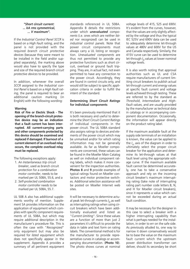
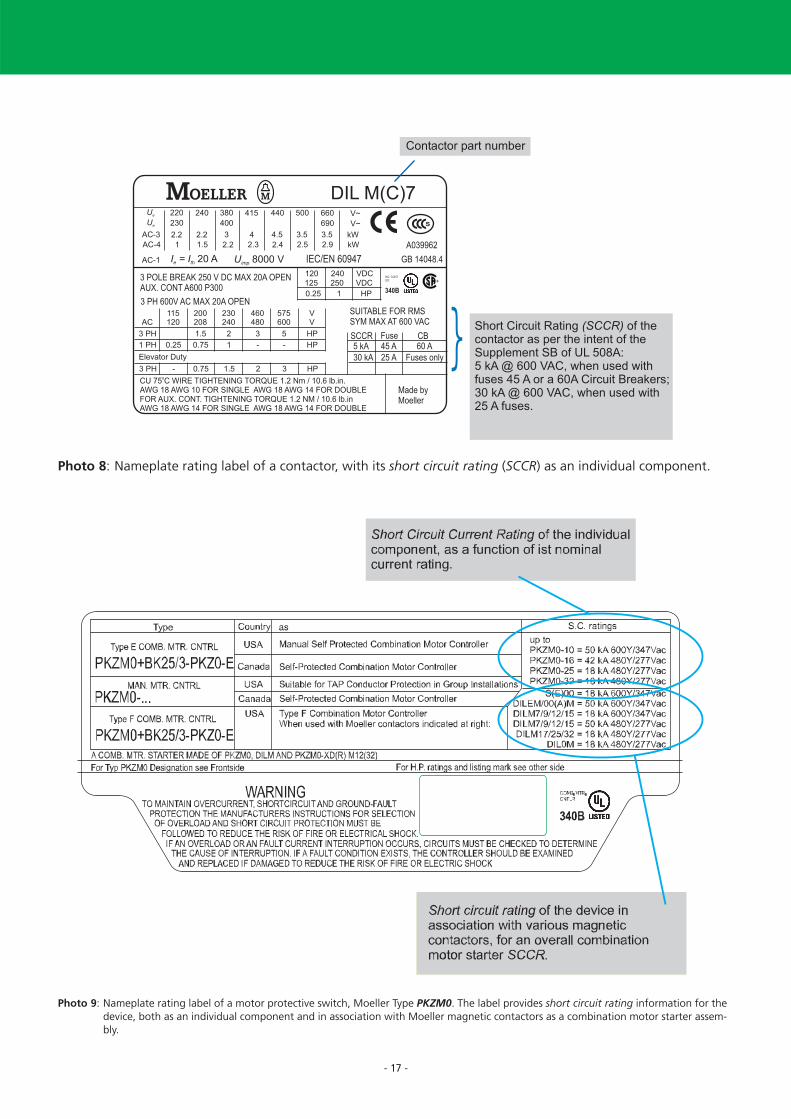
It's been previously mentioned that itis both necessary and useful to deter-mine the Short Circuit Current Ratingsof individual components in thepower circuit. The UL 508A standardalso assigns ratings to devices and ele-ments of the power circuit which maybe unmarked and/or for which ratinginformation may not be generallyavailable. As far as Moeller compo-nents are concerned, these values canbe found in the Moeller Main Catalogas well on individual component rat-ing labels, which makes it more con-venient for the inspection authorities.Photos 8 and 9 provide examples oftypical ratings found on Moeller con-tactors and motor protective switch-es. Additional selection assistance willbe posted on Moeller Internet websites.
It will be necessary to determine actu-al peak let-through currents ID as wellas interrupting ratings when using cir-cuit breakers which have been addi-tionally evaluated and listed as"Current Limiting". Since these valuesare a function of more than just 2parameters it's difficult to provide thedata in table and text form on ratinglabels. The conventional method is forthe manufacturer to provide repre-sentative curves in catalogs or accom-panying documentation. (Photo 10).The photo shows curves at nominal
voltage levels of 415, 525 and 690V.It's evident from the curves, however,that the values are only slightly affect-ed by the voltage and thus the typicalIEC 525V and 690V data can be usedto adequately determine let-throughvalues at 480V and 600V for the USand Canada respectively. Similarly, the415V curve can be used to determinelet-through ID values at lower nominalvoltage levels.
It is also worth noting that approvalauthorities such as UL and CSArequire manufacturers of current lim-iting circuit breakers to publish actuallet-through current and energy valuesat specific fault current and voltagelevels achieved through testing. Theseare referred to by the standard asThreshold, Intermediate and High-Fault values, and are usually providedby the manufacturer as technical datain catalogs or in accompanying com-ponent documentation. Occasionally,the information will appear directlyon the product rating label.
If the maximum available fault at thesupply side terminals of an installationis known, the value can be applied tothe Icc axis of the diagram in order toultimately select the proper circuitbreaker for the application and deter-mine its let-through values at thatfault level using the appropriate volt-age curve. If the maximum availablefault cannot be determined accurate-ly, one has to take a conservativeapproach and rely on the incomingcircuit breaker's maximum interrupt-ing rating (take note of interruptingrating part number code letters B, N,and H for Moeller circuit breakers),since it represents a value which can-not be exceeded during an actualfault condition.
It may be necessary for the designer inthis case to select a breaker with ahigher interrupting capability thanwhat is perhaps needed for the instal-lation, in order to err on the safe side.As previously alluded to, one way tonarrow it down conservatively wouldbe to base the value on the maximumfault current which the upstreampower distribution transformer candeliver, should its secondary be short
- 17 -
Photo 8: Nameplate rating label of a contactor, with its short circuit rating (SCCR) as an individual component.
Photo 9: Nameplate rating label of a motor protective switch, Moeller Type PKZM0. The label provides short circuit rating information for thedevice, both as an individual component and in association with Moeller magnetic contactors as a combination motor starter assem-bly.

- 18 -
Photo 10: Typical curve to assist in determining the peal let-through current values of a listed current limiting circuit breaker, Moeller TypeNZM 2 "H" (H = high interrupting rating). If we take as an example an available fault of 40kA rms sym (Icc) at the point of installa-tion, the peak let-through current at 480V for the breaker, at that level of fault, can be seen to be 19kA. All components andassemblies mounted downstream from the breaker would have to be rated at only 19 kA or better in order to take full advantageof the circuit breaker's current limiting rating.

- 19 -
circuited at the transformer terminals.The power rating of the transformer,along with the secondary voltage andthe transformer impedance rating,would provide enough information toyield a reasonably appropriate valueof available fault for the power circuitdownstream in this respect (see Table1).
The breaker's interrupting rating inthis case would equate to its ShortCircuit Current Rating. Plotting thisvalue on the Icc-Axis and intersectingit with the appropriate voltage curvewould provide the peak let-throughvalues on the left hand side verticalaxis.
How can one arrive at a more suitableOverall Short Circuit Current Ratingfor the control panel, given the mag-nitude of the available fault currentand potential peak let-through val-ues? One way to positively influencethe outcome in terms of achievingbetter ratings could be the deliberateoversizing of switching componentssuch as contactors, and/or optimiza-tion of the protective elements in thepower circuit. For example, use of acurrent limiting circuit breaker, asopposed to a non-protective SwitchDisconnector or Molded Case Switch,would provide immediate benefits inthis respect. The selected circuitbreaker's interrupting rating can alsoinfluence the overall outcome.
It was previously mentioned how indi-vidual component ratings are estab-lished and, in some cases, can beassigned from tables in standards.Component assemblies, on the otherhand, such as fuseless combinationmotor starters from Moeller, can gen-erally feature better overall ratingsthan what can be achieved individual-ly, simply through the positive effectof dynamic interaction between com-ponents during short circuit condi-tions. However, it is crucial that theseresults always be achieved and inde-pendently validated through actualtesting. Indeed, such third party certi-fication by recognized agencies is astrict requirement throughout theNorth American electrical system ofCodes and Standards.
Summary:
The recent enactment of NEC Article409, together with the latest SBSupplement of UL 508A, seem at firstglance, from both a domestic andexporting perspective, to have furthercomplicated the already challengingtask of properly applying electricalequipment in North America. Thispaper points out, however, that theprovision of short circuit ratings oncontrol panels is a not only a techni-cally worthwhile endeavor, but onewhich may ultimately pave the wayfor a smoother approval process onthe part of North American electricalinspection authorities. In the US, thenew NEC Article brings much neededclarity and focus to the requirementsof Industrial Control Panels, especiallythose which may not have been builtand listed to UL 508A. For the panelbuilder, compliance with the require-ments of the standard has meant acloser relationship and addeddependency on the supplier and man-ufacturer of electrical componentsand assemblies. In order to achievetimely and cost effective solutions itwill often be more advantageous topurchase the majority of parts fromthe same supplier. Finally, it is recom-mended to refrain from having toengineer each panel on an individual,customized basis. Rather, it is best, ifat all possible, to standardize on thefewest number of possible solutionswhich, in spite of some slight vari-ance, could still be fully accomplishedwithin a similar and more narrowlydefined component framework.
Through comprehensive and oftencomplex testing, Moeller providespanel builders with truly useful andhelpful results (e.g. Tables 5 and 6).for the most commonly encounteredcomponents and motor starter assem-blies. The overall UL ratings achievedthrough component combinationtesting are often much better thanthose established for individual com-ponents. A good example of a systemsolution involves component mount-ed motor starter busbar adaptersfrom Moeller, which are tested incombination with the bus systemsonto which they are fastened and
connected. [6].
The individual parts of such a systemdon't necessarily need to be pur-chased completely assembled fromMoeller. It's entirely permissible forthe panel builder to combine theparts on his own, provided he usesonly those listed parts described in themanufacturer's procedure and, ofcourse, doesn't exceed the overallassembly ratings as shown on respec-tive rating labels. Additional applica-tion stipulations appearing in themanufacturer's procedure in thisrespect would naturally also requirestrict adherence on the part of theinstaller. Whenever necessary, Moelleralso provides appropriate instructionsin catalogs and/or on the product'saccompanying documentation andset of installation instructions.
Because bus bar systems, construc-tionally speaking, are nearly alwayslocated in the more demanding feed-er circuit (Photo 11), they figure to bea particularly important point of con-sideration when discussing succesfulexport of electrical equipment toNorth America. Moeller providespanel builders and end-users in NorthAmerica, as well as exporting OEMcustomers from the IEC world, withpractical selection tables gearedtowards facilitating a more preciseand applicable determination of theSCCR (Short Circuit Current Rating)now required on the IndustrialControl Panel rating nameplate. Thepanel builder should only be installingpower circuit components with readi-ly identifiable and marked short cir-cuit current ratings, i.e. only thosewhich can be safely and reliably beincluded in the overall SCCR determi-nation.
It would be false to conclude that thisnew NEC Article affects only compo-nent manufacturers and panelbuilders, at the exclusion of all othersin the chain. On the contrary, futureend-users and/or buyers of electricalequipment alike should familiarizethemselves with these changes, ifanything, so that they may make bet-ter informed and more educated deci-sions on their purchases and invest-

Table 5: Short Circuit Rating of UL 508 Type F-Combination Motor Controllers mounted without bus bar adapters. The same ratings apply forMotor Starter Combinations Type MSC of similar HP ratings and featuring the innovative and time saving "toolless" plug wiring con-nectors. Also included are reversing combinations in those sizes, which have a set of mechanically and electrically interlocked contac-tors. (The mechanical interlock is always required for reversing starters in North America.)
UL 508 Type F Combination Motor Controllers
Can be applied without a contactor as a UL 508 Type E Self-Protected Combination Motor Controllers
Maximum HP Rating Setting Range Short Circuit Line side Motor Contac-3-phase, 60 Hz Current Rating terminal Protective tor
SCCR always Switch208 V 240 V 480V1) 600 V1) Adjustable Fixed 200 V 600 V1) required
(200 V) (230 V) (460 V) (575 V) Thermal Instantaneous 240 VTrip 480 V1)
HP HP HP HP A A kA kA Type Type Type
0,2 - 0,25 3,4 50 50 BK25/3- PKZM0-0,25 DILM7
0,3 - 0,4 5,6 50 50 PKZ0-E PKZM0-0,4 DILM7
0,4 - 0,63 8,8 50 50 PKZM0-0,63 DILM7
½ ½ 0,6 - 1 14 50 50 PKZM0-1 DILM7
¾ 1 1 - 1,6 22 50 50 PKZM0-1,6 DILM7
½ ½ 1 1½ 1,6 - 2,5 35 50 50 PKZM0-2,5 DILM7
1 1 2 3 2,5 - 4 56 50 50 PKZM0-4 DILM7
1½ 1½ 3 5 4 - 6 88 50 50 PKZM0-6,3 DILM7
3 3 7½ 10 6,3 - 11 140 50 50 PKZM0-10 DILM9
3 3 7½ - 8 - 12 168 50 50 PKZM0-12 DILM12
3 5 10 - 10 - 16 224 18 - PKZM0-16 DILM15
5 5 10 - 16 - 20 280 18 - PKZM0-20 DILM25
5 7½ 15 - 20 - 25 350 18 - PKZM0-25 DILM25
7½ 10 20 - 25 - 32 448 18 - PKZM0-32 DILM32
3 5 10 - 10 - 16 224 50 - BK50/3- PKZM4-16 DILM17
7½ 7½ 20 - 20 - 25 350 50 - PKZ4-E PKZM4-25 DILM25
10 10 25 - 25 - 32 448 50 - PKZM4-32 DILM32
10 10 30 - 32 - 40 560 50 - PKZM4-40 DILM40
1) Suitable for grounded 480 Y / 277 V 60 Hz and 600 Y / 347 V 60 Hz networks only.
- 20 -
ments. That's especially the case,given that these changes deal mostlywith the safety and dependability ofthe equipment over the entire life-span of the machine and its associat-ed electrical equipment. Price differ-ences from various manufacturersources can ultimately have a crucialbearing on the overall reliability ofthe installation. A thorough attemptto consider the complete life cycle ofthe equipment when weighing a pur-chase decision will nearly always yielda decision offering the best value inthe long run.
Validity:
The information provided in thispaper represents a thoroughly anddutifully researched interpretation bythe author of relevant portions of theNEC 2005 Code book and the UL508A standard, valid as of June 2006.It does not purport to serve as a sub-stitute for the informational contentof current and pertinent NorthAmerican standards, since moredetailed information for both domes-tic panel builders and exporters ofelectrical machines and equipmentdestined to North America would berequired for more comprehensive
design and engineering purposes. Incase of any doubt with respect to theproper interpretation of these norms,it is highly recommended to directlyconsult the assistance resources ofthese respective approval and stan-dard making agencies. The paperdoes not attempt to make commenton the standards themselves. Rather,the informational content serves tohighlight the compliance of Moellerproducts and assemblies with appro-priate and pertinent excerpts takenfrom the afore-mentioned NorthAmerican electrical standards.

- 21 -
Table 6: Short circuit rating of motor starter combinations mounted on bus bar adapters. The ratings apply for fully equipped adapters or forcustomer assembly using the identical parts and configurations. As per Table 5, reversing combinations are also possible in thosesizes, and always feature a set of mechanically and electrically interlocked contactors. (The mechanical interlock is always requiredfor reversing starters in North America.)
An upcoming table, which is planned to be posted as a link at the UL web site for short circuit rated industrial con-trol panels, will include references to the UL file, the starter ID numbers, minimum volume sizes per starter, therespective Conditions of Acceptability associated to each starter, the number of phases and HP ratings, the compo-nent abbreviation tags (e.g. CB, DS, F, MC etc...) as well as the type of combination starter it is per the UL nomen-clature (e.g. Types A, D, E, F etc....). The table is currently in preparation.
UL 508 Type F Combination Motor Controllers, complete sets mounted on bus bar adaptersShort Circuit Rating of combinations mounted on bus bar adapters.
Can be applied without a contactor as a UL 508 Type E Self-Protected Combination Motor Controllers
Maximum HP Rating Setting Range Short Circuit Starters mounted Incoming 3-phasig, 60 Hz Current Rating on busbar adapters terminal block,
SCCR always required 208 V 240 V 480V1) 600 V1) Adjustable Fixed 200 V 600 V1) (IEC-version, for UL versions
(200 V) (230 V) (460 V) (575 V) Thermal Instantaneous 240 V please note column Trip 480 V1) at right) Type:
HP HP HP HP A A kA kA Type BK25/3-PKZ0-E
0,2 - 0,25 3,4 50 50 MSC-D-0,25-M7(24VDC)/BBA
0,3 - 0,4 5,6 50 50 MSC-D-0,4-M7(24VDC)/BBA
0,4 - 0,63 8,8 50 50 MSC-D-0,63-M7(24VDC)/BBA
½ ½ 0,6 - 1 14 50 50 MSC-D-1-M7(24VDC)/BBA
¾ 1 1 - 1,6 22 50 50 MSC-D-1,6-M7(24VDC)/BBA
½ ½ 1 1½ 1,6 - 2,5 35 50 50 MSC-D-2,5-M7(24VDC)/BBA
1 1 2 3 2,5 - 4 56 50 50 MSC-D-4-M7(24VDC)/BBA
1½ 1½ 3 5 4 - 6,3 88 50 50 MSC-D-6,3-M7(24VDC)/BBA
3 3 7½ 10 6,3 - 11 140 50 50 MSC-D-10-M9(24VDC)/BBA
3 3 7½ - 8 - 12 168 50 50 MSC-D-12-M12(24VDC)/BBA
3 5 10 - 10 - 16 224 18 - MSC-D-16-M17(24VDC)/BBA
5 5 10 - 16 - 20 280 18 - MSC-D-20-M25(24VDC)/BBA
5 7½ 15 - 20 - 25 350 18 - MSC-D-25-M25(24VDC)/BBA
7½ 10 20 - 25 - 32 448 18 - MSC-D-32-M32(24VDC)/BBA
1) Suitable for grounded 480 Y / 277 V 60 Hz and 600 Y / 347 V 60 Hz networks only.

Protection Association, Inc.Quincy, Massachusetts 02169-7471
[4] UL 508A, "Standard for Industrial Control Panels, 2001, May 1, 2003Copyright: Underwriters Laboratories INC.
[5] Wolfgang Esser"Motorstarter und Special Purpose Ratings für den nord-amerikanischen Markt"Moeller GmbH, Bonn, 2006VER1200+2100-953DArticle No.: 106648
Wolfgang EsserMoeller GmbH, Bonn, 2006VER1200+2100-953GB Article No.: 106649
[6] Wolfgang Esser"Sammelschienenadapter für die rationelle Motorstarter-montage auch auf dem nord-amerikanischen Markt erfolg-reich einsetzen"Moeller GmbH, Bonn, 2006VER4300-960DDownload: http://www.moel-ler.net/binary/ver_techpapers/ver960de.pdf
Wolfgang Esser“Busbar Component Adapters - formodern industrial control panelassembly are now fully compliantwith North American marketrequirements”Moeller GmbH, Bonn, 2006VER4300-960GBDownload: http://www.moel-ler.net/binary/ver_techpapers/ver960en.pdf
Author: Dipl.-Ing. Wolfgang Esser Leiter ProduktsupportIndustrieschaltgeräteGeschäftsbereiche Leistungsschalter,Motorstarter und DrivesMoeller GmbH, Bonn
The essay has been produced with thekind support of:
Mr. BA Phys. Andre R. FortinManager - Codes & StandardsInternational Corporate Advisor –Power ProductsMoeller Electric Corporation, Millbury, Massachusetts, USAandMr. Dipl.-Ing. Dieter ReißInstitute for International Product Safety GmbH, Bonnand Mr. Dipl.-Ing. Dirk MeyerMoeller GmbH, Bonn
References:
[1] Wolfgang Esser"Besondere Bedingungen für den Einsatz von Motorschutz-schaltern und Motorstartern in Nordamerika"Moeller GmbH, Bonn, 2004VER1210-1280-928DArticle No.: 267951Download: http://www.moel-ler.net/binary/ver_techpapers/ver928de.pdf
Wolfgang Esser"Special considerations gover-ning the application of Manual Motor Controllers and Motor Starters in North America"Moeller GmbH, Bonn, 2004VER1210-1280-928GBArticle No.: 267952Download: http://www.moel-ler.net/binary/ver_techpapers/ver928en.pdf
[2] IEC / EN 60 204-1, DIN VDE 0113 Teil 1 "Sicherheit von Maschinen, Elektrische Aus-rüstung von Maschinen, Teil 1:Allgemeine Anforderungen" (IEC 204-1: 1997 + Corrigendum 1998)
[3] NEC 2005 HandbookNFPA 70: National Electrical Code 2005, National Fire
- 22 -
Photo 11: North American standards place a greater emphasis on maintaining adequate air and creepage clearances for components and cir-cuit elements located In the incoming supply circuit (Feeder Circuit). These requirements will impact construction aspects of devicessuch as bus bar systems and bus component adapters, which are often part of the feeder circuit.

www.moeller.net
Xtra Combinations
Xtra Combinations fromMoeller offers a range of products and services, enabling the best possiblecombination options for switching, protection andcontrol in power distributionand automation.
SCCR – Overall Panel Short
Circuit Current Rating
– per NEC and UL standards –
Technical PaperDipl-Ing. Wolfgang Esser
Moeller addresses worldwide:www.moeller.net/addressE-Mail: [email protected]
© 2007 by Moeller GmbHSubject to alterationsVER0211-959GB MDS/Schrems 01/07Printed in Austria (02/07)Article No.: 110102
Xtra Combinations
Xtra Combinations from Moeller offers a range of productsand services, enabling the best possible combination optionsfor switching, protection and control in power distributionand automation.
Using Xtra Combinations enables you to find more efficientsolutions for your tasks while optimising the economic viability of your machines and systems.
It provides:■ flexibility and simplicity■ great system availability■ the highest level of safety
All the products can be easily combined with one another mechanically, electrically and digitally, enabling you to arriveat flexible and stylish solutions tailored to your application –quickly, efficiently and cost-effectively. The products are proven and of such excellent quality thatthey ensure a high level of operational continuity, allowingyou to achieve optimum safety for your personnel, machinery,installations and buildings.
Thanks to our state-of-the-art logistics operation, our com-prehensive dealer network and our highly motivated servicepersonnel in 80 countries around the world, you can count on Moeller and our products every time. Challenge us! We are looking forward to it!
VER0211-959_D_GB 27.02.2007 13:15 Uhr Seite U4