scattering contrast - trinity college, dublin · scattering contrast dr. hongzhou zhang ... 0.1-0.2...
TRANSCRIPT


Lecture 5
• Dynamical contrast: Characteristic Images of Perfect Crystals (perfect crystal, annealed, single phase)
• Thickness fringes
• Bend contours

TEM Contrast
• Scattering/Amplitude Contrast – BF/DF: thickness, tilt – Low-medium magnification – Applications
• Crystal defects: dislocations, stacking faults, phase boundaries, precipitates, defect clusters
• Contrast: g, type of the fault, its depth in the crystal
• Quantitative determination of b • Resolution: strongly excited: 10 nm; weak beam:
1nm
• Phase Contrast: – High magnification – Highly coherent beam – Large defocusing – Resolution: 0.1-0.2 nm – Reliable interpretation: Simulation
What is contrast?
11
12
I
I
I
IIC
Difference in intensity between two adjacent areas
•Eyes: < 5% - can’t detect <10% - difficult
•Enhance digital image electronically

Mass-thickness Contrast • The diaphragm
– the focal plane of the objective lens – Limiting angle : Transmission T()
• Absorbs scattered electrons > 0
• T() – The objective aperture 0
– The electron energy E – The mass thickness x=t – The material composition:
» Atomic weight, A » Atomic number Z
• The illumination aperture < 0 (TEM)
• Samples – Amorphous
• Incoherent scattering? Diffuse maxima
– Surface replica – Biological sections – Polycrystalline films with very small
crystals xfZh
mef
2
2
2
0 sin24
1

Mass-Thickness: an Example Latex particles on a carbon support film
Thickness-contrast
Diffraction Contrast
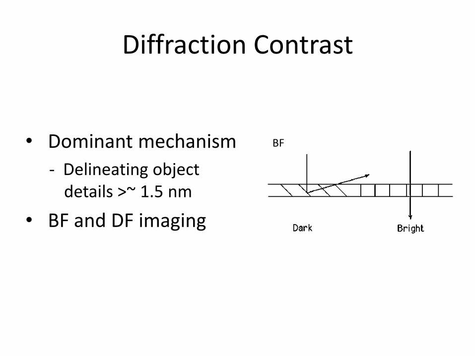
• Dominant mechanism
- Delineating object details >~ 1.5 nm
• BF and DF imaging
BF

Atomic Model of Dislocations
An Edge dislocation
A screw dislocation
Burgers Vectors
Dislocation line
Strain field ~ distortion of the lattice

Low Angle Grain Boundry
•A low angle tilt boundary in Ge. •Spacing of dislocations in the boundary is inversely proportional to the angle of mis-orientation. •D=b/

Relevance of Diffraction Theory to Studies of Crystal Defects
• Equivalent form of the dynamical diffraction theory – Plane waves: Darwin-Howie-Whelan equations – Block waves – Modified Block waves – slowly varying strain field – Scattering Matrix – Planar defect/precipitates
• Defects – Locally varying strain field (dislocation, misfitting precipitates, etc. ) – Planar defect(stacking faults, interfaces) – Void/gas bubbles
• Important parameters – The reflecting plane vector: g – The deviation from the Bragg position: s – The extinction distance: g ~ (g ) – Deviation from the Bragg position: w = gs – The anomalous absorption coefficient (ANO= g / ’g )
• Depends on g • Stacking faults sensitive to ANO … determine ANO

Bright Field and Dark Field Images
•Maps of the intensity distribution across the T/D beams •Point-to-point efficiency of diffraction process •The atomic planes near a dislocation core are strained and hence the diffraction conditions surrounding a dislocation are different. •Resolution of DF images are usually better than BF images.

Bright Field Images
• Thin film BF images showing two parallel rows of edge dislocations.
• Thickness of the film is ≈ 200 nm.
• The photograph above is a projected image of the dislocation lines which are illustrated in the line image.
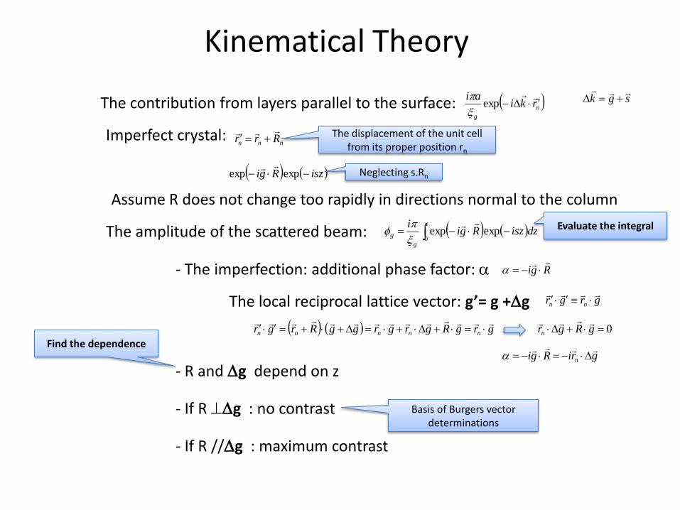
Kinematical Theory
The contribution from layers parallel to the surface: n
g
rkiai
exp
Imperfect crystal: nnn Rrr
The displacement of the unit cell
from its proper position rn
sgk
iszRgi expexp
Neglecting s.Rn
Assume R does not change too rapidly in directions normal to the column
The amplitude of the scattered beam: t
g
g dziszRgii
0expexp
- The imperfection: additional phase factor: Rgi
The local reciprocal lattice vector: g’= g +g grgr nn
grgRgrgrggRrgr nnnnn
0 gRgrn
griRgi n
- R and g depend on z
Evaluate the integral
Find the dependence
- If R g : no contrast Basis of Burgers vector determinations
- If R //g : maximum contrast

Single Screw Dislocation: Elastically isotropic
• Elastically isotropic material: – W, Al, Zn, Mg, Ti, MC –
• Dislocation image: g.b – A perfect dislocation g.b = 0 or N – A partial dislocation g.b = 0, fraction, or N
• BF: – A dark line: g.b = 1,2, … etc. – Complicated: g.b = fractions – g.b = 0 Invisibility criterion:
• To get b • Diffracting planes contain b – not distorted
– g.b 0 • Undistorted: +; s>0 → BF brighter • Distorted: s = 0 → strongly diffracted, BF darker
g
g
g
g
g
iRgiisz
i
dz
d
Rgiiszii
dz
d
exp
exp
0
0
0
0
0
2
bR

Quantitative analysis: Dislocations
• Quantitative analysis: Crystal defects – Image characteristics of crystal
defects – Procedures for
indentifying/obtaining quantitative information • Determine the direction of b • Computer matching:
the magnitude and sense of b • Solve equations:
– Dislocation line direction: u – The Burgers vector: b – Orientation within the thin foil – The elastic anisotropy of the material
– Dynamical conditions
`The same region of an aluminium foil with different operative reflections
(020) (200)
(11-1)
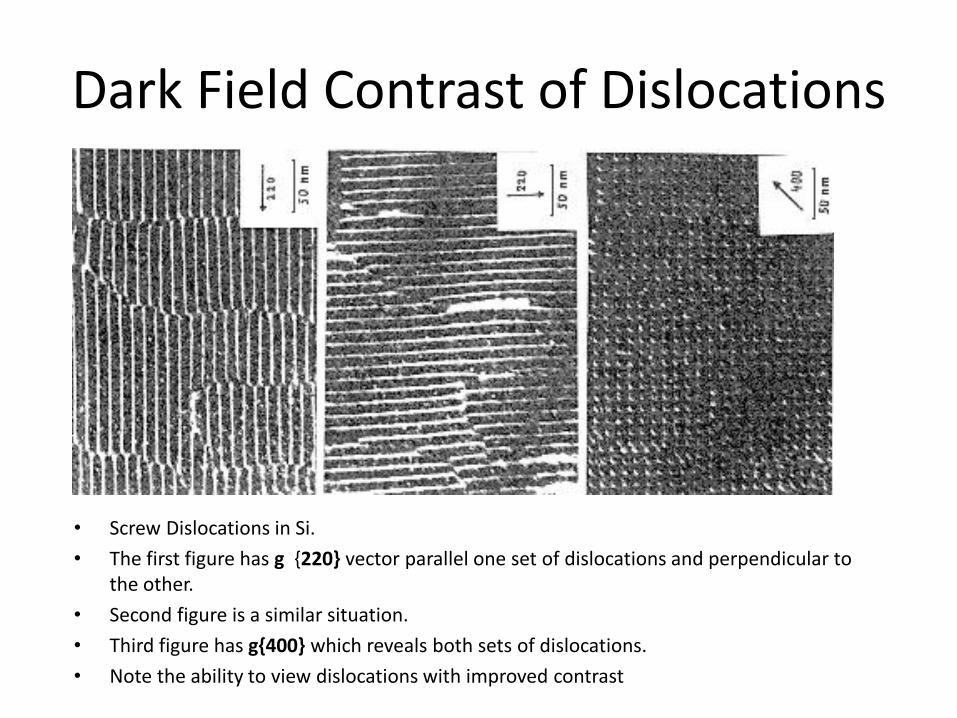
Dark Field Contrast of Dislocations
• Screw Dislocations in Si.
• The first figure has g {220} vector parallel one set of dislocations and perpendicular to the other.
• Second figure is a similar situation.
• Third figure has g{400} which reveals both sets of dislocations.
• Note the ability to view dislocations with improved contrast

Complex Dislocation Tangles
• A crack in Si (Dark line) emits a number of dislocations on thermal cycling.
• The dislocations were formed to relieve thermal stresses.

Imaging Techniques (TEM)
• First set is a comparison of DF image and a Weak Beam Image.
• Second set is a comparison between a Weak beam image and a BF image.
• The WB technique is a higher resolution form of DF imaging and is primarily used for imaging closely spaced defect structures on the nanometer scale
• Note that in the WB image the contrast and resolution is better than corresponding BF or DF images.

Experimental Conditions for Quantitative Analysis
• Two-beam conditions • BF
– s>0 and small (bright Kikuchi line just outside diffraction spot) – w=gs ~ 0.1-1.0
• DF: w ~ ±1.0
• Avoid thin areas (< 2-3g): rearrangement of defects • Avoid regions of rapidly changing thickness: thickness
fringes • Suitable thickness: 5-8*g
• Penetration depends on reflection – Hcp: {2-200} better than {1-100} – Poor penetration:
• Systematically absent reflections appear due to double diffraction • Ordered materials, superlattice reflections
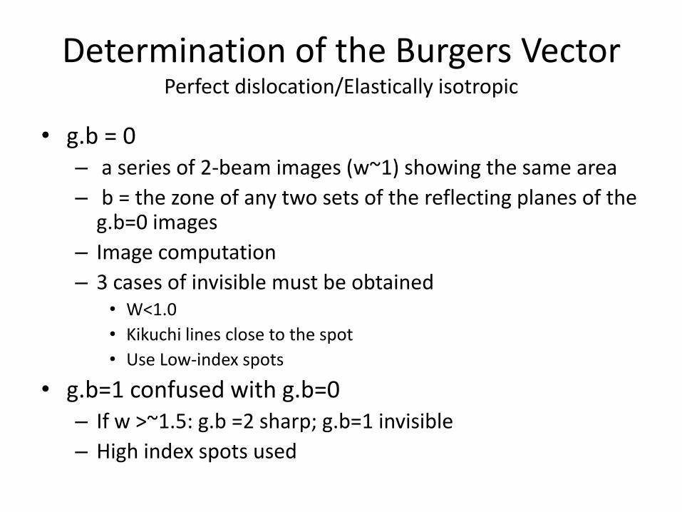
Determination of the Burgers Vector Perfect dislocation/Elastically isotropic
• g.b = 0 – a series of 2-beam images (w~1) showing the same area
– b = the zone of any two sets of the reflecting planes of the g.b=0 images
– Image computation
– 3 cases of invisible must be obtained • W<1.0
• Kikuchi lines close to the spot
• Use Low-index spots
• g.b=1 confused with g.b=0 – If w >~1.5: g.b =2 sharp; g.b=1 invisible
– High index spots used

Determination of the Burgers Vector Perfect dislocation/Elastically anisotropic
• g.b = 0 inappliable – g.b=0, considerable contrast occurs – Image matching must be used
• Computer simulation: – different operative diffractions – Guess a b
• Enables: magnitude + direction
• Calculation shows – considerably modification of the previous discussion – Different form of displacement field – distort the diffracting planes – Impossible to obtain well-defined invisibility – Complicates the determination of b
• Pseudo-isotropically – Cubic (pure edge or screw {110} or{100}) – Hexagonal (basal and planes basal)
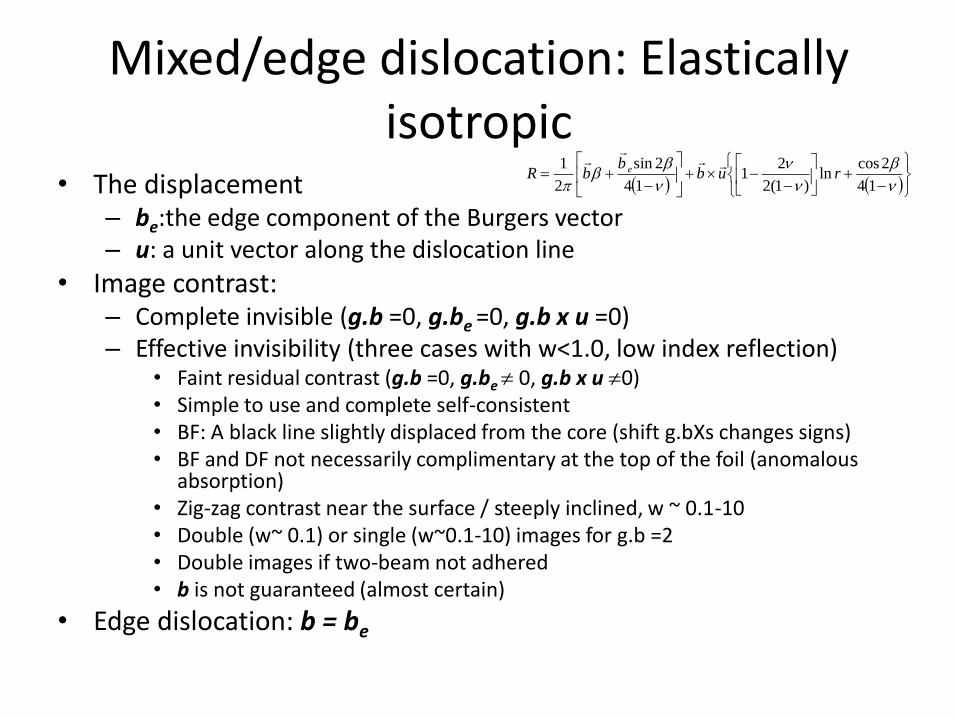
Mixed/edge dislocation: Elastically isotropic
• The displacement – be:the edge component of the Burgers vector – u: a unit vector along the dislocation line
• Image contrast: – Complete invisible (g.b =0, g.be =0, g.b x u =0) – Effective invisibility (three cases with w<1.0, low index reflection)
• Faint residual contrast (g.b =0, g.be 0, g.b x u 0) • Simple to use and complete self-consistent • BF: A black line slightly displaced from the core (shift g.bXs changes signs) • BF and DF not necessarily complimentary at the top of the foil (anomalous
absorption) • Zig-zag contrast near the surface / steeply inclined, w ~ 0.1-10 • Double (w~ 0.1) or single (w~0.1-10) images for g.b =2 • Double images if two-beam not adhered • b is not guaranteed (almost certain)
• Edge dislocation: b = be
14
2cosln
)1(2
21
14
2sin
2
1rub
bbR e

Lecture 6
• Phase contrast and HRTEM