scanning radiometer for measurement of · pdf filescanning radiometer for measurement of...
TRANSCRIPT

NASA TECHNICAL
MEMORANDUM
CO
NASA TM X-3454
,.~ -.> r-~_
FH )gM t-lF >f( t %*J•* wtia R-,3
SCANNING RADIOMETER FOR MEASUREMENTOF FORWARD-SCATTERED LIGHTTO DETERMINE MEAN DIAMETER
OF SPRAY PARTICLES
Donald R. Buchele
Lewis Research Center
Cleveland, Ohio 44135
NATIONAL A E R O N A U T I C S AND SPACE ADMINISTRATION • WASHINGTON, 0. C. • NOVEMBER 1976
https://ntrs.nasa.gov/search.jsp?R=19770004423 2018-05-09T17:13:11+00:00Z

1. Report No.
NASA TMX-34542. Government Accession No. 3. Recipient's Catalog No.
4. Title and Subtitle SCANNING RADIOMETER FOR MEASUREMENTOF FORWARD-SCATTERED LIGHT TO DETERMINEMEAN DIAMETER OF SPRAY PARTICLES
5. Report Date
November 19766. Performing Organization Code
7. Author(s)
Donald R. Buchele8. Performing Organization Report No.
E-8816
9. Performing Organization Name and Address
Lewis Research CenterNational Aeronautics and Space AdministrationCleveland, Ohio 44135
10. Work Unit No.
505-0411. Contract or Grant No.
12. Sponsoring Agency Name and Address
National Aeronautics and Space AdministrationWashington, D.C. 20546
13. Type of Report and Period Covered
Technical Memorandum14. Sponsoring Agency Code
15. Supplementary Notes
16. Abstract
A scanning radiometer was built that measures forward-scattered light to determine the meandiameter of spray particles. An optical scanning method gives a continuous measurement ofthe light-scattering angle during spray nozzle tests. A method of calibration and a correctionfor background light are presented. Mean particle diameters of 10 to 500 micrometers canbe measured.
17. Key Words (Suggested by Author(s))
Particle size determinationLight scattering metersOptical scanners
18. Distribution Statement
Unclassified - unlimitedSTAR Category 35
19. Security Classif. (of this report)
Unclassified20. Security Classif. (of this page)
Unclassified21. No. of Pages
1722. Price"
$3.50
* For sale by the National Technical Information Service, Springfield. Virginia 22161
SCANNING RADIOMETER FOR MEASUREMENT OF FORWARD-SCATTERED
LIGHT TO DETERMINE MEAN DIAMETCR OF SPRAY PARTICLES
by Donald R. Buchele
Lewis Research Center
SUMMARY
One of the factors that can have a significant effect on both the performance and thepollutant emission characteristics of gas turbine combustors is the dispersion of fuelparticles from the fuel nozzle. Consequently, to determine the mean diameter of sprayparticles, a scanning radiometer was built that measures forward-scattered light fromspray particles. An optical scanning method gives a continuous measurement of thelight-scattering angle during spray nozzle tests. A method of calibration and a correc-tion for background light are presented. Mean particle diameters of 10 to 500 microm-eters can be measured.
INTRODUCTION
This report describes the design of a scanning radiometer that was built for thecontinuous, real-time measurement of the mean diameter of liquid particles in a spray.The dispersion of fuel particles from the fuel nozzle is one of the factors that can havea significant effect on both the performance and the pollutant emission characteristicsof gas turbine combustors. The effectiveness of various fuel nozzle designs has beendetermined in the past by direct observations and photographs of fuel or water spraypatterns as well as by measurement of combustor performance.
Liquid particle diameter in the spray from a fuel nozzle can be inferred from dif-fractively scattered light for particle diameters greater than the wavelength of light. Anoptical system for the measurement of radiant flux at any small angle of forward scat-tering is described in references 1 and 2. Reference 1 gives a mathematical descriptionof the scattering properties of a polydispersion of particles, and reference 2 shows theeffects of different particle-diameter distributions on the light-scattering irradiancedistribution. It was found that the irradiance distribution is only weakly related to the

particle-diameter distribution. The irradiance distribution can be used to determinethe Sauter mean particle diameter, which is defined as the ratio of total particle volumeto total particle surface area of all particles surveyed. The Sauter mean diameter wasfound to be less sensitive to particle-diameter distribution than were other geometricquantities of the spray particles, such as the arithmetic mean diameter and the meandiameter based on the ratio of the total surface area to the total diameter of the dropsin the spray.
In developing fuel spray nozzles for gas turbine combustors, one experimentalmethod is to test the nozzles with water in an air stream. These test results can char-acterize the spray by the Sauter mean diameter. Subsequent operating tests with fuelin a combustor determine the combustor performance and the pollutant emission concen-trations that are related to the Sauter mean diameter. To minimize the duration of thistype of test program, the scanning radiometer was designed for continuous real-timemeasurement.
INSTRUMENT DESIGN
Light- Scattering Equations
An optical system described in references 1 and 2 for measurement of the radiantflux at any small angle of forward scattering is shown in figure 1. Light from a pointsource is collimated by lens A, passes through test section B, and is focused to a pointby lens C. It can be shown that light scattered anywhere in the test section at an angle9 intersects the focal plane D at a distance y from the focal point. Thus,
e=z (D
for y/f « 1, where f is the lens focal length. (Symbols are defined in the appendix. )Reference 2 shows that one irradiance distribution function closely approximates
actual irradiance distributions for a variety of particle-diameter distributions providedthat no particles exist with a diameter larger than approximately 10 times the meandiameter of the particles. This irradiance distribution H(P) for a polydiameter sprayis shown in figure 2, where the abscissa that relates the measured beam-spread angle9 to the Sauter mean particle diameter Dg2 is
(2)

where A is the wavelength of the source light and Dgg > *•• Since the distributionfunction H(P) is known, measurement of angle 0 at a preset value of H, say 0.3 to0.5, determines P from figure 2, and Dg2 is then calculated by equation (2).
The instrument described in this report continuously measures 6 by using theoptical system of figure 1 and a scanning method to be described. A method of calibra-tion and a correction for background light are presented. This instrument was designedto measure the mean particle diameter in accordance with the mean irradiance distribu-tion curve developed in reference 2. If a diameter distribution is desired, a differentoptical scanner and different data-gather ing electronics would be required. The designof this new equipment would depend on the analytical method used to compute the diam-eter distribution with acceptable accuracy from the measurements.
Description of Instrument
The optical system, with dimensions, is shown in figure 3(a). A 1-milliwatt helium-neon (He-Ne) laser with a condensing lens forms a point source of light. An aperture0. 003 centimeter in diameter intercepts stray radiation outside the point source. Acollimating lens with a 7.5-centimeter-diameter aperture is smaller than the 10. 0-centimeter-diameter converging lens to allow for beam spread up to 0. 025 radian fromscattering at the test section. A 5-centimeter-diameter lens collects all scattered lightthat passes through a slit on the scanning disk and focuses it on the scanning detector.This lens images the test section on the detector. Figure 3(b) shows the scanning diskwith the scanning slit and a second slit with a timing detector at a larger radius to pro-vide a timing pulse for signal conditioning. The disk rotates at 1800 rpm.
The electronic measurement circuit in figure 4(a) has signal waveforms, shown infigure 4(b), for a time spanning 1 revolution of the scanning disk. The peak of thescanner signal (1) is detected and held by the peak detector until the peak is reset tozero. The timing pulse resets the peak detector (2), thus producing the output (3) witha new peak following each scan. At the input of the comparator (4), the scanner signal(1) and a low-pass filtered fraction of peak voltage (3) as determined by the attenuatorsetting are compared. The fraction of voltage (3) is adjustable from 0.8 to 0. 05.Whenever signal (1) is greater than signal (4), the detector output (5) is 4 volts; other-wise, it is zero. This pulse width w is the width of the scanner waveform at the presetfraction of its peak amplitude. This pulse waveform is bandpass filtered, and the am-plitude of the alternating-current component at (6) is proportional to the pulse width forsmall ratios of pulse width w to pulse period W. The voltage at (6) is measured by ameter that can be calibrated to read Don directly.

Principle of Scanning Slit
With no spray in the test section the irradiance distribution is that of the image ofthe source. This is illustrated in figure 5(a). This distribution can be no narrowerthan the Airy diffraction distribution for an ideal lens with a point source. The distribu-tion width is further increased by the finite size of the point source of radiation, thelens aberrations, and some scattering from lens surface dirt. Spray in the test sectionscatters some of the light, with a distribution illustrated in figure 5(b).
When the spray is not dense, a large part of the radiation is not scattered by thespray. This light has the same irradiance distribution as existed before the spray waspresent, but of lower amplitude. Figure 5(c) is the sum of a reduced amplitude of 5(a),caused by scattering, plus the scattered radiation of 5(b). The measurement problem isto obtain 5(b) from measurements of 5 (a) and 5(c).
The method used in the scanner is to intercept the major part of 5 (a) with a stop atthe, axial image point of the source at plane D in figure 1. The stop size is sufficient toreduce the amplitude to 0. 01 of the peak. This distribution is shown in figure 5(d). Thedepressed center of the curve is avoided by the design of the scanning slit (fig. 6(a)).The slit, of length A-A, is placed in an opaque rotating disk and is oriented in a radialdirection. The center of the slit is covered over a length B-B to make the stop. Everypoint on the slit scans an off-center section of the axisymmetric irradiance distribution.These sections, such as A and B in figure 6(b), do not have a depressed center. Eachof these sections has the same function, differing in relative amplitude, since the axi-symmetric irradiance distribution can be accurately approximated by a Gaussian distri-bution and since the arc of the scanning path, because of the large radius of the scanningdisk, approximates a straight line. To prove this, assume an axisymmetric Gaussiandistribution of irradiance about the optical axis at C given by
Any off-axis section parallel to the y-axis has the same function of y multiplied by aconstant that depends on x. The same result holds for a summation over any intervalAx. The Gaussian curve plotted in figure 2 closely approximates the polydiameter spraycurve for amplitudes greater than 0. 08 and P < 2. 7. Photoelectric conversion of theflux transmitted by the scanning slit gives a curve that can be displayed on an oscillo-scope for monitoring purposes.

ANALYSIS OF MEASUREMENT
Calibration
A calibration giving the mean particle diameter D32 in terms of the output voltagev from the circuit in figure 4(a) is preferably done with test cells containing known-diameter latex spheres suspended in liquid. An alternative when test cells are notavailable is an indirect calibration. It requires an oscilloscope and a light-scatteringmaterial such as particles of silicon carbide (SiC) or aluminum oxide (ALgOq) grit sup-ported between two flat windows. These particles produce light scattering similar tothat from spray particles, but the scattered light does not fluctuate like that from aspray. The waveform (5) in figure 4(b) is displayed on the oscilloscope, and a ratio(w/W)j of the pulse width to the pulse period is measured. (The subscript 1 denotescalibration.) The alternating-current voltage Vj at (6) in figure 4(a) is also measured.This voltage Vj is proportional to the ratio (w/W)j. Subsequent measurement of vduring a test with spray determines w/W as
(3)
The ratio w/W during a test is related to the distances traveled by the scanningslit as the scanner rotates. As shown in figure 4(b), waveform (4), the period W isproportional to the scanning path circumference 2irR. The width w is proportional tothe beam-spread width 2y that depends on the setting of the attenuator. Thus,
w_ 2y
W 2;rR(4)
Combining equations (1), (3), and (4) yields the measured beam-spread angle
6 = (5)
where the quantity in brackets is a calibration constant. The mean spray particle diam-eter D,2 is then given in terms of the measurement voltage v by substituting equa-tion (5) into equation (2) to obtain
D =-Pv
(6)
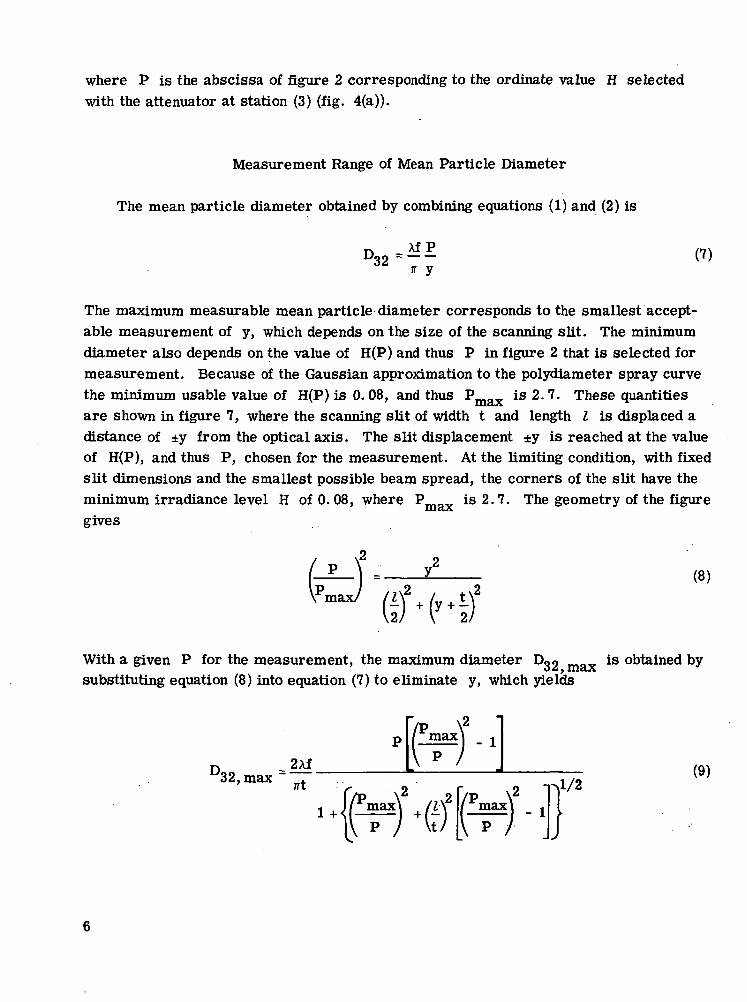
where P is the abscissa of figure 2 corresponding to the ordinate value H selectedwith the attenuator at station (3) (fig. 4(a)).
Measurement Range of Mean Particle Diameter
The mean particle diameter obtained by combining equations (1) and (2) is
no32p
y(7)
The maximum measurable mean particle diameter corresponds to the smallest accept-able measurement of y, which depends on the size of the scanning slit. The minimumdiameter also depends on the value of H(P) and thus P in figure 2 that is selected formeasurement. Because of the Gaussian approximation to the polydiameter spray curvethe minimum usable value of H(P) is 0.08, and thus Pmax is 2.7. These quantitiesare shown in figure 7, where the scanning slit of width t and length I is displaced adistance of ±y from the optical axis. The slit displacement ±y is reached at the valueof H(P), and thus P, chosen for the measurement. At the limiting condition, with fixedslit dimensions and the smallest possible beam spread, the corners of the slit have theminimum irradiance level H of 0.08, where ?_,_„ is 2.7. The geometry of the figuregives
(8)
With a given P for the measurement, the maximum diameter Dno max is obtained bysubstituting equation (8) into equation (7) to eliminate y, which yields
D,32, max _.
/*max
\
max
IV p /\2El *{*©
max - 1
a/2 (9)
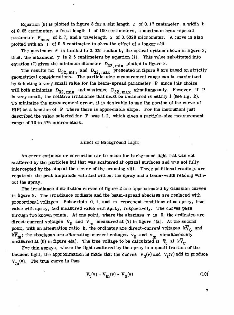
Equation (9) is plotted in figure 8 for a slit length I of 0.17 centimeter, a width tof 0. 05 centimeter, a focal length f of 100 centimeters, a maximum beam-spreadparameter Pmax of 2.7, and a wavelength A of 0. 6328 micrometer. A curve is alsoplotted with an I of 0.5 centimeter to show the effect of a longer slit.
The maximum 9 is limited to 0. 025 radian by the optical system shown in figure 3;thus, the maximum y is 2.5 centimeters by equation (1). This value substituted intoequation (7) gives the minimum diameter Dg2 mjn plotted in figure 8.
The results for Dg2 mjn and Dg2 max presented in figure 8 are based on strictlygeometrical considerations. The particle-size measurement range can be maximizedby selecting a very small value for the beam-spread parameter P since this choicewill both minimize Dg2 mjn and maximize Dgg max simultaneously. However, if Pis very small, the relative irradiance that must be measured is nearly 1 (see fig. 2).To minimize the measurement error, it is desirable to use the portion of the curve ofH(P) as a function of P where there is appreciable slope. For the instrument justdescribed the value selected for P was 1.2, which gives a particle-size measurementrange of 10 to 475 micrometers.
Effect of Background Light
An error estimate or correction can be made for background light that was notscattered by the particles but that was scattered at optical surfaces and was not fullyintercepted by the stop at the center of the scanning slit. Three additional readings arerequired: the peaK amplitude with and without the spray and a beam-width reading with-out the spray.
The irradiance distribution curves of figure 2 are approximated by Gaussian curvesin figure 9. The irradiance ordinate and the beam-spread abscissa are replaced withproportional voltages. Subscripts 0, t, and m represent conditions of no spray, truevalue with spray, and measured value with spray, respectively. The curves passthrough two known points. At one point, where the abscissa v is 0, the ordinates aredirect-current voltages VQ and Vm measured at (7) in figure 4(a). At the secondpoint, with an attenuation ratio k, the ordinates are direct-current voltages kVg andkV ; the abscissas are alternating-current voltages VQ and v simultaneouslymeasured at (6) in figure 4(a). The true voltage to be calculated is vt at kVt>
For thin sprays, where the light scattered by the spray is a small fraction of theincident light, the approximation is made that the curves VQ(V) and Vt(v) add to produceVm(v). The true curve is thus
= Vm(v) - V0(v)

and at v = 0,
Each curve has an equation
(11)
V(v)=Ve(v/?) lnk (12)
Solving equations (10) to (12) for vt and letting v = vm give
-2vt =
v2 Inm
r (vV m k -V r
V m -
k
/vj2 In k~|n
V°
for Vm > V0 (13)
This corrected voltage can be used with equation (6) during data analysis to correctDQO following real-time measurements that neglect the correction.
O£t
CONCLUDING REMARKS
Tests with the radiometer using water spray have shown that it is important to pro-tect the optical surfaces from the deposits that unconfined spray can produce. It is alsodesirable to minimize placing objects such as nozzles or instrumentation in the testsection, where their edge diffraction can increase the amount of background light addedto the measurement. Mean diameters of 75 to 150 micrometers have been recorded.Rapid changes of test conditions were possible by using real-time measurement.
Lewis Research Center,National Aeronautics and Space Administration,
Cleveland, Ohio, July 2, 1976,505-04.

APPENDIX - SYMBOLS
Doo Sauter mean diameter of particles
f focal length of objective lens (fig. 1)
H irradiance at plane of scanning disk (fig. 3) at focal length f (fig. 1)
k voltage attenuation factor (fig. 4)
I overall slit length
P beam-spread parameter (eq. (2), fig. 2)
R rotational radius of scanning slit
t -slit width
V voltage output of scanning detector
V peak value of V
v voltage proportional to beam-spread angle
v value of v with attenuation factor k times voltage V
W pulse period of oscilloscope trace (fig. 4)
w pulse width of oscilloscope trace (fig. 4)
y ray displacement at focal length f (fig. 1)
6 ray deviation angle at focal length f (measured beam-spread angle) (fig. 1)
A wavelength of source radiation
Subscripts:
m measured value with spray
t true value with spray
0 condition of no spray

REFERENCES
1. Chin, J. H.; Sliepcevich, C. M.; and Tribus, M.: Particle Size Distributions fromAngular Variation of Intensity of Forward-Scattered Light at Very Small Angles.J. Phys. Chem., vol. 59, Sept. 1955, pp. 841-844.
2. Dobbins, R. A.; Crocco, L.; and Classman, I.: Measurement of Mean ParticleSizes of Sprays from Diffractively Scattered Light. AIAA J., vol. 1, no. 8, Aug.1963, pp. 1882-1886.
10

Source
Figure 1. - Optical system
.1
t .01
.001
Polydiameterspray (ref. 2)
Gaussiandistribution
. fitted to poly-diameter spraycurve
2 4Beam-spread parameter,
Figure 2. - Irradiance distribution for meanparticle diameter 032, source radiation wave-length A, and beam-spread angle 6.
11

• 0.003 diamMultiplierphototube
Timing
0.05
Timingx detector
(a) Optical path.
/- Scanning slit
(b) Scanning disk.
Figure 3. - Details of optical system. (Dimensions are in cm.)
12

Timer
Oscilloscope testpoint, w/W
/- AttenuatorScanner waveformpeak amplitude V, dc
7
Scanner waveformwidth, v, ac
(a) Electronic circuit.
(1) Scanner
(2) Timer
(3) Peak detection
(4) Attenuated, filteredpeak and scanner output
(5) Zero crossing comparator
(6) Filtered ac component
(7) Filtered dc component
LA_n_ n
—i^ ir—0 \ Ja ^U a(2^R) J r Attenuated peak
±3T /U--L_n
Scanner
v, ac
V, dc
r*— 1 Revolution of —"-i1 scanning disk '
(b) Signal waveforms on oscilloscope.
Figure 4. - Signal conditioning.
13

(a) Instrument only. (b) Spray only. (c) Both instrumentand spray.
(d) Stop added to (c).
Figure 5. - Irradiance distributions.
Image of point sourceon optical axis, C
(a) SI it with center stop.
Irradiance
(b) Irradiance along scanpaths A, B, C.
Figure 6.: Scanning disk with slit.
14

j- Image of point sourceI on optical axis
^-""R^"^ 1
t /1 /
\
•^2-~t
'V
i -
^ 7
' /- Maximum beam-spread parameter/ / at irradiance of 0.08I // / /- Beam-spread parameter at/ <^ / measured irradiance
/ / \ ^Limiting slit position
S^^
1/
''%%,
^^^
'
\ ' »
' i1 / 1-y
/
^^ Limiting slit position
Figure 7. - Scanning slit with irradiance contours about optical axis.
15

251—
•s
raE
500
400
300
200
100
max.; I - 0.17cm
.4 .8 -. 1.2 1.6Beam-spread parameter, P
2.0 £4
Figures. - Maximum and minimum mean particle diameters. Slitwidth, t,0.05cm; focal length, f, 100cm; maximum beam-spread parameter, Pmax,2.7; wavelength, X, 0.6328 M m.
3 _ *Vm
V0 vmVoltage proportional to beam-spread angle, v
Figure 9. - Correction for background light.
16 NASA-Langley, 1976 E-8816

NATIONAL AERONAUTICS AND SPACE ADMINISTRATION
WASHINGTON, D.C. 2O546
OFFICIAL BUSINESS
PENALTY FOR PRIVATE USE S3OO SPECIAL FOURTH-CLASS RATEBOOK
POSTAGE AND FEES PAIDNATIONAL AERONAUTICS AND
SPACE ADMINISTRATION
1SI
POSTMASTER : If Undeliverable (Section 158Postal Manual) Do Not Return
"The aeronautical and space activities of the United States shall beconducted so as to contribute . . . to the expansion of human knowl-edge of phenomena in the atmosphere and space. The Administrationshall provide for the widest practicable and appropriate disseminationof information concerning its activities and the results thereof."
—NATIONAL AERONAUTICS AND SPACE ACT OF 1958
NASA SCIENTIFIC AND TECHNICAL PUBLICATIONSTECHNICAL REPORTS: Scientific andtechnical information considered important,complete, and a lasting contribution to existingknowledge.
TECHNICAL NOTES: Information less broadin scope but nevertheless of importance as acontribution to existing knowledge.
TECHNICAL MEMORANDUMS:Information receiving limited distributionbecause of preliminary data, security classifica-tion, or other reasons. Also includes conferenceproceedings with either limited or unlimiteddistribution.
CONTRACTOR REPORTS: Scientific andtechnical information generated under a NASAcontract or grant and considered an importantcontribution to existing knowledge.
TECHNICAL TRANSLATIONS: Informationpublished in a foreign language consideredto merit NASA distribution in English.
SPECIAL PUBLICATIONS: Informationderived from or of value to NASA activities.Publications include final reports of majorprojects, monographs, data compilations,handbooks, sourcebooks, and specialbibliographies.
TECHNOLOGY UTILIZATIONPUBLICATIONS: Information on technologyused by NASA that may be of particularinterest in commercial and other non-aerospaceapplications. Publications include Tech Briefs,Technology Utilization Reports andTechnology Surveys.
Details on the availability of these publications may be obtained from:
SCIENTIFIC AND TECHNICAL INFORMATION OFFICE
N A T I O N A L A E R O N A U T I C S A N D S P A C E A D M I N I S T R A T I O N
Washington, D.C. 20546