scaling the service provider ngn with unified...
TRANSCRIPT
BRKSPG-3305
Scaling the Service Provider NGN with unified MPLS
Istvan Kakonyi
Vertical Solutions Architect

© 2012 Cisco and/or its affiliates. All rights reserved. Cisco Public Presentation_ID 2
Housekeeping
We value your feedback- don't forget to complete your online session evaluations after each session & the Overall Conference Evaluation which will be available online from Thursday
Visit the World of Solutions and Meet the Engineer
Visit the Cisco Store to purchase your recommended readings
Please switch off your mobile phones
After the event don’t forget to visit Cisco Live Virtual: www.ciscolivevirtual.com

© 2012 Cisco and/or its affiliates. All rights reserved. Cisco Public Presentation_ID 3
Agenda
Introduction
Problem Statement
MPLS Network Architecture Evolution
Unified MPLS Architecture
- Using BGP+Labels for E2E LSP Creation
- Architecture, control and data plane operations
- Configuration Examples
Further Developments
Q & A

Introduction

© 2012 Cisco and/or its affiliates. All rights reserved. Cisco Public Presentation_ID 5
New Packet Based Services Entering the Market
Network Services
IP Communications Services
On-Demand, Cloud Services
Application Services
2002~
2007~
1997~
Time
Str
ate
gic
Bu
sin
ess V
alu
e
Connectivity
Managed Router SIP Trunking Managed Firewall
Managed VPN
WAN Optimization
WAAS
Application
Fluent
Services
Compute
Hosted UC
Collaborate
Unified Communications
Managed WebEx
B2B TelePresence
Cloud
Services
Mobile
Collaboration
Services
XaaS
Network Based
Security

© 2012 Cisco and/or its affiliates. All rights reserved. Cisco Public Presentation_ID 6
Source: Cisco Visual Networking Index—Forecast, 2009-2014
Global IP Traffic 2009 2014
Video & Multimedia
Mobile Internet
Exponential Growth + Evolving Traffic Mix = Complexity
IT Services via Cloud
300+% Market Growth
39X Traffic Increase
90% Consumer Traffic
Bandwidth Explosion: Dominance of Video, Mobile, and Cloud Fundamentally Different Traffic Mix
IP traffic will increase 4X
(767 exabytes by 2014)

© 2012 Cisco and/or its affiliates. All rights reserved. Cisco Public Presentation_ID 7
Subscriber
Business
Corporate
Residential
ATM Aggregation
Edge Core Access
Policy and Service Control Plane (per subscriber)
SDH
Mobile
Optical
L2SW
L2SW L2SW
L2SW
L2SW
L2SW
L1SW
SW
L1SW
L1SW
L2SE
OLT
DSLAM L2SE
L2SE
L2SE
L2SE L3SE
L3SE
BNG
L2SE
L0SW L0SW L0SW L0 W
Aggregation Edge Boundary
Access Aggregation Boundary
Ethernet Aggregation
IP/MPLS Ethernet Aggregation
ATM/FR networks capped and to be closed
SONET/SDH evolving to MPLS Ethernet and OTN
Access and Edge optimized for
MPLS Ethernet
SP networks today and going forward Evolution to MPLS Ethernet

© 2012 Cisco and/or its affiliates. All rights reserved. Cisco Public Presentation_ID 8
MPLS is the Right Choice
MPLS Provides a robust solution
-Benefits of flexibility and statistical multiplexing of connectionless
-Deterministic path of Traffic Engineering – if needed
-Benefits of static and dynamic protection schemes that meet transport requirements
-Virtualization: L2VPN, L3VPN
-Multipoint capabilities
MPLS Platforms are becoming smaller and lower cost
- Moving closer to end user
Unified MPLS from access to core provides the following features
- Unify the network to a single control plane
- Unify service delivery and transport infrastructure
- Reduce operational costs
MPLS-TP Adds
-Key OAM functions to MPLS
-Offers dynamic or static provisioning option for MPLS
-Advances in MPLS-TP will merge into IP/MPLS

Problem Statement

© 2012 Cisco and/or its affiliates. All rights reserved. Cisco Public Presentation_ID 10
IP NGN High-level Architecture
Edge Node
Edge Node
IPoDWDM Optical Network
Aggregation Node
Aggregation Network MPLS/IP
Carrier Ethernet Aggregation Access Edge
Aggregation Node
Aggregation Node
Ethernet Node
STB
VoD
Content Network
TV SIP
PON Node
DSLNode
Core Nodes
VoD
Content Network
TV SIP
Multiservice Core
Core Network
IP / MPLS Distribution Node
Corporate
Business
Corporate
Business
Residential
STB
Residential
Aggregation Node
Distribution Node
Mobile
2G/3G/4G Node
RAN Access Network
MPLS/IP
Corporate
Business
BSC/RNC
BSC/RNC
PW Creation
between Agg.
And Distr. Node
Service Creation
on Edge Node
Provisioning in
the Access
PW Creation
between Agg.
And Distr. Node
© 2012 Cisco and/or its affiliates. All rights reserved. Cisco Public Presentation_ID 11
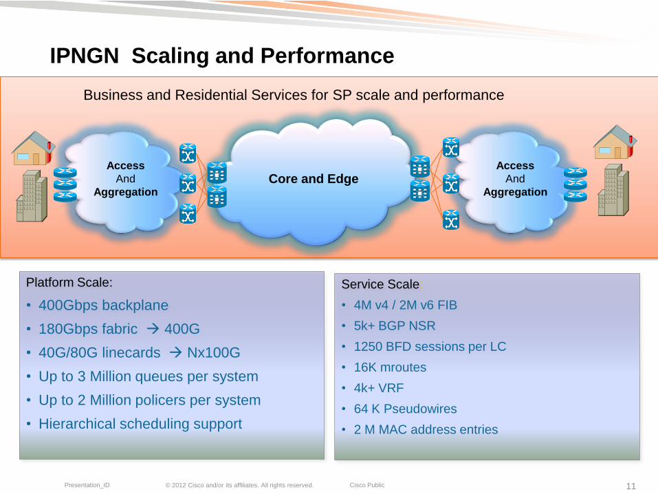
IPNGN Scaling and Performance
Access
And
Aggregation
Access
And
Aggregation Core and Edge
Platform Scale:
• 400Gbps backplane
• 180Gbps fabric 400G
• 40G/80G linecards Nx100G
• Up to 3 Million queues per system
• Up to 2 Million policers per system
• Hierarchical scheduling support
Service Scale:
• 4M v4 / 2M v6 FIB
• 5k+ BGP NSR
• 1250 BFD sessions per LC
• 16K mroutes
• 4k+ VRF
• 64 K Pseudowires
• 2 M MAC address entries
Business and Residential Services for SP scale and performance

© 2012 Cisco and/or its affiliates. All rights reserved. Cisco Public Presentation_ID 12
IP NGN Scaling – Number of Nodes
Transport CPE / NT
0000s–00000s
Access Nodes
10,00s–100,000s
Distribution Nodes
100s–1,000s
IP Edge Nodes
10–100s
Core Nodes
few–10s
Aggregation Nodes
1,000s–10,000s
As MPLS moves into aggregation and access number of nodes increases sharply

© 2012 Cisco and/or its affiliates. All rights reserved. Cisco Public Presentation_ID 13
Requirements for Simplified Operation
Reduction of number of operational points
Possibility of easy provisioning of services: L3VPN, VPWS, VPLS, without PW-stitching or Inter-AS mechanisms
Providing end-to-end MPLS transport
Keep IGP areas separated and routing tables small
Fast convergence
Easy configuration and troubleshooting
Ability to integrate with any access technology
IPv6 Readiness

MPLS Network Architecture Evolution

© 2012 Cisco and/or its affiliates. All rights reserved. Cisco Public Presentation_ID 15
Evolving MPLS Networks Classical Model
Edge Edge Core
Agg
Access Access Agg
IP
L2 L2
L2VPN
L3VPN
L2VPN
L3VPN
MPLS
Segmented networks (IGP)
MPLS core
L2 & L3VPN services on Core-Edge
Traditional/Native Access and Aggregation
Cisco ME 3.0, 3.1, etc architectures in the past…

© 2012 Cisco and/or its affiliates. All rights reserved. Cisco Public Presentation_ID 16
Evolving MPLS Networks Next Gen Model I
Edge Edge Core Agg Access Access Agg
IP
L2 + IP L2 + IP
L3VPN L3VPN
MPLS
L2VPN L2VPN
Segmented Networks
MPLS core
IP+MPLS extended to Aggregation, simplifying Aggregation-to-Core-Edge networks
L3VPN services on Core-Edge
Most of today’s network, like Cisco IP NGN Release 1.8

© 2012 Cisco and/or its affiliates. All rights reserved. Cisco Public Presentation_ID 17
Evolving MPLS Networks Next Gen Model II
Segmented Networks
MPLS core
L3VPN services on Core-Edge
IP+MPLS extended to Access to provide seamless end-end L2VPN service
Requires L2VPN on mid-point devices
This model is possible in most of today’s networks, but rarely utilized
Edge Edge Core
Agg
Access Access
Agg
IP
IP IP
L2VPN L2VPN
MPLS
L2VPN L2VPN
L2VPN
PW

© 2012 Cisco and/or its affiliates. All rights reserved. Cisco Public Presentation_ID 18
Evolving MPLS Networks Next Gen Model II
Supporting multiple L2VPN Pseudowire (PW) segments requires provisioning and storing L2VPN information on mid-pint devices
Increases design, deployment and management complexities to achieve scalable fast converging network
Edge Edge Core
Agg
Access Access
Agg
IP
IP IP
L2VPN L2VPN
MPLS
L2VPN L2VPN
L2VPN
PW

© 2012 Cisco and/or its affiliates. All rights reserved. Cisco Public Presentation_ID 19
Evolving MPLS Networks : Target Architecture
A single PW segment over a multi-segmented transport without multi-domain complexities would be an ideal solution
Edge Edge Core
Agg
Access Access
Agg
IP
IP IP
L3VPN L3VPN
MPLS
L2VPN L2VPN
L2VPN
PW

© 2012 Cisco and/or its affiliates. All rights reserved. Cisco Public Presentation_ID 20
Unified MPLS Design Goals & Reference Model
1k Nodes / Core
10k Nodes / Aggregation
100k Nodes / Access
Scale - Interconnect 100k Access nodes through an MPLS domain
Resilience - < 50msec convergence as often as possible
Simplicity - Operation of big MPLS networks is often considered difficult
IGP2 IGP1 IGP3
DSLAM1
PE11
PE12
ABR11
ABR12
ABR21
ABR22
PE21
PE22
DSLAM2
Core and Edge Distribution /
Aggregation
Distribution /
Aggregation

Unified MPLS Architecture

© 2012 Cisco and/or its affiliates. All rights reserved. Cisco Public Presentation_ID 22
Unified MPLS Architecture
Access, Aggregation and Core are in different IGP areas
No or very limited IGP route redistribution from Core towards Aggregation areas
Every nodes are in the same BGP AS
RFC 3107 for label distribution (prefix+label through BGP):
- PE loopbacks
- Central Infrastructure: Edge Nodes, etc
ABRs between IGP areas also act as BGP RRs
- Next-hop self for inserting ABRs into the Data Path
- Loop avoidance via Cluster-id
BGP Additional-path + existing mechanisms for Fast convergence

© 2012 Cisco and/or its affiliates. All rights reserved. Cisco Public Presentation_ID 23
Unified MPLS High-level View
Aggregati
on
Domain 1 Core
Aggregati
on
Domain 2 PE1
PE2
ABR-RR1 ABR-RR2
ABR-RR3 ABR-RR4
IGP area 1 IGP area 2 IGP area 3
BGP AS

© 2012 Cisco and/or its affiliates. All rights reserved. Cisco Public Presentation_ID 24
iBGP Peering between Access and Aggregation
ABR-RR1 ABR-RR2
PE1 PE2
Next-Hop-Self Next-Hop-Self
iBGP peers
iBGP peers
iBGP peers
IGP 1 IGP 2 IGP 3
ABRs are also Route Reflectors
PEs in the same segment peer with ABR-RRs
RRs are inserted in data path by setting next-hop-self

© 2012 Cisco and/or its affiliates. All rights reserved. Cisco Public Presentation_ID 25
Aggregation
Exchange of Route and Label information between Domains iBGP + Labels (RFC 3107)
Aggregation Core PE1 PE2
iBGP IPv4 update:
PE1
Label=(L1)
NH=ABR-RR2
iBGP IPv4 update:
PE2
Label=(L4)
NH=ABR-RR1
ABR-RR1 ABR-RR2
iBGP IPv4 update:
PE2
Label=(L3)
NH=ABR-RR2
iBGP IPv4 update:
PE1
Label=(L2)
NH=ABR-RR1
BGP updates include labels for IPv4 prefixes
Only share PE loopbacks with other segments

© 2012 Cisco and/or its affiliates. All rights reserved. Cisco Public Presentation_ID 26
L2VPN Circuit Establishment
PE1 and PE2 exchange PW Virtual Circuit labels as usual
ABR-RR1 ABR-RR2
PE1 PE2
GE0/1
VCID:X
GE0/1
VCID:X
VCID:X
Label:Y
VCID:X
Label:Z
PW

© 2012 Cisco and/or its affiliates. All rights reserved. Cisco Public Presentation_ID 27
Aggregation
Traffic Forwarding & Label Stacks
Aggregation Core
ABR-RR1 ABR-RR2 PE1 PE2
Egress PE pops VC label
IGP and BGP labels are exchanged
Z
21
L4
Z
22
L3 Z
23
BGP Label
IGP Label
PW VC Label
Payload

© 2012 Cisco and/or its affiliates. All rights reserved. Cisco Public Presentation_ID 28
High Availability & Fast Convergence
BGP Additional-path:
RR sends all paths for ABRs, and they perform path selection
RR performs path selection, sends path + additional path
Aggregation Aggregation Core
ABR-RR1 ABR-RR2
PE1 PE2
ABR-RR3 ABR-RR4
PE4
PE3
RR
(cluster-id 1) (cluster-id 2)
Today XR
Soon XE/IOS

Unified MPLS Configuration examples

© 2012 Cisco and/or its affiliates. All rights reserved. Cisco Public Presentation_ID 30
Unified MPLS Deployment Scenario –Topology used for this exercise
Segmented Networks with three separate IGP OSPF) Processes: Process 1, Process 2, Process 3
All network segments run MPLS
ABRs with Route Reflector functionality
End-to-End LSP transport between PEs
PEs are RR clients of immediate ABR RRs
© 2012 Cisco and/or its affiliates. All rights reserved. Cisco Public Presentation_ID 31
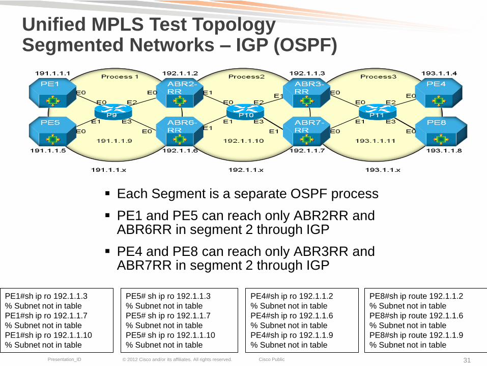
Unified MPLS Test Topology Segmented Networks – IGP (OSPF)
Each Segment is a separate OSPF process
PE1 and PE5 can reach only ABR2RR and ABR6RR in segment 2 through IGP
PE4 and PE8 can reach only ABR3RR and ABR7RR in segment 2 through IGP
PE1#sh ip ro 192.1.1.3
% Subnet not in table
PE1#sh ip ro 192.1.1.7
% Subnet not in table
PE1#sh ip ro 192.1.1.10
% Subnet not in table
PE5# sh ip ro 192.1.1.3
% Subnet not in table
PE5# sh ip ro 192.1.1.7
% Subnet not in table
PE5# sh ip ro 192.1.1.10
% Subnet not in table
PE4#sh ip ro 192.1.1.2
% Subnet not in table
PE4#sh ip ro 192.1.1.6
% Subnet not in table
PE4#sh ip ro 192.1.1.9
% Subnet not in table
PE8#sh ip route 192.1.1.2
% Subnet not in table
PE8#sh ip route 192.1.1.6
% Subnet not in table
PE8#sh ip route 192.1.1.9
% Subnet not in table

© 2012 Cisco and/or its affiliates. All rights reserved. Cisco Public Presentation_ID 32
Redistribute only ABR2RR & ABR6RR loopbacks into OSPF Process 1
ABR2RR#
!
router ospf 1
redistribute ospf 2 subnets match internal external 1 external 2 route-map OSPF2INTo1
!
access-list 1 permit 192.1.1.2
!
route-map OSPF2INTo1 permit 10
match ip address 1
!
Unified MPLS Test Topology Segmented Networks – Limited Loopback propagation via IGP to allow iBGP peering
ABR3RR#
!
router ospf 3
redistribute ospf 2 subnets match internal external 1 external 2 route-map OSPF2Into3
!
access-list 1 permit 192.1.1.3
!
route-map OSPF2Into3 permit 10
match ip address 1
!

© 2012 Cisco and/or its affiliates. All rights reserved. Cisco Public Presentation_ID 33
Unified MPLS Test Topology Segmented Networks – Segment 1 IGP routes
PE5#sh ip route 191.1.0.0/16 is variably subnetted, 8 subnets, 2 masks
O 191.1.1.1/32 [110/21] via 191.1.5.1, 19:32:07, Ethernet0/0
C 191.1.1.5/32 is directly connected, Loopback0
O 191.1.1.9/32 [110/11] via 191.1.5.1, 19:32:07, Ethernet0/0
O 191.1.2.0/24 [110/20] via 191.1.5.1, 19:31:52, Ethernet0/0
O 191.1.3.0/24 [110/20] via 191.1.5.1, 19:32:07, Ethernet0/0
O 191.1.4.0/24 [110/20] via 191.1.5.1, 19:32:07, Ethernet0/0
C 191.1.5.0/24 is directly connected, Ethernet0/0
L 191.1.5.2/32 is directly connected, Ethernet0/0
192.1.1.0/32 is subnetted, 2 subnets
O E2 192.1.1.2 [110/1] via 191.1.5.1, 19:31:52, Ethernet0/0
O E2 192.1.1.6 [110/1] via 191.1.5.1, 19:32:07, Ethernet0/0

© 2012 Cisco and/or its affiliates. All rights reserved. Cisco Public Presentation_ID 34
Unified MPLS Test Topology Segmented Networks – IGP MPLS
PE1#sh mpls forwarding-table Local Outgoing Prefix Bytes Label Outgoing Next Hop Label Label or Tunnel Id Switched interface 18 Pop Label 191.1.1.9/32 0 Et0/0 191.1.4.1 19 Pop Label 191.1.5.0/24 0 Et0/0 191.1.4.1 20 Pop Label 191.1.2.0/24 0 Et0/0 191.1.4.1 21 Pop Label 191.1.3.0/24 0 Et0/0 191.1.4.1 22 21 192.1.1.6/32 0 Et0/0 191.1.4.1 23 23 191.1.1.5/32 0 Et0/0 191.1.4.1 24 24 192.1.1.2/32 0 Et0/0 191.1.4.1
PE5#sh mpls forwarding-table Local Outgoing Prefix Bytes Label Outgoing Next Hop Label Label or Tunnel Id Switched interface 17 Pop Label 191.1.1.9/32 0 Et0/0 191.1.5.1 18 22 191.1.1.1/32 0 Et0/0 191.1.5.1 19 Pop Label 191.1.2.0/24 0 Et0/0 191.1.5.1 20 Pop Label 191.1.3.0/24 0 Et0/0 191.1.5.1 21 Pop Label 191.1.4.0/24 0 Et0/0 191.1.5.1 22 21 192.1.1.6/32 0 Et0/0 191.1.5.1 23 24 192.1.1.2/32 0 Et0/0 191.1.5.1
P9#sh mpls forwarding-table Local Outgoing Prefix Bytes Label Outgoing Next Hop Label Label or Tunnel Id Switched interface 21 Pop Label 192.1.1.6/32 338741 Et3/0 191.1.3.2 22 Pop Label 191.1.1.1/32 340310 Et0/0 191.1.4.2 23 Pop Label 191.1.1.5/32 338947 Et1/0 191.1.5.2 24 Pop Label 192.1.1.2/32 340332 Et2/0 191.1.2.2
© 2012 Cisco and/or its affiliates. All rights reserved. Cisco Public Presentation_ID 35
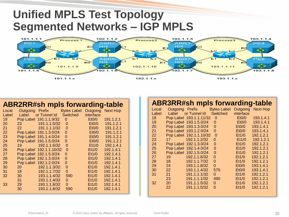
Unified MPLS Test Topology Segmented Networks – IGP MPLS
ABR2RR#sh mpls forwarding-table Local Outgoing Prefix Bytes Label Outgoing Next Hop Label Label or Tunnel Id Switched interface 19 Pop Label 191.1.1.9/32 0 Et0/0 191.1.2.1 20 23 191.1.1.5/32 0 Et0/0 191.1.2.1 21 22 191.1.1.1/32 0 Et0/0 191.1.2.1 22 Pop Label 191.1.3.0/24 0 Et0/0 191.1.2.1 23 Pop Label 191.1.4.0/24 0 Et0/0 191.1.2.1 24 Pop Label 191.1.5.0/24 0 Et0/0 191.1.2.1 25 19 192.1.1.6/32 0 Et1/0 192.1.4.1 26 Pop Label 192.1.1.10/32 0 Et1/0 192.1.4.1 27 Pop Label 192.1.5.0/24 0 Et1/0 192.1.4.1 28 Pop Label 192.1.3.0/24 0 Et1/0 192.1.4.1 29 Pop Label 192.1.2.0/24 0 Et1/0 192.1.4.1 30 20 192.1.1.3/32 0 Et1/0 192.1.4.1 31 18 192.1.1.7/32 0 Et1/0 192.1.4.1 32 30 193.1.1.4/32 590 Et1/0 192.1.4.1 31 193.1.1.4/32 0 Et1/0 192.1.4.1 33 29 193.1.1.8/32 0 Et1/0 192.1.4.1 30 193.1.1.8/32 590 Et1/0 192.1.4.1
ABR3RR#sh mpls forwarding-table Local Outgoing Prefix Bytes Label Outgoing Next Hop Label Label or Tunnel Id Switched interface 18 Pop Label 193.1.1.11/32 0 Et0/0 193.1.4.1 19 Pop Label 193.1.5.0/24 0 Et0/0 193.1.4.1 20 Pop Label 193.1.3.0/24 0 Et0/0 193.1.4.1 21 Pop Label 193.1.2.0/24 0 Et0/0 193.1.4.1 22 Pop Label 192.1.1.10/32 0 Et1/0 192.1.2.1 23 17 192.1.1.2/32 0 Et1/0 192.1.2.1 24 Pop Label 192.1.3.0/24 0 Et1/0 192.1.2.1 25 Pop Label 192.1.4.0/24 0 Et1/0 192.1.2.1 26 Pop Label 192.1.5.0/24 0 Et1/0 192.1.2.1 27 19 192.1.1.6/32 0 Et1/0 192.1.2.1 28 18 192.1.1.7/32 0 Et1/0 192.1.2.1 29 24 193.1.1.8/32 0 Et0/0 193.1.4.1 30 22 193.1.1.4/32 570 Et0/0 193.1.4.1 31 21 191.1.1.1/32 0 Et1/0 192.1.2.1 23 191.1.1.1/32 490 Et1/0 192.1.2.1 32 20 191.1.1.5/32 0 Et1/0 192.1.2.1 22 191.1.1.5/32 0 Et1/0 192.1.2.1

© 2012 Cisco and/or its affiliates. All rights reserved. Cisco Public Presentation_ID 36
Unified MPLS Test Topology Segmented Networks – iBGP peering
All segments are in the same BGP domain
PEs are clients of ABR RRs in the same segment
-PE1 and PE5 are iBGP peers with ABR2RR and ABR6RR
-PE4 and PE8 are iBGP peers with ABR3RR and ABR7RR

© 2012 Cisco and/or its affiliates. All rights reserved. Cisco Public Presentation_ID 37
Unified MPLS Test Topology Segmented Networks – seup iBGP Sessions
ABR2RR# & ABR6RR
!
router bgp 100
neighbor 191.1.1.1 remote-as 100
neighbor 191.1.1.1 update-source Loopback0
neighbor 191.1.1.5 remote-as 100
neighbor 191.1.1.5 update-source Loopback0
!
address-family ipv4
neighbor 191.1.1.1 activate
neighbor 191.1.1.1 route-reflector-client
neighbor 191.1.1.5 activate
neighbor 191.1.1.5 route-reflector-client
!
ABR3RR# & ABR7RR
!
router bgp 100
neighbor 193.1.1.4 remote-as 100
neighbor 193.1.1.4 update-source Loopback0
neighbor 193.1.1.8 remote-as 100
neighbor 19131.1.8 update-source Loopback0
!
address-family ipv4
neighbor 193.1.1.4 activate
neighbor 193.1.1.8 route-reflector-client
neighbor 193.1.1.4 activate
neighbor 193.1.1.8 route-reflector-client
!

© 2012 Cisco and/or its affiliates. All rights reserved. Cisco Public Presentation_ID 38
Unified MPLS Test Topology Segmented Networks – iBGP Sessions up
ABR2RR#sh ip bgp neighbors
BGP neighbor is 191.1.1.1, remote AS 100, internal link
BGP version 4, remote router ID 191.1.1.1
BGP state = Established, up for 22:00:41 …………………….snip……………….
BGP neighbor is 191.1.1.5, remote AS 100, internal link
BGP version 4, remote router ID 191.1.1.5
BGP state = Established, up for 22:05:34 …………………….snip……………….
BGP neighbor is 192.1.1.6, remote AS 100, internal link
BGP version 4, remote router ID 192.1.1.6
BGP state = Established, up for 22:12:12
ABR2RR#sh ip bgp neighbors
BGP neighbor is 192.1.1.3, remote AS 100, internal link
BGP version 4, remote router ID 192.1.1.3
BGP state = Established, up for 22:06:46 …………………….snip……………….
BGP neighbor is 192.1.1.7, remote AS 100, internal link
BGP version 4, remote router ID 192.1.1.7
BGP state = Established, up for 22:14:39

© 2012 Cisco and/or its affiliates. All rights reserved. Cisco Public Presentation_ID 39
Unified MPLS Test Topology Segmented Networks – Establishing LSPs End-to-End iBGP Next-Hop-Self is enabled on ABR RRs to insert ABR RRs in the
data path
ABR2RR & ABR6RR pair is in the different cluster id than ABR3RR & ABR7RR pair for loop avoidance
Use iBGP + Label to announce PEs loopbacks and labels through iBGP to build end-to-end LSPs
Redistribute IGP into BGP, to get PE loopbacks into BGP table
Use filters (IPv4+Labels) to allow only desired PE loopbacks + labels to be propagated
Each ABR RRs allocate labels for PEs loopbacks and propagate PE NLRIs through iBGP only
iBGP multipath allows to store multipaths in the FIB table for load balancing - installing paths to both RRs on PEs
PEs in segment 1 can reach PEs in segment 3 allowing to build PWs directly between Access PEs located in different segments

© 2012 Cisco and/or its affiliates. All rights reserved. Cisco Public Presentation_ID 40
Unified MPLS Test Topology Segmented Networks – iBGP Multipath
!
address-family ipv4
maximum-paths ibgp 2
exit-address-family
!
Traffic should be able to utilize any path in the network
iBGP multipath allows to store multiple paths in the FIB table for load balancing - installing paths to both RRs on PEs.
PE1 should be able to forward traffic to ABR2RR and ABR6RR. Similarly, ABR2RR should be able to forward traffic to both ABR3RR and ABR7RR
Enable iBGP multipath functionality on all devices

© 2012 Cisco and/or its affiliates. All rights reserved. Cisco Public Presentation_ID 41
Unified MPLS Test Topology Segmented Networks – iBGP Multipath
PE1# & PE5# sh ip bgp nexthops
# Paths Nexthop Address
9 192.1.1.2
9 192.1.1.6
PE4 & PE8# sh ip bgp nexthops
# Paths Nexthop Address
9 192.1.1.7
9 192.1.1.3
ABR2RR#sh ip bgp nexthops
# Paths Nexthop Address
7 192.1.1.6
6 191.1.2.1
2 192.1.1.7
2 192.1.1.3
ABR6RR#sh ip bgp nexthops
# Paths Nexthop Address
7 192.1.1.2
6 191.1.3.1
2 192.1.1.7
2 192.1.1.3
ABR3RR#sh ip bgp nexthops
# Paths Nexthop Address
2 192.1.1.2
2 192.1.1.6
7 192.1.1.7
6 193.1.4.1
ABR7RR#sh ip bgp nexthops
# Paths Nexthop Address
2 192.1.1.2
2 192.1.1.6
7 192.1.1.3
6 193.1.5.1

© 2012 Cisco and/or its affiliates. All rights reserved. Cisco Public Presentation_ID 42
Unified MPLS Test Topology Segmented Networks – iBGP Multiple paths reflected
PE1#sh bgp 193.1.1.4 BGP routing table entry for 193.1.1.4/32, version 17
Paths: (2 available, best #2, table default)
Multipath: iBGP
Not advertised to any peer
Refresh Epoch 1
Local
192.1.1.6 (metric 1) from 192.1.1.6 (192.1.1.6)
Origin incomplete, metric 21, localpref 100, valid, internal, multipath(oldest) Originator: 192.1.1.3, Cluster list: 0.0.0.1
mpls labels in/out nolabel/31
Refresh Epoch 1
Local
192.1.1.2 (metric 1) from 192.1.1.2 (192.1.1.2)
Origin incomplete, metric 21, localpref 100, valid, internal, multipath, best Originator: 192.1.1.3, Cluster list: 0.0.0.1
mpls labels in/out nolabel/32
For example: to reach PE4, two paths are reflected on PE1

© 2012 Cisco and/or its affiliates. All rights reserved. Cisco Public Presentation_ID 43
Unified MPLS Test Topology Segmented Networks – iBGP Next Hop Self
!
address-family ipv4
neighbor 192.1.1.2 next-hop-self all
neighbor 192.1.1.6 next-hop-self all
neighbor 192.1.1.7 next-hop-self all
neighbor 193.1.1.4 next-hop-self all
neighbor 193.1.1.8 next-hop-self all
exit-address-family
!
iBGP Next-Hop-Self is enabled on ABR RRs towards each BGP peer to insert ABR RRs in the data path
Sample configuration on ABR3RR

© 2012 Cisco and/or its affiliates. All rights reserved. Cisco Public Presentation_ID 44
Unified MPLS Test Topology Segmented Networks – iBGP Next Hop Self
! Sample configuration on ABR3RR
address-family ipv4
redistribute ospf 3
neighbor 192.1.1.2 route-map OUT out
neighbor 192.1.1.6 route-map OUT out
!
*Filter is not needed towards PEs
Redistribute IGP into BGP, to get PE loopbacks into BGP table on ABR RRs (only)
Use filters (IPv4+Labels) to allow only the desired PE loopbacks + labels to be propagated to other segments (ABR RR to ABR RR)
!Sample configuration on ABR3RR
access-list 2 permit 193.1.1.4 log
access-list 2 permit 193.1.1.8 log
!
route-map OUT permit 11
match ip address 2
set mpls-label
!

© 2012 Cisco and/or its affiliates. All rights reserved. Cisco Public Presentation_ID 45
Unified MPLS Test Topology Segmented Networks – iBGP + Label
! Sample configuration on ABR3RR
address-family ipv4
neighbor 192.1.1.2 send-label
neighbor 192.1.1.6 send-label
neighbor 192.1.1.7 send-label
neighbor 193.1.1.4 send-label
neighbor 193.1.1.8 send-label
exit-address-family
!
Use iBGP + Label to announce PEs loopbacks and labels through iBGP to build end-to-end LSPs
Enable RFC 3107 on all PEs and ABR RRs as ―send-label‖ capability needs to be negotiated between peers

© 2012 Cisco and/or its affiliates. All rights reserved. Cisco Public Presentation_ID 46
Unified MPLS Test Topology Segmented Networks – BGP Lables
ABR2RR#sh bgp ipv4 unicast labels
Network Next Hop In label/Out label
191.1.1.1/32 192.1.1.6 21/23
191.1.2.1 21/nolabel
191.1.1.5/32 192.1.1.6 20/22
191.1.2.1 20/nolabel
193.1.1.4/32 192.1.1.7 32/31
192.1.1.3 32/30
193.1.1.8/32 192.1.1.7 33/30
192.1.1.3 33/29
ABR3RR#sh bgp ipv4 unicast labels
Network Next Hop In label/Out label
191.1.1.1/32 192.1.1.2 31/21
192.1.1.6 31/23
191.1.1.5/32 192.1.1.2 32/20
192.1.1.6 32/22
193.1.1.4/32 192.1.1.7 30/31
193.1.4.1 30/nolabel
193.1.1.8/32 192.1.1.7 29/30
193.1.4.1 29/nolabel
© 2012 Cisco and/or its affiliates. All rights reserved. Cisco Public Presentation_ID 47
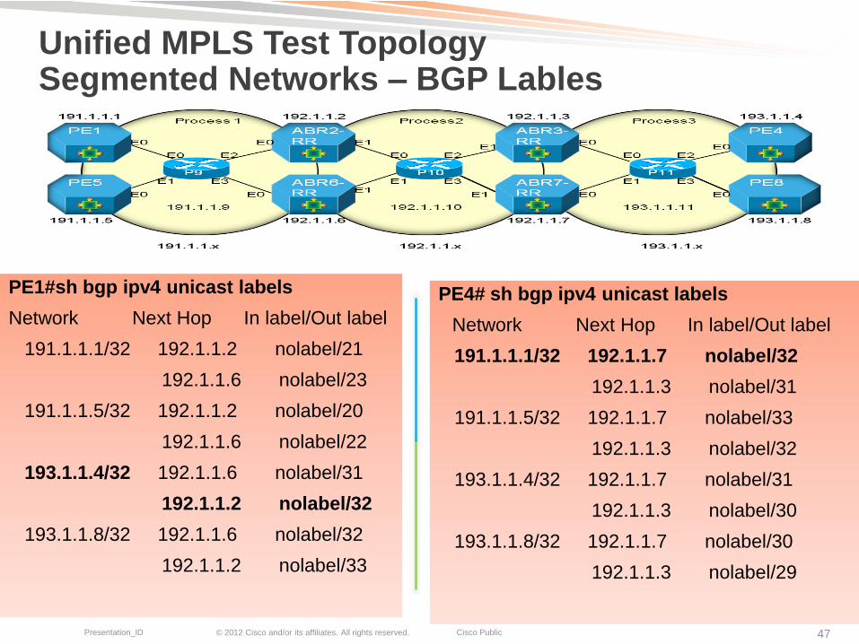
Unified MPLS Test Topology Segmented Networks – BGP Lables
PE1#sh bgp ipv4 unicast labels
Network Next Hop In label/Out label
191.1.1.1/32 192.1.1.2 nolabel/21
192.1.1.6 nolabel/23
191.1.1.5/32 192.1.1.2 nolabel/20
192.1.1.6 nolabel/22
193.1.1.4/32 192.1.1.6 nolabel/31
192.1.1.2 nolabel/32
193.1.1.8/32 192.1.1.6 nolabel/32
192.1.1.2 nolabel/33
PE4# sh bgp ipv4 unicast labels
Network Next Hop In label/Out label
191.1.1.1/32 192.1.1.7 nolabel/32
192.1.1.3 nolabel/31
191.1.1.5/32 192.1.1.7 nolabel/33
192.1.1.3 nolabel/32
193.1.1.4/32 192.1.1.7 nolabel/31
192.1.1.3 nolabel/30
193.1.1.8/32 192.1.1.7 nolabel/30
192.1.1.3 nolabel/29

© 2012 Cisco and/or its affiliates. All rights reserved. Cisco Public Presentation_ID 48
Unified MPLS Test Topology Segmented Networks – BGP Routes
PE5#sh ip route
193.1.1.0/32 is subnetted, 2 subnets
B 193.1.1.4 [200/21] via 192.1.1.6, 1d00h
[200/21] via 192.1.1.2, 1d00h
B 193.1.1.8 [200/21] via 192.1.1.6, 1d00h
[200/21] via 192.1.1.2, 1d00h
PE1#sh ip route
193.1.1.0/32 is subnetted, 2 subnets
B 193.1.1.4 [200/21] via 192.1.1.6, 1d00h
[200/21] via 192.1.1.2, 1d00h
B 193.1.1.8 [200/21] via 192.1.1.6, 1d00h
[200/21] via 192.1.1.2, 1d00h
ABR2RR#sh ip route
193.1.1.0/32 is subnetted, 2 subnets
B 193.1.1.4 [200/21] via 192.1.1.7, 1d00h
[200/21] via 192.1.1.3, 1d00h
B 193.1.1.8 [200/21] via 192.1.1.7, 1d00h
[200/21] via 192.1.1.3, 1d00h
ABR6RR#sh ip route
193.1.1.0/32 is subnetted, 2 subnets
B 193.1.1.4 [200/21] via 192.1.1.7, 1d00h
[200/21] via 192.1.1.3, 1d00h
B 193.1.1.8 [200/21] via 192.1.1.7, 1d00h
[200/21] via 192.1.1.3, 1d00h

© 2012 Cisco and/or its affiliates. All rights reserved. Cisco Public Presentation_ID 49
Unified MPLS Test Topology Segmented Networks – Enabling L2VPN service
PEs in segment 1 can reach PEs in segment 3 allowing to build PWs directly between Access PEs located in different segments
!PE1 interface Ethernet0/1
no ip address
xconnect 193.1.1.4 14 encapsulation mpls
!
!PE4 !
interface Ethernet0/1
no ip address
xconnect 191.1.1.1 14 encapsulation mpls
!

© 2012 Cisco and/or its affiliates. All rights reserved. Cisco Public Presentation_ID 50
Unified MPLS Test Topology Segmented Networks – Enabling L2VPN service
PEs in segment 1 can reach PEs in segment 3 allowing to build PWs directly between Access PEs located in different segments
!PE5 interface Ethernet0/1
no ip address
xconnect 193.1.1.8 58 encapsulation mpls
!
!PE8 !
interface Ethernet0/1
no ip address
xconnect 191.1.1.5 58 encapsulation mpls
!

© 2012 Cisco and/or its affiliates. All rights reserved. Cisco Public Presentation_ID 51
Unified MPLS Test Topology L2VPN Pseudowire Circuit Verification
PE1#sh mpls l2transport vc 14 detail
Local interface: Et0/1 up, line protocol up, Ethernet up
Destination address: 193.1.1.4, VC ID: 14, VC status: up
Output interface: Et0/0, imposed label stack {23 32 16} Preferred path: not configured
Default path: active
Next hop: 191.1.4.1
Create time: 00:20:47, last status change time: 00:18:53
Signaling protocol: LDP, peer 193.1.1.4:0 up
Targeted Hello: 191.1.1.1(LDP Id) -> 193.1.1.4, LDP is UP
MPLS VC labels: local 16, remote 16
PWID: 4096
-----------------------------------------snip-------------------------------------- 16: PW VC Label
32: BGP (PE) Label
23: IGP label

© 2012 Cisco and/or its affiliates. All rights reserved. Cisco Public Presentation_ID 52
Unified MPLS Test Topology L2VPN Pseudowire Circuit Verification
PE4#sh mpls l2transport vc 14 detail
Local interface: Et0/1 up, line protocol up, Ethernet up
Destination address: 191.1.1.1, VC ID: 14, VC status: up
Output interface: Et0/0, imposed label stack {22 32 16} Preferred path: not configured
Default path: active
Next hop: 193.1.2.1
Create time: 00:24:29, last status change time: 00:23:30
Signaling protocol: LDP, peer 191.1.1.1:0 up
Targeted Hello: 193.1.1.4(LDP Id) -> 191.1.1.1, LDP is UP
MPLS VC labels: local 16, remote 16
PWID: 4096
----------------------------------------snip------------------------------
16: PW VC Label
32: BGP (PE) Label
22: IGP label

© 2012 Cisco and/or its affiliates. All rights reserved. Cisco Public Presentation_ID 53
Unified MPLS Test Topology L2VPN Pseudowire forwarding Verification
PE1# ping mpls pseudowire 193.1.1.4 14 source 191.1.1.1
Sending 5, 100-byte MPLS Echos to 193.1.1.4,
timeout is 2 seconds, send interval is 0 msec:
----------------snip-----------------------------------------------------------
Type escape sequence to abort.
!!!!!
Success rate is 100 percent (5/5), round-trip min/avg/max = 4/4/5 ms

Further Developments for Scale and Convergence
© 2012 Cisco and/or its affiliates. All rights reserved. Cisco Public Presentation_ID 55
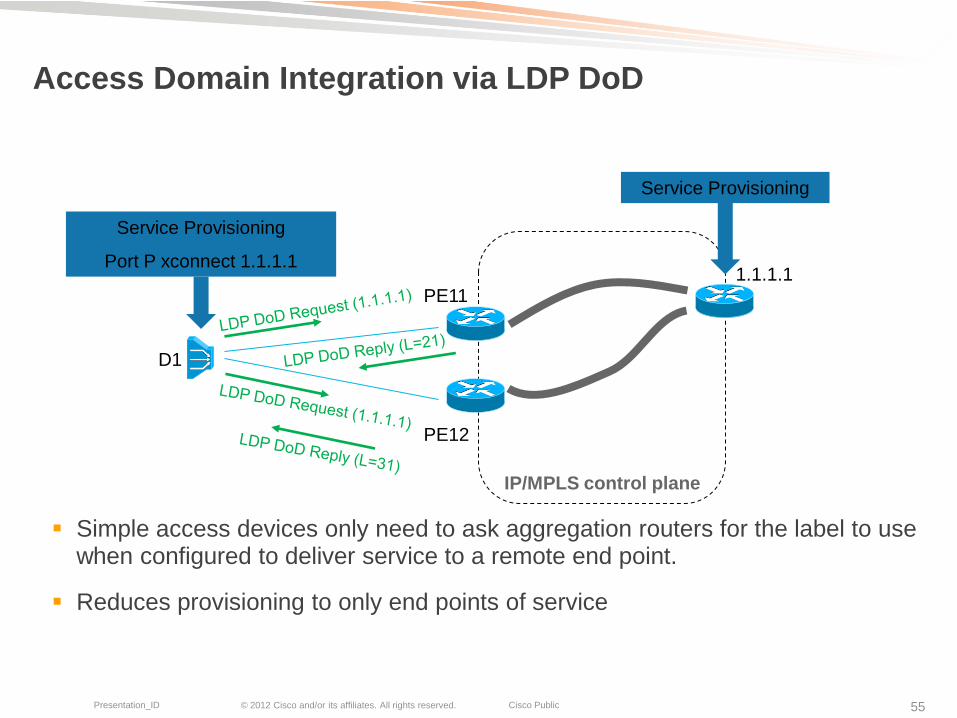
Access Domain Integration via LDP DoD
Simple access devices only need to ask aggregation routers for the label to use when configured to deliver service to a remote end point.
Reduces provisioning to only end points of service
D1
PE11
PE12
1.1.1.1
Service Provisioning
Port P xconnect 1.1.1.1
Service Provisioning
IP/MPLS control plane
© 2012 Cisco and/or its affiliates. All rights reserved. Cisco Public Presentation_ID 56
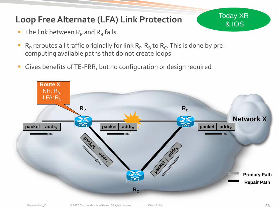
Loop Free Alternate (LFA) Link Protection
The link between RP and RB fails.
RP reroutes all traffic originally for link RP-RB to RC. This is done by pre-computing available paths that do not create loops
Gives benefits of TE-FRR, but no configuration or design required
RP RB
RC
Network X packet addrX packet addrX
Primary Path
Repair Path
packet addrX
Route X:
NH: RB,
LFA: RC
Today XR
& IOS

© 2012 Cisco and/or its affiliates. All rights reserved. Cisco Public Presentation_ID 57
BGP Prefix-Independent Protection (PIC)
50msec protection
Prefix-Independent
Default behavior, entirely automated computation
No operator involvement
Algorithm uses a pointer to move all prefixes to new next hop, not a hop by hop calculation as in the past.
Enables 3107 BGP+labels operation to scale via hierarchy while maintaining fast convergence characteristics
PE3 Cust1
Cust2
PE1
PE2

© 2012 Cisco and/or its affiliates. All rights reserved. Cisco Public Presentation_ID 58
Scalability through ‘Divide & Conquer’
Disconnect & Isolate IGP domains
- No more end-to-end IGP view
Leverage BGP for infrastructure (i.e. PE) routes
- Also for infrastructure (i.e. PE) labels
Backbone
Aggregation
.
Access Region 2
.
R
Access
.
Region1
.
Aggregation
ISIS Level 2
Or
OSPF Area 0
ISIS Level 1
Or
OSPF Area X
ISIS Level 1
Or
OSPF Area Y
Isolated IGP & LDP Isolated IGP & LDP Isolated IGP & LDP
BGP for Infrastructure
BGP for Services

© 2012 Cisco and/or its affiliates. All rights reserved. Cisco Public Presentation_ID 59
References
draft-ietf-mpls-seamless-mpls-00
draft-ietf-idr-aigp-06
draft-ietf-idr-add-paths-06
draft-shand-remote-lfa-00
draft-ietf-rtgwg-lfa-applicability-03
Cisco Unified MPLS Mobile Transport 1.0 (will be on CCO soon)

BRKSPG- 3305
Recommended Reading

© 2012 Cisco and/or its affiliates. All rights reserved. Cisco Public Presentation_ID 61

© 2012 Cisco and/or its affiliates. All rights reserved. Cisco Public Presentation_ID 62
Thank you.