sbrt treatment planning: practical...
TRANSCRIPT
SBRT Treatment Planning: Practical Considerations
Linda Hong, Ph.D.Montefiore Medical Center
Albert Einstein College of MedicineBronx, New York

I have no conflicts of interest to disclose.

Outlines• The Basic Principles of SBRT Treatment Planning
Conventional fractionated plan vs. SBRT plan Cranial SRS plan vs. SBRT plan
• Practical Considerations on SBRT Treatment Planning Spine Lung Liver
• Lessons learned from our experiences

Stereotactic Body Radiation Therapy (SBRT)
• Fractional dose >5Gyrange: 5 Gy to 34 Gy per fraction
• Number of fractions <5range: 1 to 5
• Safe delivery is of utmost importance due to high fractional dose and small number of fractions.

Montefiore-Einstein SBRT Experiences
• Started 1st SBRT Spine 1/2008• Started 1st SBRT Lung 4/2008• Started 1st SBRT Liver 8/2008• About 2 new SBRT cases weekly ever
since• Machines Varian Trilogy or Truebeam• Eclipse TPS

Spine1-3 lesions• Single Fraction: 16 Gy• Three Fraction: 24 Gy (8 Gy per fraction)
LungPeripheral Lesions• Three fractions: 60 Gy (20 Gy per fraction)Central Lesions• Five fractions: 50 Gy (10 Gy per fraction)
LiverMetastasis• If lesions > 2cm from Porta Hepatis/Bile Duct: Three Fractions 20Gy x 3• If lesions ≤ 2cm from Porta Hepatis/Bile Duct: Five Fractions 10Gy x 5
Hepatocellular Carcinoma• Five fractions: 30-50 Gy (depends on Veff)
Montefiore-Einstein Cancer Center (MECC) SBRT Registry

RTOG SBRT Protocols
• 0631 Spine• 0813 and 0915 Lung• 0438 Liver
These protocols specify detailed requirements for treatment planning:
Dose PrescriptionTarget Coverage Dose Constraints

The Basics of Treatment Planning for SBRT• The goal of SBRT treatment is to “ablate” tissues within
the PTV, these tissues were not considered at risk for complications. Dose inhomogeneity inside the PTV was considered acceptable (potentially advantageous) and not considered a priority in plan design.Maximum point dose up to 160% of Prescription Dose is common for SBRT plans.
• The main objective of the plan is to minimize the volume of those normal tissues outside PTV receiving high dose per fraction.
PTV
Beam Margin
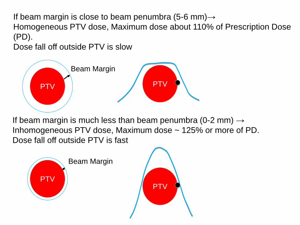
If beam margin is close to beam penumbra (5-6 mm)→Homogeneous PTV dose, Maximum dose about 110% of Prescription Dose (PD).Dose fall off outside PTV is slow
PTV
Beam Margin
If beam margin is much less than beam penumbra (0-2 mm) →Inhomogeneous PTV dose, Maximum dose ~ 125% or more of PD.Dose fall off outside PTV is fast
PTV
PTV

FIG. 3. a Conformity index (Ratio of PD Volume to PTV Volume) vs. homogeneity index.
FIG. 1. Homogeneity index (Ratio of Maximum PTV Dose to the PD) vs. beam margin.
Hong et al.: LINAC-based SRS: Inhomogeneity, conformity, and dose fall off, Med. Phys., Vol. 38, No. 3, March 2011
Cranial SRS Planning
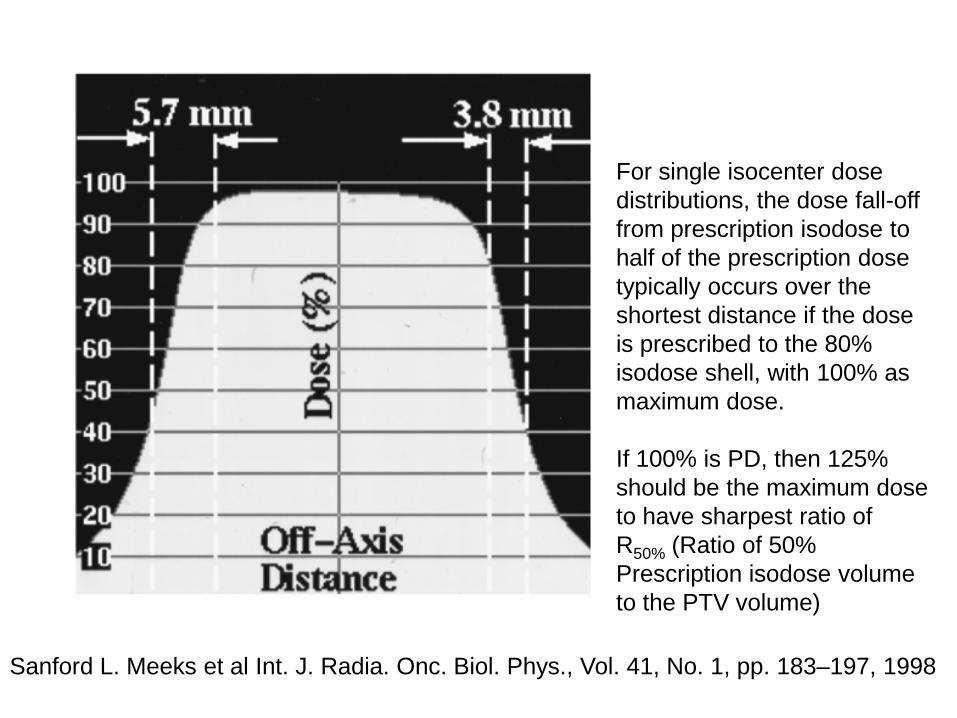
Sanford L. Meeks et al Int. J. Radia. Onc. Biol. Phys., Vol. 41, No. 1, pp. 183–197, 1998
For single isocenter dose distributions, the dose fall-off from prescription isodose to half of the prescription dose typically occurs over the shortest distance if the dose is prescribed to the 80% isodose shell, with 100% asmaximum dose.
If 100% is PD, then 125% should be the maximum dose to have sharpest ratio ofR50% (Ratio of 50% Prescription isodose volume to the PTV volume)
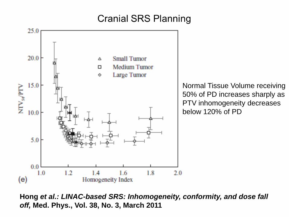
Hong et al.: LINAC-based SRS: Inhomogeneity, conformity, and dose fall off, Med. Phys., Vol. 38, No. 3, March 2011
Normal Tissue Volume receiving50% of PD increases sharply asPTV inhomogeneity decreasesbelow 120% of PD
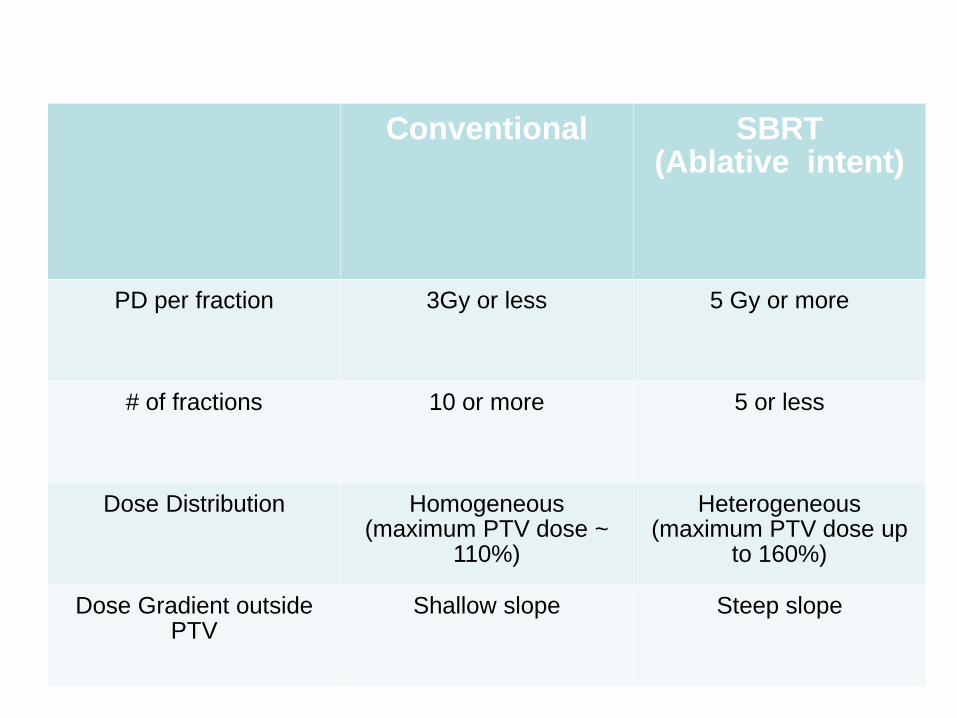
Conventional SBRT (Ablative intent)
PD per fraction 3Gy or less 5 Gy or more
# of fractions 10 or more 5 or less
Dose Distribution Homogeneous (maximum PTV dose ~
110%)
Heterogeneous (maximum PTV dose up
to 160%)
Dose Gradient outside PTV
Shallow slope Steep slope

20Gy x 3 plan is different from 2Gy x 30 plana small lung lesion example (PTV volume 33cc)
SBRT Conventional
# of Beams 11 11 3
Beam Margin (mm) 1 5 5
PD per fraction 20 Gy 2 Gy 2 Gy
Max PTV Dose (%) 124.2% 110.8% 110.0%
V100% 38.6 cc 44.3 cc(5.7 cc more)
87.5 cc(48.9 cc more)
V50% (R50%) 146.3 cc (4.4) 212.4 cc (6.4)(66cc more)
417.3 cc (12.6)(271 cc more)
V 25% 630.4 cc 799.2 cc (169 cc more)
756.8 cc(126 cc more)
50% PD 10 Gy 1 Gy 1 Gy
All Plans normalized to PTV V100% = 95%

For SBRT plans
Prescription Isodose level is usually not 100% PD covering 100% PTV
Often 95% PD covering 95% PTV or higherOr 100% PD covering 95% PTV or higher
This coverage was chosen because of the increased tissue volumes that must be irradiated to cover the corners of the PTV on each consecutive CT slice if 100% coverage is required.
For conventional plans
Often 100% PD dose to 100% PTV
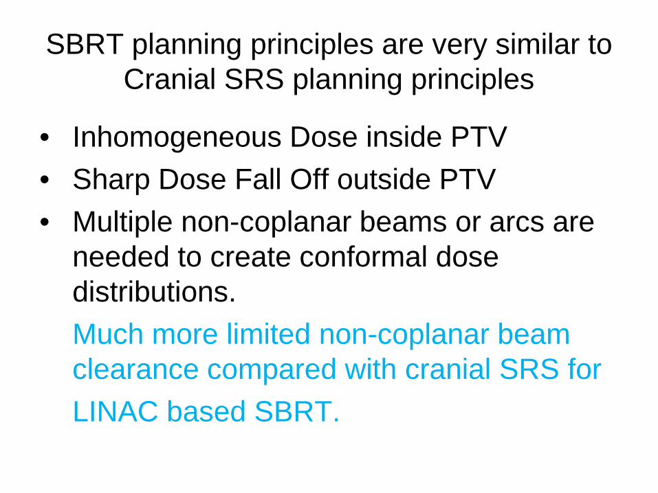
SBRT planning principles are very similar toCranial SRS planning principles
• Inhomogeneous Dose inside PTV• Sharp Dose Fall Off outside PTV• Multiple non-coplanar beams or arcs are
needed to create conformal dose distributions.Much more limited non-coplanar beam clearance compared with cranial SRS forLINAC based SBRT.
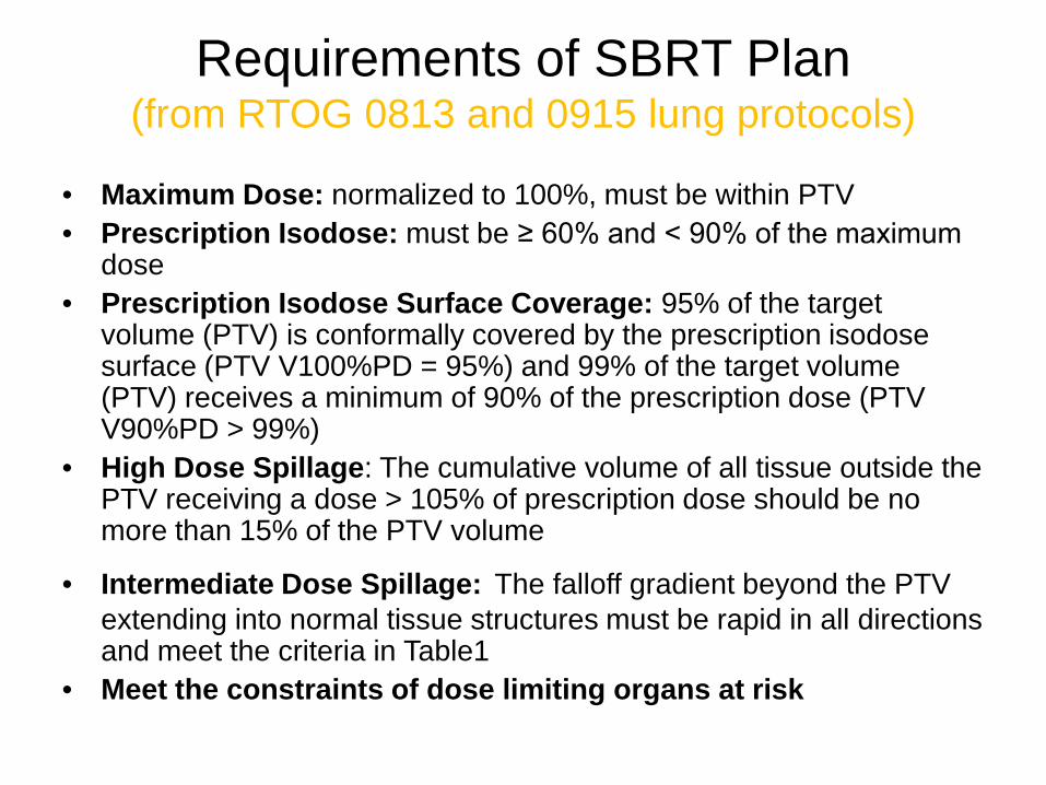
Requirements of SBRT Plan (from RTOG 0813 and 0915 lung protocols)
• Maximum Dose: normalized to 100%, must be within PTV• Prescription Isodose: must be ≥ 60% and < 90% of the maximum
dose• Prescription Isodose Surface Coverage: 95% of the target
volume (PTV) is conformally covered by the prescription isodose surface (PTV V100%PD = 95%) and 99% of the target volume (PTV) receives a minimum of 90% of the prescription dose (PTV V90%PD > 99%)
• High Dose Spillage: The cumulative volume of all tissue outside the PTV receiving a dose > 105% of prescription dose should be no more than 15% of the PTV volume
• Intermediate Dose Spillage: The falloff gradient beyond the PTV extending into normal tissue structures must be rapid in all directions and meet the criteria in Table1
• Meet the constraints of dose limiting organs at risk

RTOG 0813 (lung) and RTOG 0915 (lung) Table1

The published protocols usually do not specify R50% or D2cm requirements for spine and liver cases. Nevertheless, we find lung protocol criteria useful for spine and liver cases as well.

RTOG 0631 (Spine) Definition of Spine Metastasis Target Volume
Figure 2: Diagram of Spine Metastasis and Target Volume
An epidural lesion is included in the target volume providedthat there is a ≥ 3 mm gap between the spinal cord and the edge of the epidural lesion.
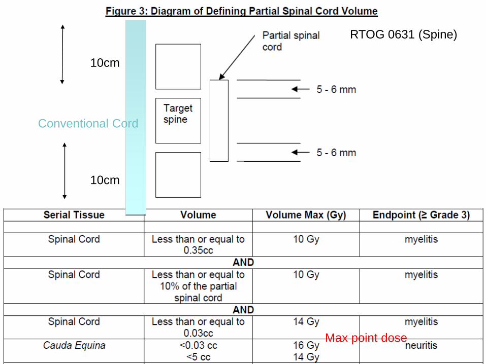
10cm
10cm
Conventional Cord
RTOG 0631 (Spine)
Max point dose
Montefiore-Einstein Cancer Center SBRT Registry Study
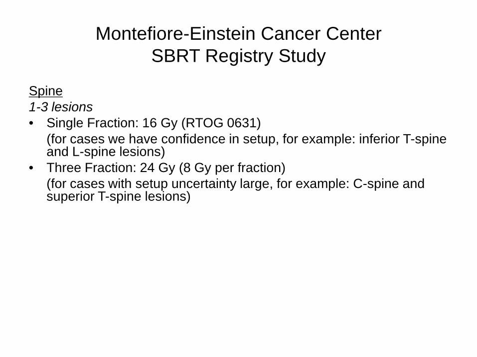
Spine1-3 lesions• Single Fraction: 16 Gy (RTOG 0631)
(for cases we have confidence in setup, for example: inferior T-spine and L-spine lesions)
• Three Fraction: 24 Gy (8 Gy per fraction) (for cases with setup uncertainty large, for example: C-spine and superior T-spine lesions)

For Spine Cases:IMRT or VMAT is required to create concave dose distributions.
We use two full RapidArcs, or two partial RapidArcs to avoid shoulders or arms, one arc with collimator at 0, the other with collimator at 90.
Multiple fixed IMRT fields can be used.
No need to do any non-coplanar beams (no clearance anyway).
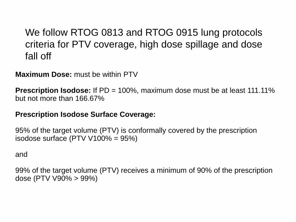
Maximum Dose: must be within PTV
Prescription Isodose: If PD = 100%, maximum dose must be at least 111.11% but not more than 166.67%
Prescription Isodose Surface Coverage:
95% of the target volume (PTV) is conformally covered by the prescription isodose surface (PTV V100% = 95%)
and
99% of the target volume (PTV) receives a minimum of 90% of the prescription dose (PTV V90% > 99%)
We follow RTOG 0813 and RTOG 0915 lung protocols criteria for PTV coverage, high dose spillage and dose fall off
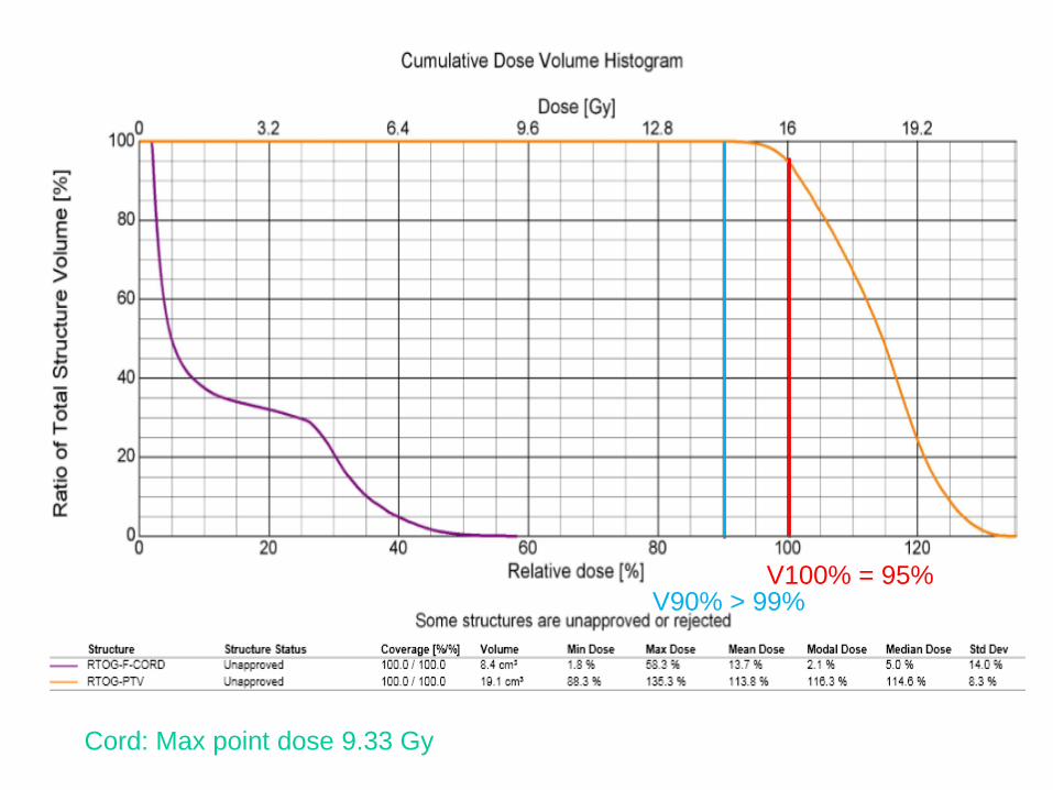
V100% = 95%V90% > 99%
Cord: Max point dose 9.33 Gy
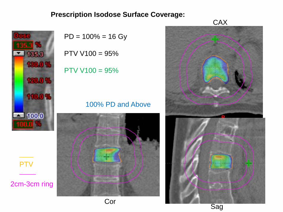
Prescription Isodose Surface Coverage:
PD = 100% = 16 Gy
PTV V100 = 95%
PTV V100 = 95%
CAX
CorSag
PTV
2cm-3cm ring
100% PD and Above

CAX
COR SAG
Prescription Isodose Surface Coverage:
PD = 100% = 16 Gy
PTV V90% > 99%
Here PTV V90% = 100%
90% PD and Above
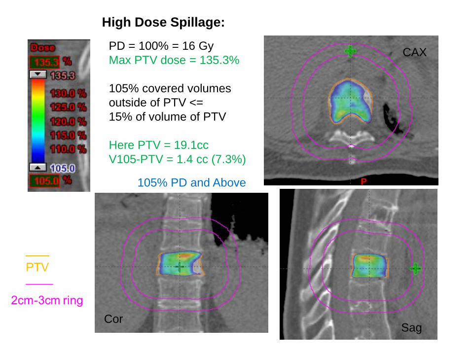
PD = 100% = 16 GyMax PTV dose = 135.3%
105% covered volumes outside of PTV <= 15% of volume of PTV
Here PTV = 19.1ccV105-PTV = 1.4 cc (7.3%)
CAX
CorSag
High Dose Spillage:
105% PD and Above

Conformality : Prescription Dose Volume vs. PTV Volume
PD = 100% = 16 Gy
V100 / PTV volume <= 1.2
Here PTV = 19.1ccV100 = 21.7 ccRatio = 1.14
CAX
CorSag
100% PD and Above

Intermediate Dose Spillage: R50% and D2cm
For PTV = 19.1 ccR50% < 4.6; D2cm = 52.7%
Here V50% = 77.0 ccR50% = 4.0D2cm = 43.6%
D2cm : Maximum dose in % of PD at 2cm beyond PTV in any direction
R50% : Ratio of 50% PD volume/PTV volume
CAX
SAG
COR
50% PD and Above

CAX
CORSAG
25% PD and Above
No need to do any non-coplanar beams (no clearance anyway).

CAX
Cor SAG
12.5% PD and Above
16Gy x 12.5% = 2Gy

Single Arc Collimator 45
Two Arcs: Collimator 0 and 90100% PD and Above
CAX
CAX
COR
COR
SAG
SAG
PTV 2cm-3cm ring
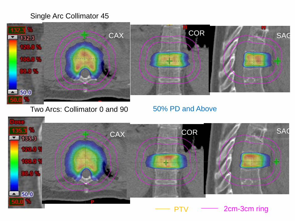
Single Arc Collimator 45
Two Arcs: Collimator 0 and 90 50% PD and Above
PTV 2cm-3cm ring
CAX
CAX
COR
COR
SAG
SAG

Single Arc Collimator 45
Two Arcs: Collimator 0 and 90
Additional 15 cc volume of normal tissue receiving 5% PD
5% PD and Above
PTV 2cm-3cm ring
CAX
CAX
COR
COR
SAG
SAG

Jaw opening area twice as muchWhen compared to collimatorAt 0 or 90.
More leakage dose inSuperior and inferior beyond PTV.
Leaves parked inside jaws when Unused for RapidArc
Coll 45
Coll 0Coll 90

Fixed IMRT Fields100% PD and above 50% PD and above
25% PD and above 12.5% PD and above
11 fixed field IMRT
Can meet similar R50% and D2cmconstraints
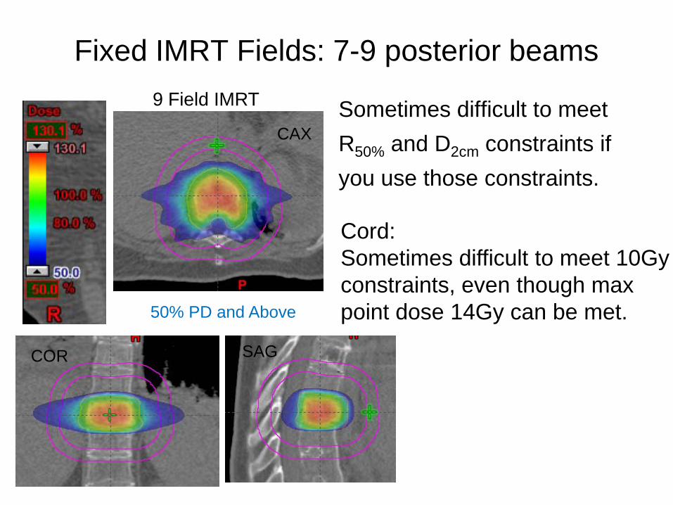
Fixed IMRT Fields: 7-9 posterior beams
Sometimes difficult to meetR50% and D2cm constraints ifyou use those constraints.
9 Field IMRT
Cord:Sometimes difficult to meet 10Gy constraints, even though maxpoint dose 14Gy can be met.50% PD and Above
CAX
COR SAG
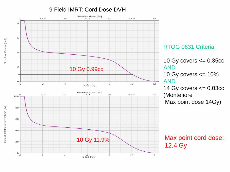
RTOG 0631 Criteria:
10 Gy covers <= 0.35ccAND10 Gy covers <= 10%AND14 Gy covers <= 0.03cc(MontefioreMax point dose 14Gy)
10 Gy 11.9%
10 Gy 0.99cc
Max point cord dose:12.4 Gy
9 Field IMRT: Cord Dose DVH
Montefiore-Einstein Cancer Center SBRT Registry Study
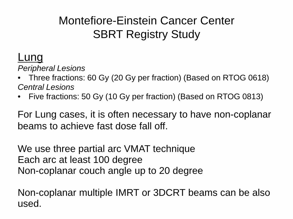
LungPeripheral Lesions• Three fractions: 60 Gy (20 Gy per fraction) (Based on RTOG 0618)Central Lesions• Five fractions: 50 Gy (10 Gy per fraction) (Based on RTOG 0813)
For Lung cases, it is often necessary to have non-coplanar beams to achieve fast dose fall off.
We use three partial arc VMAT techniqueEach arc at least 100 degreeNon-coplanar couch angle up to 20 degree
Non-coplanar multiple IMRT or 3DCRT beams can be alsoused.

Arc1: Couch 0, Gantry 179-30
Arc2: Couch 15, Gantry 330-110
Arc3: Couch 345, Gantry 110-330
Arc 2 and Arc 3 are mostly anterior arcs to gain clearance
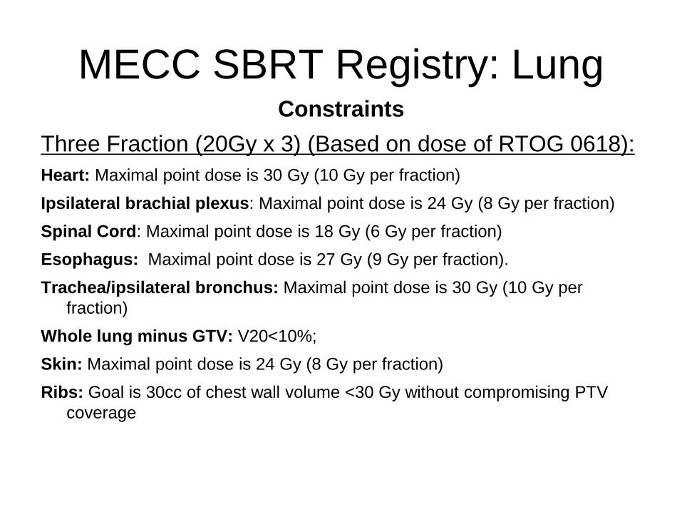
MECC SBRT Registry: LungConstraints
Three Fraction (20Gy x 3) (Based on dose of RTOG 0618):Heart: Maximal point dose is 30 Gy (10 Gy per fraction)Ipsilateral brachial plexus: Maximal point dose is 24 Gy (8 Gy per fraction)Spinal Cord: Maximal point dose is 18 Gy (6 Gy per fraction) Esophagus: Maximal point dose is 27 Gy (9 Gy per fraction). Trachea/ipsilateral bronchus: Maximal point dose is 30 Gy (10 Gy per
fraction)Whole lung minus GTV: V20<10%;Skin: Maximal point dose is 24 Gy (8 Gy per fraction)Ribs: Goal is 30cc of chest wall volume <30 Gy without compromising PTV
coverage

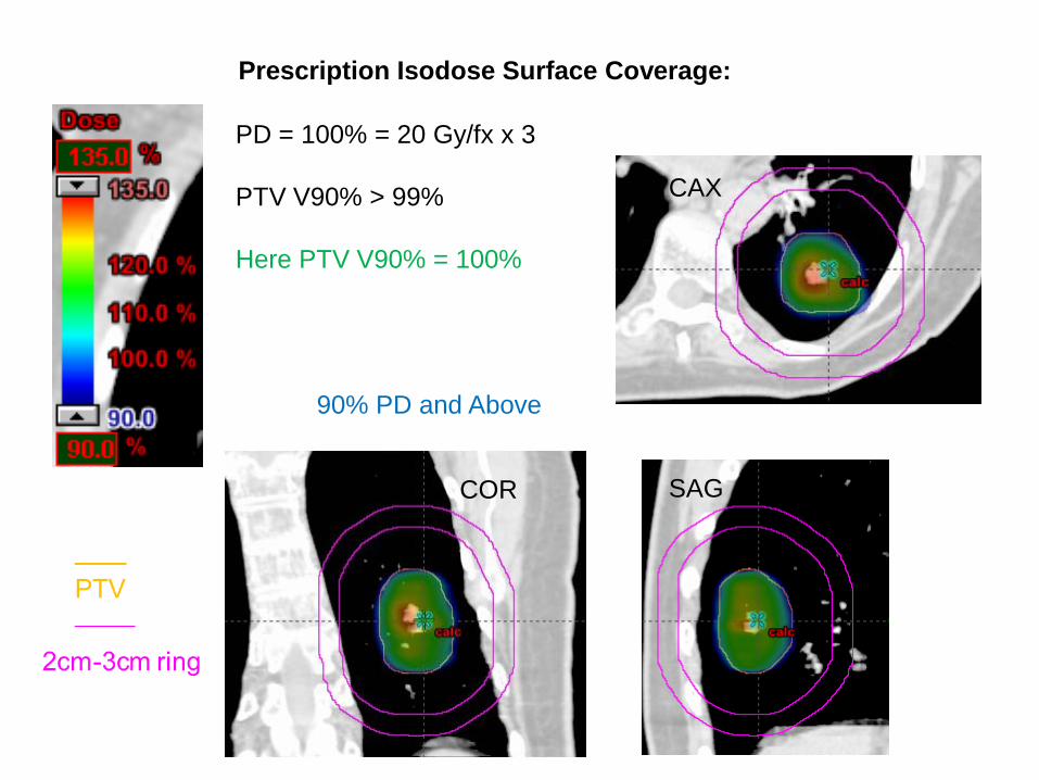
Prescription Isodose Surface Coverage:
PD = 100% = 20 Gy/fx x 3
PTV V100 = 95%
PTV V100 = 95%
CAX
CorSag
100% PD and Above
CAX
COR SAG
Prescription Isodose Surface Coverage:
PD = 100% = 20 Gy/fx x 3
PTV V90% > 99%
Here PTV V90% = 100%
90% PD and Above
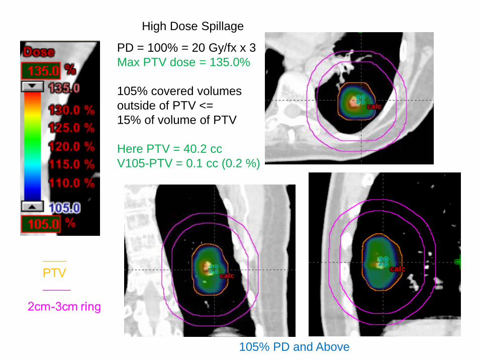
High Dose Spillage
PD = 100% = 20 Gy/fx x 3Max PTV dose = 135.0%
105% covered volumes outside of PTV <= 15% of volume of PTV
Here PTV = 40.2 ccV105-PTV = 0.1 cc (0.2 %)
105% PD and Above

CAX
COR SAG
Conformality : Prescription Dose Volume vs. PTV Volume
PD = 100% = 20 Gy/fx x 3
V100 / PTV volume <= 1.2
Here PTV = 40.2 ccV100 = 41.0 ccRatio = 1.02
100% PD and Above

CAX
COR SAG
Intermediate Dose Spillage: R50% and D2cm
For PTV = 40.2 ccR50% <= 4.2; D2cm = 59.6%
Here V50% = 169.5 ccR50% = 4.2D2cm = 52.6%
50% PD and Above

25% isodose restricted mainly in the ipsilateral lung
25% PD and Above
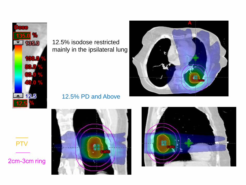
12.5% isodose restricted mainly in the ipsilateral lung
12.5% PD and Above
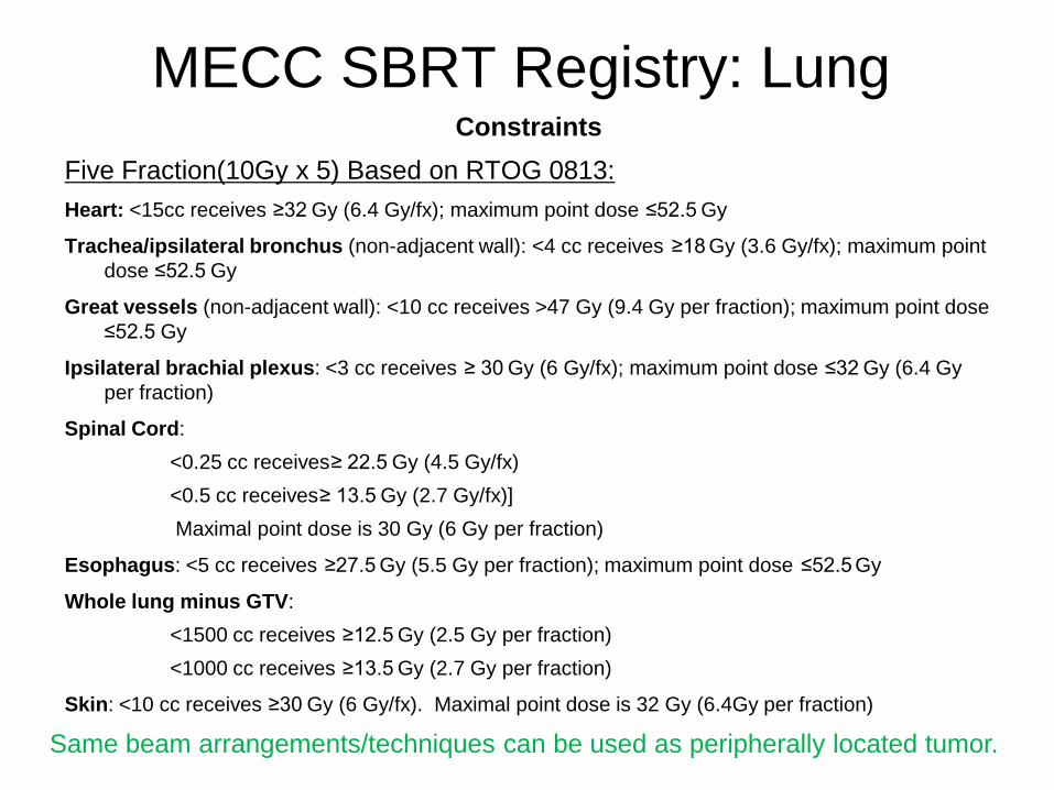
MECC SBRT Registry: LungConstraints
Five Fraction(10Gy x 5) Based on RTOG 0813: Heart: <15cc receives ≥32 Gy (6.4 Gy/fx); maximum point dose ≤52.5 Gy
Trachea/ipsilateral bronchus (non-adjacent wall): <4 cc receives ≥18 Gy (3.6 Gy/fx); maximum point dose ≤52.5 Gy
Great vessels (non-adjacent wall): <10 cc receives >47 Gy (9.4 Gy per fraction); maximum point dose ≤52.5 Gy
Ipsilateral brachial plexus: <3 cc receives ≥ 30 Gy (6 Gy/fx); maximum point dose ≤32 Gy (6.4 Gyper fraction)
Spinal Cord: <0.25 cc receives≥ 22.5 Gy (4.5 Gy/fx)<0.5 cc receives≥ 13.5 Gy (2.7 Gy/fx)]Maximal point dose is 30 Gy (6 Gy per fraction)
Esophagus: <5 cc receives ≥27.5 Gy (5.5 Gy per fraction); maximum point dose ≤52.5 Gy
Whole lung minus GTV:<1500 cc receives ≥12.5 Gy (2.5 Gy per fraction)<1000 cc receives ≥13.5 Gy (2.7 Gy per fraction)
Skin: <10 cc receives ≥30 Gy (6 Gy/fx). Maximal point dose is 32 Gy (6.4Gy per fraction)
Same beam arrangements/techniques can be used as peripherally located tumor.

Montefiore-Einstein Cancer Center SBRT Registry Study
LiverMetastasisIf lesions > 2cm from Porta Hepatis/Bile Duct: Three Fractions 20Gy x 3If lesions ≤ 2cm from Porta Hepatis/Bile Duct: Five Fractions 10Gy x 5
HCC• Five fractions: 30-50 Gy (depends on Veff)• Veff Dose per fraction
< 0.3 10 Gy x 5 0.3 - 0.4 9 Gy x 5 0.4 - 0.5 8 Gy x 50.5 - 0.6 6 Gy x 5
Dawson LA et al Acta Oncol 45:856, 2006
Same beam arrangements/techniques can be used as lung SBRT.

ConstraintsMetastasisIf lesions > 2cm from Porta Hepatis/Bile Duct: Three Fractions 20Gy x 3If lesions ≤ 2cm from Porta Hepatis/Bile Duct: Five Fractions 10Gy x 5Liver minus-GTV: >700mL receive <15 Gy Heart: <15cc receives ≥32 Gy; maximum point dose ≤52.5 GyLung: <1000 cc receives ≥11.4 Gy (3.8 Gy/fx)Esophagus: Maximal point dose is 27 Gy (9 Gy per fraction)Stomach/Duodenum/Small Bowel: Maximal point dose 30 GyKidney: ≤1/3 volume (sum of left and right) receives ≥15 Gy; V6 < 10%Colon/Rectum: Maximal dose 34 Gy to 0.5 ccSpinal Cord: Maximal point dose is 18 Gy (6 Gy per fraction) Skin: Maximal point dose is 24 Gy (8 Gy per fraction)
MECC SBRT Registry: Liver
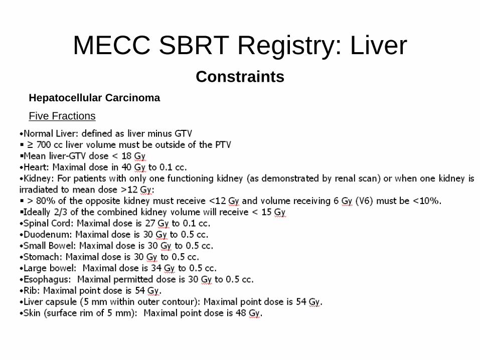
ConstraintsHepatocellular CarcinomaFive Fractions
MECC SBRT Registry: Liver

Stereotactic body radiation therapy: The report of AAPM Task Group 101
Stanley H. Benedict et alMed. Phys. 37 (8), August 2010
Detailed information about SBRT

SBRT CT simulation
• For upper thoracic regions, both arms (elbows) should be over the patient’s head and included in the CT scan so that clearance of beams can be visualized during planning.
• Scan 15 cm beyond field borders (sometimes non-coplanar beams are needed).
• For spine cases, include sacrum for lower spine or include C1 for upper spine so that vertebrae can be easily identified.

SBRT C-Spine• CT scan has to include C1• Setup uncertainty large due to flexibility in neck
area• Fusion with MRI might be difficult because of
different neck position• 2-3mm margin should be added for PTV• Hypofractionation preferred instead of single
fraction – unless significant cord clearance• We use BlueBAGTM with vacuum suction plus
head and neck mask as immobilization device
SBRT T-Spine
• CT scan has to either include C1 or L Spine
• Arms on the side preferred so that patient can stay comfortable
• Beams avoid arms• We use BlueBAGTM with vacuum suction
as immobilization device

SBRT L-Spine
• CT has to include Sacrum• Arms on chest instead of up for comfort• We use BlueBAGTM with vacuum suction
as immobilization device
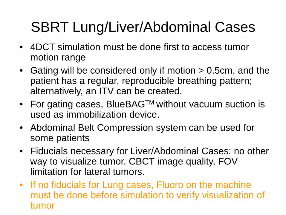
SBRT Lung/Liver/Abdominal Cases• 4DCT simulation must be done first to access tumor
motion range• Gating will be considered only if motion > 0.5cm, and the
patient has a regular, reproducible breathing pattern; alternatively, an ITV can be created.
• For gating cases, BlueBAGTM without vacuum suction is used as immobilization device.
• Abdominal Belt Compression system can be used for some patients
• Fiducials necessary for Liver/Abdominal Cases: no other way to visualize tumor. CBCT image quality, FOV limitation for lateral tumors.
• If no fiducials for Lung cases, Fluoro on the machine must be done before simulation to verify visualization of tumor
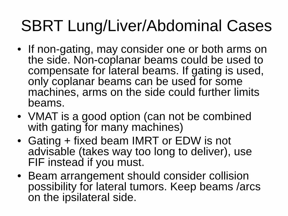
• If non-gating, may consider one or both arms on the side. Non-coplanar beams could be used to compensate for lateral beams. If gating is used, only coplanar beams can be used for some machines, arms on the side could further limits beams.
• VMAT is a good option (can not be combined with gating for many machines)
• Gating + fixed beam IMRT or EDW is not advisable (takes way too long to deliver), use FIF instead if you must.
• Beam arrangement should consider collision possibility for lateral tumors. Keep beams /arcs on the ipsilateral side.
SBRT Lung/Liver/Abdominal Cases

• If no fiducials, create fluoro beam aperture that hugs GTV.
• If there is fiducials, create fluoro beam aperture that use fiducials as corners.
• CBCT alignment with GTV, bony landmark secondary but should be less than 1cm discrepancy. Otherwise, reposition patient.
• CBCT sometimes do not align well with average sim CT due to breathing variation
• Fluoro to verify positioning after CBCT.• Fluoro between fields to monitor setup
consistency.
SBRT Lung/Liver/Abdominal Cases
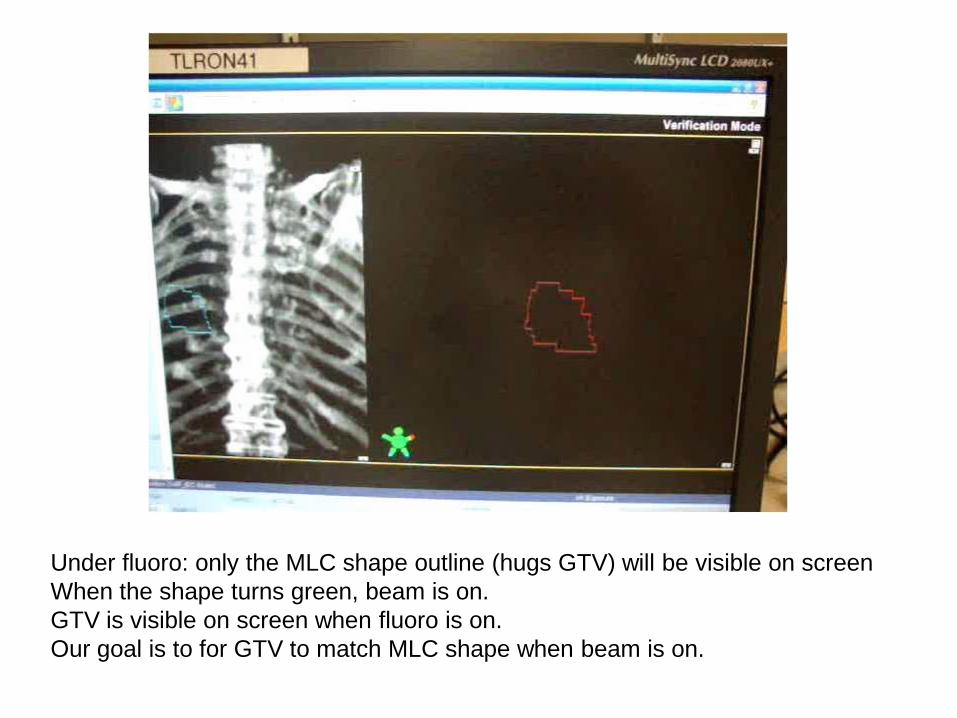
Under fluoro: only the MLC shape outline (hugs GTV) will be visible on screenWhen the shape turns green, beam is on.GTV is visible on screen when fluoro is on. Our goal is to for GTV to match MLC shape when beam is on.
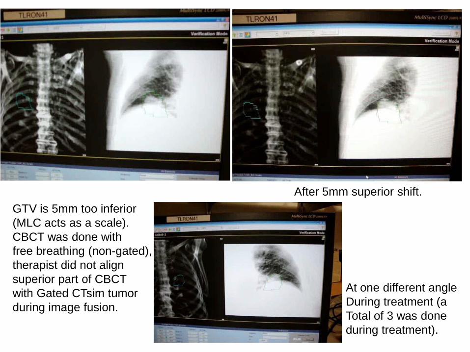
GTV is 5mm too inferior(MLC acts as a scale).CBCT was done with free breathing (non-gated),therapist did not alignsuperior part of CBCT with Gated CTsim tumorduring image fusion.
After 5mm superior shift.
At one different angleDuring treatment (a Total of 3 was done during treatment).

Bottom line for SBRT
• Without an approved plan in the patient’s chart, no treatment verification can be done. Physics must be present for treatment verification.
• If IMRT, without IMRT QA documented, no 1st treatment should be done.
• Attending must be present for every treatment fraction. Physics should be available for every treatment.

What is a ‘Dry Run’?• Treatment verification
– Reproduce setup– Verify isocenter– Clinically mode up each treatment fieldCheck beam clearance (collision)Check any interlock
MLC interlock? Reinitialized but can not clear means corruption of MLC files undeliverable beam
Potential MU problem? For example > 1000 for any single field beyond machine capability for non-SRS beams
Clearly mark immobilization devices after successful dry run.

Summary
• RTOG protocols are useful guidelines for treatment planning for SBRT
• SBRT procedures from CT simulation to treatment planning to treatment verification and treatment warrant serious attention from everyone involved. Establishing clear protocols for your own institution is necessary for the safe delivery of SBRT.

Acknowledgements• Physics
Jin ShenJoe LeeAleiya GafaPaola Godoy-ScripesJack KesselDinesh MynampatiKuo, Hsiang-ChiRavindra YaparpalviWolfgang Tome
• PhysiciansWilliam BodnerMadhur GargJana FoxMaury RosensteinKeyur MehtaChandan GuhaShalom Kalnicki

Thank You