saw vise hardware kit
DESCRIPTION
ÂTRANSCRIPT

Copyright© 2015 Texas Heritage Woodworks Page 1
Saw Vise Hardware Kit
Thank you for purchasing our Saw Vise Hardware Kit! This kit was designed around the proven Wing Nut assembly used in our Moxon Vise Kits. The saw vise can be built to fit your needs. The dimensions in these instructions will build a saw vise that has 18” wide jaws. It is designed to clamp onto a workbench that is 33.5” tall. I am 5’ 11” tall and this saw vise brings the saw teeth up to a comfortable position for me. The dimensions can be modified to fit you and your particular setup.
Visit http://www.txheritage.net/sawvise for more info!

Copyright© 2015 Texas Heritage Woodworks Page 2
Saw Vise Hardware Components
Your new Saw Vise Hardware kit consists of
- (1) Acme Threaded Post
- (1) Wing Nut
- (1) Extra Thick Washer
- (2) #8 Screws
- (2) ¼-20 Brass Threaded Inserts
- (2) ¼-20 socket cap screws, 2 ¾” long
- (2) Hinge Leather 1”x4”
- (2) Jaw Leather 1”x18”
The metal components come unfinished and have a light coat of oil on them to prevent corrosion. A corrosion inhibitor has also been added to the package for further protection. There are a few options for finishing the metal hardware. The simplest is to just leave them as is. Occasionally refreshing the oil finish, or adding light coats of paste wax will keep the metal components rust free. If a different finish is desired, the hardware needs to be thoroughly cleaned to remove any oil residue prior to finishing. A coat of beeswax or paraffin wax can be added to the screws occasionally to make everything work smoothly.

Copyright© 2015 Texas Heritage Woodworks Page 3
Materials Needed
Choose material that is free of knots and defects. Quartersawn or Riftsawn material with straight grain will work best, the stress produced by the Acme thread can be substantial.
The front leg is 1 ½” thick, 4” wide, 21” long. It is the part of the saw vise gets secured to the bench, either by a face vise or with holdfasts or clamps. The rear leg is 1 ½” thick, 4” wide, and 13” long. It rests on the benchtop, establishing the working height of the saw vise. If you decide to modify the height of the saw vise, this is the component that needs to be addressed.
Both jaws are 2” thick, 4” wide, and 18” long, they are made from a single piece of wood that is 8” wide. Each jaw is attached to the leg by means of a drawbored mortise and tenon joint. A 5/8” dowel is used for the drawbore pin. This joinery is exceptionally strong and is a good choice for this application. The hinge is constructed from a piece of wood that is 1/2”x1”x4”.
The hinge block is just a piece of hardwood that is 3 ¾” long, 1” tall, and ½” thick

Copyright© 2015 Texas Heritage Woodworks Page 4
Jaw Construction
Only the top 1” of each jaw contacts the saw. The rest of the jaw below that portion has been removed to allow clearance for backsaws. To remove this portion, I recommend using a stacked dado blade on the table saw. Make your first cut with the fence set at 1” away from the blade, and the blade set at ¼” high. Make your first pass, then flip the wood over and make a second pass on the opposite side. Move the fence a little further from the blade and repeat the cut. Keep doing this until you meet in the middle. Your piece should look similar to this when finished.
Find and mark the exact center line of the jaw stock. Rip along the line on the table saw to separate the two jaws from each other. At this time it is a good idea to determine which jaw will be the front and which will be the rear. Mark the jaws and the corresponding legs. This will insure that you don’t get them mixed up while fine tuning the mortise and tenon joint.

Copyright© 2015 Texas Heritage Woodworks Page 5
On the bottom of each jaw cut a mortise that is 5/8” wide, 3” long, and 2” deep, centered on the jaw. The tenon on the leg will be cut later. In order to make room for saw handles, some material needs to be removed from the lower corners of the jaws. By placing each of your handsaws on the jaw blanks, you can see how each handle may interfere. Play around a bit and come up with a shape that is effective and appealing.
In order to make sharpening easier, material needs to be removed from the back of each jaw as well. This will give you better access to the saw teeth while filing. Using two chamfers instead of one will leave more material on the jaw, resulting in a stronger jaw. I like to start the first chamfer around ¼” from the working face of the jaw, with the second chamfer ending at the midpoint of the jaw.

Copyright© 2015 Texas Heritage Woodworks Page 6
While this layout may look complicated, it can be achieved through use of a drill press and bandsaw. Use the drill press with a forstner bit to establish the smaller curve in the jaw. While at the drill press, use a 5/8” drill bit and drill a hole that is 1” above the bottom of the jaws, centered side to side. Inserting a sacrificial piece of wood into the mortise will keep blowout to a minimum while drilling. This is for the drawbore pin.
By utilizing the tilting table on a bandsaw, the back material on the jaws can be removed. Then use the bandsaw to remove the rest of the material on the lower portion of the jaw. Clean up all of the mill marks with a handplane, rasps, files, and sandpaper and your jaws should look something like this.

Copyright© 2015 Texas Heritage Woodworks Page 7
Legs
Cut a matching tenon on each respective leg, making sure you have a nice fit. Sloppy joinery here will result in premature failure, take your time. Once the joints are nice and tight, transfer the outline of the hole onto the tenons. Remove the jaw and drill the 5/8” hole in each tenon, moving it towards the shoulder approximately 1/32”. This offset will keep the jaw mated firmly to the leg once the drawbore pin is hammered home.
To drill the hole for the threaded rod in the legs, mark down 3” from the shoulder of the tenon, centered on the leg. In order to keep the holes aligned, clamp both legs together while drilling the hole with a 5/8” bit.

Copyright© 2015 Texas Heritage Woodworks Page 8
It is now time to mount the threaded rod to the rear leg. Using a countersink in the hole prior to inserting the threaded rod will provide clearance for the weld, making it easier to mark around the plate.
Use a square to align the plate and mark the perimeter with a marking knife or sharp pencil. A shallow mortise needs to be cut to house the mounting plate. This not only provides a strong mechanical support, it also is aesthetically pleasing. I prefer using a chisel and router plane to make the 1/8” deep mortise. Once the mortise is cut, mark the holes for the #8 screws and drill pilot holes with a 1/8”” bit. Some wax or soap on the threads will make the screws go in easier.
Copyright© 2015 Texas Heritage Woodworks Page 9
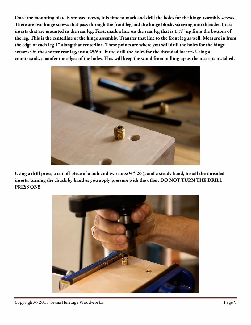
Once the mounting plate is screwed down, it is time to mark and drill the holes for the hinge assembly screws. There are two hinge screws that pass through the front leg and the hinge block, screwing into threaded brass inserts that are mounted in the rear leg. First, mark a line on the rear leg that is 1 ½” up from the bottom of the leg. This is the centerline of the hinge assembly. Transfer that line to the front leg as well. Measure in from the edge of each leg 1” along that centerline. These points are where you will drill the holes for the hinge screws. On the shorter rear leg, use a 25/64” bit to drill the holes for the threaded inserts. Using a countersink, chamfer the edges of the holes. This will keep the wood from pulling up as the insert is installed.
Using a drill press, a cut off piece of a bolt and two nuts(¼”-20 ), and a steady hand, install the threaded inserts, turning the chuck by hand as you apply pressure with the other. DO NOT TURN THE DRILL PRESS ON!!

Copyright© 2015 Texas Heritage Woodworks Page 10
Drill the holes through the front leg, using a 9/32” drill bit. Transfer those hole positions to the hinge block and drill those out as well.
Drawbore
Before joining the jaws and the legs together, take this time to add chamfers or other decorative details to the legs. It will be much easier with the jaw out of the way.
Cut two 5/8” dowels to approximately 2 ½” in length. Use a chisel to lightly taper one end, this will allow the dowel to pass through the joint with less trouble. Apply a liberal amount of glue to the mortise on each jaw. Insert the appropriate leg, apply a little glue into the hole for the drawbore pin, the line up the pin and hammer it home.
Copyright© 2015 Texas Heritage Woodworks Page 11
Compound Spring Joint
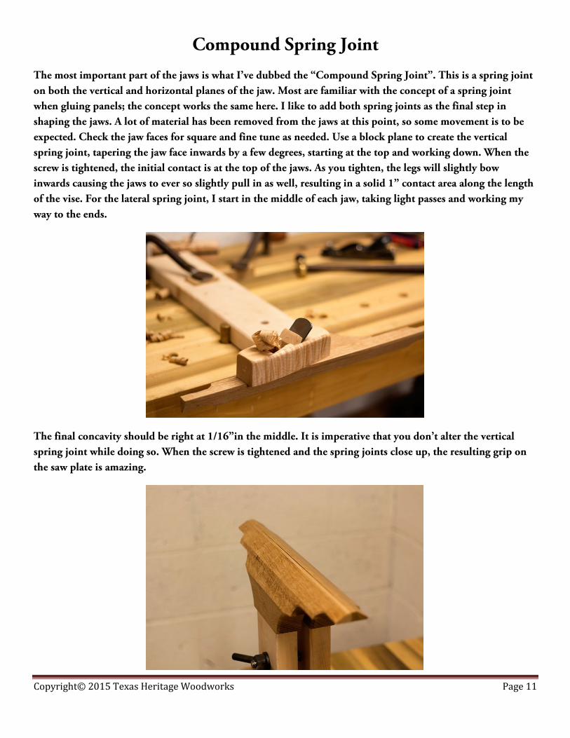
The most important part of the jaws is what I’ve dubbed the “Compound Spring Joint”. This is a spring joint on both the vertical and horizontal planes of the jaw. Most are familiar with the concept of a spring joint when gluing panels; the concept works the same here. I like to add both spring joints as the final step in shaping the jaws. A lot of material has been removed from the jaws at this point, so some movement is to be expected. Check the jaw faces for square and fine tune as needed. Use a block plane to create the vertical spring joint, tapering the jaw face inwards by a few degrees, starting at the top and working down. When the screw is tightened, the initial contact is at the top of the jaws. As you tighten, the legs will slightly bow inwards causing the jaws to ever so slightly pull in as well, resulting in a solid 1” contact area along the length of the vise. For the lateral spring joint, I start in the middle of each jaw, taking light passes and working my way to the ends.
The final concavity should be right at 1/16”in the middle. It is imperative that you don’t alter the vertical spring joint while doing so. When the screw is tightened and the spring joints close up, the resulting grip on the saw plate is amazing.

Copyright© 2015 Texas Heritage Woodworks Page 12
Leather
I recommend hide glue for gluing the leather, though any wood glue or contact cement will work. Before adhering the leather to the hinge block, make sure you transfer and cut the holes for the hinge screws. Due to the complexity of the jaw assemblies, traditional clamping methods really don’t work that well. Instead, use a more modern approach. Plastic wrap makes a great clamp when not a lot of pressure is needed. It can conform to almost any shape and it can be pulled tight as it is wrapped around, providing just the right amount of clamping pressure. Once the glue dries, use a sharp knife or chisel to trim off any excess leather.
Copyright© 2015 Texas Heritage Woodworks Page 13
Final Assembly and Use
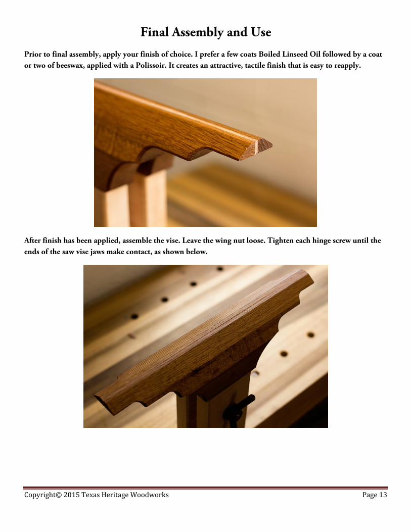
Prior to final assembly, apply your finish of choice. I prefer a few coats Boiled Linseed Oil followed by a coat or two of beeswax, applied with a Polissoir. It creates an attractive, tactile finish that is easy to reapply.
After finish has been applied, assemble the vise. Leave the wing nut loose. Tighten each hinge screw until the ends of the saw vise jaws make contact, as shown below.

Copyright© 2015 Texas Heritage Woodworks Page 14
Using your fingers on the inside of the jaws, gently pry the jaws open and insert a saw. The goal is to adjust the tension on the jaws until a saw can be supported by the hinge tension alone. This makes it easier to adjust the saw prior to sharpening. You have the ability to move the saw in small increments without it slipping or falling.
Once the jaws have been tuned, tighten down on the wing nut. The saw should be held tightly, with full 1” contact along the entire saw plate. You can now proceed to sharpening!

Copyright© 2015 Texas Heritage Woodworks Page 15