satop_rfc4553
DESCRIPTION
Summary about RFC 4553Structure-Agnostic Time Division Multiplexing (TDM) over Packet (SAToP)TRANSCRIPT

SAToPTuan Nguyen-viet
Tuan Nguyen-viet Slide 2
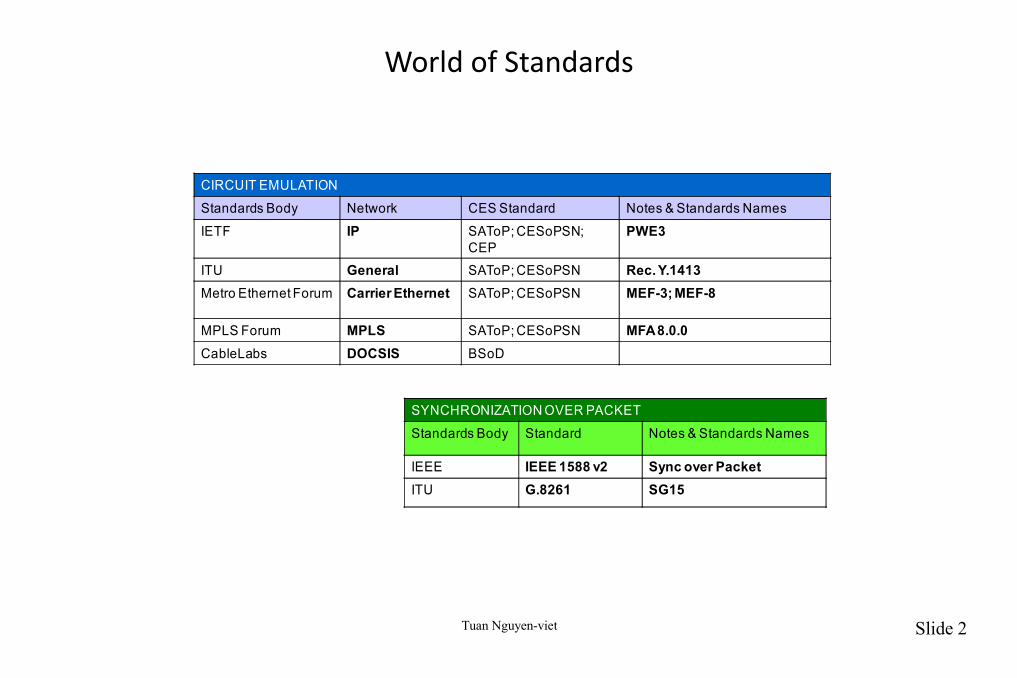
World of Standards
CIRCUIT EMULATION
Standards Body Network CES Standard Notes & Standards Names
IETF IP SAToP; CESoPSN; CEP
PWE3
ITU General SAToP; CESoPSN Rec. Y.1413Metro Ethernet Forum Carrier Ethernet SAToP; CESoPSN MEF-3; MEF-8
MPLS Forum MPLS SAToP; CESoPSN MFA 8.0.0CableLabs DOCSIS BSoD
SYNCHRONIZATION OVER PACKET
Standards Body Standard Notes & Standards Names
IEEE IEEE 1588 v2 Sync over PacketITU G.8261 SG15
Tuan Nguyen-viet Slide 3
Part 1: IETF RFC4553
Tuan Nguyen-viet Slide 4
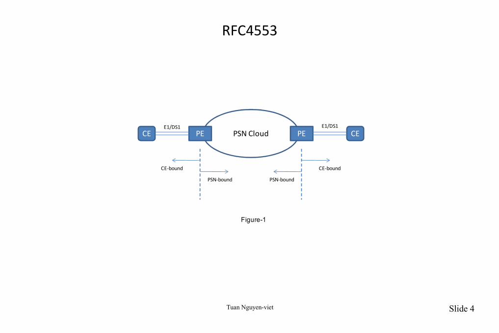
RFC4553
PSN CloudPE PECE CE
PSN-bound
CE-bound
E1/DS1 E1/DS1
PSN-bound
CE-bound
Figure-1

Tuan Nguyen-viet Slide 5
SAToP Chronology
• SAToP:
– Structure-Agnostic Time Division Multiplexing (TDM) over Packet (SAToP):
● The synchronous bit stream is segmented
● TDM or Sonet frames may be adapted, but are not compressed
● Control word is appended with timing and sequencing information
● Outer and inner labels are appended
● Packets are transported over MPLS network to destination
● MPLS labels are stripped
● Control word is checked, utilized and stripped
● TDM is extracted and played out
Tuan Nguyen-viet Slide 6
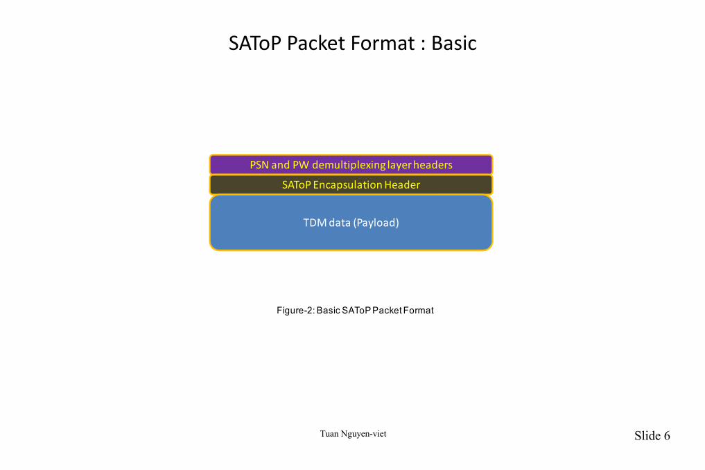
SAToP Packet Format : Basic
PSN and PW demultiplexing layer headers
SAToP Encapsulation Header
TDM data (Payload)
Figure-2: Basic SAToP Packet Format

Tuan Nguyen-viet Slide 7
SAToP Packet Format :PSN and PW De-multiplexing Layer Headers
• Both UDP and L2TPv3 (RFC3931) can provide the PW de-multiplexing mechanisms for SAToP PWs over an IPv4/IPv6 PSN.
• The PW label provides the de-multiplexing function for an MPLS PSN as described in Section 5.4.2 of the RFC3985.
• The total size of a SAToP packet for a specific PW must not exceed path MTU (Maximum Transmission Unit) between the pair of PEs terminating this PW.
• SAToP implementations using IPv4 PSN must mark the IPv4 datagrams they generate as "Don’t Fragment“ (see the RFC791 and also the PWE3-FRAG).
Tuan Nguyen-viet Slide 8
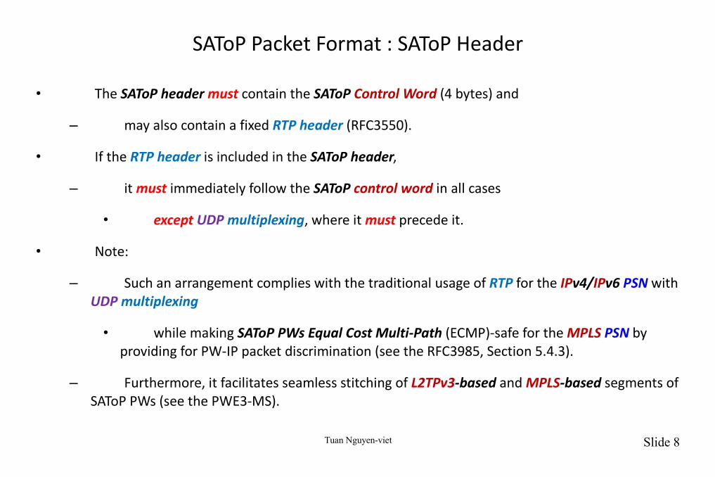
SAToP Packet Format : SAToP Header
• The SAToP header must contain the SAToP Control Word (4 bytes) and
– may also contain a fixed RTP header (RFC3550).
• If the RTP header is included in the SAToP header,
– it must immediately follow the SAToP control word in all cases
• except UDP multiplexing, where it must precede it.
• Note:
– Such an arrangement complies with the traditional usage of RTP for the IPv4/IPv6 PSN with UDP multiplexing
• while making SAToP PWs Equal Cost Multi-Path (ECMP)-safe for the MPLS PSN by providing for PW-IP packet discrimination (see the RFC3985, Section 5.4.3).
– Furthermore, it facilitates seamless stitching of L2TPv3-based and MPLS-based segments of SAToP PWs (see the PWE3-MS).
Tuan Nguyen-viet Slide 9
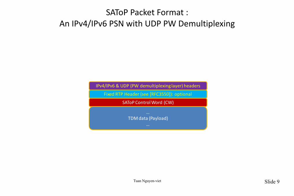
SAToP Packet Format :An IPv4/IPv6 PSN with UDP PW Demultiplexing
IPv4/IPv6 & UDP (PW demultiplexing layer) headers
Fixed RTP Header (see [RFC3550]): optional
SAToP Control Word (CW)
…TDM data (Payload)
…
Tuan Nguyen-viet Slide 10
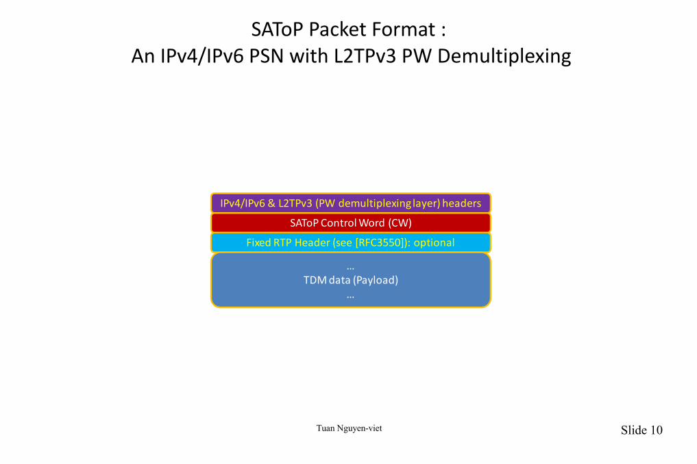
SAToP Packet Format : An IPv4/IPv6 PSN with L2TPv3 PW Demultiplexing
IPv4/IPv6 & L2TPv3 (PW demultiplexing layer) headers
Fixed RTP Header (see [RFC3550]): optional
SAToP Control Word (CW)
…TDM data (Payload)
…
Tuan Nguyen-viet Slide 11
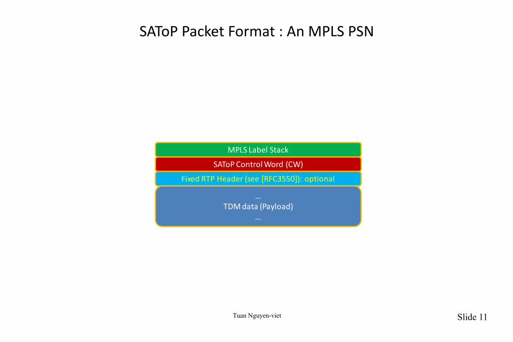
SAToP Packet Format : An MPLS PSN
MPLS Label Stack
SAToP Control Word (CW)
Fixed RTP Header (see [RFC3550]): optional
…TDM data (Payload)
…
Tuan Nguyen-viet Slide 12
Usage and Structure of the Control Word (CW)
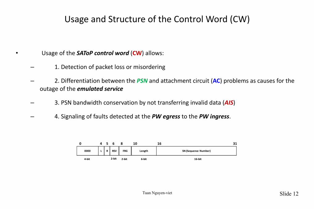
• Usage of the SAToP control word (CW) allows:
– 1. Detection of packet loss or misordering
– 2. Differentiation between the PSN and attachment circuit (AC) problems as causes for the outage of the emulated service
– 3. PSN bandwidth conservation by not transferring invalid data (AIS)
– 4. Signaling of faults detected at the PW egress to the PW ingress.
0000 L R RSV FRG Length SN (Sequence Number)
540 6 8 10 16 31
2-bit 2-bit 6-bit 16-bit4-bit
Tuan Nguyen-viet Slide 13
The structure of the SAToP Control Word (CW)
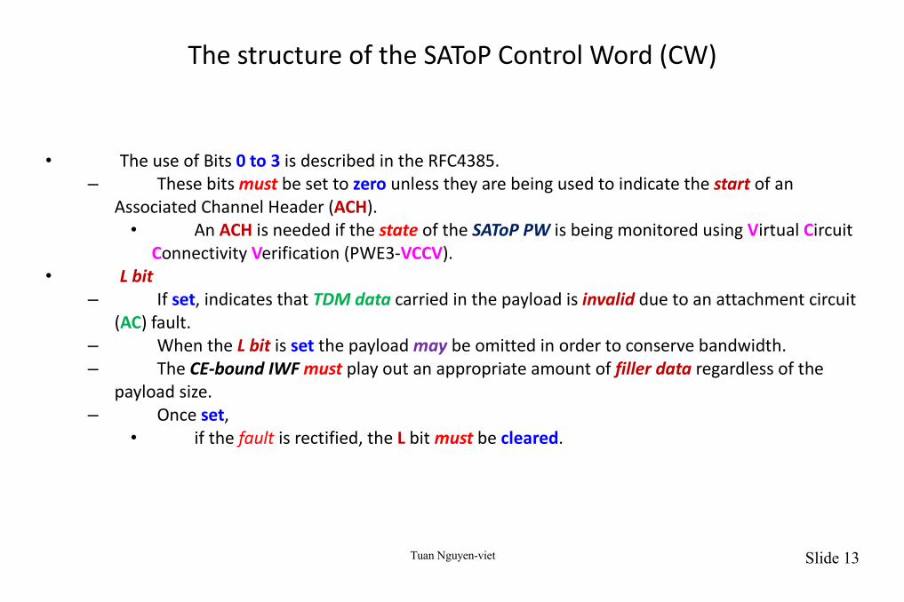
• The use of Bits 0 to 3 is described in the RFC4385.– These bits must be set to zero unless they are being used to indicate the start of an
Associated Channel Header (ACH).• An ACH is needed if the state of the SAToP PW is being monitored using Virtual Circuit
Connectivity Verification (PWE3-VCCV).• L bit
– If set, indicates that TDM data carried in the payload is invalid due to an attachment circuit (AC) fault.
– When the L bit is set the payload may be omitted in order to conserve bandwidth.– The CE-bound IWF must play out an appropriate amount of filler data regardless of the
payload size.– Once set,
• if the fault is rectified, the L bit must be cleared.

Tuan Nguyen-viet Slide 14
The structure of the SAToP Control Word (2)
• Note:– This document does not specify which TDM fault conditions are treated as invalidating the
data carried in the SAToP packets.– Possible examples include, but are not limited to, LOS and AIS.
• R bit– If set by the PSN-bound IWF, indicates that its local CE-bound IWF is in the packet loss
state, i.e., has lost a preconfigured number of consecutive packets.– The R bit must be cleared by the PSN-bound IWF once its local CE-bound IWF has exited
the packet loss state, i.e., has received a preconfigured number of consecutive packets.• RSV and FRG (bits 6 to 9)
– Must be set to 0 by the PSN-bound IWF and must be ignored by the CE-bound IWF.– RSV is reserved.– FRG is fragmentation; see (PWE3-FRAG).
Tuan Nguyen-viet Slide 15
The structure of the SAToP Control Word (3)
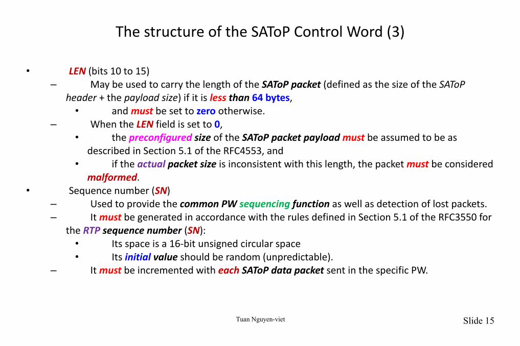
• LEN (bits 10 to 15)– May be used to carry the length of the SAToP packet (defined as the size of the SAToP
header + the payload size) if it is less than 64 bytes, • and must be set to zero otherwise.
– When the LEN field is set to 0,• the preconfigured size of the SAToP packet payload must be assumed to be as
described in Section 5.1 of the RFC4553, and• if the actual packet size is inconsistent with this length, the packet must be considered
malformed.• Sequence number (SN)
– Used to provide the common PW sequencing function as well as detection of lost packets.– It must be generated in accordance with the rules defined in Section 5.1 of the RFC3550 for
the RTP sequence number (SN):• Its space is a 16-bit unsigned circular space• Its initial value should be random (unpredictable).
– It must be incremented with each SAToP data packet sent in the specific PW.
Tuan Nguyen-viet Slide 16
Usage of RTP Header
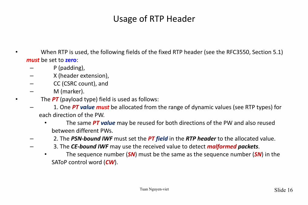
• When RTP is used, the following fields of the fixed RTP header (see the RFC3550, Section 5.1) must be set to zero:
– P (padding),– X (header extension),– CC (CSRC count), and– M (marker).
• The PT (payload type) field is used as follows:– 1. One PT value must be allocated from the range of dynamic values (see RTP types) for
each direction of the PW.• The same PT value may be reused for both directions of the PW and also reused
between different PWs.– 2. The PSN-bound IWF must set the PT field in the RTP header to the allocated value.– 3. The CE-bound IWF may use the received value to detect malformed packets.
• The sequence number (SN) must be the same as the sequence number (SN) in the SAToP control word (CW).
Tuan Nguyen-viet Slide 17
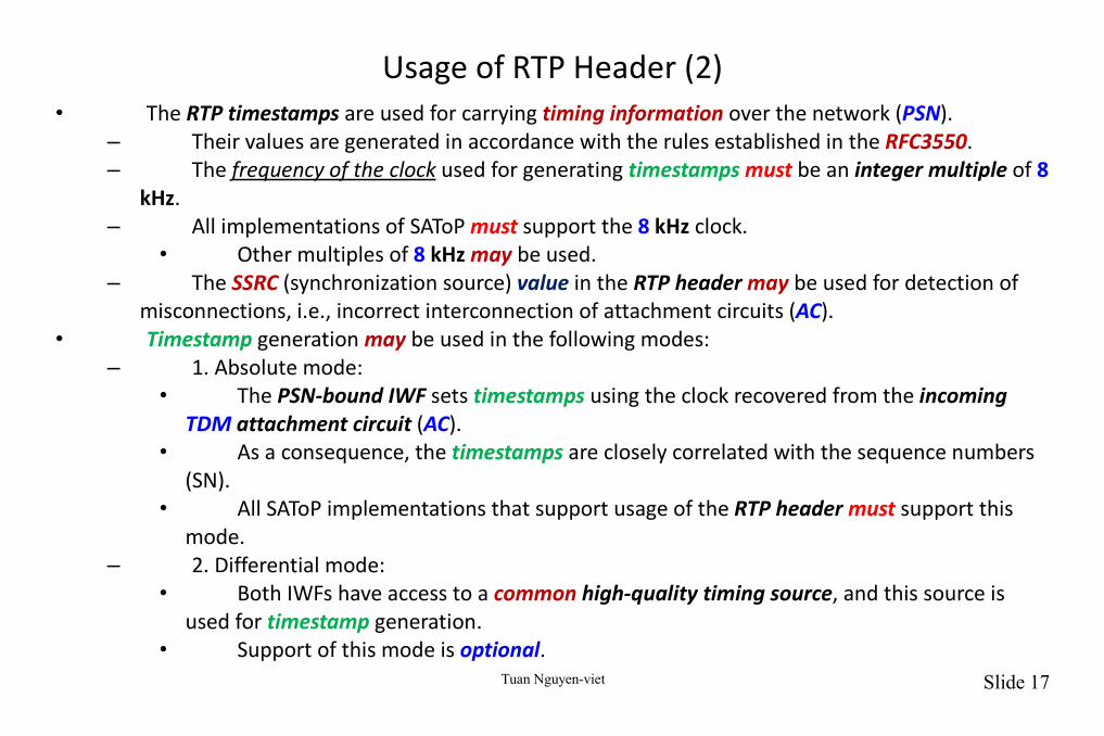
Usage of RTP Header (2)• The RTP timestamps are used for carrying timing information over the network (PSN).
– Their values are generated in accordance with the rules established in the RFC3550.– The frequency of the clock used for generating timestamps must be an integer multiple of 8
kHz.– All implementations of SAToP must support the 8 kHz clock.
• Other multiples of 8 kHz may be used.– The SSRC (synchronization source) value in the RTP header may be used for detection of
misconnections, i.e., incorrect interconnection of attachment circuits (AC).• Timestamp generation may be used in the following modes:
– 1. Absolute mode:• The PSN-bound IWF sets timestamps using the clock recovered from the incoming
TDM attachment circuit (AC).• As a consequence, the timestamps are closely correlated with the sequence numbers
(SN).• All SAToP implementations that support usage of the RTP header must support this
mode.– 2. Differential mode:
• Both IWFs have access to a common high-quality timing source, and this source is used for timestamp generation.
• Support of this mode is optional.
Tuan Nguyen-viet Slide 18
Usage of RTP Header (3)
• Usage of the fixed RTP header in a SAToP PW and all the options associated with its usage (the
timestamping clock frequency, the timestamping mode, selected PT and SSRC values) must be agreed upon between the two SAToP IWFs during PW setup as described in the TDM-Control.
– Other, RTP-specific methods (e.g., see the RFC3551) must not be used.
Tuan Nguyen-viet Slide 19
SAToP Payload Layer
• General Payloads– In order to facilitate handling of packet loss in the PSN,
• all packets belonging to a given SAToP PW are required to carry a fixed number of bytes filled with TDM data received from the attachment circuit (AC).
– The packet payload size • must be defined during the PW setup,• must be the same for both directions of the PW, and• must remain unchanged for the lifetime of the PW.
• The CE-bound and PSN-bound IWFs must agree on SAToP packet payload size during PW setup (default payload size values defined below guarantee that such an agreement is always possible).
– The SAToP packet payload size can be exchanged over the PWE3 control protocol (TDM-Control) by using the Circuit Emulation over Packet (CEP)/TDM Payload Bytes sub-TLV of the Interface Parameters TLV (see the RFC4446).
Tuan Nguyen-viet Slide 20
SAToP Payload Layer (2)
• SAToP uses the following ordering for packetization of the TDM data:– The order of the payload bytes corresponds to their order on the attachment circuit (AC).– Consecutive bits coming from the attachment circuit (AC) fill each payload byte starting
from most significant bit (MSB) to least significant (LSB).• All SAToP implementations must be capable of supporting the following payload sizes:
– E1 = 256 bytes– T1 = 192 bytes– E3 or DS3 = 1024 bytes.
• Notes:– 1. Whatever the selected payload size,
• SAToP does not assume alignment to any underlying structure imposed by TDM framing (byte, frame, or multiframe alignment).
– 2. When the L bit in the SAToP control word (CW) is set,• SAToP packets may omit invalid TDM data in order to conserve PSN bandwidth.
– 3. Payload sizes that are multiples of 47 bytes may be used in conjunction with unstructured ATM-CES (ATM-CES).
Tuan Nguyen-viet Slide 21
Octet-Aligned DS1
• An unstructured DS1 attachment circuit (AC) is sometimes provided already padded to an integer number of bytes, as described in Annex B of the ITU-T G.802.
– This occurs• when the DS1 is de-mapped from a SONET/SDH virtual tributary/container (VT/TU), or• when DS1 is de-framed by a dual-mode E1/DS1 framer.
• In order to facilitate operation in such cases, SAToP defines a special "octet-aligned DS1" transport mode.
– In this mode, the SAToP payload consists of a number of 25-byte subframes,• each subframe carrying 193 bits of TDM data and 7 bits of padding.
Tuan Nguyen-viet Slide 22
Octet-Aligned DS1 (2)
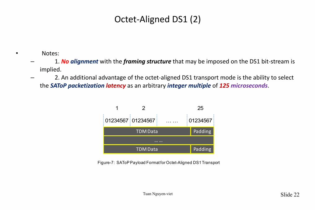
• Notes:– 1. No alignment with the framing structure that may be imposed on the DS1 bit-stream is
implied.– 2. An additional advantage of the octet-aligned DS1 transport mode is the ability to select
the SAToP packetization latency as an arbitrary integer multiple of 125 microseconds.
TDM Data Padding
01234567 01234567 … … 01234567
1 2 25
… …
TDM Data Padding
Figure-7: SAToP Payload Format for Octet-Aligned DS1 Transport

Tuan Nguyen-viet Slide 23
Octet-Aligned DS1 (3)
• Support of the octet-aligned DS1 transport mode is optional.
• An octet-aligned DS1 SAToP PW is not interoperable with a DS1 SAToP PW that carries a non-aligned bit-stream, as described in the previous section.
• Implementations supporting octet-aligned DS1 transport mode must be capable of supporting a payload size of 200 bytes (i.e., a payload of eight 25-byte subframes) corresponding to precisely 1 millisecond of TDM data.
Tuan Nguyen-viet Slide 24
SAToP Operation
• Common Considerations– Edge-to-edge emulation of a TDM service using SAToP is only possible when the two PW
attachment circuits (AC) are of the same type (T1, E1, T3, E3).– The service type is exchanged at PW setup as described in the RFC4447.
Tuan Nguyen-viet Slide 25
IWF Operation: PSN-Bound Direction
• Once the PW is set up, the PSN-bound SAToP IWF operates as follows:– TDM data is packetized using the configured number of payload bytes per packet.– Sequence numbers (SN), flags, and timestamps (if the RTP header is used) are inserted in
the SAToP headers.– SAToP, PW demultiplexing layer, and PSN headers are prepended to the packetized service
data.• The resulting packets are transmitted over the PSN.
Tuan Nguyen-viet Slide 26
IWF Operation: CE-Bound Direction
• The CE-bound SAToP IWF should include a jitter buffer where the payload of the received SAToP packets is stored prior to play-out to the local TDM attachment circuit (AC).
• The size of this buffer should be locally configurable to allow accommodation to the PSN-specific packet delay variation (PDV).
• The CE-bound SAToP IWF should use the sequence number (SN) in the control word (CW) for detection of lost and misordered packets.
• If the RTP header is used, the RTP sequence numbers (SN) may be used for the same purposes.
Tuan Nguyen-viet Slide 27
IWF Operation: CE-Bound Direction(2)• Note:
– With SAToP, a valid sequence number (SN) can be always found in bits 16 - 31 of the first 32-bit word immediately following the PW demultiplexing header regardless of the specific PSN type, multiplexing method, usage or non-usage of the RTP header, etc.
– This approach simplifies implementations supporting multiple encapsulation types as well as implementation of multi-segment (MS) PWs using different encapsulation types in different segments.
• The CE-bound SAToP IWF may reorder misordered packets.– Misordered packets that cannot be reordered must be discarded and treated as lost.– The payload of the received SAToP packets marked with the L bit set should be replaced by
the equivalent amount of the "all ones" pattern even if it has not been omitted.• The payload of each lost SAToP packet must be replaced with the equivalent amount of the
replacement data.– The contents of the replacement data are implementation-specific and may be locally
configurable.– By default, all SAToP implementations must support generation of the "all ones" pattern as
the replacement data.– Before a PW has been set up and after a PW has been torn down, the IWF must play out
the "all ones" pattern to its TDM attachment circuit (AC).
Tuan Nguyen-viet Slide 28
IWF Operation: CE-Bound Direction(3)
• Once the PW has been set up,– the CE-bound IWF begins to receive SAToP packets and to store their payload in the jitter
buffer but continues to play out the "all ones" pattern to its TDM attachment circuit (AC).– This intermediate state persists until a preconfigured amount of TDM data (usually half of
the jitter buffer) has been received in consecutive SAToP packets or until a preconfigured intermediate state timer (started when the PW setup is completed) expires.
• Once the preconfigured amount of the TDM data has been received,– the CE-bound SAToP IWF enters its normal operation state where it continues to receive
SAToP packets and to store their payload in the jitter buffer while playing out the contents of the jitter buffer in accordance with the required clock.
– In this state, the CE-bound IWF performs clock recovery, may monitor PW defects, and may collect PW performance monitoring (PM) data.

Tuan Nguyen-viet Slide 29
IWF Operation: CE-Bound Direction(4)
• If the CE-bound SAToP IWF detects loss of a preconfigured number of consecutive packets– or if the intermediate state timer expires before the required amount of TDM data has
been received, it enters its packet loss state.• While in this state, the local PSN-bound SAToP IWF should mark every packet it
transmits with the R bit set.• The CE-bound SAToP IWF leaves this state and transitions to the normal one once a
preconfigured number of consecutive valid SAToP packets have been received. (Successfully reordered packets contribute to the count of consecutive packets.)
• The CE-bound SAToP IWF must provide an indication of TDM data validity to the CE.– This can be done by transporting or by generating the native AIS indication.– As mentioned above, DS3 AIS cannot be detected or generated by structure-agnostic
means, and• hence a structure-aware NSP must be used when generating a valid AIS pattern.
Tuan Nguyen-viet Slide 30
SAToP Defects
• In addition to the packet loss state of the CE-bound SAToP IWF defined above, it may detect the following defects:
– Stray packets– Malformed packets– Excessive packet loss rate– Buffer overrun– Remote packet loss.
• Corresponding to each defect is a defect state of the IWF,– a detection criterion that triggers transition from the normal operation state to the
appropriate defect state, and– an alarm that may be reported to the management system and thereafter cleared.
• Alarms are only reported when the defect state persists for a preconfigured amount of time (typically 2.5 seconds) and
– must be cleared after the corresponding defect is undetected for a second reconfigured amount of time (typically 10 seconds).
– The trigger and release times for the various alarms may be independent.

Tuan Nguyen-viet Slide 31
SAToP Defects (2)
• Stray packets may be detected by the PSN and PW demultiplexing layers.– When RTP is used, the SSRC field in the RTP header may be used for this purpose as well.– Stray packets must be discarded by the CE-bound IWF, and
• their detection must not affect mechanisms for detection of packet loss.
• Malformed packets are detected by mismatch between• the expected packet size (taking the value of the L bit into account) and• the actual packet size inferred from the PSN and PW demultiplexing layers.
– When RTP is used, lack of correspondence between the PT value and that allocated for this direction of the PW may also be used for this purpose.
– Malformed in-order packets must be discarded by the CE-bound IWF and replacement data generated as with lost packets.
Tuan Nguyen-viet Slide 32
SAToP Defects (3)
• Excessive packet loss rate is detected by computing the average packet loss rate over a configurable amount of times and comparing it with a preconfigured threshold.
• Buffer overrun is detected in the normal operation state when the jitter buffer of the CE-bound IWF cannot accommodate newly arrived SAToP packets.
• Remote packet loss is indicated by reception of packets with their R bit set.
Tuan Nguyen-viet Slide 33
SAToP PW Performance Monitoring (PM)
• Performance monitoring (PM) parameters are routinely collected for TDM services and provide an important maintenance mechanism in TDM networks.
• The ability to collect compatible PM parameters for SAToP PWs enhances their maintenance capabilities.
• Collection of the SAToP PW performance monitoring (PM) parameters is optional and,– if implemented, is only performed after the CE-bound IWF has exited its intermediate
state.

Tuan Nguyen-viet Slide 34
SAToP PW Performance Monitoring (2)
• SAToP defines error events, errored blocks, and defects as follows:– A SAToP error event is defined as insertion of a single replacement packet into the jitter
buffer • (replacement of payload of SAToP packets with the L bit set is not considered insertion
of a replacement packet).– A SAToP errored data block is defined as a block of data played out to the TDM attachment
circuit (AC) and of a size defined in accordance with the the ITU-T G.826 rules for the corresponding TDM service that has experienced at least one SAToP error event.
– A SAToP defect is defined as the packet loss state of the CE-bound SAToP IWF.
• The SAToP PW PM parameters (Errored, Severely Errored, and Unavailable Seconds) are derived from these definitions in accordance with the ITU-T G.826.
Tuan Nguyen-viet Slide 35
Quality of Service (QoS) Issues
• SAToP should employ existing QoS capabilities of the underlying PSN.
– If the PSN providing connectivity between PE devices is Diffserv-enabled and provides a PDB (see the RFC3086) that guarantees low jitter and low loss,
• the SAToP PW should use this PDB (Per-domain Behavior) in compliance with the admission and allocation rules the PSN has put in place for that PDB (e.g., marking packets as directed by the PSN).
– If the PSN is Intserv-enabled, then GS (Guaranteed Service as in the RFC2212) with the appropriate bandwidth reservation should be used in order to provide a bandwidth guarantee equal or greater than that of the aggregate TDM traffic.
Tuan Nguyen-viet Slide 36
Congestion Control
• As explained in the RFC3985, the PSN carrying the PW may be subject to congestion.
• SAToP PWs represent inelastic constant bit-rate (CBR) flows and cannot respond to congestion in a TCP-friendly manner prescribed by the RFC2914,
– although the percentage of total bandwidth they consume remains constant.
• Unless appropriate precautions are taken,– undiminished demand of bandwidth by SAToP PWs can contribute to network congestion
that may impact network control protocols.
• Whenever possible, SAToP PWs should be carried across traffic-engineered PSNs that provide– either bandwidth reservation and admission control– or forwarding prioritization and boundary traffic conditioning mechanisms.
• IntServ-enabled domains supporting Guaranteed Service (GS as in the RFC2212) and DiffServ-enabled domains the RFC2475 supporting Expedited Forwarding (EF as in the RFC3246) provide examples of such PSNs.

Tuan Nguyen-viet Slide 37
Congestion Control (2)
• Such mechanisms will negate, to some degree, the effect of the SAToP PWs on the neighboring streams.
• In order to facilitate boundary traffic conditioning of SAToP traffic over IP PSNs,– the SAToP IP packets should not use the DiffServ Code Point (DSCP) value reserved for the
Default Per-Hop Behavior (PHB as in the RFC2474).
• If SAToP PWs run over a PSN providing best-effort service, they should monitor packet loss in order to detect "severe congestion“.
– If such a condition is detected, a SAToP PW should shut down bi-directionally for some period of time as described in Section 6.5 of the RFC3985.
Tuan Nguyen-viet Slide 38
Congestion Control (3)
• Note that:– 1. The SAToP IWF can inherently provide packet loss measurement since the expected rate
of arrival of SAToP packets is fixed and known
– 2. The results of the SAToP packet loss measurement may not be a reliable indication of presence or absence of severe congestion if the PSN provides enhanced delivery. For example:
• a) If SAToP traffic takes precedence over non-SAToP traffic, severe congestion can develop without significant SAToP packet loss.
• b) If non-SAToP traffic takes precedence over SAToP traffic, SAToP may experience substantial packet loss due to a short-term burst of high-priority traffic.
– 3. The TDM services emulated by the SAToP PWs have high availability objectives (see the ITU-T G.826) that must be taken into account when deciding on temporary shutdown of SAToP PWs.
Tuan Nguyen-viet Slide 39
Congestion Control (4)
• This specification (i.e. RFC 4553) does not define the exact criteria for detecting "severe congestion" using the SAToP packet loss rate or the specific methods for bi-directional shutdown the SAToP PWs (when such severe congestion has been detected) and their subsequent re-start after a suitable delay.
– This is left for further study.
• However, the following considerations may be used as guidelines for implementing the SAToP severe congestion shutdown mechanism:
– 1. SAToP Performance Monitoring techniques (see Section 6.4 of the RFC 4553) provide entry and exit criteria for the SAToP PW "Unavailable" state that make it closely correlated with the "Unavailable" state of the emulated TDM circuit as specified in the ITU-T G.826.
• Using the same criteria for "severe congestion" detection may decrease the risk of shutting down the SAToP PW while the emulated TDM circuit is still considered available by the CE.
Tuan Nguyen-viet Slide 40
Congestion Control (5)
• • 2. If the SAToP PW has been set up using• either PWE3 control protocol the RFC4447• or L2TPv3 as in the RFC3931,
– the regular PW teardown procedures of these protocols should be used.
• 3. If one of the SAToP PW end points stops transmission of packets for a sufficiently long period, its peer (observing 100% packet loss) will necessarily detect "severe congestion" and also stop transmission, thus achieving bi-directional PW shutdown.

Tuan Nguyen-viet Slide 41
Security Considerations
• SAToP does not enhance or detract from the security performance of the underlying PSN; rather, it relies upon the PSN mechanisms for encryption, integrity, and authentication whenever required.
• SAToP PWs share susceptibility to a number of pseudowire-layer attacks and will use whatever mechanisms for confidentiality, integrity, and authentication are developed for general PWs.
– These methods are beyond the scope of this document (i.e. RFC 4553).• Although SAToP PWs may employ an RTP header when explicit transfer of timing information is
required,– SRTP (see the RFC3711) mechanisms are not recommended as a substitute for PW layer
security.• Misconnection detection capabilities of SAToP increase its resilience to misconfiguration and
some types of denial-of-service (DoS) attacks.• Random initialization of sequence numbers (SN), in both the control word (CW) and the
optional RTP header, makes known-plain text attacks on encrypted SAToP PWs more difficult.– Encryption of PWs is beyond the scope of this document (i.e. RFC 4553).

Tuan Nguyen-viet Slide 42
Part 2: ITU-T Y.1413 Structure-agnostic transport (SAToP)

Tuan Nguyen-viet Slide 43
Description
• Structure-agnostic transport (SAToP) completely disregards any TDM structure, in particular the structure imposed by standard TDM framing (ITU-T G.704).
• The payload format for structure-agnostic transport supports all the TDM services of as follows:– The ability to transport the following unstructured TDM types:
• 1) DS1 at 1544 kbit/s; • 2) E1 at 2048 kbit/s; • 3) DS2 at 6312 kbit/s; • 4) Synchronous serial data as defined in ITU-T V.36 and V.37; • 5) N × 64k (i.e., 64 kbit/s, 128 kbit/s, 192 kbit/s) data such as defined in ITU-T I.231.1; • 6) DS3 at 44 736 kbit/s as defined in ANSI T1.107; • 7) E3 at 34 368 kbit/s as defined in ITU-T G.751.
Tuan Nguyen-viet Slide 44
Description (2)
• – The ability to transport the following structured TDM types: • 1) DS1 as defined in ITU-T G.704; • 2) Fractional DS1 carrying N timeslots with N from 1 to 23 as defined in ANSI T1.107; • 3) E1 as defined in ITU-T G.704; • 4) Fractional E1 carrying N timeslots with N from 1 to 30 as defined in ITU-T G.704;• 5) Multiple synchronous DS0s; • 6) DS2 as defined in ITU-T G.704.
– The ability to transport the structured TDM types of items d 1, 2, 3, 4, 6 as above with CAS signaling, as defined in ANSI T1.107 and ITU-T G.704.
Tuan Nguyen-viet Slide 45
Description (3)
• For structure-agnostic transport (SAToP), arbitrary fixed length TDM segments are used, with no byte or frame alignment implied.
• The number of octets in the TDM segment: – shall be defined upon initialization; – may be exchanged using a signaling protocol; – shall be the same for both directions; and – shall remain unchanged for the lifespan of the connection for valid TDM data.
• Guidance for the proper selection of the number of octets per packet is given in Appendix VI of the Y.1413.
• When the L bit is set, TDM-MPLS packets may omit invalid TDM payloads in order to conserve bandwidth.
• NOTE:– The use of AAL type 1 as described in 9.2.2 of Y.1413 may also be used for structure-
agnostic transport (SAToP).– Examples where this may be beneficial are when interworking with ATM-based circuit emulation systems, or when SRTS-based clock recovery, is used.
Tuan Nguyen-viet Slide 46
Octet-aligned DS1 payload format
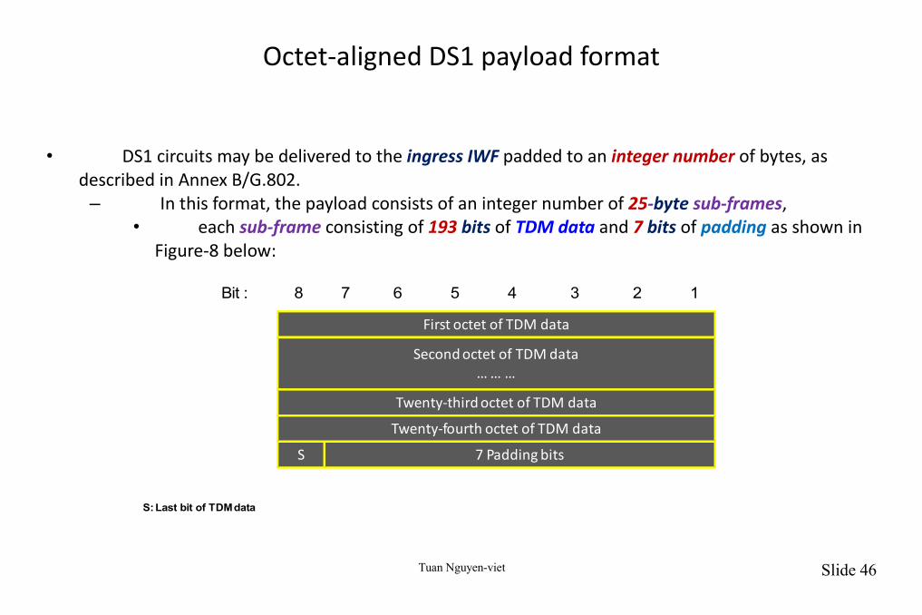
• DS1 circuits may be delivered to the ingress IWF padded to an integer number of bytes, as described in Annex B/G.802.
– In this format, the payload consists of an integer number of 25-byte sub-frames,• each sub-frame consisting of 193 bits of TDM data and 7 bits of padding as shown in
Figure-8 below:
First octet of TDM data
S 7 Padding bits
12345678Bit :
Second octet of TDM data… … …
Twenty-third octet of TDM data
Twenty-fourth octet of TDM data
S: Last bit of TDM data