sascha stegen school of electrical engineering, griffith ... mach...electrical machines and drives...
TRANSCRIPT

Sascha Stegen
School of Electrical Engineering,
Griffith University, Australia

Electrical Machines and Drives
� Motors
� Generators
� Power Electronics and Drives

Michael Faraday explored the electromagnetic induction
in 1831

http://www.evworks.com.au/tech/?section=motors
Efficiencies up to 90% and only needing
servicing every 100,000kms

� When a current flows through a conductor coil in a magnetic field, the induced magnetic force produces torque. This force is perpendicular to the wire and the magnetic field, with:
F= I L B
� Speed dependent on voltage
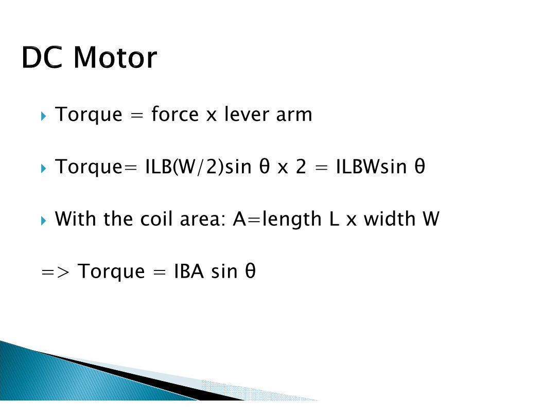
� Torque = force x lever arm
� Torque= ILB(W/2)sin θ x 2 = ILBWsin θ
� With the coil area: A=length L x width W
=> Torque = IBA sin θ

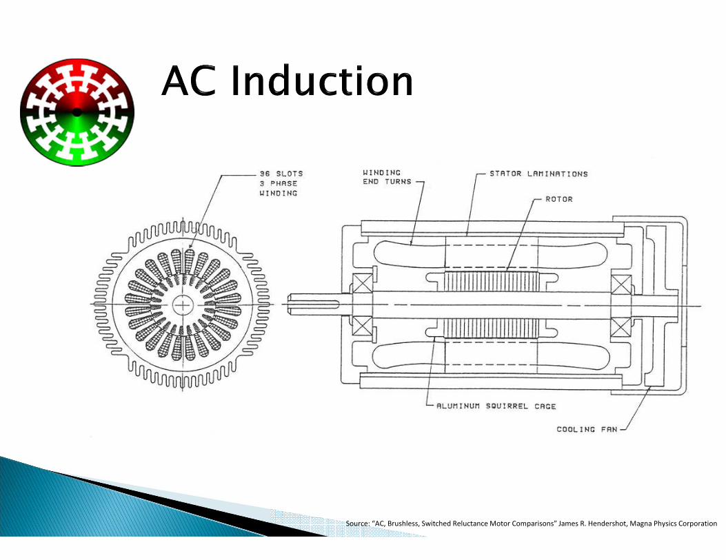
Source: “AC, Brushless, Switched Reluctance Motor Comparisons” James R. Hendershot, Magna Physics Corporation
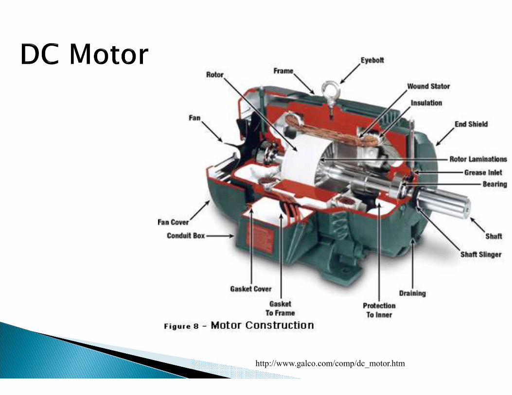
http://www.galco.com/comp/dc_motor.htm

� Much of the impetus for the development of brushless DC motors came from the computer peripheral and aerospace industries, where high performance coupled with reliability and low maintenance are essential.
� In principle, there is no difference between a brushless DC motor and the self-synchronous permanent magnet motor.
� The brushless DC motor is essentially an inside out electronically commutated DC motor, and can therefore be controlled in the same way as a conventional DC motor.

� In the synchronous motor, the stator windings are exactly the same as in the induction motor, so when connected to the 3-phase supply, a rotating magnetic weld is produced.
� But instead of having a cylindrical rotor with a cage winding, the synchronous motor has a rotor with either a DC excited winding (supplied via sliprings), or permanent magnets, designed to cause the rotor to ‘lock-on’ or ‘synchronise with’ the rotating magnetic field produced by the stator.
� Once the rotor is synchronised, it will run at exactly the same speed as the rotating field despite load variation, so under constant-frequency operation the speed will remain constant as long as the supply frequency is stable.

http://commons.wikimedia.org/w/index.php?title=User:CPI_BalNpp&
action=edit&redlink=1

� The initial success of the inverter-fed induction motor drive was due to the fact that a standard induction motor was much cheaper than a comparable DC motor,
� And this saving compensated for the relatively high cost of the inverter compared with the thyristor AC converter.
� Inverter-fed induction motor with inverter mounted directly onto motor.

� Rotors for Synchronous Machines (three phase).

� Permanent magnets are used on the rotor instead of a wound weld, typically in 2-pole and 4-pole surface-mounted versions.

� Permanent Magnetics in Electric Machines

Source: “AC, Brushless, Switched Reluctance Motor Comparisons” James R. Hendershot, Magna Physics Corporation

� High locked rotor current
� Low starting moment

�� ��
�∙ 60
��
� The number of pole pairs can be calculated as follows:
� One pole pair is necessary for one 360º step (positive and negative half of the sine wave), so the number of poles are:
N��
∙ 60
�
���∙2

��� � �����
� If parasitic effects =0 (current temperature rise, friction losses….), then:
����� � � ∙M

Pull-up torque
http://www.westernintech.com/kb/Single-
Phase_Electric_Motor_Performance_Characteristics

Motor Rating:
Continuous-duty electric motors are rated by Power, RPM, and service factor. Maximum motor
power is limited by the highest temperature at which components in the motor can continue to
function.
Any electrical energy which does not do mechanical work gets converted into heat in the motor
The service factor defines the load at which the motor is stabilised at its maximum operating
temperature. When the (load) = (rated power x service factor), the net heat gain/loss is zero.
Starting:
At start-up, the motor will apply its highest torque, locked-rotor torque (also called breakaway
torque, or starting torque). The motor can draw 600% of its nominal current at this point, and
will quickly overheat if operated for more than a few seconds if the load does not turn.
As the rotor begins to turn, torque output decreases. Torque will decrease to the pull-up torque
limit. This is the lowest torque the motor will apply while below near-synchronous speed, and
is critical in determining if a motor will operate satisfactorily.

Normal Operation
When a motor is operating at its rated horsepower and RPM, it is
applying full-load torque, and the current is full-load amps. It is the
nature of electric motors that, as long as the applied load is less than
full-load torque, the motor will operate a near-synchronous speed
draw less than full-load amps.
When operating at near synchronous speeds, motors exhibit very
good performance because, up to the breakdown torque, they will
respond to changing loads by drawing more or less current as
required to maintain a near constant operating speed. However, if the
applied load exceeds breakdown torque, the motor speed will fall off
dramatically and, if the load is not immediately reduced, the motor
will stall.


Vpe = phase-element voltage
Ipe = phase-element current
Star connection: Delta connection:
��� � 3 ∙ �� ∙ ��∙ ��� ��� � 3 ∙ �� ∙ ��
� � � �� � �
�
3
� � 3 ∙ �� ∙ ��∙ ���
� � 3 ∙ � � ∙ � �� � ∙ ���
Apparent power:
Reactive power:

http://www.rchobby-net.de/optimum/optimum.htm
http://www.becks24.de/cgi-bin/hdub/YaBB.pl?num=1234390242

If the star connection reaches a torque of 75% to 80% at full load
speed, then the motor can be connected in Delta mode.
In Delta configuration the phase voltage increases by 173%, as also the
phase does. The line current increases three times its value in star
connection, as does the electric power.
During the transition period from star to delta, the motor must be free
running with little deceleration. Due to the electromagnetic field inside
the turning rotor, the motor generates a voltage of its own, which
randomly add to or subtract from the applied line voltage. This is called
transient current. These changeover transients appear normally just for
a few milliseconds and cause voltage surges and spikes.

1 Direct start
2 Star-Delta-Start
3 Softstart

1 Direct start
2 Star-Delta-Start
3 Softstart

How to regulate speed and/or torque
mechanically?

Universal motor
� DC or AC voltage
� Up to 1kW
� Laminated pole-pieces
http://www.daviddarling.info/encyclopedia/D/AE_drill.html


Source: “AC, Brushless, Switched Reluctance Motor Comparisons” James R. Hendershot, Magna Physics Corporation

� POWER RANGE FOR MOTORS AND DRIVESPOWER RANGE FOR MOTORS AND DRIVESPOWER RANGE FOR MOTORS AND DRIVESPOWER RANGE FOR MOTORS AND DRIVES◦ Continuous power rating for various types of motor

◦ Power range for various types of drive

� Financially (lifetime of electrical motor)◦ Approximately 97% electrical energy costs
◦ 3% material costs including maintenance
� Energy (lifetime of electrical motor)◦ Between 90 and 99.5% (Pel->Pmech)

� OLD:
In 1998 the European commission CEMEP defined three efficiency classes
◦ EFF3 = Motor with low efficiency
◦ EFF2 = Motor with medium efficiency
◦ EFF1 = Motor with highest efficiency

� In 2009 a worldwide norm for energy classes for asynchron machines 0.75 kW to 375 kW was developed (EN 60034-30:2009).
◦ IE1 = Standard efficiency grade (compareable EFF2 >90%, since June 2011 just limited allowed)
◦ IE2 = High efficiency grade (compareable EFF1 >94%)
◦ IE3 = Premium efficiency grade
◦ IE4 = Super Premium efficiency grade (> 97%)

� Basically every motor with permanent magnets can be used as a generator.
◦ DC motors◦ AC motors with permanent magnets
� Or: applying an electro magnetic field on the rotor and inducing AC voltage into the cage windings.

www.physik3d.de, by Arthur Kronenberger 2007

Motor comparisonMotor comparisonMotor comparisonMotor comparison
http://xorl.wordpress.com/2011/03/05/the-basics-of-4-stroke-internal-combustion-engines/

Motor comparisonMotor comparisonMotor comparisonMotor comparison
http://xorl.wordpress.com/2011/03/05/the-basics-of-4-stroke-internal-
combustion-engines/

Motor comparisonMotor comparisonMotor comparisonMotor comparison

http://www.afdc.energy.gov/afdc/vehicles/propane_what_is.html

Motor comparisonsMotor comparisonsMotor comparisonsMotor comparisons
� Petrol - 15% - 20%◦ Also depending on Fuel:
� Petrol (91-99 RON (research octane rating)
� LPG (Liquefied Petroleum Gas) – Low energy rating (102-108 RON)
� Diesel – up to 30%
� Hybrid - 15% - 97%
� Electric – up to or even over 97%◦ As energy supply/storage:
� Batteries
� Solar cells
� Hydrogen cells
� Ultra capacitor


http://www.bennettclayton.com.au/?page_id=64

� P. Schavemaker and L. V. D. Sluis, “Electrical Power System Essentials”, Wiley, 2009
� J. L. Kirtley, “Electric Power Principles”, Wiley, 2010,
� T. Wildi, Electrical Machines, Drives, and Power Systems, Fourth Edition, Prentice Hall, 2000
� Austin Hughes, “Electric Motors and Drives -Fundamentals, Types and Applications,” Elsevier
� www.wikipedia.de� http://www.patchn.com� C. C. Chan, “The state of the art of electric, hybrid
vehicles, and Fuel Cell Vehicles,” Proc. IEEE, 2010� http://www.moeller.net