sar test report for atid co., ltd. 3g smart phone model … · ed in whol laborator liance testi...
TRANSCRIPT
SHENZHEN LCS COMPLIANCE TESTING LABORATORY LTD.Report FCC ID: VUJ-AT312 No.: LCS1603171371E
This report shall not be reproduced except in full, without the written approval of Shenzhen LCS Compliance Testing Laboratory Ltd.
Page 1 of 110
SAR TEST REPORT
For
ATID CO., LTD.
3G Smart phone
Model No.: AT312
Additional Model No.: P60-B
Prepared for : ATID CO., LTD. Address : #1210, Byuksan/GyungIn Digital vally II, 184, Gasan
Digital-2ro, Guemchon-gu, Seoul, Korea
Prepared by : Shenzhen LCS Compliance Testing Laboratory Ltd. Address : 1/F., Xingyuan Industrial Park, Tongda Road, Bao’an
Avenue, Bao’an District, Shenzhen, Guangdong, China Tel : (86)755-82591330 Fax : (86)755-82591332 Web : www.LCS-cert.com Mail : [email protected]
Date of receipt of test sample : March 17, 2016 Number of tested samples : 1 Serial number : Prototype Date of Test : March 17, 2016~July 19, 2016 Date of Report : July 20, 2016

SHEN
T
R
D
TA
T
A
A
TS
T
T
MSTSthasitT
T
M
O
M
R
R
NZHEN LCS CO
This report shal
Report Refe
Date Of Issu
Testing LabAddress .......
Testing Loca
Applicant’s
Address .......
Test Specifitandard .....
Test Report F
TRF Origina
Master TRF henzhen L
This publicahenzhen LC
he material.ssume liabits placemen
Test Item D
Trade Mark .
Model/Type
Operation Fr
Modulation T
Ratings .......
Result ........
Co
Linda He/
OMPLIANCE T
ll not be reprod
erence No. .
ue ................
boratory Na..................
ation/ Proce
Name .......
..................
cation: ..................
Form No. ..
ator .............
..................LCS Compliation may bCS Complia Shenzhen Llity for dam
nt and contexDescription.
..................
Reference .
requency ....
Type ..........
..................
...................
ompiled by
/ File admin
TESTING LABO
duced except in
................ :
............... :
ame ........ : ............... :
edure ....... :
................ :
............... :
............... :
............... :
............... :
............... : iance Testi
be reproducance TestingLCS Comp
mages resultxt. . ............... :
............... :
............... :
............... :
............... :
............... :
................ :
y:
nistrators
ORATORY LTD
n full, without t
SAR TLCS1603
July 20, 2
Shenzhen1/F., XingBao’an D
Full appliPartial appOther stan
ATID CO#1210, ByGuemcho IEEE 15247CFR §2LCSEMC
Shenzhen
Dated 201ing Laboraed in wholg Laboratorliance Testiting from th
3G Smar
AT312 GSM 850BluetoothGSM(GMSSS,OFDDC 3.7V bRecharge Positive
Glin L
D.Report
the written app
Page 2 of 110
TEST RE3171371E
2016
n LCS Comgyuan Indusistrict, Shen
ication of Hplication ofndard testin
O., LTD. yuksan/Gyu
on-gu, Seoul
28:2013/KD2.1093
C-1.0
n LCS Comp
14-09 atory Ltd. Ae or in partry Ltd. is acing Laborat
he reader's i
rt phone
0/PCS1900,h4.0 MSK,8PSK)DM), Blueto
by LithiumVoltage: D
Supervise
Lu/ Techniq
FCC ID:
proval of Shenzh
EPORT
mpliance Testrial Park, Tnzhen, Guan
Harmonised f Harmoniseng method
ungIn Digital, Korea
DB865664
pliance Test
All rights ret for non-cocknowledgetory Ltd. taknterpretatio
WCDMA B
, WCDMA/oth(GFSK,8
m ion polymeDC 5.0V/100
ed by:
que principa
VUJ-AT312
hen LCS Comp
esting LaboTongda Roangdong, Ch
standards ed standards
al vally II, 1
ting Labora
eserved. ommercial
ed as copyrikes norespoon of the rep
Band II/ V,
/HSDPA/H8DPSK, π/4er battery(200mA
al G
No.
pliance Testing
oratory Ltdad, Bao’an
hina
s
184, Gasan
atory Ltd.
purposes aight owner aonsibility forproduced m
WLAN2.4G
HSUPA(QPS4-DQPSK )2000mAh)
Approv
Gavin Liang
: LCS16031713
g Laboratory Lt
d. Avenue,
Digital-2ro
as long as thand source r and will n
material due
G,
SK), WIFI(D
ed by:
g/ Manager
371E
td.
,
he of
not to
D

SHENZHEN LCS COMPLIANCE TESTING LABORATORY LTD.Report FCC ID: VUJ-AT312 No.: LCS1603171371E
This report shall not be reproduced except in full, without the written approval of Shenzhen LCS Compliance Testing Laboratory Ltd.
Page 3 of 110
SAR -- TEST REPORT
Test Result Positive The test report merely corresponds to the test sample. It is not permitted to copy extracts of these test result without the written permission of the test laboratory.
Test Report No. : LCS1603171371E July 20, 2016 Date of issue
Type / Model......................... : AT312 EUT....................................... : 3G Smart phone Applicant.............................. : ATID CO., LTD. Address.................................. : #1210, Byuksan/GyungIn Digital vally II, 184, Gasan
Digital-2ro, Guemchon-gu, Seoul, Korea Telephone.............................. : / Fax......................................... : / Manufacturer....................... : Shenzhen BoRui Technology Co., Ltd Address.................................. : Room 1502, Unit B3,Kexing Science Park, No.5 Keyuan
Road, Middle district of Hi-tech Park, Nanshan District, Shenzhen, China.
Telephone.............................. : / Fax......................................... : / Factory.................................. : Shenzhen BoRui Technology Co., Ltd Address.................................. : Room 1502, Unit B3,Kexing Science Park, No.5 Keyuan
Road, Middle district of Hi-tech Park, Nanshan District, Shenzhen, China.
Telephone.............................. : / Fax......................................... : /

SHENZHEN LCS COMPLIANCE TESTING LABORATORY LTD.Report FCC ID: VUJ-AT312 No.: LCS1603171371E
This report shall not be reproduced except in full, without the written approval of Shenzhen LCS Compliance Testing Laboratory Ltd.
Page 4 of 110
Revison History
Revision Issue Date Revisions Revised By
00 2016-07-02 Initial Issue Gavin Liang 01 2016-07-20 Re measure according to TCB questions Gavin Liang

SHENZHEN LCS COMPLIANCE TESTING LABORATORY LTD.Report FCC ID: VUJ-AT312 No.: LCS1603171371E
This report shall not be reproduced except in full, without the written approval of Shenzhen LCS Compliance Testing Laboratory Ltd.
Page 5 of 110
TABLE OF CONTENTS
1. TEST STANDARDS AND TEST DESCRIPTION ..................................................................................................................... 6
1.1. TEST STANDARDS ................................................................................................................................................................... 6 1.2. TEST DESCRIPTION................................................................................................................................................................. 6 1.3. GENERAL REMARKS ............................................................................................................................................................... 6 1.4. PRODUCT DESCRIPTION .......................................................................................................................................................... 6 1.5. STATEMENT OF COMPLIANCE ................................................................................................................................................. 8
2. TEST ENVIRONMENT ............................................................................................................................................................... 9
2.1. TEST FACILITY ........................................................................................................................................................................ 9 2.2. ENVIRONMENTAL CONDITIONS ............................................................................................................................................... 9 2.3. SAR LIMITS ............................................................................................................................................................................ 9 2.4. EQUIPMENTS USED DURING THE TEST .................................................................................................................................. 10
3. SAR MEASUREMENTS SYSTEM CONFIGURATION ....................................................................................................... 12
3.1. SARMEASUREMENT SET-UP................................................................................................................................................. 12 3.2. OPENSAR E-FIELD PROBE SYSTEM ..................................................................................................................................... 13 3.3. PHANTOMS ........................................................................................................................................................................... 14 3.4. DEVICE HOLDER ................................................................................................................................................................... 14 3.5. SCANNING PROCEDURE ........................................................................................................................................................ 15 3.6. DATA STORAGE AND EVALUATION ....................................................................................................................................... 16 3.7. POSITION OF THE WIRELESS DEVICE IN RELATION TO THE PHANTOM ..................................................................................... 17 3.8. TISSUE DIELECTRIC PARAMETERS FOR HEAD AND BODY PHANTOMS .................................................................................. 19 3.9. TISSUE EQUIVALENT LIQUID PROPERTIES ............................................................................................................................. 19 3.10. SYSTEM CHECK .................................................................................................................................................................... 20 3.11. SAR MEASUREMENT PROCEDURE ......................................................................................................................................... 22 3.12. POWER REDUCTION .............................................................................................................................................................. 27 3.13. POWER DRIFT ....................................................................................................................................................................... 27
4. TEST CONDITIONS AND RESULTS ...................................................................................................................................... 28
4.1. CONDUCTED POWER RESULTS .............................................................................................................................................. 28 4.2. MANUFACTURING TOLERANCE ............................................................................................................................................. 31 4.3. TRANSMIT ANTENNAS AND SAR MEASUREMENT POSITION ................................................................................................. 35 4.4. SAR MEASUREMENT RESULTS ............................................................................................................................................. 36 4.5. SIMULTANEOUS TX SAR CONSIDERATIONS ......................................................................................................................... 39 4.6. SAR MEASUREMENT VARIABILITY ...................................................................................................................................... 41 4.7. GENERAL DESCRIPTION OF TEST PROCEDURES ...................................................................................................................... 41 4.8. MEASUREMENT UNCERTAINTY (300MHZ-6GHZ) ................................................................................................................ 42 4.9. SYSTEM CHECK RESULTS ..................................................................................................................................................... 43 4.10. SAR TEST GRAPH RESULTS .................................................................................................................................................. 51
5. CALIBRATION CERTIFICATES ............................................................................................................................................ 61
5.1 PROBE-EP221 CALIBRATION CERTIFICATE .......................................................................................................................... 61 5.2 SID835DIPOLE CALIBRATION CERITICATE .......................................................................................................................... 70 5.3 SID1900 DIPOLE CALIBRATION CERITICATE ........................................................................................................................ 81 5.4 SID2450 DIPOLE CALIBRATION CERITICATE ........................................................................................................................ 92
6. EUT TEST PHOTOGRAPHS .................................................................................................................................................. 103
7. EUT PHOTOGRAPHS ............................................................................................................................................................. 110
SHENZHEN LCS COMPLIANCE TESTING LABORATORY LTD.Report FCC ID: VUJ-AT312 No.: LCS1603171371E
This report shall not be reproduced except in full, without the written approval of Shenzhen LCS Compliance Testing Laboratory Ltd.
Page 6 of 110
1. TEST STANDARDS AND TEST DESCRIPTION 1.1. Test Standards IEEE Std C95.1, 2005: IEEE Standard for Safety Levels with Respect to Human Exposure to Radio Frequency Electromagnetic Fields, 3 KHz to 300 GHz. It specifies the maximum exposure limit of 1.6 W/kg as averaged over any 1 gram of tissue for portable devices being used within 20 cm of the user in the uncontrolled environment. IEEE Std 1528™-2013: IEEE Recommended Practice for Determining the Peak Spatial-Average Specific Absorption Rate (SAR) in the Human Head from Wireless Communications Devices: Measurement Techniques. FCC Part 2.1093 Radiofrequency Radiation Exposure Evaluation:Portable Devices KDB447498 D01 General RF Exposure Guidance v06 : Mobile and Portable Device RF Exposure Procedures and Equipment Authorization Policies KDB648474 D04, Handset SAR v01r03: SAR Evaluation Considerations for Wireless Handsets KDB865664 D01 SAR Measurement 100 MHz to 6 GHz v01r04 : SAR Measurement Requirements for 100 MHz to 6 GHz KDB865664 D02 RF Exposure Reporting v01r02: RF Exposure Compliance Reporting and Documentation Considerations KDB248227 D01 802.11 Wi-Fi SAR v02r02: SAR GUIDANCE FOR IEEE 802.11 (Wi-Fi) TRANSMITTERS KDB941225 D01 3G SAR Procedures v03r01: 3G SAR MEAUREMENT PROCEDURES KDB 941225 D06 Hotspot Mode v02r01: SAR EVALUATION PROCEDURES FOR PORTABLE DEVICES WITH WIRELESS ROUTER CAPABILITIES
1.2. Test Description The EUT battery must be fully charged and checked periodically during the test to ascertain uniform power . And Test device is identical prototype.
1.3. General Remarks Date of receipt of test sample : March 17, 2016 Testing commenced on : April 18, 2016 Testing concluded on : July 19, 2016
1.4. Product Description The ATID CO., LTD.Model: AT312 or the “EUT” as ref erred to in this report; more general information as follows, for more details, refer to the user’s manual of the EUT. General Description Product Name: 3G Smart phone
Trade Mark:
Model/Type reference: AT312 Listed Model(s): AT312, P60-B
Modulation Type: DC 3.7V by Lithium ion polymer battery(2000mAh) Recharge Voltage: DC 5.0V/1000mA
Device category: Common mobile Device Exposure category: General population/uncontrolled environment EUT Type: Production Unit Hardware Version T09B-00-1107 Software Version: V 2.2
Power supply: DC 3.7V by Lithium ion polymer battery(2000mAh) Recharge Voltage: DC 5.0V/1000mA
Hotspot: Supported, power not reduced when Hotspot open The EUT is GSM,WCDMA, mobile phone. the mobile phone is intended for speech and Multimedia Message Service (MMS) transmission. It is equipped with GPRS/EDGE class 12 for GSM850, PCS1900, WCDMA Band II,Band V, and Bluetooth, WiFi2.4G and camera functions. For more information see the following datasheet

SHENZHEN LCS COMPLIANCE TESTING LABORATORY LTD.Report FCC ID: VUJ-AT312 No.: LCS1603171371E
This report shall not be reproduced except in full, without the written approval of Shenzhen LCS Compliance Testing Laboratory Ltd.
Page 7 of 110
Technical Characteristics GSM Support Networks GSM, GPRS, EGPRS Support Band GSM850, PCS1900 Frequency GSM850: 824.2~848.8MHz
GSM1900: 1850.2~1909.8MHz Power Class: GSM850:Power Class 5
PCS1900:Power Class 0 Modulation Type: GMSK for GSM/GPRS, 8-PSK for EGPRS GSM Release Version R99 GPRS Multislot Class 12 EGPRS Multislot Class 12 DTM Mode Not Supported Antenna Type PIFA Antenna, 1.2dBi(Max.) UMTS Support Networks WCDMA RMC12.2K,HSDPA,HSUPA Operation Band: WCDMA Band II, Band V Frequency Range WCDMA Band II: 1852.4 ~ 1907.6MHz
WCDMA Band V: 826.4 ~ 846.6MHz Modulation Type: QPSK for WCDMA/HSUPA/HSDPA Power Class: Class 3 WCDMA Release Version: R99 HSDPA Release Version: R10 HSUPA Release Version: R6 DC-HSUPA Release Version: Not Supported Antenna Type PIFA Antenna, 1.2dBi(Max.)
WIFI 2.4G Supported Standards: 802.11b/802.11g/802.11n(HT20&HT40) Operation frequency: 2412-2462MHz for 11b/g/n(HT20)
2422-2452MHz for 11n(HT40) Type of Modulation: CCK, OFDM, QPSK, BPSK, 16QAM, 64QAM Data Rate: 1-11Mbps, 6-54Mbps, up to 150Mbps Channel number: 802.11b/802.11g/802.11n(HT20): 11; 802.11n(HT40): 7 Channel separation: 5MHz Antenna Description PIFA Antenna, 1.0dBi(Max.) Bluetooth Bluetooth Version: V4.0 Modulation: GFSK(1Mbps), π/4-DQPSK(2Mbps), 8DPSK(3Mbps) Operation frequency: 2402MHz~2480MHz Channel number: 40/79 Channel separation: 1MHz/2MHz Antenna Description PIFA Antenna, 1.0dBi(Max.)

SHENZHEN LCS COMPLIANCE TESTING LABORATORY LTD.Report FCC ID: VUJ-AT312 No.: LCS1603171371E
This report shall not be reproduced except in full, without the written approval of Shenzhen LCS Compliance Testing Laboratory Ltd.
Page 8 of 110
1.5. Statement of Compliance The maximum of results of SAR found during testing for AT312 are follows:
<Highest Reported standalone SAR Summary> Classment
Class Frequency
Band Head
(Report SAR1-g (W/Kg) Hotspot
(Report SAR1-g (W/Kg) Body-worn
(Report SAR1-g (W/Kg)
PCE
GSM 850 0.527 0.904 0.904 GSM1900 0.113 0.252 0.252
WCDMA Band V 0.211 0.381 0.381 WCDMA Band II 0.094 0.211 0.211
DTS WIFI2.4G 0.552 0.269 0.269
This device is in compliance with Specific Absorption Rate (SAR) for general population/uncontrolled exposure limits (1.6 W/kg) specified in FCC 47 CFR part 2 (2.1093) and ANSI/IEEE C95.1-2005, and had been tested in accordance with the measurement methods and procedures specified in IEEE 1528-2013.
<Highest Reported simultaneous SAR Summary>
Exposure Position Frequency Band
Reported SAR1-g (W/kg)
Classment Class
Highest Reported Simultaneous Transmission SAR1-g (W/kg)
Hotspot GSM 850 0.904 PCE 1.173 WIFI2.4G 0.269 DTS
SHENZHEN LCS COMPLIANCE TESTING LABORATORY LTD.Report FCC ID: VUJ-AT312 No.: LCS1603171371E
This report shall not be reproduced except in full, without the written approval of Shenzhen LCS Compliance Testing Laboratory Ltd.
Page 9 of 110
2. TEST ENVIRONMENT 2.1. Test Facility The test facility is recognized, certified, or accredited by the following organizations:
Site Description EMC Lab. : CNAS Registration Number. is L4595.
FCC Registration Number. is 899208. Industry Canada Registration Number. is 9642A-1. VCCI Registration Number. is C-4260 and R-3804. ESMD Registration Number. is ARCB0108. UL Registration Number. is 100571-492. TUV SUD Registration Number. is SCN1081. TUV RH Registration Number. is UA 50296516-001.
2.2. Environmental conditions During the measurement the environmental conditions were within the listed ranges:
Temperature: 18-25 ° C Humidity: 40-65 % Atmospheric pressure: 950-1050mbar
2.3. SAR Limits FCC Limit (1g Tissue)
EXPOSURE LIMITS
SAR (W/kg) (General Population /
Uncontrolled Exposure Environment)
(Occupational / Controlled Exposure
Environment) Spatial Average(averaged over the whole body) 0.08 0.4
Spatial Peak(averaged over any 1 g of tissue) 1.6 8.0
Spatial Peak(hands/wrists/ feet/anklesaveraged over 10 g) 4.0 20.0
Population/Uncontrolled Environments are defined as locations where there is the exposure of individual who have no knowledge or control of their exposure. Occupational/Controlled Environments are defined as locations where there is exposure that may be incurred by people who are aware of the potential for exposure (i.e. as a result of employment or occupation).

SHENZHEN LCS COMPLIANCE TESTING LABORATORY LTD.Report FCC ID: VUJ-AT312 No.: LCS1603171371E
This report shall not be reproduced except in full, without the written approval of Shenzhen LCS Compliance Testing Laboratory Ltd.
Page 10 of 110
2.4. Equipments Used during the Test
Test Equipment Manufacturer Type/Model Serial NumberCalibration
Calibration Date
Calibration Due
PC Lenovo G5005 MY42081102 N/A N/A
Signal Generator Angilent E4438C MY42081396 09/25/2015 09/24/2016
Multimeter Keithley MiltiMeter 2000 4059164 10/01/2015 09/30/2016
S-parameter Network Analyzer Agilent 8753ES US38432944 09/25/2015 09/24/2016
Wireless Communication
Test Set R & S CMU200 105988 09/25/2015 09/24/2016
Power Meter R & S NRVS 100469 09/25/2015 09/24/2016
Power Sensor R & S NRV-Z51 100458 09/25/2015 09/24/2016
Power Sensor R & S NRV-Z32 10057 09/25/2015 09/24/2016
E-Field PROBE SATIMO SSE5 SN 17/14 EP221 09/01/2015 08/31/2016
DIPOLE 835 SATIMO SID 835 SN 07/14 DIP 0G835-303 10/01/2015 09/30/2018
DIPOLE 1900 SATIMO SID 1900 SN 30/14 DIP 1G900-333 09/01/2015 08/31/2018
DIPOLE 2450 SATIMO SID 2450 SN 07/14 DIP 2G450-306 10/01/2015 09/30/2018
COMOSAR OPEN Coaxial Probe SATIMO OCPG 68 SN 40/14
OCPG68 10/01/2015 09/30/2016
Communication Antenna SATIMO ANTA57 SN 39/14
ANTA57 10/01/2015 09/30/2016
Mobile Phone POSITIONING
DEVICE SATIMO MSH98 SN 40/14
MSH98 N/A N/A
DUMMY PROBE SATIMO DP60 SN 03/14 DP60 N/A N/A
SAM PHANTOM SATIMO SAM117 SN 40/14 SAM117 N/A N/A
6 AXIS ROBOT KUKA KR6-R900 501217 N/A N/A
High Power Solid State Amplifier
(80MHz~1000MHz)
Instruments for Industry CMC150 M631-0627 09/25/2015 09/24/2016
Medium Power Solid State Amplifier (0.8~4.2GHz)
Instruments for Industry S41-25 M629-0539 09/25/2015 09/24/2016
Wave Tube Amplifier 48 GHz at 20Watt
Hughes Aircraft Company 1277H02F000 102 09/25/2015 09/24/2016
Note:
1) Per KDB865664D01 requirements for dipole calibration, the test laboratory has adopted three year extended calibration interval. Each measured dipole is expected to evalute with following criteria at least on annual interval.
a) There is no physical damage on the dipole; b) System check with specific dipole is within 10% of calibrated values; c) The most recent return-loss results,measued at least annually,deviates by no more than 20% from the
previous measurement; d) The most recent measurement of the real or imaginary parts of the impedance, measured at least annually is
within 5Ω from the provious measurement.

SHENZHEN LCS COMPLIANCE TESTING LABORATORY LTD.Report FCC ID: VUJ-AT312 No.: LCS1603171371E
This report shall not be reproduced except in full, without the written approval of Shenzhen LCS Compliance Testing Laboratory Ltd.
Page 11 of 110
2) Network analyzer probe calibration against air, distilled water and a shorting block performed before measuring liquid parameters.

SHENZHEN LCS COMPLIANCE TESTING LABORATORY LTD.Report FCC ID: VUJ-AT312 No.: LCS1603171371E
This report shall not be reproduced except in full, without the written approval of Shenzhen LCS Compliance Testing Laboratory Ltd.
Page 12 of 110
3. SAR MEASUREMENTS SYSTEM CONFIGURATION 3.1. SARMeasurement Set-up
The OPENSAR system for performing compliance tests consist of the following items: A standard high precision 6-axis robot (KUKA) with controller and software. KUKA Control Panel (KCP) A dosimetric probe, i.e., an isotropic E-field probe optimized and calibrated for usage in tissue simulating liquid. The probe is equipped with a Video Positioning System(VPS). The stress sensor is composed with mechanical and electronic when the electronic part detects a change on the electro-mechanical switch,It sends an “Emergency signal” to the robot controller that to stop robot’s moves A computer operating Windows XP. OPENSAR software Remote control with teaches pendant and additional circuitry for robot safety such as warning lamps, etc. The SAM phantom enabling testing left-hand right-hand and body usage. The Position device for handheld EUT Tissue simulating liquid mixed according to the given recipes . System validation dipoles to validate the proper functioning of the system.

SHEN
T
NZHEN LCS CO
This report shal
3.2. OPEThe SAR mein the classi Probe Spec Construction
CalibrationIS
Frequen
Directiv
Dynami
Dimens
Applicat
Isotropic E-F The isotropicontrolled ecalibration w The E-Field
OMPLIANCE T
ll not be reprod
ENSAR E-feasurementscal triangula
cification
nSymmetrica
SO/IEC 1702
ncy
vity
ic Range
sions
tion
Field Probe
c E-Field pronvironment.
will change.
probe utilize
TESTING LABO
duced except in
field Probes were condur configuratio
al design withInterleavedBuilt-in shiePEEK enclo
25 calibration
700 MLinea
0.25 0.5 d
0.01WLinea
OverTip dDista
GeneDosimCom
obe has beenDepending o
es a triangula
ORATORY LTD
n full, without t
e Systemucted with thon and optim
h triangular csensors
elding againsosure materi
n service ava
MHz to 3 GHarity:0.25dB(
dB in HSL (rB in tissue m
W/kg to > 10arity: 0.25 dB
rall length: 33iameter: 5 m
ance from pro
eral dosimetrmetry in stropliance tests
n fully calibraon the freque
ar sensor arr
D.Report
the written appPage 13 of 110
he dosimetricmized for dos
core
st static chargal (resistant
ailable.
Hz; (700 MHz to
rotation aroumaterial (rota
00 W/kg; B
30 mm (Tip: mm (Body: 8obe tip to sen
ry up to 3 GHng gradient f
s of Mobile P
ated and assency for whic
rangement a
FCC ID:
proval of Shenzh0
c probe EP22simetric evalu
ges to organic so
3GHz)
nd probe axation normal t
16mm) mm) nsor centers
Hz fields
Phones
sessed for isoch the probe
s detailed in
VUJ-AT312
hen LCS Comp
20 (manufactuation.
olvents, e.g.,
is) to probe axis
: 2.5 mm
otropicity, anis calibrated
the diagram
No.
pliance Testing
tured by SAT
, DGBE)
s)
nd boundary d the method
m below:
: LCS16031713
g Laboratory Lt
TIMO), desig
effect within d utilized for
371E
td.
gned
a

SHENZHEN LCS COMPLIANCE TESTING LABORATORY LTD.Report FCC ID: VUJ-AT312 No.: LCS1603171371E
This report shall not be reproduced except in full, without the written approval of Shenzhen LCS Compliance Testing Laboratory Ltd.
Page 14 of 110
3.3. Phantoms The SAM Phantom SAM117 is constructed of a fiberglass shell ntegrated in a wooden table. The shape of the shell is in compliance with the specification set in IEEE P1528 and CENELEC EN62209-1 , EN62209-2:2010.The phantom enables the dosimetric evaluation of left and right hand phone usage as well as body mounted usage at the flat phantom region. A cover prevents the evaporation of the liquid. Reference markings on the Phantom allow the complete setup of allpredefined phantom positions and measurement grids by manually teaching three points in the robo System checking was performed using the flat section, whilst Head SAR tests used the left and right head profile sections. Body SAR testing also used the flat section between the head profiles.
SAM Twin Phantom
3.4. Device Holder In combination with the Generic Twin PhantomSAM117, the Mounting Device enables the rotation of the mounted transmitter in spherical coordinates whereby the rotation points is the ear opening. The devices can be easily, accurately, and repeatedly positioned according to the FCC and CENELEC specifications. The device holder can be locked at different phantom locations (left head, right head, flat phantom).
Device holder supplied by SATIMO

SHENZHEN LCS COMPLIANCE TESTING LABORATORY LTD.Report FCC ID: VUJ-AT312 No.: LCS1603171371E
This report shall not be reproduced except in full, without the written approval of Shenzhen LCS Compliance Testing Laboratory Ltd.
Page 15 of 110
3.5. Scanning Procedure
The procedure for assessing the peak spatial-average SAR value consists of the following steps
Power Reference Measurement The reference and drift jobs are useful jobs for monitoring the power drift of the device under test in the batch process. Both jobs measure the field at a specified reference position, at a selectable distance from the phantom surface. The reference position can be either the selected section's grid reference point or a user point in this section. The reference job projects the selected point onto the phantom surface, orients the probe perpendicularly to the surface, and approaches the surface using the selected detection method. Area Scan The Area Scan is used as a fast scan in two dimensions to find the area of high field values before running a detailed measurement around the hot spot.Before starting the area scan a grid spacing of 15 mm x 15 mm is set. During the scan the distance of the probe to the phantom remains unchanged. After finishing area scan, the field maxima within a range of 2 dB will be ascertained.
Zoom Scan Zoom Scans are used to estimate the peak spatial SAR values within a cubic averaging volume containing 1 g and 10 g of simulated tissue. The default Zoom Scan is done by 7x7x7 points within a cube whose base is centered around the maxima found in the preceding area scan.

SHEN
T
NZHEN LCS CO
This report shal
Power Drift The drift jobprocedure, reading conreference mprocess. Insoftware sto
3.6. DataData StoragThe OPENSreadings frocalibration dsoftware evaverification oparameter sthe device s The measurtype ([V/m], or show meaexported to Data EvaluaThe OPENSmicrovolt reamodules of t Probe param
Device para
Media param
These paramcan be impomeasuring mvisualization The first stecharacteristtransmissionsignal must
With Vi = coUi = incf = crdcpi =
From the co
With Vi Norm
Conv
OMPLIANCE T
ll not be reprod
measuremeb measures and with the
nducted withmeasuremenn the propertop the meas
a Storage ge SAR softwareom the probedata, liquid paaluates the dof the complesettings. For setup, the pa
red data can [A/m], [°C], aningless reperform the
ation SAR softwareadings at thethe software
meters: - Se- Co- Di
ameters: - Fre- Cr
meters: - Co- De
meters must orted into themode of the mn and export
p of the evalics of the den factor frombe known to
ompensatednput signal ofrest factor of diode comp
ompensated
= compemi = senso
[mV/(VvF = sensit
TESTING LABO
duced except in
ent the field at t
e same settihin the last rnt. This allowties of the Dsurements if
and Evalu
e stores the ae sensors), toarameters andesired unit aete softwareexample, if arameter can
be visualize[mW/g], [mWsults, e.g., a evaluation w
e automaticae probe conne:
ensitivity onversion facode compresequency rest factor nductivity ensity be set corre
e software fromultimeter omodes, the
luation is a litector diode.
m the diode too correctly co
signal of chf channel i exciting field
pression poin
input signals
ensated signr sensitivity oV/m)2] for E-ivity enhance
ORATORY LTD
n full, without t
the same locings. The dreference me
ws a user to Drift job, the f this limit is
uation
acquired datogether with and device freand format fosetup even
a measuremebe corrected
ed or exporteW/cm²], [dBre
SAR output with other sof
ally executes nector. The p
Nctor Cssion point f c σ ρ
ectly in the soom the configption, the paparameters s
nearization o. The compeo the evaluatompensate fo
annel i ( i = ( i = x, y, z
d t
s the primary
al of channeof channel i -field Probes ement in solu
D.Report
the written appPage 16 of 110
cation as thrift measuremeasurementmonitor the
user can spexceeded.
ta from the dall necessaryequency andor output eacafter the meent has beend afterwards
ed in differentel], etc.). Somt in a losslessftware packa
the followingparameters u
ormi, ai0, ai1ConvFi
Dcpi
cf σ
oftware. Theguration filesarameters of stored in the
of the filterednsation depe
tion electronior peak powe
= x, y, z ) )
y field data fo
el i ution
FCC ID:
proval of Shenzh0
e most recement gives tt. Several dre power drift ecify a limit
ata acquisitioy software pa modulation
ch time the dasurement an performed s and the data
t units or formme of these us media will aages.
g proceduresused in the ev
1, ai2
y can be fous issued for ththe actual sy
e correspond
d input signaends on the cs.If the excer. The formu
or each chan
(i = x, y, z)(i = x, y, z)
VUJ-AT312
hen LCS Comp
nt referencethe field diffeift measuremof the devicfor the drift
on electronicarameters fodata) in meaata is visuali
and allows cowith a wronga can be re-e
mats, dependunits are not always be ze
s to calculatevaluation are
nd in the comhe OPENSAystem setup ing documen
l to account finput signal, iting field is pula for each
nel can be e
No.
pliance Testing
e job within terence in dBments are pce under tesand have O
cs as raw daor the data evasurement filized or expoorrection of ig crest factorevaluated.
ding on the savailable in
ero. Raw dat
e the field une stored in th
mponent docAR componen
are used. Innt files are us
for the compthe diode ty
pulsed, the cchannel can
evaluated:
: LCS16031713
g Laboratory Lt
the same B from the ossible for o
st within a baOPENSAR
ta (in microvvaluation (prles . The rted. This allncorrect r parameter i
selected probcertain situata can also b
nits from the he configurat
cuments or thnts. In the dir
n the scan sed.
pression pe and the D
crest factor o be given as
371E
td.
one atch
volt robe
ows
in
be tions
be
ion
hey rect
DC-of the s:

SHEN
T
NZHEN LCS CO
This report shal
aij f Ei Hi
The RSS va
The primary
with SAR Etoσ ρ
Note that thesimulation li
3.7. PosiGeneral coThis standaposition. The power f
Where Ppwe= Etot=total el Htot=total m
OMPLIANCE T
ll not be reprod
= sensor s = carrie = elec = mag
alue of the fie
y field data ar
= local sot = tota = con = equ
e density is nquid.
ition of thensiderationrd specifies t
flow density i
=Equivalent ectric field st
magnetic field
Wt WidthWbWidthA MidpB Midpo
Picture 1-a
TESTING LABO
duced except in
ensitivity facer frequencyctric field stregnetic field st
eld compone
re used to ca
pecific absorl field strengtnductivity in uivalent tissu
normally set
e wirelesss two handset
is calculated
power densitrength in V/md strength in
h of the handh of the bottopoint of the woint of the wi
a Typical “fix
ORATORY LTD
n full, without t
ctors for H-fiey [GHz] ength of chantrength of ch
nts gives the
alculate the d
rption rate inth in V/m [mho/m] or [Sue density in
to 1 (or 1.06
s device in
test position
assuming th
ty of a planem A/m
dset at the levom of the hanwidthwtof the
dth wb of the
ed” case han
D.Report
the written appPage 17 of 110
eld probes
nnel i in V/m annel i in A/m
e total field s
derived field
n mW/g
Siemens/m] g/cm3
6), to accoun
n relation
ns against the
he excitation or P(pwe)
e wave in mW
vel of the acndset handset at th
e bottom of th
ndset Pictu
FCC ID:
proval of Shenzh0
m
trength (Her
units.
t for actual b
to the pha
e head phan
field as a fre
)= H2tot.37.7
W/cm2
oustic
he level of thhe handset
re 1-b Typica
VUJ-AT312
hen LCS Comp
mitian magn
brain density
antom
ntom – the “c
ee space fiel
he acoustic o
al “clam-shel
No.
pliance Testing
itude):
rather than t
cheek” positio
ld
output
ll” case hand
: LCS16031713
g Laboratory Lt
the density o
on and the “t
dset
371E
td.
of the
ilt”

SHEN
T
NZHEN LCS CO
This report shal
For body SA
OMPLIANCE T
ll not be reprod
Pi
P
AR test we a
TESTING LABO
duced except in
cture 2 Chee
Picture 3 Tilt
pplied to FC
ORATORY LTD
n full, without t
ek position o
t position of t
C KDB94122
D.Report
the written appPage 18 of 110
of the wireles
the wireless
25 D03v01,
FCC ID:
proval of Shenzh0
s device on
device on th
KDB447498
VUJ-AT312
hen LCS Comp
the left side o
e left side of
D01v06, KD
No.
pliance Testing
of SAM
f SAM
DB248227 D0
: LCS16031713
g Laboratory Lt
01v02r02,
371E
td.

SHENZHEN LCS COMPLIANCE TESTING LABORATORY LTD.Report FCC ID: VUJ-AT312 No.: LCS1603171371E
This report shall not be reproduced except in full, without the written approval of Shenzhen LCS Compliance Testing Laboratory Ltd.
Page 19 of 110
3.8. Tissue Dielectric Parameters for Head and Body Phantoms The liquid is consisted of water,salt,Glycol,Sugar,Preventol and Cellulose.The liquid has previously been proven to be suited for worst-case.It’s satisfying the latest tissue dielectric parameters requirements proposed by the KDB865664.
The composition of the tissue simulating liquid
Frequency (MHz)
Bactericide DGBE HEC NaCl Sucrose1,2-
Propanediol
X100 Water Conductivity Permittivity
% % % % % % % % σ εr 750 / / / 0.79 / 64.81 / 34.40 0.97 41.8 835 / / / 0.79 / 64.81 / 34.40 0.97 41.8 900 / / / 0.79 / 64.81 / 34.40 0.97 41.8
1800 / 13.84 / 0.35 / / 30.45 55.36 1.38 41.0 1900 / 13.84 / 0.35 / / 30.45 55.36 1.38 41.0 2000 / 7.99 / 0.16 / / 19.97 71.88 1.55 41.1 2450 / 7.99 / 0.16 / / 19.97 71.88 1.88 40.3 2600 / 7.99 / 0.16 / / 19.97 71.88 1.88 40.3
Target Frequency
(MHz) Head Body
εr σ(S/m) εr σ(S/m)150 52.3 0.76 61.9 0.80 300 45.3 0.87 58.2 0.92 450 43.5 0.87 56.7 0.94 835 41.5 0.90 55.2 0.97 900 41.5 0.97 55.0 1.05 915 41.5 0.98 55.0 1.06 1450 40.5 1.20 54.0 1.30 1610 40.3 1.29 53.8 1.40
1800-2000 40.0 1.40 53.3 1.52 2450 39.2 1.80 52.7 1.95 2600 39.0 1.96 52.5 2.16 3000 38.5 2.40 52.0 2.73 5800 35.3 5.27 48.2 6.00
3.9. Tissue equivalent liquid properties Dielectric Performance of Head and Body Tissue Simulating Liquid
Tissue Type
Measured Frequency
(MHz)
Target Tissue Measured Tissue Liquid Temp. Test Data σ εr σ Dev. εr Dev.
835H 835 41.50 0.90 42.63 2.72% 0.91 1.11% 21.5 04/18/20161900H 1900 40.00 1.40 41.25 3.13% 1.44 2.86% 21.5 04/19/20162450H 2450 39.20 1.80 39.14 -0.15% 1.80 0.00% 21.5 04/20/2016835B 835 55.20 0.97 53.20 -3.62% 0.99 2.06% 21.5 04/18/2016835B 835 55.20 0.97 56.81 2.92% 1.01 4.12% 21.5 07/19/2016
1900B 1900 53.30 1.52 54.41 2.08% 1.53 0.66% 21.5 04/19/20161900B 1900 53.30 1.52 55.06 3.30% 1.54 1.32% 21.54 07/19/20162450B 2450 52.70 1.95 52.72 0.04% 1.91 -2.05% 21.5 04/20/2016

SHEN
T
NZHEN LCS CO
This report shal
3.10. SysThe purposfrequency.Ttime of the c System cheliquids and t
The output
OMPLIANCE T
ll not be reprod
stem Chece of the syst
The system ccompliance t
eck results hatest system
power on dip
TESTING LABO
duced except in
ck em check is
check is simptest;
ave to be eq(±10 %).
pole port mus
ORATORY LTD
n full, without t
to verify thatple check of
ual or near th
st be calibrat
Ph
D.Report
the written appPage 20 of 110
t the systemrepeatability
he values de
ted to 20 dB
hoto of Dipol
FCC ID:
proval of Shenzh0
operates wito make sur
etermined du
m (100mW)
e Setup
VUJ-AT312
hen LCS Comp
thin its specire that the sy
uring dipole c
before dipole
No.
pliance Testing
ifications at tystem works
calibration wi
e is connecte
: LCS16031713
g Laboratory Lt
the decice tecorrectly at t
th the releva
ed.
371E
td.
est the
ant

SHENZHEN LCS COMPLIANCE TESTING LABORATORY LTD.Report FCC ID: VUJ-AT312 No.: LCS1603171371E
This report shall not be reproduced except in full, without the written approval of Shenzhen LCS Compliance Testing Laboratory Ltd.
Page 21 of 110
Mixture
Type
Frequency
(MHz) Power SAR1g
(W/Kg) SAR10g (W/Kg)
Drift (%)
1W Target Difference percentage Liquid
Temp DateSAR1g (W/Kg)
SAR10g (W/Kg) 1g 10g
Head 835 100 mW 0.943 0.628
0.45 9.60 6.20 -1.77% 1.29% 21.5 04/18/2016Normalize
to 1 Watt 9.43 6.28
Body 835 100 mW 0.976 0.621
0.96 9.90 6.39 -1.41% -2.82% 21.5 04/18/2016Normalize
to 1 Watt 9.76 6.21
Body 835 100 mW 0.952 0.617
-0.12 9.90 6.39 -3.84% -3.44% 21.5 07/19/2016Normalize
to 1 Watt 9.52 6.17
Head 1900 100 mW 4.009 2.074
-1.28 39.84 20.20 0.63% 2.67% 21.5 04/19/2016Normalize
to 1 Watt 40.09 20.74
Body 1900 100 mW 4.231 2.165
0.07 43.33 21.59 -2.35% 0.28% 21.5 04/19/2016Normalize
to 1 Watt 42.31 21.65
Body 1900 100 mW 4.587 2.279
-0.45 43.33 21.59 5.86% 5.56% 21.5 07/19/2016Normalize
to 1 Watt 45.87 22.79
Head 2450 100 mW 5.036 2.346
-1.36 53.89 24.15 -6.55% -2.86% 21.5 04/20/2016Normalize
to 1 Watt 50.36 23.46
Body 2450 100 mW 5.199 2.439
-2.04 54.65 24.58 -4.87% -0.77% 21.5 04/20/2016Normalize
to 1 Watt 51.99 24.39

SHENZHEN LCS COMPLIANCE TESTING LABORATORY LTD.Report FCC ID: VUJ-AT312 No.: LCS1603171371E
This report shall not be reproduced except in full, without the written approval of Shenzhen LCS Compliance Testing Laboratory Ltd.
Page 22 of 110
3.11. SAR measurement procedure The measurement procedures are as follows: 3.11.1 Conducted power measurement
a. For WWAN power measurement, use base station simulator connection with RF cable, at maximum power in each supported wireless interface and frequency band. b. Read the WWAN RF power level from the base station simulator. c. For WLAN/BT power measurement, use engineering software to configure EUT WLAN/BT continuously Transmission, at maximum RF power in each supported wireless interface and frequency band. d. Connect EUT RF port through RF cable to the power meter, and measure WLAN/BT output power.
3.11.2 GSM Test Configuration SAR tests for GSM 850 and GSM 1900, a communication link is set up with a System Simulator (SS) by air link.
Using CMU200 the power level is set to “5” for GSM 850, set to “0” for GSM 1900. Since the GPRS class is 12 for this EUT, it has at most 4 timeslots in uplink and at most 4 timeslots in downlink, the maximum total timeslots is 5. the EGPRS class is 12 for this EUT, it has at most 4 timeslots in uplink and at most 4 timeslots in downlink, the maximum total timeslots is 5. SAR test reduction for GPRS and EDGE modes is determined by the source-based time-averaged output power specified for production units, including tune-up tolerance. The data mode with highest specified time-averaged output power should be tested for SAR compliance in the applicable exposure conditions. For modes with the same specified maximum output power and tolerance, the higher number time-slot configuration should be tested. GSM voice and GPRS data use GMSK, which is a constant amplitude modulation with minimal peak to average power difference within the time-slot burst. For EDGE, GMSK is used for MCS 1 – MCS 4 and 8-PSK is used for MCS 5 – MCS 9; where 8-PSK has an inherently higher peak-to-average power ratio. The GMSK and 8-PSK EDGE configurations are considered separately for SAR compliance. The GMSK EDGE configurations are grouped with GPRS and considered with respect to time-averaged maximum output power to determine compliance. The 3G SAR test reduction procedure is applied to 8-PSK EDGE with GMSK GPRS/EDGE as the primary mode.
3.11.3 UMTS Test Configuration 3G SAR Test Reduction Procedure In the following procedures, the mode tested for SAR is referred to as the primary mode. The equivalent modes considered for SAR test reduction are denoted as secondary modes. Both primary and secondary modes must be in the same frequency band. When the maximum output power and tune-up tolerance specified for production units in a secondary mode is ≤ ¼ dB higher than the primary mode or when the highest reported SAR of the primary mode is scaled by the ratio of specified maximum output power and tune-up tolerance of secondary to primary mode and the adjusted SAR is ≤ 1.2 W/kg, SAR measurement is not required for the secondary mode.3 This is referred to as the 3G SAR test reduction procedure in the following SAR test guidance, where the primary mode is identified in the applicable wireless mode test procedures and the secondary mode is wireless mode being considered for SAR test reduction by that procedure. When the 3G SAR test reduction procedure is not satisfied, it is identified as “otherwise” in the applicable procedures; SAR measurement is required for the secondary mode. Output power Verification Maximum output power is verified on the high, middle and low channels according to procedures described in section 5.2 of 3GPP TS 34.121, using the appropriate RMC or AMR with TPC (transmit power control) set to all “1’s” for WCDMA/HSDPA or by applying the required inner loop power control procedures to maintain maximum output power while HSUPA is active. Results for all applicable physical channel configurations (DPCCH, DPDCHn and spreading codes, HSDPA, HSPA) are requied in the SAR report. All configurations that are not supported by the handset or cannot be measured due to technical or equipment limitations must be clearly identified. Head SAR SAR for next to the ear head exposure is measured using a 12.2 kbps RMC with TPC bits configured to all “1’s”. The 3G SAR test reduction procedure is applied to AMR configurations with 12.2 kbps RMC as the primary mode. Otherwise, SAR is measured for 12.2 kbps AMR in 3.4 kbps SRB (signaling radio bearer) using the highest reported SAR configuration in 12.2 kbps RMC for head exposure.
1) Body-Worn Accessory SAR

SHENZHEN LCS COMPLIANCE TESTING LABORATORY LTD.Report FCC ID: VUJ-AT312 No.: LCS1603171371E
This report shall not be reproduced except in full, without the written approval of Shenzhen LCS Compliance Testing Laboratory Ltd.
Page 23 of 110
SAR for body-worn accessory configurations is measured using a 12.2 kbps RMC with TPC bits configured to all “1’s”. The 3G SAR test reduction procedure is applied to other spreading codes and multiple DPDCHn configurations supported by the handset with 12.2 kbps RMC as the primary mode. Otherwise, SAR is measured using an applicable RMC configuration with the corresponding spreaing code or DPDCHn, for the highest reported body-worn accessory exposure SAR configuration in 12.2 kbps RMC. When more than 2 DPDCHn are supported by the handset, it may be necessary to configure additional DPDCHn using FTM (Factory Test Mode) or other chipset based test approaches with parameters similar to those used in 384 kbps and 768 kbps RMC. 2) Handsets with Release 5 HSDPA The 3G SAR test reduction procedure is applied to HSDPA body-worn accessory configurations with 12.2 kbps RMC as the primary mode. Otherwise, SAR is measured for HSDPA using the HSDPA body SAR procedures in the “Release 5 HSDPA Data Devices” section of this document, for the highest reported SAR body-worn accessory exposure configuration in 12.2 kbps RMC. Handsets with both HSDPA and HSUPA are tested according to Release 6 HSPA test procedures. HSDPA should be configured according to the UE category of a test device.The number of HSDSCH/ HS-PDSCHs, HARQ processes, minimum inter-TTI interval, transport block sizes and RV coding sequence are defined by the H-set. To maintain a consistent test configuration and stable transmission conditions, QPSK is used in the H-set for SAR testing. HS-DPCCH should be configured with a CQI feedback cycle of 4 ms with a CQI repetition factor of 2 to maintain a constant rate of active CQI slots. DPCCH and DPDCH gain factors(βc, βd), and HS-DPCCH power offset parameters (∆ACK, ∆NACK, ∆CQI) should be set according to values indicated in the Table below. The CQI value is determined by the UE category, transport block size, number of HS-PDSCHs and modulation used in the H-set.
Table 2: Subtests for UMTS Release 5 HSDPA
Sub-set βc βd
βd (SF) βc/βd
βhs (note 1, note 2)
CM(dB) (note 3)
MPR(dB)
1 2/15 15/15 64 2/15 4/15 0.0 0.0
2 12/15 (note 4)
15/15
(note 4)
64 12/15(note 4)
24/15 1.0 0.0
3 15/15 8/15 64 15/8 30/15 1.5 0.5 4 15/15 4/15 64 15/4 30/15 1.5 0.5 Note1: ACK, NACK and CQI= 8 Ahs = βhs/βc=30/15 βhs=30/15*βc Note2: CM=1 for βc/βd =12/15, βhs/βc=24/15. Note3: For subtest 2 the βcβd ratio of 12/15 for the TFC during the measurement period(TF1,TF0) is achieved by setting the signaled gain factors for the reference TFC (TFC1,TF1) to βc=11/15 and βd=15/15.
HSUPA Test Configuration The 3G SAR test reduction procedure is applied to HSPA (HSUPA/HSDPA with RMC) body-worn accessory configurations with 12.2 kbps RMC as the primary mode. Otherwise, SAR is measured for HSPA using the HSPA body SAR procedures in the “Release 6 HSPA Data Devices” section of this document, for the highest reported body-worn accessory exposure SAR configuration in 12.2 kbps RMC. When VOIP is applicable for next to the ear head exposure in HSPA, the 3G SAR test reduction procedure is applied to HSPA with 12.2 kbps RMC as the primary mode; otherwise, the same HSPA configuration used for body-worn accessory measurements is tested for next to the ear head exposure. Due to inner loop power control requirements in HSPA, a communication test set is required for output power and SAR tests. The 12.2 kbps RMC, FRC H-set 1 and E-DCH configurations for HSPA are configured according to the β values indicated in Table 2 and other applicable procedures described in the ‘WCDMA Handset’ and ‘Release 5 HSDPA Data Devices’ sections of this document
SHENZHEN LCS COMPLIANCE TESTING LABORATORY LTD.Report FCC ID: VUJ-AT312 No.: LCS1603171371E
This report shall not be reproduced except in full, without the written approval of Shenzhen LCS Compliance Testing Laboratory Ltd.
Page 24 of 110
Table 3: Sub-Test 5 Setup for Release 6 HSUPA Sub
- set
βc βd βd
(SF) βc/βd βhs(1) βec βed
βed(SF)
βed (codes)
CM
(2) (dB)
MPR(dB)
AG(4)
IndexE-
TFCI
1 11/15(3
) 15/15(3
) 64 11/15(3) 22/15 209/225 1039/225 4 1 1.0 0.0 20 75
2 6/15 15/15 64 6/15 12/15 12/15 94/75 4 1 3.0 2.0 12 67
3 15/15 9/15 64 15/9 30/15 30/15 βed1:47/15
βed2:47/15 4 2 2.0 1.0 15 92
4 2/15 15/15 64 2/15 4/15 2/15 56/75 4 1 3.0 2.0 17 71
5 15/15(4
) 15/15(4
) 64 15/15(4) 30/15 24/15 134/15 4 1 1.0 0.0 21 81
Note 1: ∆ACK, ∆NACK and ∆CQI = 8 ⇔ Ahs = βhs/βc = 30/15 ⇔ βhs= 30/15 *βc. Note 2: CM = 1 for βc/βd =12/15, βhs/βc =24/15. For all other combinations of DPDCH, DPCCH, HS- DPCCH, E-DPDCH and E-DPCCH the MPR is based on the relative CM difference. Note 3: For subtest 1 the βc/βd ratio of 11/15 for the TFC during the measurement period (TF1, TF0) is achieved by setting the signaled gain factors for the reference TFC (TF1, TF1) to βc = 10/15 and βd = 15/15. Note 4: For subtest 5 the βc/βd ratio of 15/15 for the TFC during the measurement period (TF1, TF0) is achieved by setting the signaled gain factors for the reference TFC (TF1, TF1) to βc = 14/15 and βd = 15/15. Note 5: Testing UE using E-DPDCH Physical Layer category 1 Sub-test 3 is not required according to TS 25.306 Figure 5.1g. Note 6: βed can not be set directly; it is set by Absolute Grant Value.
3.11.4 WIFI Test Configuration The SAR measurement and test reduction procedures are structured according to either the DSSS or OFDM transmission mode configurations used in each standalone frequency band and aggregated band. For devices that operate in exposure configurations that require multiple test positions, additional SAR test reduction may be applied. The maximum output power specified for production units, including tune-up tolerance, are used to determine initial SAR test requirements for the 802.11 transmission modes in a frequency band. SAR is measured using the highest measured maximum output power channel for the initial test configuration. SAR measurement and test reduction for the remaining 802.11 modes and test channels are determined according to measured or specified maximum output power and reported SAR of the initial measurements. The general test reduction and SAR measurement approaches are summarized in the following: 1. The maximum output power specified for production units are determined for all applicable 802.11 transmission modes in each standalone and aggregated frequency band. Maximum output power is measured for the highest maximum output power configuration(s) in each frequency band according to the default power measurement procedures. Channels with measured maximum output power within ¼ dB are considered to have the same maximum output. 2. For OFDM transmission configurations in the 2.4 GHz and 5 GHz bands, an “initial test configuration” is first determined for each standalone and aggregated frequency band according to the maximum output power and tune-up tolerance specified for production units. a. When the same maximum power is specified for multiple transmission modes in a frequency band, the largest channel bandwidth, lowest order modulation, lowest data rate and lowest order 802.11a/g/n/ac mode is used for SAR measurement, on the highest measured output power channel in the initial test configuration, for each frequency band. b. SAR is measured for OFDM configurations using the initial test configuration procedures. Additional frequency band specific SAR test reduction may be considered for individual frequency bands c. Depending on the reported SAR of the highest maximum output power channel tested in the initial test configuration, SAR test reduction may apply to subsequent highest output channels in the initial test configuration to reduce the number of SAR measurements. 3. The Initial test configuration does not apply to DSSS. The 2.4 GHz band SAR test requirements and 802.11b DSSS procedures are used to establish the transmission configurations required for SAR measurement. 4. An “initial test position”is applied to further reduce the number of SAR tests for devices operating in next to the ear, UMPC mini-tablet or hotspot mode exposure configurations that require multiple test positions . a. SAR is measured for 802.11b according to the 2.4 GHz DSSS procedure using the exposure condition established by the initial test position. b. SAR is measured for 2.4 GHz OFDM configurations using the initial test configuration. 802.11b/g/n operating modes are tested independently according to the service requirements in each frequency band. 802.11b/g/n modes are tested on the maximum average output channel.

SHENZHEN LCS COMPLIANCE TESTING LABORATORY LTD.Report FCC ID: VUJ-AT312 No.: LCS1603171371E
This report shall not be reproduced except in full, without the written approval of Shenzhen LCS Compliance Testing Laboratory Ltd.
Page 25 of 110
5. The Initial test position does not apply to devices that require a fixed exposure test position. SAR is measured in a fixed exposure test position for these devices in 802.11b according to the 2.4 GHz DSSS procedure or in 2.4 GHz OFDM configurations using the initial test configuration procedures . 6. The “subsequent test configuration”procedures are applied to determine if additional SAR measurements are required for the remaining OFDM transmission modes that have not been tested in the initial test configuration. SAR test exclusion is determined according to reported SAR in the initial test configuration and maximum output power specified or measured for these other OFDM configurations. SAR Procedures Separate SAR procedures are applied to DSSS and OFDM configurations in the 2.4 GHz band to simplify DSSS test requirements. For 802.11b DSSS SAR measurements, DSSS SAR procedure applies to fixed exposure test position and initial test position procedure applies to multiple exposure test positions. When SAR measurement is required for an OFDM configuration, the initial test configuration, subsequent test configuration and initial test position procedures are applied. The SAR test exclusion requirements for 802.11g/n OFDM configurations are described in section 5.2.2. 1. 802.11b DSSS SAR Test Requirements SAR is measured for 2.4 GHz 802.11b DSSS using either a fixed test position or, when applicable, the initial test position procedure. SAR test reduction is determined according to the following: a. When the reported SAR of the highest measured maximum output power channel (section 3.1) for the
exposure configuration is ≤ 0.8 W/kg, no further SAR testing is required for 802.11b DSSS in that exposure configuration.
b. When the reported SAR is > 0.8 W/kg, SAR is required for that exposure configuration using the next highest measured output power channel. When any reported SAR is > 1.2 W/kg, SAR is required for the third channel; i.e., all channels require testing.
1. 2.4 GHz 802.11g/n OFDM SAR Test Exclusion Requirements When SAR measurement is required for 2.4 GHz 802.11g/n OFDM configurations, the measurement and test reduction procedures for OFDM are applied (section 5.3). SAR is not required for the following 2.4 GHz OFDM conditions. a. When KDB Publication 447498 SAR test exclusion applies to the OFDM configuration b. When the highest reported SAR for DSSS is adjusted by the ratio of OFDM to DSSS specified maximum
output power and the adjusted SAR is ≤ 1.2 W/kg. 2. SAR Test Requirements for OFDM Configurations When SAR measurement is required for 802.11 a/g/n/ac OFDM configurations, each standalone and frequency aggregated band is considered separately for SAR test reduction. When the same transmitter and antenna(s) are used for U-NII-1 and U-NII-2A bands, additional SAR test reduction applies. When band gap channels between U-NII-2C band and 5.8 GHz U-NII-3 or §15.247 band are supported, the highest maximum output power transmission mode configuration and maximum output power channel across the bands must be used to determine SAR test reduction, according to the initial test configuration and subsequent test configuration requirements.20 In applying the initial test configuration and subsequent test configuration procedures, the 802.11 transmission configuration with the highest specified maximum output power and the channel within a test configuration with the highest measured maximum output power should be clearly distinguished to apply the procedures. 3. OFDM Transmission Mode SAR Test Configuration and Channel Selection Requirements The initial test configuration for 2.4 GHz and 5 GHz OFDM transmission modes is determined by the 802.11 configuration with the highest maximum output power specified for production units, including tune-up tolerance, in each standalone and aggregated frequency band. SAR for the initial test configuration is measured using the highest maximum output power channel determined by the default power measurement procedures (section 4). When multiple configurations in a frequency band have the same specified maximum output power, the initial test configuration is determined according to the following steps applied sequentially. a. The largest channel bandwidth configuration is selected among the multiple configurations with the same
specified maximum output power. b. If multiple configurations have the same specified maximum output power and largest channel bandwidth, the
lowest order modulation among the largest channel bandwidth configurations is selected. c. If multiple configurations have the same specified maximum output power, largest channel bandwidth and
lowest order modulation, the lowest data rate configuration among these configurations is selected. d. When multiple transmission modes (802.11a/g/n/ac) have the same specified maximum output power, largest
channel bandwidth, lowest order modulation and lowest data rate, the lowest order 802.11 mode is selected; i.e., 802.11a is chosen over 802.11n then 802.11ac or 802.11g is chosen over 802.11n.
After an initial test configuration is determined, if multiple test channels have the same measured maximum output power, the channel chosen for SAR measurement is determined according to the following. These channel selection procedures apply to both the initial test configuration and subsequent test configuration(s), with respect to the default power measurement procedures or additional power measurements required for further SAR test reduction. The same procedures also apply to subsequent highest output power channel(s) selection.
SHENZHEN LCS COMPLIANCE TESTING LABORATORY LTD.Report FCC ID: VUJ-AT312 No.: LCS1603171371E
This report shall not be reproduced except in full, without the written approval of Shenzhen LCS Compliance Testing Laboratory Ltd.
Page 26 of 110
a. Channels with measured maximum output power within ¼ dB of each other are considered to have the same maximum output.
b. When there are multiple test channels with the same measured maximum output power, the channel closest to mid-band frequency is selected for SAR measurement.
c. When there are multiple test channels with the same measured maximum output power and equal separation from mid-band frequency; for example, high and low channels or two mid-band channels, the higher frequency (number) channel is selected for SAR measurement.
Initial Test Configuration Procedures An initial test configuration is determined for OFDM transmission modes according to the channel bandwidth, modulation and data rate combination(s) with the highest maximum output power specified for production units in each standalone and aggregated frequency band. SAR is measured using the highest measured maximum output power channel. For configurations with the same specified or measured maximum output power, additional transmission mode and test channel selection procedures are required (see section 5.3.2). SAR test reduction of subsequent highest output test channels is based on the reported SAR of the initial test configuration. For next to the ear, hotspot mode and UMC mini-tablet exposure configurations where multiple test positions are required, the initial test position procedure is applied to minimize the number of test positions required for SAR measurement using the initial test configuration transmission mode.23 For fixed exposure conditions that do not have multiple SAR test positions, SAR is measured in the transmission mode determined by the initial test configuration. When the reported SAR of the initial test configuration is > 0.8 W/kg, SAR measurement is required for the subsequent next highest measured output power channel(s) in the initial test configuration until the reported SAR is ≤ 1.2 W/kg or all required channels are tested. 4. Subsequent Test Configuration Procedures SAR measurement requirements for the remaining 802.11 transmission mode configurations that have not been tested in the initial test configuration are determined separately for each standalone and aggregated frequency band, in each exposure condition, according to the maximum output power specified for production units. The initial test position procedure is applied to next to the ear, UMPC mini-tablet and hotspot mode configurations. When the same maximum output power is specified for multiple transmission modes, the procedures in section 5.3.2 are applied to determine the test configuration. Additional power measurements may be required to determine if SAR measurements are required for subsequent highest output power channels in a subsequent test configuration. The subsequent test configuration and SAR measurement procedures are described in the following. a. When SAR test exclusion provisions of KDB Publication 447498 are applicable and SAR measurement is not
required for the initial test configuration, SAR is also not required for the next highest maximum output power transmission mode subsequent test configuration(s) in that frequency band or aggregated band and exposure configuration.
b. When the highest reported SAR for the initial test configuration (when applicable, include subsequent highest output channels), according to the initial test position or fixed exposure position requirements, is adjusted by the ratio of the subsequent test configuration to initial test configuration specified maximum output power and the adjusted SAR is ≤ 1.2 W/kg, SAR is not required for that subsequent test configuration.
c. The number of channels in the initial test configuration and subsequent test configuration can be different due to differences in channel bandwidth. When SAR measurement is required for a subsequent test configuration and the channel bandwidth is smaller than that in the initial test configuration, all channels in the subsequent test configuration that overlap with the larger bandwidth channel tested in the initial test configuration should be used to determine the highest maximum output power channel. This step requires additional power measurement to identify the highest maximum output power channel in the subsequent test configuration to determine SAR test reduction.
1). SAR should first be measured for the channel with highest measured output power in the subsequent test configuration. 2). SAR for subsequent highest measured maximum output power channels in the subsequent test configuration is required only when the reported SAR of the preceding higher maximum output power channel(s) in the subsequent test configuration is > 1.2 W/kg or until all required channels are tested. a) For channels with the same measured maximum output power, SAR should be measured using the channel closest to the center frequency of the larger channel bandwidth channel in the initial test configuration. d. SAR measurements for the remaining highest specified maximum output power OFDM transmission mode
configurations that have not been tested in the initial test configuration (highest maximum output) or subsequent test configuration(s) (subsequent next highest maximum output power) is determined by applying the subsequent test configuration procedures in this section to the remaining configurations according to the following:
1) replace “subsequent test configuration” with “next subsequent test configuration” (i.e., subsequent next highest specified maximum output power configuration)
2) replace “initial test configuration” with “all tested higher output power configurations.

SHENZHEN LCS COMPLIANCE TESTING LABORATORY LTD.Report FCC ID: VUJ-AT312 No.: LCS1603171371E
This report shall not be reproduced except in full, without the written approval of Shenzhen LCS Compliance Testing Laboratory Ltd.
Page 27 of 110
3.12. Power Reduction
The product without any power reduction.
3.13. Power Drift
To control the output power stability during the SAR test, SAR system calculates the power drift by measuring the E-field at the same location at the beginning and at the end of the measurement for each test position. This ensures that the power drift during one measurement is within 5%.

SHENZHEN LCS COMPLIANCE TESTING LABORATORY LTD.Report FCC ID: VUJ-AT312 No.: LCS1603171371E
This report shall not be reproduced except in full, without the written approval of Shenzhen LCS Compliance Testing Laboratory Ltd.
Page 28 of 110
4. TEST CONDITIONS AND RESULTS 4.1. Conducted Power Results Max Conducted power measurement results and power drift from tune-up tolerance provide by manufacturer:
Conducted power measurement results for GSM850/PCS1900
GSM 850 Burst Conducted power (dBm)
/ Average power (dBm)
Channel/Frequency(MHz) Channel/Frequency(MHz) 128/824.2 190/836.6 251/848.8 128/824.2 190/836.6 251/848.8
GSM 32.45 32.47 32.49 -9.03dB 23.42 23.44 23.46
GPRS (GMSK)
1TX slot 32.21 32.29 32.24 -9.03dB 23.18 23.26 23.212TX slot 30.52 30.54 30.57 -6.02dB 24.50 24.52 24.553TX slot 29.22 29.28 28.22 -4.26dB 24.96 25.02 23.96 4TX slot 27.03 27.07 27.09 -3.01dB 24.02 24.06 24.08
EGPRS (8PSK)
1TX slot 26.78 26.75 26.77 -9.03dB 17.75 17.72 17.742TX slot 23.25 23.23 23.26 -6.02dB 17.23 17.21 17.243TX slot 22.42 22.44 22.47 -4.26dB 18.16 18.18 18.214TX slot 20.75 20.71 20.73 -3.01dB 17.74 17.70 17.72
GSM 1900
Burst Conducted power (dBm)
/
Average power (dBm) Channel/Frequency(MHz) Channel/Frequency(MHz)
512/ 1850.2
661/ 1880
810/ 1909.8
512/ 1850.2
661/ 1880
810/ 1909.8
GSM 30.41 30.48 30.46 -9.03dB 21.38 21.45 21.43
GPRS (GMSK)
1TX slot 29.25 29.29 29.22 -9.03dB 20.22 20.26 20.192TX slot 27.37 27.32 27.31 -6.02dB 21.35 21.30 21.293TX slot 25.56 26.53 26.51 -4.26dB 21.30 22.27 22.25 4TX slot 24.28 24.24 24.29 -3.01dB 21.27 21.23 21.28
EGPRS (8PSK)
1TX slot 25.16 25.17 25.12 -9.03dB 16.13 16.14 16.092TX slot 23.41 23.44 23.43 -6.02dB 17.39 17.42 17.413TX slot 21.58 21.52 21.55 -4.26dB 17.32 17.26 17.294TX slot 19.37 19.35 19.31 -3.01dB 16.36 16.34 16.30
Notes: 1. Division Factors To average the power, the division factor is as follows: 1TX-slot = 1 transmit time slot out of 8 time slots=> conducted power divided by (8/1) => -9.00dB 2TX-slots = 2 transmit time slots out of 8 time slots=> conducted power divided by (8/2) => -6.00dB 3TX-slots = 3 transmit time slots out of 8 time slots=> conducted power divided by (8/3) => -4.26dB 4TX-slots = 4 transmit time slots out of 8 time slots=> conducted power divided by (8/4) => -3.00dB 2. According to the conducted power as above, the GPRS measurements are performed with 3Txslot for GPRS850 and 3Txslot GPRS1900.

SHENZHEN LCS COMPLIANCE TESTING LABORATORY LTD.Report FCC ID: VUJ-AT312 No.: LCS1603171371E
This report shall not be reproduced except in full, without the written approval of Shenzhen LCS Compliance Testing Laboratory Ltd.
Page 29 of 110
Conducted Power Measurement Results(WCDMA Band II/ V)
Item band WCDMA Band II result (dBm) WCDMA Band V result (dBm) Channel/Frequency(MHz) Channel/Frequency(MHz)
sub-test 9262/1852.4 9400/1880 9538/1907.6 4132/826.4 4183/836.6 4233/846.6
RMC
12.2kbps RMC 23.56 23.55 23.52 23.67 23.66 23.63 64kbps RMC 23.17 23.19 23.11 23.41 23.32 23.11 144kbps RMC 23.09 23.12 23.00 23.10 23.29 23.07 384kbps RMC 23.08 23.01 22.70 22.96 22.69 22.75
HSDPA
Sub - Test 1 23.47 23.15 23.03 23.41 23.41 23.26 Sub - Test 2 22.26 22.47 22.41 22.74 22.56 22.20 Sub - Test 3 21.45 22.23 21.78 21.58 22.50 22.15 Sub - Test 4 21.63 21.52 21.56 21.36 21.57 21.44
HSUPA
Sub - Test 1 22.77 22.67 22.78 22.47 22.36 22.45 Sub - Test 2 21.25 21.22 21.55 21.36 21.22 21.36 Sub - Test 3 22.46 22.56 22.23 22.25 22.36 22.42 Sub - Test 4 20.17 21.23 21.16 20.46 21.44 20.25 Sub - Test 5 21.63 21.41 21.45 21.74 21.85 21.57
Note: When the maximum output power and tune-up tolerance specified for production units in a secondary mode is ≤1/2dB higher than the primary mode (RMC12.2kbps) or when the highest reported SAR of the primary mode is scaled by the ratio of specified maximum output power and tune-up tolerance of secondary to primary mode and the adjusted SAR is ≤ 1.2 W/kg, SAR measurement is not required for the secondary mode.
Conducted power measurement of 2.4GWLAN
Mode Channel Frequency (MHz)
Worst case Data rate of worst case
Conducted output power Average (dBm)
802.11b 1 2412 1Mbps 17.13 6 2437 1Mbps 17.31 11 2462 1Mbps 17.32
802.11g 1 2412 6Mbps 11.29 6 2437 6Mbps 11.94 11 2462 6Mbps 11.33
802.11n HT20 1 2412 6.5 Mbps 11.24 6 2437 6.5 Mbps 11.97 11 2462 6.5 Mbps 11.38
802.11n HT40 3 2422 13.5 Mbps 9.18 6 2437 13.5 Mbps 10.22 9 2452 13.5 Mbps 9.36
Note: SAR is not required for the following 2.4 GHz OFDM conditions as the highest reported SAR for DSSS is adjusted by the ratio of OFDM to DSSS specified maximum output power and the adjusted SAR is ≤ 1.2 W/kg.
The conducted power measurement results for BluetoothV4.0
Mode Channel Frequency (MHz)
Conducted Output Average Power (dBm)
BT-LE 0 2402 -3.96 19 2440 -2.88 39 2480 -3.03
GFSK 00 2402 2.78 39 2441 3.35 78 2480 4.19
8DPSK 00 2402 1.25 39 2441 2.23 78 2480 2.74 π/4-DQPSK 00 2402 1.04 39 2441 2.21 78 2480 2.66
Per KDB 447498 D01v06, the 1-g and 10-g SAR test exclusion thresholds for 100 MHz to 6 GHz at test separation distances ≤ 50 mm are determined by:

SHENZHEN LCS COMPLIANCE TESTING LABORATORY LTD.Report FCC ID: VUJ-AT312 No.: LCS1603171371E
This report shall not be reproduced except in full, without the written approval of Shenzhen LCS Compliance Testing Laboratory Ltd.
Page 30 of 110
[(max. power of channel, including tune-up tolerance, mW)/(min. test separation distance, mm)] ·[√f(GHz)] ≤ 3.0 for 1-g SAR and ≤ 7.5 for 10-g extremity SAR f(GHz) is the RF channel transmit frequency in GHz Power and distance are rounded to the nearest mW and mm before calculation The result is rounded to one decimal place for comparison
Bluetooth Turn up
Power (dBm) Separation Distance
(mm) Frequency
(GHz) Exclusion
Thresholds 5.0 5 2.45 1.0
Per KDB 447498 D01v05r02, when the minimum test separation distance is < 5 mm, a distance of 5 mm is applied to determine SAR test exclusion. The test exclusion threshold is 1.0 which is < 3, SAR testing is not required.

SHENZHEN LCS COMPLIANCE TESTING LABORATORY LTD.Report FCC ID: VUJ-AT312 No.: LCS1603171371E
This report shall not be reproduced except in full, without the written approval of Shenzhen LCS Compliance Testing Laboratory Ltd.
Page 31 of 110
4.2. Manufacturing tolerance
GSM Speech GSM 850 (GMSK) (Burst Average Power)
Channel Channel 128 Channel 190 Channel 251 Target (dBm) 32.0 32.0 32.0
Tolerance ±(dB) 1.0 1.0 1.0 GSM 1900 (GMSK) (Burst Average Power)
Channel Channel 512 Channel 661 Channel 810 Target (dBm) 30.0 30.0 30.0
Tolerance ±(dB) 1.0 1.0 1.0
GSM 850 GPRS (GMSK) (Burst Average Power) Channel 128 190 251
1 Txslot Target (dBm) 32.0 32.0 32.0 Tolerance ±(dB) 1.0 1.0 1.0
2 Txslot Target (dBm) 30.0 30.0 30.0 Tolerance ±(dB) 1.0 1.0 1.0
3 Txslot Target (dBm) 29.0 29.0 29.0 Tolerance ±(dB) 1.0 1.0 1.0
4 Txslot Target (dBm) 27.0 27.0 27.0 Tolerance ±(dB) 1.0 1.0 1.0
GSM 850 EDGE (8PSK) (Burst Average Power)Channel 128 190 251
1 Txslot Target (dBm) 26.0 26.0 26.0 Tolerance ±(dB) 1.0 1.0 1.0
2 Txslot Target (dBm) 23.0 23.0 23.0 Tolerance ±(dB) 1.0 1.0 1.0
3 Txslot Target (dBm) 22.0 22.0 22.0 Tolerance ±(dB) 1.0 1.0 1.0
4 Txslot Target (dBm) 20.0 20.0 20.0 Tolerance ±(dB) 1.0 1.0 1.0 GSM 1900 GPRS (GMSK) (Burst Average Power)
Channel 512 661 810
1 Txslot Target (dBm) 29.0 29.0 29.0 Tolerance ±(dB) 1.0 1.0 1.0
2 Txslot Target (dBm) 27.0 27.0 27.0 Tolerance ±(dB) 1.0 1.0 1.0
3 Txslot Target (dBm) 26.0 26.0 26.0 Tolerance ±(dB) 1.0 1.0 1.0
4 Txslot Target (dBm) 24.0 24.0 24.0 Tolerance ±(dB) 1.0 1.0 1.0
GSM 1900 EDGE (8PSK) (Burst Average Power) Channel 512 661 810
1 Txslot Target (dBm) 25.0 25.0 25.0 Tolerance ±(dB) 1.0 1.0 1.0
2 Txslot Target (dBm) 23.0 23.0 23.0 Tolerance ±(dB) 1.0 1.0 1.0
3 Txslot Target (dBm) 21.0 21.0 21.0 Tolerance ±(dB) 1.0 1.0 1.0
4 Txslot Target (dBm) 19.0 19.0 19.0 Tolerance ±(dB) 1.0 1.0 1.0

SHENZHEN LCS COMPLIANCE TESTING LABORATORY LTD.Report FCC ID: VUJ-AT312 No.: LCS1603171371E
This report shall not be reproduced except in full, without the written approval of Shenzhen LCS Compliance Testing Laboratory Ltd.
Page 32 of 110
UMTS UMTS Band V
Channel Channel 4132 Channel 4183 Channel 4233 Target (dBm) 23.0 23.0 23.0
Tolerance ±(dB) 1.0 1.0 1.0 UMTS Band V HSDPA(sub-test 1)
Channel Channel 4132 Channel 4183 Channel 4233 Target (dBm) 23.0 23.0 23.0
Tolerance ±(dB) 1.0 1.0 1.0 UMTS Band V HSDPA(sub-test 2)
Channel Channel 4132 Channel 4183 Channel 4233 Target (dBm) 22.0 22.0 22.0
Tolerance ±(dB) 1.0 1.0 1.0 UMTS Band V HSDPA(sub-test 3)
Channel Channel 4132 Channel 4183 Channel 4233 Target (dBm) 22.0 22.0 22.0
Tolerance ±(dB) 1.0 1.0 1.0 UMTS Band V HSDPA(sub-test 4)
Channel Channel 4132 Channel 4183 Channel 4233 Target (dBm) 21.0 21.0 21.0
Tolerance ±(dB) 1.0 1.0 1.0 UMTS Band V HSUPA(sub-test 1)
Channel Channel 4132 Channel 4183 Channel 4233 Target (dBm) 22.0 22.0 22.0
Tolerance ±(dB) 1.0 1.0 1.0 UMTS Band V HSUPA(sub-test 2)
Channel Channel 4132 Channel 4183 Channel 4233 Target (dBm) 21.0 21.0 21.0
Tolerance ±(dB) 1.0 1.0 1.0 UMTS Band V HSUPA(sub-test 3)
Channel Channel 4132 Channel 4183 Channel 4233 Target (dBm) 22.0 22.0 22.0
Tolerance ±(dB) 1.0 1.0 1.0 UMTS Band V HSUPA(sub-test 4)
Channel Channel 4132 Channel 4183 Channel 4233 Target (dBm) 21.0 21.0 21.0
Tolerance ±(dB) 1.0 1.0 1.0 UMTS Band V HSUPA(sub-test 5)
Channel Channel 4132 Channel 4183 Channel 4233 Target (dBm) 21.0 21.0 21.0
Tolerance ±(dB) 1.0 1.0 1.0

SHENZHEN LCS COMPLIANCE TESTING LABORATORY LTD.Report FCC ID: VUJ-AT312 No.: LCS1603171371E
This report shall not be reproduced except in full, without the written approval of Shenzhen LCS Compliance Testing Laboratory Ltd.
Page 33 of 110
UMTS Band II Channel Channel 9262 Channel 9400 Channel 9538
Target (dBm) 23.0 23.0 23.0 Tolerance ±(dB) 1.0 1.0 1.0
UMTS Band II HSDPA(sub-test 1)Channel Channel 9262 Channel 9400 Channel 9538
Target (dBm) 23.0 23.0 23.0 Tolerance ±(dB) 1.0 1.0 1.0
UMTS Band II HSDPA(sub-test 2)Channel Channel 9262 Channel 9400 Channel 9538
Target (dBm) 22.0 22.0 22.0 Tolerance ±(dB) 1.0 1.0 1.0
UMTS Band II HSDPA(sub-test 3)Channel Channel 9262 Channel 9400 Channel 9538
Target (dBm) 22.0 22.0 22.0 Tolerance ±(dB) 1.0 1.0 1.0
UMTS Band II HSDPA(sub-test 4)Channel Channel 9262 Channel 9400 Channel 9538
Target (dBm) 21.0 21.0 21.0 Tolerance ±(dB) 1.0 1.0 1.0
UMTS Band II HSUPA(sub-test 1) Channel Channel 9262 Channel 9400 Channel 9538
Target (dBm) 22.0 22.0 22.0 Tolerance ±(dB) 1.0 1.0 1.0
UMTS Band II HSUPA(sub-test 2) Channel Channel 9262 Channel 9400 Channel 9538
Target (dBm) 21.0 21.0 21.0 Tolerance ±(dB) 1.0 1.0 1.0
UMTS Band II HSUPA(sub-test 3) Channel Channel 9262 Channel 9400 Channel 9538
Target (dBm) 22.0 22.0 22.0 Tolerance ±(dB) 1.0 1.0 1.0
UMTS Band II HSUPA(sub-test 4) Channel Channel 9262 Channel 9400 Channel 9538
Target (dBm) 21.0 21.0 21.0 Tolerance ±(dB) 1.0 1.0 1.0
UMTS Band II HSUPA(sub-test 5) Channel Channel 9262 Channel 9400 Channel 9538
Target (dBm) 21.0 21.0 21.0 Tolerance ±(dB) 1.0 1.0 1.0

SHENZHEN LCS COMPLIANCE TESTING LABORATORY LTD.Report FCC ID: VUJ-AT312 No.: LCS1603171371E
This report shall not be reproduced except in full, without the written approval of Shenzhen LCS Compliance Testing Laboratory Ltd.
Page 34 of 110
WiFi 2.4G
802.11b (Average) Channel Channel 1 Channel 6 Channel 11
Target (dBm) 17.0 17.0 17.0 Tolerance ±(dB) 1.0 1.0 1.0
802.11g (Average) Channel Channel 1 Channel 6 Channel 11
Target (dBm) 11.0 11.0 11.0 Tolerance ±(dB) 1.0 1.0 1.0
802.11n HT20 (Average) Channel Channel 1 Channel 6 Channel 11
Target (dBm) 11.0 11.0 11.0 Tolerance ±(dB) 1.0 1.0 1.0
802.11n HT40 (Average) Channel Channel 3 Channel 6 Channel 9
Target (dBm) 10.0 10.0 10.0 Tolerance ±(dB) 1.0 1.0 1.0
Bluetooth V4.0
BLE-GFSK (Average) Channel Channel 0 Channel 19 Channel 39
Target (dBm) -3.0 -3.0 -3.0 Tolerance ±(dB) 1.0 1.0 1.0
GFSK (Average) Channel Channel 0 Channel 39 Channel 78
Target (dBm) 2.0 3.0 4.0 Tolerance ±(dB) 1.0 1.0 1.0
8DPSK (Average) Channel Channel 0 Channel 39 Channel 78
Target (dBm) 2.0 2.0 2.0 Tolerance ±(dB) 1.0 1.0 1.0
π/4DQPSK (Average) Channel Channel 0 Channel 39 Channel 78
Target (dBm) 2.0 2.0 2.0 Tolerance ±(dB) 1.0 1.0 1.0

SHENZHEN LCS COMPLIANCE TESTING LABORATORY LTD.Report FCC ID: VUJ-AT312 No.: LCS1603171371E
This report shall not be reproduced except in full, without the written approval of Shenzhen LCS Compliance Testing Laboratory Ltd.
Page 35 of 110
4.3. Transmit Antennas and SAR Measurement Position
Antenna information: WWAN Main Antenna GSM/UMTS TX/RX WLAN/GPS/BT Antenna WLAN/BT TX/RX
Note: 1). Per KDB648474 D04, because the overall diagonal distance of this devices is 9cm×5cm<144mm<160mm, it is considered as “Phablets”device. 2). Per KDB648474 D04, 10-g extremity SAR is not required when Body-Worn mode 1-g reported SAR < 1.2 W/Kg. 3). According to the KDB941225 D06 Hot Spot SAR v02, the edges with less than 2.5 cm distance to the antennas need to be tested for SAR.
Distance of The Antenna to the EUT surface and edge (mm)
Antennas Front Back Top Side Bottom Side Left Side Right Side WWAN <5 <5 124 <5 <5 <25
BT/WLAN <5 <5 <5 115 60 <5
Positions for SAR tests; Hotspot mode Antennas Front Back Top Side Bottom Side Left Side Right Side
WWAN Yes Yes No Yes Yes Yes BT/WLAN Yes Yes Yes No No Yes
General Note: Referring to KDB 941225 D06 v02, When the overall device length and width are ≥9cm*5cm, the test distance is 10mm, SAR must be measured for all sides and surfaces with a transmitting antenna located with 25mm from that surface or edge.
155mm
Left Right
Bottom
Rear View
WWAN Main Antenna
143mm
73mm
Top
WIFI/BT/GPSAntenna

SHENZHEN LCS COMPLIANCE TESTING LABORATORY LTD.Report FCC ID: VUJ-AT312 No.: LCS1603171371E
This report shall not be reproduced except in full, without the written approval of Shenzhen LCS Compliance Testing Laboratory Ltd.
Page 36 of 110
4.4. SAR Measurement Results The calculated SAR is obtained by the following formula: Reported SAR=Measured SAR*10(Ptarget-Pmeasured))/10
Scaling factor=10(Ptarget-Pmeasured))/10
Reported SAR= Measured SAR* Scaling factor Where Ptarget is the power of manufacturing upper limit; Pmeasured is the measured power; Measured SAR is measured SAR at measured power which including power drift) Reported SAR which including Power Drift and Scaling factor The product with 2 SIMs and 2 SIMs(SIM1 and SIM2) can not used Simultaneous, we tested 2 SIMs(SIM1 and SIM2) and recorded worst case at SIM 1
Duty Cycle
Test Mode Duty Cycle Speech for GSM850/1900 1:8
GPRS850 1:2.67 GPRS1900 1:2.67
UMTS 1:1 WiFi2450 1:1
5.3.1 SAR Results SAR Values [GSM 850]
Ch. Freq. (MHz)
Time slots
Test Position
Conducted
Power (dBm)
Maximum Allowed Power (dBm)
Power Drift (%)
ScalingFactor
SAR1-g results(W/kg)Graph
ResultsMeasured Reported
measured / reported SAR numbers - Head 251 848.8 Voice Left Cheek 32.49 33.00 -0.49 1.12 0.393 0.442 251 848.8 Voice Left Tilt 32.49 33.00 -4.56 1.12 0.223 0.251 251 848.8 Voice Right Cheek 32.49 33.00 -2.57 1.12 0.469 0.527 Plot 1251 848.8 Voice Right Tilt 32.49 33.00 -4.15 1.12 0.235 0.264
measured / reported SAR numbers - Body (hotspot open, distance 10mm) 190 836.6 3Txslots Front 29.28 30.00 0.81 1.18 0.438 0.517 128 824.2 3Txslots Rear 29.22 30.00 2.17 1.20 0.591 0.707 190 836.6 3Txslots Rear 29.28 30.00 3.71 1.18 0.766 0.904 Plot 2251 848.8 3Txslots Rear 28.22 30.00 -3.64 1.51 0.484 0.729 190 836.6 3Txslots Left 29.28 30.00 -2.32 1.18 0.289 0.341 190 836.6 3Txslots Right 29.28 30.00 -0.52 1.18 0.389 0.459 190 836.6 3Txslots Bottom 29.28 30.00 4.83 1.18 0.117 0.138
SAR Values [GSM 1900]
Ch. Freq. (MHz)
time slots
Test Position
Conducted Power (dBm)
Maximum Allowed Power (dBm)
PowerDrift (%)
ScalingFactor
SAR1-g results(W/kg)Graph
ResultsMeasured Reported
measured / reported SAR numbers - Head 661 1880.0 Voice Left Cheek 30.48 31.00 -1.16 1.13 0.118 0.133 Plot 3661 1880.0 Voice Left Tilt 30.48 31.00 1.45 1.13 0.018 0.020 661 1880.0 Voice Right Cheek 30.48 31.00 -3.17 1.13 0.062 0.070 661 1880.0 Voice Right Tilt 30.48 31.00 -2.61 1.13 0.035 0.039
measured / reported SAR numbers – Body (hotspot open, distance 10mm) 661 1880.0 3Txslots Front 26.53 27.00 0.59 1.11 0.095 0.106 661 1880.0 3Txslots Rear 26.53 27.00 1.32 1.11 0.226 0.252 Plot 4661 1880.0 3Txslots Left 26.53 27.00 -2.15 1.11 0.033 0.037 661 1880.0 3Txslots Right 26.53 27.00 -3.85 1.11 0.016 0.018 661 1880.0 3Txslots Bottom 26.53 27.00 0.13 1.11 0.038 0.042
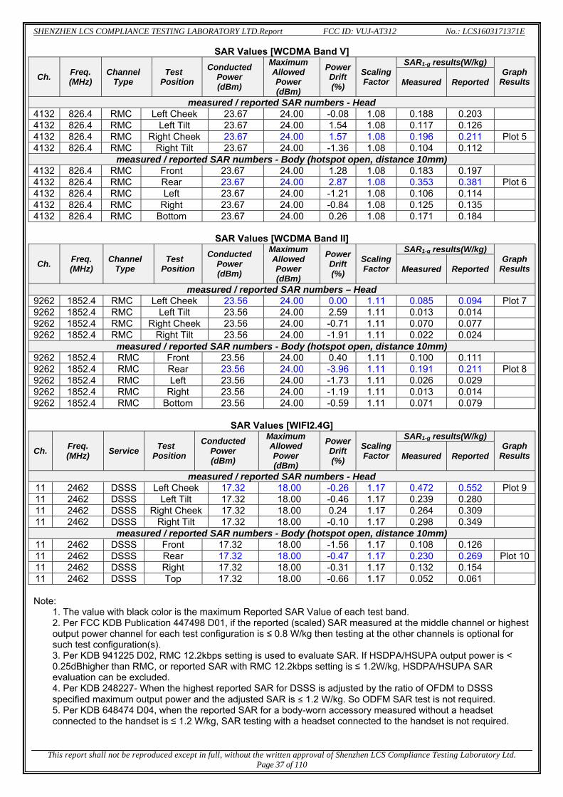
SHENZHEN LCS COMPLIANCE TESTING LABORATORY LTD.Report FCC ID: VUJ-AT312 No.: LCS1603171371E
This report shall not be reproduced except in full, without the written approval of Shenzhen LCS Compliance Testing Laboratory Ltd.
Page 37 of 110
SAR Values [WCDMA Band V]
Ch. Freq. (MHz)
Channel Type
Test Position
Conducted Power (dBm)
Maximum Allowed Power (dBm)
PowerDrift (%)
ScalingFactor
SAR1-g results(W/kg)Graph
ResultsMeasured Reported
measured / reported SAR numbers - Head 4132 826.4 RMC Left Cheek 23.67 24.00 -0.08 1.08 0.188 0.203 4132 826.4 RMC Left Tilt 23.67 24.00 1.54 1.08 0.117 0.126 4132 826.4 RMC Right Cheek 23.67 24.00 1.57 1.08 0.196 0.211 Plot 54132 826.4 RMC Right Tilt 23.67 24.00 -1.36 1.08 0.104 0.112
measured / reported SAR numbers - Body (hotspot open, distance 10mm) 4132 826.4 RMC Front 23.67 24.00 1.28 1.08 0.183 0.197 4132 826.4 RMC Rear 23.67 24.00 2.87 1.08 0.353 0.381 Plot 64132 826.4 RMC Left 23.67 24.00 -1.21 1.08 0.106 0.114 4132 826.4 RMC Right 23.67 24.00 -0.84 1.08 0.125 0.135 4132 826.4 RMC Bottom 23.67 24.00 0.26 1.08 0.171 0.184
SAR Values [WCDMA Band II]
Ch. Freq. (MHz)
Channel Type
Test Position
Conducted Power (dBm)
Maximum Allowed Power (dBm)
PowerDrift (%)
ScalingFactor
SAR1-g results(W/kg)Graph
ResultsMeasured Reported
measured / reported SAR numbers – Head 9262 1852.4 RMC Left Cheek 23.56 24.00 0.00 1.11 0.085 0.094 Plot 79262 1852.4 RMC Left Tilt 23.56 24.00 2.59 1.11 0.013 0.014 9262 1852.4 RMC Right Cheek 23.56 24.00 -0.71 1.11 0.070 0.077 9262 1852.4 RMC Right Tilt 23.56 24.00 -1.91 1.11 0.022 0.024
measured / reported SAR numbers - Body (hotspot open, distance 10mm) 9262 1852.4 RMC Front 23.56 24.00 0.40 1.11 0.100 0.111 9262 1852.4 RMC Rear 23.56 24.00 -3.96 1.11 0.191 0.211 Plot 89262 1852.4 RMC Left 23.56 24.00 -1.73 1.11 0.026 0.029 9262 1852.4 RMC Right 23.56 24.00 -1.19 1.11 0.013 0.014 9262 1852.4 RMC Bottom 23.56 24.00 -0.59 1.11 0.071 0.079
SAR Values [WIFI2.4G]
Ch. Freq. (MHz) Service Test
Position Conducted
Power (dBm)
Maximum Allowed Power (dBm)
PowerDrift (%)
ScalingFactor
SAR1-g results(W/kg)Graph
ResultsMeasured Reported
measured / reported SAR numbers - Head 11 2462 DSSS Left Cheek 17.32 18.00 -0.26 1.17 0.472 0.552 Plot 911 2462 DSSS Left Tilt 17.32 18.00 -0.46 1.17 0.239 0.280 11 2462 DSSS Right Cheek 17.32 18.00 0.24 1.17 0.264 0.309 11 2462 DSSS Right Tilt 17.32 18.00 -0.10 1.17 0.298 0.349
measured / reported SAR numbers - Body (hotspot open, distance 10mm) 11 2462 DSSS Front 17.32 18.00 -1.56 1.17 0.108 0.126 11 2462 DSSS Rear 17.32 18.00 -0.47 1.17 0.230 0.269 Plot 1011 2462 DSSS Right 17.32 18.00 -0.31 1.17 0.132 0.154 11 2462 DSSS Top 17.32 18.00 -0.66 1.17 0.052 0.061
Note:
1. The value with black color is the maximum Reported SAR Value of each test band. 2. Per FCC KDB Publication 447498 D01, if the reported (scaled) SAR measured at the middle channel or highest output power channel for each test configuration is ≤ 0.8 W/kg then testing at the other channels is optional for such test configuration(s). 3. Per KDB 941225 D02, RMC 12.2kbps setting is used to evaluate SAR. If HSDPA/HSUPA output power is < 0.25dBhigher than RMC, or reported SAR with RMC 12.2kbps setting is ≤ 1.2W/kg, HSDPA/HSUPA SAR evaluation can be excluded. 4. Per KDB 248227- When the highest reported SAR for DSSS is adjusted by the ratio of OFDM to DSSS specified maximum output power and the adjusted SAR is ≤ 1.2 W/kg. So ODFM SAR test is not required. 5. Per KDB 648474 D04, when the reported SAR for a body-worn accessory measured without a headset connected to the handset is ≤ 1.2 W/kg, SAR testing with a headset connected to the handset is not required.

SHENZHEN LCS COMPLIANCE TESTING LABORATORY LTD.Report FCC ID: VUJ-AT312 No.: LCS1603171371E
This report shall not be reproduced except in full, without the written approval of Shenzhen LCS Compliance Testing Laboratory Ltd.
Page 38 of 110
5.3.3 Standalone SAR Test Exclusion Considerations and Estimated SAR Per KDB447498 requires when the standalone SAR test exclusion of section 4.3.1 is applied to an antenna that transmits simultaneously with other antennas, the standalone SAR must be estimated according to the following to determine simultaneous transmission SAR test exclusion; (max. power of channel, including tune-up tolerance, mW)/(min. test separation distance, mm)]·[√f(GHz)/x] W/kg for test separation distances ≤ 50 mm; where x = 7.5 for 1-g SAR, and x = 18.75 for 10-g SAR. 0.4 W/kg for 1-g SAR and 1.0 W/kg for 10-g SAR, when the test separation distances is > 50 mm Per FCC KD B447498 D01,simultaneous transmission SAR test exclusion may be applied when the sum of the 1-g SAR for all the transmitting antenna in a specific a physical test configuration is ≤1.6 W/Kg.When the sum is greater than the SAR limit,SAR test exclusion is determined by the SAR to peak location separation ratio.
1.51 2(SAR +SAR )Ratio= 0.04
(peak location separation,mm)<
Estimated stand alone SAR
Communication system
Frequency(MHz) Configuration
Maximum Power (including tune-up
tolerance) (dBm)
Separation Distance
(mm)
Estimated SAR1-g (W/kg)
Bluetooth* 2450 Head 5.0 5 0.132 Bluetooth* 2450 Hotspot 5.0 10 0.066 Bluetooth* 2450 Body-worn 5.0 10 0.066
Remark:
1. Bluetooth*- Including Lower power Bluetooth 2. Maximum average power including tune-up tolerance; 3. When the minimum test separation distance is < 5 mm, a distance of 5 mm is applied to determine
SAR test exclusion 4. Body as body use distance is 10mm from manufacturer declaration of user manual.

SHENZHEN LCS COMPLIANCE TESTING LABORATORY LTD.Report FCC ID: VUJ-AT312 No.: LCS1603171371E
This report shall not be reproduced except in full, without the written approval of Shenzhen LCS Compliance Testing Laboratory Ltd.
Page 39 of 110
4.5. Simultaneous TX SAR Considerations 4.5.1 Introduction The following procedures adopted from “FCC SAR Considerations for Cell Phones with Multiple Transmitters” are applicable to handsets with built-in unlicensed transmitters such as 802.11 a/b/g/n and Bluetooth devices which may simultaneously transmit with the licensed transmitter. For the DUT,the BT and WiFi modules sharing same antenna, GSM/WCDMA modules sharing a single antenna; Application Simultaneous Transmission information:
Air-Interface Band (MHz) Type Simultaneous Transmissions Voice over
Digital Transport(Data)
GSM 850 VO Yes,WLAN or BT N/A 1900 VO
GPRS/EDGE DT Yes,WLAN or BT N/A WCDMA Band II/ BandV DT Yes,WLAN or BT N/A WLAN 2450 DT Yes,GSM,GPRS,EDGE,UMTS Yes
BT 2450 DT Yes,GSM,GPRS,EDGE,UMTS N/A Note:VO-Voice Service only;DT-Digital Transport
Note: BT and WLAN can be active at the same time, but only with interleaving of packages switched on board level. That means that they don’t transmit at the same time. BLE-Bluetooth low energy; BT- Classical Bluetooth
4.5.2 Evaluation of Simultaneous SAR Head Exposure Conditions
Simultaneous transmission SAR for WiFi and GSM
Test Position
GSM850 Reported SAR1-g (W/Kg)
GSM1900 Reported SAR1-g (W/Kg)
WiFi2.4G Reported SAR1-g (W/Kg)
MAX. ΣSAR1-g (W/Kg)
SAR1-g Limit
(W/Kg)
Peak location separation
ratio Simut Meas.
Required
Left Cheek 0.442 0.133 0.552 0.994 1.6 no no Left Tilt 0.251 0.020 0.280 0.531 1.6 no no
Right Cheek 0.527 0.070 0.309 0.836 1.6 no no Right Tilt 0.264 0.039 0.349 0.613 1.6 no no
Simultaneous transmission SAR for WiFi and UMTS
Test Position
UMTS Band V Reported SAR1-g
(W/Kg)
UMTS Band II Reported SAR1-g
(W/Kg)
WiFi2.4G Reported SAR1-g (W/Kg)
MAX. ΣSAR1-g (W/Kg)
SAR1-g Limit
(W/Kg)
Peak location separation
ratio Simut Meas.
Required
Left Cheek 0.203 0.094 0.552 0.755 1.6 no no Left Tilt 0.126 0.014 0.280 0.406 1.6 no no
Right Cheek 0.211 0.077 0.309 0.520 1.6 no no Right Tilt 0.112 0.024 0.349 0.461 1.6 no no
Simultaneous transmission SAR for BT and GSM
Test Position
GSM850 Reported SAR1-g (W/Kg)
GSM1900 Reported SAR1-g (W/Kg)
BT Estimated SAR1-g (W/Kg)
MAX. ΣSAR1-g (W/Kg)
SAR1-g Limit
(W/Kg)
Peak location separation
ratio Simut Meas.
Required
Left Cheek 0.442 0.133 0.132 0.574 1.6 no no Left Tilt 0.251 0.020 0.132 0.383 1.6 no no
Right Cheek 0.527 0.070 0.132 0.659 1.6 no no Right Tilt 0.264 0.039 0.132 0.396 1.6 no no

SHENZHEN LCS COMPLIANCE TESTING LABORATORY LTD.Report FCC ID: VUJ-AT312 No.: LCS1603171371E
This report shall not be reproduced except in full, without the written approval of Shenzhen LCS Compliance Testing Laboratory Ltd.
Page 40 of 110
Simultaneous transmission SAR for BT and UMTS
Test Position
UMTS Band V Reported SAR1-g
(W/Kg)
UMTS Band II Reported SAR1-g
(W/Kg)
BTEstimated
SAR1-g (W/Kg)
MAX. ΣSAR1-g (W/Kg)
SAR1-g Limit
(W/Kg)
Peak location separation
ratio Simut Meas.
Required
Left Cheek 0.203 0.094 0.132 0.335 1.6 no no Left Tilt 0.126 0.014 0.132 0.258 1.6 no no
Right Cheek 0.211 0.077 0.132 0.343 1.6 no no Right Tilt 0.112 0.024 0.132 0.244 1.6 no no
Body Hotspot Exposure Conditions
Simultaneous transmission SAR for WiFi and GSM
Test Position
GSM850 Reported SAR1-g (W/Kg)
GSM1900 Reported SAR1-g (W/Kg)
WiFi2.4GReported
SAR1-g (W/Kg)
MAX. ΣSAR1-g (W/Kg)
SAR1-g Limit
(W/Kg)
Peak location separation
ratio Simut Meas.
Required
Front 0.517 0.106 0.126 0.643 1.6 no no Rear 0.904 0.252 0.269 1.173 1.6 no no Left 0.341 0.037 / 0.341 1.6 no no
Right 0.459 0.018 0.154 0.613 1.6 no no Bottom 0.138 0.042 / 0.138 1.6 no no
Top / / 0.061 0.061 1.6 no no
Simultaneous transmission SAR for WiFi and UMTS
Test Position
UMTS Band V Reported SAR1-g
(W/Kg)
UMTS Band II Reported SAR1-g
(W/Kg)
WiFi2.4GReported
SAR1-g (W/Kg)
MAX. ΣSAR1-g (W/Kg)
SAR1-g Limit
(W/Kg)
Peak location separation
ratio Simut Meas.
Required
Front 0.197 0.111 0.126 0.323 1.6 no no Rear 0.353 0.191 0.269 0.622 1.6 no no Left 0.114 0.029 / 0.114 1.6 no no
Right 0.135 0.014 0.154 0.289 1.6 no no Bottom 0.184 0.079 / 0.184 1.6 no no
Top / / 0.061 0.061 1.6 no no
Simultaneous transmission SAR for BT and GSM
Test Position
GSM850 Reported SAR1-g (W/Kg)
GSM1900 Reported SAR1-g (W/Kg)
BTEstimated
SAR1-g (W/Kg)
MAX. ΣSAR1-g (W/Kg)
SAR1-g Limit
(W/Kg)
Peak location separation
ratio Simut Meas.
Required
Front 0.517 0.106 0.066 0.583 1.6 no no Rear 0.904 0.252 0.066 0.970 1.6 no no Left 0.341 0.037 / 0.341 1.6 no no
Right 0.459 0.018 0.066 0.525 1.6 no no Bottom 0.138 0.042 / 0.138 1.6 no no
Top / / 0.066 0.066 1.6 no no
Simultaneous transmission SAR for BT and UMTS
Test Position
UMTS Band V Reported SAR1-g
(W/Kg)
UMTS Band II Reported SAR1-g
(W/Kg)
BTEstimated
SAR1-g (W/Kg)
MAX. ΣSAR1-g (W/Kg)
SAR1-g Limit
(W/Kg)
Peak location separation
ratio Simut Meas.
Required
Front 0.197 0.111 0.066 0.263 1.6 no no Rear 0.353 0.191 0.066 0.419 1.6 no no Left 0.114 0.029 / 0.114 1.6 no no
Right 0.135 0.014 0.066 0.201 1.6 no no Bottom 0.184 0.079 / 0.184 1.6 no no
Top / / 0.066 0.066 1.6 no no
Note: 1. The WiFi and BT share same antenna, so cannot transmit at same time. 2. The value with block color is the maximum values of standalone 3. The value with blue color is the maximum values of ∑SAR1-g

SHENZHEN LCS COMPLIANCE TESTING LABORATORY LTD.Report FCC ID: VUJ-AT312 No.: LCS1603171371E
This report shall not be reproduced except in full, without the written approval of Shenzhen LCS Compliance Testing Laboratory Ltd.
Page 41 of 110
4.6. SAR Measurement Variability According to KDB865664, Repeated measurements are required only when the measured SAR is ≥ 0.80 W/kg. If the measured SAR value of the initial repeated measurement is < 1.45 W/kg with ≤ 20% variation, only one repeated measurement is required to reaffirm that the results are not expected to have substantial variations, which may introduce significant compliance concerns. A second repeated measurement is required only if the measured result for the initial repeated measurement is within 10% of the SAR limit and vary by more than 20%, which are often related to device and measurement setup difficulties. The following procedures are applied to determine if repeated measurements are required. The same procedures should be adapted for measurements according to extremity and occupational exposure limits by applying a factor of 2.5 for extremity exposure and a factor of 5 for occupational exposure to the corresponding SAR thresholds.19 The repeated measurement results must be clearly identified in the SAR report. All measured SAR, including the repeated results, must be considered to determine compliance and for reporting according to KDB 690783.Repeated measurement is not required when the original highest measured SAR is < 0.80 W/kg; steps 2) through 4) do not apply. 3) When the original highest measured SAR is ≥ 0.80 W/kg, repeat that measurement once. 4) Perform a second repeated measurement only if the ratio of largest to smallest SAR for the original and first
repeated measurements is > 1.20 or when the original or repeated measurement is ≥ 1.45 W/kg (~ 10% from the 1-g SAR limit).
5) Perform a third repeated measurement only if the original, first or second repeated measurement is ≥ 1.5 W/kg and the ratio of largest to smallest SAR for the original, first and second repeated measurements is > 1.20.
6) Perform a third repeated measurement only if the original, first or second repeated measurement is ≥ 1.5 W/kg and the ratio of largest to smallest SAR for the original, first and second repeated measurements is > 1.20
Frequency Band Air Interface
RF Exposure
Configuration
Test Position
RepeatedSAR
(yes/no)
Highest Measured
SAR1-g (W/Kg)
First Repeated
Measued SAR1-g (W/Kg)
Largest to
Smallest SAR Ratio
850 GSM850 Standalone Body-Rear no 0.766 n/a n/a WCDMA Band V Standalone Body-Rear no 0.226 n/a n/a
1900 GSM1900 Standalone Body-Rear no 0.196 n/a n/a WCDMA Band II Standalone Body-Rear no 0.191 n/a n/a
2450 2.4GWLAN Standalone Head-Left Check no 0.472 n/a n/a
Remark: 1. Second Repeated Measurement is not required since the ratio of the largest to smallest SAR for the orignal and
first repeated measurement is not > 1.20 or 3 (1-g or 10-g respectively)
4.7. General description of test procedures 1. The DUT is tested using CMU 200 communications testers as controller unit to set test channels and
maximum output power to the DUT, as well as for measuring the conducted peak power. 2. Test positions as described in the tables above are in accordance with the specified test standard. 3. Tests in body position were performed in that configuration, which generates the highest time based
averaged output power (see conducted power results). 4. Tests in head position with GSM were performed in voice mode with 1 timeslot unless
GPRS/EGPRS/DTM function allows parallel voice and data traffic on 2 or more timeslots. 5. UMTS was tested in RMC mode with 12.2 kbit/s and TPC bits set to ‘all 1’. 6. WiFi was tested in 802.11b/g/n mode with 1 Mbit/s and 6 Mbit/s. According to KDB 248227 the SAR
testing for 802.11g/n is not required since When the highest reported SAR for DSSS is adjusted by the ratio of OFDM to DSSS specified maximum output power and the adjusted SAR is ≤ 1.2 W/kg.
7. Required WiFi test channels were selected according to KDB 248227 8. According to FCC KDB 941225 D06 this device has been tested with 10 mm distance to the phantom for
operation in WiFi hot spot mode. 9. Per FCC KDB 941225 D06 the edges with antennas within 2.5 cm are required to be evaluated for SAR
to cover WiFi hot spot function.

SHENZHEN LCS COMPLIANCE TESTING LABORATORY LTD.Report FCC ID: VUJ-AT312 No.: LCS1603171371E
This report shall not be reproduced except in full, without the written approval of Shenzhen LCS Compliance Testing Laboratory Ltd.
Page 42 of 110
10. According to KDB 447498 D01 testing of other required channels within the operating mode of a frequency band is not required when the reported 1-g or 10-g SAR for the mid-band or highest output power channel is: ≤ 0.8 W/kg or 2.0 W/kg, for 1-g or 10-g respectively, when the transmission band is ≤ 100 MHz ≤ 0.6 W/kg or 1.5 W/kg, for 1-g or 10-g respectively, when the transmission band is between 100 MHz and 200 MHz ≤ 0.4 W/kg or 1.0 W/kg, for 1-g or 10-g respectively, when the transmission band is ≥ 200 MHz
11. Per KDB648474 D04 require when the reported SAR for a body-worn accessory, measured without a headset connected to the handset, is < 1.2 W/kg.
12. Per KDB648474 D04 require when the separation distance required for body-worn accessory testing is larger than or equal to that tested for hotspot mode, using the same wireless mode test configuration for voice and data, such as UMTS, LTE and Wi-Fi, and for the same surface of the phone, the hotspot mode SAR data may be used to support body-worn accessory SAR compliance for that particular configuration (surface)
13. Per KDB648474 D04 require for phablet SAR test considerations,For Mobile Phones with a display diagonal dimension > 15.0 cm or an overall diagonal dimension > 16.0 cm, When hotspot mode applies, 10-g extremity SAR is required only for the surfaces and edges with hotspot mode 1-g reported SAR > 1.2 W/kg.
14. 10-g extremity SAR is required only for the surfaces and edges with hotspot mode 1-g SAR > 1.2 W/kg.
4.8. Measurement Uncertainty (300MHz-6GHz) Not required as SAR measurement uncertainty analysis is required in SAR reports only when the highest measured SAR in a frequency band is ≥ 1.5 W/kg for 1-g SAR accoridng to KDB865664D01.

SHEN
T
NZHEN LCS CO
This report shal
4.9. Syst Test modeProduct DeModel:DipE-Field ProTest Date:
R
OMPLIANCE T
ll not be reprod
tem Check
e:835MHz(escription:ole SID835obe:SSE5: April 18,
MediumFrequ
Relative permCondu
InpCre
ConveVar
SAR SAR
SURF
TESTING LABO
duced except in
k Results
(Head) Validation 5 (SN17/14 2016
m(liquid typuency (MHzmittivity (re
uctivity (S/mput power est Factor ersion Factoriation (%) 10g (W/Kg
R 1g (W/Kg)FACE SAR
ORATORY LTD
n full, without t
EP221)
pe) z) eal part) m)
or
g) ) R
D.Report
the written appPage 43 of 110
FCC ID:
proval of Shenzh0
VUJ-AT312
hen LCS Comp
HSL835.0
420.
1001
4.0.4500.6270.943
VOLUM
No.
pliance Testing
L_850 000000 2.63 .91 0mW 1.0 .83 00000 76352 34241 ME SAR
: LCS16031713
g Laboratory Lt
371E
td.
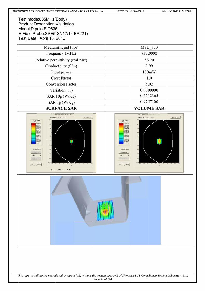
SHEN
T
NZHEN LCS CO
This report shal
Test modeProduct DeModel:DipE-Field ProTest Date:
R
OMPLIANCE T
ll not be reprod
e:835MHz(escription:ole SID835obe:SSE5: April 18,
MediumFrequ
Relative permCondu
InpCre
ConveVar
SAR SAR
SURF
TESTING LABO
duced except in
(Body) Validation 5 (SN17/14 2016
m(liquid typuency (MHzmittivity (re
uctivity (S/mput power est Factor ersion Factoriation (%) 10g (W/Kg
R 1g (W/Kg)FACE SAR
ORATORY LTD
n full, without t
EP221)
pe) z) eal part) m)
or
g) ) R
D.Report
the written appPage 44 of 110
FCC ID:
proval of Shenzh0
VUJ-AT312
hen LCS Comp
MSL835.
530.
1001
5.0.9600.6210.975
VOLUM
No.
pliance Testing
L_850 .0000
3.20 .99 0mW 1.0 .02 00000 12365 57100 ME SAR
: LCS16031713
g Laboratory Lt
371E
td.

SHEN
T
NZHEN LCS CO
This report shal
Test modeProduct DeModel:DipE-Field ProTest Date:
R
OMPLIANCE T
ll not be reprod
e:835MHz(escription:ole SID835obe:SSE5: July 19, 2
MediumFrequ
Relative permCondu
InpCre
ConveVar
SAR SAR
SURF
TESTING LABO
duced except in
(Body) Validation 5 (SN17/14 2016
m(liquid typuency (MHzmittivity (re
uctivity (S/mput power est Factor ersion Factoriation (%) 10g (W/Kg
R 1g (W/Kg)FACE SAR
ORATORY LTD
n full, without t
EP221)
pe) z) eal part) m)
or
g) ) R
D.Report
the written appPage 45 of 110
FCC ID:
proval of Shenzh0
VUJ-AT312
hen LCS Comp
MSL835.
561.
1001
5.-0.120.610.95
VOLUM
No.
pliance Testing
L_850 .0000
6.81 .01 0mW 1.0 .02 20000 17053 52272 ME SAR
: LCS16031713
g Laboratory Lt
371E
td.

SHEN
T
NZHEN LCS CO
This report shal
Test modeProduct DeModel :DipE-Field ProTest Date:
R
OMPLIANCE T
ll not be reprod
e:1900MHzescription:pole SID19obe:SSE5: April 19, 2
MediumFrequ
Relative permCondu
InpCre
ConveVar
SAR SAR
SURF
TESTING LABO
duced except in
z(Head) Validation
900 (SN17/14 2016
m(liquid typuency (MHzmittivity (re
uctivity (S/mput power est Factor ersion Factoriation (%) 10g (W/Kg
R 1g (W/Kg)FACE SAR
ORATORY LTD
n full, without t
EP221)
pe) z) eal part) m)
or
g) ) R
D.Report
the written appPage 46 of 110
FCC ID:
proval of Shenzh0
VUJ-AT312
hen LCS Comp
HSL_1900
411.
1001
4.-1.282.0734.008
VOLUM
No.
pliance Testing
_1900 0.0000 1.25 .44 0mW 1.0 .71 00000 30962 86846 ME SAR
: LCS16031713
g Laboratory Lt
371E
td.

SHEN
T
NZHEN LCS CO
This report shal
Test modeProduct DeModel :DipE-Field ProTest Date:
R
OMPLIANCE T
ll not be reprod
e:1900MHzescription:pole SID19obe:SSE5: April 19, 2
MediumFrequ
Relative permCondu
InpCre
ConveVar
SAR SAR
SURF
TESTING LABO
duced except in
z(Body) Validation
900 (SN17/14 2016
m(liquid typuency (MHzmittivity (re
uctivity (S/mput power est Factor ersion Factoriation (%) 10g (W/Kg
R 1g (W/Kg)FACE SAR
ORATORY LTD
n full, without t
EP221)
pe) z) eal part) m)
or
g) ) R
D.Report
the written appPage 47 of 110
FCC ID:
proval of Shenzh0
VUJ-AT312
hen LCS Comp
MSL_1900
541.
1001
4.0.0702.1644.230
VOLUM
No.
pliance Testing
L_1900 0.0000 4.41 .53 0mW 1.0 .85 00000 48026 06621 ME SAR
: LCS16031713
g Laboratory Lt
371E
td.

SHEN
T
NZHEN LCS CO
This report shal
Test modeProduct DeModel :DipE-Field ProTest Date:
R
OMPLIANCE T
ll not be reprod
e:1900MHzescription:pole SID19obe:SSE5: July 19, 2
MediumFrequ
Relative permCondu
InpCre
ConveVar
SAR SAR
SURF
TESTING LABO
duced except in
z(Body) Validation
900 (SN17/14
2016
m(liquid typuency (MHzmittivity (re
uctivity (S/mput power est Factor ersion Factoriation (%) 10g (W/Kg
R 1g (W/Kg)FACE SAR
ORATORY LTD
n full, without t
EP221)
pe) z) eal part) m)
or
g) ) R
D.Report
the written appPage 48 of 110
FCC ID:
proval of Shenzh0
VUJ-AT312
hen LCS Comp
MSL_1900
551.
1001
4.-0.452.274.58
VOLUM
No.
pliance Testing
L_1900 0.0000 5.06 .54 0mW 1.0 .85 50000 78695 86885 ME SAR
: LCS16031713
g Laboratory Lt
371E
td.

SHEN
T
NZHEN LCS CO
This report shal
Test modeProduct DeModel:DipE-Field ProTest Date:
R
OMPLIANCE T
ll not be reprod
e:2450MHzescription:ole SID245obe:SSE5: April 20, 2
MediumFrequ
Relative permCondu
InpCre
ConveVar
SAR SAR
SURF
TESTING LABO
duced except in
z(Head) Validation 50 (SN17/14 2016
m(liquid typuency (MHzmittivity (re
uctivity (S/mput power est Factor ersion Factoriation (%) 10g (W/Kg
R 1g (W/Kg)FACE SAR
ORATORY LTD
n full, without t
EP221)
pe) z) eal part) m)
or
g) ) R
D.Report
the written appPage 49 of 110
FCC ID:
proval of Shenzh0
VUJ-AT312
hen LCS Comp
HSL_2450.0
391.
1001
4.-1.362.3465.035
VOLUM
No.
pliance Testing
_2450 000000
9.14 .80 0mW 1.0 .11
600000 61573 57281 ME SAR
: LCS16031713
g Laboratory Lt
371E
td.

SHEN
T
NZHEN LCS CO
This report shal
Test modeProduct DeModel:DipE-Field ProTest Date:
R
OMPLIANCE T
ll not be reprod
e:2450MHzescription:ole SID245obe:SSE5: April 20, 2
MediumFrequ
Relative permCondu
InpCre
ConveVar
SAR SAR
SURF
TESTING LABO
duced except in
z(Body) Validation 50 (SN17/14 2016
m(liquid typuency (MHzmittivity (re
uctivity (S/mput power est Factor ersion Factoriation (%) 10g (W/Kg
R 1g (W/Kg)FACE SAR
ORATORY LTD
n full, without t
EP221)
pe) z) eal part) m)
or
g) ) R
D.Report
the written appPage 50 of 110
FCC ID:
proval of Shenzh0
VUJ-AT312
hen LCS Comp
MSL_2450.0
521.
1001
4.-2.042.4385.198
VOLUM
No.
pliance Testing
L_2450 000000
2.72 .91 0mW 1.0 .25
400000 85573 87281 ME SAR
: LCS16031713
g Laboratory Lt
371E
td.

SHEN
T
SARfreq#1
NZHEN LCS CO
This report shal
4.10. SARR plots for quency ban
Test ModeProduct DModel: ATTest Date
R
OMPLIANCE T
ll not be reprod
R Test Grathe highes
nd combina
e:GSM 850Description:T312 : April 18,
MediumFrequ
Relative perCondu
E-FCr
Conve
AZo
VarSAR SAR
SURF
TESTING LABO
duced except in
ph Resultst measureation acco
0MHz,High: 3G Smart
2016
m(liquid typuency (MHzrmittivity (reuctivity (S/mField Probe rest Factor ersion FactoSensor
Area Scan oom Scan riation (%) 10g (W/Kg
R 1g (W/Kg)FACE SA
ORATORY LTD
n full, without t
ts ed SAR in rding to FC
h channel(Ht phone
pe) z) eal part) m)
or
g) ) R
D.Report
the written appPage 51 of 110
each expoCC KDB 86
Head Righ
FCC ID:
proval of Shenzh0
osure confi65664 D02
t Cheek)
5x5x
VUJ-AT312
hen LCS Comp
guration, w2
MSL848.8
420
SN 17/8
44m
dx=8mm7,dx=8mm
-2.50.340.46
VOLUM
No.
pliance Testing
wireless mo
L_850 800000 2.81
0.89 /14 EP221 8.0
4.83 4mm m dy=8mm dy=8mm d
570000 44655 69470
UME SAR
: LCS16031713
g Laboratory Lt
ode and
dz=5mm
371E
td.

SHEN
T
#2
NZHEN LCS CO
This report shal
Test ModeProduct DModel: ATTest Date
R
OMPLIANCE T
ll not be reprod
e: Hotspot Description:T312 : July 19,
MediumFrequ
Relative perCondu
E-FCr
Conve
AZo
VarSAR SARSUR
TESTING LABO
duced except in
GSM850M: 3G Smar
2016
m(liquid typuency (MHzrmittivity (reuctivity (S/mField Probe rest Factor ersion FactoSensor
Area Scan oom Scan riation (%) 10g (W/Kg
R 1g (W/Kg)RFACE SAR
ORATORY LTD
n full, without t
MHz,Mid cht phone
pe) z) eal part) m)
or
g) )
R
D.Report
the written appPage 52 of 110
hannel(Bod
FCC ID:
proval of Shenzh0
dy Rear Sid
5x5x
VUJ-AT312
hen LCS Comp
de)
MSL836.6
561
SN 17/654m
dx=8mm7,dx=8mm
3.710.550.76
VOLU
No.
pliance Testing
L_850 600000 6.81
1.01 /14 EP221 6.02 5.02 4mm m dy=8mm dy=8mm d10000 53652 65763
UME SAR
: LCS16031713
g Laboratory Lt
dz=5mm
371E
td.

SHEN
T
#3
NZHEN LCS CO
This report shal
Test ModeProduct DModel: ATTest Date
R
OMPLIANCE T
ll not be reprod
e:GSM 190Description:T312 : April 19,
MediumFrequ
Relative permCondu
E-FCre
Conve
AZo
VarSAR SAR
SURF
TESTING LABO
duced except in
00MHz,Mid: 3G Smar
2016
m(liquid typuency (MHzmittivity (re
uctivity (S/mField Probe est Factor ersion FactoSensor
Area Scan oom Scan riation (%) 10g (W/Kg
R 1g (W/Kg)FACE SAR
ORATORY LTD
n full, without t
d channel(t phone
pe) z) eal part) m)
or
g) ) R
D.Report
the written appPage 53 of 110
(Head Left
FCC ID:
proval of Shenzh0
Cheek)
5x5x7
VUJ-AT312
hen LCS Comp
MSL_1880.0
411.
SN17/18
4.4m
dx=8mm7,dx=8mm d
-1.160.060.11
VOLUM
No.
pliance Testing
L_1900 000000
1.09 .42 4 EP221
8.0 .71 mm
m dy=8mm dy=8mm dz60000 64949 17692 ME SAR
: LCS16031713
g Laboratory Lt
z=5mm
371E
td.

SHEN
T
#4
NZHEN LCS CO
This report shal
Test ModeProduct DModel: ATTest Date
R
OMPLIANCE T
ll not be reprod
e: Hotspot Description:T312 : July 19, 2
MediumFrequ
Relative permCondu
E-FCre
Conve
AZo
VarSAR SAR
SURF
TESTING LABO
duced except in
GPRS190: 3G Smar
2016
m(liquid typuency (MHzmittivity (re
uctivity (S/mField Probe est Factor ersion FactoSensor
Area Scan oom Scan riation (%) 10g (W/Kg
R 1g (W/Kg)FACE SAR
ORATORY LTD
n full, without t
00MHz,Midt phone
pe) z) eal part) m)
or
g) ) R
D.Report
the written appPage 54 of 110
d channel(B
FCC ID:
proval of Shenzh0
Body Rear
5x5x7
VUJ-AT312
hen LCS Comp
r Side)
MSL_1880.0
551.
SN17/14.4.4m
dx=8mm7,dx=8mm d
1.320.160.22
VOLUM
No.
pliance Testing
L_1900 000000
5.71 .53 4 EP221 .06 .85 mm
m dy=8mm dy=8mm dz20000 65221 26403 ME SAR
: LCS16031713
g Laboratory Lt
z=5mm
371E
td.
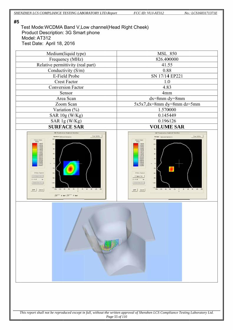
SHEN
T
#5
NZHEN LCS CO
This report shal
Test ModeProduct DModel: ATTest Date
Rel
OMPLIANCE T
ll not be reprod
e:WCDMA Description:T312 : April 18,
Medium(Frequen
lative permConduct
E-FieCres
ConversSe
AreZoom
VariaSAR 10SAR 1
SURFA
TESTING LABO
duced except in
Band V,Lo: 3G Smar
2016
(liquid typency (MHz)
mittivity (reativity (S/m)
eld Probe t Factor sion Factor ensor ea Scan m Scan
ation (%) 0g (W/Kg) g (W/Kg)
ACE SAR
ORATORY LTD
n full, without t
ow channet phone
)
l part)
D.Report
the written appPage 55 of 110
el(Head Rig
FCC ID:
proval of Shenzh0
ght Cheek
5x5x7,d
VUJ-AT312
hen LCS Comp
)
MSL_826.40
41.50.8
SN 17/141.0
4.84mm
dx=8mm ddx=8mm dy
1.5700.1450.196
VOLUM
No.
pliance Testing
_850 00000 55
88 4 EP221 0
83 m dy=8mm y=8mm dz=0000 5449 6126
ME SAR
: LCS16031713
g Laboratory Lt
=5mm
371E
td.

SHEN
T
#6
NZHEN LCS CO
This report shal
Test ModeProduct DeModel: ATTest Date
Rel
OMPLIANCE T
ll not be reprod
e: Hotspot escription:
T312 : July 19,
Medium(Frequen
lative permConduct
E-FieCres
ConversSe
AreZoom
VariaSAR 10SAR 1
SURFA
TESTING LABO
duced except in
WCDMA B 3G Smart
2016
(liquid typency (MHz)
mittivity (reativity (S/m)
eld Probe t Factor sion Factor ensor ea Scan m Scan
ation (%) 0g (W/Kg) g (W/Kg)
ACE SAR
ORATORY LTD
n full, without t
Band V,Lowt phone
)
l part)
D.Report
the written appPage 56 of 110
w channel(
FCC ID:
proval of Shenzh0
(Body Rea
5x5x7,d
VUJ-AT312
hen LCS Comp
ar Side)
MSL_826.40
53.70.9
SN 17/141.0
5.04mm
dx=8mm ddx=8mm dy
2.8700.2120.353
VOLUM
No.
pliance Testing
_850 00000 78
98 4 EP221 0
02 m dy=8mm y=8mm dz=0000 2730 3073
ME SAR
: LCS16031713
g Laboratory Lt
=5mm
371E
td.

SHEN
T
#7
NZHEN LCS CO
This report shal
Test ModeProduct DModel: ATTest Date
Re
OMPLIANCE T
ll not be reprod
e:WCDMADescription:T312 : April 19,
Medium(Frequen
elative permConduct
E-FieCres
ConverSe
AreZoo
VariaSAR 10SAR 1
SURFA
TESTING LABO
duced except in
A Band II,Lo: 3G Smart
2016
(liquid typency (MHz)
mittivity (reativity (S/m)eld Probe st Factor sion Factor ensor ea Scan om Scan ation (%) 0g (W/Kg)
1g (W/Kg) ACE SAR
ORATORY LTD
n full, without t
ow channet phone
e)
al part) )
R
D.Report
the written appPage 57 of 110
el(Head Le
FCC ID:
proval of Shenzh0
eft Cheek)
5x5x7,d
VUJ-AT312
hen LCS Comp
MSL_11852.40
40.31.42
SN17/14 1.0
4.74mm
dx=8mm ddx=8mm dy
0.00000.0440.0850
VOLUM
No.
pliance Testing
1900 00000 39 2 EP221
0 1 m dy=8mm y=8mm dz=000 877 087
ME SAR
: LCS16031713
g Laboratory Lt
=5mm
371E
td.

SHEN
T
#8
NZHEN LCS CO
This report shal
Test ModeProduct DModel: ATTest Date
Re
OMPLIANCE T
ll not be reprod
e: Hotspot Description:T312 : July 19, 2
Medium(Frequen
elative permConduct
E-FieCres
ConverSe
AreZoo
VariaSAR 10SAR 1
SURFA
TESTING LABO
duced except in
WCDMA B: 3G Smar
2016
(liquid typency (MHz)
mittivity (reativity (S/m)eld Probe st Factor sion Factor ensor ea Scan om Scan ation (%) 0g (W/Kg)
1g (W/Kg) ACE SAR
ORATORY LTD
n full, without t
Band II,Lowt phone
e)
al part) )
R
D.Report
the written appPage 58 of 110
w channel(
FCC ID:
proval of Shenzh0
(Body Rea
5x5x7,d
VUJ-AT312
hen LCS Comp
r Side)
MSL_11852.40
55.81.53
SN17/14 1.0
4.854mm
dx=8mm ddx=8mm dy
-3.9600.0940.190
VOLUM
No.
pliance Testing
1900 00000 81 3 EP221
0 5 m dy=8mm y=8mm dz=0000 868 867
ME SAR
: LCS16031713
g Laboratory Lt
=5mm
371E
td.

SHEN
T
#9
NZHEN LCS CO
This report shal
Test ModeProduct DModel: ATTest Date
R
OMPLIANCE T
ll not be reprod
e:802.11b(Description:T312 : April 20,
MediumFrequ
Relative permCondu
E-FCre
Conve
A Zo
VarSAR SAR
SURF
TESTING LABO
duced except in
(WiFi2.4G): 3G Smar
2016
m(liquid typuency (MHzmittivity (re
uctivity (S/mField Probe est Factor ersion FactoSensor
Area Scan oom Scan riation (%) 10g (W/Kg
R 1g (W/Kg)FACE SAR
ORATORY LTD
n full, without t
), High Chat phone
pe) z) eal part) m)
or
g) ) R
D.Report
the written appPage 59 of 110
annel(Hea
FCC ID:
proval of Shenzh0
d Left Che
5x5x7
VUJ-AT312
hen LCS Comp
eek)
MSL_2462.0
391.
SN 17/11
4.4m
dx=8mm7,dx=8mm d
-0.260.230.47
VOLUM
No.
pliance Testing
L_2450 000000
9.05 .77 14 EP221 1.0 .11 mm
m dy=8mm dy=8mm dz60000 39385 72292 ME SAR
: LCS16031713
g Laboratory Lt
z=5mm
371E
td.

SHEN
T
#10
NZHEN LCS CO
This report shal
0 Test ModeProduct DModel: ATTest Date
R
OMPLIANCE T
ll not be reprod
e: Hotspot Description:T312 : April 20,
MediumFrequ
Relative permCondu
E-FCre
Conve
AZo
VarSAR SAR
SURF
TESTING LABO
duced except in
802.11b(W: 3G Smar
2016
m(liquid typuency (MHzmittivity (re
uctivity (S/mField Probe est Factor ersion FactoSensor
Area Scan oom Scan riation (%) 10g (W/Kg
R 1g (W/Kg)FACE SAR
ORATORY LTD
n full, without t
WiFi2.4G),t phone
pe) z) eal part) m)
or
g) ) R
D.Report
the written appPage 60 of 110
High chan
FCC ID:
proval of Shenzh0
nnel ( Body
5x5x7
VUJ-AT312
hen LCS Comp
y Rear Side
MSL_2462.0
521.
SN 17/11
4.4m
dx=8mm7,dx=8mm d
-0.470.110.23
VOLUM
No.
pliance Testing
e)
L_2450 000000
2.97 .93 14 EP221 1.0 .25 mm
m dy=8mm dy=8mm dz70000 15249 30017 ME SAR
: LCS16031713
g Laboratory Lt
z=5mm
371E
td.
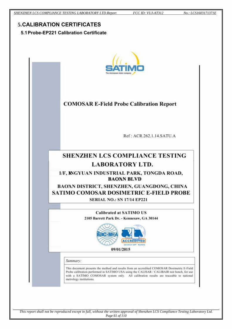
SHENZHEN LCS COMPLIANCE TESTING LABORATORY LTD.Report FCC ID: VUJ-AT312 No.: LCS1603171371E
This report shall not be reproduced except in full, without the written approval of Shenzhen LCS Compliance Testing Laboratory Ltd.
Page 61 of 110
5. CALIBRATION CERTIFICATES 5.1 Probe-EP221 Calibration Certificate

SHENZHEN LCS COMPLIANCE TESTING LABORATORY LTD.Report FCC ID: VUJ-AT312 No.: LCS1603171371E
This report shall not be reproduced except in full, without the written approval of Shenzhen LCS Compliance Testing Laboratory Ltd.
Page 62 of 110

SHENZHEN LCS COMPLIANCE TESTING LABORATORY LTD.Report FCC ID: VUJ-AT312 No.: LCS1603171371E
This report shall not be reproduced except in full, without the written approval of Shenzhen LCS Compliance Testing Laboratory Ltd.
Page 63 of 110

SHENZHEN LCS COMPLIANCE TESTING LABORATORY LTD.Report FCC ID: VUJ-AT312 No.: LCS1603171371E
This report shall not be reproduced except in full, without the written approval of Shenzhen LCS Compliance Testing Laboratory Ltd.
Page 64 of 110

SHENZHEN LCS COMPLIANCE TESTING LABORATORY LTD.Report FCC ID: VUJ-AT312 No.: LCS1603171371E
This report shall not be reproduced except in full, without the written approval of Shenzhen LCS Compliance Testing Laboratory Ltd.
Page 65 of 110

SHENZHEN LCS COMPLIANCE TESTING LABORATORY LTD.Report FCC ID: VUJ-AT312 No.: LCS1603171371E
This report shall not be reproduced except in full, without the written approval of Shenzhen LCS Compliance Testing Laboratory Ltd.
Page 66 of 110

SHENZHEN LCS COMPLIANCE TESTING LABORATORY LTD.Report FCC ID: VUJ-AT312 No.: LCS1603171371E
This report shall not be reproduced except in full, without the written approval of Shenzhen LCS Compliance Testing Laboratory Ltd.
Page 67 of 110

SHENZHEN LCS COMPLIANCE TESTING LABORATORY LTD.Report FCC ID: VUJ-AT312 No.: LCS1603171371E
This report shall not be reproduced except in full, without the written approval of Shenzhen LCS Compliance Testing Laboratory Ltd.
Page 68 of 110

SHENZHEN LCS COMPLIANCE TESTING LABORATORY LTD.Report FCC ID: VUJ-AT312 No.: LCS1603171371E
This report shall not be reproduced except in full, without the written approval of Shenzhen LCS Compliance Testing Laboratory Ltd.
Page 69 of 110

SHENZHEN LCS COMPLIANCE TESTING LABORATORY LTD.Report FCC ID: VUJ-AT312 No.: LCS1603171371E
This report shall not be reproduced except in full, without the written approval of Shenzhen LCS Compliance Testing Laboratory Ltd.
Page 70 of 110
5.2 SID835Dipole Calibration Ceriticate

SHENZHEN LCS COMPLIANCE TESTING LABORATORY LTD.Report FCC ID: VUJ-AT312 No.: LCS1603171371E
This report shall not be reproduced except in full, without the written approval of Shenzhen LCS Compliance Testing Laboratory Ltd.
Page 71 of 110

SHENZHEN LCS COMPLIANCE TESTING LABORATORY LTD.Report FCC ID: VUJ-AT312 No.: LCS1603171371E
This report shall not be reproduced except in full, without the written approval of Shenzhen LCS Compliance Testing Laboratory Ltd.
Page 72 of 110
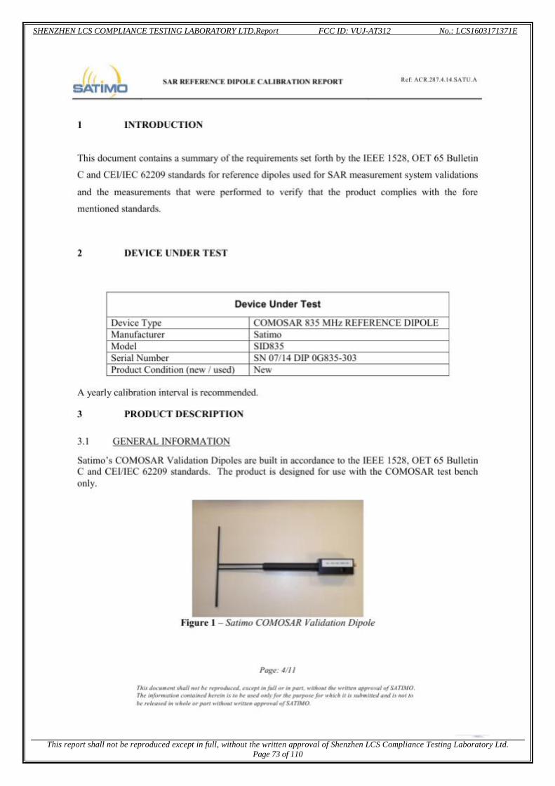
SHENZHEN LCS COMPLIANCE TESTING LABORATORY LTD.Report FCC ID: VUJ-AT312 No.: LCS1603171371E
This report shall not be reproduced except in full, without the written approval of Shenzhen LCS Compliance Testing Laboratory Ltd.
Page 73 of 110

SHENZHEN LCS COMPLIANCE TESTING LABORATORY LTD.Report FCC ID: VUJ-AT312 No.: LCS1603171371E
This report shall not be reproduced except in full, without the written approval of Shenzhen LCS Compliance Testing Laboratory Ltd.
Page 74 of 110

SHENZHEN LCS COMPLIANCE TESTING LABORATORY LTD.Report FCC ID: VUJ-AT312 No.: LCS1603171371E
This report shall not be reproduced except in full, without the written approval of Shenzhen LCS Compliance Testing Laboratory Ltd.
Page 75 of 110

SHENZHEN LCS COMPLIANCE TESTING LABORATORY LTD.Report FCC ID: VUJ-AT312 No.: LCS1603171371E
This report shall not be reproduced except in full, without the written approval of Shenzhen LCS Compliance Testing Laboratory Ltd.
Page 76 of 110
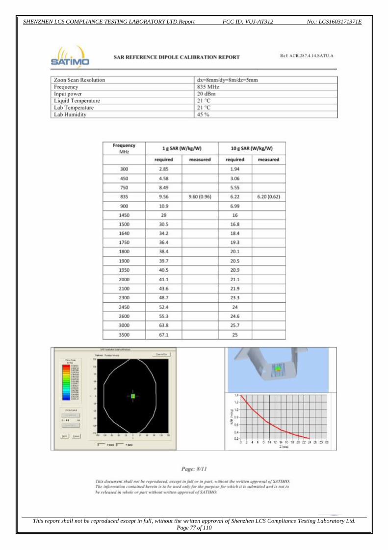
SHENZHEN LCS COMPLIANCE TESTING LABORATORY LTD.Report FCC ID: VUJ-AT312 No.: LCS1603171371E
This report shall not be reproduced except in full, without the written approval of Shenzhen LCS Compliance Testing Laboratory Ltd.
Page 77 of 110

SHENZHEN LCS COMPLIANCE TESTING LABORATORY LTD.Report FCC ID: VUJ-AT312 No.: LCS1603171371E
This report shall not be reproduced except in full, without the written approval of Shenzhen LCS Compliance Testing Laboratory Ltd.
Page 78 of 110

SHENZHEN LCS COMPLIANCE TESTING LABORATORY LTD.Report FCC ID: VUJ-AT312 No.: LCS1603171371E
This report shall not be reproduced except in full, without the written approval of Shenzhen LCS Compliance Testing Laboratory Ltd.
Page 79 of 110

SHENZHEN LCS COMPLIANCE TESTING LABORATORY LTD.Report FCC ID: VUJ-AT312 No.: LCS1603171371E
This report shall not be reproduced except in full, without the written approval of Shenzhen LCS Compliance Testing Laboratory Ltd.
Page 80 of 110