sapera lt 8 - 51camera51camera.com.cn/uploadfile/2016/1221/20161221033052567.pdf · p/n:...
TRANSCRIPT

Sapera LT™ 8.10 Getting Started Manual For GigE Vision Cameras
P/N: OC-SAPM-INTR0 www.teledynedalsa.com
sensors | cameras | frame grabbers | processors | software | vision solutions
NOTICE © 1998-2016 Teledyne DALSA, Inc. All rights reserved. This document may not be reproduced nor transmitted in any form or by any means, either electronic or mechanical, without the express written permission of TELEDYNE DALSA. Every effort is made to ensure the information in this manual is accurate and reliable. Use of the products described herein is understood to be at the user’s risk. TELEDYNE DALSA assumes no liability whatsoever for the use of the products detailed in this document and reserves the right to make changes in specifications at any time and without notice. Microsoft® is a registered trademark; Windows®, Windows® XP, Windows® Vista, Windows® 7, Windows® 8 are trademarks of Microsoft Corporation. All other trademarks or intellectual property mentioned herein belongs to their respective owners. Printed on January 6, 2016 Document Number: OC-SAPM-INTR0 Printed in Canada
About This Manual
This manual exists in Windows Help, and Adobe Acrobat® (PDF) formats (printed manuals are available as special orders). The Help and PDF formats make full use of hypertext cross-references. The Teledyne DALSA home page on the Internet, located at http://www.teledynedalsa.com/imaging, contains documents, software updates, demos, errata, utilities, and more. About Teledyne DALSA Teledyne DALSA is an international high performance semiconductor and electronics company that designs, develops, manufactures, and markets digital imaging products and solutions, in addition to providing wafer foundry services. Teledyne DALSA Digital Imaging offers the widest range of machine vision components in the world. From industry-leading image sensors through powerful and sophisticated cameras, frame grabbers, vision processors and software to easy-to-use vision appliances and custom vision modules.

Sapera LT Getting Started Manual Contents • 3
Contents SAPERA LT WITH GIGE VISION CAMERAS 5
Supported Industry Standard ................................................................... 5
INTRODUCTION TO SAPERA LT 6 SAPERA LT LICENSING...................................................................................... 6 THE SAPERA LT APIS ....................................................................................... 6 SAPERA TOOLS AND UTILITIES ............................................................................ 6 SAPERA LT MANUAL DESCRIPTIONS ...................................................................... 7 SUPPORTED OPERATING SYSTEMS ........................................................................ 8 SUPPORTED SAPERA LT DEVELOPMENT ENVIRONMENTS ............................................... 8 INSTALLATION TYPES ....................................................................................... 9
Upgrading Previous Versions of Sapera LT ............................................... 10 START MENU SHORTCUTS ................................................................................ 10 SAPERA LT ARCHITECTURE OVERVIEW ................................................................. 12
Application Architecture ........................................................................ 12 Library Architecture .............................................................................. 13 Configuration Files ................................................................................ 14
QUICK START GUIDE 15 USING SAPERA LT WITH A TELEDYNE DALSA GIGE VISION DEVICE .............................. 16
Sapera LT Classes For GigE Vision Device Applications .............................. 16 Connecting a Teledyne DALSA GigE Vision Camera ................................... 17
USING SAPERA LT WITH 3RD PARTY GIGE CAMERAS ................................................. 18 USING THE CAMEXPERT TOOL ........................................................................... 19
SAPERA LT UTILITIES 21 SAPERA MONITOR ......................................................................................... 21
The Sapera Monitor Window .................................................................. 21 Sapera Monitor Menu Commands ........................................................... 23 Using Sapera Monitor............................................................................ 25
SAPERA LOG VIEWER ..................................................................................... 26 NETWORK CONFIGURATION TOOL ....................................................................... 27
DEMOS AND EXAMPLES 28 DEMO SOURCE CODE ..................................................................................... 28 EXAMPLE SOURCE CODE .................................................................................. 28 DEMOS AND EXAMPLES FOR GIGE VISION DEVICES .................................................. 29 GENERIC SAPERA LT EXAMPLES ......................................................................... 31 ACQUIRING WITH GIGE-VISION CAMERA DEMO ...................................................... 32 USING THE GIGE SEQUENTIAL GRAB DEMO ........................................................... 34 USING THE GIGE METADATA DEMO ..................................................................... 36 USING THE GIGE-VISION FLAT FIELD DEMO .......................................................... 38
Flat Field Demo Main Window ................................................................ 38 Set up Dark and Bright Acquisitions with the Histogram Tool ..................... 39 Verify a Dark Acquisition ....................................................................... 40 Verify a Bright Acquisition ..................................................................... 41 Using Flat Field Correction ..................................................................... 42 Flat Field Calibration ............................................................................. 42 Setup Before Calibration ....................................................................... 43 Calibration Procedure ............................................................................ 44
SAPERA CAMERA COMPRESSION DEMO ................................................................. 45 Enable JPEG ........................................................................................ 45
4 • Contents Sapera LT Getting Started Manual
JPEG Decompression Statistics ............................................................... 45 Image Statistics ................................................................................... 45 Camera Information ............................................................................. 46 Message Area ...................................................................................... 46
CAMERA FIRMWARE UPDATE EXAMPLE .................................................................. 46
APPENDIX: FILE LOCATIONS 47
CONTACT INFORMATION 48 SALES INFORMATION ...................................................................................... 48 TECHNICAL SUPPORT ...................................................................................... 48
Sapera LT Getting Started Manual Sapera LT with GigE Vision Cameras • 5
Sapera LT with GigE Vision Cameras GigE Vision® cameras provide image acquisition using standard Gigabit Ethernet network adapters and Ethernet cables without the need for frame grabber hardware, and are suitable for a variety of applications. The GigE Vision standard provides a user friendly common interface to control camera functionality across platforms. GigE Vision cameras use an XML file, stored on the device, to describe the camera features, which are standardized. These features are then exposed through the Sapera API. All cameras that are GigE Vision compliant use the same feature names (established by the Standard Feature Naming Convention (SNFC)) to control the camera, though manufacturers can use camera specific features that are not part of this standard. The Sapera LT SDK includes the Network Imaging package which provides support for cameras that use the GigE Vision standard. The GigE Vision Module software provides all components required to control GigE Vision devices. GigE Vision cameras require a Gigabit Network Interface adapter. Refer to the camera documentation for more information.
Supported Industry Standard
GigE Vision cameras that are compliant with the GigE Vision 1.0 specification which defines the communication interface protocol used by any GigE Vision device. The device description and capabilities are contained in an XML file. For more information see: http://www.machinevisiononline.org/public/articles/index.cfm?cat=167

6 • Introduction to Sapera LT Sapera LT Getting Started Manual
Introduction to Sapera LT
Sapera™ LT is a software API for controlling image acquisition devices such as cameras. Sapera LT libraries support Teledyne DALSA cameras and frame grabbers as well as hundreds of 3rd party camera models across all common interfaces formats like GigE Vision®, Camera Link®, as well as emerging new image acquisition standards such as CLHS.
If your application requires image processing or GPU optimization, Sapera Essential, a full-featured image processing library, is available as a separate software package. For more information see www.teledynedalsa.com/imaging/products/software/.
The Sapera LT Getting Started Manual provides an introduction to the Sapera LT API and is designed to help programmer's with installation, and quickly perform hardware setup and validation.
Sapera LT Licensing Sapera LT is available free of charge, both SDK and runtime versions, when used with Teledyne DALSA frame grabber or camera products. However, if Sapera LT is used with 3rd party GigE cameras, a license must be purchased to activate the Sapera Network Imaging Package; refer to the section Using Sapera LT with 3rd Party GigE Cameras.
The Sapera LT APIs Sapera LT includes everything you need to acquire and display images, using one of its 3 application programming interfaces (API):
• Sapera LT++ classes (based on C++ language) • Sapera LT .NET classes (based on .NET languages) • Sapera LT Standard API (based on C language)
It is targeted at developers that have their own image processing libraries and want to interface those libraries to a Sapera LT compatible device. Sapera LT includes tools such as CamExpert to speed up application development.
Hardware independent classes allow one application to control different Teledyne DALSA devices through the same API. It also guarantees seamless migration to any future Teledyne DALSA hardware product supported by Sapera LT.
If you are using Sapera LT with a GigE Vision camera, the Sapera Network Imaging Package is also provided to communicate with and control devices using the GigE Vision protocol.
Sapera Tools and Utilities The Sapera LT SDK and runtime installations include the following a set of tools and utilities:
• CamExpert: acquisition and device configuration, including image display
• Sapera Monitor: real-time event viewing of applications.
• Sapera Log Viewer: error and other message log for applications and hardware
• Network Configuration Tool: network configuration
Sapera LT Getting Started Manual Introduction to Sapera LT • 7
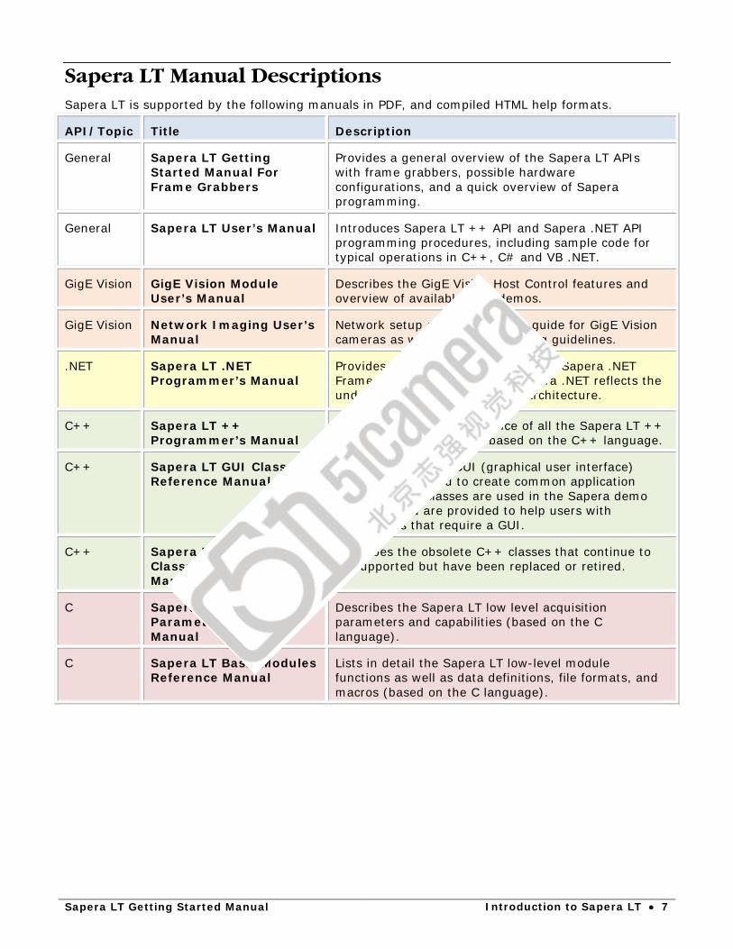
Sapera LT Manual Descriptions Sapera LT is supported by the following manuals in PDF, and compiled HTML help formats.
API/Topic Title Description
General Sapera LT Getting Started Manual For Frame Grabbers
Provides a general overview of the Sapera LT APIs with frame grabbers, possible hardware configurations, and a quick overview of Sapera programming.
General Sapera LT User’s Manual Introduces Sapera LT ++ API and Sapera .NET API programming procedures, including sample code for typical operations in C++, C# and VB .NET.
GigE Vision GigE Vision Module User’s Manual
Describes the GigE Vision Host Control features and overview of available GigE demos.
GigE Vision Network Imaging User’s Manual
Network setup and optimization guide for GigE Vision cameras as well as troubleshooting guidelines.
.NET Sapera LT .NET Programmer’s Manual
Provides a complete reference of the Sapera .NET Framework for Visual Studio. Sapera .NET reflects the underlying low-level Sapera LT architecture.
C++ Sapera LT ++ Programmer’s Manual
Provides a complete reference of all the Sapera LT ++ classes. Sapera LT ++ is based on the C++ language.
C++ Sapera LT GUI Classes Reference Manual
Describes the C++ GUI (graphical user interface) helper classes used to create common application dialogs. These classes are used in the Sapera demo programs and are provided to help users with applications that require a GUI.
C++ Sapera LT Legacy Classes Reference Manual
Describes the obsolete C++ classes that continue to be supported but have been replaced or retired.
C Sapera LT Acquisition Parameters Reference Manual
Describes the Sapera LT low level acquisition parameters and capabilities (based on the C language).
C Sapera LT Basic Modules Reference Manual
Lists in detail the Sapera LT low-level module functions as well as data definitions, file formats, and macros (based on the C language).

8 • Introduction to Sapera LT Sapera LT Getting Started Manual
Supported Operating Systems • Windows XP® (32-bit and 64-bit) • Windows 7® (32-bit and 64-bit) • Windows 8® (32-bit and 64-bit) • Windows 8.1® (32-bit and 64-bit) • Windows 10® (32-bit and 64-bit) (Note: Windows NT 4.0, Windows 2000 and Windows Vista are no longer supported.)
Supported Sapera LT Development Environments • PCI-bus IBM PC or compatible with Pentium class or later processor • C/C++ and .NET language compilers, for both 32-bit and 64-bit development:
• Microsoft Visual Studio 2005 (with Service Pack 1) • Microsoft Visual Studio 2008 (with Service Pack 1) • Microsoft Visual Studio 2010 • Microsoft Visual Studio 2012 • Microsoft Visual Studio 2013
For 32-bit development:
• Borland C++Builder XE(versions XE1 to XE5)
If you are using Visual Studio 2005 or 2008 to develop Sapera LT applications, then you should have the latest Service Pack plus all security patches installed. You can check if these are installed through the Help->About menu item in Visual Studio.
Sapera LT Getting Started Manual Introduction to Sapera LT • 9
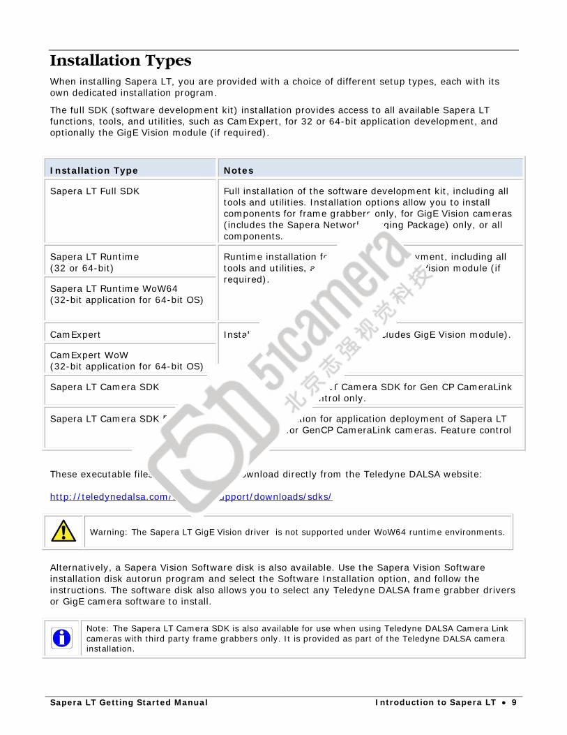
Installation Types When installing Sapera LT, you are provided with a choice of different setup types, each with its own dedicated installation program.
The full SDK (software development kit) installation provides access to all available Sapera LT functions, tools, and utilities, such as CamExpert, for 32 or 64-bit application development, and optionally the GigE Vision module (if required).
Installation Type Notes
Sapera LT Full SDK Full installation of the software development kit, including all tools and utilities. Installation options allow you to install components for frame grabbers only, for GigE Vision cameras (includes the Sapera Network Imaging Package) only, or all components.
Sapera LT Runtime (32 or 64-bit)
Runtime installation for application deployment, including all tools and utilities, and optionally the GigE Vision module (if required).
Sapera LT Runtime WoW64 (32-bit application for 64-bit OS)
CamExpert Installation of CamExpert only (includes GigE Vision module).
CamExpert WoW (32-bit application for 64-bit OS)
Sapera LT Camera SDK Installation of Sapera LT Camera SDK for Gen CP CameraLink cameras. Feature control only.
Sapera LT Camera SDK Runtime Runtime installation for application deployment of Sapera LT Camera SDK for GenCP CameraLink cameras. Feature control only.
These executable files are available for download directly from the Teledyne DALSA website: http://teledynedalsa.com/imaging/support/downloads/sdks/
Warning: The Sapera LT GigE Vision driver is not supported under WoW64 runtime environments.
Alternatively, a Sapera Vision Software disk is also available. Use the Sapera Vision Software installation disk autorun program and select the Software Installation option, and follow the instructions. The software disk also allows you to select any Teledyne DALSA frame grabber drivers or GigE camera software to install.
Note: The Sapera LT Camera SDK is also available for use when using Teledyne DALSA Camera Link cameras with third party frame grabbers only. It is provided as part of the Teledyne DALSA camera installation.

10 • Introduction to Sapera LT Sapera LT Getting Started Manual
Upgrading Previous Versions of Sapera LT
Sapera LT 7.30 and Higher
When upgrading from Sapera LT version 7.30 or higher, uninstalling is not required; proceed directly to installation of Sapera LT 8.10
Sapera LT 7.20 and Lower
Before installing Sapera LT 8.10, uninstall Sapera LT from the Windows Control Panel > Programs and Features.
Start Menu Shortcuts For Windows 7, Start Menu shortcuts for Sapera LT are available under All Programs > Teledyne DALSA > Sapera LT and >Sapera Network Imaging Package. The following screenshots display the menus for the full Sapera LT SDK.

Sapera LT Getting Started Manual Introduction to Sapera LT • 11
For Windows 8, shortcuts are presented as tiles on the desktop through the Apps menu.
See Appendix: File Locations for a complete description of directory contents.

12 • Introduction to Sapera LT Sapera LT Getting Started Manual
Sapera LT Architecture Overview The following section describes application architecture, related terms, and illustrates Sapera LT’s library architecture.
Application Architecture
Whichever API is used (Sapera LT ++, Sapera LT .NET, or Standard C), the Sapera LT modular architecture allows applications to be distributed on different Sapera LT servers. Each server can run either on the host computer or on a Teledyne DALSA device. Sapera LT calls are routed to different servers via the Sapera LT messaging layer in a fashion completely independent of the underlying hardware.
What is a server?
A Sapera Server is an abstract representation of a physical device like a frame grabber, a camera, or a desktop PC. In general, a Teledyne DALSA board is a server. Some processing boards, however, may contain several servers; this is true when using multi-processor boards.
A server allows Sapera applications to interact with the server’s resources.
Sapera LT Getting Started Manual Introduction to Sapera LT • 13
Library Architecture
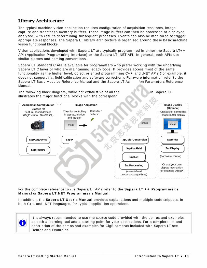
The typical machine vision application requires configuration of acquisition resources, image capture and transfer to memory buffers. These image buffers can then be processed or displayed, analyzed, with results determining subsequent processes. Events can also be monitored to trigger appropriate responses. The Sapera LT library architecture is organized around these basic machine vision functional blocks.
Vision applications developed with Sapera LT are typically programmed in either the Sapera LT++ API (Application Programming Interface) or the Sapera LT .NET API. In general, both APIs use similar classes and naming conventions.
Sapera LT Standard C API is available for programmers who prefer working with the underlying Sapera LT C layer or who are maintaining legacy code. It provides access most of the same functionality as the higher level, object oriented programming C++ and .NET APIs (for example, it does not support flat field calibration and software correction). For more information refer to the Sapera LT Basic Modules Reference Manual and the Sapera LT Acquisition Parameters Reference Manual.
The following block diagram, while not exhaustive of all the classes available in Sapera LT, illustrates the major functional blocks with the corresponding classes.
Classes for feature-based devices
(GigE Vision | GenCP CL)
(hardware control)
Image Display(Optional)
SapDisplay
Or use your own display mechanism
(for example DirectX)
Classes for controlling image buffer display
SapView
ImageImage
SapFlatField
SapColorConversion
SapLut
SapProcessing
(user-defined processing algorithms)
Image
Classes for image processing
Image Acquistion
Image
Class for image buffer resources
Class for controlling image acquisition
and transfer
SapTransfer SapBufferSapAcqDevice
Acquisition Configuration
SapFeature
Software Processing(Optional)
For the complete reference to the Sapera LT APIs refer to the Sapera LT ++ Programmer’s Manual or Sapera LT.NET Programmer’s Manual.
In addition, the Sapera LT User’s Manual provides explanations and multiple code snippets, in both C++ and .NET languages, for typical application operations.
It is always recommended to use the source code provided with the demos and examples as both a learning tool and a starting point for your applications. For a complete list and description of the demos and examples for GigE cameras included with Sapera LT see Demos and Examples.

14 • Introduction to Sapera LT Sapera LT Getting Started Manual
Configuration Files
Most GigE cameras support saving a user-defined set of parameter settings that can be loaded instead of the factory defaults on power-up.
If the camera supports file access, the feature parameter settings can be downloaded from the camera and saved to a file. This file can then be uploaded to a camera to use these feature settings and saved as a user set. This can be useful if you want to use the same settings for multiple cameras.
If the camera does not support file access Sapera LT applications can load an acquisition configuration file before acquiring images from a camera. The camera configuration file has the extension .ccf.
Use CamExpert to generate a .ccf file for cameras with parameters as required by your imaging project.
The SapAcqDevice constructor, for GeniCam-compliant cameras, have prototypes that use .ccf files. For cameras, if no .ccf file is available, the camera default parameters are used.

Sapera LT Getting Started Manual Quick Start Guide • 15
Quick Start Guide For Teledyne DALSA GigE Vision cameras, during installation, choose either the option to install Sapera LT for GigE Vision cameras and the Sapera Network Imaging Package or All acquisition components.
Note that if you try to install Sapera LT from a network location you will not be able to install the Sapera Network Imaging Package; copy the installation executable locally.
Currently, Sapera LT supports GenICam GenCP CL and GigE Vision standards (including all mandatory feature requirements).

16 • Quick Start Guide Sapera LT Getting Started Manual
Using Sapera LT with a Teledyne DALSA GigE Vision Device
Sapera LT Classes For GigE Vision Device Applications The following diagram represents a typical application flow showing the Sapera LT object types associated with each component or stage.
GigE Vision cameras require a Gigabit network connection on the host computer which is not used on a corporate network; refer to the Sapera Network Imaging Package documentation for installation requirements.
Sapera LT Getting Started Manual Quick Start Guide • 17
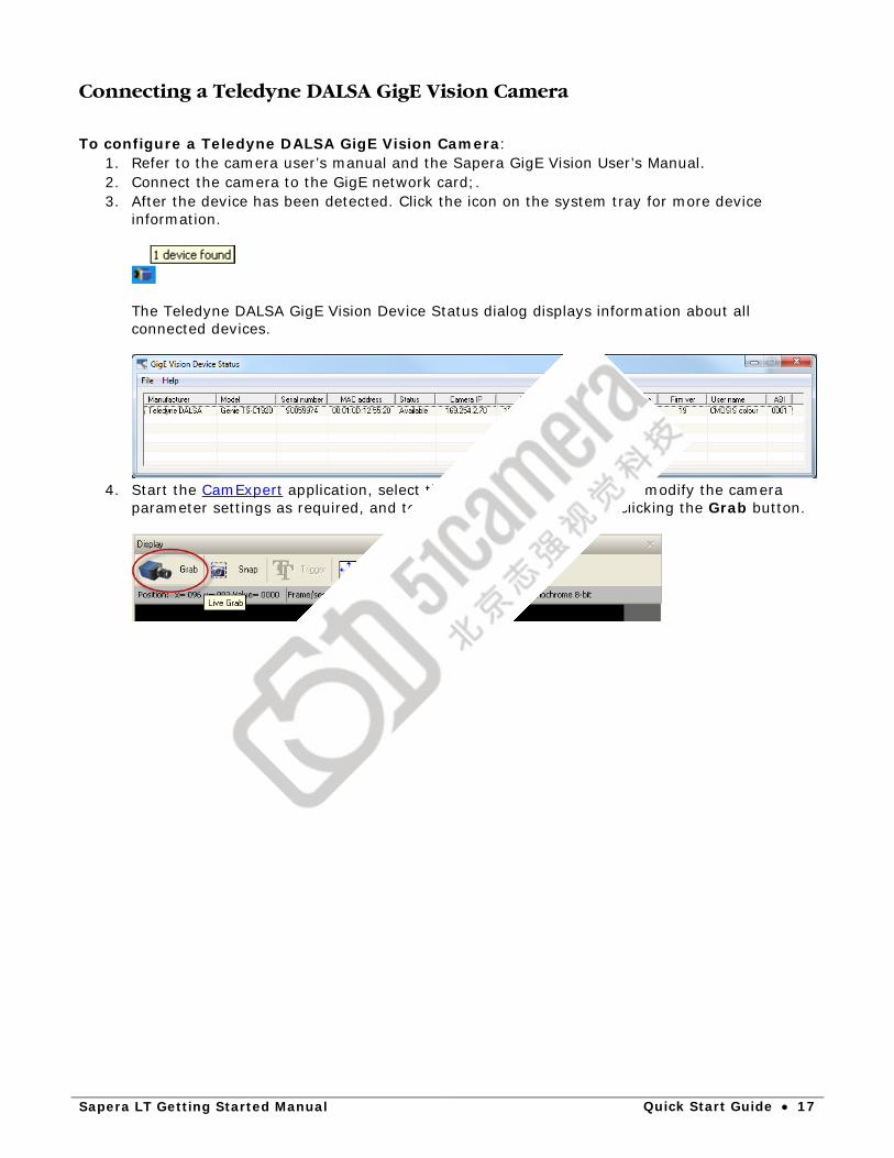
Connecting a Teledyne DALSA GigE Vision Camera
To configure a Teledyne DALSA GigE Vision Camera:
1. Refer to the camera user’s manual and the Sapera GigE Vision User’s Manual. 2. Connect the camera to the GigE network card;. 3. After the device has been detected. Click the icon on the system tray for more device
information.
The Teledyne DALSA GigE Vision Device Status dialog displays information about all connected devices.
4. Start the CamExpert application, select the camera to configure, and modify the camera
parameter settings as required, and test the image acquisition by clicking the Grab button.
18 • Quick Start Guide Sapera LT Getting Started Manual
Using Sapera LT with 3rd Party GigE Cameras If you are using the Sapera LT SDK with 3rd party GigE cameras only, a valid Sapera Processing license is required to activate the Teledyne DALSA GigE Vision Module. The Sapera License Manager Tool must be installed with Sapera LT to activate this license.
Note: When using a Sapera LT application with 3rd party GigE Vision cameras without Sapera Processing or a Teledyne DALSA GigE Vision connected on the same system, a license is required to unlock the Sapera LT GigE Vision Module. For more information, contact your Teledyne DALSA sales representative.
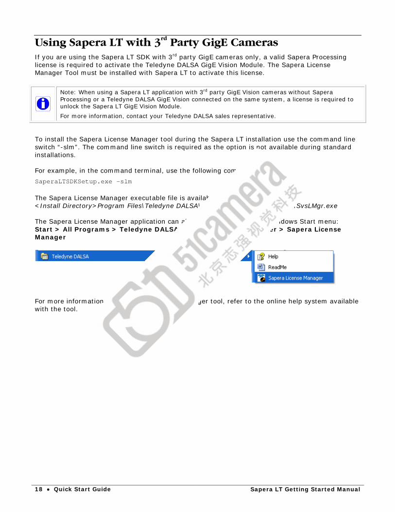
To install the Sapera License Manager tool during the Sapera LT installation use the command line switch “-slm”. The command line switch is required as the option is not available during standard installations. For example, in the command terminal, use the following command: SaperaLTSDKSetup.exe –slm The Sapera License Manager executable file is available in the following directory: <Install Directory>Program Files\Teledyne DALSA\Sapera License Manager\Bin\SvsLMgr.exe The Sapera License Manager application can also be launched from the Windows Start menu: Start > All Programs > Teledyne DALSA > Sapera License Manager > Sapera License Manager
For more information on the Sapera License Manager tool, refer to the online help system available with the tool.
Sapera LT Getting Started Manual Quick Start Guide • 19
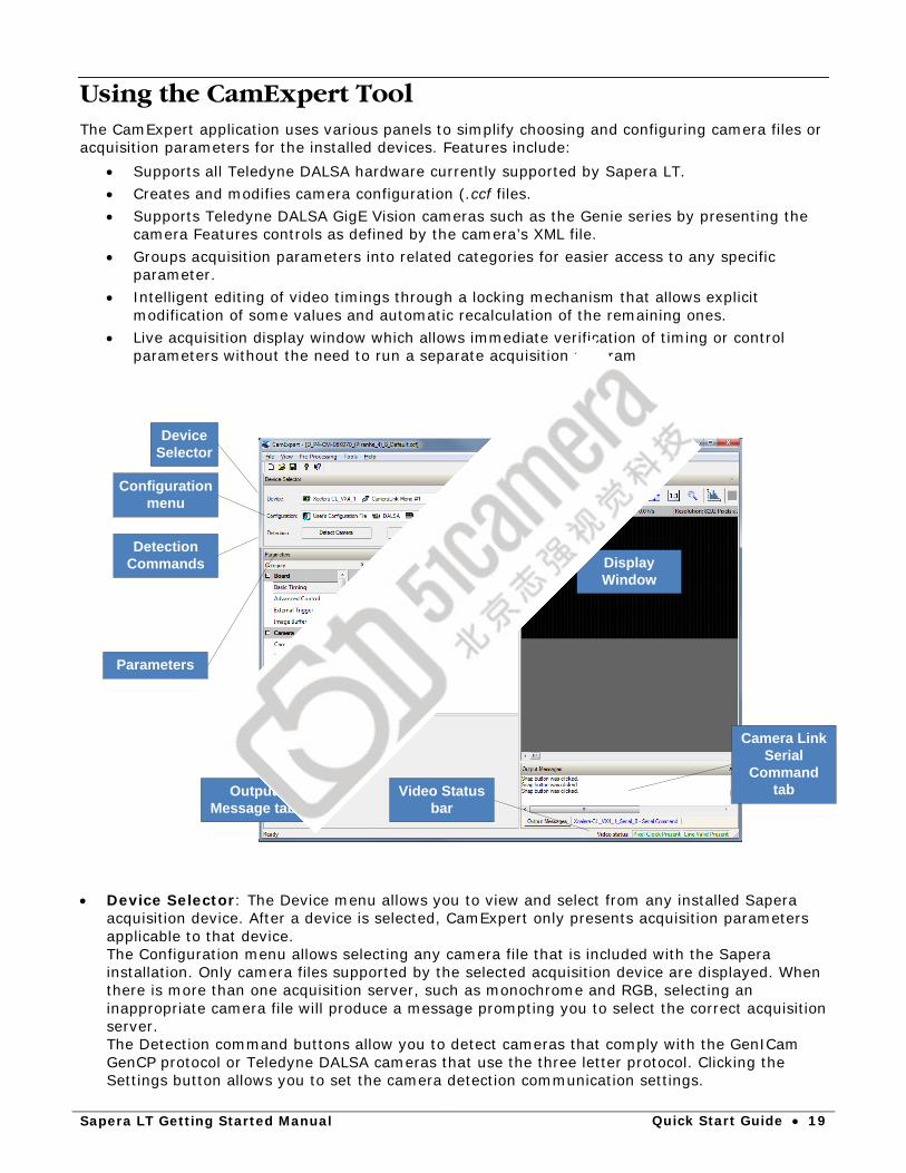
Using the CamExpert Tool The CamExpert application uses various panels to simplify choosing and configuring camera files or acquisition parameters for the installed devices. Features include:
• Supports all Teledyne DALSA hardware currently supported by Sapera LT. • Creates and modifies camera configuration (.ccf files. • Supports Teledyne DALSA GigE Vision cameras such as the Genie series by presenting the
camera Features controls as defined by the camera’s XML file. • Groups acquisition parameters into related categories for easier access to any specific
parameter. • Intelligent editing of video timings through a locking mechanism that allows explicit
modification of some values and automatic recalculation of the remaining ones. • Live acquisition display window which allows immediate verification of timing or control
parameters without the need to run a separate acquisition program
Device Selector
Configuration menu
Detection Commands
Parameters
Output Message tab
Display Window
Camera Link Serial
Command tabVideo Status
bar
• Device Selector: The Device menu allows you to view and select from any installed Sapera
acquisition device. After a device is selected, CamExpert only presents acquisition parameters applicable to that device. The Configuration menu allows selecting any camera file that is included with the Sapera installation. Only camera files supported by the selected acquisition device are displayed. When there is more than one acquisition server, such as monochrome and RGB, selecting an inappropriate camera file will produce a message prompting you to select the correct acquisition server. The Detection command buttons allow you to detect cameras that comply with the GenICam GenCP protocol or Teledyne DALSA cameras that use the three letter protocol. Clicking the Settings button allows you to set the camera detection communication settings.
20 • Quick Start Guide Sapera LT Getting Started Manual
• Parameters panel: Allows viewing or changing all acquisition parameters supported by the acquisition device. CamExpert displays parameters only if those parameters are supported by the installed device. This avoids confusion by eliminating parameter choices when they do not apply to the hardware in use.
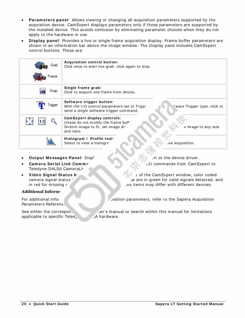
• Display panel: Provides a live or single frame acquisition display. Frame buffer parameters are shown in an information bar above the image window. The Display pane includes CamExpert control buttons. These are:
Acquisition control button: Click once to start live grab, click again to stop.
Single frame grab: Click to acquire one frame from device.
Software trigger button: With the I/O control parameters set to Trigger Enabled / Software Trigger type, click to send a single software trigger command.
CamExpert display controls: (these do not modify the frame buffer data) Stretch image to fit, set image display to original size, or zoom the image to any size and ratio.
Histogram / Profile tool: Select to view a histogram or line/column profile during live acquisition.
• Output Messages Panel: Displays messages from CamExpert or the device driver. • Camera Serial Link Command tab: Use this to send ASCII commands from CamExpert to
Teledyne DALSA CameraLink cameras. • Video Signal Status bar: Located on the lower right of the CamExpert window, color coded
camera signal status information is displayed. These are in green for valid signals detected, and in red for missing or incorrect signals. Video status items may differ with different devices.
Additional Information
For additional information about Sapera acquisition parameters, refer to the Sapera Acquisition Parameters Reference Manual.
See either the corresponding device user’s manual or search within this manual for limitations applicable to specific Teledyne DALSA hardware.
Sapera LT Getting Started Manual Quick Start Guide • 21
Sapera LT Utilities
Sapera LT includes the following utilities that can be used to monitor Sapera LT hardware and software events, error messages, as well as network configuration and diagnostics: Sapera Monitor Monitors user selected events generated by a Sapera LT
application. Sapera Log Viewer Displays error and other messages generated by Sapera LT
applications and Teledyne DALSA hardware. Network Configuration Tool The Network Configuration tool provides information and
parameter adjustments for network adapters installed in the system and any connected GigE Vision camera without use of any Windows Control Panel application.
Sapera Monitor As part of the Trigger-to-Image-Reliability (T2IR) framework, the Sapera Monitor tool allows users to view the acquisition and transfer events generated by an acquisition device in real-time. This is very useful since one can use the Sapera Monitor tool to debug application s and identify problems without having to code event handlers.
The key advantage to Sapera Monitor is that it can run concurrently with CamExpert or your own application. This can be useful for debugging applications and identifying problems without having to code event handlers.
To launch the Sapera Monitor use the Start•All Programs•Teledyne DALSA•Sapera LT•Tools•Sapera Monitor menu shortcut.
Note: older driver versions of Teledyne DALSA devices may not support Sapera Monitor. Check the Teledyne DALSA website for updated drivers for your device that support Sapera Monitor. In addition, when using Teledyne DALSA Genie devices, you must start a Sapera application, such as CamExpert, that uses the device you want to monitor, before launching Sapera Monitor.
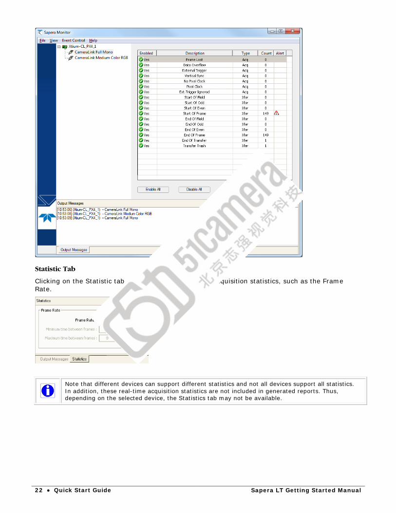
The Sapera Monitor Window
The Sapera Monitor Window is divided into three panes: • Device directory tree: displays the available acquisition devices to monitor • Event table: displays the available events to monitor for the selected device • Output Messages pane: displays the messages generated by the selected monitored events.
22 • Quick Start Guide Sapera LT Getting Started Manual
Statistic Tab
Clicking on the Statistic tab displays various real-time acquisition statistics, such as the Frame Rate.
Note that different devices can support different statistics and not all devices support all statistics. In addition, these real-time acquisition statistics are not included in generated reports. Thus, depending on the selected device, the Statistics tab may not be available.

Sapera LT Getting Started Manual Quick Start Guide • 23
Sapera Monitor Menu Commands
The Sapera Monitor menu provides access to File, View, and Event Control commands.
File Menu Commands
The File•Generate Report command generates a text file report that includes all event settings and messages included in the current Output Messages pane.
The File•Clear Log Information command clears the current Output Messages pane.
View Menu Commands
The View•Always on Top command displays the Sapera Monitor on top of any other windows that may be visible on the desktop.
The View•Select Events command opens the Sapera Monitor Events Display Settings dialog which allows you to specify the events to display in the Event table.
24 • Quick Start Guide Sapera LT Getting Started Manual
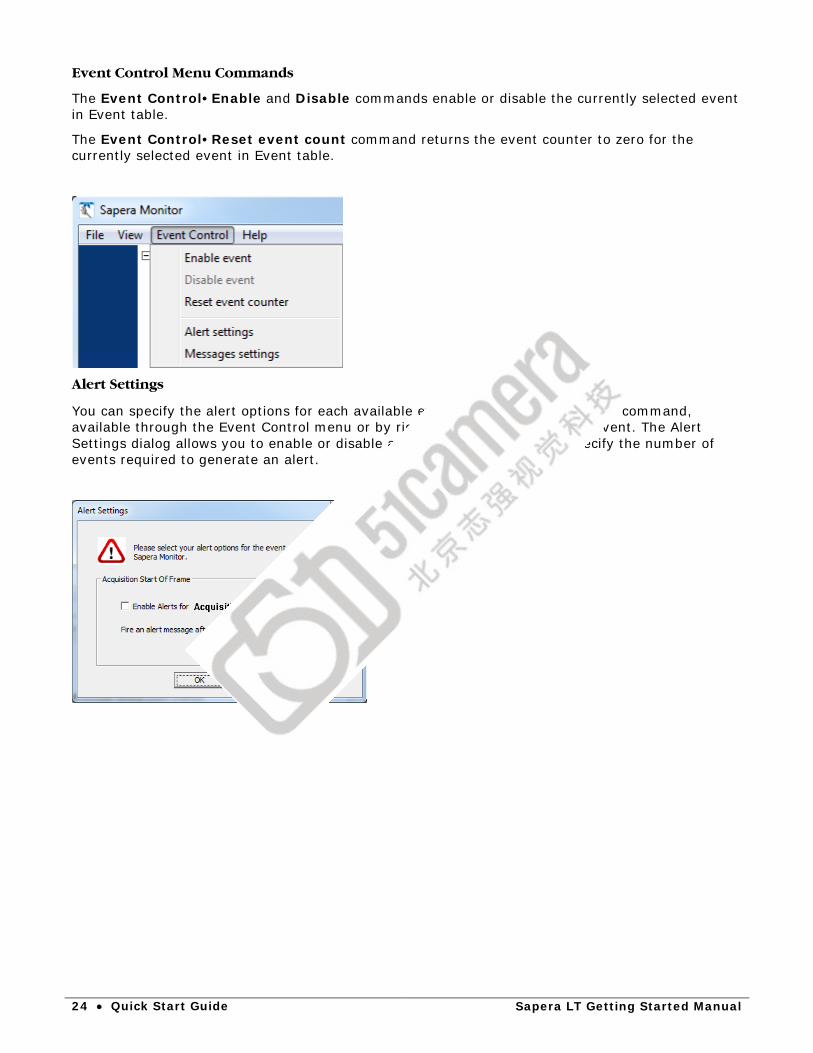
Event Control Menu Commands
The Event Control•Enable and Disable commands enable or disable the currently selected event in Event table.
The Event Control•Reset event count command returns the event counter to zero for the currently selected event in Event table.
Alert Settings
You can specify the alert options for each available event using the Alert Settings command, available through the Event Control menu or by right-clicking on the selected event. The Alert Settings dialog allows you to enable or disable alerts for the event and to specify the number of events required to generate an alert.

Sapera LT Getting Started Manual Quick Start Guide • 25
When an alert is generated , the Alert icon is displayed in the Alert column of the event.
An alert message, in red, also appears in the Output Messages Settings pane.
Message Settings
You can specify the events to enable message logging and the number of events required to generate a log message using the Message Settings command, available through the Event Control menu or by right-clicking on the selected event.. The log messages appear in the Output Message pane.
Using Sapera Monitor
To use the Sapera Monitor tool to monitor a device: • Run a Sapera application, such as CamExpert, that uses the device. • Launch the Sapera Monitor application • In the Sapera Monitor Device directory tree, select the device. • In the Sapera Monitor Event table, select the events to monitor. Double-clicking on the row
containing the event toggles the Enabled status between and . Right-clicking on the event opens a context menu which provides easy access to commands to reset the event counter, and modify the event Alert settings or Message settings.

26 • Quick Start Guide Sapera LT Getting Started Manual
These commands are also available through the Event Control Menu. Alternatively, you can use the Enable All and Disable All buttons to quickly clear or select events.
Sapera Log Viewer The Sapera Log Viewer utility program included with Sapera LT provides an easy way to view error and other types of messages generated by Sapera LT applications and Teledyne DALSA hardware, such as cameras and frame grabbers. Typically, the Sapera Log Viewer application is used by technical support to troubleshoot software and hardware problems.
During development it is recommended to start the Sapera Log Viewer before your application and then let it run so it can be referred to any time a detailed error description is required. However, errors are also stored by a low-level service (running in the background), even if the utility is not running. Therefore it is possible to run it only when a problem occurs with your application.
Refer to the utility’s online help for more information on using the Sapera Log Viewer.
Sapera LT Getting Started Manual Quick Start Guide • 27
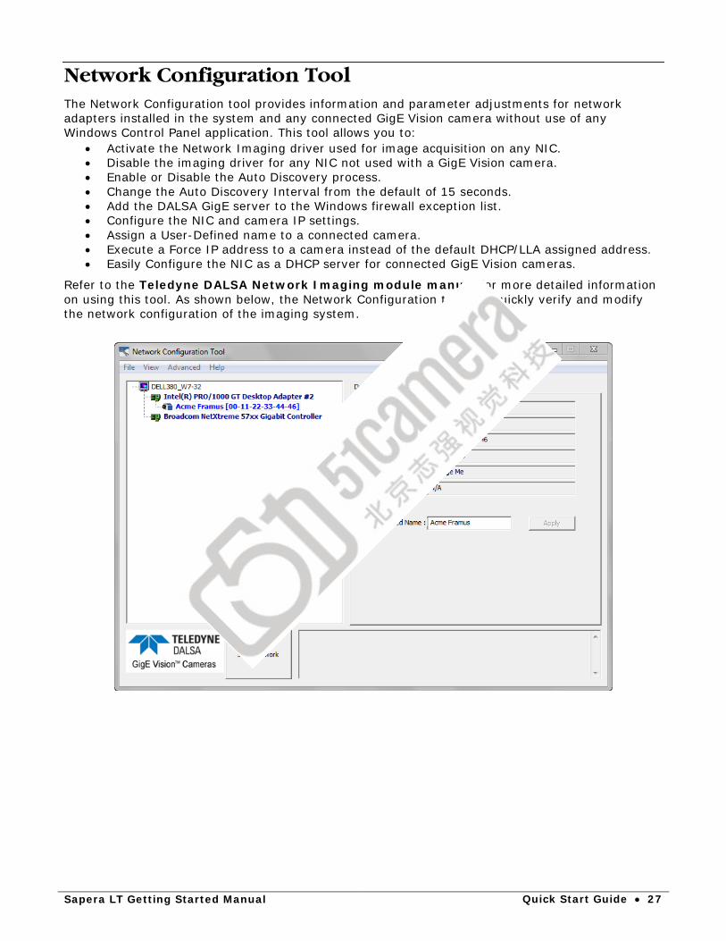
Network Configuration Tool The Network Configuration tool provides information and parameter adjustments for network adapters installed in the system and any connected GigE Vision camera without use of any Windows Control Panel application. This tool allows you to:
• Activate the Network Imaging driver used for image acquisition on any NIC. • Disable the imaging driver for any NIC not used with a GigE Vision camera. • Enable or Disable the Auto Discovery process. • Change the Auto Discovery Interval from the default of 15 seconds. • Add the DALSA GigE server to the Windows firewall exception list. • Configure the NIC and camera IP settings. • Assign a User-Defined name to a connected camera. • Execute a Force IP address to a camera instead of the default DHCP/LLA assigned address. • Easily Configure the NIC as a DHCP server for connected GigE Vision cameras.
Refer to the Teledyne DALSA Network Imaging module manual for more detailed information on using this tool. As shown below, the Network Configuration tool can quickly verify and modify the network configuration of the imaging system.
28 • Demos and Examples Sapera LT Getting Started Manual
Demos and Examples
Several generic demos and examples are available for both Sapera ++ and Sapera .NET. Complete source code is provided for projects in Microsoft Visual Studio 2005 to 2013.
Source code for Sapera LT ++ based demos and examples can now be compiled as Unicode instead of ANSI. Project files provided by Sapera for Visual Studio 2012 now support both character sets. However, project files for earlier versions of Visual Studio still support ANSI only. Project files for Visual Studio 2013 support Unicode only.
If your application requires a user interface, Sapera LT includes the GUI classes used by many of the demos to create commonly used dialog boxes. The GUI classes include a set of Microsoft® Foundation Classes (MFC) based dialog boxes designed to implement some of the most commonly used tasks for Sapera LT applications, such as loading an acquisition configuration file. They, however, do not constitute an official API. Rather, they are provided 'as is' with source code so that you may modify them at your discretion. For more information on these classes refer to the Sapera LT GUI Class Reference manual.
Certain device driver installations provide other demos and examples that demonstrate the specific usages and capabilities of the device. Refer to a specific device user’s manual for further details.
Demo Source Code Several demo programs are available with Sapera. They are more complete applications than the supplied examples. There are demos that cover Sapera LT ++ and Sapera .NET.
The demos main purpose is to provide the user with a starting application that can be modified in order to become the user’s end application.
The Sapera LT ++ and Sapera LT .NET demo source code for the supported compilers are found in the following directory:
• Sapera\Demos
Projects are also provided to allow you to recompile all the demos in a batch, together with the Sapera LT ++ GUI Classes.
Example Source Code Several example programs are available within Sapera. They are essentially basic applications demonstrating simple tasks like grabbing an image and loading an image file from the disk.
The main purpose of the examples is to provide the user with code samples that can be easily extracted and integrated into an application. Examples cover both Sapera LT ++ and Sapera .NET.
The Sapera LT ++ and .NET example source code for the supported compilers are found in the following directory:
• Sapera\Examples Projects are also provided to allow you to recompile all the examples in a batch.
Note: (32-bit only) You can open the Borland C++ Builder XE1 project file supplied with Sapera LT (Sapera\Examples\Classes\SapExamples.groupproj) from more recent versions of C++ Builder XE, and it will automatically be converted to the appropriate format.
Sapera LT Getting Started Manual Demos and Examples • 29
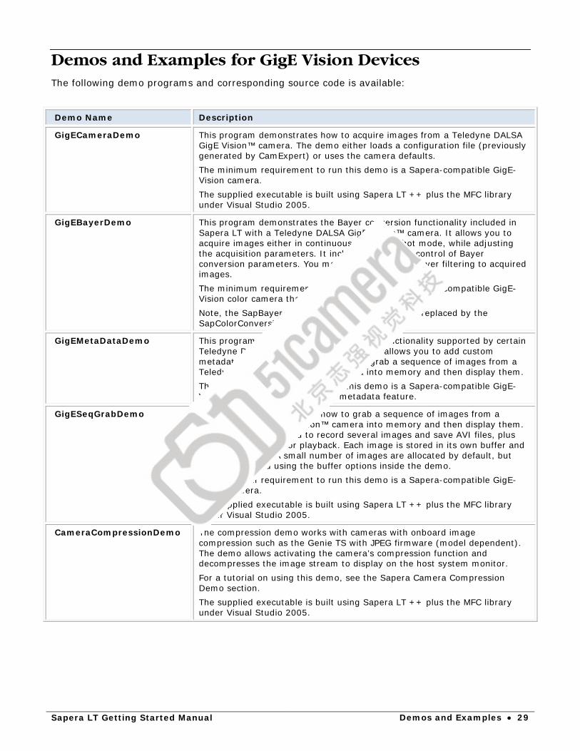
Demos and Examples for GigE Vision Devices The following demo programs and corresponding source code is available:
Demo Name Description
GigECameraDemo This program demonstrates how to acquire images from a Teledyne DALSA GigE Vision™ camera. The demo either loads a configuration file (previously generated by CamExpert) or uses the camera defaults. The minimum requirement to run this demo is a Sapera-compatible GigE-Vision camera. The supplied executable is built using Sapera LT ++ plus the MFC library under Visual Studio 2005.
GigEBayerDemo This program demonstrates the Bayer conversion functionality included in Sapera LT with a Teledyne DALSA GigE Vision™ camera. It allows you to acquire images either in continuous or in one-shot mode, while adjusting the acquisition parameters. It includes interactive control of Bayer conversion parameters. You may optionally apply Bayer filtering to acquired images. The minimum requirement to run this demo is a Sapera-compatible GigE-Vision color camera that output Bayer format. Note, the SapBayer class has been deprecated and replaced by the SapColorConversion class.
GigEMetaDataDemo This program demonstrates the metadata functionality supported by certain Teledyne DALSA GigE Vision™ cameras. It allows you to add custom metadata to images. In addition, it can grab a sequence of images from a Teledyne DALSA GigE Vision™ camera into memory and then display them. The minimum requirement to run this demo is a Sapera-compatible GigE-Vision camera that supports the metadata feature.
GigESeqGrabDemo This program demonstrates how to grab a sequence of images from a Teledyne DALSA GigE Vision™ camera into memory and then display them. The program allows you to record several images and save AVI files, plus load those AVI files for playback. Each image is stored in its own buffer and can be reviewed. A small number of images are allocated by default, but can be increased using the buffer options inside the demo. The minimum requirement to run this demo is a Sapera-compatible GigE-Vision camera. The supplied executable is built using Sapera LT ++ plus the MFC library under Visual Studio 2005.
CameraCompressionDemo The compression demo works with cameras with onboard image compression such as the Genie TS with JPEG firmware (model dependent). The demo allows activating the camera’s compression function and decompresses the image stream to display on the host system monitor. For a tutorial on using this demo, see the Sapera Camera Compression Demo section. The supplied executable is built using Sapera LT ++ plus the MFC library under Visual Studio 2005.

30 • Demos and Examples Sapera LT Getting Started Manual
GigEFlatFieldDemo This program demonstrates how to use the flat field correction function included in Sapera LT ++ with a Teledyne DALSA GigE Vision™ camera. Flat Field Correction (FFC) includes Fixed Pattern Noise (FPN), Pixel Replacement, Photo Response Non Uniformity (PRNU), and Shading Correction. The demo allows you to acquire images either in continuous or in one-shot mode, while adjusting the acquisition parameters. It includes interactive calibration of flat field gain and offset settings. You may optionally apply flat field correction to previously acquired images. The minimum requirement to run this demo is a Sapera-compatible GigE-Vision camera. The supplied executable is built using Sapera LT ++ plus the MFC library under Visual Studio 2005.
The following compiled console examples and source code is available:
Example Name Description
CameraEvents This example shows how to list all the available events with SapAcqDevice. Using the registering and unregistering callback mechanism, it shows also how to track when a specific event occurs.
CameraFeatures This example shows how to enumerate available features on a camera for example, Genie or GigE). It also shows how to retrieve feature specific information (for example, access mode), and how to change feature values.
CameraFiles This example shows how to upload/download files for GigE or GenCP cameras that support file access such as firmware upload and LUTs.
GigEFirmwareUpdate This example shows how to update firmware for GigE cameras that support file access, allowing automatic firmware updates at the application level.
FindCamera This example shows how to list all detected cameras (for example, Genie or GigE) when more than one camera is present, listing them by user name, serial number, model name or server name. By uncommenting a part of code, you will be able to change the user defined name of the camera.
GrabCPP Grab Console. This example shows how to grab an image from a selected camera into a Sapera buffer and then display it. The buffer is created according to the camera settings. Any Sapera compatible frame grabber or GigE camera can be used. This example is named Grab in .NET.
GigEAutoWhiteBalance This example shows how to apply the auto white balance algorithm with SapAcqDevice on a Genie or GigE color camera. This program modifies the buffer format if necessary and restores the original one. It shows how to grab an image from a selected camera into a Sapera buffer and then display it (before and after the calibration.) Original Genie Color cameras only.
GigECameraLut This example shows how to grab images from a selected Genie or GigE camera into a buffer in the host computer's memory. This program also shows how to enable, save and load a lookup-table (LUT) into the hardware processing engine and display the image with the Lut selected. Original Genie (color or monochrome) cameras.

Sapera LT Getting Started Manual Demos and Examples • 31
Generic Sapera LT Examples The following compiled console examples and source code is available:
Example Name Description
ColorSplit Shows how to split and merge color images into single monochrome components. An RGB image is loaded, split into three monochrome components, then a simple processing is applied to the three components before they are merged back to RGB as output.
FileLoadCPP This example shows how to load an image file from the disk into a Sapera buffer and then display it. The buffer is created according to the image file properties. One of several images (monochrome, RGB, or YUV) can be selected for loading. This example is named FileLoad in .NET.
FileLoadMFC Same as the FileLoadCPP Example, but additionally uses the Sapera LT ++ GUI classes allowing file browser usage. This example is not available in .NET.
32 • Demos and Examples Sapera LT Getting Started Manual
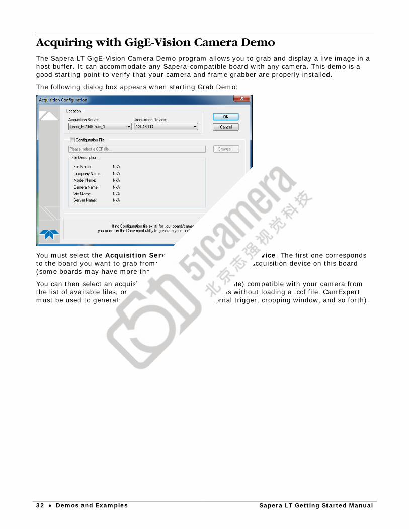
Acquiring with GigE-Vision Camera Demo The Sapera LT GigE-Vision Camera Demo program allows you to grab and display a live image in a host buffer. It can accommodate any Sapera-compatible board with any camera. This demo is a good starting point to verify that your camera and frame grabber are properly installed.
The following dialog box appears when starting Grab Demo:
You must select the Acquisition Server and the Acquisition Device. The first one corresponds to the board you want to grab from; the second represents the acquisition device on this board (some boards may have more than one).
You can then select an acquisition configuration file (CCF File) compatible with your camera from the list of available files, or use the camera default values without loading a .ccf file. CamExpert must be used to generate CCF files (for example, external trigger, cropping window, and so forth).

Sapera LT Getting Started Manual Demos and Examples • 33
Click OK to start the demo.
By using GigE-Vision Camera Demo you can now: • Control the acquisition using the Snap, Grab, and Freeze buttons. • Load/save images from/to disks using the Load and Save buttons. • Reload the CCF file using the Load Config button (this overwrites all the parameters
modified in step 3). • The Buffer button allows you to change the number of buffers used for internal cycling and
the type of buffer used (contiguous, scatter-gather, off-screen, or overlay). • The View button allows you to adjust the scaling and the select the bit range to display
when grabbing images with formats greater than 8-bits.
34 • Demos and Examples Sapera LT Getting Started Manual
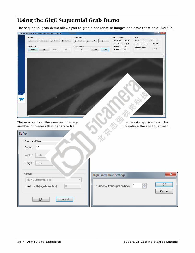
Using the GigE Sequential Grab Demo The sequential grab demo allows you to grab a sequence of images and save them as a .AVI file.
The user can set the number of images in the sequence. For high frame rate applications, the number of frames that generate transfer events can be increased to reduce the CPU overhead.

Sapera LT Getting Started Manual Demos and Examples • 35
The demo also displays the timestamps generated by the camera and saved in the image buffer. These timestamps can be analyzed to ensure that no images are lost. In addition, clicking the camera timestamp Reset button provides an easy way to calculate the round trip required for a function to be sent to the camera and the response received, providing a means to evaluate the network speed.

36 • Demos and Examples Sapera LT Getting Started Manual
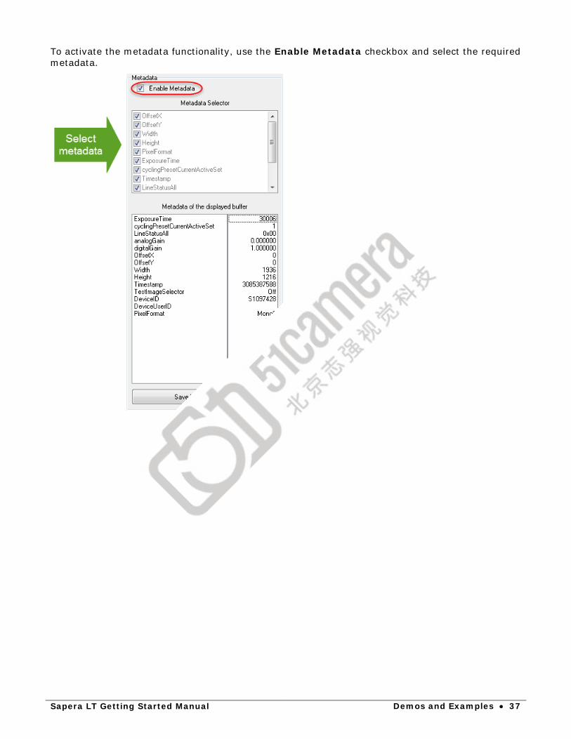
Using the GigE Metadata Demo For GigE cameras that support metadata, the GigE Metadata Demo allows you to select the metadata to generate for images and save this metadata to file. It also includes the same functionality as the GigE Sequential Grab Demo, such as camera acquisition timestamps.
Sapera LT Getting Started Manual Demos and Examples • 37
To activate the metadata functionality, use the Enable Metadata checkbox and select the required metadata.
38 • Demos and Examples Sapera LT Getting Started Manual
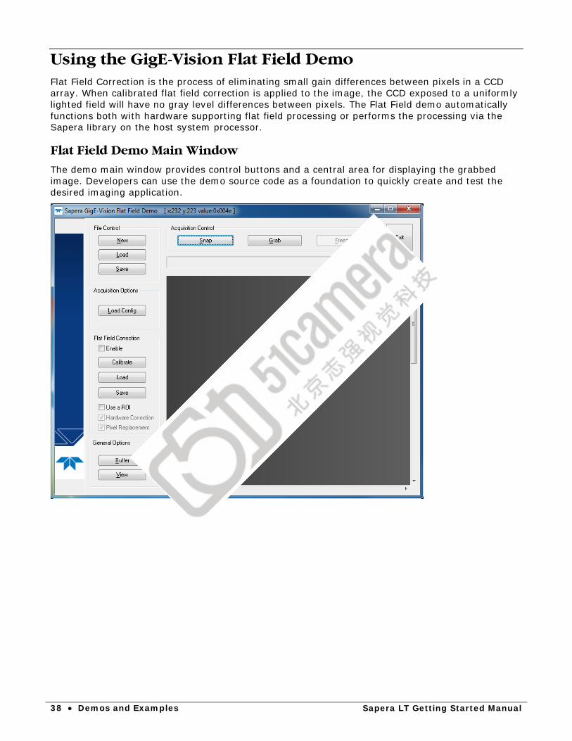
Using the GigE-Vision Flat Field Demo Flat Field Correction is the process of eliminating small gain differences between pixels in a CCD array. When calibrated flat field correction is applied to the image, the CCD exposed to a uniformly lighted field will have no gray level differences between pixels. The Flat Field demo automatically functions both with hardware supporting flat field processing or performs the processing via the Sapera library on the host system processor.
Flat Field Demo Main Window
The demo main window provides control buttons and a central area for displaying the grabbed image. Developers can use the demo source code as a foundation to quickly create and test the desired imaging application.

Sapera LT Getting Started Manual Demos and Examples • 39
Set up Dark and Bright Acquisitions with the Histogram Tool
Before performing calibration, verify acquisition with a live grab. Also at this time make preparations to grab a flat light gray level image, required for the calibration, such as a clean evenly lighted white wall or non-glossy paper with the lens slightly out of focus. Ideally a controlled diffused light source aimed directly at the lens should be used. Note the lens iris position for a bright but not saturated image. Additionally check that the lens iris closes well or have a lens cover to grab the dark calibration image.

40 • Demos and Examples Sapera LT Getting Started Manual
Verify a Dark Acquisition
Close the camera lens iris and cover the lens with a lens cap. Using CamExpert, click on the grab button and then the histogram button. The following figure shows a typical histogram for a Genie grabbing a very dark image.
Important: In this example, the average pixel value for the frame is close to black. Also note that most sensors will show a much higher maximum pixel value due to one or more "hot pixels". The sensor specification accounts for a small number of hot or stuck pixels (pixels that do not react to light over the full dynamic range specified for that sensor).
Sapera LT Getting Started Manual Demos and Examples • 41
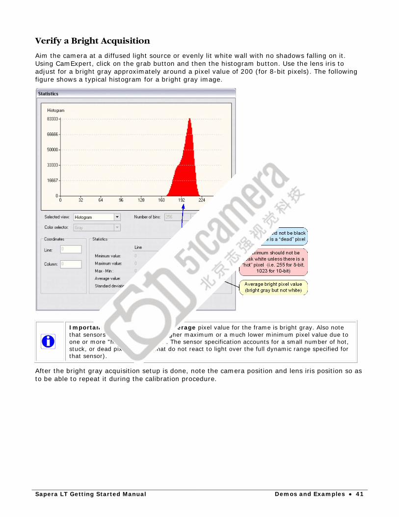
Verify a Bright Acquisition
Aim the camera at a diffused light source or evenly lit white wall with no shadows falling on it. Using CamExpert, click on the grab button and then the histogram button. Use the lens iris to adjust for a bright gray approximately around a pixel value of 200 (for 8-bit pixels). The following figure shows a typical histogram for a bright gray image.
Important: In this example, the average pixel value for the frame is bright gray. Also note that sensors may show a much higher maximum or a much lower minimum pixel value due to one or more "hot or dead pixels". The sensor specification accounts for a small number of hot, stuck, or dead pixels (pixels that do not react to light over the full dynamic range specified for that sensor).
After the bright gray acquisition setup is done, note the camera position and lens iris position so as to be able to repeat it during the calibration procedure.
42 • Demos and Examples Sapera LT Getting Started Manual
Using Flat Field Correction
The demo has typical file and acquisition controls as previously described for the Grab Demo. What is different is the Flat Field Correction control section which has three buttons and a check box. Follow the procedure described below to setup and use flat field correction.
Verify camera acquisition
First ensure that the camera is functioning and that the acquisition board is capturing live images. The Flat Field Demo provides acquisition controls to confirm image capture.
Enable
Before activating flat field or flat line correction, follow the calibration procedure described in this section (see "Flat Field Calibration "). To use real time flat field correction, first click in the Enable box. Then do image snaps or continuous live grab.
Save
Click on the Save button to store files with the flat field gain and offset data gathered with the calibration procedure. Files are saved as .bmp images and can be named as required to reference the camera used.
Load
Click on the Load button to retrieve files with the flat field gain and offset data gathered with the calibration procedure.
Flat Field Calibration
Calibration is the process of taking two reference images, one of a dark field – one of a light gray field (not saturated), to generate correction data for images captured by the CCD. Each pixel data is modified by the correction factor generated by the calibration process, so that each pixel now has an identical response to the same illumination.
The calibration process for an area scan camera can be over the whole frame or a selected number of lines within the frame. For line-scan cameras the user simply selects the number of input lines to average. The calibration control overview follows.
Click the Calibrate button. The calibration window opens as shown.

Sapera LT Getting Started Manual Demos and Examples • 43
Setup Before Calibration
• First select the Correction Type as flat field or single flat line. Note that when using a line-scan camera, only flat line calibration is available.
• Video type will default to the acquisition type defined in the loaded camera file. • Set the Number of frames to average during each calibration step. This should be set to
more than one to avoid false data from random pixel noise. • The field for Maximum deviation from average defaults to 25% of the gray level range
captured, (64 for 8-bit capture, 256 for 10-bit capture, and so forth). This value sets the threshold for detecting static dead pixels – both dark or light. Users will need to adjust this field to best isolate dead pixels from their imaging source.
• The field for Maximum percentage of black pixels in corrected dark image defaults to 2. A high percentage of 0 value pixels should be avoided so that gain adjustments can be properly calibrated.
• When doing a single line calibration to apply to the captured frame, use the two selection fields Number of lines to average and Vertical offset from top, to select which video line will be used.
44 • Demos and Examples Sapera LT Getting Started Manual
Calibration Procedure
• Setup the camera to capture a uniform dark image. Black paper with no illumination and the camera lens’ iris closed to minimum can provide such a black image.
• Click on Acquire Black Image. The flat field demo will grab a video frame, analyze the pixel gray level spread, and present the statistics. If acceptable, use the image as the black reference.
• Setup the camera to acquire a uniform white image (but not saturated white). Even illumination on white paper can be used. It is preferable to prepare for the white level calibration before the calibration procedure.
• Click on Acquire Bright Image. The flat field demo will grab a video frame, analyze the pixel gray level spread, and present the statistics. If acceptable, use the image as the white reference.
• Test the calibration by enabling flat field correction during a live grab. If necessary, adjust the dead pixel detection threshold and repeat the calibration.
• Save multiple versions of calibration data to compare for best imaging or for different imaging setups.
Sapera LT Getting Started Manual Demos and Examples • 45
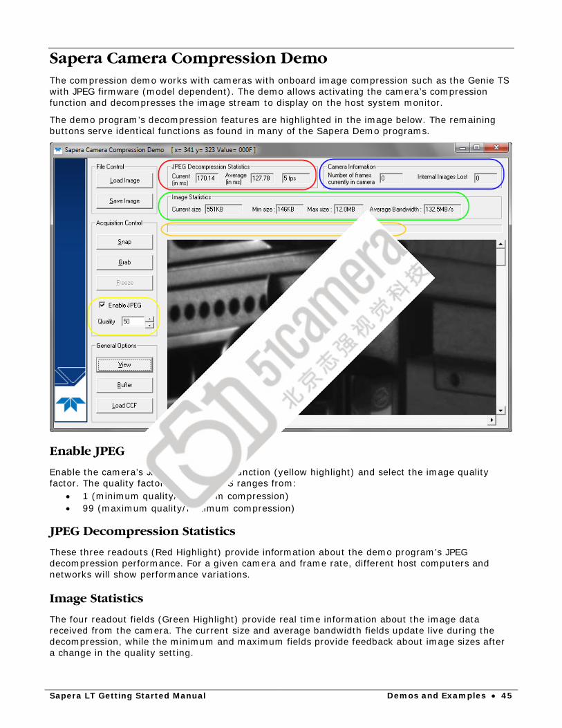
Sapera Camera Compression Demo The compression demo works with cameras with onboard image compression such as the Genie TS with JPEG firmware (model dependent). The demo allows activating the camera’s compression function and decompresses the image stream to display on the host system monitor.
The demo program’s decompression features are highlighted in the image below. The remaining buttons serve identical functions as found in many of the Sapera Demo programs.
Enable JPEG
Enable the camera’s JPEG compression function (yellow highlight) and select the image quality factor. The quality factor for a Genie TS ranges from:
• 1 (minimum quality/maximum compression) • 99 (maximum quality/minimum compression)
JPEG Decompression Statistics
These three readouts (Red Highlight) provide information about the demo program’s JPEG decompression performance. For a given camera and frame rate, different host computers and networks will show performance variations.
Image Statistics
The four readout fields (Green Highlight) provide real time information about the image data received from the camera. The current size and average bandwidth fields update live during the decompression, while the minimum and maximum fields provide feedback about image sizes after a change in the quality setting.
46 • Demos and Examples Sapera LT Getting Started Manual
Camera Information
The two camera information fields (Blue Highlight) provide camera internal buffer information. The Genie TS used in this example has an internal circular buffer for outgoing image data in cases where the network or host computer are too busy to receive incoming packets. If the camera internal buffers are all filled and subsequent image frames overwrite previous frames, the image lost counter is incremented.
Message Area
The unlabeled field (Orange Highlight) can have messages about the demo program status, concerning non-typical events.
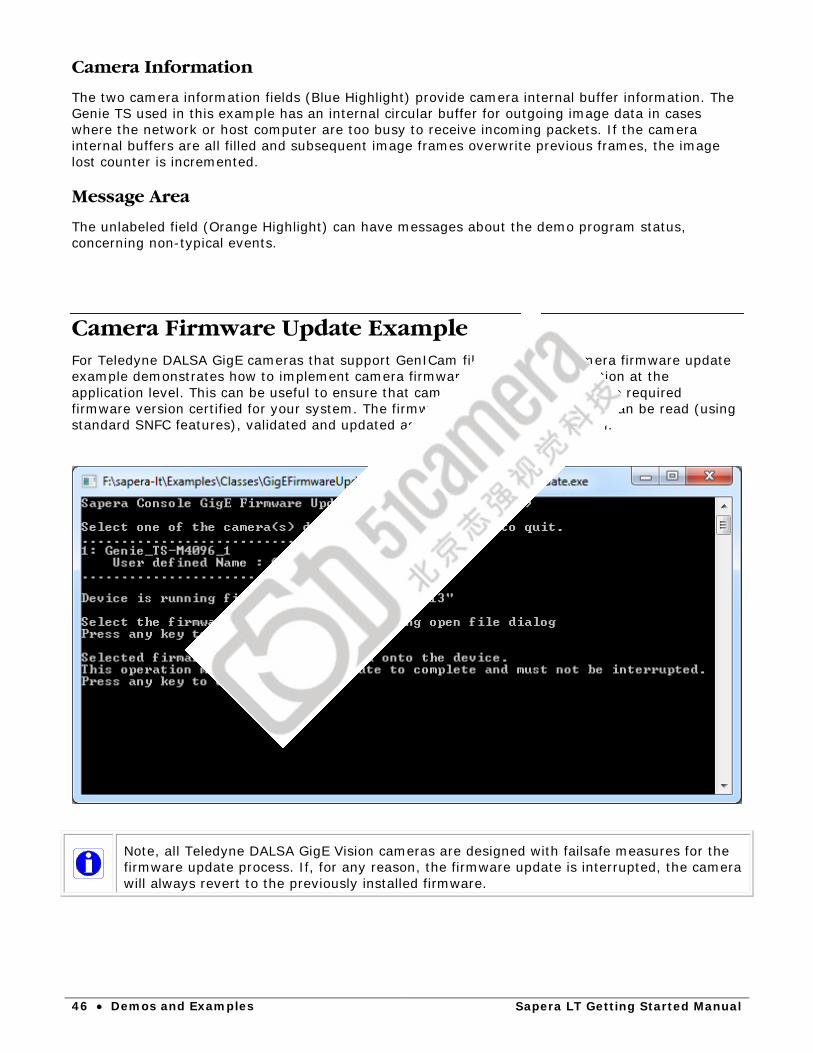
Camera Firmware Update Example For Teledyne DALSA GigE cameras that support GenICam file access, the camera firmware update example demonstrates how to implement camera firmware updates and validation at the application level. This can be useful to ensure that cameras are equipped with the required firmware version certified for your system. The firmware version on the camera can be read (using standard SNFC features), validated and updated as required by your application.
Note, all Teledyne DALSA GigE Vision cameras are designed with failsafe measures for the firmware update process. If, for any reason, the firmware update is interrupted, the camera will always revert to the previously installed firmware.
Sapera LT Getting Started Manual Appendix: File Locations • 47
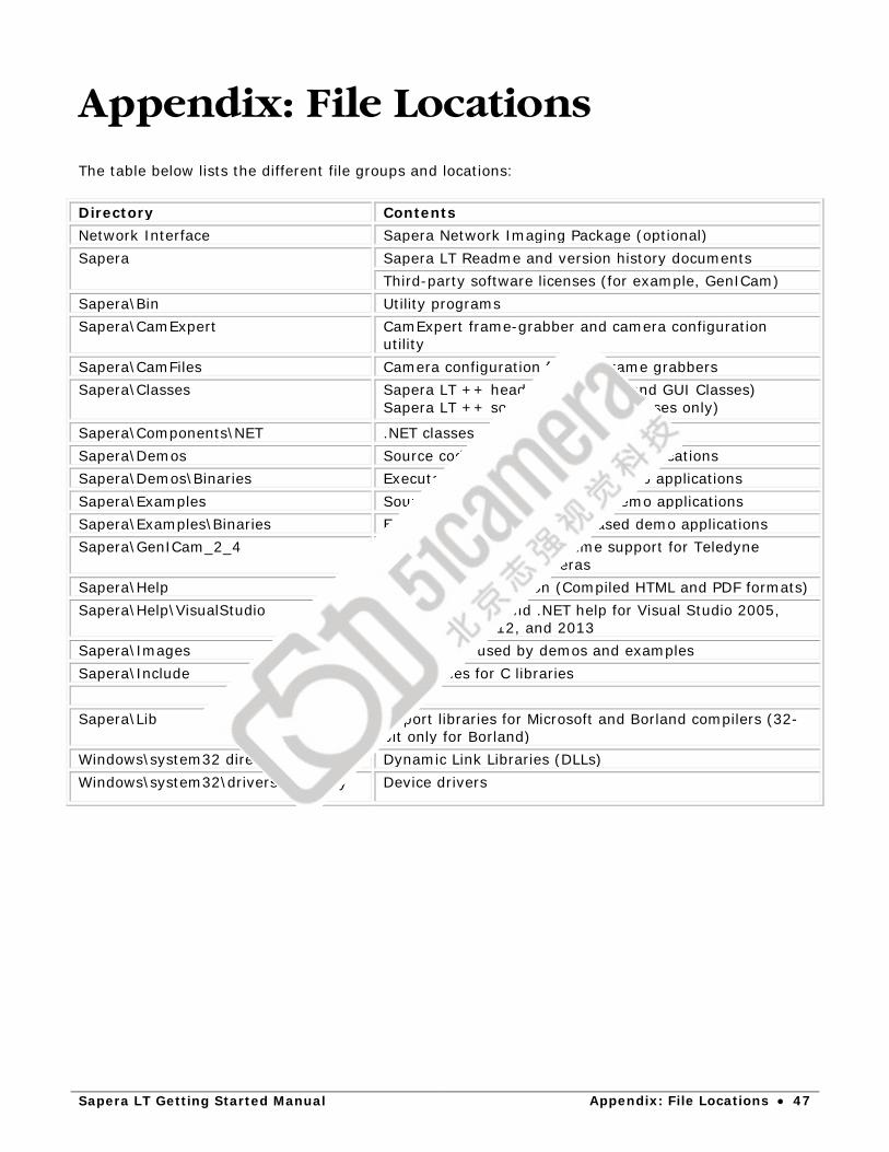
Appendix: File Locations
The table below lists the different file groups and locations: Directory Contents Network Interface Sapera Network Imaging Package (optional) Sapera Sapera LT Readme and version history documents
Third-party software licenses (for example, GenICam) Sapera\Bin Utility programs Sapera\CamExpert CamExpert frame-grabber and camera configuration
utility Sapera\CamFiles Camera configuration files for frame grabbers Sapera\Classes Sapera LT ++ header files (Basic and GUI Classes)
Sapera LT ++ source code (GUI Classes only)
Sapera\Components\NET .NET classes Sapera\Demos Source code for GUI-based demo applications Sapera\Demos\Binaries Executable files for GUI-based demo applications Sapera\Examples Source code for console based demo applications Sapera\Examples\Binaries Executable files for console based demo applications Sapera\GenICam_2_4 GenICam CLProtocol run-time support for Teledyne
DALSA CameraLink cameras Sapera\Help On-line documentation (Compiled HTML and PDF formats) Sapera\Help\VisualStudio Integrated C++ and .NET help for Visual Studio 2005,
2008, 2010, 2012, and 2013 Sapera\Images Images files used by demos and examples Sapera\Include Header files for C libraries Sapera\Lib Import libraries for Microsoft and Borland compilers (32-
bit only for Borland) Windows\system32 directory Dynamic Link Libraries (DLLs) Windows\system32\drivers directory Device drivers
48 • Contact Information Sapera LT Getting Started Manual
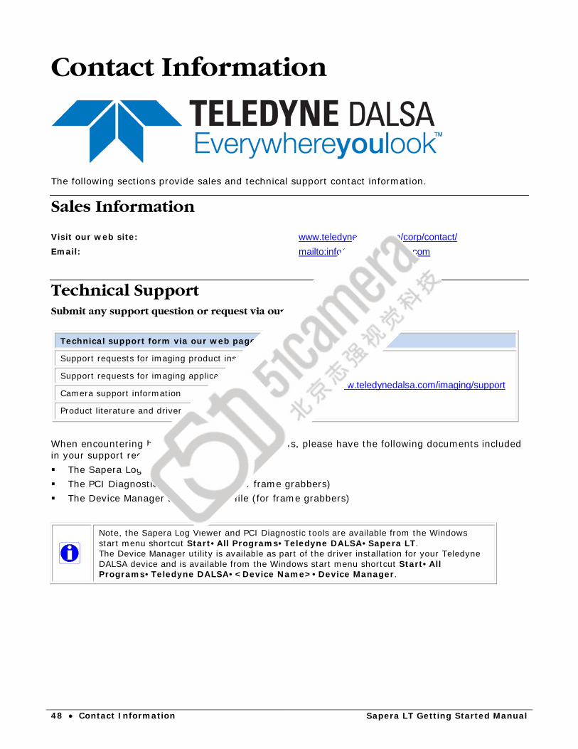
Contact Information
The following sections provide sales and technical support contact information.
Sales Information Visit our web site: www.teledynedalsa.com/corp/contact/ Email: mailto:[email protected]
Technical Support Submit any support question or request via our web site:
Technical support form via our web page:
Support requests for imaging product installations
http://www.teledynedalsa.com/imaging/support Support requests for imaging applications
Camera support information
Product literature and driver updates
When encountering hardware or software problems, please have the following documents included in your support request: The Sapera Log Viewer .txt file The PCI Diagnostic PciDiag.txt file (for frame grabbers) The Device Manager BoardInfo.txt file (for frame grabbers)
Note, the Sapera Log Viewer and PCI Diagnostic tools are available from the Windows start menu shortcut Start•All Programs•Teledyne DALSA•Sapera LT. The Device Manager utility is available as part of the driver installation for your Teledyne DALSA device and is available from the Windows start menu shortcut Start•All Programs•Teledyne DALSA•<Device Name>•Device Manager.