sapca code of practice for the construction of outdoor ...€¦ · the sapca code of practice for...
TRANSCRIPT

SAPCA Code of Practice for the Construction of Outdoor Multi Use Games Areas Copyright © The Sports and Play Construction Association All rights reserved. No part of this publication may be reproduced in any form or by any means without the prior permission of the Sports and Play Construction Association. Published by The Sports and Play Construction Association 1st Edition, Version 1 (May 2014) ISBN: TBC Disclaimer The Sports and Play Construction Association (SAPCA) does not accept any liability for the design or construction of any facilities, or the actions of any contractors employed, as a result of, or in connection with, any information provided in this publication. Some surfacing system products and designs, available to potential clients may be covered by Patents; clients should ensure that the use of similar products does not infringe any patents held by manufacturers or installers. The Sports and Play Construction Association (SAPCA) does not accept any liability for choice of surfacing systems infringing any current or future patents.

The SAPCA Code of Practice for the Construction of Outdoor Multi Use Games Areas
2 May 2014
Contents Introduction Notes on the Code of Practice The Sports and Play Construction Association (SAPCA)
SAPCA’s Aims and Objectives Further information
Prologue
A Project Overview Section One: What is a MUGA? 1.1 Introduction 1.2 The Choice of MUGA 1.3 Existing guidance and standards 1.4 Types of MUGA surfacing
Type 1 - Open textured porous macadam areas (possibly painted) Type 2 – High grip open textured porous macadam areas (possibly painted) Type 3 – High grip finish polymeric surfaces Type 4 - Polymeric surfaces Type 5 – Sand filled synthetic turf areas with a shockpad. Type 6 – Sand filled synthetic turf without with a shockpad. Type 7 – Sand dress synthetic turf areas with a shockpad Type 8 – Third generation (long pile) synthetic turf Type 9 – Needle-punch carpets
1.4.1 Macadam Surfaces (Type 1 and 2) 1.4.2 Polymeric Surfaces (Type 3 and 4) 1.4.3 Synthetic Turf surfacing (Types 5 - 8)
Non-filled (often called Water-based) Sand-filled Sand-dressed Long pile - third Generation (3G)
1.4.4 Needle-punch 1.4.5 Shockpads
Pre-fabricated construction In-situ construction
1.5 Use of MUGAs for non-sporting activities

The SAPCA Code of Practice for the Construction of Outdoor Multi Use Games Areas
3 May 2014
Section 2 - General Construction Requirements 2.1 Design Considerations
2.1.1 Project Brief 2.1.2 Preliminary Investigations
2.2 Site considerations and location
2.2.1 Good Locations for a MUGA 2.2.2 Locations to avoid when locating a MUGA 2.2.3 Local Infrastructure
2.3 Size, orientation and gradients 2.4 Drainage 2.5 Sub-bases 2.6 Edge Kerbs 2.7 Base construction options 2.8 Macadam (bases playing surfaces) 2.9 Paint coatings for macadam MUGAs (types 1 and 2) 2.10 Playing Lines 2.11 Corrective/Remedial Action 2.12 Quality Control
2.12.1 Workmanship 2.12.2 Performance testing on completion
2.13 Fittings and Equipment 2.14 Surround Fencing 2.15 Sports Lighting Section 3 - Maintenance
Appendix A - Performance and construction requirements for MUGAs, types 1 to 9
Appendix B – typical MUGA layouts
Appendix C – typical design criteria of MUGA base constructions
The SAPCA Code of Practice for the Construction of Outdoor Multi Use Games Areas
4 May 2014
Introduction The Sports and Play Construction Association (SAPCA) has produced this document to provide prospective clients and specifiers with guidance on the basic construction requirements and specifications currently employed in building an Outdoor Multi-Use Games Area. The document calls on the experience of our member companies who have constructed a wide range of installations for a variety of clients over many years. The requirements of the various sports’ governing bodies and the relevant standards organisations are incorporated, where appropriate, in the document. Whilst it is not intended that this document should become part of a contract, it is hoped that it will prove useful in the selection of an appropriate system and form a useful reference in the design and construction process. SAPCA recommend that SAPCA Members of the MUGA Division or Professional Services Division be retained to provide the necessary level of expertise in the design and construction sports facilities, ensuring compliance with all of the current legislation. In the case of Outdoor Multi-Use Games Areas, where the appropriate choice of surfacing for the intended usage is vital to the success of any project, professional advice from experienced contractors and consultants is essential. Notes on the Code of Practice
1. This Code of Practice is intended for use by organisations considering the construction of a multi-games use area, architects and consultants designing and specifying such facilities and sports surfacing contractors building them. The Code of Practice should not be used by clients as a substitute for carrying out appropriate surveys and obtaining professional advice in individual circumstances or as a works specification. Although the Code of Practice has been produced by reference to facilities constructed under normal climatic conditions in the United Kingdom, the Sports and Play Construction Association cannot accept any responsibility whatsoever for any loss, damage or injury whatsoever arising from reliance on the guidance within the Code of Practice.
2. The Code of Practice provides minimum guideline specifications which members of the Sports
and Play Construction Association are committed to meet. As guideline specifications, however, they do not supersede a reasonable interpretation of the specification and terms of contract applying in each contract. For individual projects, variations in climate, soil conditions, topography, planning constraints and other site-specific conditions may necessitate standards of specification greater than those recommended in the Code of Practice.
3. Parties not experienced in synthetic sports surfacing construction are strongly advised to
consult qualified sports facility construction consultants and contractors. The Sports and Play Construction Association can provide details of experienced contractors and consultants. A up-to-date list can also be found on the SAPCA web site www.sapca.org.uk
4. Whilst the term ‘asphaltic concrete’ is the internationally accepted technical name for all
surfaces which are composed of a mixture of bitumen and stone, this Code of Practice uses the generic term ‘macadam’, as this is still the commonly used name for asphalts within the UK.

The SAPCA Code of Practice for the Construction of Outdoor Multi Use Games Areas
5 May 2014
5. In accordance with common practice within the construction industry (used, for example, in BS EN 13108 for Asphaltic Concretes), the depth of any individual construction layer is specified within the Code of Practice as the nominal compacted depth. The nominal depth can be regarded as the design depth of a layer of construction within an outdoor Multi-Use Games Area.
6. The information contained within the Code of Practice, whilst accurate at the time of
publication, may be subject to change at a future date. Due to changing technology and new developments in construction methods as well as the changing requirements of the sports’ governing bodies and relevant British Standards, revisions to the recommendations are likely, and only the most recent edition of the Code of Practice should therefore be used.
7. A permanent joint technical committee will keep under review the use of the Code of Practice
and will consider any suggestions for amendment, which should be addressed to the Technical Committee Chairman, The Sports and Play Construction Association, Federation House, National Agricultural Centre, Stoneleigh Park, Warwickshire CV8 2RF. Revisions to the Code of Practice will be made when it is considered appropriate.
8. Due to the fact that many of the processes used in constructing artificial sports surfacing
systems are highly susceptible to weather conditions such as temperature, humidity, rainfall, etc., it is advisable to check with a specialist SAPCA Principle Contractor within the MUGA’S Division or the Professional Services Division, as to the most suitable time of year for the installation of their proprietary product.
9. Many planning authorities now publish very specific local planning requirements in the form
of framework documents and development plans; these will include requirements for many types of outdoor sports facilities. The design of most elements of a Multi-Use Games Area are likely to come under scrutiny, such as fencing, floodlighting, hard surfaces areas, landscaping, planting and drainage. It is essential that the designer of a facility has the experience and knowledge to undertake a full design at planning stage. They are likely to have to prove that the design meets all the requirements and may have to submit calculations to prove compliance.
10. The Construction Design and Management Regulation 2007, require that a CDM coordinator
be employed by the client during the design, specification, tendering and construction of any construction project that is likely to involve more than 30 working days or 500 person days. The CDM coordinator’s role is that of ensuring all H&S paperwork is in place, that it meets the minimum requirements of the regulations and all paperwork is passed to the client, the designer and the contractor when required. It is the client’s duty to ensure that a CDM coordinator is employed for the project and that they have full knowledge of their own responsibilities under the regulations.

The SAPCA Code of Practice for the Construction of Outdoor Multi Use Games Areas
6 May 2014
The Sports and Play Construction Association (SAPCA) As the recognised UK trade association, SAPCA fosters excellence, professionalism and continuous improvement throughout the sports and play construction industry, in order to provide the high quality facilities necessary for the success of British sport. SAPCA’s Aims and Objectives
To promote high standards of design, construction and workmanship for sports facilities in the UK.
To regulate the industry through the vetting and monitoring of SAPCA members. To participate fully in the development of British, European and other Standards for the
construction and performance of sports facilities, for all levels of play. To liaise closely with the governing bodies of sport, both nationally and internationally. To encourage the use of new technology in the design and construction of sports facilities. To provide and support training and education for the industry’s workforce. To provide a strong voice for the sports construction industry in the UK.
www.sapca.org.uk The SAPCA web site provides a wealth of valuable information for anyone involved in the development of sports facilities. Visit www.sapca.org.uk - for Industry News, Technical Guidance, Exhibitions & Events, the SAPCA Membership Database, and more. Visitors are invited to subscribe to the free SAPCA News Update service, for regular news bulletins. Further information The Sports and Play Construction Association operates through its own full-time administration. For further information, including a list of members, please contact SAPCA at the headquarters address below. Alternatively, please visit the SAPCA web site www.sapca.org.uk The Sports and Play Construction Association Federation House Stoneleigh Park Warwickshire CV8 2RF Telephone: 024 7641 6316 Fax: 024 7641 4773 E-mail: [email protected] Web: www.sapca.org.uk

The SAPCA Code of Practice for the Construction of Outdoor Multi Use Games Areas
7 May 2014
Prologue A Project Overview From the first thoughts about the need for an outdoor Multi-Use Games Area, through to the final successful delivery of a quality facility, which will remain at the required standard for years to come, there is a need for a clear understanding of the processes involved. The processes and decisions that need to be undertaken and made can be complex and will depend upon many factors. The diagram on the following page is designed to help potential clients make the correct decisions at the right times by looking at the ideal routes a project may take from proposal to completion and the information required at each stage.

The SAPCA Code of Practice for the Construction of Outdoor Multi Use Games Areas
8 May 2014
Construction of a Sports Facility
This phase prepares the project brief and should includefactors such as; location, sports usage, funding,procurement and project management.
This phase includes the development of a business plan,planning application and, if required, fundingapplication. A consultant is often appointed during thisphase.
Prior to the design phase a detailed site invesitigationshould be commissioned by the client. This includestopographical, geotechnical, electrical and drainagesurveys.
This phase includes the production of a full design,specifications and technical drawings or a scope ofworks document for inclusion in a design and constructtender process. Depending on the size of the project itmay be neceesary to employ a CDM Coordinator at thisstage.
The clients consultant prepares appriotate tenderdocumentation, agrees with the client a suitable list ofcontractors and issues tender invitations. After receivingtenders a review of the submissions is undertaken. Thisincludes tender evaluation, short-listing and eventualcontractor selection.
This phase includes the construction of the facility and will include key stage inspections undertaken to assess build quality, workmanship and design specification conformity.
This section includes the hand-over of the completedproject. After an agreed period following completionperformance testing should be undertaken to ensurespecification compliance. Additionally, a maintenancemanual should be provided by the contractor.
This phase includes the ongoing maintenanceprogramme and warranty period of the instalation. Asrequired performance tests may be undertaken tomonitor surface behaviour.
1. Project Brief
2. Project Feasibility
3. Site Investigation
4. Design Specification
5. Tender Process
6. Construction Period
7. Project Completion
8. Aftercare
The SAPCA Code of Practice for the Construction of Outdoor Multi Use Games Areas
9 May 2014
Section One: What is a MUGA? 1.1 Introduction Multi Use Games Areas (MUGAs) offer a cost-effective solution for communities, schools and other facility providers faced with a wide range of sporting demands and limited space or budgets. When correctly designs they can provide a valuable asset that enhances the local sporting provision. But whilst a MUGA area is often seen as a “safe option”, it must be recognised that there will usually be a need to compromise, primarily in terms of dimensions and the performance of the playing surface to accommodate the sports for which it is proposed. There are also widely differing requirements for the playing surfaces for various sports and many different needs for individual facilities. It is not possible to provide a simple solution or formula that will satisfy every situation. Each facility must be carefully planned according to specific demands and priorities. The guidance in this document is intended to raise a number of important issues, which, if carefully considered and addressed, should help to produce the most suitable design. The advice detailed is based on many years’ experience from contractors, designers, users of MUGAs and sport’s governing bodies. Whilst there are many ways of designing, constructing and surfacing a MUGA these guidelines describe the systems most commonly used and found to provide the playing qualities and experience that users require, whilst at the same time providing a safe and durable environment. Critical to the success of any sports facility is an initial assessment of the likely use of the facility, and the ability of a particular location to meet the strategic and local sport’s needs. It must be determined which sports the facility will provide for, the standards of playing performance needed, and the priorities for usage between them. The choice of sports, and the feasible balance between them, may also depend on the different levels of income generation that are possible. The initial planning stage should also include a thorough assessment of the proposed management and operation of the new facility. In many ways the construction and performance of a synthetic turf MUGA is similar to a synthetic turf pitch, but there are differences. These primarily relate to the design of the drainage and foundation layers and the types of fencing and floodlighting used. As a general rule any facility surfaced with macadam or polymeric surfacing is considered to be a MUGA, as are synthetic turf areas of less than 3000 m2. If you are considering a synthetic turf pitch with an area greater than 3000 m2 it is strongly recommended you refer to the ‘SAPCA Code of Practice for the Construction and Maintenance of Synthetic Turf Sports Pitches’ which is available from the SAPCA website (www.sapca.org.uk). 1.2 The Choice of MUGA It is important at the briefing and design stages of a MUGA development to consider issues that might have a direct impact on the installation and operation. Critical consideration should be given to:
The predominant sporting use The degree of intensity of use The sports performance and playability characteristics required The intended maintained lifespan The sinking fund requirements (including full economic cost considerations)
The SAPCA Code of Practice for the Construction of Outdoor Multi Use Games Areas
10 May 2014
The most commonly played sports on multi-sports games areas are tennis, netball, basketball, soccer (including five-a-side, futsal, etc…) and field hockey. Other sports that might also be played include rugby (tag rugby), rounder’s, athletics practice, tri-golf, roller hockey, volleyball and many other sports and activities. The need for a facility to compromise arises mainly due to the choice of the principle sports playing performance requirements, as certain surface types are more suitable than others for different sports. The interactions between the player and surface and the interactions between the ball and surface need to be considered. Table 1 details the principal properties for the main sports normally played on MUGAs. One of the important issues relating to the choice of surface is the need for some form of shock absorbency (or cushioning), for which there can be conflicting requirements between the sports. On the one hand there are clear benefits for participants in protection from injury, but too much cushioning may be detrimental to the performance of certain sports, such as tennis, basketball, netball and football where the ball is required to bounce in varying degrees. Other sports, especially Netball, and to a lesser degree tennis, require high levels of grip from the surface to enable the sports to be played in a satisfactory way. Not only do these high levels of grip often require specialist finishes to the playing surface, but the ability of surfaces to retain the high grip is greatly influenced by the other sports played on the MUGA and the types of footwear worn. It is increasingly possible to quantify the playing performance of sports surfaces, using a series of standard test methods to measure the different characteristics and a number of sports governing bodies can provide guidance on the individual recommendations for their own sports. This guidance has been incorporated into this Code of Practice as appropriate. The very term Multi Use Games Area (MUGA) implies several sports are to be played in one area. It is important at the design stage, which is the priority sport and what performance characteristics of the secondary sports can be compromised in the choice of the playing surface.

The SAPCA Code of Practice for the Construction of Outdoor Multi Use Games Areas
11 May 2014
Table 1 - Desirable surface characteristics for different sports
Property Tennis Netball Football
(all types) Basketball Hockey
Rugby (training)
Athletics (training)
Good foot grip X X XX X X
Firm surface to give good ball rebound
X X X
Moderate shock absorption to reduce impact forces when running
XX X
High shock absorption to protect players when the fall
XX XX
Nonabrasive surface XX X XX
Porous surface X X X X X X
X = desirable XX = considered essential

The SAPCA Code of Practice for the Construction of Outdoor Multi Use Games Areas
12 May 2014
1.3 Existing guidance and standards This Code or Practice provides an introduction to the design and construction of outdoor multi-use games areas. Reference should be made, as appropriate, to other relevant sources of information, including: British, and other technical standards; industry and other SAPCA Codes of Practices; Sport England’s Technical Guidance Notes; and information leaflets and technical requirements for the performance of playing facilities produced by individual national and international governing bodies of sport. Different sports require separate playing characteristics, and their respective governing bodies stipulate precise requirements. Choosing a priority sport may mean that certain playing characteristics are not ideal for, or even not compatible with, other sports. Individual specifiers should take account of the expected standard of play on the facility being constructed to ensure that, for cost efficiency reasons, the appropriate level of performance standard is specified. Some governing bodies specify different performance requirements depending on the quality (level) of sport to be played on it. The aim is to ensure that international-level pitches are not being specified for facilities where community standard use is adequate and often more cost effective. Various types of MUGA’s will meet a range of different performance requirements. If the client wishes to let the contract on a ‘Design and Build’ basis, allowing the contractor to design a system to meet the selected performance requirements, he/she should obtain confirmation, by way of test certificates, that the nominated system will achieve these results. Appendix A – details typical performance requirements for the nine types of MUGAs detailed in this Code of Practice. If, however, the client chooses to specify on a ‘Method’ or ‘Recipe’ basis by specifying the system he/she requires in detail, then the client must be sure that the system specified will meet the performance requirements needed for the MUGA. This will entail retaining an expert with knowledge of MUGA systems for the range of sports played on such surfaces. Retaining such a consultant or contractor may incur a fee, which may be a fixed sum or may be charged as a percentage of the project value but will gave an added guarantee of conformity. When completed facility client may require the facility to be tested by an independent specialist test house, to the relevant performance standard to ensure compliance with the performance and safety criteria specified. Particular attention should be given to the following publications: BS EN 14877 (2006) “Surfaces for Sports Areas – Specifications for Synthetic Surfaces (multi-use)” BS EN 15330-1 (2007) “Surfaces for Sports Areas – Synthetic Turf Surfaces primarily designed for outdoor use – specifications for synthetic turf” BS EN 15330-2 (2008) “Surfaces for Sports Areas – Needle Punched Carpets primarily designed for outdoor use – specifications for needle punch carpets” The SAPCA Code of Practice for the Construction and Maintenance of Synthetic Turf Sports Pitches (available at www.sapca.org.uk)
The SAPCA Code of Practice for the Construction of Outdoor Multi Use Games Areas
13 May 2014
The SAPCA Code of Practice for the Construction and Maintenance of Tennis Courts (available at www.sapca.org.uk) Sport England Design Guidance Note ‘Artificial Surfaces for Outdoor Sport’ 2012 www.sportengland.org Additionally, many national and international governing bodies have requirements for a specific sports usage, which can be obtained directly from the relevant organisation. Such as: - England Netball – Performance Standards for Netball Courts FIFA Quality Concept for Football Turf - Handbook of Requirements International Hockey Federation (FIH) – Handbook of Performance, Durability and Construction Requirements for Synthetic Turf Hockey Pitches International Rugby Board (IRB) Artificial Rugby Turf Performance Specification Rugby Football League (RFL) - Performance and Construction Standards for Synthetic Turf Rugby League Competition and Training Pitches Whilst the information presented within this Code of Practice is taken from the relevant standards above it is highly recommended that information is obtained directly from the source material to ensure it meets the very latest requirements as these documents are updated on a regular basis. Every effort is made to keep the code of practice up-to-date but there will always be a delay in response to updates. 1.4 Types of MUGA surfacing For reference MUGAs can be classified into numerical groups based on their design. Whilst this helps to procure a MUGA it should be noted that as sports surface technology advances manufacturers and contractors are increasingly able to design MUGAs that can be used for a range of applications. Manufacturers can develop bespoke proprietary systems which will provide performance criteria which are suited to a specific application or sport(s) or indeed designed to meet the requirements of several sports. Therefore, it is recommended research is undertaken to evaluate the most suitable system for your particular requirements. Historically MUGAs surfaces have been split into five categories. In this document the classification has been expanded to reflect the technological developments in sports surfacing increasing range of surfaces now being used. Type 1 - Open textured porous macadam areas (possibly painted) Normally used for ball rebound sports where tennis is the priority and sports such as mini-tennis, , and basketball and netball are secondary users. These areas are suitable for wheelchair sports although care is needed in warm weather during the first year of use or subsequent years when high temperature in excess of 23-24⁰C are expectance.

The SAPCA Code of Practice for the Construction of Outdoor Multi Use Games Areas
14 May 2014
Type 2 – High grip open textured porous macadam areas (possibly painted) Designed for ball rebound sports where netball is the priority and sports such as tennis, mini-tennis, and basketball are secondary users. These areas are suitable for wheelchair sports although care is needed in warm weather during the first year of use. Type 3 – High grip finish polymeric surfaces Designed for ball rebound sports where netball is the priority. Sports such as tennis, mini-tennis, and basketball are secondary. These areas are suitable for wheelchair sports. Type 4 - Polymeric surfaces Used for football, basketball and general sports and recreational training and play. Due to their greater shock absorbency and lower surface friction these areas are not recommended for tennis or netball. Type 5 – Sand filled synthetic turf areas with a shockpad. These surfaces are used for sports such as hockey and small-sided football and may also be used for non-contact training for rugby union, rugby league, American Football and many others. Type 6 – Sand filled synthetic turf without with a shockpad. These surfaces are used primarily used for tennis. Whilst they can also be used for sports such as hockey and football, their relative lack of shock absorption does mean they will not comply with the relevant British and sport’s governing body recommendations and this may increase a facility operator’s liability in the event of a player injury compensation claim. Type 7 – Sand dress synthetic turf areas with a shockpad Primarily designed for hockey, these surfaces can possibly also be used for some other sports, although their use on areas subjected to high intensity play can result in them wearing more rapidly than anticipated and potential carpet movement. Type 8 – Third generation (long pile) synthetic turf Developed to replicate the playing characteristics of natural grass, this type of surfacing is now the preferred choice of the FA and RFU for all forms of football and rugby (with a shockpad). They are also used American Football and lacrosse. Some forms may also allow low-level hockey to be played. The surfaces are not suitable for tennis, netball or basketball. Type 9 – Needle-punch carpets This type of surface may be sand filled or bonded to the sub-base. It can be laid with our without a shockpad and depending on the type selected are considered suitable for tennis, netball, hockey and football. Table 2 details the general suitability of the main types of surfaces for a variety of common sports.

The SAPCA Code of Practice for the Construction of Outdoor Multi Use Games Areas
15 May 2014
Table 2 – Principal playing surfaces verses sports suitability
Sports Surface MUGA Type
Tennis Netball Football Basketball Hockey Rugby
Training Athletics Training
Macadam – standard grip 1 1 3 4 2 4 4 4
Macadam high grip finish 2 2 1 4 2 4 4 4
Polymeric – high grip finish 3 2 1 3 2 3 3
(non-contact) 2
Polymeric – standard grip 4 2 3 2 2 3
3 (non-contact)
2
Sand filled synthetic turf with shockpad 5 3 4 3 3 1 3
(non-contact) 3
(excluding spikes)
Sand filled synthetic turf without shockpad 6 1 3 4 3 3 4 3
Sand dressed synthetic turf with shockpad
7 3 3 4 3 1 3 (non-contact)
3 (excluding
spikes)
3G synthetic turf 8 4 4 1 4 3 1 3
Needle- punch synthetic with shockpad
9 2 2 3 3 2 3
(non-contact)
3 (excluding
spikes)
1 = preferred surface 2 = suitable surface 3 = possible surface although not
recommended by sports governing bodies
4 = considered unsuitable

The SAPCA Code of Practice for the Construction of Outdoor Multi Use Games Areas
16 May 2014
1.4.1 Macadam Surfaces (Type 1 and 2) Macadam surfaces may take the form of dense or porous macadam. Whilst the former may provide a more durable surface and is typically laid on school playgrounds and car parks, its inability to drain is a major constraint on sports use (porous macadam can be played on in most weather conditions year round). Therefore, porous macadam is considered more suitable and is used on around 90% of all macadam MUGAs and tennis courts in the UK. Porous macadam MUGAs may be colour coated to improve aesthetics and the playing environment. This is achieved by either using pigmented materials to form the macadam or by painting the un-pigmented surface after installation. Although the cost of pigmented macadam may be initially higher the increased durability of the colour may make it more suitable for areas of high use. The demands of netball for a high grip surface make the choice of the macadam surface finish critical whenever this sport is to be played. The ability of painted surface to retain acceptable levels of grip for a reasonable period of time is questionable whenever the area is used for activities that may abrade the high grip finish (such as playing football). In such cases experience has shown the use of a hard angular aggregate (granite) to form the macadam surface is a better way of ensuring a durable surface is provide. Unfortunately such aggregates are not always readily available in certain regions of the United Kingdom without having to pay a premium. 1.4.2 Polymeric Surfaces (Type 3 and 4) Normally formed from a mixture of polymeric binder and rubber granules either as prefabricated rolls or laid in-situ with a mini-paving machine, polymeric surfaces have a degree of inherent shock absorption, which makes them more desirable for sports in which players are likely to fall onto the surface. To provide the high degree of slip resistance required by sports such as tennis and netball a specially modified final coating can be applied to the surface, although the use of this surface for ball contact sports will cause a rapid reduction in its slip resistance. Consequently, combining sports such as five-a-side football and netball is not recommended. Some forms of thicker polymeric surfacing are also capable of taking a running shoe spike. To ensure the surfacing has acceptable durability and resistance to weathering all forms of polymeric surfacing should satisfy the laboratory and field test requirements of BS EN 14877 (2013 edition). 1.4.3 Synthetic Turf surfacing (Types 5 - 8) The definition of a synthetic turf is ‘a sports surface comprised of a carpet of tufted, knitted, woven, needle punched or fibre bonded construction whose pile is designed to replicate the appearance and behaviour of natural grass. With pile heights ranging from 10mm (tennis quality) to 60mm plus (rugby grades) there are many different types of synthetic turf with a range of properties, and advantages and disadvantages. Variables include the polymer used for the fibre yarn (such as polyethylene, polypropylene and nylon), the cross-sectional area of the individual ribbons of fibre, the method of carpet manufacture, pile height, pile density and choice of infill. Historically, the majority of MUGAs have been surfaced with tufted sand filled carpets. Experience has shown this form of carpet to have good durability and performance when used in the extreme wear conditions, which are often experienced on MUGAs. The development of longer pile (3G) surfaces

The SAPCA Code of Practice for the Construction of Outdoor Multi Use Games Areas
17 May 2014
has, however, increasingly seen these types of surface being used when football or rugby are the principal sport. Irrespective of which type of synthetic turf is selected to ensure the surfacing has acceptable durability and resistance to weathering all forms should satisfy the laboratory and if required field test requirements of BS EN 15330-1 (2013 edition) Non-filled (often called Water-based) The original (or first generation) form of synthetic turf; these surfaces are manufactured with a short dense pile. Now primarily used for top-level hockey most unfilled products require the use of water to provide acceptable levels of foot grip (considered too high when dry). They are now often referred to as `wet fields` or `water-based`. The water is applied via an irrigation system to the surface immediately before play. The presence of water reduces the player/surface friction, modifies the speed of the hockey ball and cools the surface in hot climates. When designing a non-filled installation, due consideration must therefore be given to the means of applying sufficient water over a short period of time normally via an irrigation system. This, together with the lack of support of infill to provide ballast to the carpet to help withstand the forces applied to the surface through play normally mean the use of this type of surface is unsuitable for MUGAs in most situations. Sand-filled The second generation of synthetic turf, the construction has a longer (typically 18 - 25mm) and more open pile structure than non-filled surfaces, which allows the carpet pile to be in filled with sand. This provides a durable, cost effective surface that can be used for a number of sports at a reasonable level of play. Most carpets are tufted from polyethylene, polypropylene or mixed co-polymer yarns and are infilled with a non-abrasive, well-rounded silica sand, that is dust-free and of uniform grading and density. The sand infill is normally to within 2-3 mm of the fibre tips. As the sand and fibre combine to provide the characteristics of the playing surface it is essential that the level of sand fill is maintained throughout the life of the facility. Sand-dressed A derivative of the sand-filled system is the so-called ‘sand-dressed’ carpets. These are intermediate in properties between traditional filled and non-filled carpets. They have a shorter, denser pile than the standard filled grass systems with a reduced quantity of sand fill. Sand-dressed systems are commonly specified as alternatives to the non-filled, irrigated fields for hockey. Long pile - third Generation (3G) The ‘third generation’ system has found favour with the football and rugby governing bodies and have been approved for football and rugby at the highest level (see FIFA and IRB requirements). Surfaces falling into this category differ from standard sand-filled systems in the height of pile, commonly from 40mm up to 65mm long, and the infill used, normally 2/3 of the pile height. The infill to the 3G system is normally designed to provide all or some (when a shockpad is not incorporated into the surfacing system) of the shock absorbing properties. The infill of rubber or composite granules are sometimes mixed with sand or incorporated with sand in layers. Long pile surfaces are now the surface of choice for sports such as football and rugby due to the performance being closer to natural grass than previous synthetic turfs.

The SAPCA Code of Practice for the Construction of Outdoor Multi Use Games Areas
18 May 2014
1.4.4 Needle-punch (Type 9) Needle-punch carpets have been around for a considerable amount of time; they provide an alternative to sand filled / dressed synthetic turf surfaces, and offer good playing characteristics and durability. Generally they are around 8-16 mm thick and have a fine sand filling applied after installation; although when fully bonded to the base they can be used without and infill. To ensure the surfacing has acceptable durability and resistance to weathering all forms should satisfy the laboratory and field test requirements of BS EN 15330-2. 1.4.5 Shockpads The introduction of a resilient layer between the base construction and the synthetic turf is used to provide a degree of comfort to players and to create defined performance characteristics and safety requirements for specific sports. Correctly designed the inclusion of a shockpad may also help systems to meet the required playing characteristics, extending the life expectancy of the facility. There are a number of ways of achieving this resilient layer, with assorted laid in-situ shock-pad systems, prefabricated or combinations of both. Typical components of in-situ systems are rubber crumb/shred mixed with a resin binder. In the case of pre-formed systems, the shock-pad are delivered to site as rolls or tiles of prefabricated material. In the case of in-situ systems, the components are mixed on site and laid to form a continuous layer of material 1.4.5.1 Pre-fabricated construction The type and thickness chosen will be dictated by the priority sport, although several different options may be able to provide a surface system that complies with playing characteristics requirements. Normally supplied as flat rolls or as inter-locking tiles these types of shockpad generally have a thickness in the range 10 - 23 mm. Whichever shockpad system is to be installed, a reference sample should be obtained at tender negotiating stage so that the installed shockpad can be checked for consistency of material. Careful monitoring procedures and quality control checks should be in place to ensure that any variations in thickness of an in-situ laid pad do not affect the playing performance and compliance with the reference sample. Whichever pre-fabricated shockpad is to be installed, it must be install in accordance with the manufactures instructions. Each type of shockpad has different features and benefits which the manufacturer will confirm and demonstrate before a choice of system is made. Careful evaluation of pre-fabricated systems and laying processes is essential when making comparisons between products. 1.4.5.2 In-situ construction Shockpads constructed in-situ normally vary in thickness from 15 mm to 30 mm and consist of a polyurethane binder mixed with rubber crumb/shred. The thicker pads also may contain pea gravel or other smaller aggregates. The rubber particle shape, size and grading needs to be considered along with the binder type and content.

The SAPCA Code of Practice for the Construction of Outdoor Multi Use Games Areas
19 May 2014
The precise specification and laying techniques will vary depending on the installer and the priority sport. As with preformed pads, no joint should vary in level by more than 2 mm and the completed mat should comply with the level tolerance requirement of the finished installation. 1.5 Use of MUGAs for non-sporting activities The use of MUGA as a school playground, overflow car park or for other non-sporting activities may result in an unsafe playing surface, will shorten the life of the surface, probably invalidate the manufacturers’ warranty and increase the maintenance demands of the surface. A MUGA should be designed to satisfy a wide range of sporting demands; it should not be extend to a point that becomes unachievable or seriously compromises the integrity of the facility.
The SAPCA Code of Practice for the Construction of Outdoor Multi Use Games Areas
20 May 2014
Section 2 - General Construction Requirements 2.1 Design Considerations Many factors can affect the design of a MUGA and this section looks at a number of elements, which should be considered when developing the design of a proposed project. 2.1.1 Project Brief To enable the correct design of a facility to be established it is essential that the Project Brief encompasses all possible areas which will have to be investigated. One of the very first elements to establish is why the facility is needed. In some cases this may be obvious in others less so. For projects that will require a large amount of grant funding through sports governing bodies or funding agencies initial talks should take place to ensure that the location and initial design meets with their strategic and design requirements. Once this has been established then the brief can be expanded to look at other aspects such as usage patterns, management, procurement route, in house resources, and if required the ability to spend money on initial studies both from a design and business plan point of view. 2.1.2 Preliminary Investigations Many factors can affect the design of a MUGA and this section looks at a number of elements, which should be considered when developing and designing a MUGA. The cost of a new facility is greatly influenced by site conditions. Costs will be much higher for engineering a difficult site, and it should be recognised that some sites are not cost effective to develop as sports facilities. A designer has to consider the following factors:
Topography Site Geotextile characteristics Access Site drainage Electrical supply Water supply Trees Ground conditions
Before starting a detailed design, the designer will require as much information as possible about the site and its surroundings. Allowing sufficient resources for initial information gathering greatly reduces the risk of unforeseen problems, (and increased costs), during, construction or even later. It is strongly recommended that this information be obtained at an early stage of the design process and be made available to all contractors tendering for the construction of the facilities. To confirm the scope of earthworks and the drainage design the following information is required:
Topographic survey Ground and site investigation
To establish how the MUGA will fit into the site an accurate survey will be required that will include the following information:
Detailed levels across the site

The SAPCA Code of Practice for the Construction of Outdoor Multi Use Games Areas
21 May 2014
Site boundaries and existing fences Existing trees together with their species and height Surface features relating to drainage and services such as ditches, manhole covers and overhead
lines; any manhole covers should be lifted and the purpose, contents and depths of holes recorded Any other features such as roads and buildings Services, underground and overhead
Understanding the ground conditions is vital, as the greatest risk of unforeseen problems and additional cost usually lies in the ground. Gathering information is only the first step and may need to be followed by fieldwork and laboratory testing. The most important element in ground investigation is to confirm the nature and characteristics of the underlying soil or rock. This is completed by either boreholes or trial pits to allow close examination of each layer to provide a detailed engineering description in accordance with BS 5930. The information required from a ground investigation will include the following:
Ground strength (CBR’s) Groundwater level The sub-soil hydrolytic conductivity Topsoil thickness Soil particle grading (for coarse-grained soils) Soil plasticity indices (for fine-graded soils). Soil plasticity index is a measure of soil clay content
which is vital to assessing shrinkage potential An engineering description of the ground Surface water outfalls
For more difficult sites such as river flood plains, steeply sloping sites or derelict sites, more extensive site investigation will be required. Professional and site-specific advice is essential. For sites that have previously been landfill sites, a full geo-environmental report and contaminant testing will be required to assess the possibility of moving or remove soils from the site. Furthermore, if floodlighting is to be installed it will be necessary to determine the amount of power required and establish the availability of a suitable supply. 2.2 Site considerations and location The location of the MUGA should be sympathetic to its surroundings and any adjacent infrastructure. Early guidance should be sought on policy and any necessary permission that may be required from the Local Planning Authority. On flat terrain sites, landscaping and mounding can be used to obviate noise breakout and floodlight spillage. The location of the MUGA should not create a vehicle jams when access roads and infrastructure is limited (typically one car per three players, which is doubled in the case of non-staggered changeovers, can be used to assess traffic impact). 2.2.1 Good Locations for a MUGA
Close access to car parks and support facilities (especially where constantly supervised).

The SAPCA Code of Practice for the Construction of Outdoor Multi Use Games Areas
22 May 2014
Good sound absorbing/spectator terracing and banking possibilities e.g. the facility sits in a natural amphitheatre-where it is possible to view activities (even remotely using CCTV) from above and where the facility will be sheltered by the surrounding terrain.
Good access to the facility for people with disabilities. 2.2.2 Locations to avoid when siting a MUGA
Where steep gradients lead to the area, especially at personnel and maintenance vehicle access points.
Where there is poor access to the facility for people with disabilities.
Where the facility is remote of support facilities such as changing accommodation.
In very exposed terrain.
Where it is not possible for access roads/footpaths and maintenance routes to reach the main
personnel/maintenance gates.
Where incoming services (electricity feed cables and water/drainage) will be prohibitively expensive to install.
Where too many site perimeter and internal security/access gates have to be passed, meaning
gates need to be locked and unlocked regularly.
Where it is not possible for a facility supervisor to monitor persons, vehicular and cycle movements (especially on access routes and in relation to changing rooms, parked up cars etc.).
Where emergency vehicles cannot readily get to the facility.
Where users have to traverse naturally turfed areas (mud, debris and contaminants all lead to the
rapid deterioration of the playing surface).
Too close to unstable ground (landslides) or drainage outfalls (back falling or ponding on the MUGA due to blocked drains)
Too close to deciduous (leaf drop in autumn) or leaf sap forming trees
Where non-sports users may be passing and be at risk of injury, through unauthorised entry or
access. Trees adjacent to a site may have the advantage of providing privacy, shelter or screening from a low sun. Their roots, however, can be a threat to the facility itself, by distorting or cracking the surface. This is especially the case for strong-rooted varieties such as poplar, willow and sycamore. Where such a threat exists, preventative action will be necessary, such as tree surgery or the construction of a root guard to inhibit the growth of roots onto the site. This is usually done by digging a trench, cutting any roots in the process and removing them as far as possible to a depth of 1000 mm. There are a number of root guards commercially available, specific guidance on installation should be obtained from the manufacture.

The SAPCA Code of Practice for the Construction of Outdoor Multi Use Games Areas
23 May 2014
Whilst such measures will inhibit root incursion, the only certain preventative measure is repositioning the MUGA, generally to a distance equivalent at least to the potential height of the tree and its full potential canopy width. Branches that overhang sports facilities are usually a cause of various problems, such as the continuous dripping of water and leaf sap, insect secretions and bird droppings. These can result in damage to the playing surface and impaired porosity. It is strongly recommended that overhanging branches be pruned back or, if possible, the facility re-sited. 2.2.3 Local Infrastructure The location should ensure the MUGA is readily accessible, ideally located to the front and/or side of a management facility or site. If this is not possible good supervision and amenity/security lighting and pedestrian/vehicular and cycle routes will be required. Access roads need to be wide enough to be used by visitors, maintenance and emergency vehicles (including equipment attached to a tow bar or on the back of a trailer etc.). Footpaths should be wide enough to ensure wheelchair users can access the facility. Dropped kerbs at crossing points and general access for disabled infrastructure should be DDA compliant as well as satisfying Sport England’s Access requirements as detailed in the Access for Disabled People Guidance Note (www.sportengland.org/resources/download), BS 8300 and Part M of the Building Regulations. A disabled person hard-standing parking bay should be provide allowing direct pathway access to any support facilities and the MUGA. Amenity/security lighting installations should be installed along access routes help to allay any severe contrast of lighting conditions when a user comes away from a floodlit facility. To ensure safe egress from the floodlit area, arrangements should be made to retain a small part of the main lighting in operation for a limited period. This will usually be just prior to the curfew time, if one is imposed by the planning approval. For anything greater than a one-court size of MUGA (and to a degree needs should even be assessed for these) access to support facilities and changing provision is desirable. When synthetic turf surfacing is being used, and in particular those filled with sand and/or rubber, it is advisable to install at all ingress/egress points drained catchment pits and gratings, complete with barrier matting. Certain designs of catchment pits and grilles will also double as animal deterrents, especially if pits are wide enough to prevent them being jumped over and if gates are self-closing. Where the use of a MUGA focuses on the need to cater for team changeovers throughout the day installing a one court ‘rec-zone’ to act as a pre-match warm up and practice area is beneficial. This may be surfaced using a more cost effective surface if budgets are limited but matching the exact MUGA surface is preferable where higher standards of competitive play are envisaged 2.3 Size, orientation and gradients The size of any facility should, where possible, be dictated by the dimensions required by the sports to be played. However where a site may not be large enough for full size facilities, sports governing bodies should be consulted to establish the most appropriate dimensions for the MUGA, especially where funding is being obtained through the governing body. Appendix B shows typical layouts of a variety of MUGAs.

The SAPCA Code of Practice for the Construction of Outdoor Multi Use Games Areas
24 May 2014
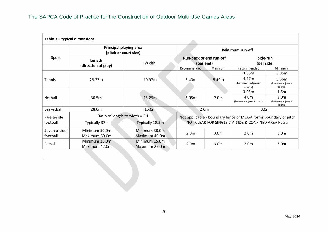
Table 3 shows recommended the sports governing bodies recommended dimensions for playing areas and run-offs. In order to avoid facing directly into low afternoon and evening sun, the preferred orientation for a MUGA’s axis is approximately north south. It is not uncommon for sports governing bodies to specify a maximum fall of 1 % (with a recommended 0.5 %) in any direction, whilst some may have more stringent requirements such as field hockey and tennis. 2.4 Drainage A suitable drainage scheme should be designed and installed which will:
Ensure that all surface water is removed from the site at a rate that will safeguard against surface flooding occurring;
Not allow excess water to remain present in the construction that might result in a reduction of the load-bearing capacity of the formation or in any frost damage to the construction;
Protect the installation from the effects of ground or surface water from the surrounding areas;
Meet the requirements of the Environmental Agency or Local Water Authority, this aspect is usually required at planning stage for most facilities, therefore a drainage design will normally form part of the clients design criteria.
Due to the relatively small dimensions of most MUGAs they do not tend to have any form of sub-area lateral drainage other than a perimeter drain that is laid around one or more sides of the facility. However, larger MUGA’s will have lateral drains incorporated beneath the playing area, the centres of which shall be determined by the composition of the subsoil and the designed infiltration and outfall rates. Centres usually range from 5 m to 15 m. The ends of lateral drains should be capped to prevent contamination, and connectors should be used when joining lateral drains to collector drains. Collector drains should be located on the outside of the perimeter edging. Perimeter drains (which may act as collector drains) should be installed at the toe of any embankments to prevent run-off from surrounding areas. Silt/inspection chambers should be constructed where perimeter/collection drains change direction, and the provision of rodding eyes should be included at the head of collector drain runs for ease of access for maintenance. Drains usually consist of perforated plastic pipes, bedded on, and backfilled with, clean stone which should then be compacted. No drains should have less than 150 mm cover over the top of the pipe, and no drain should be laid to a fall of less than 1:200 unless advised by manufacturers’ instructions. In certain sub-soils where silting-up may be a problem, a geotextile membrane may be used to line the trench prior to backfilling. The installation of a MUGA may disturb any existing land drainage and render it ineffective; where existing land drains are severed, they should be connected into the new perimeter drain. The Environmental Agency and Local Water Authorities now have strict guidance regarding the outfall of drainage systems. Although the design of MUGA are usually porous, by installing a drainage system in order to keep the surface and base dry and therefore not subject to frost heave and possible damage, the design will concentrate the water to one outfall point, traditionally this has discharged

The SAPCA Code of Practice for the Construction of Outdoor Multi Use Games Areas
25 May 2014
into an existing outlet or natural watercourse or if ground conditions permit, soak-aways. However, it is now common practice for planning authorities to submit an application for a MUGA which includes a drainage system to the Environmental Agency or Local Water Authorities for their approval, as part of this process it is likely that they will ask for the drainage design to be proven and they may put limitations on the amount of water that may be discharged to a water course or surface water drain. In such cases it may be necessary to use an attenuation system to store the water prior to discharge. Due regard must be given to location and size of either attenuation systems or soak-aways and to ensure that the calculations regarding their design are undertaken by a drainage expert.
The SAPCA Code of Practice for the Construction of Outdoor Multi Use Games Areas
26 May 2014
Table 3 – typical dimensions
Sport
Principal playing area (pitch or court size)
Minimum run-off
Length (direction of play)
Width Run-back or end run-off
(per end) Side-run (per side)
Recommended Minimum Recommended Minimum
Tennis 23.77m 10.97m 6.40m 5.49m
3.66m 3.05m
4.27m (between adjacent
courts)
3.66m (between adjacent
courts)
Netball 30.5m 15.25m 3.05m 2.0m
3.05m 1.5m
4.0m (between adjacent courts
2.0m (between adjacent
courts) Basketball 28.0m 15.0m 2.0m 3.0m
Five-a-side football
Ratio of length to width = 2:1 Not applicable - boundary fence of MUGA forms boundary of pitch NOT CLEAR FOR SINGLE 7-A-SIDE & CONFINED AREA Futsal Typically 37m Typically 18.5m
Seven-a-side football
Minimum 50.0m Maximum 60.0m
Minimum 30.0m Maximum 40.0m
2.0m 3.0m 2.0m 3.0m
Futsal Minimum 25.0m Maximum 42.0m
Minimum 15.0m Maximum 25.0m
2.0m 3.0m 2.0m 3.0m
.

The SAPCA Code of Practice for the Construction of Outdoor Multi Use Games Areas
27 May 2014
2.5 Sub-bases The MUGA will be subjected to many different stresses throughout its life due to the varying seasons and climatic conditions that occur. These stresses mainly concern the sub-soil on which the MUGA is built, and can include:
Frost heave
Clay shrinkage/swelling
Settlement
Ground loading (above the surface)
Vegetation disturbance (e.g. tree roots/weed growth)
Flooding
Faulty or inadequate drainage
Other types of ground movement
The degree to which the performance and durability of the playing surface will be affected by these forces depends on:
the site conditions e.g. climatic conditions and the type of sub-soil present;
the type and depth of construction.
Certain sub-soils are far more prone to the two main causes of serious problems, frost heave and clay shrinkage, and clearly it is important to determine site conditions before designing the construction. Frost Heave is caused when frost penetrates into susceptible sub-soils that include a lot of fine silty material. The particular pore sizes of these soils draw water by capillary action into the freezing zone, causing ice “lenses” to form which then expand and push up towards the surface. The longer and deeper the period of frost penetration the greater is the effect. After thawing, the surface will eventually settle back but the displacement, and subsequent inconsistent settlement, will leave undulations on the playing surface. Many clay soils are prone to swelling when hydrated, and shrinking and cracking when dehydrated. This will often show as cracking in a lawn during a dry summer. Such cracking and settlement or swelling will transmit through to the surface if an insufficient depth of foundation is provided. The sub-base to any MUGA should therefore be designed to meet the following criteria:
It should be capable of supporting and transmitting to the existing ground the loads of all vehicles, plant, machines and materials to be used in the construction, without causing deformation of the construction;
It should be capable of supporting and transmitting all loads on the playing surface without permanent or long-term deformation of the playing surface. Such loads arise mainly from players and maintenance equipment.
It should ensure that water, whether rainwater or natural ground water, will drain away freely through the sub-base material, either into the natural subsoil or into the drainage system.
A MUGA’s sub-base should be constructed using hard, clean, well-bound, non-frost-susceptible aggregates. These are typically a reduced fines grading (Department of Transport Type 3) aggregate mix or a 28mm to 50mm clean stone capped with a 10mm chipping to act as a blinding layer.
The SAPCA Code of Practice for the Construction of Outdoor Multi Use Games Areas
28 May 2014
The total construction depth (foundation plus surfacing) is critical for several reasons:
the greater the depth the less chance of frost penetrating into the sub-soil;
the effects of any forces superimposed at the surface are generally spread at an angle through the construction and will be dispersed over a much wider area with a thicker foundation (doubling the thickness will reduce the effect of stresses at formation level by a factor of four);
thicker foundations provide greater load-bearing capacity and may allow the use of heavier machinery (e.g. laser-controlled pavers), giving more economic and higher quality surfacing with better surface tolerances.
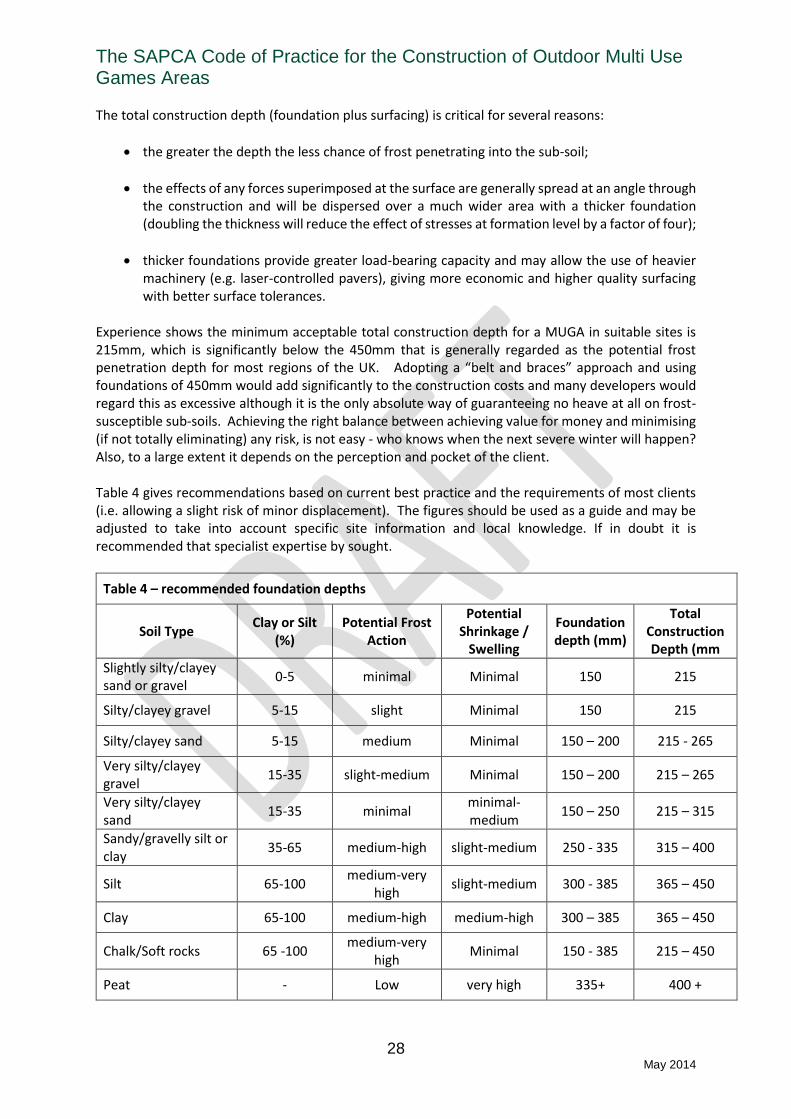
Experience shows the minimum acceptable total construction depth for a MUGA in suitable sites is 215mm, which is significantly below the 450mm that is generally regarded as the potential frost penetration depth for most regions of the UK. Adopting a “belt and braces” approach and using foundations of 450mm would add significantly to the construction costs and many developers would regard this as excessive although it is the only absolute way of guaranteeing no heave at all on frost-susceptible sub-soils. Achieving the right balance between achieving value for money and minimising (if not totally eliminating) any risk, is not easy - who knows when the next severe winter will happen? Also, to a large extent it depends on the perception and pocket of the client.
Table 4 gives recommendations based on current best practice and the requirements of most clients (i.e. allowing a slight risk of minor displacement). The figures should be used as a guide and may be adjusted to take into account specific site information and local knowledge. If in doubt it is recommended that specialist expertise by sought.
Table 4 – recommended foundation depths
Soil Type Clay or Silt
(%) Potential Frost
Action
Potential Shrinkage /
Swelling
Foundation depth (mm)
Total Construction Depth (mm
Slightly silty/clayey sand or gravel
0-5 minimal Minimal 150 215
Silty/clayey gravel 5-15 slight Minimal 150 215
Silty/clayey sand 5-15 medium Minimal 150 – 200 215 - 265
Very silty/clayey gravel
15-35 slight-medium Minimal 150 – 200 215 – 265
Very silty/clayey sand
15-35 minimal minimal-medium
150 – 250 215 – 315
Sandy/gravelly silt or clay
35-65 medium-high slight-medium 250 - 335 315 – 400
Silt 65-100 medium-very
high slight-medium 300 - 385 365 – 450
Clay 65-100 medium-high medium-high 300 – 385 365 – 450
Chalk/Soft rocks 65 -100 medium-very
high Minimal 150 - 385 215 – 450
Peat - Low very high 335+ 400 +

The SAPCA Code of Practice for the Construction of Outdoor Multi Use Games Areas
29 May 2014
The figures given in Table 4 show the design depths for any particular site or soil type. From a construction point of view, however, a tolerance is required on these figures to reflect the practicalities of working on site. It is recommended that at no point on a MUGA should the foundation depth be 25mm below the design depth and that the total area on which the depth is 10% below the design depth should not exceed 10% of the total area. If recycled materials are to be used in the sub-base construction then it is essential that they come from a reputable source and should be graded and certified as meeting the requirements of the Specification for Highways Works series 0700, clause 710. It is recommended that if recycled materials are used then they are topped off with a minimum of 50 mm of virgin rock material, this will help to ensure that, if they have high cement/lime content that calcification of the upper layers does not occur. The presence of metallic materials in recycled materials can also cause problems to the playing surface if it interacts with acidic rain or an alkaline environment and should therefore not be present. The foundation material should be laid in layers not exceeding 150 mm, each layer being compacted before the next is laid. Compaction should be undertaken so that when tested with a lightweight deflectometer (Prima or similar) a target compaction of 60MPa (with no area less than 40MPa) is achieved. The surface level tolerance should be within ±10 mm of the design level, and, when checked with a 3 m straight edge, there should be no deviation greater than 10 mm. In order to prevent contamination from the sub-grade it is normal practice to install a geotextile membrane on the formation prior to installation of the sub-base. Geotextiles are water-permeable fabrics that are laid in sheet form beneath the foundation to provide a number of benefits, including:
isolating the foundation and preventing infiltration and contamination by a silt or clay sub-soil;
increasing of the load-bearing and structural strength of the foundation;
the provision of a “slip sheet” to help to prevent cracks from transmitting from the sub-soil to the surface;
inhibiting possible weed growth from the sub-soil zone.
Although increasing the cost of construction marginally the benefits of using geotextiles are considered such that they should be included in all new constructions. 2.6 Edge Kerbs In order to keep the base, sub-base and surfacing from subsiding at the edges a low retaining kerb should be installed at the edges of the MUGA, this kerb will normally be formed of pre-cast concrete and the most common dimension is 150mm x 50mm, other types of kerbing systems such as in-situ cast concrete or bricks are used in specific circumstances. The level of the top of the kerb should match the type of surfacing being installed, for macadam and polymeric surfaces the top of the kerb should be installed level with playing surface, whereas with synthetic turf the kerb should be installed level with the top of the infill material within the carpet. In some circumstances the edge kerbs may incorporate carpet gripping systems where the infill is insufficient to allow the carpet to remain stable throughout its life. The kerbs shall be well haunched in suitable concrete, derived from the prevailing soil conditions, the bed and haunching may incorporate movement joints at appropriate spacing’s.

The SAPCA Code of Practice for the Construction of Outdoor Multi Use Games Areas
30 May 2014
2.7 Base construction options Once a suitable sub-base has been designed for the specific ground conditions there are two main alternative constructions which could be used for the base: a bound base (engineered) normally of porous macadam, or an unbound (dynamic) base formed either of stone, as a separate layer on top of the sub-base or as an extension to the sub-base. There are also a couple of less common types of base, those formed of sand and also those formed of a mixture of lava and rubber granules. The choice of which type of base should be used for any specific site will depend on many factors. The factors which should be considered when identifying which type of base is suitable are as follows:
Final surface regularity requirements Consistency of playing characteristics Formation susceptibility to movement Longevity of surface tolerances Cost
Bound bases provide a very stable surface. They are essential for maintaining the tight surface level tolerances required for some sports over the life expectancy of the base (around 25-30 years). They are inherently more stable than unbound bases and provide a better guarantee of consistency of playing characteristics over the MUGA surface both initially and during its life. In the case of a synthetic turf MUGA, whether a shockpad is required or the carpet is being laid directly onto the base, a bound base is much easier to install those materials on during the construction process, as the surface does not move under the machinery required. Bound bases also offer better permeability rates over most unbound stone bases as the latter has to be held together with a percentage of fine material in its uppermost layer. Furthermore, it is possible to specify bound bases using international standards, whereas there are no published standards for unbound bases. For certain types of constructions, surfacing and possibly budget constraints the use of unbound stone bases may be preferable. The main advantage of unbound bases is that they can benefit from a lower initial capital cost than bound bases. However, it may be necessary to increase sub-base depths to improve surface level tolerances if poor ground conditions prevail, in which case the benefit of cost may be reduced. Also it may become necessary to rectify deviations in surface regularity during the life of the synthetic surfacing which can be problematic and costly. The design of these types of base has not as yet been specified by any standards organisations or sports governing bodies. Contractors have many differing views on how an unbound stone base should be constructed, generally they are either an extension of the sub-base stone, a layer of clean stone laid and compacted on top of the sub-base or a blinding layer of stone designed to help consolidate and hold together the sub-base stone. If this type of base is being considered or offered by a contractor a full description of the components and design should be obtained. Site checks should also be carried out at stages during their construction to ensure that the design is being correctly adhered to. A further advantage of unbound bases is their ability to deform under high impact loads thus improving player safety (without a shockpad) when a player contacts the surface under heavy impacts. However, repeated impacts and transmission of loads from heavy machinery (including maintenance vehicles) may have a detrimental effect on surface regularity overtime. For all MUGA types other than Third Generation Synthetic Turf (Type 8) a bound (macadam) base construction is recommended. For third generation synthetic turf MUGAs an unbound base can be

The SAPCA Code of Practice for the Construction of Outdoor Multi Use Games Areas
31 May 2014
used in some situations, although the inherent strength and stability a macadam layer provides is always advantageous. 2.8 Macadam (bases and surfaces) The base for a MUGA is normally a porous bound construction consisting or either a single layer 40-50mm thick of open-textured bituminous macadam or two layers (40mm blinding layer and 25mm surfacing course), these can be either machine or hand laid. These forms of construction have gained acceptance due to their ability to offer the greatest possible level of stability to the final surface, resisting frost heave and spreading surface loading. These factors all mean that it is simpler to replace or upgrade the surface of the MUGA when the need arises. On MUGAs on which the macadam surface course is to be the playing surface a 0/6mm grade is used. This is normally an open textured grade of macadam although medium grades may be used where structural strength is the overriding consideration, although it must be appreciated that the ability of a medium grade macadam to allow water to drain through the surface is much less than an open grade and in many cases is best described as semi-porous. Specifications for coated macadam’s include tolerances on the aggregate grading to allow for normal production variations. This will mean that minor variations in texture between different loads of macadam might be apparent in the laid material. However, provided the macadam complies with the required composition specification, its performance should be satisfactory as long as it is well laid and compacted. Macadam’s from different sources may well have different target gradings and to avoid undue texture variations, it is recommended that a single source of supply be used for the surface course on any one MUGA. The question of what is an acceptable texture can be contentious; as many clients fear that an area of macadam with an open texture may have an unacceptable effect on the way a ball rebounds from the surface or the longer-term durability of the surface. When assessing variations in texture the over- riding consideration is does the area affect the way a ball rebounds from the surface? If it does not it is probably acceptable. On MUGAs on which the macadam surface course is not the playing surface an open textured 0/10mm grade is normally used. Aggregate durability Geological formations and deposits, which are quarried, are by their very nature variable. However, by initial selection of source and then by the quarrying and processing operations, producers achieve an acceptable and consistent level of aggregate quality and particularly keep the amount of weak or deleterious aggregate to an absolute minimum. It should be recognized, however, that it is not always possible to completely eliminate weaker aggregate particles. There will, therefore, be the occasional appearance of such weaker aggregate particles in a macadam surface but these do not indicate a significant risk to the performance or durability of the surface. The minimization of these particles, particularly in respect to their negative effect on the appearance of a painted MUGA surface, is controlled by the use of aggregates that conform to the appropriate categories of Resistance to Fragmentation (BS EN 13043-Clause 4.2.2, PD 6682-2 Clause 3.3.1) and durability (BS EN 13043 Clause 4.2.9, PD 6682-2 Clause 3.3.8). The ability of the aggregate in a macadam mix to resist weather and wear is important to the durability of the mix. An adequate level of aggregate strength should be provided by a coarse aggregate that conforms to BS EN 3034 Clause 4.2.2 Resistance to Fragmentation, Category LA30 when tested in accordance with the Los Angeles test method given in BS EN 1097-2.
The SAPCA Code of Practice for the Construction of Outdoor Multi Use Games Areas
32 May 2014
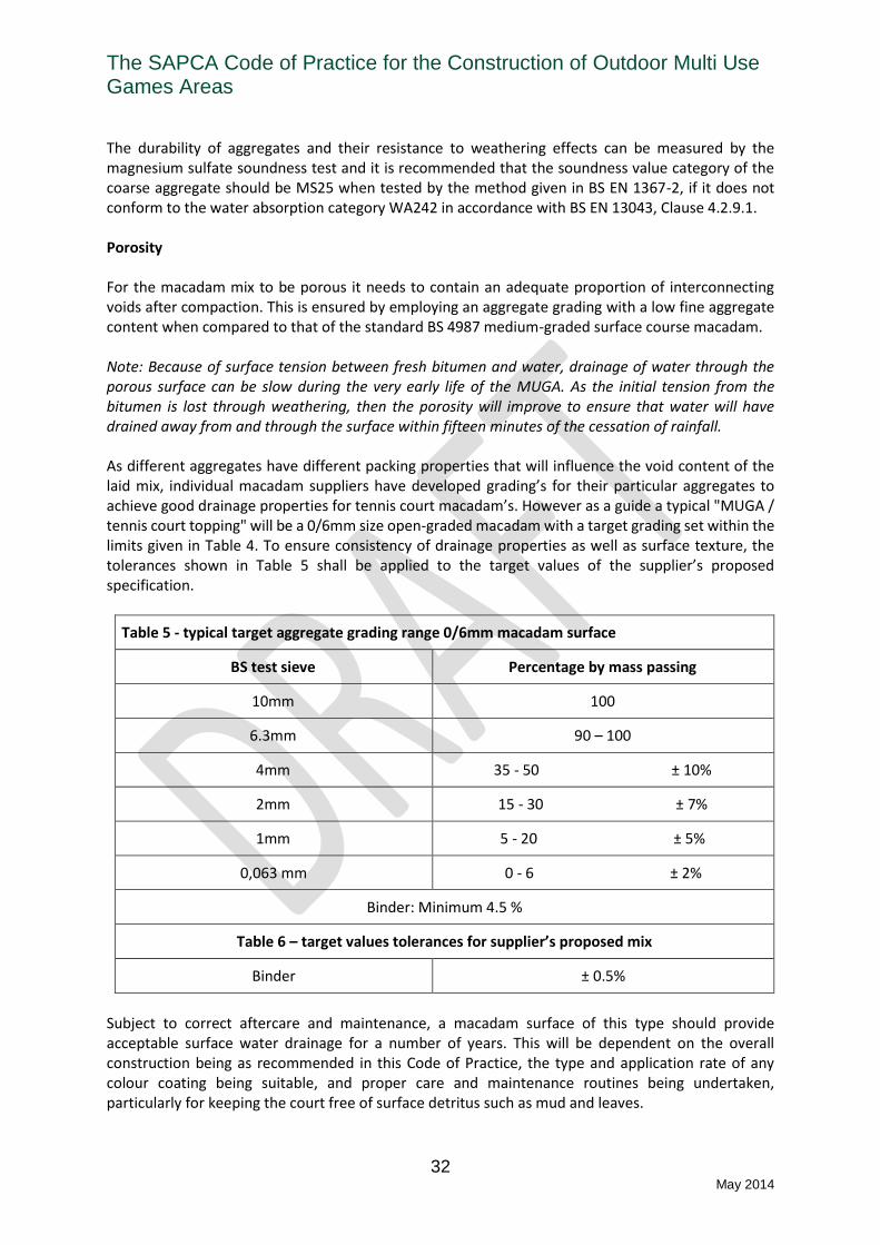
The durability of aggregates and their resistance to weathering effects can be measured by the magnesium sulfate soundness test and it is recommended that the soundness value category of the coarse aggregate should be MS25 when tested by the method given in BS EN 1367-2, if it does not conform to the water absorption category WA242 in accordance with BS EN 13043, Clause 4.2.9.1. Porosity For the macadam mix to be porous it needs to contain an adequate proportion of interconnecting voids after compaction. This is ensured by employing an aggregate grading with a low fine aggregate content when compared to that of the standard BS 4987 medium-graded surface course macadam. Note: Because of surface tension between fresh bitumen and water, drainage of water through the porous surface can be slow during the very early life of the MUGA. As the initial tension from the bitumen is lost through weathering, then the porosity will improve to ensure that water will have drained away from and through the surface within fifteen minutes of the cessation of rainfall. As different aggregates have different packing properties that will influence the void content of the laid mix, individual macadam suppliers have developed grading’s for their particular aggregates to achieve good drainage properties for tennis court macadam’s. However as a guide a typical "MUGA / tennis court topping" will be a 0/6mm size open-graded macadam with a target grading set within the limits given in Table 4. To ensure consistency of drainage properties as well as surface texture, the tolerances shown in Table 5 shall be applied to the target values of the supplier’s proposed specification.
Table 5 - typical target aggregate grading range 0/6mm macadam surface
BS test sieve Percentage by mass passing
10mm 100
6.3mm 90 – 100
4mm 35 - 50 ± 10%
2mm 15 - 30 ± 7%
1mm 5 - 20 ± 5%
0,063 mm 0 - 6 ± 2%
Binder: Minimum 4.5 %
Table 6 – target values tolerances for supplier’s proposed mix
Binder ± 0.5%
Subject to correct aftercare and maintenance, a macadam surface of this type should provide acceptable surface water drainage for a number of years. This will be dependent on the overall construction being as recommended in this Code of Practice, the type and application rate of any colour coating being suitable, and proper care and maintenance routines being undertaken, particularly for keeping the court free of surface detritus such as mud and leaves.

The SAPCA Code of Practice for the Construction of Outdoor Multi Use Games Areas
33 May 2014
Mix durability As long as an adequate binder content is used in the macadam mix and the aggregate is of adequate strength, the mix should be durable and perform to expectations. A minimum binder content of 4.5% is likely to be satisfactory, and the supplier should take account of his production tolerance before setting a target binder content to meet this requirement. The target binder content selected will also be dependent on the particular aggregate type and on the target grading employed. Suppliers will consider all these factors in order to ensure a durable mix. Resistance to softening Softening of a macadam playing surface in hot weather is one of the most common sources of customer dissatisfaction. All macadam mixes will, to a certain extent, soften as the temperature rises and harden as it falls, as the bituminous binder that they contain is a thermoplastic material. The degree of softening will depend on the stiffness of the mix, which is principally governed by the stiffness of the binder used in it, and the nature of exposure to direct sun. For example, a macadam laid in a "sun trap" position will be more prone to softening problems than one laid in a shaded area. Also, macadam mixes stiffen-up in service due to bitumen hardening: the older the surfacing, the less likely it is to be affected by softening. To resist softening, relatively hard bitumen’s need to be used in the macadam mix. It is recommended that a bitumen binder grade no softer than 160/220 penetration is used. To reduce the degree of softening in susceptible areas, a modified binder or additive such as latex or wax may be used. Mixes incorporating latex require higher laying temperatures and laying in cold, wet or windy weather conditions should be avoided and any "double handling" (e.g. wheel barrowing) of the macadam must be kept to a minimum. Transport and material handling Coated macadam’s are transported in insulated lorries which are either double sheeted or utilize the "Easisheet" principle of sheeting to retain the material temperature in transit. Where possible, material should be used direct from the lorry in order to minimize the loss of temperature. When material is tipped on site it should be placed on metal or hard wood sheeting and immediately completely covered with a weatherproof tarpaulin suitably secured to keep it in position. The tarpaulin should be kept in place until all the material has been used, and particularly should be replaced after each batch of material has been removed for laying. Laying and compaction For a porous macadam surface, the macadam binder course and surface course shall be laid at the nominal compacted thicknesses recommended in Table 7. At no point in the construction shall the layer thickness be less than the minimum compacted thickness, which is also stated within Table 7. Compaction is the most critical operation in the construction of any bituminous surface, especially those incorporating macadam’s. The compaction effort brings the aggregate constituents into contact with one another providing the mechanism for load bearing, stability and performance. Compaction should be commenced as soon as possible without undue displacement of the material under the roller. In all cases compaction should be substantially completed whilst the material is above the minimum specified rolling temperature, which varies according to the grade of binder in the mix (see Table 8). Rolling should continue until all roller marks have been removed, however continued
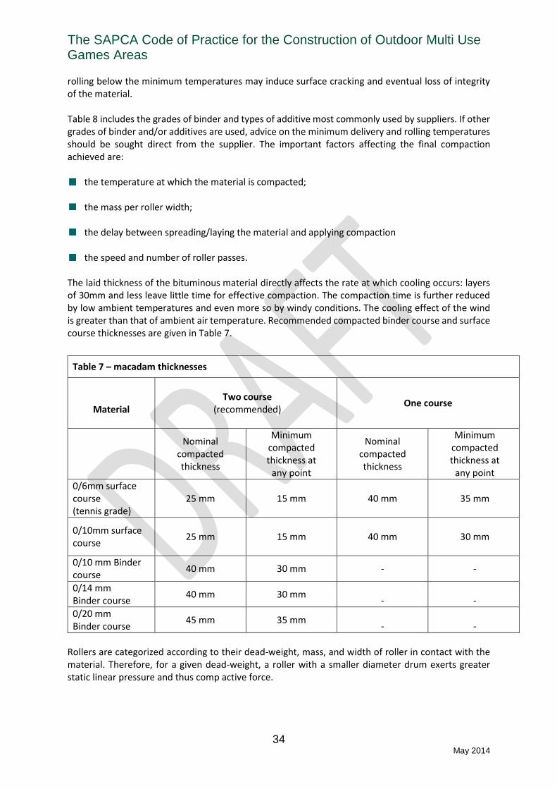
The SAPCA Code of Practice for the Construction of Outdoor Multi Use Games Areas
34 May 2014
rolling below the minimum temperatures may induce surface cracking and eventual loss of integrity of the material. Table 8 includes the grades of binder and types of additive most commonly used by suppliers. If other grades of binder and/or additives are used, advice on the minimum delivery and rolling temperatures should be sought direct from the supplier. The important factors affecting the final compaction achieved are:
the temperature at which the material is compacted;
the mass per roller width;
the delay between spreading/laying the material and applying compaction
the speed and number of roller passes. The laid thickness of the bituminous material directly affects the rate at which cooling occurs: layers of 30mm and less leave little time for effective compaction. The compaction time is further reduced by low ambient temperatures and even more so by windy conditions. The cooling effect of the wind is greater than that of ambient air temperature. Recommended compacted binder course and surface course thicknesses are given in Table 7.
Rollers are categorized according to their dead-weight, mass, and width of roller in contact with the material. Therefore, for a given dead-weight, a roller with a smaller diameter drum exerts greater static linear pressure and thus comp active force.
Table 7 – macadam thicknesses
Material
Two course
(recommended)
One course
Nominal compacted thickness
Minimum compacted thickness at
any point
Nominal compacted thickness
Minimum compacted thickness at
any point
0/6mm surface course (tennis grade)
25 mm 15 mm
40 mm
35 mm
0/10mm surface course
25 mm 15 mm
40 mm
30 mm
0/10 mm Binder course
40 mm 30 mm - -
0/14 mm Binder course
40 mm 30 mm -
-
0/20 mm Binder course
45 mm 35 mm -
-

The SAPCA Code of Practice for the Construction of Outdoor Multi Use Games Areas
35 May 2014
Table 8 – recommended macadam laying temperatures
Binder grade/ type of additive Minimum temperature
(within 30 minutes of arrival on site)
Minimum temperature (immediately prior
to rolling)
250/330 Pen 105oC 75oC
160/220 Pen 115oC 85oC
160/220 Pen + latex 140oC 100oC
160/220 Pen + polymer 140oC 100oC
100/150 Pen 135oC 95oC
It is possible to impose a greater compaction force using a vibratory mechanism. Vibratory rollers are commonly tandem rollers and apply dynamic compaction forces. The frequency and amplitude of the vibration determines the efficiency of compaction and vibratory rollers of a lower mass can achieve a higher compacted density than heavier dead weights. Vibratory rollers should only be employed on bituminous binder courses and not on thin layer surface courses, due to risk of aggregate fracture. The guiding principle for compaction is to use the heaviest roller that can be supported by the construction. Table 9 gives an indication of the number of compaction passes required by roller type, applying the minimum temperatures immediately prior to rolling, as stated in Table 7, to compact fully a bituminous layer of up to 50mm thickness.
Surface Texture Porous macadam surfaces should be laid to an even and consistent texture to ensure an optimum appearance and minimal variation in playing characteristics. Manufacturing and laying operations should be controlled in order to minimise textural variations. Some degree of textural variation is, however, inherent in certain materials and laying procedures used for tennis court surfacing, such as bitumen macadam. Such variations are acceptable providing that they are not so severe as to affect significantly the playing characteristics, porosity or strength of the surface, and providing that the appearance of the court is not unreasonably impaired.
Table 9 – number of compaction passes required by roller type
Roller mass Type Minimum number of
roller passes
600 - 1,000 Kg/m Single drum 12
600 - 1,000 Kg/m Twin drum vibratory 6
1,000 - 2,000 Kg/m Single drum 8
1,000 - 2,000 Kg/m Twin drum vibratory 4
Greater than 2,000 Kg/m Single drum 6
Greater than 2,000 Kg/m Twin drum vibratory 3

The SAPCA Code of Practice for the Construction of Outdoor Multi Use Games Areas
36 May 2014
Macadam bay joints Construction joints are inherent in most surfacing systems. They should, however, be neat and even and should not affect the bounce of the ball. Marks left by the roller during the laying of the surface may be visible, particularly in certain light conditions, but they should never be so severe either to deflect a ball in play, or to be detectable underfoot by a player. Initial settling down period
Macadam surfaces require some degree of extra care when used during the immediate post-construction phase. It is important for purchasers to be fully informed as to when the court may be first used and any precautions that may be necessary until the surface has fully "settled down". This is particularly important in the case of bitumen bound surfaces, which may be subject to some softening during hot weather.
2.9 Paint coatings for macadam MUGAs (types 1 and 2) Many macadam MUGAs are colour coated to increase their visual appeal. However, the choice of colour coating is critical if the MUGA is to have the level of performance, slip resistance, porosity and durability that a client may reasonably expect. Factors that need to be considered include:
the intensity of use – a court subjected to high usage will cause the coating to wear more
rapidly than a court used only occasionally;
the types of footwear that will be worn by players - the use of sports shoes with pronounced tread patterns will cause rapid abrasion of the colour coating;
the potential for contamination of the surface from debris (leaf litter, foot trafficking dirt etc. and atmospheric pollution) – the movement of grit will abrade the coating; and
the proximity of trees – sap from trees can cause premature failure of the coatings. Water-based acrylic paint The majority of painted porous tennis courts are colour-coated with water-based acrylic paint formulations, which typically contain acrylic resin, water, oxide pigments, mineral fillers and processing aids. The coatings are normally applied using industrial airless spraying equipment. Their tendency to soften in periods of prolonged exposure to moisture can mean, however that this type of coating will wear quite quickly with a loss of slip resistance.
Solvent-based polyurethane paint and polyurethane / acrylic blends These paints form a harder wearing and durable coating that are suited to areas of high use such as MUGAs. Due to the higher rigidity of the paint film there is an increased risk of cracking of the macadam surface due to the differential in the thermal expansion rates of macadam and the paint film. Therefore great care needs to be taken to ensure that the correct amount of paint is applied to the macadam.

The SAPCA Code of Practice for the Construction of Outdoor Multi Use Games Areas
37 May 2014
Macadam curing If a MUGA is painted before the bitumen incorporated in the macadam has been allowed to harden adequately, the paint will cure satisfactorily but during periods of hot weather the bitumen below will soften. Foot traffic will break away the hard paint film leaving a black smear, often in the shape of a twisting sole or heel. Newly laid bitumen has a glossy finish; as it cures, the top layer hardens and it looses its sheen. It is at this stage that the court is normally considered suitable for spraying. The time it takes for oxidation to occur will vary depending on the nature of the surface and the weather but it will normally take between two and three weeks in the summer and may take up to three months in the winter.
Preparation prior to painting The area to be coated with paint or binder should be free of oil and grease and should be swept or blown free of dirt, leaves, grit and debris immediately prior to painting. To minimise the affects of paint drift the edges of the court and perimeter fencing should be masked with sheeting, boarding or other suitable material for a height of around 1m, dependent on the prevailing wind at the time of spraying. The manufacturers of paints and binders will provide details of the types of protective clothing, facemasks, etc. that are recommended when using their products. If any doubt arises the advice of the manufacturer should be sought.
Weather conditions when painting Painting should only be undertaken in fine, dry, relatively still weather – this makes programming notoriously difficult for contractors and delays are a common occurrence. After being sprayed onto the macadam surface the paint dries to the stage where it is touch dry, and at this stage it starts its initial curing. This can take between one and twelve hours, depending on temperature, humidity and air movement. Air movement is by far the most important factor in controlling the curing time. Painting should only be undertaken when the temperature of the surface to be coated is above 5°C (40°F) and is likely to remain so for a minimum of six to seven hours. A paint film will actually cure at temperatures as low as 0°C, though it will take an unacceptably long time to cure at such low temperatures. It is important to remember that the temperature of the ground affects the curing of the paint and that it should be the ground temperature that is measured not the air temperature - many sunny autumn days have an air temperature above 10°C or 15°C whilst the ground temperature (and therefore the film temperature) remains at 2°C or 3°C. As a rule of thumb spraying is normally only undertaken during the period of British Summer Time.
Paint application rates The application of paint or binders is by airless spray technique. Pressures will depend on many factors but will typically be between 2,500 and 5,500 psi. The tip size should be carefully selected to ensure correct atomisation of the coating (28 thou. being typical) and the spray fan should be uniform with a feathered edge so that there are minimal discernible lines on the painted surface. Two coats of paint should be applied in different directions to ensure an even finish with no patches. Paint and binder coatings should be mixed according to the manufacturer’s instructions and applied at the recommended application rates. Some paints are supplied ready for spraying whilst others require dilution on site. It is essential that paints should be diluted at the rates specified by the manufacturer, as excessive dilution will cause premature failure of the paint film. When a binder has been applied it is important that the colour coating should be applied before the binder has dried fully, to ensure good bonding between the coatings.

The SAPCA Code of Practice for the Construction of Outdoor Multi Use Games Areas
38 May 2014
As a guide, typical application rates are detailed in Table 10. The ranges take into account the varying sizes of tennis and netball court areas. To allow the coating to cure fully, it is recommended that courts are left for at least three days, and ideally five, depending on the conditions after coating and before play commences. The contractor’s advice should always be sought and followed to ensure that damage to the coating does not occur.
Table 10 - coating applications
Product type New macadam court
(litres) *
Water-based acrylic paint 170 – 200
Acrylic / polyurethane blended paint 170 – 200
Water-based polyurethane paint 160 – 180
Solvent-based polyurethane paint 150 – 175
* The actual quantity of paint required will depend on the size of the court. The ranges details are based on the LTA ‘s minimum and recommended court sizes
2.10 Playing Lines One of the obvious limitations of a MUGA is the possible difficulty for players in identifying the relevant play lines, where there are many overlapping sets of lines on the same surface. For this reason it is unwise to include lines just for the sake of completeness, if the sport is not likely to be played very often. The problem is usually more pronounced for sports such as tennis, where it is very important that the lines should be quickly and clearly seen by the players. Playing lines can be painted on to most surfaces, but with synthetic turf they are usually either tufted in during manufacture or cut in when installing the surface. The choice of colours is also important, and advice should be taken on the most suitable combinations of colours for the sports to be included. As a rule of thumb, the most frequently used sport should be marked out in white, the second most played sport in yellow, followed by blue, and red. Where the rules of the sport do not detail tolerances for the accuracy of the markings the lines should be within 20mm of the specified dimension. Straight lines should not deviate by more than 10mm from a line joining their ends, nor include any sudden steps. All lines should be bright, straight and have a sharp, defined edge.
As lines form part of the playing area, they should also satisfy the slip resistance criteria for the court. It is for this reason that the use of aerosol paint cans for permanent lines is not recommended due to the low values of slip resistance usually achieved, and their poor durability. 2.11 Corrective/Remedial Action Some surfaces, most notably macadam, are extremely difficult to repair imperceptibly. A degree of reasonableness should therefore be applied when assessing minor areas of non-compliance for their effect on performance and suitability for purpose, and the appropriate extent of any remedial action. Where remedial works are required the repaired surface should match adjoining areas in colour, texture and levels and, except where invisible mending can be achieved, (e.g. some synthetic grass

The SAPCA Code of Practice for the Construction of Outdoor Multi Use Games Areas
39 May 2014
surfaces), should be replaced to the nearest play lines or construction joints. Joints should be neat, straight and unobtrusive. 2.12 Quality Control To ensure that all components used during the construction of a MUGA and that the entire construction meets the specified requirements a system of quality control should be established with the contractor. Checks on materials and workmanship should be carried out throughout the construction period. 2.12.1 Workmanship The quality of the workmanship should be checked at various ‘key’ stages during the construction process against the specification for the works. Such stages may include the following:
At completion of the formation, to check size, levels and gradients;
At completion of the construction of the drainage system, to ensure that all connections have been made and that the correct falls have been made in pipe work;
At completion of the installation of the sub-base, to check that the correct depth has been installed and that level tolerances have been met;
At completion of the base again to check that level and thickness requirements have been met;
At completion of the shockpad to check thickness (if required);
At completion of the surface to ensure consistency (and if required infill depth across the surface);
At completion of the line markings to check the evenness and quality.
2.12.2 Performance testing on completion The specification for any MUGA should include the specific sports performance requirements dictated by the sport to be played. These performance requirements are specified in a number of ways, either to sport’s governing body requirements or to British Standards. Appendix A details the applicable performance and construction characteristics schedules for the various surfacing and construction types. Where Performance Testing is required, they should be carried out by Independent accredited laboratories. A list of these can be provided by the relevant governing bodies or funding agency. Where such a list is not available the minimum criteria should be that the test laboratory is ISO 17025 accredited for the tests required. Details of suitable test laboratories may also be obtained from SAPCA. Performance testing should be carried out on the completed facility, it is recognised that some types of MUGA surfacing do not reach their normal playing performance until the surface has settled down requiring testing to be undertaken after a couple of month’s use. The purpose of these tests is to ensure that the completed facility meets the performance and construction requirements.
The SAPCA Code of Practice for the Construction of Outdoor Multi Use Games Areas
40 May 2014
2.13 Fittings and Equipment The sports equipment chosen to be installed needs to reflect the multi-use of the facility. Generally all equipment should be able to be removed to enable the range of sports to be played, although some fixed equipment may be possible if its location does not affect the use of the area for the other sports for which it was designed. These days there is a wide range of nets, posts, goals, division netting and rebound boards to choose from. Consideration should be given to the precise use of each facility, so that the change of usage from one sport to another can take place with the minimum of effort and inconvenience. Nets, posts and goals can be free-standing, and therefore easily moved, though it is important to make proper provision for their storage when not required, from the point of view of both safety and security. It is vital that great care should be taken to ensure the safe anchorage of all free-standing equipment.
Football goals (full size) should comply with BS EN 748.
Five-a-side or small-sided football metal goals should comply with BS 8462
Handball goals should comply with BS EN 749.
Hockey goals should comply with BS EN 750.
Netball goal posts should be supplied with protective post pads in accordance with AENA requirements.
Tennis posts and nets should comply with BS EN 1510.
Recessed sockets in the playing surface are quite usual for surfaces such as macadam and polymeric, though less practical for sand-filled synthetic grass. Whilst providing a convenient solution to fixing equipment the socket covers can be slippery and considered undesirable by sports such as netball. Also available are proprietary sports equipment systems, which offer high quality bespoke solutions, such as integrated surround fencing and a variety of goal units. Especially preferable are recessed goals for five-a-side football, in order that the goals should be flush with the rebound boards or walls.
Equipment storage
Mainstay portable sports equipment can be stored outdoors – it is designed to be exposed to the elements. Specialist non-personal equipment e.g. training cones, goals netting etc. are best kept in a secure facility or vandal resistant storage container close to the MUGA.
On facilities where football and its derivatives are likely to be played it is sensible to build into the perimeter fence suitably sized recesses to accommodate and anchor portable soccer goals. The design should ensure there is sufficient height clearance in the fence goal recess to prevent cranial and thoracic injury - largely caused by someone running towards the goals or keeping goal. The design should ensure it is easy to retrieve balls from the fence recesses and goal itself (goals may not even require netting for certain standards of play). Above all the ability to securely anchor the frame of the goals to prevent them toppling over is paramount.
The SAPCA Code of Practice for the Construction of Outdoor Multi Use Games Areas
41 May 2014
If goals are required to stand inside the perimeter fence line during play it is essential they are returned to storage recesses when the full pitch (or portions), are to be used. Beyond the play lines, run-offs are provided to ensure users can stop safely, so it is important to ensure that equipment is not stored in them. Where possible the design of the MUGA should allow for full size portable football and hockey goals to be relocated into fence design recesses, conveniently located behind the goal locations at each end zone of the facility. Such recesses should have secured posts of sufficient height (equivalent to the main perimeter fence height) with a high level permanent tensioned wire - to allow a netting to be pulled across to containment for seven-a-side football end zone utilisation of the main pitch, when the main pitch goals are retracted into their equipment recesses. 2.14 Surround Fencing SAPCA has produced a Code of Practice for the Construction and Maintenance of Fencing Systems for Sports Facilities. This document looks at many aspects for the choice of a fencing system and also lays down requirements for its construction and maintenance to which all SAPCA fencing contractors adhere. On MUGAs where site security is not a major concern and the primary use is tennis, chainlink fencing may be suitable. On all other types of MUGA weld mesh panels or rolls or rigid bar fencing is considered more appropriate due to their ability to withstand the repeat impacts from large balls; a good fencing contractor should be able to demonstrate a variety of options and advise on the advantages and disadvantages of each fencing system. All gate thresholds should be level or slightly ramped (i.e. not stepped) to avoid trip points and to allow disabled persons access. Gates should also be positioned so as not to create “tight” gathering or milling points, especially where pitch/games area team changeovers are scheduled. Divider netting and screening In order to maximise the use of larger MUGAs good quality division netting can be installed to split the playing area into separate, smaller areas of activity, as required. Care should be taken in the selection of the netting to ensure the safety of players at all times, avoiding, as far as possible, potential trip hazards. The greatest care should be taken if site screening or windbreak materials are to be hung on the surround fencing, to ensure that the design of the fencing is sufficiently robust. A heavy-duty surround system will normally be required for this purpose and provision (recesses) should be made to store the netting off the playing are when not in use. Ball rebound systems Where appropriate, particularly on MUGAs where five-a-side football is to be played, a rebound wall or board system should be installed. Rebound walls and boards can be constructed from a variety of materials and may be stained or painted in order to improve their aesthetic appearance. A number of companies now also offer rebound fencing. These are advantageous where user and site security issues are a concern as they allow viewing of the total area.

The SAPCA Code of Practice for the Construction of Outdoor Multi Use Games Areas
42 May 2014
2.15 Sports Lighting The inclusion of a sports lighting system in the construction of a MUGA is sometimes essential to ensure that the area is commercially viable; in fact some funding agencies stipulate minimum hours of use, which will mean that a lighting system is required. Because of the sensitive nature of sports lighting, planning authorities may impose restrictions which are not possible to meet or which will mean that the chosen location for a pitch build may not be possible. Very careful consideration therefore needs to be given during the design, planning and construction phases of a facility build in this respect. Specialist advice will be required to ensure that the design of a system meets the planning authority guidelines. Specialist sports lighting designers and contractors will need to adhere strictly to any conditions imposed by the planners. SAPCA is in the process of writing a Code of Practice for Sports Lighting, which will be published in 2013. Typical lighting performance levels for MUGAs are detailed in Table 11.
Table 11 - Typical MUGA lighting levels based on principal sports use
Sport
Illumination standards based on measurements taken after dark at ground level
Maintained average luminance Uniformity (Min/Ave)
Tennis, competitive Netball, Basketball, etc.
400 lux ≥ 0.7
Football, general sports training, causal play (all sports)
200 lux ≥ 0.7
Section 3 - Maintenance The maintenance of all types of sports surfacing systems is essential to ensure that the playing characteristics are kept at the appropriate level throughout their lives. Most manufacturers offer warranties of between 5 and 10 years, and many specifiers ask that warranties are performance based ensuring that there are specific measurable performance requirements that should be met through to the end of the warranty. It is essential therefore that the client ensures that the maintenance regime suggested by the contractor and manufacturer is rigorously adhered to. It is further recommended that the client keeps a log of all operations carried out on the facility, from general house keeping carried out by the owner to more specialist cleaning usually undertaken by outside contractors. A suitable log can be downloaded from the SAPCA website and used by clients providing they inform the installation contractor and / or manufacturer of the surface. As part of their contractual obligations under the Construction Design and Management Regulations, the contractor must supply the client with full details of the required maintenance for all parts of a facility. These details are contained in the maintenance manual which should be provided at completion of the works

The SAPCA Code of Practice for the Construction of Outdoor Multi Use Games Areas
43 May 2014
SAPCA has produced a Code of Practice for the Maintenance of all Synthetic Sports Surfaces and a Code of Practice for the Maintenance of all Tennis Courts, which describe in details the maintenance requirements of the various surfaces used on MUGAs. Most surfaces installed on MUGA’s are fully permeable, and hard-wearing, however to ensure that the surface continues to meet the specific performance requirements throughout its life a degree of maintenance is essential. This maintenance is of vital importance if the surface is to remain good to look at, consistent in play, permeable and long lasting. Indeed, the installers’ guarantee will usually be conditional on the recommended maintenance requirements being carried out with reasonable diligence. Maintenance procedures should designed to ensure that:
The playing surface is kept scrupulously clean;
The playing surface remains level and of consistent texture so that it gives a true and predictable game ;
The free drainage of surface water is maintained throughout the life of the MUGA;
The facility looks attractive and well-kept at all times;
Ensure that the specific performance requirements are met.

The SAPCA Code of Practice for the Construction of Outdoor Multi Use Games Areas
44 May 2014
Appendix A Performance and construction requirements for MUGAs, types 1 to 9
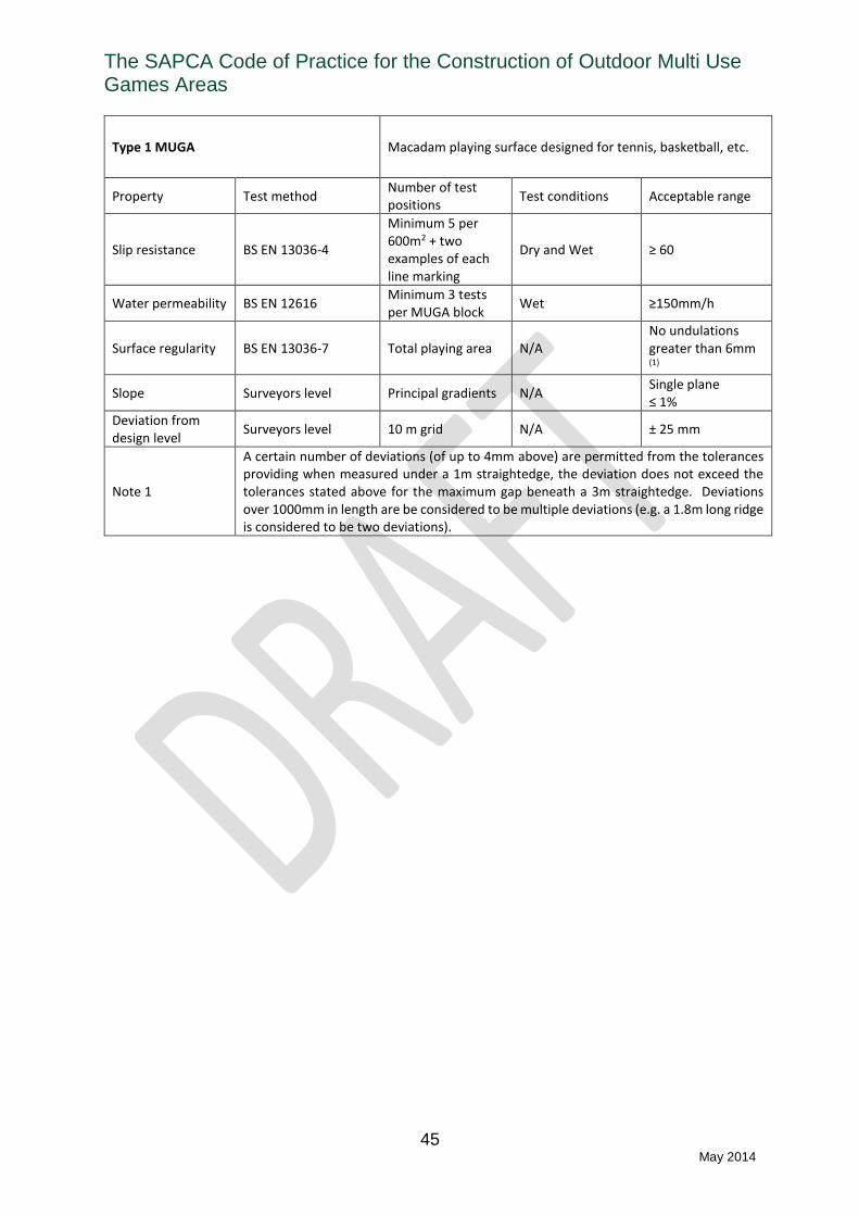
The SAPCA Code of Practice for the Construction of Outdoor Multi Use Games Areas
45 May 2014
Type 1 MUGA Macadam playing surface designed for tennis, basketball, etc.
Property Test method Number of test positions
Test conditions Acceptable range
Slip resistance BS EN 13036-4
Minimum 5 per 600m2 + two examples of each line marking
Dry and Wet ≥ 60
Water permeability BS EN 12616 Minimum 3 tests per MUGA block
Wet ≥150mm/h
Surface regularity BS EN 13036-7 Total playing area N/A No undulations greater than 6mm (1)
Slope Surveyors level Principal gradients N/A Single plane ≤ 1%
Deviation from design level
Surveyors level 10 m grid N/A ± 25 mm
Note 1
A certain number of deviations (of up to 4mm above) are permitted from the tolerances providing when measured under a 1m straightedge, the deviation does not exceed the tolerances stated above for the maximum gap beneath a 3m straightedge. Deviations over 1000mm in length are be considered to be multiple deviations (e.g. a 1.8m long ridge is considered to be two deviations).

The SAPCA Code of Practice for the Construction of Outdoor Multi Use Games Areas
46 May 2014
Type 2 MUGA Macadam playing surface designed for Netball
Property Test method Number of test positions
Test conditions Acceptable range
Slip resistance BS EN 13036-4
Minimum 5 per 600m2 + two examples of each line marking
Dry and Wet ≥ 75
Water permeability BS EN 12616 Minimum 3 tests per MUGA block
Wet ≥150mm/h
Surface regularity BS EN 13036-7 Total playing area N/A No undulations greater than 6mm (1)
Slope Surveyors level Principal gradients N/A Single plane ≤ 1%
Deviation from design level
Surveyors level 10 m grid N/A ± 25 mm
Note 1
A certain number of deviations (of up to 4mm) are permitted from the tolerances providing when measured under a 1m straightedge, the deviation does not exceed the tolerances stated above for the maximum gap beneath a 3m straightedge. Deviations over 1000mm in length are be considered to be multiple deviations (e.g. a 1.8m long ridge is considered to be two deviations).

The SAPCA Code of Practice for the Construction of Outdoor Multi Use Games Areas
47 May 2014
Type 3 MUGA Polymeric playing surface designed for netball, tennis, basketball, etc.
Principle materials standard BS EN 14877
Property Test method Number of test positions
Test conditions Acceptable range
Slip resistance BS EN 13036-4
Minimum 5 per 600m2 + two examples of each line marking
Dry and Wet ≥ 75
Basketball rebound BS EN 12235 5 Prevailing site conditions
≥ 80%
Tennis ball rebound
BS EN 12235 5 Prevailing site conditions
≥ 80%
Shock absorption BS EN 14808 5 Prevailing site conditions in range 5°C - 30°C
25% - 44%
Vertical deformation
BS EN 14809 5 Prevailing site conditions in range 5°C - 30°C
≤ 6.0 mm
Water permeability BS EN 12616 Minimum 3 tests per MUGA block
Wet ≥150 mm/h
Thickness BS EN 1569 5 N/A ≥ 90% of manufacturer’s declaration
Tensile strength BS EN 12330 See note 1 - ≥ 0.4 MPa
Surface regularity BS EN 13036-7 Total playing area N/A No undulations greater than 6mm (2)
Slope Surveyors level Principal gradients N/A Single plane ≤ 1%
Deviation from design level
Surveyors level 10 m grid N/A ± 25 mm
Note 1 During each day of installation a 300 mm x 300 mm sample tray representing the installed surface shall be prepared and left on site for at least 48 hours to cure before being sent to the test laboratory for testing.
Note 2
A certain number of deviations (of up to 4mm) are permitted from the tolerances providing when measured under a 1m straightedge, the deviation does not exceed the tolerances stated above for the maximum gap beneath a 3m straightedge. Deviations over 1000mm in length are be considered to be multiple deviations (e.g. a 1.8m long ridge is considered to be two deviations).
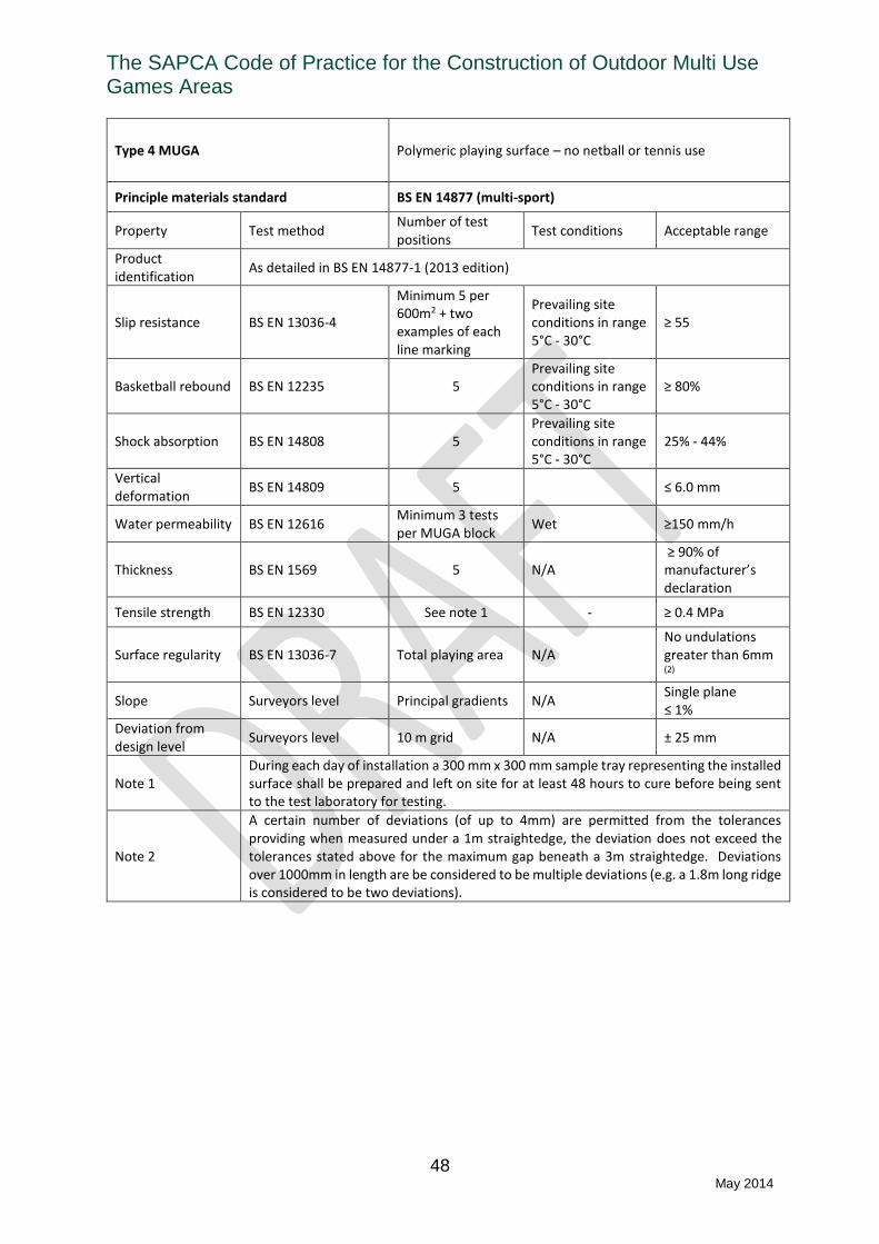
The SAPCA Code of Practice for the Construction of Outdoor Multi Use Games Areas
48 May 2014
Type 4 MUGA Polymeric playing surface – no netball or tennis use
Principle materials standard BS EN 14877 (multi-sport)
Property Test method Number of test positions
Test conditions Acceptable range
Product identification
As detailed in BS EN 14877-1 (2013 edition)
Slip resistance BS EN 13036-4
Minimum 5 per 600m2 + two examples of each line marking
Prevailing site conditions in range 5°C - 30°C
≥ 55
Basketball rebound BS EN 12235 5 Prevailing site conditions in range 5°C - 30°C
≥ 80%
Shock absorption BS EN 14808 5 Prevailing site conditions in range 5°C - 30°C
25% - 44%
Vertical deformation
BS EN 14809 5 ≤ 6.0 mm
Water permeability BS EN 12616 Minimum 3 tests per MUGA block
Wet ≥150 mm/h
Thickness BS EN 1569 5 N/A ≥ 90% of manufacturer’s declaration
Tensile strength BS EN 12330 See note 1 - ≥ 0.4 MPa
Surface regularity BS EN 13036-7 Total playing area N/A No undulations greater than 6mm (2)
Slope Surveyors level Principal gradients N/A Single plane ≤ 1%
Deviation from design level
Surveyors level 10 m grid N/A ± 25 mm
Note 1 During each day of installation a 300 mm x 300 mm sample tray representing the installed surface shall be prepared and left on site for at least 48 hours to cure before being sent to the test laboratory for testing.
Note 2
A certain number of deviations (of up to 4mm) are permitted from the tolerances providing when measured under a 1m straightedge, the deviation does not exceed the tolerances stated above for the maximum gap beneath a 3m straightedge. Deviations over 1000mm in length are be considered to be multiple deviations (e.g. a 1.8m long ridge is considered to be two deviations).
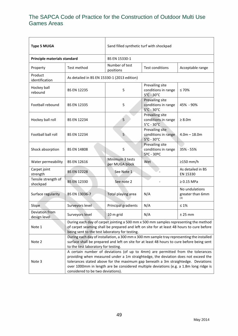
The SAPCA Code of Practice for the Construction of Outdoor Multi Use Games Areas
49 May 2014
Type 5 MUGA Sand filled synthetic turf with shockpad
Principle materials standard BS EN 15330-1
Property Test method Number of test positions
Test conditions Acceptable range
Product identification
As detailed in BS EN 15330-1 (2013 edition)
Hockey ball rebound
BS EN 12235 5 Prevailing site conditions in range 5°C - 30°C
≤ 70%
Football rebound BS EN 12335 5 Prevailing site conditions in range 5°C - 30°C
45% - 90%
Hockey ball roll BS EN 12234 5 Prevailing site conditions in range 5°C - 30°C
≥ 8.0m
Football ball roll BS EN 12234 5 Prevailing site conditions in range 5°C - 30°C
4.0m – 18.0m
Shock absorption BS EN 14808 5 Prevailing site conditions in range 5ºC - 30ºC
35% - 55%
Water permeability BS EN 12616 Minimum 3 tests per MUGA block
Wet ≥150 mm/h
Carpet joint strength
BS EN 12228 See Note 1 - As detailed in BS EN 15330
Tensile strength of shockpad
BS EN 12330 See note 2 - ≥ 0.15 MPa
Surface regularity BS EN 13036-7 Total playing area N/A No undulations greater than 6mm (3)
Slope Surveyors level Principal gradients N/A ≤ 1%
Deviation from design level
Surveyors level 10 m grid N/A ± 25 mm
Note 1 During each day of carpet jointing a 500 mm x 500 mm samples representing the method of carpet seaming shall be prepared and left on site for at least 48 hours to cure before being sent to the test laboratory for testing.
Note 2 During each day of installation, a 300 mm x 300 mm sample tray representing the installed surface shall be prepared and left on site for at least 48 hours to cure before being sent to the test laboratory for testing.
Note 3
A certain number of deviations (of up to 4mm) are permitted from the tolerances providing when measured under a 1m straightedge, the deviation does not exceed the tolerances stated above for the maximum gap beneath a 3m straightedge. Deviations over 1000mm in length are be considered multiple deviations (e.g. a 1.8m long ridge is considered to be two deviations).

The SAPCA Code of Practice for the Construction of Outdoor Multi Use Games Areas
50 May 2014
Type 6 MUGA Sand filled synthetic turf without shockpad – principle use tennis
Principle materials standard BS EN 15330-1
Property Test method Number of test positions
Test conditions Acceptable range
Product identification
As detailed in BS EN 15330-1 (2013 edition)
Tennis ball rebound
BS EN 12235 3 per tennis court Prevailing site conditions in range 5°C - 30°C
≥ 80%
Tennis Surface Pace
BS EN 13865 3 per tennis court Prevailing site conditions in range 5°C - 30°C
Same classification as manufacturer’s declaration
Shock absorption BS EN 14808 2 per tennis court Prevailing site conditions in range 5ºC - 30ºC
≥ 90% of manufacturer’s declaration
Water permeability BS EN 12616 Minimum 3 tests per court block
Wet ≥150 mm/h
Carpet joint strength
BS EN 12228 See Note 1 - As detailed in BS EN 15330
Surface regularity BS EN 13036-7 Total playing area N/A No undulations greater than 6mm (2)
Slope Surveyors level Principal gradients N/A Single plane ≤ 1%
Deviation from design level
Surveyors level 10 m grid N/A ± 25 mm
Note 1 During each day of carpet jointing a 500 mm x 500 mm samples representing the method of carpet seaming shall be prepared and left on site for at least 48 hours to cure before being sent to the test laboratory for testing.
Note 2
A certain number of deviations (of up to 4mm) are permitted from the tolerances providing when measured under a 1m straightedge, the deviation does not exceed the tolerances stated above for the maximum gap beneath a 3m straightedge. Deviations over 1000mm in length are be considered to be multiple deviations (e.g. a 1.8m long ridge is considered to be two deviations).
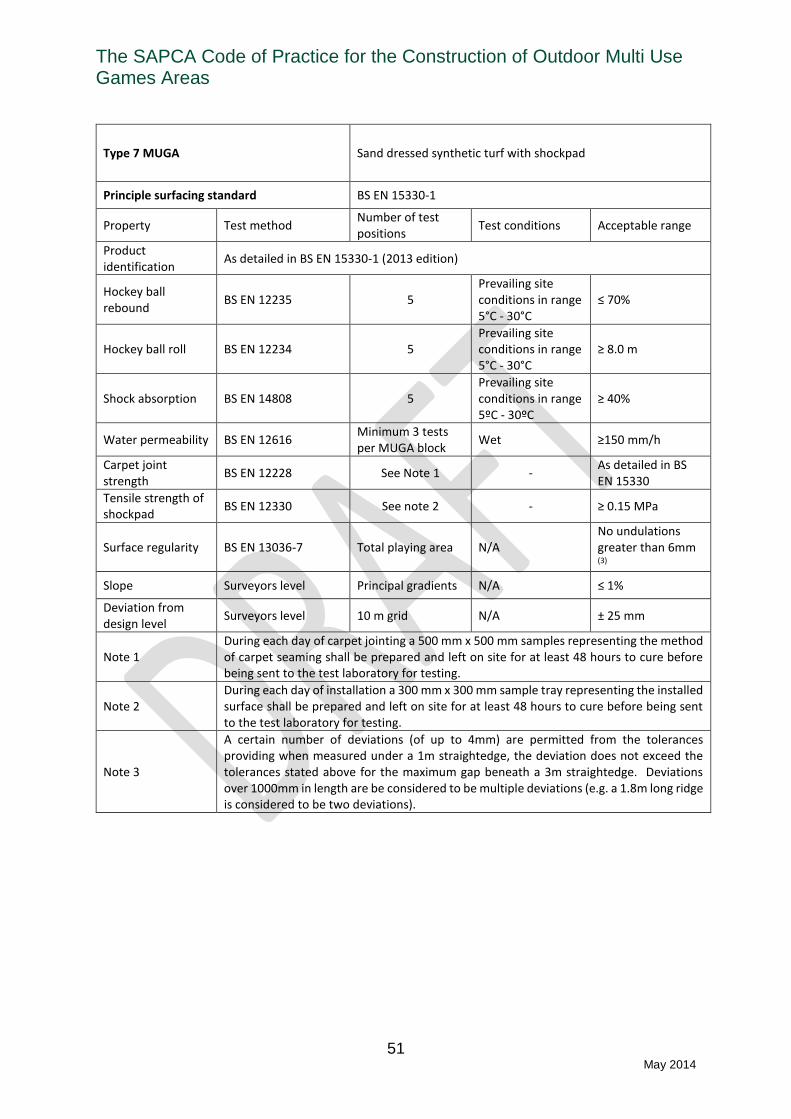
The SAPCA Code of Practice for the Construction of Outdoor Multi Use Games Areas
51 May 2014
Type 7 MUGA Sand dressed synthetic turf with shockpad
Principle surfacing standard BS EN 15330-1
Property Test method Number of test positions
Test conditions Acceptable range
Product identification
As detailed in BS EN 15330-1 (2013 edition)
Hockey ball rebound
BS EN 12235 5 Prevailing site conditions in range 5°C - 30°C
≤ 70%
Hockey ball roll BS EN 12234 5 Prevailing site conditions in range 5°C - 30°C
≥ 8.0 m
Shock absorption BS EN 14808 5 Prevailing site conditions in range 5ºC - 30ºC
≥ 40%
Water permeability BS EN 12616 Minimum 3 tests per MUGA block
Wet ≥150 mm/h
Carpet joint strength
BS EN 12228 See Note 1 - As detailed in BS EN 15330
Tensile strength of shockpad
BS EN 12330 See note 2 - ≥ 0.15 MPa
Surface regularity BS EN 13036-7 Total playing area N/A No undulations greater than 6mm (3)
Slope Surveyors level Principal gradients N/A ≤ 1%
Deviation from design level
Surveyors level 10 m grid N/A ± 25 mm
Note 1 During each day of carpet jointing a 500 mm x 500 mm samples representing the method of carpet seaming shall be prepared and left on site for at least 48 hours to cure before being sent to the test laboratory for testing.
Note 2 During each day of installation a 300 mm x 300 mm sample tray representing the installed surface shall be prepared and left on site for at least 48 hours to cure before being sent to the test laboratory for testing.
Note 3
A certain number of deviations (of up to 4mm) are permitted from the tolerances providing when measured under a 1m straightedge, the deviation does not exceed the tolerances stated above for the maximum gap beneath a 3m straightedge. Deviations over 1000mm in length are be considered to be multiple deviations (e.g. a 1.8m long ridge is considered to be two deviations).

The SAPCA Code of Practice for the Construction of Outdoor Multi Use Games Areas
52 May 2014
Type 8 MUGA Long pile synthetic turf
Principle materials standard BS EN 15330-1
Property Test method Number of test positions
Test conditions Acceptable range
Football rebound BS EN 12335 5 Prevailing site conditions in range 5°C - 30°C
45% - 75%
Football ball roll BS EN 12234 5 Prevailing site conditions in range 5°C - 30°C
≤ 10.0m
Shock absorption BS EN 14808 5 Prevailing site conditions in range 5ºC - 30ºC
55% - 70%
Vertical deformation
BS EN 14809 5 Prevailing site conditions in range 5ºC - 30ºC
4mm – 9mm
Head Injury Criteria (2)
BS EN 1177 / IRB Reg. 22
5 Prevailing site conditions in range 5ºC - 30ºC
≥ 1.0m (3)
Water permeability BS EN 12616 Minimum 3 tests per MUGA block
Wet ≥150 mm/h
Carpet joint strength
BS EN 12228 See Note 4 - As detailed in BS EN 15330-1
Tensile strength of shockpad
BS EN 12330 See note 5 - ≥ 0.15 MPa
Surface regularity BS EN 13036-7 Total playing area N/A No undulations greater than 10 mm (6)
Slope Surveyors level Principal gradients N/A ≤ 1%
Deviation from design level
Surveyors level 10 m grid N/A ± 25 mm
Note 1 When site conditions permit
Note 2 Only necessary when contact rugby training is to take place on the MUGA
Note 3 IRB Regulation 22 requires any form of competitive rugby played on synthetic turf to take place on an IRB certified field
Note 4 During each day of carpet jointing a 500 mm x 500 mm samples representing the method of carpet seaming shall be prepared and left on site for at least 48 hours to cure before being sent to the test laboratory for testing.
Note 5 During each day of installation a 300 mm x 300 mm sample tray representing the installed surface shall be prepared and left on site for at least 48 hours to cure before being sent to the test laboratory for testing.
Note 6
A certain number of deviations (of up to 4mm) are permitted from the tolerances providing when measured under a 1m straightedge, the deviation does not exceed the tolerances stated above for the maximum gap beneath a 3m straightedge. Deviations over 1000mm in length are be considered to be multiple deviations (e.g. a 1.8m long ridge is considered to be two deviations).

The SAPCA Code of Practice for the Construction of Outdoor Multi Use Games Areas
53 May 2014
Type 9 MUGA Needle punch surface with shockpad
Principle surfacing standard BS EN 15330-2
Property Test method Number of test positions
Test conditions Acceptable range
Product identification
As detailed in BS EN 15330-2
Hockey ball rebound
BS EN 12235 5 Prevailing site conditions in range 5°C - 30°C
≤ 70%
Football rebound BS EN 12335 5 Prevailing site conditions in range 5°C - 30°C
45% - 90%
Hockey ball roll BS EN 12234 5 Prevailing site conditions in range 5°C - 30°C
5.0m – 18.0m
Football ball roll BS EN 12234 5 Prevailing site conditions in range 5°C - 30°C
4m – 18.0m
Shock absorption BS EN 14808 5 Prevailing site conditions in range 5ºC - 30ºC
35% - 55%
Water permeability BS EN 12616 Minimum 3 tests per MUGA block
Wet ≥150 mm/h
Carpet joint strength
BS EN 12228 See Note 1 - ≥ 25N/100mm
Tensile strength of shockpad
BS EN 12330 See note 2 - ≥ 0.15 MPa
Surface regularity BS EN 13036-7 Total playing area N/A No undulations greater than 6mm (3)
Slope Surveyors level Principal gradients N/A ≤ 1%
Deviation from design level
Surveyors level 10 m grid N/A ± 25 mm
Note 1 During each day of carpet jointing a 500 mm x 500 mm samples representing the method of carpet seaming shall be prepared and left on site for at least 48 hours to cure before being sent to the test laboratory for testing.
Note 2 During each day of installation a 300 mm x 300 mm sample tray representing the installed surface shall be prepared and left on site for at least 48 hours to cure before being sent to the test laboratory for testing.
Note 3
A certain number of deviations (of up to 4mm) are permitted from the tolerances providing when measured under a 1m straightedge, the deviation does not exceed the tolerances stated above for the maximum gap beneath a 3m straightedge. Deviations over 1000mm in length are be considered to be multiple deviations (e.g. a 1.8m long ridge is considered to be two deviations).
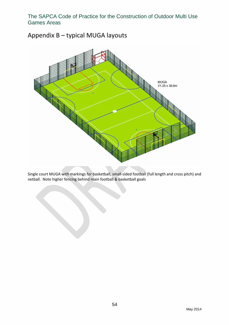
The SAPCA Code of Practice for the Construction of Outdoor Multi Use Games Areas
54 May 2014
Appendix B – typical MUGA layouts
Single court MUGA with markings for basketball, small-sided football (full length and cross pitch) and netball. Note higher fencing behind main football & basketball goals

The SAPCA Code of Practice for the Construction of Outdoor Multi Use Games Areas
55 May 2014
Large synthetic turf / needle punch playing surface with markings for small-sided football. Note recesses for football goal storage, robust perimeter fencing to withstand repeated impacts of footballs, double gates for vehicle access and single gate for pedestrian access / ball retrieval

The SAPCA Code of Practice for the Construction of Outdoor Multi Use Games Areas
56 May 2014
Double court with markings for small-sided football, tennis (x2) and provision of basketball goals. Netball could also be provided if required. Note use of colours to distinguish central court; whilst acceptable at a recreational level some sports may find this distracting in a formal competitive environment (e.g. league match play)

The SAPCA Code of Practice for the Construction of Outdoor Multi Use Games Areas
57 May 2014
Appendix C – typical design criteria of MUGA base constructions
Definitions Formation – the prepared ground on which the MUGA sub-base is laid
Construction stage Property Test method Requirement
Formation
Compaction
Dynamic Cone Penetrometer or California Bearing Ratio Three measurements for initial 2,000 m2 + one per additional 1000m2
CBR ≥ 5% (1)
Deviation from design level
Surveyors level on 10m grid(2)
± 25 mm
Drains
Gradient Surveys level Constant fall ≥ 1:200
Backfill permeability BS EN 12616 300 mm/h
Drain pipe cover - ≥ 150mm
Lateral spacing - Within 0.5m of design spacing
Sub-base
Mean compacted aggregate depth
See Note 2 Within 10% or 20mm of design depth, whichever is greater
Aggregate compaction Light weight deflectometer (Prima or similar)
Target value ≥ 60 MPa
Minimum value
≥ 40 MPa
Regularity BS EN 13036-7 No undulations greater than 15 mm
Aggregate permeability BS EN 12616 300 mm/h
Macadam layer(s) Thickness See Note 2
Single coarse ≥ 40 mm
Two coarse ≥ 65mm
Regularity BS EN 13036-7 As specified for playing surface
Note 1 Where ground conditions do not allow adequate compaction of the formation the use of stabilisation techniques such as Geo-grids, soil stabilisation, etc., should be used, as agreed with the Employer
Note 2 By taking spot levels following each stage of construction, the depth of the overlying layer may be calculated.