sankar polytechnic college …spc.edu.in/public/uploads/new ece m.pdf · unit – iv amplifiers and...
TRANSCRIPT
SANKAR POLYTECHNIC COLLEGE (AUTONOMOUS)
SANKAR NAGAR
DIPLOMA IN ELECTRONICS AND COMMUNICATION
ENGINEERING
M-SCHEME (Full Time)
II and III year
2016 onwards
DIPLOMA IN ELECTRONICS AND COMMUNICATION ENGINEERING

CURRICULUM OUTLINE Diploma in Electronics and Communication Engineering (Full Time)
III Semester
IV Semester
* Common to all branches
Subject Code
Subject Hours Per Week
Theory Hours
Tutorial / Drawing
Lab Hours
Total Hours
M431 Electronic Devices and Circuits 5 1 - 6
M432 Digital Electronics 5 1 - 6
M433 Electrical Circuits and Instrumentation
5 1 - 6
M434 Electronic Devices and Circuits Lab
- - 4 4
M435 Digital Electronics Lab - - 4 4
M436 Electrical Circuits and Instrumentation Lab
- - 4 4
M437 Computer Application Lab - - 4 4
Seminar 1 1
Total 35
Subject Code
Subject Hours Per Week
Theory Hours
Tutorial / Drawing
Lab Hours
Total Hours
M441 Communication Engineering 5 1 - 6
M442 Microprocessors 5 1 - 6
M443 Linear Integrated Circuits 5 1 - 6
M444 Programmable Logic Controller 4 - - 4
M445 Microprocessors Lab - - 4 4
M446 Linear Integrated Circuits Lab - - 4 4
M447 Life And Employability Skill Lab*
- - 4 4
Seminar 1 1
Total 35
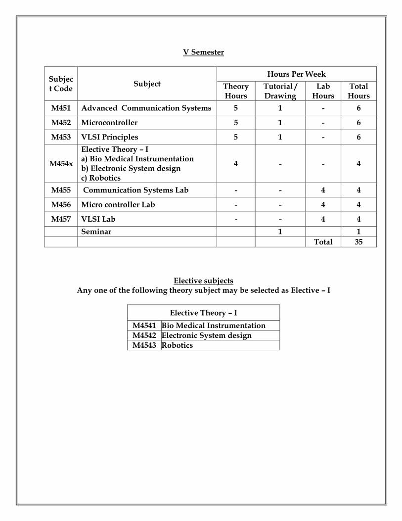
V Semester
Subject Code
Subject Hours Per Week
Theory Hours
Tutorial / Drawing
Lab Hours
Total Hours
M451 Advanced Communication Systems 5 1 - 6
M452 Microcontroller 5 1 - 6
M453 VLSI Principles 5 1 - 6
M454x
Elective Theory – I a) Bio Medical Instrumentation b) Electronic System design c) Robotics
4 - - 4
M455 Communication Systems Lab - - 4 4
M456 Micro controller Lab - - 4 4
M457 VLSI Lab - - 4 4
Seminar 1 1
Total 35
Elective subjects Any one of the following theory subject may be selected as Elective – I
Elective Theory – I
M4541 Bio Medical Instrumentation
M4542 Electronic System design
M4543 Robotics

VI Semester
Elective subjects Any one of the following theory subject with the corresponding Lab may be selected as
Elective – II
Elective Theory – II Elective Lab – II
M4631 Data Communication M4661 Robotics Lab
M4632 C Programming M4662 C Programming Lab
M4633 Computer Hardware and Network M4663
Computer Hardware and Test Engineering Lab
Subject Code
Subject Hours Per Week
Theory Hours
Tutorial / Drawing
Lab Hours
Total Hours
M461 Industrial Electronics 5 1 - 6
M462 Embedded System 5 1 - 6
M463x
Elective Theory – II a) Data Communication b) C Programming c) Computer Hardware and Network
5 1 - 6
M464 Embedded System Lab - - 4 4
M465 Industrial Electronics Lab - - 4 4
M466x
Elective Lab a) Robotics Lab b) C Programming Lab c) Computer Hardware and Test Engineering Lab
- - 4 4
M467 Project Work - - 4 4
Seminar 1 1
Total 35

SCHEME OF EXAMINATION
ELECTRONICS AND COMMUNICATION ENGINEERIING
THIRD SEMESTER
Sl.
No Subject
End Examination Marks
Internal
Marks
End
Examinations
Total
Marks
Minimum
for Pass
Duration of
Exam Hours
M431 Electronic Devices
and Circuits 25 75 100 40 3
M432 Digital Electronics 25 75 100 40 3
M433 Electrical Circuits
and Instrumentation 25 75 100 40 3
M434 Electronic Devices
and Circuits Lab 25 75 100 50 3
M435 Digital Electronics
Lab 25 75 100 50 3
M436
Electrical Circuits
and Instrumentation
Lab
25 75 100 50 3
M437 Computer
Application Lab 25 75 100 50 3
Total 175 525 700

FOURTH SEMESTER
Sl.
No Subject
End Examination Marks
Internal
Marks
End
Examination
Total
Marks
Minimum
for Pass Duration of
Exam Hours
M441 Communication
Engineering 25 75 100 40 3
M442 Microprocessors 25 75 100 40 3
M443 Linear Integrated
Circuits 25 75 100 40 3
M444 Programmable
Logic Controller 25 75 100 40 3
M445 Microprocessors
Lab 25 75 100 50 3
M446 Linear Integrated
CircuitsLab 25 75 100 50 3
M447
Life And
Employability Skill
Lab
25 75 100 50 3
Total 175 525 700
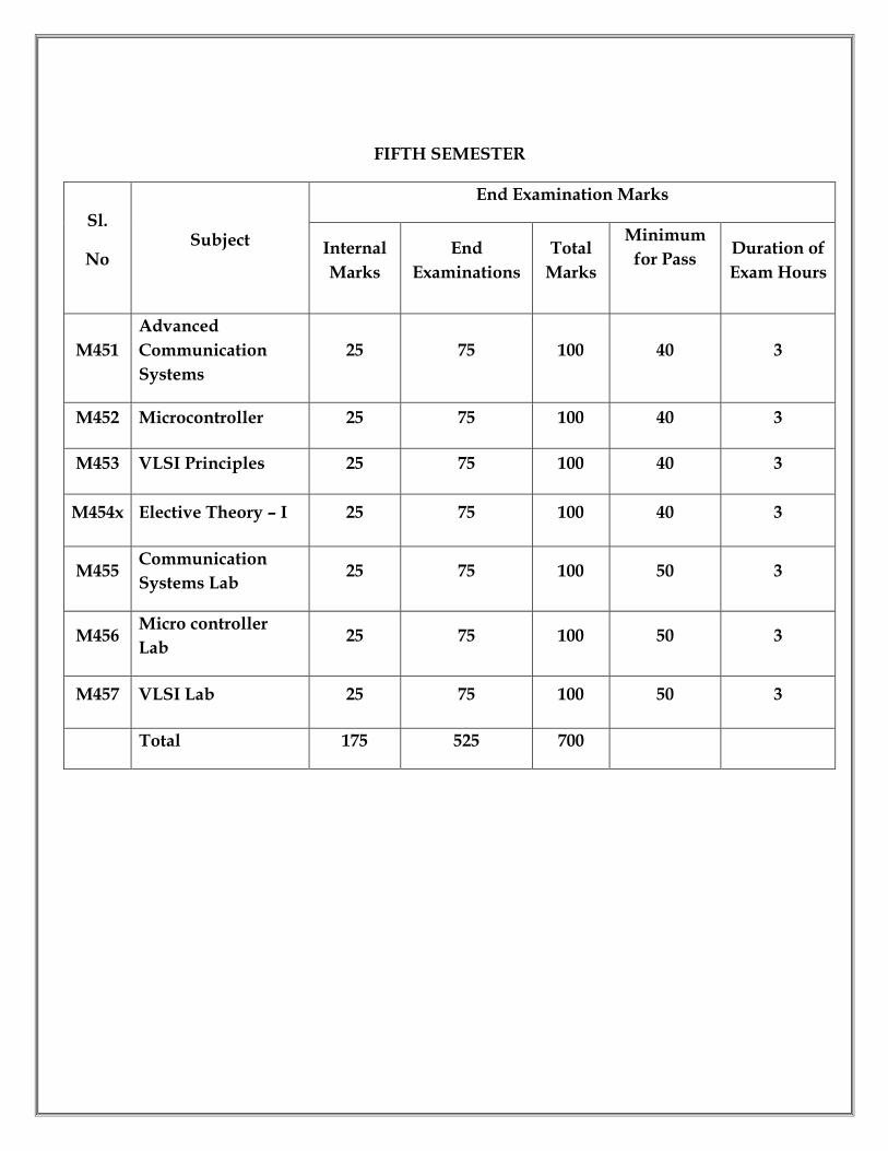
FIFTH SEMESTER
Sl.
No Subject
End Examination Marks
Internal
Marks
End
Examinations
Total
Marks
Minimum
for Pass Duration of
Exam Hours
M451
Advanced
Communication
Systems
25 75 100 40 3
M452 Microcontroller 25 75 100 40 3
M453 VLSI Principles 25 75 100 40 3
M454x Elective Theory – I 25 75 100 40 3
M455 Communication
Systems Lab 25 75 100 50 3
M456 Micro controller
Lab 25 75 100 50 3
M457 VLSI Lab 25 75 100 50 3
Total 175 525 700
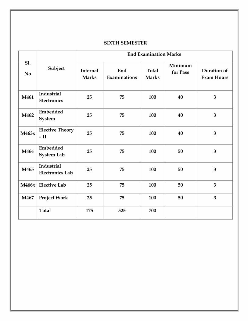
SIXTH SEMESTER
Sl.
No Subject
End Examination Marks
Internal
Marks
End
Examinations
Total
Marks
Minimum
for Pass Duration of
Exam Hours
M461 Industrial
Electronics 25 75 100 40 3
M462 Embedded
System 25 75 100 40 3
M463x Elective Theory
– II 25 75 100 40 3
M464 Embedded
System Lab 25 75 100 50 3
M465 Industrial
Electronics Lab 25 75 100 50 3
M466x Elective Lab 25 75 100 50 3
M467 Project Work 25 75 100 50 3
Total 175 525 700

M SCHEME (Implemented from the Academic year 2015- 2016 onwards)
Course Name: Electronics and Communication Engineering
Subject Code: M 431
Semester: III
Subject Title: ELECTRONIC DEVICES AND CIRCUITS
TEACHING AND SCHEME OF EXAMINATION:
Number of Weeks/ Semester: 15 Weeks
Subject
Instruction Examination
Hrs/
week
Hrs/
Sem
Internal
Assessment
End
Examination Total
Dura
tion
Electronic Devices And
Circuits 6 90 25 75 100 3 Hrs
Topics and allocation of hours
Unit Topic Time (Hrs)
I Semiconductor and diodes 15
II Bipolar and unipolar Transistor 16
III Power and Opto devices 14
IV Amplifiers and Voltage regulators 15
V Oscillators and wave shaping circuits 15
Revision and Test 15
Total 90
RATIONALE: Every Electronics Engineer should have sound knowledge about the components used in Electronics Industry. This is vital in R&D Department for chip level troubleshooting. To meet the industrial needs, diploma holders must be taught about the most fundamental subject, Electronic devices and Circuits. By studying this subject, they will be skilled in handling all types of electronic devices and able to apply the skill in electronics system. OBJECTIVES: On completion of the following units of syllabus contents, the students must be able to:
Study the working principle of PN junction diode and transistor
Understand the working principle of different types of rectifiers, different transistor configurations and differentiate various types of amplifiers
Study the performance of special devices like UJT, FET
Study the performance of different transistor oscillators
Study the performance of SCR, DIAC, and TRIAC
Study the performance and types of MOSFET
Study the performance of Power Amplifier
Study the different modes of operations of MOSFET
Know the construction and working principle of optoelectronic devices
Study the performance of solar cell with principle and applications
Explain the concept of wave shaping circuits
Study the working principle of clippers and clampers
M– 431 ELECTRONIC DEVICES AND CIRCUITS
Unit – I Semiconductor and Diodes: Resistors: Types of resistor –Fixed (carbon type construction only)–Variable –POT – Rheostat – Preset – Colour coding - Tolerance of resistors Semi conductor Theory: Atomic structure of silicon and germanium – energy level and energy band – classification based on energy band diagram –electron hole pair generation – intrinsicand extrinsic semiconductors – majority and minority carriers. PN Junction Diode: PN Junction diode – Forward and Reverse bias characteristics – Specifications Zener diode: Construction & working principle – Characteristics – Zener break down – Avalanche break down. Rectifier: Introduction – Classification of Rectifiers – Half Wave Rectifier – Full Wave Rectifier – Bridge Rectifier – Definition and values for Efficiency and Ripple factor (Only Definition and No mathematical derivations)–Comparison - Applications – Filters – C, LC and PI Filters. Unit – II Bipolar and unipolar Transistor Transistor: NPN and PNP transistor – operation –CB, CE, CC Configurations – Characteristics – cut off and saturation – Comparison between three configurations in terms of input impedance, output impedance, current gain, voltage gain–Transistor as a switch. Field Effect Transistor: Construction – Working principle of FET – Difference between FET and BJT – Characteristics of FET. MOSFET: Construction and Characteristics (N channel depletion and enhancement modes only)– Comparison between D and E MOSFET –MOSFET as a Switch UJT:
Construction – Equivalent circuit – Operation – characteristics –UJT as relaxation oscillator. Unit – III Power and Opto devices SCR: Introduction – Working – Two transistor analogy of SCR – VI characteristics – SCR as a Switch, Controlled rectifier. DIAC: Construction – Working – Characteristics – Diac as bi–directional switch. TRIAC: Basic working principle – Characteristics – Speed control of fan using Diac and Triac Opto Devices: LDR, LED, 7 segment LED, LCD, Opto coupler, Opto interrupter – Laser diode(simple treatment) –Solar cell – Photo diode – Photo transistor – IR LED and IR Sensor. Unit – IV Amplifiers and Voltage regulators Regulator: Zener diode voltage regulator – Transistor regulators – Series and shunt Transistor biasing: Need for Biasing – Fixed bias, Collector to base bias, Self bias Amplifiers: Small signal amplifier: Transistor Amplifier (Common Emitter) –frequency response and bandwidth of amplifier - RC coupled amplifier – Types of feedback–Negative feedback – Basic concept, advantages –Comparison between negative and positive feedback - Emitter follower and its application–Darlington pair– Common source amplifier. Large signal amplifier:classification of power amplifiers – Working principle of Class B push pull amplifier Unit –V Oscillators and wave shaping circuits Oscillator: Classifications – Condition for Oscillation (Barkhausencritierion) – General form of LC Oscillator – Hartley Oscillator – Colpitts Oscillator – RC Phase shift Oscillator – Crystal oscillator Wave shapping circuits: Diode Clipper and Clamper, Voltage Doubler –Astable, Monostable and BistableMultivibrators using Transistor. Reference Books: 1. Electronic Devices and Circuits by Boylstead, Tata McGraw Publication 2. Principle of Electronics by V.K.Mehta, S.Chand& Company ltd. 3. Electronics Devices & Circuits by Salivahanan, N.Suresh Kumar, A.Vallavaraj

Tata McGraw Publication 4. Electronics principles by Malvino, Tata McGraw Publication
M SCHEME (Implemented from the Academic year 2015- 2016 onwards)
Course Name: Electronics and Communication Engineering
Subject Code: M 432
Semester: III
Subject Title: DIGITAL ELECTRONICS
TEACHING AND SCHEME OF EXAMINATION: Number of Weeks/ Semester: 15 Weeks
Subject
Instruction Examination
Hrs/
week
Hrs/
Sem
Internal
Assessment
End
Examination Total
Dura
tion
Digital Electronics 6 90 25 75 100 3 Hrs Topics and allocation of hours
Unit Topic Time (Hrs)
I Logic gates and Boolean Algebra 17
II Arithmetic and Combinational Logic Circuits 15
III Sequential Logic circuits 15
IV Memory and display 14
V CPU design 14
Revision and Test 15
Total 90 RATIONALE:
The subject of Digital Electronics holds applications in all branches of engineering. This subject will impart in depth knowledge of Number systems, Logics of Combinational & Sequential circuits and also about various micro operations followed in ALU. The concept of Digital Electronics will be implemented in all processor. OBJECTIVES:
On completion of the following units of syllabus contents, the students must be able to:
To understand various Number System.
To understand basic Boolean postulates and laws.
To understand the concept of Karnaugh Map.
To Learn about Basic logic Gates.
To learn the different digital logic families
To learn arithmetic circuits-adder/subtractor, BCD adder.
To understand the encoder/decoder & MUX / DEMUX

To understand various types of flip-flops.
To understand various types of counters.
To understand various modes of shift registers
To understand the concept of RAM & ROM and its types.
To know the internal structure of ALU
To learn arithmetic, logical and shift micro operations of CPU
To know a thorough knowledge about one stage ALU with system buses
M 432 - DIGITAL ELECTRONICS Unit - I Logic gates and Boolean Algebra Review of Number systems: Representation of data in Binary, Hexadecimal, and BCD – Conversion from each to decimal and vice versa - Gray code, Excess 3 code and ASCII code (concept only) Logical gates: Representation of positive and negative logic - Logic gates – Definition, symbol, truth table, logic equation and operation of AND, OR, NOT, NAND, NOR and EX- OR gates - Realization of basic gates using universal gates - Tristate and Bi directional buffers. Boolean Algebra: Concepts – Basic Boolean laws - Demorgan’s Theorems – Simplification of Boolean expressions using Boolean laws - Simplification of Boolean expressions using Karnaugh Map ( Problems in 3 and 4 variables only) – QuineMcCluskey method (Principle only – No problems) - Construction of logic circuits for the Boolean expressions. Digital logic families: TTL - Basic NAND gate operation – open collector – pull up and pull down resistor –Basic NAND gate operation in CMOS – TTL to CMOS and CMOS to TTL Interfacing. Unit - II Arithmetic and Combinational Logic Binary arithmetic: 1’s and 2's Complement representation –binary addition and subtraction (simple problems) – subtraction using 2’s complement and 1’s complement addition (simple problems) Arithmetic circuits: Circuit, symbol, truth table and working principle of Half adder,Full adder, Half subtractor, and Full subtractor (one bit) – Magnitude comparator Combinational circuits: Definition, Circuit diagram, symbol, truth table and working principle for 8 to 1 Multiplexor – Implementation of Boolean expressions using MUX (Simple Problems in 3 and 4 variables only)- 3 X 8 Decoder,BCD to Seven segment decoder, octal to binary Encoder, 1 to 8 Demultiplexor, Parity Generator and checker. Unit - III Sequential Logic circuits Flip-flops:

Circuit, symbol, truth table and working principle of RS , D , T , JK, JK Master Slave Flip Flops. Triggering – Edge triggering and level triggering (Definition only) Counters: Block diagram, operation, truth table, working principle and waveform of 4 bit Binary Ripple asynchronous up, down, up –down Counters – 4 bit binary synchronous up counter - Decade counter – Mod N counters – Ring counter and Johnson counter. Shift registers: Definition – types – Block diagram – Working principle of 4 bit shift register. Unit - IV Memory and display ROM: Types of Memories – ROM – PROM – EPROM – UVEPROM – Flash memory – Organization of ROM – Anti fuse Technologies RAM: READ and WRITE operations – Types of RAM – Static RAM – Dynamic RAM – Circuit diagram and working principle – Organization of a RAM cell – Expanding memory( 8K and 16 K). Associate memory – Cache memory and virtual memory (concepts only) Display circuits: latched display – multiplexed display Unit - V CPU design Concept of Micro operations:(short description only)
Register transfer language – Register transfer – Bus transfer Arithmetic micro operations: 4 bit serial and parallel adder, BCD Adder - incrementer – 8 function arithmetic circuit – block diagram and working principle Logical micro operations: Circuit and principle of 16 function logic circuit - Shifter circuits using combinational logic ALU: Block diagram and working of one stage Arithmetic Logic and Shift unit - ALU with register organization. Reference Books: 1. R.P. Jain – Digital Principles and Modern Digital Electronics – TMH 2003. 2. Albert Paul Malvino and Donold P. Leach – Digital Principles and applications – TMH – 1991. 3. Thomas L. Floyd, Digital Fundamentals, Pearson Education, Inc, New Delhi, 2003 4. V.K.Puri – Digital Electronics circuits and systems – TMH

M SCHEME (Implemented from the Academic year 2015- 2016 onwards)
Course Name: Electronics and Communication Engineering
Subject Code: M 433
Semester: III
Subject Title: ELECTRICAL CIRCUITS AND INSTRUMENTATION
TEACHING AND SCHEME OF EXAMINATION: Number of Weeks/ Semester: 15 Weeks
Subject
Instruction Examination
Hrs/
week
Hrs/
Sem
Internal
Assessment
End
Examination Total
Dura
tion Electrical Circuits And
Instrumentation 6 90 25 75 100 3 Hrs
Topics and allocation of hours
Unit Topic Time (Hrs)
I D.C. Circuits and Theorems 16
II A.C. Circuits and Resonance 14
III Transformers and Machines 15
IV Measuring Instruments and CRO 16
V Recorders and Transducers 14
Revision and Test 15
Total 90
RATIONALE:
This subject enables the students with concepts of DC, AC circuits and fundamentals of Electrical Machines. The subject also deals with concepts, principles and working of analog and digital electronic measuring instruments. The introduction of this subject will enable the students to be well exposed to a wide area of various electronic measuring instruments and a thorough knowledge of the fundamentals of electrical circuits. OBJECTIVES:
On completion of the following units of syllabus contents, the students must be able to:
To study ohm’s law and Kirchhoff’ s laws.
To study the circuit theorems
To learn about series and parallel Circuits.

To learn various terms related to AC circuits.
To understand concept of AC circuits
To learn about series and parallel resonance circuits.
To study about transformer and its working.
To understand the working of DC machine.
To know about Induction motors and stepper motor.
To understand the basic measuring instruments.
To learn about bridge circuits.
To discuss about CRO and its types.
To learn about transducers and its various types.
To study about sensors.
To know about various types of recorders and their functions.
M- 433 ELECTRICAL CIRCUITS AND INSTRUMENTATION Unit – I D.C. Circuits and Theorems Definition and unit for voltage, current, power, resistance, conductance, resistivity – ohm’s law – only simple problems in ohm’s law- Kirchoff’s current law and voltage law (Only simple problems in KVL and KCL). Series circuits –parallel circuits – series parallel circuits – Thevenin’s, Norton’s, super position and maximum power transfer theorem – Statement and explanation (simple problems – two sources with four resistors) Unit – II A.C. Circuits and Resonance Voltage and Current relationship in the resistance, inductance and capacitance: AC through single pure resistance, pure inductance, pure capacitance –The equation for power and power factor in each case (only simple problems) – Energy stored in Inductor and capacitor - Definition for impedance, reactance, admittance, conductance, phase angle, power factor and power. Three phase supply – star and delta connection diagrams (only concept and no problems) AC circuits – Derivation only for impedance, power and power factor in Series R-L ,R-C ,R-L-C circuits. –Analysis of Parallel R-L circuit, R-C circuit, R-LC circuit (qualitative treatment only). Resonance series resonance – parallel resonance - condition for resonance – resonant frequency- Q factor - resonance curve - bandwidth (only simple problems). Unit – III Transformers and Machines Transformer – Ideal transformer – construction - working principle –EMF equation -Losses in transformer- core loss, copper loss- Efficiency- Regulation- OC, SC test on transformer -List of applications (qualitative treatment only )

D.C. Machines - DC–Generator –Working principle - Types- Applications - DC motor- working principle - types-applications (qualitative treatment only ) Single phase Induction motor-Types- construction & principle of operation of capacitor start induction motor- Applications- stepper motor-working principle-uses (qualitative treatment only). Unit – IV Measuring Instruments and CRO Indicating instruments – Basic forces for indicating instruments-construction and operation of permanent magnet moving coil Instrument-Advantages –Disadvantages of PMMC -Shunts and Multipliers– DC ammeter-DC volt meter-volt meter sensitivity - Schematic Diagram of a Multi meter for DC current, DC voltage, AC current, AC voltage. CRO: Block diagram and principle of operation of CRO- operation of CRT -Electrostatic focusing- Electrostatic deflection (no derivation)- Block diagram of vertical deflection system- Applications of CRO – Types of CRO- Block diagram and operation of dual trace CRO- dual beam CRO –comparison between dual trace and dual beam CRO – Digital storage oscilloscope –Block diagram- advantages. Unit – V Recorders and Transducers Bridges- Types - Wheat stone bridge - applications -Universal impedance bridge arrangements to measure R, L, C -Wein bridge for frequency measurement Recorders – Types- X-Y recorder –Strip chart recorder – principle of operation and applications - comparison between X-Y recorder and strip chart recorder Transducers –classification of transducer -- Strain gauge - Types-uses. Construction, operation and applications of capacitive, inductive, photo electric transducer, LVDT and Load cell. Principle of working of Thermocouple-- Temperature measurement using thermocouple – list of applications- Principle of working of Thermistor –Temperature measurement using thermistors – Types (NTC, PTC) – List of applications . REFERENCE BOOKS: 1. Electric Circuit theory – Dr. M. Arumugam and N. Premkumar 2. A text book of Electrical Technology by B.L. Theraja, Publication Division of Nirja constructions and development co. (P) Ltd., - 1994. 3. Modern Electronic Instrumentation and Measurements Techniques –Albert d. Helfrick and William David Cooper-PHI 4. Electrical & Electronic - Measurements & Instrumentation –Sawheney, Dhanpatrai& son

M SCHEME (Implemented from the Academic year 2015- 2016 onwards)
Course Name: Electronics and Communication Engineering
Subject Code: M 434
Semester: III
Subject Title: ELECTRONIC DEVICES AND CIRCUITS LAB
TEACHING AND SCHEME OF EXAMINATION: Number of Weeks/ Semester: 15 Weeks
Subject
Instruction Examination
Hrs/
week
Hrs/
Sem
Internal
Assessment
End
Examination Total
Dura
tion
Electronic Devices And
Circuits Lab 4 90 25 75 100 3 Hrs
Allocation of marks
No Allocation Marks
1 Circuit Diagram 35
2 Connection 10
3 Execution and Equipment handling 15
4 Result and Graph 10
4 Viva voce 05
Total 75
EQUIPMENTS REQUIRED:
S.
No Name of the Equipments Range
Required
Nos.
1 DC Regulated power supply 0-30V, 1A 8
2 High Voltage Power Supply 0-250V, 1A 2
3 Signal Generator 1MHz 4
4 Dual trace CRO 20 MHz / 30MHz 5
5 Digital Multi meter --- 8
6 DC Voltmeter (Analog/Digital) Different Ranges 8
7 DC Ammeter (Analog/Digital) Different Ranges 8

8 Computers for Simulation Experiments --- 3
9 Software – PSPICE / Multi Sim / ORCAD
/ Tina ---- (Any 1)
M434 - ELECTRONIC DEVICES AND CIRCUITS LAB Note: 1. All students may possess his own multimeter and soldering iron 2. Different value of components should be given for each batch of students Study Experiments: (Not for Examination) 1. Identify and check the working condition of passive & active components and switches. 2. Identify the colour coding values of various resistors and capacitors 3. Identify the symbol of various electronic components. List of experiments to be conducted using Hardware 1. Construct and plot the VI characteristics of PN junction diode a) Find the cut-in voltage of the diode b) Find the forward and reversedynamic resistance value of the diode from ' the characteristics 2. Construct and plot the VI characteristics of Zener diode and find the break down voltage. 3. Construct Halfwave and Center tapped Full wave rectifier with and without filters and find voltageregulation, ripple factor& efficiency. 4. Construct Bridge Full wave rectifier with and without filters and find voltageregulation, ripple factor& efficiency. 5. Construct and draw the Input and output characteristics of CE Transistor configuration and findits input & output resistance. 6. Construct and plot the drain characteristics of JFET and find its pinch off voltage. 7. Construct and plot the regulation characteristics of zener diode regulator. Calculate the percentage of regulation. 8. Construct and plot UJT characteristics and find its Ip and Vv. 9. Construct a positive and biased diode clipper and draw the output waveforms. 10. Construct and draw LED and LDR characteristics. List of experiments to be conducted using Simulation: 11. Construct and draw the frequency response of RC coupled amplifier and determine the 3-dbbandwidth. 12. Construct and plot RC phase shift oscillator and find its frequency of oscillation by varying either R or C. 13. Construct and plot the frequency response of Common source amplifier and determine the gain and the input resistance of the amplifier. 14. Construct Astablemultivibrator using transistors and draw the output waveform and also find its frequency. 15. Construct diode clampers and draw the output waveforms

M SCHEME (Implemented from the Academic year 2015- 2016 onwards)
Course Name: Electronics and Communication Engineering
Subject Code: M 435
Semester: III
Subject Title: DIGITAL ELECTRONICS LAB
TEACHING AND SCHEME OF EXAMINATION:
Number of Weeks/ Semester: 15 Weeks
Subject
Instruction Examination
Hrs/
week
Hrs/
Sem
Internal
Assessment
End
Examination Total
Dura
tion
Digital Electronics Lab 4 60 25 75 100 3 Hrs
Allocation of marks
No Allocation Marks
1 Circuit Diagram &Pin diagram 40
2 Connection 15
3 Execution and Result 15
4 Viva voce 05
Total 75
EQUIPMENTS REQUIRED:
S.
No Name of the Equipments Range
Required
Nos.
1 Digital IC Trainer Kits ---- 8
2 Computers for Simulation Experiments --- 3
3 Software – LT Spice / Cedar logic / Multi
Sim / Tina ---- (Any 1)

M435-DIGITAL ELECTRONICS LAB Study Experiments: (Not for Examination) 1. Familiarization of logic gates using TTL and CMOS ICs. 2. Verification of truth table of OR, AND, NOT, NOR, NAND, EX-OR gates. List of experiments to be conducted using Hardware 1. Realization of basic gates using NAND & NOR gates. 2. Verification of Demorgan’s theorems 3. Half adder, Full adder using logic gates. 4. Half subtractor, full subtractor using logic gates. 5. Construction and verification of truth table for Decoder and Encoder. 6. Construction and verification of truth table Multiplexer and De-multiplexer 7. Parity generator and checker using discrete ICs. 8. Construction and verification of truth table for D, T and JK, flip-flops. 9.Construct and test the performance of a 4- bit asynchronous binaryripple counter 10. Construct a Single digit Decade Counter with 7 segment display. List of experiments to be conducted using Simulation: 11. Realization of logic circuit for a given Boolean expression. 12. Construct and test shift register in SIPO and PISO modes. 13. Construct and test the performance of Mod N Counter and decade counter 14. Construct and test the performance of magnitude comparator 15. Construct and test the performance of a simple ALU circuit that consists of arithmetic, logical, comparator and shift operations
M SCHEME (Implemented from the Academic year 2015- 2016 onwards)
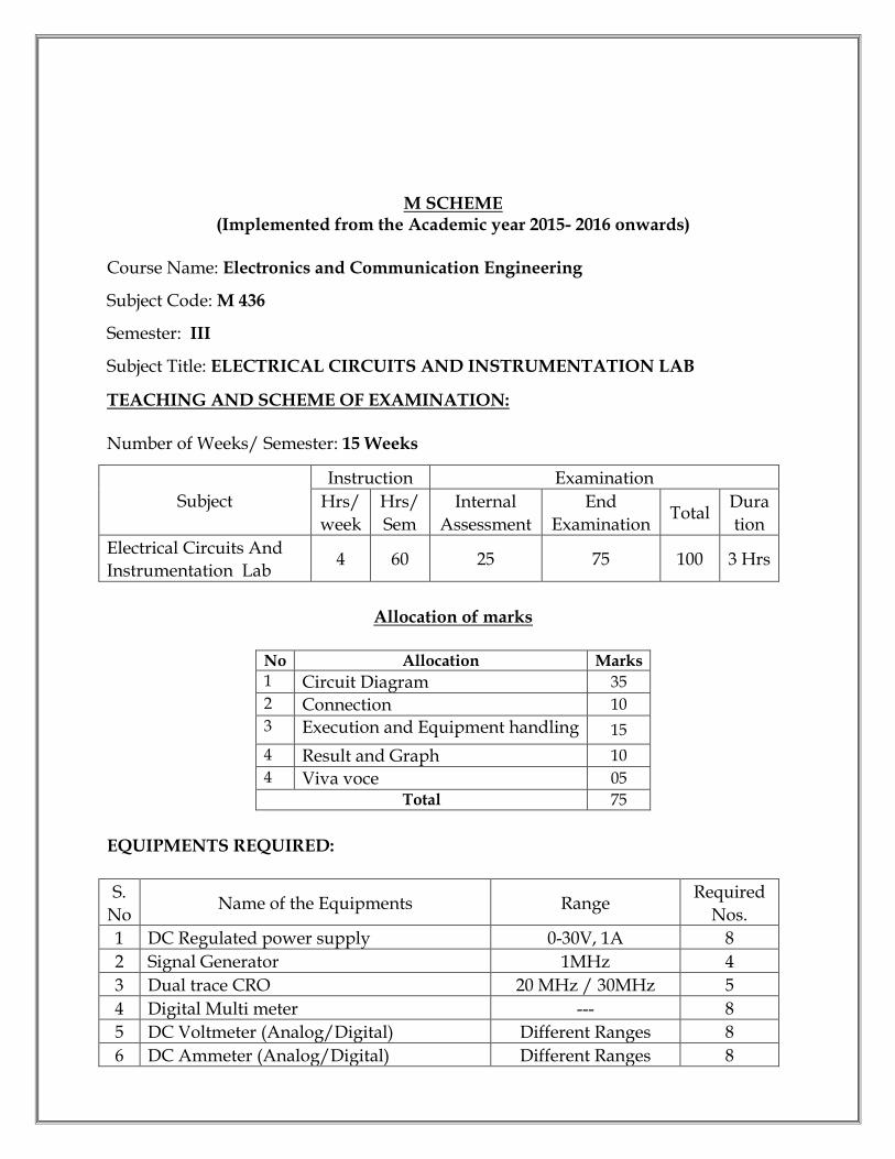
Course Name: Electronics and Communication Engineering
Subject Code: M 436
Semester: III
Subject Title: ELECTRICAL CIRCUITS AND INSTRUMENTATION LAB
TEACHING AND SCHEME OF EXAMINATION: Number of Weeks/ Semester: 15 Weeks
Subject
Instruction Examination
Hrs/
week
Hrs/
Sem
Internal
Assessment
End
Examination Total
Dura
tion
Electrical Circuits And
Instrumentation Lab 4 60 25 75 100 3 Hrs
Allocation of marks
No Allocation Marks
1 Circuit Diagram 35
2 Connection 10
3 Execution and Equipment handling 15
4 Result and Graph 10
4 Viva voce 05
Total 75
EQUIPMENTS REQUIRED:
S.
No Name of the Equipments Range
Required
Nos.
1 DC Regulated power supply 0-30V, 1A 8
2 Signal Generator 1MHz 4
3 Dual trace CRO 20 MHz / 30MHz 5
4 Digital Multi meter --- 8
5 DC Voltmeter (Analog/Digital) Different Ranges 8
6 DC Ammeter (Analog/Digital) Different Ranges 8
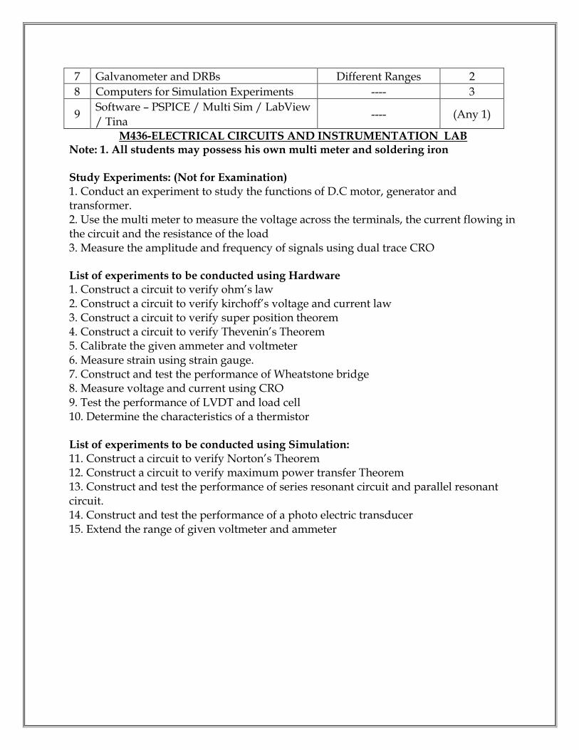
7 Galvanometer and DRBs Different Ranges 2
8 Computers for Simulation Experiments ---- 3
9 Software – PSPICE / Multi Sim / LabView
/ Tina ---- (Any 1)
M436-ELECTRICAL CIRCUITS AND INSTRUMENTATION LAB Note: 1. All students may possess his own multi meter and soldering iron Study Experiments: (Not for Examination) 1. Conduct an experiment to study the functions of D.C motor, generator and transformer. 2. Use the multi meter to measure the voltage across the terminals, the current flowing in the circuit and the resistance of the load 3. Measure the amplitude and frequency of signals using dual trace CRO List of experiments to be conducted using Hardware 1. Construct a circuit to verify ohm’s law 2. Construct a circuit to verify kirchoff’s voltage and current law 3. Construct a circuit to verify super position theorem 4. Construct a circuit to verify Thevenin’s Theorem 5. Calibrate the given ammeter and voltmeter 6. Measure strain using strain gauge. 7. Construct and test the performance of Wheatstone bridge 8. Measure voltage and current using CRO 9. Test the performance of LVDT and load cell 10. Determine the characteristics of a thermistor List of experiments to be conducted using Simulation: 11. Construct a circuit to verify Norton’s Theorem 12. Construct a circuit to verify maximum power transfer Theorem 13. Construct and test the performance of series resonant circuit and parallel resonant circuit. 14. Construct and test the performance of a photo electric transducer 15. Extend the range of given voltmeter and ammeter

M SCHEME (Implemented from the Academic year 2015- 2016 onwards)
Course Name: Electronics and Communication Engineering
Subject Code: M 437
Semester: III
Subject Title: COMPUTER APPLICATIONS LAB
TEACHING AND SCHEME OF EXAMINATION: Number of Weeks/ Semester: 15 Weeks
Subject
Instruction Examination
Hrs/
week
Hrs/
Sem
Internal
Assessment
End
Examination Total
Dura
tion
Computer Applications
Lab 4 60 25 75 100 3 Hrs
Allocation of marks
No Allocation Section I Section II
1 Procedure 10 10
2 Execution 20 20
3 Result 10
4 Viva voce 05 Total 75
EQUIPMENTS REQUIRED:
S.No Name of the Equipments Required Nos.
1 Desktops and Laptops 6
2 Laser Printer 1
3 OS Windows XP / Windows 7 / Windows 8 / Linux
4 Software Microsoft Office 2007/2010 /2013 (or) Open Office
M437 -COMPUTER APPLICATIONS LAB List of experiments to be conducted 1. WINDOWS

Introduction- History of Windows- screen saver and monitor resolution – Wallpaper setting-Folder manipulation – properties of a folder – Recycle bin – Short cuts – Sorting Folder –Switching between Application – Copying in CD/DVD settings – Recording Audio files. Exercises 1) a. Installing screen saver and change the monitor resolution by 1280X960
b. Setting wall papers c. Creating, moving, deleting and renaming a folder d. Copy, paste and cut a folder/file e. Displaying the properties for a file or folder
2) a. Restoring files and folders from Recycle bin b. Creating short cuts for folder/file c. Finding a file or folder by name d. Selecting and moving two or more files/folders using mouse e. Sorting folders/files.
3) a. Copying files into CD/DVD b. Switching between applications c. Making the taskbar wider and hiding the taskbar d. Recording and saving an audio file e. Set/Change the date and time.
2. WORD PROCESSING Introduction to Word Processing – Examples- Creation of new documents, opening document, insert a document into another document. Page setup, margins, gutters, font properties, Alignment, page breaks, header footer deleting, moving, replace, editing text in document. Saving a document, spell checker. Printing a document. Creating a table, entering and editing, Text in tables. Changing format of table, height width of row or column. Editing, deleting Rows, columns in table. Borders, shading, Templates, wizards, drawing objects, mail merge. Exercises 4) Creating a time table and perform the following operations on the table created
a)Different alignments b)Applying borders and colors c) Changing the width of row and column d) merge and split different cells in the table e) Insert and delete rows and columns at various positions
5) Create a standard covering letter and use mail merge to generate the customized
letters for applying to a job in various organizations. 6) Create a news letter with following and perform the following tasks:

a) multiple columns text b) differentformatting like font type, font size and font style etc. c) applyingwatermark d) header, footer and page number e) applyingbullets and numbers. f) inserting a clip art
3. SPREADSHEET Introduction – Menus – Tool bar – Create – Edit – Save – Formatting cells – Chart wizard – FillColors – Creating and using formulas – Sorting – Filtering. Exercises 7) Create a spread sheet and perform the following functions.
a) Auto sum b) functions such as greater than, less than and equal to etc. c) Filter option d) auto fill option
8) Create a spread sheet and perform the given functions below a) Format with two decimal places b) Format with text and apply conditional formatting c) Freeze column d) Sort
9) Create a spread sheet and prepare the following charts a) line chart b) barchart c) pie chart
4. PRESENTATION Introduction – Menus – Tool bar – Create – Edit – Save – Slide transition – Insert image – Hyperlink – Slide numbers – View slide show with sound – Photo album – Clip art. Exercises 10) Make a presentation to implement different animation effects on pictures and clip art. 11) Create a Presentation with different slide transitions and sound effect. 12) Create a photo album in PowerPoint. 5. INTERNET PRACTICE 13. a) Search a given topic in web using different search engines (Google, Yahoo etc.) b) Create a presentation on Google docs. Study about the review, comment and discussion options 14. Create a mail account using Gmail Service and study the following options a) Compose, Draft, Inbox, Sent Items, Attach. b)Make own signature and add it in mail c) CC and BCC options

15.a) Study of Google Map and make a report on the places like Hotels, Hospitals and petrol bunks etc. b) Create a blog in web
M SCHEME (Implemented from the Academic year 2015- 2016 onwards)
Course Name: Electronics and Communication Engineering
Subject Code: M 441
Semester: IV
Subject Title: COMMUNICATION ENGINEERING
TEACHING AND SCHEME OF EXAMINATION: Number of Weeks/ Semester: 15 Weeks
Subject
Instruction Examination
Hrs/
week
Hrs/
Sem
Internal
Assessment
End
Examination Total
Dura
tion
CommunicationEngineering
6 90 25 75 100 3 Hrs
Topics and allocation of hours
Unit Topic Time (Hrs)
I Networks, Antenna and Propagation 14
II Amplitude Modulation 16
III Angle and Pulse Modulation 15
IV Audio systems 15
V Video Systems 15
Revision and Test 15
Total 90
RATIONALE:
Today communication engineering has developed to a great extent that there is always the need for study of various communication concepts. This subject fulfills the need for students to have a thorough knowledge of various types of networks, modulation, audio systems and video systems. OBJECTIVES: On completion of the following units of syllabus contents, the students must be able to:
On completion of the following units of the syllabus contents, the students
must be able to

Understand the principles of working of antennas
Understand the theory of Propagation
Understand the concept of modulation
Study Amplitude Modulation Process
Learn about different types of AM Transmitter & receiver
Study the Frequency Modulation Process
Learn about different types of FM Transmitters & Receivers
Understand the concept Phase Modulation
Understand the concept Pulse Modulation
Learn Different types of Microphones
Learn Different types of Loudspeakers
Understand the different methods of Audio Recording & Reproduction
Understand the principles of Monochrome &colour TV Related Topics
M 441 - COMMUNICATION ENGINEERING Unit I: Networks, Antenna and Propagation Networks (qualitative treatment only):Symmetrical and asymmetrical networks - characteristic impedance and propagation constant. Equaliser: Types, constant resistance equalizer and applications of equalizers. Attenuator: Types - symmetrical T and Pi attenuators – applications and simple problems Filters:Types and definitions – circuit elements and cut off frequencies of LPF, HPF and BPF. Antennas: Basic antenna principle - polarization, directive gain, directivity, radiation pattern - folded dipole - parasitic array - broad-side and end-fire array- Yagi antenna and parabolic antenna Propagation: (short theory only) Ground wave propagation, sky wave, space wave propagation, ionospheric layers Unit II: Amplitude Modulation Modulation: Frequency spectrum. Relationship between wavelength and frequency, Need for modulation, types of modulation. Amplitude modulation: Expression, AM spectrum and side bands, types of AM - balanced modulator - SSB generation – phase shift and filter methods, advantages and disadvantages of SSB. AM-VSB system - Diode detector. AM Transmitter: Types of transmitters - high level AM transmitter and low level AM transmitter - SSB transmitter. AM Receiver: TRF receiver, super heterodyne radio receiver- Selection of IF- Image frequency - AGC types - SSB receiver.

UNIT III: Angle and Pulse Modulation Frequency modulation: Expression waveforms - frequency spectrum, effects of noise in FM, comparison of AM and FM, varactor diode modulator - FM detectors – slope detector, phase discriminator, ratio detector (qualitative treatment only) FM Transmitters & Receiver: Direct and Indirect methods- stereophonic FM transmitter - FM receiver: Block diagram – AFC-stereophonic FM receiver. Phase modulation: Principles, phase modulator circuit, comparison between FM and PM Pulse modulation: Types, sampling theorem. Generation and detection of PAM, PWM, PPM, PCM, DPCM, Delta modulation– quantizing noise- companding. Unit IV: Audio systems Microphones: (Qualitative treatment only) Construction and performance of the following microphones: carbon, condenser, piezo-electric, moving coil and velocity ribbon. Loud speakers:Constructional details of dynamic cone type, Horn type and electro-static loud speakers, woofer, midrange and tweeter, cross-over network. Surround-sound systems Audio recording and reproduction: Compact disc system- MP3 system - DVD system - stereophonic system - Hi-Fi system principles- Dolby -DTS Unit V: Video Systems Monochrome Television: Scanning principles - synchronization - aspect ratio- composite video signal- TV broadcasting standards. TV transmitter- TV receiver. ColourTV :Principles of colour transmission and reception- color CCD camera. PAL colour TV receiver (IC details not required) - Video basics:Panel Displays – Principles of LED, LCD and TFT and Plasma Displays - resolution – interlacing - refresh rate – dot pitch – data projectors – touch screens - Principles of Handy cam, CCTV and cable TV. Reference books 1. Networks lines and fields – John D.Ryder, PHI 2. Electronic communication Systems – Kennedy – TMH 3. Fundamentals of Acoustics – Kingsler&frey – Wiley Eastern ltd. 4. TV and Video engineering – ArvindM.Dhake – TMH. 5.Audio and Video system – Principles, maintenance and Troubleshooting by R.GuptaSecond Edition McGrawHill Education (P) Ltd.

M SCHEME (Implemented from the Academic year 2015- 2016 onwards)
Course Name: Electronics and Communication Engineering
Subject Code: M 442
Semester: IV
Subject Title: MICROPROCESSORS
TEACHING AND SCHEME OF EXAMINATION: Number of Weeks/ Semester: 15 Weeks
Subject
Instruction Examination
Hrs/
week
Hrs/
Sem
Internal
Assessment
End
Examination Total
Dura
tion
Microprocessors 6 90 25 75 100 3 Hrs
Topics and allocation of hours
Unit Topic Time (Hrs)
I Organization and Instruction set of 8085 Microprocessor 17
II Timing Diagrams and data transfer schemes 14
III Interrupts and memory interface 15
IV Peripheral interfacingand Applications of 8085 15
V Advanced Microprocessors and Bus standards 14
Revision and Test 15
Total 90
RATIONALE: This course introduces microprocessor architecture and discusses the design of systems based on micro processors. The purpose of this subject is to cover the underlying concepts and techniques used in Micro Processor and Interfacing. It also briefs the students about interfacing of memory and I/O devices like A to D converter, D to A converter LED, LCD etc The course will cover 8085 in detail with sufficient exposure to the industrial applications. OBJECTIVES: On completion of the following units of syllabus contents, the students must be able to:
To understand the history and need of Microprocessor.
To understand the internal architecture details of 8085 Microprocessor.

To know the instruction set of 8085
To learn different timing diagrams of 8085
To know different data transfer scheme of 8085 µP
To understand Interrupt Structure of 8085
To understand the interfacing techniques of memory and 8085 processor
To study different peripherals such as 8255, 8257, 8259, 8251 and 8279 ICs and their functions
To know different applications of 8085 µP
To learn different type of advanced microprocessors
M442 - MICROPROCESSORS Unit - I Organization and Instruction set of 8085 Microprocessor Organization of microprocessor: Block diagram and operation of a general Microprocessor system –Evolution Of Microprocessors –Features of 8085 Microprocessor – Bus structure of 8085 - Architecture – Pin details – Flag register – clock and reset circuit - Control and Status signals - demultiplexing of address and data bus. Instruction set of 8085: Instruction format – Addressing modes – Classification of instructions - data transfer, arithmetic, logical, branching, machine control – Stack and Subroutine Unit - II Timing Diagrams and data transfer schemes Timing diagrams: Processor cycles – Definition of Processor cycles (T- State, Machine cycle, Execution cycle, Fetch cycle) – Timing Diagram for Opcode FETCH, Memory READ, memory WRITE, I/O READ, and I/O WRITE and INTA̅̅ ̅̅ ̅̅ ̅- Timing diagram for MOV instruction and LDA only – Ready and Wait state (principle only) Data transfer schemes in 8085: Synchronous data transfer – asynchronous data transfer – Interrupt driven data transfer – DMA data transfer – three modes (single, block and demand transfer mode) - 8257 DMA controller – Block diagram and working principle Unit III - Interrupts and memory interface Interrupts of 8085: Interrupt system of 8085 - Hardware and software interrupts in 8085 – Interrupt vector table of 8085 – Polling –hardware and Software polling –Programmable Interrupt controller IC 8259A – Block diagram – Signal diagram – Working principle. Interfacing of memory: Address space partitioning - Memory mapped I/O and I/O mapped I/O - Organization of RAM IC 6264 – Interfacing 8085 Microprocessor with IC 2764 and 6264 Unit IV- Peripheral interfacingand Applications of 8085(No programs needed) PPI interface:

Interfacing with Programmable Peripheral Interface IC 8255 – Block diagram – Signal diagram – Control word format (I/O and BSR mode) - Working principle – Different Mode of operation (Mode 0, Mode1 and Mode2 - Concept only) Other peripheral interfaces: Interfacing with USART IC 8251 – Block diagram – Signal diagram – Working principle - Interfacing with Keyboard and display controller IC 8279 – Block diagram – Working principle Applications of Microprocessors: [No programs needed]Seven segment display interface –Stepper motor controller – Traffic light controller– waveform generation (sine wave, square wave and triangular wave) Unit V - Advanced Microprocessors and Bus standards Coprocessors:Basic principles of coprocessors - CISC Processors: Introduction to x86 processor – Architecture – BIU-IU-cache - FPU-MMU - The register set – Data format – Segmentation and Paging Pentium Processor: Features - Block diagram – Pipeline structure –Features of dual core processors. Bus standards: Need and types of bus standards- RS 232 serial Interface–I2C- USB Bus standard Reference Books: 1.MicroprocessorArchitechture Programming and Applications – Ramesh. S. Goankar., Wiley Eastern Ltd. 2.Microprocessor and Applications – R. Thiyagarajan. 3.Microprocessors – Principles and Applications., Charles. M. Gilmore., TMH 4.Advanced Microprocessors - Daniel Tabak., McGrawhill
M SCHEME (Implemented from the Academic year 2015- 2016 onwards)
Course Name: Electronics and Communication Engineering
Subject Code: M 443
Semester: IV
Subject Title: LINEAR INTEGRATED CIRCUITS
TEACHING AND SCHEME OF EXAMINATION: Number of Weeks/ Semester: 15 Weeks
Subject
Instruction Examination
Hrs/
week
Hrs/
Sem
Internal
Assessment
End
Examination Total
Dura
tion
Linear Integrated
Circuits 6 90 25 75 100 3 Hrs
Topics and allocation of hours
Unit Topic Time (Hrs)
I Introduction To Operational Amplifiers 14
II Op-Amp Applications 17
III Voltage regulators and PLL 15
IV Waveform generators and Special Function ICs 15
V D/A and A/D Converters and their Applications 14
Revision and Test 15
Total 90
RATIONALE:
IC technology needs the fundamentals of Integrated Circuits for students regarding the application and special function ICs. The monolithic operational amplifier has become an important building block of linear integrated circuits and applications .This subject will impart in depth knowledge of operational amplifiers, their applications and also about various special function ICs like timer IC and regulator IC. OBJECTIVES: On completion of the following units of syllabus contents, the students must be able to:
To study basic Op-Amp and its characteristics

To study the op-amp applications To know about PLL & its applications
To learn about DAC and its types
To understand the ADC concepts and its types
To introduce special function IC – 555 timer
To study about applications of IC 555
To learn about fixed IC voltage regulators
To discuss about general purpose regulator using IC
To understand PLL & waveform generators.
M 443- LINEAR INTEGRATED CIRCUITS Unit – I Introduction To Operational Amplifiers IC fabrication: Classification of ICs – Advantages – fabrication process of Monolithic ICs – IC packages Operational amplifier: Basic differential amplifier – working principle - Definition and symbol of Op- Amp – Block diagram of Op - Amp - Characteristics of an Ideal Op-Amp – Op - Amp parameters (CMRR and Slew rate) - IC 741 Pin details and specifications - virtual ground Basic linear circuits: Inverting Amplifier, Non Inverting amplifier – sign changer – scale changer and Voltage follower Unit – II Op-Amp Applications Linear Applications of OP-AMP: Summing amplifier - Subracting Amplifier –Multiplier and divider - Comparator – Zero crossing detector - Integrator – Differentiator – Voltage to current converter – Current to voltage converter - V to F and F to V converters - Instrumentation Amplifier – pin detail and features of IC AD620 - Bar graph display - Pin detail and features of IC LM 3914 Non - Linear Applications of OP-AMP: Precision rectifier – Clipper – Clamper - LM 380 OP-Amp power amplifier - pin detail and features
Unit – III Voltage regulators and PLL (Qualitative treatment only) IC voltage regulators: Linear fixed voltage regulator - Positive voltage regulator using IC 78xx, negative voltage regulator using IC 79xx –Variable voltage regulator using 317 and 337– General purpose regulator using LM 723- Low and High voltage regulator using LM 723 PLL: Basic principles of PLL – Block diagram and Working Principle – Lock range – capture range - Applications of PLL – frequency translation – frequency multiplication Monolithic PLLs: IC 565 PLL - Pin diagram – Block diagram and working principle - IC 567 Tone decoder - DTMF generator IC 91215B and DTMF decoder ICMT 8870 - Pin diagram – Block diagram and working principle Unit – IV Waveform generators and Special Function ICs: (qualitative treatment only)

Active Filters (First order only): Low pass – High pass – Band pass – Band stop – Circuit and Principle (qualitative treatment only). Waveform generators: Square wave, triangular wave, sine wave, saw tooth - Function generator IC 8038 - block diagram and principle IC 555 Timer: Pin diagram of IC 555 – Functional Block diagram of IC555 – Applications – Astablemultivibrator – monostablemultivibrator – Schmitt trigger Unit – V D/A and A/D Converters and their Applications DAC: Weighted resistor and – 2R ladder DAC ADC: Dual slopeADCand Successive Approximation ADC - block diagram and working principle. Monolithic ADC and DAC: ADC 0804 – DAC 1408 – Block diagram and working principle - Specifications of ADC / DAC (Accuracy, Resolution, Monotonocity, Settling time) Sample and hold: Principle - circuit using LF 398A – Acquisition time – Aperture time. Applications of ADC and DAC: DVM –Listing the types of DVM - Block diagram of DVM (Successive approximation type only) – Digital Frequency counter - Block diagram and principle of a PC Based data acquisition system REFERENCE BOOKS:
1. Linear Integrated circuits – D.Roychoudhury&Shail .B. Jain – New age International Publishers – II Edition – 2004.
2. Operational Amplifiers and Linear Integrated circuits - Ramakant .A Gayakwad – Prentice Hall – 2000.
3. Linear Integrated Circuits by Salivahanan&V.S.Kanchana Baskaran-TMH-2008 4. Introduction to system design using IC -B.S. Sonde – Wiley Eastern Limited – II
Edition – 1992

M SCHEME (Implemented from the Academic year 2015- 2016 onwards)
Course Name: Electronics and Communication Engineering
Subject Code: M 444
Semester: IV
Subject Title: PROGRAMMABLE LOGIC CONTROLLER
TEACHING AND SCHEME OF EXAMINATION:
Number of Weeks/ Semester: 15 Weeks
Subject
Instruction Examination
Hrs/
week
Hrs/
Sem
Internal
Assessment
End
Examination Total
Dura
tion
Programmable Logic
Controller 6 90 25 75 100 3 Hrs
Topics and allocation of hours
Unit Topic Time (Hrs)
I Fundamentals of programmable Logic Controller 17
II Basic fundamentals of PLC Programming 15
III PLC wiring and ladder diagrams for field devices 14
IV PLC Timer and counter programming 15
V Process control and data acquisition system 14
Revision and Test 15
Total 90
RATIONALE:
Programmable Logic Controller is the mandatory for the control Engineers in any Process Industry. As it is the default controller being used in the industries in automation of process such as packing, discrete control etc., It is obvious for the instrumentation and control Engineer to understand Hardware and programming the PLC. OBJECTIVES:
On completion of the following units of syllabus contents, the students must be able to:
To understand the detailed Hardware of PLC and its parts
To understand the working of PLC and scan cycle
T o understand the program and data memory organization
To know the Different timers of PLC and programming them
To know the different counters of PLC and its parameters
To understand the Ladder logic programming of PLC
To develop simple ladder programs
To study the Advanced instructions of PLC
To understand different process control systems of PLC
To learn about the basic concepts of SCADA and CIM
M 444 PROGRAMMABLE LOGIC CONTROLLER Unit - I Fundamentals of programmable Logic Controller: Definition - Advantages - Parts of PLC - Principle of operation - comparison between PLC and computer - classification of PLC - memory size - applications. I/O section - Discrete I/O modules - analog I/O modules - Special I/O modules - I/O specification - The CPU - programming devices - PLC work stations (Concept only) Unit - II Basic fundamentals of PLC Programming Logic fundamentals: AND, OR and NOT functions using switches - Boolean instructions and graphic symbols for various functions - Comparison of hardwired and programming logic Definition of relay ladder logic and ladder logic diagram - relay schematic and ladder logic diagram for the following logic gates AND, OR, NOT, NAND, NOR, EX-OR and EX-NOR. - relay schematic and ladder logic diagram for simple boolean equations (only two variables) - Programmable word level logic equations for AND, OR, NOT and EX-OR processor memory map –address format - program scan - PLC-User communication - relay type instructions (EXAMINE IF OPEN, EXAMINE IF CLOSED, and OUTPUT ENERGIZE) - instruction addressing - branch instruction (input, output and nested) Unit – III PLC wiring and ladder diagrams for field devices (Basic concepts only) Electromagnetic relay control - contactors - motor starters – manually operated switches(Push button, selector and DIP switches) - mechanically operated switches –(Level and Pressure switches) Sensors – Proximity sensor, light sensor, ultrasonic sensor – Bar code sensor - Magnetic reed switch - output control devices (Solenoid and stepper motor)- latching relays (basic principle only)– converting relay schematic into PLC ladder programs (basic concept only) - example conveyor belt Unit – IV PLC Timer and counter programming programming timers - timer instructions – quantities associated with timer - coil formatted and block formatted timer instructions –on delay timer - off delay timer -
retentive timer - ladder logic and principle of operation - cascading timers (basic concepts only) programming counters - counter instructions - up counter - down counter - cascading counter (basic concepts only) - combining counter and timer functions Unit –V Process control and data acquisition system Types of processes: continuous process, batch process - centralized and distributed control system (concept only) Structure of control system: components of a process control system Controllers: types of controller – Basic concepts of on-off, proportional, PID controllers Supervisory Control and Data Acquisition (SCADA):Block diagram and operation. Computer integrated manufacturing (CIM) - block diagram of different levels of CIM - Data communication - Network topology - master slave and peer to peer networks - I/O bus (device and process bus). Reference Books: 1. Programmable Logic Controller - Frank D. Petruzella - TMH - third Edition 2. Introduction to Programmable Logic Controller -Gary Dunning - Thomson Delmar 3. Programmable Logic Controllers; Principles and applications - Jhon W Webb Ronald A Rels - PHI 4. Exploring Programmable Logic Controllers with applications - Srivastava - BPB
M SCHEME
(Implemented from the Academic year 2015- 2016 onwards) Course Name: Electronics and Communication Engineering
Subject Code: M 445
Semester: IV
Subject Title: MICROPROCESSORS LAB
TEACHING AND SCHEME OF EXAMINATION: Number of Weeks/ Semester: 15 Weeks
Subject
Instruction Examination
Hrs/
week
Hrs/
Sem
Internal
Assessment
End
Examination Total
Dura
tion
Microprocessors Lab 4 60 25 75 100 3 Hrs
Allocation of marks
No Allocation Marks
1 Program 35
2 Algorithm / Flowchart 10
3 Execution and Result 25
4 Viva voce 05
Total 75
EQUIPMENTS REQUIRED:
S.
No Name of the Equipments Range
Required
Nos.
1 Microprocessor Trainer Kits 8085 P 8
2 Add on Boards for interfacing experiments --- Each 1
3 Software – Sim 8085 / GNU 8085 / Proteus ---- (Any 1)
M445 – MICROPROCESSORS LAB Study Experiments: (Not for Examination) 1.Study the microprocessor 8085 kit and identify the various functions of each key.

List of experiments to be conducted using Microprocessor Kit (Hardware) 1. 8 bit addition using different addressing modes (direct, register, register indirect and immediate) 2. Multi-byte addition 3. 8 bit subtraction, multiplication and division 4. Finding the smallest and largest value in an array 5. Arranging the given data in ascending order and descending order. 6Code conversions: a) BCD to Hexa conversion and vice versa b) Binary to Grey and vice versa 7. To fill a given data in 50 Locations in memory. 8. Program to convert Hexa to ASCII conversion and vice versa using look up table 9. Odd and even parity generators Interfacing experiments: 10. I/O operations using switches and LEDswith 8085 through 8255 11. Interfacing of seven segment display 12. Generating waveforms (square, sine and triangular) 13. Stepper motor control 14. Traffic light controller List of experiments to be conducted using Simulator (Software): 15. Sum of datain a given array 16. BCD addition and subtraction. 17. Generate the fibonacci series 18. Block transfer of data with and without overlapping

M SCHEME (Implemented from the Academic year 2015- 2016 onwards)
Course Name: Electronics and Communication Engineering
Subject Code: M 446
Semester: IV
Subject Title: LINEAR INTEGRATED CIRCUITS LAB
TEACHING AND SCHEME OF EXAMINATION:
Number of Weeks/ Semester: 15 Weeks
Subject
Instruction Examination
Hrs/
week
Hrs/
Sem
Internal
Assessment
End
Examination Total
Dura
tion
Linear Integrated
Circuits Lab 4 60 25 75 100 3 Hrs
Allocation of marks
No Allocation Marks
1 Circuit Diagram 35
2 Connection & Execution 25
3 Result and Graph 10
4 Viva voce 05 Total 75
EQUIPMENTS REQUIRED:
S.
No Name of the Equipments Range
Required
Nos.
1 Software – LT Spice / Multi Sim /Tina /
ORCAD ---- (Any 1)
M446 - LINEAR INTEGRATED CIRCUITS LAB
Note: 1. All students may possess his own multimeter and soldering iron
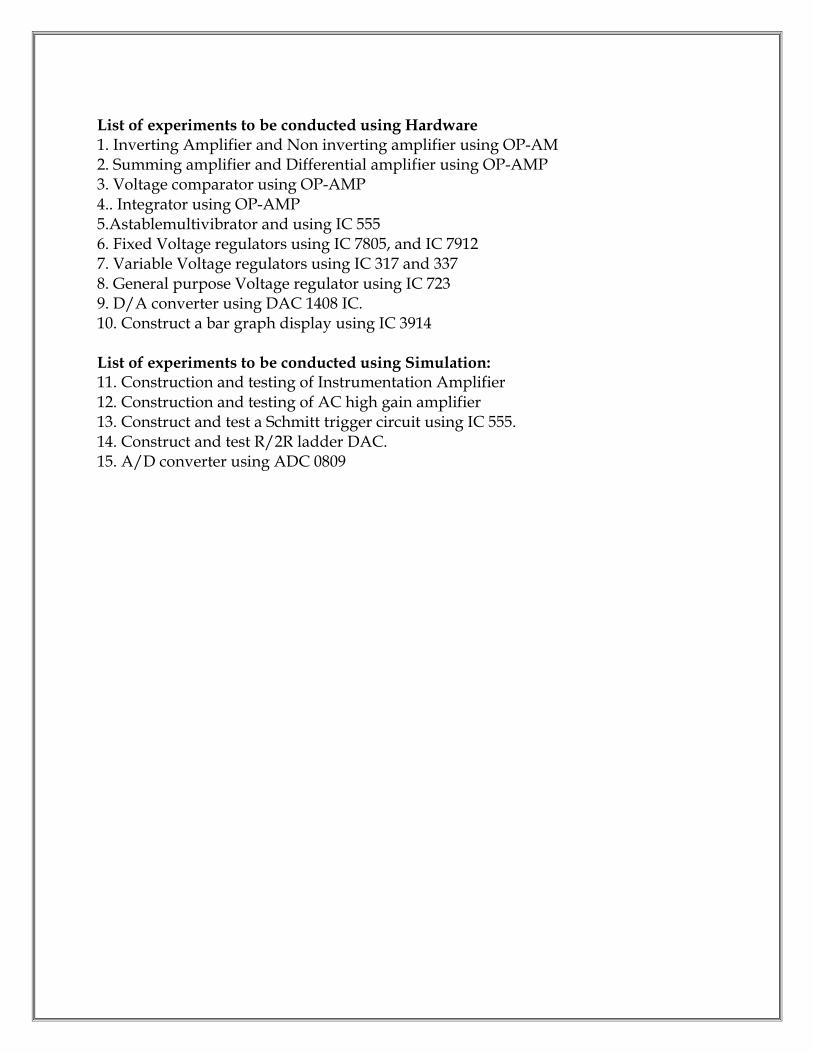
List of experiments to be conducted using Hardware 1. Inverting Amplifier and Non inverting amplifier using OP-AM 2. Summing amplifier and Differential amplifier using OP-AMP 3. Voltage comparator using OP-AMP 4.. Integrator using OP-AMP 5.Astablemultivibrator and using IC 555 6. Fixed Voltage regulators using IC 7805, and IC 7912 7. Variable Voltage regulators using IC 317 and 337 8. General purpose Voltage regulator using IC 723 9. D/A converter using DAC 1408 IC. 10. Construct a bar graph display using IC 3914 List of experiments to be conducted using Simulation: 11. Construction and testing of Instrumentation Amplifier 12. Construction and testing of AC high gain amplifier 13. Construct and test a Schmitt trigger circuit using IC 555. 14. Construct and test R/2R ladder DAC. 15. A/D converter using ADC 0809

M SCHEME (Implemented from the Academic year 2015- 2016 onwards)
Course Name: Electronics and Communication Engineering
Subject Code: M 447
Semester: IV
Subject Title: LIFE AND EMPLOYABILITY SKILLS LAB
TEACHING AND SCHEME OF EXAMINATION: Number of Weeks/ Semester: 15 Weeks
Subject
Instruction Examination
Hrs/
week
Hrs/
Sem
Internal
Assessment
End
Examination Total
Dura
tion
Life And Employability
Skills Lab 4 60 25 75 100 3 Hrs
Allocation of marks
Sl. No. Section No. of Hours
1
Part – A Communication
30
2
Part – B Entrepreneurship, Project Preparation
Productivity, Occupational Safety, Health, Hazard, Quality Tools & Labour Welfare
20
3
Part – C Environment, Global Warming, Pollution
10
TOTAL 60
RATIONALE: Against the backdrop of the needs of the Industries, as wells as based on fulfilling the expectations of the Industries, the Diploma Level students have to be trained directly and indirectly in toning up their competency levels. Proficiency in Communication only, equips them with confidence and capacity to cope with the employment. Hence, there is a necessity to focus on these in the curriculum. At the end of the Course, the student is better equipped to express himself in oral and written communication effectively.

SPECIFIC INSTRUCTIONAL OBJECTIVES
Emphasize and Enhance Speaking Skills
Increase Ability to Express Views & Opinions
Develop and Enhance Employability Skills
Induce Entrepreneurship and Plan for the Future
Expose & Induce Life Skills for Effective Managerial Ability
M447 - LIFE AND EMPLOYABILITY SKILLS LAB
Unit Topics Activities Hours
I Communication, Listening, Training, Facing Interviews, Behavioural Skills
-- instant sentence making -- say expressions/phrases -- self- introduction / another higher official in company
30
II
Entrepreneurship, Project Preparation, Marketing Analysis, Support & Procurement
-- prepare an outline of aproject to obtain loan frombank in becoming anentrepreneur -- prepare a resume
10
III
Productivity – comparison with developed countries, Quality Tools, Circles, Consciousness, Management, House Keeping
-- search in the website -- prepare a presentation -- discuss & interact
05
IV
Occupational Safety, Health Hazard, Accident & Safety, First- Aid, Labour Welfare Legislation, Welfare Acts
-- search in the website -- prepare a presentation -- discuss & interact
05
V
Environment, Global Warming, Pollution
-- taking down notes / hints -- answering questions -- fill in blanks the exactwords heard
10
LEARNING STRUCTURE 100 Marks
-- Focus more on Speaking & Listening Skills -- Attention less on Reading & Writing Skills -- Apply the skills in fulfilling the Objectives on Focused Topics --
a) Listening 25 Marks 1. Deductive Reasoning Skills (taking down notes/hints) 10 2. Cognitive Skills (answering questions) 10 3. Retention Skills (filling in blanks with exact words heard) 05 b) Speaking Extempore/ Prepared 30 Marks 1. Personality/Psychological Skills (instant sentence making) 05 2. Pleasing & Amiable Skills (say in phrases/expressions) 05

3. Assertive Skills (introducing oneself/others) 05 4. Expressive Skills (describe/explain things) 05 5. Fluency/Compatibility Skills (dialogue) 05 6. Leadership/Team Spirit Skills (group discussion) 05 c) Writing & Reading 20 Marks 1. Creative & Reasoning Skills (frame questions on patterns) 05 2. Creative & Composing Skills (make sentences on patterns) 05 3. Attitude & Aim Skills (prepare resume) 05 4. Entrepreneurship Skills (prepare outline of a project) 05 d) Continuous Assessment (Internal Marks) 25 Marks (search, read, write down, speak, listen, interact & discuss)
1. Cognitive Skills (Google search on focused topics) 2. Presentation Skills & Interactive Skills (after listening, discuss)
Note down and present in the Record Note on any 5 topics 10 Marks Other activities recorded in the Record note 10 Marks Attendance 05 Marks INTERNAL MARKS 25 Marks EXTERNAL MARKS AT END EXAMINATION 75 Marks
MODEL QUESTION Time: 3 Hours Max.Marks: 75 A. LISTENING 25Marks 1.Listen to the content and take down notes/hints 10 2.Listen to the content and answer the following questions. 10 3.Listen to the content and fill in the blanks the exact words heard. 05 B. SPEAKING 30 Marks 1.Say in a sentence instantly on hearing the word (5 words, one after another). 05 2. Say any five expressions commonly used in communication. 05 3. Imagine, a consultant has come to your department.Introduce him to your subordinates. 05 4.Explain/describe the product you are about to launch in the market. 05 5. Speak with your immediate boss about the progress you have made. 05 6.Discuss within the group on the topic of focus in the syllabus. 05 C. WRITING & READING 20 Marks 1. Frame new questions from the pattern given by changing sets of words with your own. 05
a. When Do you return?
b. How Is his performance?
c. Where Has the manager gone?

2. Make sentences from the pattern given by changing sets of words with your own.05
3. Prepare a resume for the post of Department Manager. 05 4. Prepare an outline of a project to obtain a loan. (Provide headings and subheadings) 05
-----
Guidelines for setting the question paper A. LISTENING: ONLY TOPICS related to POLLUTION /ENVIRONMENT /GLOBAL WARMING are to be taken.These topics are common for all the three types of evaluation. B. SPEAKING: WORDS of common usage Fragments – expression of politeness, courtesy, cordiality Introduce yourself as an engineer with designation or Introduce the official visiting your
company/department Describe/Explain the product/machine/department Dialogue must be with someone in the place of work. Group of six/eight Discuss the focused topic prescribed in syllabus
C. WRITING & READING:
Provide five different structures. Students are to substitute at least one with some otherword/words Provide five different structures. Students are to substitute at least one with some other word/words Provide some post related to industries. Outline of the project (skeleton/structure) Only the various headings and subheadings
Content is not needed
d. What Is the progress today?
e. Why Are the machines not functioning?
a. The workers are on strike
b. The labourers are paid well in this factory
c. There is a rest room for the workers
d. These are the new products launched by our company
e. Almost everyone come to the company on motorbikes

Guidelines for recording the material on the Focused Topics in the Record note. Write in the record note, on any five topics, from the list of topics given below. 10 Marks (5 topics x 10 marks = 50 marks. Thus, the Average of 5 topics is 10 Marks) 1. Productivity in Industries – Comparison with developed countries 2. Quality Tools, Quality Circles and Quality Consciousness 3. Effective Management 4. House Keeping in Industries 5. Occupational Safety and Hazard 6. Occupational Accident and First Aid 7. Labour Welfare Legislations 8. Labour Welfare Acts and Rights 9. Entrepreneurship 10. Marketing Analysis, Support and Procurement LABORATORY REQUIREMENT: 1. An echo-free room 2. Necessary furniture and comfortable chairs 3. A minimum of two Computers with internet access 4. A minimum of two different English dailies 5. A minimum of Three Mikes with and without cords 6. Colour Television (minimum size – 29”) 7. DVD/VCD Player with Home Theatre speakers 8. Smart board 9. Projector Suggested Reading: 1. Production and Operations Management by S.N. Chary, TMH 2. Essentials of Management by Koontz &Weihrich, TMH 3. Modern Production / Operations Management by E.S. Buffa and R.K. Sarin, John Wiley &
Sons 4. Production Systems: Planning, Analysis and Control by J.L.Riggs, 3rd ed., Wiley. 5. Productions and Operations Management by A.Muhlemann, J.Oakland and K.Lockyer,
Macmillan 6. Operations Research - An Introduction by H.A.Taha, Prentice Hall of India 7. Operations Research by J.K.Sharma, Macmillan 8. Business Correspondence & Report Writing by R.C. Sharma and K.Mohan, TMH 9. How to prepare for Group Discussion & Interview (With Audio Cassette) by Prasad, TMH 10. Spoken English – A self-learning guide to conversation practice (with Cassette) 11. Introduction to Environmental Engineering by Mackenzie, L. Davis and A. David, Cornwell,
McgrawHill, 3rd Ed. 12. Environmental Engineering by Peary, Rowe and Tchobanoglous, McgrawHill 13. Total Quality Management – An Introductory Text by Paul James, Prentice Hall 14. Quality Control and Applications by Housen&Ghose

15. Industrial Engineering Management by O.P. Khanna
M SCHEME (Implemented from the Academic year 2015- 2016 onwards)
Course Name: Electronics and Communication Engineering
Subject Code: M 451
Semester: V
Subject Title: ADVANCED COMMUNICATION SYSTEM
TEACHING AND SCHEME OF EXAMINATION:
Number of Weeks/ Semester: 15 Weeks
Subject
Instruction Examination
Hrs/
week
Hrs/
Sem
Internal
Assessment
End
Examination Total
Dura
tion
Advanced
Communication System 6 90 25 75 100 3 Hrs
Topics and allocation of hours
Unit Topic Time (Hrs)
I Telephone, FAX and Mobile Communication 15
II Radar And Navigational Aids 15
III Digital communication 15
IV Optical communication 15
V Satellite Communication 15
Revision and Test 15
Total 90
RATIONALE:
The introduction of this subject will enable the students to learn about the advancement in communication systems. It will give exposure to the various modes of communication viz Radar, Telephone, Fax, digital communication, digital codes, fiber optical communication, satellite communication, microwave communication, mobile communication and Satellite multiple access techniques.

OBJECTIVES: On completion of the following units of syllabus contents, the students must be able to:
To understand principles of Radar.
To understand principles of navigation aids
To study different microwave devices
To learn about the basic concepts of microwave communication system
To study electronics exchange and principles of facsimile communication.
To study basic digital communication system and digital codes.
To learn error detection and correction codes.
To learn various digital modulation techniques.
To understand optical communication system and discuss about fiber nodes, configurations and losses.
To learn optical sources, optical detectors.
To study satellite system, orbits, antennas
To understand fundamentals of microwave communication
To study fundamental cellular concepts such as frequency reuse, hand off
To learn multiple access techniques.
To learn digital cellular systems – GSM.
M451 ADVANCED COMMUNICATION SYSTEM Unit - I Telephone, FAX and Mobile Communication Telephony: Telephone system –Pulse and Tone dialling - Public switched Telephone network (PSTN) – Private Telephone Network - Electronic Switching System - Block diagram - Video phone – Block diagram – ISDN – Architecture - Features. FAX: Facsimile sender- Cylindrical scanning– Facsimile receiver - synchronization – phasing - Index of cooperation (IOC) - Direct recording and photo graphic recording. Mobile communication (Qualitative Treatment only): Cellular telephone - fundamental concepts – Simplified Cellular telephone system - frequency reuse – Interference – Co – Channel Interference – Adjacent Channel Interference – Improving coverage and capacity in cellular systems - cell splitting – sectoring - Roaming and Handoff – Basics of blue tooth technology. Unit - II Radar And Navigational Aids RADAR: Basic Radar System– Applications – Radar range equation (qualitative treatment only) – factors influencing maximum range – Basic PulsedRadar System – Block Diagram – Display Methods A - Scope, PPI Display - Automatic target detection. Radio aids to navigation:
Direction finding – Radio compass - Instrument landing system – Ground controlled approach system.
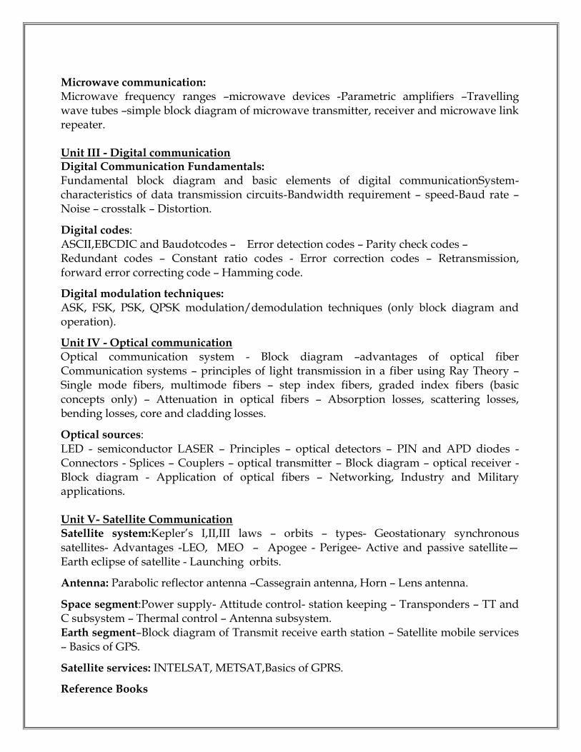
Microwave communication: Microwave frequency ranges –microwave devices -Parametric amplifiers –Travelling wave tubes –simple block diagram of microwave transmitter, receiver and microwave link repeater. Unit III - Digital communication Digital Communication Fundamentals: Fundamental block diagram and basic elements of digital communicationSystem-characteristics of data transmission circuits-Bandwidth requirement – speed-Baud rate – Noise – crosstalk – Distortion. Digital codes: ASCII,EBCDIC and Baudotcodes – Error detection codes – Parity check codes – Redundant codes – Constant ratio codes - Error correction codes – Retransmission, forward error correcting code – Hamming code. Digital modulation techniques: ASK, FSK, PSK, QPSK modulation/demodulation techniques (only block diagram and operation). Unit IV - Optical communication Optical communication system - Block diagram –advantages of optical fiber Communication systems – principles of light transmission in a fiber using Ray Theory – Single mode fibers, multimode fibers – step index fibers, graded index fibers (basic concepts only) – Attenuation in optical fibers – Absorption losses, scattering losses, bending losses, core and cladding losses. Optical sources: LED - semiconductor LASER – Principles – optical detectors – PIN and APD diodes - Connectors - Splices – Couplers – optical transmitter – Block diagram – optical receiver - Block diagram - Application of optical fibers – Networking, Industry and Military applications. Unit V- Satellite Communication Satellite system:Kepler’s I,II,III laws – orbits – types- Geostationary synchronous satellites- Advantages -LEO, MEO – Apogee - Perigee- Active and passive satellite—Earth eclipse of satellite - Launching orbits. Antenna: Parabolic reflector antenna –Cassegrain antenna, Horn – Lens antenna. Space segment:Power supply- Attitude control- station keeping – Transponders – TT and C subsystem – Thermal control – Antenna subsystem. Earth segment–Block diagram of Transmit receive earth station – Satellite mobile services – Basics of GPS. Satellite services: INTELSAT, METSAT,Basics of GPRS. Reference Books

1. Electronic communication systems - Kennedy - Davis - fourth Edition - Tata McGraw Hill - 1999. 2. Optical fiber communication - Gerd Keiser - Third Edition - McGraw Hill - 2000 3. Satellite communication - Dr. D.C. Agarwal - Third Edition - Khanna publishers - 1995 4. Electronic Communications systems - Fundamentals through Advanced - Wayne Tomasi - Fifth Edition - Pearson Education – 2005
M SCHEME
(Implemented from the Academic year 2015- 2016 onwards) Course Name: Electronics and Communication Engineering
Subject Code: M 452
Semester: V
Subject Title: MICROCONTROLLERS
TEACHING AND SCHEME OF EXAMINATION: Number of Weeks/ Semester: 15 Weeks
Subject
Instruction Examination
Hrs/
week
Hrs/
Sem
Internal
Assessment
End
Examination Total
Dura
tion
Microcontrollers 6 90 25 75 100 3 Hrs
Topics and allocation of hours
Unit Topic Time (Hrs)
I Organization of 8051 Microcontroller 15
II Instruction Set And Programming 17
III Timer, Interrupt and Serial Programming 17
IV 8051 advanced programming concepts: 12
V Interfacing of 8051 14
Revision and Test 15
Total 90
RATIONALE: Microcontroller is the sole of all embedded electronic equipments and is used in most of the areas of electronics. They include product ranges from tiny consumer electronic products to complex industrial process controllers. A diploma engineer needs to maintain such systems. Programming practices will further help the students to develop indigenous microcontroller based applications. OBJECTIVES: On completion of the following units of syllabus contents, the students must be able to:

Explain Architecture of 8051 Microcontroller.
Explain the functions of various registers.
Study the various instructions of 8051
Understand interrupt structure of 8051.
Understand serial data communication concepts.
Understand the programming techniques.
Explain various addressing modes.
Write programs for different types of timers and counters
Write Embedded C programs using 8051
Understand how to interface with RS232C.
Understand various application of 8051 Microcontroller
M452– Microcontrollers
Unit –I Organization of 8051 Microcontroller Architecture of 8051: Block diagram of a general microcontroller – Comparison with Microprocessor andMicrocontroller – Overview of 8051 family – Architecture of 8051 –ALU – Pin details of 8051 – Clock & Reset circuit–Program Counter – PSW register – register banks – Bank 1 and Stack conflict –I/O Ports– Bit addresses for I/O and RAM Memory structure of 8051: [7] Internal memory (ROM and RAM)– Special Function Registers –Memory Map of internal RAM (including registers and register banks) – Bit address for RAM - Code and data memory Unit II Instruction Set And Programming Assembling and running an 8051 program – Instruction set of 8051 –Addressing modes of 8051 – Data transfer instructions –Arithmetic Instructions – Logic and Compare instructions – Rotate and swap instructions– DA A–Bit manipulation instructions – Data serialization –Branching instructions: Loop and jump instructions –Call instructions – Time delay routines– 8051 I/O programming – I/O bit manipulation programming –Assembler directives Unit – III Timer, Interrupt and Serial Programming Timer registers (Timer 0 and timer 1) – Significance of TMOD and TCON registers – Different modes of Timer – Timer programming in Mode 1 and mode 2 –Counter programming in mode 1 and mode 2. 8051 Serial Port Programming Principles of asynchronous serial communication - Interfacing of RS 232 with 8051 – Importance of MAX 232 - Baud rate in 8051 - Significance of SCON and SBUF register - Programming the 8051 to transmit data serially - Programming the 8051 to receive data serially - Importance of PCON register 8051 interrupt programming:

Interrupts and their vector table of 8051 – IP and IE registers – Programming Timer Interrupts –Programming external hardware interrupts – Programming the serial communication interrupt– Interrupt priorities of 8051
Unit IV 8051 advanced programming concepts: C data types for 8051 – I/O programming in 8051 C (Byte addressable I/O – Bit addressable I/O – SFR I/O) – logic operations in 8051 C – Data conversion programs in 8051 C (Packed BCD to ASCII conversion, ASCII to Packed BCD conversion and vice versa, Binary to decimal, simple time delay) – Data serialization in 8051 C Unit – V Interfacing of 8051 Interfacing of external ROM with 8051 chip – Interfacing the LCD– Interfacing hex–keyboard and 8051 –DAC and ADC interfacing – sensor interfacing and signal conditioning– DS 12887 RTC interfacing –DC motor interfacing. REFERENCE BOOKS: 1. 8051 Microcontroller and Embedded Systems using Assembly and C by Mazidi, Mazidi and D.MacKinlay, 2006 Pearson Education Low Price Edition. 2. Microcontrollers, Principles and Applications – Ajit pal – PHI Ltd., - 2011. 3. Microprocessor and Microcontroller by R.Theagarajan, Sci Tech Publication, Chennai 4. 8051 Microcontroller by Kenneth J.Ayala.
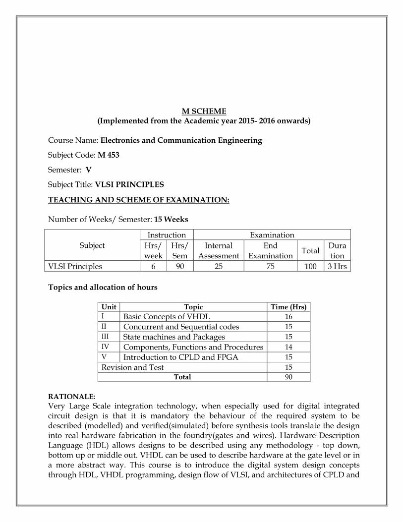
M SCHEME (Implemented from the Academic year 2015- 2016 onwards)
Course Name: Electronics and Communication Engineering
Subject Code: M 453
Semester: V
Subject Title: VLSI PRINCIPLES
TEACHING AND SCHEME OF EXAMINATION: Number of Weeks/ Semester: 15 Weeks
Subject
Instruction Examination
Hrs/
week
Hrs/
Sem
Internal
Assessment
End
Examination Total
Dura
tion
VLSI Principles 6 90 25 75 100 3 Hrs
Topics and allocation of hours
Unit Topic Time (Hrs)
I Basic Concepts of VHDL 16
II Concurrent and Sequential codes 15
III State machines and Packages 15
IV Components, Functions and Procedures 14
V Introduction to CPLD and FPGA 15
Revision and Test 15
Total 90
RATIONALE:
Very Large Scale integration technology, when especially used for digital integrated circuit design is that it is mandatory the behaviour of the required system to be described (modelled) and verified(simulated) before synthesis tools translate the design into real hardware fabrication in the foundry(gates and wires). Hardware Description Language (HDL) allows designs to be described using any methodology - top down, bottom up or middle out. VHDL can be used to describe hardware at the gate level or in a more abstract way. This course is to introduce the digital system design concepts through HDL, VHDL programming, design flow of VLSI, and architectures of CPLD and

FPGA. It is mainly aimed at design of combinational and sequential functions at gate / behavioral level and simulates and verifies their functionality using the VHDL. OBJECTIVES: On completion of the following units of syllabus contents, the students must be able to:
Understand device level implementation of digital gates.
Design a combinational circuit for any custom made application
Explain the building blocks for the combinational circuit
Develop a VHDL code for any combinational circuit
Answer the VHDL primitives and the importance of VHDL code in a digital circuit
Know the concurrent and sequential statements used for VHDL programming
Explain the style of Moore and Mealy type machines
Understand the basic concepts of packages, functions and procedures
Learn how to write the VHDL codes using component
Explain the importance of PROM, PLA, PAL and PLD
Differentiate between the PROM,PLA and PAL.
Understand the CPLD and FPGA hardware.
Describe ASICs
M - 453 VLSI PRINCIPLES Unit - I Basic Concepts of VHDL VHDL - Design flow - List of EDA tools available – Fundamentals VHDL units – List of VHDL libraries - Library declaration - Entity - Architecture Objects - Constants - Signals - Variables –Comparison of signal and variable - File - Data types - pre defined and user defined - sub types (enumerated) - arrays - records - Type conversion. Operators - Assignment, logical, relational, arithmetic, shift, concatenation - data and signal attributes - operator overloading - generic – Generic parity generator and parity detector Unit - II Concurrent and Sequential codes Concurrent code using operator - WHEN statement (WHEN ELSE - WITH SELECT) - 4 to 1 Multiplexor using the above statements GENERATE statement - BLOCK statement - Simple and gaurded block –Guarded block using D Latch PROCESS statement - IF statement - WAIT statement - WAIT UNTIL, WAIT ON, WAIT FOR - CASE statement - Comparison between WHEN and CASE – One digit decade counter using IF,WAIT and CASE.
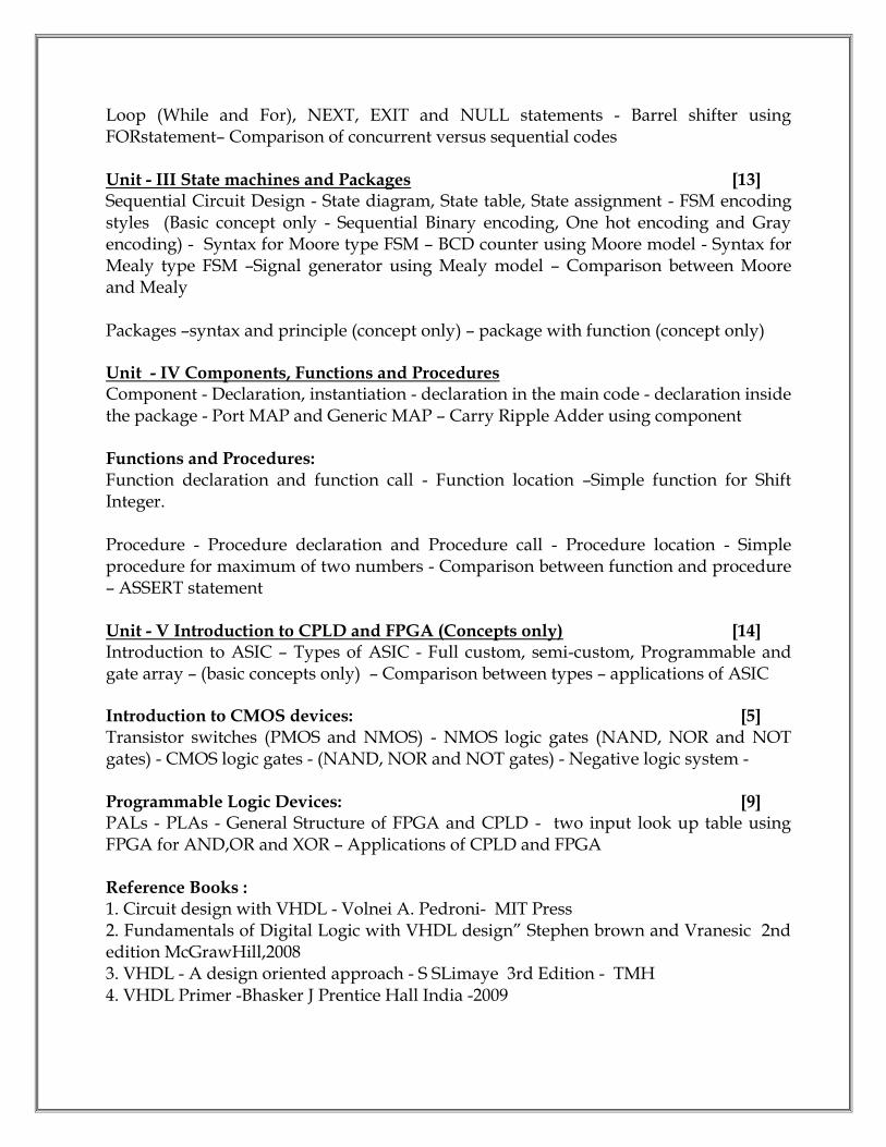
Loop (While and For), NEXT, EXIT and NULL statements - Barrel shifter using FORstatement– Comparison of concurrent versus sequential codes Unit - III State machines and Packages [13] Sequential Circuit Design - State diagram, State table, State assignment - FSM encoding styles (Basic concept only - Sequential Binary encoding, One hot encoding and Gray encoding) - Syntax for Moore type FSM – BCD counter using Moore model - Syntax for Mealy type FSM –Signal generator using Mealy model – Comparison between Moore and Mealy Packages –syntax and principle (concept only) – package with function (concept only) Unit - IV Components, Functions and Procedures Component - Declaration, instantiation - declaration in the main code - declaration inside the package - Port MAP and Generic MAP – Carry Ripple Adder using component Functions and Procedures: Function declaration and function call - Function location –Simple function for Shift Integer. Procedure - Procedure declaration and Procedure call - Procedure location - Simple procedure for maximum of two numbers - Comparison between function and procedure – ASSERT statement Unit - V Introduction to CPLD and FPGA (Concepts only) [14] Introduction to ASIC – Types of ASIC - Full custom, semi-custom, Programmable and gate array – (basic concepts only) – Comparison between types – applications of ASIC Introduction to CMOS devices: [5] Transistor switches (PMOS and NMOS) - NMOS logic gates (NAND, NOR and NOT gates) - CMOS logic gates - (NAND, NOR and NOT gates) - Negative logic system - Programmable Logic Devices: [9] PALs - PLAs - General Structure of FPGA and CPLD - two input look up table using FPGA for AND,OR and XOR – Applications of CPLD and FPGA Reference Books : 1. Circuit design with VHDL - Volnei A. Pedroni- MIT Press 2. Fundamentals of Digital Logic with VHDL design” Stephen brown and Vranesic 2nd edition McGrawHill,2008 3. VHDL - A design oriented approach - S SLimaye 3rd Edition - TMH 4. VHDL Primer -Bhasker J Prentice Hall India -2009

M SCHEME (Implemented from the Academic year 2015- 2016 onwards)
Course Name: Electronics and Communication Engineering
Subject Code: M 4541
Semester: V
Subject Title: BIO MEDICAL INSTRUMENTATION
TEACHING AND SCHEME OF EXAMINATION: Number of Weeks/ Semester: 15 Weeks
Subject
Instruction Examination
Hrs/
week
Hrs/
Sem
Internal
Assessment
End
Examination Total
Dura
tion
Bio Medical
Instrumentation 6 90 25 75 100 3 Hrs
Topics and allocation of hours
Unit Topic Time (Hrs)
I Bio Potential Electrodes And Recorders 15
II Therapeutic Instruments 15
III Clinical Instruments 15
IV Modern Imaging Techniques 15
V Telemedicine and Patient Safety 15
Revision and Test 15
Total 90
RATIONALE:
Bio medical engineering education is in the growing stage. But every year, there is a tremendous increase in the use of modern medical equipment in the hospital and health care industry therefore it is necessary for every student to understand the functioning of various medical equipments. This subject to enable the students to learn the basic principles of different biomedical instruments viz Clinical measurement, Bio - medical recorders, Therapeutic instruments, Biotelemetry and Modern imaging techniques instruments.

OBJECTIVES: On completion of the following units of syllabus contents, the students must be able to understand about:
The generation of Bio-potential and its measurement using various electrodes.
The measurement of blood pressure and lung volume.
The measurement of respiration rate.
The measurement of body temperature and skin temperature.
The principles of operations of ECG,EEG and EMG recorder.
The working principles of audio meter.
The principles of operations of pacemaker.
The basic principle of dialysis.
The basic principle of short wave diathermy.
The basic principle of ventilators.
The basic principle of telemetry and telemedicine.
The various methods of accident prevention and patient safety
The basic principle of various types of lasers.
M4541 - BIO MEDICAL INSTRUMENTATION Unit - I Bio Potential Electrodes And Recorders Bio Potentials: Resting and action potential – Bio Electric Potential –Components of Bio Medical Instrument System Electrodes: Electrode potential –Types of electrodes – Micro – Surface – Depth and Needle electrodes Bio Potential Recorders: Electrocardiograph (ECG) – ECG Lead configuration – ECG recording set up –Specifications of ECG recorder – clinical uses of ECG – Phonocardiography (principle and applications only) - Electroencephalography (EEG) – Origin of EEG – Brain waves – 10-20 lead system – recording Set up – Clinical uses of EEG Unit –II Therapeutic Instruments Cardiac pacemaker: Types - Comparison between External pace makers and implantablepacemaker – Operation of synchronous and asynchronous pacemakers Defibrillators: Types – AC – DC defibrillators Nerve and muscle stimulators: Definition of Electrotherapy – Waveforms used in stimulators – Working principle of Versatile Electro Diagnostic Stimulator Kidney machine: Dialysis – Hemo dialysis – Peritoneal dialysis - Comparison between hemo and peritoneal dialysis.
Unit – III Clinical Instruments Operation theatre measurements: Principle – working of Automatic Bekesy audiometer - Surgical Diathermy – Waveforms used in surgical diathermy – Block diagram – operation – Ventilator – block diagram and description Specialized medical instruments: Measurement of Blood pressure – Working principle and applications of Electromagnetic blood flow meter – blood pH – digital pH meter - Blood Cell counter – diagram and principle Electron microscope: Construction and working principle – Comparison between optical microscope and electron microscope. Unit - IV Modern Imaging Techniques X ray, CT scan and laser beam: X ray apparatus – block diagram – Working Principle – Comparison between Radiography and Fluoroscopy –Angiography(Concept only) - Clinical uses of X- Ray Examination - Computer Tomography - Block diagram and operation – Applications. LASER in medical electronics: LASER beam properties and principle of operation – Applications of LASER in medicine. Advance medical instruments: Concepts and applications of Endoscope - Magnetic Resonance Imaging - Ultra sonic imaging - Bio feedback instrumentation – Block diagram and principle. Unit – V Telemedicine and Patient Safety Introduction to telemetry: Elements of Bio Telemetry system –Radio Telemetry system – Block diagram and working principle – Limitations and Applications. Safety Instrumentation: Radiation safety instrumentation – effect of radiation exposure – Radiation monitoring instruments – Pocket dosimeters and film dosimeters –Physiological effects due to 50Hz current passage Micro and macro shock – Electrical Accidents in hospitals – microshock and macro shock hazards – Devices to protect against electrical hazards - Ground fault circuit interrupter –Isolation transformer and line isolation monitor (concepts only) - Hospital Architecture Telemedicine: Introduction to Telemedicine:Telemedicine – Introduction – working – applications Reference Books: 1. Dr. M. Arumugam – Bio Medical Instrumentation ,Anuradha agencies, Publishers

2. Leslie Crom well – Fred.J. Weibell, Erich A.P Feither – Biomedica Instrumentation and measurement, II edition. 3. B.R. Klin – Introduction to Medical Electronics. 4. Kumara doss – Medical Electronics. 5. R. S. Khandpur – Handbook of Bio – Medical Instrumentation.
M SCHEME (Implemented from the Academic year 2015- 2016 onwards)
Course Name: Electronics and Communication Engineering
Subject Code: M 4542
Semester: V
Subject Title: ELECTRONIC SYSTEM DESIGN
TEACHING AND SCHEME OF EXAMINATION: Number of Weeks/ Semester: 15 Weeks
Subject
Instruction Examination
Hrs/
week
Hrs/
Sem
Internal
Assessment
End
Examination Total
Dura
tion
Electronic System
Design 6 90 25 75 100 3 Hrs
Topics and allocation of hours
Unit Topic Time (Hrs)
I Design of Power supply 15
II Design of small signal amplifiers 16
III Data acquisition system 14
IV Design of function generators 15
V High voltage/high current driver 15
Revision and Test 5
Total 90
RATIONALE:
The rationale behind introducing this subject is to make the students understand the structure, working and all other relevant aspects of electronic systems which has become an integral part of Electronic media which is growing at an exponentially high rate all around the world. OBJECTIVES: On completion of the following units of syllabus contents, the students must be able to:
To understand to design of DC regulated power supply of various voltages with different protection circuits.
To understand the design of different types of amplifiers for various application.
To understand the use of various transducers and make use them.
To design various systems using the analog data collected from transducers
To understand the use of microcontrollers for various application M – 4542ELECTRONIC SYSTEM DESIGN
UNIT I - Design of Power supply: DC power supply with filters, regulators & protection circuits, Multi output and variable power supply design. UNIT II - Design of small signal amplifiers: Emitter follower, Darlington pair amplifiers with and without Bootstrapping, Two stage direct coupled amplifiers. Design of audio power amplifier with drivers, Design of simple PA system Voltage to current converter, current to voltage converter. UNIT III - Data acquisition system: ADC, DAC, Design of Instrumentation amplifier with the bridge type transducer, Temperature measurement, Design of Electronic voltmeter and ammeter, Display system. UNIT IV - Design of function generators: Design of AM signal using multiplier IC, AM signal demodulation using envelope detector, Design of FM signal using VCO (using IC NE566). UNIT V - High voltage/high current driver: Circuit for Relay and motor control applications. Microcontroller based closed loop system, security systems, scrolling display; Microcontroller based stepper motor control system. REFERENCE BOOKS: 1. N.C.Goyel, R.K.Khetan, A Monograph on Electronic s Design Principles, Khanna Publishers 2. DC Power Supply Handbook, Agilent Technologies 3. The art of electronics by Paul Horowitz, Cambridge University Press
M SCHEME (Implemented from the Academic year 2015- 2016 onwards)
Course Name: Electronics and Communication Engineering
Subject Code: M 4543
Semester: V
Subject Title: ROBOTICS
TEACHING AND SCHEME OF EXAMINATION: Number of Weeks/ Semester: 15 Weeks
Subject
Instruction Examination
Hrs/
week
Hrs/
Sem
Internal
Assessment
End
Examination Total
Dura
tion
Robotics 6 90 25 75 100 3 Hrs
Topics and allocation of hours
Unit Topic Time (Hrs)
I Basic Concepts of Robotics 15
II Robot Hands 16
III Robot brain and muscles 14
IV Robot vision 15
V Applications of Robot 15
Revision and Test 5
Total 90
RATIONALE: Robotics is the science or study of the technology associated with the design, fabrication, theory, and application of robots. This course begins by introducing the subject of robotics, presents a brief history, types, classification and usage, and the science and technology of robots. Representation of joints, different kinds of actuators, sensors are presented in this subject. Robot grippers and manipulators are discussed in depth. Several applications in the field of Industrial and component handling, material handling, and manufacturing are discussed in details. OBJECTIVES:

On completion of the following units of syllabus contents, the students must be able to understand:
The basics of robot
Anatomy and working of Robot
End effectors and robot controls
Manipulators and grippers
Robot Transformations and Sensors
Robot drive mechanism
Safety consideration of Robot
Applications of Robot in various fields
Basic concept of SWARM Robot
M– 4543 Robotics
Unit - I Basic Concepts of Robotics Introduction to robots:Definition –Characteristics of a robot – Diffference between Human and the robot – Basic fundamentals of a robot (axis, Cartesian coordinates, rotate, translate, degree of freedom, home position, link and joints) – methods of positioning - Generations of robot – Benefits and shortcomings Anatomy of a robot – working principle of robot – Classification of robot - Motion control - Point to point and continuous path robot (principle only) – specifications for a robot- Components of a robot system Unit – II Robot Hands: End effectors: need for end effector – Types of end effector – Robot gripper – classification for grippers – criteria for selecting grippers –mechanical and magnetic grippers (basic principle only) - various gripping techniques Manipulator – Definition – function of a manipulator – requirements of interpolators – Hierarchical structure of a robot system –work place lay out of a robot Unit III – Robot brain and muscles: Robot controller – Definition - functions of a controller – structure of a robot controller - Control system - open loop and closed loop control system – feedback control system- applications of control system – Robot drive mechanisms: Linear, rotary and harmonic drive mechanisms Power systems for robot – Hydraulic, pneumatic, and electric power systems (DC motor, AC motor, servo motor and stepper motor) – diagram and working principle Unit IV: Robot vision List of sensors used in robot – Proximity and reed switches – Range and tactile sensors – Vision sensor – Light sensor – speed and sound sensors – displacement sensor – Heat sensors

Robot Safety consideration – Need for safety – Safety guidelines and checklists – Safety hazards Unit V: Applications of Robot Robot programming languages and operating systems (basic concepts only) Applications of Robots: List of applications for the following category: Industrial and Component handling Material handling applications (pick and place, palletizing and packaging – basic principle only) – Applications in the field of Manufacturing – Robots in the field of assembling and welding. Introduction to SWARM robots (principle only) –Perspectives of Future robots REFERENCE BOOKS
1. Robotics – Principels and practice – K.C. Jain, Dr. L.N.Agarwal – Khanna Publications
2. Robotics Technology and flexible automation – S.R.Deb, S.Deb – McGrawHill Publications
3. A text book on Industrial robotics - Ganesh. S. hegde - University science press

M SCHEME (Implemented from the Academic year 2015- 2016 onwards)
Course Name: Electronics and Communication Engineering
Subject Code: M 455
Semester: V
Subject Title: COMMUNICATION SYSTEM LAB
TEACHING AND SCHEME OF EXAMINATION: Number of Weeks/ Semester: 15 Weeks
Subject
Instruction Examination
Hrs/
week
Hrs/
Sem
Internal
Assessment
End
Examination Total
Dura
tion
Communication System
Lab 4 60 25 75 100 3 Hrs
Allocation of marks
No Allocation Marks
1 Circuit Diagram 35
2 Connection 10
3 Execution and Equipment handling 15
4 Result and Graph 10
4 Viva voce 05
Total 75
EQUIPMENTS REQUIRED:
S.No
Name of the Equipments Range Required
Nos.
1 DC Regulated power supply 0-30V, 1A 8
2 Signal Generator 1MHz 4
3 Dual trace CRO 20 MHz / 30MHz 4
4 Digital Multi meter --- 4

5 Fiber optic Kit --- 1
8 Computers for Simulation Experiments --- 3
9 Software – PSPICE / Multi Sim / ORCAD / Tina
--- (Any 1)
M455 - COMMUNICATION SYSTEM LAB List of experiments to be conducted using Hardware 1. Construct and test an AM modulator and detector circuit. 2. Determine the frequency response of the loudspeaker and microphone 3.Construct and test a three way crossover network. 4.Trace the input and output waveforms for ASK modulation and demodulation. 5. Set up and test the fibre optic analog and digital links. 6.Measure the bending loss and propagation loss in fiber optics. 7. Construct and test the performance of series and shunt equalizer 8. Construct and test symmetrical T and Pi attenuators. 9.Time Division Multiplexing of signals (Transmitter and Receiver) 10.Construct and test PCM transmitter and receiver circuits.
List of experiments to be conducted using Simulation 11. Trace the input and output waveforms for PSK modulation and demodulation. 12. Trace the input and output waveforms for FSK modulation and demodulation. 13. Construct and test an FM modulator circuit. 14.Construct and test PWM generation and detection circuits. 15.Construct and test PAM generation and detection circuits.

M SCHEME (Implemented from the Academic year 2015- 2016 onwards)
Course Name: Electronics and Communication Engineering
Subject Code: M 456
Semester: V
Subject Title: MICROCONTROLLER LAB
TEACHING AND SCHEME OF EXAMINATION: Number of Weeks/ Semester: 15 Weeks
Subject
Instruction Examination
Hrs/
week
Hrs/
Sem
Internal
Assessment
End
Examination Total
Dura
tion
Microcontroller Lab 4 60 25 75 100 3 Hrs
Allocation of marks
No Allocation Marks
1 Program 35
2 Algorithm / Flowchart 10
3 Execution and Result 25
4 Viva voce 05
Total 75
EQUIPMENTS REQUIRED: S.
No Name of the Equipments Range
Required
Nos.
1 Microcontroller Trainer Kits 8051 C 8
2 Add on Boards for interfacing experiments --- Each 1
3 Software – Proteus/ MCS 51 / KeilVision ---- (Any 1)
M 456 – MICROCONTROLLER LAB List of experiments to be conducted using hardware 1. Arithmetic operations (Addition, Subtraction, multiplication and division of 8 bits) 2. Programs to implement mathematical functions (8 bit operands only) a) square root b) GCD 3. Program for search a given character in a string. 4. Program to find the number of characters, words in sentence. 5. Check given string is palindrome or not (using index addressing mode) 6. Program using timer and counter (use timer 1 or timer 2) 7. Program using interrupt Interfacing with application boards 8. 4 bit binary counters (up, down, up down and ring) 9. 8 bit ADC interface 10. 8 bit DAC interface List of experiments to be conducted using simulation 11. Sending data through serial port between two micro controller kits 12. Read the temperature using LM 39 sensor. 13. LCD interface 14. DC Motor 15. Testing logic gates (Basic and Universal gates only)

M SCHEME (Implemented from the Academic year 2015- 2016 onwards)
Course Name: Electronics and Communication Engineering
Subject Code: M 457
Semester: V
Subject Title: VLSI LAB
TEACHING AND SCHEME OF EXAMINATION:
Number of Weeks/ Semester: 15 Weeks
Subject
Instruction Examination
Hrs/
week
Hrs/
Sem
Internal
Assessment
End
Examination Total
Dura
tion
VLSI Lab 4 60 25 75 100 3 Hrs
Allocation of marks
No Allocation Marks
1 Interfacing Circuit Diagram 10
2 Program 30
3 Execution and Result 20
4 Viva voce 05
Total 75
EQUIPMENTS REQUIRED:
S.
No Name of the Equipments Range
Required
Nos.
1 VLSI Trainer Kits SPARTRAN 3 / 3E
FPGA 8
2 Add on Boards for interfacing experiments --- Each 1
3 Software – Xilinx / Model Sim / Altera ---- (Any 1)
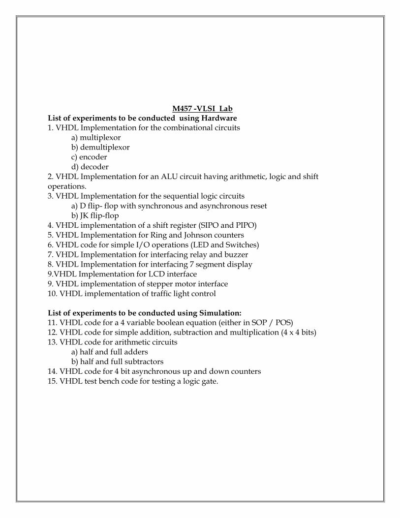
M457 -VLSI Lab List of experiments to be conducted using Hardware 1. VHDL Implementation for the combinational circuits a) multiplexor b) demultiplexor c) encoder d) decoder 2. VHDL Implementation for an ALU circuit having arithmetic, logic and shift operations. 3. VHDL Implementation for the sequential logic circuits a) D flip- flop with synchronous and asynchronous reset b) JK flip-flop 4. VHDL implementation of a shift register (SIPO and PIPO) 5. VHDL Implementation for Ring and Johnson counters 6. VHDL code for simple I/O operations (LED and Switches) 7. VHDL Implementation for interfacing relay and buzzer 8. VHDL Implementation for interfacing 7 segment display 9.VHDL Implementation for LCD interface 9. VHDL implementation of stepper motor interface 10. VHDL implementation of traffic light control List of experiments to be conducted using Simulation: 11. VHDL code for a 4 variable boolean equation (either in SOP / POS) 12. VHDL code for simple addition, subtraction and multiplication (4 x 4 bits) 13. VHDL code for arithmetic circuits a) half and full adders b) half and full subtractors 14. VHDL code for 4 bit asynchronous up and down counters 15. VHDL test bench code for testing a logic gate.

M SCHEME (Implemented from the Academic year 2015- 2016 onwards)
Course Name: Electronics and Communication Engineering
Subject Code: M 461
Semester: VI
Subject Title: INDUSTRIAL ELECTRONICS TEACHING AND SCHEME OF EXAMINATION:
Number of Weeks/ Semester: 15 Weeks
Subject
Instruction Examination
Hrs/
week
Hrs/
Sem
Internal
Assessment
End
Examination Total
Dura
tion
Industrial Electronics 6 90 25 75 100 3 Hrs
Topics and allocation of hours
Unit Topic Time (Hrs)
I Power Devices and Trigger Circuits 16
II Converters and Choppers 15
III Inverters & Applications 14
IV Power Electronic Control 15
V Numerical Control Systems 15
Revision and Test 15
Total 90
RATIONALE:
The rationale behind the modifying this subject is to give clear explanation of power devices and circuits that are widely used today in modern industry. It also gives exposure to PLCs & DCS which can perform various control functions in industrial environments. OBJECTIVES: On completion of the following units of syllabus contents, the students must be able to:
To Study working principle of MOSFET, IGBT
To Study the methods of triggering
To learn about converters and its types.
To understand commutation concepts in SCR
To learn about choppers.
To Study about inverters and types.

To understand the concept of HVDC.
To know about SMPS.
To understand about UPS and its types.
To understand the concepts of AC and DC drives
To study about the
M461 INDUSTRIAL ELECTRONICS Unit I - Power Devices and Trigger Circuits Thyristor family –Working principle, VI characteristics and applications of SCR – Definitions for holding current, latching current, dv/dt rating, di/dt rating. Insulated gate bipolar transistor(IGBT), MOSFET and GTO - Symbol, principle of working, VI characteristics and applications. Triggering of SCR - Gate triggering –Types –Concepts of DC triggering, AC triggering, Pulse gate triggering – Pulse transformer in trigger circuit – Electrical isolation by opto isolator -Resistance capacitor firing circuit and waveform, Synchronized UJT triggering (ramp triggering) - circuit and waveform. Unit II - Converters and Choppers (Qualitative Treatment Only) Converters – Definition – Single phase Half controlled bridge converter with R load and RL load - importance of flywheel diode –Single phase fully controlled bridge converter with resistive load – voltage and current waveforms – Single phase fully controlled bridge converter with RL load – voltage and current waveforms. Commutation- Natural commutation – Forced commutation – Types of forced commutation(mention the types only). Chopper – Definition –principle of DC chopper operation – Typical chopper circuit (Jones chopper) –Applications of DC chopper – Principle of working of single phase AC chopper -Chopper using MOSFET. Unit III - Inverters & Applications Inverter - Definition -Requirement of an inverter –Single phase inverter with resistive load –Single phase inverter with RL load –Methods to obtain sine wave output from an inverter-Output voltage control in inverters - McMurray inverter – advantages - Parallel inverter using IGBT. HVDC Transmission- principle – advantages – drawbacks, SMPS - Block diagram of SMPS – advantages and disadvantages. UPS-Type (ON Line, OFF Line), Comparison, Battery Banks. Unit IV-Power Electronic Control (Qualitativetreatmentonly-no derivations): Control of DC drives:
Introduction – Applications of DC drives – DC chopper for series motor drive, Fourquadrant DC – DC converter drive using MOSFET, Closed loop control of DC drives – Block description. Control of AC drives: Introduction – Applications of AC drives, Closed loop control of AC drives – Block description, Microcomputer based PWM control of induction motor drive-Block description. Cyclo Converter: Introduction, single phase to single phase cyclo converter with simple circuit. Power Electronic Applications: Simple battery charger circuit using SCR, Emergency lighting system – simple circuit, Simple Time-Delay Circuit using SCR and UJT. Unit V - Numerical Control Systems Basic concepts of numerical control - Block diagram of numerical control system– Advantages,disadvantages , applications of numerical control system –Programming systems (mention thenames only) – Data processing unit –Data reading – Part programming – steps - Post processor Introduction to CNC – Basic concepts of CNC – Comparison between NC & CNC – Typical CNC system – Block diagram, Advantages. REFERENCE BOOKS 1. Industrial & Power Electronics by Harish C.Rai, Umesh Publication, 5th Edition 1994 2. Power Electronics by Dr.P.S.Bimbhra, Khanna publishers -2nd Edition-1998 3. Power Electronics by M.H.Rashid-PHI Publication-3rd Edition-2005 4. Power Electronics by M.D.Singh&K.B.Khanchandani 2nd Edition-2011, TMH 5. Industrial Electronics and control by Biswanath Paul –PHI publications-2nd Ed. -2011 6. Numerical control of Machines – Yoram Korean & Joseph Ben
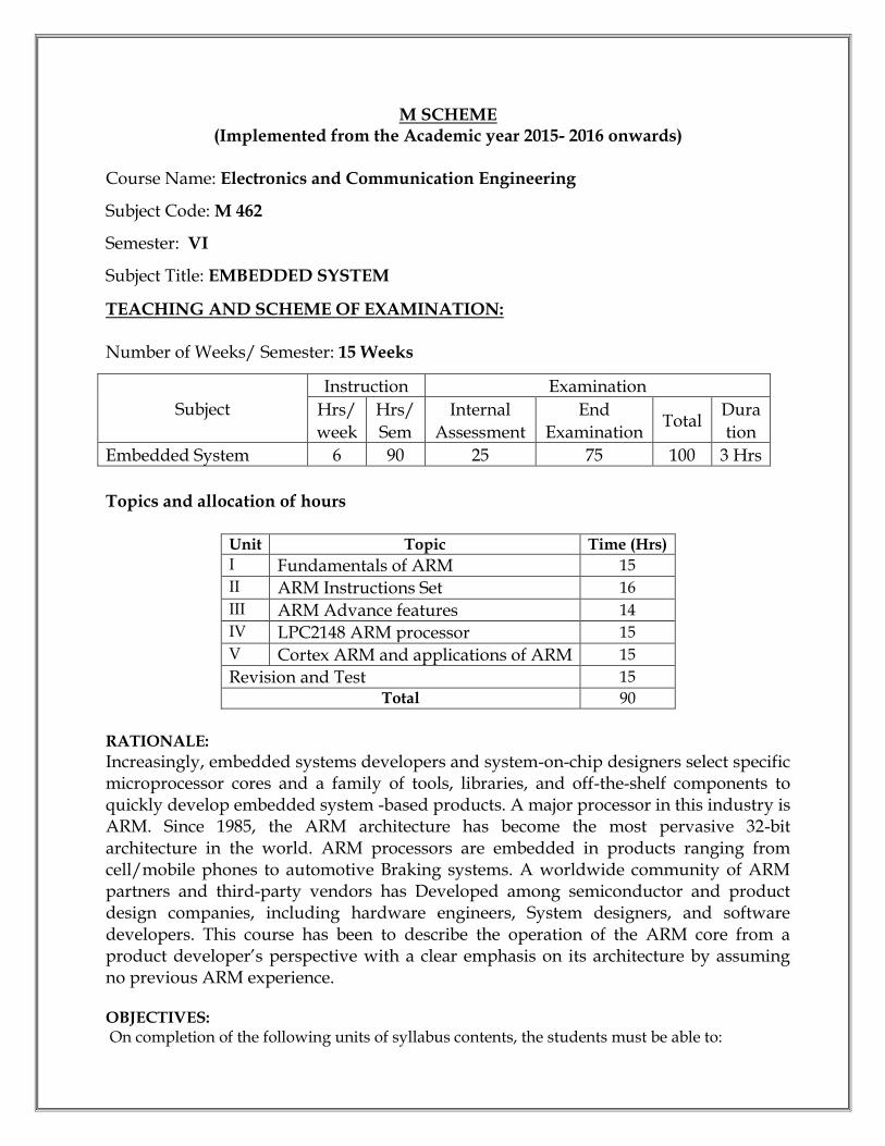
M SCHEME (Implemented from the Academic year 2015- 2016 onwards)
Course Name: Electronics and Communication Engineering
Subject Code: M 462
Semester: VI
Subject Title: EMBEDDED SYSTEM
TEACHING AND SCHEME OF EXAMINATION: Number of Weeks/ Semester: 15 Weeks
Subject
Instruction Examination
Hrs/
week
Hrs/
Sem
Internal
Assessment
End
Examination Total
Dura
tion
Embedded System 6 90 25 75 100 3 Hrs
Topics and allocation of hours
Unit Topic Time (Hrs)
I Fundamentals of ARM 15
II ARM Instructions Set 16
III ARM Advance features 14
IV LPC2148 ARM processor 15
V Cortex ARM and applications of ARM 15
Revision and Test 15
Total 90
RATIONALE:
Increasingly, embedded systems developers and system-on-chip designers select specific microprocessor cores and a family of tools, libraries, and off-the-shelf components to quickly develop embedded system -based products. A major processor in this industry is ARM. Since 1985, the ARM architecture has become the most pervasive 32-bit architecture in the world. ARM processors are embedded in products ranging from cell/mobile phones to automotive Braking systems. A worldwide community of ARM partners and third-party vendors has Developed among semiconductor and product design companies, including hardware engineers, System designers, and software developers. This course has been to describe the operation of the ARM core from a product developer’s perspective with a clear emphasis on its architecture by assuming no previous ARM experience. OBJECTIVES: On completion of the following units of syllabus contents, the students must be able to:

Distinguish between CISC and RISC architecture Understand the ARM design philosophy Explain the ARM architecture and the pipeline structure Describe the little and big endian methods of representation Explain the Instruction sets of ARM processor. Understand various operational modes in ARM processor List the various exceptions and handling methods Develop an assembly level code for basic arithmetic primitive operations Understand the cache mechanism and cache policies Explain the importance of memory protection Learn the architecture of LPC 2148 ARM processor Study the various peripherals related with LPC 2148 Know the basics of different Cortex family Learn different applications of ARM Relate and distinguish between OS and RTOS in their functionality.
M - 462 EMBEDDED SYSTEM
Unit - I Fundamentals of ARM RISC Processors: Introduction to RISC processors –Properties of RISC - CISC Versus RISC. Fundamentals of Embedded System: Definition of Embedded system – Requirements of embedded system - Features and Types of embedded system – Applications of Embedded system- Example using domestic refrigerator ARM processor fundamentals: Embedded System Hardware (ARM bus technology, AMBA bus protocol, memory and peripherals) - ARM coreData Flow model, Registers,Current Program Status Registerand banked registers,processor modes - states and instruction sets - Pipeline - Exceptions,Interrupts, and the Vector Table - ARMnomenclature and ARM families Unit - II ARM Instructions Set ARM Instruction Set - Data Processing Instructions- move, barrel shifter, arithmetic, logical, comparison and multiply- Branch Instructions, Load-Store Instructions- single and multiple register transfer, swap - Software Interrupt Instruction -Program Status RegisterInstructions - coprocessor instructions - Conditional Execution - Stack Instructions - Simple arithmetic programs in ASM (addition, subtraction and multiplication only) Basic concepts of Thumb instructions: Code density - thumb decoding - register usage and ARM Thumb inter-working ( No need of instructions set) Unit - III ARM Advance features ARM Exception Handling: ARMprocessor exceptions and modes- vector table - exception priorities
ARM Interrupt structure: Interrupts- Assigning interrupts - IRQ / FIQ exceptions - Enabling and disabling IRQ / FIQ- Interrupt Handling schemes - nested and non-nested (principle only and no examples needed). ARM Cache structure: Memory hierarchy - logical and physical cache - ARM cache architecture - operation - - ARM cache Policy - flushing and cleaning Memory protection in ARM: Protected regions - Access permission (basic concepts only) Unit - IV LPC2148 ARM processor LPC 2148 ARM controller – Block diagram – Memory and peripheral devices ARM Peripherals: GPIO: General Purpose Input /Output Ports - register map – Pin connect block – Timer/ Counter: Features - Applications - Registers available in Timer/counter - Block diagram - description UART:Universal Asynchronous Receiver/Transmitter – block diagram – features I2 C Interface – Features of I2C Interface in ARM processor – Block diagram – register map – I2C Master mode operation Brief description about PWM - ADC and DAC Unit - V Cortex ARM Processors and applications of ARM Introduction to ARM Cortex processors (only basic principles)– Block diagram, features and comparison between Cortex – A, Cortex –R and Cortex –M processors Applications of ARM:(Qualitative treatment only – No programs needed) ARM – GSM Interfacing, ARM – ZigBee Interfacing, ARM – Stepper motor Interfacing, ARM –LCD Display Interfacing, ARM- Keypad Interfacing, ARM – Sensor Interfacing (Ultrasonic, Temperature, Piezoelectric & Pressure). Introduction to RTOS: Basic Principle only – Example using blinking two LEDs.
REFERENCE BOOKS: 1) “ARM System Developer’s Guide Designing and Optimizing” by Andrew N.Sloss Elsevier publication,2004. 2) “Embedded systems” B.KantaRao PHI publishers, Eastern Economy Edition, 2011 3) “Embedded Systems Architecture” - Tammy Noergaard, Newness edition, 2005 43) “ARM System-on-Chip Architecture” 2nd Edition, Steve Furbe, Pearson Education, 2000 4) Vincent Mahout, “Assembly Language programming-ARM Cortex M3”, John Wiley & Sons, 2012
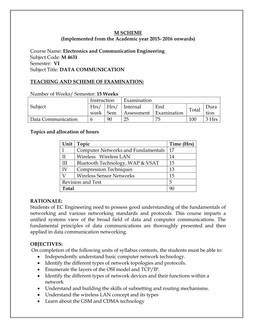
M SCHEME (Implemented from the Academic year 2015- 2016 onwards)
Course Name: Electronics and Communication Engineering Subject Code: M 4631
Semester: VI
Subject Title: DATA COMMUNICATION TEACHING AND SCHEME OF EXAMINATION: Number of Weeks/ Semester: 15 Weeks
Subject
Instruction Examination
Hrs/ week
Hrs/Sem
Internal Assessment
End Examination
Total Duration
Data Communication 6 90 25 75 100 3 Hrs
Topics and allocation of hours
Unit Topic Time (Hrs)
I Computer Networks and Fundamentals 17
II Wireless Wireless LAN 14
III Bluetooth Technology, WAP & VSAT 15
IV Compression Techniques 13
V Wireless Sensor Networks 15
Revision and Test 5
Total 90
RATIONALE: Students of EC Engineering need to possess good understanding of the fundamentals of networking and various networking standards and protocols. This course imparts a unified systems view of the broad field of data and computer communications. The fundamental principles of data communications are thoroughly presented and then applied in data communication networking. OBJECTIVES: On completion of the following units of syllabus contents, the students must be able to:
Independently understand basic computer network technology.
Identify the different types of network topologies and protocols.
Enumerate the layers of the OSI model and TCP/IP.
Identify the different types of network devices and their functions within a network
Understand and building the skills of subnetting and routing mechanisms.
Understand the wireless LAN concept and its types
Learn about the GSM and CDMA technology

Study the Bluetooth and WAP principles
Understand the VSAT technology
Learn different types of data compression techniques
Know the basic concepts of audio compression
Know the basics of wireless sensors
Study the basic concepts of different wireless technologies
M 4631 - DATA COMMUNICATION Unit - I Computer Networks and Fundamentals Introduction to LAN network: Network fundamentals – Applications – Advantages of Networks - Classification of Network based on geographical area (LAN, MAN, WAN) – Network topology – Star – Ring –Mesh – Bus – Tree – Internet and Intranet. Media of Transmission: Open wire – Twisted pair – Coaxial cable – Fiber optic cable Network Hardware: Hub – Ethernet – Bridges –Routers (Principle only) -Data sets and interconnection requirements – classification of modems. OSI Model: Block diagram of OSI Model – Layers – Functions of each layer. TCP / IP: Overview of TCP/IP – OSI & TCP/IP – Transport Layers Protocol– TCP & UDP - Network Layers Protocol – IP – Interior Gateway Protocols (IGMP, ICMP, ARP, RARP Concept only). IP Addressing – Subnetting&Supernetting Unit - II Wireless LAN Introduction to Wireless LANs: Definition – Need – Advantages and Disadvantages of WLAN – Applications of WLAN – Components of Wireless LAN – Types of Wireless LAN – Infrared versus radio transmission – Protocols used in WLAN – Digital Cellular System – GSM – Services and Architecture – Radio Subsystem – CDPD – CDMA – Uses of WLAN HIPERLAN: Introduction – Protocol Architecture. Unit - III Bluetooth Technology, WAP & VSAT Bluetooth: Introduction – Evolution – Need – Bluetooth Radio: Vertical Antenna – Dipole Antenna – Antenna parameters – Ad hoc network – Bluetooth Protocol Architecture – Advantages – Applications – Comparison of wireless LAN and Bluetooth technology. Wireless Access Protocol: Advantages – Services – WAP architecture –Applications. Introduction to VSAT: VSAT Technology – VSAT bands- Components of a VSAT System – Access schemes of VSAT – TDMA – FDMA – CDMA – DAMA – VSAT topology – Advantages and pitfalls - Applications Unit - IV Compression Techniques Data Compression: Coding – Run length encoding - Shannon - Fano Algorithm –
Huffman code- Adaptive Huffman coding – updating – swapping – Overflow –Escape Code – Dictionary based Compression - Encoding and decoding – Static Versus Dynamic Dictionary – Arithmetic Encoding Audio and Video Compression: Fundamentals of digital audio and video Concepts – Lossy and Lossless audio compression (basic principle only) – MP3 Compression –Silence compression – JPEG compression - MPEG compression Unit - V Wireless Sensor Networks (No derivation and Problems – Qualitative treatment only) Wireless Sensor Networks: Definition – Applications of WSN –Advantages and limitations – Wireless Sensor network Architecture –Principle of Hardware and Software subsystems – Wireless technologies – RF tag – Bluetooth (low energy). LoRaWAN – Zigbee and Hotspot (WiMAX) – (basic concepts only) – Comparison BetweenWiFi and WiMax 3G and 4G cellular networks – Protocol structure – principle and advantages – Comparison of 2G, 3G and 4G networks REFERENCE BOOKS: 1. Mobile Communications -Jochen Schiller Pearson Education, New Delhi. 2. Wireless Communication of Networks - William Stallings - PHI 3. BlueTooth - Demystified Nathan J.Muller Tata McGraw – Hill 4. The Data Compression Book, second edition – Mark Nelson and Jean Loup Gailly– BPB publications 5. Wireless Sensor Networks – Technology, Protocol and Applications – Kazem Sohraby, Daniel Minoli and TaiebZnati - John Wiley & Sons, 2007. 6. Computer Networks: Fundamentals and Applications – R.S.Rajesh, K.S. Eswarakumar, R. Balasubramanian

M SCHEME (Implemented from the Academic year 2015- 2016 onwards)
Course Name: Electronics and Communication Engineering
Subject Code: M 4632
Semester: VI
Subject Title: C PROGRAMMING
TEACHING AND SCHEME OF EXAMINATION: Number of Weeks/ Semester: 15 Weeks
Subject
Instruction Examination
Hrs/
week
Hrs/
Sem
Internal
Assessment
End
Examination Total
Dura
tion C Programming 6 90 25 75 100 3 Hrs
Topics and allocation of hours
Unit Topic Time (Hrs)
I Program Development & Introduction to C 17
II Decision Making, Arrays and Strings 14
III Functions , Structures And Unions 15
IV Pointers 14
V File management & Pre-processors 15
Revision and Test 15
Total 90
RATIONALE:
C’ is the most widely used computer language, which is being taught as a core course. C is general purpose structural language that is powerful, efficient and compact, which combines features of high level language and low-level language. It is closer to both Man and Machine. Due to this inherent flexibility and tolerance it is suitable for different development environments. Due to these powerful features, C has not lost its importance and popularity in recently developed and advanced software industry. C can also be used for system level programming and it is still considered as first priority programming language. This course covers the basic concepts of C. This course will act as “Programming concept developer” for students. OBJECTIVES: On completion of the following units of syllabus contents, the students must be able to:
Define Program, Algorithm and flow chart
List down and Explain various program development steps

Write down algorithm and flow chart for simple problems.
Describe the concepts of Constants, Variables, Data types and operators.
Develop programs using input and output operations.
Understand the structure and usage of different looping and branching statements.
Define arrays and string handling functions.
Explain user-defined functions, structures and union.
To understand the dynamic data structure and memory management
To understand the various pointer operations related to C
To learn about the various File handling techniques
M 4632 – C PROGRAMMING UNIT – I Program Development & Introduction to C Program: Program Definition - Program development cycle – Programming Languages – Low Level language – High Level Language – Features of a good programming languages Algorithm and Flow chart: Algorithm – Definition – Properties of an Algorithm –Classification of Algorithms – Algorithm logic - Flow Chart – Importance of Flowchart, Flow chart symbols, Advantages of flow chart – Limitation of flowcharts, Algorithm and flow chart for the following problems: Examples on Algorithms: Area & circumference of circle, to find the product of first n natural numbers , Largest of 3 numbers, Number odd or even, factorial of a given number Introduction to C: History of C - Features of C Language - Structure of a Cprogram– Execution of C Program : - Compiling, Link and Run a program -Diagrammatic representation of program execution process Variables and Constants: C character set - tokens- constants- keywords –identifiers and variables- - data types and storage – data type Qualifiers -Declaration of variables – Assigning values to variables – Escape sequences -defining symbolic constants C operators: Arithmetic, Logical, assignment, relational, increment and decrement, conditional, bit wise, special - operator precedence- C expressions –Arithmetic expressions – evaluation of expressions – type conversions in expressions – type cast operator - operator precedence and associatively I/O statements : Formatted input, formatted output, Unformatted I/O statements UNIT – II Decision Making, Arrays and Strings Decision making and branching: Introduction – simple if statement - if-else -else-if ladder, nested if-else - switch statement - the go to statement – Simple programs Looping Statements: while, do-while statements, for loop, break & continue statement –- simple programs

Arrays: Declaration and initialization of one dimensional, two dimensional and character arrays, accessing array elements. – Programs using arrays Strings: Declaration and initialization of string variables, reading string, writing strings, - string handling functions from standard library (strlen( ), strcpy( ), strcat( ), strcmp( )).- String manipulation programs Unit – III Functions , Structures And Unions Built-in functions: Math functions - console I/O functions - Standard I/O functions - Character Oriented functions - graphical functions – Simple programs User defined Functions: Need of user defined functions, scope and life time of variables, defining functions, function call (call by value, call by reference), return values, storage classes. category of function( No argument No return value, No argument with return value, argument with return value), - Recursion Structures and Unions: Structure - definition, Initialization, Comparison of structure variables, Arrays of Structures, Arrays within structures, Structures with in structures, Structures and functions – Unions – structure of Union- Difference between Union and structure. UNIT – IV Pointers Pointers: Introduction – Advantages of pointers - Accessing the address of a variable, Declaring and initializing pointers, Accessing a variable through its pointer - Pointers expressions, Increments and scale factor - Array of pointers -Relation between Pointers and Arrays - string manipulation using pointers –Limitation of array of pointers to strings - Pointers and functions, Pointers and structures. Dynamic memory Management: Introduction - functions - Memory allocation process – Allocating a block of memory : MALLOC – Allocation of multiple blocks of memory : CALLOC – Releasing the used space: FREE – Altering the size of the block: REALLOC UNIT – V File management & Preprocessors File Management: Introduction – Defining and Opening a file - Closing a file -Input/output operations on files – Error handling during I/O Operations - Random access to files – Programs using files Command line arguments: Introduction – argv and argc arguments – Programs using Command Line Arguments The Preprocessor: Introduction - Macro substitution, File inclusion, Compiler control directives REFERENCE BOOKS 1. Programming in ANSI C E.Balagurusamy Tata Mc-Graw Hill, New Delhi 2. Programming and Problem solving using CISRD Group ,Lucknow Tata Mc-Graw Hill, New Delhi 2010 3. Let us C YeswanthKanetkar BPB Pulications

M SCHEME (Implemented from the Academic year 2015- 2016 onwards)
Course Name: Electronics and Communication Engineering
Subject Code: M 4633
Semester: VI
Subject Title: COMPUTER HARDWARE AND NETWORK
TEACHING AND SCHEME OF EXAMINATION: Number of Weeks/ Semester: 15 Weeks
Subject
Instruction Examination
Hrs/
week
Hrs/
Sem
Internal
Assessment
End
Examination Total
Dura
tion
Computer Hardware And Network
6 90 25 75 100 3 Hrs
Topics and allocation of hours
Unit Topic Time (Hrs)
I Motherboard Components And Memory Storage Devices 17
II I/O Devices And Interface 16
III Maintenance And Trouble Shooting Of Desktop And Laptops 13
IV Computer Network Devices And OSI Layers 15
V 802.X And TCP/IP Protocols 14
Revision and Test 15
Total 90
RATIONALE:
Maintaining and servicing the computers, laptops and peripherals are essential requirements of the computer students. The clear understanding of computer network devices and protocols are also taught in this subject. OBJECTIVES:
On completion of the following units of syllabus contents, the students must be able to:
On completion of the following units of syllabus contents, the students can
Identify the major components of CPU.
Understand the principle of operations of all the interfacing boards, IO/Memory slots and interfacing devices.
Know the use of diagnostic Software.
Trouble shoot the problems in Laptop.

Understand the different layers of OSI and their functions. Compare different LAN protocols.
Identify the protocols used in TCP /IP and compare with OSI model. Use of IP addressing and TCP/ IP protocols briefly
M – 4633 COMPUTER HARDWARE AND NETWORK Unit I - Motherboard Components And Memory Storage Devices Introduction: Parts - Mother board, expansion slots, memory, powersupply, drives and front panel and rear panel connectors – Hardware,Software and Firmware. Processors: Architecture and block diagram of multicore Processor,Features of new processor(Definition only)-chipsets (Concepts only) Bus Standards Overview and features of PCI, AGP, USB,PCMCIA, Processor BUS - High Speed Bus Primary Memory: Introduction-Main Memory, Cache memory –DDR2-DDR3, RAM versions – 1TB RAM – Direct RDRAM Secondary Storage: Hard Disk – Construction – Working Principle –Specification of IDE, Ultra ATA, Serial ATA; HDD Partition - Formatting.Troubleshooting hard disk drives. Removable Storage: CD&DVD construction – reading &writingoperations; CD-R,CD-RW; DVD-ROM, DVD-RW; construction and workingof DVD Reader / Writer.Blue-ray: Introduction – Disc Parameters – Recording and Playback Principles – Solid state memory devices
Unit II - I/O Devices And Interface Keyboard and Mouse: Keyboard: Signals – operation of membraneand mechanical keyboards–troubleshooting; wireless Keyboard. Mousetypes,connectors, operation of Optical mouse and Troubleshooting. Printers: Introduction – Types of printers– Dot Matrix, Inkjet, Laser, lineprinter, MFP (Multi Function Printer), Thermal printer - Operation –Construction – Features and Troubleshooting I/O Ports: Serial, Parallel, USB, Game Port, Bluetooth interface, IRconnector, fire ware, Signal specification problems with interfaces. Displays and Graphic Cards: Panel Displays– Principles of LED, LCDand TFT Displays. VGA and SVGA card. Modem: Working principles – Broadband modems only (USB) -common problems and solutions Power Supply: Servo Stabilizers, online and offline UPS –workingprinciples; Surge suppressors and spike isolators. SMPS: Principles ofOperation and Block Diagram of ATX Power Supply, connectorSpecifications.
Unit III - Maintenance And Trouble Shooting Of Desktop And Laptops Bios-setup: Standard CMOS setup, Advanced BIOS setup, Powermanagement, advanced chipset features, PC Bios communication –upgrading BIOS, Flash BIOS -setup. POST: Definition – IPL hardware – POST Test sequence – beep codesand error messages. Diagnostic Software and Viruses: Computer Viruses – Precautions –Anti-virus Software – identify the signature of viruses – Firewalls and latestdiagnostic software’s. Laptop: Difference between laptop and desktop- Types of laptop –block diagram – working principles–configuring laptops and power settings -SMD components, ESD and precautions. Laptop components: Adapter – types, Battery – types and basicproblems, RAM– types, CPU – types, Laptop Mother Board - block diagram,Laptop Keyboard - Touchpad Installation and Troubleshooting: Formatting, Partitioning andInstallation of OS – Trouble Shooting Laptop Hardware problems -Preventive maintenance techniques for laptops.
Unit IV - Computer Network Devices And OSI Layers Data Communication: Components Of A Data Communication – Dataflow: simplex – half duplex – full duplex; Networks – Definition –Networkcriteria – Types of Connections: Point to point – multipoint; Topologies: Star,Bus, Ring, Mesh, Hybrid – Advantages and Disadvantages of eachtopology. Types of Networks: LAN – MAN – WAN – CAN – HAN – Internet –Intranet –Extranet, Client-Server, Peer To Peer Networks. Transmission Media : Classification of transmission media - Guided –Twisted pair, Coaxial, Fiber optics; Unguided – Radio waves – Infrared –LOS – VSAT – cabling and standards Network devices: Features and concepts of Switches – Routers(Wiredand Wireless) – Gateways. Network Models: Protocol definition - standards - OSI Model – layeredarchitecture – functions of all layers.
Unit V - 802.X And TCP/IP Protocols Overview of TCP / IP: OSI & TCP/IP – Transport Layers Protocol –connection oriented and connectionless Services – Sockets - TCP & UDP. 802.X Protocols : Concepts and PDU format of CSMA/CD (802.3) –Token bus (802.4) – Token ring (802.5) – Ethernet – type of Ethernet (FastEthernet, gigabit Ethernet) – Comparison between 802.3, 802.4 and 802.5 Network Layers Protocol: IP –Interior Gateway Protocols (IGMP,ICMP, ARP, RARP Concept only).

IP Addressing :Dotted Decimal Notation –Subnetting&Supernetting –VLSM Technique-IPv6 (concepts only) Application Layer Protocols: FTP– Telnet – SMTP– HTTP – DNS –POP. REFERENCE BOOKS: 1. IBM PC and CLONES, B.Govindrajalu, Tata McGrawhill Publishers 2. Computer Installation and Servicing, D.Balasubramanian, Tata McGraw Hill 3. Troubleshooting, Maintaining and Repairing PCs, Stephen J Bigelow ,Tata McGraw HillPublication ,Troubleshooting Maintaining and Repairing PCs 4. Upgrading and repairing laptops, Scott Mueller, QUE Publication, Upgrading and repairing laptops 5. Data Communication and networking, BehrouzA.Forouzan, Tata Mc-Graw Hill, New Delhi,

M SCHEME (Implemented from the Academic year 2015- 2016 onwards)
Course Name: Electronics and Communication Engineering
Subject Code: M 464
Semester: VI
Subject Title: EMBEDDED SYSTEM LAB
TEACHING AND SCHEME OF EXAMINATION: Number of Weeks/ Semester: 15 Weeks
Subject
Instruction Examination
Hrs/
week
Hrs/
Sem
Internal
Assessment
End
Examination Total
Dura
tion
Embedded System Lab 4 60 25 75 100 3 Hrs
Allocation of marks
No Allocation Marks
1 Program 35
2 Algorithm / Flowchart 10
3 Execution and Result 25
4 Viva voce 05 Total 75
EQUIPMENTS REQUIRED:
S.
No Name of the Equipments Range
Required
Nos.
1 ARM Processor Trainer Kits LPC 2148 6
2 Add on Boards for interfacing experiments --- Each 1
3 Software – Proteus/ KeilVision ---- (Any 1)

M 464 -EMBEDDED SYSTEM LAB Programs to be performed in Embedded C using Hardware 1. Relay Interface 2. Buzzer Interface 3. Stepper motor Interface (clock wise and counter clock wise) 4. Interface of Seven Segment display 5. Program for Traffic light control 6. LCD interface 7. Program for timer operation using polled method 8. Program for timer operation using Interrupt driven method 9. Program for serial operation 10. Program for ADC operation List of experiments to be conducted using simulation Programs to be performed in ASM 11. Simulation of Arithmetic operations on ARM 12. Simulation of assembly level program for soft delay 13. LED blinking (simple blinking, ring and up counters) 14. I/O operation in ASM 15. Interface with LEDs and Switches using Embedded C Note: Manual containing List of IO registers (SFR for IO) can be given to the students for the End Practical Examination)

M SCHEME (Implemented from the Academic year 2015- 2016 onwards)
Course Name: Electronics and Communication Engineering
Subject Code: M 465
Semester: VI
Subject Title: INDUSTRIAL ELECTRONICS LAB
TEACHING AND SCHEME OF EXAMINATION: Number of Weeks/ Semester: 15 Weeks
Subject
Instruction Examination
Hrs/
week
Hrs/
Sem
Internal
Assessment
End
Examination Total
Dura
tion
Industrial Electronics
Lab 4 60 25 75 100 3 Hrs
Allocation of marks
No Allocation Marks
1 Circuit Diagram 35
2 Connection 10
3 Execution and Equipment handling 15
4 Result and Graph 10
4 Viva voce 05
Total 75
EQUIPMENTS REQUIRED:
S.No
Name of the Equipments Range Required
Nos.
1 DC Regulated power supply 0-30V, 1A 3
2 DC Regulated power supply 0-300V, 1A 1
3 Dual trace CRO 20 MHz / 30MHz 1
4 Digital Multi meter --- 4
5 PLC trainer kits --- 3
6 Add on Boards for PLC experiments --- Each 1
7 Computers for Simulation Experiments --- 3
8 Software – PSPICE / Multi Sim / ORCAD / Tina
--- (Any 1)

M465 -INDUSTRIAL ELECTRONICS PRACTICAL Study Experiments: (Not for Examination)
1. Write and implement a program for CNC lathe involving linear position, circular interpolation and repeat cycle. 2. Write and implement a program for CNC milling for a simple component involving linear position and interpolation.
List of experiments to be conducted using Hardware 1. Determine the phase control characteristics of SCR. 2. Construct and test commutation circuits of SCR. 3. Construct a Lamp dimmer using TRIAC 4. Construct and test a single phase inverter.
5. Construct a phase controlled half (wave ) controlled rectifier using SCR. Plot the output current graph for resistive load. 6. Construct and test Tube light emergency light. 7. Construct and test an IC based buck converter using PWM.
8. Write and implement a simple ladder logic program for interfacing a conveyer control with PLC 9. Industrial sliding door automation - Sequencing - Open ¼ th Full width - Wait for next go command - Next open full - wait for a time and close full 10. Burglar scare random lighting in building with variable timing. The lights in each room are switched on at pre-determined intervalsand switched off at pre-determined time. The lighting is shifted fromarea to area randomly to scare the burglars with a false fear ofpresence of people. List of experiments to be conducted using simulation 11. Construct and draw theV- I characteristics of SCR and find its break over voltage. 12. Construct a circuit to test and plot the V- I characteristics of DIAC and TRIAC.
13. Construct and test the performance of the photo relay using photo transistor. 14. Construct a sequence timer using 555 Timer chip.
15. Write and implement a simple ladder logic program using digital inputs and outputs for PLC

M SCHEME (Implemented from the Academic year 2017- 2018 onwards)
Course Name: Electronics and Communication Engineering
Subject Code: M 4661
Semester: VI
Subject Title: ROBOTICS LAB
TEACHING AND SCHEME OF EXAMINATION: Number of Weeks/ Semester: 15 Weeks
Subject
Instruction Examination
Hrs/
week
Hrs/
Sem
Internal
Assessment
End
Examination Total
Dura
tion
Robotics Lab 4 60 25 75 100 3 Hrs
Allocation of marks
No Allocation Marks
1 Circuit Diagram 30
2 Procedure 10
3 Execution and Equipment Handling 25
4 Result 05
5 Viva voce 05
Total 75
EQUIPMENTS REQUIRED:
S.No
Name of the Equipments Required
Nos.
1 Robotic Kits (AVR / ARM / 8051 ) 6 Nos
2 Add on Boards for interfacing Each 1
3 Desktop / Laptop 6
M4661 – ROBOTICS LAB
Programs using AVR / ARM /8051 controller for robotics:
1. LED blinking
2. Forward and backward motion control
3. Left and right motion
4. Circular motion control
5. Buzzer interfacing
6. Relay interfacing
7. LCD
8. ADC sensor interfacing
9. Servo motor interfacing
10. Gripper [ pick and place]
11. Line follower
12. Velocity Control

M SCHEME (Implemented from the Academic year 2015- 2016 onwards)
Course Name: Electronics and Communication Engineering
Subject Code: M 4662
Semester: VI
Subject Title: CPROGRAMMING LAB
TEACHING AND SCHEME OF EXAMINATION: Number of Weeks/ Semester: 15 Weeks
Subject
Instruction Examination
Hrs/
week
Hrs/
Sem
Internal
Assessment
End
Examination Total
Dura
tion
C Programming Lab 4 60 25 75 100 3 Hrs
Allocation of marks
No Allocation Marks
1 Writing Program 35
2 Algorithm / Flowchart 10
3 Execution and Result 25
4 Viva voce 05
Total 75
EQUIPMENTS REQUIRED:
S.
No Name of the Equipments Range
Required
Nos.
1 Desktops and Laptops ---- 6
2 Laser Printer ---- 1
3 Software (C Compiler and Editor) ---- 1

M 4662 - C PROGRAMMING LAB
List of experiments to be conducted 1. Write a C Program to calculate Simple and Compound interest 2. Write C language program to find the solution of a quadratic equation. 3. Write C language program to find whether the given number is a positive number, negative number or zero. 4. Write C language program to find the sum of series using While loop. 5. Write C language program to perform the Arithmetic operation based on the numeric key press using switch case statement. (1-Addition, 2-Subtraction, 3 – multiplication, 4 - Division). 6. Write C language program to implement Ohms Law. 7. Write C language program to find factorial of given N numbers using function. 8. Write C language program to prepare the total marks for N students by reading the Name, Reg.No, Marks 1 to Marks 6 using array of structure. 9. Write C language program to swap the values of two variables. 10. Read a string, which consists of both lower case characters and upper case characters. Convert the lowercase character into upper case and vice versa. Display the new string. 11. Write a function to calculate the sum and average of given three numbers. Write a main function to call the above function 12. Using pointers, find the length of the given string. 13. Write a program to read an integer number and find the sum of all individual digits. 14. Write a program to arrange the given N names in alphabetical order. 15. Program to copy contents of one file to another file. Also find the number of characters, lines and words in the above file
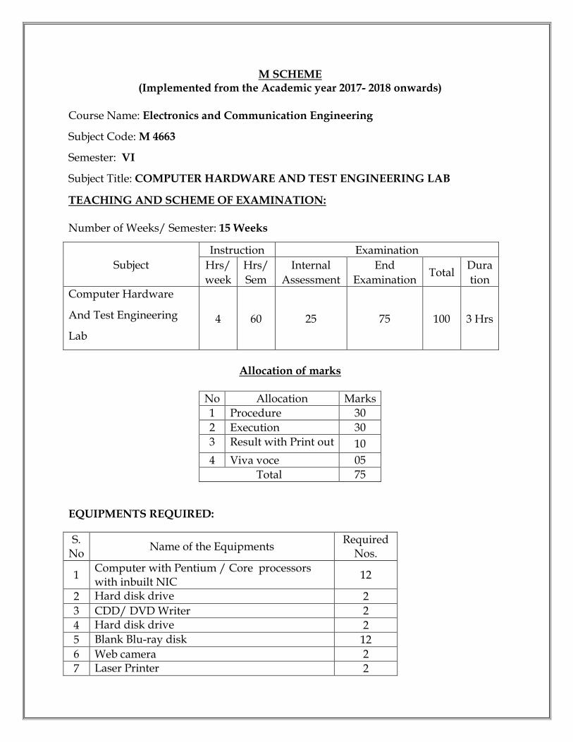
M SCHEME (Implemented from the Academic year 2017- 2018 onwards)
Course Name: Electronics and Communication Engineering
Subject Code: M 4663
Semester: VI
Subject Title: COMPUTER HARDWARE AND TEST ENGINEERING LAB
TEACHING AND SCHEME OF EXAMINATION: Number of Weeks/ Semester: 15 Weeks
Subject
Instruction Examination
Hrs/
week
Hrs/
Sem
Internal
Assessment
End
Examination Total
Dura
tion Computer Hardware
And Test Engineering
Lab
4 60 25 75 100 3 Hrs
Allocation of marks
No Allocation Marks
1 Procedure 30
2 Execution 30
3 Result with Print out 10
4 Viva voce 05
Total 75
EQUIPMENTS REQUIRED:
S.No
Name of the Equipments Required
Nos.
1 Computer with Pentium / Core processors with inbuilt NIC
12
2 Hard disk drive 2
3 CDD/ DVD Writer 2
4 Hard disk drive 2
5 Blank Blu-ray disk 12
6 Web camera 2
7 Laser Printer 2
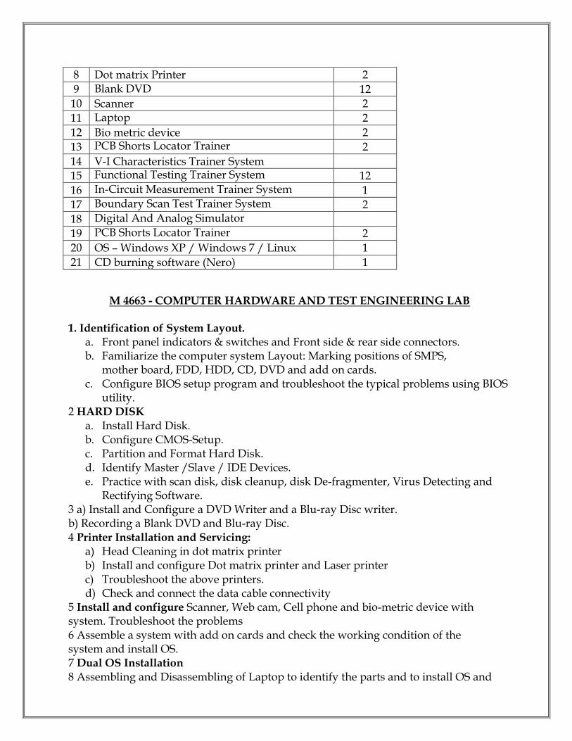
8 Dot matrix Printer 2
9 Blank DVD 12
10 Scanner 2
11 Laptop 2
12 Bio metric device 2
13 PCB Shorts Locator Trainer 2
14 V-I Characteristics Trainer System
15 Functional Testing Trainer System 12
16 In-Circuit Measurement Trainer System 1
17 Boundary Scan Test Trainer System 2
18 Digital And Analog Simulator
19 PCB Shorts Locator Trainer 2
20 OS – Windows XP / Windows 7 / Linux 1
21 CD burning software (Nero) 1
M 4663 - COMPUTER HARDWARE AND TEST ENGINEERING LAB 1. Identification of System Layout.
a. Front panel indicators & switches and Front side & rear side connectors. b. Familiarize the computer system Layout: Marking positions of SMPS,
mother board, FDD, HDD, CD, DVD and add on cards. c. Configure BIOS setup program and troubleshoot the typical problems using BIOS
utility. 2 HARD DISK
a. Install Hard Disk. b. Configure CMOS-Setup. c. Partition and Format Hard Disk. d. Identify Master /Slave / IDE Devices. e. Practice with scan disk, disk cleanup, disk De-fragmenter, Virus Detecting and
Rectifying Software. 3 a) Install and Configure a DVD Writer and a Blu-ray Disc writer. b) Recording a Blank DVD and Blu-ray Disc. 4 Printer Installation and Servicing:
a) Head Cleaning in dot matrix printer b) Install and configure Dot matrix printer and Laser printer c) Troubleshoot the above printers. d) Check and connect the data cable connectivity
5 Install and configure Scanner, Web cam, Cell phone and bio-metric device with system. Troubleshoot the problems 6 Assemble a system with add on cards and check the working condition of the system and install OS. 7 Dual OS Installation
8 Assembling and Disassembling of Laptop to identify the parts and to install OS and

configure it. 9 Do the following Cabling works in a network a) Cable Crimping b) Standard Cabling c) Cross Cabling d) IO connector crimping e) Testing the crimped cable using a cable tester 10. Locate a Short in a circuit Board using Short Locator.
11.Test and verify the combinational logic circuits NAND, NOR, Half adder, Half subtractors, Multiplexers, De-multiplexer, Decoder & Encoder using functional test method.
12.Test and verify the Sequential Logic Circuits D-FF, RS-FF, Latch, Counter, Shift Register using functional test method.
13.Test and verify the Memory Devices SDRAM/DRAM Chip using functional test method.
14. a. Test and verify the digital circuits in a circuit using auto compensation technique. b. Test and verify the open emitter circuit using pull down resistor. c. Test and verify the open collector circuit using pull up resistor.
15. Test the functionality of operational amplifier in Inverting, Non-inverting and voltage follower mode.

M SCHEME (Implemented from the Academic year 2015- 2016 onwards)
Course Name: Electronics and Communication Engineering
Subject Code: M 467
Semester: VI
Subject Title: PROJECT WORK
TEACHING AND SCHEME OF EXAMINATION:
Number of Weeks/ Semester: 15 Weeks
Subject
Instruction Examination
Hrs/
week
Hrs/
Sem
Internal
Assessment
End
Examination Total
Dura
tion
Project Work 6 90 25 75 100 3 Hrs
OBJECTIVES:
Implement the theoretical and practical knowledge gained through the curriculum into an application suitable for a real practical working environment preferably in an industrial environment
Get exposure on industrial environment and its work ethics. Understand what entrepreneurship is and how to become an entrepreneur.
Learn and understand the gap between the technological knowledge acquired through curriculum and the actual industrial need and to compensate it by acquiring additional Knowledge as required.
Carry out cooperative learning through synchronous guided discussions within the class in key dates, asynchronous document sharing and discussions, as well as to prepare collaborative edition of the final project report.
Understand the facts and importance of environmental management. Understand and gain knowledge about disaster management.
M 467 PROJECT WORK
ENVIRONMENTAL & DISASTER MANAGEMENT 1. ENVIRONMENTAL MANAGEMENT Introduction – Environmental Ethics – Assessment of Socio Economic Impact – Environmental Audit – Mitigation of adverse impact on Environment – Importance of Pollution Control – Types of Industries and Industrial Pollution. Solid waste management – Characteristics of Industrial wastes – Methods of Collection, transfer and disposal of solid wastes – Converting waste to energy – Hazardous waste management Treatment technologies.
Waste water management – Characteristics of Industrial effluents – Treatment and disposal methods – Pollution of water sources and effects on human health. Air pollution management – Sources and effects – Dispersion of air pollutants – Air pollution control methods – Air quality management. Noise pollution management – Effects of noise on people – Noise control methods. 2. DISASTER MANAGEMENT Introduction – Disasters due to natural calamities such as Earthquake, Rain, Flood, Hurricane, Cyclones etc – Man made Disasters – Crisis due to fires, accidents, strikes etc – Loss of property and life.. Disaster Mitigation measures – Causes for major disasters – Risk Identification – Hazard Zones – Selection of sites for Industries and residential buildings – Minimum distances from Sea – Orientation of Buildings – Stability of Structures – Fire escapes in buildings -Cyclone shelters – Warning systems. Disaster Management – Preparedness, Response, Recovery – Arrangements to be made in the industries / factories and buildings – Mobilization of Emergency Services -Search and Rescue operations – First Aids – Transportation of affected people – Hospital facilities – Fire fighting arrangements – Communication systems – Restoration of Power supply – Getting assistance of neighbors / Other organizations in Recovery and Rebuilding works – Financial commitments – Compensations to be paid – Insurances –Rehabilitation. LIST OF QUESTIONS A. ENVIRONMENTRAL MANAGEMENT
1. What is the responsibility of an Engineer-in-charge of an Industry with respect to Public Health?
2. Define Environmental Ethic. 3. How Industries play their role in polluting the environment? 4. What is the necessity of pollution control? What are all the different organizations
you know, which deal with pollution control? 5. List out the different types of pollutions caused by a Chemical / Textile / Leather
/ Automobile / Cement factory. 6. What is meant by Hazardous waste? 7. Define Industrial waste management. 8. Differentiate between garbage, rubbish, refuse and trash based on their
composition and source. 9. Explain briefly how the quantity of solid waste generated in an industry could be
reduced. 10. What are the objectives of treatments of solid wastes before disposal? 11. What are the different methods of disposal of solid wastes?
B. DISASTER MANAGEMENT

1. What is meant by Disaster Management? What are the different stages of Disaster management?
2. Differentiate Natural Disasters and Man made Disasters with examples. 3. Describe the necessity of Risk identification and Assessment Surveys while
planning a project. 4. What is Disasters recovery and what does it mean to an Industry? 5. What are the factors to be considered while planning the rebuilding works after a
major disaster due to flood / cyclone / earthquake? (Any one may be asked) 6. List out the public emergency services available in the state, which could be
approached for help during a natural disaster. 7. Specify the role played by an Engineer in the process of Disaster management. 8. What is the cause for Earthquakes? How they are measured? Which parts of India
are more vulnerable for frequent earthquakes? 9. What was the cause for the Tsunami 2004 which inflicted heavy loss to life and
property along the coast of Tamilnadu? Specify its epicenter and magnitude. 10. Specify the Earthquake Hazard Zones in which the following towns of Tamil
Nadu lie: (a) Chennai (b) Nagapattinam (c) Coimbatore (d) Madurai (e) Salem.
11. Which parts of India are experiencing frequent natural calamities such as (a) heavy rain fall (b) huge losses due to floods (c) severe cyclones
************
