sanitary sewer mains and services - brookings utilities sewer mains and services sewer table of...
TRANSCRIPT

Sewer Title
STitle (605) 692-6325 Brookings Municipal Utilities
Sanitary Sewer Mains
and Services
Sewer Table of Contents
STable (605) 692-6325 Brookings Municipal Utilities
"CORRECTIVE PERIOD & INSPECTION FOR SANITARY SEWERS & SERVICES" ............... 1 1. TERM OF GUARANTEE ................................................................................................................. 1 2. CONTRACTOR LICENSE AND PERMITS .................................................................................... 1 3. INSPECTION OF SANITARY SEWER MAINS & SERVICES ..................................................... 1 4. ELEVATION DATUM ..................................................................................................................... 1 5. PROJECT DESIGN CHANGES ....................................................................................................... 1 6. CERTIFICATE OF SUBSTANTIAL COMPLETION ..................................................................... 2
"MATERIAL SPECIFICATIONS FOR SANITARY SEWERS & SERVICES" ............................... 4 7. SCOPE OF WORK ............................................................................................................................ 4 8. MATERIAL INSPECTION ............................................................................................................... 4 9. MATERIAL HANDLING & STORAGE .......................................................................................... 4 10. AGGREGATE MATERIALS ........................................................................................................ 4 11. WATER/SEWER TAPPING FEES ............................................................................................... 5 12. POLYVINYL CHLORIDE (PVC) PIPE, SDR 35 (4"-48”) .......................................................... 6 13. POLYVINYL CHLORIDE (PVC) PIPE, SDR 26 (4"-48”) .......................................................... 6 14. POLYVINYL CHLORIDE (PVC) PIPE & FITTINGS, DR 25 or Class 100 (4"-12”) ................. 6 15. DUCTILE-IRON PIPE (DIP) ......................................................................................................... 7 16. MANHOLE .................................................................................................................................... 7 17. PIPE TO WALL PENETRATION SEALS ON EXISTING MANHOLES ................................ 10
"CONSTRUCTION SPECIFICATIONS FOR SANITARY SEWERS & SERVICES" ................... 11 18. ALIGNMENT AND GRADE ...................................................................................................... 11 19. UNDERGROUND INTERFERENCE ......................................................................................... 11 20. MANUAL ON UNIFORM TRAFFIC CONTROL DEVICES ................................................... 11 21. WATER MAIN AND SANITARY SEWER MAIN SEPARATION .......................................... 12 22. JOB SITE AND WORK AREA CLEANUP................................................................................ 13 23. CASING PIPE UNDER HIGHWAYS, RAILROADS, ETC. ..................................................... 13 24. DEWATERING ........................................................................................................................... 13 25. ABANDONED SANITARY SEWER MAIN AND MANHOLES ............................................. 13 26. TRENCH CONSTRUCTION ...................................................................................................... 14 27. PIPE INSTALLATION ................................................................................................................ 16 28. JOINT ASSEMBLY ..................................................................................................................... 17 29. BACKFILLING ........................................................................................................................... 17 30. FITTING INSTALLATION ........................................................................................................ 18 31. SANITARY SEWER SERVICES (4"-6”) ................................................................................... 19
“SANITARY SEWER MAIN TESTING AND INSPECTION” .......................................................... 21 32. TELEVISED INSPECTION OF SANITARY SEWER MAIN ................................................... 21 33. GRAVITY SANITARY SEWER MAIN AIR TEST .................................................................. 21 34. SANITARY SEWER FORCEMAIN HYDROSTATIC PRESSURE TESTING ........................ 22 35. INFILTRATION TESTING SANITARY SEWER MAIN ......................................................... 23 36. EXFILTRATION TESTING SANITARY SEWER MAIN ........................................................ 23 37. DEFLECTION TESTING SANITARY SEWER MAIN ............................................................. 24 38. MANHOLE TESTS ..................................................................................................................... 24
“SEWER INSTALLATION DETAILS” .......................................................................... SDetails-1 to 11
revised: 02/28/2013 Sanitary Sewer Specifications
Sanitary Sewer Specifications-1 of 27 (605) 692-6325 Brookings Municipal Utilities
"CORRECTIVE PERIOD & INSPECTION FOR SANITARY SEWERS & SERVICES"
1. TERM OF GUARANTEE
a. Corrective Period: The corrective period shall cover the contract as to workmanship and materials for a period of five (5) years in compliance with the City of Brookings ordinance "Excavating & Backfilling on Public Right-of-Way". The corrective period of five (5) years shall commence from the BMU determined Substantial Completion date.
b. Responsibility: The Contractor shall be held responsible for workmanship, materials, settling trenches or any other deficiencies in the sewer main system during the corrective period. The Contractor shall repair and/or replace all deficiencies in the sewer system during the five (5) year corrective period at no cost to the Owner. Any surface restoration costs incurred because of the repairing and/or replacing of deficiencies in the sewer system shall be borne by the Contractor.
2. CONTRACTOR LICENSE AND PERMITS
a. License: The Contractor shall be required to have any required licenses (sewer
and water installation Contractor license or sewer and water installer license) for water/sewer installation or water/sewer repairing as stated in the South Dakota State Plumbing Code.
b. Excavation Permit: The Contractor shall obtain an “excavation permit” issued at no charge from the Brookings City Engineering Office (520 Third Street) before any water/sewer installation or water/sewer repairing will be allowed.
c. Dewatering Permit: The Contractor shall obtain any “dewatering permits” required from local, state or federal agencies. The Contractor shall submit a copy of the dewatering permit to BMU prior to dewatering. The discharge area must be prior approved by the Engineer before initiating the dewatering.
3. INSPECTION OF SANITARY SEWER MAINS & SERVICES
a. Engineer Inspection: The Engineer or Engineers’ Representative shall have
access at all times to all parts of the job and the Contractor must furnish all such facilities and materials which are necessary to make whatever tests and inspections that are deemed necessary. The Engineer reserves the right to inspect and/or reject any part of, or all unsatisfactory work performed by the Contractor. Rejected or unapproved work shall not be paid for.
4. ELEVATION DATUM
a. Elevation Datum: The Project Designer shall utilize only a City Engineer
approved NAVD 88 datum for elevation reference. The Project Designer shall bring elevation control to the project site, preferably a nearby fire hydrant. All elevations established on hydrants shall be on top of the “O” on open (facing nozzle) with a tolerance of 0.03’ or less. The City Engineer approved NAVD 88 datum and all project site elevation controls are to be noted on the plan sheets.
5. PROJECT DESIGN CHANGES
a. Project Design Changes: If the Owner or the Owners’ Designer make any project
design changes after the sewer main, sewer apparatus or sewer services have been purchased or installed, the location or elevation changes required for the sewer main, sewer apparatus or sewer services shall be at the Owners’ expense.

revised: 02/28/2013 Sanitary Sewer Specifications
Sanitary Sewer Specifications-2 of 27 (605) 692-6325 Brookings Municipal Utilities
6. CERTIFICATE OF SUBSTANTIAL COMPLETION DATE OF ISSUANCE:
OWNER: Brookings Municipal Utilities
CONTRACTOR:
Project:
BMU Project No: BMU Work Order No:
Contract Dated: (applicable only to BMU funded projects)
This Certificate of Substantial Completion applies to all Work under the Contract Documents or to the following specified parts thereof: To: Brookings Municipal Utilities OWNER And To: CONTRACTOR The Work to which this Certificate applies has been inspected by authorized Representatives of OWNER and the CONTRACTOR, and that Work is hereby declared to be substantially complete in accordance with the Contract Documents on: BMU Determined Substantial Completion Date Five (5) Years Corrective Period in Years Corrective Period Expiration Date

revised: 02/28/2013 Sanitary Sewer Specifications
Sanitary Sewer Specifications-3 of 27 (605) 692-6325 Brookings Municipal Utilities
The CONTRACTOR accepts this Certificate of Substantial Completion and accepts corrective period responsibilities. Date: (Contractor) (Company Name) Date: Brookings Municipal Utilities (Project Superintendent) (Company Name) Date: Brookings Municipal Utilities (Utility Operations Manager) (Company Name) SUBSTANTIAL COMPLETION APPROVED Date: Brookings Municipal Utilities (Executive Vice President (Company Name) & General Manager)
revised: 02/28/2013 Sanitary Sewer Specifications
Sanitary Sewer Specifications-4 of 27 (605) 692-6325 Brookings Municipal Utilities
"MATERIAL SPECIFICATIONS FOR SANITARY SEWERS & SERVICES"
7. SCOPE OF WORK
The Contractor shall furnish all materials (except for Utility furnished materials), equipment and labor necessary to install sewer main as per plans and specifications. It is the intent of these specifications to install a complete sewer system; and the Contractor shall furnish everything necessary to do this, whether or not all items are specifically called for in these plans and/or specifications.
8. MATERIAL INSPECTION
a. Material Inspection: All pipe and appurtenances are subject to inspection by the
Engineer. Material found to be defective due to manufacture or damage in shipment shall be rejected and removed from the job site.
b. Material Testing: The Engineer may perform tests to ensure conformance with the sewer standard. In case of failure of the pipe or appurtenance to comply with such specifications, responsibility for replacement of the defective materials becomes that of the Contractor or Manufacturer, even if piping and appurtenance has already been installed.
9. MATERIAL HANDLING & STORAGE
a. Material Handling: All pipe, fittings, and accessories shall be loaded and
unloaded by a means to prevent shock or damage. Under no circumstances shall such material be dropped.
b. Material Storage: Materials, if stored, shall be kept safe from damage. The interior of all pipe, fittings, and other appurtenances shall be kept free from dirt or foreign matter at all times.
c. Pipe: Piping shall not be stacked higher than Manufacturers’ recommendations according to size. The bottom tier of piping shall be kept off the ground on timbers, rails, or concrete. Pipe in tiers shall be alternated: bell, plain end; plain end, bell. At least two rows of timbers shall be placed between tiers, and chocks shall be affixed to each timber in order to prevent movement. The timbers shall be large enough to prevent contact between the pipes in adjacent tiers.
d. Gaskets: Gaskets for push-on joints shall be stored in a cool location, out of direct sunlight. Gaskets shall not come in contact with petroleum products. Gaskets shall be used on a first-in, first-out basis.
10. AGGREGATE MATERIALS
a. Trench Stabilization Material (#4 Ballast or 1½”x ¾” Rock): The Contractor
shall be required to use a trench stabilization material, as directed by the Engineer, if the sub-grade is deemed unstable. The stabilization material, unless otherwise directed, shall conform to the following sieve analysis: #4 Ballast Percentage by weight
sieve size passing through sieve 2 ½ inch 100% 2 inch 90% to 100% 1 ½ inch 50% to 80% 1 inch 10% to 35% ¾ inch 0% to 10% ½ inch 0% to 5%

revised: 02/28/2013 Sanitary Sewer Specifications
Sanitary Sewer Specifications-5 of 27 (605) 692-6325 Brookings Municipal Utilities
1 ½”x ¾” Rock Percentage by weight
sieve size passing through sieve 2 inch 100% 1 ½ inch 50% to 100% 1 inch 5% to 55% ¾ inch 0% to 15%
a. Pipe Bedding Material (3/8”x 1/8” Pearock): The Contractor shall be required to use the following for pipe bedding. The pipe bedding to use, unless otherwise directed, shall conform to the following sieve analysis: 3/8”x 1/8” Pearock Percentage by weight
sieve size passing through sieve 3/8 inch 95% to 100% #4 10% to 90% #8 0% to 30% #40 0% to 4%
b. Road Topping or Trench Replacement Material (3/4” Crushed Gravel): Trench replacement in developed streets, or if there is a deficiency due to a rejection of a part thereof, shall be 3/4” crushed gravel with a soil mortar or binder, unless otherwise directed. The crushed gravel shall conform to the South Dakota Department of Transportation Specifications, Section 882 “Aggregates for Granular Bases and Surfacing”. The 3/4” crushed gravel, unless otherwise directed, shall conform to the following sieve analysis: 3/4” Crushed Gravel Percentage by weight
sieve size passing through sieve 1 inch 100% ¾ inch 80% to 100% ½ inch 68% to 91% #4 46% to 70% #8 34% to 58% #40 13% to 35% #200 3% to 12%
11. WATER/SEWER TAPPING FEES
a. Water Tapping Fees & Corporations: After the Contractor pays the water tapping fee, the city shall furnish & install all corporations with saddle up to and including 2" corporations. A water service 2" or larger shall require prior Utility approval.
1” water tapping fee: $147.00 1 1/2” water tapping fee: $211.00 2” water tapping fee: $344.00
b. Curb Stops: All curb stops with 4” PVC sidewalk casings shall be furnished and installed by the Contractor. 4” PVC curb stop casing shall be ASTM D3034, and shall have an SDR 35 rating, and shall be cut longer than the sidewalk thickness. (Copper rolls over 1” are 60’ lengths, 100’ lengths take +/-10 weeks to get, no splices allowed)
c. Sewer Tapping Fees: After the Contractor pays the sewer tapping fee, the city shall furnish & install inserta tees or saddles for making sewer taps. If the Contractor installs an in-line wye, inserta tee, or a saddle, then a tapping fee would not be required.
4” & 6” sewer tapping fee: $87.00

revised: 02/28/2013 Sanitary Sewer Specifications
Sanitary Sewer Specifications-6 of 27 (605) 692-6325 Brookings Municipal Utilities
12. POLYVINYL CHLORIDE (PVC) PIPE, SDR 35 (4"-48”)
a. PVC Sewer Pipe: 4"-15" PVC sewer pipe shall conform to the latest revision of ASTM D3034. 18” PVC & larger shall conform to the latest revision of F-679. Schedule 40 PVC shall be required for sewer services where the water service is in the same trench and the water service is not shelved above the sewer service, see “sewer details”.
b. PVC Sewer Pipe Joints: PVC sewer pipe shall have rubber-gasket joints conforming to the latest revision of ASTM D3212 & ASTM F-477.
c. PVC Sewer Pipe Couplers: PVC sewer pipe couplers shall be “strong back” or no-sheer” type, or an approved equal.
13. POLYVINYL CHLORIDE (PVC) PIPE, SDR 26 (4"-48”) (for service risers, directional boring, hole hogging and main depths exceeding 20' of cover)
a. PVC Sewer Pipe: 4"-15" PVC sewer pipe shall conform to the latest revision of
ASTM D3034. 18” PVC & larger shall conform to the latest revision of F-679. b. PVC Sewer Service Risers: Sewer service risers are to be prior approved by the
Owner and/or the Engineer. Sewer service risers shall be required when the sewer main invert is 14’-0” or more to the proposed road grade. Elevations for an approved sewer service riser shall be determined by the Engineer and/or the Owner. 4"-6" PVC sewer service risers shall conform to the latest revision of ASTM D3034. The in-line wye shall be required to have the same SDR rating as the sewer main, but the sewer service riser shall be required to be SDR 26 until the sewer service is 5’ (min) onto virgin ground. After the sewer service is installed 5’ (min) onto virgin ground, the sewer service may revert to ASTM D3034 with an SDR 35 rating, unless otherwise specified. Rock ballast may be required from the center of the carrier sewer main up to where the sewer service riser is anchored to the virgin soil. This is to ensure the sewer service shall be stable when backfilling.
c. PVC Sewer Services via Directional Boring or Hole Hogging: Sewer services installed via directional boring or hole hogging are to be prior approved by the Owner and/or the Engineer. Directional boring or hole hogging for a sewer service line will not be allowed for sewer services with grades less than 2.00%. 4"-6" PVC sewer services installed via directional boring or hole hogging shall conform to the latest revision of ASTM D3034. Such shall be from one end of the directional bore or hole hog to the other end of the directional bore or hole hog. On either side of the directional bore or hole hog the sewer service may be reverted to ASTM D3034 with an SDR 35 rating, unless otherwise specified.
d. PVC Sewer Pipe Joints: PVC sewer pipe shall have rubber-gasket joints conforming to the latest revision of ASTM D3212 & ASTM F-477.
e. PVC Sewer Pipe Couplers: PVC sewer pipe couplers shall be “strong back” or no-sheer” type, or an approved equal.
14. POLYVINYL CHLORIDE (PVC) PIPE & FITTINGS, DR 25 (4"-12”)
(water main pipe used for sewer forcemain)
a. PVC Water Pipe: PVC pipe and fittings shall conform to the latest revision of the AWWA C900 (4"-12") standard or the latest revision of the AWWA C905 (14"-36") standard. PVC pipe and fittings shall have a Cast Iron Pipe (CIP) outside diameter.
b. PVC Fittings: PVC fittings shall be polyvinyl chloride (PVC) pressure fittings and shall conform to the ANSI/AWWA C907 (4”-8”) standard. PVC fittings shall have a Cast Iron Pipe (CIP) outside diameter.

revised: 02/28/2013 Sanitary Sewer Specifications
Sanitary Sewer Specifications-7 of 27 (605) 692-6325 Brookings Municipal Utilities
c. DIP Fittings: DIP fittings shall be push-on joint or mechanical joint fittings and
shall conform to the latest revision of the ANSI/AWWA C110/A21.10 (3"-48") standard or the latest revision of the ANSI/AWWA C153/A21.53 (3"-24" & 54”-64”) standard for compact fittings. DIP fittings shall have a Cast Iron Pipe (CIP) outside diameter. DIP & fittings shall be cement lined conforming to the latest revision of the ANSI/AWWA C104/A21.4 standard. Rubber-gasket joints for DIP & fittings shall conform to the latest revision of the ANSI/AWWA C111/A21.11 standard.
d. PVC Water Pipe Joints: PVC pipe and PVC fittings shall have rubber-gasket joints which conform to the latest revision of the ANSI/AWWA C111/A21.11 standard.
e. Valves & Valve Boxes: Valves, gaskets and bolts, valve box adaptors, and valve boxes with metallic inserts which have a cast iron drop cover will be furnished by the city and installed by the Contractor.
15. DUCTILE-IRON PIPE (DIP) (for elevated sewer stubs on drop manholes)
a. Ductile-Iron Pipe (DIP): The DIP, push-on joint or mechanical joint, shall
conform to the latest version of the ANSI/AWWA C151/A21.51 (3"-64") standard. DIP and fittings shall have a minimum Pressure Class of 150.
b. DIP Fittings: Fittings shall be ductile-iron push-on joint or mechanical joint fittings and shall conform to the ANSI/AWWA C110/A21.10 (3"-48") standard or the ANSI/AWWA C153/A21.53 (3"-24" & 54”-64”) standard for compact fittings. Fittings shall have a minimum Pressure Class of 150.
c. Cement-Mortar Lining for Ductile-Iron Pipe and Fittings for Water: DIP & fittings shall be cement lined conforming to the latest version of the ANSI/AWWA C104/A21.4 standard.
d. Rubber-Gasket Joints for Ductile-Iron Pressure Pipe and Fittings: Rubber-gasket joints for DIP & fittings shall conform to the latest version of the ANSI/AWWA C111/A21.11 standard.
16. MANHOLE
a. Precast Concrete Manhole Specifications: Precast concrete manholes shall
conform to the latest revision of ASTM C478. All manholes for new construction to be monolithically poured structures. Upon request from the Engineer, the Contractor and/or supplier shall supply the Engineer with a test report from an independent testing laboratory showing compliance with the ASTM C478 standard. All manholes shall be constructed without steps or ladders. Manholes are to be constructed according to the dimensions shown on the plan sheets or from staking sheets provided by the Engineer. The Contractor shall provide shop drawings of the manhole details from his vendor for Utility records, not for approval. This shall be done prior to the construction of the manholes.
b. Standard Manhole: Standard manholes shall have an inside diameter of 48" unless otherwise stated in the plans and/or specifications.
c. Distances between Manholes: Distances between manholes shall be determined by the Engineer (BMU equipment can jet clean up to 550’ in length) with manhole locations in the centerline of future lateral right-of-ways where applicable.
d. Outside Drop Manholes: Outside drop manholes are not allowed, if a drop is required see “Inside Drop Manholes”.

revised: 02/28/2013 Sanitary Sewer Specifications
Sanitary Sewer Specifications-8 of 27 (605) 692-6325 Brookings Municipal Utilities
e. Inside Drop Manholes: Manholes with inside drops shall be required if the drop
exceeds 2.00' between the highest inlet invert and 80% of the inside diameter of the pipe added to the invert of the bottom carrier pipe. Inside drop manholes shall have an inside diameter of 48" unless otherwise stated in the plans and/or specifications. All inside drops shall be a Reliner by Duran Inc. inside drop system, or an approved equal. The “A” size drop bowl has a 12” wide receptor bowl with a 4” or 6” outlet. The 4” bowl outlet will service a 6” sewer main and the 6” bowl outlet will service an 8” sewer main. The “B” size drop bowl has an 18” wide receptor bowl with an 8” or 10” outlet. The 8” bowl outlet will service a 10” sewer main and the 10” bowl outlet will service a 12” sewer main. For larger than 10” sewer main drops consult with the Engineer. The bowl shall be fastened securely with 304 stainless steel fasteners. The sewer main inlet shall protrude through the manhole to the edge of the drop in the bowl, where the Contractor shall make a 1 ¼” long 60-90 degree v-notch in the bottom of the sewer main inlet. The PVC drop section shall be secured to the barrel section with Reliner brand 304 stainless steel adjustable clamping, or an approved equal. Clamps shall be required 6” maximum from the bottom 45 degree solvent weld elbow and 6” maximum from the drop bowl, with 4’-0” maximum spacing between clamps. A 45 degree bend shall be installed on the bottom of the drop to direct the flow towards the channel. The 304 stainless steel fasteners shall not be allowed to penetrate the precast manhole section. Ductile-iron piping shall be required for all elevated sewer stubouts from the manhole to 5' (min) into virgin soil.
f. Eccentric Cone Section: The upper precast cone section of the manhole shall be eccentric (offset) and shall have a 24" minimum to a 27" (preferred) maximum diameter opening at the top unless otherwise stated in the plans and/or specifications. The opening (flat side) of the eccentric cone section shall be positioned over the outflow side of the carrier pipe unless otherwise stated or directed.
g. Joint Sealant: A flexible butyl rubber joint sealant shall be used between manhole sections and concrete adjusting rings for creating a water tight sealant. Ramnek, Kentseal, Conseal or other approved flexible butyl rubber joint sealant shall be used. Rubber gaskets and joints meeting the requirements of ASTM C443, C361 and the Bureau of Reclamation R-4 specifications shall also be accepted for manhole joints.
h. Pipe Stubouts from Manhole: All sewer main stubouts shall be 13’ (one length of pipe), unless otherwise directed, and shall be considered part of the manhole construction.
i. Resilient Connectors: Resilient connectors between precast concrete manholes and sewer main pipe shall conform to the latest revision of ASTM C923, providing a watertight connection.
j. Manhole Piping & Resilient Connector Elevations: All manholes accommodating PVC sewer mains larger than 8" in diameter shall be pushed through the manhole and through the opposite resilient connector when applicable. If the opposite resilient connector is to high to achieve this, then the PVC piping shall be pushed through the manhole to the opposite wall of the manhole. The same shall apply to manholes with PVC sewer mains 8" in diameter unless the lateral sewer main inverts are lower than 80% of the inside diameter of the carrier pipe added to the invert of the carrier pipe. In this case pushing the pipe through the manhole will not be required. When a manhole accommodates two different sized sewer pipes, the 80% flow depth elevation of the smaller sewer pipe shall match or exceed (be higher than) the 80% flow depth elevation of the larger sewer pipe.

revised: 02/28/2013 Sanitary Sewer Specifications
Sanitary Sewer Specifications-9 of 27 (605) 692-6325 Brookings Municipal Utilities
k. Pipe Cradle: Manholes which have pipe cradles must have prior Utility approval
before installation. Manholes which have pipe cradles for installation over existing sewer pipe shall adhere to the following specifications for the forming of the flow channels, installation of reinforcing bars and concrete grouting of the pipe cradles. The Contractor shall set the manhole base section on concrete blocks or an approved equal before the pouring of the concrete flooring and/or footing. The concrete flooring and/or footing shall be a minimum of 6" thick and must be allowed to flow a minimum of 6" past the outside of the manhole base section. Manhole flow channels are then to be formed in the flooring as stated in "Flow Channel".
l. Flow Channel: Manholes with preformed flow channels must be prior approved before installation. Preformed flow channels must be constructed to allow BMU equipment, such as the TV camera and vacuum/jetting machine nozzle, easy access into the flow channel or the manhole shall not be allowed to be installed. Manhole flow channels are to be formed with concrete to create channels for sewer flow in the bottom of all manholes. Manhole channels are not to be formed until all the piping is installed into the manhole. Manhole flow channels shall be shaped as the same manner as the bottom half of the pipe entering the manhole. Where laterals enter the main flow line a gradual change in direction toward the flow is to be formed. Flow channels shall be formed for all future flow line locations as shown on plan sheets or staking sheets. All concrete on inside of manhole is to have a glass smooth finish. Wherever PVC piping protrudes into or through a manhole, the Contractor shall cut the top 40% of the piping in the manhole off and grout to the top of the piping.
m. Concrete: Concrete used for manhole channels, manhole bases, pipe cradles, grouting or other structures shall be non-shrinking and consist of one part standard Portland Cement Type I, 2 1/2 parts clean washed sand and 3 parts crushed rock and gravel, free from foreign materials. The minimum design strength of the concrete mixture shall be 3,000 psi.
n. Reinforcing Bars: Sizing, installation and location of reinforcing bars shall be determined by the Engineer or as per plans and/or specifications. The Engineer may require reinforcing bars in manhole bases, pipe cradles or other structures if the situation warrants. Reinforcing bars shall be structural grade, manufactured by the open hearth process from new billets. All bars shall be deformed.
o. Adjustment Ring(s): Adjustment ring(s) shall have an inside diameter of 27”, and shall be either precast concrete or high density polyethylene (HDPE) and must withstand HS 20 loads. The preferred adjustment ring height shall be 4” per manhole, with a maximum height of 12" of adjustment rings. Adjustment rings shall be 4” wherever possible to keep the number of adjustment joints at a minimum. Concrete adjusting ring(s) shall either be grouted together or adhered together using the afore mentioned joint sealant. HPDE adjusting ring(s) shall be adhered together using an approved sealant and installed according to the Manufacturers’ installation instructions.
p. Sewer Main Stubouts in Manholes: All sewer main stubouts which are 13’ (one length of pipe) or less shall be considered a portion of the manhole installation.

revised: 02/28/2013 Sanitary Sewer Specifications
Sanitary Sewer Specifications-10 of 27 (605) 692-6325 Brookings Municipal Utilities
q. Frames & Lids: Cast iron manhole frames & lids shall meet Highway 20 (min) load specifications and shall be set to the grade of the street and/or grades provided. Cast iron manhole frames & lids shall be made of gray iron conforming to ASTM Designation A48 for Class 30 (min) Iron. Frames & lids shall be a 7" high Deeter 1260 with solid lid & (2) 1” open lift holes or a 7” high East Jordan Ironworks 1205 with solid lid & (2) 1” open lift holes or a Municipal Castings 301-7 frame with a 301-A solid lid & (2) 1” open lift holes, or a 7" high Neenah Foundry R-1733 with solid lid & (2) 1” open lift holes. "SEWER" (preferred) or “SANITARY SEWER” shall be stamped on all lids. Frames & lids shall be cleaned and have machined bearing surfaces.
17. PIPE TO WALL PENETRATION SEALS ON EXISTING MANHOLES
a. Penetrations on Existing Manholes: When pipe penetrations are required to be
made to an existing manhole, the manhole shall be required to be completely watertight after the pipe penetration has been completed. The method for penetrating the manhole shall be done by one of the following methods:
i. core-drilling the manhole wall and using a (316) stainless steel Link-Seal, or an approved equal, for the seal between the pipe and the manhole wall. All bolts and nuts shall be encased in grout to protect them from the harsh environment.
ii. core-drilling the manhole wall and professionally installing a resilient connector (boot) for a seal between the pipe and the manhole wall. The resilient connector shall conform to the latest revision of ASTM C923, providing a watertight connection.
b. Core-Drill: Core-drilling shall be professionally done to provide a smooth, circular cut through the manhole wall, and through the grout on the inside of the manhole if required. The cut must be smooth with no irregularities. The diameter of the core-drill shall be as recommended by the Manufacturer of the pipe to wall seal.

revised: 02/28/2013 Sanitary Sewer Specifications
Sanitary Sewer Specifications-11 of 27 (605) 692-6325 Brookings Municipal Utilities
"CONSTRUCTION SPECIFICATIONS FOR SANITARY SEWERS & SERVICES"
18. ALIGNMENT AND GRADE
The Engineer shall furnish all the necessary alignment and grade stakes or other necessary control for installing the sewer main and manholes at the required locations. It is the responsibility of the Contractor to protect these grade stakes, and any replacement of these grade stakes shall be at the expense of the Contractor. The Contractor shall carry alignment and grade into the trench by means of a laser beam system and a level & level rod. The Contractor shall double check the laser beam grade from the grade stakes provided by the Engineer. At no time shall the Contractor change the grade without the approval of the Engineer. If underground interferences are encountered at the assigned grade, the Contractor shall notify the Engineer and wait until a revised grade has been determined for the sewer main.
19. UNDERGROUND INTERFERENCE
The location of underground public or private utilities may be shown on the plan sheets, as reported by the various utility companies and the Engineer, but this does not relieve the Contractor of the responsibility of determining the accuracy or completeness of these said locations. The Contractor shall determine the location of all underground ducts, conduits, pipes, cables or structures which will be affected by his excavation, and shall take steps necessary to support, protect, remove or relocate the said structures by any means suitable to the Owner and/or Engineer. The Contractor shall be responsible for notifying the various utility companies if his work will expose, affect or endanger any existing utility. The Contractor shall not begin construction until all utility companies have been contacted and their respective underground utilities have been located. In any instances arise where utility or structure relocation or reconstruction is impracticable, a deviation from alignment and grade may be requested by the Engineer. All cost of investigation and any necessary protection, support, removal or relocation of said structures shall be included in the contract bid price for laying pipe. The Contractor shall notify the SD 1-Call Notification Center at 1-800-781-7474 and the Brookings Municipal Utilities at 1-605-697-8418 for scheduling locates.
20. MANUAL ON UNIFORM TRAFFIC CONTROL DEVICES
The Contractor shall barricade & maintain traffic control according to the Manual on "Uniform Traffic Control Devices" for streets & highways whenever it is applicable. The Federal Highway Administrator approves this manual as the National Standard.

revised: 02/28/2013 Sanitary Sewer Specifications
Sanitary Sewer Specifications-12 of 27 (605) 692-6325 Brookings Municipal Utilities
21. WATER MAIN AND SANITARY SEWER MAIN SEPARATION
a. Horizontal Pipe Separation: Sanitary sewer mains shall be laid at least 10 feet horizontally from any existing or proposed water main. The distance shall be measured edge to edge. In cases where it is not practical to maintain a 10 foot pipe separation, the Department may allow deviation on a case-by-case basis, if supported by data from the Design Engineer. Such deviation may allow installation of the sanitary sewer main closer to a water main, provided that the water main is in a separate trench or on an undisturbed earth shelf located on one side of the sanitary sewer main and at an elevation so the bottom of the water main is at least 18 inches above the top of the sanitary sewer main. If it is impossible to obtain proper horizontal separation as described above, both the water main and sanitary sewer main shall be constructed of slip-on or mechanical joint pipe complying with public water supply design standards of the Department and be pressure rated to 150 psi.
b. Vertical Pipe Separation: i. Sanitary Sewer Mains Crossing Under Water Mains – The sanitary sewer
main shall be laid to provide a minimum of 18” from the top of the sanitary sewer main to the bottom of the water main. The crossing shall be arranged so the sanitary sewer joints will be equidistant and as far as possible from the water main.
1. In the event 18” of pipe separation cannot be maintained, adhere to one of the following:
a. The Contractor may replace the sanitary sewer main piping with a 20’ pipe section of BMU acceptable water main pipe (C900 with rubber end seals or Schedule 40 PVC with PVC couplers) pressure rated at 150 psi, 10 feet on each side of the water main, OR:
b. Install an encasement pipe around the water main or sanitary sewer main. The encasement pipe shall be 20’ minimum in length, centered where the pipes intersect, and sealed at both ends.
ii. Sanitary Sewer Mains Crossing Over Water Mains: 1. Pipe separation of 18” or greater shall be maintained, and the
Contractor shall adhere to one of the following: a. The Contractor may replace the sanitary sewer main piping
with a 20’ pipe section of BMU acceptable water main pipe (C900 with rubber end seals or Schedule 40 PVC with PVC couplers) pressure rated at 150 psi, 10 feet on each side of the water main, OR:
b. Install an encasement pipe around the water main or sanitary sewer main. The encasement pipe shall be 20’ minimum in length, centered where the pipes intersect, and sealed at both ends.
c. Storm Sewer Crossing: i. A reinforced concrete pipe (RCP) storm sewer pipe may cross below a
water main with a separation of less than 18 inches or at any height above a water main provided the joints on the RCP within 10 feet of either side of the water main are assembled with either:
1. A gasket that conforms to ASTM C443 specifications (generally available for round RCP pipe up to 72 inches), OR:
2. A watertight sealant meeting ASTM C990, AASHTO M 198, and Federal Specification #SS-S-210-A.

revised: 02/28/2013 Sanitary Sewer Specifications
Sanitary Sewer Specifications-13 of 27 (605) 692-6325 Brookings Municipal Utilities
22. JOB SITE AND WORK AREA CLEANUP
The Contractor shall perform the work in a good workmanlike manner or to the satisfaction of the Owner/BMU. The Contractor is to clean up the job site, work area, public and private roads each day prior to leaving the project area. If the Contractor tracks mud, clay, aggregates, debris, etc., onto public roads, public right-of-ways, private roads, etc., all cleanup required shall be at the Contractors’ expense. It is up to the Contractor to provide whatever tracking control methods are necessary before accessing public and private roads with construction equipment. The Contractor can prevent tracking of soils and sediments onto public and private roads by constructing temporary graveled access roads and parking areas as needed at the construction site.
23. CASING PIPE UNDER HIGHWAYS, RAILROADS, ETC.
When casing pipe is specified for highway, railroad or any other crossings, the project shall be completed in accordance with applicable federal, state, and local regulations. The casing pipe shall be large enough to accommodate casing spacers on the carrier pipe to ensure the correct grade is established, proper centering within the casing pipe and to prevent damage during the installation. Ample amount of casing spacers shall be supplied to sustain a full carrier pipe. Care must be exercised in order to avoid any pvc to metal or metal to metal contact. In order to avoid the transfer of earth and live loads to the carrier pipe, the space between the carrier pipe and the casing pipe shall not be filled. The casing spacers shall be sized to allow 1/2” to 1” maximum of tolerance between the casing spacer runner and the casing inside diameter, this shall minimize the misalignment of the carrier pipe from the water table floating the pipe.
24. DEWATERING
a. Dry Trench: The trench is to be completely dry for pipe installation. b. Dewatering Methods: It is up to the Contractor to investigate soil conditions to
determine what dewatering methods shall be required. Prior approval from the Engineer is required before boring soil samples. The discharge area must be prior approved by the Engineer before initiating the dewatering. Any dewatering permits required from local, state or federal agencies must be obtained by the Contractor. When this item is included in the Bid Form as a separate bid item, this item shall be included in the overall competitive bid. This item is to inform the Contractor that dewatering may be necessary and it is up to the Contractor to determine what dewatering methods are deemed necessary. If there is no separate bid item for dewatering, trench-dewatering shall be part of the trench excavation and pipe installation bid items.
c. Pearock for the Dewatering Wells: The pearock required for the dewatering wells may be included in the bid item “Pipe Bedding”.
25. ABANDONED SANITARY SEWER MAIN AND MANHOLES
a. Abandoned Sewer Main and Manholes: Abandoned sewer mains, sewer services and
manholes in the common trench area of the replacement sewer main or sewer service shall be removed and disposed of by the Contractor. No open pipes shall be allowed on abandoned sewer mains or sewer services, all open pipes shall be concrete capped to prevent soil & water migration into the abandoned pipe.

revised: 02/28/2013 Sanitary Sewer Specifications
Sanitary Sewer Specifications-14 of 27 (605) 692-6325 Brookings Municipal Utilities
26. TRENCH CONSTRUCTION
a. Open Cut Trench: All sewer mains shall be installed in open cut trenches. The
Engineer may permit short tunneling if deemed necessary. b. Protection of Workers: Contractor shall be in conformance with all federal and
state regulations for the protection of the workers. c. Alignment & Grade: All trenches shall be excavated on alignment and grades
furnished by the Engineer, see "Alignment & Grade". The Contractor shall provide a laser beam system and a level & level rod for maintaining alignment and grades.
d. Trench-Dewatering: The trench is to be completely dry for pipe installation. Discharge from any trench-dewatering pumps shall be conducted to natural drainage channels, storm sewers, or as directed by applicable regulatory agencies. Unless otherwise specified, trench-dewatering shall be part of the trench excavation and pipe installation.
e. Excavated Material: Excavated material shall be placed in a manner that will not obstruct the work nor endanger the workers or the public, or obstruct sidewalks, driveways, roadways, or other structures. Placement of excavated material shall be done in compliance with federal, state and local regulations.
f. Salvage Gravel: Prior to beginning any excavation on graveled streets, the Contractor shall salvage all existing salvageable gravel and the same shall be relayed, shaped and graded into place upon completion of project. The Contractor is to avoid any mixing of clay or other foreign materials with the gravel. If the Contractor does not salvage the existing gravel, the Contractor shall be responsible for replacement of the wasted gravel at the Contractors’ expense.
g. Street Surface Removal: Removal of asphalt, concrete, or other street surfacing shall be part of the trench excavation. Methods such as sawing, cutting, knifing, drilling or chipping shall be used to ensure the breakage of pavement along straight lines. The amount removed shall depend on the width of trench required for the installation of the pipe and the dimensions of the area into which wyes, manholes, specials or other structures will be installed. The dimensions of pavement removed shall not exceed the dimensions of the opening required for installation of pipe, wyes, manholes, specials, and other structures by more than 8" in any direction, unless safety issues or safety equipment warrant more room. All extra width excavations are to be prior approved by the Engineer.
h. Trench Width: The width of the trench for the pipe shall be the same as that afforded by the single-pass capabilities of normal available excavating equipment, and shall be ample to permit the pipe to be laid and joined properly and to allow the backfill to be placed as specified. The desired trench widths are 6" to 8" maximum on each side of the pipe for pipe sizes up to 33". For pipe larger than 33" the trench width should be the diameter of the pipe plus 24". Trenches shall be of such extra width, when required, to permit the placement of timber supports, sheeting, bracing, and appurtenances as required for safety requirements. All extra width excavations are to be prior approved by the Engineer.
i. Holes for Bells: Holes for the bells shall be provided at each joint, but shall be no larger than necessary to allow joint assembly and to ensure that the pipe barrel will lie flat on the trench bottom. Push-on type joints require only minimum depressions for bell holes.

revised: 02/28/2013 Sanitary Sewer Specifications
Sanitary Sewer Specifications-15 of 27 (605) 692-6325 Brookings Municipal Utilities
j. Rock Excavation: When excavation of rock in encountered, all rock shall be
removed to provide a clearance below and on each side of all pipe, valves, and fittings of at least 6" for pipe sizes 24" or smaller and 9" for pipe sizes larger than 24". When excavation is completed, a layer of appropriate backfill material shall be placed on the bottom of the trench to the previously mentioned depths, leveled, and tamped. These clearances and bedding procedures shall also be observed for pieces of concrete or masonry and other debris or subterranean structures, such as masonry walls, piers, or foundations that may be encountered during excavation. This installation procedure shall also be followed when gravel formations containing loose boulders greater than approximately 8" in diameter are encountered. In all cases, the specified clearances shall be maintained between the bottom of all pipe and appurtenances and any part, projection, or point of rock, boulder, or stone of sufficient size and placement that, in the opinion of the Engineer, could cause a fulcrum point or point load.
k. Crossing over Existing Trench: Should the trench pass over another sewer main or other previous excavation, the trench bottom shall be sufficiently compacted to provide support equal to that of the native soil or to conform to other regulatory requirements in a manner that will prevent damage to the existing installation.
l. Private Property Protection: Trees, shrubs, sidewalks, fences, and all other property and surface structures shall be protected during construction, unless their removal is shown in the plans and specifications or approved by the Engineer. Any cutting of tree roots or branches shall be done only as approved by the Engineer.
m. Utility & Structure Support/Protection: Temporary support, adequate protection, and maintenance of all underground and surface structures, drains, sewers, and other obstructions encountered in the progress of the work shall be provided in accordance with specifications or applicable regulations.
n. Property Restoration: All properties that have been disturbed shall be restored as nearly as practical to their original condition.
o. Unsuitable Subgrade: When the subgrade is found to include ashes, cinders, refuse, organic material, or other unsuitable material, such material shall be removed to a minimum of at least 6" below the bottom of the pipe or to the depth required by the Engineer. The removed material shall be replaced, under the direction of the Engineer, with clean, stable backfill material, such as 3/8”x 1/8” pearock or 1½”x ¾” rock, unless otherwise directed. The bedding shall be consolidated and leveled so that the pipe will lie flat on the trench bottom. When the bottom of the trench or the subgrade is found to consist of material that is unstable to such a degree that, in the judgment of the Engineer, it cannot be removed, a foundation for the pipe and/or appurtenance shall be constructed using pilings, treated timber, concrete, or other materials, at the direction of the Engineer.
p. Roadway & Site Cleanup: Contractor shall leave all work sites clear of excess debris at the end of each working day. Excess debris would include clay, black dirt, gravel, pea rock, construction materials, equipment, and etc.
revised: 02/28/2013 Sanitary Sewer Specifications
Sanitary Sewer Specifications-16 of 27 (605) 692-6325 Brookings Municipal Utilities
q. Traffic-Control: Appropriate traffic-control devices shall be provided in
accordance with federal, state, and local regulations to regulate, warn, and guide vehicular and pedestrian traffic at the work site. Barricades and signing shall be in conformance with the Manual of Uniform Traffic Control Devices. A guide to be used for signing is "Work Area Traffic Control Manual" published by the city of Sioux Falls and available through their Traffic Engineer, or Part VI, "Traffic Controls for Street and Highway Construction and Maintenance Operations" from the Manual of Uniform Traffic Control Devices, which is available from the Superintendent of Documents, US Government Printing Office, Washington, D.C. 20402. The Contractor shall provide the appropriate signs, fencing and barricades surrounding the trench areas for vehicular and pedestrian protection. No street shall be closed unless written permission is obtained from the City Engineer or his designee. Permission to close a street shall be requested at the time an excavation permit is obtained.
27. PIPE INSTALLATION
a. Material Handling & Examination: Proper implements, tools, and facilities shall
be provided and used for the safe and convenient performance of the work. All pipe, wyes, tees, or specials shall be lowered carefully into the trench by means of a derrick, ropes, or other suitable tools or equipment, in such a manner as to prevent damage to sewer main materials, protective coatings and linings. Under no circumstances shall sewer main materials be dropped or dumped into the trench. Where practical, the trench should be dewatered prior to installation of the pipe. All pipe, in-line wyes, in-line tees, saddles and other appurtenances shall be examined carefully for damage and other defects immediately before installation. Defective materials shall be replaced or marked and held for inspection by the Engineer, who may prescribe corrective repairs or reject the materials. All lumps, blisters, and excess coating shall be removed from the socket and plain ends of each pipe, and the outside of the plain end and the inside of the bell shall be wiped clean and dry and be free from dirt, sand, grit, or any foreign materials before the pipe is laid. Foreign material shall be prevented from entering the pipe while it is being placed in the trench. No debris, tools, clothing, or other materials shall be placed in the pipe at any time.
b. Alignment & Grade: As each length of pipe is placed in the trench, the joint shall be assembled and the pipe brought to the correct alignment and grade. Alignment & grade shall be determined with the aid of a laser beam machine. The Contractor, with the use of a level and level rod, is to double check the laser beam alignment & grades against the grade stakes provided by the Engineer. The pipe shall be secured in place with approved backfill material. All pipe shall be laid upgrade with the spigot ends of the pipe pointing in the direction of the flow.
c. Minimum Cover for Sewer Pipe: The minimum cover allowed over a sewer main is 4.00’, and this may not be allowed if the Engineer deems that the cover material will allow additional freezing depth or the sewage flows are minimal to allow freezing. Any sewer main with less than 5.00’ of cover shall require the Engineers’ approval prior to installation.

revised: 02/28/2013 Sanitary Sewer Specifications
Sanitary Sewer Specifications-17 of 27 (605) 692-6325 Brookings Municipal Utilities
d. Watertight Plug: At no time shall ground water, rain water, etc., be allowed into
the sanitary sewer system. At times when pipe-laying is not in progress, the open ends of pipe shall be closed by a watertight plug or other means approved by the Engineer. When practical, the plug shall remain in place until the trench is pumped completely dry. Care must be taken to prevent pipe flotation, should the trench fill with water.
e. Pipe Installation: Pipe installation shall conform to the Manufacturers’ recommended methods.
28. JOINT ASSEMBLY
a. Concrete Pipe Joint Deflection: No deflection is allowed in any concrete piping
for sewer mains. All deflections are to be made at the manholes. b. PVC Pipe Joint Deflection: Prior approval is required from the Engineer before
any horizontal deflection is allowed in sewer mains. When it is necessary to deflect sewer pipe from a straight line in the horizontal plane, the amount of joint deflection shall not exceed 80% of the maximum deflection allowed by the pipe Manufacturer.
c. Cutting Pipe: Cutting pipe for insertion of wyes, tees, manholes, etc. shall be done in conformance with all safety recommendations of the Manufacturer of the cutting equipment. Cutting shall be done in a safe, workmanlike manner without creating damage to the pipe. Cut ends and rough edges shall be ground smooth, and for push-on joint connections the cut end shall be beveled by methods recommended by the Manufacturer and approved by the Engineer.
29. BACKFILLING
a. Backfill: Backfill shall also be accomplished in accordance with the specified
laying conditions as described under the pipe installations section. b. Backfill Material: The Contractor shall use previously excavated soil for trench
backfill above the pipe bedding to maintain continuity of the soil type across the roadway section. All backfill material shall be free from debris, cinders, ashes, refuse, vegetable or organic material, boulders, rocks or stones, frozen soil, or other material that, in the opinion of the Engineer, is unsuitable. Backfill material shall not be installed in any trench which has standing water in the trench. Backfill material from four inches (4") below the bottom of the pipe to six inches (6") above the top of the pipe shall be 3/8”x1/8” pearock, unless otherwise specified. Stones larger than 3” in diameter shall not be placed within two feet (2’) from the top of the pipe. From two feet (2’) from the top of the pipe to the subgrade of the pavement, material containing stones up to 8" in their greatest dimension may be used, unless otherwise specified. When the type of backfill material is not indicated on the plans or is not specified, the excavated material may be used, provided that such material consists of loam, clay, sand, gravel, or other materials that, in the opinion of the Engineer, are suitable for backfilling. If excavated material is indicated on the drawings or specified for backfill, and there is a deficiency due to a rejection of a part thereof, the required amount of Engineer approved material shall be provided by the Contractor. The Engineer shall compensate the Contractor for the replacement of the rejected backfill material under the appropriate bid item in the bid form. The Contractor shall be responsible for the removal and disposal of all rejected materials.

revised: 02/28/2013 Sanitary Sewer Specifications
Sanitary Sewer Specifications-18 of 27 (605) 692-6325 Brookings Municipal Utilities
For purposes of definition: (a) sand is material graded from fine to coarse, containing less than 10 percent, by weight, of loam and clay that passes a 3/4" sieve with no more than 5 percent, by weight, remaining on a no. 4 sieve; (b) gravel is a reasonably uniform combination, containing no boulders or stones larger than 2" and not containing excessive amounts of clay and loam; (c) crushed stone is limestone or dolomite ledge-rock material that all passes a 1/2" sieve with no more that 25 percent passing a no. 100 sieve.
c. Backfill Compaction: Backfill in existing or future street locations shall be compacted in no more than two foot (2') lifts. The minimum allowable compaction shall be 95% of maximum dry density as determined by the latest version of ASTM D698 (Standard Proctor). If backfill soil moisture content is greater that the optimum moisture range that will allow the Contractor to meet the density requirements with a reasonable level of effort, the Contractor shall air dry the soil outside the trench to achieve the desired moisture range prior to backfill and compaction. If backfill soil moisture content is less than the optimum moisture range that will allow the Contractor to meet the density requirements with a reasonable level of effort, the Contractor shall add and mix water to the soil to achieve the desired moisture range for compaction. The Engineer may choose to hire a reputable firm to take random compaction tests of the backfilled trench material. If any of these tests indicate that the material has not been compacted to the required density, the Contractor shall recompact the backfill material at no additional cost to the Owner. At all locations which the compaction tests have failed, an additional compaction test shall be conducted after recompacting the trench at the Contractors’ expense. When special backfill compaction procedures are required, they shall be accomplished in accordance with project specifications of applicable federal, state or local regulations.
d. Backfilling with Pipe Joints Accessible: Newly installed pipelines are normally tested after backfilling. When unusual conditions require that leakage testing be accomplished before completion of backfilling or with pipe joints accessible for examination, sufficient backfill material shall be placed over the pipe barrel between the joints to prevent movement, and due consideration shall be given to restraining thrust forces during the testing. In particular, restrained-joint systems which derive their stability from the interaction of the pipe and soil, should be backfilled prior to testing.
30. FITTING INSTALLATION
a. Fitting Inspection: Prior to installation, in-line wyes, in-line tees, saddles, and
other specialties shall be inspected by the Contractor for handling damage and cracks. Defective materials shall be held for inspection by the Engineer and/or replaced at no extra cost to the Owner.
b. Fitting Installation: In-line wyes, in-line tees, saddles, and other specialties shall be joined to the pipe in the manner specified in the pipe installation section for cleaning, laying and joining pipe. All in-line wyes, in-line tees, or saddles which are not being extended immediately are to be glued and capped with a preformed watertight cap or watertight plug. The locations for all in-line wyes, in-line tees, or saddles which are not being extended immediately are to be recorded by the Contractor and turned over to the Engineer.

revised: 02/28/2013 Sanitary Sewer Specifications
Sanitary Sewer Specifications-19 of 27 (605) 692-6325 Brookings Municipal Utilities
31. SANITARY SEWER SERVICES (4"-6”)
a. Individual Sewer Service: Brookings Municipal Utilities requires a separate sewer service for each residence which has the potential of being sold individually, which shall include but not be limited to, duplexes, four plexes, townhouses, etc. Buildings which will require the Owners’ to pay association fees for maintenance, which include water/sewer service maintenance, will have the option of having one larger water/sewer service. Zoning shall help determine the properties selling potential.
b. Sewer Service Location: The sewer service location shall be determined by the Owner or Engineer, but the sewer service and sewer service tap must be installed a minimum of ten feet (10’) from the property line or ownership line, adjacent to the right-of-way line. No sewer service bends shall be allowed from the sewer service tap to the sewer service stub location at the right-of-way line.
c. Sewer Service Size: The minimum sewer service size for a single family dwelling shall not be less than 4” in diameter and commercial buildings shall not be less than 6” in diameter.
d. Sewer Service Grade and Installation: Sewer services (4"-6") are to be laid to grade at 2.00% (preferred) to 1.00% (minimum) grade. All sewer service installation methods and procedures shall conform to the Local, State or National Plumbing Code. Cleanouts shall be required to be brought to grade every 75’(maximum) for 4” sewer services and every 100’ (maximum) for 6” sewer services, unless the 4” or 6” sewer service connects into a manhole, thus eliminating the cleanout requirements. Sufficient cover shall be provided to keep the sewer service line from freezing. All caps for sewer service stubs are to be glued to the service stub in case an air pressure test, infiltration test and/or exfiltration test is required. Sewer stub locations shall be marked by placing a steel fence post, board, etc., at the location of the sewer stub.
e. Minimum Cover for Sewer Services: The minimum cover allowed over a sewer service is 3.50’, and this may not be allowed if the Engineer deems that the cover material will allow additional freezing depth or the sewage flows are minimal to allow freezing. Any sewer service with less than 5.00’ of cover shall require the Engineers’ approval prior to installation.
f. PVC Sewer Service Risers: Sewer service risers shall be required when the sewer main invert is 14’-0” or more to the proposed road grade. Elevations for an approved sewer service riser shall be determined by the Engineer and/or the Owner. 4"-6" PVC sewer service risers shall conform to the latest revision of ASTM D3034, and shall have an SDR 26 rating. The in-line wye shall be required to have the same SDR rating as the sewer main, but the sewer service riser shall be required to be SDR 26 until the sewer service is 5’ (min) onto virgin ground. After the sewer service is installed 5’ (min) onto virgin ground, the sewer service may be reverted to ASTM D3034 with an SDR 35 rating, unless otherwise specified. Rock ballast may be required from the center of the carrier sewer main up to where the sewer service riser is anchored to the virgin soil. This is to ensure the sewer service shall be stable when backfilling.
g. PVC Sewer Services via Directional Boring or Hole Hogging: Sewer services installed via directional boring or hole hogging under a street or roadway are to be prior approved by the Owner and/or Engineer. Directional boring or hole hogging for a sewer service line will not be allowed for sewer services with grades less than 2.00%.

revised: 02/28/2013 Sanitary Sewer Specifications
Sanitary Sewer Specifications-20 of 27 (605) 692-6325 Brookings Municipal Utilities
Prior to inspection, the Engineer shall be required to clean the sewer service line which has been directional bored or hole hogged with a bean machine or etc, and get all excess debris and water out of the service line. The Engineer shall then pour a determined amount of water, such as five gallons, in the high end of the service line with a minimum of 95% of the water being retrieved at the low end of the service line for the service line to pass inspection. This is to ensure that there are no sags in the sewer service line where directional boring or hole hogging was utilized.
h. Eliminate Septic Tank: If a sewer service is being installed to replace an existing septic tank system, the Contractor shall dispose of the septic tank after installation of the sewer service. After the Contractor pumps out and disposes of all existing sludge in the septic tank, the Contractor shall remove and dispose of the top section of the concrete septic tank. The Contractor shall then break up or punch holes in the floor of the remaining bottom section of the septic tank to allow the ground water through and keep the tank from floating. The Contractor shall then fill the septic tank to grade with an approved fill.

revised: 02/28/2013 Sanitary Sewer Specifications
Sanitary Sewer Specifications-21 of 27 (605) 692-6325 Brookings Municipal Utilities
“SANITARY SEWER MAIN TESTING AND INSPECTION”
32. TELEVISED INSPECTION OF SANITARY SEWER MAIN
a. Televised Inspection: The city sewer department shall make a televised camera inspection of the sewer main some time after the sewer main backfilling has been completed. All expenses incurred for the camera inspection shall be borne entirely by BMU. If defective workmanship, material or insufficient testing results are found in the sewer main or manholes, all shall be corrected by the Contractor at no additional expense to the Owner. The Contractor shall be responsible for all related costs for corrective methods, including all street, alley, boulevard, or etc., restoration.
33. GRAVITY SANITARY SEWER MAIN AIR TEST
a. Uni-Bell PVC Pipe Association Recommendation: Low-pressure air testing shall
conform to the Uni-Bell PVC Pipe Association recommendation UNI-B-6-90, or the latest version, "Recommended Practice for Low-Pressure Air Testing of Installed Sewer Pipe".
b. Low Pressure Air Testing: The Contractor shall be required to conduct a low pressure air test of the sewer main some time after the sewer main backfilling has been completed. All low-pressure air testing shall be done in accordance and in the presence of the Inspector. All expenses incurred for the low pressure air test shall be borne entirely by the Contractor. Sewer line pressurization shall be slowly introduced into the sealed line until the internal air pressure reaches 4.0 psig greater than the average back pressure of any groundwater above the pipe, but not greater than 9.0 psig. After a constant pressure of 4.0 psig (greater than the average groundwater back pressure) is reached, the air supply shall be throttled to maintain that internal pressure for at least 2 minutes. This time permits the temperature of the entering air to equalize with the temperature of the pipe wall. When temperatures have been equalized and the pressure stabilized at 4.0 psig (greater than the average groundwater back pressure), the air hose from the control panel to the air supply shall be shut off or disconnected. The continuous monitoring pressure gauge shall then be observed while the pressure is decreased to no less than 3.5 psig (greater than the average backpressure of any groundwater over the pipe). At a reading of 3.5 psig, or any convenient observed pressure reading between 3.5 psig and 4.0 psig (greater than the average groundwater backpressure), timing shall commence with a stop watch or any other device that is at least 99.8% accurate. A predetermined required time for a specified pressure drop shall be used to determine the sewer mains acceptability, which shall be derived by the formula described in "Allowable Pressure Loss". If defective workmanship, material or insufficient testing results are found in the sewer main, all shall be corrected by the Contractor at no additional expense to the Owner. The Contractor shall be responsible for all related costs for corrective methods, including all street, alley, boulevard, or etc., restoration.

revised: 02/28/2013 Sanitary Sewer Specifications
Sanitary Sewer Specifications-22 of 27 (605) 692-6325 Brookings Municipal Utilities
c. Allowable Pressure Loss: The maximum allowable air loss shall be Q = 0.0015
(air loss in cubic feet per minute per square foot of internal surface area). The minimum allowable time (T) in seconds for the air pressure to drop 1.0 psig shall be based on the following formula:
T = (0.085)*(D*K) Q Where: T = Time (seconds) D = Inside diameter of pipe (inches) L = Length of pipe being tested (feet) K = 0.000419 (D)(L), but not less than 1.0 Q = 0.0015 (air loss in cu.ft./min/sq.ft. of internal surface) Note: If a 0.5 psig pressure drop is used, the required test time shall be half.
34. SANITARY SEWER FORCEMAIN HYDROSTATIC PRESSURE TESTING
a. Hydrostatic Pressure Test: Hydrostatic pressure testing shall be done in accordance with the latest revision of ANSI/AWWA C605 “Underground Installation of Polyvinyl Chloride (PVC) Pressure Pipe and Fittings for Water”. Upon completion of the installation of the sewer forcemain all piping shall be hydrostatically tested, by the Contractor, by pumping water into the sewer forcemain up to a pressure of 100 psi. The 100 psi pressure must be maintained for a period of two (2) hours minimum. The Engineer must be present to observe the hydrostatic pressure test of the sewer forcemain before the sewer forcemain will be accepted by the city. If the Contractor is unable to maintain a pressure of 100 psi for two hours, the Contractor shall then measure the allowable makeup water rate by pumping water into the sewer forcemain at 100 psi.
b. Allowable Makeup Water: The allowable rate of makeup water under this test shall be determined by the following formula:
Q = LD√P (the sq root of 100psi=10.00) 148,000 Where:Q = Allowable makeup water, gallons per hour L = Length of pipe section being tested, in feet D = Nominal diameter of pipe, in inches P = Avg Test Pressure, PSI Gauge (√100psi=10.00)
If any section of the sewer forcemain does not meet the pressure test or allowable makeup water rate requirements, the Contractor at the Contractors’ expense shall locate and repair any defects and retest the water main until it meets the requirements of the specified test. The Contractor shall furnish all water, pumping equipment, labor and gauges required for this hydrostatic pressure test and any added costs for this test shall be included in the unit price bid for the sewer forcemain pipe.

revised: 02/28/2013 Sanitary Sewer Specifications
Sanitary Sewer Specifications-23 of 27 (605) 692-6325 Brookings Municipal Utilities
35. INFILTRATION TESTING SANITARY SEWER MAIN
a. Infiltration Testing: The Contractor may be directed to make an infiltration test
of the sewer main some time after the sewer main backfilling is completed. An infiltration test will be done only if ground water level is high enough above the top of the pipe throughout the length being tested that a low-pressure air test is not feasible. All expenses incurred for the infiltration test shall be borne entirely by the Contractor. If defective workmanship, material or insufficient testing results are found in the sewer main or manholes, all shall be corrected by the Contractor at no additional expense to the Owner. The Contractor shall be responsible for all related costs for corrective methods, including all street, alley, boulevard, or etc., restoration.
b. Allowable Infiltration: The maximum allowable infiltration between each
manhole shall be derived from the following formula: I = {(100 GPD * Inch Diameter of pipe) * Mile} + (100 GPD * MH'S) Where: I = Infiltration; maximum allowable in gallons in a 24 hour period. GPD = Gallons per Day (24 hour period). Diameter = Inside diameter of pipe in inches. Mile = 5,280 feet. MH'S = Number of Manholes.
c. Measuring Infiltration: The method used for measuring infiltration shall be determined by the Engineer, but the most likely method to be used would be the "Weir" or "V notch" method. This test would be obtained by putting a weir in the sewer main pipe and calculating the gallons of infiltration by the flow which would flow over the weir. Gallons of infiltration using the most common type of weir for an example, the 90 degree V notch, sharp crested weir, shall be derived from the following formula:
2.5 Q = 3240 H Where: Q = Quantity of infiltration in gallons in a 24 hour period. H = Head of water flowing over the crest of the weir to the 2.5 power.
Note: Some weirs vary as to how to read "H", some are to be read where the water flows over the weir and some are to be read back to before the water flow starts to subside.
36. EXFILTRATION TESTING SANITARY SEWER MAIN
a. Exfiltration Testing: The Contractor may be directed to make an exfiltration test
of the sewer main sometime after the sewer main backfilling is completed. An exfiltration test will be done only if a low-pressure air-test is not feasible. All expenses incurred for the exfiltration test shall be borne entirely by the Contractor. If defective workmanship, material or insufficient testing results are found in the sewer main or manholes, all shall be corrected by the Contractor at no additional expense to the Owner. The Contractor shall be responsible for all related costs for corrective methods, including all street, alley, boulevard, or etc., restoration.

revised: 02/28/2013 Sanitary Sewer Specifications
Sanitary Sewer Specifications-24 of 27 (605) 692-6325 Brookings Municipal Utilities
b. Allowable Exfiltration: The maximum allowable exfiltration between each
manhole shall be derived from the following formula: E = {(100 GPD * Inch Diameter of pipe) * Mile} + (100 GPD * MH'S) Where: E = Exfiltration; maximum allowable in gallons in a 24 hour period. GPD = Gallons per Day. Diameter = Inside diameter of pipe in inches. Mile = Number of Miles. MH'S = Number of Manholes.
c. Measuring Exfiltration: The method used for measuring exfiltration shall be determined by the Engineer.
37. DEFLECTION TESTING SANITARY SEWER MAIN
a. Deflection Testing: No deflection is allowed in the sewer main piping unless
prior approval has been obtained from the Engineer. If the city televised camera cannot be pulled through the sewer main or possible deformities are televised in the sewer main, the Contractor may be directed to pull a mandrel, sphere, or go/no-go device through the sewer main after the sewer main backfilling is complete. The diameter of the previous devices shall be no more than 95% of the inside diameter of the sewer pipe. All expenses incurred for the deflection testing shall be borne entirely by the Contractor. Any sewer main which the previous devices do not pass through the sewer main shall be corrected by the Contractor at no additional expense to the Owner. The Contractor shall be responsible for all related costs for corrective methods, including all street, alley, boulevard, or etc., restoration.
38. MANHOLE TESTS
a. General: Manhole tests shall be performed on all newly installed manholes and
on existing manholes where new sewer main connections have been made. The preferred Manhole Leakage Test method is the “Manhole Vacuum Test” rather than the ”Ex-Filtration Test”.
b. Visual Test: The Project Engineer/Inspector will visually inspect each manhole exterior and interior for flaws, cracks, holes, or other deficiencies, which may affect the operation or watertight integrity of the manhole. Should any deficiencies be discovered, the Contractor shall correct them to the satisfaction of the Engineer and at no cost to the Owner.
c. Manhole Vacuum Test: Manhole vacuum test shall be performed in accordance with ASTM C1244. The following procedure is summarized from ASTM C1244 and shall be followed in conjunction with ASTM C1244 unless modified by the Engineer. The vacuum test shall include testing the top of the manhole, excluding the adjusting rings and manhole frame and cover. Testing will be allowed after backfilling has occurred, manhole vacuum tester assembly and vacuum pumps shall be as manufactured by Cherne Industries, Inc. or approved equal. Repair of leaks may require the removal and replacement of manhole sections. The use of grout to repair leaks will not be allowed.

revised: 02/28/2013 Sanitary Sewer Specifications
Sanitary Sewer Specifications-25 of 27 (605) 692-6325 Brookings Municipal Utilities
i. Procedure:
1. All lift holes shall be plugged. 2. All pipes entering the manhole shall be temporarily plugged,
taking care to securely brace the pipes and plugs to prevent them from being drawn into the manhole.
3. The test head shall be placed at the top of the manhole in accordance with the Manufacturers’ recommendations.
4. A vacuum of 10 in. of mercury shall be drawn on the manhole and then the vacuum line shall be throttled to maintain the 10 in. vacuum for at least two (2) minutes. After the two minutes the valve on the vacuum line of the test head shall be closed, and the vacuum pump shut off. The time shall then be measured for the vacuum to drop to 9 in. of mercury.
5. The manhole shall pass if the time for the vacuum reading to drop from 10 in. of mercury to 9 in. of mercury meets or exceeds the values indicated in Table 9-3.
6. Two (2) accurate vacuum pressure test gauges shall be installed to monitor the test.
7. If the manhole fails the initial test, necessary repairs shall be made by an approved method. The manhole shall then be retested until a satisfactory test is obtained. This does not mean that the Manhole Vacuum Test has to be repeated but rather a passing test has to be achieved by either the Manhole Vacuum Test or the Ex-filtration Test.
TABLE 9-3
MINIMUM MANHOLE VACUUM TEST TIMES FOR VARIOUS MANHOLE DIAMETERS PER DEPTH OF MANHOLE
Manhole 48 in. 60 in. 72 in.
Depth Diam. MH Diam. MH Diam. MH (Feet) (Seconds) (Seconds) (Seconds) 8’ 20 26 33 10’ 25 33 41 12’ 30 39 49 14’ 35 46 57 16’ 40 52 67 18’ 45 59 73 20’ 50 65 81 22’ 55 72 89 24’ 59 78 97 26’ 64 85 105 28’ 69 91 113 30’ 74 98 121 >30 as per plans

revised: 02/28/2013 Sanitary Sewer Specifications
Sanitary Sewer Specifications-26 of 27 (605) 692-6325 Brookings Municipal Utilities
d. Ex-Filtration Test: The Contractor shall furnish all necessary equipment and
materials and shall be responsible for conducting, in the presence of the Engineer/Inspector, an ex-filtration test on each manhole.
The manhole shall not allow ex-filtration of water of more than 0.10 gallons per hour per foot diameter per foot head (0.10 gal/hr/ft dia/ft head) with head being measured from the top of the water surface in the test manhole to groundwater level outside the manhole or to the bottom of the manhole, whichever is less.
All pipes leading into or out of the manhole shall be plugged to provide a watertight seal and the manhole filled with water to a level three (3) to four (4) inches below the casting rim or lid. The water shall be allowed to stand for two (2) hours prior to beginning the test to allow for absorption into the manhole. If the water has dropped at the end of the two (2) hour stabilization period, additional water shall be added to bring the water level to at least three (3) to four (4) inches below the casting rim or lid, as initially was done. If the head is greater than 30 feet refer to the plan drawings for ex-filtration testing requirements.
The minimum test period shall be for two (2) hours and the values derived from Table 9-4 will need to be adjusted for the actual test time. If the test fails to meet these requirements, the Contractor shall, at his own expense, determine the source of leakage, repair or replace all deficiencies, and retest the installation until passing, all in a manner approved by the Engineer. This does not mean that the Ex-filtration Test has to be repeated but rather a passing test has to be achieved by either the Ex-filtration Test or the Manhole Vacuum Test.
The Contractor shall anticipate the need to conduct multiple tests in order to meet the above requirements and shall conduct testing in such a manner and sequence that the requirements indicated above are achieved.
Water used for ex-filtration testing shall be clean, potable water.

revised: 02/28/2013 Sanitary Sewer Specifications
Sanitary Sewer Specifications-27 of 27 (605) 692-6325 Brookings Municipal Utilities
TABLE 9-4 MANHOLE EX-FILTRATION TEST – ALLOWABLE LEAKAGE
Head Allowable water drop in casting and cone per hour 4 Foot Diameter 5 Foot Diameter 6 Foot Diameter (Feet) (Gals.) (Inches) (Gals.) (Inches) (Gals.) (Inches) 2’ 0.8 0.32” 1.0 0.40” 1.2 0.48” 4’ 1.6 0.64” 2.0 0.80” 2.4 0.96” 6’ 2.4 0.96” 3.0 1.21” 3.6 1.45” 8’ 3.2 1.29” 4.0 1.61” 4.8 1.93” 10’ 4.0 1.61” 5.0 2.01” 6.0 2.42” 12’ 4.8 1.93” 6.0 2.42” 7.2 2.90” 14’ 5.6 2.25” 7.0 2.82” 8.4 3.38” 16’ 6.4 2.58” 8.0 3.22” 9.6 3.87” 18’ 7.2 2.90” 9.0 3.63” 10.8 4.35” 20’ 8.0 3.22” 10.0 4.03” 12.0 4.84” 22’ 8.8 3.55” 11.0 4.43” 13.2 5.32” 24’ 9.6 3.87” 12.0 4.84” 14.4 5.81” 26’ 10.4 4.19” 13.0 5.24” 15.6 6.29” 28’ 11.2 4.51” 14.0 5.64” 16.8 6.77” 30’ 12.0 4.84” 15.0 6.05” 18.0 7.26” >30’ as per plans
* Use of Manhole Ex-Filtration Table: Example of a manhole ex-filtration test:
Given: Groundwater approximately 2 ft. above the pipe invert at the
manhole being tested, the manhole is 5 foot in diameter and the manhole is 17 ft. deep from rim to invert. The calculated manhole loss for a 5 foot diameter manhole 17 feet deep with groundwater 2 ft. above the invert would be (from Table 9-4) 17’ – 2’ = 15’ H, round H down to 14 ft., the corresponding valve from the “5 Foot Diam.” column results in a manhole loss of 7.0 gals. per hour. This value then needs to be converted to a two hour test. So 7.0 gals x 2 = 14 gals for two hours. The manhole loss of 14 gals. can be measured in inches of water surface drop in the cone by converting the gals in Table 9-4 to inches. The 7.0 gals. = 2.82 inches of drop, therefore 14 gals of loss equals 2 x 2.82 inches = 5.64 inches.
Another option instead of measuring the surface water drop would be to measure the volume of water required to bring the water surface back to the original level, at the start of the test. In order to achieve a passing test the volume of water needed to fill the cone would have to be less than 14 gals.
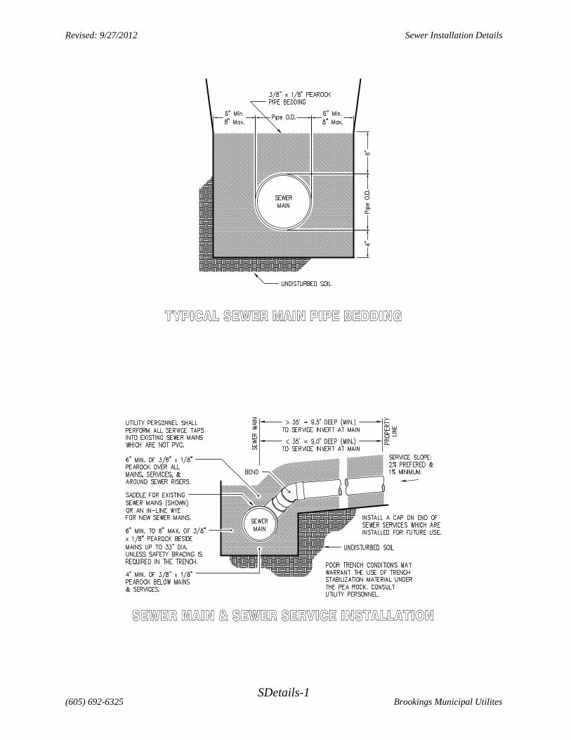
(605) 692-6325 Brookings Municipal UtilitesSDetails-1
Revised: 9/27/2012 Sewer Installation Details

(605) 692-6325 Brookings Municipal UtilitesSDetails-2
Revised: 9/27/2012 Sewer Installation Details
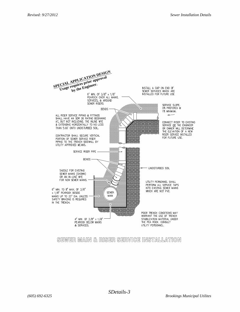
SPECIAL APPLICATION DESIGN
Usage requires prior approval
by the Engineer.
(605) 692-6325 Brookings Municipal UtilitesSDetails-3
Revised: 9/27/2012 Sewer Installation Details

SPEC
IAL
APP
LIC
ATI
ON
DES
IGN
Usa
ge r
equi
res p
rior
app
rova
l
by th
e En
gine
er.
(605) 692-6325 Brookings Municipal UtilitesSDetails-4
Revised: 9/27/2012 Sewer Installation Details

(605) 692-6325 Brookings Municipal UtilitesSDetails-5
Revised: 9/27/2012 Sewer Installation Details

(605) 692-6325 Brookings Municipal UtilitesSDetails-6
Revised: 9/27/2012 Sewer Installation Details

(605) 692-6325 Brookings Municipal UtilitesSDetails-7
Revised: 9/27/2012 Sewer Installation Details
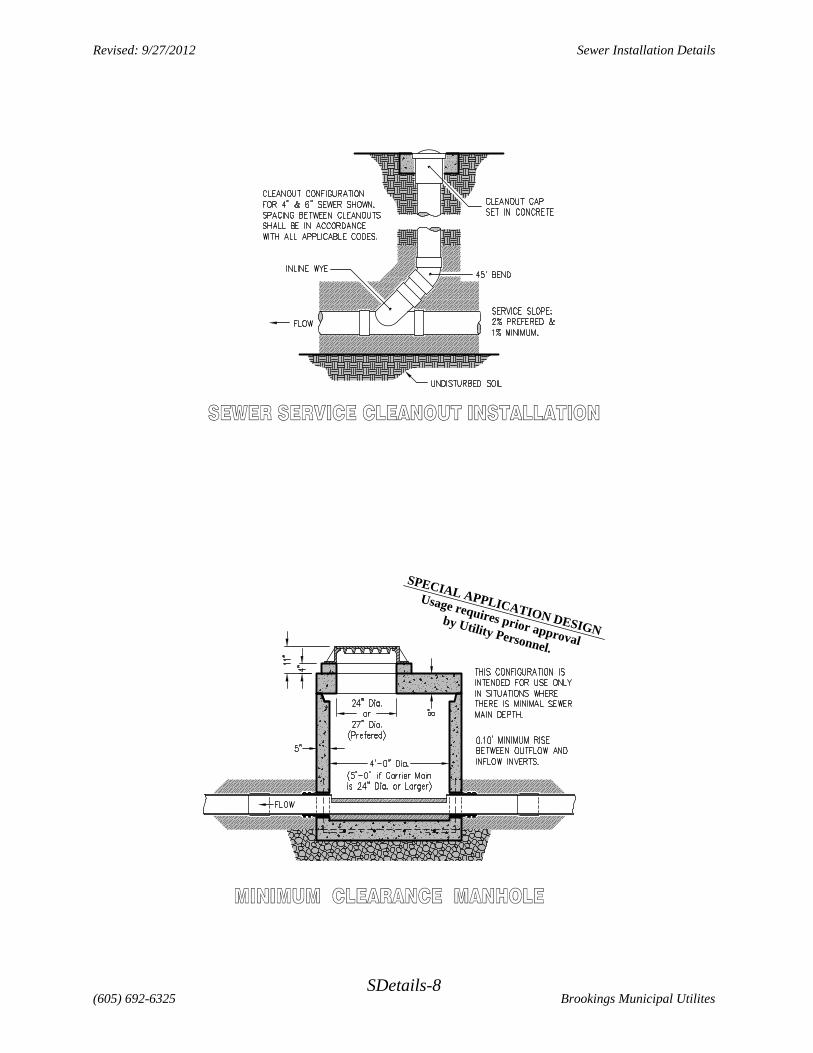
by Utility Personnel.
Usage requires prior approval
SPECIAL APPLICATION DESIGN
(605) 692-6325 Brookings Municipal UtilitesSDetails-8
Revised: 9/27/2012 Sewer Installation Details

(605) 692-6325 Brookings Municipal UtilitesSDetails-9
Revised: 9/27/2012 Sewer Installation Details

(605) 692-6325 Brookings Municipal UtilitesSDetails-10
Revised: 9/27/2012 Sewer Installation Details
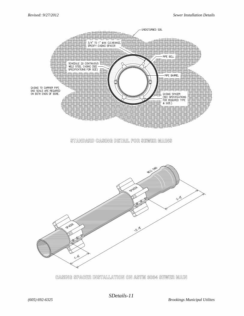
(605) 692-6325 Brookings Municipal UtilitesSDetails-11
Revised: 9/27/2012 Sewer Installation Details