sandvik ch430:01, :02 · the drawings show the points on the crusher and tank unit where...
TRANSCRIPT

IMA Appendix A Doc. no. S 223.651.en
SANDVIK CH430:01, :02

This document is valid for:
Serial no. / Machine no. Sign.
SANDVIK CH430:01, :02 © Copyright 2008 Sandvik SRP AB.All rights reserved. No parts of this document may be reproduced or copied in any form or by any means without written permission from Sandvik SRP AB. All data and information in this manual may be changed without further notice. Reservations for misprints.
Document number: S 223.651.enOriginal instructionsIssue: 20110511Version: 02
SandvikStationsplan, SE-233 81 Svedala, SwedenTel: +46 (0)40 409000, Fax: +46 (0)40 409260www.sandvik.com

Appendix A:Installation drawings
A-3IM Sandvik CH430:01, :02

IM Sandvik CH430:01, :02
A.1 General The following drawings show machine dimensions, connection positions and dimensions, and access dimensions. All dimensions must be respected. Dimensions are given in millimeters with inch dimension in brackets.
A.1.1 Mechanical drawings
A.1.2 Electrical drawings
NOTE! The motor can be installed on either side of the crusher.
Drawing name Drawing No. NoteInstallation 442.7992
Oil tank installation 442.8326
Oil connection (standard) 442.9820
Oil connection (USA) 442.9819
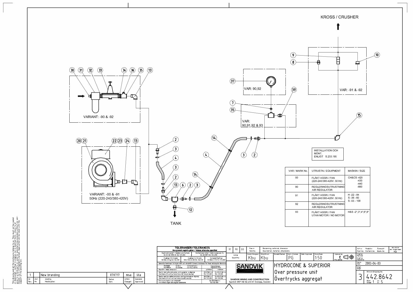
Air over-pressure (blower/compressed air) 442.8642
Foundation loads 442.9912
Drawing name Drawing No. NotePiping and instrument diagram, typical installation 194.0434
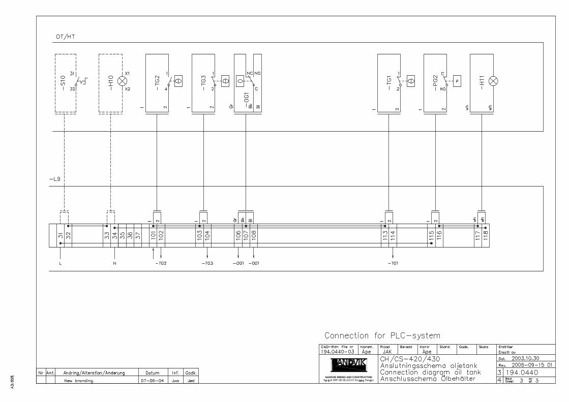
Connection diagram, oil tank 194.0440
Circuit diagram 194.0441
Instrument list 195.0620
Sensor list 195.0621
Modification of return oil flow switch 194.0190 option
Connection of extra heating elements 194.0191 option
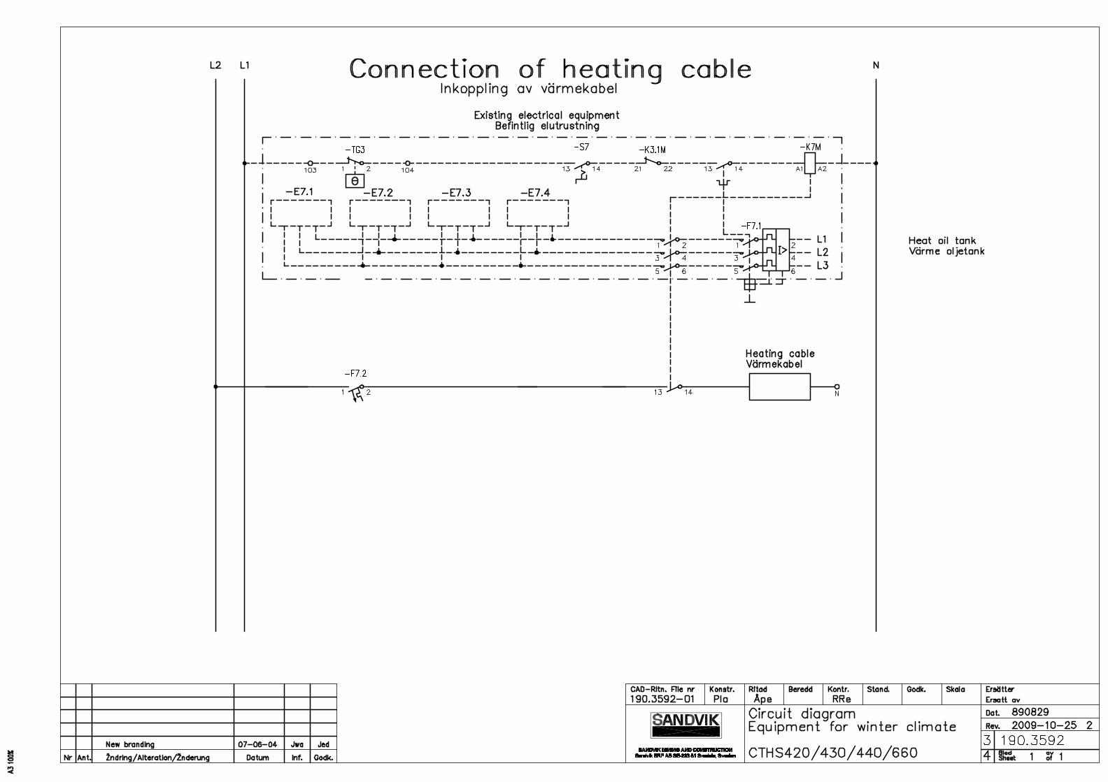
Connection of heating cable 190.3592 option
Connection of heater for Hydroset oil 190.3590 option
A-4 © 2008 Sandvik SRP ABS 223.651.en-01

IM Sandvik CH430:01, :02
A.1.3 Foundation loadsDrawing No. 442.9912
The values are applicable for the maximum eccentric throw (36 mm (1.42")).
Forces on foundation at each attachment point.
CH430:01, :02 fixed installation kN lbfVertical static load including material* 31 6970
Dynamic load during normal operation f = 6.0 Hz:
Rotating horizontal force (H) 10 2250
Cyclic vertical force (V) ±15 3375
* Material volume =1.20 m3 (40 ft3)* Bulk density = 1 800 kg/m3 (3 970 lbs)
CH430:01, :02 on rubber dampers kN lbfVertical static load including material* 31 6970
Dynamic load during starting and stopping:
Rotating horizontal force (H) 3 675
Cyclic vertical force (V) ±12 2700
Dynamic load during normal operation f = 6.0Hz
Rotating horizontal force (H) 1 225
Cyclic vertical force (V) ±3 675
* Material volume = 1.20 m3 (40 ft3)* Bulk density = 1 800 kg/m3 (3 970 lbs)
Horizontal displacement:± 15 mm in all directions during starting and stopping± 5 mm in all directions during operation
CH430:01, :02 with subframe on rubber dampers kN lbfVertical static load including material* 41 9220
Dynamic load during starting and stopping:
Rotating horizontal force (H) 3 675
Cyclic vertical force (V) ±12 2700
Dynamic load during normal operation f = 6.0 Hz
Rotating horizontal force (H) 1 225
Cyclic vertical force (V) ±3 675
* Material volume = 1.20 m3 (40 ft3)* Bulk density = 1 800 kg/m3 (3 970 lbs)
Horizontal displacement:± 15 mm in all directions during starting and stopping± 5 mm in all directions during operation
A-5© 2008 Sandvik SRP AB S 223.651.en-01

IM Sandvik CH430:01, :02
A.1.4 Mechanical connectionsDrawing No. 442.9820 (standard) Drawing No. 442.9819 (USA)The drawings show the points on the crusher and tank unit where connections are made, and also show the hoses that are supplied.
This overview shows general information about the connections for the cone crusher and its accessories.
Tank unit Dimension Max pressure A Lubrication oil from crusher Rp 2" internal thread
B Lubrication oil to crusher Rp 1½" internal thread
C Hydroset Rp ¾" internal thread
D To oil heat exchanger Rp 1"
E From oil heat exchanger Rp 1"
F, G Over-pressure air Rp ¾" internal thread
Crusher H Over-pressure air Rp ¾" internal thread
I Lubrication oil to tank R 2"
K Lubrication oil from tank G 1½" B
L Hydroset G ¾" B
Water/oil heat exchanger (option)M Oil inlet G 1½" B
N Water outlet G 1½" B
O Water inlet Rp 1½" B
P Oil outlet G 1½" B
Air/oil heat exchanger Q Oil outlet G 1¼"
R Oil inlet G 1¼"
A-6 © 2008 Sandvik SRP ABS 223.651.en-01

IM Sandvik CH430:01, :02
Mechanical connections overview
GH
IK
L
A
F
B
C
M N
O P
R
Q
E
D
A-7© 2008 Sandvik SRP AB S 223.651.en-01

IM Sandvik CH430:01, :02
A.1.5 Cable overviewThis cable overview shows general information about electrical cables not included in the delivery from Sandvik. Site specific signal cables are excluded from this table.
NOTE! All cable types and dimensions must meet local legislation.
Cable designation
Object Cable path Rating Notes
From To 50 Hz 60 Hz
W1-M1 Crusher main motor Switchgear -M1 75–132 kW
W1-M2 Lubrication oil pump Switchgear -L9 1.5 kW 1.7 kW
W1-M3 Cooling fan Switchgear -M3 1.5 kW 1.7 kW Option
W1-M8 Over-pressure fan Switchgear -M8 0.37 kW 0.43 kW Option
W1-E7 Oil tank heating Switchgear -L9 2.5–8.2 kWdepending on voltage and number of heaters
W1-CV Power supply Switchgear -L9 - -
W2-CV Signals from switches -L9 Control system or similar
- -
A-8 © 2008 Sandvik SRP ABS 223.651.en-01


INSTRUMENT LISTPlant:Equipment Tag No:Equipment Name: HYDROCONE CH/CS-420/430Equipment Supplier: SANDVIK ROCK PROCESSING
IDENTIFICATION INSTRUMENT TYPE APPLICATION INSTRUMENT DETAILS REMARKSPlant SRP Model Range Part No. Manufacturer
Tag No. Tag No.-TI1 Thermometer Return oil temperature (main) ICF 60 0-120ºC 923.0192-00 LTR Lubr. system
-PI1 Pressure gauge Hydroset pressure 100M20-2 0-6 MPa 923.0379-00 Tempress Hydroset system
-PI2 Pressure gauge Oil pressure (main) 2748 D63 0-1.6 MPa 923.0193-00 Wika Lubr. system
-LI1 Oil level indicator Oil level in tank (main) H00361-010 High/Low 914.0174-00 Parker Hannifin Lubr. system
-LI2 Oil level indicator Oil level in tank (Hydroset) H00361-007 High/Low 914.0170-00 Parker Hannifin Hydroset system
Sandvik Rock ProcessingRev: 01/New brandingDate: 07-06-15/Jwa
195.0620 Instrument list CH_CS-420_430 Typical installation1 (1) .

SENSOR LISTPlant:Equipment Tag No:Equipment Name:Equipment Supplier:
SENSOR TYPE APPLICATION REMARKSPlant SRP Model Range Part No. Output Contact Manufacturer
Tag No. Tag No. rating-TG1 Thermostat Return oil temperature RT101 17-5003 923.0095-00 NC/NO 4A,400V Danfoss Lubr. system-TG2 Thermostat Oil cooling RT101 17-5003 923.0095-00 NC/NO 4A,400V Danfoss - “ - “ --TG3 Thermostat Oil heating RT101 17-5003 923.0095-00 NC/NO 4A,400V Danfoss - “ - “ --OG1 Flow indicator Return oil flow HeliFloat PF 984.1008-00 NC/NO 6A,240V HeliSim - “ - “ --PG2 Pressure guard Filter diff. pressure (main) PIS3097 2.2 bar 912.0127-00 NO 2,5A 230V Knecht - “ - “ -
-B1N Position sensor Mainshaft position (HS-2800) EDS 160 0-160mm 984.0390-00 4-20mA Micro Epsilon ASRi-B1N Position sensor Mainshaft position (HS-3800) EDS 250 0-250mm 984.0391-00 4-20mA Micro Epsilon ASRi-B2N Press. transmitter Hydroset pressure 3376 0-250bar 923.0507-00 4-20mA Tecsis ASRi-B3N Temp. transmitter Return oil temperature FLEXTOP PT-100 0-200°C 923.0489-00 4-20mA Bourdone Sed. ASRi-U1N Power transducer Drive motor power draw P200-054 4-20mA Tillquist ASRi
SENSOR DETAILS
HYDROCONE CH/CS-420/430SANDVIK ROCK PROCESSING
IDENTIFICATION
Sandvik Rock ProcessingRev: 01/ New brandingDate: 07-06-05/Jwa
195.0621 Sensor list CH_CS-420_430 Typical installation1 (1)