san diego gas & electric company … plrp_gate...may 02, 2017 · san diego gas & electric...
TRANSCRIPT

SAN DIEGO GAS & ELECTRIC COMPANY CLEVELAND NATIONAL FOREST
POWER LINE REPLACEMENT PROJECTS GATE PLAN
MAY 2017
PREPARED FOR:

Gate Plan
San Diego Gas & Electric Company May 2017 Cleveland National Forest Power Line Replacement Projects i
TABLE OF CONTENTS
1 – INTRODUCTION................................................................................................................... 1 2 – OBJECTIVES ......................................................................................................................... 1 3 – MITIGATION MEASURES ................................................................................................. 1 4 – PLAN IMPLEMENTATION ................................................................................................ 2
4.0 Review Criteria ..........................................................................................................2 4.1 Schedule .....................................................................................................................2 4.2 Maintenance ...............................................................................................................2
LIST OF ATTACHMENTS
Attachment A: USFS Gate Specifications and Guidelines Attachment B: Gate Plan Schedule
LIST OF APPENDICES
Appendix A: TL 629E Gate Map Book Appendix B: TL 625B Gate Map Book Appendix C: TL 682 Gate Map Book Appendix D: TL 6931 Gate Map Book Appendix E: TL 626 Gate Map Book Appendix F: TL 625D Gate Map Book Appendix G: TL 629A Gate Map Book Appendix H: TL 629C Gate Map Book Appendix I: TL 629D Gate Map Book Appendix J: TL 6923 Gate Map Book Appendix K: TL 625C Gate Map Book


Gate Plan
San Diego Gas & Electric Company May 2017 Cleveland National Forest Power Line Replacement Projects 1
1 – INTRODUCTION
This Gate Plan (Plan) describes San Diego Gas & Electric Company’s (SDG&E’s) actions to deter unauthorized vehicular access to specifically designated or restricted areas via SDG&E access roads authorized by the Master Special Use Permit (MSUP). The Project includes a variety of activities in support of the following construction components:
• replacement of approximately 1,400 existing wood poles with fire-resistant, weathered steel poles;
• undergrounding of approximately 26 miles of existing 12 kilovolt (kV) distribution lines; • removal of approximately 30 miles of existing 12 kV and 19 miles of existing 69 kV
overhead facilities; and • closure of approximately 24 miles of access roads.
This Plan was prepared in accordance with Mitigation Measure (MM) REC-1, as described in the Project’s Final Environmental Impact Report/Environmental Impact Statement’s (FEIR/EIS) Mitigation Monitoring, Compliance, and Reporting Program and the United States Forest Service (USFS) Record of Decision.
2 – OBJECTIVES
The management practices and activities in this Plan are intended to accomplish the following objectives:
• Provide a framework for the review process necessary to determine the locations of gates and/or other barriers needed along SDG&E exclusive-use access roads and on land managed by the USFS.
• Provide gate designs that meet the USFS engineering standards. • Identify the locations and schedule for the installation of gates and/or other barriers.
3 – MITIGATION MEASURES
The full text of MM REC-1 is provided as follows:
MM REC-1: Installation of Gates and Appropriate Signage: To deter unauthorized access to specially designated or restricted areas via SDG&E access roads authorized by the MSUP, the project applicant shall submit a plan and schedule for gate (or other barriers, such as pipe rails, where appropriate) installation to the Forest Service for approval. Gates will meet Forest Service engineering standards, and designs will be approved by the Forest Service prior to installation. In addition, appropriate deterrence signage approved by the Forest Service shall be installed on gates to SDG&E access roads. Maintenance of gates and signage shall be the responsibility of the project applicant.
Gate Plan
May 2017 San Diego Gas & Electric Company 2 Cleveland National Forest Power Line Replacement Projects
4 – PLAN IMPLEMENTATION
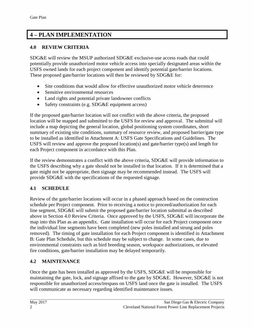
4.0 REVIEW CRITERIA
SDG&E will review the MSUP authorized SDG&E exclusive-use access roads that could potentially provide unauthorized motor vehicle access into specially designated areas within the USFS owned lands for each project component and identify potential gate/barrier locations. These proposed gate/barrier locations will then be reviewed by SDG&E for:
• Site conditions that would allow for effective unauthorized motor vehicle deterrence • Sensitive environmental resources • Land rights and potential private landowner conflicts • Safety constraints (e.g. SDG&E equipment access)
If the proposed gate/barrier location will not conflict with the above criteria, the proposed location will be mapped and submitted to the USFS for review and approval. The submittal will include a map depicting the general location, global positioning system coordinates, short summary of existing site conditions, summary of resource review, and proposed barrier/gate type to be installed as identified in Attachment A: USFS Gate Specifications and Guidelines. The USFS will review and approve the proposed location(s) and gate/barrier type(s) and length for each Project component in accordance with this Plan.
If the review demonstrates a conflict with the above criteria, SDG&E will provide information to the USFS describing why a gate should not be installed in that location. If it is determined that a gate might not be appropriate, then signage may be recommended instead. The USFS will provide SDG&E with the specifications of the requested signage.
4.1 SCHEDULE
Review of the gate/barrier locations will occur in a phased approach based on the construction schedule per Project component. Prior to receiving a notice to proceed/authorization for each line segment, SDG&E will submit the proposed gate/barrier location submittal as described above in Section 4.0 Review Criteria. Once approved by the USFS, SDG&E will incorporate the map into this Plan as an appendix. Gate installation will occur for each Project component once the individual line segments have been completed (new poles installed and strung and poles removed). The timing of gate installation for each Project component is identified in Attachment B: Gate Plan Schedule, but this schedule may be subject to change. In some cases, due to environmental constraints such as bird breeding season, workspace authorizations, or elevated fire conditions, gate/barrier installation may be delayed temporarily.
4.2 MAINTENANCE
Once the gate has been installed as approved by the USFS, SDG&E will be responsible for maintaining the gate, lock, and signage affixed to the gate by SDG&E. However, SDG&E is not responsible for unauthorized access/trespass on USFS land once the gate is installed. The USFS will communicate as necessary regarding identified maintenance issues.

ATTACHMENT A: USFS GATE SPECIFICATIONS AND GUIDELINES


MONSTER GATE SPECIFICATIONS AND GUIDELINES


MONSTER GATE
CONCRETE REINFORCEMENT Section 03 20 00-1
SECTION 03 20 00 - CONCRETE REINFORCEMENT
PART 1 - GENERAL
1.1 SECTION INCLUDES
A. Reinforcing steel bars, wire fabric and accessories for cast-in-place concrete.
1.2 RELATED SECTIONS
A. Section 03 10 00 - Concrete Formwork.
B. Section 03 30 00 - Cast-in-Place Concrete.
1.3 REFERENCES
A. ACI 30 - Structural Concrete for Buildings.
B. ACI 318 - Building Code Requirements For Reinforced Concrete.
C. ACI SP-66 - American Concrete Institute – Detailing Manual.
D. ASTM A82 - Cold Drawn Steel Wire for Concrete Reinforcement.
E. ASTM A185 - Welded Steel Wire Fabric for Concrete Reinforcement.
F. ASTM A615 - Deformed and Plain Billet Steel Bars for Concrete Reinforcement.
G. AWS D 1.4 - Structural Welding Code for Reinforcing Steel.
H. CRSI - Concrete Reinforcing Steel Institute – Manual of Practice.
I. CRSI 63 – Recommended Practice For Placing Reinforcing Bars.
J. CRSI 65 – Recommended Practice For Placing Bar Supports, Specifications and
Nomenclature.
1.4 SUBMITTALS FOR REVIEW
A. Section 01300 – Submittals: Procedures for submittals.
B. Shop Drawings: Indicate bar sizes, spacing, locations, and quantities of reinforcing steel,
Bending and cutting schedules, and supporting.
1.5 SUBMITTALS FOR INFORMATION
A. Section 01300 – Submittals: Procedures for submittals.

MONSTER GATE
CONCRETE REINFORCEMENT Section 03 20 00-2
B. Manufacturer’s Certificate: Certify that products meet or exceed specified requirements.
C. Submit certified copies of mill report or reinforcement materials analysis.
1.6 QUALITY ASSURANCE
A. Perform Work in accordance with ACI 301 and ACI SP-66.
1.7 MEASUREMENT AND PAYMENT
A. No separate measurement or payment will be made for work specified in this section.
PART 2 - PRODUCTS
2.1 REINFORCEMENT
A. Reinforcing Steel: ASTM A615, 60 ksi yield grade; deformed billet steel bars.
2.2 ACCESSORIES
A. Tie Wire Minimum 16.
B. Chairs, Bolsters, Bar Supports, Spacers: Sized and shaped for strength and support of
reinforcement during concrete placement conditions including load bearing pad on
bottom to prevent vapor barrier puncture.
C. Special Chairs, Bolsters, Bar Supports, Spacers Adjacent to Weather Exposed Concrete
Surfaces: Stainless steel type; size and shape as required.
2.3 FABRICATION
A. Fabricate concrete reinforcing in accordance with ACI SP-66.
B. Locate reinforcing splices not indicated on drawings, at point of minimum stress. Review
location of splices with Contracting Officer.
PART 3 - EXECUTION
3.1 PLACEMENT
A. Place, support and secure reinforcement against displacement. Do not deviate from
required position.
B. Do not displace or damage vapor barrier.
C. Accommodate placement of formed openings.

MONSTER GATE
CONCRETE REINFORCEMENT Section 03 20 00-3
D. Maintain concrete cover around reinforcing as follows:
Item: Coverage:
Footings and Concrete Formed Against Earth 3 inch
Slabs on Grade 3 inch
3.2 FIELD QUALITY CONTROL
A. Section 01400 - Quality Control: Field inspection.
B. Inspect for acceptability.
END OF SECTION 03200

MONSTER GATE
CAST-IN-PLACE CONCRETE Section 03 30 00-1
SECTION 03 30 00 – CAST–IN-PLACE CONCRETE
PART 1 - GENERAL
1.1 SECTION INCLUDES
A. This section includes reinforced concrete and replacement of reinforced concrete. The work includes
preparation of surfaces, mixing, placement, and finishing of concrete.
1.2 RELATED SECTIONS
A. 03 30 00 CONCRETE REINFORCMENT.
1.3 REFERENCES
A. ACI 211.1 - Selecting Proportions for Normal, Heavyweight, and Mass Concrete.
B. ACI 301 - Structural Concrete for Buildings.
C. ACI 302 - Guide for Concrete Floor and Slab Construction.
D. ACI 304 - Recommended Practice for Measuring, Mixing, Transporting and Placing Concrete.
E. ACI 305R - Hot Weather Concreting.
F. ACI 306R - Cold Weather Concreting.
G. ACI 308 - Standard Practice for Curing Concrete.
H. ACI 318 - Building Code Requirements for Reinforced Concrete.
I. ASTM C33 - Concrete Aggregates.
J. ASTM C94 - Ready-Mixed Concrete.
K. ASTM C150 - Portland Cement.
L. ASTM C260 - Air Entraining Admixtures for Concrete.
M. ASTM C494 - Chemical Admixtures for Concrete.
N. ASTM D994 - Preformed Expansion Joint Filler for Concrete (Bituminous Type).
O. ASTM D1190 - Concrete Joint Sealer, Hot-Poured Elastic Type.
P. ASTM C231 – Air Content of Freshly Mixed Concrete by the Pressure Method.
Q. ASTM C1116 – Standard Specification for Fiber Reinforced Concrete and Shotcrete.

MONSTER GATE
CAST-IN-PLACE CONCRETE Section 03 30 00-2
1.4 MEASUREMENT AND PAYMENT
A. Measurement and payment for work performed under this Section will be made under those pay items
as listed in the Schedule of Items and will constitute full compensation for all materials, labor,
equipment, testing, and incidentals necessary to complete the work as specified herein and AS
SHOWN ON THE DRAWINGS.
PART 2 – PRODUCTS
A. Portland Cement shall conform to ASTM C 150, Type IIA cement. The Contractor shall obtain from
his supplier of cement or concrete a certificate stating that the cement complies with this
specification.
B. Aggregates shall conform to ASTM C 33. Maximum size of aggregate shall be either one (1) inch or
not larger than three-quarters (3/4) of the minimum clear spacing between reinforcing bars or between
reinforcing concrete surface with the smaller size governing.
C. Water (Used in Mix) shall be clean and free from injurious amounts of acids, alkalis, salts, organic
matter or other deleterious substances.
D. The water/cement ratio of the design mix shall be maintained at all times regardless of making field
adjustment due to weather or placement conditions. Maximum allowable mixing water shall not
exceed seven (7) gallons per sack. Mixing water shall be reduced by the amount of moisture in the
aggregate above saturated surface dry conditions.
E. The slump of the concrete as designed and placed on the job shall be four inches maximum when
tested in accordance with ASTM C143.
F. Concrete shall be air-entrained, and shall contain 5 percent plus or minus 1 percent entrained air as
determined by test procedure ASTM C138. Only air-entrained agents meeting the requirements of
ASTM C260 will be permitted and shall be added at the mixer.
G. Provide concrete to the following criteria: (This data and all admixtures used shall be shown on all
tickets for all material delivered to the job site.
FOOTINGS
Unit Measurement
Compressive Strength (28 day) 3000 psi
Water/Cement Ratio (maximum) 0.45
Aggregate Size (maximum) 1 inch
H. Admixture: A type that increases the workability and reduces the water demand of the concrete, the
brand and amount used subject to the approval of the Contracting Officer and shown in respective
mix designs. No admixture containing calcium chloride or salt shall be used.

MONSTER GATE
CAST-IN-PLACE CONCRETE Section 03 30 00-3
1. Air Entrainment: ASTM C260, 5% plus or minus 1%
2. Chemical: ASTM C494
I. Limits: The allowable mix design tolerances shall not exceed one percent for cement and water, two
percent for each aggregate, or one percent for aggregates weighed cumulatively.
A. Moisture-Retaining Cover: One of the following, complying with ASTM C171:
1. Waterproof paper.
2. Polyethylene film.
3. Polyethylene-coated burlap.
B. Liquid Membrane-Forming Curing Compound: ASTM C309. Use type 1 or 1-D clear cure
compound.
C. For cold weather protection use curing blankets with a minimum 3.37 R value.
2.1 CONCRETE MIXING
A. Depending on local conditions, or with approval of the Contracting Officer, the methods of mixing
may be limited to one of the following:
1. Batching at a Central Plant or “Ready Mixed Concrete” shall comply with requirements of ASTM
C94, and as specified herein.
2. Job Site Mixing: Mix materials for concrete in appropriate drum type batch mechanical machine
mixer. For mixers of one cubic yard or smaller capacity, continue mixing at least 1-1/2 minutes,
but not more than 5 minutes after ingredients are in mixer, before any part of batch is released.
PART 3 - EXECUTION
3.1 EXAMINATION
A. Verify that anchors, plates, reinforcement and other items to be cast into concrete are accurately
placed, positioned securely, and will not cause hardship in placing concrete.
3.2 MIXING AND HAULING
A. Batching and Mixing at a Central Plant Conforming to ASTM C94: The method herein contemplated
is ordinarily referred to as “Ready-Mixed Concrete”, and may only be employed if the time interval
between mixing at the plant and discharge into the forms does not exceed 90 minutes. This time
limitation may be still further reduced when high ambient air temperature or the high temperature of
the batch ingredients indicate a shorter time period is required. The mixture shall be agitated
continuously from the time the truck is loaded until time of discharge.

MONSTER GATE
CAST-IN-PLACE CONCRETE Section 03 30 00-4
B. Batching and Mixing at Site of Work: Concrete shall be mixed thoroughly in a batch mixer of
approved type and capacity for a period of not less than 1-1/2 minutes after all component materials,
including water, are in a drum, or as specified by the manufacturer of the mixer.
3.3 INSTALLATION OF EMBEDDED ITEMS
A. Secure or insert sleeves, bollards, posts, bolts, anchors, inserts, or other hardware in forms and be
responsible for any and all changes in the position of such items after they have been set in forms.
3.4 CONCRETE PLACEMENT
A. Environmental Conditions:
1. Cold Weather Placing: When air temperature has fallen to or is expected to fall below 40 deg F,
protect concrete work from physical damage or reduced strength which could be caused by frost,
freezing actions, or low temperatures, in compliance with ACI 306R. Do not place concrete on
frozen subgrade or subgrade containing frozen materials. Submit cold weather protection product
data before concrete is ordered.
2. Hot Weather Placing: When air temperature is above or expected to be above 85 deg For weather
conditions exist that would seriously impair quality and strength of concrete, place concrete in
compliance with ACI 305R.
B. Preplacement Inspection: Before placing concrete, the Contracting Officer shall inspect and approve
the complete installation for formwork, reinforcement, and items to be embedded or cast-in. Moisten
wood forms immediately before placing concrete where form coatings are not used.
C. Placing Concrete:
1. Concrete shall be placed in such a manner as to avoid segregation but, in no case shall the
concrete be dropped freely more than five feet. Deposit concrete as nearly as practicable to its
final location to avoid segregation.
2. Concrete shall be placed continuously. If a section cannot be placed continuously, provide
construction joints as herein specified. Deposit concrete in a manner to avoid inclined
construction joints or the formation of seams or planes of weakness. When placement consists of
several layers, place each layer while preceding layer is plastic to avoid cold joints.
3. Protect adjacent finish materials against spatter during concrete placement.
4. Consolidate placed concrete by mechanical vibrating equipment supplemented by hand-spading,
rodding or tamping to provide a smooth void free surface against formwork.
5. Do not use vibrators to transport concrete inside forms or cause segregation of mix.
6. Ensure reinforcement, inserts, embedded parts, formed expansion and contraction joints are not
disturbed during concrete placement.

MONSTER GATE
CAST-IN-PLACE CONCRETE Section 03 30 00-5
7. Maintain records of concrete placement. Record date, location, quantity, air temperature, and test
samples taken.
3.5 CONCRETE CURING AND PROTECTION
A. Immediately after placement, protect concrete from premature drying, excessively hot or cold
temperatures, and mechanical injury. Concrete shall be cured for a minimum of 7 days by one of the
following methods:
1. Provide moisture curing by keeping surface continuously wet by covering with water or water-
fog spray, or absorptive cover.
2. Moisture-Retaining Cover: Place cover in widest practicable width with sides and ends lapped at
least 3 inches and sealed by waterproof tape or adhesive. Immediately repair any holes or tears
during curing period using cover material and waterproof tape.
3. Provide curing and sealing compound in accordance with manufacturer’s recommendations.
Recoat areas subjected to heavy rainfall within 3 hours after initial application. Maintain
continuity of coating and repair damage during curing period.
4. Do not use plastic sheets or any curing products which discolor.
3.6 CONCRETE SURFACE REPAIRS
A. Surface repairs shall be made with cement mortar immediately after removal of forms, acceptable to
the Contracting Officer. Repairs include filling in holes or openings left for other trades, after work
of other trades is in place. Repairs include honeycombs, rock pockets, and void over ¼ inch in any
dimension, holes left by ties, rods, and bolts, cracks in excess of 0.01 inch in concrete surfaces.
B. Remove defective areas to sound concrete with clean square cuts. Thoroughly clean, dampen with
water, and brush-coat the area to be patched with an approved bonding agent. Place patching mortar
after bonding compound has dried. Compact mortar and keep continuously moist for not less than 72
hours. Alternate repair methods are subject to approval by the Contracting Officer. If defects cannot
be repaired to satisfaction of Contracting Officer, concrete shall be removed and replaced.
C. Correct high areas in slabs after cure period by grinding.
END OF SECTION 03 30 00

MONSTER GATE
SITE IMPROVEMENTS Section 32 30 00 - 1
SECTION 32 30 00 – SITE IMPROVEMENTS
PART 1 – GENERAL
1.1 SCOPE: This Section includes the following:
A. Fabrication and installation of steel pipe gates and all appurtenances.
1.2 MEASUREMENT AND PAYMENT: Measurement for work performed under this section will be made
under those pay items as listed in the Schedule of Items and will constitute full compensation for all
materials, labor, equipment, testing and incidentals necessary to complete the work and provide a complete
and operational gate for the site as specified herein and AS SHOWN ON THE DRAWINGS. Concrete
footings and all signage is considered incidental to line item 32 30 00.
PART 2 – PRODUCTS
2.1 The gate and all components are to be constructed of Schedule 40 and Schedule 80 steel pipe AS SHOWN
ON THE DRAWINGS. After the gate is constructed, all welds completed and all exposed cuts shall be
ground smooth, gate is to be powder coated white. Final gate posts locations shall be determined by the COR.
2.2 Signs and reflectors shall be installed on both sides of the gates and in locations AS SHOWN ON THE
DRAWINGS.
PART 3 – EXECUTION
3.1 Steel Pipe Gate
a. Install gate AS SHOWN ON THE DRAWINGS.
b. Concrete shall be minimum 3000 psi in accordance with Specification 03 30 00, Cast-In-Place
Concrete.
c. Allow concrete to set a minimum of 7 days before hanging the gate on the gate post.
d. Remove all construction debris generated by the gate install prior to final approval.
END OF SECTION 32 20 00


3 EACH HORIZONTAL GATE MEMBERSARE 2.5" DIAMETER SCHEDULE 40 STEELPIPE (ASTM A36) BY 14'-0" LONG, TYP.,WELDED TO VERTICAL MEMBERS ANDGATE HINGE PIPE.
GATE HINGE PIPE IS 8" DIAMETER SCHEDULE40 STEEL PIPE (ASTM A36). PROVIDE 8"DIAMETER BY 3/8" THICK STEEL STOCK TOPCAP WELDED TO POST WITH FULLPENETRATION WELDS, GROUND FLUSH.
6 EACH VERTICAL MEMBERS ARE 2.5"DIAMETER SCHEDULE 40 STEEL PIPE (ASTMA36), CRIMPED DOWN TO 1" AT BOTH ENDS,TYP., WELDED TO HORIZONTAL MEMBERSWITH 14" FILLETS WELDS ALL AROUND.EQUALLY SPACED VERTICAL MEMBERS.
LOCKING PLATE, 3 INCH x 5 1/4 INCH x 1INCH THICK STOCK STEEL WELDED TOGATE.
38" GUSSET PLATE, TYPICAL. SEE DETAIL C
45 DEGREE ANGLE CUT, 1/4" WELD ALLAROUND, TYP. GRIND FLUSH.
1/2 INCH THICK, 10 INCH DIAMETER COLLAR, WITH14" FILLETS WELD, ALL AROUND.
VERTICAL MEMBER IS 2.5" DIAMETERSCHEDULE 40 STEEL PIPE (ASTM A36) 3'-0"LONG, TYP., WELDED TO HORIZONTALMEMBERS.
3'3'-6"
NOTES:1. ALL JOINTS TO BE 14 INCH FILLET WELD ALL AROUND.
2. FINISH IS TO BE POWDER COATED, PER SPECIFICATION, COLOR WHITE. NO POWDER
COAT ON BOTTOM 2'-6" OF GATE HINGE POST, LOCK POST AND LOCK OPEN POST.
3. ALL EXPOSED CUTS ARE TO BE GROUND SMOOTH.
1/4" FILLET WELD ALL AROUND
LOCK TEE 1/2" STEEL PLATE
DOUBLE LOCK BAR 7/8" STEEL BAR
1.75"
0.5"3"1" DIAMETER HOLE
1.75"
0.5"
7/8" DIAMETER0.5" DIAMETER
1.5"
0.5"
WELD 516" STEEL CHAIN, 12" LENGTH,
(1 EACH) TO INSIDE OF LOCK POST,CENTERED; AND (1 EACH) TO INSIDEOF LOCK OPEN POST, CENTERED;AND OTHER END WELDED TO LOCKTEE (1 EACH CHAIN FOR EACHPOST).
1.0"
1.0"
12"
12"
12 INCH DIAMETERHOLE, CENTERED.
SHEET OF
DRAWING
PROJECT NUMBER
CHECKED BY
SCALE
DATE
CHECKED BY
DESIGNED BY
DRAWN BY
A/E
FOR
EST:
DR
AW
ING
PRO
JEC
TN
AM
E:
NA
ME:
FOREST
REGIONSOUTHWEST
PACIFIC
DATENO. REVISIONS
R5
SERVICE
U S D A
MO
NS
TER
GA
TE 1
4' -
9" M
AX
GA
TE F
AB
RIC
ATI
ON
DE
TAIL
S A
- C
AS SHOWN
28JUL2016
MM
TM/WH
CLE
VEL
AN
D N
ATI
ON
AL
FOR
EST
1 3
1" = 1'- 0"
LOCK TEE DETAILNOT TO SCALEB
38" GUSSET PLATE DETAIL
1' = 1'-0"C
GATE DETAILA

LOCK AND LOCK OPEN POST CAPIS 8" DIA x 3/16" STEEL PLATEWELDED INTO PLACE
8" DIAMETER ACCESS HOLE
SEE DETAIL "D"
FINISHED GRADE
#8 REBAR 18" LONG THROUGHLOCK POST WITH 5"PROTRUDING EACH SIDE
LOCK AND LOCK OPEN POST IS 8" ØSCHEDULE 40 STEEL PIPE (ASTM A36) BY MIN.7' LONG. PIPE LENGTH SHALL BE ADJUSTEDTO FIT GROUND CONDITIONS.
7'-0" MIN.
3'-0"
2'-0"3" MIN. CLEARANCE
3" MIN. CLEARANCE
3" MIN. CLEARANCE, TYP.
COMPACTED NATIVE SOIL
COMPACTED NATIVE SOIL
LOCK POST
LOCK POST
3" x 5 1/4" x 1"LOCKING PLATE
3" x 5 1/4" x 1" LOCKINGPLATE WITH 1 9/16" DIAMETERHOLE CUT FOR LOCK ASSEMBLY
VERTICAL MEMBER OFGATE, 2.5" SCH 40 STEEL
8" DIAMETER ACCESS HOLEFOR LOCK ACCESS
2.5" SCH 40 VERTICAL GATE MEMBER8" DIAMETER ACCESS HOLE
3/16" FLAT PLATE WELDED TO INSIDELOCK POST AND LOCK OPEN POST TOSTOP KEY DROP/LOSS
6"
1-9/16" HOLE, HOLE DIAMETER SHALLBE ALTERED TO ACCOMMODATE TWOPAD LOCKS.
3/8" LOCK POST CAP
CUT SLOT FOR LOCKING PLATE.
CUT SLOT FOR LOCKING PLATE
8" Ø GATE HINGE PIPE
6" Ø GATE POST
FLAT STOCK 5/8" THICK, 1" WIDE X 3" LONGSHIMS, BEND AND WELD TO CONTOUR OF GATEHINGE POST (8 REQUIRED), 4 EACH POST, TOPAND BOTTOM
WELD 4 EACH SHIMS ~ 1" BELOW TOP OF GATEHINGE POST. WELD 4 EACH SHIMS ~1" ABOVE1/2" X 10" O.D. STEEL COLLAR, ON GATE HINGEPOST.
1 EACH 1/2" x 10" STEEL COLLAR WELDED TOHINGE PIPE (BOTTOM)
8" SCHEDULE 40 GATE HINGE PIPE
6" SCHEDULE 80 GATE HINGE POST
1 EACH 1/2" x 10" STEEL COLLARWELDED TO GATE POST 42" FROMTOP OF GATE POST
3/8" x 12" GUSSET, TYPICAL. SEE DETAIL C.
3/8" HINGE PIPE CAP
1/2" Ø HOLE FOR POWDER COAT HANGER
PLAN VIEW
ELEVATION VIEW
GATE HINGE PIPE IS 8"SCHEDULE 40 STEEL PIPEBY 3' - 6" LONG
7'-3 1/2" MIN.
GATE HINGE PIPE CAP IS 8" Øx 3/8" STEEL PLATE WELDEDINTO PLACE
GATE HINGE POST
GATE HINGE PIPE
CUT HOLES FOR REBAR
SHIM, SEE DETAIL F
SHIM, SEE DETAIL F
GATE POST IS 6" SCHEDULE 80STEEL PIPE MIN. 7' - 0" LONG. PIPE LENGTH SHALL BE ADJUSTED TOFIT GROUND CONDITIONS.
3"-6"
3'-6 1/2"
18"
6"
12" x 10" O.D.STEEL COLLAR
12" x 10" O.D. STEEL COLLAR
SHEET OF
DRAWING
PROJECT NUMBER
CHECKED BY
SCALE
DATE
CHECKED BY
DESIGNED BY
DRAWN BY
A/E
FOR
EST:
DR
AW
ING
PRO
JEC
TN
AM
E:
NA
ME:
FOREST
REGIONSOUTHWEST
PACIFIC
DATENO. REVISIONS
R5
SERVICE
U S D A
MO
NS
TER
GA
TE 1
4' -
9" M
AX
GA
TE F
AB
RIC
ATI
ON
DE
TAIL
S D
- G
AS SHOWN
28JUL2016
MM
TM/WH
CLE
VEL
AN
D N
ATI
ON
AL
FOR
EST
2 3
LOCK POST DETAILNOT TO SCALED
GATE HINGE POST SHIM DETAILNOT TO SCALEF
GATE HINGE POST & HINGE PIPE DETAILSNOT TO SCALEG
LOCK POST DETAILNOT TO SCALEE

MUTCD OBJECT MARKER, OM2-2V, CENTERED, ONE ON EACH SIDE OF POST, TYP.
BARRICADE MARKER (B-M-R-R) THIS SIDE, (B-M-L-R) FAR SIDE
CL
FINISHED GRADE
8" I.D. LOCK POST
14'-9" MAX.
NOTES:1. TOP AND BOTTOM 12" OF GATE HINGE PIPE AND RIDING SURFACES TO BE LIBERALLY COATED WITH LITHIUMBASED MOLYBDENUM DISULFIDE TYPE GREASE.
2. BARRICADE AND OBJECT MARKERS TO BE INSTALLED IN ACCORDANCE WITH MUTCD USING APPROVEDPRODUCTS.
3. AS STAKED BY COR WITH CONSIDERATION FOR DIRECTION OF SWING AND SIDE OF ROAD PLACEMENT, THE LOCKPOST AND LOCK OPEN POST FINAL LOCATIONS SHALL BE MEASURED AND VERIFIED BY CONTRACTOR TO ENSUREPROPER ALIGNMENT OF LATCH. BOTH LOCK POST AND LOCK OPEN POST SHALL BE INSTALLED AS SHOWN ONDRAWING. FIELD CUTTING OF LATCH AND POWDER COAT WILL NOT BE ALLOWED.
4. ALL REBAR AND PIPE EMBEDDED IN CONCRETE SHALL HAVE A 3 INCH MINIMUM COVER.
5. CONCRETE SHALL BE MINIMUM 3000 PSI AND SHALL BE INSTALLED IN ACCORDANCE WITH SPECIFICATIONSECTION 03 30 00, CAST IN PLACE CONCRETE.
6. CONCRETE SUPPORTS SHALL BE USED TO SET ALL POSTS BEFORE CONCRETE PLACEMENT, TO PROVIDE 3 INCHMINIMUM COVER.
7. CONTRACTOR SHALL ALLOW CONCRETE TO SET A MINIMUM OF 7 DAYS BEFORE HANGING GATE ON GATE POST.
8. CONTRACTOR SHALL PROVIDE AND INSTALL SIGNS USING ANTI-VANDAL HARDWARE.
2'-0" 3'-6" 3'-6" 2'-0"
S WI
NG
OFG
AT
E
2'-6"
14'-9" MAX.
GATE POST
EXCAVATE 3'-0" DIAMETER x 3'-3" DEEP
INSTALL 18 INCH LONG #8 REBAR THROUGH HOLE CUT IN POST,PROTRUDING EQUALLY EACH SIDE OF POST, TYP., TIE IN PLACE WITH WIRE.
8" I.D. GATE HINGE PIPE OVER 6" I.D. GATE POST
LOCK OPEN POST
LOCK POST
20"
40" LONG #4 REBAR, TYP.
18" TYP.
3'-0"
1'-0"
0'-10"
40" LONG #4 REBAR,TYP., 20" EACH SIDE
EXCAVATE 2'-0" DIAMETER x 3'-3" DEEP
EXCAVATE 2'-0" DIAMETER x 3'-3" DEEP
1'-0" PAST SWING OF GATE
1'-0" PAST SWING OF GATE
10" DIAMETER COLLAR RIDING SURFACES
HINGE PIPE CAP (3/8" THICK) AND GATE POST RIDING SURFACE
INSTALL 18 INCH LONG #8 REBAR THROUGH HOLE CUT IN POST, PROTRUDINGEQUALLY EACH SIDE OF POST, TYP., TIE IN PLACE WITH WIRE.
2'-0"3" MINIMUM CLEARANCE
R11-2 SIGN
18" x 18" x 38" THICK PLATE WELDED WITH 3
8" FILLETWELD ALL AROUND.
18" x 18" x 38" THICK PLATE WELDED WITH 3
8" FILLETWELD ALL AROUND.
12" DIAMETER HOLE
3' TYP.
3" MINIMUM CLEARANCE
6" MIN.
1" CLEARANCE
SHEET OF
DRAWING
PROJECT NUMBER
CHECKED BY
SCALE
DATE
CHECKED BY
DESIGNED BY
DRAWN BY
A/E
FOR
EST:
DR
AW
ING
PRO
JEC
TN
AM
E:
NA
ME:
FOREST
REGIONSOUTHWEST
PACIFIC
DATENO. REVISIONS
R5
SERVICE
U S D A
MO
NS
TER
GA
TE 1
4'-9
" MA
X
GA
TE IN
STA
LL D
ETA
ILS
H
NOT TO SCALE
14JULY2016
MM
TM
CLE
VEL
AN
D N
ATI
ON
AL
FOR
EST
3 3


LIGHTWEIGHT GATE SPECIFICATIONS


NOTES:TOP AND BOTTOM 12" OF GATE HINGE PIPE AND RIDING SURFACES TO BE LIBERALLYCOATED WITH LITHIUM BASED MOLYBDENUM DISULFIDE TYPE GREASE.
BARRICADE AND OBJECT MARKERS TO BE INSTALLED IN ACCORDANCE WITH MUTCD USINGPRODUCTS, AS APPROVED BY THE CO.
IT IS THE RESPONSIBILITY OF THE CONTRACTOR TO INVESTIGATE EXISTING SITECONDITIONS TO ENSURE EACH POST MEETS THE MINIMUM 3 FEET OF EMBEDMENT INCONCRETE.
FINAL LOCATION AS APPROVED BY CO WITH CONSIDERATION FOR DIRECTION OF SWINGAND SIDE OF ROAD PLACEMENT, THE LOCK POST AND LOCK OPEN POST FINAL LOCATIONSSHALL BE MEASURED AND VERIFIED BY CONTRACTOR TO ENSURE PROPER ALIGNMENT OFLATCH. BOTH LOCK POST AND LOCK OPEN POST SHALL BE INSTALLED AS SHOWN ONDRAWING. FIELD CUTTING OF LATCH AND POWDER COAT WILL NOT BE ALLOWED.
ALL REBAR AND PIPE EMBEDDED IN CONCRETE SHALL HAVE A 3 INCH MINIMUM COVER.
CONCRETE SHALL BE MINIMUM 3000 PSI AND SHALL BE INSTALLED IN ACCORDANCE WITHSECTION 03 30 00, CAST-IN-PLACE CONCRETE SPECIFICATION.
CONCRETE SUPPORTS SHALL BE USED TO SET ALL POSTS AND REBAR BEFORE CONCRETEPLACEMENT, TO PROVIDE 3 INCH MINIMUM COVER.
POSTS SHALL BE SET VERTICALLY LEVELED AND CENTERED IN THE MIDDLE OF THEFOOTING HOLE.
CONTRACTOR SHALL ALLOW CONCRETE TO SET A MINIMUM OF 7 DAYS BEFORE HANGINGGATE ON GATE POST.
GATE SHALL BE PROTECTED FROM TRAFFIC AND DAMAGE DURING INSTALLATION ANDCURING DAYS.
GATES AND ALL POSTS FINISH SHALL BE POWDER COATED COLOR WHITE. NO POWDERCOAT ON BOTTOM 3' OF GATE POSTS AND LOCK POSTS.
ALL EXPOSED PIPE ENDS SHALL BE GROUND SMOOTH.
CONTRACTOR SHALL PROVIDE ALL SIGNS AND REFLECTIVE STICKERS AND ATTACH WITHANTI-VANDAL HARDWARE.
1.
2.
3.
4.
5.
7.
8.
9.
10.
11.
12.
6.
13.
SLIDER BAR
SLIDER BAR BRACKET
SLIDER BAR BRACKET SIDE VIEW
3 1/2"
1" Ø HOLE FOR LOCK CLOSED POSITION
HANDLE (1/2" ROD, 6" LONG) CENTERED THRU SLIDER, WELDED IN PLACE FOROPENING AND CLOSING SLIDER
3"
19"
4 1/2"
5 1/2"3 1/2"
5/8"
SLIDER BAR DETAILS1/2" = 1' - 0"
B
5 1/2" x 2.5", TYPICAL. SEE SLIDER BAR BRACKET SIDE VIEW DETAIL
1" Ø HOLE FOR LOCK CLOSED POSITION
SLIDER BAR BRACKET, TYPICAL
SLIDER BAR, 1/2" THICK
~ 1/8" - 3/16" WELDING CAP
CUT TO FIT 2 1/2" PIPE
NOTE: 3 PIECES , EACH WELDED TO GATE PIPE
9 1/2"
8"
2 1/2"
FINISHED GRADE
SWI N
GO
FG
AT
E
GATE POST
EXCAVATE 3'-0" DIAMETER x 3'-3" DEEP
LOCK OPEN POST
3'-0" EXCAVATE 3'-0" DIAMETER x 3'-3" DEEP
HINGE PIPE WITH 3/8" THICK CAP WELDED TOTOP OF GATE POST, TYPICAL.
3" MINIMUM CLEARANCE
VARIES
3'-0"
1'-0"
VARIES
SLIDER BAR, SEE DETAIL B
6"3' - 0"
OBJECT MARKER, OM2-2V REFLECTIVE STICKER: SOLIDYELLOW, CENTERED, ONE ON EACH SIDE OF POST,TYPICAL. FOR ALL GATE POSTS AND LOCK POSTS.
3" 2 1/2" SCHEDULE 40 PIPE, TYPICAL
2 1/2" WELDING 90° MITRE TO FIT 3/8" PLATE
2 1/2" SCHEDULE 40 PIPE
3 1/2" SCHEDULE 40 PIPE, WITH 8" x 8" x 14"
PLATE WELDED TO PIPE, TYPICAL.
FOOTING, TYPICAL. SEE DETAIL A
VARIES
GATE & FOOTING LAYOUT14" = 1'-0"
A
#6 REBAR @ 3" ON CENTER EACH WAYWITH 3" MINIMUM CLEARANCE EACH SIDE.
3"
3"
12'x12' NO PARKING SIGN, R8-3
P P
3'x1', TYPE 3 BARRICADE MARKER (BM) RED ANDWHITE, 2 PER EACH HALF OF GATE, ONE ON EACHSIDE OF GATE.
4" GATE POST, 4" SCHEDULE 40 PIPE, TYPICAL
SIGNS SHALL BE BOLTED THROUGH CENTER OF PIPECOMPLETE WITH LOCK WASHERS.
CLEAN WELD AREAS OF ALL LOOSE MATERIALAND SCALE.
INSTALL 18 INCH LONG #8 REBAR THROUGHHOLE CUT IN POST, PROTRUDING EQUALLY ONEACH SIDE OF POST, TYPICAL. 40 INCH LONG #4 REBAR, TIED TO #8
REBAR TO KEEP IN PLACE, TYPICAL.
1'-0"3'-0" MINIMUM, TYPICAL
3" MINIMUM CLEARANCE
20"
1'-0"
1'-0"
2'-6"
SHEET OF
DRAWING
PROJECT NUMBER
CHECKED BY
SCALE
DATE
CHECKED BY
DESIGNED BY
DRAWN BY
A/E
FOR
EST:
DR
AW
ING
PRO
JEC
TN
AM
E:
NA
ME:
FOREST
REGIONSOUTHWEST
PACIFIC
DATENO. REVISIONS
R5
SERVICE
U S D A
CN
F LI
GH
TWE
IGH
T G
ATE
32'
MA
X
DE
TAIL
S A
-B
AS SHOWN
19APR2016
MM
TM/WW
CLE
VEL
AN
D N
ATI
ON
AL
FOR
EST
1 2

LOCK POST
GATE MEMBER
SLIDER BAR
3/8" LOCK POST CAP
CUT SLOT FOR SLIDER BAR
7" MIN.
ACCESS SLOT
SEE DETAIL "C"
FINISHED GRADE
LOCK OPEN POST IS 4" Ø SCHEDULE 40 STEEL PIPE TYPICALBY 7' LONG, MINIMUM.
7'-0" MINIMUM-WILL VARY PER SITE.
3'-0" MINIMUM
3'-0"
8"x8"x1/4" STEEL PLATE
PROVIDE #6 REBAR @ 3" ON CENTER EACH WAY WITH 3"MINIMUM CLEARANCE ON EACH SIDE.
3" MIN. CLEARANCE3" MIN. CLEARANCE
OBJECT MARKER, OM2-2V, REFLECTIVESTICKER, SOLID YELLOW
SHEET OF
DRAWING
PROJECT NUMBER
CHECKED BY
SCALE
DATE
CHECKED BY
DESIGNED BY
DRAWN BY
A/E
FOR
EST:
DR
AW
ING
PRO
JEC
TN
AM
E:
NA
ME:
FOREST
REGIONSOUTHWEST
PACIFIC
DATENO. REVISIONS
R5
SERVICE
U S D A
CN
F LI
GH
TWE
IGH
T G
ATE
32'
MA
X
DE
TAIL
S C
-D
AS SHOWN
19APR2016
MM
TM
CLE
VEL
AN
D N
ATI
ON
AL
FOR
EST
2 2
LOCK POST DETAILD
LOCK POST DETAILC

BAER GATE SPECIFICATIONS


ADDITIONAL USFS GATE SPECIFICATIONS


ATTACHMENT B: GATE PLAN SCHEDULE


Activity ID Activity Name Start Finish
CNF Gate CNF Gate Plan Submittal 01-Sep-16 A 16-Oct-19
Power LinePower Line 01-Sep-16 A 16-Oct-19
TL625BTL625B 01-Sep-16 A 02-Aug-17
625B-1000 Prepare and Submit NTP Request 01-Sep-16 A
625B-1010 Complete overhead and/or underground construction 21-Sep-16 A 30-Jun-17
625B-1020 Complete required road restoration 03-Jul-17 02-Aug-17
625B-1040 Segment complete 02-Aug-17
TL629ETL629E 01-Sep-16 A 28-Aug-17
629E-1000 Prepare and Submit NTP Request 01-Sep-16 A
629E-1010 Complete overhead and/or underground construction 26-Sep-16 A 26-Jul-17
629E-1020 Complete required road restoration 27-Jul-17 28-Aug-17
629E-1040 Segment complete 28-Aug-17
TL6931TL6931 12-Dec-16 A 07-Aug-17
6931-1000 Prepare and Submit NTP Request 12-Dec-16 A 14-Mar-17 A
6931-1010 Complete overhead and/or underground construction 15-Mar-17 A 17-Jul-17
6931-1020 Complete required road restoration 06-Jul-17 07-Aug-17
6931-1040 Segment complete 07-Aug-17
TL682TL682 30-Jan-17 A 28-Sep-18
682-1000 Prepare and Submit NTP Request 30-Jan-17 A 05-May-17
682-1010 Complete overhead and/or underground construction 08-May-17 07-Sep-18
682-1020 Complete required road restoration 02-Jul-18 28-Sep-18
682-1040 Segment complete 28-Sep-18
TL629ATL629A 18-Jan-18 09-Oct-18
629A-1000 Prepare and Submit NTP Request 18-Jan-18* 06-Feb-18
629A-1010 Complete overhead and/or underground construction 07-Feb-18 28-Aug-18
629A-1020 Complete required road restoration 08-Aug-18 18-Sep-18
629A-1030 Install Forest Service approved gate locations 19-Sep-18 09-Oct-18
629A-1040 Segment complete 09-Oct-18
TL625DTL625D 05-Feb-18 19-Oct-18
625D-1000 Prepare and Submit NTP Request 05-Feb-18* 24-Feb-18
625D-1010 Complete overhead and/or underground construction 26-Feb-18 07-Sep-18
625D-1020 Complete required road restoration 20-Aug-18 28-Sep-18
625D-1030 Install Forest Service approved gate locations 01-Oct-18 19-Oct-18
625D-1040 Segment complete 19-Oct-18
TL629DTL629D 23-May-18 26-Dec-18
629D-1000 Prepare and Submit NTP Request 23-May-18* 11-Jun-18
629D-1010 Complete overhead and/or underground construction 12-Jun-18 14-Nov-18
629D-1020 Complete required road restoration 25-Oct-18 05-Dec-18
629D-1030 Install Forest Service approved gate locations 06-Dec-18 26-Dec-18
629D-1040 Segment complete 26-Dec-18
Q3 Q4 Q1 Q2 Q3 Q4 Q1 Q2 Q3 Q4 Q1 Q2 Q3 Q4 Q1 Q2 Q3 Q4 Q12017 2018 2019 2020 2021
16-Oct-19, CNF Gate Plan Submittal
16-Oct-19, Power Line
02-Aug-17, TL625B
Prepare and Submit NTP Request
Complete overhead and/or underground construction
Complete required road restoration
Segment complete
28-Aug-17, TL629E
Prepare and Submit NTP Request
Complete overhead and/or underground construction
Complete required road restoration
Segment complete
07-Aug-17, TL6931
Prepare and Submit NTP Request
Complete overhead and/or underground construction
Complete required road restoration
Segment complete
28-Sep-18, TL682
Prepare and Submit NTP Request
Complete overhead and/or underground construction
Complete required road restoration
Segment complete
09-Oct-18, TL629A
Prepare and Submit NTP Request
Complete overhead and/or underground construction
Complete required road restoration
Install Forest Service approved gate locations
Segment complete
19-Oct-18, TL625D
Prepare and Submit NTP Request
Complete overhead and/or underground construction
Complete required road restoration
Install Forest Service approved gate locations
Segment complete
26-Dec-18, TL629D
Prepare and Submit NTP Request
Complete overhead and/or underground construction
Complete required road restoration
Install Forest Service approved gate locations
Segment complete
CNF Gate Plan Submittal Gate Plan 01-May-17
MilestoneSummaryNTP
ConstructionRestorationForest Service Gates (If Applicable)
Page 1 of 2

Activity ID Activity Name Start Finish
TL629CTL629C 06-Jul-18 13-Feb-19
629C-1000 Prepare and Submit NTP Request 06-Jul-18* 25-Jul-18629C-1010 Complete overhead and/or underground construction 26-Jul-18 02-Jan-19
629C-1020 Complete required road restoration 13-Dec-18 23-Jan-19
629C-1030 Install Forest Service approved gate locations 24-Jan-19 13-Feb-19
629C-1040 Segment complete 13-Feb-19
TL625CTL625C 23-Aug-18 24-May-19
625C-1000 Prepare and Submit NTP Request 23-Aug-18* 11-Sep-18625C-1010 Complete overhead and/or underground construction 12-Sep-18 12-Apr-19
625C-1020 Complete required road restoration 25-Mar-19 03-May-19
625C-1030 Install Forest Service approved gate locations 06-May-19 24-May-19
625C-1040 Segment complete 24-May-19
RFS TL626RFS TL626 02-Nov-18 22-May-19
RFS626-1000 Prepare and Submit NTP Request 02-Nov-18* 21-Nov-18
RFS626-1010 Complete RFS 22-Nov-18 10-Apr-19
RFS626-1020 Complete required road restoration 21-Mar-19 01-May-19
RFS626-1030 Install Forest Service approved gate locations 02-May-19 22-May-19
RFS626-1040 Segment complete 22-May-19
TL6923TL6923 28-Jan-19 16-Oct-19
6923-1000 Prepare and Submit NTP Request 28-Jan-19* 16-Feb-19
6923-1010 Complete overhead and/or underground construction 18-Feb-19 04-Sep-19
6923-1020 Complete required road restoration 15-Aug-19 25-Sep-19
6923-1030 Install Forest Service approved gate locations 26-Sep-19 16-Oct-19
6923-1040 Segment complete 16-Oct-19
Q3 Q4 Q1 Q2 Q3 Q4 Q1 Q2 Q3 Q4 Q1 Q2 Q3 Q4 Q1 Q2 Q3 Q4 Q12017 2018 2019 2020 2021
13-Feb-19, TL629C
Prepare and Submit NTP RequestComplete overhead and/or underground construction
Complete required road restoration
Install Forest Service approved gate locations
Segment complete
24-May-19, TL625C
Prepare and Submit NTP RequestComplete overhead and/or underground construction
Complete required road restoration
Install Forest Service approved gate locations
Segment complete
22-May-19, RFS TL626
Prepare and Submit NTP Request
Complete RFS
Complete required road restoration
Install Forest Service approved gate locations
Segment complete
16-Oct-19, TL6923
Prepare and Submit NTP Request
Complete overhead and/or underground construction
Complete required road restoration
Install Forest Service approved gate locations
Segment complete
CNF Gate Plan Submittal Gate Plan 01-May-17
MilestoneSummaryNTP
ConstructionRestorationForest Service Gates (If Applicable)
Page 2 of 2

APPENDIX A: TL 629E GATE MAP BOOK


Per the USFS, the two gates that were previously proposed for this segment are no longer required.


APPENDIX B: TL 625B GATE MAP BOOK


Per the USFS, no gates are required for this segment.


APPENDIX C: TL 682 GATE MAP BOOK


Per the USFS, no gates are required for this segment.


APPENDIX D: TL 6931 GATE MAP BOOK


SDG&E exclusive-use access roads along this segment do not occur on USFS-managed land; therefore, no gates are required.


APPENDIX E: TL 626 GATE MAP BOOK
(WILL BE PROVIDED AS NEEDED PRIOR TO CONSTRUCTION OF PROJECT COMPONENT)


APPENDIX F: TL 625D GATE MAP BOOK
(WILL BE PROVIDED AS NEEDED PRIOR TO CONSTRUCTION OF PROJECT COMPONENT)


APPENDIX G: TL 629A GATE MAP BOOK
(WILL BE PROVIDED AS NEEDED PRIOR TO CONSTRUCTION OF PROJECT COMPONENT)


APPENDIX H: TL 629C GATE MAP BOOK
(WILL BE PROVIDED AS NEEDED PRIOR TO CONSTRUCTION OF PROJECT COMPONENT)


APPENDIX I: TL 629D GATE MAP BOOK
(WILL BE PROVIDED AS NEEDED PRIOR TO CONSTRUCTION OF PROJECT COMPONENT)


APPENDIX J: TL 6923 GATE MAP BOOK
(WILL BE PROVIDED AS NEEDED PRIOR TO CONSTRUCTION OF PROJECT COMPONENT)


APPENDIX K: TL 625C GATE MAP BOOK
(WILL BE PROVIDED AS NEEDED PRIOR TO CONSTRUCTION OF PROJECT COMPONENT)
