samsung control unit - climamarket ltd. · pdf filesamsung control unit installation manual...
TRANSCRIPT

"EEE Yönetmeliğine Uygundur"
"This EEE is compliant with RoHS"
MIM-E03✴
SAMSUNG CONTROL UNITinstallation manual
imagine the possibilitiesThank you for purchasing this Samsung product. To receive more complete service, please register your product at
www.samsung.com/register
E S F I P D DB98-00000A(1)
2 3
ENG
LISH
Safety precautionsCarefully follow the precautions listed as below because they are essential to guarantee the safety of SAMSUNG product.
WARNING
• Always disconnect a power supply of Air-Water Heat Pump before servicing it or accessing components inside the unit.
• Verify that installation and testing operations shall be performed by qualified personnel.• To prevent serious damage on the system and injuries to users, precautions and other
notices shall be observed.
Warning
ff Carefully read the contents of this manual before installing the control kit and store the manual in a safe place in order to be able to use it as reference after installation.ff For maximum safety, installers should always carefully read the following warnings.ff Store the manual in a safe location and remember to hand it over to the new owner if the kit is sold or transferred.ff The kit is compliant with the requirements of the Low Voltage Directive (72/23/EEC), the EMC Directive (89/336/EEC) and
the Directive on pressurized equipment (97/23/EEC).ff The manufacturer shall not be responsible for damage originating from unauthorized changes or the improper
connection of electric and hydraulic lines. Failure to comply with these instructions or to comply with the requirements set forth in the “Operating limits” table, included in the manual, shall immediately invalidate the warranty.ff Do not use the units if you see some damages on the units and recognize something bad such as loud noisy, smell of
burning.ff In order to prevent electric shocks, fires or injuries, always stop the unit, disable the protection switch and contact
SAMSUNG’s technical support if the unit produces smoke, if the power cable is hot or damaged or if the unit is very noisy.ff Always remember to inspect the unit, electric connections, and protections regularly. These operations shall be
performed by qualified personnel only.ff The unit contains various electric parts, which should be kept out of the reach of children.ff Do not attempt to repair, move, alter or reinstall the unit by unauthorized personnel, these operations may cause product
damage, electric shocks and fires.ff Do not place containers with liquids or other objects on the unit. ff All the materials used for the manufacture and packaging of the air to water heat pump are recyclable.ff The packing materials must be disposed of in accordance with local regulations.ff Wear protective gloves to unpack, move, install, and service the unit to avoid your hands being injured by the edge of the
parts.ff Do not touch the internal parts while running the units. ff Inspect the product shipped and check if damaged during transport. If the product has some damages, ff DO NOT INSTALL and immediately discuss about the damages with the carrier or retailer (if the installer or the authorized
technician has collected the material from the retailer.)ff Our units shall be installed in compliance with the spaces described in the installation manual, to ensure accessibility
from both sides and allow repairs or maintenance operations to be carried out. If the units installed without complying with procedures described in manual, additional expenses can be asked because special harnesses, ladders, scaffolding or any other elevation system for repair service will NOT be considered part of the warranty and will be charged to the end customer.ff When service works required, make sure to disconnect the power supply at least 1 minute to prevent electric shocks.
- Always check the voltage at the terminals of main PCB before trying to touch.ff Use electric wires which manual designated. Connections between wires and terminals shall be assembled without any
tension. If the assembly works is not implemented well, it can lead to have product damages and fires.ff After wiring works, terminal block cover shall be fixed firmly. Without cover, it can cause to have product damage and fire.
ContentsSafety precautions . . . . . . . . . . . . . . . . . . . . . . . . . . . . . . . . . . . . . . . . . . . . . . . . . . . . . . . . . . . . . . . . . . . . . . . . . . . . . . . . . . . . . . . . . . . . . . . . . . . . . . . 3Product specifications . . . . . . . . . . . . . . . . . . . . . . . . . . . . . . . . . . . . . . . . . . . . . . . . . . . . . . . . . . . . . . . . . . . . . . . . . . . . . . . . . . . . . . . . . . . . . . . . . . . 4Main components . . . . . . . . . . . . . . . . . . . . . . . . . . . . . . . . . . . . . . . . . . . . . . . . . . . . . . . . . . . . . . . . . . . . . . . . . . . . . . . . . . . . . . . . . . . . . . . . . . . . . . . 4Installing the unit . . . . . . . . . . . . . . . . . . . . . . . . . . . . . . . . . . . . . . . . . . . . . . . . . . . . . . . . . . . . . . . . . . . . . . . . . . . . . . . . . . . . . . . . . . . . . . . . . . . . . . . . 5Wiring works . . . . . . . . . . . . . . . . . . . . . . . . . . . . . . . . . . . . . . . . . . . . . . . . . . . . . . . . . . . . . . . . . . . . . . . . . . . . . . . . . . . . . . . . . . . . . . . . . . . . . . . . . . . . 8Setting option switches and function of keys . . . . . . . . . . . . . . . . . . . . . . . . . . . . . . . . . . . . . . . . . . . . . . . . . . . . . . . . . . . . . . . . . . . . . . . . . . . . 23Test operation . . . . . . . . . . . . . . . . . . . . . . . . . . . . . . . . . . . . . . . . . . . . . . . . . . . . . . . . . . . . . . . . . . . . . . . . . . . . . . . . . . . . . . . . . . . . . . . . . . . . . . . . . . 27Before running the system . . . . . . . . . . . . . . . . . . . . . . . . . . . . . . . . . . . . . . . . . . . . . . . . . . . . . . . . . . . . . . . . . . . . . . . . . . . . . . . . . . . . . . . . . . . . . . 29Troubleshooting . . . . . . . . . . . . . . . . . . . . . . . . . . . . . . . . . . . . . . . . . . . . . . . . . . . . . . . . . . . . . . . . . . . . . . . . . . . . . . . . . . . . . . . . . . . . . . . . . . . . . . . . 30Error codes . . . . . . . . . . . . . . . . . . . . . . . . . . . . . . . . . . . . . . . . . . . . . . . . . . . . . . . . . . . . . . . . . . . . . . . . . . . . . . . . . . . . . . . . . . . . . . . . . . . . . . . . . . . . . 31
4 5
ENG
LISH
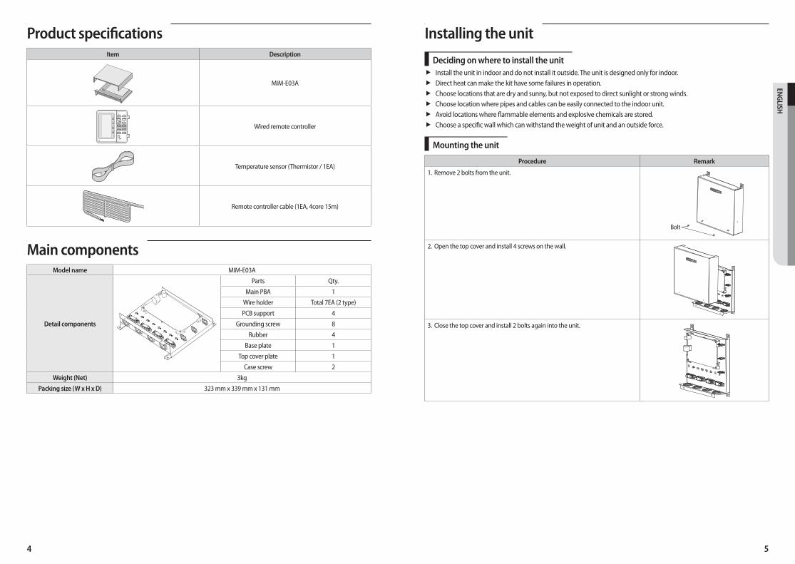
Installing the unit
Deciding on where to install the unitff Install the unit in indoor and do not install it outside. The unit is designed only for indoor.ff Direct heat can make the kit have some failures in operation. ff Choose locations that are dry and sunny, but not exposed to direct sunlight or strong winds.ff Choose location where pipes and cables can be easily connected to the indoor unit. ff Avoid locations where flammable elements and explosive chemicals are stored.ff Choose a specific wall which can withstand the weight of unit and an outside force.
Mounting the unit
Procedure Remark
1. Remove 2 bolts from the unit.
Bolt
2. Open the top cover and install 4 screws on the wall.
3. Close the top cover and install 2 bolts again into the unit.
Product specificationsItem Description
MIM-E03A
Wired remote controller
Temperature sensor (Thermistor / 1EA)
Remote controller cable (1EA, 4core 15m)
Main componentsModel name MIM-E03A
Detail components
Parts Qty.
Main PBA 1
Wire holder Total 7EA (2 type)
PCB support 4
Grounding screw 8
Rubber 4
Base plate 1
Top cover plate 1
Case screw 2
Weight (Net) 3kg
Packing size (W x H x D) 323 mm x 339 mm x 131 mm
6 7
ENG
LISH
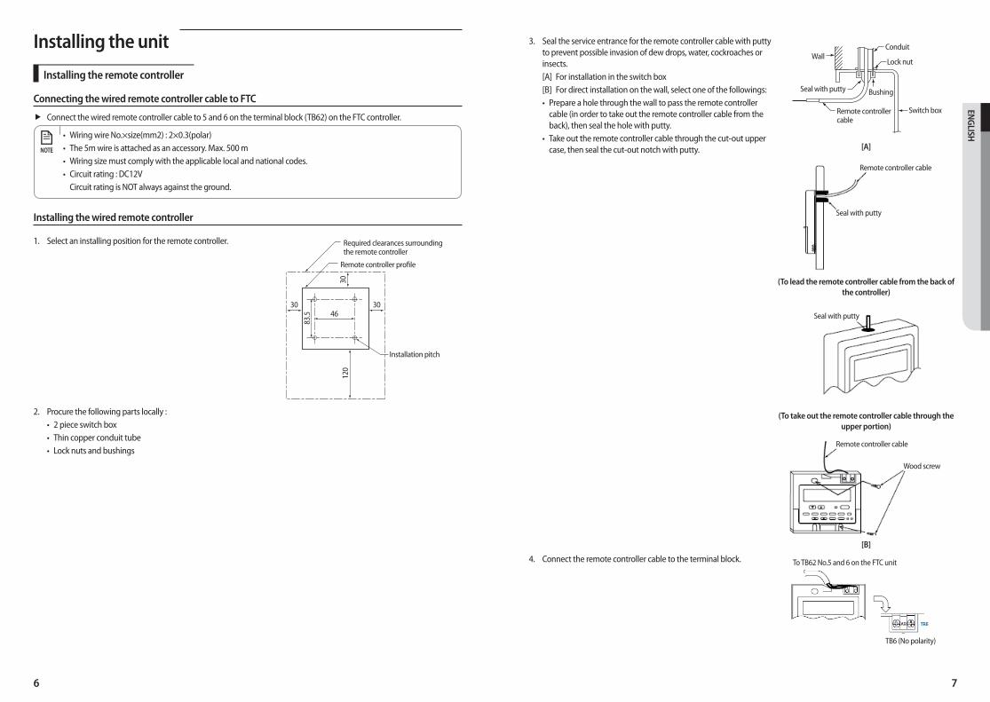
3. Seal the service entrance for the remote controller cable with putty to prevent possible invasion of dew drops, water, cockroaches or insects.[A] For installation in the switch box[B] For direct installation on the wall, select one of the followings:• Prepare a hole through the wall to pass the remote controller
cable (in order to take out the remote controller cable from the back), then seal the hole with putty.
• Take out the remote controller cable through the cut-out upper case, then seal the cut-out notch with putty.
Wall
Remote controller cable
Seal with putty
Conduit
Lock nut
Switch box
Bushing
[A]
Seal with putty
Remote controller cable
(To lead the remote controller cable from the back of the controller)
Seal with putty
(To take out the remote controller cable through the upper portion)
Remote controller cable
Wood screw
[B]
4. Connect the remote controller cable to the terminal block.
TB6 (No polarity)
To TB62 No.5 and 6 on the FTC unit
Installing the unit
Installing the remote controller
Connecting the wired remote controller cable to FTC
ff Connect the wired remote controller cable to 5 and 6 on the terminal block (TB62) on the FTC controller.
• Wiring wire No.×size(mm2) : 2×0.3(polar)• The 5m wire is attached as an accessory. Max. 500 m• Wiring size must comply with the applicable local and national codes.• Circuit rating : DC12V
Circuit rating is NOT always against the ground.
NOTE
Installing the wired remote controller
1. Select an installing position for the remote controller. Required clearances surrounding the remote controller
Installation pitch
Remote controller profile
30
83.5
120
3046
30
2. Procure the following parts locally :• 2 piece switch box• Thin copper conduit tube• Lock nuts and bushings
8 9
ENG
LISH
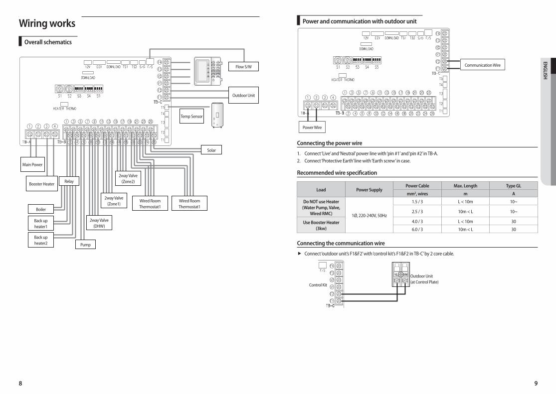
Power and communication with outdoor unit
Communication Wire
Power Wire
Connecting the power wire
1. Connect ‘Live’ and ‘Neutral’ power line with ‘pin #1’ and ‘pin #2’ in TB-A.2. Connect ‘Protective Earth’ line with ‘Earth screw’ in case.
Recommended wire specification
Load Power Supply Power Cable Max. Length Type GL
mm2, wires m A
Do NOT use Heater (Water Pump, Valve,
Wired RMC) 1Ø, 220-240V, 50Hz
1.5 / 3 L < 10m 10~
2.5 / 3 10m < L 10~
Use Booster Heater (3kw)
4.0 / 3 L < 10m 30
6.0 / 3 10m < L 30
Connecting the communication wire
ff Connect ‘outdoor unit’s F1&F2’ with ‘control kit’s F1&F2 in TB-C’ by 2 core cable.
Outdoor Unit (at Control Plate)
Control Kit
Wiring works
Overall schematics
Flow S/W
Outdoor Unit
Temp Sensor
Solar
Main Power
Relay
Pump
Booster Heater
Boiler
Back upheater1
Back upheater2
2way Valve(DHW)
2way Valve(Zone1)
2way Valve(Zone2)
Wired RoomThermostat1
Wired RoomThermostat1
10 11
ENG
LISH
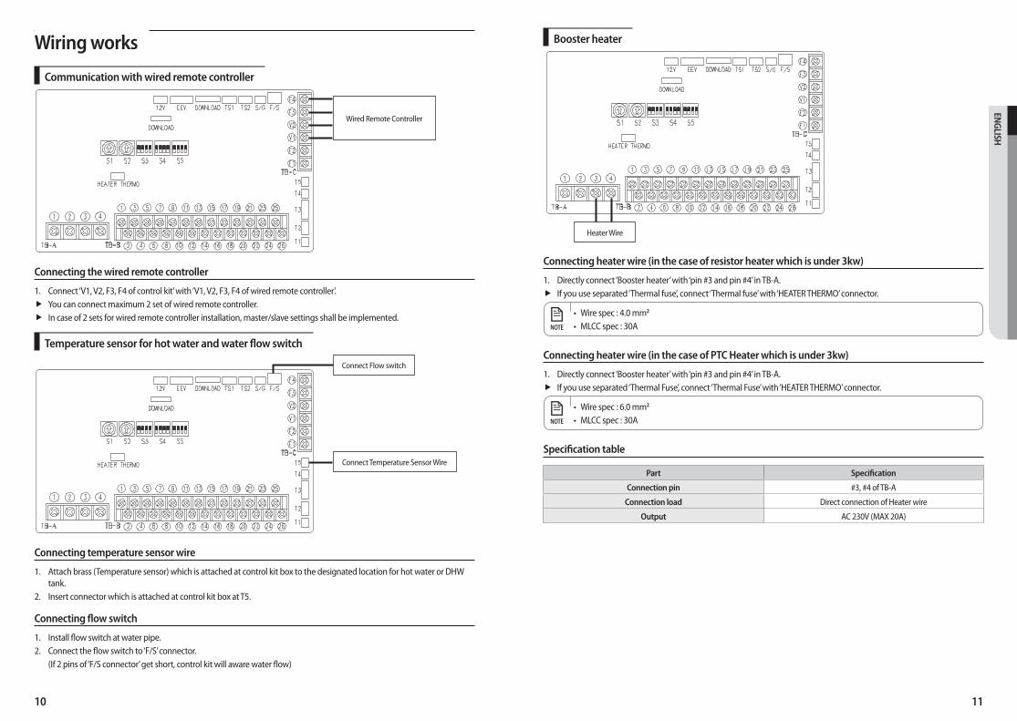
Booster heater
Heater Wire
Connecting heater wire (in the case of resistor heater which is under 3kw)
1. Directly connect ‘Booster heater’ with ‘pin #3 and pin #4’ in TB-A.ff If you use separated ‘Thermal fuse’, connect ‘Thermal fuse’ with ‘HEATER THERMO’ connector.
• Wire spec : 4.0 mm2
• MLCC spec : 30ANOTE
Connecting heater wire (in the case of PTC Heater which is under 3kw)
1. Directly connect ‘Booster heater’ with ‘pin #3 and pin #4’ in TB-A.ff If you use separated ‘Thermal Fuse’, connect ‘Thermal Fuse’ with ‘HEATER THERMO’ connector.
• Wire spec : 6.0 mm2
• MLCC spec : 30ANOTE
Specification table
Part Specification
Connection pin #3, #4 of TB-A
Connection load Direct connection of Heater wire
Output AC 230V (MAX 20A)
Wiring works
Communication with wired remote controller
Wired Remote Controller
Connecting the wired remote controller
1. Connect ‘V1, V2, F3, F4 of control kit’ with ‘V1, V2, F3, F4 of wired remote controller’.ff You can connect maximum 2 set of wired remote controller.ff In case of 2 sets for wired remote controller installation, master/slave settings shall be implemented.
Temperature sensor for hot water and water flow switch
Connect Temperature Sensor Wire
Connect Flow switch
Connecting temperature sensor wire
1. Attach brass (Temperature sensor) which is attached at control kit box to the designated location for hot water or DHW tank.
2. Insert connector which is attached at control kit box at T5.
Connecting flow switch
1. Install flow switch at water pipe.2. Connect the flow switch to ‘F/S’ connector.
(If 2 pins of ‘F/S connector’ get short, control kit will aware water flow)
12 13
ENG
LISH
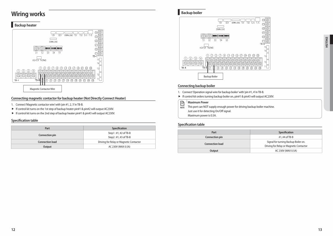
Backup boiler
Backup Boiler
Connecting backup boiler
1. Connect ‘Operation signal wire for backup boiler’ with ‘pin #1, 4’ in TB-B.ff If control kit orders turning backup boiler on, pin#1 & pin#3 will output AC230V.
Maximum PowerThis port can NOT supply enough power for driving backup boiler machine.Just use it for detecting On/Off signal.Maximum power is 0.5A.
NOTE
Specification table
Part Specification
Connection pin #1, #4 of TB-B
Connection load Signal for turning Backup Boiler on.
Driving for Relay or Magnetic Contactor
Output AC 230V (MAX 0.5A)
Wiring works
Backup heater
Magnetic Contactor Wire
Connecting magnetic contactor for backup heater (Not Directly Connect Heater)
1. Connect ‘Magnetic contactor wire’ with ‘pin #1, 2, 3’ in TB-B.ff If control kit turns on the 1st step of backup heater pin#1 & pin#2 will output AC230V.ff If control kit turns on the 2nd step of backup heater pin#1 & pin#3 will output AC230V.
Specification table
Part Specification
Connection pin Step1 : #1, #2 of TB-BStep2 : #1, #3 of TB-B
Connection load Driving for Relay or Magnetic Contactor
Output AC 230V (MAX 0.5A)

14 15
ENG
LISH
2way valve for hot water
2way valve (#1)
Connecting 2way valve (for hot water )
1. Directly connect ‘2way valve for ZONE.1’ with ‘pin #7, 8, 9, 10’ in TB-B.ff If control kit orders opening water pump on, pin#7 & pin#10 will output AC230V.
Maximum PowerThis port can supply power for small-medium sized valve.Maximum power is 0.5A(If total power consumption is over 2A, use relay or magnetic contactor)
NOTE
Specification table
Part Specification
Connection pin
#7 : Output Power N#8 : Output Power L
#9 : Output turning on Power (Normal Opened L line)#10 : Output turning on Power (Normal Closed L line)
Connection load Direct connect 2way valves (under 0.5A)
Output AC 230V (MAX 0.5A / 120W)
Wiring works
Water pump
Water Pump
Connecting water pump
1. Directly connect ‘water circulation pump’ with ‘pin #5, 6’ in TB-B.ff If control kit orders turning water pump on, pin#5 & pin#6 will output AC230V.
Maximum PowerThis port can supply power for small-medium sized water pump.Maximum power is 2A ( Total power consumption must be under 2A)(If total power consumption is over 2A, use relay or magnetic contactor)
NOTE
Specification table
Part Specification
Connection pin #5, #6 of TB-B
Connection load Direct connect water pump (under 2A)
Driving for Relay or Magnetic Contactor (over 2A)
Output AC 230V (MAX 2A)
16 17
ENG
LISH
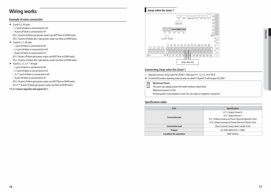
2way valve for zone 1
2way valve (#2)
Connecting 2way valve (for Zone1 )
1. Directly connect ‘2way valve for ZONE.1’ with ‘pin #11, 12, 13, 14’ in TB-B.ff If control kit orders opening water pump on, pin#11 & pin#13 will output AC230V.
Maximum PowerThis port can supply power for small-medium sized valve.Maximum power is 0.5A(If total power consumption is over 2A, use relay or magnetic contactor)
NOTE
Specification table
Part Specification
Connection pin
#11 : Output Power N#12 : Output Power L
#13 : Output turning on Power (Normal Opened L line)#14 : Output turning on Power (Normal Closed L line)
Connection load Direct connect 2way valves (under 0.5A)
Output AC 230V (MAX 0.5A / 120W)
Condition for operation (NOT Define)
Wiring worksExample of valve connection
ff 2 pole (L1, N) type• L1 port of Valve is connected to #10• N port of Valve is connected to #7(If L1, N ports of Valve get power, water can NOT flow to DHW tank.)(If L1, N ports of Valve don`t get power, water can flow to DHW tank.)ff 3 pole (L, L1, N) type
• L port of Valve is connected to #8• L1 port of Valve is connected to #10• N port of Valve is connected to #7(If L1, N port of Valve get power, water can NOT flow to DHW tank.)(If L1, N ports of Valve don`t get power, water can flow to DHW tank.)ff 4 pole (L, L1, /L1*1), N) type
• L port of Valve is connected to #8• L1 port of Valve is connected to #10• /L1*1) port of Valve is connected to #9• N port of Valve is connected to #7(If L1, N port of Valve get power, water can NOT flow to DHW tank.)(If /L1*1), N port of Valve get power, water can flow to DHW tank.)
*1) /L1 means opposite side signal of L1.
18 19
ENG
LISH
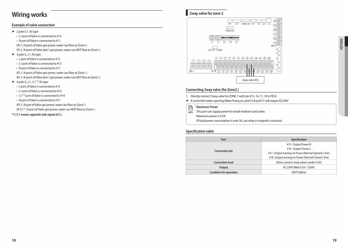
2way valve for zone 2
2way valve (#3)
Connecting 2way valve (for Zone2 )
1. Directly connect ‘2way valve for ZONE.1’ with ‘pin #15, 16, 17, 18’ in TB-B.ff If control kit orders opening Water Pump on, pin#15 & pin#17 will output AC230V.
Maximum PowerThis port can supply power for small-medium sized valve.Maximum power is 0.5A(If total power consumption is over 2A, use relay or magnetic contactor)
NOTE
Specification table
Part Specification
Connection pin
#15 : Output Power N#16 : Output Power L
#17 : Output turning on Power (Normal Opened L line)#18 : Output turning on Power (Normal Closed L line)
Connection load Direct connect 2way valves (under 0.5A)
Output AC 230V (MAX 0.5A / 120W)
Condition for operation (NOT Define)
Wiring worksExample of valve connection
ff 2 pole (L1, N) type• L1 port of Valve is connected to #13• N port of Valve is connected to #11(If L1, N ports of Valve get power, water can flow to Zone1.)(If L1, N ports of Valve don`t get power, water can NOT flow to Zone1.)ff 3 pole (L, L1, N) type
• L port of Valve is connected to #12• L1 port of Valve is connected to #13• N port of Valve is connected to #11(If L1, N ports of Valve get power, water can flow to Zone1.)(If L1, N ports of Valve don`t get power, water can NOT flow to Zone1.)ff 4 pole (L, L1, /L1*1), N) type
• L port of Valve is connected to #12• L1 port of Valve is connected to #13• /L1*1) port of Valve is connected to #14• N port of Valve is connected to #11(If L1, N port of Valve get power, water can flow to Zone1.)(If /L1*1), N port of Valve get power, water can NOT flow to Zone1.)
*1) /L1 means opposite side signal of L1.
20 21
ENG
LISH
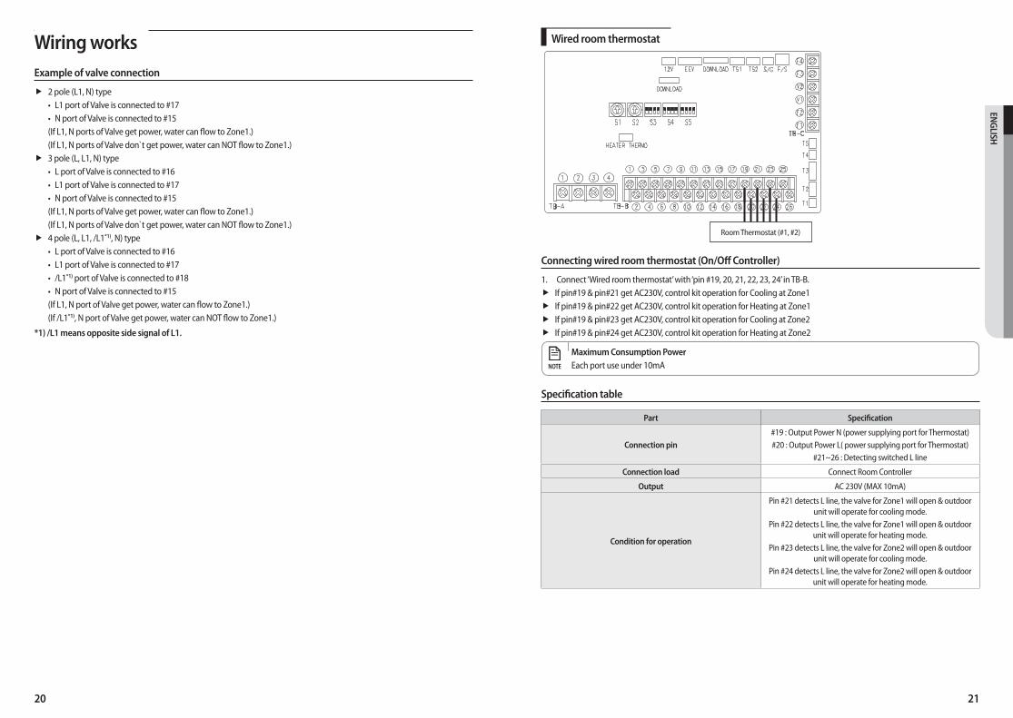
Wired room thermostat
Room Thermostat (#1, #2)
Connecting wired room thermostat (On/Off Controller)
1. Connect ‘Wired room thermostat’ with ‘pin #19, 20, 21, 22, 23, 24’ in TB-B.ff If pin#19 & pin#21 get AC230V, control kit operation for Cooling at Zone1ff If pin#19 & pin#22 get AC230V, control kit operation for Heating at Zone1ff If pin#19 & pin#23 get AC230V, control kit operation for Cooling at Zone2ff If pin#19 & pin#24 get AC230V, control kit operation for Heating at Zone2
Maximum Consumption PowerEach port use under 10mANOTE
Specification table
Part Specification
Connection pin #19 : Output Power N (power supplying port for Thermostat)#20 : Output Power L( power supplying port for Thermostat)
#21~26 : Detecting switched L line
Connection load Connect Room Controller
Output AC 230V (MAX 10mA)
Condition for operation
Pin #21 detects L line, the valve for Zone1 will open & outdoor unit will operate for cooling mode.
Pin #22 detects L line, the valve for Zone1 will open & outdoor unit will operate for heating mode.
Pin #23 detects L line, the valve for Zone2 will open & outdoor unit will operate for cooling mode.
Pin #24 detects L line, the valve for Zone2 will open & outdoor unit will operate for heating mode.
Wiring worksExample of valve connection
ff 2 pole (L1, N) type• L1 port of Valve is connected to #17• N port of Valve is connected to #15(If L1, N ports of Valve get power, water can flow to Zone1.)(If L1, N ports of Valve don`t get power, water can NOT flow to Zone1.)ff 3 pole (L, L1, N) type
• L port of Valve is connected to #16• L1 port of Valve is connected to #17• N port of Valve is connected to #15(If L1, N ports of Valve get power, water can flow to Zone1.)(If L1, N ports of Valve don`t get power, water can NOT flow to Zone1.)ff 4 pole (L, L1, /L1*1), N) type
• L port of Valve is connected to #16• L1 port of Valve is connected to #17• /L1*1) port of Valve is connected to #18• N port of Valve is connected to #15(If L1, N port of Valve get power, water can flow to Zone1.)(If /L1*1), N port of Valve get power, water can NOT flow to Zone1.)
*1) /L1 means opposite side signal of L1.
22 23
ENG
LISH
Setting option switches and function of keys
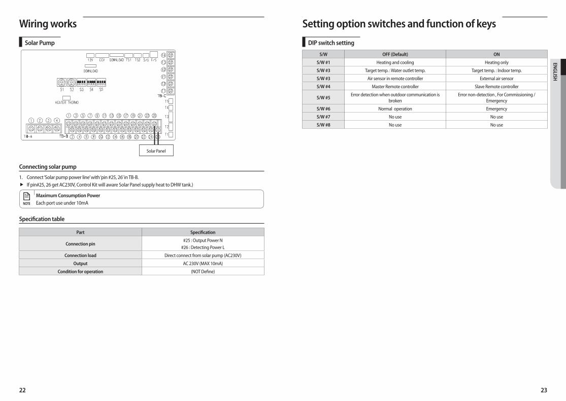
DIP switch setting
S/W OFF (Default) ON
S/W #1 Heating and cooling Heating only
S/W #3 Target temp. : Water outlet temp. Target temp. : Indoor temp.
S/W #3 Air sensor in remote controller External air sensor
S/W #4 Master Remote controller Slave Remote controller
S/W #5Error detection when outdoor communication is
brokenError non-detection , For Commissioning /
Emergency
S/W #6 Normal operation Emergency
S/W #7 No use No use
S/W #8 No use No use
Wiring works
Solar Pump
Solar Panel
Connecting solar pump
1. Connect ‘Solar pump power line’ with ‘pin #25, 26’ in TB-B.ff If pin#25, 26 get AC230V, Control Kit will aware Solar Panel supply heat to DHW tank.)
Maximum Consumption PowerEach port use under 10mANOTE
Specification table
Part Specification
Connection pin #25 : Output Power N
#26 : Detecting Power L
Connection load Direct connect from solar pump (AC230V)
Output AC 230V (MAX 10mA)
Condition for operation (NOT Define)
24 25
ENG
LISH
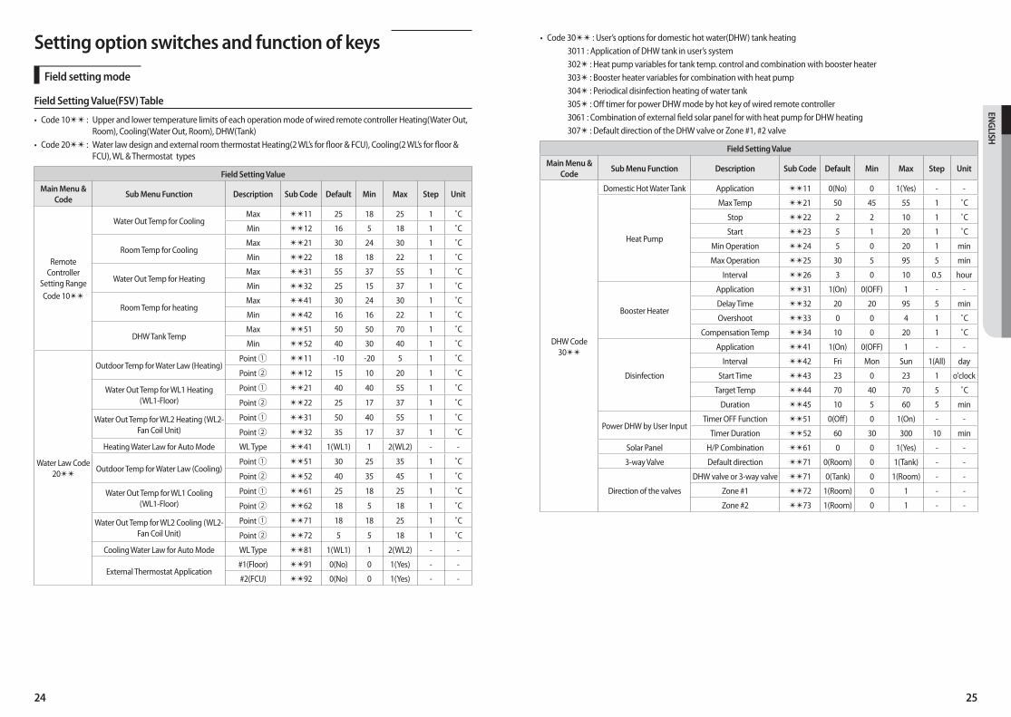
• Code 30✴✴ : User’s options for domestic hot water(DHW) tank heating 3011 : Application of DHW tank in user’s system 302✴ : Heat pump variables for tank temp. control and combination with booster heater 303✴ : Booster heater variables for combination with heat pump 304✴ : Periodical disinfection heating of water tank 305✴ : Off timer for power DHW mode by hot key of wired remote controller 3061 : Combination of external field solar panel for with heat pump for DHW heating 307✴ : Default direction of the DHW valve or Zone #1, #2 valve
Field Setting Value
Main Menu & Code
Sub Menu Function Description Sub Code Default Min Max Step Unit
DHW Code 30✴✴
Domestic Hot Water Tank Application ✴✴11 0(No) 0 1(Yes) - -
Heat Pump
Max Temp ✴✴21 50 45 55 1 ˚C
Stop ✴✴22 2 2 10 1 ˚C
Start ✴✴23 5 1 20 1 ˚C
Min Operation ✴✴24 5 0 20 1 min
Max Operation ✴✴25 30 5 95 5 min
Interval ✴✴26 3 0 10 0.5 hour
Booster Heater
Application ✴✴31 1(On) 0(OFF) 1 - -
Delay Time ✴✴32 20 20 95 5 min
Overshoot ✴✴33 0 0 4 1 ˚C
Compensation Temp ✴✴34 10 0 20 1 ˚C
Disinfection
Application ✴✴41 1(On) 0(OFF) 1 - -
Interval ✴✴42 Fri Mon Sun 1(All) day
Start Time ✴✴43 23 0 23 1 o'clock
Target Temp ✴✴44 70 40 70 5 ˚C
Duration ✴✴45 10 5 60 5 min
Power DHW by User InputTimer OFF Function ✴✴51 0(Off) 0 1(On) - -
Timer Duration ✴✴52 60 30 300 10 min
Solar Panel H/P Combination ✴✴61 0 0 1(Yes) - -
3-way Valve Default direction ✴✴71 0(Room) 0 1(Tank) - -
Direction of the valves
DHW valve or 3-way valve ✴✴71 0(Tank) 0 1(Room) - -
Zone #1 ✴✴72 1(Room) 0 1 - -
Zone #2 ✴✴73 1(Room) 0 1 - -
Setting option switches and function of keys
Field setting mode
Field Setting Value(FSV) Table
• Code 10✴✴ : Upper and lower temperature limits of each operation mode of wired remote controller Heating(Water Out, Room), Cooling(Water Out, Room), DHW(Tank)
• Code 20✴✴ : Water law design and external room thermostat Heating(2 WL’s for floor & FCU), Cooling(2 WL’s for floor & FCU), WL & Thermostat types
Field Setting Value
Main Menu & Code
Sub Menu Function Description Sub Code Default Min Max Step Unit
Remote Controller
Setting RangeCode 10✴✴
Water Out Temp for CoolingMax ✴✴11 25 18 25 1 ˚C
Min ✴✴12 16 5 18 1 ˚C
Room Temp for CoolingMax ✴✴21 30 24 30 1 ˚C
Min ✴✴22 18 18 22 1 ˚C
Water Out Temp for HeatingMax ✴✴31 55 37 55 1 ˚C
Min ✴✴32 25 15 37 1 ˚C
Room Temp for heatingMax ✴✴41 30 24 30 1 ˚C
Min ✴✴42 16 16 22 1 ˚C
DHW Tank TempMax ✴✴51 50 50 70 1 ˚C
Min ✴✴52 40 30 40 1 ˚C
Water Law Code 20✴✴
Outdoor Temp for Water Law (Heating)Point ① ✴✴11 -10 -20 5 1 ˚C
Point ② ✴✴12 15 10 20 1 ˚C
Water Out Temp for WL1 Heating (WL1-Floor)
Point ① ✴✴21 40 40 55 1 ˚C
Point ② ✴✴22 25 17 37 1 ˚C
Water Out Temp for WL2 Heating (WL2-Fan Coil Unit)
Point ① ✴✴31 50 40 55 1 ˚C
Point ② ✴✴32 35 17 37 1 ˚C
Heating Water Law for Auto Mode WL Type ✴✴41 1(WL1) 1 2(WL2) - -
Outdoor Temp for Water Law (Cooling)Point ① ✴✴51 30 25 35 1 ˚C
Point ② ✴✴52 40 35 45 1 ˚C
Water Out Temp for WL1 Cooling (WL1-Floor)
Point ① ✴✴61 25 18 25 1 ˚C
Point ② ✴✴62 18 5 18 1 ˚C
Water Out Temp for WL2 Cooling (WL2-Fan Coil Unit)
Point ① ✴✴71 18 18 25 1 ˚C
Point ② ✴✴72 5 5 18 1 ˚C
Cooling Water Law for Auto Mode WL Type ✴✴81 1(WL1) 1 2(WL2) - -
External Thermostat Application#1(Floor) ✴✴91 0(No) 0 1(Yes) - -
#2(FCU) ✴✴92 0(No) 0 1(Yes) - -
26 27
ENG
LISH
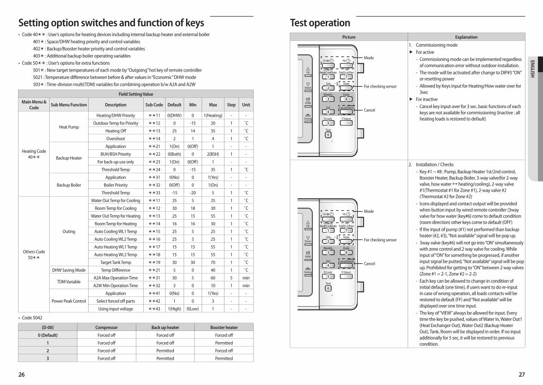
Test operationPicture Explanation
①
②
③ ⑧
④
⑤
⑥
⑦
For checking sensor
Mode
Cancel
1. Commissioning modeff For active
- Commissioning mode can be implemented regardless of communication error without outdoor installation.
- The mode will be activated after change to DIP#5 “ON” or resetting power
- Allowed by Keys input for Heating/How water over for 3sec
ff For inactive - Cancel key input over for 3 sec. basic functions of each
keys are not available for commissioning (Inactive : all heating loads is restored to default)
①
②
③ ⑧
④
⑤
⑥
⑦
For checking sensor
Mode
Cancel
2. Installation / Checks - Key #1 ~ #8 : Pump, Backup Heater 1st/2nd control,
Booster Heater, Backup Boiler, 3-way valve(for 2-way valve, how water ↔ heating/cooling), 2-way valve #1(Thermostat #1 for Zone #1), 2-way valve #2 (Thermostat #2 for Zone #2)
- Icons displayed and contact output will be provided when button input by wired remote controller (3way valve for how water (key#6) come to default condition (room direction) other keys come to default (OFF)
- If the input of pump (#1) not performed than backup heater (#2, #3), “Not available” signal will be pop up.
- 3way valve (key#6) will not go into “ON” simultaneously with zone control and 2 way valve for cooling. While input of “ON” for something be progressed, if another input signal be putted, “Not available” signal will be pop up. Prohibited for getting to “ON” between 2 way valves (Zone #1 = 2-1, Zone #2 = 2-2)
- Each key can be allowed to change in condition of initial default (one time), if users want to do re-input in case of wrong operation, all loads contacts will be restored to default (FF) and “Not available” will be displayed over one time input.
- The key of “VIEW” always be allowed for input. Every time the key be pushed, values of Water In, Water Out1 (Heat Exchanger Out), Water Out2 (Backup Heater Out), Tank, Room will be displayed in order. If no input additionally for 5 sec, it will be restored to previous condition.
Setting option switches and function of keys• Code 40✴✴ : User’s options for heating devices including internal backup heater and external boiler
401✴ : Space/DHW heating priority and control variables 402✴ : Backup/Booster heater priority and control variables 403✴ : Additional backup boiler operating variables
• Code 50✴✴ : User’s options for extra functions 501✴ : New target temperatures of each mode by “Outgoing” hot key of remote controller 5021 : Temperature difference between before & after values in “Economic” DHW mode 503✴ : Time-division multi(TDM) variables for combining operation b/w A2A and A2W
Field Setting Value
Main Menu & Code
Sub Menu Function Description Sub Code Default Min Max Step Unit
Heating Code 40✴✴
Heat Pump
Heating/DHW Priority ✴✴11 0(DHW) 0 1(Heating) - -
Outdoor Temp for Priority ✴✴12 0 -15 20 1 ˚C
Heating Off ✴✴13 25 14 35 1 ˚C
Overshoot ✴✴14 2 1 4 1 ˚C
Backup Heater
Application ✴✴21 1(On) 0(Off) 1 - -
BUH/BSH Priority ✴✴22 0(Both) 0 2(BSH) 1 -
For back-up use only ✴✴23 1(On) 0(Off) 1 - -
Threshold Temp ✴✴24 0 -15 35 1 ˚C
Backup Boiler
Application ✴✴31 0(No) 0 1(Yes) - -
Boiler Priority ✴✴32 0(Off) 0 1(On) - -
Threshold Temp ✴✴33 -15 -20 5 1 ˚C
Others Code 50✴✴
Outing
Water Out Temp for Cooling ✴✴11 25 5 25 1 ˚C
Room Temp for Cooling ✴✴12 30 18 30 1 ˚C
Water Out Temp for Heating ✴✴13 25 15 55 1 ˚C
Room Temp for Heating ✴✴14 16 16 30 1 ˚C
Auto Cooling WL1 Temp ✴✴15 25 5 25 1 ˚C
Auto Cooling WL2 Temp ✴✴16 25 5 25 1 ˚C
Auto Heating WL1 Temp ✴✴17 15 15 55 1 ˚C
Auto Heating WL2 Temp ✴✴18 15 15 55 1 ˚C
Target Tank Temp ✴✴19 30 30 70 1 ˚C
DHW Saving Mode Temp Difference ✴✴21 5 0 40 1 ˚C
TDM VariableA2A Max Operation Time ✴✴31 30 5 60 5 min
A2W Min Operation Time ✴✴32 3 0 10 1 min
Power Peak Control
Application ✴✴41 0(No) 0 1(Yes) - -
Select forced off parts ✴✴42 1 0 3 - -
Using input voltage ✴✴43 1(High) 0(Low) 1 - -
• Code 5042
[D-00] Compressor Back up heater Booster heater
0 (Default) Forced off Forced off Forced off
1 Forced off Forced off Permitted
2 Forced off Permitted Forced off
3 Forced off Permitted Permitted
28 29
ENG
LISH
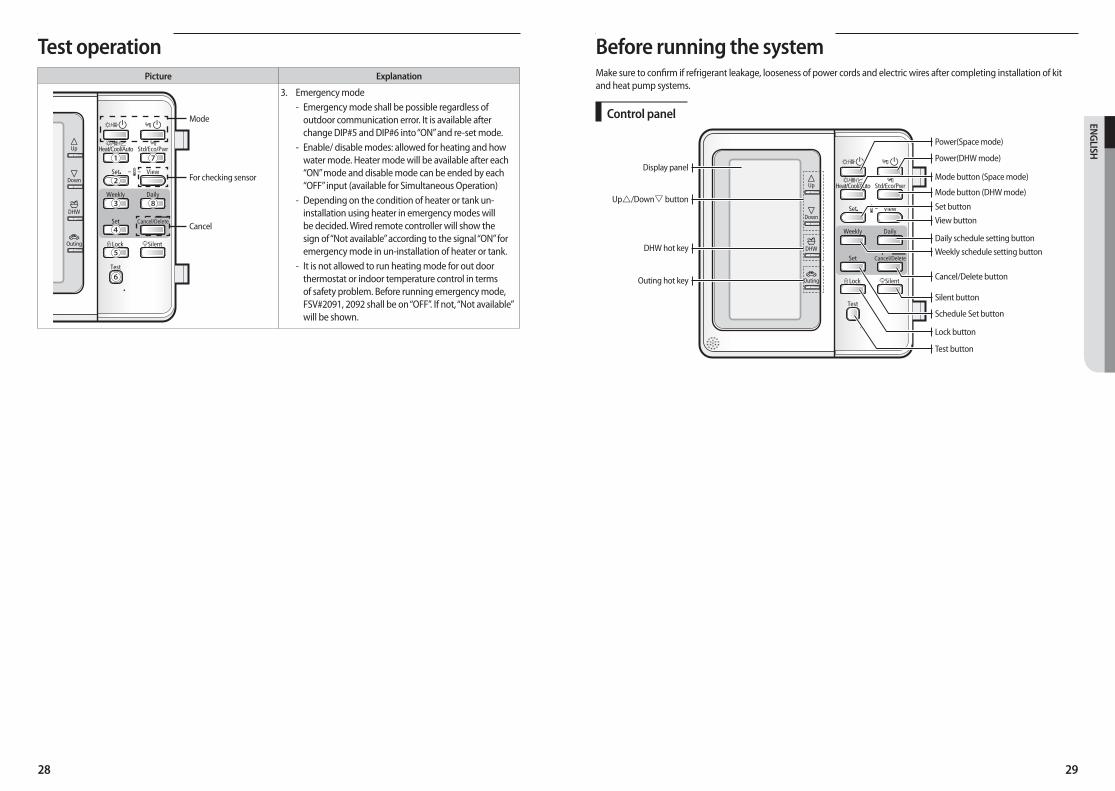
Before running the systemMake sure to confirm if refrigerant leakage, looseness of power cords and electric wires after completing installation of kit and heat pump systems.
Control panel
Display panel
Up/Down button
DHW hot key
Outing hot key
Power(Space mode)
Power(DHW mode)
Mode button (Space mode)
Mode button (DHW mode)
Set button
View button
Daily schedule setting button
Weekly schedule setting button
Cancel/Delete button
Silent button
Schedule Set button
Lock button
Test button
Test operationPicture Explanation
①
②
③ ⑧
④
⑤
⑥
⑦
For checking sensor
Mode
Cancel
3. Emergency mode - Emergency mode shall be possible regardless of
outdoor communication error. It is available after change DIP#5 and DIP#6 into “ON” and re-set mode.
- Enable/ disable modes: allowed for heating and how water mode. Heater mode will be available after each “ON” mode and disable mode can be ended by each “OFF” input (available for Simultaneous Operation)
- Depending on the condition of heater or tank un-installation using heater in emergency modes will be decided. Wired remote controller will show the sign of “Not available” according to the signal “ON” for emergency mode in un-installation of heater or tank.
- It is not allowed to run heating mode for out door thermostat or indoor temperature control in terms of safety problem. Before running emergency mode, FSV#2091, 2092 shall be on “OFF”. If not, “Not available” will be shown.
30 31
ENG
LISH
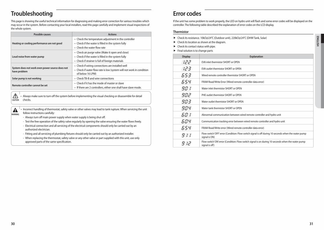
Error codesIf the unit has some problem to work properly, the LED on hydro unit will flash and some error codes will be displayed on the controller. The following table described the explanation of error codes on the LCD display.
Thermistor
ff Check its resistance. 10kΩ@24°C (Outdoor unit), 220kΩ@24°C (DHW Tank, Solar)ff Check its location as shown at the diagram.ff Check its contact status with pipe.ff Final solution is to change parts
Display Explanation
EVA inlet thermistor SHORT or OPEN
EVA outlet thermistor SHORT or OPEN
Wired remote controller thermistor SHORT or OPEN
FRAM Read/Write Error (Wired remote controller data error)
Water inlet thermistor SHORT or OPEN
PHE outlet thermistor SHORT or OPEN
Water outlet thermistor SHORT or OPEN
Water tank thermistor SHORT or OPEN
Abnormal communication between wired remote controller and hydro unit
Communication tracking error between wired remote controller and hydro unit
FRAM Read/Write error (Wired remote controller data error)
Flow switch ‘OFF’ error (Condition: Flow switch signal is off during 10 seconds when the water pump signal is ON)
Flow switch ‘ON’ error (Condition: Flow switch signal is on during 10 seconds when the water pump signal is off)
TroubleshootingThis page is showing the useful technical information for diagnosing and making error correction for various troubles which may occur in the system. Before contacting your local installers, read this page carefully and implement visual inspections of the whole system.
Possible causes Actions
Heating or cooling performance are not good
• Check the temperature adjustment in the controller• Check if the water is filled in the system fully• Check the water flow rate
Loud noise from water pump
• Check air purge valve (Make it open and close)• Check if the water is filled in the system fully• Check if strainer is full of foreign materials
System does not work even power source does not have problem
• Check if wiring connections are installed well• Check if water flow rate is low (system will not work in condition
of below 16 LPM)
Solar pump is not working • Check TB-B and wire connections
Remote controller cannot be set • Check if it has the mode of master or slave• If there are 2 controllers, either one shall have slave mode.
• Always make sure to turn off the system before implementing the visual checking or disassemble for detail checks. CAUTION
• Incorrect handling of thermostat, safety valve or other valves may lead to tank rupture. When servicing the unit follow instructions carefully: - Always turn off main power supply when water supply is being shut off. - Test the free operation of the safety valve regularly by opening the valve ensuring the water flows freely. - Electrical connection and all servicing of the electrical components should only be carried out by an
authorized electrician. - Fitting and all servicing of plumbing fixtures should only be carried out by an authorized installer. - When replacing the thermostat, safety valve or any other valve or part supplied with this unit, use only
approved parts of the same specification.
WARNING