sample of written materials ( - 778 kb)
TRANSCRIPT

RouterProgramming and Operation
Included in this sample package:> Brochure
Sales and pricing information about the curriculum
> Getting startedHow to use the curriculum
> Course outlineComplete outline of the entire course
> Sample lesson plansFor the first five lessons
> Sample of student manualFor the first key concept - lessons one through seven
> Sample of the workbookFor the first five lessons
Thank you for your interest in our CNC curriculums. There is quite a bit of information here, and weappreciate the time you’ll take to evaluate it. As you’ll see, our curriculums truly minimize the amount ofwork you’ll need to do to get ready to teach a CNC course.Our method of instruction is proven. It’s been developed during over ten years of actual CNC courses -and about half the schools listed in our schools forum (http://www.cncci.com/schools.htm) are using it.Again, there’s quite a bit of information here, so if you have questions, feel free to contact us at any time(email: [email protected] - or phone 847-639-8847).
CNC Cur ric u lums For CNC In struc tors!Ma chining Cen ter Pro gramming And Op er a tion t Turn ing Cen ter Pro gramming And Op er a tion
Teaching CNC has never been so easy!Our CNC cur ric u lums give you a proven,easy to use, con cise, yet com pre hen siveready-made train ing pro gram to min i -mize the prep a ra tion you must do toteach CNC courses. Right out of the boxyou get text books, work books, les sonplans, in struc tor notes, course out lines,an swers to prac tice ex er cises, and evensoft ware based slide show pre sen ta tions(in Microsoft Powerpoint vs 4.0) — ev ery -thing you need to ef fec tively teach CNCcourses for the two most pop u lar formsof CNC ma chine tools in ex is tence to day, CNC ma chin ing cen ters and CNCturn-ing cen ters.
They’re FREE with text book Or der!Not only will you be teach ing with thebest state-of-the-art CNC cur ric u lums inthe in dus try, you’ll be do ing so free ofcharge! All we ask is that your schoolbook store buys text books/work booksfrom us! With an ini tial or der of just 40text books, we’ll ship both com plete CNCcur ric u lums free! (20 for one cur ric u lum.)Any com bi na tion of ma chin ing cen ter or turn ing cen ter text books to tal ing 40 willqual ify. Text books are $50.00 each –work books are $14.95 each. Fu ture or -ders can be in any quan tity. This costwill be re cov ered, of course, as stu dentsen roll in your classes and buy text books. In es sence, your first 100 stu dents will be pay ing for these cur ric u lums!
Who will ben e fit?School teach ers work ing for ed u ca -tional in sti tu tions will find our course cur -ric u lums es pe cially easy to learn andim ple ment. Most CNC teach ers comefrom one of two back grounds. Ei therthey have ex ten sive CNC ex pe ri ence, but lim ited teach ing ex pe ri ence – or theyhave ex ten sive teach ing ex pe ri ence, butlim ited CNC ex pe ri ence. These coursecur ric u lums will help in both cases.
Our highly struc tured les son plans,text books, and slide show pre sen ta tionswill make it easy for even an in ex pe ri -enced teacher to stay on track. And thecom-prehensive in struc tor notes willmake ex pe ri enced teach ers who may bea lit tle weak with their CNC skills look likeCNC ex perts!
In struc tors work ing for man u fac tur -ing com pa nies will also find these cur ric -u lums very easy to im ple ment. Fewcom pa nies have the re sources or the de -sire to de velop this kind of pro gramcom-pletely from scratch. Ad di tionally,suc cess for this kind of pro gram is notsim ply a mat ter of the stu dent get ting a
good grade. Fail ure re sults in scrappedparts, crashed ma chines, and pos si bly in -jured op er a tors. The com pre hen sive stu -dent work book will prove the stu dent’sknowl edge of pre sented ma te ri als eachstep of the way. When the stu dent suc -cess fully com pletes one of these courses,you can rest as sured that they com pre -hend the sub ject mat ter.
Training con sul tants that pro videcus tom train ing for man u fac tur ing com -pa nies will find that this course cur ric u -lum makes it easy to teach CNC to theircli ents. Uti lizing stan dard (and highlypor ta ble) com puter equip ment, the com -pre hen sive slide show can be doneon-the-road, mean ing in struc tion cantake place any where there is a tele vi sion.
Proven Key Con ceptsap proachMost train ing ex perts agree that stu dentslearn best when they have a light at theend of the tun nel. The more com plexthe sub ject mat ter, the more im por tant itis that stu dents un der stand what theymust mas ter to suc cess fully com pletecourse. With our cur ric u lums, there areten key con cepts to CNC. The first six are pro gram ming-related and the last fourare op er a tion-related. Early in the course you can truth fully say “If you can un -der-stand just ten ba sic ideas, you arewell on your way to be com ing pro fi cientwith CNC.”
An other ben e fit of our key con ceptsap proach is that it lets you ex plain top icsat a broad level — which helps your stu -
dents get the big pic ture. With so many dif -fer ent CNC ma chine and con trol man u fac -tur ers, it’s im pos si ble to re late ev ery de tail of how each is han dled. For this rea son, stu -dents must have the abil ity to adapt whatthey learn to their own ma chines once theycom plete your course. In each key con cept, you first stress the broad and gen eral rea -son ing be hind how CNC func tions, show -ing stu dents why they must do things asim por tantly as how to do them. The samerea son ing can be ap plied to any form ofCNC ma chine tool.
Once the stu dent un der stands this rea -son ing, you show them spe cific tech niquesneeded to ap ply the key con cept to themost pop u lar CNC con trol in the in dus try. All of the spe cific ex am ples given in the text -book and slide show are for the Fanuc con -trol. We chose Fanuc as the ex am plecon trol since it is so pop u lar, and since sev -eral con trol man u fac tur ers (MitusbishiMeldas, Mazatrol, Yasnac, HAAS, Fadal, andoth ers) claim to be Fanuc-compatible.
Here are the ten Key Con cepts.Pro gramming
1 Know your ma chine (pro gram ming)2 Pre pare to write pro grams3 Un der stand the mo tion types4 Know the com pen sa tion types5 Know how to for mat CNC pro grams6 Spe cial pro gram ming fea tures
Op er a tion7 Know your ma chine (op er a tion)8 Know the three modes of op er a tion9 Know the key op er a tion pro ce dures 10 Know how to safely ver ify pro grams
For More In for ma tion, Call (847) 639-8847 44 Lit tle Cahill Road, Cary, IL 60013 CNC Con cepts, Inc.
From

Les son struc tureThe ten key con cepts are di vided fur therinto les sons. (24 les sons in the ma chin -ing cen ter cur ric u lum – 28 in the turn ing cen ter cur ric u lum.) Les sons vary inlength based upon com plex ity and con -tent (from 10 min utes to about an hour).
Ma chining cen ter cur ric u lum:1 Ma chine con fig u ra tions2 Gen eral flow of pro gram ming3 Vi su al izing pro gram ex e cu tion4 Un der stand ing pro gram zero5 Mea suring pro gram zero6 The 2 ways to as sign pro gram zero7 In tro duc tion to pro gram ming words8 Prep a ra tion for pro gram ming9 Mo tion types10 In tro duc tion to com pen sa tion11 Tool length com pen sa tion12 Cut ter ra dius com pen sa tion13 Fix ture off sets14 In tro duc tion to pro gram for mat ting15 The four kinds of pro gram for mat16 Canned cy cles17 Subprogramming tech niques18 Other special fea tures19 Ro tary ta bles20 The con trol panel21 The ma chine panel22 The three modes of op er a tion23 The key se quences of op er a tion24 Pro gram ver i fi ca tion
Turn ing cen ter cur ric u lum:1 Ma chine con fig u ra tion2 Speeds and feeds3 Vi su al izing pro gram ex e cu tion4 Un der stand ing pro gram zero5 Mea suring pro gram zero6 As signing pro gram zero7 Flow of pro gram pro cess ing8 In tro duc tion to pro gram ming words9 Prep a ra tion for pro gram ming10 Types of mo tion11 In tro duc tion to com pen sa tion
12 Di men sional (wear) tool off sets13 Ge om e try off sets14 Tool nose ra dius com pen sa tion15 Pro gram for mat ting16 The four kinds of pro gram for mat17 Sim ple canned cy cles18 Rough turn ing and bor ing cy cle19 More mul ti ple re pet i tive cy cles20 Threading mul ti ple re pet i tive cy cle21 Subprogramming tech niques22 Con trol model dif fer ences23 Other spe cial fea tures of pro gram -ming24 Con trol panel func tions25 Ma chine panel func tions26 Three modes of op er a tion27 The key op er a tion pro ce dures28 Ver ifying new pro grams safely
Stu dent coursema te ri alsStu dent course ma te ri als are copy rightedand must be pur chased di rectly fromCNC con cepts, Inc. A min i mum ini tialor-der of 100 sets will qual ify you to getthese cur ric u lums free of charge.
Stu dent text booksOur highly tu to rial text books pre cisely fol -lows the slide show pre sen ta tions youwill be mak ing. Each is very de tailed(over 250 pages) and will pro vide thestu dent with an ex cel lent way to re viewthe in for ma tion you pres ent — dur ingthe course and long af ter the course isfin-ished. Of course, as the in struc tor,you will also want to have one of theseman u als handy as you pres ent thecourse.
Stu dent work booksThese ex er cises will con firm that stu dentsun der stand your pre sen ta tionsthrough-out the course. There is one ex -er cise per les son.
In struc tor coursema te ri alsWhile we do not com pletely elim i natethe prep a ra tion you must do to getready to teach, we re ally min i mize it!
Dis kettes of Powerpointslide pre sen ta tionsThese dis kettes of highly com pressed files ex pand to about 16 mega bytes of highly col or ful, il lus tra tive, and at ten tion get ting Microsoft Powerpoint slide shows (over1,200 slides each!). To dis play these slideshows, we even in clude the PowerpointViewer (free dis tri bu tion copy). How -ever, in or der to mod ify these slideshows, you must have MicrosoftPowerpoint soft ware (ver sion 4.0 orhigher).
You have sev eral al ter na tives for pro -ject ing the slide shows for your class tosee. All in volve de vices that arecon-nected to the VGA dis play port ofyour com puter. First, many schools al -ready have a pro jec tion sys tem that candis play in for ma tion from a per sonal com -puter. Any thing that can be shown onthe com-puter screen (your slide show)can be dis played through the pro jec tionsys tem. Sec ond, you can use a de vicethat rests on top of an over head pro jec -tor to dis play your screen shows. Third,and es pe cially if price is a con cern, youcan use a sim ple scan con verter (about$200.00 - $300.00) to dis play yourscreen show on any tele vi sion that has avideo-in (RCA) con nec tor.
In struc tor Notes man u alsEs pe cially help ful the first few times youteach these courses, these man u als –one for each cur ric u lum – of fer manysug ges tions about how top ics should bepre sented. They make an ex cel lent wayto pre pare to de liver your pre sen ta tions.
Sim ply call up the pre sen ta tion inPowerpoint (or use the Slide Hard CopyMan-ual) to skim through the slides. Hav ing your In struc tor’s Notes Man ual handy whileyou do so will help you quickly in ter pretwhat must be said dur ing each les son.
Slide show hard copy man u alsThese man u als in clude all slides for eachcur ric u lum, help ing you to pre pare to de -liver each les son and help ing you find theslide num ber for key slides.
Course out linesThese out lines give you a con cise way toskim what you will be pre sent ing dur ing the course. Ad di tionally, they make an ex cel lent quick ref er ence for find ing the slide num -bers in each Powerpoint pre sen ta tion. Atthe end of each out line we also show theap prox i mate pre sen ta tion time you shouldal low for each les son.
Blank op er a tion hand booksIn the stu dent text book for each cur ric u lumis a sam ple op er a tion hand book for threeFanuc con trol mod els. These hand-bookswill pro vide stu dents with a good un der -stand ings of im por tant pro ce dures thatmust be doc u mented. How ever, you willneed to doc u ment these key pro ce duresfor the spe cific ma chines in your own fa cil -ity.
An swers to prac ticeex er cises man u alsThese an swers are pro vided to help yougrade the prac tices ex er cises you as signfrom the stu dent work book.
Fi nal testsThese tests (one for each cur ric u lum) willhelp you de ter mine each stu dent’s over allun der stand ing of sub ject mat ter at the com -ple tion of the course.
For More In for ma tion, Call (847) 639-8847 44 Lit tle Cahill Road, Cary, IL 60013 CNC Con cepts, Inc.

Getting StartedPage 1
Getting Started With The Curriculums:
These course curriculums have been designed to address the needs of instructors working inthree similar, but subtly different, learning environments. First, instructors working for colleges,vocational schools, technical schools, and universities will find our ready-made coursecurriculums especially easy to learn and implement. It has been our experience that instructorsteaching their first CNC courses for technical schools come from one of but two backgrounds.Either they have extensive CNC experience (possibly through working for a manufacturingcompany), but limited teaching experience --- or they have extensive teaching experience(teaching other courses for the school), but limited CNC experience. It is rare to find aninstructor who has extensive experience in both fields. These course curriculums will help inboth cases.
Our proven curriculums, structured lesson plans, and concise lesson format will minimize theamount of work an instructor must do in preparation for teaching a new course -- and minimizethe work that must be done when getting ready to teach each lesson during the course. Theproven key concepts approach makes it easy for even an inexperienced instructor to stay ontrack. And - the slide presentations & comprehensive student manuals will make experiencedinstructors who may be a little weak with their CNC skills look like CNC experts!
Second, instructors working for companies having their own in-plant training will also find thiscurriculum easy to implement. Few companies have the resources (or the desire) to completelydevelop this kind of program from scratch. Additionally, success for an industrial trainingprogram is not a simple a matter of the student getting a good grade. When finished, studentsmust know how to safely program and/or operate the machine tools. Training failure will resultin scrapped parts, crashed machines, and possibly even injured operators. The comprehensivestudent workbooks will prove the student’s knowledge of presented materials each step of theway. When the student successfully completes this course, you can rest assured that theycomprehend the subject matter.
Third, training consultants that provide custom training for manufacturing companies will find thatthis course curriculum makes it easy to teach CNC to their clients. Utilizing standard (and highlyportable) computer equipment, the comprehensive slide show can be done on-the-road,meaning instruction can take place anywhere.
Five factors that contribute to learningWhile experienced instructors may find this information somewhat basic, we wish to ensure thatbeginning instructors understand the importance of setting up a good learning environment. Ofcourse, the better the learning environment, the better the training program will be, and thefaster, and easier it will be for students to learn. This course curriculum is well suited tofacilitating the learning environment in all five ways.

Getting StartedPage 2
Motivation is the most important factor in any learning environment. First and foremost,students must be highly motivated to learn. Motivation will be the driving force that makesstudents stick with it even when they are having trouble understanding information beingpresented during training. Indeed, any problem with learning can be overcome if the student’smotivation is high enough. But just as important, the instructor must also be highly motivated toteach. They must have a burning desire to relate information during training in a way studentscan understand. When student are having problems, the instructor must be motivated enough tospend the extra time it takes to ensure that the student eventually understands presentedmaterial. This can be very challenging since students’ aptitude levels vary. This coursecurriculum inspires motivation on both counts. The colorful and illustrative slide show, thetutorial nature of the manual, the pertinent practice exercises, and the highly structured keyconcepts approach will capture and hold your students’ attention, and make it easy for them tostay motivated. For the same reasons, instructors should find this course almost fun to teach -and it is easy to stay motivated with tasks you enjoy.
Aptitude will determine how quickly and easily learning will be. The aptitude of the instructorfor making attention holding presentations, giving pertinent analogies, preparing illustrativevisuals, designing realistic practice exercises, and in general, keeping the students interested levelhigh will contribute to determining how quickly and easily students catch on to new material.Instructors with high aptitude make it easy for students to learn. In similar fashion, thestudents’ aptitude for learning manufacturing related functions and specifically CNC alsocontribute to how quickly and easily learning takes place. Students with high aptitude makeit easy for the instructor to teach. This course curriculum pays particular attention to troublespots. From our own teaching experience, we know where students with minimal aptitude tendto have the most problems and make ample analogies to keep even the most complex topics ofCNC as simple as possible to understand.
Presentation is the heart of training. The better the instructor prepares and delivers thepresentation, the easier it will be for students to learn. Presentation can consist of many things,including the instructor’s orations, demonstrations, simulations, overhead and projector slides,videos, and anything else that helps to convey an idea. This is the strong point of ourcurriculums. You will find it very easy to get your ideas across with but a small amount ofpreparation before delivering each lesson. While you still have to talk, the slide show andinstructor notes will make sure you know what to say!
Repetition reinforces a student’s understanding of learned information. Even students withextremely high aptitude will find it difficult to learn from presentations made only once. Alltraining sessions should begin with a review of recent presentations. Depending upon thefrequency and duration of each training session, entire sessions should, at times, be devoted toreviewing what students should already know.Reviews also help the instructor limit how much complex subject matter is presented duringeach session. Knowing that certain information will be reviewed, the instructor can avoid gettingtoo deep into complicated topics during the first time the information is presented. Only after

Getting StartedPage 3
students have a firm grasp of the basics will the instructor dive deeper and introduce morecomplicated variations. The slide shows really help with review. As you begin each session,you can easily call up the presentation/s made recently and quickly skim material to ensurecomprehension. For review purposes, you can even hide slides during reviews (withinPowerpoint) to keep from having to go through all but the most important slides.
Practice with reinforcement acts as the gauge to judge the success of training. Well designedpractice exercises should be realistic, forcing the student to do things in the same way they mustwhen training is completed. Reinforcement must come as the result of the students’ practice. Ifthe student demonstrates a firm understanding of the presented information, reinforcementshould praise the success. On the other hand, if practice exposes a student’s lack ofunderstanding, reinforcement should come in the form of repeated presentations, review, andmore practice, ensuring that the student eventually catches on. This course curriculum include acomprehensive set of practice exercises, as well as a final test, to confirm understanding eachstep of the way.
The key concepts approachMost training experts agree that students learn best when they have a light at the end of thetunnel. The more complex the subject matter, the more important it is to tell the student early inthe training program just what they must master to complete the course. One important benefitof our proven key concepts approach you can do just that. With our curriculum, there are tenkey concepts to CNC. Six of the key concepts are programming-related and the last four areoperation-related. Early on in the course you can truthfully say “If you can understand justten basic ideas, you are well on your way to becoming proficient with CNC.” This givesyour students a light at the end of the tunnel and makes learning CNC seem as easy as possible.Also, as you go through the course, students will know where they stand each step along theway.
Another benefit of our key concepts approach is that it lets you work at a very broad level.There are many different CNC machine and control manufacturers making this kind ofequipment. Though there are many commonalties in how basic machine utilization is doneamong current CNC machines, no two machines will be handled exactly the same. For thisreason, students will likely have to adapt to their own machines once they complete your course(especially if you teach in a technical school). In each key concept you will be stressing thebroad and general reasoning behind how CNC functions, showing students why they must dothings as importantly as how they do them. This reasoning can be applied to any form of CNCmachine tool. Once the student understands this reasoning, then you will show specifictechniques needed to apply the key concept to one very popular CNC control.
By the way, all of the specific examples we give in the manual and during the slide show are inthe format for a Fanuc control. We chose Fanuc as our sample control since it is the mostpopular control in the industry, and since several control manufacturers (Mitusbishi Meldas,Mazatrol, Yasnac, HAAS, Fadal, and others) claim to be Fanuc-compatible. However, you

Getting StartedPage 4
must be prepared for the possibility that your students will be working with a control made by amanufacturer that is not Fanuc-compatible. Again, rest assured that the key concepts apply toevery current CNC control on the market. Only the specific techniques needed to apply eachkey concept must change.
These same ten key concepts can be applied to any form of CNC machine tool. Our coursecurriculums have been developed around three popular forms of CNC machine tools – formetal cutting, the CNC machining center and CNC turning center – for woodworking, theCNC router (three separate curriculums). While this is the case, the same key concepts can beapplied to wire EDM machines, CNC turret punch presses, CNC lasers, and any other type ofCNC.
Yet another benefit (from an instructor’s standpoint) of the key concepts approach is that thecourse can end at any time once students understand the key concepts. One major problem inany training program is the limited time available for training. While manufacturing companiesmay have the luxury of extending a course if students are slow in picking up the material,technical schools commonly work on a very rigid time frame. If students are slow in picking upthe material and getting bogged down with the details of CNC machine utilization (asking manytime consuming questions), the course may end before you get through all the material. Whilethis presents a problem even with the key concepts approach, the effects of the problem aregreatly minimized. As long as students understand the reasoning behind each key concept, itwill be just a matter of time until they figure out the details. Given our extensive and highlytutorial course manual, any student with motivation will eventually figure it out (possibly after thecourse ends).
One last benefit we’ll mention for the key concepts approach is that it makes reviewing thematerial easy. Since there are only ten key concepts, they are easy to remember. You cansimply restate each key concept and ask pertinent questions to confirm your students retentionof material previously presented.
In the lesson plans, student manuals, and course outline, you will find detailed explanations ofwhat must be presented at each key point in the course. Here we simply list the ten keyconcepts.
Key concept: Description:1 Know your machine (from a programmer’s viewpoint)2 Prepare to write programs3 Understand the motion types4 Know the compensation types5 Format your programs in a safe, convenient, and efficient manner6 Know the special features of programming7 Know your machine (from an operator’s viewpoint)8 Understand the three modes of operation

Getting StartedPage 5
9 Know the procedures related to operation10 You must be able to verify programs safely
Lesson structureThese ten key concepts are divided further concise lessons. For the machining centercurriculum, there are twenty-four lessons. With the turning center curriculum, there are twenty-eight lessons. With the CNC router curriculum, there are twenty-three lessons. Lessons dovary in length (from about 10 minutes of presentation to about an hour), and you can find anapproximate time of presentation in the course outline.
Machining center curriculum lesson structureLesson:Description:
1 Machine configurations2 General flow of programming3 Visualizing program execution4 Understanding program zero5 Measuring program zero6 The two ways to assign program zero7 Introduction to programming words8 Preparation for programming9 Motion types10 Introduction to compensation11 Tool length compensation12 Cutter radius compensation13 Fixture offsets14 Introduction to program formatting15 The four kinds of program format16 Canned cycles17 Subprogramming techniques18 Other special features of programming19 Rotary tables20 The control panel21 The machine panel22 The three modes of operation23 The key sequences of operation24 Program verification
Turning center lesson structureLesson:Description:
1 Machine configuration2 Speeds and feeds3 Visualizing program execution4 Understanding program zero5 Measuring program zero
Getting StartedPage 6
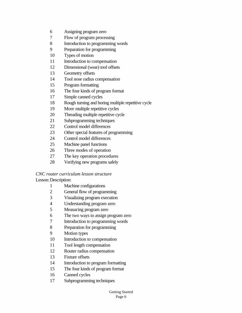
6 Assigning program zero7 Flow of program processing8 Introduction to programming words9 Preparation for programming10 Types of motion11 Introduction to compensation12 Dimensional (wear) tool offsets13 Geometry offsets14 Tool nose radius compensation15 Program formatting16 The four kinds of program format17 Simple canned cycles18 Rough turning and boring multiple repetitive cycle19 More multiple repetitive cycles20 Threading multiple repetitive cycle21 Subprogramming techniques22 Control model differences23 Other special features of programming24 Control model differences25 Machine panel functions26 Three modes of operation27 The key operation procedures28 Verifying new programs safely
CNC router curriculum lesson structureLesson:Description:
1 Machine configurations2 General flow of programming3 Visualizing program execution4 Understanding program zero5 Measuring program zero6 The two ways to assign program zero7 Introduction to programming words8 Preparation for programming9 Motion types10 Introduction to compensation11 Tool length compensation12 Router radius compensation13 Fixture offsets14 Introduction to program formatting15 The four kinds of program format16 Canned cycles17 Subprogramming techniques

Getting StartedPage 7
18 Other special features of programming19 The control panel20 The machine panel21 The three modes of operation22 The key sequences of operation23 Program verification
Student’s Course Materials:All student course materials are copyrighted and must be purchased from CNC concepts, Inc.Pricing is given on the order form that accompanies this document.
Student Manuals - These highly tutorial manuals precisely follows the slide show presentationsyou will be making. They are very detailed and will provide the student with an excellent way toreview information you present, during the course and long after the course is finished. There isone student manual for each curriculum. Of course, you will also want to have these manuals touse as your master as you present the course.
Student workbooks - This is the set of practice exercises students will be doing during thecourse. There is one exercise for each lesson (24 exercises for the machining center curriculum,28 exercises for the turning center curriculum, and 23 exercises for the CNC router curriculum).The practice exercises are like quizzes – you can use them as such or assign them ashomework. About half of the practice exercises additionally require the student to do aprogramming activity.
Instructor’s Course Materials:PowerPoint Viewer diskette - We strongly recommend that you purchase MicrosoftPowerPoint (version 4.0 or higher). This will give you total access to all slide showpresentations, making it possible for you to add, modify, or delete anything during the slideshows, and custom tailor these curriculums to your liking. However, if you do not haveMicrosoft PowerPoint, you can use the PowerPoint Viewer to display slide shows. Note thatboth the PowerPoint Viewer and PowerPoint itself require Microsoft Windows (version 3.1 orhigher). To load PowerPoint Viewer, place this disk in the drive A, select RUN from the FILEmenu of Windows, type A:\setup, and press enter. Follow the on-screen instructions tocomplete the install.
Diskettes of PowerPoint Slide Presentations - These disks of highly compressed files willexpand to about 10 megabytes for each curriculum on your hard drive. All presentation fileswill be placed in two subdirectories on your hard drive. For the machining center course, asubdirectory named \MCPO will be automatically created under your root directory. For theturning center course, a subdirectory named \TCPO will be created. For the CNC routercourse, a subdirectory named \RPO will be created. To load these files to your C:\ drive, placethe appropriate diskette (for machining center or turning center curriculum) in the drive and typeGO, then press enter. If you wish the files to be loaded to D:\, type GO_D instead (with
Getting StartedPage 8
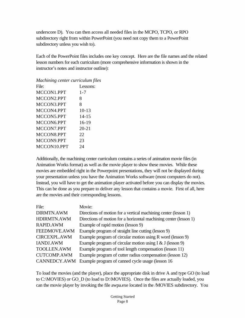
underscore D). You can then access all needed files in the MCPO, TCPO, or RPOsubdirectory right from within PowerPoint (you need not copy them to a PowerPointsubdirectory unless you wish to).
Each of the PowerPoint files includes one key concept. Here are the file names and the relatedlesson numbers for each curriculum (more comprehensive information is shown in theinstructor’s notes and instructor outline):
Machining center curriculum filesFile: Lessons:MCCON1.PPT 1-7MCCON2.PPT 8MCCON3.PPT 8MCCON4.PPT 10-13MCCON5.PPT 14-15MCCON6.PPT 16-19MCCON7.PPT 20-21MCCON8.PPT 22MCCON9.PPT 23MCCON10.PPT 24
Additionally, the machining center curriculum contains a series of animation movie files (inAnimation Works format) as well as the movie player to show these movies. While thesemovies are embedded right in the Powerpoint presentations, they will not be displayed duringyour presentation unless you have the Animation Works software (most computers do not).Instead, you will have to get the animation player activated before you can display the movies.This can be done as you prepare to deliver any lesson that contains a movie. First of all, hereare the movies and their corresponding lessons.
File: Movie:DIRMTN.AWM Directions of motion for a vertical machining center (lesson 1)HDIRMTN.AWM Directions of motion for a horizontal machining center (lesson 1)RAPID.AWM Example of rapid motion (lesson 9)FEEDMOVE.AWM Example program of straight line cutting (lesson 9)CIRCEXPL.AWM Example program of circular motion using R word (lesson 9)IANDJ.AWM Example program of circular motion using I & J (lesson 9)TOOLLEN.AWM Example program of tool length compensation (lesson 11)CUTCOMP.AWM Example program of cutter radius compensation (lesson 12)CANNEDCY.AWM Example program of canned cycle usage (lesson 16
To load the movies (and the player), place the appropriate disk in drive A and type GO (to loadto C:\MOVIES) or GO_D (to load to D:\MOVIES). Once the files are actually loaded, youcan the movie player by invoking the file awpa.exe located in the /MOVIES subdirectory. You

Getting StartedPage 9
can do this from the Windows file manager or from the Run selection from the file mode inWindows.
Turning center curriculum filesFile: Lessons:TCCON1.PPT 1-8TCCON2.PPT 9TCCON3.PPT 10TCCON4.PPT 11-14TCCON5.PPT 15-16TCCON6.PPT 17-23TCCON7.PPT 24-25TCCON8.PPT 26TCCON9.PPT 27TCCON10.PPT 28
CNC router curriculum filesFile: Lessons:RCON1.PPT 1-7RCON2.PPT 8RCON3.PPT 8RCON4.PPT 10-13RCON5.PPT 14-15RCON6.PPT 16-18RCON7.PPT 19-20RCON8.PPT 21RCON9.PPT 22RCON10.PPT 23
Additionally, the CNC router curriculum contains a series of animation movie files (in AnimationWorks format) as well as the movie player to show these movies. To display these movies, firstactivate the animation player. This can be done as you prepare to deliver any lesson thatcontains a movie. Here are the movies and their corresponding lessons.
File: Movie:RAPID.AWM Example of rapid motion (lesson 9)FEEDMOVE.AWM Example program of straight line cutting (lesson 9)CIRCEXPL.AWM Example program of circular motion using R word (lesson 9)IANDJ.AWM Example program of circular motion using I & J (lesson 9)TOOLLEN.AWM Example program of tool length compensation (lesson 11)CUTCOMP.AWM Example program of cutter radius compensation (lesson 12)CANNEDCY.AWM Example program of canned cycle usage (lesson 16

Getting StartedPage 10
To load the movies (and the player), place the appropriate disk in drive A and type GO (to loadto C:\MOVIES) or GO_D (to load to D:\MOVIES). Once the files are actually loaded, youcan the movie player by invoking the file awpa.exe located in the /MOVIES subdirectory. Youcan do this from the Windows file manager or from the Run selection from the file mode inWindows.
Lesson plans - We offer several methods to help you prepare to teach each lesson. Lessonplans (found at the end of this document), will make it easy to understand the key points youmust make in order to complete each lesson. In almost every plan, we also offer suggestionsabout how you can further clarify your points right at your own CNC machine/s. Finally, weoffer many suggestions regarding how you can review information and extend the students’understanding once they begin to catch on to basic points.
Instructor’s Notes Manuals - While you may find the lesson plans to be sufficient, we alsooffer many suggestions about how this course can be presented in the instructor notes. It willhelp you prepare to deliver each lesson and help you locate key slides in the presentation.While these course curriculums dramatically reduce the preparation you must do, we do notcompletely eliminate it. Until you become very comfortable with the course curriculum, westrongly recommend preparing to deliver each lesson. The best way to do so is to call up thepresentation in Powerpoint and to skim through the slides. Or if you don’t want to fire up thecomputer, use the Slide Presentation Hard Copy manual to go through the slides. Skimming theInstructor’s Notes manual while you do so will help you quickly interpret what must be saidduring each presentation. As you become more comfortable with the curriculum, you may beable to simply skim the instructor’s notes relative to each lesson to get ready to deliver eachlesson.
Slide Presentation Hard Copy Manual - These manuals provide you with a quick way toskim each slide in every lesson. Organized by file name (MCCON1.PPT, MCCON2.PPT,MCCON3.PPT, etc.), you’ll be able to see exactly what is shown during the yourpresentations. This should help you as you prepare to deliver each lesson.
Instructor’s Outline - Included at the end of this document, this outline gives you a conciseway of seeing what you will be presenting during the course. The lessons related to each keyconcept can be easily determined. Additionally, it makes a quick reference for finding the slidenumbers in the PowerPoint presentations. At the end of the instructor outline we also give youapproximate times you should allow to make presentations for each lesson.
Sample Operation Handbooks - At the end of each Student Manual is included a sampleoperation handbook for three Fanuc control models (10M, 11M, and 15M for the machiningcenter curriculum and 10T, 11T, and 15T for the turning center curriculum). This handbook willprovide students with a good understandings of important procedures that must be documented.

Getting StartedPage 11
Blank Operation Handbooks - It is very likely that you do not have one of these controls inyour own facility. For this reason, we give you the ability to develop your own operationhandbook for the machine/s you do have.
Answers To Practice Exercises Manuals - These answers are provided to help you gradeyour students performance.
Final Test - This test can be found at the end of this document along with the answers.
What you still need:In order to show the PowerPoint slide presentations to a group of people, you need thefollowing items.
A computer with Windows 3.1 (or higher) - Just about any current model computer willwork. For best results, a 486 or Pentium class is recommended (minimum 4 megs internal). Ifusing a desktop computer, you can easily watch the monitor of the computer (facing youraudience) to see the slide show as slides are displayed behind you by the projection system.Since the left mouse button advances the slides, you even have a remote slide advance button(as is commonly used with a 35 mm slide projector). If portability is an issue, keep in mind thatmany of the notebooks and sub-notebooks have ample power to run the presentation software.However, be careful in your selection. Many notebooks do not allow you to send data outthrough the VGA port and see the slide show on the LCD screen of the notebook at the sametime. Without this ability, you may have to turn around to see your slides, which can bedistracting to your audience.
Microsoft PowerPoint Software (version 4.0 was used to create the slide show) - Thoughyou can display all presentations with PowerPoint Viewer (included with this curriculum), youwill need Microsoft PowerPoint if you intend to modify the slide shows given in this curriculum.We highly recommend that you have this ability. This software can be found in any computerstore for a price of about $250.00 (it also comes with Microsoft Office). You will find this tobe a very powerful presentation generating program; one you can use to develop your own slideshows for other courses (or of course, modify those in this course curriculum).
A way of displaying the screen show - You have several alternatives in this regard. Allinvolve using a device that takes data from the VGA port of your personal computer. First,many schools already have a projection system that can display information from a personalcomputer. Basically, anything that can be shown on the computer screen can be displayedthrough the projection system. Second, you can use a device that sits on top of an overheadprojector to display your screen shows. In essence, this device makes a transparency of whatever is on the display screen of the computer. Third, and especially if price is a concern, youcan use a simple scan converter (about $200.00 - $300.00) and display your screen show onany television that has a video in connector (as most do). If you must use the RF connector ofthe television (where an antenna plugs in), an RF converter must be purchased. Since there are

Getting StartedPage 12
so many alternatives for displaying your slide shows, we welcome phone calls (847) 639-8847if you have questions about your alternatives.

Getting StartedPage 13
Putting It All Together
Getting Ready To TeachAs stated earlier, though these course curriculums dramatically reduce the amount ofpreparation you must do, they do not eliminate it completely. And as any experienced instructorwill agree, the key to successful presentations is in becoming comfortable with the material youpresent. And the only way to get comfortable is through adequate preparation.
Before your first course:Skim the entire curriculum - Though you do not have to be perfectly comfortable with everydetail of the curriculum to begin teaching, you will at least need to understand where the courseis going. You can use the course outline, lesson plans, instructor notes, and student manual togain an appreciation for the ten key concepts and the lesson structure being used.
Before beginning each key concept:Get comfortable will all lessons in the key concept - While some key concepts have butone lesson, most have more. Be sure you feel comfortable with all points you need to makebefore you begin teaching. Again, use the course outline, instructor notes, and student manualto increase your comfort level with the entire concept.
Before you deliver a lesson:Get ready to teach! - Study the lesson plan, instructor notes, and slide presentation hard copyin order to gain an understanding of key points that must be delivered during your presentation.
Practice! - Especially before your first few lessons, get comfortable with your equipment andthe material you present by practicing your presentation. In addition to getting you ready todeliver each lesson, this should give you a rough idea of how long it will take to deliver eachlesson.
During your presentation of each lesson:Tell them what you’re going to tell them - The lesson plan (key points in the slide show atthe beginning of each lesson) will help you prepare your students for what they will be learning.While you don’t have to dwell on this slide too long, it will help them know what is coming up.
Tell them - Go though the lesson, using your slide show as a guide. Be sure to point out thepage numbers and sections in the student manual where the information is also included for theirown independent study. Be sure everyone is catching on. Encourage participation, questions,and comments. While you should find adequate analogies in the slide show to stress the mostcomplex topics, you must be prepared to handle special questions and concerns. Have ablackboard or overhead available for making special points.
Getting StartedPage 14
Tell them what you told them - The lesson summary (included in the slide show for eachlesson) will let you summarize the key points of each lesson.
After you finish each lesson:Assign and check practice exercises - The students’ responses to the practice exercisesmakes an excellent way to gauge your students’ understanding of the subject matter. If you findthat students are not doing well, it should be taken as a signal that you must review keyinformation. If students are doing well, be sure to praise them.
As you get deeper into the course:Review often - No student will retain every word of every presentation you make during acourse as lengthy as these. On average, you should spend about 10% to 20% of your sessiontime in review, depending upon how well your students are doing. The more problems they arehaving, the more time you should spend on review. One excellent way to review is to questionstudents from the previous exercises to confirm their retention.
Let students know where they stand - Be sure everyone knows how they are doing as theyprogress through the course. Assign special exercises and labs for those students having themost problems. Push those students doing well to go further.

IN STRUC TOR OUT LINE FOR ROUTER PRO GRAMMING & OP ER A TION
Sec tion one - Pro gramming
Slide: De scrip tion (MCCON1.PPT): 1 Key con cept num ber one - know your ma -
chine7 Les son struc ture
Les son 1 - Ma chine con fig u ra tions 15 Les son plan16 Ba sic ma chin ing prac tice dis cus sion27 Ver ti cal ma chin ing cen ters28 Com po nents33 Direcitons of mo tion35 Hor i zon tal ma chin ing cen ters36 Com po nents41 Di rec tions of mo tion52 Other pro gram ma ble fea tures of ma chin ing
cen ters53 Les son 1 sum maryLes son 2 - Gen eral flow of pro gram ming 55 Les son plan57 Get the big pic ture59 De ci sion is made as to which CNC ma chine
to use60 The ma chin ing pro cess is de vel oped61 Tooling is or dered and checked62 The pro gram is de vel oped63 Set up doc u men ta tion is made64 Pro gram loaded into the CNC con trol65 The set up is made66 The pro gram is cau tiously ver i fied67 Pro duc tion is run68 Cor rected ver sion of the pro gram is stored
for fu ture use69 Les son 2 sum mary
Les son 3 - Vi su al izing the ex e cu tion of a CNC pro gram 72 Les son plan73 Anal ogy to giv ing a set of in struc tions91 Pro gram make-up92 Com mand struc ture97 Word struc ture104 Se quen tial method of pro gram ex e cu tion105 Vi su al izing move ments127 Other notes about pro gram struc ture128 Dec i mal point pro gram ming133 Dec i mal point omis sion134 Modal words136 Ini tial ized words138 Word or der within a com mand140 Les son 3 sum mary
Slide: De scrip tion (MCCON1.PPT):Les son 4 - Un der stand ing pro gram zero and the rect an -gu lar co or di nate sys tem 143 Les son plan144 What is pro gram zero?145 Graph anal ogy148 Base lines149 Or i gin of graph150 Axes of a ma chin ing cen ter162 XY plane164 In cre ments of each axis165 Plus and mi nus co or di nates167 XZ plane169 Ex am ple of co or di nates rel a tive to pro gram
zero178 Ex am ple of co or di nates in Z181 Where to place the pro gram zero point201 Un der stand ing the in cre men tal mode212 Ad van tages of the ab so lute mode215 In cre men tal warn ing219 Les son 4 sum mary
Les son 5 - Mea suring the pro gram zero point 222 Les son plan223 Why pro gram zero must be mea sured228 What is zero re turn po si tion?233 How the mea sure ment is made234 For rect an gu lar workpieces in the X and Y
axis255 For round workpieces in the X and Y axis266 For the Z axis276 How to avoid pro gram zero mea sure ments277 Les son 5 sum mary
Les son 6 - The two ways to as sign pro gram zero 280 Les son plan281 Lim i ta tions of older con trols283 As signing pro gram zero in the pro gram286 Po lar ity of di men sions291 The G92 com mand294 The ma jor prob lem with G92299 A safety com mand for use with G92300 As signing pro gram zero with fix ture off sets302 Po lar ity of di men sions307 The fix ture off set page of the dis play screen310 Com mands re lated to fix ture off sets311 How fix ture off sets are pro grammed312 Ad van tages of fix ture off sets313 Safety314 Mul ti ple workpieces
CNC Concepts, Inc. Machining Center Programming and Operation Page 1

Slide: De scrip tion (MCCON1.PPT):315 Re running tools316 Ef fi ciency320 Les son 6 sum mary
Les son 7 - In tro duc tion to pro gram ming words (323 Les son plan324 How many words are used?327 O word328 N word329 G word330 X word332 Y word333 Z word335 A, B, & C words336 R word338 I, J, & K words339 Q word340 P word343 L word345 F word346 S word347 T word348 M word349 D word350 H word351 End of block (EOB) word352 Slash (/) code353 Points about G words357 Points about M codes360 Points about other pro gram ming words364 Les son sum mary
Key con cept num ber two - Prep a ra tion for pro gram -ming (MCCON2.PPT)
Les son 8 - The im por tance or prep a ra tion 2 Les son plan3 In tro duc tion to key con cept num ber two4 Prep a ra tion and safety14 Steps for pre par ing to write a CNC pro gram22 Pre pare the ma chin ing pro cess23 Rea sons to do the pro cess up-front30 Do the re quired math and mark-up the print31 Mark ing up the print32 Doing the math33 Check the re quired tool ing38 Plan the set-up40 Les son sum mary
Slide: De scrip tion (MCCON3.PPT):Key con cept num ber three - Types of mo tion com -
mands (MCCON3.PPT)
Les son 9 The three kinds of mo tion 2 Les son plan3 In tro duc tion to key con cept num ber three4 What Is In ter po la tion? 7 Lin ear in ter po la tion in tro duc tion8 Cir cu lar in ter po la tion in tro duc tion9 He li cal in ter po la tion in tro duc tion10 The four types of mo tion15 Com mon func tions of all mo tion types21 Un der stand ing the point be ing pro grammed62 G00 Rapid mo tion (also called po si tion ing)37 Ex am ples of rapid39 G01 lin ear in ter po la tion (straight line mo tion)44 Ex am ple pro gram show ing straight line mo -
tion46 G02 and G03 Cir cu lar mo tion com mands53 Ex am ple pro gram show ing cir cu lar mo tion55 Using di rec tional vec tors (I, J, & K)56 I, J, & K de fined57 Ex am ples of I, J, & K59 Ex am ple pro gram us ing I, J, & K61 Arc lim i ta tions71 Making a full cir cle in one com mand74 Ex am ple of full cir cles in one com mand78 Ex am ple pro gram mak ing full cir cle87 He li cal mo tion87 Ex am ple of mo tion88 Les son sum mary
Key con cept num ber four -The three kinds of com pen -sa tion (MCCON4.PPT)
Les son 10 - In tro duc tion to com pen sa tion2 Les son plan3 In tro duc tion to key con cept num ber four10 Rea sons for com pen sa tions15 Marks man anal ogy20 Un der stand ing off sets22 The off set pages of the con trol24 In stating off sets29 Les son summarLes son 11 - Tool length com pen sa tion 32 Les son plan33 In tro duc tion to tool length com pen sa tion36 The rea son for tool length com pen sa tion48 Pro gramming words for tool length com pen -
sa tion54 When to in state59 Ex am ple com mands to in state
Time Out line
Page 2 Machining Center Programming and Operation CNC Concepts, Inc.

Slide: De scrip tion (MCCON4.PPT):61 Do you need to can cel?63 The two meth ods to use tool length
com pen sa tion69 Using the tool length as the off set76 How to mea sure the tool length on the
ma chine90 How to mea sure tool lengths off line94 Sum mary of key points100 Ex am ple pro gram show ing tool length
com pen sa tion102 Using the dis tance from the tool tip to
pro gram zero as the off set108 How to mea sure the off set121 Ad van tages of method num ber one (tool
length as off set)125 Fi nal notes about tool length com pen sa tion129 Les son sum mary
Les son 12 - Cut ter ra dius com pen sa tion132 Les son plan133 In tro duc tion to cut ter ra dius com pen sa tion135 When to use136 Rea sons for us ing cut ter ra dius com pen sa -
tion137 Making cal cu la tions eas ier167 Range of cut ter sizes189 Workpiece siz ing194 Roughing and fin ish ing195 Words used with cut ter ra dius com pen sa tion200 The two ways to use cut ter ra dius
com pen sa tion203 When the cut ter ra dius is stored as the off -
set value204 Steps to us ing cut ter ra dius com pen sa tion208 Ini tial izing209 G41 or G42?227 How to de ter mine the off set num ber235 How to po si tion the tool prior to in stat ing239 Ex am ple of in stat ing246 Making move ments with cut ter ra dius
com pen sa tion258 Can celling cut ter ra dius com pen sa tion262 Ex am ple pro gram show ing cut ter ra dius
com pen sa tion268 Using the cen ter line path (as CAM sys tems
gen er ate)284 Les son sum mary
Les son 13 - Fix ture off sets287 Les son plan288 In tro duc tion to fix ture off sets291 Ben e fits of fix ture off sets over G92
Slide: De scrip tion (MCCON4.PPT):297 Words used with fix ture off sets299 Using only one fix ture off set (use G54)301 Using fix ture off sets for more than one
co or di nate sys tem314 Warn ing about Z318 Two ways to in put fix ture off sets320 Un known dis tances from one pro gram zero
point to an other325 Known dis tances from one pro gram zero
point to an other331 Using fix ture off sets on hor i zon tal ma chin ing
cen ters342 G53 Ma chine co or di nate sys tem com mand347 G10 Data set ting by pro gram com mand360 Les son sum mary
Key con cept num ber five - Pro gram For matting(MCCON5.PPT)
Les son 14 - In tro duc tion to pro gram for mat ting2 Les son plan3 In tro duc tion to key con cept num ber five5 Four styles of pro gram for mat ting11 Safety ver sus ef fi ciency17 Ma chine dif fer ences that af fect pro gram for -
mat ting23 M codes25 Au to matic tool changer36 Rea sons for for mat ting pro grams60 Les son sum mary
Les son 15 - The four types of pro gram for mat ting)63 Les son plan64 How to use the for mats80 For mat styles81 For ver ti cal ma chin ing cen ters us ing G92 to
as sign pro gram zero84 G28 ex plained127 Re running tools when us ing G92 to as sign
pro gram zero132 For ver ti cal ma chin ing cen ters us ing fix ture
off sets176 Re running tools when us ing fix ture off sets to
as sign pro gram zero181 For Hor i zon tal Ma chining Cen ters Using
G92 to Set Pro gram Zero228 For Hor i zon tal Ma chining Cen ters Using fix -
ture off sets to Set Pro gram Zero273 Ex am ple pro gram show ing for mat in for ma -
tion276 Les son sum mary
Time Out line
CNC Concepts, Inc. Machining Center Programming and Operation Page 3
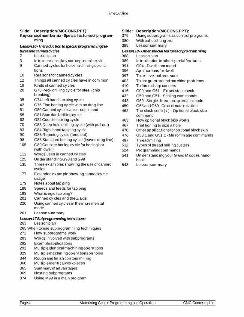
Slide: De scrip tion (MCCON6.PPT):Key con cept num ber six - Spe cial fea tures of pro gram -
ming
Les son 16 - In tro duc tion to spe cial pro gram ming fea -tures and canned cy cles2 Les son plan3 In tro duc tion to key con cept num ber six9 Canned cy cles for hole ma chin ing op er a -
tions10 Rea sons for canned cy cles12 Things all canned cy cles have in com mon19 Kinds of canned cy cles20 G73 Peck drill ing cy cle for steel (chip
break ing)35 G74 Left hand tap ping cy cle42 G76 Fine bor ing cy cle with no drag line51 G80 Canned cy cle can cel com mand55 G81 Stan dard drill ing cy cle62 G82 Coun ter bor ing cy cle70 G83 Deep hole drill ing cy cle (with pull out)83 G84 Right hand tap ping cy cle90 G85 Reaming cy cle (feed out)98 G86 Stan dard bor ing cy cle (leaves drag line)105 G89 Coun ter bor ing cy cle for bor ing bar
(with dwell)112 Words used in canned cy cles125 Un der stand ing G98 and G99135 Three ex am ples show ing the use of canned
cy cles177 Ex tended ex am ple show ing canned cy cle
us age179 Notes about tap ping188 Speeds and feeds for tap ping193 What is rigid tap ping?201 Canned cy cles and the Z axis220 Using canned cy cles in the in cre men tal
mode261 Les son sum mary
Les son 17 Subprogramming tech niques263 Les son plan265 When to use subprogramming tech niques272 How subprograms work283 Words in volved with subprograms292 Ex am ple ap pli ca tions292 Mul ti ple iden ti cal ma chin ing op er a tions329 Mul ti ple ma chin ing op er a tions on holes344 Rough and fin ish con tour mill ing360 Mul ti ple iden ti cal workpieces365 Sum mary of ad van tages369 Nesting subprograms374 Using M99 in a main pro gram
Slide: De scrip tion (MCCON6.PPT):379 Using subprograms as con trol pro grams380 With pal let chang ers385 Les son sum mary
Les son 18 - Other spe cial fea tures of pro gram ming 388 Les son plan389 In tro duc tion to other spe cial fea tures391 G04 - Dwell com mand396 Ap pli ca tions for dwell397 To re lieve tool pres sure403 To pro gram around ma chine prob lems410 To force sharp cor ners416 G09 and G61 - Ex act stop check432 G50 and G51 - Scaling com mands443 G60 - Sin gle di rec tion ap proach mode450 G68 and G69 - Co or di nate ro ta tion462 The slash code ( / ) - Op tional block skip
com mand463 How op tional block skip works467 Trial bor ing to size a hole470 Other ap pli ca tions for op tional block skip476 G50.1 and G51.1 - Mir ror im age com mands497 Thread mill ing512 Types of thread mill ing cut ters524 Pro gramming com mands541 Un der stand ing your G and M codes hand -
book543 Les son sum mary
Time Out line
Page 4 Machining Center Programming and Operation CNC Concepts, Inc.

Slide: De scrip tion (MCCON6.PPT): Sec tion Two: Op er a tionKey con cept num ber seven - Know your ma chine
(MCCON7.PPT)
Les son 19 - The con trol panel 2 Les son plan4 In tro duc tion to op er a tion6 In tro duc tion to key con cept num ber seven7 The op er a tor’s re spon si bil i ties11 The di rec tions of mo tion from an op er a tor’s
view point34 The two most ba sic op er a tion pan els36 The con trol panel36 Ba sic lay out37 Let ter ad dress key pad39 Dis play screen func tions40 Soft key func tions41 Po si tion func tion47 Pro gram func tion50 Off set Func tion52 Pro gram check func tion54 Set ting func tion55 Mes sage func tion56 Hard keys for dis play screen func tions57 Les son sum mary
Les son 20- The ma chine panel 60 Les son plan62 Ma chine panel lay out65 Other but tons and switches you may have74 Other pan els75 Other op er a tor func tions83 Les son sum mary
Key con cept num ber eight - The three modes of ma -chine op er a tion (MCCON8.PPT)
Les son 21The three modes of op er a tion 2 Les son plan3 In tro duc tion to key con cept num ber eight6 The man ual mode11 The man ual data in put mode15 The pro gram op er a tion mode
Slide: De scrip tion (MCCON8.PPT):18 Les son sum maryKey con cept num ber nine - The key se quences of ma -
chin ing cen ter op er a tion (MCCON9.PPT)
Les son 22 - The key se quences2 Les son Plan3 In tro duc tion to key con cept num ber nine8 Un der stand ing the op er a tion hand books9 Man ual se quences11 To start the ma chine16 To do a man ual zero re turn33 To man u ally start the spin dle36 To man u ally jog axes41 To use the handwheel44 Se quence to man u ally load tools into the
spin dle47 Se quence to load tools into the tool changer50 To man u ally turn on and off the cool ant54 To set the axes dis plays61 To en ter and change tool off sets67 To man u ally ac ti vate mir ror im age74 To se lect inch and met ric modes80 Man ual data in put se quences82 To use MDI to change tools89 To use MDI to ac ti vate spin dle95 To use MDI to do a zero re turn99 Pro gram load ing and sav ing and se quence101 To load pro grams by tape107 To load pro grams through the key board111 To send pro grams from the con trol116 Pro gram ed it ing and dis play se quences134 Setup se quences135 To mea sure the pro gram zero point179 To mea sure tool lengths192 Les son sum mary
Key con cept num ber ten - Pro gram ver i fi ca tion(MCCON10.PPT)
Les son 23 - Pro gram ver i fi ca tion pro ce dures 2 Les son plan3 In tro duc tion to key con cept num ber ten5 Safety pri or i ties9 Com mon mis takes14 Pro ce dures to pro gram ver i fi ca tion15 The ma chine lock dry run19 Free flow ing dry run23 Nor mal air cut ting cy cle ex e cu tion27 Run ning the first workpiece31 Run ning ver i fied pro gramsSlide: De scrip tion (MCCON10.PPT):32 Re running tools33 Les son sum mary
Time Out line
CNC Concepts, Inc. Machining Center Programming and Operation Page 5
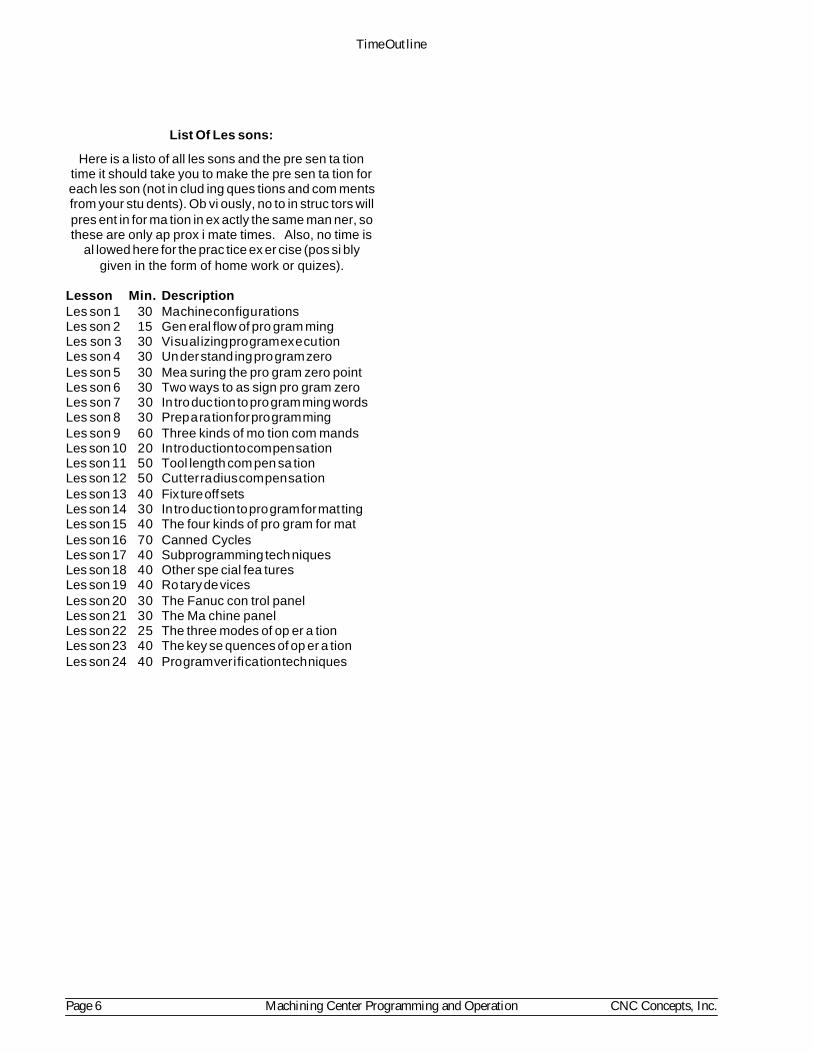
List Of Les sons:
Here is a listo of all les sons and the pre sen ta tiontime it should take you to make the pre sen ta tion foreach les son (not in clud ing ques tions and com mentsfrom your stu dents). Ob vi ously, no to in struc tors willpres ent in for ma tion in ex actly the same man ner, sothese are only ap prox i mate times. Also, no time is
al lowed here for the prac tice ex er cise (pos si blygiven in the form of home work or quizes).
Les son Min. De scrip tionLes son 1 30 Ma chine con fig u ra tionsLes son 2 15 Gen eral flow of pro gram mingLes son 3 30 Vi su al izing pro gram ex e cu tionLes son 4 30 Un der stand ing pro gram zeroLes son 5 30 Mea suring the pro gram zero pointLes son 6 30 Two ways to as sign pro gram zeroLes son 7 30 In tro duc tion to pro gram ming wordsLes son 8 30 Prep a ra tion for pro gram mingLes son 9 60 Three kinds of mo tion com mandsLes son 10 20 In tro duc tion to com pen sa tionLes son 11 50 Tool length com pen sa tionLes son 12 50 Cut ter ra dius com pen sa tionLes son 13 40 Fix ture off setsLes son 14 30 In tro duc tion to pro gram for mat tingLes son 15 40 The four kinds of pro gram for matLes son 16 70 Canned CyclesLes son 17 40 Subprogramming tech niquesLes son 18 40 Other spe cial fea tures Les son 19 40 Ro tary de vicesLes son 20 30 The Fanuc con trol panelLes son 21 30 The Ma chine panelLes son 22 25 The three modes of op er a tionLes son 23 40 The key se quences of op er a tionLes son 24 40 Pro gram ver i fi ca tion tech niques
Time Out line
Page 6 Machining Center Programming and Operation CNC Concepts, Inc.

Pro gramming and Op er ating CNC Routers
Les son Plans
© Copy right 1999, CNC Con cepts, Inc.
NO TICE!!
This man ual is pro tected by copy right laws of theUnited States Gov ern ment. No part of this man ualmay be re pro duced with out the writ ten con sent ofCNC Con cepts, Inc. Ad di tional cop ies of this doc u -ment must be di rectly pur chased from CNC Con -cepts, Inc. (847) 639-8847


Ma chine con fig u ra tions 1Approx. pre sen ta tion time: 20 min utes Ac tiv ities: Lec ture, lab, ex er cise
In tro duc tion to key con cept num ber one:Since this is your very first pre sen ta tion, you’ll want to make your stu dents feel wel come andcom fort able. Ex plain gen eral con sid er ations like course times, break times, and any other pre -lim i nary in for ma tion you wish to re late. Ex plain the key con cepts ap proach and les son struc tureyou’ll be us ing. Ac quaint stu dents with the course ma te ri als (text book and work book), and dis -cuss any other ma te ri als you will be us ing. Point out any ma te ri als you ex pect them to bring toeach class (cal cu la tor, note-taking ma te ri als, etc.). If there are any pre req ui sites stu dents mustun der stand be fore tak ing this course, be sure to men tion them. En cour age par tic i pa tion in theform of ques tions and com ments. Make any other points you wish to make about your learn ingen vi ron ment. It’s also help ful to have stu dents in tro duce them selves. You can get a good ini tialgage of their level by hav ing them talk about their cur rent level of CNC ex pe ri ence - and you mayfind some one who has ex ten sive ex pe ri ence that can help you make your points through out thecourse.
Key con cept num ber one: Know your ma chine from a pro gram mer’s view point. It is, of course, im por -tant that all stu dents get off on the right foot. Be sure to let them know that your us ing a build ingblocks ap proach. If they do not un der stand early pre sen ta tions, they’ll have prob lems later. Have them ques tion any thing they do not un der stand. Use the slide show to in tro duce the seven les sonsre lated to key con cept num ber one. The main thrust of this key con cept is to get be gin ning pro -gram mers un der stand ing the things they must know about CNC rout ers in or der to write CNCpro grams.
Gen eral:Les son one is in tended to help be gin ners un der stand the ba sic machiing prac tice re lated towoodworking as well as the con fig u ra tion of CNC rout ers. While there are a va ri ety of CNCrouter con fig u ra tions, be sure to point out that they share many things in com mon. Through outthis course, you’ll be stress ing the most pop u lar: the bridge style CNC router.
Key points to make:Ba sic ma chin ing prac tice: Though it has lit tle to do with this course cur ric u lum, be sure stu dents un -der stand the im por tance of ba sic ma chin ing prac tice as it re lates to the kind of ma chine t hey willbe pro gram ming. The more they know about ma chin ing prac tice, the eas ier it will be to learnCNC pro gram ming. Since most CNC rout ers are multi-tool ma chines, and since it is not un com -mon for a CNC router pro gram to uti lize many tools, CNC pro gram mers must also know how topro cess workpieces to be ma chined.
Va ri ety of CNC rout ers avail able: While this les son in tro duces a va ri ety of CNC router con fig u ra tions,be sure stu dents un der stand that you will be con cen trat ing most on the bridge style CNC routerfor much of the course. Be sure to point out sim i lar i ties among the var i ous types (among otherthings, axes re main the same from the per spec tive of the spin dle nose, X is al ways left/right, Y isfore/aft, and Z is spin dle in/out). Also ex plain the three most pop u lar ap pli ca tions for bridge styleCNC rout ers (flat board work).
Ma jor com po nents: While CNC pro gram mers do not have to be ma chine de sign ers, it does n’t hurt tofa mil iar ize your stu dents with the most ba sic ma chine com po nents, es pe cially those that are pro -gram ma ble. At the very least, in clude dis cus sions on headstock & spin dle, work hold ing de vices,

ta ble, tool changer, vac uum sys tem and CNC con trol. You may also wish to ex plain the work ings of axis drive sys tems, in clud ing drive mo tors, ball screws, and way sys tems.
Axes of mo tion: Ex plain each axis. If your ma chines have a ro tary axis, be sure to in clude it in yourdis cus sion. Make sure stu dents un der stand the di rec tions of each axis, in clud ing plus and mi nus.
Warn ing about plus ver sus mi nus: Though you may not want to get too bogged down in this pre sen ta -tion if stu dents are hav ing trou ble un der stand ing this point, men tion that there is a dis crep ancy re -gard ing how pro gram mers should view axis mo tion plus and mi nus ver sus the way op er a torsview plus and mi nus. Point out that it is eas i est for pro gram mers if they thing of plus ver sus mi nus as if the tool is ac tu ally mov ing in all axes - and it is in all three axes with bridge style rout ers (toolmov ing to the right is X+, tool mov ing away is Y+, and tool mov ing up is Z+). You must spec ify,how ever, that for some CNC rout ers , it is not the tool that ac tu ally moves to form the axis. In -stead, the ta ble mo tion forms the X and Y axes. Ex plain that fro these ma chines, the ta ble mustmove to the left in or der for the tool to move to ward the right, mean ing ta ble move ment to ward the left
is X plus mo tion. Warn be gin ners that this is a com mon source of con fu sion be tween pro gram mersand op er a tors, since CNC op er a tors tend to look for ta ble mo tion to de ter mine plus/mi nus as op -posed to tool mo tion. Back off if be gin ners are hav ing prob lems un der stand ing this. Ex plain thatyou’ll cover this in more de tail later in this key con cept while dis cuss ing pro gram zero.
Other pro gram ma ble func tions: Let stu dents know that with full blown CNC rout ers, al most any thingthey need to con trol can be con trolled through pro grammed com mands. While you do not want to get bogged down ex plain ing the de tails of how each de vice is pro grammed, at least men tion pro -gram ma ble de vices like spin dle, feedrate, cool ant, au to matic tool changer, pal let changer, andany other pro gram ma ble func tion on your ma chine/s. I like to briefly in tro duce the pro gram mingword/s re lated to each de vice at this point. Also point out that not all ma chine func tions are pro -gram ma ble with some CNC rout ers. The lower the cost, the fewer the num ber of fea tures that will be pro gram ma ble.
How speed and feed are pro grammed: Point out that most CNC rout ers only al low one way to con trolspeed and feedrate. Spin dle speed is pro grammed in RPM (in one-RPM in cre ments) and feedrateis spec i fied in per min ute fash ion (inches or mil li me ters per min ute). This means, of course thatpro gram mers must cal cu late spin dle rpm and inches (or mil li me ters) per min ute feedrate. Theymust, of course, un der stand ba sic ma chin ing prac tice re lated to cut ting con di tions in or der to doso.
Dis cuss the ma chine’s zero re turn po si tion: Ex plain that the zero re turn po si tion (also called grid zero,ma chine zero, or home po si tion) is the ma chine’s ref er ence po si tion. Normally lo cated close tothe plus overtravel limit of each axis, show stu dents this lo ca tion for each of your ma chines.
Other things to do:• Take your stu dents out to see your CNC router/s. Show the com po nents and dem on strate the
di rec tions of mo tion. Es pe cially if ta ble mo tion makes up one or more of the ma chine’s axes,dem on strate plus ver sus mi nus. If you have a pro gram ready to run, show them how a pro gram is run. Keep in mind that the whole idea is to stress the points made so far. Don’t get boggeddown with ques tions on other top ics.
Other notes for this les son:
Les son Plan CNC Router Cur ric u lum
Page 4 CNC Router Programming And Operation CNC Concepts, Inc.

Gen eral flow of the pro gram ming pro cess 2Approx. pre sen ta tion time: 10 min utes Ac tiv ities: Lec ture, ex er cise
Gen eral:This short les son is in tended to help your stu dents get the big pic ture of what goes on in a com -pany’s CNC en vi ron ment. Of course, this course is highly fo cused on pro gram ming and op er a -tion of CNC rout ers. But by giv ing your stu dents the abil ity to step back and see the big gerpic ture, they will better un der stand their role in the CNC en vi ron ment.
Key points to make:Flow of pro gram ming pro cess: Use the slide show and text book to il lus trate what goes on in the CNCen vi ron ment from the de ci sion as to which CNC ma chine will be used for a given op er a tion tostor ing the cor rected ver sion of a ver i fied pro gram once pro duc tion is run ning.
Stress how pro grams can be loaded: While you may elect to have your stu dents typ ing pro grams intothe con trol through the key board for the sake of get ting prac tice, be sure stu dents un der stand thevar i ous meth ods com pa nies use to up load and down load pro grams.
CNC Router Cur ric u lum Les son Plan
CNC Concepts, Inc. CNC Router Programming And Operation Page 5

Other notes for this les son:
Les son Plan CNC Router Cur ric u lum
Page 6 CNC Router Programming And Operation CNC Concepts, Inc.
Vi su al izing the ex e cu tion of a CNC pro gram 3Approx. pre sen ta tion time: 20 min utes Ac tiv ities: Lec ture, lab, ex er cise
Gen eral:At this early stage in the course, be gin ners will still be some what in tim i dated by CNC equip ment. If your dem on stra tion of a CNC CNC router in les son one was a stu dent’s first ex po sure to CNCma chine tools, they will likely think that most of what they have seen is al most magic. In this les -son, you will re move the mys tery from how CNC ma chines func tion, let ting stu dents know thatCNC pro gram ming is highly struc tured and log i cal - not magic.
Key points to make:A pro gram mer must be able to vi su al ize move ments: This point can not be over stressed. With out this abil -ity, the pro gram mer can not write CNC pro grams. Stress that this is why ba sic ma chin ing prac ticeis so very im por tant. But even good wood work ers can some times have trou ble vi su al iz ing. Ex -plain that a per son with good ba sic ma chin ing prac tice ex pe ri ence al ready knows what they wantthe ma chine to do. It will be a rel a tively sim ple mat ter to learn how to tell the ma chine what it is they want it to do. Vi su al izing the tool’s move ments dur ing the cut ting of a workpiece is of par a mountim por tance when it co mes to tell ing the ma chine what it is you want it to do.
Give an anal ogy to travel in struc tions: In the slide show we em pha size this need for vi su al iza tion bygiv ing a sim ple anal ogy. Be fore a per son can write down a set of travel in struc tions, they mustfirst be able to vi su al ize the path from the start point to the end point. Only then can a set ofstep-by-step in struc tions be writ ten. In sim i lar fash ion, a CNC pro gram mer must be able to vi su -al ize the step-by-step man ner that a workpiece is ma chined be fore a CNC pro gram can be writ ten.
Com pare a CNC pro gram’s ex e cu tion to run ning a man ual ma chine: We give an ex am ple dur ing the slideshow and in the book for drill ing a hole on a drill press. Use this ex am ple to stress how to vi su al -ize a pro gram’s mo tions. Any ex pe ri enced ma chin ist could eas ily list the step by step pro ce dures(es pe cially if stand ing right in front of the ma chine) needed to drill a hole on a drill press (turnspin dle on, po si tion tool, turn on cool ant, plunge hole, re tract, etc.). How ever, when sit ting be -hind a desk, armed with lit tle more than print, pa per, pen cil, and cal cu la tor, vi su al iz ing these steps is not so easy. But this kind of vi su al iza tion is man da tory in or der to write CNC pro grams.
Ex plain the make-up of a CNC pro gram: The slide show and text book of fer very good ex am ples of aCNC pro gram’s struc ture. Stress how pro grams are made up of com mands (or blocks). Com parethe com mands of a CNC pro gram to the sen tences in the Eng lish lan guage. Ex plain that, like s en -tences, CNC com mands are made up of words. Point out that each CNC word is made up of a let ter
ad dress and a nu mer i cal value. Make sure stu dents un der stand that just as sen tences in the set oftravel in struc tions tell a per son how to get from point A to point B, CNC com mands tell the CNCma chine how to ma chine a workpiece.
Ex plain the se quen tial or der of CNC pro gram ex e cu tion: Point out that the CNC con trol will ex e cute aCNC pro gram in ex actly the same man ner a per son will fol low a set of travel in struc tions - se quen -
tially. With the travel in struc tions, first the per son will read and in ter pret the first in struc tion anddo what it tells them. Only then will they pro ceed to the next in struc tion. In sim i lar fash ion, theCNC con trol will read, in ter pret, and ex e cute the first com mand in the CNC pro gram. Only thenwill it move on to the next com mand. (Actually, just as the per son fol low ing travel in struc tions, itwill start in ter pret ing the next com mand as it ex e cutes the cur rent com mand.) Point out that justas a per son will fol low the set of travel in struc tions to the let ter, so will a CNC con trol ex e cute apro gram ex actly as it is writ ten. Just as a bad in struc tion in the set of travel in struc tions re sults in aper son get ting lost, in cor rect com mands in the CNC pro gram re sults in in cor rect mo tions.
CNC Router Cur ric u lum Les son Plan
CNC Concepts, Inc. CNC Router Programming And Operation Page 7

There is only one re sult per CNC com mand: Ex plain that the Eng lish sen tences given in the set of travelin struc tions are sub ject to mis in ter pre ta tion. Mis in ter pre ta tions lead to sev eral po ten tial re sultsto a given in struc tion. Ex plain that this is not the case with the ex e cu tion of a CNC pro gram. Re -gard less of the or der of CNC words within a CNC com mand, the con trol will only have one re sul -tant in ter pre ta tion of what will be done. In this sense, CNC pro grams are rig idly struc tured.
Other things to do:• Since this les son in cludes a com plete CNC pro gram (in the vi su al iza tion anal ogy), you may
want to pause long enough to dis cuss some of the ac tual words in volved in pro gram ming. Though you must point out that you don’t ex pect stu dents to re mem ber all of what you’re say -ing (yet), it’s good to ex pose them to CNC pro gram ming words in the con text of a CNC pro -gram as early in the course as pos si ble.
• At the very least, ex plain dec i mal point pro gram ming and the mean ings of words like modaland in i tial ized. Show why dec i mal points are so im por tant within cer tain CNC words byshow ing the older fixed for mat and how the con trol will in ter pret X, Y, and Z co or di nates i f the dec i mal point is not in cluded in the word.
• To stress the se quen tial or der of CNC pro gram ex e cu tion, dem on strate the run ning of a CNCpro gram on your own ma chine while the ma chine is un der the in flu ence of sin gle block. Getthe pro gram up on the dis play screen and ex e cute it line by line, show ing your stu dents how t he pro gram is ex e cuted step-by-step.
Other notes for this les son:
Les son Plan CNC Router Cur ric u lum
Page 8 CNC Router Programming And Operation CNC Concepts, Inc.

Un der stand ing pro gram zero 4Approx. pre sen ta tion time: 20 min utes Ac tiv ities: Lec ture, ex er cise
Gen eral:This les son is the first of three that deals with pro gram zero. Stu dents must un der stand how po si -tion ing move ments are com manded for CNC ma chine tools. While ex pe ri enced CNC peo pletake this for granted, be gin ners may find this con cept a lit tle dif fi cult to com pre hend. Be gin byask ing this ques tion: “How many rev o lu tions of an axis drive mo tor or ball screw does it take to cause one inch
of lin ear mo tion?” Of course no one will be able to an swer, but this should get them think ing abouthow mo tion is gen er ated. Ex plain that while very early NC ma chines (over 30 years ago) re -quired this kind of cryp tic pro gram ming, thanks to a fea ture called pro gram zero we no lon ger haveto be con cerned about the in ter nal work ings of the ma chine to cause pre cise axis mo tion. It’s han -dled on a much higher level.
Key points to make:Give the graph anal ogy: In the slide show and text book we show an ex cel lent anal ogy that shouldhelp you eas ily ex plain pro gram zero. Ev ery one has had to cre ate or in ter pret a graph. Use thisprior knowl edge to ex plain the ba sics of what pro gram zero is all about. Dis cuss that like thebase lines of the graph, CNC ma chines have lin ear axes. Just as the base lines of a graph rep re sentsome thing (time and pro duc tiv ity in our ex am ple), so do the axes of a CNC ma chine rep re sent anac tual point in space. Just as base lines are bro ken into in cre ments, so are axes bro ken into lin earmea sure ment in cre ments (in inches or mil li me ters). And most im por tantly, point out that j ust as a graph will have an or i gin (where the base lines cross), so will each axis have a pro gram zero point. Make sure stu dents un der stand that pro gram zero is the or i gin for po si tions to be in cluded withinthe CNC pro gram. In stead of hav ing to spec ify the num ber of rev o lu tions of a drive mo tor or ballscrew, the CNC pro gram mer will spec ify move ments by des ig nat ing po si tions rel a tive to pro -gram zero. And in stead of plot ting points that rep re sent con cep tual ideas, CNC pro gram mers will be plot ting phys i cal lo ca tions in space for tool move ments.
Dis cuss the small est in cre ment for pro gram ming: As stated, each axis is bro ken into mea sure ment in cre -ments. Point out that the in put mode (inch or met ric) de ter mines how small the in cre ments willbe. In the inch mode, the small est in cre ment is 0.0001 in for most CNC rout ers. Point out that thismeans a ten inch long lin ear axis has 100,000 po si tions!
Dis cuss plus and mi nus: Point out that in the graph anal ogy, it just so hap pened that all points fell upand to the right of the or i gin. Be sure your stu dents know that this is but one quad rant in the co or -di nate sys tem. Points plot ted in this area are plus in both axes. How ever, with CNC pro gram -ming, it is likely that points must be plot ted in other quad rants. Use the draw ings in the text bookand slide show to il lus trate how to de ter mine the po lar ity of points plot ted in other quad rants.
Warn be gin ners about for get ting the point of or i gin for po lar ity: It is not un com mon for be gin ners to haveprob lems un der stand ing how to de ter mine a point’s po lar ity. Be sure stu dents un der stand that the pro gram zero point is the point of or i gin for all move ments, and the sign of the co or di nate is de ter -mined ac cord ingly. To elab o rate, dem on strate times when a pos i tive move ment must be made toget to a neg a tive po si tion (the start ing point of the mo tion is yet more neg a tive than the end ingpoint).
Where to place the pro gram zero point: Be sure be gin ners un der stand that the place ment of pro gramzero is very flex i ble, and com monly this place ment is at the dis cre tion of the pro gram mer. Usethe slide show and man ual to dem on strate that the dimensioning tech niques on the workpiecedraw ing de ter mine where pro gram zero is placed. The or i gin of each axis (da tum sur face) on the
CNC Router Cur ric u lum Les son Plan
CNC Concepts, Inc. CNC Router Programming And Operation Page 9

print makes an ex cel lent pro gram zero point. Ex plain that the wise place ment of pro gram zero re -sults in many of the co or di nates go ing into the pro gram com ing right from the draw ing. Alsopoint out that some de sign en gi neers do not di men sion in a log i cal man ner. If hav ing trou ble de -ter min ing the best pro gram zero lo ca tion, have be gin ners ask them selves from which sur faces theworkpiece will be lo cated in the setup. Lo ca tion sur faces make an ex cel lent pro gram zero point.
Ex plain ab so lute ver sus in cre men tal pro gram ming: Stress that when ever us ing pro gram zero as the pointof or i gin for caus ing move ments, the pro gram mer is work ing in the ab so lute mode. Be sure be -gin ners un der stand that this is the best mode for pro gram ming and that a G90 com mand is used on most CNC rout ers to des ig nate ab so lute po si tion ing move ments. How ever, be gin ners shouldalso un der stand that move ments can be made incrementally (by des ig nat ing G91). Ex plain thatthe tool’s cur rent po si tion is the point of or i gin when work ing in the in cre men tal mode. Use theslide show and man ual to dem on strate the dif fer ences.
Dis cuss the ad van tages of the ab so lute mode: Use the slide show and text book to de scribe why be gin ners should con cen trate on ex clu sively us ing the ab so lute mode (co or di nates are eas ier to cal cu late,co or di nates make sense, mis takes are not com pounded, etc.). While you may want to men tion ap -pli ca tions for in cre men tal pro gram ming (most hav ing to do with subprogramming tech niques),urge be gin ners to work ex clu sively in the ab so lute mode un til they are very com fort able with pro -gram ming.
Warn be gin ners about think ing incrementally: Warn your stu dents that be gin ners have the ten dency tothink incrementally. When pro gram ming move ments, they tend to ask them selves how farshould the tool move. Get them to ask to what po si tion should the tool move. In the ab so lute move,this po si tion is al ways rel a tive to pro gram zero.
Other things to do:• Have stu dents prac tice de ter min ing the best lo ca tion for pro gram zero based on a va ri ety of
prints.
• Have stu dents prac tice de ter min ing the co or di nates for points needed within CNC pro gramswith a se ries of prac tice prints.
As they catch on:• When it co mes to the small est in cre ment for pro gram ming, you stressed that in the inch mode,
the small est in cre ment is 0.0001 inch. While most com pa nies in the US still work in the inchmode, you may want to make stu dents aware that in the met ric mode, the small est in cre ment is0.001 mil li me ters. 0.001 mm is ac tu ally less than half of 0.0001 inch, mean ing the ma chinehas a finer res o lu tion in the met ric mode. In fact, the same ten inch long lin ear axis that has100,000 po si tions in the inch mode has 254,000 po si tions in the met ric mode! Ex plain that this gives the CNC user the abil ity to hold tighter tol er ances in the met ric mode, since po si tions can be pro grammed to a finer res o lu tion and off sets can be mod i fied in smaller in cre ments.
Other notes for this les son:
Les son Plan CNC Router Cur ric u lum
Page 10 CNC Router Programming And Operation CNC Concepts, Inc.

Mea suring the pro gram zero lo ca tion 5Approx. pre sen ta tion time: 20 min utes Ac tiv ities: Lec ture, lab, ex er cise
Gen eral:Stu dents must un der stand that just be cause they wish the pro gram zero point to be in a given lo ca -tion, the con trol will not au to mat i cally know the po si tion of this lo ca tion. By one means or an -other, pro gram zero must be as signed. Ex plain that this as sign ment mar ries the CNC pro gram tothe setup in the CNC router, and in es sence, cal i brates the ma chine with the tools held in the spin -dle. While there are many ways to ac tu ally as sign pro gram zero, and while some are much moreef fi cient that those we show, our given meth ods are based on ease-of-understanding, and be gin -ners should readily catch on to what the pro gram zero as sign ment rep re sents. Do point out thatthe meth ods shown can be im proved upon as they catchon.
Key points to make:Un der stand ing the zero re turn po si tion: Use the slide show to il lus trate that the ma chine’s zero re turnpo si tion is the ref er ence point of the pro gram zero as sign ment val ues. That is, the mea sure mentsare taken be tween pro gram zero to the spin dle while the ma chine is rest ing at the zero re turn po si -tion.
The pro gram zero set ting val ues: While there are some ex cep tions, use the slide show and text book toex plain that many CNC rout ers re quire that the dis tance be tween pro gram zero and the spin dle (cen ter in
X/Y, nose in Z) be de ter mined in or der to as sign pro gram zero. One value is re quired for each axis,and we’ll call these val ues the pro gram zero set ting val ues.
One way to de ter mine the pro gram zero set ting val ues is to mea sure them: Use the slide show and text book toshow one method of mea sur ing the pro gram zero as sign ing val ues. Be sure stu dents un der standthat this is a rather crude way of do ing it, but it makes it easy to vi su al ize what the pro gram zero as -sign ing num bers rep re sent. In re al ity, there are spe cial tech niques and ma chine func tions that can be used to stream line - if not elim i nate- these mea sure ments. Point out that dur ing these mea sure -ments, the ma chine is sim ply be ing used as a mea sur ing de vice.
What about vari a tions in tool length: As stated, the pro gram zero as sign ing val ues are spec i fied to thecen ter of the spin dle in X/Y. How ever, ex plain that in the Z axis there are ac tu ally two pop u larways to de ter mine the pro gram zero as sign ment value, based on how tool length com pen sa tion isused. Though tool length com pen sa tion is dis cussed un til key con cept num ber four, ex plain howthe Z axis pro gram zero as sign ing value is de ter mined now based upon how you in tend to teachtool length com pen sa tion. If you use our rec om mend method of teach ing tool length com pen sa -tion, each tool’s length will be stored in a tool length com pen sa tion off set. In this case, the Z axispro gram zero as sign ing value will be the dis tance be tween pro gram zero and the spin dle nosewhile the ma chine is rest ing at its zero re turn po si tion. If you teach the sec ond ary method of us ing tool length com pen sa tion (dis tance from each tool tip down to pro gram zero is off set), the Z axispro gram zero as sign ment value will be zero.
The pro gram zero point as sign ment sim ply tar gets the tool ing: Be sure stu dents un der stand that even ifmea sure ments are made very cau tiously, it is likely that dis crep an cies in the static mea sure mentsthey make from the ac tual dy nam ics of cut ting a workpiece will cause mi nor vari a tions in the firstworkpiece be ing ma chined. That is, just be cause the pro gram zero point is cor rectly mea sured isno guar anty that each tool will cut per fectly. Ad di tionally, other prob lems caused by tool wearwill mean more vari a tions in workpiece size dur ing the pro duc tion run. Point out that these prob -lems are han dled by other means (tool length com pen sa tion, cut ter ra dius com pen sa tion, and trial
CNC Router Cur ric u lum Les son Plan
CNC Concepts, Inc. CNC Router Programming And Operation Page 11

ma chin ing), and that while pro gram zero as sign ing num bers should be as ac cu rate as pos si b le,they are re ally only tar get ing the po si tion of pro gram zero.
Other things to do:• While this is han dled in much greater de tail dur ing the op er a tion sec tion of the course, it
would n’t hurt to go out to the ma chine and dem on strate the ac tual tech niques used to mea surethe pro gram zero as sign ing val ues for a sim ple setup.
As they catch on:• Dur ing re views of this ma te rial, push what stu dents al ready know about pro gram zero as sign -
ing val ues a lit tle fur ther. Ask if they can come up with any sug ges tions for min i miz ing t henum ber of mea sure ments that must be made to de ter mine pro gram zero as sign ing val ues. Ex -am ples in clude:
No need to remeasure the pro gram zero point the next time the setup is made if the setup isqual i fied (lo cat ing fix ture/vise from the ma chine’s ta ble slots).
By know ing some con stant val ues, it will be pos si ble to cal cu late the pro gram zero as sign -ing val ues, elim i nat ing mea sure ments al to gether for qual i fied set ups.
Other notes for this les son:
Les son Plan CNC Router Cur ric u lum
Page 12 CNC Router Programming And Operation CNC Concepts, Inc.

Pro gramming and Op er atingCNC Routers
and woodworking ma chin ing cen ters
© Copy right 1999, CNC Con cepts, Inc.
Pub lished By:
NO TICE!!
This man ual is pro tected by copy right laws of the UnitedStates Gov ern ment. No part of this man ual may be re pro -duced with out the writ ten con sent of CNC Con cepts, Inc.Ad di tional cop ies of this doc u ment must be pur chased di -rectly from CNC Con cepts, Inc. (847) 639-8847Written by Mike Lynch
Doc u ment num ber: S00041


Ta ble of Con tents
Part One - Pro gramming
Key con cept num ber one - Know your ma chine, 1-1Les son 1
Ba sic ma chin ing prac tice re lated to CNC rout ers and woodworking ma chin ing cen ters, 1-1Hole ma chin ing op er a tions, 1-2
Spot drill ing, 1-2Twist drills, 1-3Coun ter sink ing, 1-4Coun ter bor ing tools, 1-5
Routing, 1-6Cut ting con di tions for rout ing, 1-6Types of router bits, 1-7
Ma chine con fig u ra tions, 1-9CNC rout ers ver sus CNC woodworking ma chin ing cen ters, 1-9
Ba sic com po nents, 1-9Other pro gram ma ble fea ture of CNC rout ers and ma chin ing cen ters, 1-11
Tool chang ing, 1-11Spin dle speed, 1-11Spin dle di rec tion, 1-11Feedrate, 1-11What else might be pro gram ma ble?, 1-11
Les son 2Gen eral flow of the pro gram ming pro cess, 1-12
De ci sion is made as to which CNC ma chine to use, 1-12The ma chin ing pro cess is de vel oped, 1-12Tooling is or dered and checked, 1-12The pro gram is de vel oped, 1-12Setup doc u men ta tion is made, 1-12Pro gram is loaded into the CNC con trol’s mem ory, 1-12The set up is made, 1-13The pro gram is cau tiously ver i fied, 1-13Pro duc tion is run, 1-13Cor rected ver sion of the pro gram is stored for fu ture use, 1-13
Les son 3Vi su al izing the ex e cu tion of a CNC pro gram, 1-15
Pro gram make-up, 1-15Method of pro gram ex e cu tion, 1-16A note about dec i mal point pro gram ming, 1-17Other mis takes of omis sion, 1-18Modal words, 1-18Ini tial ized words, 1-18Word or der in a com mand, 1-18
Les son 4Un der stand ing pro gram zero and the rect an gu lar co or di nate sys tem, 1-19
What about Z?, 1-20
Spe cial Fea tures Of Programming
CNC Concepts, Inc. Programming and Operating CNC Routers Page one

Un der stand ing plus and mi nus, 1-21Pro gram zero, 1,22Where to place your pro gram zero point, 1-22
What about Z?, 1-25Ex am ple show ing how co or di nates are cal cu lated, 1-25
Ab so lute vs in cre men tal, 1-26Warn ing about think ing incrementally, 1-27
Be sure to use the dec i mal point when spec i fy ing axis po si tions, 1-27Les son 5
Lo cating the pro gram zero point for a pro gram, 1-29What is the zero re turn po si tion?, 1-29
How to mea sure the pro gram zero point lo ca tion on the ma chine, 1-29Mea suring the X and Y axis pro gram zero as sign ment val ues:, 1-31To mea sure the pro gram zero as sign ment value in Z:, 1-32Do you have to phys i cally mea sure the pro gram zero point?, 1-33
Les son 6The two ways to as sign pro gram zero, 1-34
Ad van tages of as sign ing pro gram zero with fix ture off sets, 1-34Safety, 1-34Ease of use, 1-34Ef fi ciency, 1-34Re running tools, 1-34
As signing pro gram zero with fix ture off sets (G54-G59), 1-35As signing pro gram zero in the pro gram, 1-35
Les son 7In tro duc tion to pro gram ming words, 1-37
Note About Dec i mal Points, 1-37G and M words, 1-41
G words, 1-41Note on Op tion G Codes, 1-41
A re minder about in i tial ized G codes, 1-41Typ i cal M codes for a CNC router or ma chin ing cen ter, 1-43
Why Learn Man ual Pro gramming?, 1-44Con clu sion to key con cept num ber one, 1-44
Key con cept num ber two - Prep a ra tion for pro gram ming, 2-1Les son 8
The im por tance of prep a ra tion, 2-1Prep a ra tion and safety, 2-2Typ i cal mis takes, 2-3
Syn tax mis takes, 2-3Mo tion mis takes, 2-3Mis takes of omis sion, 2-3Pro cess mis takes, 2-4
Steps for pre par ing to write a CNC pro gram, 2-5Mark ing up the print, 2-5
Pre pare the ma chin ing pro cess, 2-5De velop the needed cut ting con di tions, 2-8
Page two Programming and Operating CNC Routers CNC Concepts, Inc.

Do the re quired math , 2-8Check the re quired tool ing, 2-10
Plan the work hold ing set-up, 2-11Other doc u men ta tion, 2-11
Set-up sheet, 2-11Pro gram list ing, 2-11
Is it all worth it?, 2-13
Key con cept num ber three - Types of mo tion com mands, 3-1Les son 9
Types of mo tion com mands, 3-1What is in ter po la tion?, 3-1Mo tion com mon al ties, 3-2Un der stand ing the pro grammed point of each cut ting tool, 3-3
G00 Rapid mo tion (also called po si tion ing), 3-4When do you rapid?, 3-5
What is a safe ap proach dis tance?, 3-5G01 lin ear in ter po la tion (straight line mo tion), 3-7
Using G01 for fast ap proach, 3-8Ma chine holes with G01?, 3-8
G02 and G03 Cir cu lar mo tion com mands, 3-9Which po si tions to pro gram, 3-9Spec ifying arc size with the R word, 3-9More de tails of clock wise ver sus coun ter clock wise, 3-11Cir cu lar mo tion with di rec tional vec tors (I, J, and K), 3-11Arc lim i ta tions, 3-12Full cir cle in one com mand, 3-14
Key con cept num ber four -The three kinds of com pen sa tion, 4-1Les son 10
What is com pen sa tion?, 4-1Un der stand ing off sets, 4-2
How many off sets do you have?, 4-2Off sets and trial cut ting, 4-2Or ga ni za tion of off sets, 4-3Wear off sets ver sus ge om e try off sets, 4-5How off sets are in stated, 4-5
Les son num ber 11Tool length com pen sa tion, 4-6
The rea son for tool length com pen sa tion, 4-6What About in ter fer ence and reach?, 4-7Tool off sets used with tool length com pen sa tion, 4-7How tool length com pen sa tion is used, 4-8Using the tool length as the off set (rec om mended method), 4-8
Mea suring the tool length in the ma chine, 4-9Mea suring tool lengths off-line, 4-10
Putting it all to gether - An ex am ple pro gram show ing tool length com pen sa tion, 4-12Fi nal notes about us ing the tool length as the tool length com pen sa tion off set, 4-14
CNC Concepts, Inc. Programming and Operating CNC Routers Page three

Using the dis tance from the tip of the tool down to pro gram zero in Z as the off set value, 4-14Mea suring the dis tance from the tip of the tool to pro gram zero, 4-15Ex am ple pro gram show ing large neg a tive value as off set, 4-16Fi nal notes about us ing the dis tance from the tip of the tool down as the off set, 4-17
Sizing with tool length com pen sa tion, 4-18Trial cut ting with tool length com pen sa tion, 4-19Con clu sion to tool length com pen sa tion, 4-19
Les son 12Router ra dius com pen sa tion, 4-21
Rea sons for us ing router ra dius com pen sa tion, 4-21Making cal cu la tions eas ier for man ual pro gram mers, 4-21Range of router bit sizes, 4-23Sizing the workpiece, 4-23Roughing and fin ish ing, 4-23
How router ra dius com pen sa tion works, 4-24How to pro gram router ra dius com pen sa tion, 4-25
What about router bits with mul ti ple di am e ters?, 4-25Steps to pro gram ming router ra dius com pen sa tion, 4-26
In stating router ra dius com pen sa tion, 4-26Making move ments un der the in flu ence of router ra dius com pen sa tion, 4-29Can celing router ra dius com pen sa tion, 4-29
Other notes about router ra dius com pen sa tion, 4-30Ex am ple pro grams show ing router ra dius com pen sa tion, 4-30
Cut ting one end of a workpiece, 4-30Ex am ple show ing the rout ing of an out side con tour, 4-32Ex am ple show ing cut ting of in side cir cle with arc-in/arc-out, 4-34
Using router ra dius com pen sa tion with the off set re flect ing the de vi a tion from the planned routerbit size, 4-36
Sizing with router ra dius com pen sa tion, 4-36Trial cut ting with router ra dius com pen sa tion, 4-37
Les son 13Fix ture off sets, 4-38
When are mul ti ple pro gram zero points re quired?, 4-38The two ways to as sign fix ture off sets for mul ti ple pro gram zero points, 4-39
Using the com mon off set, 4-39Pro gramming off set changes with G10, 4-41Other uses for the com mon fix ture off set, 4-42
Al lowing for axis vari a tions af ter a mis hap, 4-42Dif fer ences in spin dle gap from one ma chine to an other, 4-42To en hance safety dur ing dry runs, 4-42
Pro gramming with fix ture off sets, 4-42Spe cial note about fix ture off sets and tool length com pen sa tion, 4-44
Key con cept num ber five - Pro gram For matting, 5-1Les son 14
Pro gram for mat ting, 5-1Rea sons for pro gram for mat ting, 5-1
Fa mil iar iza tion, 5-1
Page four Programming and Operating CNC Routers CNC Concepts, Inc.

Con sis tency, 5-2Re-running tools, 5-2
The four for mat sets, 5-3For mat pri or i ties, 5-3
One ac tiv ity per com mand, 5-3Ap proach mo tions, 5-3Rapid ap proach dis tance, 5-3
M code dif fer ences, 5-3Vari a tions in au to matic tool chang ing de vices, 5-4
Sin gle arm, 5-4Dou ble arm, 5-4Tur ret type, 5-5What if you don’t have an au to matic tool changer?, 5-5
When do you change tools?, 5-5Do you have other ac ces so ries?, 5-5How to use the for mats, 5-6
Les son 15The four kinds of pro gram for mat, 5-7
A note about in i tial ized states, 5-7For mat for CNC ma chin ing cen ters us ing fix ture off sets, 5-8
Ex am ple pro gram for a CNC ma chin ing cen ter us ing fix ture off sets to as sign pro gram zero,5-11
For mat for CNC ma chin ing cen ters us ing G92 to as sign pro gram zero, 5-13N001-N003, 5-14Ex am ple pro gram for ma chin ing cen ters us ing G92 to as sign pro gram zero, 5-16
For mat for CNC rout ers us ing fix ture off sets, 5-18Ex am ple pro gram for a CNC router us ing fix ture off sets to as sign pro gram zero, 5-21
For mat for CNC rout ers us ing G92 to as sign pro gram zero, 5-23N001-N003, 5-23Ex am ple pro gram for CNC rout ers us ing G92 to as sign pro gram zero, 5-26
Con clu sion to Pro gram For matting, 5-28
Key con cept num ber six - Spe cial fea tures of pro gram ming, 6-1Les son 16
In tro duc tion to spe cial pro gram ming fea tures, 6-1Canned cy cles for hole ma chin ing op er a tions, 6-2
De scrip tion of each canned cy cle, 6-3G73 Peck drill ing cy cle for steel (chip break ing), 6-3G74 Left hand tap ping cy cle, 6-3G80 Canned cy cle can cel com mand, 6-4G81 Stan dard drill ing cy cle, 6-4G82 Coun ter bor ing cy cle, 6-4G83 Deep hole drill ing cy cle (with pull out), 6-4G84 Right hand tap ping cy cle, 6-5G85 Reaming cy cle (feed out), 6-5G86 Boringcycle, 6-5
Words used in canned cy cles, 6-6Un der stand ing G98 and G99, 6-6
CNC Concepts, Inc. Programming and Operating CNC Routers Page five

Ex tended ex am ple show ing canned cy cle us age, 6-7Canned cy cles and the Z axis, 6-10Using canned cy cles in the in cre men tal mode, 6-11Con clu sion to canned cy cles, 6-14
Les son 17Subprogramming tech niques, 6-15
Ap pli ca tions for subprogramming, 6-15Re peated ma chin ing op er a tions, 6-15Con trol pro grams, 6-16Util ity ap pli ca tions, 6-16
Words re lated to subprograms, 6-16Ex am ples for re peat ing ma chin ing op er a tions, 6-17Con trol pro gram ex am ple, 6-24A util ity ex am ple, 6-24
Un der stand ing G10, 6-25Other notes about subprogramming, 6-26
Nesting subprograms, 6-26Mul ti ple ex e cu tions, 6-26
What is para met ric pro gram ming?, 6-28Part fam i lies, 6-28User de fined canned cy cles, 6-28Util ities, 6-28Com plex mo tions and shapes, 6-28Driving op tional de vices (like probes), 6-28
Les son 18Other spe cial fea tures of pro gram ming, 6-29
Op tional block skip (also called block de lete), 6-29Ap pli ca tions for op tional block skip, 6-29Warn ing about op tional block skip ap pli ca tions, 6-30
Se quence num ber (N word) tech niques), 6-31G04 - Dwell com mand, 6-32G09 and G61 - Ex act stop check, 6-32G10 - Off set set ting by pro grammed com mand, 6-33
Ap pli ca tions for G10, 6-34Plane se lec tion com mands (G17, G18, and G19), 6-35Inch/met ric mode se lec tion G20, G21, 6-35Sec ond ary ref er ence po si tion, G30, 6-36Scaling com mands, G50 & G51, 6-36G50.1 and G51.1 - Mir ror im age com mands, 6-36
Gen eral ex pla na tion of mir ror im age, 6-36Ap pli ca tions for mir ror im age, 6-37The two ways to ac ti vate mir ror im age, 6-37
Tem po rary shift of pro gram zero point, G52, 6-38Mo tion rel a tive to zero re turn po si tion, G53, 6-38Im por tant M codes, 6-38Con clu sion to spe cial fea tures of pro gram ming, 6-39
Page six Programming and Operating CNC Routers CNC Concepts, Inc.

Part Two - Setup and Op er a tion
Key con cept num ber seven - Know your ma chine and your du ties, 7-1Les son 19
Tasks re lated to setup and op er a tion, 7-1Setup tasks ver sus pro duc tion main tain ing tasks, 7-1Tasks re lated to setup, 7-2
Tear down pre vi ous setup, 7-2Make work hold ing setup, 7-2As sign pro gram zero/s, 7-2As sem ble cut ting tools, 7-5Mea sure tool length com pen sa tion val ues, 7-6Mea sure router ra dius com pen sa tion val ues, 7-7En ter off sets re lated to cut ting tools, 7-8Load tools into the ma chine’s au to matic tool changer mag a zine, 7-9Load the CNC pro gram/s into the con trol, 7-9Ver ify the cor rect ness of the CNC pro gram, 7-10Cau tiously ma chine first workpiece, 7-10Pro gram op ti miz ing, 7-11First workpiece in spec tion, 7-11Saving cor rected ver sion of the pro gram, 7-11What will you be do ing?, 7-11
Tasks re lated to main tain ing pro duc tion, 7-11Workpiece un load and load, 7-11Main taining crit i cal di men sions (with close tol er ances) dur ing each tool’s life, 7-12Re placing worn tools , 7-12Other pos si ble tasks to be done dur ing the pro duc tion run, 7-13
A sam ple of setup and pro duc tion run doc u men ta tion, 7-14Ru di men tary tools to ac com plish op er a tion tasks, 7-15
Man ual axis mo tion, 7-15Man ual con trol of the au to matic tool changer, 7-16Man ual spin dle con trol, 7-16Con trol of po si tion dis plays (dig i tal read outs), 7-16Pro gram trans fers, 7-17Mas tery of ac ces sory de vices, 7-17
Ma chine com po nents and di rec tions of mo tion from an op er a tors point of view, 7-17Les son 20
The two op er a tion pan els, 7-18The con trol panel, 7-19
Power but tons, 7-19Dis play screen con trol keys, 7-19Let ter Keys, 7-21The shift key, 7-21The slash key (/), 7-21Num ber keys, 7-21Dec i mal point key, 7-21Arith me tic op er a tor keys, 7-22The in put key, 7-22
CNC Concepts, Inc. Programming and Operating CNC Routers Page seven

Cur sor con trol keys, 7-22Pro gram Editing Keys, 7-22Re set but ton, 7-23Other keys on the con trol panel, 7-23
The ma chine panel, 7-24Mode switch, 7-24Cy cle start, 7-25Feed hold, 7-25Feedrate over ride, 7-26Rapid tra verse over ride, 7-26Emer gency stop, 7-27Con di tional switches, 7-27Man ual con trols, 7-28In di ca tor lights and me ters, 7-30Other but tons and switches on the ma chine panel, 7-30
Other pos si ble op er a tion pan els, 7-30
Key con cept num ber eight - The three modes of ma chine op er a tion, 8-1Les son 21
Three modes of op er a tion, 8-1The man ual mode, 8-1The man ual data in put mode, 8-1
The man ual data in put po si tion of the mode switch, 8-2The edit po si tion of the mode switch, 8-3
The pro gram op er a tion mode, 8-4The mem ory (or auto) mode switch po si tion, 8-4The tape mode switch po si tion, 8-5
Key con cept num ber nine - The key op er a tion pro ce dures, 9-1Les son 22
Key se quences, 9-1Op er a tion hand books, 9-1
The most im por tant pro ce dures, 9-1
Key con cept num ber ten - Un der stand how to safely ver ify pro grams, 10-1Les son 23, 10-1
Pro gram ver i fi ca tion tech niques, 10-1Safety pri or i ties, 10-1
Op er a tor safety, 10-1Ma chine tool safety, 10-1Workpiece safety, 10-2
Typ i cal mis takes, 10-2Syn tax mis takes in the pro gram, 10-2Mo tion mis takes in the pro gram, 10-3Set-up mis takes, 10-3Mis takes of omis sion, 10-3
Pro ce dures to pro gram ver i fi ca tion, 10-3The ma chine lock dry run, 10-4
Page eight Programming and Operating CNC Routers CNC Concepts, Inc.

Free flow ing dry run, 10-4Nor mal air cut ting cy cle ex e cu tion, 10-5Run ning the first workpiece, 10-5
Making good parts, 10-6Run ning pro duc tion and op ti miz ing, 10-6
Con clu sion to Pro gram Ver i fi ca tion, 10-6
CNC Concepts, Inc. Programming and Operating CNC Routers Page nine

Page ten Programming and Operating CNC Routers CNC Concepts, Inc.

Course De scrip tion and Ori en ta tion
It is the in ten tion of this course to in tro duce be gin ners and ex pe ri enced pro gram mers alike to pro gram -ming, setup, and op er a tion tech niques used with CNC rout ers and woodworking ma chin ing cen ters. Wewill be gin in a ba sic man ner, en sur ing that even new com ers to CNC will be able to fol low all pre sen ta -tions. As the course pro gresses, we will con stantly build upon pre vi ously pre sented in for ma tion, mak ingit easy (even for the com plete nov ice to CNC) to fol low along with the course with a min i mum of ef fort.This build ing blocks ap proach will be used for the en tire course, and when fin ished, you will have a thor -ough un der stand ing of what pro gram ming, setup, and op er a tion are all about.
Key con cepts ap proach
Our key con cepts ap proach will keep a light at the end of the tun nel, let ting you know where you stand asyou prog ress. They will also help you keep your thoughts or ga nized, giv ing you a proven way to learnabout CNC.
There are ten key con cepts you must mas ter to be come pro fi cient. Key con cepts one through six are re -lated to pro gram ming, while key con cepts seven through ten are re lated to setup and op er a tion. For pro -gram ming, key con cepts num bered one through four form the most im por tant build ing blocks, giv ing youa way to or ga nize your thoughts for this so phis ti cated type of equip ment. Key con cepts five and six put itall to gether.
Be gin ners should con cen trate most on un der stand ing the key points made early on dur ing each key con -cept. It is just as im por tant to know why you are do ing things as it is to know how to do them. Con cen tratefirst on the whys. It will be im pos si ble a nov ice to to tally mem o rize and com pre hend ev e ry tech nique used in pro gram ming the first time it is pre sented or read. Rest as sured that if you can un der stand the ba sicrea son ing be hind why each CNC fea ture is used, it will be much eas ier to learn how to use the fea ture.Once this ba sic rea son ing is un der stood, it will be easy to go back and re view the in for ma tion to ex tractthe per ti nent de tails of how each CNC fea ture is used so you can start putt ing your CNC router orwoodworking ma chin ing cen ter to good use.
For ex pe ri ence pro gram mers, this course will pro vide you with an ex cel lent way to com pare our rec om -mended pro gram ming meth ods to what you may be ac cus tomed to. If you have had pre vi ous CNC pro -gram ming, setup, or op er a tion ex pe ri ence, you will find it rel a tively easy to adapt what y ou al ready knowto the pre sen ta tions we make.
As ex pe ri enced pro gram mers know, there are many ways to for mat CNC pro grams. This course will show you one or two safe ways to ac com plish your pro gram ming tasks that work . You can use your own com -mon sense and past pro gram ming ex pe ri ence to de velop your own pro gram ming style.
Pro gramming style
We’ll be teach ing man ual pro gram ming, which is also re ferred to as G code level pro gram ming . Ad mit -tedly, it is the most ru di men tary form of CNC pro gram ming, and many com pa nies have other ways to de -velop CNC pro grams. Many com pa nies, for ex am ple, have com puter aided man u fac tur ing (CAM)sys tems. These sys tems al low pro gram mers to draw the workpiece shape (or im port it from a com puteraided de sign [CAD] sys tem). Then the cut ting op er a tions can be com manded. When fin ished, the CAMsys tem will out put a G code level pro gram (much like the pro grams you’ll be learn ing how to write in thiscourse).
Other com pa nies have con ver sa tional CNC con trols that al low shop floor pro gram ming. You can think ofa con ver sa tional con trol as like hav ing a sin gle-purpose CAM sys tem built right into the CNC con trol.Like CAM sys tems, most will cre ate a G code level CNC pro gram that is used to drive the ma chine.
Re gard less of how CNC pro grams are pre pared, it is quite im por tant that ev ery one in volved with CNCequip ment (pro gram mer, setup per son, op er a tor) un der stands how com mands are given at G code levelfor three rea sons. First, for sim ple work, man ual pro gram ming may be the best al ter na tive for pro gramde vel op ment. In some cases, de vel op ing the CAM sys tem pro gram is just as dif fi cult and takes just aslong. It also re quires that the pro gram mer learn the CAM sys tem as well as the CNC ma chine.
Spe cial Fea tures Of Programming
CNC Concepts, Inc. Programming and Operating CNC Routers Page i
Sec ond, CNC pro grams must of ten be mod i fied right at the ma chine. At the very least, it’s likely that cut -ting con di tions will be changed from time to time. Worse, mis takes will have to be cor rected. The per sonmak ing these changes must, of course, un der stand G code level pro gram ming to make the nec es sarychanges.
And third, it is dur ing a dis cus sion of man ual pro gram ming that we can best in tro duce CNC-related fea -tures. These are fea tures that must also be un der stood, re gard less of how pro grams are de vel oped.
Pre req ui sites
Rest as sured that this course will cover CNC ma chin ing cen ters from the ground up. We will as sume that the stu dent has ab so lutely no pre vi ous ex pe ri ence with CNC. How ever, there are cer tain things we do as -sume about stu dents tak ing this course.
Ba sic ma chin ing prac tice ex pe ri ence
We will as sume that you have at least some ex pe ri ence with ba sic ma chin ing prac tice as it ap plies towoodworking. While les son one in tro duces many of the cut ting tools used in the woodworking field anddis cusses some of the ba sic ter mi nol ogy, it is not in tended to re place a full course on woodworking. It willbe help ful, for ex am ple, if you un der stand the work hold ing tool ing re lated to woodworking, the re latedcut ting tools, and how to de ter mine cut ting speeds and feedrates based upon the ma te rial you must ma -chine. And we as sume you un der stand how to de velop the tool ing se quence (pro cess) for jobs that re quiremul ti ple tools.
If you have pre vi ous ex pe ri ence with any form of man ual woodworking equip ment (rout ers, jointers,plan ers, ta ble saws, drill presses, etc.), we think you will find it re mark ably easy to learn how to pro gramand op er ate a CNC router or woodworking ma chin ing cen ter. Think of it this way: You al ready knowwhat you will be want ing the ma chine to do. It will be a rel a tively easy task to learn how to tell the CNCma chine to per form your de sired op er a tions. This is why wood work ers make the best CNC pro gram mers, setup peo ple, and op er a tors.
On the other hand, if you have no pre vi ous woodworking ex pe ri ence, or worse, no shop ex pe ri ence what -so ever, your task will be much greater. You not only need to learn CNC pro gram ming, setup, and op er a -tion, you also need to learn the ba sic ma chin ing prac tices that go into woodworking. At the very least, you will need the help of an ex pe ri enced woodworker to ex plain the op er a tions you will be per form ing on theCNC router. More likely, you’ll need train ing in this area. If you have no pre vi ous woodworking ex pe ri -ence, we strongly rec om mend that you en roll in a such a train ing pro gram in con junc tion with this course. These courses can be found at your lo cal tech ni cal/vo ca tional schools, col leges, and uni ver si ties. We can -not stress this enough: The more you know about woodworking, the eas ier it will be to learn CNC pro -gram ming, setup, and op er a tion!
Math
The word nu mer i cal in com puter nu mer i cal con trol im plies that num bers are highly in volved with CNC.In deed, ev ery CNC com mand in cludes num bers, and al most ev ery CNC com mand re quires an arith me ticcal cu la tion to be made. How ever, most cal cu la tions are quite sim ple. The types of arith m e tic cal cu la -tions re quired for the typ i cal CNC router or woodworking ma chin ing cen ter pro gram in cludes sim ple ad -di tion, sub trac tion, mul ti pli ca tion, and di vi sion. For more com plex workpieces, some right-angletrig o nom e try may also be re quired.
This course will re quire very lit tle in the way of math (though if you are us ing this man ual in con junc tionwith a live course, your in struc tor may wish to in clude more math). We sim ply as sume that the stu dentcan add, sub tract, mul ti ply, and di vide. We will be teach ing CNC router us age, not math e mat ics. For this rea son, our ex am ples will be quite sim ple with re gard to math. How ever, we do not wish to un der statethe im por tance your math ca pa bil i ties. In real life, many CNC pro gram mers are re quired to per formsome rather com plex cal cu la tions in clud ing trig o nom e try in or der to come up with co or d i nates needed inCNC pro grams. Or, some form of com puter aided man u fac tur ing (CAM) sys tem must be used to re ducethe amount of math re quired for pro gram ming.
Key Con cept Num ber Six
Page ii Programming and Operating CNC Routers CNC Concepts, Inc.

Mo ti va tion
This should al most go with out say ing. We as sume that your are mo ti vated to learn. If you are highly mo -ti vated to learn about CNC woodworking equip ment, it will make your task much eas ier. Your mo ti va -tion will over come any prob lems you have with learn ing. With mo ti va tion, you’ll stick to it un til youun der stand.
Con trols cov ered
Since the Fanuc con trol is the most pop u lar CNC con trol avail able, spe cific ex am ples will be given inFanuc for mat. Keep in mind, how ever, that the key con cepts ap proach we use through out this course willmake it pos si ble for you to learn tech niques that can be ap plied to just about any con trol on the mar ket.Also keep in mind that sev eral con trol man u fac tur ers claim that their con trols are Fanuc com pat i ble .These man u fac tur ers in clude Yasnac, Mitsubishi Meldas, and Tasnac. Even if you do not have one ofthese con trols, we strongly feel that if you un der stand the ba sic con cepts, and if you un der stand how spe -cific tech niques are ap plied to one con trol type, it will be rel a tively easy to adapt what you know to justabout any CNC router con trol on the mar ket.
When it co mes to ma chine tool op er a tion, the spe cific tech niques used to op er ate the var i ous con trol mod -els men tioned above vary dra mat i cally. For this rea son, we in clude a set of Op er a tion Hand books for thevar i ous con trols this course cov ers. These op er a tion hand books will show you the key op er a tion pro ce -dures re quired for CNC op er a tion in step-by-step fash ion. If you are us ing this man ual in con junc tionwith a for mal CNC course, your in struc tor may have de vel oped spe cial op er a tion hand books for the ma -chines owned by your school or com pany.
Con trols other than Fanuc
Though the tech niques given dur ing this pre sen ta tion are spe cific to Fanuc con trolled CNC ma chin ingcen ters, keep in mind that most CNC router con trols are pro grammed with very sim i lar tech niques. Forthis rea son, this course will work nicely to pres ent in for ma tion re quired even for pro gram m ing con trolsother than Fanuc.
In struc tion method
Note that this man ual is in tended to be used with a for mal CNC course. Pos si bly you are en rolled in atech ni cal school’s CNC course. Or maybe you are at tend ing a com pany’s in-plant CNC train ing course.In these cases, you have an in struc tor mak ing pre sen ta tions and avail able to help you un der stand thema te rial. On the other hand, you may be us ing this man ual in con junc tion with a video course, mean ingyour in struc tor is on tape. Ei ther way, oral pre sen ta tions should help you eas ily un der stand the con -cepts. And with video, you can re wind and re view un til you un der stand.
If you have pur chased this man ual sep a rately and do not have the ben e fit of an in struc tor, your task willbe a lit tle harder. While most of the key points made dur ing live pre sen ta tions are in cluded in this text,you will be left on your own to study hard enough to grasp the ma te rial pre sented.
Good Luck!
We at CNC Con cepts, Inc. wish you the best of luck with this course. We hope you find it easy to un der -stand our writ ten pre sen ta tions and the oral pre sen ta tions of your in struc tor (live or on video tape). Once com pleted, we hope this course makes your in tro duc tion to Fanuc con trolled CNC rout ers as easy and en -joy able as pos si ble.
Spe cial Fea tures Of Programming
CNC Concepts, Inc. Programming and Operating CNC Routers Page iii

Key Con cept Num ber Six
Page iv Programming and Operating CNC Routers CNC Concepts, Inc.

Sec tion Num ber One:
Pro gramming
Spe cial Fea tures Of Programming
CNC Concepts, Inc. Programming and Operating CNC Routers Page v

Key Con cept Num ber Six
Page vi Programming and Operating CNC Routers CNC Concepts, Inc.

Key con cept num ber one - Know your ma chine
The first key con cept is you must un der stand the ba sic make-up of the CNC ma chine tool you will bework ing with . Though this may sound like a sim plis tic state ment, there are ac tu ally two van tage
points for un der stand ing your CNC router or woodworking ma chin ing cen ter. To be come fully versedwith the ma chine, you must un der stand the ma chine from a pro gram mer’s view point as well as from anop er a tor’s view point. Since we be gin with pro gram ming, we will now dis cuss those things about the CNCrouter with which a pro gram mer must be ac quainted. Much later, dur ing the op er a tion por tion of thiscourse, we will dis cuss those things about your CNC router a setup per son or op er a tor must know.
Les son 1
1.1. Ba sic ma chin ing prac tice re lated to CNC rout ers and woodworking ma chin ingcen ters
The sin gle-most im por tant topic a CNC router pro gram mer must un der stand is re lated to the ba sic ma -chin ing prac tice of woodworking op er a tions. The more a be gin ning pro gram mer knows about
woodworking, the eas ier it will be to be come pro fi cient as router pro gram mer, and the better pro gram mer they will be.
From a be gin ner’s stand point, a CNC router cen ter can be eas ily com pared to a man ual hand held router.A router bit is ro tated at a fast speed and driven into con tact with the ma te rial be ing routed. But in steadof de pend ing upon a per son’ steady hand for mo tion con trol, the CNC router has the abil ity to pre ciselydrive the router with elec tri cal and me chan i cal sys tems. Ad di tionally, some CNC rout ers have the ad di -tional abil ity to au to mat i cally change cut ting tools (router bits, drills, and other wood work ing cut tingtools). This gives them the abil ity to per form sev eral op er a tions on a workpiece in a com pletely au to matic fash ion. Since these ver sa tile CNC rout ers can per form so many dif fer ent op er a tions (not just rout ing,they are called ma chin ing cen ters. Many ma chin ing cen ters can com pletely ma chine a workpiece, re -gard less of how many tools are re quired dur ing the CNC cy cle.
Think of it this way. A per son who al ready has a good knowl edge of woodworking al ready knows whatthey want the CNC router to do. It will be a rel a tively sim ple mat ter to learn the var i ous pro gram mingcom mands needed to tell the CNC router how to per form the de sired op er a tions. This is why wood work -ers make the best CNC router pro gram mers. With a good un der stand ing of woodworking un der yourbelt, learn ing to pro gram CNC rout ers is ac tu ally quite easy.
If you have ex pe ri ence with hand held rout ers, ta ble saws, drill presses, and other woodworking ma chin -ery, and if you un der stand the re lated cut ting tools, be lieve it or not, you are well on your way to un der -stand ing how to pro gram a CNC router. Your pre vi ous ex pe ri ence has pre pared you for much of what youneed to pro gram a router.
On the other hand, if you have lit tle or no woodworking ex pe ri ence, un for tu nately, your task will be muchgreater. You will not only have to learn the ba sics of CNC, you will also have to learn what CNC rout ersare in tended to do. Com pare this to learn ing how to fly an air plane with out un der stand ing the ba sics ofaero dy nam ics and flight. Any pi lot would agree that a stu dent must un der stand the the ory be hind flightbe fore they can get into the cock pit.
While many of the prin ci ples of woodworking are rel a tively sim ple to un der stand, if you have lim itedwoodworking ex pe ri ence, we strongly rec om mend that you en roll in one of the ex cel lent courses of feredfor woodworking at a lo cal tech ni cal school. Or, if there is some one in your com pany who is well versedand is will ing to share their knowl edge, by all means, take ad van tage of this help. At the very least, pickup a be gin ner’s book on woodworking (there are many avail able). For with out a good un der stand ing ofthe op er a tions a CNC router is in tended to per form, the nov ice will be in for a great deal of frus tra tion.
We also com pare the im por tance of know ing woodworking in or der to write CNC pro grams to a per sonmak ing a speech hav ing to be well versed in the topic be ing pre sented. If the speaker is not w ell versed,they will not be able to make much sense dur ing their pre sen ta tion. In the same way, a CNC rou ter pro -gram mer who is not well versed in router-related cut ting op er a tions will not be able to pre pare pro gramsthat make any sense to ex pe ri enced wood work ers.
Know Your Ma chine
CNC Concepts, Inc. Programming and Operating CNC Routers Page 1-1

What fol lows is not in tended to re place a full course on woodworking. In stead, it is for those stu dents whomay be a lit tle weak in their woodworking skills or need a re fresher in this area. In this sec tion, we of fer abrief dis cus sion of the most com mon cut ting op er a tions per formed on CNC rout ers and pro vide some ba -sic ter mi nol ogy. We ad di tion ally of fer sug ges tions for any spe cial pro gram ming im pli ca tions that mightbe in volved for spe cific cut ting op er a tions. Again, we are not try ing to elim i nate the need for you to learnmore about woodworking. We are sim ply try ing to ac quaint you with the spe cific cut ting tools and ma -chin ing op er a tions per formed on CNC rout ers that we as sume you un der stand as this course is pre -sented.
1.1.1. Hole ma chin ing op er a tions
Hole ma chin ing is com monly per formed on CNC rout ers, es pe cially those equipped with au to matic toolchang ing de vices (ma chin ing cen ters). For this rea son, most CNC router con trol man u fac tur ers give youa se ries of spe cial canned cy cles to help with hole ma chin ing op er a tions. While canned cy cles are dis -cussed much later in the course (dur ing key con cept num ber six), we men tion them here to let you knowthat there are very sim ple com mands avail able to help with the pro gram ming of hole ma chin ing op er a -tions. In this dis cus sion, we in tend to ac quaint you with the many ba sic ma chin ing prac tice points re -lated to hole ma chin ing op er a tions as well as what you need to know in or der to de velop your CNCpro gram.
1.1.1.1. Spot drill ing
One way of premachining a hole prior to drill ing is spot drill ing. It is of ten nec es sary to make a cham feraround the out side di am e ter to be drilled. Pos si bly a lead is re quired in the workpiece to eas ily al low adowel pin to eas ily slide into the hole. The draw ing shows a pic ture of a com mon spot drill. No tice that the spot drill has a ninety de gree point an gle which can eas ily form a 45 de gree cham fer for the h ole be ing ma -chined.
90 de gree spot drill
The depth of the spot drilled hole de ter mines the cham fer size, and is very easy to cal cu late. Sim ply di -vide the de sired cham fer di am e ter by two to come up with the depth. The next draw ing shows this.
Depth of spot drilled hole is easy to cal cu late for a 90 de gree spot drill. Sim ply di vide the di am e ter of the cham -fer by two.
Key Con cept Num ber One
Page 1-2 Programming and Operating CNC Routers CNC Concepts, Inc.

For ex am ple, say you are go ing to drill the hole to a di am e ter of 0.250 (1/4) in. You want a 0.0312 (1/32) by45 de gree cham fer around the top of the hole. In this case, the de sired cham fer di am e ter is 0.3124 (5/16)in (0.25 plus 0.0312 plus 0.0312). The depth re quired for the spot drill in this case is 0.1607 (0.3214 di -vided by 2).
1.1.1.2. Twist drillsThere are many dif fer ent styles of drill ing tools. The most com mon is a twist drill. The next draw ingshows a twist drill with the ma jor no ta tions shown.
Twist drill with terms and spec i fi ca tions.
For most woodworking ap pli ca tions, the twist drill is plunged to its fi nal depth in one pass. The drill isthen quickly re tracted from the hole.
Al lowing for the Drill Point
When most de sign en gi neers spec ify the depth of a hole, they usu ally mean for the hole to be ma chinedwith the spec i fied di am e ter to the depth given. This means if a twist drill (or any drill with a point an gle)is used, the pro gram mer must add the drill point amount (called the lead of the drill) to the depth of thehole spec i fied in the pro gram. While there are times when the de sign en gi neer will spec ify the hole depthto the very point of the drill, the drill point must usu ally be taken into con sid er ation when a hole is ma -chined.
A hole which does not pass com pletely through the sur face be ing ma chined is called a blind hole. A holewhich passes com pletely through the sur face be ing ma chined is called a through hole.
For a stan dard 118 de gree point an gle twist drill, the amount of drill lead is easy to cal cu late. Sim plymul ti ply the di am e ter of the drill times the con stant value 0.30 to come up with the drill lead. For ex am -ple, a 0.50 (1/2) in di am e ter twist drill has a 0.15 in lead (0.3 times 0.5). In this case, the value 0.15 must be added to the hole depth spec i fied on the draw ing to come up with the hole depth for the pro gram.
Cal cu lating the depth of through holes
If ma chin ing a hole through a sur face with a twist drill, of course the drill lead must be added to theworkpiece thick ness. Ad di tionally, you must add a small amount of clear ance which forces the drill to
Know Your Ma chine
CNC Concepts, Inc. Programming and Operating CNC Routers Page 1-3

truly break through the sur face. Normally 0.030 (about 1/32) in is usu ally suf fi cient. If you do not addthis small amount to your hole depth, it is likely that the hole will not be com pletely ma chined throughthe sur face. This is es pe cially likely if the ma te rial is pli able, hav ing the ten dency to push away from thecut ting edges of the drill. For ex am ple, if ma chin ing through a 1.0 in thick workpiece with a 0.500 di am e -ter drill, you should pro gram the depth of the hole as at least 1.180 in (1.0 plus 0.15 lead plus 0.030).
Peck drill ing to break chips
In some ma te ri als, the mo tions de scribed above (feed to depth, re tract) for drill ing will cause a longstringy chip to be formed as the drill plunges the hole to its fi nal depth. Many kinds of plas tics and met alsare no to ri ous for this kind of stringy chip. The long chip will be whipped around the drill, and grow lon gerand lon ger. If left to grow, this long skinny chip will even tu ally break and be thrown away from the drill.If the pro tec tive guard ing around the ma chine is in ad e quate, it is quite pos si ble that the chip will bethrown at the op er a tor, pos si bly caus ing in jury.
One way to solve the stringy chip prob lem is to force the chip to break at man age able lengths as the hole is be ing drilled. In this case, peck drill ing can be done to break chips. For ex am ple, the drill can be plungedinto the hole a short dis tance (say 0.125 [1/8] in). Then the drill can be re tracted a very small amount(about 0.005 in). It is dur ing this small re tract mo tion that the chip is forced to break. This plunge andsmall re tract can be re peated for the en tire hole depth. Since this kind of mo tion would be some what dif fi -cult (and quite lengthy) to pro gram, most con trol man u fac tur ers of fer a spe cial peck drill ing canned cy clefor the pur pose of break ing chips (dis cussed in key con cept num ber six).
Peck drill ing for deep holes
The flutes of a twist drill limit the drill’s max i mum drill ing depth (see the pre vi ous draw ing of a twistdrill). How ever, you must know that most twist drills can not ma chine to this flute-length-depth in onepass. If this is at tempted, the flutes of the twist drill will pack with chips, and these chips will even tu allybind up be tween the drill and the workpiece. If drill ing con tin ues af ter this bind ing, the workpiece maybe dam aged and the drill will even tu ally break. For this rea son, when deep holes must be ma chined, thedrill must peck into the hole a spec i fied depth, then re tract com pletely out of the hole to clear the chips.Then, if the hole must be ma chined deeper, the drill can be sent back into the hole to within a small clear -ance dis tance from where it left off. The hole can then be ma chined to a greater depth.
For most ma te ri als, this max i mum peck depth can be cal cu lated by mul ti ply ing the di am e ter of the drilltimes three. That is, a twist drill has the abil ity to ma chine to a depth of about three times its di am e terwith out fear of the chips pack ing up. If the re quired depth of hole is deeper than three times the drilldepth, you should use peck drill ing tech niques to clear the chips.
For ex am ple, say you must ma chine a 0.500 di am e ter hole to a depth of 2.5 in. Three times 0.500 in is 1.5in. In this case, you will first peck to a 1.5 in depth, then re tract the drill to clear chips. You will then sendthe drill back into the hole to a clear ance po si tion just above where the drill left off (into the hole by 1.4 inwill work nicely for this ex am ple). Finally, you will com mand that the bal ance of the hole be d rilled. Sincedeep hole peck drill ing is of ten nec es sary, and since it can be cum ber some to pro gram as just de scribed,most ma chin ing cen ter con trols have a deep hole peck drill ing canned cy cle for clear ing chips in this man -ner.
1.1.1.3. Coun ter sink ing
The pur pose for coun ter sink ing is to pro vide clear ance for flat head screws. Coun ter sinking is done af terthe hole is ma chined (usu ally by drill ing). A coun ter sink is not de signed to ma chine a hole into solid ma -te rial. The draw ing shows a coun ter sink.
Coun ter sink used to make clear ance for flat head screws
Key Con cept Num ber One
Page 1-4 Programming and Operating CNC Routers CNC Concepts, Inc.
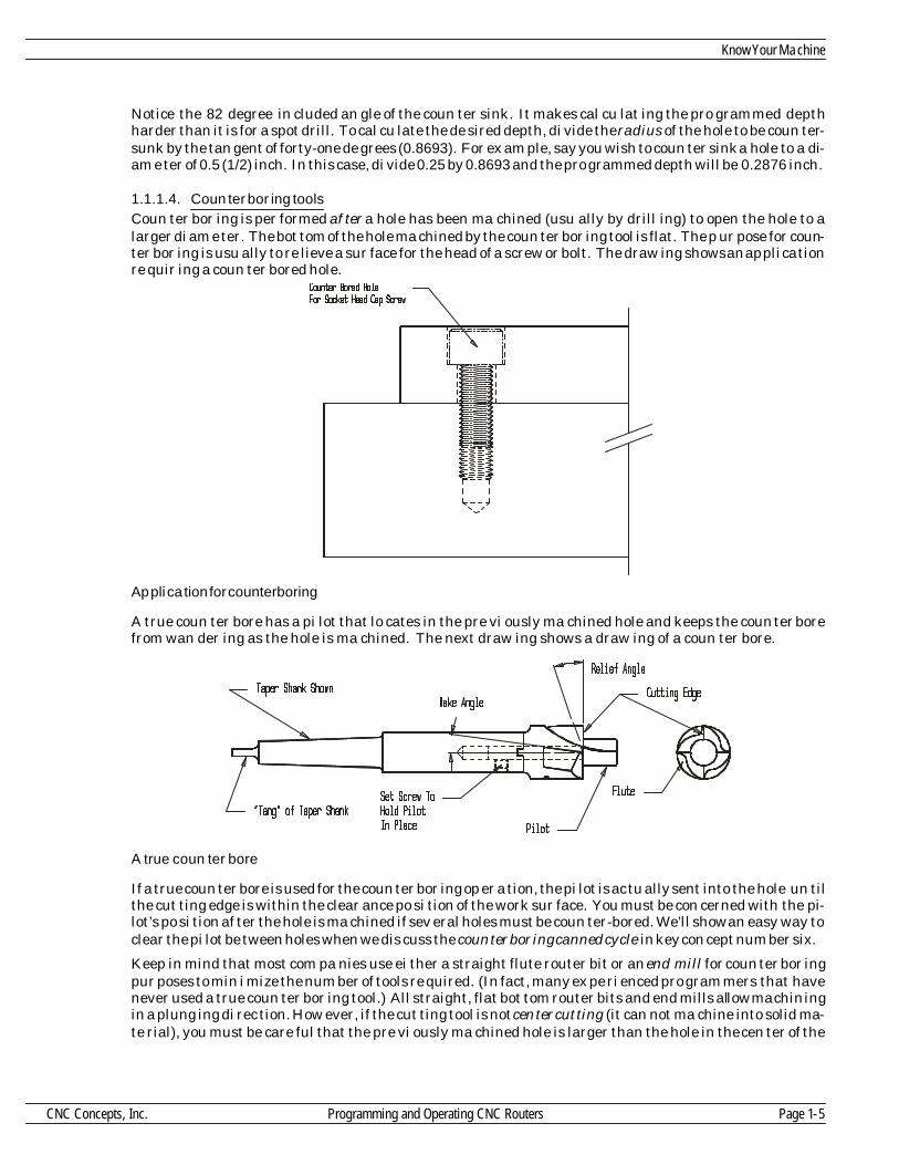
No tice the 82 de gree in cluded an gle of the coun ter sink. It makes cal cu lat ing the pro grammed depthharder than it is for a spot drill. To cal cu late the de sired depth, di vide the ra dius of the hole to be coun ter -sunk by the tan gent of forty-one de grees (0.8693). For ex am ple, say you wish to coun ter sink a hole to a di -am e ter of 0.5 (1/2) inch. In this case, di vide 0.25 by 0.8693 and the pro grammed depth will be 0.2876 inch.
1.1.1.4. Coun ter bor ing toolsCoun ter bor ing is per formed af ter a hole has been ma chined (usu ally by drill ing) to open the hole to alarger di am e ter. The bot tom of the hole ma chined by the coun ter bor ing tool is flat. The p ur pose for coun -ter bor ing is usu ally to re lieve a sur face for the head of a screw or bolt. The draw ing shows an ap pli ca tionre quir ing a coun ter bored hole.
Ap pli ca tion for counterboring
A true coun ter bore has a pi lot that lo cates in the pre vi ously ma chined hole and keeps the coun ter borefrom wan der ing as the hole is ma chined. The next draw ing shows a draw ing of a coun ter bore.
A true coun ter bore
If a true coun ter bore is used for the coun ter bor ing op er a tion, the pi lot is ac tu ally sent into the hole un tilthe cut ting edge is within the clear ance po si tion of the work sur face. You must be con cerned with the pi -lot’s po si tion af ter the hole is ma chined if sev eral holes must be coun ter-bored. We’ll show an easy way toclear the pi lot be tween holes when we dis cuss the coun ter bor ing canned cy cle in key con cept num ber six.
Keep in mind that most com pa nies use ei ther a straight flute router bit or an end mill for coun ter bor ingpur poses to min i mize the num ber of tools re quired. (In fact, many ex pe ri enced pro gram mers that havenever used a true coun ter bor ing tool.) All straight, flat bot tom router bits and end mills al low ma chin ingin a plung ing di rec tion. How ever, if the cut ting tool is not cen ter cut ting (it can not ma chine into solid ma -te rial), you must be care ful that the pre vi ously ma chined hole is larger than the hole in the cen ter of the
Know Your Ma chine
CNC Concepts, Inc. Programming and Operating CNC Routers Page 1-5
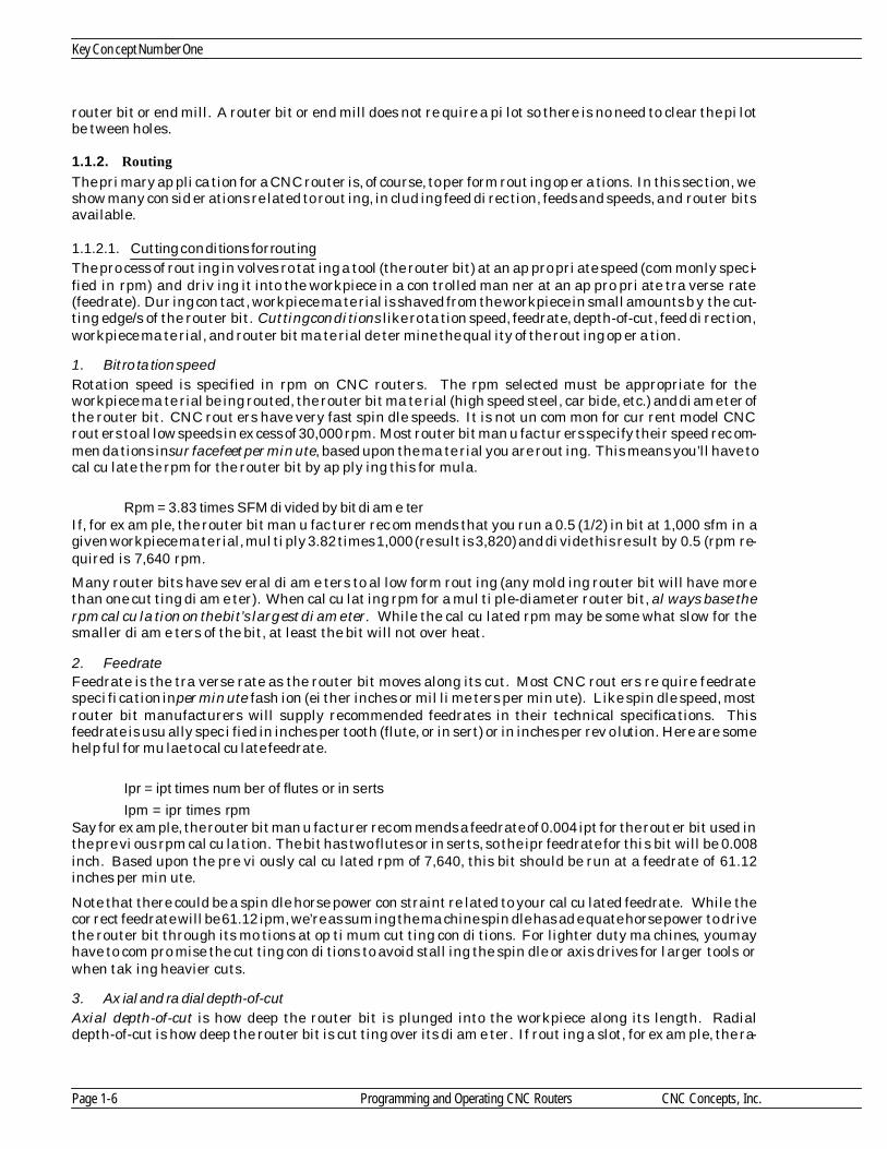
router bit or end mill. A router bit or end mill does not re quire a pi lot so there is no need to clear the pi lotbe tween holes.
1.1.2. Routing
The pri mary ap pli ca tion for a CNC router is, of course, to per form rout ing op er a tions. In this sec tion, weshow many con sid er ations re lated to rout ing, in clud ing feed di rec tion, feeds and speeds, and router bitsavail able.
1.1.2.1. Cut ting con di tions for rout ingThe pro cess of rout ing in volves ro tat ing a tool (the router bit) at an ap pro pri ate speed (com monly spec i -fied in rpm) and driv ing it into the workpiece in a con trolled man ner at an ap pro pri ate tra verse rate(feedrate). Dur ing con tact, workpiece ma te rial is shaved from the workpiece in small amounts b y the cut -ting edge/s of the router bit. Cut ting con di tions like ro ta tion speed, feedrate, depth-of-cut, feed di rec tion,workpiece ma te rial, and router bit ma te rial de ter mine the qual ity of the rout ing op er a tion.
1. Bit ro ta tion speedRo ta tion speed is spec i fied in rpm on CNC rout ers. The rpm se lected must be ap pro pri ate for theworkpiece ma te rial be ing routed, the router bit ma te rial (high speed steel, car bide, etc.) and di am e ter ofthe router bit. CNC rout ers have very fast spin dle speeds. It is not un com mon for cur rent model CNCrout ers to al low speeds in ex cess of 30,000 rpm. Most router bit man u fac tur ers spec ify their speed rec om -men da tions in sur face feet per min ute, based upon the ma te rial you are rout ing. This means you’ll have to cal cu late the rpm for the router bit by ap ply ing this for mula.
Rpm = 3.83 times SFM di vided by bit di am e terIf, for ex am ple, the router bit man u fac turer rec om mends that you run a 0.5 (1/2) in bit at 1,000 sfm in agiven workpiece ma te rial, mul ti ply 3.82 times 1,000 (re sult is 3,820) and di vide this re sult by 0.5 (rpm re -quired is 7,640 rpm.
Many router bits have sev eral di am e ters to al low form rout ing (any mold ing router bit will have morethan one cut ting di am e ter). When cal cu lat ing rpm for a mul ti ple-diameter router bit, al ways base therpm cal cu la tion on the bit’s larg est di am e ter. While the cal cu lated rpm may be some what slow for thesmaller di am e ters of the bit, at least the bit will not over heat.
2. FeedrateFeedrate is the tra verse rate as the router bit moves along its cut. Most CNC rout ers re quire feedratespec i fi ca tion in per min ute fash ion (ei ther inches or mil li me ters per min ute). Like spin dle speed, mostrouter bit man u fac tur ers will sup ply rec om mended feedrates in their tech ni cal spec i fi ca tions. Thisfeedrate is usu ally spec i fied in inches per tooth (flute, or in sert) or in inches per rev o lu tion. Here are somehelp ful for mu lae to cal cu late feedrate.
Ipr = ipt times num ber of flutes or in serts
Ipm = ipr times rpmSay for ex am ple, the router bit man u fac turer rec om mends a feedrate of 0.004 ipt for the router bit used inthe pre vi ous rpm cal cu la tion. The bit has two flutes or in serts, so the ipr feedrate for this bit will be 0.008inch. Based upon the pre vi ously cal cu lated rpm of 7,640, this bit should be run at a feedrate of 61.12inches per min ute.
Note that there could be a spin dle horse power con straint re lated to your cal cu lated feedrate. While thecor rect feedrate will be 61.12 ipm, we’re as sum ing the ma chine spin dle has ad e quate horse power to drivethe router bit through its mo tions at op ti mum cut ting con di tions. For lighter duty ma chines, youmayhave to com pro mise the cut ting con di tions to avoid stall ing the spin dle or axis drives for larger tools orwhen tak ing heavier cuts.
3. Ax ial and ra dial depth-of-cutAx ial depth-of-cut is how deep the router bit is plunged into the workpiece along its length. Ra dialdepth-of-cut is how deep the router bit is cut ting over its di am e ter. If rout ing a slot, for ex am ple, the ra -
Key Con cept Num ber One
Page 1-6 Programming and Operating CNC Routers CNC Concepts, Inc.
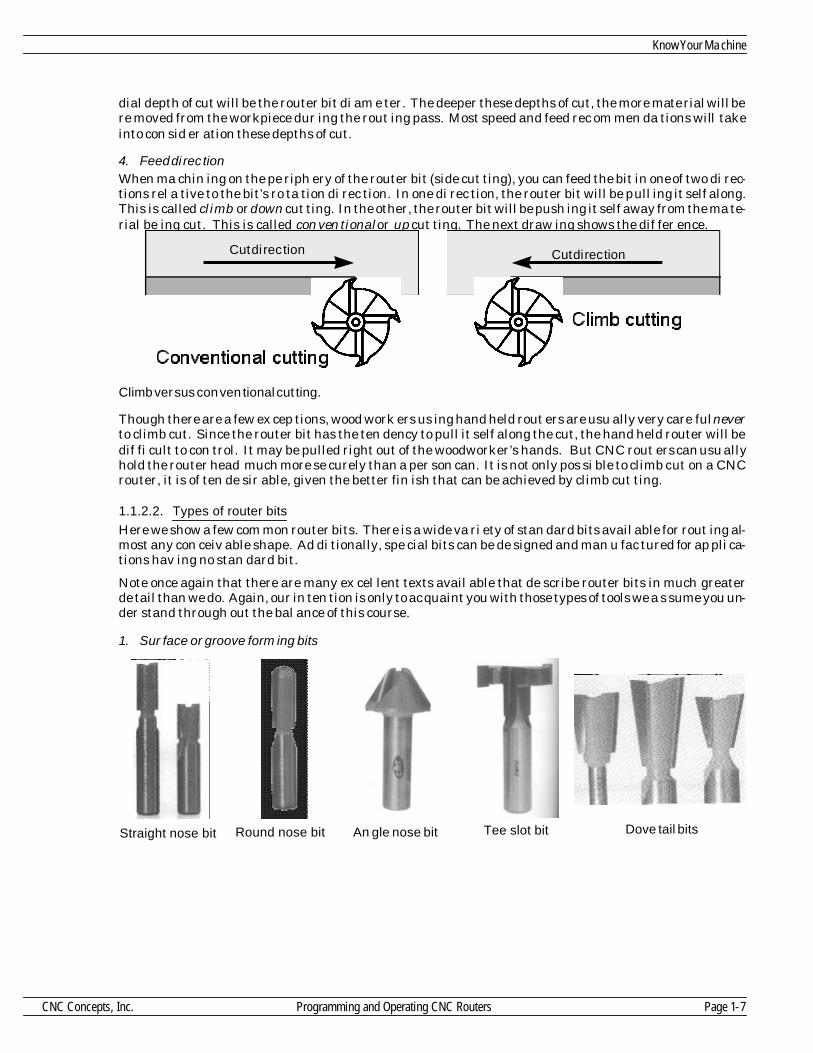
dial depth of cut will be the router bit di am e ter. The deeper these depths of cut, the more ma te rial will bere moved from the workpiece dur ing the rout ing pass. Most speed and feed rec om men da tions will takeinto con sid er ation these depths of cut.
4. Feed di rec tionWhen ma chin ing on the pe riph ery of the router bit (side cut ting), you can feed the bit in one of two di rec -tions rel a tive to the bit’s ro ta tion di rec tion. In one di rec tion, the router bit will be pull ing it self along.This is called climb or down cut ting. In the other, the router bit will be push ing it self away from the ma te -rial be ing cut. This is called con ven tional or up cut ting. The next draw ing shows the dif fer ence.
Climb ver sus con ven tional cut ting.
Though there are a few ex cep tions, wood work ers us ing hand held rout ers are usu ally very care ful neverto climb cut. Since the router bit has the ten dency to pull it self along the cut, the hand held router will bedif fi cult to con trol. It may be pulled right out of the woodworker’s hands. But CNC rout ers can usu allyhold the router head much more se curely than a per son can. It is not only pos si ble to climb cut on a CNCrouter, it is of ten de sir able, given the better fin ish that can be achieved by climb cut ting.
1.1.2.2. Types of router bits
Here we show a few com mon router bits. There is a wide va ri ety of stan dard bits avail able for rout ing al -most any con ceiv able shape. Ad di tionally, spe cial bits can be de signed and man u fac tured for ap pli ca -tions hav ing no stan dard bit.
Note once again that there are many ex cel lent texts avail able that de scribe router bits in much greaterde tail than we do. Again, our in ten tion is only to ac quaint you with those types of tools we a s sume you un -der stand through out the bal ance of this course.
1. Sur face or groove form ing bits
Know Your Ma chine
CNC Concepts, Inc. Programming and Operating CNC Routers Page 1-7
Straight nose bit Round nose bit An gle nose bit Tee slot bit Dove tail bits
Cut di rec tion Cut di rec tion
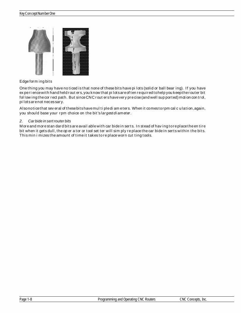
Edge form ing bits
One thing you may have no ticed is that none of these bits have pi lots (solid or ball bear ing). If you haveex pe ri ence with hand held rout ers, you know that pi lots are of ten re quired to help you keep the router bitfol low ing the cor rect path. But since CNC rout ers have very pre cise (and well sup ported) mo tion con trol,pi lots are not nec es sary.
Also no tice that sev eral of these bits have mul ti ple di am e ters. When it co mes to rpm cal c u la tion, again,you should base your rpm choice on the bit’s larg est di am e ter.
2. Car bide in sert router bitsMore and more stan dard bits are avail able with car bide in serts. In stead of hav ing to re place the en tirebit when it gets dull, the op er a tor or tool set ter will sim ply re place the car bide in serts within the bits.This min i mizes the amount of time it takes to re place worn cut ting tools.
Key Con cept Num ber One
Page 1-8 Programming and Operating CNC Routers CNC Concepts, Inc.

1.2. Ma chine con fig u ra tions
This sec tion ex plains the ba sic make-up of a CNC router. Most be gin ners tend to be a lit tle i n tim i datedwhen they see a CNC router in op er a tion for the first time. Ad mit tedly, there will be a num b er of new
func tions to learn. The first point to make is that you must not let the ma chine in tim i date you. As you goalong in this course, you will find that a CNC router is very log i cal and is al most easy to un d er stand withproper in struc tion. If you have pre vi ous ma chin ing ex pe ri ence with man u ally op er ated equip ment (likehand held rout ers and drill presses), you will find that most of what you al ready know about the ba sic ma -chin ing prac tice of woodworking will di rectly ap ply to CNC rout ers.
You can think of any CNC ma chine as be ing noth ing more than the stan dard type of equip ment it is re -plac ing (hand-held router, drill press, etc.) with a very so phis ti cated con trol added. In stead of ac ti vat ingthings man u ally by handwheels and man ual la bor, you will be pre par ing a pro gram that tells the ma -chine what to do. Vir tu ally any thing that needs to be done on a CNC router can be ac ti vated through apro gram.
1.2.1. CNC rout ers ver sus CNC woodworking ma chin ing cen ters
There are two ba sic types of CNC rout ers that we will be ad dress ing in this course. They are the CNCrouter and the CNC woodworking ma chin ing cen ter. For the pur pose of this course, about the only dif fer -ence is that the CNC ma chin ing cen ter has an au to matic tool chang ing (ATC) sys tem while the CNCrouter does not. Though there are ex cep tions, CNC rout ers tend to be smaller (some are even ta ble topsized) and less ex pen sive. Be cause they are so sim ple to work with, many com pa nies pur chase CNC rout -ers (as op posed to ma chin ing cen ters) as their first CNC ma chine.
There may be some other dif fer ences be tween CNC rout ers and ma chin ing cen ters hav ing to do with pro -gram ma ble fea tures. Some lower cost CNC rout ers, for ex am ple, may not have pro gram ma ble spin dles.In ad di tion to man u ally load ing the first tool, you may also have to ac ti vate the spin dle man u ally (turn iton in the de sired di rec tion at the proper speed) be fore you can ac ti vate the CNC pro gram. W ith full blownCNC ma chin ing cen ters, all ma chine func tions will be pro gram ma ble, min i miz ing the amount of op er a -tor in ter ven tion dur ing the CNC cy cle. Many of the ex am ples shown in this course as sume you’ll be work -ing with a full blown CNC ma chin ing cen ter.
1.2.1.1. Ba sic com po nents
Most CNC rout ers and ma chin ing cen ters in cor po rate a bridge de sign. The workpiece will be held in asta tion ary po si tion on the ma chine ta ble while the cut ting tools move around it to per form ma chin ing op -er a tions. This draw ing shows the ba sic com po nents for the most com mon style of CNC router and ma -chin ing cen ter.
Com po nents for a CNC router or ma chin ing cen ter
Know Your Ma chine
CNC Concepts, Inc. Programming and Operating CNC Routers Page 1-9
Opera tor’s position
He ads tock
S pindle
Columns
Bridge
Be dTa ble
CNC c ontrol

While de signs will vary from one router man u fac turer to an other, no tice that the headstock and spin dleare held atop the bridge. The workpiece is mounted, in one fash ion or an other to the ma chine ta ble. Whileworkpiece se cur ing de vices vary, a com mon work hold ing method is a vac uum-suction sys tem. With thisworkholding method, the work hold ing ta ble in cor po rates a vac uum sys tem to se curely hold workpiecesdur ing ma chin ing. Once the workpiece is placed in po si tion, the vac uum sys tem is ac ti vated dur ingworkpiece load ing from the op er a tor’s panel.
Most CNC rout ers in cor po rate an other style of vac uum sys tem to suck the chips from the work area.Though it may be pro gram ma ble, this de vice is also com monly ac ti vated from the op er a tor’s panel (withsome ma chines, this vac uum sys tem is au to mat i cally ac ti vated when the spin dle is turned on).
The cut ting tool held in the ma chine spin dle will move in at least three di rec tions. Each mo tion di rec tionis called an axis. The three most ba sic axes are lin ear, al low ing the cut ting tool to move along a per fectlystraight line. The next draw ing shows the nam ing and po lar ity of each mo tion di rec tion.
Di rec tions of mo tion for CNC rout ers
Though some CNC router man u fac tur ers stray from this stan dard, the lon gest axis is usu ally s pec i fied as the X axis. Note that the op er a tor stands on the other side of the ta ble, not on the side from which we’review ing. From the op er a tor’s po si tion, the X axis is usu ally the left/right di rec tion of mo tion. The Y axis is the fore/aft mo tion di rec tion (to ward and away from the op er a tor). And the Z axis is the spin dle mo tion di -rec tion to ward and away from the ta ble top (up/down). Most CNC rout ers in cor po rate a quill within thespin dle to form the Z axis.
At first glance the axis po lar i ties for X and Y may ap pear to be re versed. But no tice once again the po si -tion from which we are view ing this ma chine. The op er a tor ac tu ally stands on the other side of the ta ble.Tool mo tion to the op er a tor’s right is the X plus di rec tion. Tool mo tion away from the op e r a tor is Y plusmo tion.
One of the first things a CNC router pro gram mer must learn are the mo tion di rec tions (axes) and theirpo lar ity for the ma chine/s they will be pro gram ming. While most CNC rout ers and ma chin ing cen ters ad -here to the meth ods shown in the pre vi ous draw ings, you must con firm them for the ma chine/s withwhich you will be work ing. You may find that the X and Y axes are re versed. You may also find their po -lar i ties seem to be re versed. But re gard less of how your axes are ar ranged, once you can view the ma -chine from the proper per spec tive, you can eas ily ori ent the draw ings we show in this course to thema chine/s with which you will be work ing.
Key Con cept Num ber One
Page 1-10 Programming and Operating CNC Routers CNC Concepts, Inc.
Ope rator’s pos ition
X+
Y+
X-Y-
Z+
Z-

1.2.2. Other pro gram ma ble fea ture of CNC rout ers and ma chin ing cen ters
As men tioned, to day’s full blown woodworking ma chin ing cen ters al low the pro gram mer to con trol justabout any func tion re quired through pro grammed com mands. But re gard less of how many pro gram ma -ble func tions your CNC rout ers and ma chin ing cen ters have, it is very im por tant that you undersandwhat is pro gram ma ble. We can not be spe cific for your own com pany’s ma chines. You’ll have to checkwith an ex pe ri enced per son in your com pany or school, or look in your ma chine tool builder’s pro gram -ming man ual to de ter mine which ma chine func tions are pro gram ma ble.
Here we list the things that the pro gram mer can usu ally con trol within the pro gram and give a cur soryview of how each func tion is con trolled. Our in ten tion here is not to teach pro gram ming com mands (yet).It is to sim ply make you aware of the kinds of things a pro gram mer can con trol through a pro gram. Ifyou’ll be work ing with a CNC router (no au to matic tool changer), you’ll need to con firm which, if any, ofthese fea tures is pro gram ma ble.
1.2.2.1. Tool chang ing
Most CNC woodworking ma chin ing cen ters use a T word to spec ify which tool should be placed into theready or wait ing po si tion (just about to be placed in the ma chine’s spin dle) and an M06 to ac tu ally causethe tool change. For ex am ple, the com mand
T07 M06will place tool num ber seven into the spin dle. Most ma chines re quire that the Z axis be in a spe cial po si -tion to al low the tool change to oc cur. The tool change po si tion for most CNC ma chin ing cen ters is themachine’sZ axis zero re turn po si tion. We’ll de scribe the zero re turn po si tion a lit tle later in this key con -cept.
1.2.2.2. Spin dle speed
A pro gram mer can con trol pre cisely how fast the spin dle ro tates in one RPM in cre ments. An S word isused for this pur pose. If the pro gram mer wishes 2,350 RPM, the word S2350 is com manded.
1.2.2.3. Spin dle di rec tionA pro gram mer can also con trol which di rec tion the spin dle ro tates, for ward or re verse. The for ward di -rec tion is com monly used for right hand tool ing and the re verse di rec tion is used for left hand tool ing.Two M codes con trol this func tion. An M03 turns the spin dle on in the for ward di rec tion. M04 turns thespin dle on in a re verse di rec tion. Since al most all cut ting tools used with CNC rout ers are right hand,you’ll al most al ways be us ing M03 (for ward di rec tion) to start the spin dle. M05 turns the s pin dle off.
1.2.2.4. Feedrate
A pro gram mer can con trol the mo tion rate for any ma chin ing op er a tion. This is done with an F word. The F word spec i fies feedrate in per min ute mode. If you wish to work in the inch mea sure ment sys tem, thisfeedrate will be in inches per min ute. If you work in met ric, the feedrate will be in mil li me ters per min -ute. A feedrate of 3.5 inches per min ute is pro grammed as F3.5.
1.2.2.5. What else might be pro gram ma ble?
While this course will ac quaint you with the most com mon pro gram ma ble func tions of CNC rout e rs andma chin ing cen ters, you must be pre pared for more. Other fea tures that may be equipped on your ownma chines in clude ro tary axes (to al low the tool or workpiece to be ro tated dur ing ma chin ing op er a tions),air blow ing sys tems (to clear chips from the work area), and a va ri ety of other ap pli ca tion based fea tures.If you have any of these fea tures, you must ref er ence your ma chine tool builder’s pro gram ming man ual to learn how these spe cial fea tures are pro grammed.
STOP!! Do prac tice ex er cise num ber:
Know Your Ma chine
CNC Concepts, Inc. Programming and Operating CNC Routers Page 1-11
1

Les son 2
1.3. Gen eral flow of the pro gram ming pro cess
Though it is not di rectly re lated to the CNC router or ma chin ing cen ter it self, we want to in tro duce howthe typ i cal com pany us ing CNC equip ment would pro cess a job to be done on a CNC router. This should
help you un der stand the gen eral method by which CNC pro grams are pro cessed and should also help yougrasp the spe cific task of pro gram ming. In gen eral, it will help you see the big pic ture be fore div ing intolearn ing the more spe cific task of pro gram ming.
Here we give a ge neric ex am ple of how a typ i cal shop would han dle the CNC pro gram ming task. By nomeans will this flow be the same for all shops. Smaller shops tend to have one or two peo ple han dling allsteps in this flow. Larger man u fac tur ing com pa nies will usu ally break these steps up to be han dled bysev eral peo ple, pos si bly in dif fer ent de part ments.
1.3.1. De ci sion is made as to which CNC ma chine to use
If the com pany has more than one CNC router or ma chin ing cen ter, there may be some ques tion as towhich one to use. Based on the re quired num ber of workpieces, the size of the workpiece, the ac cu racy re -quired of the workpiece, the ma te rial to be ma chined, and the shop load ing on any one CNC router(among other things), a de ci sion is made as to which CNC ma chine to use.
1.3.2. The ma chin ing pro cess is de vel oped
If more than one op er a tion must be per formed by the CNC ma chine, some one with woodworking back -ground (per haps the pro gram mer) must come up with a se quence of op er a tions to be used to ma chine thepart. The pro gram will fol low the same se quence.
1.3.3. Tooling is or dered and checked
Based on a pre vi ously de vel oped pro cess, the re quired (workholding and cut ting) tool ing is ob tained. It ishelp ful early on in the pro cess to de ter mine what tool ing, if any, must be or dered.
1.3.4. The pro gram is de vel oped
In this step, the pro gram mer codes the pro gram into a lan guage that the CNC ma chine can un der stand.This step is, of course, one of the main fo cuses of this course. We pres ent six key con cepts to help you un -der stand this step.
1.3.5. Setup doc u men ta tion is made
Part of the pro gram mer’s re spon si bil ity is to make it clear as to how the set up is to be made at the ma -chine. Draw ings can be made to de scribe the work hold ing set up. If mul ti ple tools are to be used in thepro gram, some kind of tool list in clud ing the ma chine’s mag a zine sta tion num bers to be used for each tool. The more of ten a job is re peated, the more im por tant it is to doc u ment how the setup must be made.
1.3.6. Pro gram is loaded into the CNC con trol’s mem ory
Once the pro gram is pre pared, there are two com mon meth ods used to load it into the con trol’s mem ory.One way is for some one to phys i cally type it through the key board and dis play screen of the con trol panel.Gen erally speak ing, this is a rather cum ber some way to get the pro gram into the con trol’s mem ory. Forone thing, the key board of the con trol panel is quite dif fi cult with which to work. The key board is not ori -ented in a log i cal way (most are not like the key board of a type writer) and usu ally the panel it self ismounted ver ti cally, re sult ing in the per son typ ing the pro gram ex pe ri enc ing fa tigue. I n many cases, thema chine will sit idle while the pro gram is be ing typed. Even a rel a tively short pro gram could take thirtymin utes or more to en ter. A CNC ma chine makes a very ex pen sive type writer!
An other more pop u lar way to en ter pro grams into the con trol’s mem ory is to use some out side de vice fortyp ing pro grams. A desk top com puter can be used for the this pur pose. The soft ware used for this com -puter ap pli ca tion re sem bles a com mon word pro ces sor. In fact, most word pro ces sors can be used for thepur pose of typ ing CNC pro grams. Once the pro gram is en tered through the com puter’s key board, it canbe saved on the com puter’s floppy disk or hard drive. When the pro gram is needed at the ma chine, thepro gram can be quickly trans mit ted to the ma chine from the com puter. This trans mis sion takes place al -
Key Con cept Num ber One
Page 1-12 Programming and Operating CNC Routers CNC Concepts, Inc.
most in stan ta neously, even for lengthy pro grams. The com puter makes it much eas ier for the per sontyp ing the pro gram. They can sit in a much more com fort able en vi ron ment to type the pro gram. Most im -por tantly, the pro gram can be typed while the ma chine con tin ues in pro duc tion for the cur rent pro duc -tion run, mean ing al most no ma chine time is wasted while the pro gram is loaded.
1.3.7. The set up is made
Be fore the pro gram can be run, the workholding set up must be made. Using the set-up in struc tions(com monly pre pared by the pro gram mer), the set up per son makes the set up. Tooling is as sem bled andloaded into the proper lo ca tions. Mea sure ments must also be made to de ter mine the po si tion of pro gramzero and the length of each tool. And, in gen eral, any func tion re lated to the set-up must be done.
1.3.8. The pro gram is cau tiously ver i fied
It is very rare that a new pro gram re quires no mod i fi ca tion at the ma chine. Even if the pro gram mer doesa good job pro gram ming the mo tion re quired, there will al most al ways be some op ti miz ing nec es sary tore duce the cy cle time to the min i mum. Dur ing key con cept num ber ten we dis cuss pro gram ver i fi ca tion in great de tail.
1.3.9. Pro duc tion is run
At this point the ma chine is turned loose to run pro duc tion. While the pro gram mer’s job could be con sid -ered fin ished at this point, there may be some long term prob lems that do not pres ent them selves un tilsev eral workpieces are run. For ex am ple, tool wear may be ex ces sive. Tools may have to be re placed more of ten than the com pany would like. In this case, the speeds, feeds, and depths-of-cut in the pro gram mayhave to be ad justed.
1.3.10. Cor rected ver sion of the pro gram is stored for fu ture use
At least some workpieces run on CNC ma chines are run on a reg u lar ba sis, es pe cially in man u fac tur ingcom pa nies that pro duce a prod uct. At some fu ture date it will prob a bly be nec es sary to run the workpieceagain. If changes are nec es sary dur ing pro gram ver i fi ca tion, it will be nec es sary to trans mit the cor rectedCNC pro gram back to the pro gram stor age de vice for fu ture use. If the com pany must run the sameworkpieces again at some fu ture date, the cor rected ver sion of the pro gram must be kept. If this step isnot done, of course, the pro gram will have to be ver i fied a sec ond time.
STOP!! Do prac tice ex er cise num ber:
Know Your Ma chine
CNC Concepts, Inc. Programming and Operating CNC Routers Page 1-13
2

This page can be used for notes.
Key Con cept Num ber One
Page 1-14 Programming and Operating CNC Routers CNC Concepts, Inc.

Les son 3
1.4. Vi su al izing the ex e cu tion of a CNC pro gram
A CNC pro gram mer must have the abil ity to vi su al ize the move ments a CNC ma chine makes. This is true of all forms of CNC equip ment, in clud ing CNC rout ers and ma chin ing cen ters. The better a per son can
vi su al ize what the CNC router will be do ing, the eas ier it will be to pre pare a cor rect CNC pro gram. Tostress this point, think of how a man ual drill press op er a tor uses their ma chine.
When an drill press op er a tor pre pares to ma chine a workpiece, he or she has all re lated com p o nents of the job right in front of them. The ma chine, cut ting tools, workholding setup, and print are ready for im me di -ate use. It is highly un likely that the op er a tor will make silly mis takes like for get ting to start the spin dlebe fore try ing to drill a hole in the workpiece.
On the other hand, a CNC router or ma chin ing cen ter pro gram mer will be writ ing the pro gram w ith onlythe workpiece and tool ing draw ings for ref er ence. No tool ing - no ma chine - no workholding setup will bein front of them. For this rea son, the pro gram mer must be able to vi su al ize just ex actly what will hap pendur ing the ex e cu tion of the pro gram - and this can some times be dif fi cult, since vi su al iza tion must takeplace in the pro gram mer’s mind. A be gin ning pro gram mer will be prone to for get cer tain things - some -times very ba sic things (like turn ing the spin dle on prior to ma chin ing the workpiece).
This can be lik ened to de vel op ing a set of travel in struc tions. In or der to be able to writedown a set of travel in struc tions, you must be able to vi su al ize the path from the start pointto the end point. Only with this path vi su al ized, can you write down a se quen tialstep-by-step set of in struc tions to get a per son from point A to point B. If you make a mis -take in your set of travel in struc tions, the per son fol low ing your in struc tions will get lost.
In sim i lar fash ion, a CNC pro gram mer must be able to pre pare a set of step-by-step in struc -tions for a CNC router to fol low. And vi su al iz ing what the ma chine will be do ing is ev ery bitas im por tant, since the ma chine will fol low the com mands you give ex actly as you give them. Mis takes are ev ery bit as se ri ous. If you make a mis take, the CNC ma chine will not per form as de sired!
In this sec tion, we in tend to ac quaint you with those things a pro gram mer must be able tovi su al ize. We will also show the first (el e men tary) pro gram ex am ple to stress the points be ing made.
1.4.1. Pro gram make-up
Like the Eng lish sen tences mak ing up your set of travel in struc tions, a CNC pro gram is made up of com -mands (also called blocks or lines). Within each com mand are words. Each word within a com mand ismade up of a let ter ad dress (N, X, Z, T, etc.) and a nu mer i cal value. The next graphic shows an ex am plepor tion of a CNC pro gram stress ing pro gram make-up.
Pro gram make-up and ex e cu tion or der.
Know Your Ma chine
CNC Concepts, Inc. Programming and Operating CNC Routers Page 1-15
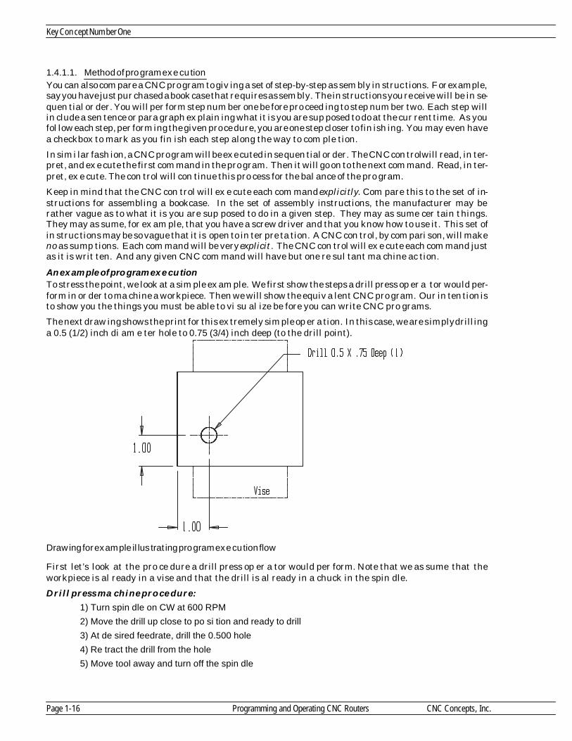
1.4.1.1. Method of pro gram ex e cu tionYou can also com pare a CNC pro gram to giv ing a set of step-by-step as sem bly in struc tions. For ex am ple,say you have just pur chased a book case that re quires as sem bly. The in struc tions you re ceive will be in se -quen tial or der. You will per form step num ber one be fore pro ceed ing to step num ber two. Each step willin clude a sen tence or para graph ex plain ing what it is you are sup posed to do at the cur rent time. As youfol low each step, per form ing the given pro ce dure, you are one step closer to fin ish ing. You may even havea checkbox to mark as you fin ish each step along the way to com ple tion.
In sim i lar fash ion, a CNC pro gram will be ex e cuted in se quen tial or der. The CNC con trol will read, in ter -pret, and ex e cute the first com mand in the pro gram. Then it will go on to the next com mand. Read, in ter -pret, ex e cute. The con trol will con tinue this pro cess for the bal ance of the pro gram.
Keep in mind that the CNC con trol will ex e cute each com mand ex plic itly. Com pare this to the set of in -struc tions for as sem bling a book case. In the set of as sem bly in struc tions, the man u fac turer may berather vague as to what it is you are sup posed to do in a given step. They may as sume cer tain things.They may as sume, for ex am ple, that you have a screw driver and that you know how to use it. This set ofin struc tions may be so vague that it is open to in ter pre ta tion. A CNC con trol, by com par i son, will makeno as sump tions. Each com mand will be very ex plicit. The CNC con trol will ex e cute each com mand justas it is writ ten. And any given CNC com mand will have but one re sul tant ma chine ac tion.
An ex am ple of pro gram ex e cu tionTo stress the point, we look at a sim ple ex am ple. We first show the steps a drill press op er a tor would per -form in or der to ma chine a workpiece. Then we will show the equiv a lent CNC pro gram. Our in ten tion isto show you the things you must be able to vi su al ize be fore you can write CNC pro grams.
The next draw ing shows the print for this ex tremely sim ple op er a tion. In this case, we are sim ply drill inga 0.5 (1/2) inch di am e ter hole to 0.75 (3/4) inch deep (to the drill point).
Draw ing for ex am ple il lus trat ing pro gram ex e cu tion flow
First let’s look at the pro ce dure a drill press op er a tor would per form. Note that we as sume that theworkpiece is al ready in a vise and that the drill is al ready in a chuck in the spin dle.
Drill press ma chine pro ce dure:1) Turn spin dle on CW at 600 RPM
2) Move the drill up close to po si tion and ready to drill
3) At de sired feedrate, drill the 0.500 hole
4) Re tract the drill from the hole
5) Move tool away and turn off the spin dle
Key Con cept Num ber One
Page 1-16 Programming and Operating CNC Routers CNC Concepts, Inc.

Ad mit tedly, this ex am ple is ex tremely sim ple. But keep in mind that we are stress ing the se quen tial or -der by which an op er a tor ma chines the workpiece and the vi su al iza tion of these steps that is man da tory in or der to write a CNC pro gram to drill this hole.
CNC pro gram:
Now here is a CNC pro gram to drill the 0.5 (1/2) inch di am e ter hole on a CNC router. Again, we as sumethat the drill is in the spin dle and that the workpiece is held in a vise on the ta ble when this pro gram be -gins. No tice that we doc u ment each com mand with a mes sage in pa ren the ses in or der to help you seewhat is hap pen ing dur ing each com mand. Note that you can in clude mes sages within pa ren the ses inyour own pro grams (though in ac tual pro grams they must be all in cap i tal let ters) for doc u m en ta tion pur -poses.
O0001 (Pro gram num ber)
N005 G54 G90 S600 M03 (As sign pro gram zero, se lect ab so lute mode, turn spin -dle on CW at 600 RPM)
N010 G00 X1.0 Y1.0 (Move the tool into po si tion in X and Y)
N015 G43 H01 Z0.1 (Rapid up to workpiece, in stat ing tool length com pen sa tion)
N020 G01 Z-0.750 F3.5 (Drill hole at 3.5 IPM)
N025 G00 Z0.1 (Rapid out of the hole, turn off cool ant)
N030 G91 G28 X0 Y0 Z0 (Rapid to the ma chine’s ref er ence po si tion)
N035 M30 (End of pro gram, this com mand also turns off spin dle)Though the ac tual com mands in this pro gram may not make much sense yet, the mes sages within pa ren -the ses should nicely clar ify what is hap pen ing in each com mand. Again, our in ten tion is not to teach thepro gram ming words be ing used (yet). Our in ten tion is to stress the im por tance of your abil ity to vi su al izethe op er a tion/s be ing per formed. In this case, you must be able to see the drill ma chin ing the hole (in yourmind) be fore this pro gram can be writ ten. We’re also stress ing the se quen tial or der by which the pro gram will be ex e cuted. The con trol will ex e cute line num ber N005 be fore mov ing on to line num b er N010. Then line num ber N015. And so on —un til the en tire pro gram is ac ti vated.
Also, you should now be able to see how your pre vi ous woodworking ex pe ri ence is go ing to help. If you canvi su al ize how you want tools to move, as shown in the drill press ex am ple, you are well on your way tolearn ing how to pro gram these move ments for a CNC router. In deed, if you can not vi su al ize how youwould want a tool to move as it per forms a ma chin ing op er a tion, you will not be able to write the CNC pro -gram. For those ma chin ing op er a tions with which you are not fa mil iar, you will (at the very least) needthe help of an ex pe ri enced woodworker.
1.4.1.2. A note about dec i mal point pro gram mingAs you have seen in the pre vi ous ex am ple pro gram, many CNC words al low a dec i mal point to be givenwithin a nu mer i cal value. All cur rent con trols al low dec i mal point pro gram ming in those words which re -quire real num bers (but not within words that sim ply re quire only in te ger [whole] val ues).
Be gin ning pro gram mers have the ten dency to leave out re quired dec i mal points, es pe cially when pro -gram ming in te ger val ues in words that al low a dec i mal point. It is man da tory that you in clude a dec i malpoint within each word that al lows a dec i mal point. If you do not, some very strange things can hap pen.Here’s why.
Older con trols do not al low a dec i mal point in any CNC word. These con trols re quire a fixed for mat for allreal num bers needed in the pro gram. Trailing ze ros are re quired for these older con trols to im ply wherethe dec i mal point should be placed. For ex am ple, an X mo tion word of 5.0 in would be spec i f ied as“X50000" if dec i mal point pro gram ming is not al lowed.
Newer con trols are up ward com pat i ble. This means pro grams writ ten for older con trols can still run incur rent con trols. If a cur rent CNC con trol sees a word that al lows a dec i mal point with out a dec i mal point in cluded in the word, it will sim ply place the dec i mal point au to mat i cally us ing the fixed for mat.
Here’s an ex am ple. Say the pro gram mer in tends to spec ify an X word of 3.0 in. The cor rect way to des ig -nate this move ment is “X3.0" But say the pro gram mer makes a mis take. He or she in cor rectly pro grams
Know Your Ma chine
CNC Concepts, Inc. Programming and Operating CNC Routers Page 1-17

”X3", leav ing out the dec i mal point. In this case, the con trol will in cor rectly in ter pret the X move ment.In stead of tak ing this com mand as 3.0 inches, the con trol will place the dec i mal point four places to the left of the right-most digit . In this case, “X3" will be taken as X0.0003, not 3.0 inches.
Re mem ber that be gin ning pro gram mers tend to make mis takes of omis sion , mean ing your ten dency willbe to omit the dec i mal point in CNC words that re quire it. Get in the habit of in clud ing a dec i mal pointwithin those words that al low it. These let ter ad dress words in clude: F for feedrate, I, J, & K, for cir cu larmo tion com mands, R for ra dius, and X, Y & Z for axis move ments. Words that do not al low a dec i mal pointand must be pro grammed as in te ger val ues in clude: N, G, H, D, L, M, S, T, O, and P.
One way to en sure that you will not for get to pro gram dec i mal points is to carry out whole num bers to thevery first zero (af ter the dec i mal point) for those words that al low dec i mal points. For ex am ple, pro gramX2.0 in stead of X2. to elim i nate the pos si bil ity of for get ting needed dec i mal points. In sim i lar fash ion,pro gram the lead ing zero when des ig nat ing dec i mal por tions of a whole num ber. For ex am ple, pro gramX0.375 in stead of X.375.
Note that al most all CNC con trols do re quire that for val ues un der one, you pro gram the dec i mal equiv a -lent. Though many prints show val ues with frac tional di men sions, you must con vert to dec i mal. Thevalue along the X axis of 3-15/16, for ex am ple, must be pro grammed as X3.9375.
1.4.1.3. Other mis takes of omis sion
Knowing the mis takes be gin ners are prone to make may help you avoid them. Be gin ners tend to for getthings in their pro grams. They for get to pro gram a dec i mal point. They for get to turn on the spin dle.They for get to drill a hole be fore coun ter-boring it. Much later, we will be show ing you ex a m ple pro gramfor mats that should help you avoid these mis takes of omis sion. But you will have to con cen trate veryhard to avoid ing be ing for get ful.
1.4.1.4. Modal wordsYou must know that many CNC words are modal. This means that the CNC word re mains in ef fect un tilchanged or can celed. In the pre vi ous ex am ple pro gram, no tice the G00 com mand in line N010. This hap -pens to be a rapid mo tion com mand that tells the con trol to move into po si tion in X and Y. No tice that thevery next (line N015) makes the move ment in Z to ap proach the workpiece. This move ment will also oc -cur as a rapid mo tion be cause G00 is modal. Modal words do not have to be re peated in ev ery com mand.
1.4.1.5. Ini tial ized words
You must also know that cer tain CNC words are in i tial ized. This means the CNC con trol will as sumethese words to be in stated at power-up. For ex am ple, most ma chines used in the US will come on in theinch mode (the in stat ing word hap pens to be G20). If a com pany will be ex clu sively us ing the inch mode,they can de pend upon the CNC con trol to be in this state at all times, mean ing there is no need to ac tu allyin clude a G20 in the pro gram.
1.4.1.6. Word or der in a commandNote that with most CNC con trols, the or der by which CNC words ap pear in a com mand has no bear ingupon how the com mand will be ex e cuted. For ex am ple, the com mand
N050 G00 X1.5 Y1.25 will be ex e cuted in ex actly the same way as
N050 X1.5 G00 Y1.25
STOP!! Do prac tice ex er cise num ber:
Key Con cept Num ber One
Page 1-18 Programming and Operating CNC Routers CNC Concepts, Inc.
3

Les son 4
1.5. Un der stand ing pro gram zero and the rect an gu lar co or di nate sys tem
The method by which po si tion ing move ment is com manded on CNC ma chines has been re fined over theyears. In the very early days of NC (well be fore com puter nu mer i cal con trol),the NC pro gram mer ac tu -
ally had to know how many ro ta tions of an axis drive mo tor equated to an inch of lin ear move ment. This,of course, made po si tion ing move ments very dif fi cult to pro gram. To day, thanks to the rect an gu lar co or -di nate sys tem, pro gram mers need not con cern them selves with the in ner work ings of each axis drive sys -tem in or der to com mand po si tion ing move ments. With the rect an gu lar co or di nate sys tem (also calledthe Car te sian co or di nate sys tem), po si tions, called co or di nates, are spec i fied with re spect to a cen tral or i -gin point.
To help you un der stand the rect an gu lar co or di nate sys tem, we give a sim ple anal ogy to mak ing and us ing a graph. Ev ery one has had to make, or at least use, a graph. The next il lus tra tion shows an ex am ple.
Graph ex am ple used to il lus trate rect an gu lar co or di nate sys tem.
This is a graph show ing a com pany’s pro duc tiv ity for last year. The hor i zon tal base line r ep re sents time.The in cre ment of time is spec i fied in months. In this case, the range for the hor i zon tal base line is onewhole year from Jan u ary through De cem ber. The ver ti cal base line rep re sents pro duc tiv ity. The in cre -ment for this base line is spec i fied in ten per cent in cre ments and it ranges from 0% to 100% p ro duc tiv ity.
In or der for a per son to make this graph, they would look up the pro duc tiv ity for Jan u ary and plot a pointalong the ver ti cal line cor re spond ing to Jan u ary and the per cent age of pro duc tiv ity (80% in our case).This plot ting of points would be re peated for ev ery month of the year. Once all the points are plot ted, aline or curve could be passed through each point to show any one at a glance how the com pany did lastyear.
The graph anal ogy is amaz ingly sim i lar to the rect an gu lar co or di nate sys tem as it is used with CNC. ForCNC rout ers and woodworking ma chin ing cen ters, the hor i zon tal base line will rep re sent the X axis. Thever ti cal base line will rep re sent the Y axis. (The Z axis is the di rec tion is at a right an gle to this page, to -ward and away from you.) The in cre ments of each base line are given in lin ear mea sure ment. For theinch mode (which we use through out this course), each in cre ment is given in inch. The small est in cre -ment is 0.0001 inch, mean ing each axis has a very fine grid. For the met ric mode, each in cre ment will be
Know Your Ma chine
CNC Concepts, Inc. Programming and Operating CNC Routers Page 1-19
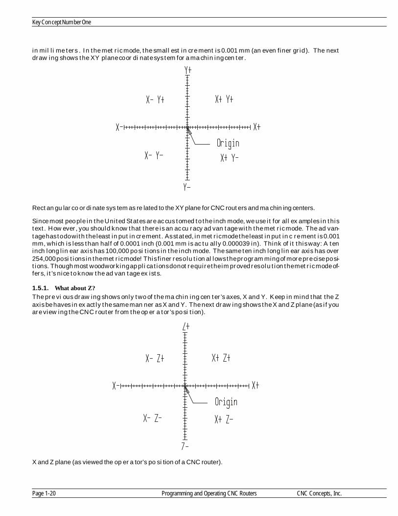
in mil li me ters . In the met ric mode, the small est in cre ment is 0.001 mm (an even finer grid). The nextdraw ing shows the XY plane co or di nate sys tem for a ma chin ing cen ter.
Rect an gu lar co or di nate sys tem as re lated to the XY plane for CNC rout ers and ma chin ing cen ters.
Since most peo ple in the United States are ac cus tomed to the inch mode, we use it for all ex am ples in thistext. How ever, you should know that there is an ac cu racy ad van tage with the met ric mode. The ad van -tage has to do with the least in put in cre ment. As stated, in met ric mode the least in put in c re ment is 0.001 mm, which is less than half of 0.0001 inch (0.001 mm is ac tu ally 0.000039 in). Think of it this way: A teninch long lin ear axis has 100,000 po si tions in the inch mode. The same ten inch long lin ear axis has over254,000 po si tions in the met ric mode! This finer res o lu tion al lows the pro gram ming of more pre cise po si -tions. Though most woodworking ap pli ca tions do not re quire the im proved res o lu tion the met ric mode of -fers, it’s nice to know the ad van tage ex ists.
1.5.1. What about Z?
The pre vi ous draw ing shows only two of the ma chin ing cen ter’s axes, X and Y. Keep in mind that the Zaxis be haves in ex actly the same man ner as X and Y. The next draw ing shows the X and Z plane (as if youare view ing the CNC router from the op er a tor’s po si tion).
X and Z plane (as viewed the op er a tor’s po si tion of a CNC router).
Key Con cept Num ber One
Page 1-20 Programming and Operating CNC Routers CNC Concepts, Inc.

When taken all to gether, the X, Y, and Z give you a three di men sional grid. It is within this grid that youwill be plot ting po si tions (co or di nates) that your tools will be pass ing through, as the next draw ing de -picts.
CNC rout ers al low tool po si tions to be plot ted in a three di men sional sys tem (X, Y, & Z)
1.5.2. Un der stand ing plus and minus
The point where the base lines in ter sect is called the or i gin. In the graph ex am ple, no tice that all pointswere plot ted af ter Jan u ary and above 0% pro duc tiv ity. The area up and to the right of the or i gin is calleda quad rant. This par tic u lar quad rant is quad rant num ber one. The per son cre at ing the pro duc tiv itygraph in ten tion ally planned for co or di nates to fall in quad rant num ber one in or der to make it easy toread the graph.
For CNC pur poses, we call this or i gin the pro gram zero point. There will be many times when co or di nates used within the CNC pro gram will not fall up and to the right of the pro gram zero point (quad rant num -ber one). Any co or di nates that do not fall into quad rant num ber one re quire at least one neg a tive po si tion (or di nate). Note that the CNC con trol will au to mat i cally as sume that a co or di nate is plus un less a mi nussign (-) is pro grammed within the co or di nate word. This means you never have to pro gram a plus sign (+).
The next draw ing takes the ex am ple a lit tle fur ther and shows how a se ries of co or di nates are de ter -mined. No tice that there is a se ries of holes around a cir cle that must be spec i fied rel a tive to the cen ter ofthe cir cle. That is, the cen ter of cir cle is the or i gin for the co or di nate sys tem. As you can see, any hole tothe left of the or i gin re quires a mi nus X co or di nate. Any hole be low the or i gin re quires a mi nus Y co or di -nate. And re mem ber, the CNC con trol will as sume plus un less mi nus is spec i fied.
Draw ing stresses plus and mi nus co or di nates in X and Y axes.
Know Your Ma chine
CNC Concepts, Inc. Programming and Operating CNC Routers Page 1-21

1.5.3. Pro gram zero
In the graph anal ogy, you know the graph has to start some where (where the base lines in ter sect ). In ourcase, it started at Jan u ary for the hor i zon tal base line and 0% pro duc tiv ity for the ver ti cal base line. When mak ing graphs, this start ing point for each base line is called the or i gin point.
For use with CNC, the or i gin point for each axis is most com monly called the pro gram zero point. Alsocalled work zero, part or i gin , and zero point, the pro gram zero point al lows the pro gram mer to in put all co -or di nates used in a pro gram from a com mon and log i cal point. This point is usu ally the lo c a tion on theprint from which all (or the most) di men sions are taken. One of the main ben e fits of us ing the rect an gu lar co or di nate sys tem to com mand po si tion ing move ments is that many of the co or di nates used within thepro gram can be taken right from the print.
In the graph, each base line has a name, an in cre ment, and a range. For the hor i zon tal base line, thename is time, the in cre ment is given in one month in ter vals, and the range is from Jan u ary through De -cem ber (one year). For the ver ti cal base line, the name is pro duc tiv ity, the in cre ment is ten per cent in ter -vals, and the range is from zero to one hun dred per cent.
As stated ear lier, each base line of the rect an gu lar co or di nate sys tem rep re sents a ma chine axis (X, Y, orZ). The in cre ment for each base line is re lated to the mea sure ment sys tem. If work ing in t he inch mode,most CNC rout ers will have a in cre ment of 0.0001 inch (this is com monly called the ma chine’s least in putin cre ment or res o lu tion ). In met ric mode, the in cre ment is usu ally 0.001 mil li me ters. The range of eachbase line is the over all length of travel for the axis it rep re sents. If you have a CNC router with a sev -enty-two inch X axis, the range for your ma chine’s X axis is sev enty-two inches.
1.5.4. Where to place your pro gram zero point
The place ment of pro gram zero is de ter mined by the pro gram mer. Pro gram zero could be placed any -where. As long as the co or di nates in the pro gram are spec i fied from the pro gram zero point, the ma chinewill move prop erly. Though this is the case, the wise se lec tion of a log i cal pro gram zero point will makepro gram ming and setup eas ier.
We rec om mend that you make your pro gram zero point a lo ca tion on the workpiece from which the di -men sions in your pro gram start. If the de sign en gi neer uses da tum sur face dimensioning, the pro gramzero point se lec tion will be easy. Just make it the da tum sur face on the workpiece for each axis. If the de -sign en gi neer does not use da tum sur face dimensioning, they will al most al ways be gin the dimensioningfrom one sur face in each axis. This will be your pro gram zero point. If you’re still in doubt, ask your selfwhat sur faces you will be us ing to lo cate the workpiece in the ma chine for setup pur poses. This sur face ineach axis usu ally cor re sponds to the pro gram zero point.
Once the pro gram zero point has been se lected, all axis po si tions (co or di nates) go ing into the pro gramwill be taken from this point. If you se lect the pro gram zero point at the da tum surface on the print for allaxes, di men sions go ing into your pro gram will be taken right from your print, min i miz ing the need to per -form cal cu la tions in or der to come up with pro gram co or di nates.
Much of the work done on CNC rout ers and es pe cially CNC woodworking ma chin ing cen ters is done inrect an gu lar flat stock (com monly cut from 4’ x 8’ ply wood, fi ber board, etc.). Board thick ness is com monlyin the neigh bor hood of from 3/16 through one inch. The fin ished workpiece is also com monly square orrect an gu lar in shape. For these workpieces, pro gram zero will usu ally be one of the cor ners. Cal cu latingco or di nates will usu ally be pretty easy since most de sign en gi neers will spec ify all X and Y re lated di men -sions from one cor ner. How ever, it will of ten be nec es sary to po si tion the workpiece on the ma chine ta blein a way by which it can be eas ily lo cated (bumped against X and Y pro gram zero sur faces). The nextdraw ing shows an ex am ple.
Key Con cept Num ber One
Page 1-22 Programming and Operating CNC Routers CNC Concepts, Inc.

Workpiece draw ing
How workpiece is held on the ma chine ta ble
The da tum sur face dimensioning makes it easy to de ter mine the XY pro gram zero point (lower left handcor ner of the workpiece). All X and Y co or di nates will be pos i tive (+). How ever, it just so hap pens that theori en ta tion of this draw ing nicely cor re sponds to the way the bump stops are lo cated on the ta ble. Con -sider the next ex am ple.
Workpiece draw ing
Know Your Ma chine
CNC Concepts, Inc. Programming and Operating CNC Routers Page 1-23
1
1
3
15
17 17.5
5
1.5
ControlOpe ra tor a re a
Swing a wa y bump stops
Program zero
Y+
X+
1
1
3
15
17 17.5
5
1.5

Now the pro gram zero point is the up per left hand cor ner of the workpiece. You can han dle this prob lemin one of three ways. First of all, if all of the ma chin ing on this workpiece goes all the way through theworkpiece (through holes and pock ets), the workpiece can sim ply be flipped and run up side-down (top ofthe workpiece down). In this case, the workpiece can still be bump-stopped against the lower left hand lo -ca tors. But any ma chin ing does not go through the workpiece, an other al ter na tive must be found.
The sec ond way to han dle this prob lem is to move the lo ca tors. The next draw ing shows one way to do so.
One way the workpiece is held on the ma chine ta ble
Note that if this is done, the X lo ca tor can re main in the same po si tion and the Y axis lo ca tors must bemoved. Also, all Y axis co or di nates will be mi nus (-).
A third al ter na tive is to ro tate the workpiece 180 de grees and lo cate it in the ta ble from the right end. Inthis case only the (one) X axis lo ca tor must be moved for setup. If this al ter na tive is cho sen, you’ll have toro tate the print in or der to come up with the pro gram co or di nates. Also, all X co or di nates will be mi nus(-).
An other way to lo cate the workpiece on the ma chine ta ble
Key Con cept Num ber One
Page 1-24 Programming and Operating CNC Routers CNC Concepts, Inc.
ControlOpera tor are a
Progra m zero
Y-
X+Alte rna tive one
ControlOpe rator a rea
Alte rna tive two
P rogra m ze ro
Y+
X-

As you can see, se lect ing the ap pro pri ate pro gram zero point com monly re quires that you con sider howthe workpiece will be lo cated on the ma chine ta ble dur ing ma chin ing. Only then can you come up with co -or di nates needed in the pro gram.
1.5.4.1. What about Z?As with XY, the pro gram mer must des ig nate a pro gram zero po si tion in the Z axis. We rec om mend thatyou make the pro gram zero sur face in Z the top sur face of the workpiece. With this method, any ma chin -ing that oc curs in the workpiece (be low the top sur face) will re quire a mi nus (-) Z axis co or di nate. We willuse this tech nique for Z axis pro gram zero se lec tion through out the course.
1.5.4.2. Ex am ple show ing how co or di nates are cal cu latedHere is a draw ing dimensioned with da tum sur face dimensioning. No tice that pro gram zero will be thelower left hand cor ner of the workpiece in X and Y. It will be the top sur face of the workpiece in Z. Thisworkpiece can be eas ily lo cated on the ma chine ta ble in the same re la tion ship the draw ing i s made, mean -ing the X co or di nates will be spec i fied along the long side of this workpiece while the Y co o r di nates will bespec i fied along the short side.
No tice that all points re quired in the pro gram are num bered, in clud ing the po si tions needed for the 3/4router. Here is a co or di nate sheet show ing the X, Y, and Z val ues needed in the pro gram. Again, no ticethat all co or di nates spec i fied on the co or di nate sheet are given rel a tive to the pro gram zero point. Forpoints one through six (for the 3/4 inch router bit), no tice that X co or di nates are spec i fied to the cen ter ofthe dado.
Know Your Ma chine
CNC Concepts, Inc. Programming and Operating CNC Routers Page 1-25

Co or di nate sheet
1.5.5. Ab so lute vs incremen tal
When you are spec i fy ing co or di nates from the pro gram zero point (as we rec om mend), it is called the ab -so lute mode of pro gram ming. The ab so lute mode is spec i fied by a G90 word in the pro gram. Ab so lutemode dif fers from an older (yet still some times help ful) po si tion ing mode of pro gram ming called in cre -men tal mode. With in cre men tal mode, the pro gram mer com mands each move ment from the tool’s cur -rent po si tion.
In the in cre men tal mode (spec i fied by G91) the pro gram mer com mands move ments from the tool’s cur -rent po si tion. Each move ment is spec i fied as an in cre men tal dis tance and di rec tion from the tool’s cur -rent lo ca tion. While at first glance this may seem eas ier than work ing from pro gram zero, you will findthat in cre men tal mo tions are very dif fi cult to fol low. Also, if the pro gram mer makes a mis take in a se riesof in cre men tal mo tions, ev ery in cre men tal move ment from that point on will be in cor rect. If the pro gram -mer makes the same mis take in a pro gram writ ten in ab so lute mode, only one move ment will be in cor -rect. In the ab so lute mode, the ma chine will be back on track with the next cor rectly spec i fied po si tion.While there are some ex cel lent ap pli ca tions for in cre men tal mode (times when in cre men tal mode candra mat i cally shorten a pro gram’s length), and we’ll show them in key con cept num ber six, be gin ning pro -gram mers should con cen trate on work ing ex clu sively in the ab so lute mode. But keep in mind that any mo -tion can be com manded in ei ther the ab so lute or in cre men tal mode. The next il lus tra tion shows this.
Move ments made in both the ab so lute and in cre men tal mode.
Key Con cept Num ber One
Page 1-26 Programming and Operating CNC Routers CNC Concepts, Inc.
# X Y Z
1 3.375 16.475 -0.375
2 3.375 -0.475 -0.375
3 15.375 -0.475 -0.375
4 15.375 7.0 -0.375
5 29.625 -0.475 -0.375
6 29.625 16.475 -0.375
7 6.75 14.0 0.1/-0.45
# X Y Z
9 8.75 14.0 0.1/-0.45
10 9.75 14.0 0.1/-0.45
11 10.75 14.0 0.1/-0.45
12 11.75 14.0 0.1/-0.45
13 12.75 14.0 0.1/-0.45
14 6.75 2.0 0.1/-0.45
15 7.75 2.0 0.1/-0.45
# X Y Z
17 9.75 2.0 0.1/-0.45
18 10.75 2.0 0.1/-0.45
19 11.75 2.0 0.1/-0.45
20 12.75 2.0 0.1/-0.45
As you can see, ab so lute co or di nates make sense. They match print di men sions. In cre men tal mo tions donot. They are noth ing more than a whole se ries of small move ments, each taken from the tool’s pre vi ouspo si tion.
1.5.5.1. Warn ing about think ing incrementallyWe must warn you that be gin ners tend to make mis takes with re gard to ab so lute and in cre men tal modes. Be gin ners tend to think incrementally, spec i fy ing mo tions as dis tances from the tool’s last po si tion whenthey should be spec i fy ing po si tions from the pro gram zero point. When com ing up with co or di natesneeded for your pro gram ask your self, “to what po si tion will the tool be mov ing in this com mand?” Thispo si tion must be spec i fied rel a tive to the pro gram zero point. Be gin ners tend to ask them selves thewrong ques tion. They tend to ask, “how far should the tool move in this com mand?” That’s think ingincrementally.
1.5.6. Be sure to use the dec i mal point when spec i fy ing axis po si tions
Though dec i mal point pro gram ming is in tro duced in les son three, it is a very im por tant fea ture for co or di -nate en try and we want to de scribe its use in fur ther de tail. As stated, when ever you want to make thema chine move along one or more of the axes, you will be spec i fy ing the co or di nate to which you want tomake the tool move. To do this, you must al ways spec ify the let ter ad dress of the axes you wish to move (X, Y, and/or Z) along with the co or di nate po si tion to which the tool must move. The co or di nate po si tion value tells the con trol where along the axis to stop the tool.
Cur rent con trols al low you to spec ify this co or di nate po si tion with a dec i mal point. Older con trols (overabout 20 years old) do not al low the dec i mal point. You must re mem ber to use a dec i mal point in all ofyour pro gram’s co or di nate po si tions. One tech nique you can use to help you re mem ber the d ec i mal pointis to in clude at least one digit to the right and left of the dec i mal point. When writ ing whole num bers, forex am ple, carry your value to the first zero to the right of the dec i mal point. Write
X3.0for ex am ple, in stead of
X3.In sim i lar fash ion, in clude the zero to the left of the dec i mal point when writ ing val ues un der one. Write
X0.5in stead of
X.5Again, this will help you keep from for get ting to write or type dec i mal points when writ ing or en ter ingpro grams.
As you have seen, it is much eas ier to read a pro gram if it con tains co or di nates with dec i m al points. Hereare a few ex am ples of CNC words in clud ing dec i mal points.
3.125 in the Y axis would be spec i fied as Y3.125
2.12731 in the X axis would be rounded to X2.1273
3 inches in the Z axis would be spec i fied as Z3.0
4.75 in the X axis would be spec i fied as X4.75Though we have been dis cuss ing co or di nate po si tions, you will also find that as dec i mal point can be in -cluded in other types of CNC words when it is fea si ble to do so. For ex am ple, the feedrate com mand (Fword) also al lows a dec i mal point.
As men tioned, older con trols (over about twenty years old) do not al low dec i mal point pro gram ming. For -tu nately, CNC is rel a tively new to the woodworking in dus try, mean ing that rel a tively few older CNCrout ers ex ist that do not al low dec i mal point pro gram ming.
With these older ma chines that do not al low dec i mal point pro gram ming, a fixed for mat must be usedwith real num bers (num bers in clud ing a dec i mal por tion). Keep in mind that this method of des ig nat ingpo si tions is still al lowed, even on cur rent model con trols. Here are some ex am ples that as sume four placetrail ing zero fixed for mat.
3.125 in the Y axis would be spec i fied as Y31250
2.12731 in the X axis would be rounded to X21273
Know Your Ma chine
CNC Concepts, Inc. Programming and Operating CNC Routers Page 1-27

3 inches in the Z axis would be spec i fied as Z30000
4.75 in the X axis would be spec i fied as X47500Note that in all cases, the value is car ried out to the fourth place to the right of the dec i mal point. The con -trol will au to mat i cally place the dec i mal point four places to the left of the right-most digit.
This should give you a clue about what will hap pen if you for get to in clude a dec i mal point in a word thatre quires it. If for ex am ple, you in tend an X po si tion of three inches (should be spec i fied X3.0) and for getthe dec i mal point (spec i fy ing X3), the con trol will au to mat i cally place the dec i mal point four places to theleft of the right-most digit (3 in our case). It will take the value spec i fied in X3 as X0.0003 in stead of X3.0.Again, it is very im por tant that you in clude the dec i mal point in words that re quire it.
While most man ual pro gram mers pre fer to use dec i mal point pro gram ming for ob vi ous rea sons, note that some com puter aided man u fac tur ing (CAM) sys tems still gen er ate CNC pro grams with out dec i malpoints. If your com pany owns this kind of CAM sys tem, you must, of course, be able to rec og nize the valueof each CNC word, even if it does not have a dec i mal point.
STOP!! Do prac tice ex er cise num ber:
Key Con cept Num ber One
Page 1-28 Programming and Operating CNC Routers CNC Concepts, Inc.
4
Les son 5
1.6. Lo cating the pro gram zero point for a pro gram
At this early point in the course, it is much more im por tant that you un der stand the pro -gram-zero-related top ics pre sented thus far than it is to know how pro gram zero is lo cated and as -
signed. How ever, you must know that just be cause you want the pro gram zero point to be in a cer tainplace does n’t mean the CNC con trol will au to mat i cally know its cho sen lo ca tion. In re al ity, a con scious ef -fort must be made to as sign the pro gram zero point. Think of it this way. The pro gram mer de ter mines alog i cal po si tion for the pro gram zero point. All co or di nates go ing into the pro gram are spec i fied from thispoint. How ever, the CNC ma chin ing cen ter or router con trol must also know the lo ca tion of the pro gramzero point in or der to make the ma chine move cor rectly. In es sence, when the setup per son as signs pro -gram zero, they are mar ry ing the pro gram to the work hold ing set up.
By one means or an other, the con trol must be told the lo ca tion of the pro gram zero point in or der to makethe ma chine move prop erly. In les son 6, you will learn that there are two ways by which pro gram zero can be as signed. With ei ther method, the tech niques shown in this les son can be used to find or mea sure thepro gram zero point at the ma chine.
Both meth ods we show in les son 6 re quire that you know the dis tance be tween your se lected pro gramzero point and the ma chine’s spin dle while all axes of the ma chine are rest ing at the ma chine’s zero re -turn po si tion. The method we show to lo cate the pro gram zero point for the ma chine is rather crude. It re -quires mea sure ments to be taken right on the ma chin ing cen ter af ter the work hold ing setup is made.While there are tech niques that can min i mize (or even elim i nate) these te dious, time con sum ing, and er -ror prone mea sure ments, the method we show does make it easy to un der stand what the pro gram zero as -sign ment val ues rep re sent.
1.6.0.1. What is the zero re turn po si tion?There are two zero po si tions that will be of con stant con cern to you while you are work ing withFanuc-controlled CNC rout ers and ma chin ing cen ters. First is the pre vi ously dis cussed pro gram zero po -si tion. You now know that pro gram zero is the lo ca tion on your workpiece from which all co or di nates go -ing into your pro gram are taken.
The sec ond zero point is the ma chine’s zero re turn po si tion (some peo ple call this po si tion home position,ma chine zero, grid zero po si tion , or ref er ence position). The zero re turn po si tion is a very ac cu rate lo ca tion along each of the ma chine’s axes which acts as a point of ref er ence for pro gram zero as sign ment. In fact,the ma chine start-up pro ce dure for most ma chines re quires that you send each axis to its zero re turn po -si tion. When the ma chine is sent to its zero re turn po si tion, three axis or i gin lights come on (one for eachaxis) to in di cate that the ma chine is rest ing at its zero re turn po si tion.
For most CNC rout ers and woodworking ma chin ing cen ters, the zero re turn po si tion is close to the ex -treme plus limit of each axis. When a CNC router is rest ing at zero re turn po si tion, the col umn is all theway to the right in X (as viewed from the op er a tor sta tion), the headstock is as far as it can move awayfrom the op er a tor in Y, and the quill is all the way up in Z.
The zero re turn po si tion is the lo ca tion from which you will mea sure the pro gram zero point. Fur ther -more, de pend ing upon how pro gram zero is as signed, the zero re turn po si tion may also be the lo ca tionfrom which you will ac tu ally ex e cute your pro gram (more on this in les son 6).
1.6.1. How to mea sure the pro gram zero point lo ca tion on the ma chine
The next il lus tra tion shows the X and Y pro gram zero as sign ment val ues that must be de ter m ined be forepro gram zero can be as signed. No tice that the ma chine is rest ing at its zero re turn po si tion in this il lus -tra tion.
Know Your Ma chine
CNC Concepts, Inc. Programming and Operating CNC Routers Page 1-29

XY axes pro gram zero as sign ment val ues
Again, the X and Y axis pro gram zero as sign ment val ues are the dis tances be tween the pro gram zeropoint and the cen ter line of the spin dle while the ma chine is rest ing at its zero re turn po si tion. The Z axispro gram zero as sign ment value is de pend ent upon how you in tend to use a fea ture called tool length com -pen sa tion. We dis cuss this tool length com pen sa tion in key con cept num ber four. By our rec om mendedmethod, the pro gram zero as sign ment value in the Z axis will be the dis tance be tween the pro gram zeropoint and the spin dle nose in the Z axis. The next il lus tra tion shows the pro gram zero as sign ment valuefor the Z axis us ing the method we rec om mend.
Z axis pro gram zero as sign ment value
There are many ways to ac tu ally mea sure the pro gram zero as sign ment val ues at the ma chine dur ingsetup. But re mem ber that these mea sure ments take time, and if you can come up with a way to elim i natethese mea sure ments, you can save a lot of setup time. We’ll dis cuss get ting more ef fi cient a lit tle later.For now, we just want to show one way these val ues can be mea sured.
Key Con cept Num ber One
Page 1-30 Programming and Operating CNC Routers CNC Concepts, Inc.
ControlOpe ra tor a rea
Progra m ze ro
Y+
X+
X program va lue
Y a xisvalue
Ze ro re turn pos ition
Progra m zero
Spindle nose
Z a xisvalue
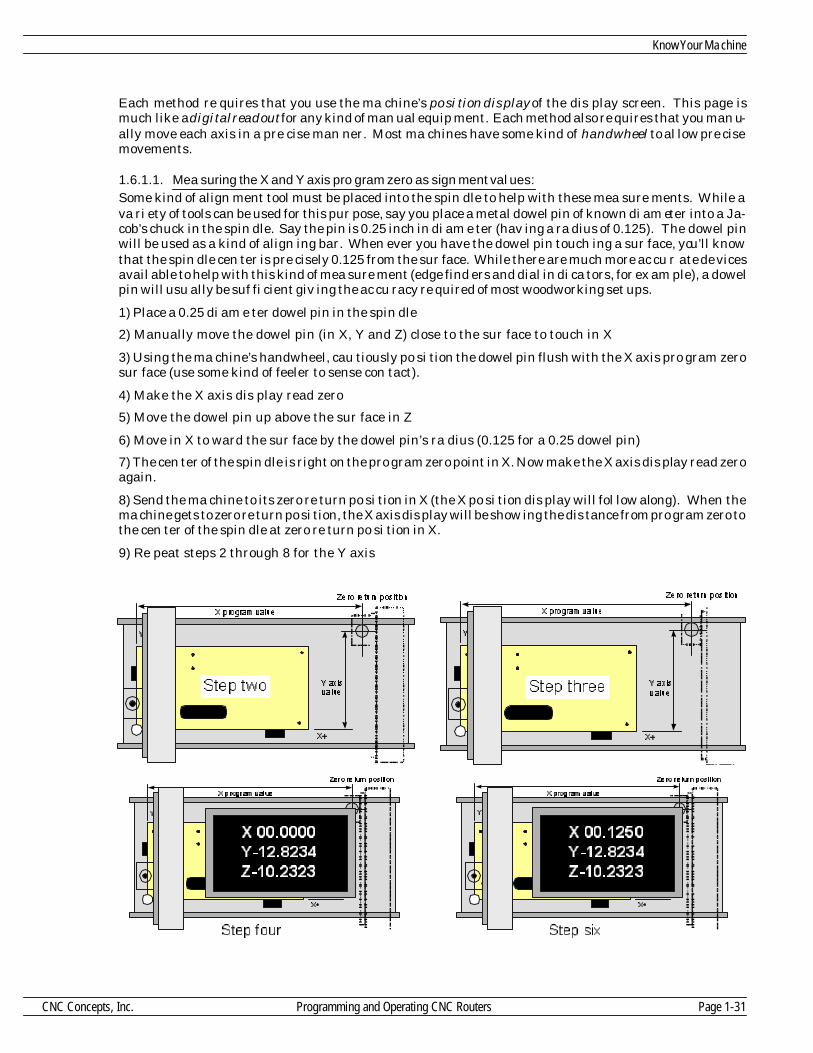
Each method re quires that you use the ma chine’s po si tion dis play of the dis play screen. This page ismuch like a dig i tal read out for any kind of man ual equip ment. Each method also re quires that you man u -ally move each axis in a pre cise man ner. Most ma chines have some kind of handwheel to al low pre cisemove ments.
1.6.1.1. Mea suring the X and Y axis pro gram zero as sign ment val ues:Some kind of align ment tool must be placed into the spin dle to help with these mea sure ments. While ava ri ety of tools can be used for this pur pose, say you place a metal dowel pin of known di am e ter into a Ja -cob’s chuck in the spin dle. Say the pin is 0.25 inch in di am e ter (hav ing a ra dius of 0.125). The dowel pinwill be used as a kind of align ing bar. When ever you have the dowel pin touch ing a sur face, you’ll knowthat the spin dle cen ter is pre cisely 0.125 from the sur face. While there are much more ac cu r ate de vicesavail able to help with this kind of mea sure ment (edge find ers and dial in di ca tors, for ex am ple), a dowelpin will usu ally be suf fi cient giv ing the ac cu racy re quired of most woodworking set ups.
1) Place a 0.25 di am e ter dowel pin in the spin dle
2) Manually move the dowel pin (in X, Y and Z) close to the sur face to touch in X
3) Using the ma chine’s handwheel, cau tiously po si tion the dowel pin flush with the X axis pro gram zerosur face (use some kind of feeler to sense con tact).
4) Make the X axis dis play read zero
5) Move the dowel pin up above the sur face in Z
6) Move in X to ward the sur face by the dowel pin’s ra dius (0.125 for a 0.25 dowel pin)
7) The cen ter of the spin dle is right on the pro gram zero point in X. Now make the X axis dis play read zeroagain.
8) Send the ma chine to its zero re turn po si tion in X (the X po si tion dis play will fol low along). When thema chine gets to zero re turn po si tion, the X axis dis play will be show ing the dis tance from pro gram zero tothe cen ter of the spin dle at zero re turn po si tion in X.
9) Re peat steps 2 through 8 for the Y axis
Know Your Ma chine
CNC Concepts, Inc. Programming and Operating CNC Routers Page 1-31

1.6.1.2.To mea sure the pro gram zero as sign ment value in Z:
1) With noth ing in the spin dle, man u ally move the nose of the spin dle down close to the pro gram zero sur -face in Z
2) Cau tiously touch the nose of the spin dle to the pro gram zero sur face
3) Make the Z axis dis play read zero
4) Manually send the ma chine to its zero re turn po si tion. When the Z axis reaches the zero re turn po si -tion, the Z axis dis play will be show ing the dis tance from pro gram zero to the nose of the spin dle in Z.
Key Con cept Num ber One
Page 1-32 Programming and Operating CNC Routers CNC Concepts, Inc.
Y+
X+
X prog ra m va lue
Y a xisvalue
Ze ro re tu rn pos ition
X 65.3474Y-12.8234Z-10.2323
Ste p e ight
Z a xisva lue
Step one
X-25.2324Y-12.8234Z -08.1232 Z axis
va lue
Ste p two
X-25.2324Y-12.8234Z -08.9223
Z a xisva lue
Step thre e
X-25.2324Y-12.8234Z 00.0000 Z axis
va lue
Ste p four
X-25.2324Y-12.8234Z 8.37826

Note: Again, the pro ce dure for mea sur ing the Z axis dis tance may change based on your method of us ingtool length com pen sa tion. More on this dur ing key con cept num ber four.
1.6.1.3. Do you have to phys i cally mea sure the pro gram zero point?
While the steps just given should help you un der stand how pro gram zero as sign ment val ues can be mea -sured, mea sur ing pro gram zero for ev ery setup will take a lot of setup time. If you can elim i nate thesemea sure ments, you can dra mat i cally re duce setup time. Due to the con sis tent na ture of workpieces ma -chined on CNC rout ers and ma chin ing cen ters (square or rect an gu lar flat stock), many com pa nies canmount lo ca tion blocks (stops) in a semi-permanent man ner. If the stop-blocks don’t move from on e setupto an other, the pro gram zero as sign ment val ues in X and Y won’t change.
Ad di tionally, once the Z axis pro gram zero as sign ment value has been de ter mined for one stock thick -ness, it will re main the same ev ery time a workpiece of that thick ness is run. And of course, i t will be quite easy to de ter mine the Z axis pro gram zero as sign ment val ues for workpieces of other thick nesses withsim ple ad di tion and sub trac tion (no need for more Z measurments). In re al ity, most CNCrouter-using-companies don’t have to mea sure pro gram zero for ev ery setup. By ap ply ing a lit tle in ge nu -ity, some never have to mea sure it.
Also keep in mind that most con trols al low you to pro gram the pro gram zero as sign ment val ues, mean ingyou can even elim i nate the en try of pro gram zero as sign ment val ues. More on ways to im prove setup ef fi -ciency will be pre sented in key con cept num ber four.
STOP!! Do prac tice ex er cise num ber:
Know Your Ma chine
CNC Concepts, Inc. Programming and Operating CNC Routers Page 1-33
5

Les son 6
1.7. The two ways to as sign pro gram zero
In this les son we show the tech niques used to ac tu ally as sign the pro gram zero point. As stated in les sonfive, it is much more im por tant at this time that you un der stand how to de ter mine the pro gram zero
point’s po si tion and work in the ab so lute mode than it is to ac tu ally as sign pro gram zero.
Ad mit tedly mea sur ing and as sign ing pro gram zero is more a setup per son’s re spon si bil ity than a pro -gram mer’s (and we do show these tech niques from a setup per son’s point of view in key con cept num berseven). How ever, in most com pa nies the CNC pro gram mers is ex pected to pro vide di rec tion to the setuppeo ple and op er a tors. In deed, in key con cept num ber two, you’ll see that pro gram mers are com monly ex -pected to pro vide setup and pro duc tion run doc u men ta tion. In or der to do so, they must know as much assetup peo ple about pro gram zero as sign ment.
By far, the best way of as sign ing pro gram zero is to do so with a fea ture called fix ture offsets. In fact, theonly rea son not to use fix ture off sets is if your ma chine does not have the fea ture. If your ma chine has fix -ture off sets, we urge you to use fix ture off sets to as sign pro gram zero. Un for tu nately, not all con trolshave fix ture off sets. With out fix ture off sets, the only way to as sign pro gram zero is to do so within thepro gram with a G92 com mand. Be fore go ing much fur ther, you should con firm whether or not the ma -chines you’ll be work ing with have fix ture off sets. (Ask an ex pe ri enced per son in your com pany or schoolor check with your ma chine tool builder.)
With ei ther method of as sign ing pro gram zero, you use the pro gram zero as sign ment val ues dis cussed inthe last les son for pro gram zero as sign ment.
1.7.1. Ad van tages of as sign ing pro gram zero with fix ture off sets
As stated, fix ture off sets make a much better way of as sign ing pro gram zero. Here are some rea sons why.
1.7.1.1. Safety
A G92 com mand within the pro gram sim ply tells the con trol how far it is from pro gram zero to the spin dleat the cur rent time. When this com mand is used to as sign pro gram zero, each axis of the ma chine must bein a pre vi ously planned lo ca tion be fore the cy cle can be ac ti vated. If the ma chine is out of po si tion for anyrea son, the ma chine will not move to the cor rect lo ca tion. If the ma chine is moved in a mi nus di rec tion (inany axis) from its planned start ing point, the dis tance the ma chine will tra verse will be greater than itshould be, in ef fect, caus ing a col li sion be tween the tool and workpiece. This is the sin gle larg est cause ofcrashes on ma chin ing cen ters: When pro gram zero is as signed in the pro gram and the ma chine i s out of po -si tion when the cy cle is ac ti vated! With fix ture off sets, the ma chine need not be in a pre vi ously plannedpo si tion prior to ac ti vat ing the cy cle. In ef fect, the con trol will track the ma chine’s cur rent po si tion andtake it into con sid er ation when the pro gram zero as sign ment is in voked.
1.7.1.2. Ease of use
If pro gram zero is as signed in the pro gram, the op er a tor must be cer tain that the ma chine is in the properlo ca tion prior to ac ti vat ing a cy cle. This could re quire te dious man ual move ments to the ma chine’s zerore turn po si tion. With fix ture off sets, the op er a tor need not worry about send ing the ma c hine to a spe cificlo ca tion (other than pos si bly the ma chine’s tool change po si tion) prior to ac ti vat ing the cy cle.
1.7.1.3. Ef fi ciency
Since the ma chine must be in a pre cise lo ca tion prior to ac ti vat ing a cy cle if pro gram zero is as signed inthe pro gram, many wasted mo tions must be pro grammed the be gin ning of the pro gram, pos si bly dur ingeach tool change, and at the end of the pro gram. These mo tions just to get the ma chine to its proper start -ing po si tion, and can be very time con sum ing.
1.7.1.4. Re running toolsThe op er a tor will of ten need to re-run a given tool in the pro gram. Doing so if pro gram zero is as signed inthe pro gram can be some what dif fi cult, since the ma chine must be prop erly po si tion prior to re run ning
Key Con cept Num ber One
Page 1-34 Programming and Operating CNC Routers CNC Concepts, Inc.

the tool. Ad di tionally, the G92 com mand must be ex e cuted prior to re-starting. When as sign ing pro gramzero with fix ture off sets, no prior po si tion ing move ments are nec es sary.
1.7.2. As signing pro gram zero with fix ture off sets (G54-G59)
Fix ture off sets al low you to sep a rate the pro gram zero as sign ment from the CNC pro gram. The pro gramzero as sign ment val ues (shown in les son five) will be en tered on a spe cial dis play screen page. This draw -ing shows the fix ture off set page.
Fix ture off set page of a pop u lar CNC router con trol
The tech niques to ac tu ally en ter pro gram zero as sign ment val ues into fix ture off sets will be shown in keycon cept num bers four and nine. Fix ture off sets are spec i fied from the ma chine’s zero re turn po si tion to the pro gram zero point. Since the zero re turn po si tion is close to the plus limit of each axis on most CNC rout -ers, the po lar ity of fix ture off set val ues will al most al ways be mi nus.
An other ben e fit of fix ture off sets is that you can have up to (at least) six co or di nate sys tems. This meansup to six pro gram zero points, or co or di nate, sys tems, can be as signed. This can be used for mul ti pleworkpieces in a set up. For now we will limit our dis cus sions to uti liz ing this fea ture for only one co or di -nate sys tem.
Ac ti vating fix ture off sets from the pro gram is very sim ple. G54 spec i fies that you want to work in co or di -nate sys tem num ber one. G55 is for co or di nate sys tem num ber two, and so on through co or di nate sys temnum ber six (G59). When the con trol reads a G54 com mand, it looks to the val ues in cluded in the G54 fix -ture off set to at tain the dis tances from zero re turn po si tion to pro gram zero.
Using fix ture off sets (G54-G59) to as sign pro gram zero is must safer than us ing G92. Since all mea sure -ments are taken to the zero re turn po si tion, and since the mea sured val ues are not part of the pro gram,the con trol will al ways keep track of the ma chine’s po si tion. This means that if the ma chine is not at theplanned start ing lo ca tion when the cy cle is ac ti vated, the con trol will still send the tool to the proper lo ca -tion. As we said, if this were done while the G92 tech nique was used, a crash could oc cur.
For now, that’s enough about fix ture off sets. We’ll dis cuss their spe cial use for as sign ing mul ti ple pro -gram zero points in key con cept num ber four.
1.7.3. As signing pro gram zero in the pro gram
As stated, this is the less de sir able of the two meth ods used to as sign pro gram zero. On some con trols, itmay be the only way to as sign pro gram zero.
Ad di tionally, some pro gram mers as sign pro gram zero within the pro gram with G92 to main tain com pat i -bil ity with older equip ment. Some com pa nies have sev eral CNC rout ers that range in age from very old to quite new. A com pany’s older ma chines might re quire the G92 method of as sign ing pro gram zero. Tomain tain com pat i bil ity through out the shop, a pro gram mer may de cide to stick with its use. How ever,we urge peo ple not to use G92 com mand un less you don’t have fix ture offets.
Know Your Ma chine
CNC Concepts, Inc. Programming and Operating CNC Routers Page 1-35
When G92 is used to as sign pro gram zero within the pro gram, the pro gram mer will sim ply in clude themea sured dis tances from pro gram zero to the ma chine’s start ing po si tion (shown in les son 5) within theG92 com mand. This com mand is given very close to the be gin ning of the pro gram.
No tice that the dis tance is taken from the pro gram zero point to the ma chine’s start ing po si tion. For al -most all CNC rout ers and ma chin ing cen ters, this means the po lar ity of all G92 val ues will be pos i tive.
Here is an ex am ple of a G92 com mand as sum ing the pro gram zero as sign ment val ues are 10.0712 in X,13.7192 in Y, and 12.9281 in Z.
N005 G92 X10.0712 Y13.7192 Z12.9281
Again, no tice that the X, Y, and Z val ues in the G92 com mand are the dis tances mea sured from pro gramzero to the cen ter line of the spin dle in X and Y and to the nose of the spin dle in Z (shown ear lier) and willal most al ways be pos i tive val ues.
When the con trol reads this com mand, it sets the ab so lute po si tion dis plays on the con trol screen to the X,Y, and Z val ues of the G92 com mand it self. Ba sically, the con trol is be ing told that the dis tance from pro -gram zero to the cur rent cen ter line of the spin dle in X is 10.0712 inches. In Y the cur rent dis tance frompro gram zero to the cen ter line of the spin dle is 13.7192. And in Z, the dis tance from pro gram zero to thecur rent po si tion of the spin dle nose is 12.9281 inches.
No tice the word cur rent in each of the three pre vi ous sen tences. This is a very im por tant word. The use ofthe G92 com mand in the pro gram re quires that the op er a tor be ex tremely care ful with the pro gram’sstart ing point. If the pro gram is in tended to be run with the ma chine rest ing at the zero re turn po si tion,the op er a tor must be sure the ma chine is at zero re turn po si tion be fore they press the cy cle start but ton. If the op er a tor moves the ma chine axes out of po si tion (maybe to check a tool in the spin dle), when cy clestart is pressed the con trol would as sume that the G92 com mand di men sions are the dis tance from thepro gram zero point to the ma chine’s cur rent po si tion. If the ma chine was moved to ward the w orkpiece,the con trol will try to send the tool through the workpiece, caus ing a col li sion. Again, this is the big gestsource of crashes; when the op er a tor presses the cy cle start but ton while the ma chine is not at its properstart ing point.
When as sign ing pro gram zero in the pro gram, the ma chine’s zero re turn po si tion does make an ex cel lentpo si tion from which to start, es pe cially for be gin ners. Though it may not be the most ef fi cient po si tionfrom which to start the pro gram, at least the op er a tor can eas ily con firm that the ma chine i s at its properstart ing po si tion be fore the cy cle is ac ti vated. Three green axis or i gin lights will come on when the ma -chine is at zero re turn po si tion, in di cat ing to the op er a tor that it is safe to start the cy cle. If zero re turn isused as the pro gram’s start ing point, it is wise to make a com mand to send the ma chine to the zero re turnpo si tion prior to the G92 com mand. This will help save a crash if the ma chine has been moved out of po si -tion.
One com mand that can be used to send the ma chine to its zero re turn po si tion is as fol lows (more on howthis com mand works dur ing key con cept num ber five):
N005 G91 G28 X0 Y0 Z0
N010 G92 X10.0712 Y13.7192 Z12.9281No tice that this com mand is given just prior to the G92 com mand. The pro gram mer can rest as sured thatthe ma chine will be at the zero re turn po si tion when the G92 is read. It is a very nice safety en hanc ingtech nique.
STOP!! Do prac tice ex er cise num ber:
Key Con cept Num ber One
Page 1-36 Programming and Operating CNC Routers CNC Concepts, Inc.
6

Les son 7
1.8. In tro duc tion to pro gram ming words
Now is as good a time as any to in tro duce the var i ous words in volved with pro gram ming. If you are a be -gin ner look ing at these words for the first time, you may want to read this sec tion sev eral times to get
better ac quainted with these word types. Note that we are not ask ing you to mem o rize these CNC words.When we get into the pro gram for mat ting con cept (con cept num ber five), we will be giv ing you a way tosim ply look at each word and try to re mem ber its func tion. In key con cept num ber five, you will not haveto be able to come up with all the words used in pro gram ming com pletely on your own.
Also, this sec tion of the course is sim ply in tended to in tro duce each word, not to give you an in-depth de -scrip tion. You will find that cer tain words are sel dom used, mean ing you will have lit tle or no need forthem. Other words are con stantly used, and you will soon have them mem o rized af ter writ ing a few pro -grams.
Some pro gram ming words have more than one func tion, de pend ing on com mand for mat. We will beshow ing you the pri mary func tion of the word next to the “A” de scrip tion and any sec ond ary use for theword next to the “B” de scrip tion.
As a be gin ner, do not let the num ber of dif fer ent words in tim i date you. You will find that most of them are aptly named, hav ing the let ter stand for some thing that is easy to re mem ber, like “S” for spin dle speed,“F” for feedrate, and “T” for tool sta tion. It should not be too dif fi cult to re mem ber the func tion of mostwords. Ad di tionally, you will find that only thirty to forty words are used con sis tently when pro gram -ming, so look at learn ing CNC pro gram ming as like learn ing a for eign lan guage that has only thirty orforty words.
1.8.1. Note About Dec i mal Points
Re mem ber that all cur rent con trols al low the pro gram mer to in clude a dec i mal point for those word typesthat are fea si ble to use a dec i mal point with. Older con trols do not. Those word types that do al low dec i -mal points are:
A, B, C, X, Y, Z, I, J, K, F, Q, R, A, B, and C
Know Your Ma chine
CNC Concepts, Inc. Programming and Operating CNC Routers Page 1-37

O This is the word most con trols use for a pro gram num ber. All con trols dis cussed in thiscourse (Fanuc and Fanuc-compatible) al low the user to store mul ti ple pro grams in themem ory of the con trol. The pro gram mer will be as sign ing the pro gram a num ber from0001 through 9999. The O word will be the very first word in the pro gram. No dec i malpoint is al lowed with the O word.
N This word spec i fies a se quence num ber. A se quence num ber is used for pro gram lineiden ti fi ca tion. It al lows the pro gram mer to or ga nize each line in his pro gram by num ber.This al lows easy ed it ing of a pro gram at the ma chine. Se quence num bers are not re quired to be in any par tic u lar or der and can even re peat in the pro gram. Also, they do not evenhave to be in the pro gram at all. But for the sake of or ga ni za tion pur poses, we rec om -mend that be gin ners in clude them in the pro gram and place them in an un der stand ableor der. For ex am ples in this text, we will go by fives to al low for ex tra lines to be in serted ifneeded. No dec i mal point is al lowed with the N word.
G This code spec i fies what is called a pre pa ra tory func tion. Pre pa ra tory func tions al lowvar i ous modes to be set in the pro gram. There are many G words, but only a few that areused on a con sis tent ba sis. Most are modal, but a few are one-shot (non-modal). For a listof all G codes, see the list at the end of this hand out. No dec i mal point is al lowed withmost G words.
X A. The pri mary use for the X word is to des ig nate a co or di nate along the X axis. The Xword can be spec i fied with a dec i mal point or with out. With the dec i mal point, an X po si -tion of 10 inches would be spec i fied “X10.0". With out the dec i mal point the X word will goback to an old method of pro gram ming called fixed for mat. With out the dec i mal point anX po si tion of 10 inches would be spec i fied ”X100000", and the dec i mal point would be as -sumed to be four places from the right digit. For be gin ning pro gram mers, it is much eas -ier to pro gram with the dec i mal point, but you must be sure to in clude it in ev ery X word,or the ma chine will re vert to the fixed for mat. The same thing goes for the Y, Z, R, I, J, K,Q, and F words.
B. The sec ond ary use for the X word is that it can be used to spec ify the length of time in adwell com mand (see G04).
Y The Y word spec i fies a po si tion along the Y axis. All dec i mal point re lated func tions arethe same as for the X word.
Z A. The pri mary use for the Z word is to spec ify a po si tion along the Z axis. All dec i malpoint re lated func tions are the same as for the X word.
B. The sec ond ary use for the Z word is to spec ify the hole bot tom po si tion in a canned cy cle com mand. Canned cy cles are dis cussed in key con cept num ber six.
A If your ma chine has a ro tary ta ble of some kind (not a sim ple in dex ing de vice), the ro ta -tion of the de vice is con sid ered a true axis of mo tion, just like X, Y, and Z. De pending onthe style of the ma chine (hor i zon tal vs ver ti cal) the ro tary axis can be des ig nated with t he let ter ad dress A, B, or C. Gen erally speak ing, ver ti cal ma chin ing cen ters that have thero tary axis call the ro tary axis the C axis. Hor i zon tal ma chin ing cen ters call the ro taryaxis the B axis. How ever, some build ers do not fol low this stan dard. If your ma chine hasa ro tary ta ble, you must con sult your builder’s man ual to find out what they have namedthe ro tary axis.
B See the de scrip tion for “A”.
Key Con cept Num ber One
Page 1-38 Programming and Operating CNC Routers CNC Concepts, Inc.

C See the de scrip tion for “A”.
R A. The pri mary use for the R word is to spec ify the ra dius of a cir cu lar move. All dec i mal point re -lated func tions are the same as for the X word.
B. The sec ond ary use for the R word is to spec ify the rapid plane for a canned cy cle com mand.Canned cy cles are dis cussed in key con cept num ber six.
I A. I, J, and K words are the old way to spec ify the arc in a cir cu lar move. While they are still ef fec -tive, we strongly rec om mend that the be gin ner con cen trate on us ing the R word to spec ify the arcin a cir cu lar move. (It is much eas ier!) If us ing I, J, and K, these words spec ify the dis tance and di -rec tion in X, Y, and Z (I=X, J=Y, K=Z) from the start ing point of the arc to the cen ter of the arc.While I, J, and K do al low a full cir cle to be gen er ated in one CNC com mand, they are quite dif fi -cult for a be gin ner to un der stand. The R word is much more un der stand able. The I, J, and K fol -low the same dec i mal point rules as the X word.
J See de scrip tion of “I”.
K See de scrip tion of “I”.
Q The Q word is used with peck drill ing canned cy cles to spec ify the peck depth for each pass.Canned cy cles are dis cussed in key con cept num ber six. All dec i mal point re lated for mat re latedto the “X” word ap ply to the Q word.
P The P word is used to spec ify the length of time in sec onds for a dwell com mand. Dwell com mands are used to make the axis mo tion (for all axes) pause for a spec i fied length of time. The P wordspec i fies this length of time. A time of three sec onds would be spec i fied as P3000 (with NO dec i -mal point). Note that the fixed for mat of the P word has three places to the right of where the dec i -mal point would be. Other ex am ples: P2500 = 2.5 sec onds, P500 = .5 sec ond, and P10000 = 10sec onds. No dec i mal point is al lowed with the P word.
B. The sec ond ary use for the P word is with sub rou tines to spec ify the sub rou tine pro gram num -ber to be searched. Sub rou tines are dis cussed in key con cept num ber six. No dec i mal point is al -lowed with the P word.
L A. The L word is used with sub-programming tech niques (dis cussed in key con cept num ber six) to spec ify the num ber of times a sub-program should be ex e cuted. No dec i mal point is al lowed withthe L word.
B. The L word can also be used with canned cy cles (dis cussed dur ing key con cept num ber six) tospec ify the num ber of holes to ma chine. No dec i mal point is al lowed with the L word.
F The F word spec i fies the de sired feedrate in inches per min ute (IPM) or mil li me ters per min ute.This word is used to tell the con trol the de sired tra verse rate in a cut ting com mand (G01, G02,and G03). The F word al lows a dec i mal point, so a feedrate of 3-1/2 inches per min ute would bepro grammed “F3.5". How ever with out the dec i mal point, the fixed for mat is slightly dif fer e ntthan the X word. ”F350" would be the “fixed for mat” for a feedrate of 3.5 inches per min ute. Notethat the mean ing of the “F” word changes based on in put mode. In the inch mode (G20), thefeedrate is spec i fied in inches per min ute. In the met ric mode (G21), the feedrate is spec i f ied inmil li me ters per min ute.
Know Your Ma chine
CNC Concepts, Inc. Programming and Operating CNC Routers Page 1-39

S The S word spec i fies a spin dle speed. Most cur rent ma chines al low the pro gram mer tospec ify the ex act RPM they de sire. That is, a spin dle speed of 350 RPM would be pro -grammed “S350". No dec i mal point is al lowed with the S word. Though it may not be ex -tremely im por tant at this early point in the course, if the ma chin ing cen ter has more than one spin dle range, many ma chines will have the con trol key on the S word value to de ter -mine the ap pro pri ate spin dle range. Say for ex am ple, your ma chine has two spin dleranges. The low range runs from 30-4,000 rpm. The high range runs from 4,001 through10,000 rpm. For this ma chine, a speed se lec tion of S300 would au to mat i cally force thema chine to se lect the low range. A spin dle speed se lec tion of S5000 would have the ma -chine se lect the high spin dle range.
T With most ma chines, the T word spec i fies a two digit tool sta tion to be placed in the loadpo si tion of the tool changer mag a zine. While one tool is cut ting, it is com mon to se lect theT word of the next tool so that when the tool in the spin dle is fin ished ma chin ing, the nexttool will be ready. No dec i mal point is al lowed with the T word. Note that ma chine toolsvary with re gard to how the T word is spec i fied. These dif fer ences are dis cussed in keycon cept num ber five.
M The M word spec i fies a se ries of mis cel la neous func tions. You can think of M words aspro gram ma ble on/off switches that con trol func tions like cool ant and spin dle ro ta tion.For a list of all M words, see the list at the end of this les son. Note that ma chine tool man -u fac tur ers will se lect their own set of M words. While there are many stan dard M wordnum bers, you must con sult your own ma chine tool man u fac turer’s man ual/s to find theex act list for your par tic u lar ma chine/s. No dec i mal point is al lowed with the M word.
D The D word spec i fies the off set num ber to be used with router ra dius com pen sa tion.Router ra dius com pen sa tion is dis cussed in key con cept num ber four. No dec i mal point is al lowed with the D word.
H The H word spec i fies the off set num ber to be used with tool length com pen sa tion. Toollength com pen sa tion is dis cussed in key con cept num ber four. No dec i mal point is al -lowed with the H word. Gen erally speak ing, the pro gram mer should make the H wordthe same num ber as the tool sta tion num ber.
EOBThis is a com mand ter mi na tor. It tells the con trol that the com mand ends. If en ter ingpro grams through some form of text ed i tor, this char ac ter is usu ally en tered by a car riage re turn. If en ter ing pro grams through the con trol’s key board, it is en tered by the key la -beled EOB. This char ac ter shows up on the dis play screen as a semi-colon or an as ter isk.
/ This is called the op tional block skip word (also called block de lete). It works in con junc -tion with a on/off s witch on the con trol panel la beled op tional block skip or block de lete. Ifthe switch is on when the con trol reads the slash code, the con trol will ig nore the com -mand that be gins with the slash code. If the switch is off, the con trol will ex e cute the com -mand in the nor mal man ner. More on this func tion dur ing key con cept num ber six.
Key Con cept Num ber One
Page 1-40 Programming and Operating CNC Routers CNC Concepts, Inc.

1.9. G and M words
Here we con tinue the de scrip tion of the var i ous words used in pro gram ming. We will state again that it isnot nec es sary to try to mem o rize all of these words. This sec tion of the man ual can be used as ref er ence tohelp you eas ily de ter mine the mean ing of each G and M code.
1.9.1. G words
As men tioned in the pre vi ous dis cus sion, G words spec ify what are called pre pa ra tory func tions. Theypre pare the ma chine for what is to come. They set modes. Note that only three com pat i ble G words are al -lowed per com mand .
1.9.1.1. Note on Op tion G CodesNote that many of the G words are listed as op tions (spec i fied in the list). It is im pos si ble to tell whether agiven op tion G code is in cluded in your con trol or not by just look ing at this list. Most ma c hine tool build -ers in clude a stan dard pack age of op tions when they pur chase the con trol from the con trol man u fac turerOur list show what one pop u lar con trol man u fac turer calls op tions (Fanuc). Prob a bly when your com -pany pur chased the ma chine from your ma chine tool builder many more G codes came with the ma chine.If there is any ques tion as to whether your ma chine has any one par tic u lar G code op tion, you can per form a sim ple test at the ma chine to find out if the G code is avail able to you (or you can call your builder to findout if the G code was in cluded).
To make the test for any op tion G code, sim ply com mand the G code in the MDI mode (tech niques given inthe op er a tion hand book in key con cept num ber nine). You need not even spec ify the cor rect for mat for the G word. If you re ceive the alarm UN US ABLE G CODE or G CODE NOT AVAIL ABLE, your ma chinedoes not have the G code. If you re ceive no alarm or if the alarm is re lated to the for mat of the G code, theG code should be avail able for you to use.
1.9.2. A re minder about in i tial ized G codes
We also state whether the G word is in i tial ized, mean ing whether they are in ef fect when you turn thepower on to the ma chine.
Again, be gin ners should not be in tim i dated by the num ber of G words. You will find that many are sel -dom used, and to just know they are avail able is more than good enough for now.
Know Your Ma chine
CNC Concepts, Inc. Programming and Operating CNC Routers Page 1-41

G word Description Status Initialized
G00 Rapid motion Std YesG01 Straight line cutting motion Std NoG02 Circular cutting motion (CW) Std NoG03 Circular cutting motion (CCW) Std NoG04 Dwell Command Std NoG09 Exact stop check (one shot) Std NoG10 Offset input by programmed command Option NoG17 XY plane selection Std YesG18 XZ plane selection Std NoG19 YZ plane selection Std NoG20 Inch mode Std YesG21 Metric mode Std NoG22 Stored stroke setting (safety zone) Option NoG23 Stored stroke cancel Option YesG27 Zero return check Std NoG28 Zero return command Std NoG29 Return from zero return position Std NoG30 Second reference point return Option NoG31 Skip cutting (for use with probes) Option NoG40 Router radius compensation cancel Std YesG41 Router radius compensation left Std NoG42 Router radius compensation right Std NoG43 Tool length compensation Std NoG44 Tool length compensation for minus input Std NoG49 Tool length compensation cancel Std YesG52 Return to base coordinate system Option NoG53 Temporary shift to machine coord. system Option NoG54 Fixture offset select for system #1 Option NoG55 Fixture offset select for system #2 Option NoG56 Fixture offset select for system #3 Option NoG57 Fixture offset select for system #4 Option NoG58 Fixture offset select for system #5 Option NoG59 Fixture offset select for system #6 Option NoG65 Custom macro call Option NoG66 Custom macro modal call Option NoG67 Cancel custom macro modal call Option NoG68 Coordinate system rotation Option NoG69 Coordinate system rotation cancel Option YesG73 Peck drill cycle for steel Std NoG80 Cancel canned cycle Std YesG81 Standard drilling cycle Std No
Key Con cept Num ber One
Page 1-42 Programming and Operating CNC Routers CNC Concepts, Inc.

G word Description Status Initialized
G82 Counter boring cycle Std NoG83 Peck drilling cycle to clear chips Std NoG90 Absolute programming mode Std NoG91 Incremental programming mode Std YesG92 Program zero designator Std NoG98 Return to initial plane (G73-G89) Std YesG99 Return to “R” plane (G73-G89) Std No
1.10. Typ i cal M codes for a CNC router or ma chin ing cen terNote that these are only the typ i cal M words for CNC rout ers and ma chin ing cen ters. This is not a com -plete list. Your ma chine tool builder will surely have ad di tional M codes listed in their pro gram ming/op -er a tion man u als. You must check these man u als for the com plete list. Note that only one M word isal lowed per com mand on most con trols.
M CODE DESCRIPTION
M00 Program stop M01 Optional stop M02 End of program (does not rewind memory)) M03 Spindle on in a clockwise direction M04 Spindle on in a counter clockwise direction M05 Spindle stop M06 Tool change command M30 End of program (rewinds memory) M98 Sub program call M99 End of sub program
Other M Codes for your ma chine (found in your ma chine tool builder’s man u als)____ ____________________________________ ____________________________________ ____________________________________ ____________________________________ ____________________________________ ____________________________________ ____________________________________ ________________________________
Know Your Ma chine
CNC Concepts, Inc. Programming and Operating CNC Routers Page 1-43

1.10.1. Why Learn Man ual Pro gramming?
As you are be gin ning to see, the con ven tional CNC con trol re quires a rather cryp tic form of CNC pro -gram. With out pre vi ous ex po sure to CNC pro gram ming, the be gin ner will find even the sim p lest CNCpro gram rather dif fi cult to un der stand. For this rea son, there are those in the in dus try who feel thatman ual pro gram ming is a thing of the past. They con tend that there are al ter na tive to man ual pro gram -ming that elim i nate the need to learn it.
Ad mit tedly, there are al ter na tives to man ual pro gram ming. Though this is the case, the be gin ning pro -gram mer must grasp a ba sic un der stand ing of man ual pro gram ming in or der to con tinue on to the al ter -na tives. There are three im por tant points we want to make re lated to the al ter na tives to man ualpro gram ming.
First, there is a form of CNC con trol called a conversational con trol. Con ver sa tional CNC router and ma -chin ing cen ter con trols in clude the Fanuc 0MF, 11MF, 15MF, and 16MF. This newer form of CNC con trol al lows the op er a tor to in put pro grams right at the ma chine in a more un der stand able and graphic man -ner than with man ual pro gram ming. How ever, there is quite a con tro versy in the in dus try deal ing withwhether con ver sa tional con trols should be used. Many com pa nies, for ex am ple, do not wish their CNCop er a tors to be cre at ing CNC pro grams. This, cou pled with the fact that con ven tional CNC con trols re -quir ing man ual pro gram ming cur rently out-number con ver sa tional con trols by at least ten to one, means the well versed pro gram mer must have a good un der stand ing of how man ual CNC pro grams are pre -pared.
Sec ond, even con ven tional CNC con trols need not be pro grammed man u ally. There are many ex c el lentCom puter Aided Man u fac turing (CAM) sys tems avail able to help the man ual pro gram mer de velop pro -grams. These CAM sys tems elim i nate much of the drudg ery of man ual pro gram ming. How ever, the ex -pe ri enced pro gram mer must be well ac quainted with man ual pro gram ming tech niques even if he or sheis us ing a CAM sys tem to de velop pro grams. There are many times when a good work ing knowl edge ofman ual pro gram ming will help, es pe cially when CAM gen er ated CNC pro grams must be mod i fied at thema chine when the pro gram is to be run. The better the pro gram mer’s un der stand ing of man ual pro gram -ming tech niques, the faster and better they will be at cor rect ing mis takes and op ti miz ing pro grams dur -ing the pro grams ver i fi ca tion. With out a good knowl edge of man ual pro gram ming the CAM pro grammust go back to the com puter to fix even sim ple mis takes. This wastes pre cious ma chine time.
Third, CNC as we know it to day has evolved over thirty years of de vel op ment and con stant change. Thema chine tool and con trol build ers have con stantly strived to of fer new fea tures that make the us age ofCNC equip ment eas ier to work with and more cost ef fec tive. For ex am ple, many tech niques avail able to -day were not even pos si ble as lit tle as two years ago. Many of these im prove ments have been re lated tohow the man ual pro gram is de vel oped. Older NC and CNC con trols were quite in flex i ble. The pro gram’sfor mat had to be just so. Newer CNC con trols are much more for giv ing with re gard to how the pro grammust be pre pared. Also, many of the spe cial tech niques cur rently al lowed in man ual pro gram ming ri valeven a good CAM sys tem or con ver sa tional con trol. For this rea son, and be cause this evo lu tion is still oc -cur ring, it is wise for the be gin ner to un der stand man ual pro gram ming. With these pro gram ming en -hance ments, and es pe cially with sim pler ap pli ca tions, it is get ting to the point that an ex pe ri encedman ual pro gram mer can out per form the CAM sys tem pro gram mer for sim ple ap pli ca tions and when alim ited num ber of ma chines are in volved.
1.10.2. Con clu sion to key con cept num ber one
Ad mit tedly, this has been a very lengthy key con cept. We have been try ing to lay some good ground workfor what is to come. Hope fully, you are catch ing on nicely. How ever, if you are at all con fused, we urge you to go back and re view this key in for ma tion. As the course con tin ues, we will be build ing upon this ba sicin for ma tion and as sum ing you un der stand the in for ma tion pre vi ously pre sented.
STOP!! Do prac tice ex er cise num ber:
Key Con cept Num ber One
Page 1-44 Programming and Operating CNC Routers CNC Concepts, Inc.
7

© Copy right 1999, CNC Con cepts, Inc.
Pub lished By:
NO TICE!!
This man ual is pro tected by copy right laws of theUnited States Gov ern ment. No part of this man ual may be re pro duced with out the writ ten con sent ofCNC Con cepts, Inc. Ad di tional cop ies of this doc -u ment must be pur chased di rectly from CNC Con -cepts, Inc. (847) 639-8847.Written by Mike Lynch
Pro gramming and Op er atingCNC Routers
and woodworking ma chin ing cen ters
Work book
Con -tents:
Prac tice Ex er cises . . . . . . . . . . . . . . . . . . . . . 1
Pro gramming Ac tiv ities. . . . . . . . . . . . . . . . . 47
Doc u ment num ber: S000042