sample 5 apv - pressure vessel engineering · 2018-04-18 · tableof contents outlet8"ferrule...
TRANSCRIPT
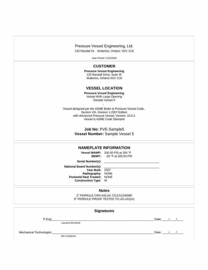
Pressure Vessel Engineering, Ltd.120 Randall Dr. Waterloo, Ontario N2V 1C6
Date Printed: 11/20/2008
CUSTOMERPressure Vessel Engineering
120 Randall Drive, Suite 'B'Waterloo, Ontario N2V 1C6
VESSEL LOCATIONPressure Vessel Engineering
Vessel With Large OpeningSample Vessel 5
,
Vessel designed per the ASME Boiler & Pressure Vessel Code,Section VIII, Division 1,2007 Edition
with Advanced Pressure Vessel, Version: 10.0.2Vessel is ASME Code Stamped
Job No: PVE-Samp le 5Vessel Number: Sample Vessel 5
NAMEPLATE INFORMATIONVessel MAWP: 200.00 PSI at 350 °F
MDMT: -20 °F at 200.00 PSI
Serial Number(s): __________________________________
National Board Number(s): __________________________________Year Built: 2007
Rad iography: NONEPostweld Heat Treated: NONE
Construction Type: W
Notes2" FERRULE CRN ASLOA 7213.51246089
8" FERRULE PROOF TESTED TO UG-101(m)
Signatures
P.Eng:_______________________________________________________________ Date: ____/____/____Laurence Brundrett
Mechanical Technologist:_______________________________________________________________ Date: ____/____/____Ben Vanderloo

Table of Contents
Outlet 8" Ferrule Nozzle D 1
Shell 2 - thin shell 2
thick shell 3
Conical Reducer 1 4
10" Inlet Nozzle C 5
2" Inlet Nozzle A 10
2"3000# Cplg N-E 13
2" Heavy Ferrule Nozzle B 16
10" Inlet Flange 19
Cover Flange 23
ASME Flanges 25
Cone to Cylinder 1 26
Cone to Cylinder 2 27
Cone to Cylinder 3 28
MDMT Summary 29
MAWP Summary 30
Summary Information 31

Pressure Vessel Engineering, Ltd.120 Randall Dr. Waterloo, Ontario N2V 1C6
Date Printed: 11/20/2008

Pressure Vessel Engineering, Ltd.Outlet 8" Ferrule Nozzle D
Cus tomer : Pressure Vessel EngineeringJob No: PVE-Sample5 Vessel Number: Sample Vessel 5
Number : 1 Mark Number: N-D
Date Printed: 11/20/2008
Cylindrical Shell Design Information
Design Pressure: 200.00 PSI Design Temperature: 350 °FStatic Head: 1.00 PSI Long. Joint Efficiency: 85 %
Shell Material: SA-479 304, High Factor B Chart: HA-1Material Stress (hot): 18600 PSI
Shell Length: 1.1020 in. Material Stress (cold): 20000 PSICompressive Stress: 9170 PSI
Corrosion Allowance: 0.0000 in. Actual Circumferential Stress: 12078 PSIExternal Corrosion Allowance: 0.0000 in. Actual Longitudinal Stress: 7189 PSI
Outside Diameter (new): 8.0300 in.Outside Diameter (corroded): 8.0300 in. Specific Gravity: 1.00
Shell Surface Area: 0.19 Sq. Ft. Weight of Fluid: 1.94 lb.Shell Estimated Volume: 0.23 Gal. Total Flooded Shell Weight: 2.56 lb.
Circ. Joint Efficiency: 70 % Shell Weight: 0.62 lb.
Minimum Design Metal Temperature Data
Minimum Design Metal Temperature: -20 °FMaterial exempt from impact testing per UCS-66(b), stress ratio <= 0.35
Design Thickness Calculations
Longitudinal Stress Calculations per Paragraph UG-27(c)(2)
t =PR
2SE + 0.4P=
201.00 * 3.93702 * 18600 * 0.70 + 0.4 * 201.00
= Greater Of (0.0303(Calculated), 0.0625(Minimum Allowed)) + 0.0000 (corros ion) + 0.0000 (ext. corrosion) = minimum of 0.0625 in .
Circumferential Stress Calculations per Appendix 1-1(a)(1)
t =PRo
SE + 0.4P=
201.00 * 4.015018600 * 0.85 + 0.4 * 201.00
= Greater of (0.0508(Calculated), 0.0625(Minimum Allowed)) + 0.0000 (corros ion) + 0.0000 (ext. corrosion) = minimum of 0.0625 in .
Extreme Fiber Elongation Calculation per Paragraph UHA-44
Elongation =50tRf
=50 * 0.0780
3.9760= elongation of 0.98 %
Nominal Shell Thickness Selected = 0.0780 in .
Advanced Pressure Vessel version: 10.0.2 ©Computer Engineering, Inc. Section VIII, Division 1, 2007 EditionPage 1 of 31

Pressure Vessel Engineering, Ltd.Shell 2 - thin shell
Cus tomer : Pressure Vessel EngineeringJob No: PVE-Sample5 Vessel Number: Sample Vessel 5
Number : 2 Mark Number: S2
Date Printed: 11/20/2008
Cylindrical Shell Design Information
Design Pressure: 200.00 PSI Design Temperature: 350 °FStatic Head: 1.00 PSI Long. Joint Efficiency: 70 %
Shell Material: SA-240 304, High Factor B Chart: HA-1Material Stress (hot): 18600 PSI
Shell Length: 15.5000 in. Material Stress (cold): 20000 PSICompressive Stress: 10102 PSI
Corrosion Allowance: 0.0000 in. Actual Circumferential Stress: 9622 PSIExternal Corrosion Allowance: 0.0000 in. Actual Longitudinal Stress: 4667 PSI
Outside Diameter (new): 12.7500 in.Outside Diameter (corroded): 12.7500 in. Specific Gravity: 1.00
Shell Surface Area: 4.31 Sq. Ft. Weight of Fluid: 67.42 lb.Shell Estimated Volume: 8.07 Gal. Total Flooded Shell Weight: 100.77 lb.
Circ. Joint Efficiency: 70 % Shell Weight: 33.35 lb.
Minimum Design Metal Temperature Data
Minimum Design Metal Temperature: -20 °FMaterial exempt from impact testing per UCS-66(b), stress ratio <= 0.35
Design Thickness Calculations
Longitudinal Stress Calculations per Paragraph UG-27(c)(2)
t =PR
2SE + 0.4P=
201.00 * 6.18702 * 18600 * 0.70 + 0.4 * 201.00
= Greater Of (0.0476(Calculated), 0.0625(Minimum Allowed)) + 0.0000 (corros ion) + 0.0000 (ext. corrosion) = minimum of 0.0625 in .
Circumferential Stress Calculations per Appendix 1-1(a)(1)
t =PRo
SE + 0.4P=
201.00 * 6.375018600 * 0.70 + 0.4 * 201.00
= 0.0979 + 0.0000 (corros ion) + 0.0000 (ext. corrosion) = minimum of 0.0979 in .
Extreme Fiber Elongation Calculation per Paragraph UHA-44
Elongation =50tRf
=50 * 0.1880
6.2810= elongation of 1.50 %
Nominal Shell Thickness Selected = 0.1880 in .
Advanced Pressure Vessel version: 10.0.2 ©Computer Engineering, Inc. Section VIII, Division 1, 2007 EditionPage 2 of 31

Pressure Vessel Engineering, Ltd.thick shell
Cus tomer : Pressure Vessel EngineeringJob No: PVE-Sample5 Vessel Number: Sample Vessel 5
Number : 3 Mark Number: S3
Date Printed: 11/20/2008
Cylindrical Shell Design Information
Design Pressure: 200.00 PSI Design Temperature: 350 °FStatic Head: 1.00 PSI Long. Joint Efficiency: 85 %
Shell Material: SA-312 TP304 SMLS, High Factor B Chart: HA-1Material Stress (hot): 18600 PSI
Shell Length: 4.5000 in. Material Stress (cold): 20000 PSICompressive Stress: 11376 PSI
Corrosion Allowance: 0.0000 in. Actual Circumferential Stress: 2413 PSIExternal Corrosion Allowance: 0.0000 in. Actual Longitudinal Stress: 1301 PSI
Outside Diameter (new): 12.7500 in.Outside Diameter (corroded): 12.7500 in. Specific Gravity: 1.00
Shell Surface Area: 1.25 Sq. Ft. Weight of Fluid: 16.54 lb.Shell Estimated Volume: 1.98 Gal. Total Flooded Shell Weight: 50.52 lb.
Circ. Joint Efficiency: 70 % Shell Weight: 33.98 lb.
Minimum Design Metal Temperature Data
Minimum Design Metal Temperature: -20 °FMaterial is exempt from impact testing per UHA-51(d)
Design Thickness Calculations
Longitudinal Stress Calculations per Paragraph UG-27(c)(2)
t =PR
2SE + 0.4P=
201.00 * 5.68802 * 18600 * 0.70 + 0.4 * 201.00
= Greater Of (0.0438(Calculated), 0.0625(Minimum Allowed)) + 0.0000 (corros ion) + 0.0000 (ext. corrosion) + 0.0859 (12 1/2% for pipe)= minimum of 0.1484 in .
Circumferential Stress Calculations per Appendix 1-1(a)(1)
t =PRo
SE + 0.4P=
201.00 * 6.375018600 * 0.85 + 0.4 * 201.00
= 0.0807 + 0.0000 (corros ion) + 0.0000 (ext. corrosion) + 0.0859 (12 1/2% for pipe)
= minimum of 0.1666 in .
Pipe Selected: Size = 12 in., Schedule = 80, Diameter = 12.7500 in., Wall = 0.6870 in .
Advanced Pressure Vessel version: 10.0.2 ©Computer Engineering, Inc. Section VIII, Division 1, 2007 EditionPage 3 of 31

Pressure Vessel Engineering, Ltd.Conical Reducer 1
Cus tomer : Pressure Vessel EngineeringJob No: PVE-Sample5 Vessel Number: Sample Vessel 5
Number : 1 Mark Number: R1
Date Printed: 11/20/2008
Conical Reducer Design Information
Design Pressure: 200.00 PSI Design Temperature: 350 °FStatic Head: 1.00 PSI Joint Efficiency: 70 %
Conical Reducer Material: SA-240 304, High Factor B Chart: HA-1Material Stress (hot): 18600 PSI
Corrosion Allowance: 0.0000 in. Material Stress (cold): 20000 PSIExternal Corrosion Allowance: 0.0000 in. Actual Conical Reducer Stress: 10681 PSISmall End of Cone Located at: Bottom Outside Ds : 8.0300 in.
Outside Diameter : 12.7500 in. Cone Height (h) : 4.9994 in.angle a ( ): 25.27
Conical Reducer Surface Area: 1.25 Sq. Ft. Specific Gravity: 1.00Conical Reducer Estimated Volume: 1.72 Gal. Weight of Fluid: 14.37 lb.
Conical Reducer Weight: 9.62 lb. Total Flooded Conical Reducer Weight: 23.99 lb.
Minimum Design Metal Temperature Data
Minimum Design Metal Temperature: -20 °FOther Exemption
Design Thickness Calculations
Design Thickness Calculations per Appendix 1-4(e)
t =PDo
2 cos (SE + 0.4P)=
201.00 * 12.75002 * 0.9043 * (18600 * 0.70 + 0.4 * 201.00 )
= 0.1082 + 0.0000 (corros ion ) + 0.0000 (ext. corrosion)
= minimum of 0.1082 in .
Extreme Fiber Elongation Calculation per Paragraph UHA-44
elongation =50tRf
=50 * 0.1875
3.9213= elongation of 2.39 %
Nominal Conical Reducer Thickness Selected = 0.1875 in .
Advanced Pressure Vessel version: 10.0.2 ©Computer Engineering, Inc. Section VIII, Division 1, 2007 EditionPage 4 of 31

Pressure Vessel Engineering, Ltd.10" Inlet Nozzle C
Cus tomer : Pressure Vessel EngineeringJob No: PVE-Sample5 Vessel Number: Sample Vessel 5
Number : 1 Mark Number: N-CID Number: N-C
Date Printed: 11/20/2008
Nozzle Design Information
Design Pressure: 200.00 PSI Design Temperature: 350 °FStatic Head: 1.00 PSI Nozzle Efficiency (E): 85 %
Nozzle Material: SA-312 TP304 SMLS, High Joint Efficiency (E1): 1.00Factor B Chart: HA-1
External Projection: 4.0000 in. Allowable Stress at Design Temperature (Sn): 18600 PSIInternal Projection: 0.0000 in. Allowable Stress at Ambient Temperature: 20000 PSI
Inside Corrosion Allowance: 0.0000 in. Correction Factor (F): 1.00External Corrosion Allowance: 0.0000 in. Nozzle Path: None
Nozzle Pipe Size: 10 Nozzle Pipe Schedule: 40Nozzle ID (new): 10.0200 in. Nozzle Wall Thickness(new): 0.3650 in.
Nozzle ID (corroded): 10.0200 in. Nozzle Wall Thickness(corroded): 0.3650 in.Outer "h" Limit: 0.4700 in. Upper Weld Leg Size(Weld 41): 0.2500 in.
Internal "h" Limit: 0.4700 in. Internal Weld Leg Size(Weld 43): 0.0000 in.OD, Limit of Reinforcement: 20.0400 in. Appendix 1-7 OD, Limit of Reinforcement(dLDR): 15.0300 in.
Outside Groove Weld Depth: 0.1880 in.
Minimum Design Metal Temperature
Minimum Design Metal Temperature: -20 °FMaterial exempt from impact testing per UCS-66(b), stress ratio <= 0.35
Host Component: Shell 2 - Shell 2 - thin shell
Material: SA-240 304, High Shell wall thickness(new): 0.1880 in.Material Stress(Sv): 18600 PSI Shell wall thickness(corroded): 0.1880 in.
Nozzle Detail Information
Upper Weld Leg Size(Weld 41): 0.2500 in.
Nozzle Wall Thickness(tn): 0.3650 in.
Outside Groove Weld Depth: 0.1880 in.
Nozzle passes through the vessel, attached by a groove weld.Pipe Size: 10 Schedule: 40
Nozzle is adequate for UG-45 requirements.Opening is adequately reinforced for Internal Pressure.
Large opening meets Appendix 1-7 stress calculation requirementsWeld Strength Paths are adequate.
Advanced Pressure Vessel version: 10.0.2 ©Computer Engineering, Inc. Section VIII, Division 1, 2007 EditionPage 5 of 31

Pressure Vessel Engineering, Ltd.10" Inlet Nozzle C
Job No: PVE-Sample5 Vessel Number: Sample Vessel 5Number : 1 Mark Number: N-C
ID Number: N-C
Date Printed: 11/20/2008
Required Shell Thickness per Paragraph UG-37(a)
tr =PRo
SE + 0.4P=
201.00 * 6.375018600 * 1 + 0.4 * 201.00
= 0.0686 in .
Nozzle Required Thickness Calculations
Required Nozzle Thickness for Internal Pressure per Paragraph UG-37(a)
trn =PRn
SE - 0.6P=
201.00 * 5.010018600 * 1 - 0.6 * 201.00
= 0.0545 in .
Strength Reduction Factors
fr1 = minSnSv
, 1.0000 = min1860018600
, 1.0000 = 1.0000 fr2 = minSnSv
, 1.0000 = min1860018600
, 1.0000 = 1.0000
fr3 = minSnSv
, 1.0000 = min1860018600
, 1.0000 = 1.0000
UG-45 Thickness Calculations
Nozzle Thickness for Pressure Loading (plus corrosion) per Paragraph UG-45(a)
t =PRn
SE - 0.6P+ Ca + ext. Ca =
201.00 * 5.010018600 * 0.85 - 0.6 * 201.00
+ 0.0000 + 0.0000 = 0.0642 in .
Nozzle Thickness for Internal Pressure (plus corrosion) per Paragraph UG-45(b)(1)
t =PRo
SE + 0.4P+ Ca + ext. Ca =
201.00 * 6.375018600 * 1 + 0.4 * 201.00
+ 0.0000 + 0.0000 = 0.0686 in .
Minimum Thickness of Standard Wall Pipe (plus corrosion) per Paragraph UG-45(b)(4)t = minimum thickness of standard wall pipe + Ca + ext. Ca = 0.3194 in .
Nozzle Minimum Thickness per Paragraph UG-45(b)t = Smallest of UG-45(b)(1) or UG-45(b)(4) = 0.0686 in .
Wall thickness = tn * 0.875(pipe) = 0.3194 is greater than or equal to UG-45 value of 0.0686
Advanced Pressure Vessel version: 10.0.2 ©Computer Engineering, Inc. Section VIII, Division 1, 2007 EditionPage 6 of 31
Pressure Vessel Engineering, Ltd.10" Inlet Nozzle C
Job No: PVE-Sample5 Vessel Number: Sample Vessel 5Number : 1 Mark Number: N-C
ID Number: N-C
Date Printed: 11/20/2008
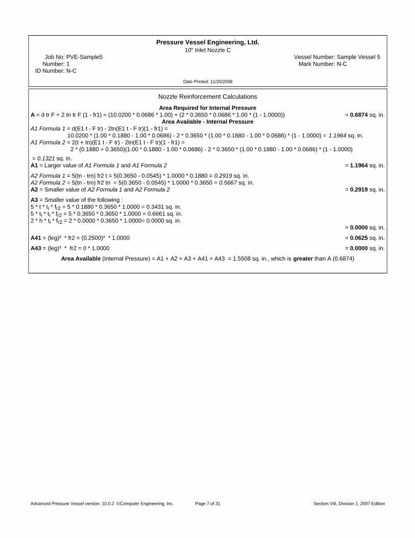
Nozzle Reinforcement Calculations
Area Required for Internal PressureA = d tr F + 2 tn tr F (1 - fr1) = (10.0200 * 0.0686 * 1.00) + (2 * 0.3650 * 0.0686 * 1.00 * (1 - 1.0000)) = 0.6874 sq. in.
Area Available - Internal PressureA1 Formula 1 = d(E1 t - F tr) - 2tn(E1 t - F tr)(1 - fr1) =
10.0200 * (1.00 * 0.1880 - 1.00 * 0.0686) - 2 * 0.3650 * (1.00 * 0.1880 - 1.00 * 0.0686) * (1 - 1.0000) = 1.1964 sq. in.A1 Formula 2 = 2(t + tn)(E1 t - F tr) - 2tn(E1 t - F tr)(1 - fr1) =
2 * (0.1880 + 0.3650)(1.00 * 0.1880 - 1.00 * 0.0686) - 2 * 0.3650 * (1.00 * 0.1880 - 1.00 * 0.0686) * (1 - 1.0000)= 0.1321 sq. in.
A1 = Larger value of A1 Formula 1 and A1 Formula 2 = 1.1964 sq. in.
A2 Formula 1 = 5(tn - trn) fr2 t = 5(0.3650 - 0.0545) * 1.0000 * 0.1880 = 0.2919 sq. in.A2 Formula 2 = 5(tn - trn) fr2 tn = 5(0.3650 - 0.0545) * 1.0000 * 0.3650 = 0.5667 sq. in.A2 = Smaller value of A2 Formula 1 and A2 Formula 2 = 0.2919 sq. in.
A3 = Smaller value of the following : 5 * t * ti * fr2 = 5 * 0.1880 * 0.3650 * 1.0000 = 0.3431 sq. in.5 * ti * ti * fr2 = 5 * 0.3650 * 0.3650 * 1.0000 = 0.6661 sq. in.2 * h * ti * fr2 = 2 * 0.0000 * 0.3650 * 1.0000= 0.0000 sq. in.
= 0.0000 sq. in.
A41 = (leg) * fr2 = (0.2500) * 1.0000 = 0.0625 sq. in.
A43 = (leg) * fr2 = 0 * 1.0000 = 0.0000 sq. in.
Area Available (Internal Pressure) = A1 + A2 + A3 + A41 + A43 = 1.5508 sq. in., which is greater than A (0.6874)
Advanced Pressure Vessel version: 10.0.2 ©Computer Engineering, Inc. Section VIII, Division 1, 2007 EditionPage 7 of 31
Pressure Vessel Engineering, Ltd.10" Inlet Nozzle C
Job No: PVE-Sample5 Vessel Number: Sample Vessel 5Number : 1 Mark Number: N-C
ID Number: N-C
Date Printed: 11/20/2008
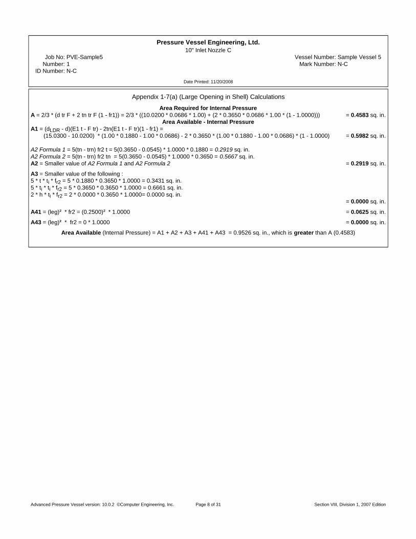
Appendix 1-7(a) (Large Opening in Shell) Calculations
Area Required for Internal PressureA = 2/3 * (d tr F + 2 tn tr F (1 - fr1)) = 2/3 * ((10.0200 * 0.0686 * 1.00) + (2 * 0.3650 * 0.0686 * 1.00 * (1 - 1.0000))) = 0.4583 sq. in.
Area Available - Internal PressureA1 = (dLDR - d)(E1 t - F tr) - 2tn(E1 t - F tr)(1 - fr1) = (15.0300 - 10.0200) * (1.00 * 0.1880 - 1.00 * 0.0686) - 2 * 0.3650 * (1.00 * 0.1880 - 1.00 * 0.0686) * (1 - 1.0000) = 0.5982 sq. in.
A2 Formula 1 = 5(tn - trn) fr2 t = 5(0.3650 - 0.0545) * 1.0000 * 0.1880 = 0.2919 sq. in.A2 Formula 2 = 5(tn - trn) fr2 tn = 5(0.3650 - 0.0545) * 1.0000 * 0.3650 = 0.5667 sq. in.A2 = Smaller value of A2 Formula 1 and A2 Formula 2 = 0.2919 sq. in.
A3 = Smaller value of the following : 5 * t * ti * fr2 = 5 * 0.1880 * 0.3650 * 1.0000 = 0.3431 sq. in.5 * ti * ti * fr2 = 5 * 0.3650 * 0.3650 * 1.0000 = 0.6661 sq. in.2 * h * ti * fr2 = 2 * 0.0000 * 0.3650 * 1.0000= 0.0000 sq. in.
= 0.0000 sq. in.
A41 = (leg) * fr2 = (0.2500) * 1.0000 = 0.0625 sq. in.
A43 = (leg) * fr2 = 0 * 1.0000 = 0.0000 sq. in.
Area Available (Internal Pressure) = A1 + A2 + A3 + A41 + A43 = 0.9526 sq. in., which is greater than A (0.4583)
Advanced Pressure Vessel version: 10.0.2 ©Computer Engineering, Inc. Section VIII, Division 1, 2007 EditionPage 8 of 31

Pressure Vessel Engineering, Ltd.10" Inlet Nozzle C
Job No: PVE-Sample5 Vessel Number: Sample Vessel 5Number : 1 Mark Number: N-C
ID Number: N-C
Date Printed: 11/20/2008
Nozzle Weld Strength Calculations
Attachment Weld Strength per Paragraph UW-16
Weld 41 tmin = smaller of 0.75, t, or tn = smaller of 0.75, 0.1880, or 0.3650 = 0.1880 in .
Weld 41 Leg min. =(smaller of 0.25 or (tmin * 0.7)) + ext. CA
0.7=
0.13160.7
= 0.1880 in .
Weld 41, actual weld leg = 0.2500 in .
Unit Stresses per Paragraphs UG-45(c) and UW-15Nozzle wall in shear = 0.70 * Sn = 0.70 * 18600 = 13020 PS IUpper fillet, Weld 41, in shear = 0.49 * Material Stress = 0.49 * 18600 = 9114 PS IVessel groove weld, in tension = 0.74 * Material Stress = 0.74 * 18600 = 13764 PS I
Strength of Connection ElementsNozzle wall in shear = * * mean nozzle diameter * tn * Nozzle wall in shear unit stress =
* * 10.3850 * 0.3650 * 13020 = 77500 lb .Upper fillet in shear = * * Nozzle OD * weld leg * upper fillet in shear unit stress = * * 10.7500 * 0.2500 * 9114 = 38500 lb .Groove Weld in Tension = * * Nozzle OD * groove depth * groove weld tension unit stress =
* * 10.7500 * 0.1880 * 13764 = 43700 lb .
Load to be carried by welds, per UG-41(b)(1) and Fig. UG-41.1 sketch (a)W = [A - A1 + 2 tn fr1(E1t - Ftr)] Sv = [0.6874 - 1.1964 + 2 * 0.3650 * 1.0000 * (1.00 * 0.1880 - 1.0000 * 0.0686)] * 18600 = -7846 lb .W1-1 = (A2 + A5 + A41 + A42) * Sv = (0.2919 + 0.0000 + 0.0625 + 0.0000) * 18600 = 6590 lb .W2-2 = (A2 + A3 + A41 + A43 + 2 tn t fr1) Sv = (0.2919 + 0.0000 + 0.0625 + 0.0000 + 2 * 0.3650 * 0.1880 * 1.0000) * 18600 = 9140 lb .W3-3 = (A2 + A3 + A5 + A41 + A42 + A43 + 2 tn t fr1) * Sv = (0.2919 + 0.0000 + 0.0000 + 0.0625 + 0.0000 + 0.0000 + 2 * 0.3650 * 0.1880 * 1.0000) * 18600 = 9140 lb .
Check Strength PathsPath 1-1 = Upper fillet in shear + Nozzle wall in shear = 38500 + 77500 = 116000 lb .Path 2-2 = Upper fillet in shear + Groove weld in tension + Inner fillet in shear =
38500 + 43700 + 0 = 82200 lb .Path 3-3 = Upper fillet in shear + Inner fillet in shear + Groove weld in tension = 38500 + 0 + 43700 = 82200 lb .
Advanced Pressure Vessel version: 10.0.2 ©Computer Engineering, Inc. Section VIII, Division 1, 2007 EditionPage 9 of 31

Pressure Vessel Engineering, Ltd.2" Inlet Nozzle A
Cus tomer : Pressure Vessel EngineeringJob No: PVE-Sample5 Vessel Number: Sample Vessel 5
Number : 2 Mark Number: N-AID Number: N-A
Date Printed: 11/20/2008
Nozzle Design Information
Design Pressure: 200.00 PSI Design Temperature: 350 °FStatic Head: 1.00 PSI Nozzle Efficiency (E): 85 %
Nozzle Material: SA-312 TP304 SMLS, High Joint Efficiency (E1): 1.00Factor B Chart: HA-1
External Projection: 3.0000 in. Allowable Stress at Design Temperature (Sn): 18600 PSIInternal Projection: 0.0000 in. Allowable Stress at Ambient Temperature: 20000 PSI
Inside Corrosion Allowance: 0.0000 in. Correction Factor (F): 1.00External Corrosion Allowance: 0.0000 in. Nozzle Path: None
Nozzle Pipe Size: 2 Nozzle Pipe Schedule: 40Nozzle ID (new): 2.0670 in. Nozzle Wall Thickness(new): 0.1540 in.
Nozzle ID (corroded): 2.0670 in. Nozzle Wall Thickness(corroded): 0.1540 in.Developed Opening: 2.1920 in. Tangential Dimension L: 7.0000 in.
Outer "h" Limit: 0.3850 in. Upper Weld Leg Size(Weld 41): 0.1880 in.Internal "h" Limit: 0.3850 in. Internal Weld Leg Size(Weld 43): 0.0000 in.
OD, Limit of Reinforcement: 4.3840 in. Outside Groove Weld Depth: 0.1875 in.
Minimum Design Metal Temperature
Minimum Design Metal Temperature: -20 °FMaterial exempt from impact testing per UCS-66(b), stress ratio <= 0.35
Host Component: Cone 1 - Conical Reducer 1
Material: SA-240 304, High Conical Reducer wall thickness(new): 0.1875 in.Material Stress(Sv): 18600 PSIonical Reducer wall thickness - thin out (corroded): 0.1875 in.
Distance from small end of cone: 2.5000 in. Diameter of Cone at Nozzle: 10.3903 in.
Nozzle Detail Information
Upper Weld Leg Size(Weld 41): 0.1880 in.
Nozzle Wall Thickness(tn): 0.1540 in.
Outside Groove Weld Depth: 0.1875 in.
tangential to the vessel wall, attached by a groove weld.Pipe Size: 2 Schedule: 40
Nozzle is adequate for UG-45 requirements.Opening is adequately reinforced for Internal Pressure.
Reinforcement calculations are not required per UG-36(c)(3)(a)See Uw-14 for exceptions.Weld Strength Paths are adequate.
Advanced Pressure Vessel version: 10.0.2 ©Computer Engineering, Inc. Section VIII, Division 1, 2007 EditionPage 10 of 31

Pressure Vessel Engineering, Ltd.2" Inlet Nozzle A
Job No: PVE-Sample5 Vessel Number: Sample Vessel 5Number : 2 Mark Number: N-A
ID Number: N-A
Date Printed: 11/20/2008
Required Conical Reducer Thickness per Paragraph UG-37(a)
tr =PDo
(2 * cos (SE + 0.4P))=
201.00 * 10.3903(2 * 0.9043 * (18600 * 1 + 0.4 * 201.00))
= 0.0618 in .
Nozzle Required Thickness Calculations
Required Nozzle Thickness for Internal Pressure per Paragraph UG-37(a)
trn =PRn
SE - 0.6P=
201.00 * 1.033518600 * 1 - 0.6 * 201.00
= 0.0112 in .
Strength Reduction Factors
fr1 = minSnSv
, 1.0000 = min1860018600
, 1.0000 = 1.0000 fr2 = minSnSv
, 1.0000 = min1860018600
, 1.0000 = 1.0000
fr3 = minSnSv
, 1.0000 = min1860018600
, 1.0000 = 1.0000
UG-45 Thickness Calculations
Nozzle Thickness for Pressure Loading (plus corrosion) per Paragraph UG-45(a)
t =PRn
SE - 0.6P+ Ca + ext. Ca =
201.00 * 1.033518600 * 0.85 - 0.6 * 201.00
+ 0.0000 + 0.0000 = 0.0132 in .
Nozzle Thickness for Internal Pressure (plus corrosion) per Paragraph UG-45(b)(1)
t =PDo
(2 * cos (SE + 0.4P))+ Ca + ext. Ca =
201.00 * 10.3903(2 * 0.9043 * (18600 * 1 + 0.4 * 201.00))
+ 0.0000 + 0.0000
= Greater Of (0.0618(Calculated), 0.0625(Minimum Allowed)) + 0.0000 (corros ion) + 0.0000 (ext. corrosion) = 0.0625 in .
Minimum Thickness of Standard Wall Pipe (plus corrosion) per Paragraph UG-45(b)(4)t = minimum thickness of standard wall pipe + Ca + ext. Ca = 0.1347 in .
Nozzle Minimum Thickness per Paragraph UG-45(b)t = Smallest of UG-45(b)(1) or UG-45(b)(4) = 0.0625 in .
Wall thickness = tn * 0.875(pipe) = 0.1347 is greater than or equal to UG-45 value of 0.0625
Advanced Pressure Vessel version: 10.0.2 ©Computer Engineering, Inc. Section VIII, Division 1, 2007 EditionPage 11 of 31
Pressure Vessel Engineering, Ltd.2" Inlet Nozzle A
Job No: PVE-Sample5 Vessel Number: Sample Vessel 5Number : 2 Mark Number: N-A
ID Number: N-A
Date Printed: 11/20/2008
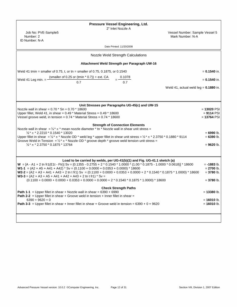
Nozzle Weld Strength Calculations
Attachment Weld Strength per Paragraph UW-16
Weld 41 tmin = smaller of 0.75, t, or tn = smaller of 0.75, 0.1875, or 0.1540 = 0.1540 in .
Weld 41 Leg min. =(smaller of 0.25 or (tmin * 0.7)) + ext. CA
0.7=
0.10780.7
= 0.1540 in .
Weld 41, actual weld leg = 0.1880 in .
Unit Stresses per Paragraphs UG-45(c) and UW-15Nozzle wall in shear = 0.70 * Sn = 0.70 * 18600 = 13020 PS IUpper fillet, Weld 41, in shear = 0.49 * Material Stress = 0.49 * 18600 = 9114 PS IVessel groove weld, in tension = 0.74 * Material Stress = 0.74 * 18600 = 13764 PS I
Strength of Connection ElementsNozzle wall in shear = * * mean nozzle diameter * tn * Nozzle wall in shear unit stress =
* * 2.2210 * 0.1540 * 13020 = 6990 lb .Upper fillet in shear = * * Nozzle OD * weld leg * upper fillet in shear unit stress = * * 2.3750 * 0.1880 * 9114 = 6390 lb .Groove Weld in Tension = * * Nozzle OD * groove depth * groove weld tension unit stress =
* * 2.3750 * 0.1875 * 13764 = 9620 lb .
Load to be carried by welds, per UG-41(b)(1) and Fig. UG-41.1 sketch (a)W = [A - A1 + 2 tn fr1(E1t - Ftr)] Sv = [0.1355 - 0.2755 + 2 * 0.1540 * 1.0000 * (1.00 * 0.1875 - 1.0000 * 0.0618)] * 18600 = -1883 lb .W1-1 = (A2 + A5 + A41 + A42) * Sv = (0.1100 + 0.0000 + 0.0353 + 0.0000) * 18600 = 2700 lb .W2-2 = (A2 + A3 + A41 + A43 + 2 tn t fr1) Sv = (0.1100 + 0.0000 + 0.0353 + 0.0000 + 2 * 0.1540 * 0.1875 * 1.0000) * 18600 = 3780 lb .W3-3 = (A2 + A3 + A5 + A41 + A42 + A43 + 2 tn t fr1) * Sv = (0.1100 + 0.0000 + 0.0000 + 0.0353 + 0.0000 + 0.0000 + 2 * 0.1540 * 0.1875 * 1.0000) * 18600 = 3780 lb .
Check Strength PathsPath 1-1 = Upper fillet in shear + Nozzle wall in shear = 6390 + 6990 = 13380 lb .Path 2-2 = Upper fillet in shear + Groove weld in tension + Inner fillet in shear =
6390 + 9620 + 0 = 16010 lb .Path 3-3 = Upper fillet in shear + Inner fillet in shear + Groove weld in tension = 6390 + 0 + 9620 = 16010 lb .
Advanced Pressure Vessel version: 10.0.2 ©Computer Engineering, Inc. Section VIII, Division 1, 2007 EditionPage 12 of 31

Pressure Vessel Engineering, Ltd.2"3000# Cplg N-E
Cus tomer : Pressure Vessel EngineeringJob No: PVE-Sample5 Vessel Number: Sample Vessel 5
Number : 3 Mark Number: N-EID Number: N-E
Date Printed: 11/20/2008
Nozzle Design Information
Design Pressure: 200.00 PSI Design Temperature: 350 °FStatic Head: 0.00 PSI Nozzle Efficiency (E): 70 %
Nozzle Material: SA-182 F304 <=5", High Joint Efficiency (E1): 1.00Factor B Chart: HA-1
External Projection: 1.0000 in. Allowable Stress at Design Temperature (Sn): 18600 PSIAllowable Stress at Ambient Temperature: 20000 PSI
Inside Corrosion Allowance: 0.0000 in. Correction Factor (F): 1.00External Corrosion Allowance: 0.0000 in. Nozzle Path: None
Nozzle ID (new): 2.0970 in. Nozzle Wall Thickness(new): 0.2730 in.Nozzle ID (corroded): 2.0970 in. Nozzle Wall Thickness(corroded): 0.2730 in.
Outer "h" Limit: 0.6825 in. Upper Weld Leg Size(Weld 41): 0.3130 in.OD, Limit of Reinforcement: 4.6430 in. Outside Groove Weld Depth: 0.2730 in.
Minimum Design Metal Temperature
Minimum Design Metal Temperature: -20 °FMaterial exempt from impact testing per UCS-66(b), stress ratio <= 0.35
Host Component: Flange 2 - Cover Flange
Material: SA-240 304, Low Host Flange wall thickness(new): 1.0000 in.Material Stress(Sv): 14400 PSI Host Flange wall thickness(corroded): 1.0000 in.
Nozzle Detail Information
Upper Weld Leg Size(Weld 41): 0.3130 in.
Nozzle Wall Thickness(tn): 0.2730 in.
Outside Groove Weld Depth: 0.2730 in.
Nozzle abuts the vessel, attached by a groove weld.Nozzle is adequate for UG-45 requirements.
Opening is adequately reinforced for Internal Pressure.Reinforcement calculations are not required per UG-36(c)(3)(a)See Uw-14 for exceptions.
Weld Strength Paths are adequate.
Advanced Pressure Vessel version: 10.0.2 ©Computer Engineering, Inc. Section VIII, Division 1, 2007 EditionPage 13 of 31

Pressure Vessel Engineering, Ltd.2"3000# Cplg N-E
Job No: PVE-Sample5 Vessel Number: Sample Vessel 5Number : 3 Mark Number: N-E
ID Number: N-E
Date Printed: 11/20/2008
Required Host Flange Thickness per Paragraph UG-39(b)(1)
tr = G *CPSE
+1.9 Wm1 hG
SE G= 12.4800 *
0.3000 * 200.0014400 * 1
+1.9 * 25923 * 1.135014400 * 1 * 12.4800
= 0.9798 in .
Nozzle Required Thickness Calculations
Required Nozzle Thickness for Internal Pressure per Paragraph UG-37(a)
trn =PRn
SE - 0.6P=
200.00 * 1.048518600 * 1 - 0.6 * 200.00
= 0.0113 in .
Strength Reduction Factors
fr2 = minSnSv
, 1.0000 = min1860014400
, 1.0000 = 1.0000 fr3 = minSnSv
, 1.0000 = min1860014400
, 1.0000 = 1.0000
UG-45 Thickness Calculations
Nozzle Thickness for Pressure Loading (plus corrosion) per Paragraph UG-45(a)
t =PRn
SE - 0.6P+ Ca + ext. Ca =
200.00 * 1.048518600 * 0.70 - 0.6 * 200.00
+ 0.0000 + 0.0000 = 0.0163 in .
Nozzle Thickness for Internal Pressure (plus corrosion) per Paragraph UG-45(b)(1)
t = G *CPSE
+1.9 Wm1 hG
SE G+ Ca + ext. Ca = 12.4800 *
0.3000 * 200.0014400 * 1
+1.9 * 25923 * 1.135014400 * 1 * 12.4800
+ 0.0000 + 0.0000
= = 0.9798 in .
Minimum Thickness of Standard Wall Pipe (plus corrosion) per Paragraph UG-45(b)(4)t = minimum thickness of standard wall pipe + Ca + ext. Ca = 0.1776 in .
Nozzle Minimum Thickness per Paragraph UG-45(b)t = Smallest of UG-45(b)(1) or UG-45(b)(4) = 0.1776 in .
Wall thickness = tn = 0.2730 is greater than or equal to UG-45 value of 0.1776
Advanced Pressure Vessel version: 10.0.2 ©Computer Engineering, Inc. Section VIII, Division 1, 2007 EditionPage 14 of 31

Pressure Vessel Engineering, Ltd.2"3000# Cplg N-E
Job No: PVE-Sample5 Vessel Number: Sample Vessel 5Number : 3 Mark Number: N-E
ID Number: N-E
Date Printed: 11/20/2008
Nozzle Weld Strength Calculations
Attachment Weld Strength per Paragraph UW-16
Weld 41 tmin = smaller of 0.75, t, or tn = smaller of 0.75, 1.0000, or 0.2730 = 0.2730 in .
Weld 41 Leg min. =(smaller of 0.25 or (tmin * 0.7)) + ext. CA
0.7=
0.19110.7
= 0.2730 in .
Weld 41, actual weld leg = 0.3130 in .
Unit Stresses per Paragraphs UG-45(c) and UW-15Groove weld in shear = 0.60 * Groove Material Stress = 0.60 * 14400 = 8640 PS IUpper fillet, Weld 41, in shear = 0.49 * Material Stress = 0.49 * 14400 = 7056 PS I
Strength of Connection ElementsGroove weld in shear = * * mean nozzle diameter * tn * Groove weld in shear unit stress =
* * 2.3700 * 0.2730 * 8640 = 8780 lb .Upper fillet in shear = * * Nozzle OD * weld leg * upper fillet in shear unit stress = * * 2.6430 * 0.3130 * 7056 = 9160 lb .
Load to be carried by welds, per UG-41(b)(1) and Fig. UG-41.1 sketch (b)W = (A - A1) Sv = (1.0273 - 0.0514) * 14400 = 14100 lb .W1-1 = (A2 + A5 + A41 + A42) * Sv = (0.3572 + 0.0000 + 0.0980 + 0.0000) * 14400 = 6550 lb .W2-2 = (A2 + A41) Sv = (0.3572 + 0.0980) * 14400 = 6550 lb .
Check Strength PathsPath 1-1 = Upper fillet in shear + Groove weld in shear = 9160 + 8780 = 17940 lb .Path 2-2 = Upper fillet in shear + Groove weld in shear =
9160 + 8780 = 17940 lb .
Advanced Pressure Vessel version: 10.0.2 ©Computer Engineering, Inc. Section VIII, Division 1, 2007 EditionPage 15 of 31

Pressure Vessel Engineering, Ltd.2" Heavy Ferrule Nozzle B
Cus tomer : Pressure Vessel EngineeringJob No: PVE-Sample5 Vessel Number: Sample Vessel 5
Number : 4 Mark Number: N-BID Number: N-B
Date Printed: 11/20/2008
Nozzle Design Information
Design Pressure: 200.00 PSI Design Temperature: 350 °FStatic Head: 0.00 PSI Nozzle Efficiency (E): 70 %
Nozzle Material: SA-479 304, High Joint Efficiency (E1): 1.00Factor B Chart: HA-1
External Projection: 1.5000 in. Allowable Stress at Design Temperature (Sn): 18600 PSIInternal Projection: 0.0000 in. Allowable Stress at Ambient Temperature: 20000 PSI
Inside Corrosion Allowance: 0.0000 in. Correction Factor (F): 1.00External Corrosion Allowance: 0.0000 in. Nozzle Path: None
Nozzle ID (new): 1.8700 in. Nozzle Wall Thickness(new): 0.1610 in.Nozzle ID (corroded): 1.8700 in. Nozzle Wall Thickness(corroded): 0.1610 in.
Outer "h" Limit: 0.4025 in. Upper Weld Leg Size(Weld 41): 0.1880 in.Internal "h" Limit: 0.4025 in. Internal Weld Leg Size(Weld 43): 0.0000 in.
OD, Limit of Reinforcement: 3.7400 in. Outside Groove Weld Depth: 0.1880 in.
Minimum Design Metal Temperature
Minimum Design Metal Temperature: -20 °FMaterial exempt from impact testing per UCS-66(b), stress ratio <= 0.35
Host Component: Shell 2 - Shell 2 - thin shell
Material: SA-240 304, High Shell wall thickness(new): 0.1880 in.Material Stress(Sv): 18600 PSI Shell wall thickness(corroded): 0.1880 in.
Nozzle Detail Information
Upper Weld Leg Size(Weld 41): 0.1880 in.
Nozzle Wall Thickness(tn): 0.1610 in.
Outside Groove Weld Depth: 0.1880 in.
Nozzle passes through the vessel, attached by a groove weld.Nozzle is adequate for UG-45 requirements.
Opening is adequately reinforced for Internal Pressure.Reinforcement calculations are not required per UG-36(c)(3)(a)See Uw-14 for exceptions.
Weld Strength Paths are adequate.
Advanced Pressure Vessel version: 10.0.2 ©Computer Engineering, Inc. Section VIII, Division 1, 2007 EditionPage 16 of 31
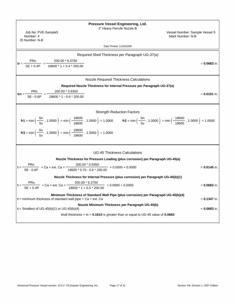
Pressure Vessel Engineering, Ltd.2" Heavy Ferrule Nozzle B
Job No: PVE-Sample5 Vessel Number: Sample Vessel 5Number : 4 Mark Number: N-B
ID Number: N-B
Date Printed: 11/20/2008
Required Shell Thickness per Paragraph UG-37(a)
tr =PRo
SE + 0.4P=
200.00 * 6.375018600 * 1 + 0.4 * 200.00
= 0.0683 in .
Nozzle Required Thickness Calculations
Required Nozzle Thickness for Internal Pressure per Paragraph UG-37(a)
trn =PRn
SE - 0.6P=
200.00 * 0.935018600 * 1 - 0.6 * 200.00
= 0.0101 in .
Strength Reduction Factors
fr1 = minSnSv
, 1.0000 = min1860018600
, 1.0000 = 1.0000 fr2 = minSnSv
, 1.0000 = min1860018600
, 1.0000 = 1.0000
fr3 = minSnSv
, 1.0000 = min1860018600
, 1.0000 = 1.0000
UG-45 Thickness Calculations
Nozzle Thickness for Pressure Loading (plus corrosion) per Paragraph UG-45(a)
t =PRn
SE - 0.6P+ Ca + ext. Ca =
200.00 * 0.935018600 * 0.70 - 0.6 * 200.00
+ 0.0000 + 0.0000 = 0.0145 in .
Nozzle Thickness for Internal Pressure (plus corrosion) per Paragraph UG-45(b)(1)
t =PRo
SE + 0.4P+ Ca + ext. Ca =
200.00 * 6.375018600 * 1 + 0.4 * 200.00
+ 0.0000 + 0.0000 = 0.0683 in .
Minimum Thickness of Standard Wall Pipe (plus corrosion) per Paragraph UG-45(b)(4)t = minimum thickness of standard wall pipe + Ca + ext. Ca = 0.1347 in .
Nozzle Minimum Thickness per Paragraph UG-45(b)t = Smallest of UG-45(b)(1) or UG-45(b)(4) = 0.0683 in .
Wall thickness = tn = 0.1610 is greater than or equal to UG-45 value of 0.0683
Advanced Pressure Vessel version: 10.0.2 ©Computer Engineering, Inc. Section VIII, Division 1, 2007 EditionPage 17 of 31

Pressure Vessel Engineering, Ltd.2" Heavy Ferrule Nozzle B
Job No: PVE-Sample5 Vessel Number: Sample Vessel 5Number : 4 Mark Number: N-B
ID Number: N-B
Date Printed: 11/20/2008
Nozzle Weld Strength Calculations
Attachment Weld Strength per Paragraph UW-16
Weld 41 tmin = smaller of 0.75, t, or tn = smaller of 0.75, 0.1880, or 0.1610 = 0.1610 in .
Weld 41 Leg min. =(smaller of 0.25 or (tmin * 0.7)) + ext. CA
0.7=
0.11270.7
= 0.1610 in .
Weld 41, actual weld leg = 0.1880 in .
Unit Stresses per Paragraphs UG-45(c) and UW-15Nozzle wall in shear = 0.70 * Sn = 0.70 * 18600 = 13020 PS IUpper fillet, Weld 41, in shear = 0.49 * Material Stress = 0.49 * 18600 = 9114 PS IVessel groove weld, in tension = 0.74 * Material Stress = 0.74 * 18600 = 13764 PS I
Strength of Connection ElementsNozzle wall in shear = * * mean nozzle diameter * tn * Nozzle wall in shear unit stress =
* * 2.0310 * 0.1610 * 13020 = 6680 lb .Upper fillet in shear = * * Nozzle OD * weld leg * upper fillet in shear unit stress = * * 2.1920 * 0.1880 * 9114 = 5900 lb .Groove Weld in Tension = * * Nozzle OD * groove depth * groove weld tension unit stress =
* * 2.1920 * 0.1880 * 13764 = 8910 lb .
Load to be carried by welds, per UG-41(b)(1) and Fig. UG-41.1 sketch (a)W = [A - A1 + 2 tn fr1(E1t - Ftr)] Sv = [0.1277 - 0.2238 + 2 * 0.1610 * 1.0000 * (1.00 * 0.1880 - 1.0000 * 0.0683)] * 18600 = -1070 lb .W1-1 = (A2 + A5 + A41 + A42) * Sv = (0.1215 + 0.0000 + 0.0353 + 0.0000) * 18600 = 2920 lb .W2-2 = (A2 + A3 + A41 + A43 + 2 tn t fr1) Sv = (0.1215 + 0.0000 + 0.0353 + 0.0000 + 2 * 0.1610 * 0.1880 * 1.0000) * 18600 = 4040 lb .W3-3 = (A2 + A3 + A5 + A41 + A42 + A43 + 2 tn t fr1) * Sv = (0.1215 + 0.0000 + 0.0000 + 0.0353 + 0.0000 + 0.0000 + 2 * 0.1610 * 0.1880 * 1.0000) * 18600 = 4040 lb .
Check Strength PathsPath 1-1 = Upper fillet in shear + Nozzle wall in shear = 5900 + 6680 = 12580 lb .Path 2-2 = Upper fillet in shear + Groove weld in tension + Inner fillet in shear =
5900 + 8910 + 0 = 14810 lb .Path 3-3 = Upper fillet in shear + Inner fillet in shear + Groove weld in tension = 5900 + 0 + 8910 = 14810 lb .
Advanced Pressure Vessel version: 10.0.2 ©Computer Engineering, Inc. Section VIII, Division 1, 2007 EditionPage 18 of 31
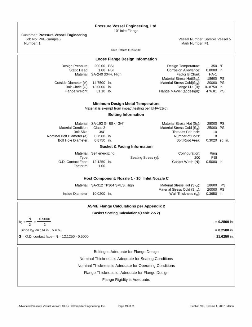
Pressure Vessel Engineering, Ltd.10" Inlet Flange
Cus tomer : Pressure Vessel EngineeringJob No: PVE-Sample5 Vessel Number: Sample Vessel 5
Number : 1 Mark Number: F1
Date Printed: 11/20/2008
Loose Flange Design Information
Design Pressure: 200.00 PSI Design Temperature: 350 °FStatic Head: 1.00 PSI Corrosion Allowance: 0.0000 in.
Material: SA-240 304H, High Factor B Chart: HA-1Material Stress Hot(Sfo): 18600 PSI
Outside Diameter (A): 14.7500 in. Material Stress Cold(Sfa): 20000 PSIBolt Circle (C): 13.0000 in. Flange I.D. (B): 10.8750 in.
Flange Weight: 31.10 lb. Flange MAWP (at design): 476.81 PSI
Minimum Design Metal TemperatureMaterial is exempt from impact testing per UHA-51(d)
Bolting Information
Material: SA-193 Gr B8 <=3/4" Material Stress Hot (Sb): 25000 PSIMaterial Condition: Class 2 Material Stress Cold (Sa): 25000 PSI
Bolt Size: 3/4" Threads Per Inch: 10Nominal Bolt Diameter (a): 0.7500 in. Number of Bolts: 8
Bolt Hole Diameter: 0.8750 in. Bolt Root Area: 0.3020 sq. in.
Gasket & Facing Information
Material: Self energizing Configuration: RingType: Seating Stress (y): 200 PS I
O.D. Contact Face: 12.1250 in. Gasket Width (N): 0.5000 in.Factor m: 1.00
Host Component: Nozzle 1 - 10" Inlet Nozzle C
Material: SA-312 TP304 SMLS, High Material Stress Hot (Sno): 18600 PS IMaterial Stress Cold (Sna): 20000 PSI
Inside Diameter: 10.0200 in. Wall Thickness (tn): 0.3650 in.
ASME Flange Calculations per Appendix 2
Gasket Seating Calculations(Table 2-5.2)
b0 =N2
=0.5000
2= 0.2500 in .
Since b0 <= 1/4 in., b = b0 = 0.2500 in .
G = O.D. contact face - N = 12.1250 - 0.5000 = 11 .6250 in.
Bolting is Adequate for Flange Design
Nominal Thickness is Adequate for Seating Conditions
Nominal Thickness is Adequate for Operating Conditions
Flange Thickness is Adequate for Flange Design
Flange Rigidity is Adequate.
Advanced Pressure Vessel version: 10.0.2 ©Computer Engineering, Inc. Section VIII, Division 1, 2007 EditionPage 19 of 31

Pressure Vessel Engineering, Ltd.10" Inlet Flange
Job No: PVE-Sample5 Vessel Number: Sample Vessel 5Number : 1 Mark Number: F1
Date Printed: 11/20/2008
Load and Bolting Calculations - Internal Pressure
The absolute value of effective pressure “P” is used for calculations.
P =16 M
G+
4 FAG
+ Pint + Static Head =16 * 0
3.14159 * 11.6250+
4 * 03.14159 * 11.6250
+ 200.00 + 1.00 = 201.00 PS I
Minimum Wm2 = bGy = 3.14159 * 0.2500 * 11.6250 * 200 = 1826 lb .
H =4
G P =3.14159
4* 11.6250 * 201.00 = 21334 lb .
Hp = 2b GmP = 2 * 0.2500 * 3.14159 * 11.6250 * 1.00 * 201.00 = 3670 lb.
Minimum Wm1 = H + Hp = 21334 + 3670 = 25004 lb .
Am1 =Wm1Sb
=4117325000
= 1.6469 sq. in.
Am2 =Wm2Sa
=1826
25000= 0.0730 sq. in.
Am = Greater of Am1 or Am2 = greater of 1.6469 or 0.0730 = 1.6469 sq. in.
Ab = Number of Bolts * Bolt Root Area = 8 * 0.3020 = 2.4160 sq. in.
W =(Am+ Ab)Sa
2=
(1.6469 + 2.4160) * 250002
= 50786 lb .
Ab >= Am, Bolting is Adequate for Flange Design
Internal Pressure Moment Calculations - Operating Conditions
HD =4
B P =3.1416
4* 10.8750 * 201.00 = 18670 lb .
HG = Wm1 - H = 41173 - 21334 = 19839 lb.
HT = H - HD = 21334 - 18670 = 2664 lb.
hD =C - B
2=
13.0000 - 10.87502
= 1 .0625 in.
hG =C - G
2=
13.0000 - 11.62502
= 0 .6875 in.
hT =hD + hG
2=
1.0625 + 0.68752
= 0 .8750 in.
MD = HDhD = 18670 * 1.0625 = 19837 in.-lb.
MG = HGh"G = 19839 * 0.6875 = 13639 in.-lb.
MT = HThT = 2664 * 0.8750 = 2331 in.-lb.
Mo = MD + MG + MT = 19837 + 13639 + 2331 = 35807 in.-lb.
Advanced Pressure Vessel version: 10.0.2 ©Computer Engineering, Inc. Section VIII, Division 1, 2007 EditionPage 20 of 31

Pressure Vessel Engineering, Ltd.10" Inlet Flange
Job No: PVE-Sample5 Vessel Number: Sample Vessel 5Number : 1 Mark Number: F1
Date Printed: 11/20/2008
Internal Pressure Moment Calculations - Gasket Seating
Ms = WhG = 50786 * 0.6875 = 34915 in .- lb .
Shape ConstantsCalculated from Figure 2-7.1
K =AB
=14.750010.8750
= 1.3563
Y =1
K - 10.66845 + 5.71690
K log10KK - 1
=1
1.3563 - 10.66845 + 5.7169 *
1.3563 * log101.35631.3563 - 1
= 6.5293
Bolt Spacing CalculationsCf = 1, Correction factor not applied.
Internal Pressure Stress Calculations - Operating Conditions
ST =YCfMo
Bt=
6.5293 * 1.0000 * 3580710.8750 * 1.3750
= 11371 PS I
Since ST <= Sfo, nominal thickness is ADEQUATE for operating conditions.
Internal Pressure Stress Calculations - Gasket Seating
ST =YCfMs
Bt=
6.5293 * 1.0000 * 3491510.8750 * 1.3750
= 11088 PS I
Since ST <= Sfa, nominal thickness is ADEQUATE for seating conditions.
Internal Pressure Rigidity Index per Appendix 2-14 - Operating Conditions
J =109.4 Mo
Et Ln(K) KL=
109.4 * 3580726.7x10 * 1.3750 * Ln(1.3563) * 0.2
= 0.93
J <= 1, design meets Flange Rigidity requirements for Operating Conditions
Internal Pressure Rigidity Index per Appendix 2-14 - Seating Conditions
J =109.4 Ms
Et Ln(K) KL=
109.4 * 3491528.3x10 * 1.3750 * Ln(1.3563) * 0.2
= 0.85
J <= 1, design meets Flange Rigidity requirements for Seating Conditions
Internal Pressure Minimum Thickness = 1.3380 in .
Advanced Pressure Vessel version: 10.0.2 ©Computer Engineering, Inc. Section VIII, Division 1, 2007 EditionPage 21 of 31
Pressure Vessel Engineering, Ltd.10" Inlet Flange
Job No: PVE-Sample5 Vessel Number: Sample Vessel 5Number : 1 Mark Number: F1
Date Printed: 11/20/2008
Nominal Thickness Selected = 1.3750 in .
Advanced Pressure Vessel version: 10.0.2 ©Computer Engineering, Inc. Section VIII, Division 1, 2007 EditionPage 22 of 31
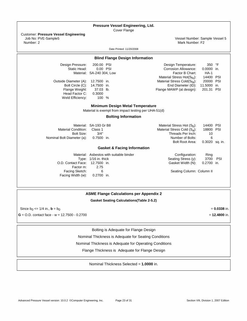
Pressure Vessel Engineering, Ltd.Cover Flange
Cus tomer : Pressure Vessel EngineeringJob No: PVE-Sample5 Vessel Number: Sample Vessel 5
Number : 2 Mark Number: F2
Date Printed: 11/20/2008
Blind Flange Design Information
Design Pressure: 200.00 PSI Design Temperature: 350 °FStatic Head: 0.00 PSI Corrosion Allowance: 0.0000 in.
Material: SA-240 304, Low Factor B Chart: HA-1Material Stress Hot(Sfo): 14400 PSI
Outside Diameter (A): 12.7500 in. Material Stress Cold(Sfa): 20000 PSIBolt Circle (C): 14.7500 in. End Diameter (ID): 11.5000 in.
Flange Weight: 37.03 lb. Flange MAWP (at design): 201.31 PSIHead Factor C: 0.3000
Weld Efficiency: 100 %
Minimum Design Metal TemperatureMaterial is exempt from impact testing per UHA-51(d)
Bolting Information
Material: SA-193 Gr B8 Material Stress Hot (Sb): 14400 PSIMaterial Condition: Class 1 Material Stress Cold (Sa): 18800 PSI
Bolt Size: 3/4" Threads Per Inch: 10Nominal Bolt Diameter (a): 0.7500 in. Number of Bolts: 6
Bolt Root Area: 0.3020 sq. in.
Gasket & Facing Information
Material: Asbestos with suitable binder Configuration: RingType: 1/16 in. thick Seating Stress (y): 3700 PS I
O.D. Contact Face: 12.7500 in. Gasket Width (N): 0.2700 in.Factor m: 2.75
Facing Sketch: 6 Seating Column: Column IIFacing Width (w): 0.2700 in.
ASME Flange Calculations per Appendix 2Gasket Seating Calculations(Table 2-5.2)
Since b0 <= 1/4 in., b = b0 = 0.0338 in .
G = O.D. contact face - w = 12.7500 - 0.2700 = 12 .4800 in.
Bolting is Adequate for Flange Design
Nominal Thickness is Adequate for Seating Conditions
Nominal Thickness is Adequate for Operating Conditions
Flange Thickness is Adequate for Flange Design
Nominal Thickness Selected = 1.0000 in .
Advanced Pressure Vessel version: 10.0.2 ©Computer Engineering, Inc. Section VIII, Division 1, 2007 EditionPage 23 of 31

Pressure Vessel Engineering, Ltd.Cover Flange
Job No: PVE-Sample5 Vessel Number: Sample Vessel 5Number : 2 Mark Number: F2
Date Printed: 11/20/2008
Load and Bolting Calculations - Internal Pressure
The absolute value of effective pressure “P” is used for calculations.
P =16 M
G+
4 FAG
+ Pint + Static Head =16 * 0
3.14159 * 12.4800+
4 * 03.14159 * 12.4800
+ 200.00 + 0.00 = 200.00 PS I
Minimum Wm2 = bGy = 3.14159 * 0.0338 * 12.4800 * 3700 = 4903 lb .
H =4
G P =3.14159
4* 12.4800 * 200.00 = 24465 lb .
Hp = 2b GmP = 2 * 0.0338 * 3.14159 * 12.4800 * 2.75 * 200.00 = 1458 lb.
Minimum Wm1 = H + Hp = 24465 + 1458 = 25923 lb .
Am1 =Wm1Sb
=2592314400
= 1.8002 sq. in.
Am2 =Wm2Sa
=4903
18800= 0.2608 sq. in.
Am = Greater of Am1 or Am2 = greater of 1.8002 or 0.2608 = 1.8002 sq. in.
Ab = Number of Bolts * Bolt Root Area = 6 * 0.3020 = 1.8120 sq. in.
W =(Am+ Ab)Sa
2=
(1.8002 + 1.8120) * 188002
= 33955 lb .
hG =(C - G)
2=
( 14.7500 - 12.4800 )2
= 1.1350 in .
Ab >= Am, Bolting is Adequate for Flange Design
Thickness Calculations
Operating Minimum t = GCPSE
+1.9Wm1hG
SEG= 12.4800 *
0.3000 * 200.0014400 * 1.00
+1.9 * 25923 * 1.1350
14400 * 1.00 * 12.4800= 0.9798 in .
Seating Minimum t = G1 .9W hGSEG
= 12.4800 *1.9 * 33955 * 1.1350
20000 * 1.00 * 12.4800= 0.5416 in .
Mininum t = maximum(0.9798, 0.5416) + CA = 0.9798 + 0.0000 = 0.9798 in .
Advanced Pressure Vessel version: 10.0.2 ©Computer Engineering, Inc. Section VIII, Division 1, 2007 EditionPage 24 of 31
Pressure Vessel Engineering, Ltd.Cus tomer : Pressure Vessel Engineering
Job No: PVE-Sample5 Vessel Number: Sample Vessel 5
Date Printed: 11/20/2008
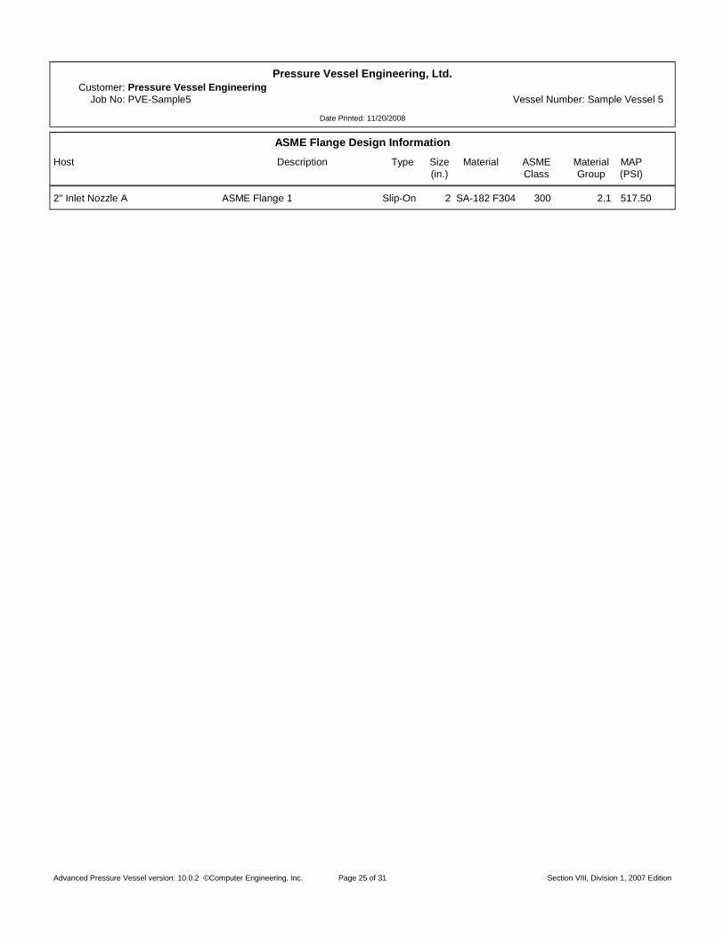
ASME Flange Design InformationHost Description Type S iz e Material ASM E Material MAP
( in . ) C las s Group (PSI)
2" Inlet Nozzle A ASME Flange 1 Slip-On 2 SA-182 F304 300 2.1 517.50
Advanced Pressure Vessel version: 10.0.2 ©Computer Engineering, Inc. Section VIII, Division 1, 2007 EditionPage 25 of 31
Pressure Vessel Engineering, Ltd.Cone to Cylinder 1
Cus tomer : Pressure Vessel EngineeringJob No: PVE-Sample5 Vessel Number: Sample Vessel 5
Number : 1
Date Printed: 11/20/2008
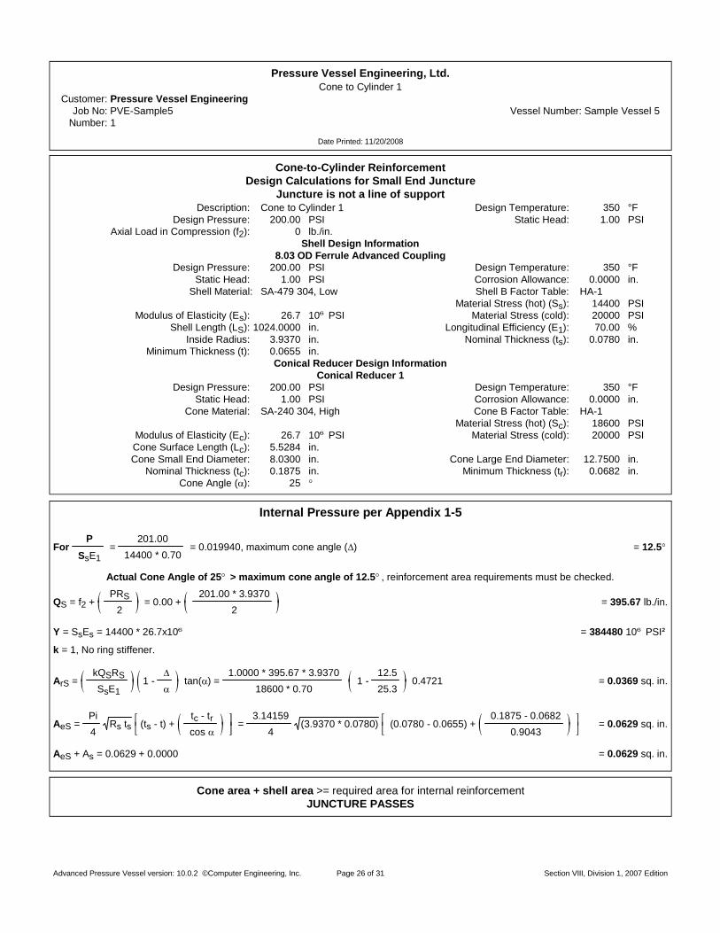
Cone-to-Cylinder ReinforcementDesign Calculations for Small End Juncture
Juncture is not a line of supportDescr ip t ion : Cone to Cylinder 1 Design Temperature: 350 °F
Design Pressure: 200.00 PSI Static Head: 1.00 PSIAxial Load in Compression (f2) : 0 lb./in.
Shell Design Information8.03 OD Ferrule Advanced Coupling
Design Pressure: 200.00 PSI Design Temperature: 350 °FStatic Head: 1.00 PSI Corrosion Allowance: 0.0000 in.
Shell Material: SA-479 304, Low Shell B Factor Table: HA-1Material Stress (hot) (Ss) : 14400 PSI
Modulus of Elasticity (Es) : 26.7 10 PS I Material Stress (cold): 20000 PSIShell Length (LS) : 1024.0000 in. Longitudinal Efficiency (E1) : 70.00 %
Inside Radius: 3.9370 in. Nominal Thickness (ts) : 0.0780 in.Minimum Thickness (t): 0.0655 in.
Conical Reducer Design InformationConical Reducer 1
Design Pressure: 200.00 PSI Design Temperature: 350 °FStatic Head: 1.00 PSI Corrosion Allowance: 0.0000 in.
Cone Material: SA-240 304, High Cone B Factor Table: HA-1Material Stress (hot) (Sc) : 18600 PSI
Modulus of Elasticity (Ec) : 26.7 10 PS I Material Stress (cold): 20000 PSICone Surface Length (Lc) : 5.5284 in.Cone Small End Diameter: 8.0300 in. Cone Large End Diameter: 12.7500 in.
Nominal Thickness (tc) : 0.1875 in. Minimum Thickness (tr) : 0.0682 in.Cone Angle ( ) : 25
Internal Pressure per Appendix 1-5
ForP
SsE1=
201.0014400 * 0.70
= 0.019940, maximum cone angle ( ) = 12.5
Actual Cone Angle of 25 > maximum cone angle of 12.5 , reinforcement area requirements must be checked.
QS = f2 +PRS
2= 0.00 +
201.00 * 3.93702
= 395.67 lb . / in .
Y = SsEs = 14400 * 26.7x10 = 384480 1 0 PS I
k = 1, No ring stiffener.
ArS =kQSRSSsE1
1 - tan ( ) =1.0000 * 395.67 * 3.9370
18600 * 0.701 -
12.525.3
0 .472 1 = 0.0369 sq. in.
AeS =Pi4
Rs ts (ts - t) +tc - trcos
=3.14159
4(3.9370 * 0.0780) (0.0780 - 0.0655) +
0.1875 - 0.06820.9043
= 0.0629 sq. in.
AeS + As = 0.0629 + 0.0000 = 0.0629 sq. in.
Cone area + shell area >= required area for internal reinforcementJUNCTURE PASSES
Advanced Pressure Vessel version: 10.0.2 ©Computer Engineering, Inc. Section VIII, Division 1, 2007 EditionPage 26 of 31

Pressure Vessel Engineering, Ltd.Cone to Cylinder 2
Cus tomer : Pressure Vessel EngineeringJob No: PVE-Sample5 Vessel Number: Sample Vessel 5
Number : 2
Date Printed: 11/20/2008
Cone-to-Cylinder ReinforcementDesign Calculations for Small End Juncture
Juncture is not a line of supportDescr ip t ion : Cone to Cylinder 2 Design Temperature: 350 °F
Design Pressure: 200.00 PSI Static Head: 1.00 PSIAxial Load in Compression (f2) : 0 lb./in.
Shell Design Information8.03 OD Ferrule Advanced Coupling
Design Pressure: 200.00 PSI Design Temperature: 350 °FStatic Head: 1.00 PSI Corrosion Allowance: 0.0000 in.
Shell Material: SA-479 304, Low Shell B Factor Table: HA-1Material Stress (hot) (Ss) : 14400 PSI
Modulus of Elasticity (Es) : 26.7 10 PS I Material Stress (cold): 20000 PSIShell Length (LS) : 2.0000 in. Longitudinal Efficiency (E1) : 70.00 %
Inside Radius: 3.9370 in. Nominal Thickness (ts) : 0.0780 in.Minimum Thickness (t): 0.0655 in.
Conical Reducer Design InformationConical Reducer 1
Design Pressure: 200.00 PSI Design Temperature: 350 °FStatic Head: 1.00 PSI Corrosion Allowance: 0.0000 in.
Cone Material: SA-240 304, High Cone B Factor Table: HA-1Material Stress (hot) (Sc) : 18600 PSI
Modulus of Elasticity (Ec) : 26.7 10 PS I Material Stress (cold): 20000 PSICone Surface Length (Lc) : 5.5284 in.Cone Small End Diameter: 8.0300 in. Cone Large End Diameter: 12.7500 in.
Nominal Thickness (tc) : 0.1875 in. Minimum Thickness (tr) : 0.0682 in.Cone Angle ( ) : 25
Internal Pressure per Appendix 1-5
ForP
SsE1=
201.0014400 * 0.70
= 0.019940, maximum cone angle ( ) = 12.5
Actual Cone Angle of 25 > maximum cone angle of 12.5 , reinforcement area requirements must be checked.
QS = f2 +PRS
2= 0.00 +
201.00 * 3.93702
= 395.67 lb . / in .
Y = SsEs = 14400 * 26.7x10 = 384480 1 0 PS I
k = 1, No ring stiffener.
ArS =kQSRSSsE1
1 - tan ( ) =1.0000 * 395.67 * 3.9370
18600 * 0.701 -
12.525.3
0 .472 1 = 0.0369 sq. in.
AeS =Pi4
Rs ts (ts - t) +tc - trcos
=3.14159
4(3.9370 * 0.0780) (0.0780 - 0.0655) +
0.1875 - 0.06820.9043
= 0.0629 sq. in.
AeS + As = 0.0629 + 0.0000 = 0.0629 sq. in.
Cone area + shell area >= required area for internal reinforcementJUNCTURE PASSES
Advanced Pressure Vessel version: 10.0.2 ©Computer Engineering, Inc. Section VIII, Division 1, 2007 EditionPage 27 of 31

Pressure Vessel Engineering, Ltd.Cone to Cylinder 3
Cus tomer : Pressure Vessel EngineeringJob No: PVE-Sample5 Vessel Number: Sample Vessel 5
Number : 3
Date Printed: 11/20/2008
Cone-to-Cylinder ReinforcementDesign Calculations for Large End Juncture
Juncture is not a line of supportDescr ip t ion : Cone to Cylinder 3 Design Temperature: 350 °F
Design Pressure: 200.00 PSI Static Head: 0.00 PSIAxial Load in Compression (f1) : 0 lb./in.
Shell Design InformationShell 2
Design Pressure: 200.00 PSI Design Temperature: 350 °FStatic Head: 1.00 PSI Corrosion Allowance: 0.0000 in.
Shell Material: SA-240 304H, High Shell B Factor Table: HA-1Material Stress (hot) (Ss) : 18600 PSI
Modulus of Elasticity (Es) : 26.7 10 PS I Material Stress (cold): 20000 PSIShell Length (LL) : 15.5000 in. Longitudinal Efficiency (E1) : 70.00 %
Inside Radius: 6.1870 in. Nominal Thickness (ts) : 0.1880 in.Minimum Thickness (t): 0.0974 in.
Conical Reducer Design InformationConical Reducer 1
Design Pressure: 200.00 PSI Design Temperature: 350 °FStatic Head: 1.00 PSI Corrosion Allowance: 0.0000 in.
Cone Material: SA-240 304, High Cone B Factor Table: HA-1Material Stress (hot) (Sc) : 18600 PSI
Modulus of Elasticity (Ec) : 26.7 10 PS I Material Stress (cold): 20000 PSICone Surface Length (Lc) : 5.5284 in.Cone Small End Diameter: 8.0300 in. Cone Large End Diameter: 12.7500 in.
Nominal Thickness (tc) : 0.1875 in. Minimum Thickness (tr) : 0.1077 in.Cone Angle ( ) : 25
Internal Pressure per Appendix 1-5
ForP
SsE1=
200.0018600 * 0.70
= 0.015361, maximum cone angle ( ) = 30.0
Actual Cone Angle of 25 <= maximum cone angle of 30.0 , reinforcement not required for internal pressure.
Maximum cone angle > Cone angle, reinforcement not needed for internal pressureJUNCTURE PASSES
Advanced Pressure Vessel version: 10.0.2 ©Computer Engineering, Inc. Section VIII, Division 1, 2007 EditionPage 28 of 31

Pressure Vessel Engineering, Ltd.Cus tomer : Pressure Vessel Engineering
Job No: PVE-Sample5 Vessel Number: Sample Vessel 5
Date Printed: 11/20/2008
MDMT Report by ComponentsDesign MDMT is -20 °F
Component Material Curve Pressure MDMT
Outlet 8" Ferrule Nozzle D SA-479 304, High Exempt per UCS-66(b)Shell 2 - thin shell SA-240 304, High Exempt per UCS-66(b)
10" Inlet Nozzle C SA-312 TP304 SMLS, Exempt per UCS-66(b)10" Inlet Flange SA-240 304H, High Exempt per UHA-51(d)
2" Heavy Ferrule Nozzle B SA-479 304, High Exempt per UCS-66(b)thick shell SA-312 TP304 SMLS, Exempt per UHA-51(d)Conical Reducer 1 SA-240 304, High Other Exemption
2" Inlet Nozzle A SA-312 TP304 SMLS, Exempt per UCS-66(b)Cover Flange SA-240 304, Low Exempt per UHA-51(d)
2"3000# Cplg N-E SA-182 F304 <=5", Hig Exempt per UCS-66(b)
The required design MDMT of -20 °F has been met or exceeded for the calculated MDMT values.
ASME Flanges Are Not Included in MDMT Calculations.
Advanced Pressure Vessel version: 10.0.2 ©Computer Engineering, Inc. Section VIII, Division 1, 2007 EditionPage 29 of 31

Pressure Vessel Engineering, Ltd.Cus tomer : Pressure Vessel Engineering
Job No: PVE-Sample5 Vessel Number: Sample Vessel 5
Date Printed: 11/20/2008
MAWP Report by Components
Vessel Component VesselMAWP MAWP MAWP
Design Static New & Cold Hot & Corroded Hot & CorrodedComponent Pressure Head UG-98(a) UG-98(b) UG-98(a)Outlet 8" Ferrule Nozzle D 200.00 PSI 1.00 PSI 331.85 PSI 309.55 PSI 308.55 PSIShell 2 - thin shell 200.00 PSI 1.00 PSI 341.24 PSI 318.29 PSI 317.29 PSI
10" Inlet Nozzle C 200.00 PSI 1.00 PSI 341.24 PSI 318.29 PSI 317.29 PSI10" Inlet Flange 200.00 PSI 1.00 PSI N C 476.81 PSI 475.81 PSI2" Heavy Ferrule Nozzle B 200.00 PSI 0.00 PSI 597.00 PSI 555.21 PSI 555.21 PSI
thick shell 200.00 PSI 1.00 PSI 1664.83 PSI 1549.16 PSI 1548.16 PSIConical Reducer 1 200.00 PSI 1.00 PSI 375.37 PSI 350.02 PSI 349.02 PSI
2" Inlet Nozzle A 200.00 PSI 1.00 PSI 660.56 PSI 615.25 PSI 614.25 PSI ASME Flange Class: 300 Gr:2.1 1.00 PSI 719.00 PSI 517.50 PSI 516.50 PSICover Flange 200.00 PSI 0.00 PSI 262.82 PSI 201.31 PSI 201.31 PSI
2"3000# Cplg N-E 200.00 PSI 0.00 PSI 289.37 PSI 208.34 PSI 208.34 PSI
NC = Not Calculated Inc = Incomplete
Summary
Component with the lowest vessel MAWP(New & Cold) : Cover FlangeThe lowest vessel MAWP(New & Cold) : 262.82 PS I
Component with the lowest vessel MAWP(Hot & Corroded) : Cover FlangeThe lowest vessel MAWP(Hot & Corroded) : 201.31 PS I
Pressures are exclusive of any external loads.
Flange pressures listed here do not consider external loadings
Advanced Pressure Vessel version: 10.0.2 ©Computer Engineering, Inc. Section VIII, Division 1, 2007 EditionPage 30 of 31

Pressure Vessel Engineering, Ltd.Cus tomer : Pressure Vessel Engineering
Job No: PVE-Sample5 Vessel Number: Sample Vessel 5
Date Printed: 11/20/2008
Summary Information
Dry Weight Flooded WeightShell 67.95 lb. 153.85 lb.Conical Reducer 9.62 lb. 23.99 lb.Nozzle 17.14 lb. 17.14 lb.Flange 68.13 lb. 68.13 lb.ASME Flange 7.00 lb. 7.00 lb.
_________________ _________________Tota ls 169.83 lb. 270.11 lb.
VolumeShell 10.28 Gal.Conical Reducer 1.72 Gal.Nozzle 1.68 Gal.
_________________Tota ls 13.68 Gal.
AreaShell 5.76 Sq. Ft.Conical Reducer 1.25 Sq. Ft.Nozzle 2.67 Sq. Ft.
_________________Tota ls 9.68 Sq. Ft.
Hydrostatic Test Information Par. UG-99(b)Gauge at Top
Calculated Test Pressure: 279.57 PSI
Specified Test Pressure: 260.00 PSI
This calculation assumes one chamber.
This calculation is limited by the lowest component pressure per chamber.
Advanced Pressure Vessel version: 10.0.2 ©Computer Engineering, Inc. Section VIII, Division 1, 2007 EditionPage 31 of 31