salt chlorine generator - high performance pool …/media/websites/pool/downloads/sanitizers/... ·...
TRANSCRIPT

IMPORTANT SAFETY INSTRUCTIONSREAD AND FOLLOW ALL INSTRUCTIONSSAVE THESE INSTRUCTIONSKEEP OUT OF REACH OF CHILDREN
iCHLOR™
SALT CHLORINE GENERATORMODEL iCHLOR 15, iCHLOR 30
INSTALLATION ANDUSER’S GUIDE
P/N 522709 Rev. B 2/21/17
If you have questions about ordering Pentair Aquatic Systems, (“Pentair”) replacement parts, and pool products, please use the following contact information:
CUSTOMER SERVICE / TECHNICAL SUPPORT
Customer Service (8 A.M. to 4:30 P.M. — Eastern and Pacific Times)
Phone: (800) 831-7133
Fax: (800) 284-4151
Web sitevisit www.pentairpool.com or www.staritepool.com to find information about Pentair products.
Technical Support
Sanford, North Carolina (8 A.M. to 4:30 P.M. ET)Phone: (919) 566-8000Fax: (919) 566-8920
Moorpark, California (8 A.M. to 4:30 P.M. PT)Phone: (805) 553-5000 (Ext. 5591)Fax: (805) 553-5515
iCHLOR™ Salt Chlorine Generator Installation and User’s Guide
TABLE OF CONTENTS
Important Warnings and Safety Instructions......
General Information..............................................Salt Chlorine Generator (SCG) OverviewiChlor SCG ModelsControl Panel and Cell DescriptionSystem ComponentsPower CenteriChlor 15 Power PackInstallation Requirements and Recommendations
Install Chlorine/Bromine Feeders after the iChlor Cell
Loop Plumbing DiagramiChlor SCG Plumbing Diagram
Pool Water PreparationDetermining Pool Size (Gallons of Water in
Your Pool)Determining Pool Size (Liters of Water in
Your Pool)
Control Panel Overview........................................Salt Level LEDsStatus LEDsDigital DisplayMore and Less Output ButtonsSelf-Cleaning
Water and Chemistry, Conditions and Precautions...................................................Pool Water Chemistry, Conditions and PrecautionsOptimum Pool Water Conditions for Salt Water
Pools (using the iChlor SCG)Chlorine TestingWhat Type of Salt to UseHow Much Salt to Use?Calculating the Saturation Index
TDS FactorLangelier Saturation Index Factors
Adding Salt to the Pool (How and How Much?)
Operation................................................................iChlor Operation
If Using a Pool Pump TimerStart-up Procedure (Super Chlorination)Sanitizer Output Settings and AdjustmentsOperating in WinterGeneral RecommendationsGeneral Cautions
ii
11222334
4556
6
6
777888
99
1011111112121213
1515151616161717
User Maintenance..................................................Daily ServiceWeekly ServiceMonthly ServiceUsage Hours MeterCleaning the Cell BladesWinterizing
Installation..............................................................Kit ContentsRequired ToolsiChlor Spacer Cell Selecting Model SizeInstalling the iChlor Cell AssemblyConnecting the Cell Power Cable to the Power
CenterConnecting the iChlor 15 to the Power PackSmartSense Flow Detection: Connecting the
iChlor to and IntelliFlo PumpSmartSense Cover DetectionConnecting the Power Center to IntelliTouch,
EasyTouch or SunTouch Control System Connecting iChlor Communication Cable
(RS-485) Connecting to a SunTouch System
Wiring AC Power from iChlor SCG and IntelliFlo to Automation Control System
Troubleshooting......................................................Troubleshooting ChartDiagnostic Mode
Technical Data.......................................................System Specifications - 110 VAC and 220 VAC 115 VAC Basic System Wiring220 VAC Basic System Wiring Power Center 230 and 115 VAC Transformer
Wiring iChlor 15 System Specifications and Wiring
18181818191920
212121222222
2323
2424
25
2627
27
292932
33333334
3435
i
IMPORTANT WARNINGS AND SAFETY INSTRUCTIONS
Important Notice: Attention Installer: This manual contains important information about the installation, operation and safe use of this product. This information should be given to the owner and/or operator of this equipment. When installing and using this electrical equipment, basic safety precautions should always be followed, including the following:
IMPORTANT SAFETY INSTRUCTIONS PERTAINING TO A RISK OF FIRE, ELECTRIC SHOCK, OR INJURY TO PERSONS. READ AND FOLLOW ALL INSTRUCTIONS. Before installing this product, read and follow all warning notices and instructions which are included. Failure to follow safety warnings and instructions can result in severe injury, death, or property damage. Call (800) 831-7133 for additional free copies of these instructions, or obtain a copy of these instructions at: http://www.pentairpool.com/misc/owners_manuals/sanitizers/iChlor_Owners.pdf
To reduce the risk of injury, do not permit children to use this product.
CHLORINE GAS BUILDUP CAN OCCUR WITH IMPROPER WIRING: To reduce the risk of personal injury the iChlor™ Salt Chlorine Generator (SCG) Power Center must be installed on and
wired to the load side of the time clock, electronically controlled switch, or relay load side, so that it will receive power only when the pool pump is on. Otherwise, dangerous chlorine gas buildup can occur. The SCG should never be energized when the pool pump is OFF and water is not flowing through the unit.
To reduce the risk of injury, service should only be personnel by a qualified pool service professional.
Never operate the iChlor Salt Chlorine Generator (SCG) without proper flow or water circulation. A build-up of flammable gases will result in hazardous conditions.
iChlor Salt Chlorine Generator (SCG) is for use with permanently-installed pools and may also be used with hot tubs and spas if so marked. Do not use with storable or steel pools. A permanently-
installed pool is constructed in or on the ground or in a building such that it cannot be readily disassembled for storage. A storable pool is constructed so that it is capable of being readily disassembled for storage and reassembled to its original integrity.
When using the iChlor Salt Chlorine Generator (SCG) with an IntelliTouch®, EasyTouch® or SunTouch® Control System, always wire the iChlor Salt Chlorine Generator (SCG) Power Center to
the pump side of the relay located in the IntelliTouch, EasyTouch or SunTouch load center. This wiring method does not require a ground fault circuit-interrupter (GFCI) to protect the circuit. A green colored terminal (or a wire connector marked “G”, “GR”, “Ground” or “Grounding”) is provided within the terminal compartment in the Power Center transformer enclosure. To reduce risk of electric shock, connect this terminal or connector to the grounding terminal of your electric service or supply panel with a conductor equivalent in size to the circuit conductors supplying this equipment. The power supply must be interconnected with pool pump motor power source. This insures the SCG and pool pump will switch on and off together.
Salt is an inherently corrosive material. While the levels of salt required for proper operation of the iChlor Salt Chlorine Generator (SCG) are relatively low when compared to sea water and other salt
solutions, placing any amount of salt in your pool increases the likelihood of corrosion or other deterioration of pool equipment and any surfaces used in and around your pool. Metal parts (including metal pools) and certain natural and man-made surfaces are particularly susceptible to corrosion and deterioration when used in and around salt water pools. Pentair Water Pool and Spa, Inc. (“Pentair”) does not represent or otherwise guarantee that the proper use of the (SCG) will prevent corrosion or other deterioration of pool equipment and any surfaces used in and around your pool. Consult your experienced pool professional, who should be able to advise you on the proper material selection, installation techniques for those materials, and the proper use, care and maintenance of those materials for your specific pool type and location in order to minimize the corrosion and deterioration that is inherent in and around salt water pools.
iCHLOR™ Salt Chlorine Generator Installation and User’s Guide
ii
IMPORTANT WARNING AND SAFETY INSTRUCTIONS
Use of chemicals other than those recommended may be hazardous. Even proper use of the recommended chemicals can be hazardous. Follow the Chemical Manufacturer’s Instructions.
To reduce the risk of electric shock, install iChlor Salt Chlorine Generator (SCG) a minimum of five (5) feet away from the inside wall of the pool.
Install the iChlor SCG a minimum of three (3) feet away from the heater outlet. A solid copper, bonding conductor not smaller than No. 8 AWG (8.4 mm) should be connected from the accessible wire connector on the unit to all metal parts of the swimming pool, spa, or hot tub
structure and to all electrical equipment, metal conduit, and metal piping within five (5) feet (1.5 m) of the inside walls of a swimming pool, spa, or hot tub, when the unit is installed within five (5) feet of the inside walls of the swimming pool, spa, or hot tub. Canada - Industry Canada (IC) - This device complies with RSS210 of Industry Canada. (1999)
FCC Standard - 47 CFR Part 15, Subpart C (Section 15.247). This version is limited to chapter 1 to chapter 11 by specified firmware controlled in the U.S.A.
Federal Communications Commission (FCC) - This device complies with Part 15 of the FCC Rules. Operation is subject to the following two conditions: (1) this device may not cause interference, and (2) this device must accept any interference, including interference that may cause undesired operation of the device.
Interference Statement - This equipment has been tested and found to comply with the limits for a Class B digital device, pursuant to Part 15 of the FCC Rules. These limits are designed to provide reasonable protection against harmful interference in a residential installation. This equipment generates, uses and can radiate radio frequency energy and, if not installed and used in accordance with the instructions, may cause harmful interference to radio communications. However, there is no guarantee that interference will not occur in a particular installation. If this equipment does cause harmful interference to radio or television reception, which can be determined by turning the equipment off and on, the user is encouraged to try to correct the interference by one or more of the following measures:
• Reorient or relocate the receiving antenna.• Increase the separation between the equipment and receiver.• Connect the equipment into an outlet on a circuit different from that to which the receiver is connected.• Consult the dealer or an experienced radio/TV technician for help.
Note: Modifications not expressly approved by the party responsible for FCC compliance could void the user’s authority to operate the device.
WHEN MIXING ACID WITH WATER, ALWAYS ADD ACID TO WATER. NEVER ADD WATER TO ACID.
The iChlor 15 Power Supply must be interconnected with pool pump motor power source. This ensures the iChlor SCG and pool pump will switch on and off together. When the iChlor 15 is
installed in Europe. The iChlor 15 power supply fuses must ONLY be obtained from the manufacturer.
The iChlor 15 Power Supply is only intended for use with the iChlor 15 cell, DO NOT PLUG ANY OTHER iChlor CELL INTO THIS POWER SUPPLY, SEVERE DAMAGE WILL RESULT.
iCHLOR™ Salt Chlorine Generator Installation and User’s Guide
iii
iCHLOR™ Salt Chlorine Generator Installation and User’s Guide
1
Salt Chlorine Generator (SCG) OverviewThe iChlor™ Salt Chlorine Generator (SCG) uses a process known as electrolysis to produce chlorine gas which immediately dissolves into a solution to create Hypochlorite and Hypochlorous acid (a pool and spa water sanitizer) from a low concentration of salt added to the pool water. Hypochlorite and Hypochlorous kill bacteria, oxidizes organic material, and kills algae, then reverts back to salt. The iChlor then reuses the salt and the process starts over again. The iChlor residential system is comprised of the iChlor cell and Power Center.
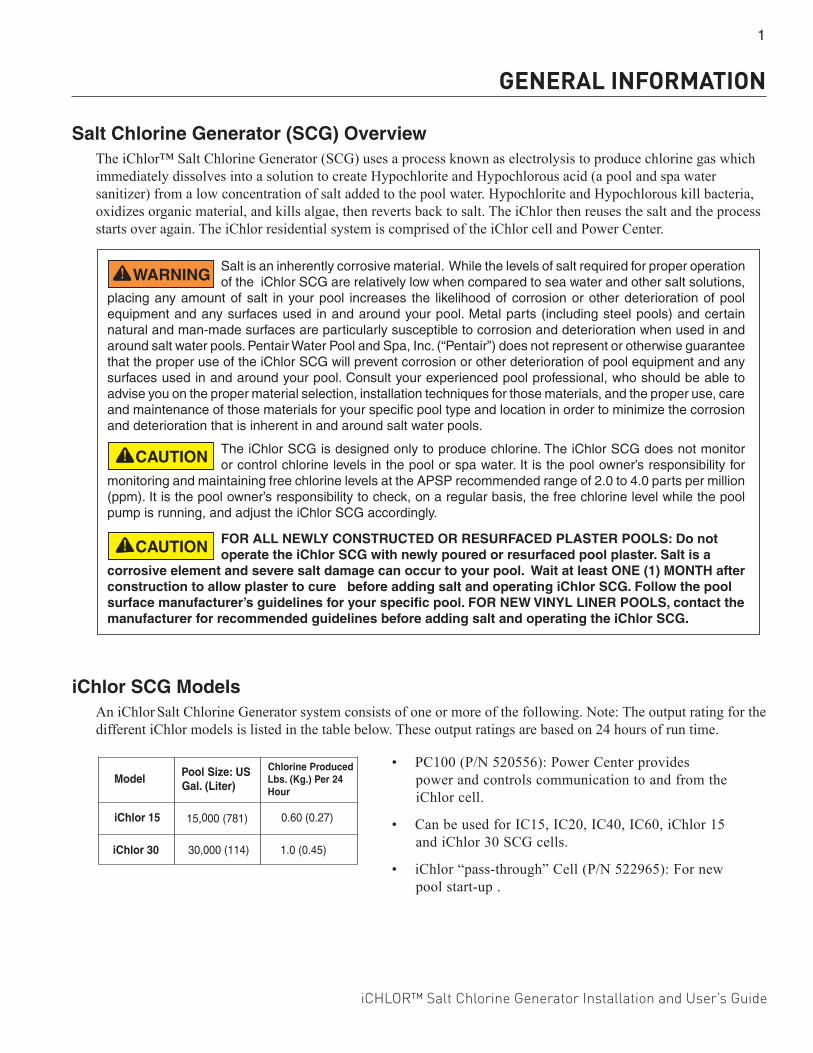
iChlor SCG ModelsAn iChlor Salt Chlorine Generator system consists of one or more of the following. Note: The output rating for the different iChlor models is listed in the table below. These output ratings are based on 24 hours of run time.
SU:eziSlooP)retiL(.laG
decudorPenirolhC42reP).gK(.sbL
ruoH
iChlor 15 )187(000,51 0.60 (0.27)
1.0 (0.45)iChlor 30 30,000 (114)
Model• PC100 (P/N 520556): Power Center provides
power and controls communication to and from the iChlor cell.
• Can be used for IC15, IC20, IC40, IC60, iChlor 15 and iChlor 30 SCG cells.
• iChlor “pass-through” Cell (P/N 522965): For new pool start-up .
The iChlor SCG is designed only to produce chlorine. The iChlor SCG does not monitor or control chlorine levels in the pool or spa water. It is the pool owner’s responsibility for
monitoring and maintaining free chlorine levels at the APSP recommended range of 2.0 to 4.0 parts per million (ppm). It is the pool owner’s responsibility to check, on a regular basis, the free chlorine level while the pool pump is running, and adjust the iChlor SCG accordingly.
Salt is an inherently corrosive material. While the levels of salt required for proper operation of the iChlor SCG are relatively low when compared to sea water and other salt solutions,
placing any amount of salt in your pool increases the likelihood of corrosion or other deterioration of pool equipment and any surfaces used in and around your pool. Metal parts (including steel pools) and certain natural and man-made surfaces are particularly susceptible to corrosion and deterioration when used in and around salt water pools. Pentair Water Pool and Spa, Inc. (“Pentair”) does not represent or otherwise guarantee that the proper use of the iChlor SCG will prevent corrosion or other deterioration of pool equipment and any surfaces used in and around your pool. Consult your experienced pool professional, who should be able to advise you on the proper material selection, installation techniques for those materials, and the proper use, care and maintenance of those materials for your specific pool type and location in order to minimize the corrosion and deterioration that is inherent in and around salt water pools.
FOR ALL NEWLY CONSTRUCTED OR RESURFACED PLASTER POOLS: Do not operate the iChlor SCG with newly poured or resurfaced pool plaster. Salt is a
corrosive element and severe salt damage can occur to your pool. Wait at least ONE (1) MONTH after construction to allow plaster to cure before adding salt and operating iChlor SCG. Follow the pool surface manufacturer’s guidelines for your specific pool. FOR NEW VINYL LINER POOLS, contact the manufacturer for recommended guidelines before adding salt and operating the iChlor SCG.
GENERAL INFORMATION
2
iCHLOR™ Salt Chlorine Generator Installation and User’s Guide
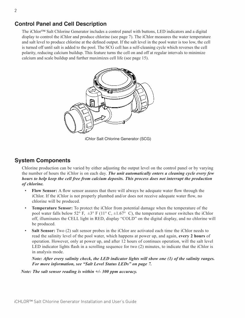
Control Panel and Cell DescriptionThe iChlor™ Salt Chlorine Generator includes a control panel with buttons, LED indicators and a digital display to control the iChlor and produce chlorine (see page 7). The iChlor measures the water temperature and salt level to produce chlorine at the defined output. If the salt level in the pool water is too low, the cell is turned off until salt is added to the pool. The SCG cell has a self-cleaning cycle which reverses the cell polarity, reducing calcium buildup. This feature turns the cell on and off at regular intervals to minimize calcium and scale buildup and further maximizes cell life (see page 15).
System Components
Chlorine production can be varied by either adjusting the output level on the control panel or by varying the number of hours the iChlor is on each day. The unit automatically enters a cleaning cycle every few hours to help keep the cell free from calcium deposits. This process does not interrupt the production of chlorine.
• Flow Sensor: A flow sensor assures that there will always be adequate water flow through the iChlor. If the iChlor is not properly plumbed and/or does not receive adequate water flow, no chlorine will be produced.
• Temperature Sensor: To protect the iChlor from potential damage when the temperature of the pool water falls below 52° F, ±3° F (11° C, ±1.67° C), the temperature sensor switches the iChlor off, illuminates the CELL light in RED, display “COLD” on the digital display, and no chlorine will be produced.
• Salt Sensor: Two (2) salt sensor probes in the iChlor are activated each time the iChlor needs to read the salinity level of the pool water, which happens at power up, and again, every 2 hours of operation. However, only at power up, and after 12 hours of continues operation, will the salt level LED indicator lights flash in a scrolling sequence for two (2) minutes, to indicate that the iChlor is in analysis mode.
Note: After every salinity check, the LED indicator lights will show one (1) of the salinity ranges. For more information, see “Salt Level Status LEDs” on page 7.
Note: The salt sensor reading is within +/- 300 ppm accuracy.
iChlor Salt Chlorine Generator (SCG)
iCHLOR™ Salt Chlorine Generator Installation and User’s Guide
3
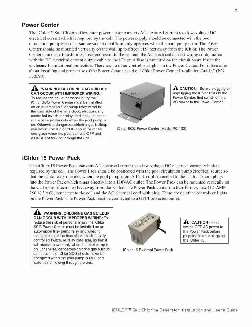
Power CenterThe iChlor™ Salt Chlorine Generator power center converts AC electrical current to a low-voltage DC electrical current which is required by the cell. The power supply should be connected with the pool circulation pump electrical source so that the iChlor only operates when the pool pump is on. The Power Center should be mounted vertically on the wall up to fifteen (15) feet away from the iChlor. The Power Center contains a transformer, fuse, connector to the cell and the AC electrical current wiring configuration with the DC electrical current output cable to the iChlor. A fuse is mounted on the circuit board inside the enclosure for additional protection. There are no other controls or lights on the Power Center. For information about installing and proper use of the Power Center, see the “iChlor Power Center Installation Guide,” (P/N 520590).
iChlor SCG Power Center (Model PC 100).
CAUTION - Before plugging or unplugging the iChlor SCG to the Power Center, first switch off the AC power to the Power Center.
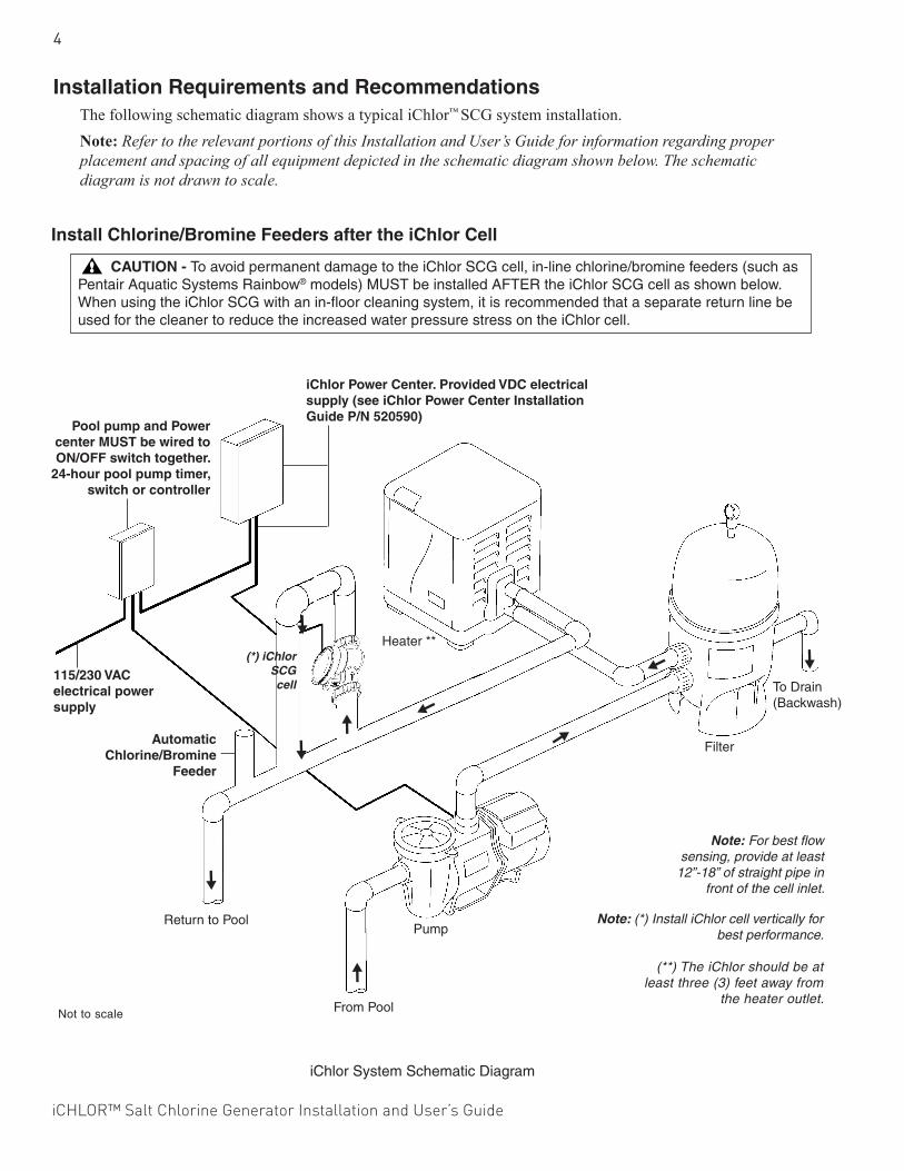
iChlor 15 External Power Pack
iChlor 15 Power PackThe iChlor 15 Power Pack converts AC electrical current to a low-voltage DC electrical current which is required by the cell. The Power Pack should be connected with the pool circulation pump electrical source so that the iChlor only operates when the pool pump is on. A 15 ft. cord connected to the iChlor 15 unit plugs into the Power Pack which plugs directly into a 110VAC outlet. The Power Pack can be mounted vertically on the wall up to fifteen (15) feet away from the iChlor. The Power Pack contains a transformer, fuse (1.5 AMP 250 V, 3 AG), connector to the cell and the AC electrical cord with plug. There are no other controls or lights on the Power Pack. The Power Pack must be connected to a GFCI protected outlet.
WARNING: CHLORINE GAS BUILDUP CAN OCCUR WITH IMPROPER WIRING: To reduce the risk of personal injury the iChlor SCG Power Center must be installed on an automation filter pump relay wired to the load side of the time clock, electronically controlled switch, or relay load side, so that it will receive power only when the pool pump is on. Otherwise, dangerous chlorine gas buildup can occur. The iChlor SCG should never be energized when the pool pump is OFF and water is not flowing through the unit.
WARNING: CHLORINE GAS BUILDUP CAN OCCUR WITH IMPROPER WIRING: To reduce the risk of personal injury the iChlor SCG Power Center must be installed on an automation filter pump relay and wired to the load side of the time clock, electronically controlled switch, or relay load side, so that it will receive power only when the pool pump is on. Otherwise, dangerous chlorine gas buildup can occur. The iChlor SCG should never be energized when the pool pump is OFF and water is not flowing through the unit.
CAUTION - First switch OFF AC power to the Power Pack before plugging in or unplugging the iChlor 15.
4
iCHLOR™ Salt Chlorine Generator Installation and User’s Guide
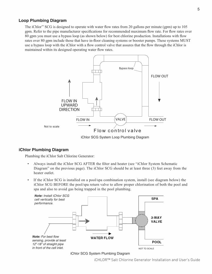
Installation Requirements and RecommendationsThe following schematic diagram shows a typical iChlor™ SCG system installation.Note: Refer to the relevant portions of this Installation and User’s Guide for information regarding proper placement and spacing of all equipment depicted in the schematic diagram shown below. The schematic diagram is not drawn to scale.
Install Chlorine/Bromine Feeders after the iChlor Cell
CAUTION - To avoid permanent damage to the iChlor SCG cell, in-line chlorine/bromine feeders (such as Pentair Aquatic Systems Rainbow® models) MUST be installed AFTER the iChlor SCG cell as shown below. When using the iChlor SCG with an in-floor cleaning system, it is recommended that a separate return line be used for the cleaner to reduce the increased water pressure stress on the iChlor cell.
Note: For best flow sensing, provide at least
12”-18” of straight pipe in front of the cell inlet.
Note: (*) Install iChlor cell vertically for best performance.
(**) The iChlor should be at
least three (3) feet away from the heater outlet.
iChlor System Schematic Diagram
Pool pump and Power center MUST be wired to ON/OFF switch together.
24-hour pool pump timer, switch or controller
iChlor Power Center. Provided VDC electrical supply (see iChlor Power Center Installation Guide P/N 520590)
115/230 VAC electrical power supply
(*) iChlor SCG cell
Automatic Chlorine/Bromine
Feeder
Return to Pool
From Pool
To Drain (Backwash)
Filter
Heater **
Pump
Not to scale
iCHLOR™ Salt Chlorine Generator Installation and User’s Guide
5
iChlor Plumbing DiagramPlumbing the iChlor Salt Chlorine Generator:
• Always install the iChlor SCG AFTER the filter and heater (see “iChlor System Schematic Diagram” on the previous page). The iChlor SCG should be at least three (3) feet away from the heater outlet.
• If the iChlor SCG is installed on a pool/spa combination system, install (see diagram below) the iChlor SCG BEFORE the pool/spa return valve to allow proper chlorination of both the pool and spa and also to avoid gas being trapped in the pool plumbing.
Loop Plumbing DiagramThe iChlor™ SCG is designed to operate with water flow rates from 20 gallons per minute (gpm) up to 105 gpm. Refer to the pipe manufacturer specifications for recommended maximum flow rate. For flow rates over 80 gpm you must use a bypass loop (as shown below) for best chlorine production. Installations with flow rates over 80 gpm include those that have in-floor cleaning systems or booster pumps. These systems MUST use a bypass loop with the iChlor with a flow control valve that assures that the flow through the iChlor is maintained within its designed operating water flow rates.
NOT TO SCALE
iChlor SCG System Plumbing Diagram
Not to scale
iChlor SCG System Loop Plumbing Diagram
UPWARD DIRECTION
Note: For best flow sensing, provide at least 12”-18” of straight pipe in front of the cell inlet.
Note: Install iChlor SCG cell vertically for best performance.

6
iCHLOR™ Salt Chlorine Generator Installation and User’s Guide
Pool Water Preparation
Determining Pool Size (Gallons of Water in Your Pool)
• Rectangular Pools: Length x width x average depth x 7.5• Circular Pools: Diameter x diameter x average depth x 5.9• Oval Pools: Length x width x average depth x 6.7• Sloping Sides: Multiply total gallons by 0.85 = gallon capacity
Determining Pool Size (liters of water in your pool)
• Rectangular Pools: Length x width (meters) x average depth x 1000• Circular Pools: Diameter x diameter x average depth x 785• Oval Pools: Length x width (meters) x average depth x 893• Sloping Sides: Multiply total liters by 0.85 = liter capacity.
CAUTION - Never use dry acid (sodium bisulfate) to adjust pH in arid geographic areas with excessive evaporation and minimal dilution of pool water with fresh water. A buildup of by-products can damage the iChlor SCG.
iCHLOR™ Salt Chlorine Generator Installation and User’s Guide
7
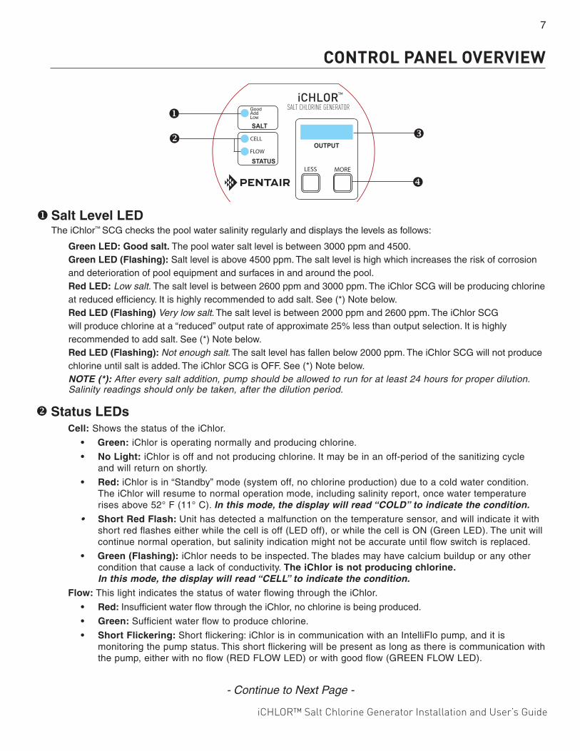
Salt Level LEDThe iChlor™ SCG checks the pool water salinity regularly and displays the levels as follows:
Green LED: Good salt. The pool water salt level is between 3000 ppm and 4500. Green LED (Flashing): Salt level is above 4500 ppm. The salt level is high which increases the risk of corrosion and deterioration of pool equipment and surfaces in and around the pool. Red LED: Low salt. The salt level is between 2600 ppm and 3000 ppm. The iChlor SCG will be producing chlorine at reduced efficiency. It is highly recommended to add salt. See (*) Note below. Red LED (Flashing) Very low salt. The salt level is between 2000 ppm and 2600 ppm. The iChlor SCG will produce chlorine at a “reduced” output rate of approximate 25% less than output selection. It is highly recommended to add salt. See (*) Note below. Red LED (Flashing): Not enough salt. The salt level has fallen below 2000 ppm. The iChlor SCG will not produce chlorine until salt is added. The iChlor SCG is OFF. See (*) Note below.NOTE (*): After every salt addition, pump should be allowed to run for at least 24 hours for proper dilution. Salinity readings should only be taken, after the dilution period.
Status LEDsCell: Shows the status of the iChlor.
• Green: iChlor is operating normally and producing chlorine.
• No Light: iChlor is off and not producing chlorine. It may be in an off-period of the sanitizing cycle and will return on shortly.
• Red: iChlor is in “Standby” mode (system off, no chlorine production) due to a cold water condition. The iChlor will resume to normal operation mode, including salinity report, once water temperature rises above 52° F (11° C). In this mode, the display will read “COLD” to indicate the condition.
• Short Red Flash: Unit has detected a malfunction on the temperature sensor, and will indicate it with short red flashes either while the cell is off (LED off), or while the cell is ON (Green LED). The unit will continue normal operation, but salinity indication might not be accurate until flow switch is replaced.
• Green (Flashing): iChlor needs to be inspected. The blades may have calcium buildup or any other condition that cause a lack of conductivity. The iChlor is not producing chlorine. In this mode, the display will read “CELL” to indicate the condition.
Flow: This light indicates the status of water flowing through the iChlor.
• Red: Insufficient water flow through the iChlor, no chlorine is being produced.
• Green: Sufficient water flow to produce chlorine.
• Short Flickering: Short flickering: iChlor is in communication with an IntelliFlo pump, and it is monitoring the pump status. This short flickering will be present as long as there is communication with the pump, either with no flow (RED FLOW LED) or with good flow (GREEN FLOW LED).
SALT CHLORINE GENERATOR
CERTIFIED TO NSF/ANSI 50
CONTROL PANEL OVERVIEW
- Continue to Next Page -
8
iCHLOR™ Salt Chlorine Generator Installation and User’s Guide
Digital DisplayThe iChlor SCG Digital Display shows “output %” and cell polarity, during normal operation.
To adjust output percentage:1. Press either LESS or MORE button. 2. Output will begin to flash on the digital display. This indicates that the iChlor is ready for the user to change
output levels.3. While output is flashing, press LESS or MORE button, to change output in 1% increments.
Note: Press and hold LESS or MORE button to change output in larger increments (5% jumps).4. Once the desired setting is programmed, and the user stops changing the setting, the digital display will stop
flashing after a few seconds. This indicates the end of the adjustment mode and the iChlor will return to normal operation.
Cell polarity indicator:Cell polarity is displayed as a small rotating character on the left-side of the output % display.• Clockwise rotation indicates Forward polarity on the blades.• Counterclockwise rotation indicates Reverse polarity on the blades.• Rotating feature also indicates chlorine production. If cell is OFF, character will not be displayed.
More and Less Output ButtonsThe MORE and LESS buttons control the percentage of time that the iChlor SCG is producing chlorine while the pump is on. Note: When an iChlor is connected to an IntelliTouch®, EasyTouch® or SunTouch® Control System, the LESS and MORE buttons are disabled and iChlor Sanitizer Output is controlled by the automation system.
MORE Button: Increases the output of the cell in 1% increments up to 100%. LESS Button: Decreases the output of the cell in 1% decrements to 0%.Boost Mode On/Off: Press both the MORE and LESS buttons together to turn Boost Mode on or off. Boost Mode sets the iChlor to run 100% for the next 24 hours of pool pump run time. If the time clock switches off the pump cycle, then switches power back on the next day, Boost Mode will continue until 24 hours has elapsed since Boost Mode was turned on or Boost Mode is canceled by the user. In boost mode, the display will alternate between “100%” output and a 24 hour countdown timer indicating the time left on boost mode.
Self-CleaningThe self-cleaning feature reduces scale buildup on the blades of the iChlor SCG. The self-cleaning feature is factory set to two (3) hours, and can be increased to four (4) or five (5) hours by the user.

iCHLOR™ Salt Chlorine Generator Installation and User’s Guide
9
WATER CHEMISTRY, CONDITIONS AND PRECAUTIONSThis section describes the start-up procedure and operating instructions for iChlor™ SCG.
Pool Water Chemistry, Conditions and Precautions1. New Pool Water: A recently filled or newly-refinished pool may contain undesirable matter. This
undesirable matter could interfere with the ability of the iChlor SCG to produce chlorine properly. Make sure the water is tested by a pool professional and properly balanced before switching on the iChlor SCG.
2. Super Chlorination burns out the swimmer waste that has combined with chlorine. This frees the chlorine for sanitizing. This is accomplished by raising the chlorine level quickly and dramatically. When the chlorine level is raised to ten (10) times the amount of combined chlorine the pool water is said to have been super chlorinated. As pool water is continuously passed through the iChlor SCG while the unit is powered on, the water inside the iChlor is being super chlorinated. Note: On initial start-up of a pool, it is best to super chlorinate using an outside source, i.e., use a shock treatment available at your local pool supplier.
3. Chloramines should not be present in pool water. Chloramines are formed when ammonia (which is found in urine and sweat) combine with free chlorine. This ties up the free chlorine in your pool and does not allow the chlorine in your pool to disinfect. Chloramines also burn the eyes and are foul smelling. Super Chlorinate to remove chloramines at the initial start-up of the pool and as needed to maintain proper levels of free chlorine.
4. Cyanuric acid is needed in outdoor pools to help to stabilize and maintain proper levels of chlorine. 90% of un-stabilized chlorine is destroyed by the UV radiation from the sun within two hours. Cyanuric acid stabilizes chlorine in water from UV degradation. When using the iChlor, the cyanuric acid level should be maintained between 30-50 ppm. See Table 2, on page 14. NOTE: DO NOT USE CYANURIC ACID IN INDOOR POOLS.
5. Total Dissolved Solids (TDS): Adding salt to pool water will raise the TDS level. While this does not adversely affect the pool water chemistry or clarity, the pool water professional testing for TDS must be made aware salt has been added to the iChlor system. The individual performing the TDS test (see page 12) may then subtract the salinity level to arrive at a TDS level that would be compatible to a TDS reading for a non-salt water pool.
Continue on next page.
Salt is an inherently corrosive material. While the levels of salt required for proper operation of the iChlor SCG are relatively low when compared to sea water and other salt solutions, placing any amount of salt in your pool increases the likelihood of corrosion or other deterioration of pool equipment and any surfaces used in and around your pool. Metal parts (including steel pools) and certain natural and man-made surfaces are particularly susceptible to corrosion and deterioration when used in and around salt water pools. Pentair Water Pool and Spa (“Pentair”) does not represent or otherwise guarantee that the proper use of the iChlor SCG will prevent corrosion or other deterioration of pool equipment and any surfaces used in and around your pool. Consult your experienced pool professional, who should be able to advise you on the proper material selection, installation techniques for those materials, and the proper use, care and maintenance of those materials for your specific pool type and location in order to minimize the corrosion and deterioration that is inherent in and around salt water pools.
CAUTION: The use of dry acid (sodium bisulfate) to adjust pool pH is discouraged especially in arid regions where pool water is subject to excessive evaporation and is not commonly diluted with fresh water. Dry acid can cause a buildup of by-products that can damage your chlorinator cell.
10
iCHLOR™ Salt Chlorine Generator Installation and User’s Guide
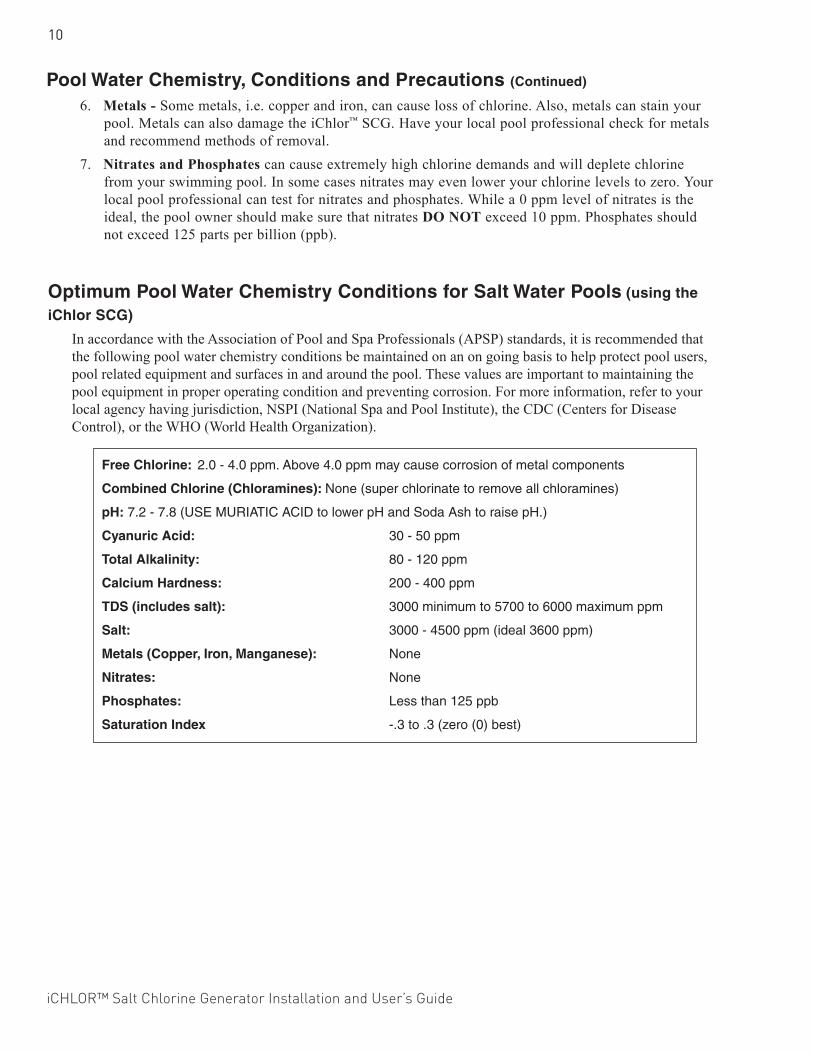
Optimum Pool Water Chemistry Conditions for Salt Water Pools (using the
iChlor SCG)
In accordance with the Association of Pool and Spa Professionals (APSP) standards, it is recommended that the following pool water chemistry conditions be maintained on an on going basis to help protect pool users, pool related equipment and surfaces in and around the pool. These values are important to maintaining the pool equipment in proper operating condition and preventing corrosion. For more information, refer to your local agency having jurisdiction, NSPI (National Spa and Pool Institute), the CDC (Centers for Disease Control), or the WHO (World Health Organization).
Free Chlorine: 2.0 - 4.0 ppm. Above 4.0 ppm may cause corrosion of metal components
Combined Chlorine (Chloramines): None (super chlorinate to remove all chloramines)
pH: 7.2 - 7.8 (USE MURIATIC ACID to lower pH and Soda Ash to raise pH.)
Cyanuric Acid: 30 - 50 ppm
Total Alkalinity: 80 - 120 ppm
Calcium Hardness: 200 - 400 ppm
TDS (includes salt): 3000 minimum to 5700 to 6000 maximum ppm
Salt: 3000 - 4500 ppm (ideal 3600 ppm)
Metals (Copper, Iron, Manganese): None
Nitrates: None
Phosphates: Less than 125 ppb
Saturation Index -.3 to .3 (zero (0) best)
Pool Water Chemistry, Conditions and Precautions (Continued)
6. Metals - Some metals, i.e. copper and iron, can cause loss of chlorine. Also, metals can stain your pool. Metals can also damage the iChlor™ SCG. Have your local pool professional check for metals and recommend methods of removal.
7. Nitrates and Phosphates can cause extremely high chlorine demands and will deplete chlorine from your swimming pool. In some cases nitrates may even lower your chlorine levels to zero. Your local pool professional can test for nitrates and phosphates. While a 0 ppm level of nitrates is the ideal, the pool owner should make sure that nitrates DO NOT exceed 10 ppm. Phosphates should not exceed 125 parts per billion (ppb).
iCHLOR™ Salt Chlorine Generator Installation and User’s Guide
11
Chlorine TestingIt is recommended that chlorine test samples be taken from two (2) locations in the pool. Compare the samples. A higher level should be found at the pool return line. The higher level at the pool return line indicates the iChlor™ SCG is producing chlorine. Take chlorine samples for testing at:
• The pool return line.• 18 inches (457 mm) below the surface and well away from the pool return line.
What Type of Salt to Use?Use salt that is at least 99.8% pure NaCl, sodium chloride. The preferred and recommended salt is an evaporated, granulated, food quality, non-iodized salt with no additives. Consult your salt supplier.
• Avoid using salt with anti-caking agents (sodium ferrocyanide, also known as YPS or yellow prussiate of soda). Filling agents can cause some discoloration of fittings and surface finishes in pool.
• Water conditioning salt pellets are compressed forms of evaporated salt and may be used, but will take longer to dissolve. Such pellets could damage pool plaster and other surfaces in and around the pool.
• Do not use calcium chloride or potassium chloride as a source of salt. (Use sodium chloride only).• Do not use Rock salt (insoluble impurities mixed with the rock salt can shorten the life of the iChlor.
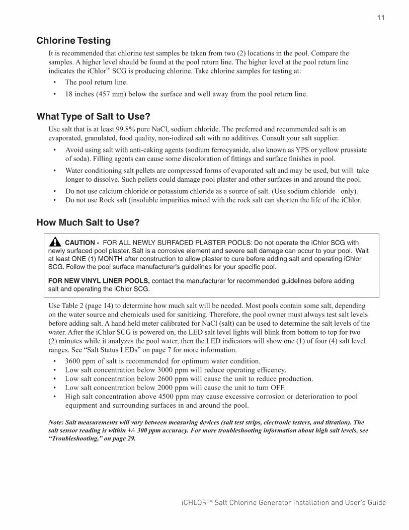
How Much Salt to Use?
Use Table 2 (page 14) to determine how much salt will be needed. Most pools contain some salt, depending on the water source and chemicals used for sanitizing. Therefore, the pool owner must always test salt levels before adding salt. A hand held meter calibrated for NaCl (salt) can be used to determine the salt levels of the water. After the iChlor SCG is powered on, the LED salt level lights will blink from bottom to top for two (2) minutes while it analyzes the pool water, then the LED indicators will show one (1) of four (4) salt level ranges. See “Salt Status LEDs” on page 7 for more information.
• 3600 ppm of salt is recommended for optimum water condition.• Low salt concentration below 3000 ppm will reduce operating efficency.• Low salt concentration below 2600 ppm will cause the unit to reduce production.• Low salt concentration below 2000 ppm will cause the unit to turn OFF.• High salt concentration above 4500 ppm may cause excessive corrosion or deterioration to pool
equipment and surrounding surfaces in and around the pool.
Note: Salt measurements will vary between measuring devices (salt test strips, electronic testers, and titration). The salt sensor reading is within +/- 300 ppm accuracy. For more troubleshooting information about high salt levels, see “Troubleshooting,” on page 29.
CAUTION - FOR ALL NEWLY SURFACED PLASTER POOLS: Do not operate the iChlor SCG with newly surfaced pool plaster. Salt is a corrosive element and severe salt damage can occur to your pool. Wait at least ONE (1) MONTH after construction to allow plaster to cure before adding salt and operating iChlor SCG. Follow the pool surface manufacturer’s guidelines for your specific pool.
FOR NEW VINYL LINER POOLS, contact the manufacturer for recommended guidelines before adding salt and operating the iChlor SCG.
12
iCHLOR™ Salt Chlorine Generator Installation and User’s Guide
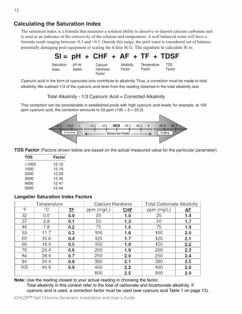
Calculating the Saturation IndexThe saturation index is a formula that measures a solution ability to dissolve or deposit calcium carbonate and is used as an indicator of the corrosivity of the solution and temperature. A well balanced water will have a formula result ranging between -0.3 and +0.3 Outside this range, the pool water is considered out of balance, potentially damaging pool equipment or scaling the iChlor SCG. The equation to calculate Si is:
Cyanuric acid in the form of cyanurate ions contribute to alkalinity. Thus, a correction must be made to total alkalinity. We subtract 1/3 of the cyanuric acid level from the reading obtained in the total alkalinity test.
Total Alkalinity - 1/3 Cyanuric Acid = Corrected Alkalinity
This correction can be considerable in established pools with high cyanuric acid levels; for example, at 100 ppm cyanuric acid, the correction amounts to 33 ppm (100 ÷ 3 = 33.3).
SI = pH + CHF + AF + TF + TDSFSaturation Index
pH as tested
Calcium Hardness Factor
Alkalinity Factor
Temperature Factor
TDS Factor
Note: Use the reading closest to your actual reading in choosing the factor. Total alkalinity in this context refer to the total of carbonate and bicarbonate alkalinity. If cyanuric acid is used, a correction factor must be used (see cyanuric acid Table 1 on page 13).
Langelier Saturation Index Factors
TDS Factor
<1000 12.10 1000 12.19 2000 12.29 3000 12.35 4000 12.41 5000 12.44
TDS Factor (Factors shown below are based on the actual measured value for the particular parameter)
iCHLOR™ Salt Chlorine Generator Installation and User’s Guide
13
Adding Salt to the Pool (How and How Much?)
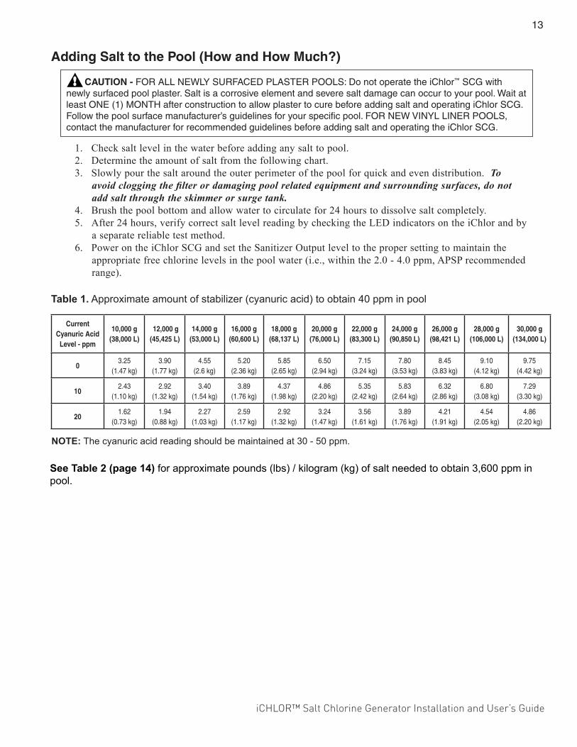
CAUTION - FOR ALL NEWLY SURFACED PLASTER POOLS: Do not operate the iChlor™ SCG with newly surfaced pool plaster. Salt is a corrosive element and severe salt damage can occur to your pool. Wait at least ONE (1) MONTH after construction to allow plaster to cure before adding salt and operating iChlor SCG. Follow the pool surface manufacturer’s guidelines for your specific pool. FOR NEW VINYL LINER POOLS, contact the manufacturer for recommended guidelines before adding salt and operating the iChlor SCG.
1. Check salt level in the water before adding any salt to pool.2. Determine the amount of salt from the following chart.3. Slowly pour the salt around the outer perimeter of the pool for quick and even distribution. To
avoid clogging the filter or damaging pool related equipment and surrounding surfaces, do not add salt through the skimmer or surge tank.
4. Brush the pool bottom and allow water to circulate for 24 hours to dissolve salt completely.5. After 24 hours, verify correct salt level reading by checking the LED indicators on the iChlor and by
a separate reliable test method.6. Power on the iChlor SCG and set the Sanitizer Output level to the proper setting to maintain the
appropriate free chlorine levels in the pool water (i.e., within the 2.0 - 4.0 ppm, APSP recommended range).
Table 1. Approximate amount of stabilizer (cyanuric acid) to obtain 40 ppm in pool
NOTE: The cyanuric acid reading should be maintained at 30 - 50 ppm.
Current Cyanuric Acid
Level - ppm
10,000 g (38,000 L)
12,000 g (45,425 L)
14,000 g (53,000 L)
16,000 g (60,600 L)
18,000 g (68,137 L)
20,000 g (76,000 L)
22,000 g (83,300 L)
24,000 g (90,850 L)
26,000 g (98,421 L)
28,000 g (106,000 L)
30,000 g (134,000 L)
03.25
(1.47 kg)3.90
(1.77 kg)4.55
(2.6 kg)5.20
(2.36 kg)5.85
(2.65 kg)6.50
(2.94 kg)7.15
(3.24 kg)7.80
(3.53 kg)8.45
(3.83 kg)9.10
(4.12 kg)9.75
(4.42 kg)
102.43
(1.10 kg)2.92
(1.32 kg)3.40
(1.54 kg)3.89
(1.76 kg)4.37
(1.98 kg)4.86
(2.20 kg)5.35
(2.42 kg)5.83
(2.64 kg)6.32
(2.86 kg)6.80
(3.08 kg)7.29
(3.30 kg)
201.62
(0.73 kg)1.94
(0.88 kg)2.27
(1.03 kg)2.59
(1.17 kg)2.92
(1.32 kg)3.24
(1.47 kg)3.56
(1.61 kg)3.89
(1.76 kg)4.21
(1.91 kg)4.54
(2.05 kg)4.86
(2.20 kg)
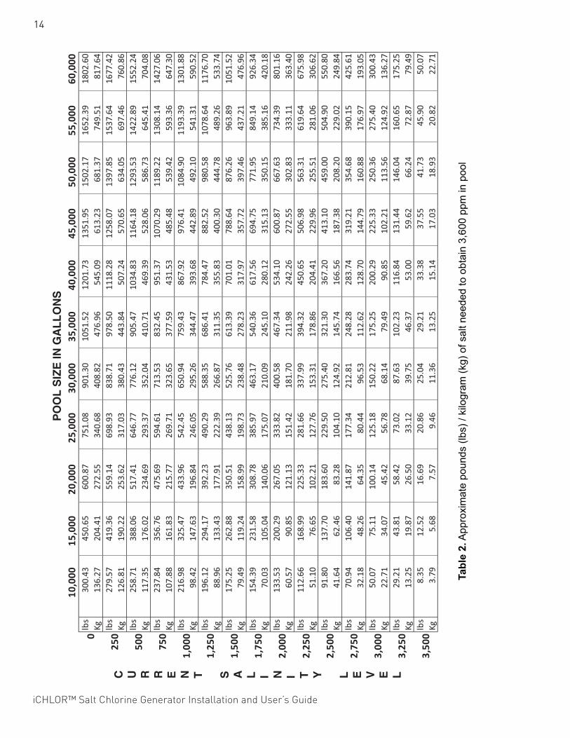
See Table 2 (page 14) for approximate pounds (lbs) / kilogram (kg) of salt needed to obtain 3,600 ppm in pool.
14
iCHLOR™ Salt Chlorine Generator Installation and User’s Guide
10,000
15,000
20,000
25,000
30,000
35,000
40,000
45,000
50,000
55,000
60,000
lbs
300.43
450.65
600.87
751.08
901.30
1051.52
1201.73
1351.95
1502.17
1652.39
1802.60
Kg136.27
204.41
272.55
340.68
408.82
476.96
545.09
613.23
681.37
749.51
817.64
lbs
279.57
419.36
559.14
698.93
838.71
978.50
1118.28
1258.07
1397.85
1537.64
1677.42
Kg126.81
190.22
253.62
317.03
380.43
443.84
507.24
570.65
634.05
697.46
760.86
lbs
258.71
388.06
517.41
646.77
776.12
905.47
1034.83
1164.18
1293.53
1422.89
1552.24
Kg117.35
176.02
234.69
293.37
352.04
410.71
469.39
528.06
586.73
645.41
704.08
lbs
237.84
356.76
475.69
594.61
713.53
832.45
951.37
1070.29
1189.22
1308.14
1427.06
Kg107.88
161.83
215.77
269.71
323.65
377.59
431.53
485.48
539.42
593.36
647.30
lbs
216.98
325.47
433.96
542.45
650.94
759.43
867.92
976.41
1084.90
1193.39
1301.88
Kg98.42
147.63
196.84
246.05
295.26
344.47
393.68
442.89
492.10
541.31
590.52
lbs
196.12
294.17
392.23
490.29
588.35
686.41
784.47
882.52
980.58
1078.64
1176.70
Kg88.96
133.43
177.91
222.39
266.87
311.35
355.83
400.30
444.78
489.26
533.74
lbs
175.25
262.88
350.51
438.13
525.76
613.39
701.01
788.64
876.26
963.89
1051.52
Kg79.49
119.24
158.99
198.73
238.48
278.23
317.97
357.72
397.46
437.21
476.96
lbs
154.39
231.58
308.78
385.97
463.17
540.36
617.56
694.75
771.95
849.14
926.34
Kg70.03
105.04
140.06
175.07
210.09
245.10
280.12
315.13
350.15
385.16
420.18
lbs
133.53
200.29
267.05
333.82
400.58
467.34
534.10
600.87
667.63
734.39
801.16
Kg60.57
90.85
121.13
151.42
181.70
211.98
242.26
272.55
302.83
333.11
363.40
lbs
112.66
168.99
225.33
281.66
337.99
394.32
450.65
506.98
563.31
619.64
675.98
Kg51.10
76.65
102.21
127.76
153.31
178.86
204.41
229.96
255.51
281.06
306.62
lbs
91.80
137.70
183.60
229.50
275.40
321.30
367.20
413.10
459.00
504.90
550.80
Kg41.64
62.46
83.28
104.10
124.92
145.74
166.56
187.38
208.20
229.02
249.84
lbs
70.94
106.40
141.87
177.34
212.81
248.28
283.74
319.21
354.68
390.15
425.61
Kg32.18
48.26
64.35
80.44
96.53
112.62
128.70
144.79
160.88
176.97
193.05
lbs
50.07
75.11
100.14
125.18
150.22
175.25
200.29
225.33
250.36
275.40
300.43
Kg22.71
34.07
45.42
56.78
68.14
79.49
90.85
102.21
113.56
124.92
136.27
lbs
29.21
43.81
58.42
73.02
87.63
102.23
116.84
131.44
146.04
160.65
175.25
Kg13.25
19.87
26.50
33.12
39.75
46.37
53.00
59.62
66.24
72.87
79.49
lbs
8.35
12.52
16.69
20.86
25.04
29.21
33.38
37.55
41.73
45.90
50.07
Kg3.79
5.68
7.57
9.46
11.36
13.25
15.14
17.03
18.93
20.82
22.71
0
250
500
3,50
0
3,25
0
3,00
0
750
1,00
0
1,25
0
1,50
0
1,75
0
2,00
0
2,25
0
2,50
0
2,75
0
C U R R E N T S A L I N I T Y L E V E L
PO
OL
SIZ
E IN
GA
LL
ON
S
Tabl
e 2.
App
roxi
mat
e po
unds
(lbs
) / k
ilogr
am (k
g) o
f sal
t nee
ded
to o
btai
n 3,
600
ppm
in p
ool
iCHLOR™ Salt Chlorine Generator Installation and User’s Guide
15
OPERATION This section describes the start up procedure and operating instructions for iChlor™ SCG. Before starting up and operating the iChlor SCG, the pool in which the iChlor SCG will be used must have been completed and filled with water for at least one (1) month (for plaster pools) and the pool water salt level must be stable and being maintained at 3600 ppm.
iChlor Operation IMPORTANT! Use of an external Pool Pump Timer is NOT Required
The iChlor is designed to supply a sufficient amount of chlorine to sanitize pool water on a daily basis. If the pool pump is continuously running and the iChlor is operated 24 hours a day at 100%, more chlorine would be generated than would be needed by most pools (2-4 ppm, per APSP recommendations). The iChlor has its own internal timer which cycles the electrolytic cell on and off depending on what percent the Sanitizer Output is set. For instance, at 100% the cell works all the time while the pool pump is running. When set at 80%, the cell is allowed to rest 20% of the time while the pool pump is running prolonging cell life. In order to fine tune iChlor to your pool size just increase or decrease the Sanitizer Output from 1% to 100% of the time. For more information, see “More and Less Output Buttons,” on page 8. CAUTION - The iChlor SCG is designed to only produce chlorine. The iChlor SCG does not monitor or control chlorine levels in the pool or spa water. It is the pool owner’s responsibility for monitoring and maintaining free chlorine levels at 2.0 to 4.0 parts per million (ppm) according to APSP recommendations.
CAUTION - Before attempting to operate iChlor refer to “General Recommendations and General Cautions,” on page 17, and “Pool Water Preparation,” on page 6.
If Using a Pool Pump TimerThe Association of Pool and Spa Professionals (APSP) recommends that all water in a residential pool pass through the filtration system at least once every six (6) hours, four (4) turns every 24 hours (referred to as pool water turnover). However, many factors have an effect on actual pump and filter system run times. Pool size, source of water, direct sun light, indoor/outdoor, screened/unscreened, filtration system, cold or hot weather, swimmer load, rain, organic debris, algae, etc., are all factors which contribute to either more or less pool pump and filter system run times. Because of these differences, it is extremely difficult to set a standard initial run time (starting point) for the pool pump and chlorinating system.Try initially setting the pool pump timer to twelve (12) hours. It will take a few days to achieve the correct amount of pool pump operating time. When iChlor™ SCG is wired with a pool pump timer results will vary greatly from one pool installation to the next, so this should be discussed with your pool professional.
The key points are:• Operate the pool pump at least the minimum time needed for good filtration and adequate chlorine
production by the iChlor SCG, according to your pool professional’s recommendations.• While pool pump timers can reduce energy consumption, the pool pump must be running for the
iChlor SCG to produce chlorine and must remain running long enough to maintain proper chlorine levels (i.e., 2.0 - 4.0 ppm of free available chlorine).
Note: Exception - For Cold Weather Operation: The unit turns off in water temperatures of 52° F, ±3° F (11° C, ±1.67° C) and below, and will not produce chlorine. This feature extends the life of the cell.
16
iCHLOR™ Salt Chlorine Generator Installation and User’s Guide
Start-up Procedure (Super Chlorination)Super Chlorination is recommended before pool start-up. Start out with clean, properly chlorinated, pool water from the beginning. The iChlor™ SCG will build up a sufficient level of chlorine for sanitation in several hours. However, if the pool water has a high demand from start-up the iChlor will not be able to produce enough chlorine to reach break-point chlorination. So, it is best to super chlorinate using an outside source at the time of pool start-up. Then, wait until the chlorine level has returned to 2.0 to 4.0 ppm before switching on the iChlor.
Sanitizer Output Settings and Adjustments• Switch on the pool pump switch or pool pump timer. The salt display will blink both LEDs (bottom
to top) for two (2) minutes, indicating that it has not checked the salt level yet. After two (2) minutes, the salt will be checked and one (1) of the salt level LEDs will be displayed. If the salinity is below 2600 ppm, the salt display will light the red LOW SALT indicator, and the CELL light will go blank, indicating there is not enough salt in the pool for chlorine to be produced.
• Set the Sanitizer Output to 60% by pressing the MORE or LESS button (see page 8).• After 24 hours, use a reliable test method to test the pool water for free available chlorine. The ideal
range to maintain is 2.0-4.0 ppm. If the free chlorine level of the pool water is too low, increase iChlor run time by pressing the MORE button. If the free chlorine level of the pool water is too high, decrease iChlor run time by pressing the LESS button.
• Due to a varying free chlorine demand of pool water, it may take a few days to determine the number of daily pool operating hours and “Sanitizer Output” percentage setting (see page 8) for your pool. Continue adjusting as necessary, allowing 24 hours between adjustments until the free chlorine level of the pool water is stabilized at 2.0 - 4.0 ppm, per APSP recommendations.
Operating in WinterThe iChlor SCG switches off and will not produce chlorine in water temperatures of 52° F, ±3° F (11° C, ±1.67° C) and below. This feature extends the life of the iChlor SCG. See “Winterizing,” on page 20.
iCHLOR™ Salt Chlorine Generator Installation and User’s Guide
17
General Recommendations• After new pool construction has been completed, before installing the iChlor™ SCG, install the
iChlor “empty cell” (P/N 520588) to remove debris from the pipes for thirty (30) days and to allow sufficient time for the pool plaster (or other similar material) to properly cure and seal.
• Read and keep this Installation and User’s Guide in a safe place.• Increase Sanitizer Output level as necessary after heavy rain (outdoor pools) and return to normal
afterwards.• Increase Sanitizer Output level when air and water temperature rise.• Increase Sanitizer Output level when number of pool users increase.• Use Cyanuric Acid ONLY as necessary to stabilize chlorine in outdoor pools. NOTE: DO NOT USE
CYANURIC ACID IN INDOOR POOLS.• Once a month take a pool water sample to a pool professional for a complete analysis.
General Cautions• Do not get fertilizer in your pool. Fertilizers contain nitrates, which cause a high
chlorine demand.
• Never use dry acid to adjust pH in arid geographic areas with excessive evaporation and minimal dilution. A buildup of by-products can damage the iChlor SCG.
• Do not add any pool water balancing chemicals (including salt) unless the iChlor SCG is switched off.
• Do not let the Cyanuric Acid level drop below 30 ppm in outdoor pools. NOTE: DO NOT USE CYANURIC ACID IN INDOOR POOLS.
18
iCHLOR™ Salt Chlorine Generator Installation and User’s Guide
USER MAINTENANCEThis section describes how to maintain the iChlor™ SCG.
Daily ServiceNone is needed.
Weekly service1. pH Level Test: Test the pH level of your pool water with a reliable test method. If necessary, adjust
according to your pool professional’s recommendations. APSP’s recommended ideal range for pH is 7.4 to 7.6, although 7.2 to 7.8 is an acceptable range under APSP’s guidelines.
Note: Never use dry acid (sodium bisulfate) to adjust pH in arid geographic areas with excessive evaporation and minimal dilution. A buildup of byproducts can damage the iChlor SCG.
2. Total Alkalinity Test: Test the pool water for total alkalinity with a reliable test method. Adjust according to your pool professional’s recommendations. APSP’s recommended ideal range for total alkalinity is 80 to 120 ppm.
3. Chlorine Test: Test the pool water the for free chlorine level with a reliable test method. Maintain ideal range by adjusting the iChlor SCG Sanitize Output settings. See “More and Less Output Buttons,” on page 8.
• Desired Free Chlorine is 2.0-4.0 ppm, per APSP recommendations. Note: Above 4.0 ppm of chlorine may cause excessive corrosion of metal components and possibly
cause damage to associated pool equipment. Note: It is recommended that free chlorine readings be taken from two (2) places in the pool, one at the
pool return line, the other well away from the pool return line. Compare the test results. A higher free chlorine level should be found at the pool return line. The higher free chlorine level at the pool return line indicates iChlor SCG is producing chlorine.
Monthly ServiceTo ensure that the correct chemical balance is maintained in your pool, it is important to perform the following recommended salt and pool water tests every month using a reliable test method.
1. Salt Level Test: Check salt display lights on the unit and check that the green “GOOD” light is on and is not flashing. • If the red LOW LED salt light is on. Add salt to the pool water (see charts beginning on
page 13).• If salt level does not rise after 24 hours, see “Troubleshooting,” page 29.To access salinity information through Diagnostic Mode:
Press and hold the MORE button for three (3) seconds until the lights scroll across the unit. This means the iChlor has entered Diagnostic Mode. Scroll through the screens using the MORE button until the salinity screen is displayed.
2. Pool Water Sample: Take a sample of the pool water to your local pool store for testing.3. Cyanuric Acid: Sample the pool water and test for cyanuric acid level using a reliable test method.
When using the iChlor SCG the recommended ideal cyanuric acid level is 30-50 ppm.4. Calcium Hardness: Test pool water for calcium hardness level using a reliable test method. If
necessary, adjust according to your pool professional’s recommendations. APSP’s recommended ideal range for calcium is 200 to 400 ppm for pools.
iCHLOR™ Salt Chlorine Generator Installation and User’s Guide
19
Monthly Service (Continued)
5. Metals Test: It is recommended that the pool water be sampled and tested periodically for the presence of metals such as copper, iron, and manganese. These metals can damage the iChlor SCG and other related pool equipment and should not be present in the pool water. If those metals are present, contact your pool professional.
6. TDS (Total Dissolved Solids): Test pool water for TDS level using test kit or by having a water sample tested by a pool professional. If necessary, adjust according to your pool professional’s recommendations. APSP standard of 3000 minimum to 6000 maximum ppm (which includes the salt) is recommended for salt pools.
Usage Hours MeterThe iChlor™ SCG provides a built-in cell “hours used” meter that reports how many hours iChlor has been operating. The iChlor SCG is designed to operate for approximately 10,000 hours before replacement is needed or roughly five (5) years of average use. To access the usage meter through Diagnostic mode:
Press and hold the MORE button for three (3) seconds until the lights scroll across the unit. The iChlor SCG will enter its diagnostic mode, showing hours of operation on the display.
Cleaning the Cell Blades1. Automatic Cleaning: The iChlor has an automatic cell blade cleaning feature that helps remove
scale deposits from the iChlor blades. Note: Automatic cleaning does not interrupt chlorine production. “Scale” is a white crusty deposit that forms in excessively hard water or from pool water that is out of balance and in a scaling condition. If the iChlor blades show excessive scaling, you need to perform an acid wash cleaning. Proceed to “Acid Wash Cleaning,” Step 2.
Note: Before acid washing, remove the loose calcium in the cell: Use a garden hose on the jet setting and spray directly into both ends of the cell. Most of this calcium buildup has a slushy consistency and will be blown out of the cell. Once the majority of the calcium has been removed, continue with acid washing which will now be more effective since most of the calcium has been removed.
2. Acid Wash Cleaning: If the iChlor blades show a tendency to scale, it is recommended that every two (2) months the iChlor be removed and inspected for scale formation and/or debris on the iChlor blades. High hardness areas may require more frequent cleaning. Some filters allow debris to pass through to the iChlor, possibly lodging between the blades. A small amount of scale formation is normal. If by looking through the iChlor it is observed that there is excessive scale formation between the blades or debris is present, the iChlor must be cleaned as follows:
a. Use a high-pressure jet of water from a garden hose. If the blades cannot be reasonably cleaned in this manner, acid cleaning is necessary.
b. To acid clean the iChlor SCG blades: Turn off power to the Power Center, then disconnect the iChlor SCG from the Power Center.
20
iCHLOR™ Salt Chlorine Generator Installation and User’s Guide
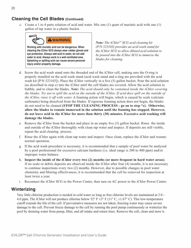
Working with muriatic acid can be dangerous. When cleaning the iChlor SCG always wear rubber gloves and eye protection. Always add acid to water, do not add water to acid. Always work in a well-ventilated area. Splashing or spilling acid can cause severe personal injury and/or property damage.
d. Screw the acid wash stand onto the threaded end of the iChlor cell, making sure the O-ring is properly installed on the acid wash stand (acid wash stand and o-ring are provided with the acid wash kit [P/N 523103]). Place the iChlor vertically in a five (5) gallon bucket. Pour the acid solution (as described in step c) into the iChlor until the cell blades are covered. Allow the acid solution to bubble, and to clean the blades. Note: The acid should only be contained inside the iChlor covering the blades. Try not to spill the acid on the outside of the iChlor. If acid does spill on the outside of the iChlor, rinse it off with water. A foaming action will begin, which is caused by scale (calcium carbonate) being dissolved from the blades. If rigorous foaming action does not begin, the blades do not need to be cleaned (STOP THE CLEANING PROCESS - go on to step “e). Otherwise, allow the blades to remain immersed in the solution until the foaming has stopped. However, do not leave acid in the iChlor for more than thirty (30) minutes. Excessive acid washing will damage the blades.
e. Remove the iChlor from the bucket and place in an empty five (5) gallon bucket. Rinse the inside and outside of the iChlor thoroughly with clean tap water and inspect. If deposits are still visible, repeat the acid cleaning process.
f. Rinse the iChlor again with clean tap water and inspect. Once clean, replace the iChlor and resume normal operation.
g. If the acid wash procedure is necessary, it is recommended that a sample of pool water be analyzed by a pool professional for excessive calcium hardness (i.e. ideal range is 200 to 400 ppm) and/or improper water balance.
h. Inspect the inside of the iChlor every two (2) months (or more frequent in hard water areas). If no scale or debris deposits are observed inside the iChlor after four (4) months, it is not necessary to continue inspections every two (2) months. However, due to possible changes in pool water chemistry and filtering effectiveness, it is recommended that the cell be removed for inspection at least twice a year.
i. Reconnect the iChlor SCG to the Power Center, then turn on AC power to the iChlor Power Center.
WinterizingVery little chlorine production is needed in cold water so long as free chlorine levels are maintained at 2.0 - 4.0 ppm. The iChlor will not produce chlorine below 52° F ±3° F (11° C, ±1.67° C). This low-temperature cutoff extends the life of the cell. If preventative measures are not taken, freezing water may cause severe damage to the cell. Prevent freeze damage to the cell by running the pool pump continuously or winterize the pool by draining water from pump, filter, and all intake and return lines. Remove the cell, clean and store it.
Cleaning the Cell Blades (Continued)
c. Create a 1 to 4 parts solution of acid and water. Mix one (1) quart of muriatic acid with one (1) gallon of tap water in a plastic bucket.
Note: The iChlor™ SCG acid cleaning kit (P/N 523103) provides an acid wash stand for the iChlor SCG to allow diluted acid solution to be poured into the iChlor SCG to immerse the blades for cleaning.
iCHLOR™ Salt Chlorine Generator Installation and User’s Guide
21
INSTALLATION
This section describes how to install the iChlor™ SCG into the pool plumbing system. Also, included are connection instructions for IntelliTouch®, EasyTouch® and SunTouch® Control Systems. Before installing, review the iChlor kit contents and required tools.Note: For Power Center installation instructions, see the “iChlor Power Center Installation Guide” (P/N 520590).Note: Salt is not provided. For details about the type of salt to use, see “What Type of Salt to Use,” on page 11.
Kit Contents- One iChlor SCG cell- Two (2) cell unions with two (2) o-rings- One iChlor adapter (to retrofit on existing iChlor SCG installations).- Installation and User’s Guide (this manual)- Cut-out template
Required Tools- Tape measure - Phillips and flathead screwdriver - Pliers - Hacksaw - An NSF approved all purpose PVC/CPVC/ABS cleaner primer - An NSF approved all purpose PVC/CPVC/ABS cement
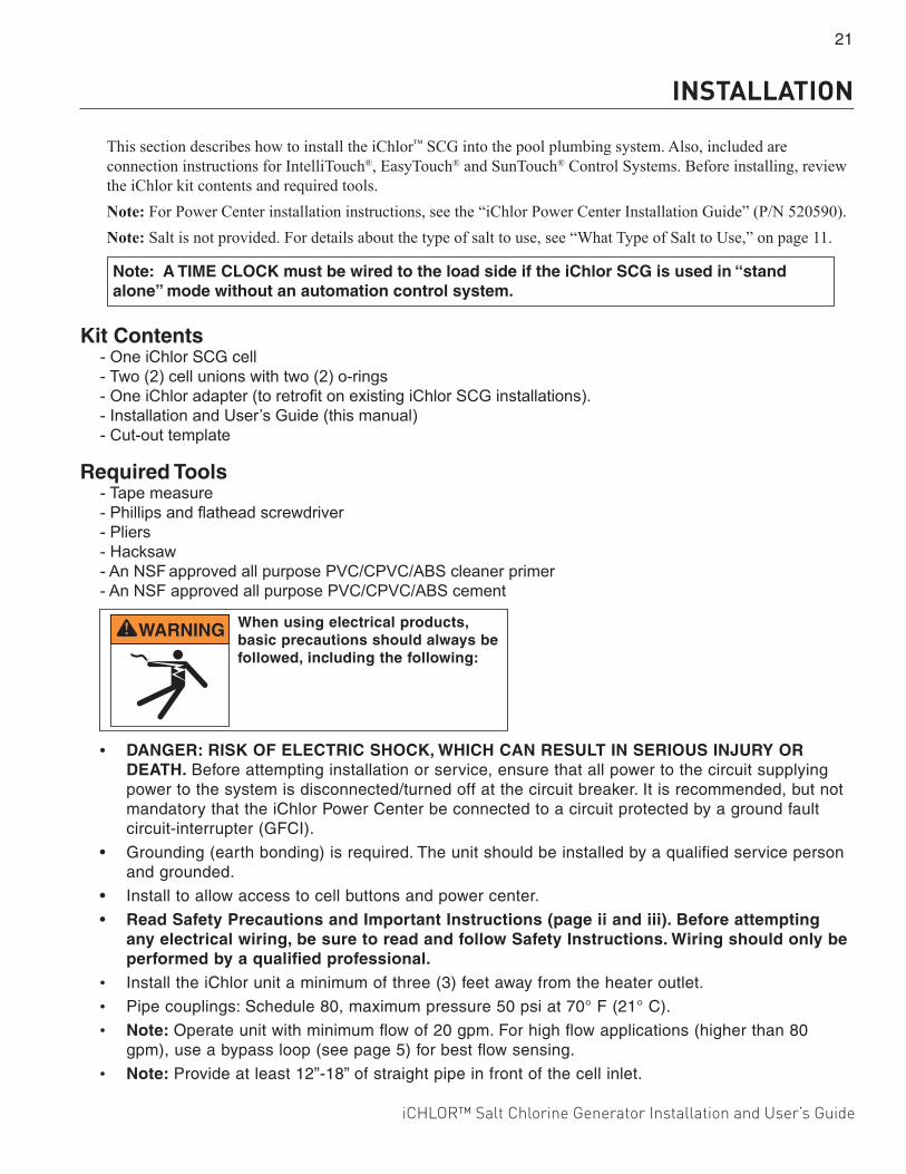
• DANGER: RISK OF ELECTRIC SHOCK, WHICH CAN RESULT IN SERIOUS INJURY OR DEATH. Before attempting installation or service, ensure that all power to the circuit supplying power to the system is disconnected/turned off at the circuit breaker. It is recommended, but not mandatory that the iChlor Power Center be connected to a circuit protected by a ground fault circuit-interrupter (GFCI).
• Grounding (earth bonding) is required. The unit should be installed by a qualified service person and grounded.
• Install to allow access to cell buttons and power center.
• Read Safety Precautions and Important Instructions (page ii and iii). Before attempting any electrical wiring, be sure to read and follow Safety Instructions. Wiring should only be performed by a qualified professional.
• Install the iChlor unit a minimum of three (3) feet away from the heater outlet.
• Pipe couplings: Schedule 80, maximum pressure 50 psi at 70° F (21° C).
• Note: Operate unit with minimum flow of 20 gpm. For high flow applications (higher than 80 gpm), use a bypass loop (see page 5) for best flow sensing.
• Note: Provide at least 12”-18” of straight pipe in front of the cell inlet.
When using electrical products, basic precautions should always be followed, including the following:
Note: A TIME CLOCK must be wired to the load side if the iChlor SCG is used in “stand alone” mode without an automation control system.
22
iCHLOR™ Salt Chlorine Generator Installation and User’s Guide
iChlor SCG Spacer Cell After new pool construction has been completed, in order to prevent debris from entering the iChlor™ SCG, it is recommended that the iChlor SCG spacer cell (P/N 522965) be installed before installing the iChlor SCG. After the pool system has flushed the debris from the pipes, remove the spacer cell and install the iChlor SCG.
Selecting Model Size (see chart on page 1)
Installing the iChlor Cell AssemblyInstall the iChlor cell assembly no closer than three (3) feet away from the heater outlet, if used. For more information see plumbing diagrams on page 4 and 5. Note: For best flow sensing, provide at least 12”-18” of straight pipe in front of the cell inlet.Note: After new pool construction has been completed, in order to prevent debris from entering the iChlor cell assembly, it is recommended that the iChlor SCG pass-through cell (P/N 522965) be installed before installing the iChlor SCG cell. After the pool system has flushed the debris from the pipes, remove the pass-through cell and install the iChlor cell.Note: Pipe couplings: Schedule 80, maximum pressure 50 psi at 70° F (21° C)
To install the iChlor SCG Cell: 1. Using the cut-out template provided with the iChlor, measure how much plumbing will have to be
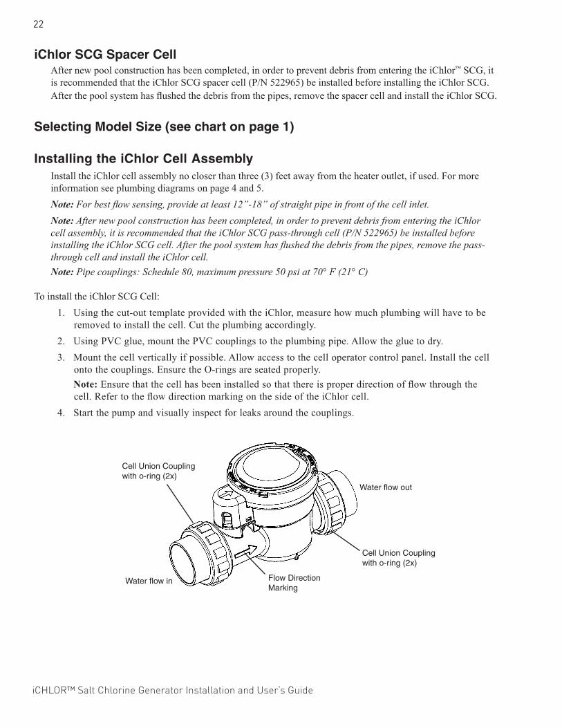
removed to install the cell. Cut the plumbing accordingly.2. Using PVC glue, mount the PVC couplings to the plumbing pipe. Allow the glue to dry.3. Mount the cell vertically if possible. Allow access to the cell operator control panel. Install the cell
onto the couplings. Ensure the O-rings are seated properly. Note: Ensure that the cell has been installed so that there is proper direction of flow through the
cell. Refer to the flow direction marking on the side of the iChlor cell.4. Start the pump and visually inspect for leaks around the couplings.
Water flow in
Water flow out
Cell Union Coupling with o-ring (2x)
Cell Union Coupling with o-ring (2x)
Flow Direction Marking

iCHLOR™ Salt Chlorine Generator Installation and User’s Guide
23
Connecting the iChlor Cell Power Cable to the Power Center
After the cell installation is completed, connect iChlor SCG cell’s power cable to the Power Center:
1. Be sure that AC power is switched OFF before connecting the power cord to the Power Center or the cell may short circuit.
2. Align the four (4) pins of the cell power cord connector with the socket on the bottom of the Power Center and insert the connector. Turn the round socket nut until it locks the connector in place.
Connector socket nut.
To cell assembly
Connecting the iChlor 15 to the Power Pack
After the iChlor 15 cell installation is completed, connect the cell power cable to the Power Pack:
• Align the four (4) pins of the cell power cord connector with the socket on the side of the Power Pack and insert the connector. Turn the round socket nut until it locks the connector in place.
iChlor SCG Power Pack socket
iChlor 15 Power Pack
WARNING - Switch OFF main system power to the Power Center before making any connections.
WARNING - Switch OFF main system power to the Power Pack before making any connections.
24
iCHLOR™ Salt Chlorine Generator Installation and User’s Guide
SmartSense™ Flow Detection: Connecting the iChlor SCG to an IntelliFlo pump (stand-alone mode).
SmartSense Flow Detection technology allows the connection of an IntelliFlo® Variable Speed Pump via RS-485 communication, to an iChlor™ SCG power center while in stand-alone mode, by simply attaching the RS-485 cable from the pump, to the RS-485 connector located in the iChlor Power Center (see iChlor Power Center Wiring Diagram at the bottom of the next page).SmartSense is a safety feature that will continually monitor the status of the IntelliFlo pump before generating chlorine.
SmartSense Cover Detection: Pool Cover DetectionSmartSense Cover Detection technology allows iChlor cells to receive a “pool cover” signal and reduce the chlorine output when the cover is closed*
• Will detect pool cover closed, and default to 5% output the first time.• Will allow user to set desired output for “cover closed” and will keep the setting for future “cover
closed” events.• Under “cover closed” condition, will limit max. Output setting to 50%.• “Cover closed” signal is a dry contact input to the power center board.
*This feature requires a “pool cover-compatible” PC100 or an upgraded PC100 electronic board (for previous PC100 versions)
iCHLOR™ Salt Chlorine Generator Installation and User’s Guide
25
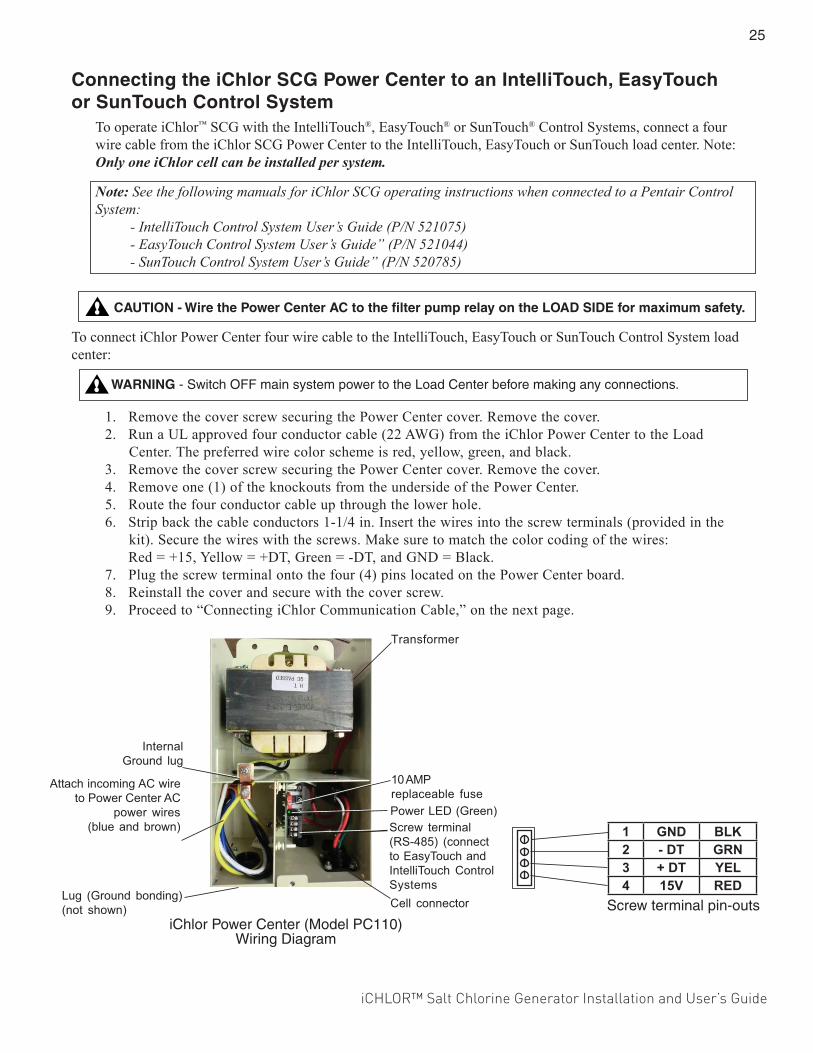
Connecting the iChlor SCG Power Center to an IntelliTouch, EasyTouch or SunTouch Control System
To operate iChlor™ SCG with the IntelliTouch®, EasyTouch® or SunTouch® Control Systems, connect a four wire cable from the iChlor SCG Power Center to the IntelliTouch, EasyTouch or SunTouch load center. Note: Only one iChlor cell can be installed per system.
Note: See the following manuals for iChlor SCG operating instructions when connected to a Pentair Control System: - IntelliTouch Control System User’s Guide (P/N 521075) - EasyTouch Control System User’s Guide” (P/N 521044) - SunTouch Control System User’s Guide” (P/N 520785)
CAUTION - Wire the Power Center AC to the filter pump relay on the LOAD SIDE for maximum safety.
To connect iChlor Power Center four wire cable to the IntelliTouch, EasyTouch or SunTouch Control System load center:
1. Remove the cover screw securing the Power Center cover. Remove the cover.2. Run a UL approved four conductor cable (22 AWG) from the iChlor Power Center to the Load
Center. The preferred wire color scheme is red, yellow, green, and black. 3. Remove the cover screw securing the Power Center cover. Remove the cover.4. Remove one (1) of the knockouts from the underside of the Power Center.5. Route the four conductor cable up through the lower hole.6. Strip back the cable conductors 1-1/4 in. Insert the wires into the screw terminals (provided in the
kit). Secure the wires with the screws. Make sure to match the color coding of the wires: Red = +15, Yellow = +DT, Green = -DT, and GND = Black.7. Plug the screw terminal onto the four (4) pins located on the Power Center board.8. Reinstall the cover and secure with the cover screw.9. Proceed to “Connecting iChlor Communication Cable,” on the next page.
WARNING - Switch OFF main system power to the Load Center before making any connections.
Screw terminal pin-outs
1 GND BLK2 - DT GRN3 + DT YEL4 15V RED
Cell connector
Transformer
Screw terminal(RS-485) (connectto EasyTouch andIntelliTouch ControlSystems
Attach incoming AC wireto Power Center AC
power wires(blue and brown)
Lug (Ground bonding)(not shown)
InternalGround lug
10 AMPreplaceable fusePower LED (Green)
iChlor Power Center (Model PC110)Wiring Diagram
26
iCHLOR™ Salt Chlorine Generator Installation and User’s Guide
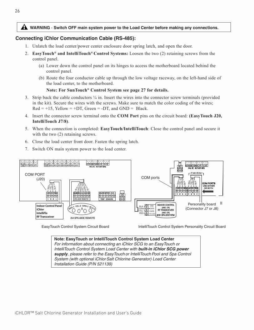
Connecting iChlor Communication Cable (RS-485):
1. Unlatch the load center/power center enclosure door spring latch, and open the door.2. EasyTouch® and IntelliTouch® Control Systems: Loosen the two (2) retaining screws from the
control panel.(a) Lower down the control panel on its hinges to access the motherboard located behind the
control panel.(b) Route the four conductor cable up through the low voltage raceway, on the left-hand side of
the load center, to the motherboard.Note: For SunTouch® Control System see page 27 for details.
3. Strip back the cable conductors ¼ in. Insert the wires into the connector screw terminals (provided in the kit). Secure the wires with the screws. Make sure to match the color coding of the wires; Red = +15, Yellow = +DT, Green = -DT, and GND = Black.
4. Insert the connector screw terminal onto the COM Port pins on the circuit board: (EasyTouch J20, IntelliTouch J7/8).
5. When the connection is completed: EasyTouch/IntelliTouch: Close the control panel and secure it with the two (2) retaining screws.
6. Close the load center front door. Fasten the spring latch.7. Switch ON main system power to the load center.
BLKGRNYELRED
Personality board(Connector J7 or J8)
�
COM ports
IntelliTouch Control System Personality Circuit Board
Indoor Control PaneliChlorIntelliFloRF Transceiver
COM PORT (J20)
EasyTouch Control System Circuit Board
WARNING - Switch OFF main system power to the Load Center before making any connections.
Note: EasyTouch or IntelliTouch Control System Load Center For information about connecting an iChlor SCG to an EasyTouch or IntelliTouch Control System Load Center with built-in iChlor SCG power supply, please refer to the EasyTouch or IntelliTouch Pool and Spa Control System (with optional iChlor Salt Chlorine Generator) Load Center Installation Guide (P/N 521139)
iCHLOR™ Salt Chlorine Generator Installation and User’s Guide
27
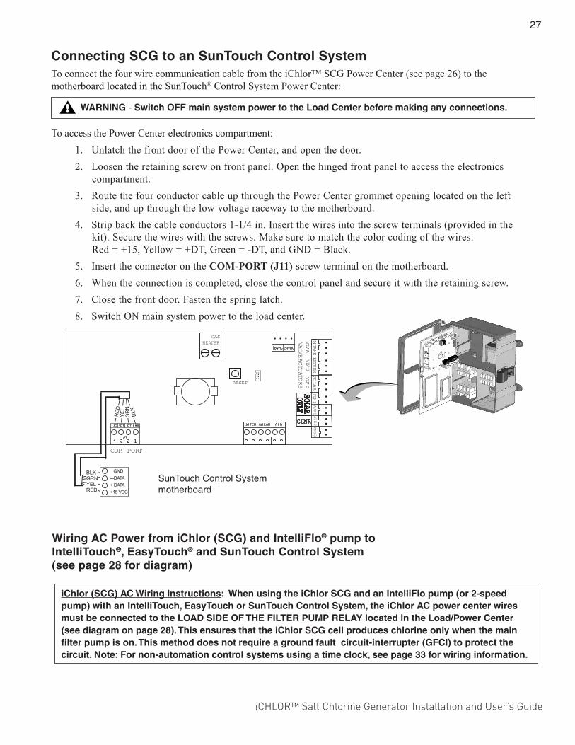
Connecting SCG to an SunTouch Control System To connect the four wire communication cable from the iChlor™ SCG Power Center (see page 26) to the motherboard located in the SunTouch® Control System Power Center:
To access the Power Center electronics compartment:1. Unlatch the front door of the Power Center, and open the door.2. Loosen the retaining screw on front panel. Open the hinged front panel to access the electronics
compartment. 3. Route the four conductor cable up through the Power Center grommet opening located on the left
side, and up through the low voltage raceway to the motherboard.4. Strip back the cable conductors 1-1/4 in. Insert the wires into the screw terminals (provided in the
kit). Secure the wires with the screws. Make sure to match the color coding of the wires: Red = +15, Yellow = +DT, Green = -DT, and GND = Black.
5. Insert the connector on the COM-PORT (J11) screw terminal on the motherboard.6. When the connection is completed, close the control panel and secure it with the retaining screw.7. Close the front door. Fasten the spring latch.8. Switch ON main system power to the load center.
VALVE A
CTUATO
RS
COM PORT
INTAKE
RETURN
SOLAR
AUX 3
PUMP
AUX 2
AUX 1
VLV AVLV B
VLV C
ONLYSOLAR
CLNR
GASHEATER
RESET
SunTouch Control System motherboard
Wiring AC Power from iChlor (SCG) and IntelliFlo® pump to IntelliTouch®, EasyTouch® and SunTouch Control System (see page 28 for diagram)
iChlor (SCG) AC Wiring Instructions: When using the iChlor SCG and an IntelliFlo pump (or 2-speed pump) with an IntelliTouch, EasyTouch or SunTouch Control System, the iChlor AC power center wires must be connected to the LOAD SIDE OF THE FILTER PUMP RELAY located in the Load/Power Center (see diagram on page 28). This ensures that the iChlor SCG cell produces chlorine only when the main filter pump is on. This method does not require a ground fault circuit-interrupter (GFCI) to protect the circuit. Note: For non-automation control systems using a time clock, see page 33 for wiring information.
WARNING - Switch OFF main system power to the Load Center before making any connections.
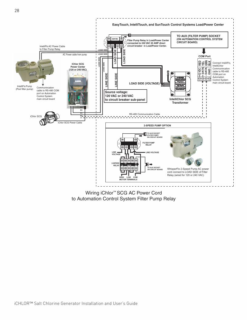
28
iCHLOR™ Salt Chlorine Generator Installation and User’s Guide
Wiring iChlor™ SCG AC Power Cord to Automation Control System Filter Pump Relay
WhisperFlo 2-Speed Pump AC powercord connect to LOAD SIDE of FilterRelay (wired for 120 or 240 VAC)
RS-485 Communication Cable
IntelliFlo Pump(Pool filter pump)
iChlor SCGPower Center
(120 or 240 VAC)
iChlor SCG
iChlor SCG Power Cable
IntelliFlo AC Power Cableto Filter Pump Relay
Communincationcable to RS-485 COMport on AutomationControl Systemmain circuit board
Filter Pump Relay in Load/Power Centerconnected to 240 VAC 20 AMP directcircuit breaker in Load/Power Center.
RED
YEL
GRN
BLK
LOAD SIDE (VOLTAGE)
LO
AD
SID
E
LIN
E S
IDE
Source voltage:120 VAC or 240 VAC to circuit breaker sub-panel IntelliChlor SCG
Transformer
LIN
E S
IDE
LO
AD
SID
E
Connect IntelliFlo,IntelliChlorCommunincationcable to RS-485COM port onAutomationControl Systemmain circuit board
TO AUX (FILTER PUMP) SOCKET (ON AUTOMATION CONTROL SYSTEMCIRCUIT BOARD)
EasyTouch, IntelliTouch, and SunTouch Control Systems Load/Power Center
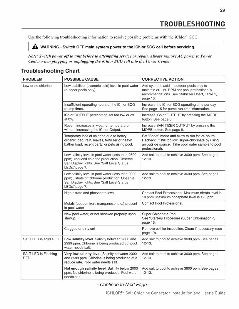
iCHLOR™ Salt Chlorine Generator Installation and User’s Guide
29
TROUBLESHOOTING Use the following troubleshooting information to resolve possible problems with the iChlor™ SCG.
Note: Switch power off to unit before to attempting service or repair. Always remove AC power to Power Center when plugging or unplugging the iChlor SCG cell into the Power Center.
Troubleshooting ChartPROBLEM POSSIBLE CAUSE CORRECTIVE ACTION
Low or no chlorine. Low stabilizer (cyanuric acid) level in pool water (outdoor pools only).
Add cyanuric acid in outdoor pools only to maintain 30 - 50 PPM per pool professional’s recommendations. See Stabilizer Chart, Table 1, page 13.
Insufficient operating hours of the iChlor SCG (pump time).
Increase the iChlor SCG operating time per day. See page 15 for pump run time information.
iChlor OUTPUT percentage set too low or off at 0%.
Increase iChlor OUTPUT by pressing the MORE button. See page 8.
Recent increases in weather temperature without increasing the iChlor Output.
Increase SANITIZER OUTPUT by pressing the MORE button. See page 8.
Temporary loss of chlorine due to heavy organic load, rain, leaves, fertilizer or heavy bather load, recent party, or pets using pool.
Set “Boost” mode and allow to run for 24 hours. Recheck, If still too low, super-chlorinate by using an outside source. (Take pool water sample to pool professional).
Low salinity level in pool water (less than 2600 ppm), reduced chlorine production. Observe Salt Display lights. See “Salt Level Status LEDs,” page 7.
Add salt to pool to achieve 3600 ppm. See pages 12-13.
Low salinity level in pool water (less than 2000 ppm) , shuts off chlorine production. Observe Salt Display lights. See “Salt Level Status LEDs,” page 7.
Add salt to pool to achieve 3600 ppm. See pages 12-13.
High nitrate and phosphate level. Contact Pool Professional. Maximum nitrate level is 10 ppm. Maximum phosphate level is 125 ppb
Metals (copper, iron, manganese, etc.) present in pool water
Contact Pool Professional.
New pool water, or not shocked properly upon startup.
Super Chlorinate Pool. See “Start-up Procedure (Super Chlorination)”, page 16.
Clogged or dirty cell. Remove cell for inspection. Clean if necessary. (see page 19).
SALT LED is solid RED Low salinity level. Salinity between 2600 and 2999 ppm. Chlorine is being produced but pool water needs salt.
Add salt to pool to achieve 3600 ppm. See pages 12-13.
SALT LED is Flashing RED.
Very low salinity level. Salinity between 2000 and 2599 ppm. Chlorine is being produced at a reduce rate. Pool water needs salt.
Add salt to pool to achieve 3600 ppm. See pages 12-13.
Not enough salinity level. Salinity below 2000 ppm. No chlorine is being produced. Pool water needs salt.
Add salt to pool to achieve 3600 ppm. See pages 12-13.
WARNING - Switch OFF main system power to the iChlor SCG cell before servicing.
- Continue to Next Page -
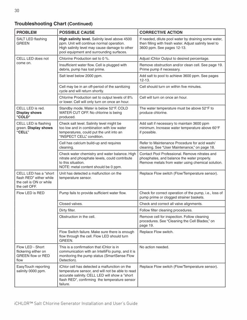
30
iCHLOR™ Salt Chlorine Generator Installation and User’s Guide
Troubleshooting Chart (Continued)
PROBLEM POSSIBLE CAUSE CORRECTIVE ACTION
SALT LED flashing GREEN
High salinity level. Salinity level above 4500 ppm. Unit will continue normal operation. High salinity level may cause damage to other pool equipment and surrounding surfaces.
If needed, dilute pool water by draining some water, then filling with fresh water. Adjust salinity level to 3600 ppm. See pages 12-13.
CELL LED does not come on.
Chlorine Production set to 0 %. Adjust iChlor Output to desired percentage.
Insufficient water flow. Cell is plugged with debris, pump has lost prime.
Remove obstruction and/or clean cell. See page 19. Prime pump if necessary.
Salt level below 2000 ppm. Add salt to pool to achieve 3600 ppm. See pages 12-13.
Cell may be in an off-period of the sanitizing cycle and will return shortly.
Cell should turn on within five minutes.
Chlorine Production set to output levels of 8% or lower. Cell will only turn on once an hour.
Cell will turn on once an hour.
CELL LED is red. Display shows "COLD"
Standby mode. Water is below 52°F. COLD WATER CUT OFF. No chlorine is being produced.
The water temperature must be above 52°F to produce chlorine.
CELL LED is flashing green. Display shows “CELL”
Check salt level. Salinity level might be too low and in combination with low water temperatures, could put the unit into an “INSPECT CELL” condition.
Add salt if necessary to maintain 3600 ppm minimum. Increase water temperature above 60°F if possible.
Cell has calcium build-up and requires cleaning.
Refer to Maintenance Procedure for acid wash/cleaning. See “User Maintenance,” on page 18.
Check water chemistry and water balance. High nitrate and phosphate levels, could contribute to this situation. NOTE: metal content should be 0 ppm.
Contact Pool Professional. Remove nitrates and phosphates, and balance the water properly. Remove metals from water using chemical solution.
CELL LED has a "short flash RED" either while the cell is ON or while the cell OFF.
Unit has detected a malfunction on the temperature sensor.
Replace Flow switch (Flow/Temperature sensor).
Flow LED is RED Pump fails to provide sufficient water flow. Check for correct operation of the pump, i.e., loss of pump prime or clogged strainer baskets.
Closed valves. Check and correct all valve alignments.
Dirty filter. Follow filter cleaning procedures.
Obstruction in the cell. Remove cell for inspection. Follow cleaning procedures. See “Cleaning the Cell Blades,” on page 19.
Flow Switch failure. Make sure there is enough flow through the cell. Flow LED should turn GREEN.
Replace Flow switch.
Flow LED - Short flickering either on GREEN flow or RED flow
This is a confirmation that iChlor is in communication with an IntelliFlo pump, and it is monitoring the pump status (SmartSense Flow Detection).
No action needed.
EasyTouch reporting salinity 0000 ppm.
iChlor cell has detected a malfunction on the temperature sensor, and will not be able to read accurate salinity. CELL LED will show a "short flash RED", confirming the temperature sensor failure.
Replace Flow switch (Flow/Temperature sensor).
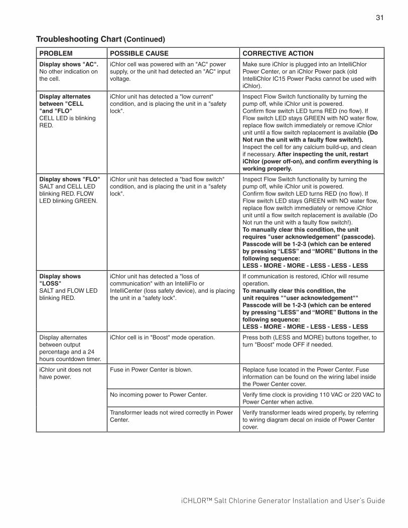
iCHLOR™ Salt Chlorine Generator Installation and User’s Guide
31
PROBLEM POSSIBLE CAUSE CORRECTIVE ACTION
Display shows "AC". No other indication on the cell.
iChlor cell was powered with an "AC" power supply, or the unit had detected an "AC" input voltage.
Make sure iChlor is plugged into an IntelliChlor Power Center, or an iChlor Power pack (old IntelliChlor IC15 Power Packs cannot be used with iChlor).
Display alternates between "CELL "and "FLO" CELL LED is blinking RED.
iChlor unit has detected a "low current" condition, and is placing the unit in a "safety lock".
Inspect Flow Switch functionality by turning the pump off, while iChlor unit is powered. Confirm flow switch LED turns RED (no flow). If Flow switch LED stays GREEN with NO water flow, replace flow switch immediately or remove iChlor unit until a flow switch replacement is available (Do Not run the unit with a faulty flow switch!). Inspect the cell for any calcium build-up, and clean if necessary. After inspecting the unit, restart iChlor (power off-on), and confirm everything is working properly.
Display shows "FLO" SALT and CELL LED blinking RED. FLOW LED blinking GREEN.
iChlor unit has detected a "bad flow switch" condition, and is placing the unit in a "safety lock".
Inspect Flow Switch functionality by turning the pump off, while iChlor unit is powered. Confirm flow switch LED turns RED (no flow). If Flow switch LED stays GREEN with NO water flow, replace flow switch immediately or remove iChlor unit until a flow switch replacement is available (Do Not run the unit with a faulty flow switch!). To manually clear this condition, the unit requires "user acknowledgement" (passcode). Passcode will be 1-2-3 (which can be entered by pressing “LESS” and “MORE” Buttons in the following sequence: LESS - MORE - MORE - LESS - LESS - LESS
Display shows "LOSS" SALT and FLOW LED blinking RED.
iChlor unit has detected a "loss of communication" with an IntelliFlo or IntelliCenter (loss safety device), and is placing the unit in a "safety lock".
If communication is restored, iChlor will resume operation. To manually clear this condition, the unit requires ""user acknowledgement"" Passcode will be 1-2-3 (which can be entered by pressing “LESS” and “MORE” Buttons in the following sequence: LESS - MORE - MORE - LESS - LESS - LESS
Display alternates between output percentage and a 24 hours countdown timer.
iChlor cell is in "Boost" mode operation. Press both (LESS and MORE) buttons together, to turn "Boost" mode OFF if needed.
iChlor unit does not have power.
Fuse in Power Center is blown. Replace fuse located in the Power Center. Fuse information can be found on the wiring label inside the Power Center cover.
No incoming power to Power Center. Verify time clock is providing 110 VAC or 220 VAC to Power Center when active.
Transformer leads not wired correctly in Power Center.
Verify transformer leads wired properly, by referring to wiring diagram decal on inside of Power Center cover.
Troubleshooting Chart (Continued)
32
iCHLOR™ Salt Chlorine Generator Installation and User’s Guide
Diagnostic ModeTo enter “Diagnostic Mode” press and hold the MORE button for 3 seconds, until light indicates you are in diagnostic mode.
Note: Be sure you are not in Output Percentage mode (Output flashing). In this mode, pressing and holding the MORE button will only fast-forward the output setting.
While in “Diagnostic Mode”, you can advance to the next screen by pressing the MORE button. You will not be able to go back to the previous screen. You can only advance by pressing the MORE button. The LESS button has different functions during diagnostic mode and will be explained further below.
There are five different screens in diagnostic mode:First screen: Total Cell Hours (life).
Displays total cell hours (lifetime) in a rotating pattern.
While on this screen, the WAND report can be displayed by pressing the LESS button.
Note: If needed, the WAND report can be re-sent by pressing the LESS button once again.
Second screen: Temperature (°F or °C)
Displays water temperature in either °F or °C.
While on this screen the user can switch between °F and °C by pressing the LESS button.
Third screen: Salinity (ppm)
Displays last salinity level (ppm) recorded by the unit.
While on this screen the unit is able to take real-time salinity readings, which can be accessed by pressing the LESS button.
Fourth screen: Cell Voltage (V)
Displays last cell voltage recorded by the unit.
While on this screen the unit is able to take real-time cell voltage readings, which can be accessed by pressing the LESS button.
Note: If front panel orientation is flipped 180° (see explanation below), displayed voltage will not show the decimal point as it shows during factory-set orientation. For example, 22.4V will be displayed as 224.
Fifth screen: Firmware Revision (r)
Displays current firmware revision (r X.XX)
While on this screen the orientation of the user interface can be flipped 180° by pressing both (LESS and MORE) output buttons. This will allow for multiple types of installations and field set ups.
Note: After flipping the user interface the button functionality will be swapped, and the display will be upside down. You will need to install a 180° overlay (included with every unit) in order to operate the unit in this mode.
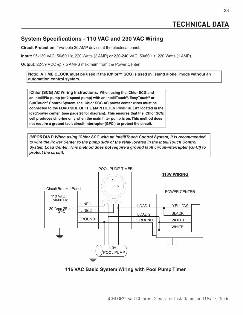
iCHLOR™ Salt Chlorine Generator Installation and User’s Guide
33
System Specifications - 110 VAC and 230 VAC Wiring
Circuit Protection: Two-pole 20 AMP device at the electrical panel.
Input: 95-130 VAC, 50/60 Hz, 220 Watts (2 AMP) or 220-240 VAC, 50/60 Hz, 220 Watts (1 AMP).
Output: 22-39 VDC @ 7.5 AMPS maximum from the Power Center.
115 VAC Basic System Wiring with Pool Pump Timer
IMPORTANT: When using iChlor SCG with an IntelliTouch Control System, it is recommended to wire the Power Center to the pump side of the relay located in the IntelliTouch Control System Load Center. This method does not require a ground fault circuit-interrupter (GFCI) to protect the circuit.
iChlor (SCG) AC Wiring Instructions: When using the iChlor SCG and an IntelliFlo pump (or 2-speed pump) with an IntelliTouch®, EasyTouch® or SunTouch® Control System, the iChlor SCG AC power center wires must be connected to the LOAD SIDE OF THE MAIN FILTER PUMP RELAY located in the load/power center (see page 28 for diagram). This ensures that the iChlor SCG cell produces chlorine only when the main filter pump is on. This method does not require a ground fault circuit-interrupter (GFCI) to protect the circuit.
Note: A TIME CLOCK must be used if the iChlor™ SCG is used in “stand alone” mode without an automation control system.
TECHNICAL DATA
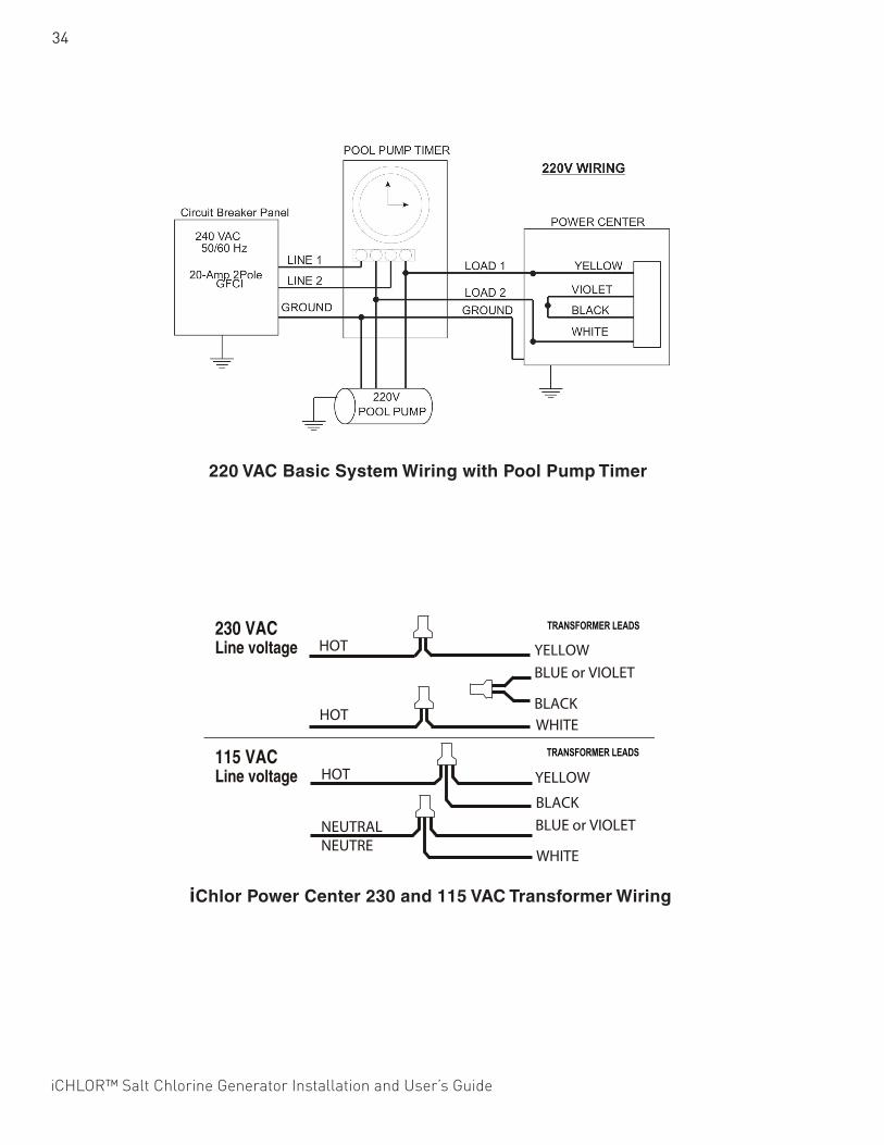
34
iCHLOR™ Salt Chlorine Generator Installation and User’s Guide
220 VAC Basic System Wiring with Pool Pump Timer
iChlor Power Center 230 and 115 VAC Transformer Wiring
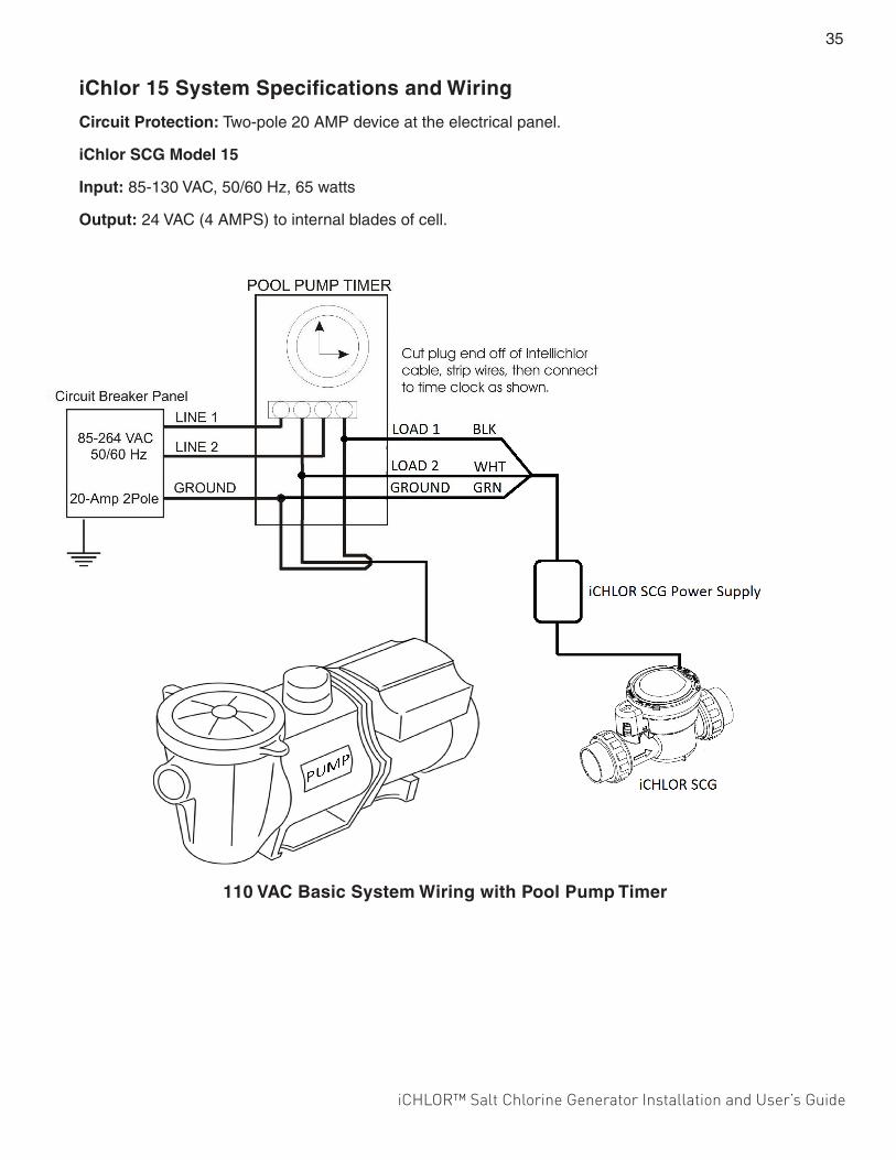
iCHLOR™ Salt Chlorine Generator Installation and User’s Guide
35
iChlor 15 System Specifications and Wiring
Circuit Protection: Two-pole 20 AMP device at the electrical panel.
iChlor SCG Model 15
Input: 85-130 VAC, 50/60 Hz, 65 watts
Output: 24 VAC (4 AMPS) to internal blades of cell.
110 VAC Basic System Wiring with Pool Pump Timer

1620 HAWKINS AVE., SANFORD, NC 27330 • (919) 566-8000 10951 WEST LOS ANGELES AVE., MOORPARK, CA 93021 • (805) 553-5000
WWW.PENTAIRPOOL.COM
All Pentair trademarks and logos are owned by Pentair or by one of its global affiliates. Pentair Aquatic Systems®, iChlor™, SunTouch®, EasyTouch®, IntelliTouch®, SmartSense™ and IntelliFlo® are trademarks and/or registered trademarks of Pentair Water Pool and Spa, Inc. and/or its affiliated companies in the United States and/ or other countries. Unless expressly noted, names and brands of third parties that may be used in this document are not used to indicate an affiliation or endorsement between the owners of these names and brands and Pentair Water Pool and Spa, Inc. Those names and brands may be the trademarks or registered trademarks of those third parties. Because we are continuously improving our products and services, Pentair reserves the right to change specifications without prior notice. Pentair is an equal opportunity employer.© 2017 Pentair Water Pool and Spa, Inc. All rights reserved. This document is subject to change without notice.
P/N 522709 Rev. B 2/21/17*522709*
SAVE THESE INSTRUCTIONS