salem, unit 1, inservice inspection (lsi) program …iddeal solutions, llc as part of the fourth...
TRANSCRIPT
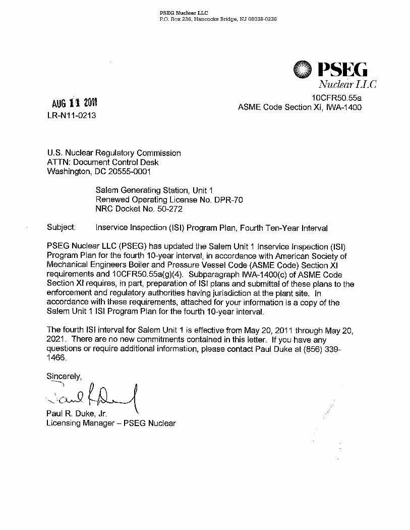
PSEG Nuclear LLC P.O. Box 236, Hancocks Bridge, NJ 08038-0236
OPSEG Nuclear LLC
AUG 11 2011 LR-N11-0213
10CFR50.55a ASME Code Section XI, IWA-1400
U.S. Nuclear Regulatory Commission ATTN: Document Control Desk Washington, DC 20555-0001
Subject:
Salem Generating Station, Unit 1 Renewed Operating License No. DPR-70 NRC Docket No. 50-272
Inservice Inspection (lSI) Program Plan, Fourth Ten-Year Interval
PSEG Nuclear LLC (PSEG) has updated the Salem Unit 1 Inservice Inspection (lSI) Program Plan for the fourth 10-year interval, in accordance with American Society of Mechanical Engineers Boiler and Pressure Vessel Code (ASME Code) Section XI requirements and 10CFR50.55a(g)(4). Subparagraph IWA-1400(c) of ASME Code Section XI requires, in part, preparation of lSI plans and submittal of these plans to the enforcement and regulatory authorities having jurisdiction at the plant site. In accordance with these requirements, attached for your information is a copy of the Salem Unit 1 lSI Program Plan for the fourth 10-year interval.
The fourth lSI interval for Salem Unit 1 is effective from May 20,2011 through May 20, 2021. There are no new commitments contained in this letter. If you have any questions or require additional information, please contact Paul Duke at (856) 339-1466.
Sincerely, --) \, __ . nPD j "'L~~~\ Paul R. Duke, Jr. Licensing Manager - PSEG Nuclear
LR~N11~0213
Page 2
Attachment
C W. Dean, Administrator, Region I, NRC R. Ennis, Project Manager - USNRC NRC Senior Resident Inspector, Salem P. Mulligan, Manager IV, NJBNE L. Marabella, Corporate Commitment Tracking Coordinator H. Berrick, Salem Commitment Tracking Coordinator
AUG 11 20ft

Salem Unit 1 ISI Program Document No.: ISI-S1-LTP4-TOC
SALEM NUCLEAR GENERATING STATION UNIT 1
ISI PROGRAM PLAN FOURTH TEN-YEAR INSPECTION INTERVAL
Commercial Service Date:
July 1, 1977
Salem Nuclear Generating Station Unit 1 Post Office Box 236
Hancocks Bridge, NJ 08038
PSEG Nuclear (PSEG), LLC P.O. Box 236
Hancocks Bridge, NJ 08038
TITLE:
lSI Program Plan Salem Unit 1 Generating Station, Fourth Interval
REVISION APPROVAL SHEET
lSI Program Plan Fourth Ten-Year Inspection Interval Salem Unit 1
DOCUMENT: ISI-S1-LTP4 REVISION: o
PREPARED TRANSMITTAL
PREPARED TRANSMITTAL
PREPARED:
Alex McNeill, Iddeal Solutions
REVIEWED:
Steve Lewis, Iddeal Solutions
APPROVED:
Kevin Hall, Iddeal Solutions
PSEG ACCEPTANCE:
roject Manager
Prepared for PSEG ii
4/28/2011
Date
4/28/2011
Date
4/29/2011
Date
D~te
ISI-S1 -L TP4·TOC Revision 0

lSI Program Plan Salem Unit 1 Generating Station, Fourth Interval
REVISION APPROVAL SHEET
TITLE:
DOCUMENT:
lSI Program Plan Fourth Ten-Year Inspection Interval Salem Unit 1
ISI-S1-L TP4
PSEG PROGRAM ACCEPTANCE
REVIEWED: ~ d~ / 6z3/ZoII Tim Giles lSI Program Owner
REVIEWED: Nt!b ... :tt /~/201j Bill Brammeier Peer Review r
APP ROVED: -Y-+-\,L-\~~~~,~",,---/ ~ Izv II Ker Colville
Salem Eng:77fo.~grams Manager REVIEWED: itII!'-~/Jt,' 'J.. /.5':.. 2 S""-/ /
HSBCT . Authorized Nuclear Inservice Inspector
REVISION: o
Each time this document is revised, the Revision Approval Sheet will be signed and the following Revision Control Sheet should be completed to provide a detailed record of the revision history. The signatures above apply only to the changes made in the revision noted. If historical signatures are required, Salem Nuclear Generating Station, Unit 1 archives should be retrieved.
Prepared for PSEG iii ISI·S1·LTP4·TOC Revision 0

ISI Program Plan Salem Unit 1 Generating Station, Fourth Interval
iv ISI-S1-LTP4-TOC Revision 0
REVISION CONTROL SHEET
Major changes to this document should be outlined within the table below. Editorial and formatting revisions are not required to be logged.
Revision Date Revision Summary
0 Initial issuance. (This ISI Program Plan was developed by IDDEAL Solutions, LLC as part of the Fourth Interval ISI Program update.)
Notes: 1. This ISI Program Plan (Sections 1 - 9 inclusive) is controlled by the Salem
Nuclear Generating Station, Unit 1, Engineering Programs Group.
2. Revision 0 of this document was issued as the Fourth Interval ISI Program Plan and was submitted to the NRC, including the initial Fourth ISI Interval Relief Requests (previously submitted for NRC approval). Future revisions of this document made within the Fourth ISI Interval will be maintained and controlled at the station; however, they are not required to be and will not be submitted to the NRC. The exception to this is that new or revised Relief Requests shall be submitted to the NRC for safety evaluation and approval.
ISI Program Plan Salem Unit 1 Generating Station, Fourth Interval
v ISI-S1-LTP4-TOC Revision 0
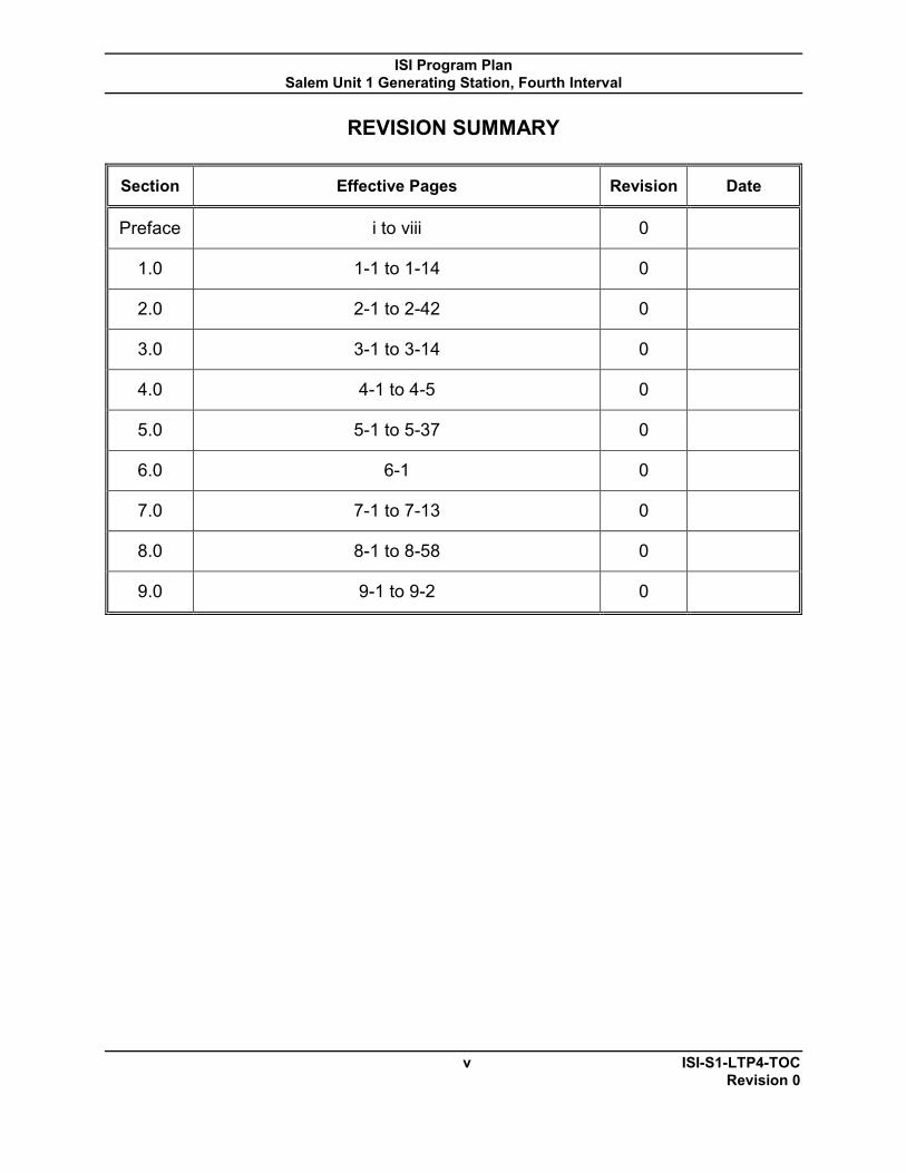
REVISION SUMMARY
Section Effective Pages Revision Date
Preface i to viii 0
1.0 1-1 to 1-14 0
2.0 2-1 to 2-42 0
3.0 3-1 to 3-14 0
4.0 4-1 to 4-5 0
5.0 5-1 to 5-37 0
6.0 6-1 0
7.0 7-1 to 7-13 0
8.0 8-1 to 8-58 0
9.0 9-1 to 9-2 0

ISI Program Plan Salem Unit 1 Generating Station, Fourth Interval
vi ISI-S1-LTP4-TOC Revision 0
TABLE OF CONTENTS SECTION DESCRIPTION PAGE 1.0 INTRODUCTION AND BACKGROUND ...................................................... 1-1
1.1 Introduction 1.2 Background 1.3 Previous ISI Programs 1.4 Fourth Interval ISI Program 1.5 Previous Interval CISI Program 1.6 Current Interval CISI Program 1.7 Code of Federal Regulations 10 CFR 50.55a Requirements 1.8 Code Cases 1.9 Relief Requests
2.0 BASIS FOR INSERVICE INSPECTION PROGRAM ................................... 2-1 2.1 ASME Section XI Examination Requirements 2.1.1 ASME Section XI Code Cases 2.2 Augmented Examination Requirements 2.3 System Classifications and P&ID Boundary Drawings 2.4 ISI Isometric and Component Drawings for Nonexempt ISI Class
Components and Supports 2.5 Technical Approach and Positions
3.0 COMPONENT ISI PLAN .............................................................................. 3-1 3.1 Nonexempt ISI Class Components 3.2 Exempt ISI Class 1 Components 3.3 Exempt ISI Class 2 Components within Residual heat Removal (RHR),
Emergency Core Cooling (ECC), and Containment Heat Removal (CHR) Systems or Portions of Systems
3.4 Exempt ISI Class 2 Components Other Than RHR, ECC, and CHR Systems or Portions of Systems
3.5 Exempt ISI Class 2 Inaccessible Welds 3.6 Exempt ISI Class 3 Components 3.7 Inspection Program B 3.8 Risk-Informed Examination Requirements 3.9 Successive Inspections 3.10 Additional Examinations
4.0 SUPPORT ISI PLAN .................................................................................... 4-1 4.1 ISI ASME Section XI Supports 4.2 Snubber Examination and Testing Requirements
5.0 SYSTEM PRESSURE TESTING ISI PLAN ................................................. 5-1 5.1 General Pressure Test Requirements 5.2 System Pressure Test Methods 5.3 System Leakage Testing 5.4 Hydrostatic Testing 5.5 Pneumatic Testing 5.6 Buried Components 5.7 Special Test Methods

ISI Program Plan Salem Unit 1 Generating Station, Fourth Interval
vii ISI-S1-LTP4-TOC Revision 0
5.8 Augmented Programs 5.9 Definitions
6.0 CONTAINMENT ISI PLAN ........................................................................... 6-1 7.0 COMPONENT SUMMARY TABLES ............................................................ 7-1
7.1 Inservice Inspection Summary Tables 8.0 RELIEF REQUESTS FROM ASME SECTION XI ........................................ 8-1 9.0 REFERENCES ............................................................................................. 9-1

ISI Program Plan Salem Unit 1 Generating Station, Fourth Interval
viii ISI-S1-LTP4-TOC Revision 0
TABLE OF CONTENTS TABLES DESCRIPTION PAGE 1.1-1 Fourth ISI Interval/Period/Outage Matrix ...................................................... 1-3 1.7-1 Code of Federal Regulations 10 CFR 50.55a Requirements ....................... 1-7 2.3-1 Salem Unit 1 Piping Specification Design Classifications .......................... 2-12 2.3-2 Salem Unit 1 Inservice Inspection Boundary Drawings .............................. 2-15 2.4-1 ISI Isometric and Component Drawings ..................................................... 2-18 2.5-1 Technical Approach and Positions Index ....................................................... 2-38 5.1 ECCS Leakage Monitoring and Reduction Program Test Procedures ....... 5-27 5.2 ECCS Leakage Monitoring and Reduction Program Test Boundaries ....... 5-29 7.1-1 Inservice Inspection Summary Table ........................................................... 7-3 7.1-2 Inservice Inspection Summary Table Program Notes ................................ 7-13 8.0-1 Relief Request Index .................................................................................... 8-3

ISI Program Plan Salem Unit 1 Generating Station, Fourth Interval
1-1 ISI-S1-LTP4-1.0 Revision 0
1.0 INTRODUCTION AND BACKGROUND
1.1 Introduction
This Inservice Inspection (ISI) Program Plan details the requirements for the examination and testing of ISI Class 1, 2, and 3 pressure retaining components and their supports at Salem Nuclear Generating Station, Unit 1 (Salem Unit 1). This ISI Program Plan also includes Risk-Informed Inservice Inspections (RI-ISI), Augmented Inservice Inspections, and Pressure Testing requirements imposed on or committed to by Salem Unit 1. At Salem Unit 1, the Inservice Testing (IST) Program is maintained and implemented separately from the ISI Program. The Salem Unit 1 Containment ISI (CISI) Plan has been separately documented and will be referenced accordingly, when necessary.
Pursuant to the Code Of Federal Regulations, Title 10, Part 50, Section 55a, Codes and standards, (10 CFR 50.55a), Paragraph (g), Inservice inspection requirements, licensees are required to update their ISI Programs to meet the requirements of ASME Section XI once every ten years or inspection interval. The ISI Program is required to comply with the latest Edition and Addenda of the Code incorporated by reference in 10 CFR 50.55a(b) twelve (12) months prior to the start of the interval per 10 CFR 50.55a(g)(4)(ii).
The Fourth ISI Interval for Salem Unit 1is effective from May 20, 2011 through May 20, 2021. The ASME Code of Record for the Fourth ISI Interval is the 2004 Edition of ASME Section XI except that Appendix VIII, its supplements, and Article I-3000 are to the 2001 Edition and Examination Category B-D, Item No. B3.120 and B3.140 are to the 1998 Edition. The ASME OM Code of Record for snubbers for the Fourth ISI Interval is the 2004 Edition.
The inspection interval may be reduced or extended by as much as one year. Adjustments shall not cause successive intervals to be altered by more than one year from the original pattern of intervals. If an inspection interval is extended, neither the start and end dates nor the inservice inspection program for the successive interval need be revised (IWA-2430(d)(1)). Examinations may be performed to satisfy the requirements of the extended interval in conjunction with examinations performed to satisfy the requirements of the successive interval. However, an examination performed to satisfy requirements of either the extended interval or the successive interval shall not be credited to both intervals (IWA-2430(d)(2)).

ISI Program Plan Salem Unit 1 Generating Station, Fourth Interval
1-2 ISI-S1-LTP4-1.0 Revision 0
The Fourth ISI Interval is divided into three inspection periods as determined by calendar years within the interval. The inspection periods may be decreased or extended by as much as 1 year to enable inspection to coincide with Salem Unit 1’s refueling outages. This adjustment shall not alter the requirements for scheduling inspection intervals (IWA-2430(d)(3)). Table 1.1-1 identifies the period start and end dates for the Fourth ISI Interval as defined by Inspection Program B.

ISI Program Plan Salem Unit 1 Generating Station, Fourth Interval
1-3 ISI-S1-LTP4-6.0 Revision 0
Table 1.1-1 Fourth ISI Interval/Period/Outage Matrix
Interval Periods Outages
Start Date to
End Date
Start Date to
End Date
Outage and/or
Durations
Outage Numbers
Fourth ISI Interval
05/20/11
to 05/20/21
1st 05/20/11 to 05/20/14
Fall 2011
24 days RF21
Spring 2013
27 days RF22
2nd 05/20/14 to 05/20/18
Fall 2014
27 days RF23
Spring 2016
28 days RF24
Fall 2017
22 days RF25
3rd 05/20/18 to 05/20/21
Spring 2019
24 days RF26
Fall 2020
29 days RF27

ISI Program Plan Salem Unit 1 Generating Station, Fourth Interval
1-4 ISI-S1-LTP4-1.0 Revision 0
1.2 Background
Salem Unit 1 is a Westinghouse four-loop pressurized water reactor (PWR) with an electrical output of approximately 1174 MWe and located at Hancocks Bridge, NJ. Salem Unit 1 obtained construction permit CPPR-52 to build Salem Unit 1 on September 25, 1968. The docket number assigned to Salem Unit 1 is 50-272. After satisfactory plant construction and preoperational testing was completed, Salem Unit 1 was granted a full power operating license, DPR-70. Salem Unit 1 commenced commercial operation on July 1, 1977.
Salem Unit 1’s piping systems and associated components were designed and fabricated to allow the PSI/ISI examination requirements of the ASME Section XI, 1971 Edition with Addenda through the Winter of 1972 (except where specific guidance was otherwise provided by PSEG). Although this plant met the requirements of this early version of ASME Section XI, literal compliance may not be feasible or practical within the limits of the current plant design for later editions and addenda of ASME Section XI. Certain limitations are likely to occur due to conditions such as accessibility, geometric configuration, and/or metallurgical characteristics. For some inspection categories, an alternate component may be selected, based upon similar access, geometric configuration, metallurgical issues, or separate radiological concerns, for examination, and still allow the Code statistical and distribution requirements to be maintained. If Code required examination criteria cannot be met, a relief request will be submitted in accordance with 10 CFR 50.55a for examination limitations.
1.3 Previous ISI Programs
1.3.1 First Interval ISI Program
On July 1, 1977, Salem Unit 1 began commercial operation, beginning the first inspection interval. The Inservice Inspection Program was developed to implement the requirements of the ASME Boiler and Pressure Vessel Code (ASME Code), Section XI, 1974 Edition with Addenda through the Summer 1975, and supplemented with NRC approved Code Cases.
The first inspection interval for Salem Unit 1 ended on February 27, 1988. The interval was extended 7 months and 16 days per IWA-2400 [74S75] to coincide with the end of a refueling outage.
1.3.2 Second Interval ISI Program
The second inspection interval commenced on February 27, 1988. The ISI Program utilized the ASME Code, Section XI, 1983 Edition through the

ISI Program Plan Salem Unit 1 Generating Station, Fourth Interval
1-5 ISI-S1-LTP4-1.0 Revision 0
Summer 1983 Addenda, and supplemented with NRC approved Code Cases.
The second inspection interval ended on May 19, 2001. The interval was extended 36 months and 10 days (4/7/95 – 4/17/98) for an extended shutdown and 2 months and 13 days to coincide with the end of a refueling outage per IWA-2400(c) [83/83]. The cumulative interval extension per IWA-2412 is currently approximately 10 months (maximum extension is 12 months).
1.3.3 Third Interval ISI Program
The third inspection interval commenced on May 20, 2001. The ISI Program was developed utilizing the ASME Code, Section XI, 1995 Edition through the 1996 Addenda and supplemented with NRC approved Code Cases. In 2003 prior to the 2nd outage of the 1st period of the 3rd ISI Ten Year interval, Salem Unit 1 incorporated RI-ISI and upgraded to ASME Code, Section XI, 1998 Edition through the 2000 Addenda.
The third inspection interval ends on May 20, 2011.
1.4 Fourth Interval ISI Program
The Fourth ISI Interval will commence on May 20, 2011. The Salem Unit 1 Fourth Interval ISI Program Plan was developed in accordance with the requirements of the 2004 Edition of ASME Section XI the Code of Record as required by 10 CFR 50.55a(g)(4)(ii), subject to the limitations and modifications contained within Paragraph (b) of the regulation. These limitations and modifications are detailed in Table 1.7-1 of this section. This ISI Program Plan is limited to Subsections IWA, IWB, IWC, IWD, IWF, Mandatory Appendices, approved ASME Code Cases, approved alternatives through relief requests and SER’s, and utilizes Inspection Program B of the ASME Code, Section XI.
Salem Unit 1 previously adopted the EPRI Topical Report TR-112657, Rev. B-A methodology, which was supplemented by Code Case N-578-1, for implementing risk-informed inservice inspections. The RI-ISI Program will be in effect for the entire Fourth ISI Interval. This approach replaces the categorization, selection, and examination volume requirements of ASME Section XI Examination Categories B-F, B-J, C-F-1, and C-F-2 applicable to Salem Unit 1 with Examination Category R-A as defined in Code Case N-578-1. Implementation of RI-ISI Program is in accordance with Relief Request S1-I4R-105.
Salem Unit 1 has also adopted the EPRI Topical Report TR-1006937, Rev. 0-A, methodology for additional guidance for adaptation of the RI-ISI
ISI Program Plan Salem Unit 1 Generating Station, Fourth Interval
1-6 ISI-S1-LTP4-1.0 Revision 0
evaluation process to Break Exclusion Region (BER) piping, also referred to as the High Energy Line Break (HELB) region. The BER program is an augmented program outside the scope of 10 CFR 50.55a and Section XI, therefore this change was made under the provisions of 10 CFR 50.59. The BER program will be in effect for the entire Fourth ISI Interval.
1.5 Previous Interval (1st) CISI Program
The CISI Program previous interval information is documented in ISI-S1-LTP1.
1.6 Current Interval (2nd) CISI Program
The CISI Program current interval information is documented in CISI-SC-LTP2.
1.7 Code of Federal Regulations 10 CFR 50.55a Requirements
There are certain paragraphs in 10 CFR 50.55a that list the limitations, modifications, and/or clarifications to the implementation requirements of ASME Section XI. These paragraphs in 10 CFR 50.55a that are applicable to the Salem Unit 1 scheduled ISI examination programs are detailed in Table 1.7-1. Limitations applicable to the scheduled CISI examination programs are documented in CISI-SC-LTP2.

ISI Program Plan Salem Unit 1 Generating Station, Fourth Interval
1-7 ISI-S1-LTP4-1.0 Revision 0
TABLE 1.7-1 CODE OF FEDERAL REGULATIONS 10 CFR 50.55a REQUIREMENTS
10 CFR 50.55a Paragraphs
Limitations, Modifications, and Clarifications
10 CFR 50.55a(b)(2)(iii) Steam generator tubing (modifies Article IWB- 2000). If the technical specifications of a nuclear power plant include surveillance requirements for steam generators different than those in Article IWB- 2000, the inservice inspection program for steam generator tubing is governed by the requirements in the technical specifications.
10 CFR 50.55a(b)(2)(x) Quality Assurance. When applying Section XI editions and addenda later than the 1989 Edition, the requirements of NQA-1, "Quality Assurance Requirements for Nuclear Facilities," 1979 Addenda through the 1989 Edition, are acceptable as permitted by IWA-1400 of Section XI, if the licensee uses its 10 CFR Part 50, Appendix B, quality assurance program, in conjunction with Section XI requirements. Commitments contained in the licensee's quality assurance program description that are more stringent than those contained in NQA-1 must govern Section XI activities. Further, where NQA-1 and Section XI do not address the commitments contained in the licensee's Appendix B quality assurance program description, the commitments must be applied to Section XI activities.
10 CFR 50.55a(b)(2)(xii) Underwater Welding. The provisions in IWA-4660, "Underwater Welding," of Section XI, 1997 Addenda through the latest edition and addenda incorporated by reference in paragraph (b)(2) of this section, are not approved for use on irradiated material.
10 CFR 50.55a(b)(2)(xiv) Appendix VIII personnel qualification. All personnel qualified for performing ultrasonic examinations in accordance with Appendix VIII shall receive 8 hours of annual hands-on training on specimens that contain cracks. Licensees applying the 1999 Addenda through the latest edition and addenda incorporated by reference in paragraph (b)(2) of this section may use the annual practice requirements in VII-4240 of Appendix VII of Section XI in place of the 8 hours of annual hands-on training provided that the supplemental practice is performed on material or welds that contain cracks, or by analyzing prerecorded data from material or welds that contain cracks. In either case, training must be completed no earlier than 6 months prior to performing ultrasonic examinations at a licensee's facility.

ISI Program Plan Salem Unit 1 Generating Station, Fourth Interval
1-8 ISI-S1-LTP4-1.0 Revision 0
TABLE 1.7-1 CODE OF FEDERAL REGULATIONS 10 CFR 50.55a REQUIREMENTS
10 CFR 50.55a Paragraphs
Limitations, Modifications, and Clarifications
10 CFR 50.55a(b)(2)(xv) Appendix VIII specimen set and qualification requirements. The following provisions may be used to modify implementation of Appendix VIII of Section XI, 1995 Edition through the 2001 Edition. Licensees choosing to apply these provisions shall apply all of the following provisions under this paragraph except for those in § 50.55a(b)(2)(xv)(F) which are optional. Licensees who use later editions and addenda than the 2001 Edition of the ASME Code shall use the 2001 Edition of Appendix VIII. [Provisions not listed in this table, refer to regulation for provisions.]
10 CFR 50.55a(b)(2)(xvi) Appendix VIII single side ferritic vessel and piping and stainless steel piping examination. (A) Examinations performed from one side of a ferritic vessel weld must be conducted with equipment, procedures, and personnel that have demonstrated proficiency with single side examinations. To demonstrate equivalency to two sided examinations, the demonstration must be performed to the requirements of Appendix VIII as modified by this paragraph and §§ 50.55a(b)(2)(xv) (B) through (G), on specimens containing flaws with non-optimum sound energy reflecting characteristics or flaws similar to those in the vessel being examined. (B) Examinations performed from one side of a ferritic or stainless steel pipe weld must be conducted with equipment, procedures, and personnel that have demonstrated proficiency with single side examinations. To demonstrate equivalency to two sided examinations, the demonstration must be performed to the requirements of Appendix VIII as modified by this paragraph and § 50.55a(b)(2)(xv)(A).
10 CFR 50.55a(b)(2)(xviii) Certification of NDE personnel. (A) Level I and II nondestructive examination personnel shall be recertified on a 3-year interval in lieu of the 5-year interval specified in the 1997 Addenda and 1998 Edition of IWA-2314, and IWA-2314(a) and IWA-2314(b) of the 1999 Addenda through the latest edition and addenda incorporated by reference in paragraph (b)(2) of this section. (B) Paragraph IWA-2316 of the 1998 Edition through the latest edition and addenda incorporated by reference in paragraph (b)(2) of this section, may only be used to qualify

ISI Program Plan Salem Unit 1 Generating Station, Fourth Interval
1-9 ISI-S1-LTP4-1.0 Revision 0
TABLE 1.7-1 CODE OF FEDERAL REGULATIONS 10 CFR 50.55a REQUIREMENTS
10 CFR 50.55a Paragraphs
Limitations, Modifications, and Clarifications
personnel that observe for leakage during system leakage and hydrostatic tests conducted in accordance with IWA-5211(a) and (b), 1998 Edition through the latest edition and addenda incorporated by reference in paragraph (b)(2) of this section.
(C) When qualifying visual examination personnel for VT-3 visual examinations under paragraph IWA-2317 of the 1998 Edition through the latest edition and addenda incorporated by reference in paragraph (b)(2) of this section, the proficiency of the training must be demonstrated by administering an initial qualification examination and administering subsequent examinations on a 3-year interval.
10 CFR 50.55a(b)(2)(xix)
Substitution of alternative methods. The provisions for the substitution of alternative examination methods, a combination of methods, or newly developed techniques in the 1997 Addenda of IWA-2240 must be applied. The provisions in IWA-2240, 1998 Edition through the latest edition and addenda incorporated by reference in paragraph (b)(2) of this section, are not approved for use. The provisions in IWA-4520(c), 1997 Addenda through the latest edition and addenda incorporated by reference in paragraph (b)(2) of this section, allowing the substitution of alternative examination methods, a combination of methods, or newly developed techniques for the methods specified in the Construction Code are not approved for use.
10 CFR 50.55a(b)(2)(xx)
System leakage tests. (B) The NDE provision in IWA- 4540(a)(2) of the 2002 Addenda of Section XI must be applied when performing system leakage tests after repair and replacement activities performed by welding or brazing on a pressure retaining boundary using the 2003 Addenda through the latest edition and addenda incorporated by reference in paragraph (b)(2) of this section.
10 CFR 50.55a(b)(2)(xxi)
Table IWB-2500-1 examination requirements. (A) The provisions of Table IWB-2500-1, Examination Category B-D, Full Penetration Welded Nozzles in Vessels, Items B3.40 and B3.60 (Inspection Program A) and Items B3.120 and B3.140 (Inspection Program B) of the 1998 Edition must be applied when using the 1999 Addenda through the latest edition and addenda incorporated by reference in paragraph (b)(2) of this section. A visual

ISI Program Plan Salem Unit 1 Generating Station, Fourth Interval
1-10 ISI-S1-LTP4-1.0 Revision 0
TABLE 1.7-1 CODE OF FEDERAL REGULATIONS 10 CFR 50.55a REQUIREMENTS
10 CFR 50.55a Paragraphs
Limitations, Modifications, and Clarifications
examination with magnification that has a resolution sensitivity to detect a 1-mil width wire or crack, utilizing the allowable flaw length criteria in Table IWB-3512-1, 1997 Addenda through the latest edition and addenda incorporated by reference in paragraph (b)(2) of this section, with a limiting assumption on the flaw aspect ratio (i.e., a/l=0.5), may be performed instead of an ultrasonic examination. (B) The provisions of Table IWB-2500-1, Examination Category B-G-2, Item B7.80, that are in the 1995 Edition are applicable only to reused bolting when using the 1997 Addenda through the latest edition and addenda incorporated by reference in paragraph (b)(2) of this section.
10 CFR 50.55a(b)(2)(xxii)
Surface Examination. The use of the provision in IWA-2220, "Surface Examination," of Section XI, 2001 Edition through the latest edition and addenda incorporated by reference in paragraph (b)(2) of this section, that allow use of an ultrasonic examination method is prohibited.
10 CFR 50.55a(b)(2)(xxiii)
Evaluation of Thermally Cut Surfaces. The use of the provisions for eliminating mechanical processing of thermally cut surfaces in IWA-4461.4.2 of Section XI, 2001 Edition through the latest edition and addenda incorporated by reference in paragraph (b)(2) of this section are prohibited.
10 CFR 50.55a(b)(2)(xxiv)
Incorporation of the Performance Demonstration Initiative and Addition of Ultrasonic Examination Criteria. The use of Appendix VIII and the supplements to Appendix VIII and Article I-3000 of Section XI of the ASME BPV Code, 2002 Addenda through the latest edition and addenda incorporated by reference in paragraph (b)(2) of this section, is prohibited.
10 CFR 50.55a(b)(2)(xxv)
Mitigation of Defects by Modification. The use of the provisions in IWA-4340, "Mitigation of Defects by Modification," Section XI, 2001 Edition through the latest edition and addenda incorporated by reference in paragraph (b)(2) of this section are prohibited.
10 CFR 50.55a(b)(2)(xxvi)
Pressure Testing Class 1, 2, and 3 Mechanical Joints. The repair and replacement activity provisions in IWA-4540(c) of the 1998 Edition of Section XI for pressure testing Class 1, 2, and 3 mechanical joints must be applied when using the 2001 Edition through the latest edition and addenda incorporated by reference in paragraph (b)(2) of this section.

ISI Program Plan Salem Unit 1 Generating Station, Fourth Interval
1-11 ISI-S1-LTP4-1.0 Revision 0
TABLE 1.7-1 CODE OF FEDERAL REGULATIONS 10 CFR 50.55a REQUIREMENTS
10 CFR 50.55a Paragraphs
Limitations, Modifications, and Clarifications
10 CFR 50.55a(b)(2)(xxvii) Removal of Insulation. When performing visual examinations in accordance with IWA-5242 of Section XI, 2003 Addenda through the latest edition and addenda incorporated by reference in paragraph (b)(2) of the section, insulation must be removed from 17-4 PH or 410 stainless steel studs or bolts aged at a temperature below 1100 °F or having a Rockwell Method C hardness value above 30, and from A-286 stainless steel studs or bolts preloaded to 100,000 pounds per square inch or higher.
10 CFR 50.55a(b)(3)(i) Quality Assurance. When applying editions and addenda of the OM Code, the requirements of NQA-1, "Quality Assurance Requirements for Nuclear Facilities," 1979 Addenda, are acceptable as permitted by ISTA 1.4 of the 1995 Edition through 1997 Addenda or ISTA-1500 of the 1998 Edition through the latest edition and addenda incorporated by reference in paragraph (b)(3) of this section, provided the licensee uses its 10 CFR Part 50, Appendix B, quality assurance program in conjunction with the OM Code requirements. Commitments contained in the licensee's quality assurance program description that are more stringent than those contained in NQA-1 govern OM Code activities. If NQA-1 and the OM Code do not address the commitments contained in the licensee's Appendix B quality assurance program description, the commitments must be applied to OM Code activities.
10 CFR 50.55a(b)(3)(v) Subsection ISTD. Article IWF-5000, "Inservice Inspection Requirements for Snubbers," of the ASME BPV Code, Section XI, provides inservice inspection requirements for examinations and tests of snubbers at nuclear power plants. Licensees may use Subsection ISTD, "Inservice Testing of Dynamic Restraints (Snubbers) in Light-Water Reactor Power Plants," ASME OM Code, 1995 Edition through the latest edition and addenda incorporated by reference in paragraph (b)(3) of this section, in place of the requirements for snubbers in Section XI, IWF-5200(a) and (b) and IWF-5300(a) and (b), by making appropriate changes to their technical specifications or licensee-controlled documents. Preservice and inservice examinations must be performed using the VT-3 visual examination method described in IWA-2213.
10 CFR 50.55a(b)(5) Inservice Inspection Code Cases: Licensees may apply the ASME Boiler and Pressure Vessel Code Cases listed in

ISI Program Plan Salem Unit 1 Generating Station, Fourth Interval
1-12 ISI-S1-LTP4-1.0 Revision 0
TABLE 1.7-1 CODE OF FEDERAL REGULATIONS 10 CFR 50.55a REQUIREMENTS
10 CFR 50.55a Paragraphs
Limitations, Modifications, and Clarifications
Regulatory Guide 1.147 through Revision 16, without prior NRC approval subject to the following: (i) When a licensee initially applies a listed Code Case, the licensee shall apply the most recent version of that Code Case incorporated by reference in this paragraph. (ii) If a licensee has previously applied a Code Case and a later version of the Code Case is incorporated by reference in this paragraph, the licensee may continue to apply, to the end of the current 120-month interval, the previous version of the Code Case as authorized or may apply the later version of the Code Case, including any NRC-specified conditions placed on its use. (iii) Application of an annulled Code Case is prohibited unless a licensee previously applied the listed Code Case prior to it being listed as annulled in Regulatory Guide 1.147. Any Code Case listed as annulled in any Revision of Regulatory Guide 1.147 which a licensee has applied prior to it being listed as annulled, may continue to be applied by that licensee to the end of the 120-month interval in which the Code Case was implemented.
10 CFR 50.55a(b)(6) (ISI) Operation and Maintenance of Nuclear Power Plants Code Cases. Licensees may apply the ASME Operation and Maintenance Nuclear Power Plants Code Cases listed in Regulatory Guide 1.192 without prior NRC approval subject to the following: (i) When a licensee initially applies a listed Code Case, the licensee shall apply the most recent version of that Code Case incorporated by reference in this paragraph. (ii) If a licensee has previously applied a Code Case and a later version of the Code Case is incorporated by reference in this paragraph, the licensee may continue to apply, to the end of the current 120-month interval, the previous version of the Code Case as authorized or may apply the later version of the Code Case, including any NRC-specified conditions placed on its use. (iii) Application of an annulled Code Case is prohibited unless a licensee previously applied the listed Code Case prior to it being listed as annulled in Regulatory Guide 1.192. If a licensee has applied a listed Code Case that is later listed as annulled in Regulatory Guide 1.192, the licensee may continue to apply the Code Case to the end of the current 120-month interval.
ISI Program Plan Salem Unit 1 Generating Station, Fourth Interval
1-13 ISI-S1-LTP4-1.0 Revision 0
1.8 Code Cases
In accordance with 10 CFR 50.55a(b)(5), and (b)(6), ASME Code Cases that have been determined to be suitable for use in ISI Program Plans by the NRC are listed in Regulatory Guide 1.147, "Inservice Inspection Code Case Acceptability-ASME Section XI, Division 1". The approved Code Cases in Regulatory Guide 1.147, which are being utilized by Salem Unit 1, are included in Section 2.1.1. The most recent version of a given Code Case incorporated in the revision of Regulatory Guide 1.147 referenced in 10 CFR 50.55a(b)(5)(i) at the time it is applied within the ISI Program shall be used. The latest version of Regulatory Guide 1.147 incorporated into this document is Revision 16. As this guide is revised, newly approved Code Cases will be assessed for plan implementation at Salem Unit 1.
The use of Code Cases, other than those listed in Regulatory Guide 1.147 may be authorized by the Director of the office of Nuclear Reactor Regulation upon request pursuant to 10 CFR 50.55a(a)(3). Code Cases not generically approved for use in Regulatory Guide 1.147, which are being utilized by Salem Unit 1 through associated relief requests, are included in Section 8.0.
This ISI Program Plan will also utilize Regulatory Guide 1.192, “Operation and Maintenance Code Case Acceptability, ASME OM Code”. The approved Code Cases in Regulatory Guide 1.192, which are being utilized by Salem Unit 1, are included in Section 2.1.2. The latest version of Regulatory Guide 1.192 incorporated into this document is Revision 0. As this guide is revised, newly approved Code Cases will be assessed for plan implementation at Salem Unit 1.
1.9 Relief Requests
In accordance with 10 CFR 50.55a, when a licensee either proposes alternatives to ASME Section XI requirements which provide an acceptable level of quality and safety, determines compliance with ASME Section XI requirements would result in hardship or unusual difficulty without a compensating increase in the level of quality and safety, or determines that specific ASME Section XI requirements for inservice inspection are impractical, the licensee shall notify the NRC and submit information to support the determination.
The submittal of this information will be referred to in this document as a "relief request.” Relief requests for the Fourth ISI Interval are included in Section 8.0 of this document. The text of the relief requests contained in Section 8.0 will demonstrate one of the following: the proposed alternatives provide an acceptable level of quality and safety per

ISI Program Plan Salem Unit 1 Generating Station, Fourth Interval
1-14 ISI-S1-LTP4-1.0 Revision 0
10 CFR 50.55a(a)(3)(i), compliance with the specified requirements would result in hardship or unusual difficulty without a compensating increase in the level of quality and safety per 10 CFR 50.55a(a)(3)(ii), or the code requirements are considered impractical per 10 CFR 50.55a(g)(5)(iii).
Per 10 CFR 50.55a Paragraph (g)(6)(i), the Director of the Office of Nuclear Reactor Regulation will evaluate relief requests and "may grant such relief and may impose such alternative requirements as it determines is authorized by law and will not endanger life or property or the common defense and security and is otherwise in the public interest giving due consideration to the burden upon the licensee that could result if the requirements were imposed on the facility.”

lSI Program Plan Salem Unit 1 Generating Station, Fourth Interval
2.0 BASIS FOR INSERVICE INSPECTION PROGRAM
2.1 ASME Section XI Examination Requirements
As required by the 10 CFR 50.55a, this Program was developed in accordance with the requirements detailed in the 2004 Edition, of the ASME Boiler and Pressure Vessel Code, Section XI, Division 1, Subsections IWA, IWB, IWC, IWD, IWF, Mandatory Appendices,
-- -----:lnspeeti()fl-i=>f()gram~B=of=IWA~2432,-=approved::ASM~-eQde=easss~aRd------ ---------- -approved alternatives through relief requests and Safety Evaluation Reports (SER's).
The lSI Program implements Appendix VIII "Performance Demonstration for Ultrasonic Examination Systems," and Article 1-3000 of ASME Section XI 2001 Edition as required by 10 CFR 50.S5a(b)(2)(xxiv). AppendixVl1i requires qualification of the procedures, personnel, and equipment used to detect and size flaws in piping, bolting, and specific welds of the reactor pressure vessel (RPV). Each organization (e.g., owner or vendor) is required to have a written program to ensure compliance with the requirements. The organization may contract implementation of the program. Salem Unit 1 initially implemented these requirements by invoking the Performance Demonstration Initiative (PDI) Program. The supplements of Appendix VIII are met according to the schedule defined in 10 CFR SO.55a(g)(6)(ii)(C).
For the Fourth lSI Interval, Salem Unit 1 IS inspection program for ASME Section XI Examination Categories B-F, B-J, C-F-1, and C-F-2 will be governed by risk-informed regulations. The RI-ISI program methodology is described in the EPRI Topical Report TR-112657, Rev. B-A. To supplement the EPRI Topical Report, Code Case N-S78-1 (as applicable per Relief Request S 1-14R-1 05) is also being used for the classification of piping structural elements under the RI-ISI program. The RI-ISI program scope has been implemented as an alternative to the 2004 Edition of the ASME Section XI Code examination program for Class 1 B-F and B-J welds and Class 2 C-F-1 and C-F-2 welds in accordance with 10 CFR SO.SSa(a)(3)(i). The basis for the resulting Risk Categorizations of the nonexempt Class 1 and 2 piping systems at Salem Unit 1 is defined and maintained in the lSI Selection Document.
Additionally for the Fourth lSI Interval, high energy piping outside containment commonly referred to by the industry as HELB or BER piping will make use of EPRI RI-BER technology. The BER program methodology is described in EPRI Topical Report TR-1006937, Rev. O-A, which has been used to define the inspection scope.
2-1 ISI~S1-L TP4-2.0 Revision 0

151 Program Plan Salem Unit 1 Generating Station, Fourth Interval
2.1.1 ASME Section XI Code Cases
As referenced by 10 CFR 50.55a(b)(5) and allowed by USNRC Regulatory Guide 1.147, Revision 16, the following Code Cases are being incorporated into the Salem Unit 1 lSI Program.
N-432-1 Repair Welding Using Automatic or Machine Gas Tungsten-Arc Welding (GTAW) Temper Bead
-------------------T"eehniqu8,---::-::::c-=:-==:-::-:===== ------- - -----
N-460
N-516-3
N-517-1
N-526
N-532-4
N-552
Alternative Examination Coverage for Class 1 and Class 2 Welds
Underwater Welding
Code Case N-516-3 is acceptable subject to the following condition specified in Regulatory Guide 1.147, Revision 16:
Licensees must obtain NRC approval in accordance with 10 CFR 50.55a(a)(3) regarding the technique to be used in the weld repair or replacement of irradiated material underwater.
Quality Assurance Program Requirements for Owners
Alternative Requirements for Successive Inspections of Class 1 and 2 Vessels
Alternative Requirements to Repair and Replacement Documentation Requirements and Inservice Summary Report Preparation and Submission as Required by IWA-4000 and IWA-6000
Alternative Methods - Qualification for Nozzle Inside Radius Section from the Outside Surface
Code Case N-552 is acceptable subject to the following conditions specified in Regulatory Guide 1.147, Revision 16:
To achieve consistency with the 10 CFR 50.55a rule change published September 22, 1999 (64 FR 51370), incorporating Appendix VIII, "Performance Demonstration for Ultrasonic Examination Systems," to ASME Section XI, add the following to the specimen requirements:
2-2 Revision 0

151 Program Plan Salem Unit 1 Generating Station, Fourth Interval
N-566-2
N-578-1
N-586-1
N-597-2
"At least 50 percent of the flaws in the demonstration test set must be cracks and the maximum misorientation must be demonstrated with cracks. Flaws in nozzles with bore diameters equal to or less than 4 inches may be notches."
Add to detection criteria, "The number of false calls must not exceed three."
Corrective Action for Leakage Identified at Bolted Connections
Risk-Informed Requirements for Class 1, 2, and 3 Piping, Method B (Relief request to implement required)
Alternative Additional Examination Requirements for Class 1, 2, and 3 Piping, Components, and Supports
Requirements for Analytical Evaluation of Pipe Wall Thinning
Code Case N-597 -2 is acceptable subject to the following conditions specified in Regulatory Guide 1.147, Revision 16:
(1) Code Case must be supplemented by the provisions of EPRI Nuclear Safety Analysis Center Report 202L-R2,"Recommendations for an Effective Flow Accelerated Corrosion Program" (Ref. 6), April 1999, for developing the inspection requirements, the method of predicting the rate of wall thickness loss, and the value of the predicted remaining wall thickness. As used in NSAC-202L- 2, the term "should" is to be applied as "shall" (Le., a requirement).
(2) Components affected by flow-accelerated corrosion to which this Code Case are applied must be repaired or replaced in accordance with the construction code of record and Owner's requirements or a later NRC approved edition of Section III, "Rules for Construction of Nuclear Power Plant Components," of the ASME Code (Ref. 7) prior to the value of tp reaching the allowable minimum wall
2-3 ISI-S1-LTP4-2.0 Revision 0

ISI Program Plan Salem Unit 1 Generating Station, Fourth Interval
2-4 ISI-S1-LTP4-2.0 Revision 0
thickness, tmin, as specified in - 3622.1(a)(1) of this Code Case. Alternatively, use of the Code Case is subject to NRC review and approval per 10 CFR 50.55a(a)(3).
(3) For Class 1 piping not meeting the criteria of - 221, the use of evaluation methods and criteria is subject to NRC review and approval per 10 CFR 50.55a(a)(3).
(4) For those components that do not require immediate repair or replacement, the rate of wall thickness loss is to be used to determine a suitable inspection frequency so that repair or replacement occurs prior to reaching allowable minimum wall thickness, tmin.
(5) For corrosion phenomenon other than flow accelerated corrosion, use of the Code Case is subject to NRC review and approval. Inspection plans and wall thinning rates may be difficult to justify for certain degradation mechanisms such as MIC and pitting.
N-600 Transfer of Welder, Welding Operator, Brazer, and
Brazing Operator Qualifications Between Owners
N-624 Successive Inspections
N-639 Alternative Calibration Block Material
Code Case N-639 is acceptable subject to the following conditions specified in Regulatory Guide 1.147, Revision 16:
Chemical ranges of the calibration block may vary from the materials specification if (1) it is within the chemical range of the component specification to be inspected, and (2) the phase and grain shape are maintained in the same ranges produced by the thermal process required by the material specification.
N-648-1 Alternative Requirements for Inner Radius Examination of Class 1 Reactor Vessel Nozzles
Code Case N-648-1 is acceptable subject to the following conditions specified in Regulatory Guide 1.147, Revision 16:

ISI Program Plan Salem Unit 1 Generating Station, Fourth Interval
2-5 ISI-S1-LTP4-2.0 Revision 0
In place of a UT examination, licensees may perform a visual examination with enhanced magnification that has a resolution sensitivity to detect a 1-mil width wire or crack, utilizing the allowable flaw length criteria of Table IWB-3512-1 with limiting assumptions on the flaw aspect ratio. The provisions of Table IWB-2500-1, Examination Category B-D, continue to apply except that, in place of examination volumes, the surfaces to be examined are the external surfaces shown in the figures applicable to this table (the external surface is from point M to point N in the figure).
N-686-1 Alternative Requirements for Visual Examinations, VT-1, VT-2, and VT-3
N-706-1 Alternative Examination Requirements of Table IWB-2500-1 and Table IWC-2500-1 for PWR Stainless Steel Residual and Regenerative Heat Exchangers
N-722 Additional Examinations for PWR Pressure Retaining Welds in Class 1 Components Fabricated with Alloy 600/82/182 Materials
Code Case N-722 is mandated by 10 CFR 50.55a(g)(6)(ii)(E)(1) with multiple conditions. (This is an augmented program at Salem.)
N-729-1 Alternate Examination Requirements for PWR Reactor Vessel Upper Heads with Nozzles Having Pressure-Retaining Partial-Penetration Welds
Code Case N-729-1 is mandated by 10 CFR 50.55a(g)(6)(ii)(D)(1) with multiple conditions. (This is an augmented program at Salem.)
N-731 Alternative Class 1 System Leakage Test Pressure Requirements
N-735 Successive Inspections of Class 1 and 2 Piping Welds
N-753 Vision Tests

ISI Program Plan Salem Unit 1 Generating Station, Fourth Interval
2-6 ISI-S1-LTP4-2.0 Revision 0
Additional Code Cases invoked in the future shall be in accordance with those approved for use in the latest published revision of Regulatory Guide 1.147 at that time.
2.1.2 O&M Code Cases (ISTD – Snubbers)
Currently there are no Code Cases associated with the ISTD snubber program adopted by the Salem Unit 1 program. Additional Code Cases invoked in the future shall be in accordance with those approved for use in the latest published revision of Regulatory Guide 1.192 at that time. Code Cases, if adopted for the ISTD program, will be recorded in the ISTD Program Plan.
2.2 Augmented Examination Requirements
Augmented examination requirements are those examinations that are performed above and beyond the requirements of ASME Section XI. Below is a summary of augmented examinations performed by Salem Unit 1 for the fourth inspection interval. Changes to these programs are not addressed by 10 CFR 50.55a, but through other means such as 10 CFR 50.59. As such, general Code requirements such as the ANII are not followed unless specifically identified in the augmented program.
Although listed in this section, Code Cases N-722 and N-729-1 are an exception and are considered expedited Code requirements required by 10 CFR 50.55a; falling under that regulation and the general Code requirements including the ANII.
2.2.1 NUREG-0578
PSEG committed to perform an examination to reduce potential and existing leakage paths from systems outside containment that would or could contain radioactive fluids during a serious transient or accident for the Residual Heat Removal, Safety Injection, Containment Spray, Chemical Volume and Control, Waste Gas, Waste Liquid, and Sampling Systems. The NUREG-0578 program consists of integrated leak test of these systems. At intervals not to exceed each refueling outage, an operating pressure leak test will be performed on portions of the Safety Injection, Residual Heat Removal, Chemical and Volume Control, Reactor Coolant Sampling, Liquid Radwaste, Gaseous Radwaste and Containment Spray Systems. The pressurized system will be visually inspected for leakage into building environment. Any observed leakage will be corrected to the extent reasonably practical. Where, feasible, leakage from liquid containing systems will be determined by
ISI Program Plan Salem Unit 1 Generating Station, Fourth Interval
2-7 ISI-S1-LTP4-2.0 Revision 0
counting the number of drops from each system. Section 5, Attachment 3, provides details for this program.
2.2.2 Regulatory Guide 1.14, Reactor Coolant Pump Flywheel (TS
6.8.4.k, Reactor Coolant Pump Flywheel Inspection Program) Technical Specification 6.8.4.k states that ―In addition to the requirements of the lSI Program, each Reactor Coolant Pump flywheel shall be inspected per the recommendations of Regulatory Position C.4.b of Regulatory Guide 1.14, Revision 1, August 1975. In lieu of Position CA.b(1) and CA.b(2), a qualified in-place UT examination over the volume from the inner bore of the flywheel to the circle one-half of the outer radius or a surface examination (MT and/or PT) of exposed surfaces of the removed flywheels may be conducted at 20 year intervals‖.
2.2.3 MRP-139 (Material Reliability Program: Primary System Piping Butt Weld Inspection and Evaluation Guideline)
MRP-139 is a generic guideline to address the following:
Dissimilar metal butt welds (in primary system piping that are 1‖ NPS or greater. Note that 1‖ to 4‖ weldments are included; however, they are not all treated with equal volumetric nondestructive evaluation (NDE) rigor
Temperature greater than or equal to cold leg temperature Locations on the piping for which examination is needed Weld grouping into PWSCC Categories to acknowledge mitigation,
temperature, and inspection capabilities Examination requirements for various weld PWSCC Categories Extent of examination for each location Evaluation procedures to determine acceptance of flaws,
justification for mitigation actions, and changing examination categories
2.2.4 MRP Letter 2004-04 (BMI Integrated Industry Inspection Plan)
PSEG committed to perform an examination of the Bottom Mounted Instrumentation Nozzles to coincide with the reactor pressure vessel weld examination outage. Perform volumetric examination (UT), visual (EVT-1) and Eddy Current (ET) of BMI nozzle penetration welds.
2.2.5 WCAP-16913-P R1 (Operability Assessment and Plant Applicability Evaluation for Pressurizer Heater Sleeve Leakage in Westinghouse Designed Pressurizers)

lSI Program Plan Salem Unit 1 Generating Station, Fourth Interval
PSEG committed to Option 1 which requires at each refueling outage, a visual examination (VT~2 in accordance with IWA~2212 of Section XI of the ASME Code) of the visible, without removal of insulation, portion of all heater sleeves and adjacent and nearby insulation for evidence of primary coolant leakage
2.2.6 MRP-192 (Materials Reliability Program: Assessment of RHR Mixing Tee TnermarFatigue irfPWR-Plants) ------- .. - . --
MRP-192 was issued to assist U.S. pressurized water reactor (PWR) owners to assess their plants for RHR Mixing Tee Thermal Fatigue. PSEG conducted the evaluation (Notification 204116549) and determined that there were a total of ten out of eleven locations that screened in and have the potential of thermal fatigue. The frequency of inspection is based on Table 3-1 of MRP-192. This table uses either of the "Maximum Effective Operating Time" or "Maximum Elapsed Calendar Time" as the occurrence for the next inspection. The ten locations are scheduled for examination on a 10 years frequency (reference Table 3 of Notification 204116549).
2.2.7 OE15222 "Cracks in Safety Injection Accumulators"
OE 15222 describes cracks found on the inside surface of a Safety Injection Accumulators at a nuclear plant similar to the Salem Plants. The nozzles used in the fabrication of the Salem Safety Injection Accumulators are similar to the nozzles that are described in OE 15222. In reviewing the implications of the OE, page 243 of "Fundamental Aspects of Stress Corrosion Cracking" stated that stress corrosion cracking can occur when the metal is wetted and later dried. Therefore, cracking can occur in the nozzles in both the gaseous and water regions of the accumulators. It is reasonable to expect that the upper and lower instrument nozzles in the Salem ECCS Accumulators will eventually develop cracks by way of a stress corrosion cracking process. Salem decided to inspect the 11 through 14 ECCS Accumulators periodically. Two of four are examined every other outage with the opposite accumulators examined the opposite outage. The examination shall be a Bare-Metal Visual (VT-2) (reference Notification 80059344).
2.2.8 Code Case N-722 "Additional Examinations for PWR Pressure Retaining Welds in Class 1 Components Fabricated with Alloy 600/82/182 Materials"
2-8 ISI-S1-L TP4·2.0 Revision 0

50.55a(g)(6)(ii)(E)( 1)
50.55a(g)(6)(ii)(E)(2)
50.55a(g)(6)(ii)(E)(3)
50.55a(g)(6)( ii)(E)( 4)
151 Program Plan Salem Unit 1 Generating Station, Fourth Interval
The Nuclear Regulatory Commission (NRC) amended its regulations 10CFR50.55a dated 10/10/2008 to incorporate the provisions of ASME Code Case N-722. This code case was developed to address several industry events involving leakage of borated water and the resulting loss of metal. The current Section XI requirements for conducting pressure test did not require removal of insulation and performing a "bare-metal" visual examination. Code Case N-722 incorporated the requirement to
. --conaUcroa-fe=rrfetalvisUar-exaniitfatibns~-PSEG reviewecrtne amended regulation under Notification 70090665. The following table provides the conditions that are in-place on the use of Code Case N-722:
(1) All licensees of pressurized water reactors shall augment their inservice inspection program by implementing ASME Code Case N-722 subject to the conditions specified in paragraphs (g)(6)(ii)(E)(2) through (4) of this section. The inspection requirements of ASME Code Case N-722 do not apply to components with pressure retaining welds fabricated with Alloy 600/821182 materials that have been mitigated by weld overlay or stress improvement.
(2) If a visual examination determines that leakage is occurring from a specific item listed in Table 1 of ASME Code Case N-722 that is not exempted by the ASME Code, Section XI, IWB-1220(b)(1), additional actions must be performed to characterize the location, orientation, and length of crack(s) in Alloy 600 nozzle wrought material and location, orientation, and length of crack(s) in Alloy 821182 butt welds. Alternatively, licensees may replace the Alloy 600/82/182 materials in all the components under the item number of the leaking component.
(3) If the actions in paragraph (g )(6)( ii)(E)( 2) of this section determ ine that a flaw is circumferentially oriented and potentially a result of primary water stress corrosion cracking, licensees shall perform non-visual NDE inspections of components that fall under that ASME Code Case N-722 item number. The number of components inspected must equal or exceed the number of components found to be leaking under that item number. If circumferential cracking is identified in the sample, non-visual NDE must be performed in the remaining oomponents under that item number.
(4) If ultrasonic examinations of butt welds are used to meet the NDE requirements in paragraphs (g)(6)(ii)(E)(2) or (g)(6)(ii)(E)(3) of this section, they must be performed using the appropriate supplement of Section XI, Appendix VIII of the ASME Boiler and Pressure Vessel Code.
2.2.9 Code Case N-729-1 "Alternative Examination Requirements for PWR Reactor Vessel Upper Heads with Nozzles Having Pressure-Retaining Partial-Penetration Welds"
The Nuclear Regulatory Commission (NRC) amended its regulations 10CFR50.55a dated 10/10/2008 to incorporate the
2-9 ISI-S1-L TP4-2.0 Revision 0

ISI Program Plan Salem Unit 1 Generating Station, Fourth Interval
2-10 ISI-S1-LTP4-2.0 Revision 0
provisions of ASME Code Case N-729-1. This code case was developed to permit alternative examination requirements in addressing industry issues of leakage through the partial penetration welds resulting in pressure boundary material loss. The alterative examination requirements consisted of volumetric, surface and visual examinations that were beyond the current ASME Section XI requirements. The following table includes the conditions on the use of Code Case N-729-1:
50.55a(g)(6)(ii)(D)(1) (1) All licensees of pressurized water reactors shall augment their inservice inspection program with ASME Code Case N–729–1 subject to the conditions specified in paragraphs (g)(6)(ii)(D)(2) through (6) of this section. Licensees of existing operating reactors as of September 10, 2008 shall implement their augmented inservice inspection program by December 31, 2008. Once a licensee implements this requirement, the First Revised NRC Order EA–03–009 no longer applies to that licensee and shall be deemed to be withdrawn.
50.55a(g)(6)(ii)(D)(2) (2) Note 9 of ASME Code Case N–729–1 shall not be implemented.
50.55a(g)(6)(ii)(D)(3) (3) Instead of the specified ‗examination method‘ requirements for volumetric and surface examinations in Note 6 of Table 1 of Code Case N–729–1, the licensee shall perform volumetric and/or surface examination of essentially 100 percent of the required volume or equivalent surfaces of the nozzle tube, as identified by Figure 2 of ASME Code Case N–729–1. A demonstrated volumetric or surface leak path assessment through all J-groove welds shall be performed. If a surface examination is being substituted for a volumetric examination on a portion of a penetration nozzle that is below the toe of the J-groove weld [Point E on Figure 2 of ASME Code Case N–729–1], the surface examination shall be of the inside and outside wetted surface of the penetration nozzle not examined volumetrically.
50.55a(g)(6)(ii)(D)(4) (4) By September 1, 2009, ultrasonic examinations shall be performed using personnel, procedures and equipment that have been qualified by blind demonstration on representative mockups using a methodology that meets the conditions specified in (50.55a(g)(6)(ii)(D)(3)(i) through (50.55a(g)(6)(ii)(D)(4)(iv), instead of the qualification requirements of Paragraph –2500 of ASME Code Case N–729–1. References herein to Section XI, Appendix VIII shall be to the 2004 Edition with no Addenda of the ASME BPV Code.
50.55a(g)(6)(ii)(D)(4)(i) (i) The specimen set shall have an applicable thickness qualification range of +25 percent to -40 percent for nominal depth through-wall thickness. The specimen set shall include geometric and material conditions that normally require discrimination from primary water stress corrosion cracking (PWSCC) flaws.

ISI Program Plan Salem Unit 1 Generating Station, Fourth Interval
2-11 ISI-S1-LTP4-2.0 Revision 0
50.55a(g)(6)(ii)(D)(4)(ii) (ii) The specimen set shall have a minimum of ten (10) flaws which provide an acoustic response similar to PWSCC indications. All flaws shall be greater than 10 percent of the nominal pipe wall thickness. A minimum of 20 percent of the total flaws shall initiate from the inside surface and 20 percent from the outside surface. At least 20 percent of the flaws shall be in the depth ranges of 10–30 percent through wall thickness and at least 20 percent within a depth range of 31–50 percent through wall thickness. At least 20 percent and no more than 40 percent of the flaws shall be oriented axially.
50.55a(g)(6)(ii)(D)(4)(iii) (iii) Procedures shall identify the equipment and essential variables and settings used for the qualification, and are consistent with Subarticle VIII–2100 of Section XI, Appendix VIII. The procedure shall be requalified when an essential variable is changed outside the demonstration range as defined by Subarticle VIII–3130 of Section XI, Appendix VIII and as allowed by Articles VIII–4100, VIII–4200 and VIII–4300 of Section XI, Appendix VIII. Procedure qualification shall include the equivalent of at least three personnel performance demonstration test sets. Procedure qualification requires at least one successful personnel performance demonstration.
50.55a(g)(6)(ii)(D)(4)(iv) (iv) Personnel performance demonstration test acceptance criteria shall meet the personnel performance demonstration detection test acceptance criteria of Table VIII—S10–1 of Section XI, Appendix VIII, Supplement 10. Examination procedures, equipment, and personnel are qualified for depth sizing and length sizing when the RMS error, as defined by Subarticle VIII–3120 of Section XI, Appendix VIII, of the flaw depth measurements, as compared to the true flaw depths, do not exceed 1/8 inch (3 mm), and the root mean square (RMS) error of the flaw length measurements, as compared to the true flaw lengths, do not exceed 3/8 inch (10 mm), respectively.
50.55a(g)(6)(ii)(D)(5) (5) If flaws attributed to PWSCC have been identified, whether acceptable or not for continued service under Paragraphs –3130 or –3140 of ASME Code Case N–729–1, the re-inspection interval must be each refueling outage instead of the re-inspection intervals required by Table 1, Note (8) of ASME Code Case N–729–1.
50.55a(g)(6)(ii)(D)(6) (6) Appendix I of ASME Code Case N–729–1 shall not be implemented without prior NRC approval.
2.2.10 Reactor Coolant Pump Shafts – Info. Gram. IG-02-04 discusses the root cause of the RCP Shafts failures that have occurred in the industry. The root cause determined that Model 93A design with high turning vanes and counterclockwise RCS loop configurations are the type of pumps susceptible to failure. Salem Unit 1 includes the Model 93A design on RCPs #12 and #14 which are the counterclockwise RCS loop configuration pumps. Subsequently other RCP failures have occurred in the industry, as such all RCP shafts will be ultrasonically examined when the motors are scheduled for rebuilding.

ISI Program Plan Salem Unit 1 Generating Station, Fourth Interval
2-12 ISI-S1-LTP4-2.0 Revision 0
2.3 System Classifications and P&ID Boundary Drawings
The ISI Classification Basis Document details those systems that are ISI Class 1, 2, or 3 that fall within the ISI scope of examinations. Below is a summary of the classification criteria used within the ISI Classification Basis Document.
Because Salem Unit 1 was designed and constructed prior to the issuance of RG 1.26 (safety guide 26) and NUREG-0800 (NUREG 75/087), these documents were not used to establish Quality Group Classifications for the initial Section XI examination boundaries. PSEG is not formally committed to RG 1.26 and NUREG-0800 was not used in the licensing process. However, Design Engineering through the Piping Design Specifications has established similar classification criteria that are mostly consistent with RG 1.26. Piping Specification S-C-MPOO-MGS-001 defines the nuclear class for each system. Table 2.3-1 includes a listing of piping specifications that were used in defining the ASME Section XI ISI Boundaries. The Salem Unit 1 ISI program for the fourth ten-year inspection interval will use the Piping Design Specifications and when necessary the guidance of RG 1.26, NUREG-0800 and other approved ANS guidance documents to establish the ASME Section XI boundaries. According to 10 CFR 50.55a, Paragraph (g)(4), the ISI requirements of ASME Section XI are assigned to these Class 1, 2 and 3 components and their supports, within the limitations of existing plant design. The Salem Unit 1 ISI Class 1, 2, and 3 components that are exempt from examination are those which meet the criteria of ASME Section XI, Subarticles IWB-1220, IWC-1220, and IWD-1220. Supports which meet the criteria of Subarticle IWF-1230 of ASME Section XI are also exempt from examination. Salem Unit 1‘s ISI Program, including the ISI Database, basis document, and schedule, addresses the nonexempt components which require examination and testing.
The components which are subject to the examinations of Articles IWB-2000, IWC-2000, IWD-2000, and IWF-2000 are identified on the Inservice Inspection Boundary Drawings. These drawings are listed in Table 2.3-2.
TABLE 2.3-1
SALEM UNIT 1 PIPING SPECIFICATION DESIGN CLASSIFICATIONS
System Piping Specification
Safety Related
Seismic Class
Nuclear Class
Quality Assurance
Main Steam 12-A Yes I 21 Yes 12-C Yes I 3 Yes

ISI Program Plan Salem Unit 1 Generating Station, Fourth Interval
2-13 ISI-S1-LTP4-2.0 Revision 0
TABLE 2.3-1 SALEM UNIT 1 PIPING SPECIFICATION DESIGN CLASSIFICATIONS
System Piping
Specification Safety Related
Seismic Class
Nuclear Class
Quality Assurance
12-D Yes I 3 Yes (1) Group A is officially classified Nuclear Class 2. Materials, fabrication, fabrication inspection, and quality control shall be to
Nuclear Class 1.
Steam Generator Feed
16-A Yes I 22 Yes
(2) Group A is officially classified Nuclear Class 2. Materials, fabrication, fabrication inspection, and quality control shall be to
Nuclear Class 1.
Chemical Handling
20-A Yes I 2 QA Requirements of SPS50
20-B Yes I 2 QA Requirements of SPS52
Service Water
27-A Yes I 2 Yes 27-B Yes I 3 Yes 27-C Yes I 3 Yes 27-F Yes I 3 Yes 27-G Yes I 3 Yes 27-J Yes I 2 Yes
Service Water Underground
28-B Yes I 3 Yes 28-C Yes I 3 Yes
Compressed Air
32-A Yes I 2 Yes
Control Air 38-A Yes I 2 Yes 38-B Yes I 3 Yes
Reactor Coolant
44-A Yes I 1 Yes 44-B Yes I 1 Yes 44-C Yes I 2 Yes 44-D(SS) Yes I 2 Yes 44-E(CS) Yes I 2 Yes
Containment Penetration
47-A Yes I 2 Yes 47-B Yes I 2 Yes
Chemical & Volume Control
48-A Yes I 2 Yes 48-C Yes I 2 Yes 48-F Yes I 2 Yes 48-I Yes I 2 Yes 48-J Yes I 2 Yes 48-L Yes I 23 Yes
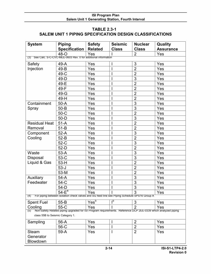
ISI Program Plan Salem Unit 1 Generating Station, Fourth Interval
2-14 ISI-S1-LTP4-2.0 Revision 0
TABLE 2.3-1 SALEM UNIT 1 PIPING SPECIFICATION DESIGN CLASSIFICATIONS
System Piping
Specification Safety Related
Seismic Class
Nuclear Class
Quality Assurance
48-O Yes I 2 Yes (3) See Calc. S-C-CVC-MEE-0603 Rev. 0 for additional information Safety Injection
49-A Yes I 3 Yes 49-B Yes I 2 Yes 49-C Yes I 2 Yes 49-D Yes I 3 Yes 49-E Yes I 2 Yes 49-F Yes I 2 Yes 49-G Yes I 2 Yes 49-H Yes I 2 Yes
Containment Spray
50-A Yes I 3 Yes 50-B Yes I 3 Yes 50-C Yes I 2 Yes 50-D Yes I 3 Yes
Residual Heat Removal
51-A Yes I 2 Yes 51-B Yes I 2 Yes
Component Cooling
52-A Yes I 3 Yes 52-B Yes I 2 Yes 52-C Yes I 3 Yes 52-D Yes I 2 Yes
Waste Disposal Liquid & Gas
53-A Yes I 3 Yes 53-C Yes I 3 Yes 53-H Yes I 2 Yes 53-J Yes I 2 Yes 53-M Yes I 2 Yes
Auxiliary Feedwater
54-A Yes I 3 Yes 54-C Yes I 3 Yes 54-D Yes I 3 Yes 54-E4 Yes I 3 Yes
(4) For piping between isolation check valves and SG feed line see Piping Schedule SPS16 Group A Spent Fuel Cooling
55-B Yes5 I5 3 Yes 55-C Yes I 2 Yes
(5) Non-Safety Related piping upgraded for ISI Program requirements. Reference DCP 2EE-0339 which analyzed piping
class 55B to Seismic Category 1. Sampling 56-A Yes I 2 Yes
56-C Yes I 2 Yes Steam Generator Blowdown
59-A Yes I 2 Yes

ISI Program Plan Salem Unit 1 Generating Station, Fourth Interval
2-15 ISI-S1-LTP4-2.0 Revision 0
TABLE 2.3-2
SALEM UNIT 1 INSERVICE INSPECTION BOUNDARY DRAWINGS
DOC ID. SHEET NO. TITLE S1-ISI-201 1 UNIT 1 - REACTOR COOLANT S1-ISI-201 2 UNIT 1 - REACTOR COOLANT S1-ISI-201 3 UNIT 1 - REACTOR COOLANT
S1-ISI-202 3 UNIT 1 - STEAM GENERATOR FEED & CONDENSATE
S1-ISI-203 1 UNIT 1 - MAIN, REHEAT & TURBINE BY-PASS STEAM
S1-ISI-203 2 UNIT 1 - MAIN, REHEAT & TURBINE BY-PASS STEAM
S1-ISI-203 6 UNIT 1 - MAIN, REHEAT & TURBINE BY-PASS STEAM
S1-ISI-216 1 UNIT 1 - CHILLED WATER S1-ISI-216 3 UNIT 1 - CHILLED WATER S1-ISI-217 2 UNIT 1 - COMPRESSED AIR S1-ISI-217 3 UNIT 1 - COMPRESSED AIR S1-ISI-222 1 UNIT 1 - FIRE PROTECTION
S1-ISI-225 1 UNIT 1 - STEAM GENERATOR DRAINS & BLOWDOWN
S1-ISI-225 2 UNIT 1 - STEAM GENERATOR DRAINS & BLOWDOWN
S1-ISI-228 1 UNIT 1 - CHEMICAL & VOLUME CONTROL OPERATION
S1-ISI-228 2 UNIT 1 - CHEMICAL & VOLUME CONTROL OPERATION
S1-ISI-228 3 UNIT 1 - CHEMICAL & VOLUME CONTROL OPERATION
S1-ISI-229 1 UNIT 1 - CHEMICAL & VOLUME CONTROL OPERATION
S1-ISI-229 2 UNIT 1 - CHEMICAL & VOLUME CONTROL OPERATION
S1-ISI-231 1 UNIT 1 - COMPONENT COOLING S1-ISI-231 2 UNIT 1 - COMPONENT COOLING S1-ISI-231 3 UNIT 1 - COMPONENT COOLING S1-ISI-232 1 UNIT 1 - RESIDUAL HEAT REMOVAL S1-ISI-232 2 UNIT 1 - RESIDUAL HEAT REMOVAL S1-ISI-233 1 UNIT 1 - SPENT FUEL COOLING S1-ISI-234 1 UNIT 1 - SAFETY INJECTION S1-ISI-234 2 UNIT 1 - RESIDUAL HEAT REMOVAL

ISI Program Plan Salem Unit 1 Generating Station, Fourth Interval
2-16 ISI-S1-LTP4-2.0 Revision 0
TABLE 2.3-2 SALEM UNIT 1 INSERVICE INSPECTION BOUNDARY DRAWINGS
DOC ID. SHEET NO. TITLE S1-ISI-234 3 UNIT 1 - RESIDUAL HEAT REMOVAL S1-ISI-234 4 UNIT 1 - RESIDUAL HEAT REMOVAL S1-ISI-235 1 UNIT 1 - CONTAINMENT SPRAY S1-ISI-236 1 UNIT 1 - AUXILIARY FEEDWATER S1-ISI-238 1 UNIT 1 - REACTOR CONTAINMENT – VENTILATION S1-ISI-238 2 UNIT 1 - REACTOR CONTAINMENT – VENTILATION S1-ISI-239 1 UNIT 1 - WASTE DISPOSAL – LIQUID S1-ISI-239 2 UNIT 1 - WASTE DISPOSAL – LIQUID S1-ISI-239 3 UNIT 1 - WASTE DISPOSAL – LIQUID S1-ISI-240 2 UNIT 1 - WASTE DISPOSAL – GAS S1-ISI-240 3 UNIT 1 - WASTE DISPOSAL – GAS S1-ISI-242 1 UNIT 1 - SERVICE WATER NUCLEAR AREA S1-ISI-242 2 UNIT 1 - SERVICE WATER NUCLEAR AREA S1-ISI-242 3 UNIT 1 - SERVICE WATER NUCLEAR AREA S1-ISI-242 4 UNIT 1 - SERVICE WATER NUCLEAR AREA S1-ISI-242 5 UNIT 1 - SERVICE WATER NUCLEAR AREA S1-ISI-242 6 UNIT 1 - SERVICE WATER NUCLEAR AREA S1-ISI-242 7 UNIT 1 - SERVICE WATER NUCLEAR AREA S1-ISI-244 1 UNIT 1 – SAMPLING S1-ISI-244 3 UNIT 1 – SAMPLING
S1-ISI-246 1 UNIT 1 - DEMINERALIZED WATER - RESTRICTED AREAS
S1-ISI-247 1 UNIT 1 - REACT. CONT. & PENETRATION AREA, CONTROL AIR
S1-ISI-247 3 UNIT 1 - REACT. CONT. & PENETRATION AREA, CONTROL AIR

ISI Program Plan Salem Unit 1 Generating Station, Fourth Interval
2-17 ISI-S1-LTP4-2.0 Revision 0
2.4 ISI Isometric and Component Drawings for Nonexempt ISI Class Components and Supports
ISI Isometric and Component Drawings were developed to detail the ISI Class 1and 2 components (welds, bolting, etc.) and support locations at Salem Unit 1. These ISI component and support locations are identified on the ISI Isometric and Component Drawings listed in Table 2.4-1. For Class 3 components plant drawings (e.g., construction isometrics) are used to locate and identify applicable components and their supports. These are also listed in Table 2.4-1.
Salem Unit 1‘s ISI Program, including the ISI Database, ISI Classification Basis Document, and ISI Selection Document, addresses the nonexempt components, which require examination and testing.

ISI Program Plan Salem Unit 1 Generating Station, Fourth Interval
2-18 ISI-S1-LTP4-2.0 Revision 0
TABLE 2.4-1
ISI ISOMETRIC AND COMPONENT DRAWINGS
ISI Sketch Number System
Class 1 & 2 ISI Line
No./Class 3 PSEG Line
No.
Construction Isometric
No./Sheet No. P&ID Boundary Diagram No.
Class 1 Systems
A-1 Reactor Pressure Vessel N/A N/A N/A N/A
A-2
Reactor Pressure Vessel
Closure Head Layout
N/A N/A N/A N/A
A-2B Control Rod Drive Housings N/A N/A N/A N/A
A-3 Pressurizer N/A N/A N/A N/A
A-4 Steam
Generator No. 11
N/A N/A N/A N/A
A-5 Steam
Generator No. 12
N/A N/A N/A N/A
A-6 Steam
Generator No. 13
N/A N/A N/A N/A
A-7 Steam
Generator No. 14
N/A N/A N/A N/A
A-8 Chemical and Volume Control
12-CV-1143 3-CV-1143 CVC-1-4B/1 205201-03 ISI201-03
A-8B Penetration N/A 207497 N/A N/A
A-9 Chemical and Volume Control 3-CV-1141 CVC-1-4B/1 205201-03 ISI 201-03
A-10 Chemical and Volume Control 3-CV-1133 CVC-1-4B/1 205201-02
205228-02 ISI 201-02 ISI 228-02
A-11 Chemical and Volume Control 2-CV-1175 RC-1-2B/1 205201-01
205228-02 ISI 201-01 ISI 228-02
A-12 Chemical and Volume Control
2-CV-1175 (Cont‘d) RC-1-2B/1 205201-01
205228-02 ISI 201-01 ISI 228-02
A-13 Pressurizer Relief 6-PR-1105 RC-1-2A/1 205201-01 ISI 201-01
A-14 Pressurizer Relief 6-PR-1104 RC-1-2A/1 205201-01 ISI 201-01
A-15 Pressurizer Relief 6-PR-1103 RC-1-2A/1 205201-01 ISI 201-01
A-16 Pressurizer Relief
4-PR-1100 3-PR-1107 RC-1-2A/1 205201-01 ISI 201-01

ISI Program Plan Salem Unit 1 Generating Station, Fourth Interval
2-19 ISI-S1-LTP4-2.0 Revision 0
TABLE 2.4-1 ISI ISOMETRIC AND COMPONENT DRAWINGS
ISI Sketch Number System
Class 1 & 2 ISI Line
No./Class 3 PSEG Line
No.
Construction Isometric
No./Sheet No. P&ID Boundary Diagram No.
A-17 Pressurizer Relief 3-PR-1106 RC-1-2A/1 205201-01 ISI 201-01
A-18 Pressurizer Surge 14-PS-1131 RC-1-1A/1 205232-01
205232-02 ISI 232-01 ISI 232-02
A-19 Pressurizer Spray 4-PS-1131 RC-1-2B/1 205232-01
205232-02 ISI 232-01 ISI 232-02
A-20 Pressurizer Spray
4-PS-1131 (cont‘d) RC-1-2B/1 205232-01
205232-02 ISI 232-01 ISI 232-02
A-21 Pressurizer Spray
4-PS-1131 (cont‘d) RC-1-2B/1 205232-01
205232-02 ISI 232-01 ISI 232-02
A-22 Pressurizer Spray 4-PS-1111 RC-1-2B/1 205201-01
205201-02 ISI 201-01 ISI 201-02
A-23 Reactor Coolant 31-RC-1140 3-RC-1143 RC-1-1B/1 205201-03 ISI 201-03
A-24 Reactor Coolant 31-RC-1130 3-RC-1133 RC-1-1A/1 205201-02 ISI 201-02
A-25 Reactor Coolant 31-RC-1120 3-RC-1123 RC-1-1B/1 205201-03 ISI 201-03
A-26 Reactor Coolant 31-RC-1110 3-RC-1113 RC-1-1A/1 205201-02 ISI 201-02
A-27 Reactor Coolant 29-RC-1140 RC-1-1B/1 205201-03 ISI 201-03 A-28 Reactor Coolant 29-RC-1130 RC-1-1A/1 205201-02 ISI 201-02 A-29 Reactor Coolant 29-RC-1120 RC-1-1B/1 205201-03 ISI 201-03 A-30 Reactor Coolant 29-RC-1110 RC-1-1A/1 205201-02 ISI 201-02
A-31 Reactor Coolant
27-1/2-RC-1140
2-RC-1142 RC-1-1B/1 205201-03 ISI 201-03
A-32 Reactor Coolant 27-1/2-RC-
1130 2-RC-1132
RC-1-1A/1 205201-02 ISI 201-02
A-33 Reactor Coolant 27-1/2-RC-
1120 2-RC-1122
RC-1-1B/1 205201-03 ISI 201-03
A-34 Reactor Coolant 27-1/2-RC-
1110 2-RC-1112
RC-1-1A/1 205201-02 ISI 201-02
A-47 Reactor Coolant
2-RC-1111 2-RC-1121 2-RC-1131 2-RC-1141
RC-1-2C/1 205201-02 ISI 201-02
A-52 Residual Heat Removal 14-RH-1111 RH-1-3A/2 205201-02
205232-02 ISI 201-02 ISI 232-02
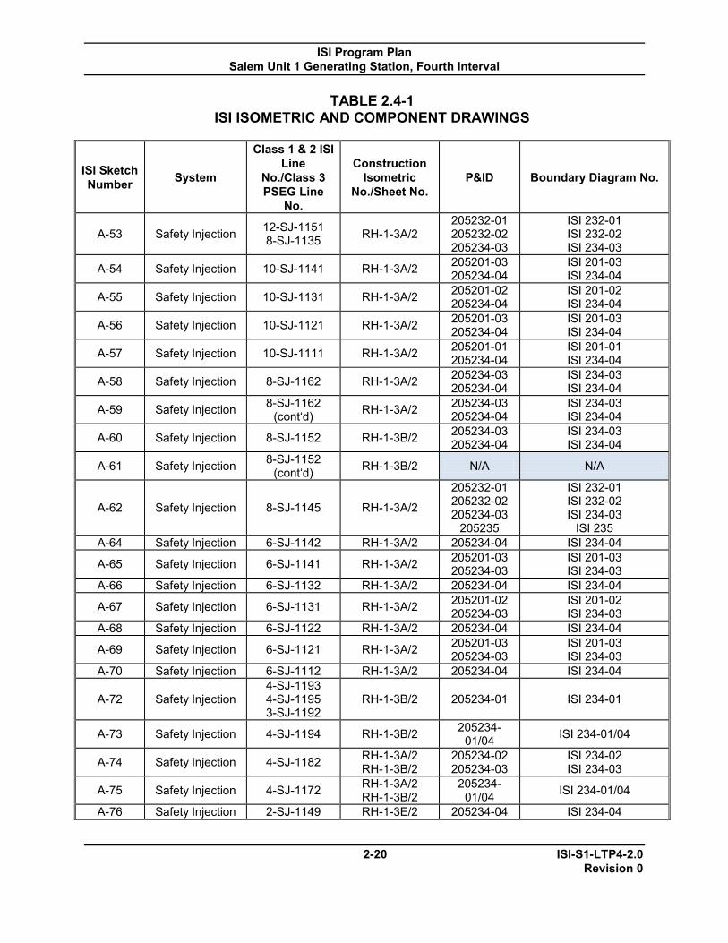
ISI Program Plan Salem Unit 1 Generating Station, Fourth Interval
2-20 ISI-S1-LTP4-2.0 Revision 0
TABLE 2.4-1 ISI ISOMETRIC AND COMPONENT DRAWINGS
ISI Sketch Number System
Class 1 & 2 ISI Line
No./Class 3 PSEG Line
No.
Construction Isometric
No./Sheet No. P&ID Boundary Diagram No.
A-53 Safety Injection 12-SJ-1151 8-SJ-1135 RH-1-3A/2
205232-01 205232-02 205234-03
ISI 232-01 ISI 232-02 ISI 234-03
A-54 Safety Injection 10-SJ-1141 RH-1-3A/2 205201-03 205234-04
ISI 201-03 ISI 234-04
A-55 Safety Injection 10-SJ-1131 RH-1-3A/2 205201-02 205234-04
ISI 201-02 ISI 234-04
A-56 Safety Injection 10-SJ-1121 RH-1-3A/2 205201-03 205234-04
ISI 201-03 ISI 234-04
A-57 Safety Injection 10-SJ-1111 RH-1-3A/2 205201-01 205234-04
ISI 201-01 ISI 234-04
A-58 Safety Injection 8-SJ-1162 RH-1-3A/2 205234-03 205234-04
ISI 234-03 ISI 234-04
A-59 Safety Injection 8-SJ-1162 (cont‘d) RH-1-3A/2 205234-03
205234-04 ISI 234-03 ISI 234-04
A-60 Safety Injection 8-SJ-1152 RH-1-3B/2 205234-03 205234-04
ISI 234-03 ISI 234-04
A-61 Safety Injection 8-SJ-1152 (cont‘d) RH-1-3B/2 N/A N/A
A-62 Safety Injection 8-SJ-1145 RH-1-3A/2
205232-01 205232-02 205234-03
205235
ISI 232-01 ISI 232-02 ISI 234-03
ISI 235 A-64 Safety Injection 6-SJ-1142 RH-1-3A/2 205234-04 ISI 234-04
A-65 Safety Injection 6-SJ-1141 RH-1-3A/2 205201-03 205234-03
ISI 201-03 ISI 234-03
A-66 Safety Injection 6-SJ-1132 RH-1-3A/2 205234-04 ISI 234-04
A-67 Safety Injection 6-SJ-1131 RH-1-3A/2 205201-02 205234-03
ISI 201-02 ISI 234-03
A-68 Safety Injection 6-SJ-1122 RH-1-3A/2 205234-04 ISI 234-04
A-69 Safety Injection 6-SJ-1121 RH-1-3A/2 205201-03 205234-03
ISI 201-03 ISI 234-03
A-70 Safety Injection 6-SJ-1112 RH-1-3A/2 205234-04 ISI 234-04
A-72 Safety Injection 4-SJ-1193 4-SJ-1195 3-SJ-1192
RH-1-3B/2 205234-01 ISI 234-01
A-73 Safety Injection 4-SJ-1194 RH-1-3B/2 205234-01/04 ISI 234-01/04
A-74 Safety Injection 4-SJ-1182 RH-1-3A/2 RH-1-3B/2
205234-02 205234-03
ISI 234-02 ISI 234-03
A-75 Safety Injection 4-SJ-1172 RH-1-3A/2 RH-1-3B/2
205234-01/04 ISI 234-01/04
A-76 Safety Injection 2-SJ-1149 RH-1-3E/2 205234-04 ISI 234-04
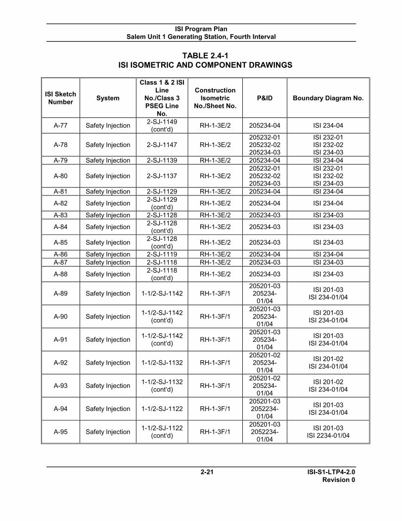
ISI Program Plan Salem Unit 1 Generating Station, Fourth Interval
2-21 ISI-S1-LTP4-2.0 Revision 0
TABLE 2.4-1 ISI ISOMETRIC AND COMPONENT DRAWINGS
ISI Sketch Number System
Class 1 & 2 ISI Line
No./Class 3 PSEG Line
No.
Construction Isometric
No./Sheet No. P&ID Boundary Diagram No.
A-77 Safety Injection 2-SJ-1149 (cont‘d) RH-1-3E/2 205234-04 ISI 234-04
A-78 Safety Injection 2-SJ-1147 RH-1-3E/2 205232-01 205232-02 205234-03
ISI 232-01 ISI 232-02 ISI 234-03
A-79 Safety Injection 2-SJ-1139 RH-1-3E/2 205234-04 ISI 234-04
A-80 Safety Injection 2-SJ-1137 RH-1-3E/2 205232-01 205232-02 205234-03
ISI 232-01 ISI 232-02 ISI 234-03
A-81 Safety Injection 2-SJ-1129 RH-1-3E/2 205234-04 ISI 234-04
A-82 Safety Injection 2-SJ-1129 (cont‘d) RH-1-3E/2 205234-04 ISI 234-04
A-83 Safety Injection 2-SJ-1128 RH-1-3E/2 205234-03 ISI 234-03
A-84 Safety Injection 2-SJ-1128 (cont‘d) RH-1-3E/2 205234-03 ISI 234-03
A-85 Safety Injection 2-SJ-1128 (cont‘d) RH-1-3E/2 205234-03 ISI 234-03
A-86 Safety Injection 2-SJ-1119 RH-1-3E/2 205234-04 ISI 234-04 A-87 Safety Injection 2-SJ-1118 RH-1-3E/2 205234-03 ISI 234-03
A-88 Safety Injection 2-SJ-1118 (cont‘d) RH-1-3E/2 205234-03 ISI 234-03
A-89 Safety Injection 1-1/2-SJ-1142 RH-1-3F/1 205201-03 205234-
01/04
ISI 201-03 ISI 234-01/04
A-90 Safety Injection 1-1/2-SJ-1142 (cont‘d) RH-1-3F/1
205201-03 205234-
01/04
ISI 201-03 ISI 234-01/04
A-91 Safety Injection 1-1/2-SJ-1142 (cont‘d) RH-1-3F/1
205201-03 205234-
01/04
ISI 201-03 ISI 234-01/04
A-92 Safety Injection 1-1/2-SJ-1132 RH-1-3F/1 205201-02 205234-
01/04
ISI 201-02 ISI 234-01/04
A-93 Safety Injection 1-1/2-SJ-1132 (cont‘d) RH-1-3F/1
205201-02 205234-
01/04
ISI 201-02 ISI 234-01/04
A-94 Safety Injection 1-1/2-SJ-1122 RH-1-3F/1 205201-03 2052234-
01/04
ISI 201-03 ISI 234-01/04
A-95 Safety Injection 1-1/2-SJ-1122 (cont‘d) RH-1-3F/1
205201-03 2052234-
01/04
ISI 201-03 ISI 2234-01/04

ISI Program Plan Salem Unit 1 Generating Station, Fourth Interval
2-22 ISI-S1-LTP4-2.0 Revision 0
TABLE 2.4-1 ISI ISOMETRIC AND COMPONENT DRAWINGS
ISI Sketch Number System
Class 1 & 2 ISI Line
No./Class 3 PSEG Line
No.
Construction Isometric
No./Sheet No. P&ID Boundary Diagram No.
A-96 Safety Injection 1-1/2-SJ-1112 RH-1-3F/1 205201-02 205234-
01/04
ISI 201-02 ISI 234-01/04
A-97 Safety Injection 1-1/2-SJ-1112 (cont‘d) RH-1-3F/1
205201-02 205234-
01/04
ISI 201-02 ISI 234-01/04
A-98 Reactor Coolant Pumps N/A N/A N/A N/A
Class 2 Systems
B-1 Charging Pump No. 13 N/A N/A N/A N/A
B-2 Chemical and
Volume Control tank
N/A N/A N/A N/A
B-3 Excess Letdown Heat Exchanger N/A N/A N/A N/A
B-4 Deleted N/A N/A N/A N/A
B-5 Letdown (Non-Regenerative)
Heat Exchanger N/A N/A N/A N/A
B-7 Regenerative Heat Exchanger N/A N/A N/A N/A
B-8 RHR Heat Exchanger
No.11 N/A N/A N/A N/A
B-9 RHR Heat
Exchanger No. 12
N/A N/A N/A N/A
B-10 Steam Generator Feed
14-BF-2141 16-BF-2141 SGF-1-1B/4 205202-03 ISI 202-03
B-10-1 Steam Generator Feed
14-BF-2141 16-BF-2141 SGF-1-1B/4 205202-03 ISI 202-03
B-10C Penetrations N/A N/A 207497 N/A
B-11 Steam Generator Feed
14-BF-2131 16-BF-2131 SGF-1-1B/3 205202-03 ISI 202-03
B-11A-1 Steam Generator Feed
14-BF-2131 16-BF-2131 SGF-1-1B/3 205202-03 ISI 202-03

ISI Program Plan Salem Unit 1 Generating Station, Fourth Interval
2-23 ISI-S1-LTP4-2.0 Revision 0
TABLE 2.4-1 ISI ISOMETRIC AND COMPONENT DRAWINGS
ISI Sketch Number System
Class 1 & 2 ISI Line
No./Class 3 PSEG Line
No.
Construction Isometric
No./Sheet No. P&ID Boundary Diagram No.
B-12 Steam Generator Feed
14-BF-2121 16-BF-2121 SGF-1-1B/2 205202-03 ISI 202-03
B-12A-1 Steam Generator Feed
14-BF-2121 16-BF-2121 SGF-1-1B/2 205202-03 ISI 202-03
B-13 Steam Generator Feed
14-BF-2111 16-BF-2111 SGF-1-1B/1 205202-03 ISI 202-03
B-13A-1 Steam Generator Feed
14-BF-2111 16-BF-2111 SGF-1-1B/1 205202-03 ISI 202-03
B-14 Containment Spray
8-CS-2115 8-CS-2125
RH-1-2B/2 RH-1-3B/2
205234-03 205235
ISI 234-03 ISI 235
B-15 Chemical and Volume Control 8-CV-2101 RH-1-2A/1 205228-02
205234-01 ISI 228-02 ISI 234-01
B-16 Chemical and Volume Control
8-CV-2101 (cont‘d) CVC-1-2C/2 205228-02
205234-01 ISI 228-02 ISI 234-01
B-17 Chemical and Volume Control
8-CV-2101 (cont‘d)
CVC-1-2A/4 CVC-1-2B/2
205228-02 205234-01
ISI 228-02 ISI 234-01
B-18 Chemical and Volume Control 6-CV-2112 CVC-1-2C/2 205228-02 ISI 228-02
B-19 Chemical and Volume Control 6-CV-2111 CVC-1-2B/2 205228-02 ISI 228-02
B-20 Chemical and Volume Control 6-CV-2101 CVC-1-2B/2 205234-01 ISI 234-01
B-21 Main Steam 34-MS-2141 MS-1-2/4 205203-01/06 ISI 203-01/06
B-22 Main Steam 34-MS-2131 MS-1-2/4 205203-01/06 ISI 203-01/06
B-23 Main Steam 34-MS-2121 34-MS-2121 MS-1-2/4 205203-
01/06 ISI 203-01/06
B-24 Main Steam 34-MS-2111 MS-1-2/4 205203-01/06 ISI 203-01/06
B-25 Main Steam 30-MS02141 32-MS-2141 MS-1-2/3 205203-
01/06 ISI 203-01/06
B-26 Main Steam 30-MS02131 32-MS-2131 MS-1-2/3 205203-
01/06 ISI 203-01/06
B-27 Main Steam 30-MS02121 32-MS-2121 MS-1-2/3 205203-
01/06 ISI 203-01/06
B-28 Main Steam 30-MS02111 32-MS-2111 MS-1-2/3 205203-
01/06 ISI 203-01/06
B-29 Main Steam
8-MS-2141 8-MS-2142 8-MS-2143 8-MS-2144 8-MS-2145 6-MS-2146
MS-1-2/4 205203-01/06 ISI 203-01/06

ISI Program Plan Salem Unit 1 Generating Station, Fourth Interval
2-24 ISI-S1-LTP4-2.0 Revision 0
TABLE 2.4-1 ISI ISOMETRIC AND COMPONENT DRAWINGS
ISI Sketch Number System
Class 1 & 2 ISI Line
No./Class 3 PSEG Line
No.
Construction Isometric
No./Sheet No. P&ID Boundary Diagram No.
B-30 Main Steam
8-MS-2131 8-MS-2132 8-MS-2133 8-MS-2134 8-MS-2135 6-MS-2136
MS-1-2/4 205203-01/06 ISI 203-01/06
B-31 Main Steam
8-MS-2121 8-MS-2122 8-MS-2123 8-MS-2124 8-MS-2125 6-MS-2126
MS-1-2/4 205203-01/06 ISI 203-01/06
B-32 Main Steam
8-MS-2111 8-MS-2112 8-MS-2113 8-MS-2114 8-MS-2115 6-MS-2116
MS-1-2/4 205203-01/06 ISI 203-01/06
B-33 Main Steam
6-MS-2147 6-MS-2137 6-MS-2127 6-MS-2117
MS-1-2/4 205203-01/06 ISI 203-01/06
B-34 Main Steam 6-MS-2131 MS-1-4/1 205203-01/06 ISI 203-01/06
B-35 Main Steam 6-MS-2131 (cont‘d) MS-1-4/1 205203-
01/06 ISI 203-01/06
B-36 Main Steam 6-MS-2111 MS-1-4/1 205203-01/06 ISI 203-01/06
B-37 Pressurizer Relief 12-PR-2101 RC-1-2A/1 205201-01 ISI 201-01
B-38 Pressurizer Relief
12-PR-2101 (cont‘d) RC-1-2A/1 205201-01 ISI 201-01
B-39 Pressurizer Relief 6-PR-2105 RC-1-2A/1 205201-01 ISI 201-01
B-40 Pressurizer Relief 6-PR-2104 RC-1-2A/1 205201-01 ISI 201-01
B-41 Pressurizer Relief 6-PR-2103 RC-1-2A/1 205201-01 ISI 201-01
B-42 Pressurizer Relief 6-PR-2102 RC-1-2A/1 205201-01 ISI 201-01
B-43 Pressurizer Relief 6-PR-2101 RC-1-2A/1 205201-01 ISI 201-01
B-44 Residual Heat Removal 14-RH-2124 RC-1-1B/1 205232-02
205234-03 ISI 232-02 ISI 234-03

ISI Program Plan Salem Unit 1 Generating Station, Fourth Interval
2-25 ISI-S1-LTP4-2.0 Revision 0
TABLE 2.4-1 ISI ISOMETRIC AND COMPONENT DRAWINGS
ISI Sketch Number System
Class 1 & 2 ISI Line
No./Class 3 PSEG Line
No.
Construction Isometric
No./Sheet No. P&ID Boundary Diagram No.
B-45 Residual Heat Removal 14-RH-2114 RC-1-1A/1
RC-1-1B/1 205232-01 205234-03
ISI 232-01 ISI 234-03
B-46 Residual Heat Removal 14-RH-2112
RH-1-3A/2 RH-1-3B/2 RH-1-1B/2
205232-02 ISI 232-02
B-47 Residual Heat Removal 8-RH-2174 RH-1-1A/2 205232-01 ISI 232-01
B-48 Residual Heat Removal 8-RH-2173 RH-1-1A/2
RH-1-1B/2 205232-01 205232-02
ISI 232-01 ISI 232-02
B-49 Residual Heat Removal 8-RH-2153 RH-1-1B/2 205232-01 ISI 232-01
B-50 Residual Heat Removal 8-RH-2126 RH-1-1B/2
205232-01 205232-02 205234-
01/04
ISI 232-01 ISI 232-02
ISI 234-01/04
B-51 Residual Heat Removal 8-RH-2116 RH-1-1A/2 205232-01 ISI 232-01
B-52 Safety Injection 14-SJ-2124 14-SJ-2114
RH-1-1A/2 RH-1-1B/2
205232-02 205234-03
ISI 232-02 ISI 234-03
B-53 Safety Injection 12-SJ-2169 RH-1-1B/2 205232-02 205234-03
ISI 232-02 ISI 234-03
B-54 Safety Injection 12-SJ-2152 RH-1-3A/2 RH-1-3B/2 RH-1-1A/2
205232-01 ISI 232-01
B-55 Safety Injection 8-SJ-2162 RH-1-1B/2 RH-1-2B/2 RH-1-3B/2
205232-01 205232-02
ISI 232-01 ISI 232-02
B-56 Safety Injection 8-SJ-2152 RH-1-1A/2 RH-1-2B/2 RH-1-1B/2
205232-01 205234-03
ISI 232-01 ISI 234-03
B-57 Safety Injection 8-SJ-2125 RH-1-1B/2 RH-1-2B/2
205232-01 205232-02 205234-01 205234-03
ISI 232-01 ISI 232-02 ISI 234-01 ISI 234-03
B-58 Safety Injection 8-SJ-2115 RH-1-1A/2 RH-1-2B/2
205232-01 205232-02 205234-
01/04
ISI 232-01 ISI 232-02
ISI 234-01/04
B-59 Safety Injection 6-SJ-2103 6-SJ-2104 RH-1-3B/2 205234-01 ISI 234-01
B-61 Containment Spray
8-CS-2132 8-CS-2131 CS-1-2C/1 205235 ISI 235
B-62 Containment Spray 8-CS-2130 RH-1-3B/2
CS-1-2C/1 205235 ISI 235

ISI Program Plan Salem Unit 1 Generating Station, Fourth Interval
2-26 ISI-S1-LTP4-2.0 Revision 0
TABLE 2.4-1 ISI ISOMETRIC AND COMPONENT DRAWINGS
ISI Sketch Number System
Class 1 & 2 ISI Line
No./Class 3 PSEG Line
No.
Construction Isometric
No./Sheet No. P&ID Boundary Diagram No.
B-63 Containment Spray 8-CS-2123 CS-1-1A/1
CS-1-2C/1 205235 ISI 235
B-64 Containment Spray
8-CS-2123 (cont‘d)
CS-1-1A/1 CS-1-2C/1 205235 ISI 235
B-65 Containment Spray 8-CS-2122 CS-1-2C/1
RH-1-3B/2 205235 ISI 235
B-66 Containment Spray 8-CS-2114 CS-1-1A/1
CS-1-2C/1 205235 ISI 235
B-67 Containment Spray
8-CS-2114 (cont‘d)
CS-1-1A/1 CS-1-2C/1 205235 ISI 235
B-68 Chemical and Volume Control 3-CV-2169 CVC-1-2B/2 205228-02 ISI 228-02
B-69 Chemical and Volume Control 3-CV-2168 CVC-1-2C/2 205228-02 ISI 228-02
B-70 Chemical and Volume Control 3-CV-2163
CVC-1-2B/2 CVC-1-4F/2 CVC-1-2A/2
205228-02 ISI 228-02
B-71 Chemical and Volume Control
3-CV-2160 3-CV-2185
CVC-1-2B/2 CVC-1-2C/2 205228-02 ISI 228-02
B-72 Chemical and Volume Control
3-CV-2160 3-CV-2185
(cont‘d)
CVC-1-2B/2 CVC-1-2C/2 205228-02 ISI 228-02
B-73 Chemical and Volume Control 3-CV-2156 CVC-1-4B/1 205228-02 ISI 228-02
B-74 Chemical and Volume Control 3-CV-2151
CVC-1-2A/2 CVC-1-2B/2 CVC-1-4B/1
205228-02 ISI 228-02
B-78 Chemical and Volume Control 2-CV-2194 CVC-1-4F/2 205228-02
205228-03 ISI 228-02 ISI 228-03
B-79 Chemical and Volume Control 2-CV-2187 CVC-1-2B/2 205228-02 ISI 228-02
B-80 Chemical and Volume Control 2-CV-2186 CVC-1-2B/2 205228-02 ISI 228-02
B-81 Chemical and Volume Control 2-CV-2170 CVC-1-4F/2 205228-02
205228-03 ISI 28-02 ISI 228-03
B-83 Chemical and Volume Control 2-CV-2162 CVC-1-2B/2 205228-02 ISI 228-02
B-84 Chemical and Volume Control 2-CV-2161 CVC-1-2B/2 205228-02 ISI 228-02
B-87 Chemical and Volume Control 2-CV-2138 CVC-1-4F/2 205228-02
205228-03 ISI 228-02 ISI 228-03
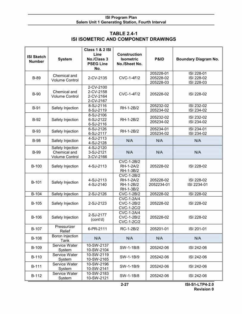
ISI Program Plan Salem Unit 1 Generating Station, Fourth Interval
2-27 ISI-S1-LTP4-2.0 Revision 0
TABLE 2.4-1 ISI ISOMETRIC AND COMPONENT DRAWINGS
ISI Sketch Number System
Class 1 & 2 ISI Line
No./Class 3 PSEG Line
No.
Construction Isometric
No./Sheet No. P&ID Boundary Diagram No.
B-89 Chemical and Volume Control 2-CV-2135 CVC-1-4F/2
205228-01 205228-02 205228-03
ISI 228-01 ISI 228-02 ISI 228-03
B-90 Chemical and Volume Control
2-CV-2100 2-CV-2158 2-CV-2164 2-CV-2167
CVC-1-4F/2 205228-02 ISI 228-02
B-91 Safety Injection 8-SJ-2116 8-SJ-2119 RH-1-2B/2 205232-02
205234-02 ISI 232-02 ISI 234-02
B-92 Safety Injection 8-SJ-2106 6-SJ-2122 6-SJ-2116
RH-1-2B/2 205232-02 205234-02
ISI 232-02 ISI 234-02
B-93 Safety Injection 6-SJ-2126 6-SJ-2117 RH-1-2B/2 205234-01
205234-02 ISI 234-01 ISI 234-02
B-98 Safety Injection 4-SJ-2113 4-SJ-2128 N/A N/A N/A
B-99 Safety Injection Chemical and
Volume Control
4-SJ-2120 3-SJ-2121 3-CV-2166
N/A N/A N/A
B-100 Safety Injection 4-SJ-2113 CVC-1-2B/2 RH-1-2A/2 RH-1-3B/2
205228-02 ISI 228-02
B-101 Safety Injection 4-SJ-2113 4-SJ-2140
CVC-1-2B/2 RH-1-2A/2 RH-1-2B/2 RH-1-3B/2
205228-02 2052234-01
ISI 228-02 ISI 2234-01
B-104 Safety Injection 2-SJ-2126 CVC-1-2B/2 205228-02 ISI 228-02
B-105 Safety Injection 2-SJ-2123 CVC-1-2A/4 CVC-1-2B/2 CVC-1-2C/2
205228-02 ISI 228-02
B-106 Safety Injection 2-SJ-2177 (cont‘d)
CVC-1-2A/4 CVC-1-2B/2 CVC-1-2C/2
205228-02 ISI 228-02
B-107 Pressurizer Relief 6-PR-2111 RC-1-2B/2 205201-01 ISI 201-01
B-108 Boron Injection Tank N/A N/A N/A N/A
B-109 Service Water System
10-SW-2137 10-SW-2104 SW-1-1B/8 205242-06 ISI 242-06
B-110 Service Water System
10-SW-2119 10-SW-2165 SW-1-1B/9 205242-06 ISI 242-06
B-111 Service Water System
10-SW-2196 10-SW-2141 SW-1-1B/9 205242-06 ISI 242-06
B-112 Service Water System
10-SW-2183 10-SW-2121 SW-1-1B/8 205242-06 ISI 242-06

ISI Program Plan Salem Unit 1 Generating Station, Fourth Interval
2-28 ISI-S1-LTP4-2.0 Revision 0
TABLE 2.4-1 ISI ISOMETRIC AND COMPONENT DRAWINGS
ISI Sketch Number System
Class 1 & 2 ISI Line
No./Class 3 PSEG Line
No.
Construction Isometric
No./Sheet No. P&ID Boundary Diagram No.
B-113 Service Water System
10-SW-2103 10-SW-2198 SW-1-1B/10 205242-06 ISI 242-06
B-114 Auxiliary
Feedwater System
4-AF-2111 AF-1-3A/2 205202-03 205236-01
ISI 202-03 ISI 236-01
B-115 Auxiliary
Feedwater System
4-AF-2112 AF-1-3A/2 205202-03 205236-01
ISI 202-03 ISI 236-01
B-116 Auxiliary
Feedwater System
4-AF-2113 AF-1-3A/2 205202-03 205236-01
ISI 202-03 ISI 236-01
B-117 Auxiliary
Feedwater System
4-AF-2114 AF-1-3A/2 205202-03 205236-01
ISI 202-03 ISI 236-01
Class 3 Systems N/A Auxiliary
Feedwater 10-1AF-1000 AF-1-2A/1 205236 603236
N/A Auxiliary Feedwater 8-1AF-1004 AF-1-2A/1 205236 603236
N/A Auxiliary Feedwater 6-1AF-1009 AF-1-2A/1 205236 603236
N/A Auxiliary Feedwater 6-1AF-1012 AF-1-2A/1 205236 603236
N/A Auxiliary Feedwater 4-1AF-1030 AF-1-2B/1 205236 603236
N/A Auxiliary Feedwater 2-1AF-1035 AF-1-2A/1 205236 603236
N/A Auxiliary Feedwater 4-1AF-1037 AF-1-2B/1 205236 603236
N/A Auxiliary Feedwater 4-1AF-1039 AF-1-2B/1 205236 603236
N/A Auxiliary Feedwater 4-1AF-1044 AF-1-2B/1 205236 603236
N/A Auxiliary Feedwater 6-1AF-1046 AF-1-2B/1 205236 603236
N/A Auxiliary Feedwater 4-1AF-1048 AF-1-2B/1 205236 603236
N/A Auxiliary Feedwater 4-1AF-1049 AF-1-2B/1 205236 603236
N/A Auxiliary Feedwater 4-1AF-1050 AF-1-2B/1 205236 603236
N/A Auxiliary Feedwater 4-1AF-1051 AF-1-2B/1 205236 603236

ISI Program Plan Salem Unit 1 Generating Station, Fourth Interval
2-29 ISI-S1-LTP4-2.0 Revision 0
TABLE 2.4-1 ISI ISOMETRIC AND COMPONENT DRAWINGS
ISI Sketch Number System
Class 1 & 2 ISI Line
No./Class 3 PSEG Line
No.
Construction Isometric
No./Sheet No. P&ID Boundary Diagram No.
N/A Auxiliary Feedwater 2.5-1AF-1052 AF-1-2B/1 205236 603236
N/A Auxiliary Feedwater 4-1AF-1053 AF-1-3A/1
AF-1-2B/1 205236 603236
N/A Auxiliary Feedwater 4-1AF-1061 AF-1-2B/1 205236 603236
N/A Auxiliary Feedwater 4-1AF-1063 AF-1-3A/1
AF-1-2B/1 205236 603236
N/A Auxiliary Feedwater 4-1AF-1065 AF-1-2B/1 205236 603236
N/A Auxiliary Feedwater 2-1AF-1073 AF-1-2A/1 205236 603236
N/A Auxiliary Feedwater 4-1AF-1075 AF-1-3A/1
AF-1-2B/1 205236 603236
N/A Auxiliary Feedwater 4-1AF-1077 AF-1-2B/1 205236 603236
N/A Auxiliary Feedwater 4-1AF-1089 AF-1-3A/1
AF-1-2B/1 205236 603236
N/A Auxiliary Feedwater 2-1AF-1097 AF-1-2A/1 205236 603236
N/A Auxiliary Feedwater 2.5-1AF-1098 AF-1-2A/1 205236 603236
N/A Auxiliary Feedwater 4-1AF-1099 AF-1-2A/1 205236 603236
N/A Auxiliary Feedwater 1.5-1AF-1113 AF-1-2A/1 205236 603236
N/A Auxiliary Feedwater 2-1AF-1115 AF-1-2A/1 205236 603236
N/A Auxiliary Feedwater 2-1AF-1116 AF-1-2A/1 205236 603236
N/A Auxiliary Feedwater 3-1AF-1120 AF-1-2A/1 205236 603236
N/A Auxiliary Feedwater 1.5-1AF-1124 AF-1-2A/1 205236 603236
N/A Auxiliary Feedwater 3-1AF-1125 AF-1-2A/1 205236 603236
N/A Auxiliary Feedwater 3-1AF-1131 AF-1-2A/1 205236 603236
N/A Auxiliary Feedwater 6-1AF-1133 AF-1-2A/1 205246 603246
N/A Auxiliary Feedwater 8-1AF-1135 AF-1-2A/1 205236 603236
N/A Auxiliary Feedwater 8-1AF-1136 AF-1-2A/1 205236 603236
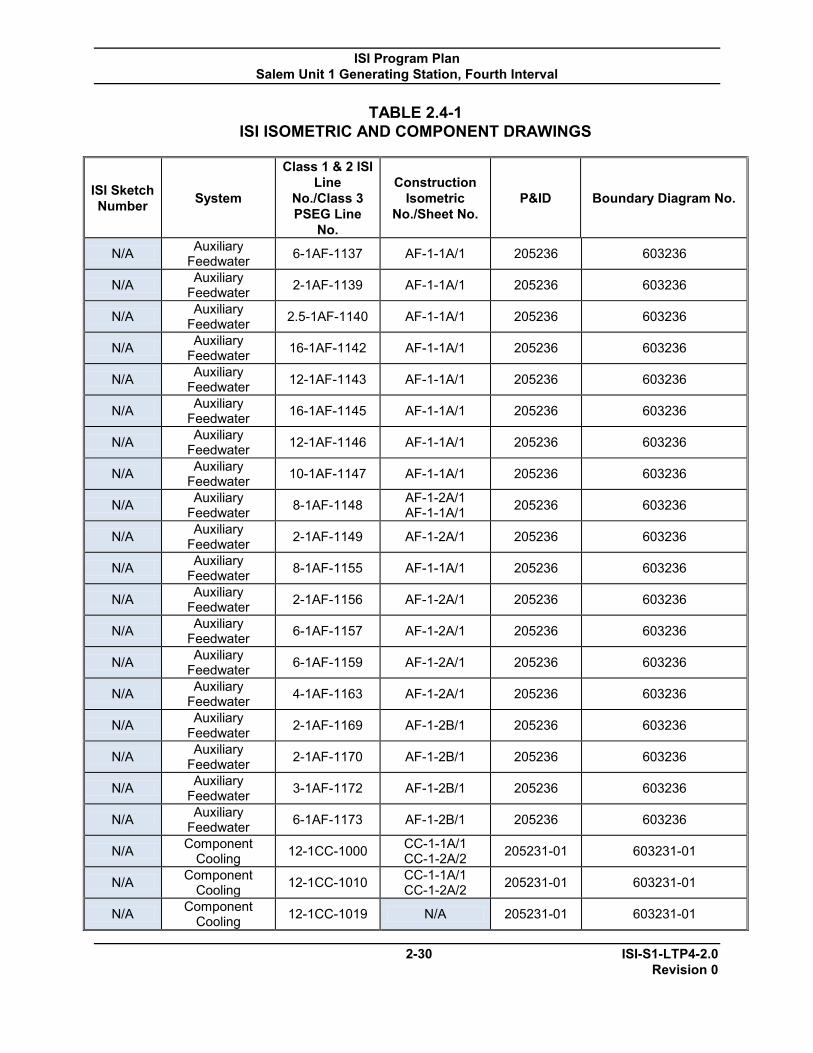
ISI Program Plan Salem Unit 1 Generating Station, Fourth Interval
2-30 ISI-S1-LTP4-2.0 Revision 0
TABLE 2.4-1 ISI ISOMETRIC AND COMPONENT DRAWINGS
ISI Sketch Number System
Class 1 & 2 ISI Line
No./Class 3 PSEG Line
No.
Construction Isometric
No./Sheet No. P&ID Boundary Diagram No.
N/A Auxiliary Feedwater 6-1AF-1137 AF-1-1A/1 205236 603236
N/A Auxiliary Feedwater 2-1AF-1139 AF-1-1A/1 205236 603236
N/A Auxiliary Feedwater 2.5-1AF-1140 AF-1-1A/1 205236 603236
N/A Auxiliary Feedwater 16-1AF-1142 AF-1-1A/1 205236 603236
N/A Auxiliary Feedwater 12-1AF-1143 AF-1-1A/1 205236 603236
N/A Auxiliary Feedwater 16-1AF-1145 AF-1-1A/1 205236 603236
N/A Auxiliary Feedwater 12-1AF-1146 AF-1-1A/1 205236 603236
N/A Auxiliary Feedwater 10-1AF-1147 AF-1-1A/1 205236 603236
N/A Auxiliary Feedwater 8-1AF-1148 AF-1-2A/1
AF-1-1A/1 205236 603236
N/A Auxiliary Feedwater 2-1AF-1149 AF-1-2A/1 205236 603236
N/A Auxiliary Feedwater 8-1AF-1155 AF-1-1A/1 205236 603236
N/A Auxiliary Feedwater 2-1AF-1156 AF-1-2A/1 205236 603236
N/A Auxiliary Feedwater 6-1AF-1157 AF-1-2A/1 205236 603236
N/A Auxiliary Feedwater 6-1AF-1159 AF-1-2A/1 205236 603236
N/A Auxiliary Feedwater 4-1AF-1163 AF-1-2A/1 205236 603236
N/A Auxiliary Feedwater 2-1AF-1169 AF-1-2B/1 205236 603236
N/A Auxiliary Feedwater 2-1AF-1170 AF-1-2B/1 205236 603236
N/A Auxiliary Feedwater 3-1AF-1172 AF-1-2B/1 205236 603236
N/A Auxiliary Feedwater 6-1AF-1173 AF-1-2B/1 205236 603236
N/A Component Cooling 12-1CC-1000 CC-1-1A/1
CC-1-2A/2 205231-01 603231-01
N/A Component Cooling 12-1CC-1010 CC-1-1A/1
CC-1-2A/2 205231-01 603231-01
N/A Component Cooling 12-1CC-1019 N/A 205231-01 603231-01

ISI Program Plan Salem Unit 1 Generating Station, Fourth Interval
2-31 ISI-S1-LTP4-2.0 Revision 0
TABLE 2.4-1 ISI ISOMETRIC AND COMPONENT DRAWINGS
ISI Sketch Number System
Class 1 & 2 ISI Line
No./Class 3 PSEG Line
No.
Construction Isometric
No./Sheet No. P&ID Boundary Diagram No.
N/A Component Cooling 16-1CC-1021 CC-1-2A/2 205231-01 603231-01
N/A Component Cooling 12-1CC-1022 CC-1-2A/2 205231-01 603231-01
N/A Component Cooling 12-1CC-1024 N/A 205231-01 603231-01
N/A Component Cooling 12-1CC-1045 CC-1-2A/2 205231-01 603231-01
N/A Component Cooling 12-1CC-1047 N/A 205231-01 603231-01
N/A Component Cooling 12-1CC-1049 CC-1-2A/2 205231-01 603231-01
N/A Component Cooling 16-1CC-1051 CC-1-2A/2 205231-01 603231-01
N/A Component Cooling 16-1CC-1066 CC-1-2A/2 205231-01 603231-01
N/A Component Cooling
16-1CC-1068
CC-1-2A/2
205231-01 205231-02
603231-01 603231-02
N/A Component Cooling 6-1CC-1091 CC-1-2A/2
CC-1-3A/2 205231-02 205231-03
603231-02 603231-03
N/A Component Cooling 12-1CC-1092 CC-1-1A/1
CC-1-2A/2 205231-01 603231-01
N/A Component Cooling 12-1CC-1123 CC-1-1A/1 205231-01 205231-01
N/A Component Cooling 12-1CC-1160 CC-1-2A/2 205231-02 603231-02
N/A Component Cooling 8-1CC-1161 CC-1-2B/1 205231-02 603231-02
N/A Component Cooling 6-1CC-1162 CC-1-2B/1 205231-02 603231-02
N/A Component Cooling 8-1CC-1167 CC-1-1C/1 205231-02 603231-02
N/A Component Cooling 8-1CC-1169 CC-1-1C/1 205231-02 603231-02
N/A Component Cooling 6-1CC-1172 CC-1-1C/1 205231-02 603231-02
N/A Component Cooling 10-1CC-1178 CC-1-1C/1 205231-02 603231-02
N/A Component Cooling 6-1CC-1183 CC-1-3A/2 205231-03 603231-03
N/A Component Cooling 10-1CC-1194 CC-1-2A/2 205231-02 603231-02
N/A Component Cooling 6-1CC-1199 CC-1-1C/1 205231-02 603231-02

ISI Program Plan Salem Unit 1 Generating Station, Fourth Interval
2-32 ISI-S1-LTP4-2.0 Revision 0
TABLE 2.4-1 ISI ISOMETRIC AND COMPONENT DRAWINGS
ISI Sketch Number System
Class 1 & 2 ISI Line
No./Class 3 PSEG Line
No.
Construction Isometric
No./Sheet No. P&ID Boundary Diagram No.
N/A Component Cooling 8-1CC-1200 CC-1-1C/1 205231-02 603231-02
N/A Component Cooling 6-1CC-1208 CC-1-1D/1
CC-1-2B/2 205231-02 603231-02
N/A Component Cooling 6-1CC-1216 CC-1-2A/2 205231-02 603231-02
N/A Component Cooling 6-1CC-1229 CC-1-2A/2
CC-1-3A/2 205231-02 603231-02
N/A Component Cooling 6-1CC-1229 CC-1-2A/2 205231-03 603231-03
N/A Component Cooling 6-1CC-1239 CC-1-2B/1 205231-02 603231-02
N/A Component Cooling 8-1CC-1254 CC-1-2B/1 205231-02 603231-02
N/A Component Cooling 16-1CC-1255 CC-1-2A/2 205231-02 603231-02
N/A Component Cooling 16-1CC-1256 CC-1-2A/2 205231-01
205231-02 603231-01 603231-02
N/A Component Cooling 6-1CC-1313 CC-1-3A/2 205231-03 603231-03
N/A Component Cooling 6-1CC-1409 CC-1-3A/2
CC-1-3B/1 205231-03 603231-03
N/A Component Cooling 6-1CC-1424
CC-1-1D/1 CC-1-2B/1
CC-1-2A/2A 205231-02 603231-02
N/A Component Cooling 14-1CC-1479 CC-1-2A/2A 205231-01 603231-01
N/A Component Cooling 14-1CC-1480 CC-1-2A/2A 205231-01 603231-01
N/A Component Cooling 14-1CC-1481 CC-1-2A/2A 205231-01 603231-01
N/A Component Cooling 14-1CC-1482 CC-1-2A/2A 205231-01 603231-01
N/A Containment Spray 10-1CS-1000 CS-1-1A/1
CS-1-2C/1 205235 603235
N/A Containment Spray 10-1CS-1003 CS-1-1A/1
CS-1-2C/1 205235 603235
N/A Containment Spray 8-1CS-1006 CS-1-1A/1
CS-1-2C/1 205235 603235
N/A Containment Spray 8-1CS-1010 CS-1-1A/1
CS-1-2C/1 205235 603235
N/A Main Steam 6-1MS-1018 MS-1-4/1 205203-01 603203-01 N/A Main Steam 8-1MS-1034 MS-1-4/1 205203-01 603203-01

ISI Program Plan Salem Unit 1 Generating Station, Fourth Interval
2-33 ISI-S1-LTP4-2.0 Revision 0
TABLE 2.4-1 ISI ISOMETRIC AND COMPONENT DRAWINGS
ISI Sketch Number System
Class 1 & 2 ISI Line
No./Class 3 PSEG Line
No.
Construction Isometric
No./Sheet No. P&ID Boundary Diagram No.
N/A Safety Injection 20-1SJ-1004 RH-1-2A/1 RH-1-2B/2
205234-01 205234-02
603234-01 603234-02
N/A Safety Injection 12-1SJ-1005 RH-1-2A/1 RH-1-2B/2
205234-02 205234-03
603234-02 603234-03
N/A Safety Injection 8-1SJ-1007 RH-1-2A/1 205234-01 603234-01 N/A Safety Injection 8-1SJ-1009 RH-1-2B/1 205234-02 603234-02 N/A Safety Injection 8-1SJ-1010 RH-1-2A/1 205234-03 603234-03
N/A Safety Injection 8-1SJ-1011 RH-1-2A/1 205234-01/-04 603234-01/-04
N/A Safety Injection 12-1SJ-1094 RH-1-2A/1 RH-1-2B/1
205235 205234-01/-
04
603235 603234-01/-04
N/A Service Water 20-1SW-1000 SW-17H/1 205242 603242 N/A Service Water 20-1SW-1001 SW-17H/1 205242 603242 N/A Service Water 20-1SW-1002 SW-17H/1 205242 603242 N/A Service Water 20-1SW-1003 SW-17H/1 205242 603242 N/A Service Water 30-1SW-1004 SW-17H/1 205242-01 603242-01 N/A Service Water 20-1SW-1005 SW-17H/1 205242 603242 N/A Service Water 20-1SW-1006 SW-17H/1 205242 603242 N/A Service Water 6-1SW-1013 SW-1-7B/3 205242 603242 N/A Service Water 6-1SW-1016 SW-1-7B/3 205242 603242 N/A Service Water 6-1SW-1019 SW-1-7B/3 205242 603242 N/A Service Water 8-1SW-1020 SW-1-7B/4 205242 603242 N/A Service Water 10-1SW-1021 SW-1-7B/4 205242 603242
N/A Service Water 30-1SW-1067 SW-1-7H/1 205242-01 205242-02
603242-01 603242-02
N/A Service Water 30-1SW-1068 SW-17K/1 205242-02 603242-02 N/A Service Water 20-1SW-1069 SW-17K/1 205242-02 603242-02 N/A Service Water 20-1SW-1070 SW-17K/1 205242-02 603242-02 N/A Service Water 20-1SW-1071 SW-17K/1 205242-02 603242-02 N/A Service Water 20-1SW-1072 SW-17K/1 205242-02 603242-02 N/A Service Water 20-1SW-1073 SW-17K/1 205242-02 603242-02 N/A Service Water 20-1SW-1074 SW-17K/1 205242-02 603242-02 N/A Service Water 20-1SW-1078 SW-17K/1 205242 603242 N/A Service Water 6-1SW-1083 SW-1-7B/3 205242 603242 N/A Service Water 8-1SW-1084 205242 603242 N/A Service Water 10-1SW-1085 SW-1-7B/4 205242 603242 N/A Service Water 6-1SW-1098 SW-1-7B/3 205242 603242 N/A Service Water 6-1SW-1101 SW-1-7B/3 205242 603242
N/A Service Water 30-1SW-1136 SW-1-7K/1 SW-1-7H/1
205242-01 205242-02
603242-01 603242-02
N/A Service Water 30-1SW-1137 SW-1-7H/1 205242 603242 N/A Service Water 24-1SW-1149 SW-1-7H/1 205242 603242
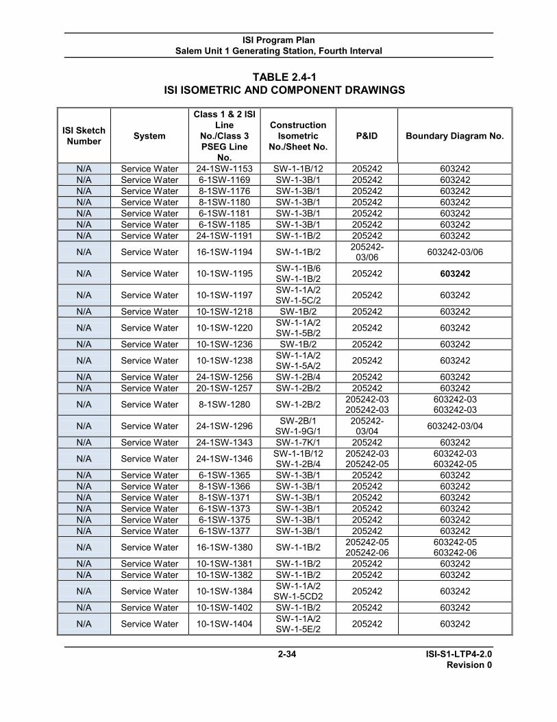
ISI Program Plan Salem Unit 1 Generating Station, Fourth Interval
2-34 ISI-S1-LTP4-2.0 Revision 0
TABLE 2.4-1 ISI ISOMETRIC AND COMPONENT DRAWINGS
ISI Sketch Number System
Class 1 & 2 ISI Line
No./Class 3 PSEG Line
No.
Construction Isometric
No./Sheet No. P&ID Boundary Diagram No.
N/A Service Water 24-1SW-1153 SW-1-1B/12 205242 603242 N/A Service Water 6-1SW-1169 SW-1-3B/1 205242 603242 N/A Service Water 8-1SW-1176 SW-1-3B/1 205242 603242 N/A Service Water 8-1SW-1180 SW-1-3B/1 205242 603242 N/A Service Water 6-1SW-1181 SW-1-3B/1 205242 603242 N/A Service Water 6-1SW-1185 SW-1-3B/1 205242 603242 N/A Service Water 24-1SW-1191 SW-1-1B/2 205242 603242
N/A Service Water 16-1SW-1194 SW-1-1B/2 205242-03/06 603242-03/06
N/A Service Water 10-1SW-1195 SW-1-1B/6 SW-1-1B/2 205242 603242
N/A Service Water 10-1SW-1197 SW-1-1A/2 SW-1-5C/2 205242 603242
N/A Service Water 10-1SW-1218 SW-1B/2 205242 603242
N/A Service Water 10-1SW-1220 SW-1-1A/2 SW-1-5B/2 205242 603242
N/A Service Water 10-1SW-1236 SW-1B/2 205242 603242
N/A Service Water 10-1SW-1238 SW-1-1A/2 SW-1-5A/2 205242 603242
N/A Service Water 24-1SW-1256 SW-1-2B/4 205242 603242 N/A Service Water 20-1SW-1257 SW-1-2B/2 205242 603242
N/A Service Water 8-1SW-1280 SW-1-2B/2 205242-03 205242-03
603242-03 603242-03
N/A Service Water 24-1SW-1296 SW-2B/1 SW-1-9G/1
205242-03/04 603242-03/04
N/A Service Water 24-1SW-1343 SW-1-7K/1 205242 603242
N/A Service Water 24-1SW-1346 SW-1-1B/12 SW-1-2B/4
205242-03 205242-05
603242-03 603242-05
N/A Service Water 6-1SW-1365 SW-1-3B/1 205242 603242 N/A Service Water 8-1SW-1366 SW-1-3B/1 205242 603242 N/A Service Water 8-1SW-1371 SW-1-3B/1 205242 603242 N/A Service Water 6-1SW-1373 SW-1-3B/1 205242 603242 N/A Service Water 6-1SW-1375 SW-1-3B/1 205242 603242 N/A Service Water 6-1SW-1377 SW-1-3B/1 205242 603242
N/A Service Water 16-1SW-1380 SW-1-1B/2 205242-05 205242-06
603242-05 603242-06
N/A Service Water 10-1SW-1381 SW-1-1B/2 205242 603242 N/A Service Water 10-1SW-1382 SW-1-1B/2 205242 603242
N/A Service Water 10-1SW-1384 SW-1-1A/2 SW-1-5CD2 205242 603242
N/A Service Water 10-1SW-1402 SW-1-1B/2 205242 603242
N/A Service Water 10-1SW-1404 SW-1-1A/2 SW-1-5E/2 205242 603242

ISI Program Plan Salem Unit 1 Generating Station, Fourth Interval
2-35 ISI-S1-LTP4-2.0 Revision 0
TABLE 2.4-1 ISI ISOMETRIC AND COMPONENT DRAWINGS
ISI Sketch Number System
Class 1 & 2 ISI Line
No./Class 3 PSEG Line
No.
Construction Isometric
No./Sheet No. P&ID Boundary Diagram No.
N/A Service Water 6-1SW-1422 SW-1-1J/1 SW-1-1B/3 205242 603242
N/A Service Water 20-1SW-1493 SW-1-2B/4 SW-1-1B/2 205242-03 603242-03
N/A Service Water 20-1SW-1496 SW-1-2B/2 SW-1-9H/1
205242-04 205242-05
603242-04 603242-05
N/A Service Water 8-1SW-1498 SW-1-3B/1 205242 603242 N/A Service Water 8-1SW-1502 SW-1-1B-12 205242 603242 N/A Service Water 8-1SW-1503 SW-1-1B-12 205242 603242 N/A Service Water 8-1SW-1504 SW-1-1B-12 205242 603242 N/A Service Water 8-1SW-1505 SW-1-1B-12 205242 603242
N/A Service Water 24-1SW-1506 SW-1-1B-12 205242-03 205242-06
603242-03 603242-06
N/A Service Water 24-1SW-1507 SW-1-1B-12 205242-03 205242-05
603242-03 603242-05
N/A Service Water 6-1SW-1541 SW-1-3B/1 205242 603242 N/A Service Water 8-1SW-1542 SW-1-3B/1 205242 603242 N/A Service Water 6-1SW-1545 SW-1-3B/1 205242 603242 N/A Service Water 6-1SW-1546 SW-1-3B/1 205242 603242 N/A Service Water 6-1SW-1549 SW-1-3B/1 205242 603242 N/A Service Water 6-1SW-1550 SW-1-3B/1 205242 603242 N/A Service Water 8-1SW-1551 SW-1-3B/1 205242 603242 N/A Service Water 6-1SW-1556 SW-1-3B/1 205242 603242 N/A Service Water 8-1SW-1557 SW-1-3B/1 205242 603242 N/A Service Water 6-1SW-1589 SW-1-1B/3 205242 603242
N/A Service Water 10-1SW-1597 SW-1-1A/2 SW-1-5E/2 205242 603242
N/A Service Water 10-1SW-1599 SW-1-1B/2 205242 603242
N/A Service Water 10-1SW-1619 SW-1-1A/2 SW-1-5D/2 205242 603242
N/A Service Water 10-1SW-1622 SW-1-1B/2 205242 603242
N/A Service Water 10-1SW-1640 SW-1-1A/2 SW-1-5C/2 205242 603242
N/A Service Water 10-1SW-1642 SW-1-1B/7 205242 603242
N/A Service Water 10-1SW-1643 SW-1-1B/2 205242-06 205242-05
603242-06 603242-05
N/A Service Water 10-1SW-1657 SW-1-1B/2 205242 603242 N/A Service Water 10-1SW-1658 SW-1-1B/4 205242 603242
N/A Service Water 10-1SW-1664 SW-1-1A/2 SW-1-5B/2 205242 603242
N/A Service Water 10-1SW-1666 SW-1-1B/2 SW-1-1B/1A 205242 603242
N/A Service Water 10-1SW-1684 SW-1-1A/2 SW-1-5A/2 205242 603242

ISI Program Plan Salem Unit 1 Generating Station, Fourth Interval
2-36 ISI-S1-LTP4-2.0 Revision 0
TABLE 2.4-1 ISI ISOMETRIC AND COMPONENT DRAWINGS
ISI Sketch Number System
Class 1 & 2 ISI Line
No./Class 3 PSEG Line
No.
Construction Isometric
No./Sheet No. P&ID Boundary Diagram No.
N/A Service Water 10-1SW-1685 SW-1-1B/2 205242 603242 N/A Service Water 6-1SW-1860 SW-1-9F/1 205242 603242 N/A Service Water 8-1SW-1863 SW-1-9F/1 205242 603242 N/A Service Water 6-1SW-1897 SW-1-9F/1 205242 603242 N/A Service Water 8-1SW-1898 SW-1-9F/1 205242 603242 N/A Service Water 6-1SW-1899 SW-1-9F/1 205242 603242 N/A Service Water 6-1SW-1901 SW-1-9F/1 205242 603242 N/A Service Water 6-1SW-1903 SW-1-1B/1A 205242 603242 N/A Service Water 6-1SW-1905 SW-1-1B/1A 205242 603242 N/A Service Water 8-1SW-1907 SW-1-1B/1A 205242 603242 N/A Service Water 10-1SW-1908 SW-1-1B/1A 205242 603242 N/A Service Water 8-1SW-1915 SW-1-1B/1A 205242 603242 N/A Service Water 16-1SW-1938 SW-1-1B/1A 205242 603242 N/A Service Water 14-1SW-1955 SW-1-9J/1 205242 603242 N/A Service Water 14-1SW-1956 SW-1-9J/1 205242 603242 N/A Service Water 14-1SW-1957 SW-1-9J/1 205242 603242 N/A Service Water 14-1SW-1958 SW-1-9J/1 205242 603242 N/A Service Water 14-1SW-1959 SW-1-9K/1 205242 603242 N/A Service Water 14-1SW-1960 SW-1-9K/1 205242 603242 N/A Service Water 14-1SW-1962 SW-1-9K/1 205242 603242 N/A Service Water 12-1SW-1974 SW-1-7J/1 205242-02 603242-02 N/A Service Water 8-1SW-1975 SW-1-7J/1 205242 603242 N/A Service Water 12-1SW-1980 SW-1-7J/1 205242 603242 N/A Service Water 8-1SW-1981 SW-1-7J/1 205242 603242 N/A Service Water 8-1SW-1986 SW-1-3B/1 205242 603242 N/A Service Water 10-1SW-1987 SW-1-1B/1A 205242 603242
N/A Service Water Not Identified SW-1-15A SW-1-15B 205242-06 603242-06
N/A Service Water Not Identified SW-1-14A SW-1-14B 205242-07 603242-07
N/A Service Water Not Identified SW-1-12A SW-1-12B 205242-05 603242-05
N/A Service Water Not Identified SW-1-11A SW-1-11B 205242-07 603242-07
N/A Liquid Rad Waste 8-1WL-1188 LW-1-4/1 205234-01/-
04 603234-01/-04

ISI Program Plan Salem Unit 1 Generating Station, Fourth Interval
2-37 ISI-S1-LTP4-2.0 Revision 0
2.5 Technical Approach and Positions
The requirements of ASME Section XI are not easily interpreted in some instances. ASME Section XI provides a method of obtaining interpretations, but these generally are in response to generic code application, and do not necessarily address specific site situations. Salem has reviewed general licensing/regulatory requirements and industry practices to determine the practical methods of implementing the Code requirements for the site. The Technical Approach and Position (TAP) documents contained in this section have been provided to clarify Salem's implementation of ASME Section XI requirements, when a difficult code interpretation is encountered for a site specific situation. TAPs may be added throughout the interval, when required. An index which summarizes each technical approach and position is included in Table 2.5-1.

ISI Program Plan Salem Unit 1 Generating Station, Fourth Interval
2-38 ISI-S1-LTP4-2.0 Revision 0
TABLE 2.5-1
TECHNICAL APPROACH AND POSITIONS INDEX
Position Number
Revision Date2
Status1 Description of Technical Approach
SM1-I4T-01
0 05/20/2011
Active (SPT) Extended boundary Class 1 System Pressure Testing
SM1-I4T-02
0 05/20/2011
Active (ISI) When adding items, welds, or component supports during the interval.
Note 1: Technical Approach and Position Status Options: Active - Current ISI Program technical approach and position is being utilized at Salem Unit 1; Deleted - Technical approach and position is no longer being utilized at Salem Unit 1.
Note 2: The revision listed is the latest revision of the subject technical approach and position. The date noted in the second column is the date of the ISI Program Plan revision when the technical approach and position was incorporated into the document.

lSI Program Plan Salem Unit 1 Generating Station, Fourth Interval
TECHNICAL APPROACH AND POSITION
SM1-14T-01
COMPONENT IDENTIFICATION:
Code Class: Reference: Examination Category: Item Number: Description:
Component Number:
CODE REQUIREMENT:
1 IWB-5222 (a) B-P B15.10 System Leakage Testing of Class 1 Components Not at or Near the End of the Inspection Interval Class 1 Pressure Retaining Components Beyond the Second Closed Valve
IWB-5222(a) states, "The pressure retaining boundary during the system leakage test shal/ correspond to the reactor coolant boundary, with aI/ valves in the position required for normal reactor operation startup. The visual examination shal/, however, extend to and include the second closed valve at the boundary extremity."
POSITION:
IWB-5222(a) limits the visual examination for Class 1 leakage tests not associated with the test conducted at or near the end of the interval to Class 1 components up to the second closed valve. Salem Unit 1 has Class 1 components beyond this second closed valve fol/owing the original design classification criteria for the plant. The code addresses these components in IWB-5222(b) for the System Leakage Test conducted at or near the end of the Inspection Interval, but not for System Leakage Testing conducted after refueling outages at other times. Not including the Class 1 components for examination beyond the second closed valve appears to be non-conservative when conSidering the frequency of visual examination performed on other Class 1 components (every refueling outage) and Class 2 and 3 components (every period).
It is Salem Unit 1's position that the visual examination be conducted on aI/ Class 1 pressure retaining components including those beyond the second closed valve when meeting IWB-5222(a). This position will maintain the same frequency of examination for aI/ Class 1 components and will address the extended Class 1 classification at Salem Unit 1, conservatively.
2-39 ISI-S1-L TP4-2.0 Revision 0

lSI Program Plan Salem Unit 1 Generating Station, Fourth Interval
TECHNICAL APPROACH AND POSITION
SM1·14T .. 02
COMPONENT IDENTIFICATION:
Code Class: Reference: Examination Category: Item Number: Description:
Component Number:
CODE REQUIREMENT:
Class 1, 2 and 3 IWB-2412(b), IWC-2412(b), IWD-2412(b) and IWF-2410(c) As applicable As applicable When adding items, welds, or component supports during the interval. As applicable
IWB-2412(b) states, "If items or welds are added to the Inspection Program, during the service lifetime of a plant, examination shall be scheduled as follows:
(1) When items or welds are added during the first period of an interval, at least 25% of the examinations required by the applicable Examination Category and Item Number for the added items or welds shall be performed during each of the second and third periods of that interval. Alternatively, if deferral of the examinations is permitted for the Examination Category and Item Number, the second period examinations may be deferred to the third period and at least 50% of the examinations required by the applicable Examination Category and Item Number for the added items or welds shall be performed during the third period of that interval.
(2) When items or welds are added during the second period of an interval, at least 25% of the examinations required by the applicable Examination Category and Item Number for the added items or welds shall be performed during the third period of that interval.
(3) When items or welds are added during the third period of an interval, examinations shall be scheduled in accordance with IWB-2412(a) for successive intervals."
IWC-2412(b) states, "If items or welds are added to the Inspection Program, during the service lifetime of a plant, examination shall be scheduled as follows:
(1) When items or welds are added during the first period of an interval, at least 25% of the examinations required by the applicable Examination Category and Item Number for the added items or welds shall be performed during each of the second and third periods of that interval.
(2) When items or welds are added during the second period of an interval, at least 25% of the examinations required by the applicable Examination Category and Item
2-40 ISI-S1-LTP4-2.0 Revision 0

ISI Program Plan Salem Unit 1 Generating Station, Fourth Interval
2-41 ISI-S1-LTP4-2.0 Revision 0
Number for the added items or welds shall be performed during the third period of that interval.
(3) When items or welds are added during the third period of an interval, examinations shall be scheduled in accordance with IWC-2412(a) for successive intervals.‖
IWD-2412(b) states, ―If items are added to the Inspection Program, during the service lifetime of a plant, examination shall be scheduled as follows:
(1) When items are added during the first period of an interval, at least 25% of the examinations required by the applicable Examination Category and Item Number for the added items shall be performed during each of the second and third periods of that interval.
(2) When items are added during the second period of an interval, at least 25% of the examinations required by the applicable Examination Category and Item Number for the added items shall be performed during the third period of that interval.
(3) When items are added during the third period of an interval, examinations shall be scheduled in accordance with IWD-2412(a) for successive intervals.‖
IWF-2410(c) states, ―If component supports are added to the Inspection Program, during the service lifetime of a plant, examination shall be scheduled as follows:
(1) When component supports are added during the first period of an interval, at least 25% of the examinations required by the applicable Examination Category and Item Number for the added component supports shall be performed during each of the second and third periods of that interval.
(2) When component supports are added during the second period of an interval, at least 25% of the examinations required by the applicable Examination Category and Item Number for the added component supports shall be performed during the third period of that interval.
(3) When component supports are added during the third period of an interval, examinations shall be scheduled in accordance with IWF-2410(b) for successive intervals.‖
POSITION:
It is Salem Unit 1‘s position that the addition of items, welds or component supports needs further definition to appropriately apply the referenced code requirements. Salem
ISI Program Plan Salem Unit 1 Generating Station, Fourth Interval
2-42 ISI-S1-LTP4-2.0 Revision 0
makes a distinction between new added items, welds or component supports, and a replacement to an existing item, weld or component support. For example:
(a) A new train is added to an existing two train system such that three trains now exist. The modification added 100 new welds and 25 component supports. The code paragraphs above would apply in this scenario, as applicable.
(b) Two new replacement welds are made in the installation of a replacement valve. No increase in welds occurs in this replacement activity. The code paragraphs above would not apply, and there would be no impact on the ISI scheduling normally, however if the item, weld, or component support replaced was scheduled for ISI in the same outage, the schedule shall be modified by either replacing the selected item, weld, or component support with an acceptable replacement or deferring the examination to the next outage or subsequent outage. Code Category period percentages must be met, if deferred. Preservice examination of a replacement may not be used for inservice examination.
(c) A repair/replacement activity modifies a support. What had been single directional support is now a multi-directional support. The code paragraphs above do not apply. This activity may impact the distribution of selected supports in a system and their function types. The support selection distribution needs to be verified as still being appropriate and modified accordingly, if required. This may require a component support selection change for ISI. Code Category period percentages must still be met.
(d) Any addition, removal, or modification of welds in the RI-ISI program will be addressed as part of the periodic reevaluation requirements of Code Case N-578-1.
When replacing major components, such as steam generators; Salem has taken the position that the new component contains new added items and welds. They may or may not be equivalent in number or description to the original component. This is not a normal weld for weld or item for item replacement activity described in (b) above. As such, Salem shall apply the code paragraphs above for this type activity, as applicable.
ISI Program Plan Salem Unit 1 Generating Station Fourth Interval
3-1 ISI-S1-LTP4-3.0 Revision 0
3.0 COMPONENT ISI PLAN
The Salem Unit 1 Component ISI Plan includes ASME Section XI nonexempt pressure retaining components such as welds, piping structural elements, pressure retaining bolting, attachment welds, pump casings, valve bodies, and vessels that are ISI Class 1, 2, and 3 and meet the criteria of IWA-1300 in ASME Section XI. These components are identified on the ASME Section XI ISI Drawings listed in Section 2.3, Table 2.3-2. Procedure ER-AA-330-002, “Inservice Inspection of Welds and Components”, implements the ASME Section XI Welds and Components ISI Plan. This Component ISI Plan also includes component augmented inservice inspection program information specified by documents other than ASME Section XI as referenced in Section 2.2 of this document.
The services of an Authorized Inspection Agency (AIA) are to be used when performing ASME Section XI Component ISI examinations. All ASME Section XI Component ISI examinations are subject to verification by the ANII. For all ASME Section XI Component ISI examinations ensure that: (IWA-1500, IWA-2110, and IWA-2130)
(a) The ANII is given opportunity to review the Component ISI Plan (and revisions), and as necessary the implementation schedule.
(b) Provisions are made to ensure the ANII is permitted to verify examinations and review records.
(c) The ANII is to be informed of the progress of examination activities and provided access so that necessary inspections may be performed.
3.1 Nonexempt ISI Class Components
The ISI Class 1, 2 and 3 components subject to examination are those that are not exempted under the criteria of Subarticles IWB-1220, IWC-1220 or IWD-1220 in the 2004 Edition of ASME Section XI.
3.1.1 Identification of ISI Class 1, 2, and 3 Nonexempt Components
ISI Class 1 and 2 components are identified on the ISI Isometric (Weld Identification) and ISI Component Drawings listed in Section 2.4, Table 2.4-1. Station construction isometrics and plant P&ID drawings are used to locate and identify ISI Class 3 components. These drawings are also listed in Section 2.4, Table 2.4-1.
3.2 Exempt ISI Class 1 Components (IWB-1220)
The following ISI Class 1 exemptions apply at Salem Unit 1from the volumetric and surface examination requirements of IWB-2500:

ISI Program Plan Salem Unit 1 Generating Station Fourth Interval
3-2 ISI-S1-LTP4-3.0 Revision 0
(a) Components that are connected to the reactor coolant system and are part of the reactor coolant pressure boundary, and that are of such size and shape so that upon postulated rupture the resulting flow of coolant from the reactor coolant system under normal plant operating conditions is within the capacity of makeup systems that are operable from on-site emergency power. The emergency core cooling systems are excluded from this calculation of make-up capacity. [Salem Unit 1 has determined this size exemption to be 3/8 inch. This is the actual orifice size in a component opening.]
(b)(1) Components and piping segments NPS 1 and smaller, except for steam generator tubing.
(b)(2) Components and piping segments which have one inlet and one outlet, both of which are NPS 1 and smaller.
(b)(3) Components (for heat exchangers, the shell side and tube side may be considered separate components) and piping segments which have multiple inlets and multiple outlets whose cumulative pipe cross-sectional area does not exceed the cross-sectional area defined by the OD of NPS 1 pipe. [Inlet and outlet cumulative totals treated separately similar to (b)(2) above.]
(c) Reactor Vessel head connections and associated piping, NPS 2 and smaller, made inaccessible by control rod drive penetrations.
(d) Welds or portions of welds that are inaccessible due to being encased in concrete, buried underground, located inside a penetration, or encapsulated by guard pipe.
3.3 Exempt ISI Class 2 Components within Residual heat Removal (RHR), Emergency Core Cooling (ECC), and Containment Heat Removal (CHR) Systems or Portions of Systems (IWC-1221)
The following ISI Class 2 exemptions apply at Salem Unit 1 for components within RHR, ECC, and CHR systems or portions of systems from the volumetric and surface examination requirements of IWC-2500:
(a) For systems, except high pressure safety injection systems in pressurized water reactor plants:
(1) Components and piping segments NPS 4 and smaller.
(2) Components and piping segments which have one inlet and one outlet, both of which are NPS 4 and smaller.
(3) Components (for heat exchangers, the shell side and tube side
ISI Program Plan Salem Unit 1 Generating Station Fourth Interval
3-3 ISI-S1-LTP4-3.0 Revision 0
may be considered separate components) and piping segments which have multiple inlets or outlets, whose cumulative pipe cross-sectional area does not exceed the cross-sectional area defined by the OD of NPS 4 pipe. [Inlet and outlet cumulative totals treated separately similar to (a)(2) above.]
(b) For high pressure safety injection systems in pressurized water reactor plants:
(1) Components and piping segments NPS 1½ and smaller.
(2) Components and piping segments which have one inlet and one outlet, both of which are 1½ NPS and smaller.
(3) Components (for heat exchangers, the shell side and tube side may be considered separate components) and piping segments which have multiple inlets or outlets, whose cumulative pipe cross-sectional area does not exceed the cross-sectional area defined by the OD of NPS 1½ pipe. [Inlet and outlet cumulative totals treated separately similar to (b)(2) above.]
(c) Vessels, piping, pumps, valves, other components, and component connections of any size in statically pressurized, passive (i.e., no pumps) safety injection systems (Salem’s statically pressurized accumulator tanks and associated system) of pressurized water reactor plants.
(d) Piping and other components of any size beyond the last shutoff valve in open ended portions of systems that do not contain water during normal plant operating conditions.
3.4 Exempt ISI Class 2 Components Other Than RHR, ECC, and CHR Systems or Portions of Systems (IWC-1222)
The following ISI Class 2 exemptions apply at Salem Unit 1 for components within systems or portions of systems other than RHR, ECC, and CHR systems from the volumetric and surface examination requirements of IWC-2500:
(a) For systems except auxiliary feedwater systems in pressurized water reactor plants:
(1) Components and piping segments NPS 4 and smaller.
(2) Components and piping segments which have one inlet and one outlet, both of which are NPS 4 and smaller.

ISI Program Plan Salem Unit 1 Generating Station Fourth Interval
3-4 ISI-S1-LTP4-3.0 Revision 0
(3) Components (for heat exchangers, the shell side and tube side may be considered separate components) and piping segments which have multiple inlets or outlets, whose cumulative pipe cross-sectional area does not exceed the cross-sectional area defined by the OD of NPS 4 pipe. [Inlet and outlet cumulative totals treated separately similar to (a)(2) above.]
(b) For auxiliary feedwater systems in pressurized water reactor plants:
(1) Components and piping segments NPS 1½ and smaller.
(2) Components and piping segments which have one inlet and one outlet, both of which are 1½ NPS and smaller.
(3) Components (for heat exchangers, the shell side and tube side may be considered separate components) and piping segments which have multiple inlets or outlets, whose cumulative pipe cross-sectional area does not exceed the cross-sectional area defined by the OD of NPS 1½ pipe. [Inlet and outlet cumulative totals treated separately similar to (b)(2) above.]
(c) Vessels, piping, pumps, valves, other components, and component connections of any size in systems or portions of systems that operate (when the system function is required) at a pressure equal to or less than 275 psig and at a temperature equal to or less than 200ºF.
(d) Piping and other components of any size beyond the last shutoff valve in open ended portions of systems that do not contain water during normal plant operating conditions.
3.5 Exempt ISI Class 2 Inaccessible Welds (IWC-1223)
Welds or portions of welds at Salem Unit 1 that are inaccessible due to being encased in concrete, buried underground, located inside a penetration, or encapsulated by guard pipe are exempt from the volumetric and surface examination requirements of IWC-2500.
3.6 Exempt ISI Class 3 Components
The following components or portions of components are exempted from the VT-1 visual examination requirements of IWD-2500.
(a) Components and piping segments NPS 4 and smaller.
(b) Components and piping segments which have one inlet and one outlet, both of which are NPS 4 and smaller.

ISI Program Plan Salem Unit 1 Generating Station Fourth Interval
3-5 ISI-S1-LTP4-3.0 Revision 0
(c) Components (for heat exchangers, the shell side and tube side may be considered separate components) and piping segments which have multiple inlets or outlets, whose cumulative pipe cross-sectional area does not exceed the cross-sectional area defined by the OD of NPS 4 pipe. [Inlet and outlet cumulative totals treated separately similar to (b) above.]
(d) Components that operate at a pressure of 275 psig or less and at a temperature of 200ºF or less in systems (or portions of systems) whose function is not required in support of reactor residual heat removal, containment heat removal, and emergency core cooling.
(e) welds or portions of welds that are inaccessible due to being encased in concrete, buried underground, located inside a penetration, or encapsulated by guard pipe.
3.7 Inspection Program B
The required percentage of examinations in each Examination Category shall be completed in accordance with Tables IWB-2412-1, IWC-2412-1, IWD-2412-1, and -2410 in Code Case N-578-1, as applicable. Exceptions to this requirement are detailed in IWB-2412, IWC-2412, IWD-2412, and -2410, as applicable.
If there are less than three items or welds to be examined in an Examination Category, the items or welds may be examined in any two periods, or in any one period if there is only one item or weld in lieu of the percentage requirements above.
3.8 Risk-Informed Examination Requirements
The Salem Unit 1 RI-ISI Program has been developed in accordance with the EPRI methodology contained in EPRI TR-112657, "Risk-Informed In-service Inspection Evaluation Procedure." It was approved for use at Salem Unit 1 during the first inspection period of the Third Ten-year Inspection Interval and is still applicable for the Fourth ISI Interval. The RI-ISI program has been updated consistent with the intent of NEI-04-05 and continues to meet EPRI TR-112657 and Regulatory Guide 1.174 risk acceptance criteria. PSEG will continue to implement the Risk-Informed Inservice Inspection Program in accordance with ASME Code Case N-578-1, "Risk-Informed Requirements for Class 1, 2, and 3 Piping, Method B, Section XI, Division 1," as an alternative to Categories B-F, B-J, C-F-1, and C-F-2 for piping welds. The ultrasonic examination volume to be used based on degradation mechanism and component configuration will be the examination figures specified in Section 4 of EPRI TR-112657. The ultrasonic examination procedures, equipment, and personnel used to

ISI Program Plan Salem Unit 1 Generating Station Fourth Interval
3-6 ISI-S1-LTP4-3.0 Revision 0
detect and size flaws in piping welds will be qualified by performance demonstration in accordance with ASME Section XI Appendix VIII, "Performance Demonstration for Ultrasonic Examination Systems." The volumetric scanning will be in both the axial and circumferential directions to detect flaws in these orientations. As part of the RI-ISI living program update, the delta risk assessment was re-evaluated and was determined to continue to meet the delta risk acceptance criteria of EPRI TR-112657. This update is based on the most recent Salem PRA, which has been peer reviewed to Regulatory Guide 1.200, Rev 1 and updated accordingly. The PRA has been determined to be adequate for this application. Piping structural elements may be excluded from examination (other than pressure testing) under the RI-ISI Program if the only degradation mechanism present is the Flow Accelerated Corrosion (FAC). These piping structural elements will remain part of the FAC Program, which already performs “for cause” inspections to detect this degradation mechanism. Piping structural elements susceptible to FAC along with another degradation mechanism (e.g., thermal fatigue) are retained as part of the RI-ISI scope and are included in the element selection for the purpose of performing exams to detect the additional degradation mechanism.
Thin wall welds that were excluded from volumetric examination under ASME Section XI rules per Table IWC-2500-1 are included in the element scope that is potentially subject to RI-ISI examination at Salem Unit 1. The RI-ISI Program element examinations are performed in accordance with Relief Request S1-I4R-105.
3.9 Successive Inspections
3.9.1 Successive Inspections on RI-ISI structural elements will be performed in accordance with -2420 of Code Case N-578-1 which includes the following criteria:
(a) If piping structural elements are accepted for continued service
by analytical evaluation in accordance with -3200 (N-578-1), the areas containing the flaws or relevant conditions shall be reexamined during the next three inspection periods referenced in the schedule.
(b) If the reexaminations of 3.9.1(a) reveal that flaws or relevant
conditions remain essentially unchanged for three successive inspection periods, the piping examination schedule may revert to the original schedule of successive inspections.

ISI Program Plan Salem Unit 1 Generating Station Fourth Interval
3-7 ISI-S1-LTP4-3.0 Revision 0
3.9.2 Successive Inspections on Class 1 components (non-RI-ISI) will be performed in accordance with IWB-2420 which includes the following criteria:
(a) If a component is accepted for continued service in
accordance with IWB-3132.3 or IWB-3142.4, the areas containing flaws or relevant conditions shall be reexamined during the next three inspection periods listed in the schedule of the inspection program of IWB-2400. Alternatively, acoustic emission may be used to monitor growth of existing flaws in accordance with IWA-2234.
(b) If the reexaminations required by 3.9.2(a) reveal that the
flaws or relevant conditions remain essentially unchanged for three successive inspection periods, the component examination schedule may revert to the original schedule of successive inspections.
(c) If welded attachments are examined as a result of identified
component support deformation, and the results of these examinations exceed the acceptance standards of Table IWB-3410-1, successive examinations shall be performed, if determined necessary, based on an evaluation by PSEG.
3.9.3 Successive Inspections on Class 2 components (non-RI-ISI) will be performed in accordance with IWC-2420 which includes the following criteria:
(a) If a component is accepted for continued service in
accordance with IWC-3122.3 or IWC-3132.3, the areas containing flaws or relevant conditions shall be reexamined during the next inspection period listed in the schedule of the inspection program of IWC-2400. Alternatively, acoustic emission may be used to monitor growth of existing flaws in accordance with IWA-2234.
(b) If the reexaminations required by 3.9.3(a) reveal that the
flaws or relevant conditions remain essentially unchanged for the next inspection period, the component examination schedule may revert to the original schedule of successive inspections.
(c) If welded attachments are examined as a result of identified
component support deformation, and the results of these examinations exceed the acceptance standards of Table

ISI Program Plan Salem Unit 1 Generating Station Fourth Interval
3-8 ISI-S1-LTP4-3.0 Revision 0
IWC-3410-1, successive examinations shall be performed, if determined necessary, based on an evaluation by PSEG.
3.9.4 As an alternative for Class 1 and 2 vessels, the requirements of Code Case N-526 may be used to eliminate successive examinations. The requirements of Code Case N-526 are outlined below.
(a) The flaw is characterized as subsurface in accordance with
Figure 1 of Code Case N-526. (b) The NDE technique and evaluation that detected and
characterized the flaw, with respect to both sizing and location, shall be documented in the flaw evaluation report.
(c) The vessel containing the flaw is acceptable for continued
service in accordance with IWB-3600, and the flaw is demonstrated acceptable for the intended service life of the vessel.
3.9.5 Successive Inspections on Class 3 components will be performed in
accordance with IWD-2420 which includes the following criteria: (a) If components are accepted for continued service by
evaluation in accordance with IWD-3000, the areas containing flaws or relevant conditions shall be reexamined during the next inspection period listed in the schedule of the inspection program of IWD-2400.
(b) If the reexaminations required by 3.9.5(a) reveal that the
flaws or relevant conditions remain essentially unchanged for the next inspection period, the component examination schedule may revert to the original schedule of successive inspections.
(c) If welded attachments are examined as a result of identified
component support deformation, and the results of these examinations exceed the acceptance standards of IWD-3000, successive examinations shall be performed, if determined necessary, based on an evaluation by PSEG.
3.9.6 Successive Inspections on Augmented examinations will be
performed in accordance with its’ Augmented Program requirements document.

ISI Program Plan Salem Unit 1 Generating Station Fourth Interval
3-9 ISI-S1-LTP4-3.0 Revision 0
3.10 Additional Examinations
In general additional examinations are required when an examination exceeds the nondestructive examination (Volumetric, Surface, or Visual) acceptance criteria found in Tables IWB-3410-1, or IWC-3410-1, or paragraphs IWD-3400, or -3000 (N-578-1). Supplemental volumetric or surface examinations may be performed to determine the character of the flaw or determine the extent of the unacceptable relevant condition and may eliminate the need for additional examinations (reference ASME Section XI Inquiry 95-42) if the flaw or relevant condition is found to be acceptable by supplemental examination. Per Code Case N-578-1 only when the original examination method was a visual may supplemental examination methods be employed (N-578-1 restriction only). Analytical evaluation acceptance (e.g., IWB-3600) does not eliminate addressing additional examinations.
3.10.1 Additional examinations of RI-ISI structural elements shall be
determined in accordance with Code Case N-578-1, -2430 which includes the following: (a) Examinations performed in accordance with -2500 (N-578-1)
that reveal flaws or relevant conditions exceeding the acceptance standards of -3000 (N-578-1) shall be extended to include additional examinations. The additional examinations shall include piping structural elements described in Table 1 (N-578-1) with the same postulated failure mode and the same or higher failure potential.
(1) The number of additional elements shall be the number of
piping structural elements with the same postulated failure mode originally scheduled for that fuel cycle.
(2) The scope of additional examinations may be limited to
those High-Safety-Significant (HSS) piping structural elements within systems, whose materials and service conditions are determined by an evaluation to have the same postulated failure mode as the piping structural element that contained the original flaw or relevant condition.
(b) If the additional examinations required by 3.10.1(a) reveal flaws
or relevant conditions exceeding the acceptance standards of -3000 (N-578-1), the examination shall be further extended to include additional examinations.

ISI Program Plan Salem Unit 1 Generating Station Fourth Interval
3-10 ISI-S1-LTP4-3.0 Revision 0
(1) These examinations shall include all remaining piping elements within Table 1 (N-578-1) whose postulated failure modes are the same as the piping structural elements originally examined in 3.10.1(a).
(c) For the inspection period following the period in which the
examinations of 3.10.1(a) or (b) were completed, the examinations shall be performed as originally scheduled in accordance with -2400 (N-578-1).
3.10.2 Additional examinations on Class 1 components (non-RI-ISI) will be
performed in accordance with IWB-2430 which includes the following criteria:
(a) Examinations performed in accordance with Table IWB-
2500-1, except for Examination Category B-P, that reveal flaws or relevant conditions exceeding the acceptance standards of Table IWB-3410-1 shall be extended to include additional examinations during the current outage. The additional examinations shall include an additional number of welds, areas, or parts1 included in the inspection item 2 equal to the number of welds, areas, or parts included in the inspection item that were scheduled to be performed during the present inspection period. The additional examinations shall be selected from welds, areas, or parts of similar material and service. This additional selection may require inclusion of piping systems other than the one containing the flaws or relevant conditions.
(b) If additional examinations required by 3.10.2(a) reveal flaws
or relevant conditions exceeding the acceptance standards of Table IWB-3410-1, the examinations shall be further extended to include additional examinations during the current outage. These additional examinations shall include the remaining number of welds, areas, or parts of similar material and service subject to the same type of flaws or relevant conditions.
(c) For the inspection period following the period in which the
examinations of 3.10.2(a) or (b) were completed, the examinations shall be performed as originally scheduled in accordance with IWB-2400.
(d) If welded attachments are examined as a result of identified
component support deformation, and the results of these

ISI Program Plan Salem Unit 1 Generating Station Fourth Interval
3-11 ISI-S1-LTP4-3.0 Revision 0
examinations exceed the acceptance standards of Table IWB-3410-1, additional examinations shall be performed, if determined necessary, based on an evaluation by PSEG.
1 Welds, areas or parts are those described or intended in a
particular inspection item of Table IWB-2500-1. 2 An inspection item, as listed in Table IWB-2500-1, may
comprise a number of welds, areas, or parts of a component required to be examined in accordance with the inspection plan and schedule (IWA-2420).
3.10.3 Additional examinations on Class 2 components (non-RI-ISI) will
be performed in accordance with IWC-2430 which includes the following criteria:
(a) Examinations performed in accordance with Table IWC-
2500-1, except for Examination Category C-H, that reveal flaws or relevant conditions exceeding the acceptance standards of Table IWC-3410-1 shall be extended to include additional examinations during the current outage. The additional examinations shall include an additional number of welds, areas, or parts1 included in the inspection item2 equal to 20% of the number of welds, areas, or parts included in the inspection item that were scheduled to be performed during the interval. The additional examinations shall be selected from welds, areas, or parts of similar material and service. This additional selection may require inclusion of piping systems other than the one containing the flaws or relevant conditions.
(b) If additional examinations required by 3.10.3(a) reveal flaws
or relevant conditions exceeding the acceptance standards of Table IWC-3410-1, the examinations shall be further extended to include additional examinations during the current outage. These additional examinations shall include the remaining number of welds, areas, or parts of similar material and service subject to the same type of flaws or relevant conditions.
(c) For the inspection period following the period in which the
examinations of 3.10.3(a) or (b) were completed, the examinations shall be performed as originally scheduled in accordance with IWC-2400
(d) If welded attachments are examined as a result of identified component support deformation, and the results of these

ISI Program Plan Salem Unit 1 Generating Station Fourth Interval
3-12 ISI-S1-LTP4-3.0 Revision 0
examinations exceed the acceptance standards of Table IWC-3410-1, additional examinations shall be performed, if determined necessary, based on an evaluation by PSEG.
1 Welds, areas or parts are those described or intended in a
particular inspection item of Table IWC-2500-1. 2 An inspection item, as listed in Table IWC-2500-1, may
comprise a number of welds, areas, or parts of a component required to be examined in accordance with the inspection plan and schedule (IWA-2420).
3.10.4 Additional examinations on Class 3 components will be performed in accordance with IWD-2430 which includes the following criteria:
(a) Examinations performed in accordance with Table IWD-
2500-1, except for Examination Category D-B, that reveal flaws or relevant conditions exceeding the acceptance standards of IWD-3000 shall be extended to include additional examinations during the current outage. The additional examinations shall include an additional number of welds, areas, or parts1 included in the inspection item2 equal to 20% of the number of welds, areas, or parts included in the inspection item that were scheduled to be performed during the interval. The additional examinations shall be selected from welds, areas, or parts of similar material and service. This additional selection may require inclusion of piping systems other than the one containing the flaws or relevant conditions.
(b) If additional examinations required by 3.10.4(a) reveal flaws or relevant conditions exceeding the acceptance standards of IWD-3000, the examinations shall be further extended to include additional examinations during the current outage. The extent of the additional examinations shall be determined by PSEG based upon an engineering evaluation of the root cause of the flaws or relevant conditions. PSEG’s corrective actions shall be documented in accordance with IWA-6000.
(c) For the inspection period following the period in which the examinations of 3.10.4(a) or (b) were completed, the examinations shall be performed as originally scheduled in accordance with IWD-2400
(d) If welded attachments are examined as a result of identified component support deformation, and the results of these

ISI Program Plan Salem Unit 1 Generating Station Fourth Interval
3-13 ISI-S1-LTP4-3.0 Revision 0
examinations exceed the acceptance standards of Table IWD-3000, additional examinations shall be performed, if determined necessary, based on an evaluation by PSEG.
1 Welds, areas or parts are those described or intended in a particular inspection item of Table IWD-2500-1.
2 An inspection item, as listed in Table IWD-2500-1, may comprise a number of welds, areas, or parts of a component required to be examined in accordance with the inspection plan and schedule (IWA-2420).
3.10.5 The following criteria of Code Case N-586-1 may be applied for the
performance of additional examinations on Class 1, 2 or 3 components (non-RI-ISI).
(a) An engineering evaluation shall be performed. Topics to be
addressed in the engineering evaluation shall include:
(1) A determination of the root cause of the flaws or relevant conditions.
(2) An evaluation of applicable service conditions and
degradation mechanisms to establish the affected welds, or areas will perform their intended safety functions during subsequent operation.
(3) A determination of which additional welds, or areas
could be subject to the same root cause conditions and degradation mechanisms. This may require the inclusion of piping systems other than the one containing the original flaws or relevant conditions.
(b) Additional examinations shall be performed on those welds,
or areas subject to the same root cause conditions and degradation mechanisms. No additional examinations are required if the engineering evaluation concludes that either:
(1) There are no additional welds, or areas subject to the
same root cause conditions, or (2) No degradation mechanism exists.
(c) Any required additional examinations shall be performed during the current outage.

ISI Program Plan Salem Unit 1 Generating Station Fourth Interval
3-14 ISI-S1-LTP4-3.0 Revision 0
(d) The engineering evaluation shall be retained in accordance with IWA-6000.
3.10.6 Additional examinations for augmented components will be
performed in accordance the applicable document that governs each augmented examination.

ISI Program Plan Salem Unit 1 Generating Station, Fourth Interval
4-1 ISI-S1-LTP4-4.0 Revision 0
4.0 SUPPORT ISI PLAN
The Salem Unit 1 Support ISI Plan includes the ASME Section XI nonexempt ISI Class 1, 2, and 3 component supports. Procedure ER-AA-330-003 “Visual Examination of Section XI Component Supports”, implements the ASME Section XI Support ISI Plan. MC supports are documented and addressed by the Containment ISI Program in CISI-SC-LTP2.
The services of an Authorized Inspection Agency (AIA) are to be used when performing ASME Section XI Component Support ISI examinations. All ASME Section XI Component Support ISI examinations are subject to verification by the ANII. For all ASME Section XI Component Support ISI examinations ensure that: (IWA-1500, IWA-2110, and IWA-2130)
(a) The ANII is given opportunity to review the Component Support ISI Plan (and revisions), and as necessary the implementation schedule.
(b) Provisions are made to ensure the ANII is permitted to verify examinations and review records.
(c) The ANII is to be informed of the progress of examination activities and provided access so that necessary inspections may be performed.
4.1 ISI ASME Section XI Supports
Section XI Class 1, 2 and 3 nonexempt supports are exempt from examination when connected to piping and other items exempted from volumetric, surface, VT-1 or VT-3 examination by IWB-1220, IWC-1220, and IWD-1220 (these exemptions are described in Section 3.0) Also, supports or portions of supports that are inaccessible by being encased in concrete, buried underground, or encapsulated by guard pipe are exempt from examination.
4.1.1 Identification of ISI ASME Section XI Class 1, 2 and 3 Supports
ISI Class 1, 2, and 3 ASME Section XI program supports are identified on the ISI Isometrics and Component Drawings listed in Section 2.4, Table 2.4-1. Supports are identified by Salem Unit 1 individual support detail drawings.
4.1.2 Support Types have been identified for Salem Unit 1 in accordance with Note 1 in Table IWF-2500-1, Examination Category F-A. These types are based upon component support function with item numbers assigned for each type by its function. Item number type designations are defined in Section 7.0, Table 7.1-1.
4.1.3 The required selection sample for class 1, 2 and 3 piping supports within each system is proportional to the total number of
ISI Program Plan Salem Unit 1 Generating Station, Fourth Interval
4-2 ISI-S1-LTP4-4.0 Revision 0
nonexempt supports of each designated item number within the system as required by note 2 in Table IWF-2500-1, Examination Category F-A. The selection sample size for piping is limited to 25% for Class 1, 15% for Class 2, and 10% for Class 3 as a minimum, and distribution will be to the extent practical, such that rounding proportionally for systems and types do not require exceeding these percentages. Conventional rounding shall be used; some systems may have fractions of support types less that 0.5 that will not require sample examinations for that type in the selected system (reference ASTM E29).
4.1.4 Class 1, 2, and 3 non-piping supports shall be examined 100%, except for multiple components other than piping described in note 3 in Table IWF-2500-1, Examination Category F-A. For multiple components other than piping, within a system of similar design, function, and service, the supports of only one of the multiple components are required to be examined.
4.1.5 Inspection Program B
The required examinations shall be completed in accordance with the inspection schedule provided in Table IWF-2410-2.
4.1.6 Successive Inspections
Successive Inspections on Class 1, 2 and 3 component supports will be performed in accordance with IWF-2420 which includes the following criteria:
(a) When a component support is accepted for continued service in accordance with IWF-3112.2 or IWF-3122.2, the component support shall be reexamined during the next inspection period listed in the schedules of the inspection programs of IWF-2410. If the component support is accepted per IWF-3112.3 or IWF-3122.3, then successive examinations are not required even if corrective measures per IWF-3112.2 or IWF-3122.2 are performed to restore original design conditions.
(b) When the examinations required by 4.1.6(a) do not require additional corrective measures during the next inspection period, the inspection schedule may revert to the requirements of IWF-2420(a).
4.1.7 Additional Examinations

ISI Program Plan Salem Unit 1 Generating Station, Fourth Interval
4-3 ISI-S1-LTP4-4.0 Revision 0
Additional examinations on Class 1, 2 and 3 component supports will be performed in accordance with (a), (b), (c) and (d) (IWF-2430), or alternatively (e) (Code Case N-586-1) below (If only corrective measures are performed, additional examinations are not required.):
(a) Component support examinations performed in accordance with Table IWF-2500-1 that reveal flaws or relevant conditions exceeding the acceptance standards of IWF-3400 shall be extended, during the current outage, to include the component supports immediately adjacent to those component supports for which corrective action is required. The additional examinations shall be extended, during the current outage, to include additional supports within the system, equal in number and of the same type and function as those scheduled for examination during the inspection period.
(b) When the additional examinations required by 4.1.7(a) reveal flaws or relevant conditions exceeding the acceptance standards of IWF-3400, the examinations shall be further extended to include additional examinations during the current outage. These additional examinations shall include the remaining component supports within the system of the same type and function.
(c) When the additional examinations required by 4.1.7(b) reveal flaws or relevant conditions exceeding the acceptance standards of IWF-3400, the examinations shall be extended, during the current outage, to include all nonexempt supports potentially subject to the same failure modes that required corrective actions in accordance with 4.1.7(a) and (b). Also, these additional examinations shall include nonexempt component supports in other systems when the support failures requiring corrective actions indicate non-system-related support failure modes.
(d) When the additional examinations required by 4.1.7(c) reveal flaws or relevant conditions exceeding the acceptance standards of IWF-3400, PSEG shall examine, during the current outage, those exempt component supports that could be affected by the same observed failure modes and could affect nonexempt components.
(e) As an alternative to 4.1.7(a), (b), (c), and (d), the following criteria of Code Case N-586-1 may be applied for the performance of additional examinations on Class 1, 2 or 3 component supports:

ISI Program Plan Salem Unit 1 Generating Station, Fourth Interval
4-4 ISI-S1-LTP4-4.0 Revision 0
(1) An engineering evaluation shall be performed.
Topics to be addressed in the engineering evaluation shall include:
(i) A determination of the root cause of the flaws or
relevant conditions. (ii) An evaluation of applicable service conditions
and degradation mechanisms to establish the affected component supports will perform their intended safety functions during subsequent operation.
(iii) A determination of which additional component
supports could be subject to the same root cause conditions and degradation mechanisms. This may require the inclusion of piping systems other than the one containing the original flaws or relevant conditions.
(2) Additional examinations shall be performed on
those component supports subject to the same root cause conditions and degradation mechanisms. No additional examinations are required if the engineering evaluation concludes that either:
(i) There are no additional component supports
subject to the same root cause conditions, or (ii) No degradation mechanism exists.
(3) Any required additional examinations shall be performed during the current outage.
(4) The engineering evaluation shall be retained in
accordance with IWA-6000.
4.2 Snubber Examination and Testing Requirements
4.2.1 For the Salem Unit 1 Fourth ISI Interval as permitted by 10 CFR 50.55a(b)(3)(v), PSEG has submitted License Amendment Request (LAR S10-04) to remove the Snubber inspection and test requirements from Technical Specification and to adopt Subsection ISTD, "Preservice and Inservice Examination and Testing of

ISI Program Plan Salem Unit 1 Generating Station, Fourth Interval
4-5 ISI-S1-LTP4-4.0 Revision 0
Dynamic Restraints (Snubbers) in Light-Water Reactor Nuclear Power Plants," of the ASME OM Code, 2004 Edition, in place of the requirements for snubbers in Section XI, Articles IWF-5200(a) and (b) and IWF-5300(a) and (b). Preservice and inservice examinations must be performed using the VT-3 visual examination method described in IWA-2213.
Integral and nonintegral attachments for snubbers, including lugs,
bolting, pins, and clamps, shall be examined as required by IWF-5200(c) and IWF-5300(c).
The Snubber Program will be implemented in accordance with Technical Requirements Manual based on requirements in the ASME OM Code. Implementation procedures include ER-AA-330-004 (VISUAL EXAMINATION OF SNUBBERS), ER-AA-330-010 (SNUBBER FUNCTIONAL TESTING), ER-AA-330-011 (SNUBBER SERVICE LIFE MONITORING) and SH.RA-ST.ZZ-0105 (SNUBBER EXAMINATION AND TESTING)
4.2.2 The ASME Section XI ISI Program uses Subsection IWF to define the inspection requirements for all Class 1, 2 and 3 supports, regardless of type. The ISI Program maintains the Code Class snubbers in the support populations subject to inspection per Subsection IWF. This is done to facilitate scheduling and inspection requirements of the snubber attachment hardware (e.g., bolting and pins) per IWF-5200(c) and IWF-5300(c). The exemption requirements of IWF-1230 are followed for the IWF component support program regardless of the ISTD snubber program scope.
Welded attachments associated with the IWF support structure that includes snubbers shall be subject to examination in accordance with the ASME Section XI Subsections IWB, IWC, and IWD welded attachment examination requirements (e.g.; Examination Categories B-K, C-C, and D-A).

ISI Program Plan Salem Unit 1 Generating Station, Fourth Interval
5-1 ISI-S1-LTP4-5.0 Revision 0
5.0 SYSTEM PRESSURE TESTING ISI PLAN
This System Pressure Test (SPT) ISI Plan governs the system pressure testing requirements addressed in IWA-5000, IWB-5000, IWC-5000, and IWD-5000 of ASME Section XI 2004 Edition for the pressure testing of Class 1, 2, and 3 components for the Fourth ISI Interval. NRC approved alternative requirements of ASME Code Cases and relief requests may also be applicable. The Salem Unit 1 SPT ISI Plan includes all pressure retaining ASME Section XI, ISI Class 1, 2, and 3 components, and also includes those components addressed by the RI-ISI program. The only exceptions are components excluded by Paragraphs IWC-5222(b) and IWD-5222(b). The SPT ISI Plan details system pressure tests and visual examination, VT-2 on the ISI Class 1, 2, and 3 pressure retaining components to verify system and component structural integrity. This program conducts Refueling Outage, Periodic and Interval (10-Year frequency) pressure tests as defined in ASME Section XI Inspection Program B. Procedure ER-AA-330-001, “Section XI Pressure Testing,” as well as Salem Unit 1 site-specific test procedures, implement the ASME Section XI System Pressure Testing ISI Plan. In addition to the ASME Section XI requirements, Salem Unit 1’s SPT ISI Plan also includes any augmented examination commitments. 5.1 General Pressure Test Requirements
5.1.1 ASME system pressure testing shall be performed in accordance with the Salem Quality Assurance Program. [IWA-1400]
5.1.2 When system pressure test activities are performed by
subcontracted organizations, pressure test activities shall be performed in accordance with that organization's Quality Assurance Program which has been reviewed by the Salem staff and the site ANII, and found to comply with the Salem Quality Assurance requirements. Alternatively, the pressure test activities may be performed by the subcontractor in accordance with the Salem Quality Assurance Program.
5.1.3 The services of an Authorized Inspection Agency (AIA) are to be
used when performing ASME system pressure testing. All ASME pressure testing is subject to verification by the ANII. For all ASME Section XI pressure testing ensure that: [IWA-1500, IWA-2110, and IWA-2130]
The ANII is given opportunity to review the SPT Plan (and
revisions) and, as necessary the implementation schedule.

ISI Program Plan Salem Unit 1 Generating Station, Fourth Interval
5-2 ISI-S1-LTP4-5.0 Revision 0
Provisions are made to ensure the ANII is permitted to verify system pressure tests.
The ANII is to be informed of the progress of system pressure test activities so that necessary inspections may be performed.
5.1.4 A Notification shall be initiated for all pressure tests not completed
during the required inspection frequency. This Notification is to be initiated once the last scheduled opportunity has passed without the required pressure test being performed. Areas that are inaccessible in rooms, vaults, etc. may be examined using remote visual equipment or installed leakage detection systems. This may require special scheduling or use of the corrective action system to appropriately address these areas. [IWA-5241(c)]
5.1.5 The visual examination, VT-2 shall be conducted in accordance
with the appropriate Salem procedures. The specific Pressure Test boundaries will be identified by the associated color coded Pressure Test Drawing and specific Pressure Test procedure, if applicable. [IWA-5221]
5.1.6 Observed leakage at mechanical connections caused by degraded
gaskets and packing shall be documented and evaluated for acceptance. Unacceptable leakage shall be corrected by corrective measures. The affect of borated water leakage on near-by pressure retaining bolting shall be addressed as described in 5.1.11.2. [IWB-3142, IWA-5250]
5.1.7 Piping that penetrates a containment vessel is exempt from the
periodic system pressure test when the piping and isolation valves perform a containment function and the balance of the piping system is not Safety Related Class 1, 2, or 3. [IWA-5110(c)]
5.1.8 For systems borated for the purpose of controlling reactivity, each
insulated bolted connection shall have a visual examination, VT-2 performed as outlined in Paragraphs 5.1.8.1 or 5.1.8.2. Attachment 1 provides a listing of affected systems.
5.1.8.1 Insulation shall be removed from pressure retaining bolted
connections for visual examination, VT-2. Insulation removal and visual examination, VT-2 of insulated bolted connections may be deferred until the system is depressurized.

ISI Program Plan Salem Unit 1 Generating Station, Fourth Interval
5-3 ISI-S1-LTP4-5.0 Revision 0
5.1.8.2 Removal of insulation from pressure retaining bolted
connections for the visual examination, VT-2 during the system pressure test is not required for bolting meeting the following conditions.
5.1.8.2.1 Bolting containing ≥ 10% chromium 5.1.8.2.2 17-4 or 410 SS studs or bolts aged at >1100F or
with hardness of RC30 or below. 5.1.8.2.3 A-286 SS studs or bolts with a preload <100ksi.
5.1.9 Where leakage from components are normally expected and
collected (such as valve stems, pump seals, or vessel flange gaskets) the visual examination, VT-2 shall be conducted by verifying the leakage collection system is operable [IWA-5243].
5.1.10 A Notification shall be initiated for relevant conditions identified
during the system pressure test. Corrective actions and corrective measures for relevant conditions on Class 1 and 2 components shall be completed prior to continued service. Class 3 components with through-wall leaks shall have corrective actions completed prior to continued service. Other Class 3 relevant conditions shall be entered and addressed as required in the corrective action system. [IWA-5250, IWB-3142, IWB-3522.1, IWC-3122, IWC-3516, IWD-3500]
5.1.11 The sources of leakage detected during the conduct of a system
pressure test shall be located and evaluated for corrective action as follows:
NOTE: NRC limitation on Code in 10CFR50.55a(b)(2)(xxvii), Removal of Insulation. When performing visual examinations in accordance with IWA-5242 of Section XI, 2003 Addenda through the latest edition and addenda incorporated by reference in paragraph (b)(2) of the section, insulation must be removed from 17-4 PH or 410 stainless steel studs or bolts aged at a temperature below 1100 °F or having a Rockwell Method C hardness value above 30, and from A-286 stainless steel studs or bolts preloaded to 100,000 pounds per square inch or higher.
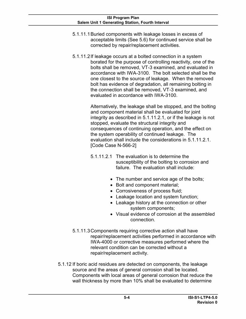
ISI Program Plan Salem Unit 1 Generating Station, Fourth Interval
5-4 ISI-S1-LTP4-5.0 Revision 0
5.1.11.1 Buried components with leakage losses in excess of acceptable limits (See 5.6) for continued service shall be corrected by repair/replacement activities.
5.1.11.2 If leakage occurs at a bolted connection in a system
borated for the purpose of controlling reactivity, one of the bolts shall be removed, VT-3 examined, and evaluated in accordance with IWA-3100. The bolt selected shall be the one closest to the source of leakage. When the removed bolt has evidence of degradation, all remaining bolting in the connection shall be removed, VT-3 examined, and evaluated in accordance with IWA-3100.
Alternatively, the leakage shall be stopped, and the bolting
and component material shall be evaluated for joint integrity as described in 5.1.11.2.1, or if the leakage is not stopped, evaluate the structural integrity and consequences of continuing operation, and the effect on the system operability of continued leakage. The evaluation shall include the considerations in 5.1.11.2.1. [Code Case N-566-2]
5.1.11.2.1 The evaluation is to determine the
susceptibility of the bolting to corrosion and failure. The evaluation shall include:
The number and service age of the bolts; Bolt and component material; Corrosiveness of process fluid; Leakage location and system function; Leakage history at the connection or other
system components; Visual evidence of corrosion at the assembled
connection.
5.1.11.3 Components requiring corrective action shall have repair/replacement activities performed in accordance with IWA-4000 or corrective measures performed where the relevant condition can be corrected without a repair/replacement activity.
5.1.12 If boric acid residues are detected on components, the leakage source and the areas of general corrosion shall be located. Components with local areas of general corrosion that reduce the wall thickness by more than 10% shall be evaluated to determine

ISI Program Plan Salem Unit 1 Generating Station, Fourth Interval
5-5 ISI-S1-LTP4-5.0 Revision 0
whether the component may be acceptable for continued service, or whether repair/replacement activities will be performed.
5.1.13 Records associated with pressure testing shall comply with IWA-
5300 and IWA-6000.
5.2 System Pressure Test Methods
5.2.1 The pressure testing method applicable to Class 1, 2 and 3 components are as specified in this section. Multiple tests and methods may be required to test the entire test boundary.
5.2.2 Pressure retaining components within each system boundary shall
be subject to the following applicable system pressure tests under which conditions a visual examination, VT-2 is to be performed to detect leakage. [IWA-5211]
5.2.2.1 A System Leakage Test conducted while the system is in
operation, during a system operability test, or while the system is at test conditions using an external pressurization source.
5.2.2.2 In lieu of a System Leakage Test and visual examination, a
System Hydrostatic Test and visual examination can be conducted as described in Paragraph 5.4.
5.2.2.3 In lieu of a System Leakage Test and visual examination, a
System Pneumatic Test and visual examination can be conducted for Class 2 or 3 components as permitted by Paragraph 5.5.
5.2.3 System Leakage and System Hydrostatic Tests are to be
conducted at the pressure and temperature specified in this SPT ISI Plan for the classification of piping or components being tested. The System Hydrostatic Test pressure shall not exceed the maximum allowable test pressure of any component within the system pressure test boundary.
5.2.4 Except as specified in Paragraph 5.5, the contained fluid in the
system during normal system operation shall be used as the pressurizing medium. [IWB-5210(b), IWC-5210(b), IWD-5210(b)]
(a) When the contained fluid in a Class 2 or 3 system is steam,
either water or gas can be used as the pressurizing medium.

ISI Program Plan Salem Unit 1 Generating Station, Fourth Interval
5-6 ISI-S1-LTP4-5.0 Revision 0
(b) When water is used as the pressurizing medium in systems which normally contain steam, travel stops or pins must be installed on spring hangers and constant supports.
5.2.5 When portions of systems are subject to system pressure tests
associated with two different system functions, the visual examination need only be performed during the test conducted at the higher of the test pressures of the respective system function except as permitted in paragraph 5.4.1.2.
5.2.6 The system test pressure and temperature may be obtained by
using any means that comply with the plant Technical Specifications, except that if the test boundary includes the reactor vessel, nuclear heat cannot be used for obtaining test conditions. [IWA-5212(g) and 10 CFR 50 Appendix G]
5.2.7 Holding times after pressurization to the minimum required test
conditions are defined in paragraphs 5.3.2.3, or 5.3.3.3. These holding times apply for Class 1 or Class 2 and 3 System Leakage Testing as well as for Hydrostatic or Pneumatic Testing performed in lieu of System Leakage Testing.
5.2.8 System test conditions are to be maintained essentially constant
(and above the minimum test pressure) during the duration of the pressure test visual examination, except as provided in paragraph 5.2.9. If pressure is not maintained above the minimum test pressure during performance of the pressure test visual examination, suspend the examination until system test conditions are restored. Once system test conditions are returned, the examination may continue (including the appropriate system hold time). [IWA-5212(c)]
5.2.9 Elevated Temperature Tests [IWA-5245]
The test pressure may be lowered for the conduct of the visual examination for Class 1, 2 and 3 systems that require a test temperature above 200°F during the system pressure test, after the required test hold time has been satisfied. The pressure may be lowered to a level corresponding with a temperature of 200°F, in accordance with allowable cooldown rates established by fracture prevention criteria.

ISI Program Plan Salem Unit 1 Generating Station, Fourth Interval
5-7 ISI-S1-LTP4-5.0 Revision 0
5.3 System Leakage Testing
5.3.1 System pressure shall be verified by normal system instrumentation, test instrumentation, or through performance of the system operating or surveillance procedure. [IWA-5212(b)]
5.3.2 Class 1 System Leakage Test [IWB-5220]
5.3.2.1 The system pressure testing of Class 1 components shall be conducted following each refueling outage prior to plant startup. [Table IWB-2500-1, Category B-P]
5.3.2.2 Test conditions:
(a) The Class 1 System Leakage Test shall be conducted at a pressure not less than the pressure corresponding to 100% rated reactor power, except as allowed by paragraph 5.3.2.2(e) for bolted connections. The minimum temperature for the system leakage testing is that temperature prescribed by the Technical Specifications (T/S), as modified by the results obtained from each set of material surveillance specimens withdrawn from the reactor vessel during service life.
(b) The system pressure and temperature shall be
attained at a rate in accordance with the heat-up limitations specified for the system.
(c) The minimum test temperature for the System
Leakage Test shall not be lower than the minimum temperature for the associated pressure specified in the plant Technical Specifications.
(d) For tests of systems or portions of systems
constructed entirely of austenitic steel, test temperature limitations are not required to meet fracture prevention criteria. In cases where the components of the system are constructed of ferritic and austenitic steels that are nonisolable from each other during a System Leakage Test, the test temperature shall be in accordance with paragraph 5.3.2.2(a).

ISI Program Plan Salem Unit 1 Generating Station, Fourth Interval
5-8 ISI-S1-LTP4-5.0 Revision 0
(e) Bolted connections in system borated for the purpose of controlling reactivity must meet the requirements of paragraph 5.1.8.
. 5.3.2.3 Test holding time:
(a) No holding time is required after attaining test pressure for System Leakage Tests.
5.3.2.4 Test pressurization boundary requirements:
(a) For the system pressure test performed each refueling outage, the pressurization boundary shall correspond to the reactor coolant boundary, with all valves in the position required for normal reactor operation startup.
(b) For the Class 1 System Leakage Test conducted at
or near the end of the inspection interval, the pressurization boundary shall extend to all Class 1 pressure retaining components within the system boundary.
5.3.2.5 Examination boundary requirements:
(a) The system pressure test visual examination boundary for the test pressurization boundary in 5.3.2.4(a) shall include all Class 1 pressure retaining components. See Technical Approach and Position SM1-I4T-01.
(b) The system pressure test visual examination boundary for the test pressurization boundary in 5.3.2.4(b) shall include all Class 1 pressure retaining components.
5.3.3 Class 2 and 3 System Leakage Test [IWC-5220, IWD-5220]
Note: 10CFR50.55a(b)(2)(xx) System leakage tests. When performing system leakage tests in accordance IWA-5213(a), 1997 Addenda through the latest edition and addenda incorporated by reference in paragraph (b)(2) of this section, a 10-minute hold time after attaining test pressure is required for Class 2 and Class 3 components that are not in use during normal operating conditions, and no hold time is required for the remaining Class 2 and Class 3 components provided that the system has been in operation for at least 4 hours for insulated components or 10 minutes for uninsulated components.
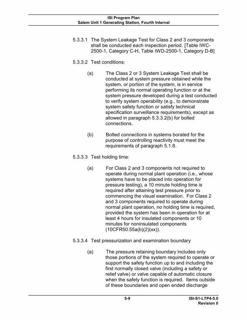
ISI Program Plan Salem Unit 1 Generating Station, Fourth Interval
5-9 ISI-S1-LTP4-5.0 Revision 0
5.3.3.1 The System Leakage Test for Class 2 and 3 components
shall be conducted each inspection period. [Table IWC-2500-1, Category C-H, Table IWD-2500-1, Category D-B]
5.3.3.2 Test conditions:
(a) The Class 2 or 3 System Leakage Test shall be conducted at system pressure obtained while the system, or portion of the system, is in service performing its normal operating function or at the system pressure developed during a test conducted to verify system operability (e.g., to demonstrate system safety function or satisfy technical specification surveillance requirements), except as allowed in paragraph 5.3.3.2(b) for bolted connections.
(b) Bolted connections in systems borated for the
purpose of controlling reactivity must meet the requirements of paragraph 5.1.8.
5.3.3.3 Test holding time:
(a) For Class 2 and 3 components not required to operate during normal plant operation (i.e., whose systems have to be placed into operation for pressure testing), a 10 minute holding time is required after attaining test pressure prior to commencing the visual examination. For Class 2 and 3 components required to operate during normal plant operation, no holding time is required, provided the system has been in operation for at least 4 hours for insulated components or 10 minutes for noninsulated components (10CFR50.55a(b)(2)(xx)).
5.3.3.4 Test pressurization and examination boundary
(a) The pressure retaining boundary includes only
those portions of the system required to operate or support the safety function up to and including the first normally closed valve (including a safety or relief valve) or valve capable of automatic closure when the safety function is required. Items outside of these boundaries and open ended discharge
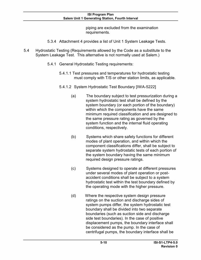
ISI Program Plan Salem Unit 1 Generating Station, Fourth Interval
5-10 ISI-S1-LTP4-5.0 Revision 0
piping are excluded from the examination requirements.
5.3.4 Attachment 4 provides a list of Unit 1 System Leakage Tests.
5.4 Hydrostatic Testing (Requirements allowed by the Code as a substitute to the
System Leakage Test. This alternative is not normally used at Salem.)
5.4.1 General Hydrostatic Testing requirements:
5.4.1.1 Test pressures and temperatures for hydrostatic testing must comply with T/S or other station limits, as applicable.
5.4.1.2 System Hydrostatic Test Boundary [IWA-5222]
(a) The boundary subject to test pressurization during a system hydrostatic test shall be defined by the system boundary (or each portion of the boundary) within which the components have the same minimum required classification and are designed to the same pressure rating as governed by the system function and the internal fluid operating conditions, respectively.
(b) Systems which share safety functions for different
modes of plant operation, and within which the component classifications differ, shall be subject to separate system hydrostatic tests of each portion of the system boundary having the same minimum required design pressure ratings.
(c) Systems designed to operate at different pressures
under several modes of plant operation or post-accident conditions shall be subject to a system hydrostatic test within the test boundary defined by the operating mode with the higher pressure.
(d) Where the respective system design pressure
ratings on the suction and discharge sides of system pumps differ, the system hydrostatic test boundary shall be divided into two separate boundaries (such as suction side and discharge side test boundaries). In the case of positive displacement pumps, the boundary interface shall be considered as the pump. In the case of centrifugal pumps, the boundary interface shall be

ISI Program Plan Salem Unit 1 Generating Station, Fourth Interval
5-11 ISI-S1-LTP4-5.0 Revision 0
the first shutoff valve on the discharge side of the pump.
5.4.1.3 Consider the following actions to protect permanent
system instrumentation when performing system hydrostatic tests:
(a) Determine whether instruments must be isolated at
the instrument shutoff valve, disconnected, or otherwise vented.
5.4.1.4 When performing system hydrostatic tests the following
precautions must be taken to protect plant components such as pumps, valves and heat exchangers:
(a) Where valves are used as test boundaries, pressure
shall not exceed the maximum hydrostatic seat pressure as determined from vendor data or Engineering.
(b) If motor or air operated valves or control valves are
used as test boundaries, care must be taken to preclude excessive differential pressure as determined from manufacturer's data or Engineering.
(c) The maximum allowable pressure or differential
pressure shall be verified from manufacturer's data or Engineering for pumps, valves, heat exchangers (shell to tube differential), and other in line equipment prior to testing.
(d) Relief and safety valves are to be removed and the
piping/component inlet flanges blanked off, or are to be gagged according to valve manufacturers or Engineering’s recommendations during pressure tests. In no case is it permissible to change the spring setting on relief or safety valves without prior concurrence from Engineering.
(e) Expansion joints shall be temporarily restrained,
isolated or otherwise protected unless they are rated for the test pressure.
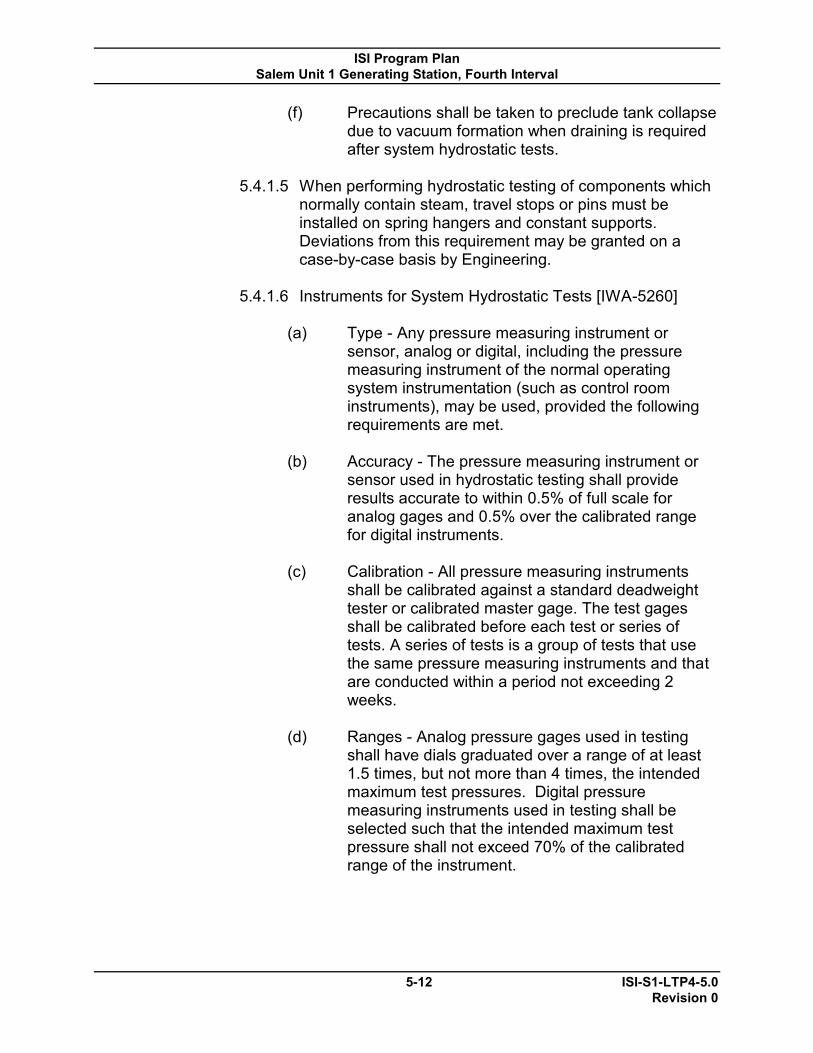
ISI Program Plan Salem Unit 1 Generating Station, Fourth Interval
5-12 ISI-S1-LTP4-5.0 Revision 0
(f) Precautions shall be taken to preclude tank collapse due to vacuum formation when draining is required after system hydrostatic tests.
5.4.1.5 When performing hydrostatic testing of components which
normally contain steam, travel stops or pins must be installed on spring hangers and constant supports. Deviations from this requirement may be granted on a case-by-case basis by Engineering.
5.4.1.6 Instruments for System Hydrostatic Tests [IWA-5260]
(a) Type - Any pressure measuring instrument or sensor, analog or digital, including the pressure measuring instrument of the normal operating system instrumentation (such as control room instruments), may be used, provided the following requirements are met.
(b) Accuracy - The pressure measuring instrument or
sensor used in hydrostatic testing shall provide results accurate to within 0.5% of full scale for analog gages and 0.5% over the calibrated range for digital instruments.
(c) Calibration - All pressure measuring instruments
shall be calibrated against a standard deadweight tester or calibrated master gage. The test gages shall be calibrated before each test or series of tests. A series of tests is a group of tests that use the same pressure measuring instruments and that are conducted within a period not exceeding 2 weeks.
(d) Ranges - Analog pressure gages used in testing
shall have dials graduated over a range of at least 1.5 times, but not more than 4 times, the intended maximum test pressures. Digital pressure measuring instruments used in testing shall be selected such that the intended maximum test pressure shall not exceed 70% of the calibrated range of the instrument.

ISI Program Plan Salem Unit 1 Generating Station, Fourth Interval
5-13 ISI-S1-LTP4-5.0 Revision 0
Note: It is not necessary to isolate components by altered valve lineups or other means solely to reduce the test boundary elevation difference and permit pressurizing the entire test boundary to the minimum test pressure. Likewise, it is not acceptable to extend the system test boundary to reduce the required system hydrostatic pressure.
(e) Location – When testing an isolated component, the pressure measuring instrument or sensor shall be connected close to the component. When testing a group of components or a multi-component system, the pressure measuring instrument or sensor shall be connected to any point within the pressure boundary of the components or system such that the imposed pressure on any component, including static head, will not exceed 106% of the specified test pressure for the system; even though the specified test pressure may not be achieved at the highest elevations in the system.
5.4.2 Class 1 System Hydrostatic Test [IWB-5230]
The Class 1 System Hydrostatic Test may be conducted at any test pressure specified in Table 5-1, corresponding to the selected test temperature, provided the requirements of 5.4.2.1 through 5.4.2.3 are met for all ferritic steel components within the boundary of the system (or portion of system) subject to the test pressure.
5.4.2.1 Whenever a hydrostatic test is conducted in which the
reactor vessel contains nuclear fuel and the vessel is within the system test boundary, the test pressure shall not exceed the limiting conditions specified in the plant Technical Specifications.
5.4.2.2 The minimum test temperature for the System Hydrostatic
Test shall not be lower than the minimum temperature for the associated pressure specified in the plant Technical Specifications.
5.4.2.3 The System Hydrostatic Test temperature shall be
modified as required by the results obtained from each set of material surveillance specimens withdrawn from the reactor vessel during the service lifetime.

ISI Program Plan Salem Unit 1 Generating Station, Fourth Interval
5-14 ISI-S1-LTP4-5.0 Revision 0
TABLE 5-1 TEST PRESSURE Test Temperature, °F Test Pressure, psig 1,2
100 or less 1.10 Po 200 1.08 Po 300 1.06 Po 400 1.04 Po
500 or greater 1.02 Po NOTES: (1) Po is the nominal operating pressure corresponding to 100% rated reactor power. (2) Linear interpolation at intermediate test temperatures is permissible.
5.4.3 Class 2 and Class 3 System Hydrostatic Test [IWC-5230, IWD-5230] 5.4.3.1 The Class 2 and Class 3 System Hydrostatic test pressure
shall be at least 1.10 times the system pressure Psv for systems with Design Temperature of 200°F or less, and at least 1.25 times the system pressure Psv for systems with Design Temperature above 200°F. The system pressure Psv shall be the lowest pressure setting among the number of safety or relief valves provided for overpressure protection within the boundary of the system to be tested. For systems (or portions of systems) not provided with safety or relief valves, the system design pressure Pd shall be substituted for Psv.
5.4.3.2 In the case of atmospheric storage tanks, the nominal
hydrostatic pressure, developed with the tank filled to its design capacity, shall be acceptable as the system test pressure.
5.4.3.3 For 0–15 psig storage tanks, the test pressure shall be 1.1
PG, Design Pressure of vapor or gas space above liquid level for which overpressure protection is provided by relief valves.
5.4.3.4 For the purpose of the test, open ended portions of a
suction or drain line from a storage tank extending to the first shutoff valve shall be considered as an extension of the storage tank.
5.4.3.5 For open ended portions of discharge lines beyond the last
shutoff valve in non-closed Class 2 systems (e.g., containment spray header), demonstration of an open flow

ISI Program Plan Salem Unit 1 Generating Station, Fourth Interval
5-15 ISI-S1-LTP4-5.0 Revision 0
path test shall be performed in lieu of the system hydrostatic test. Test personnel need not be qualified for visual examination, VT-2.
5.4.3.6 For open ended portions of discharge lines beyond the last
shutoff valve in non-closed Class 3 systems (e.g., service water systems), confirmation of adequate flow during system operation shall be acceptable in lieu of system hydrostatic test. Test personnel need not be qualified for visual examination, VT-2.
5.4.3.7 Open ended vent and drain lines extending beyond the last
shutoff valve and open ended safety or relief valve discharge lines are exempt from hydrostatic testing.
5.4.3.8 Temperature [IWC-5240, IWD-5240] (a) The system test temperature during a system hydrostatic
test in systems containing ferritic steel components shall meet the requirements specified by fracture prevention criteria.
Note: Pneumatic Testing is potentially dangerous. If a leak develops, rapid expansion of compressed gas could occur. This test method should only be used when absolutely necessary.
5.5 Pneumatic Testing (Currently Pneumatic testing is not used at Salem; it may be
used as an alternative at a future date.)
5.5.1 The test pressure for a pneumatic test shall be the pressure required for the Class 2 or Class 3 System Leakage test in paragraph 5.3.3 or the Class 2 or Class 3 System Hydrostatic Test per paragraph 5.4.3.
5.5.2 The system pneumatic test may be used for system leakage test or
system hydrostatic test of Class 2 and 3 components whose contained fluid is a gas. The pneumatic test may also be used in lieu of system leakage or system hydrostatic testing when the system contained fluid is steam.
5.5.3 The test medium used shall be the contained fluid in the system
except as indicated previously for steam systems, which may use either water or a gas.
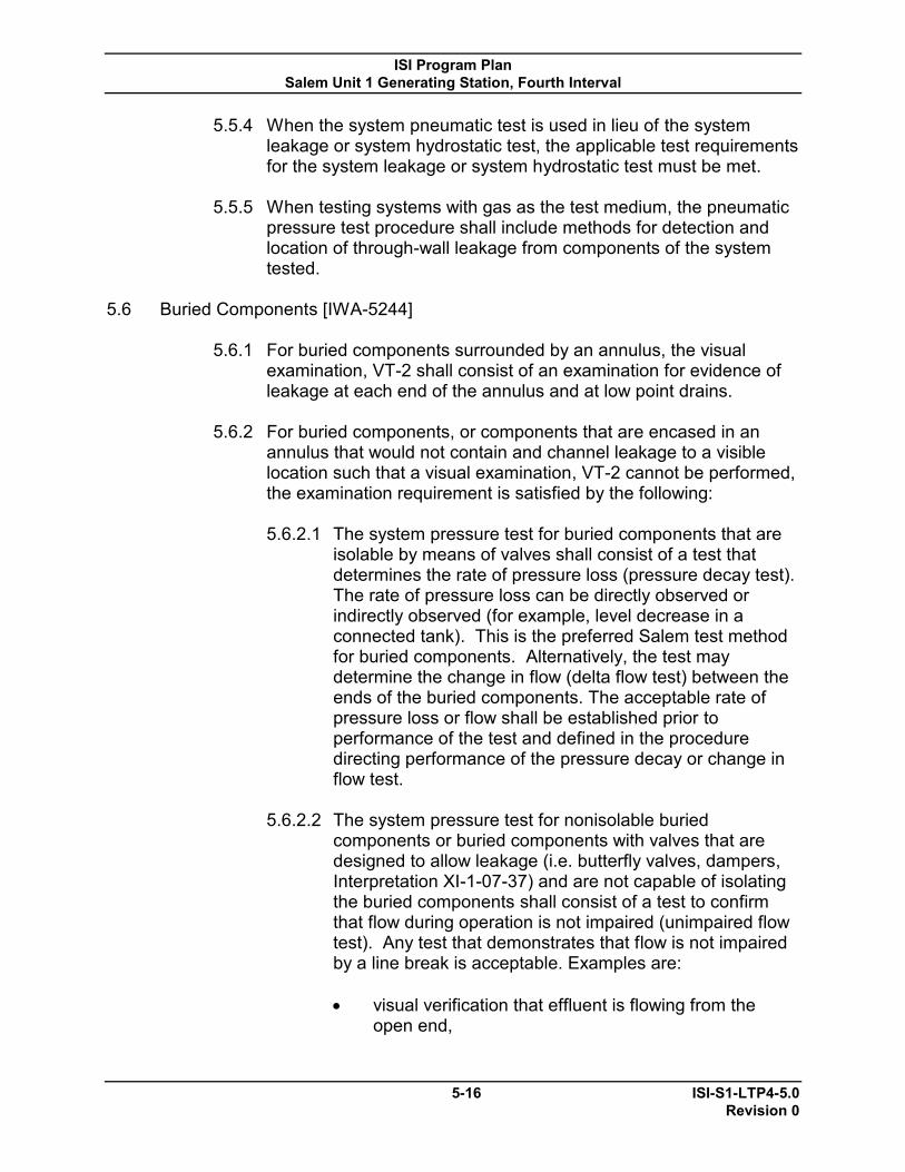
ISI Program Plan Salem Unit 1 Generating Station, Fourth Interval
5-16 ISI-S1-LTP4-5.0 Revision 0
5.5.4 When the system pneumatic test is used in lieu of the system leakage or system hydrostatic test, the applicable test requirements for the system leakage or system hydrostatic test must be met.
5.5.5 When testing systems with gas as the test medium, the pneumatic
pressure test procedure shall include methods for detection and location of through-wall leakage from components of the system tested.
5.6 Buried Components [IWA-5244]
5.6.1 For buried components surrounded by an annulus, the visual
examination, VT-2 shall consist of an examination for evidence of leakage at each end of the annulus and at low point drains.
5.6.2 For buried components, or components that are encased in an
annulus that would not contain and channel leakage to a visible location such that a visual examination, VT-2 cannot be performed, the examination requirement is satisfied by the following:
5.6.2.1 The system pressure test for buried components that are
isolable by means of valves shall consist of a test that determines the rate of pressure loss (pressure decay test). The rate of pressure loss can be directly observed or indirectly observed (for example, level decrease in a connected tank). This is the preferred Salem test method for buried components. Alternatively, the test may determine the change in flow (delta flow test) between the ends of the buried components. The acceptable rate of pressure loss or flow shall be established prior to performance of the test and defined in the procedure directing performance of the pressure decay or change in flow test.
5.6.2.2 The system pressure test for nonisolable buried
components or buried components with valves that are designed to allow leakage (i.e. butterfly valves, dampers, Interpretation XI-1-07-37) and are not capable of isolating the buried components shall consist of a test to confirm that flow during operation is not impaired (unimpaired flow test). Any test that demonstrates that flow is not impaired by a line break is acceptable. Examples are:
visual verification that effluent is flowing from the
open end,

ISI Program Plan Salem Unit 1 Generating Station, Fourth Interval
5-17 ISI-S1-LTP4-5.0 Revision 0
acceptable pump differential pressure at referenced flow,
visual verification of flow into drains or ducts, verification of changing basin, tank or vessel levels, verification of flow by instrumentation
5.6.2.3 Because neither the pressure decay test, the delta flow test, nor the unimpaired flow test involves performance of a visual examination, test personnel need not be qualified for visual examination, VT-2.
5.6.2.4 Salem relief request S1-I4R-102 (pending, use restricted
until SER received with approval) proposed for buried portions of the Class 3, 11 & 12 Nuclear Service Water (SW) Supply Headers the following alternative:
1) A visual examination of the ground surface areas
(includes surfaces of asphalt or other pavement materials) above all SW piping buried in soil shall be performed during all current and subsequent inspection outages to detect evidence of through-wall leakage in the buried components. The system shall have been in operation at nominal operating conditions for at least 24 hours prior to performing the visual examinations, in lieu of performing the periodic test required by IWA-5244(b)(1). The ASME Section XI code only requires a pressure test once each period. Since the SW system is in-service for extended periods of time, any leakage would be readily identified by plant personnel performing routine inspections during rounds.
2) Visual examination of the inside surface of all SW
buried piping are performed on a two refueling outage frequency to ensure that piping is unobstructed and any evidence of piping degradation is identified and is evaluated or repaired.
5.6.3 Specific locations of buried components and method of testing are
identified in the test procedures and implementation schedule. 5.6.4 Attachment 2 contains a listing of Salem Unit 1 drawings which
have buried components.
5.7 Special Test Methods [IWA-2240]

ISI Program Plan Salem Unit 1 Generating Station, Fourth Interval
5-18 ISI-S1-LTP4-5.0 Revision 0
Note: 10CFR50.55a(b)(2)(xix) Substitution of alternative methods. The provisions for the substitution of alternative examination methods, a combination of methods, or newly developed techniques in the 1997 Addenda of IWA-2240 must be applied. The provisions in IWA-2240, 1998 Edition through the latest edition and addenda incorporated by reference in paragraph (b)(2) of this section, are not approved for use. The provisions in IWA-4520(c), 1997 Addenda through the latest edition and addenda incorporated by reference in paragraph (b)(2) of this section, allowing the substitution of alternative examination methods, a combination of methods, or newly developed techniques for the methods specified in the Construction Code are not approved for use.
Special test or examination methods are permitted as alternates to the required system pressure test or examination method in Section XI. Where an alternate method is used in lieu of the specified method, the applicable requirements of this Program shall be followed and the alternate shall be acceptable to the ANII as being equivalent or superior to the specified method.
5.8 Augmented Programs 5.8.1 Certain augmented programs will utilize the ASME Section XI System Pressure
Test Program in whole or part to fulfill requirements of the augmented program. The specific requirements are detailed in the augmented program procedures. Descriptions of the Salem Unit 1 Augmented Examination Requirements are provided in Section 2.2 of the ISI Plan. More detailed requirements associated with the NUREG-0578 augmented program are provided in Attachment 3 of this section.
5.9 Definitions 5.9.1 Annulus
Reference to an annulus occurs in the buried piping requirements. An annulus refers to guard pipe or other material surrounding components, which would allow detection of leakage by observing for evidence of leakage at each end of the annulus and at low point drains. (IWA- 5244)
5.9.2 Buried Components
Components that are in direct contact with soil or concrete. (IWA-5244, see NUREG 1801, Rev 2, GALL Report, page 549)
5.9.3 Change-In-Flow Test
Test performed for buried piping requiring the measurement of flow on each end of the buried piping and the resultant change. The test acceptance criteria shall

ISI Program Plan Salem Unit 1 Generating Station, Fourth Interval
5-19 ISI-S1-LTP4-5.0 Revision 0
be established in the test procedure by engineering. A visual examination, VT-2 is not required. (IWA-5244)
5.9.4 Code Case
As used in this Program, approved ASME Section XI Code Cases that are documented in the ISI Plan. (IWA-2420)
5.9.5 Confirmation of Adequate Flow Test
Test substituted for a Class 3 hydrostatic test on open ended portions of discharge lines beyond the last shutoff valve in nonclosed systems (e.g., service water system). The test acceptance criteria shall be established in the test procedure, by engineering. Test personnel need not be qualified for visual examination, VT-2. (IWD-5230)
5.9.6 Corrective Action
Action taken to resolve flaws and relevant conditions, including supplemental examinations, analytical evaluations, repair/replacement activities, and corrective measures (IWA-9000)
5.9.7 Corrective Measures
Actions (such as maintenance) taken to resolve relevant conditions, but not including supplemental examinations, analytical evaluations, and repair/replacement activities (IWA-9000)
5.9.8 Demonstration of Open Flow Path Test
Test substituted for a Class 2 hydrostatic test on open ended portions of discharge lines beyond the last shutoff valve in nonclosed systems (e.g., containment spray header). The test acceptance criteria shall be established in the test procedure, by engineering. Test personnel need not be qualified for visual examination, VT-2. (IWC-5230)
5.9.9 Flow Not Impaired Test
Test performed for buried piping when isolable valves do not exist. The test acceptance criteria shall be established in the test procedure, by engineering. A visual examination, VT-2 is not required. (IWA-5244, see 5.6.2.2)
5.9.10 Hold Time
The hold time after pressurization to test conditions, before the visual examination commences as identified in the test procedure. The hold time as

ISI Program Plan Salem Unit 1 Generating Station, Fourth Interval
5-20 ISI-S1-LTP4-5.0 Revision 0
applicable is described in the test procedure and is based upon the applicable ASME Section XI Code, which may be modified depending on test location or test type by NRC limitations in 10 CFR 50.55a(b)(2) and approved requests for alternative. (IWA-5213)
5.9.11 Inaccessible Components
Components whose external surfaces cannot be examined using the direct visual examination, VT-2 method. Alternative requirements are provided in IWA-5241.
5.9.12 Insulated Components
Components whose external surfaces are covered by insulation or other wrapping (e.g., heat tracing) preventing direct observation of the component surface. (IWA-5242)
5.9.13 Isolable Valves
Valves that form a boundary to support testing of buried components. (IWA-5244)
5.9.14 Pressure Drop Test
Test performed for buried piping by means of isolable valves and external pressure source. The test acceptance criteria shall be established in the test procedure, based upon good engineering judgment. Monitoring level change in tanks, when the pressure is only static head, is an acceptable method. A visual examination, VT-2 is not required. (IWA-5244)
5.9.15 Relevant Condition
A condition observed during a visual examination that requires supplemental examination, corrective measure, correction by repair/replacement activities, or analytical evaluation. (IWA-9000)
The following relevant conditions that may be detected during the conduct of system pressure tests shall require corrective action or corrective measures prior to continued service, as appropriate:
a. Leakage (that is through-wall or through weld leakage that penetrates the
pressure retaining membrane) from insulated and noninsulated components;
b. Leakage in excess of limits established by engineering from mechanical connections (such as pipe caps, bolted connections, or compression

ISI Program Plan Salem Unit 1 Generating Station, Fourth Interval
5-21 ISI-S1-LTP4-5.0 Revision 0
fittings) or from components provided with leakage limiting devices (such as valve packing glands or pump seals).;
. c. Areas of general corrosion of a component resulting from leakage; d. Discoloration or accumulated residues on surfaces of components,
insulation, or floor areas that may be evidence of borated water leakage or;
e. Leakages or flow test results from buried components in excess of limits established by the test procedure as unacceptable.
5.9.16 Start-Up
A time requirement established for Class 1 system leakage pressure testing is prior to start-up. In this context prior to start-up is following a refueling outage, or maintenance outage in a repair scenario, but prior to plant start-up. Salem has identified this time period as prior to Mode 3. (Table IWB-2500-1, Cat. B-P, Note 2)
5.9.17 Structural Distress
The test record discusses evidence of structural distress with regard to itemization in the test record. The code provides no other information as to this requirement. Salem's position is that structural problems that may be observed while performing a system pressure test such as, evidence of water hammer or other similar nonconforming condition shall be recorded in the test record and reported in the corrective action program. The scope of the visual examination, VT-2 remains focused on conditions that show evidence of leakage. (IWA-5300)
5.9.18 Systems Borated for the Purpose of Controlling Reactivity
Systems identified in Attachment 1, which require identification of applicable bolting requiring insulation removal during the test procedure or by separate visual examination, VT-2 when the system is depressurized. (IWA-5242)
5.9.19 System Hydrostatic Test
A test conducted during a plant shutdown at an elevated test pressure as specified by the ASME Section XI Code. A visual examination, VT-2 is required. (IWA-5211)
5.9.20 System Leakage Test
A test conducted while the system is in operation, during a system operability test, or while the system is at test conditions using an external pressurization source. A visual examination, VT-2 is required. (IWA-5211)
5.9.21 System Pneumatic Test

ISI Program Plan Salem Unit 1 Generating Station, Fourth Interval
5-22 ISI-S1-LTP4-5.0 Revision 0
A test conducted in lieu of a system leakage or hydrostatic test for Class 2 and 3 components as permitted by the ASME Section XI Code. The requirements for system leakage and hydrostatic tests are applicable to pneumatic tests. A visual examination, VT-2 is required. (IWA-5211)
5.9.22 Test and Examination Boundary
The boundary subject to test pressurization is identified in the test procedure and supporting test boundary drawings. The VT-2 examination boundary will include the pressurized areas, and in certain instances connecting non-pressurized portions of systems (e.g., non-end of interval Class 1 System Leakage Test)
5.9.23 Test Pressure
Pressure described in the test procedure. The system test pressure may be obtained by any means that complies with the plant Technical Specifications, except if the test boundary includes the reactor vessel, nuclear heat cannot be used for obtaining test conditions. (IWA-5212 and 10 CFR 50 Appendix G)
5.9.24 Test Procedure
The procedure that provides the applicable test requirements of ASME Section XI for system pressure testing. (IWA-5300)
5.9.25 Test Record
A record of the visual examination conducted during a system pressure test including the test procedure documenting the test condition and pressure test boundary. Any source of leakage or evidence of structural distress shall be itemized, and the location and corrective action documented. Typically the information is recorded on the appropriate visual examination, VT-2 form in combination with the test procedure. (IWA-5300)
5.9.26 Test Temperature
Temperature described in the test procedure. The system test temperature may be obtained by any means that comply with the plant Technical Specifications, except if the test boundary includes the reactor vessel, nuclear heat cannot be used for obtaining test conditions. (IWA-5212 and 10 CFR 50 Appendix G)
5.9.27 Visual Examination, VT-2
Visual examinations, VT-2 are conducted to detect evidence of leakage from pressure retaining components, with or without leakage collection systems, as required during the conduct of system pressure test.

ISI Program Plan Salem Unit 1 Generating Station, Fourth Interval
5-23 ISI-S1-LTP4-5.0 Revision 0
Attachment 1
Listing of Systems Borated for the Purpose of Controlling Reactivity Section 5.1.8 addresses bolting examination during system pressure testing in systems borated for the purpose of controlling reactivity, when the component is insulated. The following systems are borated for the purpose of controlling reactivity: Reactor Coolant Chemical Volume and Control Safety Injection Residual Heat Removal Spent Fuel Cooling Containment Spray
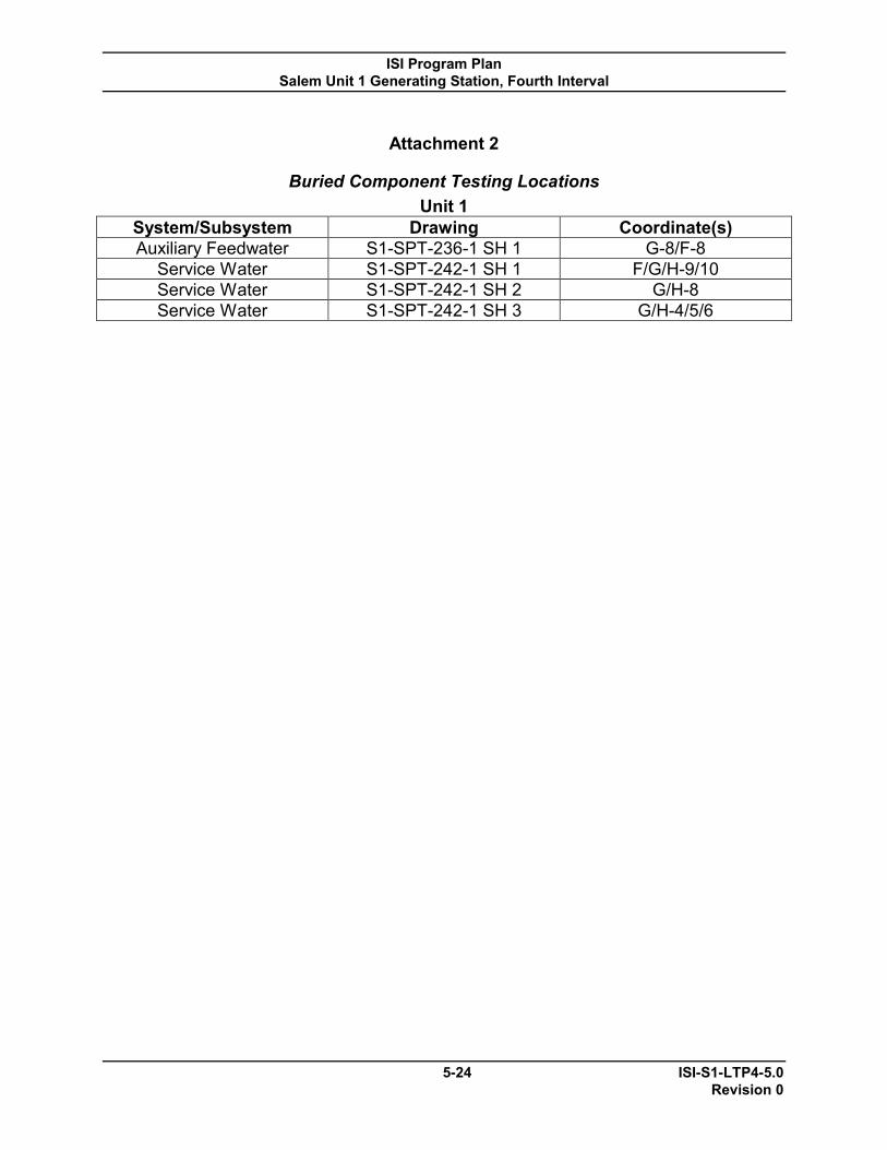
ISI Program Plan Salem Unit 1 Generating Station, Fourth Interval
5-24 ISI-S1-LTP4-5.0 Revision 0
Attachment 2
Buried Component Testing Locations Unit 1
System/Subsystem Drawing Coordinate(s) Auxiliary Feedwater S1-SPT-236-1 SH 1 G-8/F-8
Service Water S1-SPT-242-1 SH 1 F/G/H-9/10 Service Water S1-SPT-242-1 SH 2 G/H-8 Service Water S1-SPT-242-1 SH 3 G/H-4/5/6

ISI Program Plan Salem Unit 1 Generating Station, Fourth Interval
5-25 ISI-S1-LTP4-5.0 Revision 0
Attachment 3
NUREG-0578
ECCS Leakage Monitoring and Reduction Program Overview The ECCS Leakage Monitoring and Reduction Program covers the portions of the systems listed below that are located outside of the primary containment that could be subject to highly radioactive fluids during the recirculation phase of an accident. The scope does not include the containment isolation valves that are tested for leakage in accordance with 10 CFR 50 Appendix J. For those valves where the packing is not exposed to test pressure during 10 CFR 50, Appendix J testing, the valve packing shall be included in the ECCS leakage Monitoring and Reduction Program. The systems included in the program are:
RHR from RH4s to the Containment Containment Spray from CS2s to the Containment High Head Safety Injection from SJ1 and SJ2 to the Containment Intermediate Head Safety Injection – Cold Leg and Hot Leg from SJ30 to the
Containment CVCS – Charging and Seal Injection and Seal Return Liquid Waste Gaseous Waste PASS
The objective of the program is to detect and correct any degradation of the pressure boundaries of the above systems and thereby reduce post-accident dose rates and airborne activity in the Auxiliary building in accordance with Technical Specification 6.8.4.a. This would also have the effect of reducing the amount of radioactivity released to the atmosphere through the Auxiliary Building Ventilation System following an accident. The program makes use of multiple elements to control leakage:
Design features to minimize leakage Instrumentation to detect gross leakage (e.g., area radiation monitors and sump
level alarms) Visual examination during system operation Periodic leakage tests Implementation of a vigorous corrective action program to correct leakage
problems once they have been identified Preventive Maintenance Activities

ISI Program Plan Salem Unit 1 Generating Station, Fourth Interval
5-26 ISI-S1-LTP4-5.0 Revision 0
These various elements of the process to control leakage have been built into the procedures and programs at Salem in accordance with the Salem Quality Assurance Program. Periodic Leakage Tests Periodic leakage tests for the ECCS Leakage Monitoring and Reduction Program shall meet all the requirements of the Service Pressure Leak Tests of Salem Technical Specification 6.8.4.a(ii). Dual credit for ASME Section XI requirements may be taken if the test additionally meets the System Leakage Test criteria found in Section 5.3 of this document and the visual examination, VT-2 requirements. As a minimum periodic leakage tests for the program must be conducted on an every refueling outage cycle. The test area shall be pressurized with liquid systems operating at greater than minimum baseline discharge pressure (refer to associated pump baseline data sheets), and gaseous systems using an approved Type C leak test procedure, or equivalent. Table 5.1 provides a listing of Salem test procedures associated with the program, and Table 5.2 provides a listing of drawings identifying the test boundaries associated with the program. The appropriate acceptance criteria are documented in the test procedures.
Note: Exceeding 2300 cc/min total leakage limit may result in exceeding GDC-19 limits for Control Room habitability. Prompt action should be taken to reduce total leakage to less than 2300 cc/min.

ISI Program Plan Salem Unit 1 Generating Station, Fourth Interval
5-27 ISI-S1-LTP4-5.0 Revision 0
Table 5.1 ECCS Leakage Monitoring and Reduction Program Test Procedures
System/Subsystem Test Freq Responsible Organization
Procedure P&ID
11Cont. Spray Loop* Refueling Engineering S1.OP-ST.CS-0005(Q) / OU-AA-335-015
205235
12 Cont. Spray Loop*
Refueling Engineering S1.OP-ST.CS-0005(Q) / OU-AA-335-015
205235
11RHR Loop* Refueling Engineering S1.OP-ST.RHR-0005(Q) / OU-AA-335-015
205232
12 RHR Loop* Refueling Engineering S1.OP-ST.RHR-0005(Q) / OU-AA-335-015
205232
High Head Safety Injection*
Refueling Engineering S1.OP-ST.SJ-0016(Q) / OU-AA-335-015
205234
Intermediate Head Safety Injection – Cold Leg*
Refueling Engineering S1.OP-ST.SJ-0014(Q) / OU-AA-335-015
205234
Intermediate Head Safety Injection – Hot Leg*
Refueling Engineering S1.OP-ST.SJ-0015(Q) / OU-AA-335-015
205234
CVCS Charging* Refueling Engineering S1.OP-ST.CVC-0003(4)(5)(Q) / OU-AA-335-015(Q)
205228
CVCS Seal Injection / Seal Return*
Refueling Engineering S1.OP-ST.CVC-0003(4)(5)(Q) / OU-AA-335-015(Q)
205228
Waste Gas Refueling Engineering SC.SS-IS.WG-0003(Q) / OU-AA-335-015
205240
Waste Gas Refueling Operations S1.OP-LR.WG-0001(Q)
205240
Waste liquid Refueling Engineering S1.OP-SO.WL-0004(Q) / OU-AA-335-015
205239
PASS Refueling Engineering SC.CH-TI.PAS-1070(Q) / OU-AA-335-015
205244
ISI Program Plan Salem Unit 1 Generating Station, Fourth Interval
5-28 ISI-S1-LTP4-5.0 Revision 0
* - Any leaks observed during quarterly IST runs will be quantified and documented in the comments section of the associated procedure.

ISI Program Plan Salem Unit 1 Generating Station, Fourth Interval
5-29 ISI-S1-LTP4-5.0 Revision 0
Table 5.2
ECCS Leakage Monitoring and Reduction Program Test Boundaries Unit 1
SYSTEM/SUBSYSTEM DRAWING
Chemical and Volume Control Operation 669228 A 1352-1 SH 1 Chemical and Volume Control Operation 669228 A 1352-1 SH 2 Boric Acid Recovery 669229 A 1352-1 SH 2 Residual Heat Removal 669232 A 1352-1 SH 1 Residual Heat Removal 669232 A 1352-1 SH 2 Safety Injection 669234 A 1352-1 SH 1 Safety Injection 669234 A 1352-1 SH 2 Safety Injection 669234 A 1352-1 SH 3 Containment Spray 669235 A 1352-1 SH 1 Waste Disposal Liquid 669239 A 1352-1 SH 1 Waste Disposal Liquid 669239 A 1352-1 SH 2 Waste Disposal Liquid 669239 A 1352-1 SH 3 Waste Disposal Gas 669240 A 1352-1 SH 2 Sampling 669244 A 1352-1 SH 1 Sampling 669244 A 1352-1 SH 3

ISI Program Plan Salem Unit 1 Generating Station, Fourth Interval
5-30 ISI-S1-LTP4-5.0 Revision 0
Attachment 4
Unit 1 System Pressure Tests Listing Sum# Component
ID Instructions Drawing
950000 SPT-1-RC-001 CLASS 1 SYSTEMS
S1-ISI-201-2 & 3, S!-SPT-201-1
950050 SPT-1-AF-001
#11 AFW PUMP AND PIPING BOUNDED BY 11AF3. 12AF923, 13 & 14AF921 & 11AF101 RECIRC. RETURN TO THE AFST. S1-SPT-236
950100 SPT-1-AF-002
#12 AFW PUMP AND PIPING BOUNDED BY 12AF3. 11 & 12AF23. S1-SPT-236
950150 SPT-1-AF-003
BOUNDED BY 13 AFW PUMP BOUNDED BY 13AF3 S1-SPT-236
950200 SPT-1-AF-004 BOUNDED BY 11 & 12AF3, 13AF3 & AFWST S1-SPT-236
950210 SPT-1-AF-005
Drop Test - #14 AFW BURIED PIPING BOUNDED BY 14AF21&23 S1-SPT-236
950220 SPT-1-AF-006
Drop Test - #12 AFW BURIED PIPING BOUNDED BY 12AF21&23 S1-SPT-236
950225 SPT-1-BF-001 FEED WATER FOR 11 S/G, 11BF22 to 11 SG
S1-SPT-202 SH.3
950230 SPT-1-BF-002 FEED WATER FOR 12 S/G, 12BF22 to 12 SG
S1-SPT-202 SH.3
950235 SPT-1-BF-003 FEED WATER FOR 13 S/G, 13BF22 to 13 SG
S1-SPT-202 SH.3
950240 SPT-1-BF-004 FEED WATER FOR 14 S/G, 14BF22 to 14 SG
S1-SPT-202 SH.3
950300 SPT-1-CC-001
BOUNDED BY 1CC73, 1CC79 & #1 SEALWATER HX.
S1-SPT-231 SH2
950350 SPT-1-CC-002 BOUNDED BY 11CC6, 11CC8 & #11 CCWHX.
S1-SPT-231 SH1
950400 SPT-1-CC-003 BOUNDED BY 12CC377 & 12CC378 & 379
S1-SPT-231 SH1
950450 SPT-1-CC-004
BOUNDED BY SPENT FUEL HX, MS RAD MONITORS...10 YEAR 2 VALVES OPEN. POST LOCA SAMPLE COOLERS, BAE & WASTE GAS COMPRESSORS.
S1-SPT-231 SH2, SH1
950500 SPT-1-CC-005
BOUNDED BY 1CC911 & 1CC313 INSIDE OF CONTAINMENT 10 YEAR 2 VALVES OPEN.
S1-SPT-231 SH2, SH3
950550 SPT-1-CH-001
BOUNDED BY #1 CONTROL RM A/C UNIT, #1 EXPANSION TANK & 11 - 13 CHILLER UNITS.
S1-SPT-216 SH1,SH2,SH3
950600 SPT-1-CH-002
BOUNDED BY #1 ECAC & MS RAD MONITORS FOR THE S/G PERFORMED IN MODE 1 FOR
S1-SPT-216 SH3

ISI Program Plan Salem Unit 1 Generating Station, Fourth Interval
5-31 ISI-S1-LTP4-5.0 Revision 0
Attachment 4 Unit 1 System Pressure Tests Listing
Sum# Component ID
Instructions Drawing
RAD MONITORS AND ANY MODE FOR ECAC.
950650 SPT-1-CS-001
BOUNDED BY 1CS16, 1CS17 & SPRAY ADDITIVE TANK S1-SPT-235
950700 SPT-1-CS-002
BOUNDED BY DISCH OF 11 & 12 CS PMPS TO 11 & 12CS2, EDUCTOR AND RECIR. LINE. FULL FLOW OR 405P TESTING. S1-SPT-235
950750 SPT-1-CS-003
BOUNDED BY 11 & 12CS2 THRU THE TEMP. PIPING DURING THE CONTAINMENT SPRAY FULL FLOW TEST. S1-SPT-235
950800 SPT-1-CS-004
BOUNDED BY 1CS900, 1CS901, 1CS902 & 1CS903 PERFORM THIS SPT DURING THE LLRT. S1-SPT-235
950850 SPT-1-CV-001
BORIC ACID RECIRC. (100' & 120'), VCT ROOM CHARGING PUMP AREA, BORIC ACID STORAGE TANK AREA (20' AUX).
S1-SPT-228 SH1, SH2
950900 SPT-1-CV-002 CVC PIPING
S1-SPT-228 SH2, SH3
950950 SPT-1-CV-003
BOUNDED BY 1CV64, 1CV53, 1CV82, 1CV48 AND 11 THRU 14CV99.
S1-SPT-228 SH2, SH3
951000 SPT-1-CV-004 #11 CENTRIFUGAL CHARGING PUMP
S1-SPT-228 SH2
951050 SPT-1-CV-005 #12 CENTRIFUGAL CHARGING PUMP
S1-SPT-228 SH2
951100 SPT-1-CV-006
#13 CENTRIFUGAL CHARGING PUMP THIS EXAM IS FOR THE #13 CHRG PUMP WHICH IS ABANDONED IN PLACE AND PERMANENTLY TAGGED OUT AND ALSO CONSIDERED ABANDONED IN PLACE. DO NOT DELETE FROM LTP UNTIL DESIGN REVISED TO CUT & CAP.
S1-SPT-228 SH2, S1-SPT-234 SH1
951250 SPT-1-GB-001
BOUNDED BY 11-14 S/G BLOWDOWN LINES TO 11-14GB4
S1-SPT-225 SH1,SH2
951300 SPT-1-MS-001 #11-14 S/G MAIN STEAM PIPING
S1-SPT-203 SH1,SH2,SH6
951350 SPT-1-MS-002 BOUNDED BY 1MS201 & 13MS45
S1-SPT-203 SH1
951550 SPT-1-RH-001
BOUNDED BY SUCTION FROM #11 HOT LEG THRU #11 RHR LOOP TO 13RH27.
S1-SPT-232 SH1,SH2
951600 SPT-1-RH-002
BOUNDED BY 12RH4 THRU 12 RHR PUMP LOOP TO HOT LEGS THRU 1RH26.
S1-SPT-232 SH2

ISI Program Plan Salem Unit 1 Generating Station, Fourth Interval
5-32 ISI-S1-LTP4-5.0 Revision 0
Attachment 4 Unit 1 System Pressure Tests Listing
Sum# Component ID
Instructions Drawing
951750 SPT-1-SF-001
INSPECTION BOUNDARY SHOWN ON DRWG 603233-01 S1-SPT-233
951800 SPT-1-SJ-001
BOUNDED BY THE RWST & PUMP SUCTION PIPING
S1-SPT-234 SH1, SH2, SH3
951850 SPT-1-SJ-002 BOUNDED BY 11-14 ACCUMULATOR & 1SJ60
S1-SPT-234 SH4
951900 SPT-1-SJ-003
BOUNDED BY 11 & 12 SJ44 TO SUCTION OF RHR PUMPS
S1-SPT-234 SH3
951950 SPT-1-SJ-004
BOUNDED BY 11 SI PUMP SUCT. & DISCH VALVES 11SJ40, 11SJ134 & 12SJ33.
S1-SPT-234 SH1, SH2, SH4
952000 SPT-1-SJ-005
BOUNDED BY #12 SI PUMP SUCT. & DISCH VALVES 12SJ40, 12SJ134 & 12SJ33.
S1-SPT-234 SH2
952050 SPT-1-SJ-006 BOUNDED BY 11SJ40 TO THE HOT LEG
S1-SPT-234 SH1, SH2, SH3, SH4
952100 SPT-1-SJ-007 BOUNDED BY 12SJ40 TO THE HOT LEG
S1-SPT-234 SH2, SH3, SH4
952150 SPT-1-SJ-008 BOUNDED BY 11 & 12SJ134 TO THE COLD LEG
S1-SPT-234 SH2, SH3, SH4
952200 SPT-1-SJ-009 FROM C/SI PMPS THRU BIT TO COLD LEGS
S1-SPT-234 SH1, SH4
953050 SPT-1-SW-001
BOUNDED BY S.W. INTAKE DISCH. HDRS BAYS 1 & 2
S1-SPT-242 SH1, SH2
953100 SPT-1-SW-002 BOUNDED BY #13 S.W. PUMP & STRAINER
S1-SPT-242 SH1
953150 SPT-1-SW-003 BOUNDED BY #12 S.W. PUMP & STRAINER
S1-SPT-242 SH1
953200 SPT-1-SW-004 BOUNDED BY #11 S.W. PUMP & STRAINER
S1-SPT-242 SH1
953250 SPT-1-SW-005 BOUNDED BY #16 S.W. PUMP & STRAINER
S1-SPT-242 SH2
953300 SPT-1-SW-006 BOUNDED BY #15 S.W. PUMP & STRAINER
S1-SPT-242 SH2
953350 SPT-1-SW-007 BOUNDED BY #14 S.W. PUMP & STRAINER
S1-SPT-242 SH2
953400 SPT-1-SW-008 BOUNDED BY #11 & 12 S.W HEADERS
S1-SPT-242 SH2, SH3, SH4, SH5, SH6
953450 SPT-1-SW-009
BOUNDED BY 1SW163 & 1SW181 (SS SJ PUMP LO COOLER)
S1-SPT-242 SH3
953500 SPT-1-SW-010 BOUNDED BY #11 RHR PUMP ROOM COOLER
S1-SPT-242 SH3

ISI Program Plan Salem Unit 1 Generating Station, Fourth Interval
5-33 ISI-S1-LTP4-5.0 Revision 0
Attachment 4 Unit 1 System Pressure Tests Listing
Sum# Component ID
Instructions Drawing
953550 SPT-1-SW-011
BOUNDED BY 1SW199 & 211 (12 CHRG PMP L.O. COOLERS)
S1-SPT-242 SH3
953600 SPT-1-SW-012
BOUNDED BY 11SW144 & 151 (11 CS PMP ROOM COOLER)
S1-SPT-242 SH3
953650 SPT-1-SW-013 BOUNDED BY #11 CCW PUMP ROOM COOLER
S1-SPT-242 SH3
953700 SPT-1-SW-014 BOUNDED BY #1 AFW PUMP ROOM COOLER
S1-SPT-242 SH3
953750 SPT-1-SW-015
BOUNDED BY 1A EMERG. DIESEL GENERATOR SW VALVES
S1-SPT-242 SH3
953800 SPT-1-SW-016
BOUNDED BY 1B EMERG. DIESEL GENERATOR SW VALVES
S1-SPT-242 SH3
953850 SPT-1-SW-017
BOUNDED BY 1C EMERG. DIESEL GENERATOR SW VALVES
S1-SPT-242 SH3
953900 SPT-1-SW-018 BOUNDED BY 11SW23 & 12SW23
S1-SPT-242 SH3
953950 SPT-1-SW-019 BOUNDED BY #12 CCW HEAT EXCHANGER
S1-SPT-242 SH4
954000 SPT-1-SW-020 BOUNDED BY #12 CCW PUMP ROOM COOLER
S1-SPT-242 SH4
954050 SPT-1-SW-021 BOUNDED BY #12 RHR ROOM COOLER
S1-SPT-242 SH4
954100 SPT-1-SW-022
BOUNDED BY 1SW184 & 12SW472 #11 CHARGING PUMP LUBE OIL COOLERS..
S1-SPT-242 SH4
954150 SPT-1-SW-023
BOUNDED BY 1SW480, 486 & 220 (11 SJ PMP RM COOLER)
S1-SPT-242 SH4
954200 SPT-1-SW-024
BOUNDED BY 1SW144 & 151 (12 CS PMP RM COOLER)
S1-SPT-242 SH4
954250 SPT-1-SW-025
BOUNDED BY 1SW219 & 212(13 CHRG PMP RM COOLER) THIS EXAM IS FOR THE ROOM COOLER FOR #13 CHRG PUMP WHICH IS ABANDONED IN PLACE AND THE ROOM COOLER IS PERMANENTLY TAGGED OUT AND ALSO CONSIDERED ABANDONED IN PLACE. DO NOT DELETE FROM LTP UNTIL DESIGN REVISED TO CUT & CAP.
S1-SPT-242 SH4
954300 SPT-1-SW-026
BOUNDED BY 11SW91 & 11SW354 (#11 CHILLER)
S1-SPT-242 SH5
954350 SPT-1-SW-027
BOUNDED BY 12SW91 & 12SW354 (#12 CHILLER)
S1-SPT-242 SH5
954400 SPT-1-SW-028 BOUNDED BY 13SW91 & 102 (#13 CHILLER)
S1-SPT-242 SH5
954450 SPT-1-SW-029 BOUNDED BY 11SW54 & 76 (#11 CFCU)
S1-SPT-242 SH6
954500 SPT-1-SW- BOUNDED BY 12SW5 & 76 (#12 CFCU) S1-SPT-242
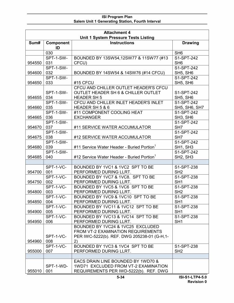
ISI Program Plan Salem Unit 1 Generating Station, Fourth Interval
5-34 ISI-S1-LTP4-5.0 Revision 0
Attachment 4 Unit 1 System Pressure Tests Listing
Sum# Component ID
Instructions Drawing
030 SH6
954550 SPT-1-SW-031
BOUNDED BY 13SW54,12SW77 & 11SW77 (#13 CFCU)
S1-SPT-242 SH6
954600 SPT-1-SW-032 BOUNDED BY 14SW54 & 14SW76 (#14 CFCU)
S1-SPT-242 SH5, SH6
954650 SPT-1-SW-033 #15 CFCU
S1-SPT-242 SH5, SH6
954655 SPT-1-SW-034
CFCU AND CHILLER OUTLET HEADER'S CFCU OUTLET HEADER SH 6 & CHILLER OUTLET HEADER SH 5
S1-SPT-242 SH5, SH6
954660 SPT-1-SW-035
CFCU AND CHILLER INLET HEADER'S INLET HEADER SH 5 & 6
S1-SPT-242 SH5, SH6, SH7
954665 SPT-1-SW-036
#11 COMPONENT COOLING HEAT EXCHANGER
S1-SPT-242 SH3, SH6
954670 SPT-1-SW-037 #11 SERVICE WATER ACCUMULATOR
S1-SPT-242 SH7
954675 SPT-1-SW-038 #12 SERVICE WATER ACCUMULATOR
S1-SPT-242 SH7
954680 SPT-1-SW-039 #11 Service Water Header - Buried Portion1
S1-SPT-242 SH1, SH3
954685 SPT-1-SW-040 #12 Service Water Header - Buried Portion1
S1-SPT-242 SH2, SH3
954700 SPT-1-VC-001
BOUNDED BY 1VC1 & 1VC2 SPT TO BE PERFORMED DURING LLRT.
S1-SPT-238 SH2
954750 SPT-1-VC-002
BOUNDED BY 1VC7 & 1VC8. SPT TO BE PERFORMED DURING LLRT.
S1-SPT-238 SH1
954800 SPT-1-VC-003
BOUNDED BY 1VC5 & 1VC6 SPT TO BE PERFORMED DURING LLRT.
S1-SPT-238 SH2
954850 SPT-1-VC-004
BOUNDED BY 1VC9 & 1VC10 SPT TO BE PERFORMED DURING LLRT.
S1-SPT-238 SH1
954900 SPT-1-VC-005
BOUNDED BY 1VC11 & 1VC12 SPT TO BE PERFORMED DURING LLRT.
S1-SPT-238 SH1
954950 SPT-1-VC-006
BOUNDED BY 1VC13 & 1VC14 SPT TO BE PERFORMED DURING LLRT.
S1-SPT-238 SH1
954960 SPT-1-VC-008
BOUNDED BY 1VC24 & 1VC25 EXCLUDED FROM VT-2 EXAMINATION REQUIREMENTS PER IWC-5222(b). REF. DWG 205238-01 (G-H,1-2)
955000 SPT-1-VC-007
BOUNDED BY 1VC3 & 1VC4 SPT TO BE PERFORMED DURING LLRT.
S1-SPT-238 SH2
955010 SPT-1-WD-001
EACS DRAIN LINE BOUNDED BY 1WD70 & 1WD71 EXCLUDED FROM VT-2 EXAMINATION REQUIREMENTS PER IWD-5222(b). REF. DWG

ISI Program Plan Salem Unit 1 Generating Station, Fourth Interval
5-35 ISI-S1-LTP4-5.0 Revision 0
Attachment 4 Unit 1 System Pressure Tests Listing
Sum# Component ID
Instructions Drawing
205227-01 (H,10).
955050 SPT-1-WG-001
WASTE GAS HEADERS AND GAS ANALYZER AND SUCTION AND DISCHARGE HEADERS. Examination performed on separate sections of system and recorded under the following Sum numbers 958200 - 958210 - 958220 - 958230 - 958240 - 958250 - 958260 & 958265.
S1-SPT-240 SH2, SH3
955055 SPT-1-WG-002
BOUNDED BY 11-14 WGDT, 11 & 12 WGC AND SUCTION AND DISCHARGE HEADERS. Examination performed on separate sections of system and recorded under the following Sum numbers 958200 - 958210 - 958220 - 958230 - 958240 - 958250 - 958260 & 958265.
S1-SPT-240 SH2, SH3
955100 SPT-1-WL-001
BOUNDED BY 1WL98, 99 & 108 SPT TO BE PERFORMED DURING THE LLRT.
S1-SPT-239 SH3
955150 SPT-1-WL-002
BOUNDED BY 1SF22 & 1SF36 TO THE REFUELING CANAL
S1-SPT-239 SH3
955200 SPT-1-WL-003 BOUNDED BY 1WL96 & 1WL97
S1-SPT-239 SH3
955250 SPT-1-WL-004 BOUNDED BY 1WL12 & 1WL13
S1-SPT-239 SH3
955300 SPT-1-WL-005 BOUNDED BY 1WL16 & 1WL17
S1-SPT-239 SH3
955350 SPT-1-WR-001 BOUNDED BY 1WR80 & 1WR81
S1-SPT-201 SH1
954665 SPT-1-SW-036
#11 COMPONENT COOLING HEAT EXCHANGER
S1-SPT-242 SH3, SH6
954670 SPT-1-SW-037 #11 SERVICE WATER ACCUMULATOR
S1-SPT-242 SH7
954675 SPT-1-SW-038 #12 SERVICE WATER ACCUMULATOR
S1-SPT-242 SH7
954680 SPT-1-SW-039 #11 Service Water Header - Buried Portion1
S1-SPT-242 SH1, SH3
954685 SPT-1-SW-040 #12 Service Water Header - Buried Portion1
S1-SPT-242 SH2, SH3
954700 SPT-1-VC-001
BOUNDED BY 1VC1 & 1VC2 SPT TO BE PERFORMED DURING LLRT.
S1-SPT-238 SH2
954750 SPT-1-VC-002
BOUNDED BY 1VC7 & 1VC8. SPT TO BE PERFORMED DURING LLRT.
S1-SPT-238 SH1
954800 SPT-1-VC-003
BOUNDED BY 1VC5 & 1VC6 SPT TO BE PERFORMED DURING LLRT.
S1-SPT-238 SH2

ISI Program Plan Salem Unit 1 Generating Station, Fourth Interval
5-36 ISI-S1-LTP4-5.0 Revision 0
Attachment 4 Unit 1 System Pressure Tests Listing
Sum# Component ID
Instructions Drawing
954850 SPT-1-VC-004
BOUNDED BY 1VC9 & 1VC10 SPT TO BE PERFORMED DURING LLRT.
S1-SPT-238 SH1
954900 SPT-1-VC-005
BOUNDED BY 1VC11 & 1VC12 SPT TO BE PERFORMED DURING LLRT.
S1-SPT-238 SH1
954950 SPT-1-VC-006
BOUNDED BY 1VC13 & 1VC14 SPT TO BE PERFORMED DURING LLRT.
S1-SPT-238 SH1
954960 SPT-1-VC-008
BOUNDED BY 1VC24 & 1VC25 EXCLUDED FROM VT-2 EXAMINATION REQUIREMENTS PER IWC-5222(b). REF. DWG 205238-01 (G-H,1-2)
955000 SPT-1-VC-007
BOUNDED BY 1VC3 & 1VC4 SPT TO BE PERFORMED DURING LLRT.
S1-SPT-238 SH2
955010 SPT-1-WD-001
EACS DRAIN LINE BOUNDED BY 1WD70 & 1WD71 EXCLUDED FROM VT-2 EXAMINATION REQUIREMENTS PER IWD-5222(b). REF. DWG 205227-01 (H,10).
955050 SPT-1-WG-001
WASTE GAS HEADERS AND GAS ANALYZER AND SUCTION AND DISCHARGE HEADERS. Examination performed on separate sections of system and recorded under the following Sum numbers 958200 - 958210 - 958220 - 958230 - 958240 - 958250 - 958260 & 958265.
S1-SPT-240 SH2, SH3
955055 SPT-1-WG-002
BOUNDED BY 11-14 WGDT, 11 & 12 WGC AND SUCTION AND DISCHARGE HEADERS. Examination performed on separate sections of system and recorded under the following Sum numbers 958200 - 958210 - 958220 - 958230 - 958240 - 958250 - 958260 & 958265.
S1-SPT-240 SH2, SH3
955100 SPT-1-WL-001
BOUNDED BY 1WL98, 99 & 108 SPT TO BE PERFORMED DURING THE LLRT.
S1-SPT-239 SH3
955150 SPT-1-WL-002
BOUNDED BY 1SF22 & 1SF36 TO THE REFUELING CANAL
S1-SPT-239 SH3
955200 SPT-1-WL-003 BOUNDED BY 1WL96 & 1WL97
S1-SPT-239 SH3
955250 SPT-1-WL-004 BOUNDED BY 1WL12 & 1WL13
S1-SPT-239 SH3
955300 SPT-1-WL-005 BOUNDED BY 1WL16 & 1WL17
S1-SPT-239 SH3
955350 SPT-1-WR-001 BOUNDED BY 1WR80 & 1WR81
S1-SPT-201 SH1
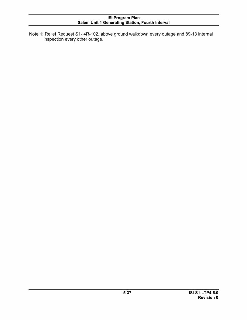
ISI Program Plan Salem Unit 1 Generating Station, Fourth Interval
5-37 ISI-S1-LTP4-5.0 Revision 0
Note 1: Relief Request S1-I4R-102, above ground walkdown every outage and 89-13 internal inspection every other outage.
ISI Program Plan Salem Unit 1 Generating Station, Fourth Interval
6-1 ISI-S1-LTP4-6.0 Revision 0
6.0 CONTAINMENT ISI PLAN
The Salem Unit 1 CISI Plan is documented separately in CISI-SC-LTP2.

ISI Program Plan Salem Unit 1 Generating Station, Fourth Interval
7-1 ISI-S1-LTP4-7.0 Revision 0
7.0 COMPONENT SUMMARY TABLES
7.1 Inservice Inspection Summary Tables
Table 7.1-1 provides a summary of the ASME Section XI pressure retaining components, supports, system pressure testing, and augmented program components for the Fourth ISI Interval at Salem Unit 1.
The table provides the following information:
Examination Category (with Examination
Category Description)
Item Number (or Augmented
Number)
Description Exam Requirements
Relief Request/
TAP Number
Notes
(1) (2) (3) (4) (5) (6)
The table associated with component supports (Category F-A) additionally provides information on the Support Types.
(1) Examination Category (with Examination Category Description):
The Examination Category and description as identified in ASME Section XI, Tables IWB-2500-1, IWC-2500-1, IWD-2500-1, and IWF-2500-1. Only those Examination Categories applicable to Salem Unit 1 are included.
Note that Examination Category “R-A” from Code Case N-578-1 is used in lieu of ASME Section XI Examination Categories B-F, B-J, and C-F-2 to identify Class 1 and 2 piping structural elements for the RI-ISI Program.
(2) Item Number (or Augmented Number):
The Item Number as identified in ASME Section XI, Tables IWB-2500-1, IWC-2500-1, IWD-2500-1, and IWF-2500-1. Only those Item Numbers applicable to Salem Unit 1 are included.
Note that for piping structural elements under the RI-ISI Program (Category R-A), the RI-ISI Item Number from Code Case N-578-1 is included.
Augmented identification numbers have been developed to identify Augmented ISI examinations and other Salem Unit 1 commitments.

ISI Program Plan Salem Unit 1 Generating Station, Fourth Interval
7-2 ISI-S1-LTP4-7.0 Revision 0
(3) Description:
The description as identified in ASME Section XI, Tables IWB-2500-1, IWC-2500-1, IWD-2500-1, and IWF-2500-1.
Note that for Risk-Informed piping examinations, a description of the RI-ISI Item Number is included.
Note for Augmented inspection commitments, a description of the Augmented requirement is included.
(4) Exam Requirements:
The examination method required by ASME Section XI, Tables IWB-2500-1, IWC-2500-1, IWD-2500-1, and IWF-2500-1.
The examination requirements for piping structural elements under the RI-ISI Program that are in accordance with the EPRI Topical Reports TR-112657, Rev. B-A, and Code Case N-578-1.
The examination requirements required for augmented inspections.
To ensure Code compliance for examination requirements also refer to Salem Unit 1’s ISI Selection Document Sections 2.0, 3.0, 4.0, 6.0, 7.0, and 8.0, as applicable.
(5) Relief Request/Technical Approach & Position Number
A listing of Relief Request/TAP Numbers applicable to specific components, the ASME Section XI Item Number, RI-ISI Item Number, or Augmented Number is included. Non-component specific Relief Requests and TAPs are not listed. If a Relief Request/TAP Number is included, refer to the corresponding relief request in Section 8.0 or the technical approach and position in Section 2.5.
(6) Notes
A listing of program notes applicable to the ASME Section XI Item Number, RI-ISI Item Number, or Augmented Number is included. If a program note number is provided, see the corresponding program note in Table 7.1-2.

ISI Program Plan Salem Unit 1 Generating Station, Fourth Interval
TABLE 7.1-1
INSERVICE INSPECTION SUMMARY TABLE
7-3 ISI-S1-LTP4-7.0 Revision 0
Examination Category
(with Category Description) Item
Number Description Exam
Requirements Relief Request/ TAP Number
Notes
B-A Pressure Retaining
Welds in Reactor Vessel
B1.11 Circumferential Shell Welds (Reactor Vessel) Volumetric S1-I3R-93 4 B1.12 Longitudinal Shell Welds (Reactor Vessel) Volumetric S1-I3R-93 4 B1.21 Circumferential Head Welds (Reactor Vessel) Volumetric S1-I3R-93 4 B1.22 Meridional Head Welds (Reactor Vessel) Volumetric S1-I3R-93 4 B1.30 Shell-to-Flange Weld (Reactor Vessel) Volumetric S1-I3R-93 4
B-B Pressure Retaining Welds in Vessels Other Than
Reactor Vessels
B2.11 Circumferential Shell-to-Head Welds (Pressurizer) Volumetric B2.12 Longitudinal Shell-to-Head Welds (Pressurizer) Volumetric B2.40 Tubesheet-to-Head Weld (Steam Generator Primary
Side) Volumetric
B-D Full Penetration Welds of Nozzles in Vessels
B3.90 Nozzle-to-Vessel Welds (Reactor Vessel) Volumetric B3.100 Nozzle Inside Radius Section (Reactor Vessel) Volumetric B3.120 Nozzle Inside Radius Section (Pressurizer) Volumetric or
Visual 1
B3.140 Nozzle Inside Radius Section (Steam Generators Primary Side)
Volumetric or Visual
1
B-G-1 B6.10 Closure Head Nuts (Reactor Vessel) Visual, VT-1 Pressure Retaining B6.20 Closure Studs (Reactor Vessel) Volumetric
Bolting, Greater Than B6.40 Threads in Flange (Reactor Vessel) Volumetric 2 in. In Diameter B6.50 Closure Washers, Bushings (Reactor Vessel) Visual, VT-1
B6.180 Bolts and Studs (Pumps) Volumetric B6.190 Flange Surface, when connection disassembled
(Pumps) Visual, VT-1
B-G-2 Pressure Retaining Bolting 2 in. and Less Diameter
B7.20 Bolts, Studs, and Nuts (Pressurizer) Visual, VT-1 B7.30 Bolts, Studs, and Nuts (Steam Generators) Visual, VT-1 B7.50 Bolts, Studs, and Nuts (Piping) Visual, VT-1 B7.70 Bolts, Studs, and Nuts (Valves) Visual, VT-1

ISI Program Plan Salem Unit 1 Generating Station, Fourth Interval
TABLE 7.1-1
INSERVICE INSPECTION SUMMARY TABLE
7-4 ISI-S1-LTP4-7.0 Revision 0
Examination Category
(with Category Description) Item
Number Description Exam
Requirements Relief Request/ TAP Number
Notes
B-K Welded Attachments for Vessels, Piping, Pumps,
and Valves
B10.10 Welded Attachments (Pressure Vessels) Surface or Volumetric
B10.20 Welded Attachments (Piping) Surface
B10.30 Welded Attachments (Pumps) Surface B-L-1
Pump Casing Welds B12.10 Casing Welds (Pumps) Visual, VT-1
B-L-2 B12.20 Casings (Pumps) Visual, VT-3 Pump Casings
B-M-2 B12.50 Valve Bodies (Exceeding NPS 4) (Valves) Visual, VT-3 Valve Bodies

ISI Program Plan Salem Unit 1 Generating Station, Fourth Interval
TABLE 7.1-1
INSERVICE INSPECTION SUMMARY TABLE
7-5 ISI-S1-LTP4-7.0 Revision 0
Examination Category
(with Category Description) Item
Number Description Exam
Requirements Relief Request/ TAP Number
Notes
B-N-1 B13.10 Vessel Interior (Reactor Vessel) Visual, VT-3 Interior of Reactor Vessel
B-N-2 Welded Core
B13.60 Interior Attachments Beyond Beltline Region (Reactor Vessel)
Visual, VT-3 S1-I3R-95 4
Support Structures and Interior Attachments to Reactor Vessels
B-N-3
Removable Core Support Structures B13.70 Core Support Structure Visual, VT-3 S1-I3R-95 4
B-O Pressure Retaining Welds in
Control Rod Housings
B14.20 Welds in CRD Housing (Reactor Vessel) (10% of Peripheral CRD Housings)
Volumetric or Surface
5
B-P All Pressure Retaining
Components
B15.10 Pressure Retaining Components Visual, VT-2 SM1-I4T-01
B-Q Steam Generator Tubing
B16.20 Steam Generator Tubing in U-Tube Design Volumetric 6

ISI Program Plan Salem Unit 1 Generating Station, Fourth Interval
TABLE 7.1-1
INSERVICE INSPECTION SUMMARY TABLE
7-6 ISI-S1-LTP4-7.0 Revision 0
Examination Category (with Category Description)
Item Number
Description Exam Requirements
Relief Request/ TAP Number
Notes
C-A Pressure Retaining Welds
in Pressure Vessels
C1.10 Shell Circumferential Welds (Pressure Vessels) Volumetric 7
C1.20 Head Circumferential Welds (Pressure Vessels) Volumetric 7 C1.30 Tubesheet-to-Shell Welds (Pressure Vessels) Volumetric 7 C2.21 Nozzle-to-Shell (Nozzle to Head or Nozzle to Nozzle) Volumetric &
Welds in Vessels Without Reinforcing Plate, and Greater Than ½" Nominal Thickness (Pressure Vessels)
Surface 7
C2.22 Nozzle Inside Radius Section in Vessels Without
Reinforcing Plate, and Greater Than ½" Nominal Thickness (Pressure Vessels)
Volumetric 7
C-C
Welded Attachments for Vessels, Piping, Pumps, and Valve
C3.10 Welded Attachments (Pressure Vessels) Surface C3.20 Welded Attachments (Piping) Surface C3.30 Welded Attachments (Pumps) Surface C3.40 Welded Attachments (Valves) Surface
C-D Pressure Retaining
Bolting, Greater Than 2 in. In Diameter
C4.10 Bolts and Studs (Pressure Vessels) Volumetric 8 C4.40 Bolts and Studs (Valves) Volumetric 8
C-G Pressure Retaining Welds
in Pumps and Valves
C6.10 Casing Welds (Pumps) Surface C6.20 Body Welds (Valves) Surface
C-H C7.10 System Leakage Test (IWC-5220) Visual, VT-2 All Pressure
Retaining Components

ISI Program Plan Salem Unit 1 Generating Station, Fourth Interval
TABLE 7.1-1
INSERVICE INSPECTION SUMMARY TABLE
7-7 ISI-S1-LTP4-7.0 Revision 0
Examination Category
(with Category Description) Item
Number Description Exam
Requirements Relief Request/ TAP Number
Notes
D-A Welded Attachments for Vessels, Piping, Pumps,
and Valves
D1.10 Welded Attachments (Pressure Vessels) Visual, VT-1
D1.20 Welded Attachments (Piping) Visual, VT-1
D1.30 Welded Attachments (Pumps) Visual, VT-1
D-B D2.10 System Leakage Test (IWD-5221) Visual, VT-2 S1-I4R-102 All Pressure
Retaining Components

ISI Program Plan Salem Unit 1 Generating Station, Fourth Interval
TABLE 7.1-1
INSERVICE INSPECTION SUMMARY TABLE
7-8 ISI-S1-LTP4-7.0 Revision 0
Examination Category
(with Category Description) Item
Number Description Exam
Requirements Support
Type Code
Support Type Description
Relief Request/ TAP Number
Notes
F-A Supports
F1.10 Class 1 Piping Supports Visual, VT-3 A ANCHORS E STRUTS H CONSTANT
SUPPORTS
I VAR. SUPPORTS K PUMP, TANK, HX, OR
SLIDING SUPPORTS
L HANGERS M SUPPORTS N GUIDES P CONTAINMENT
PENETRATION PIPING ANCHORS
S SNUBBER SUPPORTS F1.20 Class 2 Piping Supports Visual, VT-3 A ANCHORS
E STRUTS G RESTRAINTS H CONSTANT SUPPORTS I VAR. SUPPORTS
L HANGERS M SUPPORTS N GUIDES O VIBRATION DAMPERS P CONTAINMENT
PENETRATION PIPING ANCHORS
S SNUBBER SUPPORTS
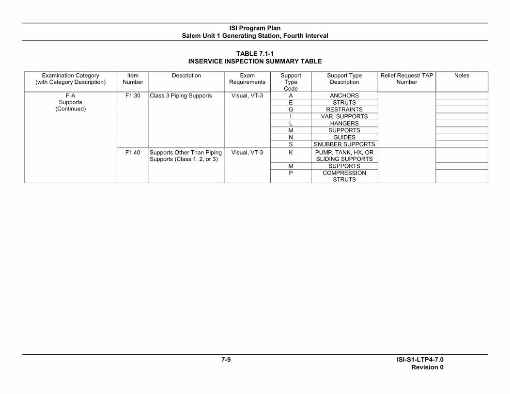
ISI Program Plan Salem Unit 1 Generating Station, Fourth Interval
TABLE 7.1-1
INSERVICE INSPECTION SUMMARY TABLE
7-9 ISI-S1-LTP4-7.0 Revision 0
Examination Category
(with Category Description) Item
Number Description Exam
Requirements Support
Type Code
Support Type Description
Relief Request/ TAP Number
Notes
F-A Supports
(Continued)
F1.30 Class 3 Piping Supports Visual, VT-3 A ANCHORS E STRUTS G RESTRAINTS I VAR. SUPPORTS L HANGERS M SUPPORTS N GUIDES S SNUBBER SUPPORTS
F1.40 Supports Other Than Piping Supports (Class 1, 2, or 3)
Visual, VT-3 K PUMP, TANK, HX, OR SLIDING SUPPORTS
M SUPPORTS P COMPRESSION
STRUTS
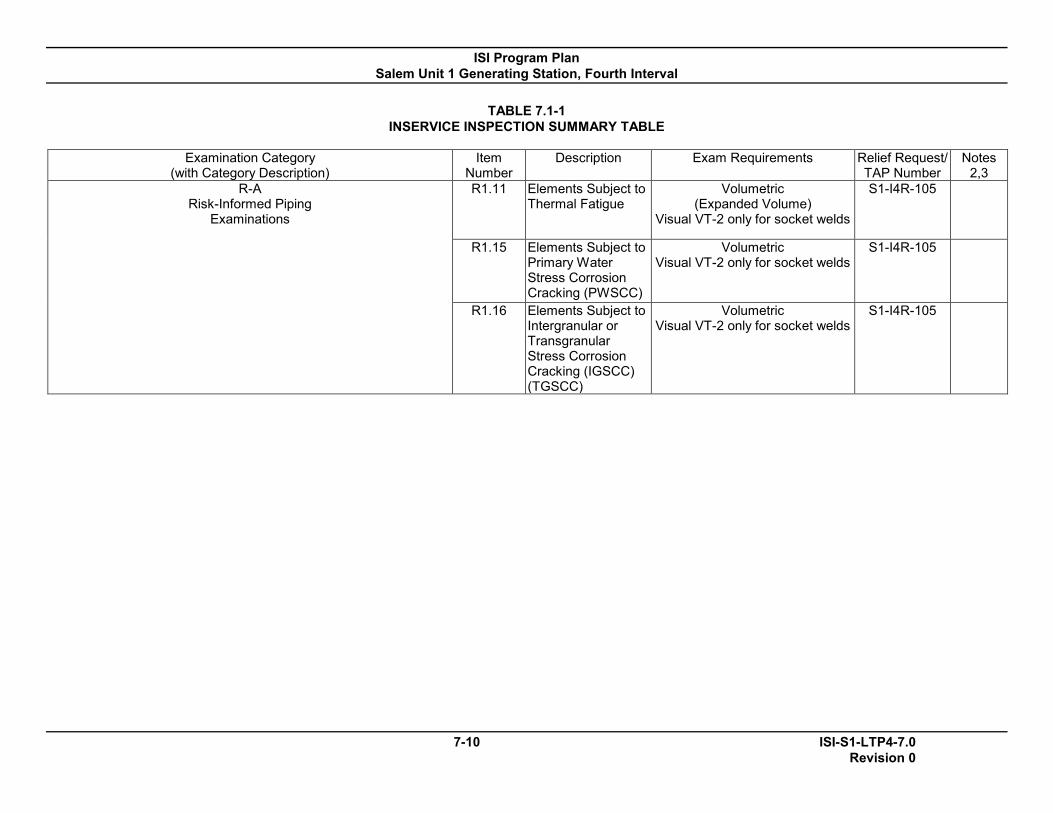
ISI Program Plan Salem Unit 1 Generating Station, Fourth Interval
TABLE 7.1-1
INSERVICE INSPECTION SUMMARY TABLE
7-10 ISI-S1-LTP4-7.0 Revision 0
Examination Category
(with Category Description) Item
Number Description Exam Requirements Relief Request/
TAP Number Notes
2,3 R-A
Risk-Informed Piping Examinations
R1.11 Elements Subject to Thermal Fatigue
Volumetric (Expanded Volume)
Visual VT-2 only for socket welds
S1-I4R-105
R1.15 Elements Subject to Primary Water Stress Corrosion Cracking (PWSCC)
Volumetric Visual VT-2 only for socket welds
S1-I4R-105
R1.16 Elements Subject to Intergranular or Transgranular Stress Corrosion Cracking (IGSCC) (TGSCC)
Volumetric Visual VT-2 only for socket welds
S1-I4R-105

ISI Program Plan Salem Unit 1 Generating Station, Fourth Interval
TABLE 7.1-1
INSERVICE INSPECTION SUMMARY TABLE
7-11 ISI-S1-LTP4-7.0 Revision 0
Examination Category
(with Category Description) Item
Number Description Exam Requirements Relief Request/
TAP Number Notes
2,3 R-A
Risk-Informed Piping Examinations (Continued)
R1.18 Elements Subject to Flow Accelerated Corrosion (FAC)
Owner’s FAC Program S1-I4R-105
R1.19 Elements Subject to External Chloride Stress Corrosion Cracking (ECSCC)
Surface S1-I4R-105
R1.20 Elements not Subject to a Damage Mechanism
Volumetric (Expanded Volume)
Visual VT-2 only for socket welds
S1-I4R-105

ISI Program Plan Salem Unit 1 Generating Station, Fourth Interval
TABLE 7.1-1
INSERVICE INSPECTION SUMMARY TABLE
7-12 ISI-S1-LTP4-7.0 Revision 0
Examination Category
(with Category Description) Augmented Examination
Description Exam Requirements
Relief Request/ TAP Number
Notes
Augmented Components
NUREG 0578 PSEG committed to perform an examination to reduce potential and existing leakage paths from systems outside containment that would or could contain radioactive fluids during a serious transient or accident for the Residual Heat Removal, Safety Injection, Containment Spray, Chemical Volume and Control, Waste Gas, Waste Liquid, and Sampling Systems.
Leakage Tests and Visual
Examinations
Reg. Guide 1.14 Reactor Coolant Pump Flywheel Examination Volumetric or Surface
Reactor Coolant Pump Shaft
Info Gram IG-02-04 and subsequent Industry RCP shaft failures resulted in program to examine all pump shafts when motors disassembled and rebuilt.
Volumetric
MRP-139 Material Reliability Program: Primary System Piping Butt Weld Inspection and Evaluation Guideline
Volumetric and Bare Metal
visual
MRP Letter 2004-04
Reactor Vessel Bottom Mounted Instrument nozzle Integrated Industry Inspection Plan
Volumetric, Visual EVT-1
and Eddy Current ET
9
WCAP-16913-P R1
Operability Assessment and Plant Applicability Evaluation for Pressurizer Heater Sleeve Leakage in Westinghouse Designed Pressurizers
Visual VT-2
MRP-192 Materials Reliability Program: Assessment of RHR Mixing Tee Thermal Fatigue in PWR Plants
Volumetric
OE15222 Cracks in Safety Injection Accumulators Bare Metal Visual
Code Case N-722
Additional Examinations for PWR Pressure Retaining Welds in Class 1 Components Fabricated with Alloy 600/82/182 Materials
Bare Metal Visual
Code Case N-729-1
Alternative Examination Requirements for PWR Reactor Vessel Upper Heads with Nozzles Having Pressure-Retaining Partial-Penetration Welds
Volumetric, Surface, and Bare Metal
Visual
10
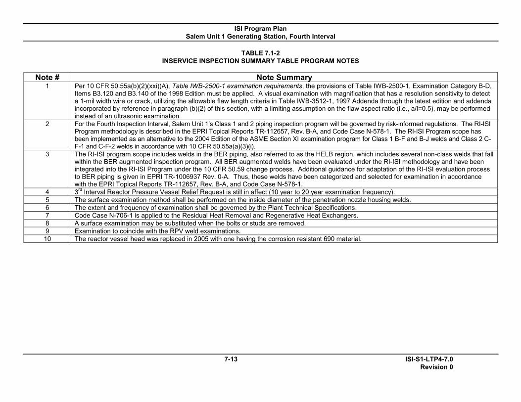
ISI Program Plan Salem Unit 1 Generating Station, Fourth Interval
TABLE 7.1-2
INSERVICE INSPECTION SUMMARY TABLE PROGRAM NOTES
7-13 ISI-S1-LTP4-7.0 Revision 0
Note # Note Summary
1 Per 10 CFR 50.55a(b)(2)(xxi)(A), Table IWB-2500-1 examination requirements, the provisions of Table IWB-2500-1, Examination Category B-D, Items B3.120 and B3.140 of the 1998 Edition must be applied. A visual examination with magnification that has a resolution sensitivity to detect a 1-mil width wire or crack, utilizing the allowable flaw length criteria in Table IWB-3512-1, 1997 Addenda through the latest edition and addenda incorporated by reference in paragraph (b)(2) of this section, with a limiting assumption on the flaw aspect ratio (i.e., a/l=0.5), may be performed instead of an ultrasonic examination.
2 For the Fourth Inspection Interval, Salem Unit 1’s Class 1 and 2 piping inspection program will be governed by risk-informed regulations. The RI-ISI Program methodology is described in the EPRI Topical Reports TR-112657, Rev. B-A, and Code Case N-578-1. The RI-ISI Program scope has been implemented as an alternative to the 2004 Edition of the ASME Section XI examination program for Class 1 B-F and B-J welds and Class 2 C-F-1 and C-F-2 welds in accordance with 10 CFR 50.55a(a)(3)(i).
3 The RI-ISI program scope includes welds in the BER piping, also referred to as the HELB region, which includes several non-class welds that fall within the BER augmented inspection program. All BER augmented welds have been evaluated under the RI-ISI methodology and have been integrated into the RI-ISI Program under the 10 CFR 50.59 change process. Additional guidance for adaptation of the RI-ISI evaluation process to BER piping is given in EPRI TR-1006937 Rev. 0-A. Thus, these welds have been categorized and selected for examination in accordance with the EPRI Topical Reports TR-112657, Rev. B-A, and Code Case N-578-1.
4 3rd Interval Reactor Pressure Vessel Relief Request is still in affect (10 year to 20 year examination frequency). 5 The surface examination method shall be performed on the inside diameter of the penetration nozzle housing welds. 6 The extent and frequency of examination shall be governed by the Plant Technical Specifications. 7 Code Case N-706-1 is applied to the Residual Heat Removal and Regenerative Heat Exchangers. 8 A surface examination may be substituted when the bolts or studs are removed. 9 Examination to coincide with the RPV weld examinations. 10 The reactor vessel head was replaced in 2005 with one having the corrosion resistant 690 material.

ISI Program Plan Salem Unit 1 Generating Station, Fourth Interval
8-1 ISI-S1-LTP4-8.0 Revision 0
8.0 RELIEF REQUESTS FROM ASME SECTION XI
This section contains Requests for Alternative written per 10 CFR 50.55a(a)(3)(i) for situations where alternatives to ASME Section XI requirements provide an acceptable level of quality and safety; per 10 CFR 50.55a(a)(3)(ii) for situations where compliance with ASME Section XI requirements results in a hardship or an unusual difficulty without a compensating increase in the level of quality and safety; and per 10 CFR 50.55a(g)(5)(iii) for situations where ASME Section XI requirements are considered impractical. These requests are also referred to as “relief requests.”
8.1 Active Third Interval Requests for Alternative Salem Unit 1 requested and received permission to establish an
examination frequency of 20 years for certain reactor vessel components in the Third ISI Interval. Relief Requests S1-I3R-93 and SC-I3R-95 were approved by NRC Safety Evaluation (SE) letter dated February 22, 2010 during the Third ISI Interval and remain in effect during the Fourth ISI Interval time period as indicated in the NRC SE.
8.2 Format
Requests for Alternative will be in accordance with NEI and NRC
established guidelines. Each request identification number will include the following:
Ex. S1-I4R-111
S1- Salem Unit 1 S2- Salem Unit 2 SC- Salem Common
I for Interval, 4 for Interval # & R for Relief Request
Year 9 = 2009 10 = 2010 11 = 2011 12 = 2012
Sequential Number

ISI Program Plan Salem Unit 1 Generating Station, Fourth Interval
8-2 ISI-S1-LTP4-8.0 Revision 0
Documentation will be prepared in a manner to assure the following attributes are addressed, as necessary:
ASME Code Component(s) Affected
Basis of Alternative for Providing Acceptable Level of Quality and Safety
Applicable Code Edition and Addenda
Applicable Code Requirement
Proposed Alternative Duration of Proposed Alternative
Precedents References
8.3 An index for Salem Unit 1 Requests for Alternative for the Fourth ISI Interval is included in Table 8.0-1.
8.4 The following Requests for Alternative may be subject to revision throughout the inspection interval and subject to NRC approval. Additionally new requests may be added and subject to NRC approval. Alternatives under 10 CFR 50.55a(a)(3) require NRC approval prior to implementation where as Relief Requests under 10 CFR 50.55a(g)(5) typically do not, since these are usually used for limited coverage examinations and submitted after the examination is complete and credited.
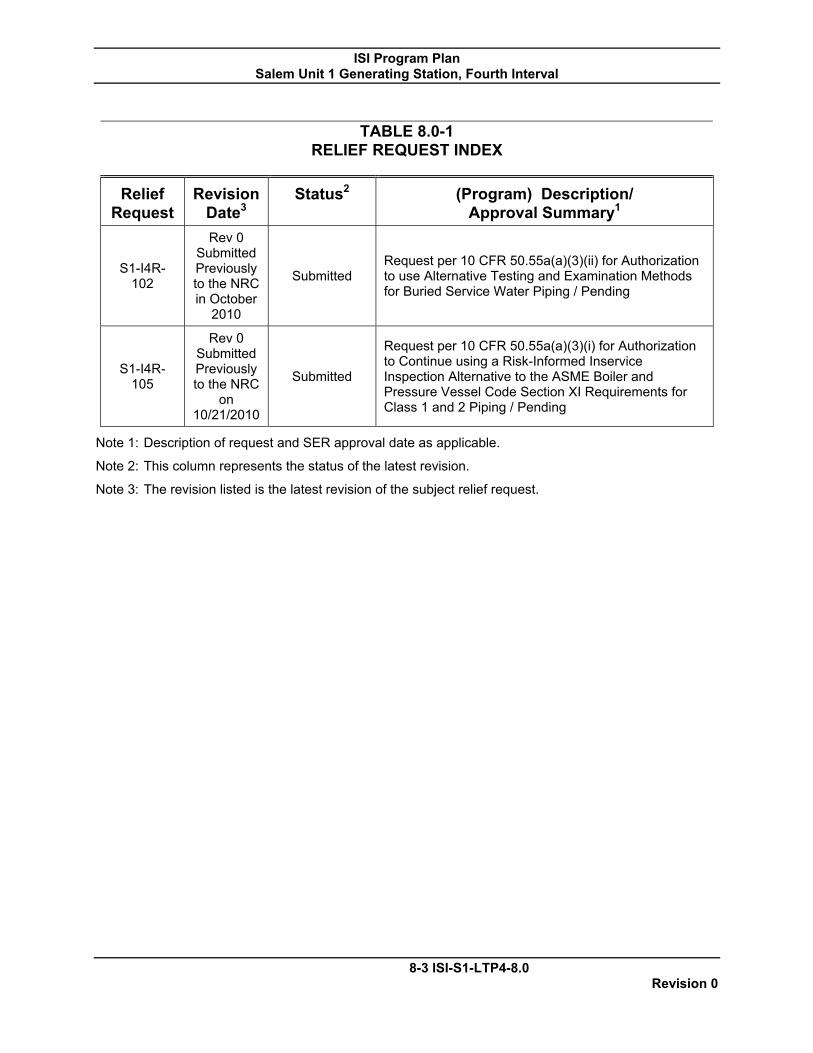
ISI Program Plan Salem Unit 1 Generating Station, Fourth Interval
8-3 ISI-S1-LTP4-8.0 Revision 0
TABLE 8.0-1
RELIEF REQUEST INDEX
Relief Request
Revision Date3
Status2 (Program) Description/ Approval Summary1
S1-I4R-102
Rev 0 Submitted Previously to the NRC in October
2010
Submitted Request per 10 CFR 50.55a(a)(3)(ii) for Authorization to use Alternative Testing and Examination Methods for Buried Service Water Piping / Pending
S1-I4R-105
Rev 0 Submitted Previously to the NRC
on 10/21/2010
Submitted
Request per 10 CFR 50.55a(a)(3)(i) for Authorization to Continue using a Risk-Informed Inservice Inspection Alternative to the ASME Boiler and Pressure Vessel Code Section XI Requirements for Class 1 and 2 Piping / Pending
Note 1: Description of request and SER approval date as applicable.
Note 2: This column represents the status of the latest revision.
Note 3: The revision listed is the latest revision of the subject relief request.

ISI Program Plan Salem Unit 1 Generating Station, Fourth Interval
Relief Request –S1-I4R-102
8-4 ISI-S1-LTP4-8.0 Revision 0
1. ASME Code Component(s) Affected
Code Class: 3 Examination Category: D-B Item Number: D2.10 Description: Buried portions of the 11 & 12 Nuclear Service
Water (SW) Supply Headers Unit/Inspection: Salem Unit 1/Fourth (4th) 10-Year Interval
2. Applicable Code Edition and Addenda
American Society of Mechanical Engineers (ASME) Boiler and Pressure Vessel Code, Section XI, "Rules for Inservice Inspection and Testing of Components of Light-Water Cooled Plants," 2004 Edition. The fourth interval will begin on May 20, 2011 and will end on May 20, 2021.
3. Applicable Code Requirement
ASME Section XI IWD-2500 Table IWD-2500-1, Inspection Program B, requires system leakage test of pressure retaining boundary of Class 3 components once each period of the lSI ten-year interval. The system pressure tests and visual examinations shall be conducted in accordance with IWA-5000. A portion of the Service Water Supply Piping is buried and IWA-5244 applies.
ASME Section XI IWA-5244, Buried Component, states:
(b) For buried components where a VT-2 visual examination cannot be
performed, the examination requirement is satisfied by the following:
(1) The system pressure test for buried components that are isolable by means of valves shall consist of a test that determines the rate of pressure loss. Alternatively, the test may determine the change in flow between the ends of the buried components. The acceptable rate of pressure loss or flow shall be established by the owner.
(2) The system pressure test for nonisolable buried components shall
consist of a test to confirm that flow during operation is not impaired.
4. Reason for Request

ISI Program Plan Salem Unit 1 Generating Station, Fourth Interval
Relief Request –S1-I4R-102
8-5 ISI-S1-LTP4-8.0 Revision 0
The requirements of IWA-5244 have been the subject of a number of relief requests, as cited in Section 7.0 and NRC violations as cited in Section 8.0 of this request. The alternative proposed in this request will eliminate the risk of misinterpreting (or misapplying) the requirements of either IWA-5244(b)(1) or IWA-5244(b)(2), and will eliminate or minimize the risk of receiving additional NRC violations for non-compliance with the ASME Code, Section XI.
In order to perform the pressure testing necessary to meet the requirements of IWA5244 (b)(1), the butterfly valves which isolate 11 and 12 SW Nuclear Headers would need to be removed from the system and blind flanges installed to allow system isolation for pressure testing. The affected valves for 11 SW are 12SW20, 11SW21, 11SW22 and 11SW416 and for 12 SW the affected valves are 14SW20, 12SW21, 12SW22 and 12SW416. The cost and potential outage impact would result in hardship or unusual difficulty without compensating increase in level of quality or safety.
The following additional information is provided in support of this request:
1. Salem Generating Station, Unit 1 recently received a violation for the
failure to perform auxiliary feedwater (AFW) discharge piping system pressure tests on buried piping components in accordance with the ASME Code, Section XI, IWA5244. This NRC violation supports the need to seek relief from the requirement of IWA-5244(b)(1) of the 2004 Edition.
2. ASME has issued the following interpretations pertaining to IWA-5244:
a. On November 21,2007, ASME issued interpretation XI-1-07-28
that clarified examination requirements specified in IWA-5244(b)(2). The ASME interpretation is included as Attachment 3 to this request. Using this interpretation would require a licensee to comply with IWA-5244(b)(2) when testing buried components with valves that are not capable of isolating the portion of the component under test. The test required by IWA-5244(b)(2) is a test to confirm that flow during operation is not impaired.
b. On October 14, 2008, ASME issued interpretation XI-1-07-37
pertaining to the intent of IWA-5244(b)(1) as it applies to buried components with butterfly valves that are not designed to be leak-tight. This interpretation is included as Attachment 4 to this request. It supports the position that buried components with butterfly valves that are not leak-tight should receive an

ISI Program Plan Salem Unit 1 Generating Station, Fourth Interval
Relief Request –S1-I4R-102
8-6 ISI-S1-LTP4-8.0 Revision 0
unimpaired flow test.
5. Proposed Alternative and Basis for Use
The proposed alternative for testing the buried portion of Service Water piping in lieu of performing the periodic test required by IWA-5244(b)(1) shall consist of:
(1) A visual examination of the ground surface areas (includes surfaces of
asphalt or other pavement materials) above all SW piping buried in soil shall be performed during all current and subsequent inspection outages to detect evidence of throughwall leakage in the buried components. The system shall have been in operation at nominal operating conditions for at least 24 hours prior to performing the visual examinations, in lieu of performing the periodic test required by IWA-5244(b)(1). The ASME Section XI code only requires a pressure test once each period. Since the SW system is in-service for extended periods of time, any leakage would be readily identified by plant personnel performing routine inspections during rounds.
(2) Visual examination of the inside surface of all SW buried piping are
performed to ensure that piping is unobstructed and any evidence of piping degradation is identified and is evaluated or repaired.
The basis for the proposed alternative is as follows:
The requirements of IWA-5244 (b)(1) to perform a pressure drop test cannot be performed. The valves installed in the SW system that would isolate the piping for drop testing are butterfly valves and are not capable of the leak tightness required to perform a pressure drop test. There are no locations available for installation of flow measuring devices in the SW system near the buried portions that would be capable of measuring flow with sensitivity adequate for comparing flow at inlet and outlet of headers.
Industry experience indicates that neither the change in flow test IWA-5244(b)(1) nor the unimpaired flow test IWA-5244(b)(2) are sufficiently sensitive to detect small throughwall leakage in these buried components. This is due to relatively high system flow rates and accuracy of flow measurement instrumentation. As such, there is no appreciable difference between the level of quality and safety achieved by performing either of these tests.
Visual examinations of ground surface areas are capable of detecting potentially small through-wall leakage in the buried component. These visual examinations and visual examination of piping inside diameter provide reasonable assurance of the structural and leak-tight integrity of the buried components.

ISI Program Plan Salem Unit 1 Generating Station, Fourth Interval
Relief Request –S1-I4R-102
8-7 ISI-S1-LTP4-8.0 Revision 0
The SW Nuclear Headers are inspected under the GL 89-13 program, where valves are opened and/or removed and visual inspection and repairs are performed on entire buried SW Nuclear Header piping sections.
Inspection frequency information for these inspections is contained in Table 1.
Table 1: Current Inspection Frequency for Service Water
Inspection Frequency
Last Inspection Scope/actions
Next Inspection
36 Month (2RFO)
1R20 (S2010)
11 SW header: crawl through inspection
performed; inspection performed using remote video inspection system
1R22 (S2013)
36 Month (2RFO)
1R19 (F2008)
12 SW header, crawl through inspection
performed; inspection performed using remote video inspection system
1R21 (F2011 )
Most recent visual internal inspections on the buried portions of the 11 and 12 nuclear headers indicate that the piping is maintained in good condition and is unobstructed. The inspections cover approximately 300 feet for each header and spans from the service water intake structure to the auxiliary building. The buried piping is prestressed concrete cylinder piping with rubber and steel joints (reference PSEG drawing 219563, Attachment 5). Pursuant to 10CFR50.55a(a)(3)(ii), relief is requested because performing the tests on the Nuclear Service Water system at Salem in accordance with the code would result in hardship or unusual difficulty without compensating increase in level of quality or safety on the basis.
6. Duration of Proposed Alternative
The proposed alternative will be used for the fourth ten-year interval of the Inservice Inspection Program for Salem Unit 1, which begins May 20, 2011 and is currently scheduled to end on May 20,2021.
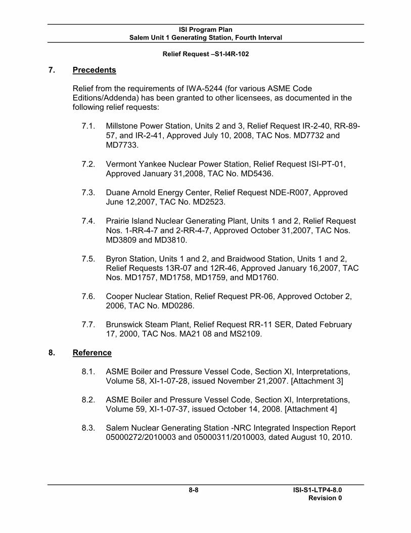
ISI Program Plan Salem Unit 1 Generating Station, Fourth Interval
Relief Request –S1-I4R-102
8-8 ISI-S1-LTP4-8.0 Revision 0
7. Precedents
Relief from the requirements of IWA-5244 (for various ASME Code Editions/Addenda) has been granted to other licensees, as documented in the following relief requests:
7.1. Millstone Power Station, Units 2 and 3, Relief Request IR-2-40, RR-89-57, and IR-2-41, Approved July 10, 2008, TAC Nos. MD7732 and MD7733.
7.2. Vermont Yankee Nuclear Power Station, Relief Request ISI-PT-01,
Approved January 31,2008, TAC No. MD5436.
7.3. Duane Arnold Energy Center, Relief Request NDE-R007, Approved June 12,2007, TAC No. MD2523.
7.4. Prairie Island Nuclear Generating Plant, Units 1 and 2, Relief Request
Nos. 1-RR-4-7 and 2-RR-4-7, Approved October 31,2007, TAC Nos. MD3809 and MD3810.
7.5. Byron Station, Units 1 and 2, and Braidwood Station, Units 1 and 2,
Relief Requests 13R-07 and 12R-46, Approved January 16,2007, TAC Nos. MD1757, MD1758, MD1759, and MD1760.
7.6. Cooper Nuclear Station, Relief Request PR-06, Approved October 2,
2006, TAC No. MD0286.
7.7. Brunswick Steam Plant, Relief Request RR-11 SER, Dated February 17, 2000, TAC Nos. MA21 08 and MS2109.
8. Reference
8.1. ASME Boiler and Pressure Vessel Code, Section XI, Interpretations, Volume 58, XI-1-07-28, issued November 21,2007. [Attachment 3]
8.2. ASME Boiler and Pressure Vessel Code, Section XI, Interpretations,
Volume 59, XI-1-07-37, issued October 14, 2008. [Attachment 4]
8.3. Salem Nuclear Generating Station -NRC Integrated Inspection Report 05000272/2010003 and 05000311/2010003, dated August 10, 2010.

ISI Program Plan Salem Unit 1 Generating Station, Fourth Interval
Relief Request –S1-I4R-102
8-9 ISI-S1-LTP4-8.0 Revision 0
Attachment 3
ASME Boiler and Pressure Vessel Code, Section XI, Interpretations Volume 58

ASME Boiler and Pressure Vessel Code SECTION Xl
INTERPRETATIONS Volume 58
Interpretations of the Code are distributed annually In July with the issuance of the edition and subsequent addenda. Interp/"etatlons post<:Ki in January at www.cstools.asme.orglinterpretstions are Included in the July distribution. Interpretations of Section Ill, Divisions 1 and 2, al'e part of the update service to Section Ill, Subsection NCA.
Interpretations Volumes 54 through 56 were included with the update service 10 the 2004 Edition of the Code; Volume 57 I" the first Interpretations volume to be included with the update se/vlce to the 2007 Edition.
Section I II·'" II·B lI·e II·D (Customary) II·D(Memc;) III·NCA 111·3 IV V VI VII YUH vm·2 VIII·3 IX X XI XII
Vol. 57 7/07 7/07
7/07
7/07 7/1:>7 7/07 7/07
7/07 7/07 7/07 7/07
7/07
8-10
7100 7/06
7108
710a 710a
7/06 7JOB 7/08 7/OB 7108 7108
" V'pJ.'S9
151..$1 ~LTP4-8.0 Revision 0

lSI Program Plan Salem Unit 1 Generating Station, Fourth Interval
Relief Request -$1 ~14R~1 02
ml:C'!'lON Xl -ll'f.I'lllR.PlUATIONS VOL. 58
fnterpretation: Xl-1-07-28
SubjeCt: lWA-S244 (1995 Edition Witb the 1995 Addenda Through the 2007 Bdlrlon) nat.. Iasuod: NOV1Wber 21,2007 File: IN()7-009
Question: Does the 1'Bquiremellt' of IW A-S244(b)(2) n;pply to burled components with valves that _ not capable of Ulolnliag the portion of tbs cmnponent under lest?
Reply: Y lIS,
.. :;" .....
. ,
sos
8-11 ISI~1-L TP4-8.0 Revision 0

ISI Program Plan Salem Unit 1 Generating Station, Fourth Interval
Relief Request –S1-I4R-102
8-12 ISI-S1-LTP4-8.0 Revision 0
Attachment 4
ASME Boiler and Pressure Vessel Code, Section XI, Interpretations Volume 59

ASME Boiler and Pn"!ssure Vessel C"':ode SECTION XI
INTERPRETATIONS Volume 59
Intet"pretatfons O'f the Code a('e distributed annually In July ~jth the issuance of the edltioi") and $t.~bsequent adclenda~ In1erprela.t:io.-.s pr..',h"!'d ,n January a1: ~w-.cstootg.a$rne.ot's""hl::tcrprcbl1:ion3 .fue included in the july distribution. In"terpl''eta-tron.5 of Sec:tio'n "Ill ... Di ..... -islons 1 und.2 1 ate part oT the update service to Section In ... Subsection NCA.
h'ti:6t'pretation.-s V",km,es 5.ft· throt,Jg,h 56 'W'ere. included ......,lth the: Uf1date se;"V'(ce toO the 2004 Edition at the Code; Voh.Hn€1 57' is the first lntet"pl"etatlOns vo[ulTle to be incJuded vvith the update :ilervico "'to the 2007 Edi't.ion.
Section Vol. 57 I 7.1'07 Il-A 7/07 1I~13 II-C II -I:> (,C:U~'OI"'l~:U"y) 7~O7 II.,D(Moaerlc) fIt~NCA 7/07 111-3 7/07 tV "//07 V 7107 VI VII Vlll-l 7/07 VIU-2 7/07 VIII~:;' ,/07 IX ;;1/0::'-JK XI 7/0'? xI!
8-13
Vol. Bn.. 7"'p.o 7;/00
7./06
7/013 7/08
7/0e '7/00 71"06 7,oa '7108 7103
Voi.59 T/O"!} 7.{09
7'i'09-7/09 7/09
';;0'(:)
7.109 7/09: 7/09 :rIg,;)
7/09 7/09
ISI-S1-LTP4..8.0 Revision 0
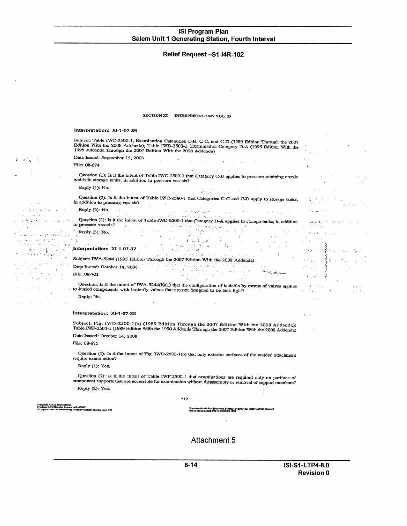
,.':
: ,". ":.,- . ~'-' .
.. .. ~:. ';,"'. ,:'" .. -: '~"."
:,' .. ,:.' :'''i
" _ ...... : .. ' ,.: .... . " .' .
! ~:
. :
lSI Program Plan Salem Unit 1 Generating Station, Fourth Interval
Relief Request -S1-14R-102
Interpretation: XI-1-07-36
SUbject! Tabl .. IWC-2500-1, ExlUllination ClfIegorles CoB, CoCo and CoD (1989 Edition Through the 2007 Edition W1th the 2008 Addenda); Table lWD-2500-1, Exominati."on Categoty D-A (1995 Edition With the 1995 Addenda Througb the '2JXI1 Edition With the 2008 Addaods) Date 1s8u""': September IS, 2008 File: 08-674
Question (1): Is it the Intent of Table IWC-:asOO"l that Category CoB IIj;JpHes to preS&Ul-""''etaining Ilome _Ids in atonlgco tanks, in addition to presSU1'll VBS8e1.s?
Reply (1): No.
Question (2); Is it the intent of Table IWC-2500-1 tba.t Categories C-C and CoD apply to "toxase tanks. . in a.ddition to pre$StJr!'! VO;'SII.eI.s?
Reply (2): No. . . .' '.:' , ..... ....... ,.: ".
~ (3): Is it the intent of Table IWD-:l500. 1 that. C_gory D.-A applies to !ltorage tanks; :In addition to 'pressure vesse1Jl?· .. : .. c'.' .. ,",' :Reply (3): Ne. '. ,'\ . :., "
i : ... ! _.~
,Int..,ri:>retation: XI-1·Q7-37 .•••• ', ,!.
oJ'
.. :;. -.' ., Subj~t: IWA-S244 (1995 Edition Through the 2007·'Bcl:ltion.'\Y'i1h the 2008 Addeoda) i?at,e 1ssued: Ootob .... 14. 2008 File: 08-701
I ••. \ .,',' ;,
j:
' ..
-~- ;'.
'I ':.:
Quastian: )if it the intent of' IW A-5244(b)(1) that the cooll,guration of isolable by meaDS of valve ... applies " . " to ·burled componeurs with buttmfly valv",( that are nOt desigued to be'leak tight? .
Reply: No.
intarpreta'tion: Xr-1~7-38
Subject: Pig. IWD.2500-1(b) (1989 Edition ThrOllgh the 2007 EditioD With tho 2008 Addenda): Table lWP-2500-1 (1989 Edition With the 19!1O Addenda Through the 2007 Edltlon With the 2008 Addenda.) Date IsSUf"..d: October 14, 2008 Pile:08-67S
Question (1): Is it tbe intent of Fig. IWD-2500-1(b) that only extm:ior IILmaces of the welded attacl!ul<>nt requite examination?
R.eply (1): Yes.
Question (2.): Is it the mte.nt of Table IWF-2500-1 that examinations are ~'eCluired onlY on portiOJlll of component supports that OIl'<> accessible:l'or examination wIthout disassembly or removal of 8TPcm memb<>rs?
Reply (2): Yell.
512
Attachment 5
8-14 ISI-S1-LTP4-8.0 Revision 0
" ...
ISI Program Plan Salem Unit 1 Generating Station, Fourth Interval
Relief Request –S1-I4R-102
8-15 ISI-S1-LTP4-8.0 Revision 0
PSEG Drawing 219563 (Supplied with original request to NRC)
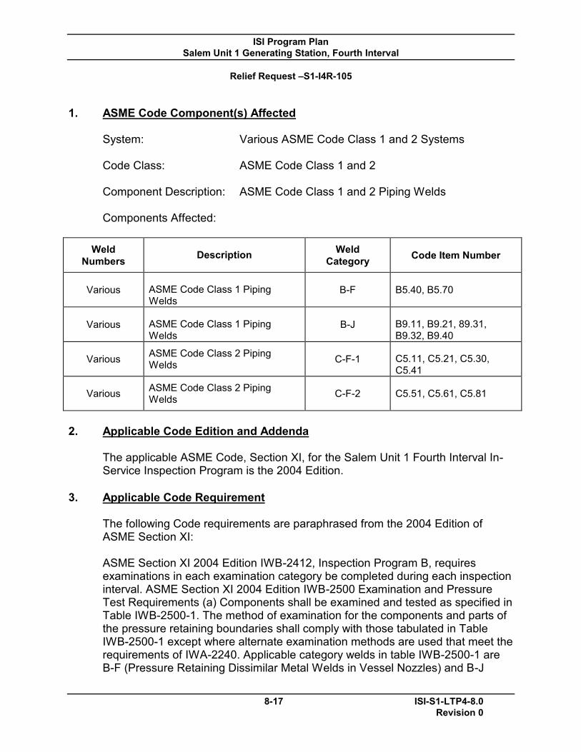
ISI Program Plan Salem Unit 1 Generating Station, Fourth Interval
Relief Request –S1-I4R-105
8-17 ISI-S1-LTP4-8.0 Revision 0
1. ASME Code Component(s) Affected
System: Various ASME Code Class 1 and 2 Systems Code Class: ASME Code Class 1 and 2 Component Description: ASME Code Class 1 and 2 Piping Welds Components Affected:
Weld Numbers Description Weld
Category Code Item Number
Various ASME Code Class 1 Piping Welds
B-F B5.40, B5.70
Various ASME Code Class 1 Piping Welds
B-J B9.11, B9.21, 89.31, B9.32, B9.40
Various ASME Code Class 2 Piping Welds C-F-1 C5.11, C5.21, C5.30,
C5.41
Various ASME Code Class 2 Piping Welds C-F-2 C5.51, C5.61, C5.81
2. Applicable Code Edition and Addenda
The applicable ASME Code, Section XI, for the Salem Unit 1 Fourth Interval In-Service Inspection Program is the 2004 Edition.
3. Applicable Code Requirement
The following Code requirements are paraphrased from the 2004 Edition of ASME Section XI: ASME Section XI 2004 Edition IWB-2412, Inspection Program B, requires examinations in each examination category be completed during each inspection interval. ASME Section XI 2004 Edition IWB-2500 Examination and Pressure Test Requirements (a) Components shall be examined and tested as specified in Table IWB-2500-1. The method of examination for the components and parts of the pressure retaining boundaries shall comply with those tabulated in Table IWB-2500-1 except where alternate examination methods are used that meet the requirements of IWA-2240. Applicable category welds in table IWB-2500-1 are B-F (Pressure Retaining Dissimilar Metal Welds in Vessel Nozzles) and B-J

ISI Program Plan Salem Unit 1 Generating Station, Fourth Interval
Relief Request –S1-I4R-105
8-18 ISI-S1-LTP4-8.0 Revision 0
(Pressure Retaining Welds in Piping). 100% of Category B-F welds and 25% of Category B-J welds for the ASME Code, Class 1, nonexempt piping shall be selected for volumetric and/or surface examination based on existing stress analyses and cumulative usage factors.
ASME Section XI 2004 Edition IWC-2412, Inspection Program B, requires examinations in each examination category be completed during each inspection interval in accordance with Table IWC-2412-1. Applicable category welds in table IWC-2500-1 are C-F-1 (Pressure Retaining Welds in Austenitic Stainless Steel or High Alloy Piping) and C-F-2 (Pressure Retaining Welds in Carbon or Low Alloy Steel Piping). For Category C-F-1 welds in Class 2 piping, the welds selected for examination shall include 7.5%, but not less than 28 welds, of all dissimilar metal, austenitic stainless steel or high alloy welds not exempted by IWC-1220. (Some welds not exempted by IWC1220 are not required to be nondestructively examined per Examination Category C-F-1. These welds, however, shall be included in the total weld count to which the 7.5% sampling rate is applied.) The examinations shall be distributed as follows:
(a) the examinations shall be distributed among the Class 2 systems
prorated, to the degree practicable, on the number of nonexempt dissimilar metal, austenitic stainless steel, or high alloy welds in each system (i.e., if a system contains 30% of the nonexempt welds, then 30% of the nondestructive examinations required by Examination Category C-F-1 should be performed on that system);
(b) within a system, the examinations shall be distributed among terminal
ends, dissimilar metal welds, and structural discontinuities prorated, to the degree practicable, on the number of nonexempt terminal ends, dissimilar metal welds, and structural discontinuities in that system; and
(c) within each system, examinations shall be distributed between line sizes
prorated to the degree practicable.
For Category C-F-2 welds in Class 2 piping the welds selected for examination shall include 7.5%, but not less than 28 welds, of all carbon and low alloy steel welds not exempted by IWC-1220. (Some welds not exempted by IWC-1220 are not required to be nondestructively examined per Examination Category C-F-2. These welds, however, shall be included in the total weld count to which the 7.5% sampling rate is applied). The examinations shall be distributed as follows:
(a) the examinations shall be distributed among the Class 2 systems prorated, to the degree practicable, on the number of nonexempt carbon and low alloy steel welds in each system (Le., if a system contains 30% of
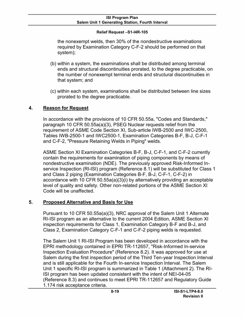
ISI Program Plan Salem Unit 1 Generating Station, Fourth Interval
Relief Request –S1-I4R-105
8-19 ISI-S1-LTP4-8.0 Revision 0
the nonexempt welds, then 30% of the nondestructive examinations required by Examination Category C-F-2 should be performed on that system);
(b) within a system, the examinations shall be distributed among terminal
ends and structural discontinuities prorated, to the degree practicable, on the number of nonexempt terminal ends and structural discontinuities in that system; and
(c) within each system, examinations shall be distributed between line sizes
prorated to the degree practicable.
4. Reason for Request
In accordance with the provisions of 10 CFR 50.55a, "Codes and Standards," paragraph 10 CFR 50.55a(a)(3), PSEG Nuclear requests relief from the requirement of ASME Code Section XI, Sub-article IWB-2500 and IWC-2500, Tables IWB-2500-1 and IWC2500-1, Examination Categories B-F, B-J, C-F-1 and C-F-2, "Pressure Retaining Welds in Piping" welds. ASME Section XI Examination Categories B-F, B-J, C-F-1, and C-F-2 currently contain the requirements for examination of piping components by means of nondestructive examination (NDE). The previously approved Risk-Informed In-service Inspection (RI-lSI) program (Reference 8.1) will be substituted for Class 1 and Class 2 piping (Examination Categories B-F, B-J, C-F-1, C-F-2) in accordance with 10 CFR 50.55a(a)(3)(i) by alternatively providing an acceptable level of quality and safety. Other non-related portions of the ASME Section XI Code will be unaffected.
5. Proposed Alternative and Basis for Use
Pursuant to 10 CFR 50.55a(a)(3), NRC approval of the Salem Unit 1 Alternate RI-ISI program as an alternative to the current 2004 Edition, ASME Section XI inspection requirements for Class 1, Examination Category B-F and B-J, and Class 2, Examination Category C-F-1 and C-F-2 piping welds is requested. The Salem Unit 1 RI-ISI Program has been developed in accordance with the EPRI methodology contained in EPRI TR-112657, "Risk-Informed In-service Inspection Evaluation Procedure" (Reference 8.2). It was approved for use at Salem during the first inspection period of the Third Ten-year Inspection Interval and is still applicable for the Fourth In-service Inspection Interval. The Salem Unit 1 specific RI-ISI program is summarized in Table 1 (Attachment 2). The RI-ISI program has been updated consistent with the intent of NEI-04-05 (Reference 8.3) and continues to meet EPRI TR-112657 and Regulatory Guide 1.174 risk acceptance criteria.
ISI Program Plan Salem Unit 1 Generating Station, Fourth Interval
Relief Request –S1-I4R-105
8-20 ISI-S1-LTP4-8.0 Revision 0
PSEG will continue to implement the Risk-Informed Inservice Inspection Program in accordance with ASME Code Case N-578-1, "Risk-Informed Requirements for Class 1, 2, and 3 Piping, Method B, Section XI, Division 1." The ultrasonic examination volume to be used based on degradation mechanism and component configuration will be the examination figures specified in Section 4 of EPRI TR-112657. The ultrasonic examination procedures, equipment, and personnel used to detect and size flaws in piping welds will be qualified by performance demonstration in accordance with ASME Section XI Appendix VIII, "Performance Demonstration for Ultrasonic Examination Systems." The volumetric scanning will be in both the axial and circumferential directions to detect flaws in these orientations. As part of the RI-ISI living program update, the delta risk assessment was re-evaluated and was determined to continue to meet the delta risk acceptance criteria of EPRI TR-112657. This update is based on the most recent Salem PRA, which has been peer reviewed to Regulatory Guide 1.200, Rev 1 and updated accordingly. The PRA has been determined to be adequate for this application as described in Appendix A.
Pursuant to 10CFR50.55a(a)(3)(i), relief is requested on the basis that the proposed alternative to continue using a Risk-Informed Inservice Inspection Program would provide an acceptable level of quality and safety.
6. Duration of Proposed Alternative Relief is requested for the Fourth Ten-Year Inspection Interval of the Salem Unit 1 Inservice Inspection Program, currently scheduled to begin on May 20, 2011 and end May 20,2021.
7. Precedent
The NRC previously approved the Salem Unit 1 Alternate Risk-Informed In-service Inspection Program in Reference 8.1.
Salem considers both the plant and industry operating experience and updates the RIlSI program during the re-evaluation process following each inspection period per our commitment in section 4 of our original relief request (Reference 8.5).
8. Reference
8.1 USNRG Letter dated October 1, 2003, "Salem Nuclear Generating Station, Unit Nos. 1 and 2-Risk-Informed Inservice Inspection Program" (TAG Nos. MB7537 and MB7538) (ML032390034)

ISI Program Plan Salem Unit 1 Generating Station, Fourth Interval
Relief Request –S1-I4R-105
8-21 ISI-S1-LTP4-8.0 Revision 0
8.2 EPRI TR-112657, Electric Power Research Institute Report for
Alternative Requirements of Risk-Informed In-service Inspection Evaluation Procedure, EPRI, Polo Alto, CA: 1999, Rev B-A.
8.3 NEI-04-05, "Living Program Guidance to Maintain Risk-Informed In-
service Inspection Programs for Nuclear Plant Piping Systems", dated April 2004.
8.4 Request for Additiqnal Information Related to Byron Station, Units 1 and
2, Request for relief 13R-02, TAG Nos. MD3855 and MD3856, dated August 8, 2007. (ML072140023)
8.5 PSEG Letter dated January 21, 2003, "Request for Authorization to use a
RiskInformed Inservice Inspection Alternative to the ASME Boiler And Pressure Vessel Code Section XI Requirements for Class 1 and 2 Piping Salem Generating Station Unit Nos. 1 and 2" Docket Nos. 50-272 and 50-311. (ML030300116)
8.6 PSEG Letter dated July 1, 2003, "Response to NRC Request for
Additional Information Regarding Risk-Informed Inservice Inspection Submittal Salem Generating Station Unit Nos. 1 and 2" Docket Nos. 50-272 and 50-311. (ML031950120)

ISI Program Plan Salem Unit 1 Generating Station, Fourth Interval
Relief Request –S1-I4R-105
8-22 ISI-S1-LTP4-8.0 Revision 0
Attachment 2 Table 1: Inspection Location Selection Comparison ASME Section XI Code and EPRI
TR-112657 by Risk Category
System*
Risk Group Consequence Category
Failure Potential Section XI
Category
1st Approved RI-ISI Interval
Proposed RI-ISI Interval
Category Rank Degradation Mechanism
Rank Weld Count
RI-ISI Other Weld Count
RI-ISI Other
AF 5 Medium Medium TT Medium C-F-2 31 4 27 (a) 3 CS 2 High High ECSCC Medium C-F-1 5 2 3 (b) 1 CS 4 Medium High None Low C-F-1 101 11 101 11 CS 5 Medium Medium IGSCC, ECSCC Medium C-F-1 2 1 2 1 CS 6 Low Medium None Low C-F·1 52 0 50 (c) 0 CS 7 Low Low None Low C-F-1 18 0 18 0
CVC 2 High High TASCS, TT Medium B-J 5 1 5 1 CVC 2 High High TT Medium B-J 2 1 2 1 CVC 4 Medium High None Low B-J, C-F-1 102 11 102 11 CVC 5 Medium Medium TT Medium B-J 27 3 27 3 CVC 5 Medium Medium ECSCC Medium C-F-1 12 1 8 (d) 1 CVC 6 Low Medium None Low B-J, C·F-1 336 0 299 (e) 0 CVC 7 Low Low None Low B-J 0 0 34 (f) 0 MS 6 Low Medium None Low C-F-2 235 0 235 0
RC 2 High High TASCS, TT, PWSCC Medium B-F 1 1 0(g) 0
RC 2 High High TASCS, TT Medium B-J 14 2 18 (h) 5 RC 2 High High TT, PWSCC Medium B-F 1 1 0(g) 0 RC 2 High High TT Medium B-J 3 1 11 (i) 3 RC 2 High High PWSCC Medium B-F 12 5 0(g) 0 RC 4 Medium High None Low B-F, B-J 208 25 216 (j) 29 RC 6 Low Medium None Low B-J 9 0 0(k) 0 RC 6 Low Low IGSCC Medium C-F-1 6 0 6 0 RC 6 Low Low ECSCC Medium C-F·1 1 0 1 0 RC 7 Low Low None Low B-J, C-F-1 85 0 95 (l) 0
RHR 2 High High TASCS Medium B·J, C·F-1 7 2 7 2
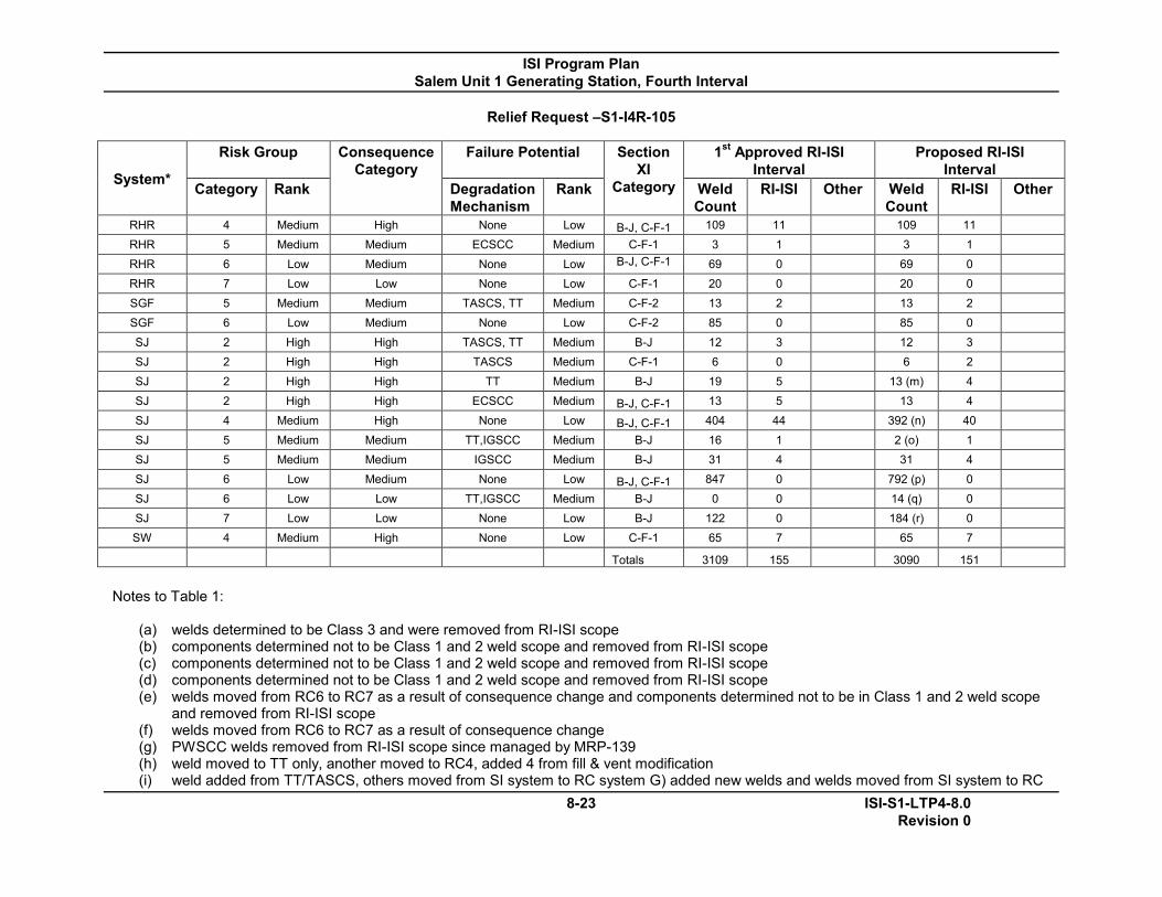
ISI Program Plan Salem Unit 1 Generating Station, Fourth Interval
Relief Request –S1-I4R-105
8-23 ISI-S1-LTP4-8.0 Revision 0
System*
Risk Group Consequence Category
Failure Potential Section XI
Category
1st Approved RI-ISI Interval
Proposed RI-ISI Interval
Category Rank Degradation Mechanism
Rank Weld Count
RI-ISI Other Weld Count
RI-ISI Other
RHR 4 Medium High None Low B-J, C-F-1 109 11 109 11 RHR 5 Medium Medium ECSCC Medium C-F-1 3 1 3 1 RHR 6 Low Medium None Low B-J, C-F-1 69 0 69 0 RHR 7 Low Low None Low C-F-1 20 0 20 0 SGF 5 Medium Medium TASCS, TT Medium C-F-2 13 2 13 2 SGF 6 Low Medium None Low C-F-2 85 0 85 0 SJ 2 High High TASCS, TT Medium B-J 12 3 12 3 SJ 2 High High TASCS Medium C-F-1 6 0 6 2 SJ 2 High High TT Medium B-J 19 5 13 (m) 4 SJ 2 High High ECSCC Medium B-J, C-F-1 13 5 13 4 SJ 4 Medium High None Low B-J, C-F-1 404 44 392 (n) 40 SJ 5 Medium Medium TT,IGSCC Medium B-J 16 1 2 (o) 1 SJ 5 Medium Medium IGSCC Medium B-J 31 4 31 4 SJ 6 Low Medium None Low B-J, C-F-1 847 0 792 (p) 0 SJ 6 Low Low TT,IGSCC Medium B-J 0 0 14 (q) 0 SJ 7 Low Low None Low B-J 122 0 184 (r) 0 SW 4 Medium High None Low C-F-1 65 7 65 7
Totals 3109 155 3090 151
Notes to Table 1:
(a) welds determined to be Class 3 and were removed from RI-ISI scope (b) components determined not to be Class 1 and 2 weld scope and removed from RI-ISI scope (c) components determined not to be Class 1 and 2 weld scope and removed from RI-ISI scope (d) components determined not to be Class 1 and 2 weld scope and removed from RI-ISI scope (e) welds moved from RC6 to RC7 as a result of consequence change and components determined not to be in Class 1 and 2 weld scope
and removed from RI-ISI scope (f) welds moved from RC6 to RC7 as a result of consequence change (g) PWSCC welds removed from RI-ISI scope since managed by MRP-139 (h) weld moved to TT only, another moved to RC4, added 4 from fill & vent modification (i) weld added from TT/TASCS, others moved from SI system to RC system G) added new welds and welds moved from SI system to RC

ISI Program Plan Salem Unit 1 Generating Station, Fourth Interval
Relief Request –S1-I4R-105
8-24 ISI-S1-LTP4-8.0 Revision 0
system (j) added new welds and welds moved from SI system to RC system (k) welds moved from RC6 to RC7 as result of consequence change (I) welds moved from RC6 to RC7 as a result of consequence change, other welds moved from RC6 to RC7 (were incorrectly assigned)
and another weld deleted as not in scope (m) welds moved from SI to RC system (n) welds moved from RC4 to RC6 as result of consequence change and other welds moved from SI system to RC system (o) RC5 welds moved to RC6 as a result of consequence change (p) welds moved from RC6 to RC7, others moved from RC7 to RC6, and some moved from RC4 to RC6 due to consequence changes (q) RC5 welds moved to RC6 as result of consequence change (r) welds moved from RC6 to RC7, others moved from RC7 to RC6 due to consequence change
*Systems defined: AF –Auxiliary Feedwater System CS –Containment Spray System CVC –Chemical and Volume Control System MS –Main Steam System RC –Reactor Coolant System RHR –Residual Heat Removal System SGF –Steam Generator Feedwater system SJ –Safety Injection System SW –Service Water System

ISI Program Plan Salem Unit 1 Generating Station, Fourth Interval
Relief Request –S1-I4R-105
8-25 ISI-S1-LTP4-8.0 Revision 0
Attachment 3
Salem PRA Summary The Salem PRA has been updated several times to maintain current with the plant design and operation and to support peer review. Revision 3 to the model was released as a draft in November 2001 in preparation for the Westinghouse Owners Group (WOG) peer review. Documentation for Revision 3 was finalized in June 2002. This is the version of the model that was used for the original RI-ISI submittal. More recently, the PWR Owners Group conducted a peer review of Regulatory Guide 1.200, Rev 1, "Approach for Determining the Technical Adequacy of Probabilistic Risk Assessment Results for Risk-Informed Activities," in November of 2008. A final report of that peer review was issued in March of 2010. PSEG Nuclear has made changes to the model post peer review and maintains the attached Table A1 of "Identified Gaps to Capability Category II of the ASME Standard" which discusses significance of the gap and is assessed for each application. The latest PRA model used for this evaluation is Revision 4.3, which is adequate to support this application based on a review of the gaps and their significance. The original RI-ISI evaluation concluded external events are not likely to impact the consequence ranking. This position is further supported by Section 2 of EPRI Report 1021467, "Nondestructive Evaluation: Probabilistic Risk Assessment Technical Adequacy Guidance for Risk-Informed In-Service Inspection Programs" which concludes that quantification of these events will not change the conclusions derived from the RI-lSI process. As a result, there is no need to further consider these events.

ISI Program Plan Salem Unit 1 Generating Station, Fourth Interval
Relief Request –S1-I4R-105
8-26 ISI-S1-LTP4-8.0 Revision 0
Table A1: Identified Gaps to Capability Category II of the ASME PRA Standard
Finding Finding Description Applicable
Supporting Requirements
Resolution
IE-A1-01 A loss of an AC bus may not result in a reactor trip, but may result in a forced shutdown due to technical specifications. If the lost bus happens to be the operating bus for equipment, systems will be challenged. Loss of an AC bus is generally modeled in most PRAs. This F&O is characterized as a finding based on the lack of sufficient documentation to allow verification of SR. Include events for loss of 4Kv bus if they require a forced shutdown consistent with most industry PRAs.
IE-A1 Minimal impact, referenced event is bounded by the modeled reactor trip initiator. Initiator impact is a qualitative consideration.
IE-A3-01 Historical events appear to lead to somewhat more complex situations than the assigned grouping would indicate. The plant-specific history indicates that on 12/31/01 an event occurred resulting in SI. The categorization of initiating events does not account for this or the case of ESFAS actuation. This F&O is characterized as a finding based on the lack of sufficient documentation to allow verification of SR. Consider re-categorizing this event as an ESF actuation (QR9).
IE-A3 Response: Table 3-2 indicates this was binned as a trip with loss of feedwater, consistent with the classification scheme employed for Salem (Spurious SI = Tp). Negligible impact on technical adequacy of the PRA model.

ISI Program Plan Salem Unit 1 Generating Station, Fourth Interval
Relief Request –S1-I4R-105
8-27 ISI-S1-LTP4-8.0 Revision 0
Finding Finding Description Applicable
Supporting Requirements
Resolution
IE-A3a-01 Although sited as an input source, there appears to be no documentation supporting a comparison of initiating events with regard to plants of similar design. The documentation indicates that "past probabilistic risk assessments" were used for source and experience. However, there is not documentation of such a comparison. It also does not identify that any examination was made for Salem-like designs. A comparison to similar designs can potentially identify those design-specific events than may have unique consequences which may not be defined in more generic sources. It also provides an industry basis for selection. This F&O is characterized as a finding based on the lack of sufficient documentation to allow verification of SR. Utilize available industry summary documentation to define generally appropriate initiating event list for specific design.
IE-A3a Comparisons were made to industry data and to other plants. This is judged to be a documentation consideration only and does not affect the technical adequacy of the PRA model.
IE-A4-01 The requirement is to address each system, including support systems to assess potential for initiating events. The analysis only addresses support systems and does not address the impact of other operating systems with regard to events resulting in a plant upset and subsequent trip signal. For charging this has the potential to impact both the initiator and response models such that consequential failures could be possible. This F&O is characterizing as a finding based on the lack of sufficient documentation to allow verification of SR. Add evaluations for frontline operating systems that in particular are part of the PRA response model.
IE-A4 Loss of charging not included based on screening criterion, must cause automatic or manual trip AND frontline systems are significantly affected. No significant impact on frontline systems expected. This is judged to be a documentation consideration only and does not affect the technical adequacy of the PRA model.

ISI Program Plan Salem Unit 1 Generating Station, Fourth Interval
Relief Request –S1-I4R-105
8-28 ISI-S1-LTP4-8.0 Revision 0
Finding Finding Description Applicable
Supporting Requirements
Resolution
IE-A5-01 SA PRA Initiating Events Notebook, SA-PRA-001, Revision 0, Section 2.1.2 describes the review of Salem Generating Station Experience and Trip Review. No mention is made of consideration of events that occurred at conditions other than at-power operation. Also, events resulting in controlled shutdown were excluded on the basis that they present only mild challenges rather than being determined to be not applicable to at-power operation. Failure to consider non-power events and controlled shutdown events could result in exclusion of valid initiating events. Provide an explicit discussion of the review of non-power events. Improve the justification for exclusion of controlled shutdown events to address applicability to at-power operation or to provide a quantitative justification for exclusion.
IE-A5 Other than at-power events were evaluated. This is judged to be a documentation consideration only and does not affect the technical adequacy of the PRA model.
IE-A6-01 SA PRA Initiating Events Notebook, SA-PRA-001, Revision 0, Section 2.1.2 does not indicate that plant operations, maintenance, engineering, and safety analysis personnel were interviewed or included in the review process for the initiating events notebook to determine if potential initiating events have been overlooked. Documentation was not available to show that the Category II/III requirement was satisfied. The initiating event analysis should document a reasonably complete identification of initiating events. Document the required interviews.
IE-A6 This is judged to be a documentation consideration only and does not affect the technical adequacy of the PRA model.

ISI Program Plan Salem Unit 1 Generating Station, Fourth Interval
Relief Request –S1-I4R-105
8-29 ISI-S1-LTP4-8.0 Revision 0
Finding Finding Description Applicable
Supporting Requirements
Resolution
IE-A7-01 SA PRA Initiating Events Notebook, SA-PRA-001, Revision 0, Section 2.1.2 does not indicate that a review of plant-specific or industry operating experience was performed for the purpose of identifying initiating event precursors. Failure to consider precursor events and controlled shutdown events could result in exclusion of valid initiating events. The model owner stated that precursors were considered during the review of plant operating experience. However, because this is not documented, the SR cannot be considered met. This should be explicitly stated in the Initiating Events Notebook.
IE-A7 Plant and industry operating experience was reviewed. This is judged to be a documentation consideration only and does not affect the technical adequacy of the PRA model.
IE-B3-01 Initiating events are not grouped with less severe events without assuming the worst potential effects. For example, the potential for a spurious SI actuation is grouped in the general transient category with events such as reactor trip and considered to be no worse than the reactor trip. However, unmitigated spurious SI events can challenge a PORV resulting in a consequential LOCA. Spurious SI events should not be grouped with general reactor trips. Also, the loss of AC power bus (F) is said to result in a degraded loss of condensate/feedwater performance. However, it is placed in the PCS available category. This presents a problem when developing the conditional failure PCS in response to the event. This F&O is characterized as a finding based on the lack of sufficient documentation to allow verification of SR. Separate out events on basis of unique impacts to the response sequence.
IE-B3, AS-A5
Initiating events should be grouped reasonably, as PRA should be realistic and not conservative. Spurious SI will generally be recovered and the event will be a transient. If SI is not reset prior to PORV operation, what results is a transient with improved reliability of feed-and-bleed cooling (already initiated). SI can still be reset and PORV closed. If difficulty is experienced in closing PORV, block valve can be closed. Regarding the loss of AC bus, this does not result in even a trip so it would be quite conservative to bin such events as trips with loss of PCS. Minimal impact on the ability to assess significance of proposed application.

ISI Program Plan Salem Unit 1 Generating Station, Fourth Interval
Relief Request –S1-I4R-105
8-30 ISI-S1-LTP4-8.0 Revision 0
Finding
Finding Description
Applicable Supporting
Requirements
Resolution
IE-C1b-01 The loss of SW initiating event fault tree S1R4.Caf (gate IE-TSW) was reviewed and the logic appears to capture the appropriate combinations of equipment failures that contribute to the initiator. However, the documentation of the development of the initiator fault trees appears to be lacking. Section 3.3 of the Salem SA--PRA-001, Revision 0 notebook does not provide much detail of how the initiators modeled 'as-fault' trees are developed. It refers to the system model notebook. For the loss of SW initiator, the SW model notebook SA-PRA-005.13, Revision 0 was reviewed and there was no discussion of the development of the loss of SW initiator fault tree. For the loss of CC initiator fault tree, Section 4.2 of notebook SA-PRA-005.12, Revision 0 provides a good description of how that initiator fault tree is developed. This F&O is characterized as a finding based on the lack of sufficient documentation to allow verification of SR IE-C1b. Document how the loss of SW initiating event fault tree is developed. Likewise for other system initiators, as needed. Include a discussion of the recoveries credited in the initiator. This should also be done for the other initiators that are fault trees.
IE-C1b, IE-C6 This is judged to be a documentation consideration only and does not affect the technical adequacy of the PRA model.
IE-C3-01 The initiators that are fault trees, such as loss of SW and loss of CC, the initiator frequency is not based on reactor year. For example, under gate IE-TSW, basic event SWS-PIP-RP-TBHDR has a mission time of 8760 hours. This F&O is characterized as a finding because it does not meet the SR. Use reactor year when quantifying the initiator frequencies.
IE-C3 This is a minor conservative modeling issue and would not affect the ability to assess the impact of an application.

ISI Program Plan Salem Unit 1 Generating Station, Fourth Interval
Relief Request –S1-I4R-105
8-31 ISI-S1-LTP4-8.0 Revision 0
Finding
Finding Description
Applicable Supporting
Requirements
Resolution
AS-A7-01 Accident Sequences and Event Tree Development Notebook, SA--PRA-002, Revision 0 delineates the possible accident sequences for each modeled initiating event. However, some sequences are not explicitly modeled in the single-top fault tree (e.g., TT sequences S04 and S05 are combined into a single fault tree gate). No documentation was found to describe the basis of these combinations. Subsuming non-minimal sequences in the single-top fault tree model could result in loss of risk insights or masking of importance in non-standard configurations. Provide a description of the process used to combine non-minimal sequences with their bounding equivalent sequence in both the Accident Sequences and Event Tree Notebook or in the Quantification Notebook. Discuss how it is ensured that risk insights are not impacted by the subsuming of sequences. Provide a more complete basis for not modeling sequences judged to have "very low frequencies" such that a reviewer can evaluate the basis for the exclusion.
AS-A7 Sequences TTS04 and TTS05 differ only in whether containment is isolated, which is of concern only in level 2, not for CDF. Level 2 analysis does address containment status. Not excluded based on very low frequency. This is judged to be a documentation consideration only and does not affect the technical adequacy of the PRA model.
AS-A7-02 The VS ISLOCA sequence with no piping failure is assumed to be terminated with operator isolation of the suction path using the pump suction isolation MOVs. However, isolation cannot be accomplished until primary pressure is reduced. The potential for flooding of adjacent areas by water lost through the RHR pump seals and/or RHR heat exchangers prior to isolation does not appear to have been evaluated. Flooding of adjacent areas could impact additional equipment affecting the ability to achieve a safe, stable condition. Evaluate the potential volume of water which can be released prior to isolation of the VS sequence with no piping failure to determine if additional mitigation equipment could be affected.
AS-A7 Inventory loss from the postulated ISLOCA would not be expected to flood more than the lower levels of the auxiliary building. RH-4 valves which could be used for isolation are located a floor above the postulated break. Flooding analysis addresses plant response and demonstrates that the plant can be safely shut down without the potentially affected components. This is judged to be a documentation consideration only and does not affect the technical adequacy of the PRA model.
Finding
Finding Description
Applicable Supporting
Resolution

ISI Program Plan Salem Unit 1 Generating Station, Fourth Interval
Relief Request –S1-I4R-105
8-32 ISI-S1-LTP4-8.0 Revision 0
Requirements AS-A8-01 Accident Sequences and Event Tree Development Notebook, SA-
PRA-002, Revision 0 and the associated CAFTA event trees define the end state of each sequence as success or core damage. However, the SBO sequences S08, S11, S14, and S17 are assumed to be successful based on offsite power recovery. Operator action to restore mitigating systems after power recovery is not addressed. In addition, given the fact that power recovery is only credible out to 4 hours, 20 hours of mitigating system operation and the potential failures of that equipment over a significant portion of the 24 hour mission time is not being addressed. This failure to address recovery of mitigating systems following power recovery does not ensure a safe, stable end state has been reached for some SBO sequences. There is also concern that the application of offsite power recovery is included twice in the modeling of the SBO event. Recovery is credited in the application of a diesel mission time of 6 hours and again through the application of offsite power recovery top event RBU. Recovery of offsite power does not guarantee restoration of mitigating systems needed to establish a safe stable condition in the plant. In some plant models, operator action to restore required mitigating systems following power recovery has been shown to be significant. In addition, mitigating system operation over a significant portion of the 24 mission time is not being addressed. Extend the event tree models to address restoration and operation of required safety functions following offsite power recovery. Potential events to include are decay heat removal and primary inventory makeup.
AS-A8, AS-B6 Mission times vice recovery of offsite power are addressed in current PRA model. Documentation issue.

ISI Program Plan Salem Unit 1 Generating Station, Fourth Interval
Relief Request –S1-I4R-105
8-33 ISI-S1-LTP4-8.0 Revision 0
Finding
Finding Description
Applicable Supporting
Requirements
Resolution
AS-A10-01
Systems and operator actions required to meet each key safety function are discussed in general terms in the Accident Sequences and Event Tree Development Notebook, SA-PRA-002, Revision 0 Sections 3 through 9. Operator actions and diverse systems to satisfy top events are included in the fault tree but are grouped under common top events in the accident sequence model (e.g., core decay heat removal includes AFS, operator action to depressurize, and condensate under a common top event). However, the modeling of offsite power recovery in the SBO event tree does not explicitly model the differences in recovery times or plant response associated with different RCP seal leakage rates. Instead, a single lumped recovery event is modeled. The lumping of RCP seal leakage rate with offsite power recovery under the RBU top event does not provide sufficient detail to determine differences in requirements for mitigation systems and operator responses. For example, RCP seal leakage of 21 gpm per pump may proceed like a general transient and only require secondary side cooling whereas larger seal leakage rates may also require primary makeup for success. Provide explicit event tree branches for each RCP seal leakage rate the event timing and mitigation requirements for different leakage rates can be shown to be the same. This will ensure that significant differences in mitigation requirements and event timing are captured.
Varying seal leak rates are now explicitly addressed.

ISI Program Plan Salem Unit 1 Generating Station, Fourth Interval
Relief Request –S1-I4R-105
8-34 ISI-S1-LTP4-8.0 Revision 0
Finding
Finding Description
Applicable Supporting
Requirements
Resolution
AS-C2-01 Documentation does not clearly address the procedural guidance, operator actions and interfaces of the plant event trees with plant damage states. The current documentation does not include sufficient detail to allow correlation of operator actions required to mitigate the accident sequences to the HRA or the interface between the accident sequences and plant damage states carried forward to the Level 2 analysis. Expand the event trees to include important operator actions as separate top events or provide a table which describes operator actions included under each existing top event. Provide a description of the procedural guidance used in mitigation of each accident sequence or group of accident sequences. Document the interfaces between the event tree end points and piant damage states in the Accident Sequence notebook or through a specific reference to the appropriate section of the Level 2 notebook.
Operator actions and related procedural guidance are discussed in detail in HRA notebook. Plant event trees, success / failure paths are discussed in accident sequence and success criteria notebooks. Level 2 notebook describes interfaces. This information has been provided in the accident sequence, success criteria and L2 notebooks.
SC-A1-01 The ASME standard defines core damage as "uncovery and heatup of the reactor core to the point at which prolonged oxidation and severe fuel damage involving a large section of the core is anticipated." In the Salem PRA Success Criteria Notebook, SA-PRA-003, a "big picture" definition as described in the ASME PRA standard appears to missing. In the Salem PRA, core damage is defined as maintaining core temperature below 1200 degrees F which deals with heatup but not uncovery. The big picture definition of core damage is incomplete in that it defines core heatup but not uncovery. Include core uncovery in the definition of core damage.
Documentation clarified regarding core damage.

ISI Program Plan Salem Unit 1 Generating Station, Fourth Interval
Relief Request –S1-I4R-105
8-35 ISI-S1-LTP4-8.0 Revision 0
Finding
Finding Description
Applicable Supporting
Requirements
Resolution
SC-A2-01 In the Salem PRA core cooling was defined as successful if core exit temperatures do not exceed 1200 degrees F. This represents the temperature below which no core damage is expected to occur and the core exit thermocouple temperature at which the operators transfer to severe accident guidelines. The 1200 degrees F core temperature success criteria were interpreted to be the core hottest node temperature (TCRHOT) in MAAP. However, in the T/H notebook a peak cladding temperature of 1800 degrees F was referenced. The MAAP code used 1800 degrees as TCRHOT. Also, there is no mention of core collapsed liquid level. The temperature defined for core damage in the success criteria notebook was not the temperature used for TCRHOT in the MAAP code. Reconcile the definition of core damage between the T/H calculations and the success criteria notebook.
Documentation clarified regarding core damage
SC-B4-01 MAAP Thermal-Hydraulic Calculations Notebook (SA-PRA-007, Revision 1) Sections 1.2 and 1.3 provide a discussion of the codes available and the advantages associated with using MAAP, respectively. However, MAAP is used in establishing large LOCA success criteria, although the code is not suitable for analysis of this plant upset. A discussion of code limitations needs to be documented. Use of a non-applicable code could result in incorrect success criteria. Base the success criteria for large LOCA on an appropriate T/H code. Provide a general discussion of known T/H code limitations.
Documentation updated.

ISI Program Plan Salem Unit 1 Generating Station, Fourth Interval
Relief Request –S1-I4R-105
8-36 ISI-S1-LTP4-8.0 Revision 0
Finding
Finding Description
Applicable Supporting
Requirements
Resolution
SC-B5-01 A check of the reasonableness and acceptability of the success criteria results is not documented. Comparing success criteria results with those of similar plants or performed using other plant-specific codes provides greater assurance that the results are correct. Document a check of the reasonableness and acceptability of the success criteria results. Supporting requirement SC-B5 provides example methods. Note that the PWROG PSA database identifies success criteria for its constituent plants and may be a helpful resource.
SC-B5 This is judged to be a documentation consideration only and does not affect the technical adequacy of the PRA model.
SC-C3-02
Sources of uncertainty are addressed in a draft evaluation using guidance from draft EPRI report, "Treatment of Parameter and Model Uncertainty for Probabilistic Risk Assessments." An appropriate characterization of uncertainty is required to support risk-informed decision making. Apply the EPRI guidance, once finalized, to identify the sources of uncertainty in the analysis.
SC-C3, AS-C3, HR-D6, HR-G9, HR-I3, DA-E3, QU-E1, QU-E3, QU-E4, QU-F4, LE-F2, LE- G4
This is judged to be a documentation consideration only and does not affect the technical adequacy of the PRA model.
SY-A4-01 System walkdown documentation not included in the system notebook documentation. A review of system notebooks and available documentation does not include system walkdown information. A draft document containing photos and documentation of insights from a system walkdown was provided to the peer review but is not finalized. Finalize the provided notebook.
SY-A4 This is judged to be a documentation consideration only and does not affect the technical adequacy of the PRA model.
SY-A6-01 Missing boundary definitions for system models. The system notebooks do not clearly define the boundaries. The training documentation is not adjusted to be specific to the PRA model. Additionally some systems, such as ac power, do not include discussion of modeled events. The diesel generator and the fuel oil transfer system are not addressed explicitly. Develop PRA specific illustrations and expand documentation to clearly describe the system boundaries to ensure that no components are double counted or missed.
SY-A6, SY-C2 This is judged to be a documentation consideration only and does not affect the technical adequacy of the PRA model.

ISI Program Plan Salem Unit 1 Generating Station, Fourth Interval
Relief Request –S1-I4R-105
8-37 ISI-S1-LTP4-8.0 Revision 0
Finding
Finding Description
Applicable Supporting
Requirements
Resolution
SY-A8-01 Review of notebooks and data notebook did not provide a source for inclusion or exclusion of failure modes based on data boundaries. No documentation of component boundaries. Expand the data discussion to provide component definitions.
SY-A8 This is judged to be a documentation consideration only and does not affect the technical adequacy of the PRA model.
SY-A10-01
Some systems do not include expected failure modes and although this may be correct, there is no documentation as to how the data boundaries encompass the expected failures. One example is the diesel generator model does not include the diesel generator day tank and instrumentation. The response to inquiries was that these components are part of the diesel skid package. This is usually separate modeling to capture miscalibrations. Define what is included within the diesel generator "box" or expand the model.
SY-A10 This is judged to be a documentation consideration only and does not affect the technical adequacy of the PRA model.
SY-A12-01
Review of system models identified some missing component failure modes. Required components are not always addressed in the model. For example, the diesel generator day tank and fuel oil check valves are not included. Additionally, restart of some components (such as dampers having to re-open for CAV) are absent in the model. Define boundaries to show incorporation of failure modes by other events or expand model.
SY-A12 Components are included in the PRA model either explicitly or as part of a super-component. This is judged to be a documentation consideration only and does not affect the technical adequacy of the PRA model.
SY-A13-01
The modeling excludes some required component failures without justification. Some failure modes listed for inclusion in the SR are not found or are excluded from the model. This includes the transfer closed/plugging failure modes for valves and the absence of some check valves and/or tanks. Justify the exclusion of any failure mode or model the failure mode.
SY-A13 This is judged to be a documentation consideration only and does not affect the technical adequacy of the PRA model.

ISI Program Plan Salem Unit 1 Generating Station, Fourth Interval
Relief Request –S1-I4R-105
8-38 ISI-S1-LTP4-8.0 Revision 0
Finding
Finding Description
Applicable Supporting
Requirements
Resolution
SY-A16-01
The SWS fault tree includes recovery via alignment of the header crosstie. HFE SWS-XHE-FO-OVER2 is used for this recovery action in all cases, even LOSP. However, the timing used in the HRA for this action is based on room heatup following a loss of CAY, not on the more restrictive timing required for recovery of cooling to a diesel following LOSP. Application of the HFE for recovery of SW via the header crosstie in the incorrect context may result in underestimating the importance of the HFE and associated equipment required for the recovery. Create a variation of the SWS-XHE-FO-OVER2 HFE accounting for differences in timing during LOSP conditions where cooling to a diesel generator is required.
SY-A16 Action can be taken from the control room and will be taken within 10 minutes or less based on responses to control room alarms, which should be adequate. Minimal impact to application.
SY-A19-01
System notebooks do not include discussions on potential adverse operating conditions that could impact operation. No documentation of any potential for loss of desired system function, e.g., excessive heat loads, excessive electrical loads, excessive humidity, etc. Add brief discussion.
SY-A19, SY-A20 This is judged to be a documentation consideration only and does not affect the technical adequacy of the PRA model.
SY-A21-01
The current type code does not provide consistent nomenclature for same failure data. The SR indicates that the nomenclature should use the same identifier for the same failure mode. The type code changes by system although the data is from the same source. For data sources from the same reference the same type code should be used. Using type codes by system may obscure the state of knowledge information.
SY-A21, QU-A2b Same data are used for different types of failures when data are lacking and a surrogate data set is required (e.g. diesel air compressors). Minimal impact to application.

ISI Program Plan Salem Unit 1 Generating Station, Fourth Interval
Relief Request –S1-I4R-105
8-39 ISI-S1-LTP4-8.0 Revision 0
Finding
Finding Description
Applicable Supporting
Requirements
Resolution
SY-B3-01 The review of the system model and documentation identified cases the selection of CCF combinations are not complete and those selected are not the most limiting. Example of incorrect usage is found for the dc chargers. Combinations of 3, 4 and 5 of six chargers are not included in current model. Additionally, CCF for two of two on same bus is modeled but cross train is not addressed (A & B, A &C, B &C) which are more significant. Review and revise as appropriate the selection of CCF combinations and model all possible combinations of CCF.
Additional battery charger CCF terms are now included.
SY-B5-01 Documentation indicated that the heated water circulating system was required. Documentation for several system notebooks (AFW, CVCS and RWST) indicated that the heated water circulating system was required to prevent freezing, but was not modeled. Model the heated water circulating system or justify the reason for not modeling.
SY-B5 This is judged to be a documentation consideration only and does not affect the technical adequacy of the PRA model.
SY-B6-01 No documentation provided related to analysis of support system requirements. There appears to be no analysis of support system requirements concurrent with their definition in the system notebooks. Perform the required engineering analysis.
Support system requirements are analyzed, modeled, documented.
SY-B11-01
Some AFW signals (SI, LOSP) are not defined and no justification for exclusion is provided. The SR states that actuation signals must be considered or justification provided. The AFW start signals are not completely modeled and justifications for exclusion are not provided. Provide justification for exclusion of the AFW signals or model these signals.
SY-B11 This is judged to be a documentation consideration only and does not affect the technical adequacy of the PRA model.
Finding
Finding Description
Applicable
Resolution

ISI Program Plan Salem Unit 1 Generating Station, Fourth Interval
Relief Request –S1-I4R-105
8-40 ISI-S1-LTP4-8.0 Revision 0
Supporting Requirements
SY-B12-01
Some run times for components do not reflect the actual required mission time. Several components reflect 8 hour run times (DG and control room fans as examples) when the required mission time is continued operation 24 hours. The design generator and turbine driven pump run time of 6 hours is not sufficient to address the total run time of 24 hours. Justify mission times or revise the mission times to the required value.
Mission times changed in current model
HR-B2-01 DO NOT screen activities that could simultaneously have an impact on multiple trains of a redundant system or diverse systems (HR-A3).
Section 4.3.3.1 of the HRA Notebook which allows screening of actions that could simultaneously have an impact on multiple trains of a redundant system or diverse systems is in violation of this. This requirement is not met. Change the documentation to reflect that the activities are being screened because they are either not in the PRA model or do not impact any success criteria. No screening performed. Documentation clarified.

ISI Program Plan Salem Unit 1 Generating Station, Fourth Interval
Relief Request –S1-I4R-105
8-41 ISI-S1-LTP4-8.0 Revision 0
Finding
Finding Description
Applicable Supporting
Requirements
Resolution
HR-C3-01 There is no documentation showing that miscalibration as a mode of failure of initiation of standby systems was considered. An example of this is that there is no HFE for miscalibration of bus undervoltage bus, RPS relays, etc. There is no documentation showing that miscalibration as a mode of failure of initiation of standby systems was considered. An example of this is that there is no HFE for miscalibration of bus undervoltage bus, RPS relays, etc. Consider analyzing the miscalibration of standby systems.
HR-C3, SY-B16 Can be considered to be modeled by common-cause failure events. No impact expected to application.
HR-F2-01 Complete the definition of the HFEs by specifying: (a) Accident sequence specific timing of cues, and time
window for successful completion (b) Accident sequence specific procedural guidance (e.g.,
AOPs, and EOPs) (c) The availability of cues and other indications for detection
and evaluation errors. (d) The complexity of the response.
(Task analysis is not required.) The accident sequence specific timing of time window for successful completion for CCS-XHE-FO-ISOLT is not based on a calculation that addresses leakage. The calculation S-CC-MDC-2111 is for loss of Service Water and does not address leakage of the Component Cooling Water System. The time window should account for leakage that would drain the CCW system and make it inoperable. This is the limiting time since the CCW system will continue to cool with the leak until the surge tank is drained. This is only one example of a timing window error. Review all HRA analysis to verify that the time window in the analysis is based on an applicable calculation. This review needs to be documented
This information is available. The cited calculations were reviewed and found to provide appropriate basis for the related operator actions. No impact to application.

ISI Program Plan Salem Unit 1 Generating Station, Fourth Interval
Relief Request –S1-I4R-105
8-42 ISI-S1-LTP4-8.0 Revision 0
Finding
Finding Description
Applicable Supporting
Requirements
Resolution
DA-A1a-01
No discussion of component boundary definition is provided in either the data or systems analysis. Boundaries for unavailability events are not established. Boundary definitions help assure that failures are attributed to the correct component and that calculated failure rates and unavailability values are appropriate. Some component boundaries are discussed in the notes to Appendix A, "Generic (Industry) Failure Data" of the Data Notebook. Note 32 states to "Assume that CCW/RHR HX failure rates apply to TDAFW Pump Bearing and governor jacket coolers", however unless the Salem TDAFW pump has unique features that require this to be modeled separately, cooling to the TDAFW pump is usually included in the component boundary to the pump. Define the component boundary for each component consistent with the failure data source. Establish boundaries for unavailability events consistent with definitions in the systems analysis.
DA-A1a, DA-C1 This is judged to be a documentation consideration only and does not affect the technical adequacy of the PRA model.
DA-A2-01 Mean values for failure rates appear in the model; however no uncertainty distributions could be found in the basic event database. Failure rates used in the model are not exact and uncertainty distributions are needed to help bound the analysis. Include data distributions in the database in the model.
Data distribution information is documented.
DA-C1-01 Generic unavailability data is used for some SSCs without demonstrating that the data is consistent with the test and maintenance philosophies for the subject plant. Generic unavailability data may not be applicable to Salem if its T&M approach is different. Review and state that any generic unavailability data used is applicable to the Salem model.
DA-C1 This is judged to be a documentation consideration only and does not affect the technical adequacy of the PRA model.

ISI Program Plan Salem Unit 1 Generating Station, Fourth Interval
Relief Request –S1-I4R-105
8-43 ISI-S1-LTP4-8.0 Revision 0
Finding
Finding Description
Applicable Supporting
Requirements
Resolution
DA-C2-01 Plant-specific data is only collected for MSPI components. The PRA procedure requires plant specific data to be collected for components with a RAW >2 or an F-V greater than 0.005. MSPI components are only a subset of the risk-significant components. Expand collection of plant-specific data to all modeled components or justify why the generic data is applicable.
DA-C2 Plant-specific data is collected and maintained by the station for components and systems such as those tracked for MSPI. The PRA was updated with this plant specific data. This is believed to be appropriate. Documentation issue.
DA-C4-01 Documentation describing the process of evaluating maintenance records for failures could not be identified. All failures must be reviewed for applicability to the PRA model. Failure rates are dependent on an accurate failure count. Document the process of evaluating maintenance records for failures, ensuring failures are reviewed for applicability to the PRA model in accordance with SR-DA-C4.
Plant data were developed from existing plant programs (e.g. MSPI, maintenance rule, etc.) which is also an acceptable approach.
DA-C5-01 Documentation describing the process for counting component failures could not be identified. Failure rates are dependent on an accurate failure count. Counting repeated failures occurring within a short interval could skew the importance of SSC. Document the process for counting component failures, consistent with SR DA-C5. The draft data procedure provided did not discuss counting of repeated failures in a short interval.
This information is available in the process descriptions for relevant plant programs.

ISI Program Plan Salem Unit 1 Generating Station, Fourth Interval
Relief Request –S1-I4R-105
8-44 ISI-S1-LTP4-8.0 Revision 0
Finding
Finding Description
Applicable Supporting
Requirements
Resolution
DA-C6-01 Documentation describing the process of evaluating the number of plant specific demands for standby components could not be identified. Standby components were identified in Table 1 of the Data Analysis Notebook and plant specific demands for some of these components were listed in Appendix B, however the basis for these numbers of demands was not provided. The draft data procedure states that plant specific data should be estimated by actual counts of hours or demands from logs or counters, use of surveillance procedures to estimate the frequency of demands and run times, or estimates based upon input from the System Engineer. Failure rates are dependent on an accurate demand count or component importance could be skewed. Standby components were identified in Table 1 of the Data Analysis Notebook and plant specific demands for some of these components were listed in Appendix B, however the basis for the number of demands was not provided. The draft data procedure states that plant specific data should be estimated by actual counts of hours or demands from logs or counters, use of surveillance procedures to estimate the frequency of demands and run times, or estimates based upon input from the System Engineer. Issue the data collection guidance document and document/justify the basis for the demands used.
DA-C6 This is judged to be a documentation consideration only and does not affect the technical adequacy of the PRA model.

ISI Program Plan Salem Unit 1 Generating Station, Fourth Interval
Relief Request –S1-I4R-105
8-45 ISI-S1-LTP4-8.0 Revision 0
Finding
Finding Description
Applicable Supporting
Requirements
Resolution
DA-C7-01 Documentation describing the process of collecting the number of surveillance tests and planned maintenance activities on plant components could not be identified. In Appendix C for example CCS MOVs in test and Maintenance were described. The source of the data was listed as Salem 3.2 PRA, however no specific breakdown of the surveillance tests included was provided. The draft data procedure identifies surveillance tests as a source of data. Maintenance and testing unavailability are dependent on an accurate review of test and maintenance procedures. Document the source of maintenance and testing activities.
Plant data were developed from existing plant programs (e.g. MSPI, maintenance rule, etc.) which is an acceptable approach.
DA-C9-01 Documentation describing the process of estimating the operational time of standby components from testing was identified in draft procedure. Standby components were identified in Table 1 of the Data Analysis Notebook and operational times for some of these components were listed in the Data Analysis Notebook, however the source of the data was not provided. Failure rates are dependent on an accurate run times. Document the source of data for the actual run times of standby components.
Plant data were developed from existing plant programs (e.g. MSPI, maintenance rule, etc.) which is an acceptable approach.
DA-C10-01
Compare the initiator frequencies used in the Salem model with other generic data sources. This F&O is characterized as a suggestion because the IE notebook does include a comparison with NUREG/CR-5750. It is recommended for completeness to check how the Salem set of initiators compares with other data sources.
DA-C10 This is judged to be a documentation consideration only and does not affect the technical adequacy of the PRA model.

ISI Program Plan Salem Unit 1 Generating Station, Fourth Interval
Relief Request –S1-I4R-105
8-46 ISI-S1-LTP4-8.0 Revision 0
Finding
Finding Description
Applicable Supporting
Requirements
Resolution
DA-C11-01
Maintenance and testing unavailability were identified in the model; however no specific surveillance tests were discussed in the Data Analysis Notebook. MSPl/Maintenance Rule sources were identified. Document the specific surveillances or plant maintenance contributing to the unavailability of plant components. Document the process for counting these durations in a data procedure.
Plant data were developed from existing plant programs (e.g. MSPI, maintenance rule, etc.) which is an acceptable approach.
DA-C11A 01
Documentation describing the process of using maintenance and testing durations to determine plant specific durations was identified in a draft document. Component availability depends on an accurate count of maintenance unavailability. Document the process for counting maintenance unavailability in a data procedure.
Plant data were developed from existing plant programs (e.g. MSPI, maintenance rule, etc.) which is an acceptable approach.
DA-C12-01
There was no specific documentation or guidance document provided that discusses how maintenance was treated for shared systems. Component availability depends on an accurate count of maintenance unavailability including shared systems. While a table of critical hours was provided and the Maintenance Unavailability Table provided in Appendix C appears to address these hours there was no specific documentation or guidance document provided that discusses how maintenance was treated for shared systems.
Plant data were developed from existing plant programs (e.g. MSPI, maintenance rule, etc.) which is an acceptable approach.

ISI Program Plan Salem Unit 1 Generating Station, Fourth Interval
Relief Request –S1-I4R-105
8-47 ISI-S1-LTP4-8.0 Revision 0
Finding
Finding Description
Applicable Supporting
Requirements
Resolution
DA-C13-01
Coincident unavailability for service water pumps was modeled as shown in Appendix C of the Data Analysis Notebook, however, no overall guidance document could be found to ensure all systems were reviewed for coincident unavailability. Component availability depends on an accurate count of maintenance unavailability. Document the review of coincident unavailability in plant systems.
With the exception of service water and a handful of other systems, concurrent unavailability of multiple components would require a prompt shutdown. This condition is remote and is not modeled.
DA-D3-01 Several items listed in Table A-1 do not contain any reference information for either error factor or basic input parameters from which an error factor can be derived. Provide information related to the bounds of the failure rates.
Bounds have been provided.

ISI Program Plan Salem Unit 1 Generating Station, Fourth Interval
Relief Request –S1-I4R-105
8-48 ISI-S1-LTP4-8.0 Revision 0
Finding
Finding Description
Applicable Supporting
Requirements
Resolution
DA-D4-01 No documentation exists related to the comparison between the generic value and the plant-specific update value to ensure accurate and meaningful implementation of Bayes approach. The documentation only indicates that data came from NUREG/CR-6928 and that MSPI data was used to perform the update. It then references Appendix B which is only Table B-1. The table provides limited information related to the update and does not provide any comparisons of results or discussions with regard to applicability of results. The documentation only indicates that data came from NUREG/CR-6928 and that MSPI data was used to perform the update. It then references Appendix B which is only Table B-1. The table provides limited information related to the update and does not provide any comparisons of results or discussions with regard to applicability of results. Perform comparisons of results with regard to initial ranges of possible generic values and confirmation that the updated results are within the expected range. Also confirmation that plant data, due to relatively small generic alpha factors is not biasing the updated value.
DA-D4 This is judged to be a documentation consideration only and does not affect the technical adequacy of the PRA model.
DA-D6-01 No documentation is present that provides any comparisons between data sources. Perform the evaluation.
DA-D6 This is judged to be a documentation consideration only and does not affect the technical adequacy of the PRA model.
DA-E2-01 A draft document was provided that documented how to establish component boundaries, how to establish failure probabilities, sources of generic data, etc. This procedure needs to be formalized. The draft document discussing how to perform data analyses needs to be finalized to ensure quality. Provide procedure on how to perform data analysis.
DA-E2, DA-C6 DA-C7 DA-C8 DA-C9
This is judged to be a documentation consideration only and does not affect the technical adequacy of the PRA model.

ISI Program Plan Salem Unit 1 Generating Station, Fourth Interval
Relief Request –S1-I4R-105
8-49 ISI-S1-LTP4-8.0 Revision 0
Finding
Finding Description
Applicable Supporting
Requirements
Resolution
IF-A4-01 Appendix A of the SA-PRA-012, Revision 0 contains a summary of the walkdown performed for the internal flooding analysis. However, it does not contain the details of the walkdown notes such as spatial information, plant design features, mitigating equipment such as drains, sumps, doors, wall penetrations, etc. This F&O is characterized as a finding because there was insufficient documentation available to verify the SR. Include walkdown sheets in with the documentation that includes the observations of the walkdowns.
This information was available; location of information is at most a documentation issue.
IF-B1a-01 This SR requires consideration flood sources for multi-unit sites. The internal flooding notebook does not contain documentation that Unit 2 flood sources could or could not impact Unit 1 and vice versa. This F&O is characterized as a finding because there was insufficient documentation available to verify the SR. Assess whether Unit 2 flood sources can impact Unit 1 and vice versa.
This was done. AB-084B scenario is an example.
IF-C1-01 Propagation paths are not documented for each flood area. The requirement specifies that the propagation paths should be identified. Document propagation paths for each flood area.
See Appendix E of the Internal Flooding report. Very low risk areas were not addressed using the same level of detail as for higher risk areas.

ISI Program Plan Salem Unit 1 Generating Station, Fourth Interval
Relief Request –S1-I4R-105
8-50 ISI-S1-LTP4-8.0 Revision 0
Finding
Finding Description
Applicable Supporting
Requirements
Resolution
IF-C2-01 Plant design features that have the ability to terminate or contain the flood propagation are not documented for all defined flood areas. The information contained in Appendix A does not provide documentation information for each flood area. Document the required information for each flood area.
Plant design feature information is provided for those areas which could not be shown to be unimportant. Information was not gathered if no important floods were identified in the area.
IF-C2b-01 The documentation does not provide spatial information for components. This is required information for flood areas. Document the required information for each flood area.
See Appendix E of the Internal Flooding report. Very low risk areas were not addressed using the same level of detail as for higher risk areas.
IF-C2C-01 The propagation paths and spatial information is not provided for SSCs contained in flood areas. The evaluation limits the propagation paths to only those found to be of highest frequency. Spatial information is not provided for components listed in Appendix D with respect to potential flood sources. Document the required information for each flood area.
See Appendix E of the Internal Flooding report. Very low risk areas were not addressed using the same level of detail as for higher risk areas.

ISI Program Plan Salem Unit 1 Generating Station, Fourth Interval
Relief Request –S1-I4R-105
8-51 ISI-S1-LTP4-8.0 Revision 0
Finding
Finding Description
Applicable Supporting
Requirements
Resolution
IF-C3a-01 Appendix D of the PRA Internal Flood Evaluation states that "For spray scenarios, however, walkdown observations revealed that Air-Operated Valves (AOVs) and Motor-Operated Valves (MOVs) were of a robust design that would exclude them from being susceptible to water damage. Hence, these components were not automatically failed (PRA event equal to TRUE) for quantification of the CCDP." This is not an adequate basis for determining the susceptibility of these components to flood-induced failure mechanisms per this SR. Improperly screening SSCs from flood-induced failure could lead to underestimating the risk associated with a flood sequence. Per the SR, take credit for the operability of SSCs identified in IF-C2c with respect to internal flooding impacts only if supported by an appropriate combination of: (a) test or operational data (b) engineering analysis (c) expert judgment.
This was our informed judgment based on empirical observation. Experience shows that water spray does not generally prevent AOVs and MOVs from operating. Therefore the assumption is believed to be appropriate for best-estimate PRA work. No impact expected to application.
IF-C3b-01 Propagation was not performed for initial screening. The propagation paths for systems during the initial quantification were not defined or utilized to perform the flood area screening. This can result in screening sequences that could be important. Identify propagation paths for each flood area.
This was done for any flood which could contribute to CDF. This information was not developed for all areas. If, for instance, no source within or external to an area could impact equipment in that area or in other areas which the area would drain to, then it was not necessary to develop detailed propagation information.

ISI Program Plan Salem Unit 1 Generating Station, Fourth Interval
Relief Request –S1-I4R-105
8-52 ISI-S1-LTP4-8.0 Revision 0
Finding
Finding Description
Applicable Supporting
Requirements
Resolution
IF-C4-01 Flood scenarios were screened without development of flood rate, source, and operator actions. Detailed assessments were only provided for selected high-frequency floods. Improperly screening flood scenarios could lead to underestimating the risks associated with internal floods. Provide a more thorough development of all flood scenarios
Detailed assessments were provided for those floods which could not be shown by screening to be negligible risk contributors. Guidance does not indicate that detailed information must be gathered for locations once they are shown not to contribute to flood risk.
IF-C4a-01 Documentation of multi-unit scenarios could not be identified. For completeness, the potential for multi-unit scenarios needs to be addressed. Address the potential for multi-unit internal flood scenarios.
This was considered; see for example flood AB084B
QU-A2b-01
Parametric uncertainty is not performed on the quantification results. In addition, it is not clear that the same type code is used for multiple events based upon the same underlying data. For Category II, the "state-of-knowledge" correlation must be accounted for in determining the mean. Since the uncertainty characterization for basic events is not carried into the CAFTA database and no Monte Carlo techniques are used to generate the mean CDF, this SR is only met at Category I. Incorporate the uncertainty bounds into the CAFTA database to allow generation of a CDF mean accounting for the "state-of-knowledge" correlation. This may also require revision of the type code applications to ensure all basic events relying on the same underlying data are correctly correlated.
Uncertainty information has now been provided.

ISI Program Plan Salem Unit 1 Generating Station, Fourth Interval
Relief Request –S1-I4R-105
8-53 ISI-S1-LTP4-8.0 Revision 0
Finding
Finding Description
Applicable Supporting
Requirements
Resolution
QU-A4-01 Recovery events NRAC-12H, NRAC-OSP, and NREDG-4H are included in the S1R4REC.CAF file, but their application is not discussed in the Accident Sequences and Event Tree notebook or in the AC Power System Notebook. The model owner stated that the recovery events in question should not have been used in the latest revision. However, it appears that their inclusion did not significantly affect the results. Review the recovery file to ensure only those events intended to be applied are included. Provision of a listing of all recovery events and their intended application in the Quantification Notebook could facilitate this review for future model revisions.
Recovery file was reviewed.
QU-B3-01 Either applies a truncation limit satisfying the criteria of "final change is less than 5%" for both CDF and LERF or use a lower truncation limit to the LERF quantification to satisfy the criteria.
Truncation evaluation has been updated.
QU-B5-01 Salem Quantification Notebook SA PRA-2008-01 Attachment E documents the convergence analysis performed to set an appropriate truncation value. The truncation level for both CDF and LERF was set at 1.0E-11. The percentage change between 1.0E-10 and 1.0E-11 was 2.2% for CDF, but 6.1% for LERF. Therefore, this SR was not satisfied for LERF. The supporting requirement applies the same criteria for convergence to both CDF and LERF. The criteria were satisfied for CDF, but not LERF. Document the overall philosophy and method for breaking circular logic in the Quantification notebook and provide sufficient documentation in the system notebooks to provide assurance that unnecessary conservatisms or non-conservatisms are not introduced.
QU-B5 Convergence validation was updated. The circular logic issue is judged to be a documentation consideration only and does not affect the technical adequacy of the PRA model.

ISI Program Plan Salem Unit 1 Generating Station, Fourth Interval
Relief Request –S1-I4R-105
8-54 ISI-S1-LTP4-8.0 Revision 0
Finding
Finding Description
Applicable Supporting
Requirements
Resolution
QU-B9-01 Split fractions and undeveloped events are included in the model. Examples include main feedwater availability for ATWS (MFI-UNAVAILABLE) and some Unit 2 systems credited for recovery of Unit 1 CAV failure (G2SW22). The derivation of the values for these events is not documented. The derivation of split fractions and undeveloped events is not documented sufficiently to allow identification of shared events and results interpretation based on individual events subsumed into the split fraction. Document the derivation of any split fractions and undeveloped events used in the model sufficiently to allow results interpretation and to provide assurance that the impact of any shared components is appropriately considered.
QU-B9 This is judged to be a documentation consideration only and does not affect the technical adequacy of the PRA model.
QU-D1b-01
There is no discussion in the quantification notebook that indicates a review of the results was performed for the purpose of assessing modeling and operational consistency. Also, since the sequences were not quantified, it is difficult to perform this verification. This F&O is characterized as a finding because there was insufficient documentation available to verify the SR. Review the results for modeling consistency (e.g., event sequence models consistency with systems models and success criteria) and operational consistency (e.g., plant configuration, procedures, and plant-specific and industry experience) and include in the quantification notebook.
QU-D1b This is judged to be a documentation consideration only and does not affect the technical adequacy of the PRA model.

ISI Program Plan Salem Unit 1 Generating Station, Fourth Interval
Relief Request –S1-I4R-105
8-55 ISI-S1-LTP4-8.0 Revision 0
Finding
Finding Description
Applicable Supporting
Requirements
Resolution
QU-D3-01 This is a Capability Category I because there is no documentation to indicate that the Salem results were compared to the results of a similar plant. No documentation was provided showing this requirement was met. Provide a comparison of initiating event contributions and significant basic event importances between Salem and similar plants based on information available in the PWROG PRA Comparison Database.
QU-D3 This is judged to be a documentation consideration only and does not affect the technical adequacy of the PRA model.
QU-D4-01 There is no documentation indicating that a sampling of non-significant accident cutsets or sequences were reviewed to determine they are reasonable and have physical meaning. Quantification Notebook Section 2 only requires a review of the top 100 cutsets. Review of a sampling of non-significant cutsets can also reveal logic problems or recovery rules which are not being applied correctly. Include a requirement for review of a sampling of non-significant sequences in Section 2 of the Quantification Notebook and in procedures governing the model update process.
QU-D4 This is judged to be a documentation consideration only and does not affect the technical adequacy of the PRA model.

ISI Program Plan Salem Unit 1 Generating Station, Fourth Interval
Relief Request –S1-I4R-105
8-56 ISI-S1-LTP4-8.0 Revision 0
Finding
Finding Description
Applicable Supporting
Requirements
Resolution
QU-F2-01 This requirement was only partially met as described below: (a) This requirement is met by the system and HRA notebooks. (b) There is a cutset review process description (c) There is no description of how the success systems are accounted for.
Since a one top tree is used the software already accounts for this. A statement stating would be satisfactory. The truncation values and how they were determined were documented. The method for applying recovery and how post initiator HFE's are applied was not described.
(d) This requirement was met. (e) This requirement was met (f) This requirement was not met since the cutsets per accident sequence
were not discussed. (g) This requirement was not met since equipment or human actions that
are the key factors in causing the accidents sequences to be are not discussed.
(h) This requirement was not met since sensitivities were not documented. (i) This requirement was not met since the uncertainty notebook was not
finalized. (j) This requirement is not met since there is no discussion of importance. (k) This requirement is not met because there is not list of mutually
exclusive events and there justification. (I) This requirement is not met because there is no discussion of
asymmetries in quantitative modeling to provide application users the necessary understanding regarding why such asymmetries are present in the model.
(m) This requirement is met since CAFTA and Forte are being used. Both of these pieces of software are industry standards and therefore no further testing is required.
Several documentation items called for in this supporting requirement were not available for review. Specific items not included in the documentation were: the process used to account for system successes, accident sequence results, discussion of factors causing accidents to be non-dominant, sensitivity assessments, uncertainty distribution, importance measure results, basis for elimination of mutually exclusive events, asymmetries in the model, and a quantitative definition of significant basic event, significant cutset, and significant accident sequence. Expand the documentation to address the items documented in the F&O.
QU-F2, QU-F3, QU-F6
This is judged to be a documentation consideration only and does not affect the technical adequacy of the PRA model.
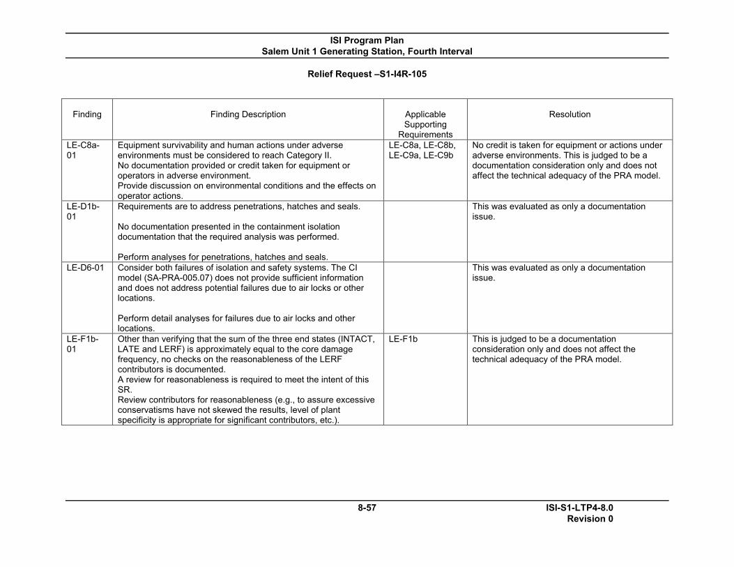
ISI Program Plan Salem Unit 1 Generating Station, Fourth Interval
Relief Request –S1-I4R-105
8-57 ISI-S1-LTP4-8.0 Revision 0
Finding
Finding Description
Applicable Supporting
Requirements
Resolution
LE-C8a-01
Equipment survivability and human actions under adverse environments must be considered to reach Category II. No documentation provided or credit taken for equipment or operators in adverse environment. Provide discussion on environmental conditions and the effects on operator actions.
LE-C8a, LE-C8b, LE-C9a, LE-C9b
No credit is taken for equipment or actions under adverse environments. This is judged to be a documentation consideration only and does not affect the technical adequacy of the PRA model.
LE-D1b-01
Requirements are to address penetrations, hatches and seals. No documentation presented in the containment isolation documentation that the required analysis was performed. Perform analyses for penetrations, hatches and seals.
This was evaluated as only a documentation issue.
LE-D6-01 Consider both failures of isolation and safety systems. The CI model (SA-PRA-005.07) does not provide sufficient information and does not address potential failures due to air locks or other locations. Perform detail analyses for failures due to air locks and other locations.
This was evaluated as only a documentation issue.
LE-F1b-01
Other than verifying that the sum of the three end states (INTACT, LATE and LERF) is approximately equal to the core damage frequency, no checks on the reasonableness of the LERF contributors is documented. A review for reasonableness is required to meet the intent of this SR. Review contributors for reasonableness (e.g., to assure excessive conservatisms have not skewed the results, level of plant specificity is appropriate for significant contributors, etc.).
LE-F1b This is judged to be a documentation consideration only and does not affect the technical adequacy of the PRA model.
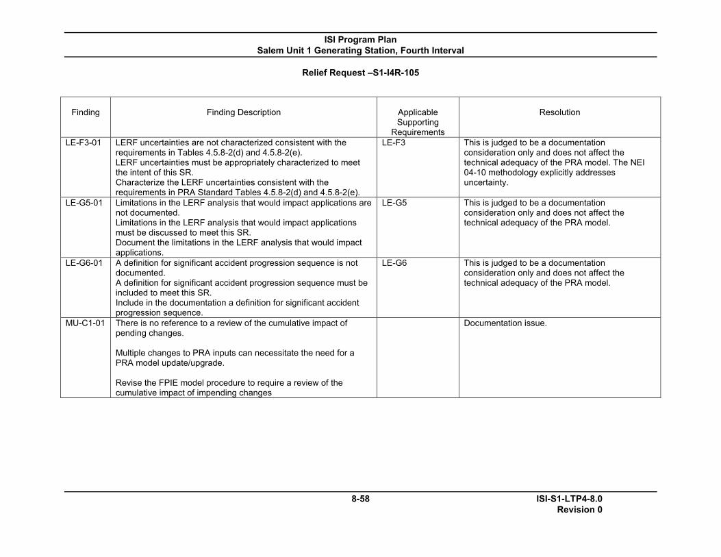
ISI Program Plan Salem Unit 1 Generating Station, Fourth Interval
Relief Request –S1-I4R-105
8-58 ISI-S1-LTP4-8.0 Revision 0
Finding
Finding Description
Applicable Supporting
Requirements
Resolution
LE-F3-01 LERF uncertainties are not characterized consistent with the requirements in Tables 4.5.8-2(d) and 4.5.8-2(e). LERF uncertainties must be appropriately characterized to meet the intent of this SR. Characterize the LERF uncertainties consistent with the requirements in PRA Standard Tables 4.5.8-2(d) and 4.5.8-2(e).
LE-F3 This is judged to be a documentation consideration only and does not affect the technical adequacy of the PRA model. The NEI 04-10 methodology explicitly addresses uncertainty.
LE-G5-01 Limitations in the LERF analysis that would impact applications are not documented. Limitations in the LERF analysis that would impact applications must be discussed to meet this SR. Document the limitations in the LERF analysis that would impact applications.
LE-G5 This is judged to be a documentation consideration only and does not affect the technical adequacy of the PRA model.
LE-G6-01 A definition for significant accident progression sequence is not documented. A definition for significant accident progression sequence must be included to meet this SR. Include in the documentation a definition for significant accident progression sequence.
LE-G6 This is judged to be a documentation consideration only and does not affect the technical adequacy of the PRA model.
MU-C1-01 There is no reference to a review of the cumulative impact of pending changes. Multiple changes to PRA inputs can necessitate the need for a PRA model update/upgrade. Revise the FPIE model procedure to require a review of the cumulative impact of impending changes
Documentation issue.
ISI Program Plan Salem Unit 1 Generating Station, Fourth Interval
9-1 ISI-S1-LTP4-9.0 Revision 0
9.0 REFERENCES
The references used to develop and maintain the Inservice Inspection Plan include:
1) Code of Federal Regulations, Title 10, Energy. - Part 50, Paragraph 2, "Definitions", the definition of "Reactor Coolant Pressure Boundary". - Part 50, Paragraph 50.55a, "Codes and Standards".
2) ASME Boiler and Pressure Vessel Code, Section XI, Division 1, "Rules for Inservice Inspection of Nuclear Power Plant Components;”
1971, Winter 1972 Addenda (Preservice) 1974, Summer 1975 Addenda (1st Interval ISI) 1983, Summer 1983 Addenda (2nd Interval ISI) 1995 Edition up through and including 1996 Addenda (3rd
Interval ISI-1st Period, 1st Outage Only) 1998 Edition up through and including 2000 Addenda (3rd
Interval ISI) 2004 Edition (4th Interval ISI)
3) Procedures ER-AA-330, “Conduct of Inservice Inspection Activities”,
ER-AA-330-001, “Section XI Pressure Testing”, ER-AA-330-002, “Inservice Inspection of Welds and Components”, ER-AA-330-003, “Visual Examination of Section XI Component Supports”, and ER-SH-330-0009, PSEG Nuclear Repair Program Manual.
4) Salem Unit 1 Generating Station ISI Classification Basis Document (ISI-S1-LTP4-BASIS), Fourth Ten-Year Inspection Interval.
5) EPRI Topical Report TR-112657, Rev. B-A, Final Report, “Revised Risk-Informed Inservice Inspection Evaluation Procedure”, December 1999.
6) USNRC SER related to EPRI Topical Report TR-112657, Rev. B, Final Report, “Revised Risk-Informed Inservice Inspection Evaluation Procedure, July 1999”, dated October 28, 1999.
7) EPRI Topical Report TR-1006937, Rev. 0-A, “Extension of the EPRI Risk-Informed Inservice Inspection (RI-ISI) Methodology to Break Exclusion Region (BER) Programs”, August 2002.
8) USNRC SER related to EPRI Topical Report TR-1006937, Rev. 0, “Extension of the EPRI Risk-Informed Inservice Inspection (RI-ISI) Methodology to Break Exclusion Region (BER) Programs”, dated June 27, 2002.

ISI Program Plan Salem Unit 1 Generating Station, Fourth Interval
9-2 ISI-S1-LTP4-9.0 Revision 0
9) Procedure ER-AA-330-014, “Risk Informed Inservice Inspection Program Implementation.”
10) USNRC Regulatory Guide 1.14, “Reactor Coolant Pump Flywheel Integrity.”
11) USNRC Regulatory Guide 1.147, Revision 16, “Inservice Inspection Code Case Acceptability, ASME Section XI, Division 1”
12) NUREG-0578, “TMI-2 Lessons Learned Task Force Status Report and Short-Term Recommendations.”
13) WCAP-16913-P R1, “Operability Assessment and Plant Applicability Evaluation for Pressurizer Heater Sleeve Leakage in Westinghouse Designed Pressurizers.”
14) EPRI Guideline, MRP-139, “Material Reliability Program: Primary System Piping Butt Weld Inspection and Evaluation Guideline.”
15) EPRI Guideline, MRP-192, “Materials Reliability Program: Assessment of RHR Mixing Tee Thermal Fatigue in PWR Plants.”
16) Salem Unit 1 ISI Selection Document, Fourth ISI Interval