safety rules for radio installations: comprising part 5 of
TRANSCRIPT

A11101 fifiMflOS


Bureau of Standards
SEP 1 2 1930
^8 14 5-
DEPARTMENT OF COMMERCE BUREAU OF STANDARDS George K. Burgess, Director
SAFETY RULES FOR RADIO INSTALLATIONS
HANDBOOK OF THE BUREAU OF STANDARDS, No. 9

I

DEPARTMENT OF COMMERCE BUREAU OF STANDARDS
George K. Burgess, Director
HANDBOOK SERIES OF THE BUREAU OF STANDARDS, No. 9
SAFETY RULES FOR RADIO INSTALLATIONS
COMPRISING PART 5 OF THE FOURTH EDITION
NATIONAL ELECTRICAL SAFETY CODE
JULY 15, 1926
PRICK, 70 CENTS
Sold only by the Superintendent of Documents, Government Printing Office
Washington, D. C.
WASHINGTON
GOVERNMENT PRINTING OFFICE
132S
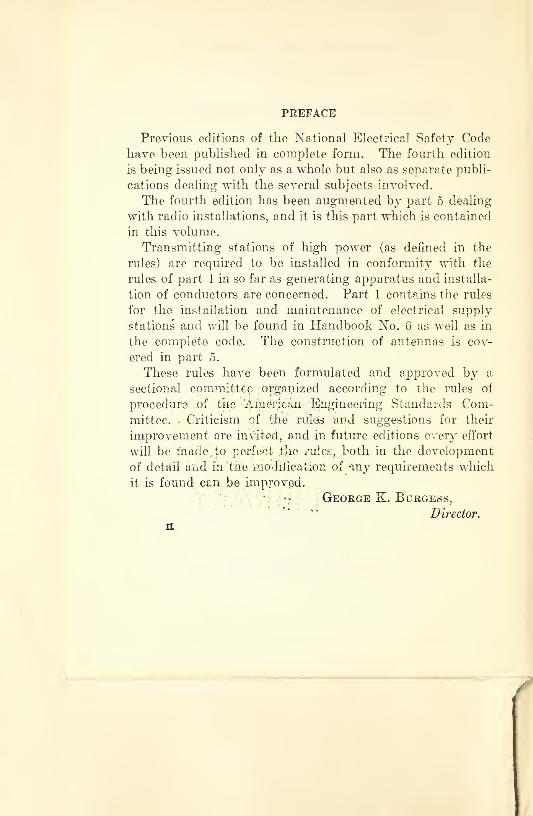
PREFACE
Previous editions of the National Electrical Safety Code
have been published in complete form. The fourth edition
is being issued not only as a whole but also as separate publi¬
cations dealing with the several subjects involved.
The fourth edition has been augmented by part 5 dealing
with radio installations, and it is this part which is contained
in this volume.
Transmitting stations of high power (as defined in the
rules) are required to be installed in conformity with the
rules of part 1 in so far as generating apparatus and installa¬
tion of conductors are concerned. Part 1 contains the rules
for the installation and maintenance of electrical supply
stations and will be found in Handbook No. 6 as well as in
the complete code. The construction of antennas is cov¬
ered in part 5.
These rules have been formulated and approved by a
sectional committee ; organized according to the rules of
procedure ;of the 'American Engineering Standards Com¬
mittee. * Criticism of tfie rules, and suggestions for their
improvement are invited, and in future editions every effort
will be made To perfect file, rules, both in the development
of detail and in the modification of any requirements which
it is found can be improved.
' *• George K. Burgess, f c i t e c c c c c o 7
Director. n

CONTENTS
Page
Definitions_ 1 Sec. 50. Scope_ 5
500. Scope___ 5
Sec. 51. Classification of radio stations_ 5 510. Classification of radio stations_ 5
Sec. 52. Antenna and counterpoise installation_ 6 520. Application of rules_ 6
521. General requirements_ 6
522. Locations to be avoided_ 7 523. Ordinary construction of antennas_ 7
524. Special construction of antennas_ 12
525. Guarding of antennas_ 14
Sec. 53. Lead-in conductors_ 15 530. Application of rules_ 15
531. Material_ 15
532. Size___ 15 533. Installation of lead-in conductor_ 15
Sec. 54. Construction at building entrance_ 17 540. Application of rules_ 17 541. Entrance bushing_ 17
542. Creepage and air-gap distance_ 17 543. Mechanical protection of bushings_ 17
Sec. 55. Protective and operating grounding conductors_ 17 550. Application of rules_ 17
551. General_ 18
552. Material and size_ 18 553. Installation of grounding conductors_ 18
Sec. 56. Ground connections_ 19 560. Application of rules_ 19
561. General_ 19
562. Gas pipe not to be used_ 19
563. Water-pipe grounds_ 19
564. Attachment to pipes___ 19 565. Driven or buried grounds_ 19
566. Attachment to ground rod or plate_ 20
in

IV CONTEXTS
Page
Sec. 57. Protective devices._ 20
570. Application of rules_ 20
571. Lightning arrester_ 20
572. Antenna grounding switch_ 21
573. Protection against kick-back_ 22
Sec. 58. Connection to power supply lines_ 23 580. Connection to power supply lines_ 23
Sec. 59. Batteries_ 24
590. Application of rules_ 24
591. Care in handling_ 24
592. Storage battery_ 24

SAFETY RULES FOR RADIO INSTALLATIONS
COMPRISING PART 5 OF THE FOURTH EDITION, NATIONAL ELECTRICAL SAFETY CODE
DEFINITIONS
Alive or live means electrically connected to a source of
potential difference, or electrically charged so as to have a
potential different from that of the earth. The term “live”
is sometimes used in place of the term “current carrying”
where the intent is clear, to avoid repetitions of the longer
term.
Antenna conflict means that an antenna or its guy wire
is at a higher level than a supply or communication conduc¬
tor and approximately parallel thereto, provided the break¬
ing of the antenna or its support will be likely to result in
contact between the antenna or guy wire and the supply
or communication conductor.
Circuit means a conductor or system of conductors
through which an electric current is intended to flow.
Coirniuiiicatioii lines means the conductors and their
supporting or containing structures which are located out¬
side of buildings and are used for public or private signal or
communication service and which operate at not exceeding
400 volts to ground or 750 volts between any two points of
the circuit and the transmitted power of which does not ex-
1

2 DEFINITIONS
ceed 150 watts. When operating at less than 150 volts,
no limit is placed on the capacity of the system.
Note: Telephone, telegraph, messenger-call, clock, fire or police alarm, and other systems conforming with the above are included.
Lines used for signaling purposes, but not included under the above definitions, are considered as supply lines of the same voltage and are to be so run.
Exception is made under certain conditions for com¬ munication lines used in the operation of supply lines.
Conductor means a metallic conducting material, usually
in the form of a wire or cable, suitable for carrying an electric
current. Does not include bus bars.
Current-carrying part means a part intended to be con¬
nected in an electric circuit to a source of voltage. Non¬
current-carrying parts are those not intended to be so
connected.
Dead means free from any electrical connection to a
source of potential difference and from electric charge;
not having a potential different from that of the earth.
The term is used only with reference to current-carrying
parts which are sometimes alive.
Electrical supply equipment means equipment which
produces, modifies, regulates, controls, or safeguards a
supply of electrical energy. Similar equipment, however,
is not included where used in connection with signaling
systems under the following conditions:
(a) Where the voltage does not exceed 150.
(b) Where the voltage is between 150 and 400 and the
power transmitted does not exceed 3 kilowatts.
Electrical supply lines means those conductors and their
necessary supporting or containing structures which are
located entirely outside of buildings and are used for trans¬
mitting a supply of electrical energy.

DEFINITIONS 3
Electrical supply station means any building, room, or
separate space within which electrical supply equipment is
located and the interior of which is accessible, as a rule,
only to properly qualified persons.
Note: This includes generating stations and substations and generator, storage-battery, and transformer rooms, but excludes manholes and isolated transformer vaults on private premises.
Grounded means connected to earth or to some extended
conducting body which serves instead of the earth, whether
the connection is intentional or accidental.
Grounded system means a system having a permanent
and effective electrical connection to earth. This ground
connection may be at one or more points.
Note: “Effective,” as herein used, means a connection to earth of sufficiently low resistance and high current- carrying capacity to prevent any current in the ground wire from causing a harmful voltage to exist between the grounded conductors and neighboring exposed con¬ ducting surfaces which are in good contact with the earth, or with neighboring surfaces of the earth itself, under the most severe conditions which are liable to arise in practice.
Permanently grounded means having such an effective con¬
nection to the earth (by use of an underground system of
metallic pipe mains or other suitable means) as described
in the preceding paragraph.
Guarded means covered, shielded, fenced, inclosed, or
otherwise protected, by means of suitable covers or casings,
barrier rails or screens, mats or platforms, to remove the
liability of dangerous contact or approach by persons or
objects to a point of danger.
Insulated means separated from other conducting surfaces
by a dielectric substance or air space permanently offering

4 DEFINITIONS
a high resistance to the passage of current and to disruptive
discharge through the substance or space.
Note: When any object is said to be insulated, it is understood to be insulated in suitable manner for the conditions *to which it is subjected. Otherwise, it is, within the purpose of these rules, uninsulated. In¬ sulating covering of conductors is one means for making the conductors insulated.
Insulating (where applied to the covering of a conductor,
or to clothing, guards, rods, and other safety devices) means
that a device, when interposed between a person and current-
carrying parts, protects the person making use of it against
electric shock from the current-carrying parts with which the
device is intended to be used; the opposite of conducting.
Eural districts means all places not urban, usually in the
country, but in some cases within city limits.
Service means the connecting conductors by which a sup¬
ply of electrical energy is carried from a supply line to the
building or premises served. For overhead circuits, it
includes the conductors from the last line pole to the service
switch or fuse. The portion of an overhead service between
the pole and building is designated as “service drop.”
Switch means a device for opening and closing or for
changing the connection of a circuit. In these rules a
switch will always be understood to be manually operated,
unless otherwise stated.
Urban districts means thickly settled areas (whether in
cities or suburbs) or where congested traffic often occurs.
A highway, even though in the country, on which the traffic
is often very heavy, is considered as urban.
Voltage or volts means the highest effective voltage
between any two conductors of the circuit concerned, except
that in grounded multiwire circuits, not exceeding 750 volts
between outer conductors, it means the highest effective
voltage between any wire of the circuit and the ground.

DEFINITIONS 5
In ungrounded circuits not exceeding 750 volts, voltage to
ground means the voltage of the circuit.
When one circuit is directly connected to another circuit
of higher voltage (as in the case of an au to transformer),
both are considered as of the higher voltage, unless the
circuit of lower voltage is permanently grounded. Direct
connection implies electrical connection as distinguished
from connection merely through electromagnetic or electro¬
static induction.
Wire gauges: The American Wire Gauge (A. W. G.),
otherwise known as Brown & Sharpe (B. & S.), is the stand¬
ard gauge for copper, aluminum, and other conductors,
excepting steel, for which the Steel Wire Gauge (Stl. W. G.)
is used throughout these rules.
SEC. 50. SCOPE
500. Scope.
The rules of part 5 apply to radio transmitting and re¬
ceiving installations including antennas, counterpoise
wires, lead-in conductors, grounding conductors, ground¬
ing connections, protective devices and batteries. The
rules do not apply to antennas used for coupling carrier-
current equipment to line conductors.
In case the installation is covered by more than one rule,
the superior requirement shall apply.
SEC. 51. CLASSIFICATION OF RADIO STATIONS
510. Classification of Radio Stations.
For the purpose of these rules radio stations are clas¬
sified as follows:
A. Receiving Stations.
101333°—26-2

6 SEC. 51—CLASSIFICATION OF STATIONS
510—Continued.
B. Transmitting Stations.
1. LOW POWER.
Transmitting stations to which the power sup¬
plied is less than 100 watts and where the
voltage of the power supplied is less than 400
volts.
2. MEDIUM POWER.
Transmitting stations not classified as low power
or high power.
3. PIIGH POWER.
Transmitting stations to which the power sup¬
plied is greater than 1,000 watts or where the
voltage of the power supplied is greater than
2,000 volts.
SEC. 52. ANTENNA AND COUNTERPOISE INSTALLATION
520. Application of Rules.
These rules apply to the following:
A. Outdoor Antennas of all Classes of Receiving and
Transmitting Stations. (There are no requirements
for indoor antennas.)
B. Counterpoise Wires.
521. General Requirements.
A. Counterpoise Wires.
Counterpoise wires shall conform to the requirements
for antennas similarly located.
B. Antennas of Receiving and Low-Power Transmitting
Stations.
Such antennas shall, in general, comply with the
requirements for the construction of communication
lines for public use in similar situations.

RULE 521-GENERAL REQUIREMENTS 7
521—Continued.
C. Antennas of Medium and High-Power Transmitting vStations.
Such antennas shall, in general, comply with the requirements for the construction of supply lines in similar situations.
522. Locations to be Avoided.
The following situations should be avoided in erecting antennas and guy wires:
A. Attachments to supply or communication poles.
B. Crossings over railroad tracks or public highways.
C. Crossings over supply or communication conductors.
D. Crossings under supply or communication conduc¬
tors.
E. Antenna conflicts with supply or communication
conductors. (See definition of “Antenna Con¬
flict.7’)
523. Ordinary Construction of Antennas.
Antennas shall be constructed according to the require¬
ments of rule 523 when they do not cross over railroad tracks, supply conductors, or communication con¬
ductors and do not conflict with supply or communica¬
tion conductors.
A. Antenna Conductors.
1. MATERIAL
(a) Receiving Antennas. No requirements.
(b) Transmitting Antennas. Antennas shall
be of copper, bronze, copper-covered steel,
or other metal which will not corrode ex¬
cessively under the prevailing conditions.
2. SIZE.
Antenna conductor sizes shall be not less than
given in Table 1.

8 SEC. 52-ANTENNAS
523. A—Continued.
Table 1.—Antenna Conductor Sizes—Ordinary Construction
Material
Receiving antennas
Transmitting antennas
Low power M edium and high power
Size 1 Ia.w.g. i l
Diameter c. | mzc
A.W.G. Diameter Size A.W.G.
Diame¬ ter
Copper: Soft-drawn---
j
14 i
Inch 0. 0G4 14
Inch 0.064
Inch 0.144
Medium-drawn_j 14 .064 14 .064 8 .123
Hard-drawn_ j
[I 14 . 064 14 .064 10 . 102
Bronze or copper-covered steel _ _ 17 .045 14 .064 12 .CS1
3. STRENGTH.
(a) Antennas of Eecexving and Low-Power
Transmitting Stations. No requirements.
(b) Antennas of Medium and High-Power
Transmitting Stations. The strength of
the antenna conductor shall be not less than
that of No. 10 A. W. G. (diameter 0.102
inch) hard-drawn copper.
B. Antenna Insulators.
1. ANTENNAS OF RECEIVING AND LOW-POWER TRANS¬
MITTING STATIONS.
No requirements.

RULE 523-ORDINARY ANTENNAS 9
523. B—Continued.
2. ANTENNAS OF MEDIUM AND HIGH-POWER TRANS¬
MITTING STATIONS.
Insulators shall be of noncombustible material
and shall have a creepage distance of not less
than 10 inches.
C. Antenna Supports.
1. STRENGTH OF SUPPORTS.
Supports shall be of such initial size as to carry
the vertical load and where necessary shall be
guyed or braced so as to withstand the trans¬ verse and longitudinal loads to which they may
be subjected.
2. ROOF SUPPORTS.
Antenna supports erected on roofs shall be of
rigid construction, and, where necessary shall
be arranged to distribute the load over the roof.
Such supports shall be erected so that they are
not dependent in any way on the antenna for
stability.
3. CHIMNEYS
The attachment of antennas to chimneys should
be avoided.
4. GROUNDING METAL SUPPORTS ON ROOFS.
Metal poles or masts extending more than 10
feet above the supporting building shall be
permanently and effectively grounded.
5. TREES.
Where a tree is used as an antenna support,
sufficient sag (or other means) shall be provided
to keep the tension in the antenna safely below
the breaking strength when the tree sways in the
wind.

10 SEC. 52-ANTENNAS
523—Continued.
D. Attaching Antennas to Supports.
1. STRENGTH OF ATTACHMENT.
The means used for attaching the antenna to the
support shall be such as to withstand a greater
load than that which will break the conductor itself.
2. ATTACHMENT ON SMALL POLES.
If the pole is not strong enough to support a
person, some arrangement shall be provided to
draw up the antenna from the ground.
E. Minimum Clearance Above Ground.
1. SPANS 150 FEET OR LESS IN LENGTH.
Antenna conductors shall have clearances above
ground as given in Table 2.
Table 2.—Minimum Antenna Clearances Above Ground
Location
Receiving and low-
power antennas
| Medium ;
and high- 1 power
antennas j
Above streets and other traveled roadways. Feet
18 Feet
28
Along road in rural districts _ __ 15 28
Above roadways to residences garages 10
Above spaces or ways accessible only to pedestrians ___ 10

RULE 523-ORDINARY ANTENNAS 11
523. E—Continued.
2. SPANS EXCEEDING 150 FEET IN LENGTH. For
such spans the above clearances shall be increased
by 0.1 foot for each 10 feet in excess of 150 feet.
F. Minimum Clearances below Supply and Com¬
munication Conductors.
Antennas shall have the following clearances from
conductors under which they cross:
Table 3.—Minimum Antenna Clearances Below Other Conductors
Crossing under—
Receiving and low-
power antennas
Medium and high-
power antennas
Communication conductors _ Feet
2 Feet
10
Supply conductors, 0 to 750 volts j 4 10
Supply conductors exceeding 750 volts_| 6 10
G. Clearances from Combustible Material.
Antennas of medium and high-power transmitting
stations shall be placed so that an air gap of at
least 10 inches exists between the antenna and the
nearest combustible material.

12 SEC. 52-ANTENNAS
524. Special Construction of Antennas.
Antennas shall be specially constructed according to
the following requirements when they cross over rail¬
road tracks, supply conductors, or communication
conductors, or are in conflict with supply or com¬
munication conductors.
A. Recommendation against Locating Antennas in
Situations Where Special Construction is Required.
It is strongly recommended that the installation of
antennas in these special situations be avoided. If
such locations are employed it must be recognized
that special hazards are introduced and that great
care is necessary in the construction and mainte¬
nance of antennas to avoid contact with supply or
communication conductors or to avoid the reduction
of clearance over railroad tracks.
B. Construction of Antennas Crossing Over or Con¬
flicting with Service Loops 0 to 150 Volts to Ground.
Antennas constructed in these situations shall con¬
form to the requirements for the ordinary construc¬
tion of antennas (rule 523) and, in addition, with the
requirements set. forth below for splices (rule 524,
C, 2) and for minimum clearances above com¬
munication and supply line conductors (rule 524,
C, 4).
C. Construction of Antennas Crossing Over or Con¬
flicting with Communication Conductors or Supply
Conductors 0 to 750 Volts.
1. ANTENNA CONDUCTOR STRENGTH.
The strength of the antenna conductor shall be
not less than that of hard-drawn copper of the
following sizes:

RULE 524—SPECIAL ANTENNAS 13
524. C. 1—Continued.
Span length
Size of hard-drawn copper
Size A. W. G.
Diameter
Inch 0 to 150 feet_ 8 0. 128 Exceeding 150 feet_ __ i
i 6 . 162
2. SPLICES.
Splices in antenna spans shall be made with a
suitable twisted-sleeve connector which will
provide a strong unsoldered joint.
3. ANTENNA SUPPORTS.
(a) Material. The poles for supporting an¬
tennas shall be of steel, concrete, or wood.
Wood poles shall be free from observable
defects that would decrease their strength
or durability.
(b) Size. Wood poles shall have a top di¬
ameter of not less than 6 inches.
(c) Setting. Poles shall be set to such a depth
and in such a manner that any applied load
will break the pole before the butt is pulled
loose from its setting.
4. MINIMUM CLEARANCES ABOVE COMMUNICATION
AND SUPPLY CONDUCTORS, 0 TO 750 VOLTS.
Antennas crossing over such conductors shall
have the following clearances:

14 SEC. 52-ANTENNAS
524. C. 4—Continued. Feet
Antennas of receiving and low-power
transmitting stations_ 6
Antennas of medium and higli-power
transmitting stations_ 10
D. Antennas Crossing over Railroads or Crossing
over or Conflicting with Supply Lines Exceeding
750 volts.
1. ANTENNAS OF RECEIVING AND LOW-POWER TRANS¬
MITTING STATIONS.
Such antennas shall conform to the require¬
ments for communication lines for public use
in similar situations as far as grades of construc¬
tion and clearances from all other wires and
from ground are concerned. (See N. E. S.
Code, part 2.)
2. ANTENNAS OF MEDIUM AND HIGH-POWER TRANS¬
MITTING STATIONS.
Such antennas shall conform to the require¬
ments for supply lines in similar situations as
far as grades of construction and clearances
from all other wires and from ground are con¬
cerned. (See N. E. S. Code, part 2.)
525. Guarding of Antennas.
Antennas for transmitting stations shall be installed
or protected so as to be inaccessible to unauthorized
persons.

RULE 530-APPLICATION 15
SEC. 53. LEAD-IN CONDUCTORS
530. Application of Rules.
The requirements of this section apply to lead-in
conductors of receiving stations and transmitting
stations of low and medium power. Lead-in conduc¬
tors of high-power transmitting stations shall meet
such requirements of part 1 “Supply stations” as
apply.
531. Material.
Lead-in conductors shall be of copper, bronze, copper-
covered steel, or other metal which wull not corrode
excessively under the prevailing conditions.
532. Size.
A. Receiving Stations.
For receiving stations the size of lead-in conductor
shall be not less than No. 14. A. W. G. (0.064
inch) if of copper, or less than No. 17 A. W. G.
(0.045 inch) if of bronze or copper-covered steel.
B. Low and Medium Power Transmitting Stations.
For such transmitting stations the lead-in conductor
shall be not less than No. 14 A. W. G. (0.064 inch).
533. Installation of Lead-in Conductor.
A. From Antenna to First Building Attachment.
This section of the lead-in wire shall conform to the requirements for antennas similarly located.
B. From First Building Attachment to Building Entrance.
This section of the lead-in conductor shall be in¬
stalled and maintained so that it can not swing
closer to open supply conductors than the following
distances:

16 SEC. 53-LEAD-IN CONDUCTORS
533. B—Continued. Feet
Supply lines 0 to 750 volts__2
Supply lines exceeding 750 volts.__ 10
Exception.—The 2-foot clearance may he reduced if the lead-in conductor is separated from supply conductors by a continuous and firmly fixed non¬ conductor which will maintain permanent separa¬ tion. This nonconductor shall be in addition to any insulating covering on the wires.
C. From Building Entrance to Set.
1. RECEIVING STATIONS.
(a) Lead-in conductors shall be securely fas¬
tened in a workmanlike manner.
(b) Clearance between lead-in conductor and
any supply conductor not in conduit shall
not be less than 2 inches.
Exception.—This 2-inch clearance does not apply if a firmly fixed nonconductor such as porce¬ lain tube affords a permanent separation. This nonconductor shall be in addition to any insulating covering on the wires.
2. LOW AND MEDIUM POWER TRANSMITTING STA¬
TIONS.
(a) Lead-in conductors shall be securely fas¬
tened to suitable insulators.
(b) Clearance between lead-in conductor and
any supply wire shall be at least 5 inches.
(c) Lead-in conductors shall be installed and
protected to prevent persons from readily
coming into accidental contact with them.
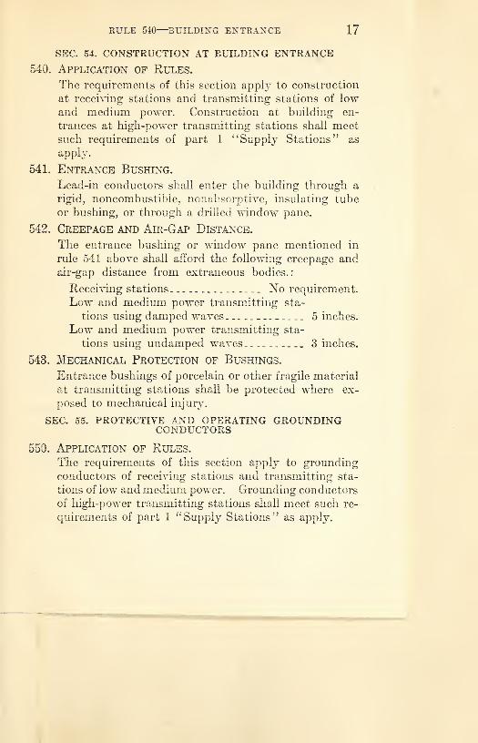
RULE 540—BUILDING ENTRANCE 17
SEC. 54. CONSTRUCTION AT BUILDING ENTRANCE
540. Application of Rules.
The requirements of this section apply to construction
at receiving stations and transmitting stations of low and medium power. Construction at building en¬
trances at high-power transmitting stations shall meet
such requirements of part 1 “Supply Stations” as
apply.
541. Entrance Bushing.
Lead-in conductors shall enter the building through a
rigid, noncombustible, nonabsorptive, insulating tube
or bushing, or through a drilled window pane.
542. Creepage and Air-Cap Distance.
The entrance bushing or window pane mentioned in
rule 541 above shall afford the following creepage and
air-gap distance from extraneous bodies.:
Receiving stations_ No requirement. Low and medium power transmitting sta¬
tions using damped waves_-_5 inches.
Low and medium power transmitting sta¬
tions using undamped waves_ 3 inches.
543. Mechanical Protection of Bushings.
Entrance bushings of porcelain or other fragile material
at transmitting stations shall be protected where ex¬ posed to mechanical injury.
SEC. 55. PROTECTIVE AND OPERATING GROUNDING CONDUCTORS
550. Application of Rules.
The requirements of this section apply to grounding
conductors of receiving stations and transmitting sta¬
tions of low and medium power. Grounding conductors
of high-power transmitting stations shall meet such re¬
quirements of part 1 “Supply Stations’’ as apply.

18 SEC. 55-GROUNDING CONDUCTORS
551. General.
The protective grounding conductor may be used also
as the operating grounding conductor.
552. Material and Size.
A. Receiving Stations.
1. MATERIAL.
No requirements.
2. SIZE.
(а) Operating Grounding Conductor. No
requirements.
(б) Protective Grounding Conductor. This
conductor shall not be smaller than the
lead-in conductor.
B. Transmitting Stations.
The operating and grounding conductors shall have
strength and conductance per unit length not less
than No. 14 A. W. G. (0.064 inch) hard-drawn cop¬
per.
553. Installation of Grounding Conductors.
A. Method of Running.
1. Grounding conductors shall be run in as straight
a line as possible from the set or the protective
device to a good permanent ground.
2. Grounding conductors may be run either inside
or outside of the building.
Recommendation.—It is recommended that the protective grounding wire for low and medium power transmitting stations be run outside of the building.
B. Mechanical Protection.
Grounding conductors shall be guarded where ex¬
posed to mechanical injury.

RULE 553—GROUNDING CONDUCTOR 19
553—Continued.
C. Insulation.
Grounding conductors may be of insulated or bare
wire and need not be run on insulating supports.
SEC. 56. GROUND CONNECTIONS
580. Application of Rules.
The requirements of this section apply to ground con¬
nections for all classes of transmitting stations, and to
protective ground connections of receiving stations.
561. General.
Grounding shall be done in accordance with the follow¬
ing methods. (See section 9; N. E. S. Code, for com¬
plete rules for grounding.)
562. Gas Pipe Not to Be Used.
Gas pipe should not be used for grounding purposes.
583. Water-pipe Grounds.
The ground connections shall be made to a cold-water
pipe where such pipe is available and is in service and
connected to the street mains. An outlet pipe from a
water tank fed by a street main or a well may be used,
provided such outlet pipe is adequately bonded to the
inlet pipe connected to the street water main or well.
564. Attachment to Pipes.
Grounding conductors shall be attached to pipes by
means of suitable ground clamps. The entire surface
of the pipe to be covered by the clamp shall be thor¬
oughly cleaned.
565. Driven or Buried Grounds.
If cold-water pipes are not available, ground connec¬
tions may be made to a galvanized iron pipe or to a rod
driven into permanently damp earth or to a metal plate
or other body of metal buried similarly.

20 SEC. 56-GROUND CONNECTIONS
566. Attachment to Ground Rod or Plate.
The grounding conductor shall be attached to the rod,
buried plate, or other body of metal so as to give re¬
liable connection both mechanically and electrically.
This connection shall be made so that it will not fail
through corrosion even when the joint is buried in the
earth. SEC. 57. PROTECTIVE DEVICES
570. Application of Rules.
The requirements of this section apply to protective
devices for receiving stations and transmitting stations
of low and medium power. Protective devices for
high-power transmitting stations shall meet such re¬
quirements of part 1 “ Supply Stations ” as appty.
571. Lightning Arrester.
A. Where Required.
Each lead-in conductor of a receiving station shall
be provided with a lightning arrester, whether or not
an antenna grounding switch is used.
B. Operating Voltage.
The lightning arrester shall be such as to operate at
a potential of 500 volts or less.
C. Location.
The arrester may be located outside the building as
near as practicable to the point of entrance, or in¬
side the building between the point of entrance and
the receiving set and convenient to a ground. The
arrester shall not be placed in the immediate vicinity
of easily ignitable material or in a location exposed
to dust, inflammable gases, or flyings of combustible
materials.

RULE 572—GROUNDING SWITCH 21
572. Antenna Grounding Switch.
A. Where Required.
An antenna grounding switch shall be used at low
and medium power transmitting stations. An an¬
tenna grounding switch is not required at receiving
stations, but may be used in addition to the light¬
ning arrester.
B. Type of Switch.
1. RECEIVING STATIONS.
The switch should be of the single-pole double¬
throw type.
2. LOW AND MEDIUM POWER TRANSMITTING STA¬
TIONS. The switch shall be of the double-throw type
and shall meet the following requirements:
Minimum break distance_ 4 inches.
Minimum cross-section of switch blade
_ Vs inch x y, inch.
Switch base: Nonabsorptive insulating material.
C. Location.
The switch may be located either outside or inside
the building. The switch should be placed in the
most direct line between the lead-in conductor and
the point where the grounding connection is made.
D. Clearance for Live Switch Parts.
The switch shall be mounted so that its current-
carrying parts will clear the building wall or con¬
ductors not connected to the switch by the following
distances:
Switches for receiving stations: No clearance re¬
quired.

22 SEC. 57-PROTECTIVE DEVICES
572. D—Continued.
Switches for low and medium power transmitting
stations:
Damped-wave sets_ __ 5 inches.
Undamped-wave sets_ 3 inches.
E. Method of Connection.
1. RECEIVING STATIONS.
The switch shall be wired so that the antenna
lead-in conductor can be disconnected from the
set and connected to the grounding conductor.
When in the grounding position the switch shall
short-circuit the lightning arrester.
2. LOW AND MEDIUM POWER TRANSMITTING STA¬
TIONS.
No requirements.
F. Operation of Switch.
1. RECEIVING STATIONS.
No requirements.
2. LOW AND MEDIUM POWER TRANSMITTING STA¬
TIONS.
Antenna and counterpoise lead-in conductors of
low and medium power transmitting stations
shall be connected to the grounding conductor
whenever the station is not in use.
573. Protection Against Kick-Back.
A. Where Required.
Protection should be provided at low and medium
power transmitting stations where necessary to
protect the supply system against high-potential
surges and “kick-backs.”

RULE 573-KICK-BACK PROTECTION 23
573 B. Apparatus—Continued.
Any of the following methods may be used:
1. Two condensers usually of 0.1 to 0.5 micro¬
farad capacity, and capable of withstanding
five times the normal voltage to which they
are subjected placed in series with one another
across the supply line with mid-point between
condensers grounded. Across (in parallel with)
each of these condensers shall be connected a
shunting fixed spark gap capable of not more
than 1/32 inch separation.
2. Two vacuum-tub e-type protectors in series with
one another across the line with the mid-point
grounded (if the line voltage does not exceed
110 volts).
3. Electrolytic lightning arresters, such as the
aluminum-cell type.
C. Location.
Apparatus for protection against “kick-back” should
be installed across the supply conductors as near as
possible to each radio transformer, rotary spark gap,
motor, and generator (in motor-generator sets), or
other auxiliary apparatus.
SEC. 58. CONNECTION TO POWER SUPPLY LINES
580. Connection to Power Supply Lines.
Devices used in connection with power supply lines
and methods of wiring shall be in accordance with the
rules covering permanent or portable fixtures, devices,
and appliances (see N. E. S. Code, sec. 37).

24 SEC. 59—BATTEKIES
SEC. 59. BATTERIES
590. Application of Rules.
The requirements of this section apply to batteries for
receiving stations and transmitting stations of low and
medium power. Battery installations for high-power
transmitting stations shall meet such requirements of
part 1 “Supply Stations” as apply.
591. Care in Handling.
Care shall be used in handling batteries in order to
avoid contacts with terminals having a high enough
difference of potential to cause shock.
592. Storage Battery.
A. Wiring.
The wiring of storage batteries used with radio
receiving equipment shall be subject to the rules
covering the wiring of permanent or portable fixtures,
devices, and appliances (see N. E. S. Code, sec. 37).
B. Ventilation.
Storage batteries shall be located where there is
adequate ventilation.
C. Precautions.
1. Open flames shall be kept away from storage
batteries.
2. Storage batteries should be placed on trays or
mats of lead, rubber, or other material which
will not be affected by the electrolyte.
D. Large Battery Installations.
Installation of nonportable storage batteries of
more than 50 kilowatt-hour capacity at the 8-hour
rate of discharge, if used for radio, shall comply
with section 13 and rule 353 of the N. E. S. Code.


Wii
iiliW
lKlI
iW