safety recall n65 / nhtsa 13v-610 transmission … recall n65 / nhtsa 13v-610 transmission output...
TRANSCRIPT
Copyright 2014, Chrysler Group LLC, All Rights Reserved
March 2014 Dealer Service Instructions for:
Safety Recall N65 / NHTSA 13V-610
Transmission Output Shaft
2013 (LD) Dodge Charger
(LX) Chrysler 300
NOTE: This recall applies only to the above vehicles equipped with a 3.6L engine
(sales code ERB), 8 speed automatic transmission (sales code DFG) and All Wheel
Drive (sales code 590) built from November 24, 2012 through February 16, 2013
(MDH 112422 through 021605).
2013 (DS) RAM Truck (1500 series)
NOTE: This recall applies only to the above vehicles equipped with a 3.6L engine
(sales code ERB), 8 speed automatic transmission (sales code DFG) and four
wheel drive (sales code 5I4) built from January 12, 2013 through June 27, 2013
(MDH 011205 through 062714).
The transmission output shaft on about 4,100 of the above vehicles may fracture
while driving. If the vehicle experiences this condition there will be a loss of
motive power. The condition may also prevent the transmission from being shifted
into the “Park” position, the inability to turn off the engine, an instrument cluster
warning lamp illumination, and the vehicle could experience unintended vehicle
movement after exiting the vehicle. The above conditions could cause a crash
under certain driving conditions.
Models
IMPORTANT: Some of the involved vehicles may be in dealer new vehicle
inventory. Federal law requires you to complete this recall service on these
vehicles before retail delivery. Dealers should also consider this requirement to
apply to used vehicle inventory and should perform this recall on vehicles in for
service. Involved vehicles can be determined by using the VIP inquiry process.
Subject

Safety Recall N65 – Transmission Output Shaft Page 2
The transmission output shaft must be tested. If the transmission output shaft
breaks during the test, the transmission assembly must be replaced.
NOTE: LD and LX models must first have temporary software installed in
the Transmission Control Module (TCM) before the output shaft test can be
performed. The temporary software must be removed from the TCM after
the output shaft test is complete.
Dealers should attempt to minimize customer inconvenience by placing the owner
in a loaner vehicle if inspection determines that transmission replacement is
required and the vehicle must be held overnight.
Repair
Alternate Transportation

Safety Recall N65 – Transmission Output Shaft Page 3
Part Number Description
RL199893AE Transmission Package (All DS Models)
RL228863AB Transmission Package (LD/LX Models / sales
code ERB + NGZ / 300 H.P.)
RL149638AL Transmission Package (LD/LX Models /sales
code ERB / 290 H.P)
Each package contains the following components:
Quantity Description
1 Transmission Assembly
1 Converter, Torque
Due to the small number of involved vehicles expected to require transmission
replacement, no parts will be distributed initially. Transmission packages should
be ordered only after testing determines that replacement is required. Very
few vehicles are expected to require transmission replacement.
Part Number Description
68218925AA Fluid, Transmission (ZF 8 & 9 Speed ATF)
Transmission wire harness clips listed below can be ordered as
required should they break during transmission replacement (DS
Models Only)
Part Number Description
68257635AA Clip, Transmission Wiring Harness
68064249AA Clip, Transmission Wiring Harness
Parts Information

Safety Recall N65 – Transmission Output Shaft Page 4
The following special tools are required to perform this repair:
NPN wiTECH VCI Pod Kit
NPN Laptop Computer
NPN wiTECH Software
9546 Tool, Cooler Tube Disconnect
A. Install TCM Test Software
IMPORTANT INSTRUCTIONS: Only LX and LD models require test
software installation. Continue with Step 1. of this section.
DS models do not require test software installation. DS models continue with
Section B: Transmission Output Shaft Test.
NOTE: wiTECH must be used to perform this recall. This procedure must be
performed with software release level 14.03 or higher. If the reprogramming
flash for the TCM is aborted or interrupted, repeat the procedure.
1. Open the hood. Install a battery charger and verify that the charging rate
provides 13.0 to 13.5 volts. Do not allow the charger to time out during the
reprogramming process. Set the battery charger timer (if so equipped) to
continuous charge.
NOTE: Use an accurate stand-alone voltmeter. The battery charger volt
meter may not be sufficiently accurate. Voltages outside of the specified
range will cause an unsuccessful flash. If voltage reading is too high, apply
an electrical load by activating the park or headlamps and/or HVAC
blower motor to lower the voltage.
2. Connect the wiTECH VCI pod to the vehicle data link connector located to the
right of the hood release lever.
3. Place the ignition in the “RUN” position.
4. Open the wiTECH Diagnostic application.
Special Tools

Safety Recall N65 – Transmission Output Shaft Page 5
5. Starting at the “Select Tool” screen, highlight the row/tool for the wiPOD
device you are using. Then select “Next” at bottom right side of the screen.
6. Enter your “User id” and “Password”, then select “Finish” at the bottom of the screen.
7. From the “Vehicle View” screen, click on the TCM icon.
8. Select the engineering test flash file and click the green arrow to begin the
software update.
T0000001XX 2013 LD LX 3.6L AUTO 8 SPD AWD. This is the test flash
file for a 2013 model year LD / LX vehicles with a 3.6L engine, 8 speed
automatic transmission, and All Wheel Drive (AWD).
T0000002XX 2013 LD LX 3.6L AUTO 8 SPD AWD HO. This is the test
flash file for a 2013 model year LD / LX vehicles with a 3.6L High Output
(HO) engine (sales code NGZ), 8 speed automatic transmission, and All
Wheel Drive (AWD).
CAUTION: If the test software remains in the vehicle’s TCM after the
output shaft test, the transmission will not shift out of first gear and the
check engine light will remain illuminated.
9. Follow the screen prompts to complete the test software installation.
10. Clear all Diagnostic Trouble Codes (DTC’s).
NOTE: One active DTC will remain after clearing all DTC’s. This code
identifies the test software. The output shaft test can be performed with this
active DTC present.
11. Turn Ignition off.
12. Remove the battery charger.
13. Continue with Section B. Transmission Output Shaft Test.
CAUTION: If the test software remains in the vehicle’s TCM after the
output shaft test, the transmission will not shift out of first gear and the
check engine light will remain illuminated.
Service Procedure (Continued)
Safety Recall N65 – Transmission Output Shaft Page 6
B. Transmission Output Shaft Test
1. Start the engine and allow the engine to reach normal operating temperature.
2. Fully apply the parking brake.
3. Depress and hold down the brake pedal.
4. For DS model vehicles, shift to 4WD mode for the test procedure.
5. Shift the transmission into the “Drive” position.
6. With the transmission in the “Drive” position, apply Wide Open Throttle
(WOT) for 2 seconds and then release throttle.
NOTE: If the transmission output shaft fails during the test, an audible
“bang noise” will be heard and the engine RPM’s will flare.
CAUTION: If the transmission output shaft fails during the test, release
throttle immediately.
If the transmission output shaft is intact, after release of the park brake and
service brake, the vehicle should creep forward as it normally would while
the transmission is in the “Drive” position. Continue with Step 7 of this
procedure.
If the transmission output shaft has failed, there will be no forward
movement of the vehicle while the transmission is in the “Drive” position.
Continue with Section C. Replace Transmission Assembly (DS models) or
Section D. Replace Transmission Assembly (LD/LX models).
7. Shift the transmission into Neutral and wait 10 seconds for the transmission to
cool down.
8. Repeat Steps 6 and 7 until either the transmission output shaft fails or five stall
torque cycles are performed.
9. If the transmission output shaft has not failed after five torque cycles, drive the
vehicle for five minutes to ensure that the transmission oil temperature has
cooled down. Then continue with Step 10 of this procedure.
Service Procedure (Continued)

Safety Recall N65 – Transmission Output Shaft Page 7
10. Again, repeat Steps 6 and 7 until either the transmission output shaft fails or an
additional five stall torque cycles are performed (for a total of 10 stall torque
cycles).
11. If transmission output shaft failure does not occur in 10 stall torque cycles, the
vehicle test is complete and successful:
For DS model vehicles, return the vehicle to the customer.
For LD and LX model vehicles, continue with Section E. – Update TCM
Software.
12. If transmission output shaft failure occurs in 10 stall torque cycles, the vehicle
transmission assembly must be replaced:
For DS model vehicles, continue with Section C. Replace Transmission
Assembly.
For LD and LX model vehicles, continue with Section D. Replace
Transmission Assembly.
Service Procedure (Continued)

Safety Recall N65 – Transmission Output Shaft Page 8
C. Replace Transmission Assembly (DS Models)
NOTE: The following procedure
is required if the transmission
output shaft fractures per the test
performed in Section B.
1. Disconnect the negative battery
cable.
2. Raise the vehicle on a hoist.
3. Remove and save the exhaust
system “Y” pipe (Figure 1).
4. Place alignment marks on the
propeller shaft flange and axle flange (Figure 2). Then remove and save the
rear propeller shaft (Figure 1).
5. Place alignment marks on the
propeller shaft flange and axle
flange. Then remove and save
the front propeller shaft
(Figure 1).
6. Support the transmission with a
transmission jack.
7. Remove and save the
transmission crossmember
(Figure 1).
Service Procedure (Continued)
Figure 1 – Exhaust “Y” Pipe
Figure 2 – Alignment Marks
EXHAUST
“Y” PIPE
TRANSMISSION CROSSMEMBER
REAR PROPELLER
SHAFT
FRONT PROPELLER
SHAFT
PROPELLER SHAFT FLANGE
AXLE FLANGE
ALIGNMENT MARKS

Safety Recall N65 – Transmission Output Shaft Page 9
8. Remove and save the
transmission mount and adapter
bracket (Figure 3).
9. Disconnect the transfer case
electrical wiring.
10. Disconnect the transfer case
vent hose at the transfer case
housing.
11. Support the transfer case with a transmission jack.
12. Remove and save the transfer
case-to-transmission extension
housing nuts (Figure 4).
13. Remove and save the transfer
case assembly.
14. Disconnect the manual “Park”
release cable.
Service Procedure (Continued)
Figure 3 – Transmission Mount
Figure 4 – Transfer Case-to-Transmission Extension Housing Nuts
TRANSMISSION MOUNT
TRANSFER CASE
TRANSFER CASE-TO-TRANSMISSION
EXTENSION HOUSING NUTS
TRANSMISSION EXTENSION HOUSING
TRANSMISSION

Safety Recall N65 – Transmission Output Shaft Page 10
15. Remove and save the front
axle-to-engine bracket
(Figure 5).
16. Remove and save the starter
motor.
17. Remove and save the six torque
converter-to-drive plate bolts.
18. Disconnect all electrical
connectors from the
transmission.
19. Lower the transmission slightly and remove and save the coolant tube bracket
bolts at the top of the bellhousing.
20. Remove and save the
transmission oil cooler tube
bracket on the right side of the
bellhousing (Figure 6).
21. Remove and save the right side
bellhousing dust shield.
22. Disconnect the transmission vent
hose.
23. Remove and save the remaining
bellhousing bolts.
Service Procedure (Continued)
Figure 5 – Front Axle-to-Engine Bracket
Figure 6 – Oil Cooler Tube Bracket
FRONT AXLE-TO-ENGINE
BRACKET
TRANSMISSION BELLHOUSING
FRONT AXLE FLANGE
TRANSMISSION BELLHOUSING
TRANSMISSION OIL COOLER BRACKET
TRANSMISSION OIL COOLER TUBES
Safety Recall N65 – Transmission Output Shaft Page 11
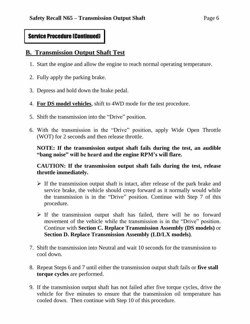
24. Carefully lower the transmission
assembly from the vehicle
(Figure 7).
25. Replace any broken electrical
wire harness clips.
26. Replace the transmission oil
heater O-rings (Figure 8).
NOTE: Each aluminum fittings
has two O-rings. Pull the
aluminum fittings out of the oil
heater body to replace the
second O-ring.
Service Procedure (Continued)
Figure 7 – Lower/Raise Transmission
Figure 8 – Transmission Oil Heater O-Rings
TRANSMISSION
OIL HEATER
TRANSMISSION EXTENSION
HOUSING
TRANSMISSION
TRANSMISSION
JACK
TRANSMISSION OUTPUT SHAFT
RUBBER O-RINGS
ALUMINUM FITTINGS
TRANSMISSION
OIL HEATER

Safety Recall N65 – Transmission Output Shaft Page 12
27. With the help of a lifting device, remove and discard the original transmission
from the transmission jack.
28. With the help of a lifting device, place the new transmission onto the
transmission jack.
29. Raise the transmission into position (Figure 7).
30. Install the bellhousing bolts. Tighten the bolts to 41 ft. lbs. (55 N·m).
31. Connect and route the transmission electrical wiring.
32. Install the transmission oil heater. Tighten the bolts to 18 ft. lbs. (25 N·m).
33. Install the six torque converter-to-drive plate bolts. Tighten the bolts to 31 ft. lbs.
(42 N·m).
34. Install the starter motor. Tighten the starter motor bolts to 40 ft. lbs. (54 N·m).
35. Install the front axle-to-engine bracket (Figure 5). Tighten the bolts to
48 ft. lbs. (65 N·m).
36. Install the manual “Park” release cable.
37. Install the right side bellhousing dust shield.
38. Install the transmission oil cooler tube on the right side of the bellhousing
(Figure 6).
39. Install the coolant tube bracket bolts at the top of the bellhousing.
40. Connect the transmission vent hose.
41. Using a transmission jack, install the transfer case assembly to the back of the
transmission.
NOTE: Be sure to remove the broken transmission output shaft from the
transfer case input coupler.
Service Procedure (Continued)

Safety Recall N65 – Transmission Output Shaft Page 13
42. Install the transfer case-to-transmission extension housing nuts (Figure 4).
Tighten the nuts to 25 ft. lbs. (34 N·m).
43. Connect the transfer case vent hose at the transfer case housing.
44. Connect the transfer case electrical wiring.
45. Install the transmission mount and adapter bracket (Figure 3).
46. Install the transmission crossmember (Figure 1). Tighten the bolts to 48 ft. lbs.
(65 N·m).
47. Using new bolts, align the alignment marks and install the front propeller shaft.
Tighten the bolts to 85 ft. lbs. (115 N·m).
48. Using new bolts, align the alignment marks and install the rear propeller shaft
(Figure 2). Tighten the bolts to 85 ft. lbs. (115 N·m).
49. Install the exhaust system “Y” pipe (Figure 1).
50. Lower the vehicle from the hoist.
51. Connect the negative battery cable.
52. Continue with Section F. Check Transmission Fluid Level.
Service Procedure (Continued)

Safety Recall N65 – Transmission Output Shaft Page 14
D. Replace Transmission Assembly (LD / LX Models)
NOTE: The following procedure is required if the transmission output shaft
fractures per the test performed in Section B.
1. Disconnect the negative battery cable at the battery.
2. Use the following procedure to remove the entire exhaust system:
a. Disconnect the right and left upstream exhaust oxygen sensor electrical connectors.
b. Place the transmission in neutral.
c. Lift the vehicle on an appropriate hoist.
d. Disconnect the right and left downstream exhaust oxygen sensor electrical
connectors.
e. Remove and save the two tunnel reinforcement brackets (Figure 9).
Service Procedure (Continued)
Figure 9 – Exhaust System and Reinforcement Brackets
TUNNEL REINFORCEMENT
BRACKETS
LEFT CATALYTIC
CONVERTER PIPE
RIGHT CATALYTIC CONVERTER PIPE
EXHAUST PIPE BAND CLAMPS
EXHAUST “Y”
PIPE MUFFLER

Safety Recall N65 – Transmission Output Shaft Page 15
f. Loosen the two exhaust pipe
band clamps (Figure 9).
g. Support the exhaust system
with a transmission jack and
disconnect the exhaust rubber
hangers.
h. Separate the exhaust “Y” pipe
from the right and left catalytic
converter pipes (Figure 9).
i. Remove and save the right and
left chrome exhaust tips
(Figure 10).
j. Carefully lower the exhaust system.
k. Remove and save the right and left side catalytic converter.
3. Remove and save the engine splash shield.
4. Remove and save the rear propeller shaft center bearing heat shield.
5. Mark the rear propeller shaft
orientation to the transmission
flange and rear axle flange.
6. Remove and save the rear propeller
shaft assembly.
7. Secure the transmission to a
transmission jack and remove the
transmission aluminum
crossmember (Figure 11).
8. Mark the front propeller shaft
orientation to the transfer case
flange and front axle flange.
Service Procedure (Continued)
Figure 10 – Exhaust Tips
Figure 11 – Transmission Aluminum Crossmember
CHROME EXHAUST TIP
EXHAUST RESONATOR
ALUMINUM CROSSMEMBER
TRANSFER CASE

Safety Recall N65 – Transmission Output Shaft Page 16
9. Remove and save the front
propeller shaft.
10. Remove and save the starter
motor heat shield.
11. Remove and save the starter
motor assembly.
NOTE: Do not disconnect the
electrical connections from the
starter motor. Once the starter
motor is unbolted, set the
starter aside.
12. Remove and save the six torque converter-to-drive plate bolts.
13. Disconnect the manual “Park” release cable (Figure 12).
14. Disconnect the vent hose located at
the top of the transmission case.
15. Disconnect all electrical connectors
from the transmission.
16. Remove and save the transmission
bellhousing bolts.
17. Using Special Tool 9546,
disconnect the transmission oil
cooler tubes at the transmission
(Figure 13).
Service Procedure (Continued)
Figure 12 – Gear Shift Linkage
Figure 13 – Transmission Oil Cooler Tubes
TRANSMISSION SHIFT LEVER
GEAR SHIFT
CABLE BRACKET
MANUAL “PARK”
RELEASE CABLE
SPECIAL TOOL 9546
TRANSMISSION OIL
COOLER TUBES
Safety Recall N65 – Transmission Output Shaft Page 17
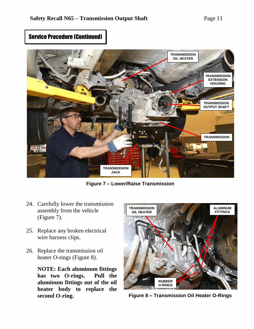
18. Carefully lower the transmission and
transfer case, as an assembly, from
the vehicle (Figure 14).
19. Remove and save the transmission
mount (Figure 14).
20. Remove and save the transfer case
mounting bolts.
21. Remove the transfer case from the
back of the transmission (Figure 15).
CAUTION: Keep the transfer
case in the upright position to
prevent fluid loss from the vent
tube.
Service Procedure (Continued)
Figure 14 – Transmission Assembly
Figure 15 – Remove/Install Transfer Case
TRANSMISSION MOUNT
TRANSMISSION JACK
TRANSFER
CASE
INPUT COUPLER
TRANSMISSION EXTENSION HOUSING
TRANSFER CASE

Safety Recall N65 – Transmission Output Shaft Page 18
22. With the help of a lifting device, remove the transmission from the transmission
jack.
23. With the help of a lifting device, place the new transmission assembly onto the
transmission jack.
24. Secure the new transmission to the transmission jack.
25. Install the original transfer case to the back of the new transmission. Tighten
the transfer case mounting bolts to 41 ft. lbs. (55 N·m).
NOTE: Be sure to remove the broken transmission output shaft from the
transfer case input coupler (Figure 15).
26. Apply a small amount of grease to the torque converter hub.
27. Raise the transmission into position and install the bellhousing bolts. Tighten
the bolts to 41 ft. lbs. (55 N·m).
28. Connect the transmission oil cooler tubes.
29. Install the six torque converter-to-drive plate bolts. Tighten the bolts to 31 ft.
lbs. (42 N·m).
30. Install the starter motor assembly. Tighten the starter motor bolts to 40 ft. lbs.
(54 N·m).
31. Install the starter heat shield. Tighten the small bolt to 22 ft. lbs. (30 N·m) and
the large bolt to 45 ft. lbs. (61 N·m).
32. Connect the vent hose to the top of the transmission case.
33. Connect the oxygen sensor wire clips to the transfer case.
34. Connect the transmission wiring harness to the transmission.
35. Connect the manual “Park” release cable to the transmission shift lever.
36. Install the front propeller shaft. Tighten the bolts to 48 ft. lbs. (64 N·m).
Service Procedure (Continued)
Safety Recall N65 – Transmission Output Shaft Page 19
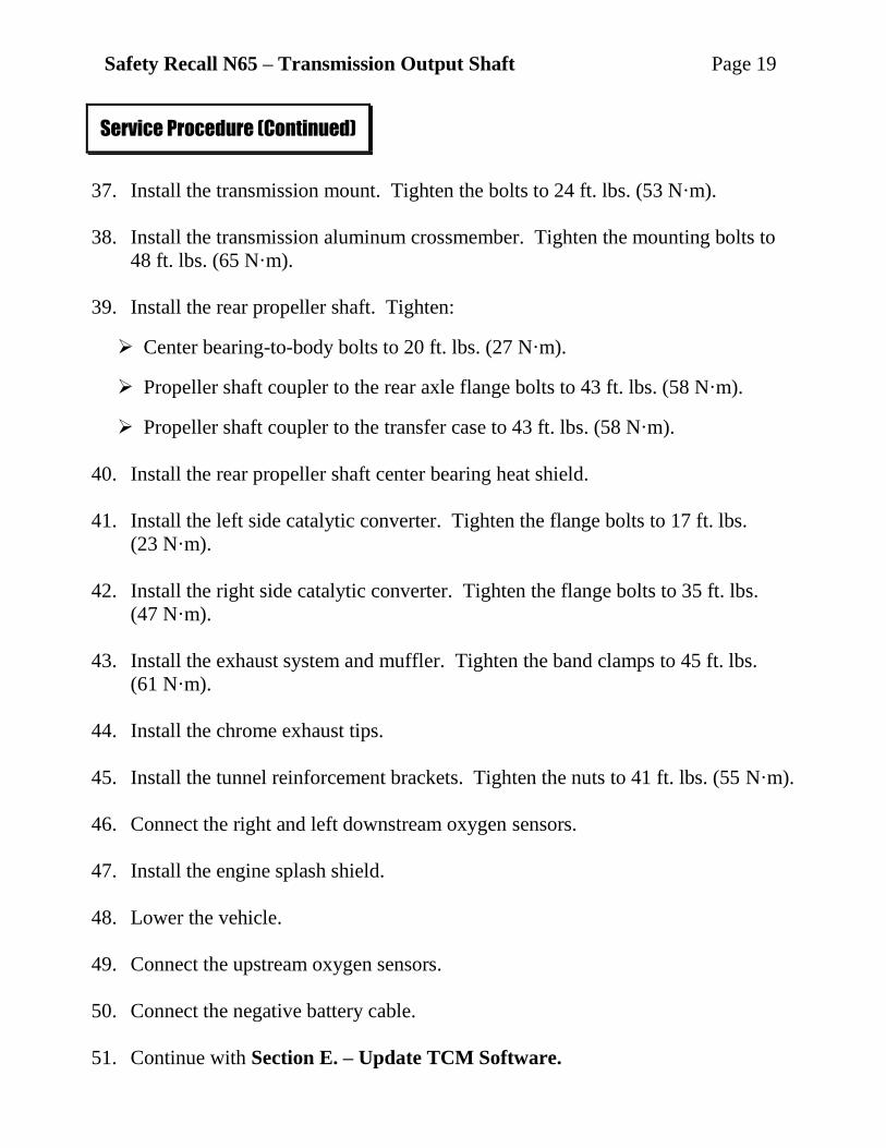
37. Install the transmission mount. Tighten the bolts to 24 ft. lbs. (53 N·m).
38. Install the transmission aluminum crossmember. Tighten the mounting bolts to
48 ft. lbs. (65 N·m).
39. Install the rear propeller shaft. Tighten:
Center bearing-to-body bolts to 20 ft. lbs. (27 N·m).
Propeller shaft coupler to the rear axle flange bolts to 43 ft. lbs. (58 N·m).
Propeller shaft coupler to the transfer case to 43 ft. lbs. (58 N·m).
40. Install the rear propeller shaft center bearing heat shield.
41. Install the left side catalytic converter. Tighten the flange bolts to 17 ft. lbs.
(23 N·m).
42. Install the right side catalytic converter. Tighten the flange bolts to 35 ft. lbs.
(47 N·m).
43. Install the exhaust system and muffler. Tighten the band clamps to 45 ft. lbs.
(61 N·m).
44. Install the chrome exhaust tips.
45. Install the tunnel reinforcement brackets. Tighten the nuts to 41 ft. lbs. (55 N·m).
46. Connect the right and left downstream oxygen sensors.
47. Install the engine splash shield.
48. Lower the vehicle.
49. Connect the upstream oxygen sensors.
50. Connect the negative battery cable.
51. Continue with Section E. – Update TCM Software.
Service Procedure (Continued)

Safety Recall N65 – Transmission Output Shaft Page 20
E. Update TCM Software (LX/LD Models Only)
CAUTION: If the test software remains in the vehicle’s TCM, the
transmission will not shift out of first gear and the check engine light will
remain illuminated.
1. Install a battery charger and verify that the charging rate provides 13.0 to 13.5
volts. Do not allow the charger to time out during the reprogramming process.
Set the battery charger timer (if so equipped) to continuous charge.
NOTE: Use an accurate stand-alone voltmeter. The battery charger volt
meter may not be sufficiently accurate. Voltages outside of the specified
range will cause an unsuccessful flash. If voltage reading is too high, apply
an electrical load by activating the park or headlamps and/or HVAC
blower motor to lower the voltage.
2. Connect the wiTECH VCI pod to the vehicle data link connector located to the
right of the hood release lever.
3. Place the ignition in the “RUN” position.
4. Open the wiTECH Diagnostic application.
5. Starting at the “Select Tool” screen, highlight the row/tool for the wiPOD
device you are using. Then select “Next” at bottom right side of the screen.
6. Enter your “User id” and “Password”, then select “Finish” at the bottom of the
screen.
7. From the “Vehicle View” screen, click on the TCM icon.
Service Procedure (Continued)
Safety Recall N65 – Transmission Output Shaft Page 21
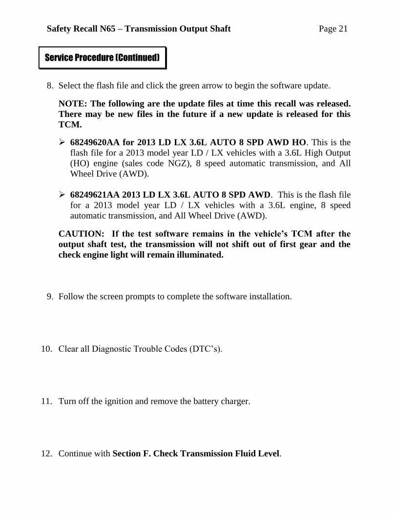
8. Select the flash file and click the green arrow to begin the software update.
NOTE: The following are the update files at time this recall was released.
There may be new files in the future if a new update is released for this
TCM.
68249620AA for 2013 LD LX 3.6L AUTO 8 SPD AWD HO. This is the
flash file for a 2013 model year LD / LX vehicles with a 3.6L High Output
(HO) engine (sales code NGZ), 8 speed automatic transmission, and All
Wheel Drive (AWD).
68249621AA 2013 LD LX 3.6L AUTO 8 SPD AWD. This is the flash file
for a 2013 model year LD / LX vehicles with a 3.6L engine, 8 speed
automatic transmission, and All Wheel Drive (AWD).
CAUTION: If the test software remains in the vehicle’s TCM after the
output shaft test, the transmission will not shift out of first gear and the
check engine light will remain illuminated.
9. Follow the screen prompts to complete the software installation.
10. Clear all Diagnostic Trouble Codes (DTC’s).
11. Turn off the ignition and remove the battery charger.
12. Continue with Section F. Check Transmission Fluid Level.
Service Procedure (Continued)

Safety Recall N65 – Transmission Output Shaft Page 22
F. Check Transmission Fluid Level (All Models)
WARNING: THERE IS A RISK OF ACCIDENT FROM VEHICLE
MOVING WHEN THE ENGINE IS RUNNING. SECURE VEHICLE TO
PREVENT IT FROM MOVING. THERE IS A RISK OF INJURY FROM
CONTUSIONS AND BURNS IF YOU INSERT YOUR HANDS INTO THE
ENGINE WHEN IT IS RUNNING. DO NOT TOUCH HOT OR ROTATING
PARTS. WEAR PROPERLY FITTED WORK CLOTHES.
CAUTION: A unique transmission fluid has been developed for this
transmission. This unique transmission fluid is NOT compatible with ATF+4
or any other current Chrysler transmission fluid.
1. Raise and support the vehicle on a level hoist.
2. Start the engine. The engine must continue to run through step 16.
3. Using a scan tool or the vehicle information center, verify that the transmission
fluid temperature is below 86°F (30°C).
4. Disable traction control (ESC).
5. Remove the fill plug from the right rear of the transmission case.
6. Add transmission fluid until it trickles from the fill opening.
7. Install the fill plug.
8. Lower the vehicle for access to inside of the vehicle, leaving the tires at least 8
inches off the ground.
Service Procedure (Continued)

Safety Recall N65 – Transmission Output Shaft Page 23
9. With the brakes applied, place the transmission in Reverse and hold for 5
seconds.
10. Place the transmission in Drive and hold for 5 seconds.
11. Release the brakes, slowly accelerate to 2nd gear and hold for 5 seconds.
12. Apply the brakes and place the transmission in Neutral.
13. Raise the engine speed to 2000 RPM for 5 seconds.
14. Return the engine to idle and place the transmission in “Park.”
NOTE: A full transmission will have fluid at the fill hole with the
transmission between 30°C (86°F) and 50°C (122°F). Do not over fill.
15. Remove the fill plug and allow excess transmission fluid to drain from fill hole
or add transmission fluid as necessary.
16. Install the transmission fill plug.
17. Using a scan tool, clear any DTCs.
18. Turn engine off.
19. Continue with Section G. Perform Transmission TCM Adaptation
Procedure.
Service Procedure (Continued)

Safety Recall N65 – Transmission Output Shaft Page 24
G. Perform Transmission TCM Adaptation Procedure (All Models)
The initial clutch filling pressure and fill times are set at the factory. When a
transmission assembly is replaced, the adaptation values must be relearned.
The two procedures to relearn these values are called Fast Filling Adaptation and
Standard Clutch Filling Adaptation. Failure to perform these procedures could
cause shift quality issues.
WARNING: An assistant will be required to drive the vehicle while the
technician watch the wiTECH screen. DO NOT drive the vehicle and attempt
to watch the wiTECH screen at the same time. Doing so creates an unsafe
driving situation.
Fast Filling Adaptation Procedure
CAUTION: Perform this procedure on a smooth road surface. The TCM or
TCMA will abort the adaptation process if it senses rough road conditions.
The road should be clear of traffic due to the start, stop, and slow vehicle
speeds required during this procedure.
1. With the Scan Tool, erase DTCs.
2. Setup the scan tool to display the Transmission Oil Temperature, Torque,
Turbine (Input) Speed Sensor rpm, and Clutch ‘X’ - Filling Counter for each
clutch.
3. Drive the vehicle until the Transmission Oil Temperature is above 86° F (30° C).
4. Stop the vehicle.
Service Procedure (Continued)

Safety Recall N65 – Transmission Output Shaft Page 25
5. Drive the vehicle to perform upshifts for all gears under the following
conditions:
Light to medium throttle position
Turbine (Input) Speed between 1,250 - 2,000 rpm
Torque between 74 ft. lbs. and 111 ft. lbs. (100 N·m and 150 N·m).
6. Release the throttle (0% position) to coast and allow a 6-5 down-shift.
7. Repeat Steps 4 - 6 until the Filling Counters for each clutch displays 10 counts.
NOTE: The tables below may be used as an alternate reference for the
optimal conditions required to learn the Fast Filling Adaptations.
Fast Filling Adaptation Conditions Table
Conditions Where Fast Filling Adaptations Occur
Condition Transmission Temperature Range
Torque N·m (ft. lbs.) Range Input Speed (rpm) Range
Upshifts Between 86°F and
212°F (30°C and 100°C) Between 74 ft. lbs. and 111 ft. lbs.
(100 N·m and 150 N·m) Between 1250 and 2000 rpm
6-5 Downshifts for B Clutch
Between 86°F and 212°F (30°C and 100°C)
Between negative (-) 44 ft. lbs. and negative (-) 30 ft. lbs. (negative (-) 60 N·m and negative (-) 40 N·m)
Between 750 and 1100 rpm
Clutch vs Shift Table
Shifts Where Each Clutch Will Fast Adapt
A Clutch B Clutch C Clutch D Clutch E Clutch
Shift 6 - 7 6 - 5 2 - 3 and 4 - 5 3 - 4 1 - 2 and 5 - 6
Optimal conditions
under which adaptation
learning occurs.
Best performed at highway speeds in
excess of 50 mph (80 kph).
Coasting with throttle
at 0% position.
Best performed at light to
medium-throttle - normal vehicle
launch.
Best performed at light to
medium-throttle - normal vehicle
launch.
Best performed at light to
medium-throttle - normal vehicle
launch.
8. Continue with the Standard Clutch Filling Adaptation Procedure.
Service Procedure (Continued)

Safety Recall N65 – Transmission Output Shaft Page 26
Standard Clutch Filling Adaptation Procedure
NOTE: Perform this procedure on a smooth road surface. The TCM or
TCMA will abort the adaptation process if it senses rough road conditions.
The road should be clear of traffic due to the start, stop, and slow vehicle
speeds required during the procedure.
NOTE: The TCM learns the Standard Clutch Filling Adaptation values when
the applicable clutch is not applied.
WARNING: An assistant will be required to drive the vehicle while the
technician watch the wiTECH screen. DO NOT drive the vehicle and attempt
to watch the wiTECH screen at the same time. Doing so creates an unsafe
driving situation.
1. With the Scan Tool, erase DTCs.
2. Setup the scan tool to display the Transmission Oil Temperature, Torque,
Turbine (Input) Speed Sensor rpm, and Clutch ‘X’ - Fast Filling Counter for
each clutch.
3. Drive the vehicle until the Transmission Oil Temperature is above 122° F (50° C).
NOTE: Adaptation learning will be aborted if the Transmission Oil
Temperature is above 212° F (100° C).
4. Stop the vehicle.
5. Drive the vehicle using the paddle shifters or Gear +/- buttons on the steering
wheel in order to hold the transmission in the desired gear.
NOTE: First and second gears do not require a Standard Clutch Filling
Adaptation procedure
NOTE: If attempting to resolve a specific shift quality issue, use the Gear
vs. Clutch Table below to see which clutches require further adaptation.
For instance, if a rough 2-1 downshift is noted, note that clutch C and
clutch E are applying and releasing. Then use the Clutch vs. Shift Table
above to note that clutch C and clutch E require the adaptation procedure
performed in 4th and 7th gear.
Service Procedure (Continued)

Safety Recall N65 – Transmission Output Shaft Page 27
6. In 3rd gear, drive the vehicle within the following conditions until the Clutch
D - Fast Filling Counter increments by one count:
Vehicle speed between 20 - 35 mph (32 - 56 kph).
Turbine (Input) speed between 950 - 1750 rpm
Torque between 18 ft. lbs. - 133 ft. lbs. (25 N·m - 180 N·m).
7. In fourth gear, drive the vehicle within the following conditions until the Clutch
C - Fast Filling Counter increments by one count:
Vehicle speed between 20 - 35 mph (32 - 56 kph).
Turbine (Input) speed between 950 - 1750 rpm
Torque between 18 ft. lbs. – 89 ft. lbs. (25 N·m - 120 N·m).
NOTE: Fifth gear does not require a Standard Clutch Filling Adaptation
procedure.
8. In sixth gear, drive the vehicle within the following conditions until the Clutch
A - Fast Filling Counter increments by one count:
Vehicle speed between 45 - 50 mph (73 - 81 kph).
Turbine (Input) speed between 950 - 1750 rpm
Torque between 37 ft. lbs. – 89 ft. lbs. (50 N·m - 120 N·m).
9. In seventh gear, drive the vehicle within the following conditions until the
Clutch B- Filling Counter and Clutch E Fast Filling Counter each increment by
one count:
Vehicle speed between 45 - 50 mph (73 - 81 kph).
Turbine (Input) speed between 950 - 1750 rpm
Torque between 37 ft. lbs. – 89 ft. lbs. (50 N·m - 120 N·m).
Service Procedure (Continued)

Safety Recall N65 – Transmission Output Shaft Page 28
NOTE: The Standard Clutch Filling Adaptation Conditions Table below may
be used as an alternate reference for the optimal conditions required to learn
the Standard Clutch Filling Adaptations.
Standard Clutch Filling Adaptation Conditions Table
Steady State Gears And Conditions Where Each Clutch Will Adapt
Clutch Gear Optimal Vehicle Speed
Range
Input Speed (rpm) Range
Torque Ft. Lbs. (N.m) Range
Transmission Temperature Range
A Clutch
6th 45-50 mph (73-81 kph)
Between 950 and 1750 rpm
Between 37 ft. lbs. and 89 ft. lbs. (50 N·m and
120 N·m)
Between 122°F and 212°F (50°C and 100°C)
B Clutch
7th 45-50 mph (73-81 kph)
Between 950 and 1750 rpm
Between 37 ft. lbs. and 89 ft. lbs. (50 N·m and
120 N·m)
Between 122°F and 212°F (50°C and 100°C)
C Clutch
4th 20-35 mph (32-56 kph)
Between 950 and 1750 rpm
Between 18 ft. lbs. and 89 ft. lbs. (25 N·m and
120 N·m)
Between 122°F and 212°F (50°C and 100°C)
D Clutch
3rd 20-35 mph (32-56 kph)
Between 950 and 1750 rpm
Between 18 ft. lbs. and 89 ft. lbs. (25 N·m and
120 N·m)
Between 122°F and 212°F (50°C and 100°C)
E Clutch
7th 45-50 mph (73-81 kph)
Between 950 and 1750 rpm
Between 37 ft. lbs. and 89 ft. lbs. (50 N·m and
120 N·m)
Between 122°F and 212°F (50°C and 100°C)
10. Perform steps 4-9 until the Fast Filling Counters for each clutch has
incriminated by at least five counts.
11. Evaluate shift performance for all gears. If the shift quality for any gear is
insufficient, execute the appropriate driving conditions until shift quality
improves. Incrementing the Fast Filling Counters by 12 counts for each clutch
may be necessary to properly learn the adaptation values.
Service Procedure (Continued)

Safety Recall N65 – Transmission Output Shaft Page 29
NOTE: The following table can be used to determine which clutches are
involved in a specific up-shift or down-shift quality issue. “X” indicates when
a clutch is applied. The Standard Clutch Filling Adaptation learning occurs
when the applicable clutch is not applied and the transmission is in a steady
state (not shifting).
Gear vs Clutch Table
Gear Clutch A Clutch B Clutch C Clutch D Clutch E
1st X X X
2nd X X
X
3rd
X X
X
4th
X
X X
5th
X X X
6th
X X X
7th X
X X
8th X
X X
Reverse X X
X
NOTE: Read the information below for details regarding this procedure.
Reading Clutch Adaptation Data The Clutch Packs will each have 4 scan tool data labels to observe under the TCM
section. Using Clutch A as an example, the data labels are:
Clutch A- Fast Filling Counter: This data label displays the number of Clutch
Filling Pressure adaptations that have been performed. These adaptations are the
first learned values on a new transmission or after clutch adaptation values are
reset. You will need to allow 5 to 12 fast filling counts per clutch to properly learn
the clutch adaptations. If the shift quality is sufficient after 5 counts, no further
adaptation learns for that clutch are necessary.
Clutch A- Filling Counter: This data label displays the number of Clutch Filling
Time adaptations that have been performed. You will need to allow 5 to 12 filling
counts per clutch to properly learn the clutch adaptations. If the shift quality is
sufficient after 5 counts, no further adaptation learns for that clutch are necessary.
Service Procedure (Continued)

Safety Recall N65 – Transmission Output Shaft Page 30
Clutch A- Filling Pressure: This data label displays the clutch filling pressure
value that is learned during the TCM Adaptation procedure. The TCM adaptation
software will increase or decrease the clutch fluid filling pressure to improve shift
performance. The clutch Filling Pressure value will change over the life of the
transmission based first on initial transmission build variation and then due to
normal clutch wear.
Clutch A- Filling Time: This data label displays the clutch filling time value that
is learned during the TCM Adaptation procedure. The TCM adaptation software
will increase or decrease the Clutch Filling Time to improve shift performance.
The clutch Filling Time value will change over the life of the transmission based
first on initial transmission build variation and then due to normal clutch wear.
This recall is subject to the State of California Registration Renewal/Emissions
Recall Enforcement Program. Complete a Vehicle Emission Recall Proof of
Correction Form (Form No. 81-016-1053) and supply it to vehicle owners
residing in the state of California for proof that this recall has been performed
when they renew the vehicle registration.
Service Procedure (Continued)
Complete Proof of Correction Form for California Residents
Safety Recall N65 – Transmission Output Shaft Page 31
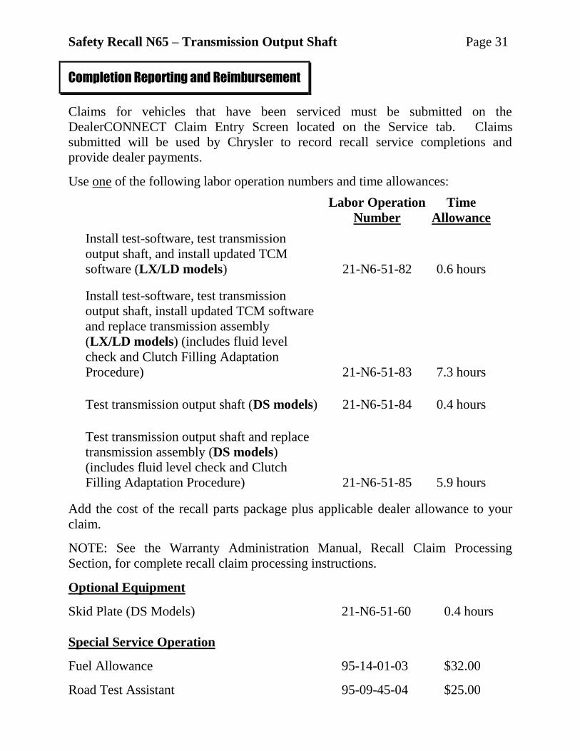
Claims for vehicles that have been serviced must be submitted on the
DealerCONNECT Claim Entry Screen located on the Service tab. Claims
submitted will be used by Chrysler to record recall service completions and
provide dealer payments.
Use one of the following labor operation numbers and time allowances:
Labor Operation Time
Number Allowance
Install test-software, test transmission
output shaft, and install updated TCM
software (LX/LD models) 21-N6-51-82 0.6 hours
Install test-software, test transmission
output shaft, install updated TCM software
and replace transmission assembly
(LX/LD models) (includes fluid level
check and Clutch Filling Adaptation
Procedure) 21-N6-51-83 7.3 hours
Test transmission output shaft (DS models) 21-N6-51-84 0.4 hours
Test transmission output shaft and replace
transmission assembly (DS models)
(includes fluid level check and Clutch
Filling Adaptation Procedure) 21-N6-51-85 5.9 hours
Add the cost of the recall parts package plus applicable dealer allowance to your
claim.
NOTE: See the Warranty Administration Manual, Recall Claim Processing
Section, for complete recall claim processing instructions.
Optional Equipment
Skid Plate (DS Models) 21-N6-51-60 0.4 hours
Special Service Operation
Fuel Allowance 95-14-01-03 $32.00
Road Test Assistant 95-09-45-04 $25.00
Completion Reporting and Reimbursement

Safety Recall N65 – Transmission Output Shaft Page 32
To view this notification on DealerCONNECT, select “Global Recall System” on
the Service tab, then click on the description of this notification.
All involved vehicle owners known to Chrysler are being notified of the service
requirement by first class mail. They are requested to schedule appointments for this
service with their dealers. A generic copy of the owner letter is attached.
Enclosed with each owner letter is an Owner Notification postcard to allow owners
to update our records if applicable.
All involved vehicles have been entered into the DealerCONNECT Global Recall
System (GRS) and Vehicle Information Plus (VIP) for dealer inquiry as needed. GRS provides involved dealers with an updated VIN list of their incomplete
vehicles. The owner’s name, address and phone number are listed if known.
Completed vehicles are removed from GRS within several days of repair claim
submission.
To use this system, click on the “Service” tab and then click on “Global Recall
System.” Your dealer’s VIN list for each recall displayed can be sorted by: those
vehicles that were unsold at recall launch, those with a phone number, city, zip
code, or VIN sequence.
Dealers must perform this repair on all unsold vehicles before retail delivery.
Dealers should also use the VIN list to follow up with all owners to schedule
appointments for this repair.
Recall VIN lists may contain confidential, restricted owner name and address information that
was obtained from the Department of Motor Vehicles of various states. Use of this information
is permitted for this recall only and is strictly prohibited from all other use.
Dealer Notification
Owner Notification and Service Scheduling
Vehicle Lists, Global Recall System, VIP and Dealer Follow Up

Safety Recall N65 – Transmission Output Shaft Page 33
If you have any questions or need assistance in completing this action, please
contact your Service and Parts District Manager.
Customer Services / Field Operations
Chrysler Group LLC
Additional Information