safety of life at sea, 1974 (solas) - ulisboa · safety of life at sea, 1974 (solas) prof. manuel...
TRANSCRIPT

1
Safety of Life at Sea, 1974 (SOLAS)
Prof. Manuel Ventura
Ship Design I
MSc in Naval Architecture and Marine Engineering
M.Ventura SOLAS 2
SOLAS – Historical Background
• Convention, 1974• Protocol, 1978
– Amendments, 1983– Amendments, 1988
• Protocol, 1988– Amendments, 1991– Amendments, 1992– Amendments, 1994– Amendments, 1995– Amendments, 1996– Amendments, 1997– Amendments, 1998– Amendments, 1999– Amendments, 2000– Amendments, 2001– Amendments, 2002– Amendments, 2003– Amendments, 2004– Amendments, 2005
• The 1st Convention was approved in 1914 in the following of the TITANIC.
• The 2nd was in 1929
• The 3rd was in 1948
• The 4th was in 1960, and it was the first after the creation of IMO
International Convention for the Safety of Life at Sea

2
M.Ventura SOLAS 3
Safety of Life at Sea (SOLAS)
ContentsChapter I General ProvisionsChapter II-1. Construction – Subdivision and Stability, Machinery and
Electrical InstallationsChapter II-2. Fire Protection, Fire Detection and Fire Extinction
Part A. GeneralPart B. Passenger ShipsPart C. Cargo ShipsPart D. Tankers
DeterminesMinimum standards for building, outfitting and operating ships, compatible to their safety.
M.Ventura SOLAS 4
Safety of Life at Sea (SOLAS)
Contents (cont.)Chapter III. Lifesaving Appliances and arrangementsChapter IV. Radio communicationsChapter V. Safety in NavigationChapter VI. Carriage of CargoesChapter VII Carriage of Dangerous Goods
Part A Carriage of Dangerous Goods in Packaged FormPart A-1 Carriage of Dangerous Goods in Solid Form in BulkPart B Carriage de Liquid Chemicals in BulkPart C Carriage of Liquefied Gases in BulkPart D Carriage of Packaged Irradiated Nuclear Fuel or
Radioactive WastesChapter VIII Nuclear Ships

3
M.Ventura SOLAS 5
Safety of Life at Sea (SOLAS)
Contents (concl.)Chapter IX Management for the Safe Operation of ShipsChapter X Safety Measures for High-Speed Craft Chapter XI-1 Special Measures to Enhance Maritime Safety Chapter XI-2 Special Measures to Enhance Maritime SecurityChapter XII Additional Safety Measures for Bulk Carriers
Chapt. IX, X, XI – Amendments of 1994
M.Ventura SOLAS 6
Safety of Life at Sea (SOLAS)
Application• Ships engaged in international voyages
Exceptions• War ships• Cargo ships with GT < 500• Ships not propelled by mechanical means• Wooden ships of primitive build• Pleasure yachts not engaged in trade• Fishing vessels

4
Chapter II-1. Construction - Subdivision and Stability, Machinery and Electrical
Installations
M.Ventura SOLAS 8
Some Definitions
• Subdivision Length (Ls) - is the greatest projected moulded length of that part of the ship at or below deck or decks limiting the vertical extent of flooding with the ship at the deepest subdivision draught
• Breadth – is the greatest moulded breadth of the ship at or below the deepest subdivision draught
• Draught - is the vertical distance from the keel line at mid-length to the waterline in question.
• Deepest subdivision draught - is the waterline which corresponds to the summer load line draught of the ship.
• Bulkhead Deck– In a passenger ship means the uppermost deck at any point in the
subdivision length (Ls) to which the main bulkheads and the ship’s shell are carried watertight and the lowermost deck from which passenger and crew evacuation will not be impeded by water in any stage of flooding for damage cases. The bulkhead deck may be a stepped deck.
– In a cargo ship the freeboard deck may be taken as the bulkhead deck.
5
M.Ventura SOLAS 11
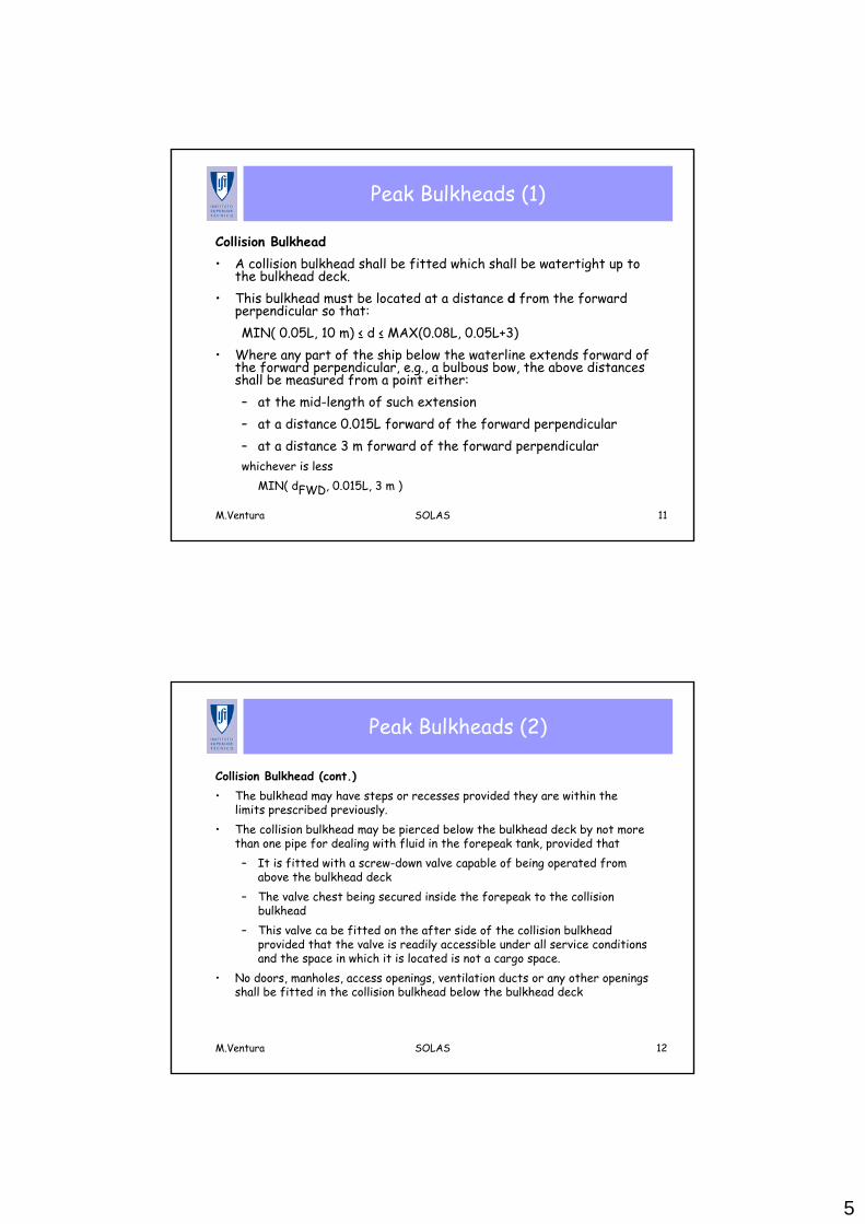
Peak Bulkheads (1)
Collision Bulkhead• A collision bulkhead shall be fitted which shall be watertight up to
the bulkhead deck.• This bulkhead must be located at a distance d from the forward
perpendicular so that:MIN( 0.05L, 10 m) ≤ d ≤ MAX(0.08L, 0.05L+3)
• Where any part of the ship below the waterline extends forward of the forward perpendicular, e.g., a bulbous bow, the above distances shall be measured from a point either:– at the mid-length of such extension– at a distance 0.015L forward of the forward perpendicular– at a distance 3 m forward of the forward perpendicularwhichever is less
MIN( dFWD, 0.015L, 3 m )
M.Ventura SOLAS 12
Peak Bulkheads (2)
Collision Bulkhead (cont.)• The bulkhead may have steps or recesses provided they are within the
limits prescribed previously.• The collision bulkhead may be pierced below the bulkhead deck by not more
than one pipe for dealing with fluid in the forepeak tank, provided that– It is fitted with a screw-down valve capable of being operated from
above the bulkhead deck – The valve chest being secured inside the forepeak to the collision
bulkhead– This valve ca be fitted on the after side of the collision bulkhead
provided that the valve is readily accessible under all service conditions and the space in which it is located is not a cargo space.
• No doors, manholes, access openings, ventilation ducts or any other openings shall be fitted in the collision bulkhead below the bulkhead deck
6
M.Ventura SOLAS 13
Machinery Spaces and Stern Tubes
Machinery Spaces• Bulkheads shall be fitted separating the machinery space from cargo and
accommodation spaces forward and aft and made watertight up to the bulkhead deck.
• In passenger ships an after peak bulkhead shall also be fitted and made watertight up to the bulkhead deck.
• The after peak bulkhead may, however, be stepped below the bulkhead deck, provided the degree of safety of the ship as regards subdivision is not thereby diminished..
Stern Tubes• In all cases stern tubes shall be enclosed in watertight spaces of moderate
volume. • In passenger ships the stern gland shall be situated in a watertight shaft
tunnel or other watertight space separate from the stern tube compartment and of such volume that, if flooded by leakage through the stern gland, the bulkhead deck will not be immersed.
M.Ventura SOLAS 14
Openings in the Shell Plating (1)
• The number of openings in the shell plating shall be reduced to the minimum
• No side scuttle shall be fitted in such a position that its sill is below a line drawn parallel to the bulkhead deck at side and having its lowest point at a distance MAX( 0.025 B, 500 mm) above the deepest subdivision draught.
• All side scuttles the sills of which are below – the bulkhead deck of passenger ships and– the freeboard deck of cargo ships,
shall be of such construction as will effectively prevent any person opening them without the consent of the master of the ship
Below the bulkhead deck of passenger ships and the freeboard deck of cargo ships:

7
M.Ventura SOLAS 15
Openings in the Shell Plating (2)
• Efficient hinged inside deadlights so arranged that they can be easily and effectively closed and secured watertight, shall be fitted to all side scuttles
• Except that – abaft 1/8 L from the forward perpendicular and– above a line drawn parallel to the bulkhead deck at side and– having its lowest point at a height of 3.7 m + 0.025 B above the
deepest subdivision draught
M.Ventura SOLAS 16
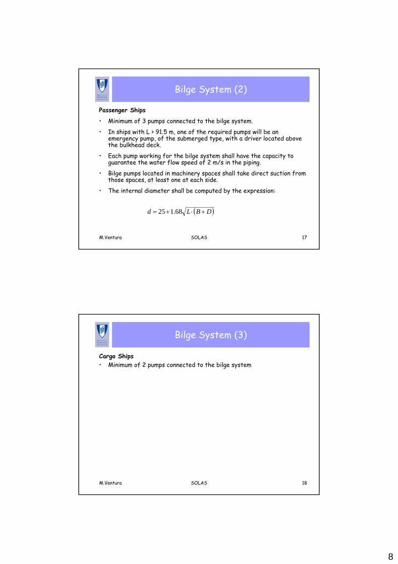
Bilge System (1)
Passenger and Cargo Ships
• The ship must have a an efficient bilge system capable of draining all the watertight compartments, other then tanks.
• Sanitary, ballast and general service pumps can be accepted as bilge pumps if they are connected to the bilge system.
8
M.Ventura SOLAS 17
Bilge System (2)
Passenger Ships
• Minimum of 3 pumps connected to the bilge system.
• In ships with L > 91.5 m, one of the required pumps will be an emergency pump, of the submerged type, with a driver located above the bulkhead deck.
• Each pump working for the bilge system shall have the capacity to guarantee the water flow speed of 2 m/s in the piping.
• Bilge pumps located in machinery spaces shall take direct suction from those spaces, at least one at each side.
• The internal diameter shall be computed by the expression:
( )DBLd +⋅+= 68.125
M.Ventura SOLAS 18
Bilge System (3)
Cargo Ships• Minimum of 2 pumps connected to the bilge system
9
M.Ventura SOLAS 19
Flooding Alarms in Passenger Ships
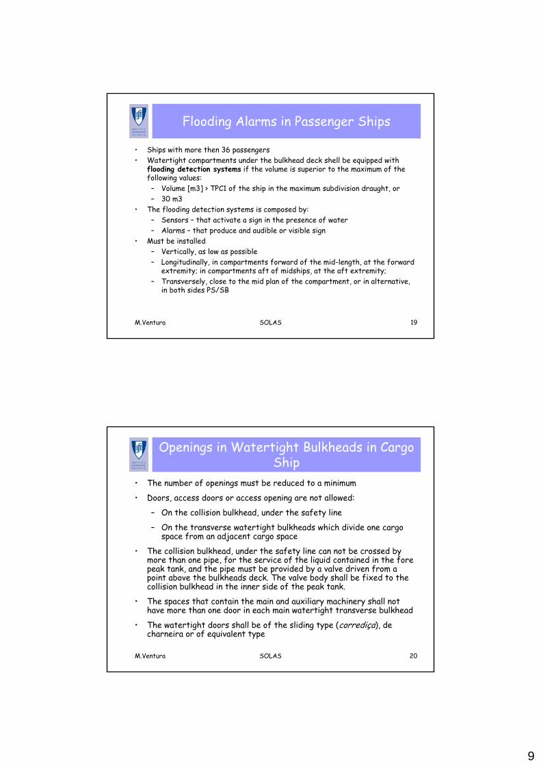
• Ships with more then 36 passengers• Watertight compartments under the bulkhead deck shell be equipped with
flooding detection systems if the volume is superior to the maximum of the following values:– Volume [m3] > TPC1 of the ship in the maximum subdivision draught, or– 30 m3
• The flooding detection systems is composed by:– Sensors – that activate a sign in the presence of water– Alarms – that produce and audible or visible sign
• Must be installed– Vertically, as low as possible– Longitudinally, in compartments forward of the mid-length, at the forward
extremity; in compartments aft of midships, at the aft extremity; – Transversely, close to the mid plan of the compartment, or in alternative,
in both sides PS/SB
M.Ventura SOLAS 20
Openings in Watertight Bulkheads in Cargo Ship
• The number of openings must be reduced to a minimum
• Doors, access doors or access opening are not allowed:
– On the collision bulkhead, under the safety line
– On the transverse watertight bulkheads which divide one cargo space from an adjacent cargo space
• The collision bulkhead, under the safety line can not be crossed by more than one pipe, for the service of the liquid contained in the fore peak tank, and the pipe must be provided by a valve driven from a point above the bulkheads deck. The valve body shall be fixed to the collision bulkhead in the inner side of the peak tank.
• The spaces that contain the main and auxiliary machinery shall not have more than one door in each main watertight transverse bulkhead
• The watertight doors shall be of the sliding type (corrediça), de charneira or of equivalent type

10
M.Ventura SOLAS 21
New Probabilistic Methods
• The damaged stability criteria from SOLAS are now based in probabilistic concepts rather then in the deterministic ones used previously
• These methods entry into force in January of 2009
Cases of de damaged survivability contribute to an index that can be used as a global measure of the capacity of survival
Determines a minimum GM that must be satisfied in all criteria, for every critical damage; the ship must have a GM superior to the minimum specified
All the damage cases can be examined; the probability of occurrence of the damage is based in statistical analysis of real accidents
Damages that exceed the specified limits are not taken into consideration
Global measure of the survivabilitySpecified a fixed standard damage
Probabilistic StandardDeterministic Standard
M.Ventura SOLAS 22
Subdivision and Damaged Stability in Cargo Ships (1)
Application• All cargo ships with LS > 100 m that are not covered by other
dispositions of IMO, namely:– Annex I of MARPOL 73/78– International Code for the Carriage of Chemicals in Bulk– International Code for the Carriage of Gas– Resolution A.469 (XIII) – Guidelines for the Design and Build of supply-
vessels for offshore– Resolution A.534 Code for the Safety of Special Ships– Damaged stability requirements from the Reg. 27 of International Load
Line Convention, 1966

11
M.Ventura SOLAS 23
Subdivision and Damaged Stability in Cargo Ships (2)
Definitions• Subdivision load line is a waterline used in determining the subdivision
of the ship.• Deepest subdivision load line is the subdivision load line which
corresponds to the summer draught to be assigned to the ship.• Partial load line is the light ship draught plus 60% of the difference
between the light ship draught and deepest subdivision load line.• Subdivision length of the ship (Ls) is the greatest projected moulded
length of that part of the ship at or below deck or decks limiting the vertical extent of flooding with the ship at the deepest subdivision load line.
• Breadth (B) is the greatest moulded breadth of the ship at or below the deepest subdivision load line.
• Draught (d) is the vertical distance from the moulded baseline at mid-length to the waterline in question.
M.Ventura SOLAS 24
Subdivision and Damaged Stability in Cargo Ships (3)
Required Subdivision Index (R)• The degree of subdivision to be provided shall be determined by the
required subdivision index R, as follows:
( ) 310009.0002.0 LsR ⋅+=
RA≥
The subdivision index computed for the ship shall comply to the condition

12
M.Ventura SOLAS 25
Subdivision and Damaged Stability in Cargo Ships (4)
Attained Subdivision Index (A)• The subdivision index of the ship shall be computed by the
expression:
∑ ⋅=n
iii spA
where:i - represents each compartment or group of compartments
under considerationpi - accounts for the probability that only the compartment or
group of compartments under consideration may be flooded, disregarding any horizontal subdivision
si - accounts for the probability of survival after flooding the compartment or group of compartments under consideration, including the effects of any horizontal subdivision.
M.Ventura SOLAS 26
Subdivision and Damaged Stability in Cargo Ships (5)
Calculation of the factor pi• The factor Pi is determined for each single compartment:• Where the compartment considered extends over the entire ship
length Ls 1=ip
• Where the aft limit of the compartment considered coincides withthe aft terminal:
qpaFpi +⋅⋅+= 5.0
• Where the forward limit of the compartment considered coincides with the forward terminal:
paFpi ⋅⋅+−= 5.01
• When both ends of the compartment considered are inside the aft and forward terminals of the ship length LS
papi ⋅=

13
M.Ventura SOLAS 27
Subdivision and Damaged Stability in Cargo Ships (6)
Notation• For the purpose of these calculations, the following notation is
applied:– x1 - the distance from the aft terminal of Ls to the foremost
portion of the aft end of the compartment being considered.– x2 - the distance from the aft terminal of Ls to the aftermost
portion of the forward end of the compartment being considered.
0/0/
1
12
212
21
1
<+=′≥−=′
−=
−+===
EpEJJEpEJJ
EEJ
EEELxE
LxE
SS
Jmax- The maximum nondimensional damage length
( )24.0.max48max
SLJ =
M.Ventura SOLAS 28
Subdivision and Damaged Stability in Cargo Ships (7)
a – The assumed distribution density of damage location along the ship’s length
( )2.1.max8.02.1 Ea ⋅+=
F -The assumed distribution function of damage location along the ship’s length.
( )aEF +⋅⋅+= 2.125.04.0
( )2max2
max1
4.0 JFq
JFp
⋅⋅=
⋅=
1/121
32
1/123
2
2
43
2
≥+−=
<−=
ypyyF
ypyyF
1/31
1/3
1
32
1
≥−=
<−=
ypyF
ypyyF
14
M.Ventura SOLAS 29
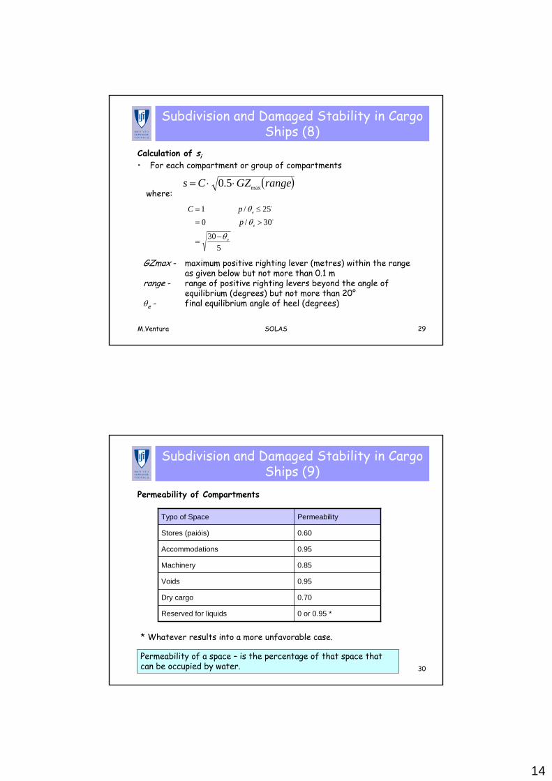
Subdivision and Damaged Stability in Cargo Ships (8)
Calculation of si• For each compartment or group of compartments
( )rangeGZCs max5.0 ⋅⋅=where:
530
30/025/1
e
e
e
ppC
θ
θθ
−=
>=
≤=
GZmax - maximum positive righting lever (metres) within the range as given below but not more than 0.1 m
range - range of positive righting levers beyond the angle of equilibrium (degrees) but not more than 20°
θe - final equilibrium angle of heel (degrees)
M.Ventura SOLAS 30
Subdivision and Damaged Stability in Cargo Ships (9)
Permeability of Compartments
* Whatever results into a more unfavorable case.
0 or 0.95 *Reserved for liquids
0.70Dry cargo
0.95Voids
0.85Machinery
0.95Accommodations
0.60Stores (paióis)
PermeabilityTypo of Space
Permeability of a space – is the percentage of that space that can be occupied by water.

15
M.Ventura SOLAS 31
Steering Gear (1)
• Every ship shall be provided with a main steering gear and an auxiliary steering gear
• Arranged that the failure of one of them will not render the other one inoperative
• The main steering gear and the rudder stock shall:
– Have adequate strength and be capable of steering the ship at the maximum service speed
– Capable of moving the rudder from 35° at one side to 35° on the other side with the ship at its deepest seagoing draught and running ahead at maximum ahead service speed
– On the same conditions, move the rudder from 35° at one side to 30° at the other side in less than 28 seconds
M.Ventura SOLAS 32
Steering Gear (2)
The auxiliary steering gear shell be designed to:
• Have adequate strength and be capable of steering the ship at a navigable speed and of being brought speedily into action in an emergency
• Capable of putting the rudder over from 15° on one side to 15° on the other side in not more than 60 s with the ship at its deepest seagoing draught and running ahead at one half of the maximum ahead service speed or 7 knots, whichever is the greater
16
M.Ventura SOLAS 33
Emergency Source of Electrical Power in Cargo Ships with GT ≥ 5000
• A self-contained emergency source of electrical power shall be provided• Located above the uppermost continuous deck and shall be readily accessible
from the open deck• Not to be located forward of the collision bulkhead• The electrical power available shall be sufficient to supply all those services
that are essential for safety in an emergency, such as:– Emergency lighting (for 18 h)– Fire detection and fire alarm systems– Navigation lights (for 18h)
• Energy supply for 6 hours• The emergency source can be
– Accumulator battery– Generator driven by driven by a suitable prime mover with an independent
supply of fuel
M.Ventura SOLAS 34
Emergency Source of Electrical Power in Cargo Ships with GT < 5000
• Must have an autonomous energy source located at satisfaction of the Administration
• Capable of lighting in the areas of stowage and launching of thelifeboats
• Energy supply for 3 hours

17
Stability of Ro/Ro Passenger Ships
M.Ventura SOLAS 37
Stability of RO/RO Passenger Ships
• The stability criteria applicable to Ro/Ro ferries has been under consideration since the accidents of the “Herald of Free Enterprise” (1987) and the “Estonia”(1994)
• SOLAS 90 (IMO SOLAS 1974 Convention as amended 1997)• MSC Circ.574 (1991) defined the simplified method based on the evaluation of
the Attained and Required subdivision index previously adopted in 1974 by the A.265 (VII)
• The latest IMO decisions after SOLAS 90 are contained in the resolutions:– MSC.14 (1995) - Regional agreement known as Stockholm Agreement
(deterministic method)– Resolution MSC.216(82) - Describes the new probabilistic method
applicable to passenger and cargo ships and replaces the MSC.47(66) that was only for cargo ships
– Resolution MSC.194(80) known as SOLAS 2009• The EU Directive 2003/25/CE adopted the Stockholm Agreement

18
M.Ventura SOLAS 38
Stockholm Agreement
• Agreement made in 1996 by 8 countries from North-Europe for damaged stability of passenger Ro/Ro ships
• Takes into consideration the effect of embarked water on the Ro/Ro deck for conditions with a significative wave height of 4 m (SOLAS 90 used 1.5 m)
• Applicable on the EU as follows– International voyages (SOLAS 90)– Domestic voyages (Directive 98/18 CE)
• The state member must determine and publish the significative wave heights in the regions crossed by Ro/Ro passenger ships operating on their port on a regular basis
• Its applicable to ALL the Ro/Ro passenger ships with regular service starting/ending in a port from a member state
M.Ventura SOLAS 39
Some Definitions (1)
• Significative Wave Height (HS) – mean value of the upper third of the wave heights measured during a determined time interval. These values are those which have a probability of being exceeded during a year ≤ 10%– State Members must determine and publish the wave heights of
their maritime zones– In Portugal this information is not yet available (Information from
IPTM on 200-06-26)
• Residual Freeboard (FR) – minimum distance measured in the vertical between the damaged ro/ro deck and the final floating line, without taking into consideration the accumulated water on the damaged deck

19
M.Ventura SOLAS 40
Some Definitions (2)
Damage Length
M.Ventura SOLAS 41
Some Definitions (3)
Measurement of Residual Freeboard

20
M.Ventura SOLAS 42
Height of Water on Deck
• Height of water on Ro/Ro deck:– FR ≥ 2.0 m => HW = 0 m– FR ≤ 0.3 m => HW = 0.5 m– 0.3 < FR < 2.0 m => HW linearly interpolated
M.Ventura SOLAS 43
Height of Water on Deck
• HS < 1.5 m => HW = 0 m• HS ≥ 4.0 m => HW measured according to the figure

21
M.Ventura SOLAS 44
Tank Equalization (1)
The time required for complete cross-flooding is defined on the Resolution A.265 (VIII)
The time required for bringing the ship from an angle of θ deg. (or the angle of margin line immersion) to an upright condition is
M.Ventura SOLAS 45
Tank Equalization (2)

22
M.Ventura SOLAS 46
SOLAS 2009
• Applicable to ships with keel laid after the 1st January 2009• Updated the probabilistic method to evaluate the Required and
Attained subdivision indexes, now mandatory for– Cargo ships– Passenger ships
M.Ventura SOLAS 47
References
• Papanikolaou, Apostolos and Vassalos, Dracos (2001),"Enhanced Safety Requirements for European Ro-Ro Passenger Ships - The Stockholm Agreement: Past, Present & Future", Proc. 2nd Int. Conf. on Safety of Maritime Transport, June 7-9, 2001, Chios, Greece.
• Directive 98/18 CE from the European Parliament and the Council,from 14 April 2003, relative to specific prescriptions for stability of Ro/Ro Passenger Ships
• A.265 (VIII) Regulations of Subdivision and Stability of Passenger Ships
• A.266 (VIII) Recommendation on a Standard Method for Establishing Compliance with the Requirements for Cross-Flooding Arrangements in Passenger Ships