safety manual sil3 - hauber-elektronik
TRANSCRIPT
English
Edition: 06/05/2015
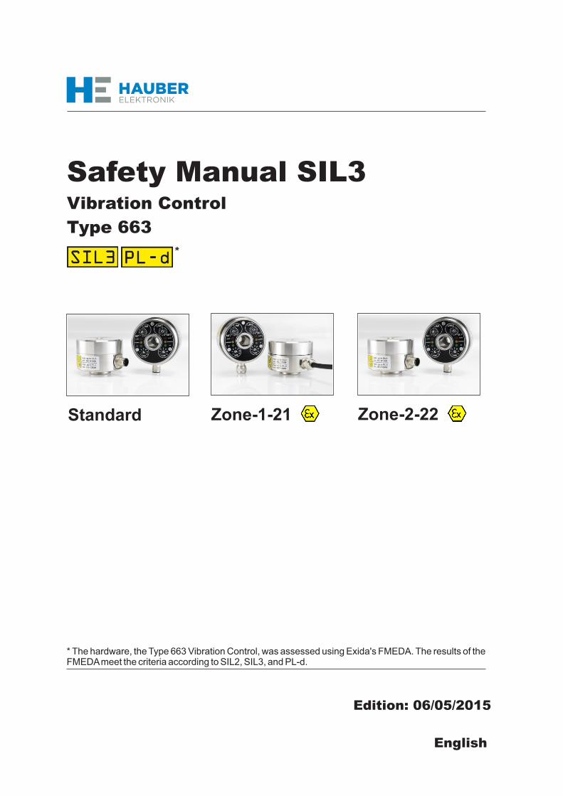
Standard Zone-1-21 Zone-2-22
Safety Manual SIL3Vibration Control
Type 663
* The hardware, the Type 663 Vibration Control, was assessed using Exida's FMEDA. The results of the FMEDA meet the criteria according to SIL2, SIL3, and PL-d.

HAUBER-Elektronik GmbH
All rights, including translation, reserved.Changes reserved.
Should any question arise, please contact:
HAUBER-Elektronik GmbHFabrikstraße 6D-72622 NürtingenGermanyPhone: +49 (0)7022 / 21750-0Fax: +49 (0)7022 / [email protected]
Safety Manual
Attention!Before commissioning the product, you must have read and
understood the safety manual and the operating manual in their entirety!
Vibration ControlType 663
StandardZone-1-21Zone-2-22

1. Scope ...................................................................................................4
2. Field of Application ...............................................................................4
3. SIL Conformity / Abbreviations, Terms................................................4
4. Relevant Standards ..............................................................................5
5. Safety Requirements ............................................................................5
6. Project Planning ...................................................................................6
7. Assembly and Installation.....................................................................7
8. Operation and Malfunction Response ..................................................7
9. Recurrent Testing [TProof] ...................................................................7
10. Useful Life...........................................................................................7
11. Safety Indicators............................................................................. 8-9
12. Management Summary .............................................................. 10-13
HAUBER-Elektronik GmbH
3
Table of Contents

HAUBER-Elektronik GmbH
4
1 Scope
The present Safety Manual of Vibration Control Type 663 is applicable for models Standard, Zone-1-21 and Zone-2-22. The functionality of these models is identical. In addition, models Zone-1-21 and Zone-2-22 have certifications and labellings allowing their operation in potentially explosive atmospheres.
Vibration Control Type 663 is used for measuring and monitoring the bearing vibration of machines as per DIN ISO 10816. Measurement parameter is the root mean square (rms) of the vibration velocity. The evaluation takes place in two channels independent from each other. The two relay outputs signal if the adjusted limit values are exceeded. This can be used to generate a pre- and a main alarm.In addition, Type 663 has an analogue current output. This delivers a direct current from 4...20 mA proportional to the vibration amplitude.
In determining the safety function, using the safety indicators in accordance with the standards mentioned under item 4 in the safety manual, the relay contacts of the Type 663 Vibration Control were explicitly evaluated and taken into account. The current output of 4...20 mA is not safety-relevant.
SIL Conformity is evidenced by the documents in Sect 13.
Further abbreviations and terms are named in IEC 61508-4.
2 Field of Application
3 SIL Conformity / Abbreviations, Terms
CAT Category according to EN ISO 13849-1:2008

5 Safety Requirements
Failure limits for a safety function, depending on the SIL class (IEC 61508-1, 7.6.2)
IEC 61508 Functional safety of electrical/electronic/programmable electronic safety-related systems
ISO 13849-1 Safety of machinery - Safety-related parts of control systems - Part 1: General principles for design (ISO 13849-1:2006); German version EN ISO 13849-1:2008
HAUBER-Elektronik GmbH
5
4 Relevant Standards
SafeFailure
Fraction
Hardware Fault Tolerance for safety related subsystems type A
(IEC 61508-2, 7.4.3)
SFF HFT = 0 HFT = 1 HFT = 2
< 60 % SIL1 SIL2 SIL3
60 % ... < 90 % SIL2 SIL3
90 % ... < 99 % SIL3
≥ 99 % SIL3
Safety Integrity Level Operating Mode with Low
Requirement Rate
Operating Mode with High
Requirement Rate
SIL PFDavg PFDavg
4 -5 -4≥10 ... < 10 -9 -8≥10 ... < 10
3-4 -3≥10 ... < 10 -8 -7≥10 ... < 10
2 -3 -2≥10 ... < 10 -7 -6≥10 ... < 10
1-2 -1≥10 ... < 10 -6 -5≥10 ... < 10

6 Project Planning
6
HAUBER-Elektronik GmbH
The safety function of this vibration control is the detection of exceeding vibration limits and the reporting of excessive vibration via relay contacts. The two limit values serve as pre- and a main alarm.
In determining the safety function using the safety indicators, according to the standards listed in item 4, the relay contacts of the vibration control were explicitly evaluated and/or taken into account.
Safety Function
Safe condition is ensured if one or more limit values are not exceeded. The owner has to adjust their plant-specific vibration limits. The adjustment procedure is described in the instruction manual.
Safe Condition
To evaluate the failure behaviour, the following definitions for device failure were considered:
Fail-Safe State As a response to a failure condition, the system changes into a safe condition (fail-safe state).
Safe Failure (λsd + λsu)There is a safe failure if the measuring system changes into the defined safe condition or into failure mode without a request by the process. Dangerous Failure (λdd + λdu)Generelly there is a dangerous failure if the measuring system enters a dangerous or non-functional condition.
Dangerous Detected Failure (λdd)There is a dangerous detected failure if the measuring system changes into the defined safe condition or into failure mode after a request by the process.
Dangerous Undetected Failure (λdu):There is a dangerous undetected failure if the measuring system neither changes into the defined safe condition nor into failure mode after a request by the process.
Definition of the failure mode:The failure mode corresponds to the alert condition of the relay.
Description of Failure Categories

HAUBER-Elektronik GmbH
7
According to IEC 61508-4, Sec. 3.5.8, TProof is defined as reccurent testing to detect failures in a safety-related system.
The recurrent function test is used to check the safety function and to uncover potential, unidentified errors.Therefore, check the device operability in reasonable intervals.It is the responsibility of the owner to choose the type of verification. The intervals depend on the device's expected frequency of utilisation. Use 1% of the expected utilisation as self-testing interval.Example:Assuming that the vibration control detects one critical error every 365 days, the testing interval should be 3...4 days.
The test needs to verify the proper safety function when all components interact. Name the testing methods and procedures used and specify their suitability level.Document the test. If the test is negative, shut down the entire vibration control and keep the process in its safe condition using other measures.
If using the self-check function provided by the vibration control, the vibration control itself can be used as an input unit in the CAT2 architecture category.
See the instruction manual, item 15, "Self-Check", for a general description and the functionality of the self-check.
Ensure to follow the assembly and installation instructions as per the instruction manual. As part of the commissioning procedure you need to test the safety function using the self-test function. To do so, adjust the limit values such that the safety function is triggered before any damage is caused to the machine.
Do not change the adjustable elements or device parameters during operation.If the adjustable elements or device parameters are changed during operation, the owner must guarantee the safety of the system!Potentially occurring errors are described in the error table of the instruction manual. If errors are detected, shut down the entire vibration control and keep the process in its safe condition using other measures. See the instruction manual for replacing the vibration control.
7 Assembly and Installation
8 Operation and Malfunction Response
9 Recurrent Testing [TProof]
10 Useful Life
The useful life of the measuring system is 10 years.

HAUBER-Elektronik GmbH
The failure rates of the electronic system, mechanical parts of the vibration control as well as the process connection have been determined by an FMEDA acc. to IEC 61508.The calculations are based on component-failure rates acc. to SN 29500.All numerical values refer to an average ambient temperature of 40° C during operation. For a higher average ambient temperature of 60° C, experience has shown that the failure rates should be multiplied by a factor of 2.5. A similar value applies if frequent temperature fluctuations can be expected (> 15° C a day) . The calculations are also based on the references in Section “Project Planning“.
11 Safety Indicators
8
2 The complete subsystem will need to be evaluated to determine the overall Safe Failure Fraction. The number listed
is for reference only. 3 SIL AC (architectural constraints) means that the calculated values are within the range for hardware architectural
constraints for the corresponding SIL but does not imply that all related IEC 61508 requirements are fulfilled.
PFD valuesAVG
T[Proof] = 1 year T[Proof] = 2 years T[Proof] = 5 years
AVG = 4,04E-05 PFDAVG = 7,56E-05 PFDAVG = 1,81E-04
Table 1: IEC 61508-2010 failure rates during normal operation with self-test
Failure category Failure rates (in FIT)
Fail Safe Detected ( SD) 0
Fail Safe Undetected (λSU) 75
Fail Dangerous Detected (λDD) 85
Fail Dangerous Detected (λDD) 64
Fail Annunciation Detected (λAD) 21
Fail Dangerous Undetected (λDU) 9
Fail Annunciation Undetected (λAU) 1
No effect 206
No part 39
Total failure rate (safety function) 169
SFF 2 94%
SIL AC 3 SIL3
PFH 9.0E-09 1/h
Safety metrics according to ISO 13849-1:
MTTFd (years) 1563
DC 90%
Category (CAT) CAT2
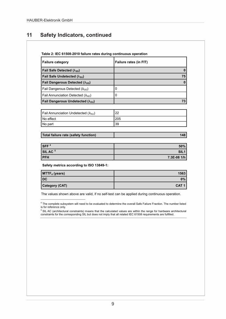
The user of the Vibration Control can initiate a self-test of the system, which can find several errors and check the basic safety function. During continuous operation, this self-test cannot be applied. The user of the system is responsible to apply the self-test in adequate intervals. If no self-test can be applied during continuous operation, the values according to Table 2 are valid.
λ
PFD
HAUBER-Elektronik GmbH
9
11 Safety Indicators, continued
Table 2: IEC 61508-2010 failure rates during continuous operation
Failure category Failure rates (in FIT)
Fail Safe Detected (λSD) 0
Fail Safe Undetected (λSU) 75
Fail Dangerous Detected (λDD) 0
Fail Dangerous Detected (λDD) 0
Fail Annunciation Detected (λAD) 0
Fail Dangerous Undetected (λDU) 73
Fail Annunciation Undetected (λAU) 22
No effect 205
No part 39
Total failure rate (safety function) 148
SFF 4 50%
SIL AC 5 SIL1
PFH 7.3E-08 1/h
Safety metrics according to ISO 13849-1:
MTTFd (years) 1563
DC 0%
Category (CAT) CAT 1
The values shown above are valid, if no self-test can be applied during continuous operation.
4 The complete subsystem will need to be evaluated to determine the overall Safe Failure Fraction. The number listed
is for reference only. 5 SIL AC (architectural constraints) means that the calculated values are within the range for hardware architectural
constraints for the corresponding SIL but does not imply that all related IEC 61508 requirements are fulfilled.

HAUBER-Elektronik GmbH
10
12 Management Summary
The document was prepared using best effort. The authors make no warranty of any kind and shall not be liable in any event for incidental or consequential damages in connection with the application of the document.
© All rights on the format of this technical report reserved.
Failure Modes, Effects and Diagnostic Analysis
Project:
Type 663 Vibration Control
Customer:
HAUBER-Elektronik GmbH Nürtingen Germany
Contract No.: Hauber Q11/09-058
Report No.: Hauber Q11/09-058 R001
Version V2, Revision R0; May 2012
Jan Hettenbach

HAUBER-Elektronik GmbH
11
GmbH Hauber Q11-09-058 R001 V2R0.doc; May 04, 2012 Page 2 of 4
Management Summary
This report summarizes the results of the hardware assessment carried out on the Type 663 Vibration Control.
The hardware assessment consists of a Failure Modes, Effects and Diagnostics Analysis (FMEDA). A FMEDA is one of the steps taken to achieve functional safety assessment of a device per IEC 61508. From the FMEDA, failure rates are determined and consequently the Safe Failure Fraction (SFF) is calculated for the device. For full assessment purposes all requirements of IEC 61508 must be considered.
For safety applications only the described device was considered. All other possible variants are not covered by this report.
The failure rates used in this analysis are the basic failure rates from the Siemens standard SN 29500. This failure rate database is specified in the safety requirements specification from HAUBER-Elektronik GmbH for the Vibration Control.
The listed SN29500 failure rates are valid for operating stress conditions typical of an industrial field environment with an average temperature over a long period of time of 40ºC. For a higher average temperature of 60°C, the failure rates should be multiplied with an experience based factor of 2.5. A similar multiplier should be used if frequent temperature fluctuation (daily fluctuation of > 15°C) must be assumed.
These failure rates are valid for the useful lifetime of the Vibration Control, see Appendix B.
The failure rates listed in this report do not include failures due to wear-out of any components. They reflect random failures and include failures due to external events, such as unexpected use, see section 4.2.3.
The Vibration Control is classified as Type A 1 elements according to IEC 61508, having a hardware fault tolerance of 0.
It can only be used for low demand mode applications. The failure rates
according to IEC 61508:2010 2nd edition for the Vibration Control (considering only the relay switching output being part of the safety function) are listed in the following table.
details see 7.4.4.1.2 of
© exida.comJan Hettenbach
1 Type A element: “Non-complex” element (all failure modes are well defined); for IEC 61508-2.

HAUBER-Elektronik GmbH
12
Table 1: IEC 61508-2010 failure rates during normal operation with self-test
Failure category Failure rates (in FIT)
Fail Safe Detected (λSD) 0
Fail Safe Undetected (λSU) 75
Fail Dangerous Detected (λDD) 85
Fail Dangerous Detected (λDD) 64
Fail Annunciation Detected (λAD) 21
Fail Dangerous Undetected (λDU) 9
Fail Annunciation Undetected (λAU) 1
No effect 206
No part 39
Total failure rate (safety function) 169
SFF 2 94%
SIL AC 3 SIL3
PFH 9.0E-09 1/h
Safety metrics according to ISO 13849-1:
MTTFd (years) 1563
DC 90%
Category (CAT) CAT2
Performance Level 9.0E-09 1/h
The user of the Vibration Control can initiate a self-test of the system, which can find several errors and check the basic safety function. During continuous operation, this self-test cannot be applied. The user of the system is responsible to apply the self-test in adequate intervals. If no self-test can be applied during continuous operation, the values according to Table 2 are valid.
© exida.com GmbH Hauber Q11-09-058 R001 V2R0.doc; May 04, 2012 Jan Hettenbach Page 3 of 4
2 The complete subsystem will need to be evaluated to determine the overall Safe Failure Fraction. The number listed is for reference only. 3 SIL AC (architectural constraints) means that the calculated values are within the range for hardware architectural constraints for the corresponding SIL but does not imply that all related IEC 61508 requirements are fulfilled.

13
HAUBER-Elektronik GmbH
© exida.com
GmbH Hauber Q11-09-058 R001 V2R0.doc; May 04, 2012 Jan Hettenbach Page 4 of 4
Table 2: IEC 61508-2010 failure rates during continuous operation
Failure category Failure rates (in FIT)
Fail Safe Detected (λSD) 0
Fail Safe Undetected (λSU) 75
Fail Dangerous Detected (λDD) 0
Fail Dangerous Detected (λDD) 0
Fail Annunciation Detected (λAD) 0
Fail Dangerous Undetected (λDU) 73
Fail Annunciation Undetected (λAU) 22
No effect 205
No part 39
Total failure rate (safety function) 148
SFF 4 50%
SIL AC 5 SIL1
PFH 7.3E-08 1/h
Safety metrics according to ISO 13849-1:
MTTFd (years) 1563
DC 0%
Category (CAT) CAT 1
Performance Level 7.3E-08 1/h
The values shown above are valid if no self-test can be applied during continuous operation.
4 The complete subsystem will need to be evaluated to determine the overall Safe Failure Fraction. The number listed
is for reference only. 5 SIL AC (architectural constraints) means that the calculated values are within the range for hardware architectural
constraints for the corresponding SIL but does not imply that all related IEC 61508 requirements are fulfilled.