safety instructions iwaki electromagnetic metering pump ... · iwaki electromagnetic metering pump...
TRANSCRIPT

2008 IWAKI CO., LTD.
IwakiElectromagnetic Metering PumpEHN-R (Standard)
Instruction manualThank you for choosing our product.
Please read through this instruction manual before use.
This instruction manual describes important precautions and instructions for the product. Always keep it on hand for quick reference.
Safety instructionsO
utlineInstallation
Operation
Maintenance
Specification

2 Order confirmation
1P423609
CAPACITYMAX.PRESSURE
STROKE RATEVOLTAGE
POWER CONSUMPTIONTHERMALLY PROTECTED
MODELMFG.No.
m / minMPaspm
V FREQUENCY 50/60 HzW
CURRENT A
IwakiMetering Pump
IWAKI CO.,LTD. TOKYO JAPAN
Back pressure valve
Check valve
Order confirmation
After unpacking, check the following points. Contact us or your nearest dealer if the delivery is imperfect.
a. Check if the delivery is as per order.Check the nameplate to see if the dis-charge capacity, discharge pressure and voltage are as per order.
b. Check if accessories are complete.• A check valve or a back pressure valve* The attached check valve and back pressure valve vary
with pump models. See page 86 for accessory list.
• A tube (3m)(ø4×ø9 or ø8×ø13 PVC braided tube)* ø4×ø9 or ø8×ø13 EVA tube is attached to the PP type.
*No tube is attached to the FC type.
*ø4×ø6 nylon tube is attached to the H type.
c. Check if the delivery is damaged or deformed.Check for transit damage and loose bolts.

3Contents
ContentsOrder confirmation ............................................................................................. 2
Safety instructions .......................................................................6
Warning ............................................................................................................. 7
Caution .............................................................................................................. 8
Precautions for use ........................................................................................10
Outline ......................................................................................... 12
Introduction .....................................................................................................12
Pump structure & Operating principle .........................................................12
Features .......................................................................................................13
Operational function ....................................................................................13
Part names.......................................................................................................16
Pump............................................................................................................16
Operational panel ........................................................................................17
Basic displays & Pump states ................................................................18
Identification codes ........................................................................................19
Pump/Drive units .........................................................................................19
Control unit ................................................................................................. 20
Installation ..................................................................................21
Pump mounting ...............................................................................................21
Pipework ......................................................................................................... 22
Tube connection ......................................................................................... 22
Check valve mounting .................................................................................24
Wiring .............................................................................................................. 26
Power supply/Earthing ................................................................................ 26
External input cable .................................................................................... 28

4 Contents
Operation .....................................................................................32
Before operation ............................................................................................ 32
Points to be checked .................................................................................. 32
Retightening of pump head fixing bolts ...................................................... 32
Degassing ................................................................................................... 33
EHN- [11•16•21] [VC•VH•PC•PH•PP] ................................................ 34
EHN- [11•21] [FC] and [31•36] [VC•VH•PC•PH•PP•FC] ........................................................ 36
Flow rate adjustment .................................................................................. 38
Stroke rate adjustment .......................................................................... 39
Stroke length adjustment........................................................................41
Before a long period of stoppage (One month or more) ..............................42
Operation programming ............................................................................... 43
Programming flow ....................................................................................... 44
Manual operation ........................................................................................ 46
EXT operation ..............................................................................................47
EXT mode ..............................................................................................47
EXT mode programming ....................................................................... 49
STOP function ............................................................................................ 58
STOP function programming ................................................................. 58
STOP function cancellation ................................................................... 60
Keypad lock ................................................................................................ 62
Maintenance ................................................................................64
Troubleshooting ............................................................................................. 65
Inspection ....................................................................................................... 67
Daily inspection ...........................................................................................67
Periodic inspection ......................................................................................67
Wear part replacement .................................................................................. 68
Wear part list ............................................................................................... 68
Before replacement .................................................................................... 69

5Contents
Valve set replacement ................................................................................ 69
Discharge valve set dismantlement/assembly ...................................... 69
Suction valve set dismantlement/assembly ...........................................72
Diaphragm replacement ..............................................................................73
Exploded view .................................................................................................76
Pump head, Drive unit & Control unit ..........................................................76
Pump head ................................................................................................. 77
EHN-[B11•B16•B21•C16•C21] [VC•VH•PC•PH] .................................... 77
EHN-[B31•C31•C36] [VC•VH•PC•PH] ...................................................78
EHN- PP .............................................................................................79
EHN- FC ............................................................................................ 80
EHN-[C31•C36] VH/PH-V ......................................................................81
Check valve (VC•VH•PC•PH) ..................................................................... 82
Specification/ Outer dimension ................................................................... 83
Specification ............................................................................................... 83
Pump unit .............................................................................................. 83
Control unit ............................................................................................ 85
Power cable ........................................................................................... 85
Pump colour .......................................................................................... 85
Accessories ................................................................................................ 86
Options ....................................................................................................... 86
Outer dimensions.........................................................................................87
EHN-[B11•B16•B21] [VC•VH•PC•PH•PP] ..............................................87
EHN-B31[VC•VH•PC•PH•PP] ................................................................87
EHN-[C16•C21] [VC•VH•PC•PH•PP] .................................................... 88
EHN-[C31•C36] [VC•VH•PC•PH•PP] .................................................... 88
EHN-[B11•B21] FC ................................................................................ 89
EHN-[C21] FC ....................................................................................... 89
EHN-[C31•C36] FC ............................................................................... 90

6
Read through this section before use. This section describes important information for you to prevent personal injury or property damage.
■ Pictorial indicationIn this instruction manual, the estimated risk of degree caused by incorrect use is ranked with the following pictorial indications. First, fully understand informa-tion on the pictorial indications.
Indicates mishandling could lead to a fatal or seri-ous injury accident.WARNING
Pictorial indication accompanies each precaution, suggesting "Caution", "Pro-hibition" and "Requirement".
Indicates mishandling could lead to personal or property damage.CAUTION
Caution marks Prohibition mark Requirement mark
Safety instructions
Safety instructions
ProhibitionElectricalshock
Caution Do not remodel Requirement Wearprotectors
Earthing
For exportationTechnology related to the use of goods in this instruction manual falls in the category of technology contained in the Foreign Exchange Order Attachment, which includes complementary export control of technology. Please be remind-ed that export license, which is issued by the Ministry of Economy, Trade, and Industry could be required, when this is exported or provided to someone even in Japan.

7
Safety instructions
WARNING
Turn off power before workRisk of electrical shock. Be sure to turn off power to stop the pump and related devices before work.
Stop operationOn sensing any abnormality or dangerous sign, suspend operation immediately and inspect/solve problems.
Do not use the pump in anything other than a specified purposeThe use of the pump in any purpose other than those clearly speci-fied may result in failure or injury. Use this product in a specified condition.
Do not modify the pumpRemodelling the pump carries a high degree of risk. We are not responsible for any failure or injury results from remodelling.
Wear protective clothingAlways wear protective clothing such as an eye protection, chemi-cal resistant gloves, a mask and a work cap during dismantlement, assembly or maintenance work.
Do not damage the power cableDo not pull or knot the power cable or place a heavy stuff on it. Damage to the power cable could lead to a fire or electrical shock.
Do not use the pump in a flammable atmosphereDo not place dangerous or flammable goods near the pump for your safety.
WARNING
Prohibition
Requirement
Do not remodel
Wearprotectors
Electricalshock
Prohibition
Prohibition

8 CAUTION
A qualified operator onlyThe pump must be handled or operated by a qualified person with a full understanding of the pump. Any person who is not familiar with this product should not take part in operation or management.
Use a specified power onlyDo not apply any power other than the one specified on the nameplate. Otherwise, failure or fire may result. Also, be sure to earth the pump.
Do not run pump dryDo not run pump dry for more than 30 minutes (even when the pump runs for degassing). Otherwise, the pump head fixing screws may loosen and liquid may leak. Optimise your system in order for the pump not to run dry. If the pump run dry for a long period (for more than 30 minute), the pump head and valve case may deform by friction heat and consequently leakage results.
Do not wet electric parts or wiringRisk of fire or electrical shock. Install the pump free from liquid spill.
VentilationPoisoning may result when handling a toxic or odorous liquid. Keep good ventilation in your operating site.
Do not install or store the pump in the following places where...• Under a flammable atmosphere or in a dusty/humid place.• Ambient temperature is beyond 0-40 degrees Celsius.• Under direct sunlight or wind & rain.
Countermeasure against effluxTake a protective measurement against an accidental chemical overflow results from pump or piping breakage.
CAUTION
Prohibition
Requirement
Prohibition
Prohibition
Caution
Caution
Requirement

9
Safety instructions
CAUTION
Do not use the pump in a water placeThe pump is not totally waterproof. The use of the pump in water or high humidity could lead to electrical shock or short circuit.
EarthingRisk of electrical shock. Always earth the pump.
Install an earth leakage breakerRisk of electrical shock. Do not use the pump without a leakage breaker. Purchase separately.
Wear part replacementFollow instructions in this manual for wear part replacement. Do not dismantle the pump beyond the extent of the instructions.
Do no use a damaged pumpUsing a damaged controller could lead to an electric leak or shock.
Disposal of the used pumpDispose of any used or damaged pump in accordance with relevant regulations. Consult a licensed industrial waste products disposing company.
Tighten the pump headLiquid may leak if pump head fixing bolts are loose. Tighten the bolts diagonally and evenly before initial operation. Also, periodi-cally tighten the bolts for the prevention of leakage.
Tightening torqueEHN-B11•16•21, C16•21 : 2.16 N•m
EHN-B31, C31•36 : 2.55 N•m
Earthing
Prohibition
Requirement
Electricalshock
Requirement
Caution
Prohibition

10 Precautions for use
• Electrical work shall be performed by a qualified opera-tor. Otherwise, personal or property damage accident may result.
• Do not install the pump in the following places where...–Under a flammable atmosphere or in a dusty/humid place.–Under direct sunlight or wind & rain.– Ambient temperature is beyond 0-40 degrees Celsius. Protect the pump with a cover when installing it out of doors.
• Select a level location where is free from vibration and liquid can't stay. Fix the pump with M5 bolts so as not to vibrate. If the pump is installed at a tilt, the flow may reduce.
• When two or more pumps are installed, the pump opera-tion interacts each other and vibration becomes significant, resulting in poor performance or failure of internal electri-cal devices. Select an installation location where tolerates vibration to enough degree.
• Keep a wide maintenance space around the pump.
• Install the pump as close to a supply tank.
• Install the pump in a cool and dark place when handling liquids that readily generate gas bubbles such as sodium hypochlorite or hydrazine solution. Flooded suction mount-ing is strongly recommended when using the pump with a supply tank.
Precautions for use
Caution
Caution
Caution
Caution
Caution

11
Safety instructions
Precautions for use
• Be careful not to drop the pump onto the floor. A strong impact may reduce pump performance. Do not use a pump which has once damaged. Otherwise an electrical leak or shock may result.
• The pump is a light water-/dust-proof structure of IP66, but is not totally waterproof. Do not have the pump wet with the liquid handled or rainwater.
• Never wet the pump head, control unit and drive unit. Oth-erwise, Failure or an accident may result. Immediately wipe off liquid if the pump has got wet.
• Do not close the discharge line during operation. Other-wise, liquid may leak or tubing may break.
• Remove the control unit only when necessary. Note that an applicable control unit differs with each drive unit. Do not at-tach a control unit to an inapplicable drive unit. Otherwise, an electrical circuit or the drive unit may fail.
• Release the pressure from the discharge line before disman-tling the pump or removing tubing. Otherwise, chemical liquid gushes out.
• Be careful not to come in contact with residual liquid.
• Do not clean the pump or nameplate with a solvent such as benzene and thinner. This may discolour the pump or erase printing. Use a dry cloth or a wet cloth with water or neutral detergent.
Caution
Caution
Caution
Caution
Caution
Requirement
Benzine
Thinner

12
Outline
Introduction
The information such as characteristics, features and part names are described in this section.
Introduction
Pump structure & Operating principleThe EHN series is a diaphragm metering pump which consists of a pump head, drive unit and control unit. A diaphragm is directly driven by electromagnetic force.
Principle of operationThe pulse signal controls the electromagnetic force and spring force in order to make reciprocating motion. The reciprocating motion is transferred to a diaphragm through a plunger and then volumetric change occurs in the pump head. This action transfers liquid along with pump head valve action.
OUT
IN
Control unit Pump head
Drive unit
SpringPump head valve(Discharge side)
Pump head valve(Suction side)
PlungerDiaphragm

13
Outline
Introduction
Features● Multivoltage
All the EHN-R series is multivoltage type (100-240VAC) and can be selected without concern for local power voltage.
● High resolutionDigitally-controlled spm range is 1-360 (1-300spm for the VH/PH-V). The stroke length shifts for a fine flow adjustment.
● Waterproof and dustproof structureThe sealed drive unit and control unit assure IP66.* This pump is not completely water resistant. Protect the pump with a cover when
installing it out of doors.
Operational function● Manual operation (see page 46)
The start/stop of the pump by key operation
*Manual operation can be done at any time during operation or stop.
● EXT operation (see page 47)The pump operation by the external signal.The external operation is available after the multiplier or divider program-ming.
Pump operation
Run Run
Stop
Key operation(Push key)
Stop

14 Introduction
Multiplier programming (See page 50)1-999 shots can be allocated to one pulse signal.*In the EXT operation, the pump runs at the manual operation spm.
*The pump runs in 1:1 operation when the multiplier is programmed to 1.
Example) When the multiplier is programmed to 5, the pump makes five shots per signal.
A storage function works when the pump receives the external signal before the programmed shots per signal is completed.
*The storage function stores up to 255 pulses.
Divider programming (See page 52)1-999 pulse signals can be allocated to make one shot.* The pump can not run over 360spm even if the external signal is entered to run the
pump beyond the maximum spm.
*The pump runs in 1:1 operation when the divider is programmed to 1.
Example) When the divider is programmed to 5, The pump makes one shot per 5-signal.
1 2 3 4 5 1 2 3 4 5 1 2 3 4 5 1 2 3
Pulse signal input
Pump operation
1 2 3 4 5 1 2 3 4 5
Pulse signal input
Pump operation
Pulse signal input
Pump operation
1 2 3 4 5 1 2 3 4 5 1 2 3 4 5

15
Outline
Introduction
● STOP function (See 58 page)The start/stop of the pump can be controlled by the external STOP signal.
Operation stop at the stop signal input: "M-OF"The pump stops while receiving the STOP signal.*The pump resumes operation when the stop signal is released.
Operation starts at the STOP signal input: "M-ON"The pump runs while receiving the STOP signal.*The pump stops operation when the stop signal is released.
STOP signal input
Pump operation
Run Run
Stop
STOP signal input
Pump operation
Run
Stop Stop
The pump stops running as the STOP signal is inputted.

16
Part names
Pump
Part names
* The air vent port is not provided to the EHN- 31•36 and the FC types.
GasketCovers a control unit mounting screw.
KeypadsUsed for the start/stop of the pump and stroke rate adjust-ment/programming (See next page).
Air vent portAlways connect a tube. Be sure to return the tube end to the supply tank or another container.The air vent port can rotate 90 degrees.
Stroke length adjusting knobUsed for adjusting the flow rate.
Adjusting screwUsed for opening the air vent port.
NameplateDescribes the pump specifica-tion.
BaseAlways fix with bolts.Pump head
Inlet
Outlet
Air vent body
External input cable terminal
Power cable terminal

17
Outline
Operational panel
Part names
ON
STROKE RATE
DOWN keyUsed for decreasing numeric val-ues or selecting a programming mode. Pushing the DOWN key while pressing the START/STOP key in a manual wait state, the pump enters EXT mode.
LEDLights as the pump is turned on and blinks at each shot.
UP keyUsed for increasing numeric val-ues or selecting a programming mode. Pushing the UP key while pressing the START/STOP key in a manual wait state, the pump enters EXT mode.
DisplayAn operational status, current mode and programmed value are shown here.
START/STOP keyUsed for starting/stopping the pump operation.

18
■ Basic displays & Pump statesLED lights LED blinks
A wait state in manual modeThe screen shows the manual operation spm.
Operation in manual mode. spm indication blinks.The screen shows manual opera-tion spm.
A wait state in EXT mode (E-EX), waiting for the external signal.
Operation in EXT mode (E-EX) receiving the external signal.
A wait state in EXT mode (E-SP), waiting for the external signal.The screen shows ".0".
Operation in EXT mode (E-SP), receiving the external signal.The screen shows manual opera-tion spm.
The stop function is suspending the pump operation. ―
The pump is stopped by the stop signal in the manual wait state. ―
Anti-chattering programmingT-5, T-10 and T50 are the ap-proximate time (msec) to read the external pulse signal.
―
Divide is selected in EXT mode. ―
Multiply is selected in EXT mode. ―
Divider is programmed in EXT mode.In this programming the pump makes one shot per 5-signal.
―
Multiplier is programmed in EXT mode.In this programming the pump makes five shots per signal.
―
STOP function is programmed. ―
The input of the external signal is over the programmed upper limit spm in EXT mode. The pump runs at the programmed upper limit spm.
―
Keypad is locked. In this state key operation is cancelled. First release the lock state before operation.
Keypad is locked. In this state key operation is cancelled. First release the lock state before operation.
Part names

19
Outline
Identification codes
Identification codes
The model codes of the pump/drive units and the control unit represent the fol-lowing information.
Pump/Drive units
EHN - B 11 VC 1 R - a b c d e f g
a. Series nameEHN: Multivoltage electromagnetic metering pump
b. Drive unit code (Average power consumption)B: 20WC: 24W
c. Diaphragm effective diameter11: 10mm 16: 15mm 21: 20mm31: 30mm 36: 35mm
d. Wet end materialsCode Pump head Valve O ring Valve seat Gasket Diaphragm
VCPVC
Alumina ceramic FKM FKM
PTFE
PTFE+ EPDM (EPDM is not a wet
end.)
VH HC276 EPDM EPDM
PC
GFRPP
Alumina ceramic FKM FKM
PH HC276 EPDM EPDM
PP Alumina ceramic FKM PCTFE
FC PVDF Alumina ceramic - PCTFE
Material codePVC : Transparent polyvinyl chloride
GFRPP : Glassfiber-reinforced polypropylene
PVDF : Polyvinylidene difluoride
EPDM : Ethylene-propylene rubber
FKM : Fluorine-contained rubber
PTFE : Polytetrafluoroethylene
PCTFE : Polymonochlorotrifluoroethyle
HC276 : HASTELLOY C276

20 Identification codes
e. Tube connection bore codeNo. Tube connection bore Tube type Remarks1 ø4×ø9 PVC braided tube or EVA tube2* ø4×ø6 Teflon or polyethylene tube FC type standard3* ø6×ø8 Teflon or polyethylene tube4 ø8×ø13 PVC braided tube or EVA tube5* ø9×ø12 Teflon or polyethylene tube6 ø10×ø12 Teflon tube FC type only
1/2 IN: ø4×ø9 OUT: ø4×ø6
IN: PVC braided tubeOUT: Nylon tube PH-H type only
* means Special version. Others are standard specification.
f. Control unit function codeR: Standard
g. Special version code01-99 : Special materials and connection bore55 : High compression typeH : High pressure typeV : High viscosity type
Control unit
EHNC - B R - a b c d
a. Model codeEHNC: Multivoltage control unit
b. Drive unit codeB : 20WC : 24W
c. Controller function codeR : Standard
d. Special version code01-99 : Special version

21
Installation
Pump mounting
This section describes the installation of the pump, tubing and wiring. Read through this section before work.
Observe the following points when installing the pump.
• Be sure to turn off power to stop the pump and related devices before work.• Upon sensing abnormal condition or a dangerous sign, stop the work im-
mediately. Remove problems before resuming work.• Do not place dangerous or flammable goods near the pump for your safety.• Risk of an electrical leak or shock. Do not use a damaged pump.
Pump mounting
Select an installation location and mount the pump.
Necessary tools• Four M5 bolts (pump mounting)• Adjustable wrench or spanner
Select a suitable place.Always fix the pump on a flat floor free of vibration. See page 10 for detail.Flooded suction is recommended when handling a gaseous liquid such as sodium hypochlorite.
Fix the pump by the M5 bolts.Be sure to fix the pump at four points.
NOTEInstall the pump horizontally. If the pump is installed at a
tilt, the flow may reduces.
1
2
Installation

22 Pipework
Pipework
Connect tubes to the pump and install a check valve.
Before operation• Cut the tube ends flat.
Necessary tools• Adjustable wrench or spanner
Tube connection
a. Pass a tube into the fitting nut and insert a tube end all the way seated on the fitting. Then hand tighten the fitting nut.
b. Retighten the fitting nut by turning it 180 degrees with an adjustable wrench or spanner.* The fitting nut is made by plastics and may be
broken if it is tightened too much.
Connect tubes into the inlet and outlet.
Tube end (Side view)
Tube
Fitting nut
Fitting
Ram it home
Tube
Tube
Outlet
Inlet
1

23
Installation
Pipework
Connect an air bleed tube into the air vent port.Place the tube end in the supply tank or another container.
Direction of the air vent port.The air vent port can rotate 90 de-grees.
a. Turn the lock nut anticlockwise.
b. Adjust the direction of the air vent port.
c. Turn the lock nut clockwise and fix it, holding the air vent body A.
d. Further tighten the lock nut by turn-ing it 90 degrees with an adjustable wrench or spanner.
NOTEThe air vent port is not provided to the EHN-
31•36 and FC types. Install an air vent valve.
See the right diagram. Optional air vent valves
are available except for the FC type. See page
86 for detail.
2
3
Tube
Outlet
Lock nut
Air vent valve
Three way joint
Air vent body A
Air ventvalve
Check valve
Discharge line
Pump

24 Pipework
Check valve mountingThe EHN series is equipped with a check valve for the prevention of a back flow, siphon and overfeeding. A back pressure valve is attached to the FC type.In the following cases be sure to install the check valve.
• The suction side liquid level is higher than the discharge side (See the diagram below). Or an injection point is below the suction side liquid level at atmospheric pressure.
• The elevation difference between two liquid levels is five meters or below, even if the discharge side liquid level is higher than the suction side.
• Suction side pressure is higher than the discharge side pressure.
• Discharge pressure (including pipe resistance and discharge head) is below 0.13MPa. (0.049MPa for B31 and C36).
Suction side
Discharge side
Suction side
Discharge side5m or below

25
Installation
Pipework
Mount the check valve at the discharge tube end.* The CA check valve and the BVC back pressure valve have R1/2 and R3/8
thread connections as well as tube connection. Cut off and adjust the connec-
tion length to fit the check valve into tubing.
CA check valve BVC back pressure valve (for FC type)
* The CB check valve of which the both ends are tube connection is also avail-
able. Contact us or your nearest dealer.
CB check valve
NOTEPeriodically clean or replace the check valve with new one because it may be clogged
by crystal.
Tubing layout Flooded suction application Suction lift application
* Flooded suction is recommended when handling a gaseous liquid such as sodium
hypochlorite.
Outer dia Ф9R1/2
R3/8
Outer dia Ф12R1/2
R3/8
1
Check valve
Accumulator
Check valve
Accumulator
Pump
Pump

26 Wiring
Wiring
Wiring for the power source, earthing and external signal.
Observe the following points during wiring work.
• Electrical work shall be performed by a qualified operator. Always ob-serve applicable codes or regulations.
• Observe the rated voltage range. Otherwise the electrical circuit on the control unit may break.
• Do not perform wiring work while the power is on. Otherwise, an electri-cal shock and short circuit may result, and consequently the pump may fail. Be sure to turn off power before wiring work.
• Be careful for the power not to be turned on during work.
Necessary tools• Adjustable wrench or spanner • Phillips screw driver
• Precision screw driver
Power supply/Earthing
Check that the main power is turned off.
Connect power cable via crimp contacts.
Earth the pump.Be sure to earth the pump.
1
2

27
Installation
Wiring
NOTE• Do not share a power source with a high power equipment which may generate surge
voltage. Otherwise electronic circuit may fail. The noise caused by the inverter also
affects the electronic circuit.
• Power voltage should be charged at a sitting via a switch or a relay. Otherwise CPU
may malfunction. See page 28 for the precautions for ON-OFF control by the relay.
When the power is applied at a sitting When the power is applied gradually
Surge voltageThe electronic circuit in the control unit may fail due to surge voltage. Do not place the pump close to the high power equipment of 200V or more which may generate large surge voltage.If the use near the high power equipment is inevitable, take any of the fol-lowing measures.
• Install a surge absorption element (ex. a varister with capacity of 2000A or more) via power cable.
Recommended varistersPanasonic ERZV14D431KOA NVD14UCD430See manufacturer's catalogues for detail.
• Install a noise cut transformer via power cable.
POWERON
OFF TIMEPOWER
ON
OFF TIME
Surge absorption element
Noise cut transformer

28 Wiring
Precautions for ON-OFF control by the relayThe control unit is equipped with CPU. Always start/stop the pump by the STOP signal. Do not start/stop the pump by turning ON/OFF power be-cause it may adversely affect CPU.If there is no choice but to turn ON/OFF power, observe the following points.
• Do not turn ON/OFF the power more than six times per hour.
• When using a relay for ON-OFF operation, its contact capacity should be 5A or more. Contact point may fail if contact capacity is less than 5A.
• If the contact capacity of 5A is used for the EHN, the maximum ON/OFF operation is about 150,000 times. Use the relay with the contact capac-ity of 10A or more when making ON-OFF operation over 150,000 times or sharing a power source with a large capacity equipment. Otherwise a contact may fail by surge voltage.
• Use non contact transistor relay as necessary (ex. OMRON G3F). See manufacturer's catalogues for detail.
External input cable
Points to be checked• Check that the main power is turned off. The pump is still charged right after turning off power. Wait for one
minute before wiring.
Applicable cablesA cable diameter shall be 7.8mm.
Triplex cable: VCTF-3 1.25mm2
Duplex cable: UL, CSA SJT 18AWG/2* The use of a cable diameter other than 7.8mm results in improper connection and
reduced seal performance.

29
Installation
Wiring
NOTE• Do not install the EXT/STOP signal wires in parallel with a power cable or combine
them in a concentric cable (ex. 5 wires cable). Otherwise noise is generated through
the EXT/STOP signal wires due to induction effect and it results in malfunction or
failure.
• When using the SSR (Solid State Relay) for the EXT/STOP signal input, see the rec-
ommended products below. Any SSR other than the recommended ones can cause
malfunction. See manufacturer's information such as catalogues for detail.
–OMRON G3FD-102S or G3FD-102SN
–OMRON G3TA-IDZR02S or G3TA-IDZR02SM
• When using a contact type relay for the EXT/STOP signal input, the minimum applica-
tion load should be 5mA or below.
*Use either a no-voltage contact or an open collector for the external signal.
* Set pulse duration in 10-100ms and the number of pulses at or below 360 pulses per
minute (For the VH/PH-V type set at or below 300 pulses per minute).
Remove the control unit.a. Remove the rubber cap, fixing
screw and gasket from the top.
b. Loosen the two tapping screws (A) located above the stroke length adjusting knob and detach the control unit.
Fixing screw
Rubber cap
Gasket
Tapping screws A
1

30 Wiring
Remove four screws (B) from the bottom of the control unit to detach the control-ler cover.* The controller cover can not be totally removed
because the screen on the controller cover and
the PCB on the controller case are connected
via cable.
* The controller cover and the controller case
are sealed by a case gasket. Do not forger to
fit the case gasket when mounting the control-
ler cover.
Remove a cord nut and a cap and pull out a cord gasket.* The cap is no longer used.
Pass the external signal cable into the control unit via the cord nut and the cord gasket.* Be careful not to oppositely orient the cord
gasket.
4
2
3
Case gasket
Controller cover
Tapping screw B
CapCord nut
Cord gasket
Taper
Cord nutCord gasket

31
Installation
Wiring
Connect an external signal cable.a. Detach the plug from the socket.
b. Use a precision screwdriver to connect the signal wires on the plug and then attach the plug to the socket.
c. Adjust the slackness of the external signal cable, pulling it out.
d. Securely hand tighten the cord nut.* The external signal cable is sealed by the
cord gasket.
Wiring diagramWhen a no-voltage contact is used When an open collector signal is used
Attach the controller in a reverse way of the item 1 and 2.
Tightening torque
Fixing screw (For mounting control unit) 0.39 N•mTapping screw A (For mounting control unit) 0.39 N•mTapping screw B (For mounting control cover) 0.8 N•m
NOTEAlways check that gaskets (a rubber cap, fixing screw gasket and a case gasket)
are fitted. Otherwise, the liquid may enter the control unit and failure may result.
Plug
SocketPower cable terminal
Plug
STOP signal
EXT signal
Plug
STOP signal
EXT signal
5
6
* The pump does not break but not run if wiring is done incorrectly.

32 Before operation
Run the pump after pipework and wiring is completed.This section describes pump operation and programming.
Before operation
Check the flow rate, tubing and wiring. And then perform degassing and flow rate adjustment before starting operation.
Points to be checkedBefore operation, check if...• Liquid level in the supply tank is enough.• Tubing is securely connected and is free from leakage and clogging.• Discharge/suction valves are opened.• Proper power voltage is applied to the pump.• Electrical wiring is correct and is free from the risk of short circuit and electri-
cal leakage.
Retightening of pump head fixing bolts
ImportantThe pump head fixing bolts may loosen when plastic parts creep due to tem-perature change in storage or in transit.This can lead to leakage. Retighten the pump head fixing bolts before starting operation.Always tighten the bolts diagonally. See below for the tightening torque at each model.
Tightening torque
Model identification code Torque BoltsEHN-B11•16•21 2.16 N•m M4 Hex. socket head boltEHN-B31 2.55 N•m M4 Hex. socket head boltEHN-C16•21 2.16 N•m M4 Hex. socket head boltEHN-C31 2.55 N•m M4 Hex. socket head boltEHN-C36 2.55 N•m M5 Hex. socket head bolt
*Tighten fixing bolts once every three months.
Operation

33
Operation
Before operation
■ Use of hexagon wrench instead of a torque wrenchTighten the fixing bolts with the straight long part of a hexagon wrench (a) and further turn the bolts clockwise 90 degrees with the short part (b).
DegassingThe gas needs to be expelled from the pump and tubing by degassing. Normal operation can not be obtained with gas in the pump. Perform degassing in the following cases.
• When the pump starts to run for the first time• When the flow rate is too low• After liquid is replaced in the supply tank• After a long period of stoppage• After maintenance and inspection
NOTE• Both gas and chemical come out together through air bleed tube. Place the end of the
tube in the supply tank or another container.
• Some chemicals may cause skin trouble or damage component parts. When your
hand or component parts get wet with chemical liquid, wipe off immediately.
90°Straight long
part
Short part
a b

34 Before operation
■ EHN- [11•16•21] [VC•VH•PC•PH•PP]
Points to be checked• An air bleed tube is connected to the pump.
Turn on power.The LED lights and a display related to the current mode appears on the screen.* The pump enters the wait state in the manual
mode when turning on power with a default
setting. The pump calls up the last screen at a
shutoff if it was not in a default setting.
Program the stroke rate to 360spm.• This programming is not necessary when the display already shows
360. Move to the next step.• See page 39 "Stroke rate adjustment" for detail.
Rotate the adjusting screw two revolutions anticlockwise to open the air vent port.* Do not rotate it three revolutions. Otherwise,
liquid may comes out from the air vent port.
Air bleed tube
ON
STROKE RATE
LED
Adjusting screw
2
1
3

35
Operation
Push the start/stop key and run the pump for more than ten minutes.
Push the start/stop key and stop the pump.
Rotate the adjusting screw clockwise to close the air vent port.
Check liquid is discharged.*Degassing is required again if the pump does not discharge liquid.
Check connections for leakage.Degassing has now been completed.
Before operation
ON
STROKE RATE
ON
STROKE RATE
4
7
5
6
8

36 Before operation
■ EHN- [11•21] [FC] and [31•36] [VC•VH•PC•PH•PP•FC]The air vent port is not provided to the EHN-31•36 and the FC types.Install an air vent valve on the discharge line for degassing. See page 23 for detail. Follow the procedure below to conduct degassing if the air vent valve is not available.
Connect a discharge tube and place the tube end in the supply tank or another container.
* Remove the check valve from the dis-
charge tube if it is installed.
* When resuming the pump operation after
liquid replacement in the supply tank or
after a long period of stoppage, the inter-
nal pressure may remain in the pump or
tubing. Removing the check valve at this
state, liquid may gush out. Wrap a waste
cloth around the check valve connection
for the prevention of gushing.
Turn on power.The LED lights and a display related to the current mode appears on the screen.* The pump enters the wait state in the manual
mode when turning on power with a default
setting. The pump calls up the last screen at a
shutoff if it was not in a default setting.
ON
STROKE RATE
Outlet
Remove the check valve.
Return to the supply tank or container.
2
1

37
Operation
Before operation
Program the stroke rate to 360spm.• This programming is not necessary when the display already shows
360. Move to the next step.• See page 38 "Flow rate adjustment" for detail.
* Program 300spm for the VH/PH-V.
Push the start/stop key and run the pump for more than ten min-utes.The LED and spm indication blink during operation.
Push the start/stop key and stop the pump.
Check that gas has been expelled from the pump head and liquid is pumped. Then reconnect the discharge tube to tubing system.
Check connections for leakage.Degassing has now been completed.
ON
STROKE RATE
ON
STROKE RATE
4
7
5
6
3

38 Before operation
Flow rate adjustmentA flow rate can be adjusted by the stroke rate and stroke length.
The stroke rate is indicated in spm (stroke per minutes).Stroke rate adjustment is a main way to adjust a flow rate.
Stroke length is the moving distance of the plunger.A flow rate per shot can be controlled by changing stoke length. The widest moving distance is defined as 100% stroke length.
First adjust the flow rate by stroke rate adjustment. Use stroke length adjust-ment for the range where stroke rate adjustment can not reach.Determine a suitable stroke length and stroke rate, taking account of the pump operating condition and liquid characteristics.
The following procedure is recommended.
Change a stroke rate with stroke length 100% to adjust a flow rate.• See "Stroke rate adjustment" on page 39 and "Stroke length adjust-
ment" on page 41 for detail.
Measure a flow rate.
If the flow rate is lower than a specified level, increase the stroke rate and measure the flow again.
Change the stroke length for fine adjustment.
Measure the flow again to see the specified level is obtained.5
1
2
4
3

39
Operation
Before operation
Flow rate, stroke rate and stroke length
Precautions of flow rate adjustment• When back pressure is high
Set stroke length to 100% and adjust the flow by changing a stroke rate.
• When the flow rate per shot greatly influences the reaction in neutrali-zation or titration application Shorten the stroke length to reduce the flow rate per shot. And then adjust the flow by changing a stroke rate.
• When pumping gaseous liquid such as sodium hypochlorite (NaClO) and hydrazine solution (N2H2O2) Set stroke length to 100% and adjust the flow by changing stroke rate. Air lock may occur when stroke length is set short.
■ Stroke rate adjustmentStroke rate can be set by keypad operation.The stroke rate can be programmed from 1 to 360spm (1 to 300spm for VH/PH-V).
The relation between a flow rate* and stroke rate is shown as below.
B type C type
* The flow rate described on the nameplate is at 100%.
Fixed stroke rate100%
75
50
25
0 25 50 75 100%
Dis
char
ge c
apac
ity
Stroke length adjustment
360spm(Stroke rate is fixed at 100%.)
270spm(Stroke rate is fixed at 75%.)
180spm(Stroke rate is fixed at 50%.)
Fixed stroke rate100%
75
50
25
0 25 50 75 100%
Dis
char
ge c
apac
ity
Stroke length adjustment
360spm (VH/PH-V:300spm)(Stroke rate is fixed at 100%.)
270spm (VH/PH-V:225spm)(Stroke rate is fixed at 75%.)
180spm (VH/PH-V:150spm)(Stroke rate is fixed at 50%.)
Fixed stroke length100%
75
50
25
0 180 360spm
Dis
char
ge c
apac
ity
Stroke rate adjustment

40 Before operation
Turn on power and call up manual mode.Enter manual mode to indicate spm on the screen.• Push the EXT key when "EXT" or ".0"-
".360" is on the screen.• When "STOP" or "-STOP" appears on the
screen, see "STOP function cancellation" on 60 page and release the STOP function.
Use the UP or DOWN key to adjust stroke rate.• spm increases/decreases as pushing the UP/DOWN keys.• Press and hold either key for more than three seconds for quick
change. Quick change stops at 1 or 360spm. 1 or 360rpm skips to 360 or 1spm when the key is released and pushed again.
*Programmable range is 1-300spm for the VH/PH-V.
Push the start/stop key.The LED and spm indication blink as the pump starts to run.• They blink in sync with the pump operation.
ON
STROKE RATE
ON
STROKE RATE
ON
STROKE RATE
ON
STROKE RATE
ON
STROKE RATE
2
3
1
Push the UP key
Push the DOWN key

41
Operation
Before operation
■ Stroke length adjustmentStroke length can be adjusted when the moving distance of the plunger is changed by the stroke length adjusting knob.The stroke length adjustment range is 50-100% for the B type, 40-100% for C type.
The relation between a flow rate* and stroke length is shown as below.
*The flow rate described on the nameplate is at 100%.
NOTEDo not rotate the stroke length adjusting knob when the pump is not running.
Turn on power and push the start/stop key to run the pump.The LED and spm indication blink during operation.
Fixed stroke rate100%
75
50
25
0 25 50 75 100%
Dis
char
ge c
apac
ity
Stroke length adjustment
1
ON
STROKE RATE
ON
STROKE RATE

42 Before operation
Rotate the stroke length adjusting knob and adjust a flow rate while the pump is running.
Before a long period of stoppage (One month or more)Clean the insides of pump head and tubing.• Run the pump with clean water for about thirty minutes to rinse the insides of
the pump head and tubing.
Before unplugging the pump• Always stop the pump by key operation. Wait for three seconds before un-
plugging the pump. Otherwise, the last key operation to stop the pump may not be put in memory. In this case the pump unintentionally starts to run as powered on, discharging liquid.
When the pump does not transfer liquid at resuming operation.• Clean the valve sets, removing foreign matters.• If gas is in the pump head, expel gas and readjust the flow rate. See "Degas-
sing" on page 33 and "Flow rate adjustment" on page 38 for detail.
Stroke length adjusting knob2

43
Operation
Operation programming
Operation programming
The pump operation is programmed and controlled by a control unit.The pump is controlled in different ways at each operation mode.
Default setting and setting range
Parameters Default setting Setting range Step
Stroke rate*1 360 (VH/PH-V: 300spm)
1-360 (VH/PH-V:1-300spm) 1*2
Multiply/Divide se-lection /NNN /NNN, XNNN -
Divider 1 1-999 1*2
Multiplier 1 1-999 1*2
Display selection E-EX E-EX/E-SP -Anti-chattering pro-gramming*3 T-5 T-5/T-10/T-50 -
STOP function*4 M-OF M-ON/M-OF -
*1 The upper limit spm in EXT mode
*2 spm increases/decreases as pushing the UP/DOWN keys. Pressing either key for
more than three seconds, spm changes quickly.
*3 The controller becomes more resistant to chattering as read time is set longer but
then becomes less capable of reading the short pulse signal. "T-5", "T-10" and "T50"
are the approximate time (msec) to read the external pulse signal. An ON time pe-
riod of the pulse signal shall be longer than the read time.
*4 Note that the pump starts to run as returning to the wait state in the manual mode as
long as the pump is receiving the STOP signal and "M-ON" is selected.

44
+
+
+
Power ON
Chattering programming
Stroke rate setting
Manual mode
Manual operation
STOP function programmingM-ON is selected.Stand-by
STOP function is active.M-OF is selected.
Operating state
Operation programming
Programming flow

45
Operation
+
+
EXT indication EXT is selected.
spm is selected.
EXT display selection
or
or
Divide is selected.
Multiply is selected.
Multiply/Divide selectionDivider setting Multiplier setting
Multiplier/Divider programming
spm indication
or
EXT mode
or
Operation programming
Key operation is not accepted in the following displays once keypad lock became active.
Keypad lock
Manual wait state
Keypad lock
Manual operationEXT mode
(EXT indication)
3 sec.3 sec.
3 sec.3 sec.
3 sec.3 sec.
EXT mode(spm indication)
3 sec.3 sec.

46 Operation programming
Manual operation
Turn on power.The LED lights and a display related to the cur-rent mode appears on the screen.* The pump enters the wait state in the manual mode
when turning on power with a default setting. The
pump calls up the last screen at a shutoff if it was
not in a default setting.
Enter manual mode.Move to the next step when spm (1-360) is shown on the screen.
When "EXT" or ".0"-".360" is on the screenPush the start/stop key once to enter the wait state in manual mode.
When "STOP" or "-STOP" is on the screenSee "STOP function cancellation" on page 60 and release the function.
ON
STROKE RATE
ON
STROKE RATE
ON
STROKE RATE
2
1

47
Operation
Operation programming
Use the UP or DOWN key to adjust stroke rate.• spm increases/decreases as pushing the UP/DOWN keys.• Press and hold either key for more than three seconds for quick
change. Quick change stops at 1 or 360spm. 1 or 360rpm skips to 360 or 1spm when the key is released and pushed again.
*Programmable range is 1-300spm for the VH/PH-V.
Push the start/stop key.The LED and spm indication blink as the pump starts to run.• They blink in sync with the pump operation.
EXT operationThe pump operation is controlled by the external (pulse) signal.
■ EXT modeSet the upper limit spm and enter EXT mode. Note that the pump starts to run in sync with the external signal as entering EXT mode.
ON
STROKE RATE
ON
STROKE RATE
ON
STROKE RATE
ON
STROKE RATE
4
3
Push the UP key
Push the DOWN key

48 Operation programming
NOTE• Manual operation spm is applied as the EXT upper limit spm. For example, even if
the external signal is entered to run the pump at 360spm, the pump does not run over
200spm as long as manual operation spm is 200rpm
• A stroke rate skips from 360spm (300spm for the VH/PH-V) to 1spm by pushing the
UP key once. Pay attention to this point when programming a stroke rate.
Enter manual mode.Enter the manual mode to indicate spm on the screen.• Push the start/stop key when "EXT" or ".0"-
".360" is on the screen.• When "STOP" or "-STOP" appears on the
screen, see "STOP function cancellation" on 60 page and release the STOP function.
Use the UP or DOWN key to program the upper limit spm.Push the start/stop key and stop the pump when the pump is running. Then program spm.• spm increases/decreases as pushing the UP/DOWN keys.• Press and hold either key for more than three seconds for quick
change. Quick change stops at 1 or 360spm. 1 or 360rpm skips to 360 or 1 spm when the key is released and pushed again.
*Programmable range is 1-300spm for the VH/PH-V.
ON
STROKE RATE
ON
STROKE RATE Push the UP key
Push the DOWN key
2
1
ON
STROKE RATE

49
Operation
Push the DOWN key while pressing the start/stop key to enter EXT mode. Note that the pump starts to run in sync with the external signal as en-tering EXT mode.
■ EXT mode programmingThe following features can be programmed for the EXT operation.
• Multiplier programming The number of shots per signal is programmed.
• Divider programming The number of signals per shot is programmed.
• Anti-chattering programming The read time of the pulse signal is programmed in consideration of the ac-crual of chattering in order to reduce noise.
• Display selection Either "EXT" or "spm" indication is selected for EXT mode.
NOTEPushing the start/stop key, a program is entered. Do not forget to enter your program-
ming. Note if the pump is unplugged before pushing the start/stop key, your program-
ming is not stored.
Operation programming
GlossaryChatteringA phenomenon the electrical signal repeats ON and OFF, disturbing pulse shape. The mechanical vibration which occurs when the relay or switch functions brings about this problem.
3
ON
STROKE RATE
ON
STROKE RATE

50 Operation programming
Multiplier programmingProgram the number of shots per signal to control the pump. The number of shots can be programmed from 1 to 999.NOTEDo not enter the EXT signal during the programming.
Enter EXT mode.• Push the DOWN key while pressing the start/stop key to move from
manual mode to EXT mode.• Push the start/stop key and stop the pump when the pump is running.
Then call up EXT mode.
Push the UP key and enter the Multiply/Divide selection.
Select "X NNN" (Multiply)."X NNN" (Multiply) or "/ NNN" (Divide) can be selected by the UP and DOWN keys.
ON
STROKE RATE
ON
STROKE RATE
ON
STROKE RATE
ON
STROKE RATE
ON
STROKE RATE
ON
STROKE RATE
2
1
3

51
Operation
Operation programming
Push the start/stop key to return to EXT mode.
Push the DOWN key and call up the multiplier programming screen.
Use the UP or DOWN key to program a multiplier.• A multiplier increases/decreases as pushing the UP/DOWN keys.• Press and hold either key for more than three seconds for quick
change. Quick change stops at 1 or 999. 1 or 999 skips to 999 or 1 when the key is released and pushed again.
ON
STROKE RATE
ON
STROKE RATE
ON
STROKE RATE
ON
STROKE RATE
ON
STROKE RATE
ON
STROKE RATE Push the DOWN key
Push the UP key
5
4
6

52 Operation programming
Push the start/stop key to return to EXT mode.
The pump runs according to the multiplier programming.
Divider programmingProgram the number of signals per shot to control the pump. The number of signals can be programmed from 1 to 999.
NOTE• If a divider is programmed to 1 to make 1:1 operation and the input interval of the
external signal is close to a manual operation spm (but not exactly in synchronization),
irregular operation may occur. This irregular operation occurs as the external signal
is cancelled. Note that this is not malfunction. In order to avoid this phenomenon,
perform 1:1 operation by programming a multiplier to 1.
• Do not enter the EXT signal during the programming.
Enter EXT mode.• Push the DOWN key while pressing the start/stop key to move from
manual mode to EXT mode.• Push the start/stop key and stop the pump when the pump is running.
Then call up EXT mode.
ON
STROKE RATE
ON
STROKE RATE
ON
STROKE RATE
7
1
ON
STROKE RATE

53
Operation
Operation programming
Push the UP key and enter the Multiply/Divide selection.
Select "/ NNN"(Divide)."X NNN" (Multiply) or "/ NNN" (Divide) can be selected by the UP and DOWN keys.
Push the start/stop key to return to EXT mode.
Push the DOWN key and call up the divider programming screen.
ON
STROKE RATE
ON
STROKE RATE
ON
STROKE RATE
ON
STROKE RATE
ON
STROKE RATE
ON
STROKE RATE
2
3
5
4
ON
STROKE RATE
ON
STROKE RATE

54 Operation programming
Use the UP or DOWN key to program a divider.• A divider increases/decreases as pushing the UP/DOWN keys.• Press and hold either key for more than three seconds for quick
change. Quick change stops at 1 or 999. 1 or 999 skips to 999 or 1 when the key is released and pushed again.
Push the start/stop key to return to EXT mode.
The pump runs according to the divider programming.
Anti-chattering programmingThe read time of the pulse signal is programmed in consideration of the accrual of chattering in order to reduce noise. Normally select "T-5" (default setting). Select "T-10" or "T-50" according to the amount of noise as necessary.
NOTEWhen this product is used in conjunction with the 50 series or the EUC-70P electro-
magnetic metering pump controller, select "T-5" (default setting). The pump may not run
with "T-10" or "T-50".
ON
STROKE RATE
ON
STROKE RATE
ON
STROKE RATE
ON
STROKE RATE
6
7
Push the DOWN key
Push the UP key

55
Operation
Operation programming
Enter manual mode.• Push the start/stop key to return to manual mode if the pump is in EXT
mode.
Push the UP key while pressing the start/stop key to call up the anti-chattering programming screen."T-5" (default setting), "T-10" or "T-50" appears on the screen.
Push the UP key and select a read time.Pushing the UP key cycles through "T-5", "T-10" and "T-50".
* T-5, T-10 and T50 are the approximate time (msec) to read the external pulse signal.
* The controller becomes more resistant to chattering as read time is set longer but then becomes less capable of reading the short pulse signal. An ON time period of the pulse signal shall be longer than the read time.
* When this product is used in conjunction with the 50 series or the EUC-70P electromagnetic metering pump controller, select "T-5" (default setting).
1
2
3
ON
STROKE RATE
ON
STROKE RATE
ON
STROKE RATE
ON
STROKE RATE
ON
STROKE RATE
ON
STROKE RATE

56 Operation programming
Push the start/stop key to return to manual mode.
Display selectionEither "EXT" or "spm" indication is selected for EXT mode.EXT indication appears when "EXT" is selected. A stroke rate appears when a spm indication is selected.
NOTE• The spm indication shows a current stroke rate. The number of external pulse signals
is not shown on the screen. Note that the stroke rate shown in EXT mode is an calcu-
lated spm and doesn't reflect a current spm exactly.
• Do not enter the EXT signal during the programming.
Enter EXT mode.• Push the DOWN key while pressing the start/stop key to move from
manual mode to EXT mode.• Push the start/stop key and stop the pump when the pump is running.
Then call up EXT mode.
ON
STROKE RATE
ON
STROKE RATE
ON
STROKE RATE
ON
STROKE RATE
4
1

57
Operation
Operation programming
Push the DOWN key while pressing the UP key to call up the display selection screen.
Push the UP or DOWN key to select "E-EX" (EXT indication) or "E-SP" (spm indication).
Push the start/stop key to return to EXT mode.
"EXT" appears on the screen when EXT indication is selected.
EXT indication spm indication
When spm indication is selected
ON
STROKE RATE
ON
STROKE RATE
ON
STROKE RATE
ON
STROKE RATE
ON
STROKE RATE
ON
STROKE RATE
2
3
4
or

58 Operation programming
STOP functionThe start/stop of the pump operation can be controlled by the external stop signal.• Operation stop at the stop signal input: "M-OF"
The pump stops while receiving the stop signal.• Operation starts at the stop signal input: "M-ON"
The pump runs while receiving the stop signal.
■ STOP function programming
Enter manual mode.Push the start/stop key to return to manual mode if the pump is in EXT mode.
Push the UP key while pressing the start/stop key to call up the anti-chattering programming screen."T-5" (default setting), "T-10" or "T-50" appears on the screen.
ON
STROKE RATE
ON
STROKE RATE
ON
STROKE RATE
ON
STROKE RATE
1
2

59
Operation
Operation programming
Push the DOWN key and call up the STOP function programming screen."M-OF" (default setting) or "M-ON" appears on the screen.
Push the UP key to select "M-OF" (stop during the signal input) or "M-ON" (run during the signal input).
Push the start/stop key to return to manual mode.
The screen indicates that the STOP function is active.
ON
STROKE RATE
ON
STROKE RATE
ON
STROKE RATE
ON
STROKE RATE
ON
STROKE RATE
ON
STROKE RATE
3
4
5

60 Operation programming
■ STOP function cancellationA stop state can be cancelled if the current selection is changed.Example) M-OF→M-ON M-ON→M-OF
Enter the wait state in the manual mode with the STOP function ac-tive. "-STOP" appears on the screen.• If the screen shows "STOP" or the pump is in the EXT mode, push the
start/stop key to enter the "-STOP" state.• Move to the next step if the pump is in the "-STOP" state.
Push the UP key while pressing the start/stop key to call up the anti-chattering programming screen."T-5" (default setting), "T-10" or "T-50" appears on the screen.
Push the DOWN key and call up the STOP function selection screen."M-OF" (default setting) or "M-ON" appears on the screen.
ON
STROKE RATE
ON
STROKE RATE
ON
STROKE RATE
ON
STROKE RATE
ON
STROKE RATE
ON
STROKE RATE
1
2
3

61
Operation
Operation programming
Push the UP key and change the current selection.If "M-OF" is selected, change it to "M-ON". If "M-ON" is selected, change to "M-OF".
Push the start/stop key to return to the wait state in manual mode.
The STOP function now has been cancelled.
When "M-OF" is selected
ON
STROKE RATE
ON
STROKE RATE
ON
STROKE RATE
ON
STROKE RATE
4
5

62 Operation programming
Keypad lockKeypad lock can be active in the following states for the prevention of errone-ous key operation.
Manual mode
EXT mode
NOTE• Any key operation is not acceptable when the keypad lock is active. In an emergency,
unplug the pump to stop operation. In this case, keypad lock state is recalled when
the pump is turned on.
• Pressing the start/stop key for three seconds, keypad lock becomes active even when
the pump is receiving the STOP signal. Note that "STOP" or "-STOP" indication does
not change but key operation is not accepted. Keypad lock indication appears when
the STOP signal is released with "M-ON" or inputted with "M-OF".
Wait state During operation
ON
STROKE RATE
ON
STROKE RATE
ON
STROKE RATE

63
Operation
Operation programming
■ Activate keypad lock
Push the start/stop key for more than three seconds.
The following indication appears once keypad is locked.
■ Release the keypad lock state
Push the start/stop key for more than three seconds.Keypad lock is released and key operation becomes acceptable.
ON
STROKE RATE
ON
STROKE RATE
ON
STROKE RATE
ON
STROKE RATE
ON
STROKE RATE
Wait state in manual mode EXT mode
1
1

64 Maintenance
MaintenanceThis section describes troubleshooting, inspection, wear part replacement, exploded views and specifications.
Important• Observe instructions in this manual for maintenance, inspection, disman-
tlement and assembly. Do not dismantle the pump beyond the extent of the instructions.
• Always wear protective clothing such as an eye protection, chemical resistant gloves, a mask and a work cap during dismantlement, assembly or maintenance work.
• Be sure to turn off power to stop the pump and related devices before work. See below.
Before unplugging the pumpAlways stop the pump by key operation. And wait for three seconds before unplugging the pump. Otherwise, the last key operation to stop the pump may not be put in memory. In this case the pump unintentionally starts to run as powered on, discharging liquid.

65
Maintenance
Troubleshooting
Troubleshooting
First check the following points. If the following measures do not help removing problems, contact us or your nearest dealer.
States Possible causes Solutions
The pump does not run. (LED does not ap-pear. Blank screen.)
Power voltage is too low. • Recover the power voltage to a normal level. Allowable voltage range: 90-264VAC
The pump is not powered. • Check the switch if it is installed.• Correct wiring• Replace a breaking wire to new
one.
An electronic circuit in the control unit is failed.
• Replace the control unit.
Liquid can not be sucked up.
Air lock in the pump • Expel air. See page 33.
Stroke length is too short. • Run the pump at 100% stroke length and adjust it to proper length.
Air ingress through suction line. • Correct tubing.
A valve set is installed upside down.
• Reinstall the valve set.
Valve gaskets are not installed. • Install valve gaskets.
Foreign matters are stuck in the pump head valves.
• Dismantle, inspect and clean the valve. Replace as necessary.
A ball valve is stuck on a valve seat.
• Dismantle, inspect and clean the valve. Replace as necessary.
The flow rate fluctu-ates.
Air stays in the pump head. • Expel air. See page 33.
Overfeeding occurs. • Mount a check valve. See page 24.
Foreign matters are stuck in the pump head valves.
• Dismantle, inspect and clean the valve. Replace as necessary.
Diaphragm is broken. • Replace diaphragm.
Pressure fluctuates at an injection point.
• Review tubing layout to maintain a pressure constant at an injec-tion point or change an injection point in a constant pressure.

66 Troubleshooting
Liquid leaks. Loose fit of the fitting or the air vent body.
• Retighten them.
Loose fit of the pump head. • Retighten the pump head. See page 32.
O rings or valve gaskets are not installed.
• Install O rings and valve gaskets.
Diaphragm is broken. • Replace the diaphragm.
Excessive discharge pressure. • Check that a discharge line is not closed.
• Check if tubing is not clogged.

67
Maintenance
Inspection
Inspection
Perform daily inspection and periodic inspection to keep pump performance and safety.
Daily inspectionCheck the following points. Upon sensing abnormal condition, stop operation immediately and remove problems according to "Troubleshooting".When wear parts come to the life limit, replace them by new ones. Contact us or your nearest dealer for detail.No. States Points to be checked How to check
1 Pumping • If liquid is pumped. Flow meter or visual inspection
• If the suction and discharge pressure are normal.
Check specification.
• If liquid is deteriorated, crystallized or settled?
Visual or audio inspection
2 Noise and vibration • If abnormal noise or vibration occurs. They are signs of abnormal operation.
Visual or audio inspection
3 Air ingress from pump head joints and a suction line
• If leakage occurs.• If discharge liquid includes air bub-
bles, check lines for leakage and retighten as necessary.
Visual or audio inspection
Periodic inspectionRetighten the pump head mounting bolts diagonally according to the following torque.* Mounting bolts may loosen in operation. How fast the bolts start to loosen is depend-
ing on operating conditions.
Tightening torque
Model identification code Torque BoltsEHN-B11•16•21 2.16 N•m M4 Hex. socket head boltEHN-B31 2.55 N•m M4 Hex. socket head boltEHN-C16•21 2.16 N•m M4 Hex. socket head boltEHN-C31 2.55 N•m M4 Hex. socket head boltEHN-C36 2.55 N•m M5 Hex. socket head bolt
*A hexagon wrench can be used for a torque wrench. See page 33.

68 Wear part replacement
Wear part replacement
For a long operation wear parts need to be replaced periodically.It is recommended that the following parts are always stocked for immediate replacement. Contact us or your nearest dealer for detail.
Precautions• When dismantling the pump, pay attention to the residual liquid in the
pump.• Rinse wet ends thoroughly with water.• Each time the pump head is dismantled, replace the diaphragm, O rings,
valve gaskets and valve sets with new ones.
Wear part list
Parts # of parts
Estimat-ed life
Pum
p
Valve set
VC•VH•PC•PH PP FC VH/PH-V
2 sets
8000 hours
Diaphragm 1
O ring(except the B-31,-36 and the FC)
See page 77-81.
Che
ck v
alve Check valve
poppet(Including O ring)
1
Check valve spring 1
BP
val
ve BVC back pressure valve(FC type only)
1
4
3 8
14
11
1312
11131217
14
11
1312
11131217

69
Maintenance
Wear part replacement
* Wear part duration varies with the pressure, temperature and characteristics of the
liquid.
* The estimated life is calculated based on the continuous operation with ambient clean
water.
Before replacementFirst release the pressure from the pump.
Stop the pump operation.
Rotate the adjusting screw two revolutions anticlockwise to open the air vent port.NOTEDo not rotate it three revolutions or more. Otherwise, liquid may comes out from
the adjusting screw.
Check that liquid comes out from the air vent port and the internal pressure has been released.NOTEThe internal pressure may not be expelled completely as long as liquid does not
come out. In this case run the pump until the pressure is released.
* For the EHN-31, -36 and FC, the air vent port is not equipped. Install an air vent valve
on a discharge line and release the pressure by opening the valve. See page 23.
Valve set replacement■ Discharge valve set dismantlement/assembly
Necessary tools• Adjustable wrench or spanner• 17mm Box wrench• A pair of tweezers
*Unfix the pump base before work.
1
2
3

70 Wear part replacement
EHN- 11•16•21
Loosen the fitting nut and remove a dis-charge tube and an air bleed tube.
Turn the lock nut anticlockwise by an adjustable wrench and remove the air vent body A.
Remove the air vent body B by the 17mm box wrench.
Pull out the valve set by a pair of tweezers.
Fitting nut
Air bleed tube
Discharge tube
Air vent body ALock nut
Air vent body B
1
2
3
4

71
Maintenance
Wear part replacement
Place a new valve set into the pump head. Screw the air vent body B into the pump head through the lock nut.* Be careful not to misarrange the valve set or misplace
upside down. Otherwise, leakage or flow rate reduc-
tion may result.
* Do not forget to fit O rings and gaskets.
* Keep the valve set free from dust or foreign matters.
Remount the air vent body A and connect tubes.
EHN- 31•36
Remove the fitting nut to remove the dis-charge tube.
Remove the fitting by an adjustable wrench or a spanner.
Pull out the valve set by a pair of tweezers.
Air vent body B
Valve set
Lock nut
*VC•VH•PC•PH
Fitting
Discharge tube
Fitting nut
1
2
3
5
6

72 Wear part replacement
Place a new valve set into the pump head. Screw the fitting into the pump head and turn it clock-wise about 90 degrees by an adjustable wrench or a spanner.* Be careful not to misarrange the valve set or misplace
upside down. Otherwise, leakage or flow rate reduction
may result.
* Do not forget to fit O rings and gaskets.
* Keep the valve set free from dust or foreign matters.
Reconnect the discharge tube.
■ Suction valve set dismantlement/assemblyNOTEBe careful not to drop the valve set.
Remove the fitting nut to remove the suction tube.
Remove the fitting by an adjustable wrench or a spanner.
Valve set
Fitting
*VC•VH•PC•PH
Suction tube
Fitting nut
Fitting
1
2
4
5

73
Maintenance
Wear part replacement
Pull out the valve set by a pair of tweezers.
Screw the fitting into the pump head with the valve set in it and turn it anticlockwise about 90 degrees by an adjustable wrench or a spanner.* Be careful not to misarrange the valve set or mis-
place upside down. Otherwise, leakage or flow rate
reduction may result.
* Do not forget to fit O rings and gaskets.
* Keep the valve set free from dust or foreign mat-
ters.
Reconnect the suction tube.
Diaphragm replacement
Necessary tools• Adjustable wrench or spanner• Hexagon wrench• Torque wrench
NOTEPay attention not to lose diaphragm spacers. Always apply a proper number of dia-
phragm spacers. 0 or a few diaphragm spacers are inserted between the retainer and
plunger for the adjustment of diaphragm location. Note that the number of diaphragm
spacers varies with pump model. Some pumps may use no spacer.
Valve set
Fitting
*VC•VH•PC•PH
4
5
3

74 Wear part replacement
Run the pump and set the stroke length to 0%. Then stop the pump.
Loosen the fitting nuts and remove a suction tube, a discharge tube and an air bleed tube.
Remove the pump head by a hexagon wrench.
Rotate and remove the diaphragm from the plunger (pump shaft).
Set a retainer and diaphragm spacer(s) on the diaphragm screw.
Suction tube
Fitting nut
Air bleed tube
Discharge tube
Pump head
Diaphragm
Diaphragm spacer
Retainer
Plunger
1
2
3
4
5

75
Maintenance
Wear part replacement
NOTE• Fit the retainer to the diaphragm with its round edge
to the diaphragm.
• Check that the bracket spacer is in place. Refit the
bracket spacer into the bracket, combining mating
parts as necessary.
Screw the diaphragm all the way seated in the plunger.
Run the pump and set the stroke length to 100%. Then stop the pump.
Mount the pump head.Tighten the pump head fixing bolts diagonally and evenly.
Tightening torque
Model identification code Torque BoltsEHN-B11•16•21 2.16 N•m M4 Hex. socket head boltEHN-B31 2.55 N•m M4 Hex. socket head boltEHN-C16•21 2.16 N•m M4 Hex. socket head boltEHN-C31 2.55 N•m M4 Hex. socket head boltEHN-C36 2.55 N•m M5 Hex. socket head bolt
*A hexagon wrench can be used for a torque wrench. See page 33.
Bracket
Mating parts
Bracketspacer
6
7
8

76 Exploded view
Exploded view
Pump head, Drive unit & Control unitThe pump in the diagram below is completely dismantled. Do not dismantle the pump beyond the extent shown in this instruction manual.
* Wet end materials and their sizes differ with models. See "Valve set replacement" on
page 69 for detail.
Fixing screw
Air vent
Valve set*
Control unit
Cord gasket
GasketCap
Cord nut
Valve set*
Controllercover
Controller case
Case gasket
Tapping screw
Bracket
Pump body
Bracket spacer
Gasket
Tapping screw
Retainer
Diaphragm spacer
Diaphragm
M3×35
4×25
3×8

77
Maintenance
Exploded view
Pump head■ EHN-[B11•B16•B21•C16•C21][VC•VH•PC•PH]
No. Part names # of parts1 Pump head 13 Fitting 14 Fitting nut 35 Air vent body B 16 Lock nut 17 Diaphragm 19 Retainer 110 Air vent body A 111 Valve guide 412 Valve seat 413 Valve 414 Valve gasket 217 O ring 218 Diaphragm spacer *19 Hex. socket head bolt [PW•SW] 423 Adjusting screw 125 O ring 126 O ring 127 O ring 1
* The number of diaphragm spacers varies with pump model.

78 Exploded view
■ EHN-[B31•C31•C36][VC•VH•PC•PH]
No. Part names # of parts1 Pump head 13 Fitting 24 Fitting nut 27 Diaphragm 19 Retainer 111 Valve guide 412 Valve seat 413 Valve 414 Valve gasket 217 O ring 218 Diaphragm spacer *19 Hex. socket head bolt [PW•SW] 4
* The number of diaphragm spacers varies with pump model.

79
Maintenance
Exploded view
■ EHN- PP
No. Part names # of parts1 Pump head 13 Fitting 1(2)4 Fitting nut 3(2)5 Air vent body B 1(0)6 Lock nut 1(0)7 Diaphragm 19 Retainer 110 Air vent body A 1(0)11 Valve guide 412 Valve seat 413 Valve 414 Valve gasket 617 O ring 218 Diaphragm spacer *19 Hex. socket head bolt [PW•SW] 423 Adjusting screw 1(0)25 O ring 1(0)26 O ring 1(0)27 O ring 1(0)
The parenthetic figures are for EHN-B31•C31•C36.* The number of diaphragm spacers varies with pump model.

80 Exploded view
■ EHN- FC
No. Part names # of parts1 Pump head 13 Fitting 24 Fitting nut 27 Diaphragm 19 Retainer 111 Valve guide 412 Valve seat 413 Valve 414 Valve gasket 617 Gasket 218 Diaphragm spacer *19 Hex. socket head bolt [PW•SW] 4
* The number of diaphragm spacers varies with pump model.

81
Maintenance
Exploded view
■ EHN-[C31•C36]VH/PH-V
No. Part names # of parts1 Pump head 13 Fitting 24 Fitting nut 27 Diaphragm 19 Retainer 111 Valve guide 212 Valve seat 213 Valve 214 Valve gasket 617 O ring 218 Diaphragm spacer *19 Hex. socket head bolt [PW•SW] 436 Valve spacer 2
* The number of diaphragm spacers varies with pump model.

82 Exploded view
Check valve (VC•VH•PC•PH)
No. Part names # of parts1 Fitting nut 12 Valve case 13 Poppet 14 Spring 15 Spacer 1 (0)6 Valve fitting A 17 O ring 18 O ring 1
The parenthetic figure is for the CA-2 L- .
1 2 7 3 4 5 68

83
SpecificationSpecification/Outer dimension
Specification/Outer dimension
SpecificationSpecifications and apparent condition are subject to change without notice.
■ Pump unitVC•VH•PC•PH•PP
Model code Flow ratemℓ/min
Max. discharge pressure
MPa
Stroke length mm(%)
Stroke ratespm
Tube connec-tion bore
mm
Power consump-
tionW
Current value
AWeight
kg
EHN-B11 38 1.0
0.5-1.0(50-100)
1 - 360
ø4×ø920 0.8 1.8
EHN-B16 65 0.7EHN-B21 100 0.4EHN-B31 230 0.2 ø8×ø13EHN-C16 80 1.0
0.5-1.25(40-100)
ø4×ø924 1.2 2.9
EHN-C21 130 0.7EHN-C31 270 0.35
ø8×ø13EHN-C36 450 0.2
FC
Model code Flow ratemℓ/min
Max. discharge pressure
MPa
Stroke lengthmm(%)
Stroke ratespm
Tube connec-tion bore
mm
Power consump-
tionW
Current value
AWeight
kg
EHN-B11 38 1.0 0.5-1.0(50-100)
1-360
ø4×ø6 20 0.8 1.8EHN-B21 100 0.4EHN-C21 130 0.7
0.5-1.25(40-100) ø10×ø12 24 1.2 2.9EHN-C31 270 0.35
EHN-C36 410 0.2

84 Specification/Outer dimension
PH-H (High compression type)
Model codeFlow rate
mℓ/min
Max.discharge pressure
MPa
Stroke lengthmm(%)
Stroke ratespm
Tube con-nection bore
mm
Power con-
sump-tionW
Current value
AWeight
kg
EHN-B11PH-H 30 1.5 0.5-1.0(50-100) 1-360 IN: ø4×ø9
OUT: ø4×ø6
20 0.8 1.8
EHN-C16PH-H 60 1.5 0.5-1.25(40-100) 24 1.2 2.9
VH/PH-V type (Viscosity type)
Model codeFlow rate
mℓ/min
Max. discharge pressure
MPa
Stroke lengthmm(%)
Stroke ratespm
Tube con-nection bore
mm
Power con-
sump-tionW
Current value
AWeight
kg
EHN-C31VH/PH-V 220 0.35 0.5-1.25
(40-100) 1-300 ø8×ø13 24 1.2 2.9EHN-C36VH/PH-V 350 0.2
* These specifications are based on pumping ambient clean water at rated voltage.
* Flow rate is collected at the maximum discharge pressure, 100% stroke length and
360spm (300spm for the VH/PH-V). The flow rate increases as a discharge pressure
decreases.
* Allowable room temperature: 0-40°C
* Allowable liquid temperature: 0-40°C (0-60°C for the PC•PH•PP•FC)
*The PP type is not available with B21 and C16.
* Allowable voltage deviation: ±10% of the rated voltage
* For the VH/PH-V types, their flow rate is collected with clean water and is not war-
ranted for viscous liquid. The flow rate may increase or decrease depending on liquid
characteristics.

85
SpecificationSpecification/Outer dimension
■ Control unit
Operation modeMode
ManualEXT (Multiply or divide)
Mode selection Key operation
Stroke rateSetting range 1-360spm (1-300spm for VH/PH-V)Spm programming UP or DOWN key
STOP functionM-OF The pump stops during contact input.M-ON The pump runs during contact input.Input signal No-voltage contact or open collector*1
EXT mode
Upper limit spm Manual operation spm
Pump controln shots per signal (Multiply)*2
n signals per shot (Divide)*3
1:1 operation with n=1Input signal No-voltage contact or open collector*1
Divider/Multiplier pro-grammable range
1-999(Select divide or multiply.)
IndicatorNumeric indication 4-digit
OperationGreen LED(Blinks at each shot)
Storage function Non-volatile memoryPower voltage*4 100-240VAC 50/60Hz
*1 The maximum applied voltage to the contact is 12V at 5mA. When using a contact
type relay, the minimum application load should be 5mA or below.
*2 When the pump receives the external pulse signal during operation for the set
number of shots per signal, the received signal is stored up to 255 pulses.
*3 When the external pulse signal is entered to run the pump over the upper limit spm,
the signal is cancelled.
*4 Observe the specified power voltage range. Otherwise failure may result. The allow-
able voltage range is 90-264VAC.
■ Power cableConductionsection area 0.75 [mm2] (Duplex cable) Standard VCTFK
Length 1500 [mm] Terminaltreatment
Spade terminal (V1.25-YS4A or equivalent)
■ Pump colourBlue Munsell colour system 7.5PB 3/8Red Munsell colour system 5R 3/10

86 Specification/Outer dimension
Unit (mm)Accessories
Model identification code
Setpressure
MPa
Connection bore mm
Wet ends
Applicable pump model
Wet endcode
Che
ck v
alve
CA-1VC-4
0.17ø4×ø9
PVC
EHN-B11•16•21EHN-C16•21
VCCA-1VE-4 VHCA-2VC-8
ø8×ø13EHN-C31
VCCA-2VE-8 VHCA-2VCL-8
0.05 EHN-B31EHN-C36
VCCA-2VEL-8 VHCA-1V-4
0.17ø4×ø9
GFRPP
EHN-B11•16•21EHN-C16•21
PC/PPCA-1E-4 PHCA-2V-8
ø8×ø13EHN-C31
PC/PPCA-2E-8 PHCA-2VL-8
0.05 EHN-B31EHN-C36
PC/PPCA-2EL-8 PH
CS-1E-2 0.12 ø4×ø6 SUS304 EHN-B11EHN-C16 PH-H
BP
val
ve BVC-1TV-4H0.2
ø4×ø6PVDF
EHN-B11•21•C21FC
BVC-1TV-10H ø10×ø12EHN-C31
0.1 EHN-C36
Options■ Air vent valve
ModelConnection Material Applicable
pump Wet end codeTube Body Rubber
AV-E30/35VC-4
ø8×ø13PVC
FKM
B31, C31•36
VCAV-E30/35V6-4 EPDM VHAV-E30/35PC-4
GFRPPFKM PC
AV-E30/35P6-4 EPDM PH
*For the connection of the ø9×ø12 tube, contact us.

87
SpecificationSpecification/Outer dimension
Outer dimensions■ EHN-[B11•B16•B21] [VC•VH•PC•PH•PP]
■ EHN-B31[VC•VH•PC•PH•PP]
OUT AIR
(184
)(1
50)
90(2
6)
1005
(192)(37)
(25)81.5(21)
88
7 16 10 32 6.2
IN
(173) OU
T
(16)
(21) 81.5 (27) IN
88
7 16 10 32 6.2
5
100
(8)
90(1
72)
(174
)
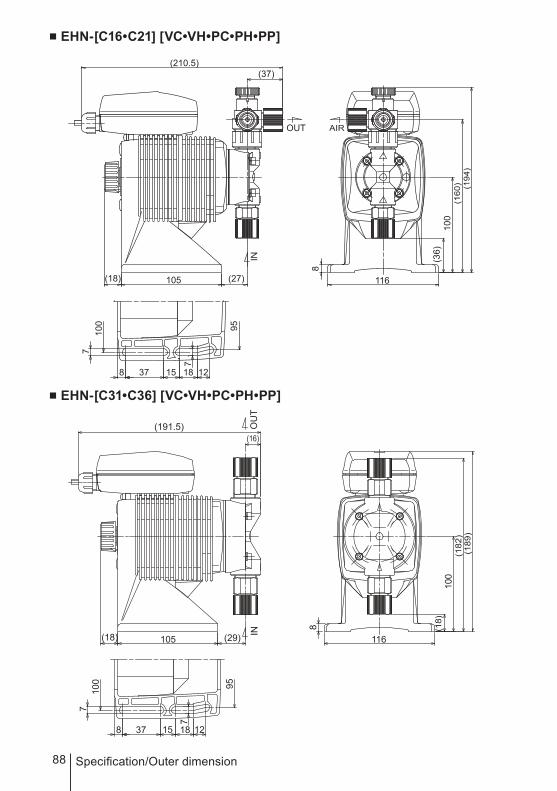
88 Specification/Outer dimension
■ EHN-[C16•C21] [VC•VH•PC•PH•PP]
■ EHN-[C31•C36] [VC•VH•PC•PH•PP]
(191.5) OU
T
(16)
(18) 105 (29) IN
100
7
8 37 15 18 12
7
95
8
116
(18)
100
(182
)(1
89)
(210.5)(37)
OUT
(18) 105 (27)
IN
95100
7
8 37 15
7
18 12
8
116
(36)
100
(160
) (194
)
AIR

89
SpecificationSpecification/Outer dimension
■ EHN-[B11•B21]FC
■ EHN-[C21]FC
INO
UT
(167)(12)
(21) (25)81.5 100
5 (27)
90(1
53)
(174
)
88
6.27 16 10 32

90 Specification/Outer dimension
■ EHN-[C31•C36]FC
INO
UT
(191.5)(16)
(18) (29)105
7
7
100
95
8 37 15 18 12
8
116
(18.5)
100
(181
.5)
(189
)

91

T668-2 '09/0
( )Country codes
IWAKI CO.,LTD. 6-6 Kanda-Sudacho 2-chome Chiyoda-ku Tokyo 101-8558 JapanTEL:(81)3 3254 2935 FAX:3 3252 8892(http://www.iwakipumps.jp)
Australia IWAKI Pumps Australia Pty. Ltd. TEL : (61)2 9899 2411 FAX : 2 9899 2421 Italy IWAKI Italia S.R.L. TEL : (39)02 990 3931 FAX : 02 990 42888Austria IWAKI (Austria) GmbH TEL : (43)2236 33469 FAX : 2236 33469 Korea IWAKI Korea Co.,Ltd. TEL : (82)2 2630 4800 FAX : 2 2630 4801Belgium IWAKI Belgium n.v. TEL : (32)1367 0200 FAX : 1367 2030 Malaysia IWAKIm Sdn. Bhd. TEL : (60)3 7803 8807 FAX : 3 7803 4800China IWAKI Pumps (Shanghai) Co., Ltd. TEL : (86)21 6272 7502 FAX : 21 6272 6929 Norway IWAKI Norge AS TEL : (47)66 81 16 60 FAX : 66 81 16 61China IWAKI Pumps (Guandong) Co., Ltd. TEL : (86)750 3866228 FAX : 750 3866278 Singapore IWAKI Singapore Pte. Ltd. TEL : (65)6316 2028 FAX : 6316 3221China GFTZ IWAKI Engineering & Trading (Guangzhou) TEL : (86)20 8435 0603 FAX : 20 8435 9181 Spain IWAKI Iberica Pumps, S.A. TEL : (34)943 630030 FAX : 943 628799China GFTZ IWAKI Engineering & Trading (Beijing) TEL : (86)10 6442 7713 FAX : 10 6442 7712 Sweden IWAKI Sverige AB TEL : (46)8 511 72900 FAX : 8 511 72922Denmark IWAKI Nordic A/S TEL : (45)48 24 2345 FAX : 48 24 2346 Switzerland IWAKI (Schweiz) AG TEL : (41)26 674 9300 FAX : 26 674 9302Finland IWAKI Suomi Oy TEL : (358)9 2745810 FAX : 9 2742715 Taiwan IWAKI Pumps Taiwan Co., Ltd. TEL : (886)2 8227 6900 FAX : 2 8227 6818France IWAKI France S.A. TEL : (33)1 69 63 33 70 FAX : 1 64 49 92 73 Taiwan IWAKI Pumps Taiwan (Hsin-chu) Co., Ltd. TEL : (886)3 573 5797 FAX : (886)3 573 5798Germany IWAKI EUROPE GmbH TEL : (49)2154 9254 0 FAX : 2154 9254 48 Thailand IWAKI (Thailand) Co.,Ltd. TEL : (66)2 322 2471 FAX : 2 322 2477Holland IWAKI Holland B.V. TEL : (31)297 241121 FAX : 297 273902 U.K. IWAKI PUMPS (UK) LTD. TEL : (44)1743 231363 FAX : 1743 366507Hong Kong IWAKI Pumps Co., Ltd. TEL : (852)2 607 1168 FAX : 2 607 1000 U.S.A. IWAKI America Incorporated TEL : (1)508 429 1440 FAX : 508 429 1386Indonesia IWAKI Singapore (Indonesia Branch) TEL : (62)21 690 6606 FAX : 21 690 6612 Vietnam IWAKI Pumps Vietnam Joint Venture Co.,Ltd. TEL : (84)613 933456 FAX : 613 933399