safety during take-off and landing for small...
TRANSCRIPT
Draft Only: September 2001
Advisory Circular
AC 91-225(0) SEPTEMBER 2001 SAFETY DURING TAKE-OFF AND LANDING
FOR SMALL AEROPLANES
CONTENTS 1. References 1
2. Purpose 1
3. Status of this AC 1
4. Definitions 2
5. General 3
6. Permission to operate and responsibilities 3
7. Assessing the suitability of an ALA 6
8. Criteria for a landing area 6
9. Pressure and density altitude 7
10. Aerodrome surface characteristics 7
11. Ambient conditions 9
12. Aeroplane characteristics and configuration 9
13. Obstacles on and in the vicinity of an aerodrome 12
14. Aeroplane information 13
15. Critical operations 13
Appendix A 15
1. REFERENCES • CASR 91.225 - Safety during take-off
and landing • CASR 91.180 Precautions before
flight
2. PURPOSE This Advisory Circular (AC) provides general information and advice to enhance the safety of taking off or landing at any place, with emphasis on unlicensed aerodromes. It is intended to give an overview of pilot responsibilities and highlight principles applicable to the operations of smaller aeroplanes, including those not fully supported by manufacturer’s take-off and landing performance data.
3. STATUS OF THIS AC This AC is the first that has been issued on this subject.
Advisory Circulars are intended to provide recommendations and guidance to illustrate a means but not necessarily the only means of complying with the Regulations, or to explain certain regulatory requirements by providing interpretative and explanatory material. Where an AC is referred to in a ‘Note’ below the regulation, the AC remains as guidance material. ACs should always be read in conjunction with the referenced regulations.

2 AC 91-225(0): Safety during take-off and landing for small aeroplanes
Draft Only: September 2001
4. DEFINITIONS In this advisory circular, unless the contrary is stated:
aerodrome means an area of land or water .(including any buildings, installations and equipment), the use of which as an aerodrome is authorised under the regulations, being such an area intended for use wholly or partly for the arrival, departure or movement of aircraft.
aircraft landing area(ALA) means a place which may be suitable for the landing and take-off of an aeroplane of appropriate certification and performance but which may not fully meet formal standards of construction, marking, maintenance or reporting.
apron means a defined area on a land aerodrome intended to accommodate aircraft for purposes of loading or unloading, fuelling, parking or maintenance.
clearway means a defined area in which there are no obstacles penetrating a slope of 2.5% rising from the end of the runway over a width of 45m.
demonstrated landing distance (DLD) means an aeroplane’s unfactored landing distance as demonstrated by the aeroplane’s manufacturer under a certification process.
factor means a safety margin applied as a multiple to an aeroplane manufacturer’s minimum take-off or landing distance data to allow for the variables experienced in normal operations (usually expressed as a percentage).
float plane means any aeroplane designed for landing or taking-off from water.
fly-over area means a portion of ground adjacent to the runway strip which is free of tree stumps, large rocks or stones, fencing or any other obstacles above ground, but which may include ditches or drains below ground level.
landing area means a place which may be suitable for the take-off and/or landing of an aircraft under appropriate conditions.
large aeroplane means an aeroplane over 5700kg MTOW.
lateral clearance area means an area each side of a runway in which obstructions are graded upward away from the runway to reduce wind-shear and provide lateral clearance in the event of divergence from the runway centre-line (see Appendix A, Figure 1).
manoeuvring area means that part of an aerodrome to be used for the take-off, landing and taxying of aircraft, excluding aprons.
maximum landing weight (MLW) means the maximum weight at which the aeroplane may land or alight.
maximum take-off weight (MTOW) means the maximum weight at which an aeroplane may commence its take-off roll.
movement means the taking off or landing of an aircraft.
movement area means that part of an aerodrome to be used for the take-off, landing and taxiing of aircraft, consisting of the manoeuvring area and the apron(s).
obstacle free area means an area where there are no wires or any other form of obstacles above the approach and take-off areas, runways, runway strips, fly-over areas or water channels.
AC 91-225(0): Safety during take-off and landing for small aeroplanes 3
Draft Only: September 2001
runway means a defined rectangular area on a land aerodrome which is prepared for the landing and take-off of aircraft.
runway strip means a portion of ground between the runway and fly-over area which is in a condition that ensures minimal damage to an aeroplane which may run off a runway during take-off or landing.
small aeroplane means an aeroplane not more than 5700kg MTOW.
alighting area means a suitable stretch of water for the landing or taking-off of a float plane or amphibian under specific conditions.
5. GENERAL
5.1 CASRs 91.180 and 91.225 require pilots to assess aircraft performance in the prevailing circumstances in order to assure the safety of their aircraft when taking off or landing. The assessment of aircraft performance must include appropriate allowances for the variables that occur in normal operations.
5.2 Aircraft performance data is supplied in the Aircraft Flight Manual (AFM), Owners Manual, Pilot’s Operating Handbook or an equivalent publication. .
5.3 There is no legal obligation on pilots of private aeroplanes below 5700kg to apply safety margins (factors) to the take-off or landing distances recommended by the aeroplane manufacturer. However, the pilot cannot reasonably expect to meet optimum performance standards during normal field operations, and if recommended safety factors are not applied, he or she must accept a greater level of personal responsibility for ensuring that safe runway distances are available in the prevailing circumstances.
*See the standard safety factors recommended for small aircraft at Table 1 to Annex A.
5.4 This AC does not aim to provide technical advice to the operators of aircraft certified under CASRs/FARs Part 25. Most aeroplanes above 5700kg MTOW and some jets below that weight are certified under FAR Part 25.
• FAR Part 25 specifies stricter and more comprehensive take-off, flight and landing performance standards than does FARs Part 23, which is the general certification standard for small aeroplanes.
• CASR 91.505 requires, all multi-engined aeroplanes with an MTOW above 8640 kg, to observe the performance requirements and factoring specified in CASRs Part 121A.
6. PERMISSION TO OPERATE AND RESPONSIBILITIES
6.1 Permission to operate. There is ownership and management of almost every potential landing place, with the possible exception of open areas of water. Unless a landing place is unambiguously open to public use for aviation the pilot should assume that approval is required before using land or water for an aircraft movement. General examples of places where approval is required would be:
• an unlicensed landing ground managed by local council or private organisation/landowner
• private farmland
• roads, parks or fairways owned by local authorities or private interests

4 AC 91-225(0): Safety during take-off and landing for small aeroplanes
Draft Only: September 2001
• water, land or dry lakes managed by a state authority such as National Parks, Waterways Authority, Lands Department, etc.
6.2 Penalties and liability. Use of a public facility such as a road or park for landing may attract a penalty from local authorities even if the physical requirements for a landing area are satisfied. Where land is not actively managed an unauthorised landing might still be considered a trespass. A liability for reckless or negligent operation may also arise if appropriate precautions were not taken to avoid conflict with other users.
6.2.1 While the law generally recognises a person’s right to take any reasonable action to save themselves in an emergency, pilots should remember that nothing in the CASRs acts to protect him/her against civil liability in the case of damage to persons or property.
6.3 Pilot responsibilities. The pilot in command has responsibility for the safety of the aircraft and those on board. He or she is required to obtain and assess all the information needed for the safety of the flight, and must not take off or land unless the information indicates that the aeroplane can operate safely.
6.4 Aerodrome information. Whether operating at an aerodrome or an ALA the pilot of an aeroplane needs to know:
• the location of the aerodrome or ALA and the features that can be used to positively identify it as the aerodrome intended for landing.
• the means of identifying the boundaries of the manoeuvring area
• whether people, machines, stock or wildlife are likely to be present at the time of movement
• the length of (suitable) runway available
• the width of the runway
• the nature of the runway and movement area surface
• the runway elevation
• the runway direction
• the runway slope
• recency and type of usage: eg., use as agricultural strip, any current fixed-wing, gliding or parachute operations etc
• surface type: eg., seal, broken seal, black soil, sandy loam, naturally soft, naturally hard, gravel, small/larger stones, etc
• surface conditions: eg., cracked, sandy, soft gravel, muddy, recently ploughed, hardened mud (rutted or stock-pitted), heavily grassed, lightly grassed, etc.
• surface moisture levels: eg., dry, moist, wet, muddy
• ambient conditions: temperature, wind, general conditions
• obstructions in the approach, take-off and lateral transition areas
• power lines near the aerodrome
• any management limits on the use of the landing place
• any special procedures applicable at the landing place: eg one off activities
AC 91-225(0): Safety during take-off and landing for small aeroplanes 5
Draft Only: September 2001
• NOTAMs or AIP Supplements applicable to the area
• for night operations: the availability, type and means of operating the aerodrome lights
• for IMC or night operations: the terrain in the vicinity of the aerodrome
6.5 No-go situations. Every pilot must learn to resist personal and external pressures to proceed without essential safety information, or when evidence suggests safety is not reasonably assured. It is also important that other persons involved in the operation are made aware that no decision to proceed will be made until all required information has been assessed. Unless and until the operation is potentially safe both common sense and regulatory requirements mean that the take-off or landing must not be attempted.
*Appendix A shows the operational elements that should be considered when assessing the safety of a proposed movement.
6.6 Landing area manager’s responsibilities. A person who gives an approval to operate must be careful to stay within his or her level of expertise. The law will usually see the provision of information as an invitation to operate, and the person giving an invitation takes on a duty of care for the welfare of the person invited. In a matter of negligence the question to be answered will usually be “was the risk reasonably foreseeable to the visitor or the class of persons to whom the visitor belongs?”
• Nothing by way of conjecture should be said, and only information known beyond reasonable doubt to be accurate should be passed. If the person who is asked for advice about a landing place is not clearly aware of the facts needed to answer a question, he or she would be well advised not to volunteer an answer. Information found to be wrong should be corrected even if the pilot is on the way.
• It is essential that a person who issues an approval to land or take off an aeroplane either:
(a) limit themselves to issuing approval to operate plus providing only known fixed information such as surveyed length of runway, aerodrome elevation and compass orientation; or
(b) given an arguable awareness of the requirements on the basis of training and experience, provide fixed information plus variable surface conditions and weather information they have reasonable grounds to believe are correct.
THE DUTY OF CARE
“Whenever a person gives information or advice to another upon a serious matter in circumstances where the speaker realises, or ought to realise, that he is being trusted to give the best of his information or advice for action on the part of the other party to act on that information or advice, the speaker comes under a duty to exercise reasonable care in the provision of the information or advice he chooses to give”
L. Shaddock & Associates Pty Ltd v Parramatta City Council (1981) 150 CLR 225
• In all cases the responsibility for safe operation rests with the pilot, and while the owner or manager has an obligation to provide factual information, he or she is not required to guarantee that an aerodrome is safe for landing or take-off.

6 AC 91-225(0): Safety during take-off and landing for small aeroplanes
Draft Only: September 2001
• A landing area’s owner or manager is less likely to be held responsible if the visitor is without a lawful right to use the aerodrome. However, the owner or manager of a clearly marked aerodrome, which is unserviceable or hazardous, would be wise to provide warning to others about its status. He or she could probably discharge any duty of care by removing the markings or by displaying an unserviceability cross on the aerodrome.
7. ASSESSING THE SUITABILITY OF AN ALA
7.1 The suitability of a landing place depends on its characteristics, the aircraft to be used and the pilot’s qualifications and skills. The landing place must meet the aircraft manufacturer’s recommended minimum standards for dimensions, slope, surface bearing capacity, obstacle-free gradients and so forth. The weather conditions must also be considered.
7.2 A pilot is authorised by virtue of his or her licence to assess these factors before deciding whether a particular movement should take place. If a pilot fails to discover or consider any significant factor affecting the safety of a movement, he or she may be liable to action in negligence.
8. CRITERIA FOR A LANDING AREA Each aircraft movement calls for a landing and take-off area of certain dimensions. The individual aircraft’s flight manual shows the dimensions required for given combinations of weight, altitude and temperature.
*Appendix A, “Dimensional and Other Guidelines for Aircraft Landing Areas (ALAs)” shows the minimum ALA physical standards for aeroplanes below 5700kg.
• Higher standards apply to licensed aerodromes, with the most stringent requirements being for licensed or private aerodromes where high capacity aeroplanes are used in commercial passenger transport operations.
9. PRESSURE AND DENSITY ALTITUDE
9.1 Pressure altitude. A significant characteristic of a landing area is its height above sea level, which, combined with the QNH, gives rise to pressure altitude. The reduction of ambient air pressure with height increases the True Air Speed (TAS) required for a given Indicated Air Speed (IAS), which affects take-off and landing distance requirements. To determine pressure altitude, apply the QNH to the aerodrome elevation. Thus a pilot on a sea level aerodrome with a QNH of 1003 would calculate 1013-1003 = 10hpa x 28ft, giving a pressure altitude of 280ft AMSL. Alternatively a pilot can read pressure altitude directly by setting standard pressure 1013.25 on the altimeter subscale.
9.2 Density altitude. Increased density altitude markedly reduces engine power output (this effect can be delayed if an aircraft is fitted with a turbocharger, which can maintain a regulated inlet air pressure to flight level heights). If necessary, density altitude can be determined by applying the ambient temperature to the pressure altitude, with each 1 deg C variation from ISA giving rise to 120ft variation in density altitude. Thus a sea level aerodrome with ISA pressure and 25 deg would have a density altitude of 1200ft. The pilot does not usually have to make a separate density altitude calculation because take-off and landing performance charts usually provide integral solutions for density altitude through entries of pressure altitude and temperature.

AC 91-225(0): Safety during take-off and landing for small aeroplanes 7
Draft Only: September 2001
10. AERODROME SURFACE CHARACTERISTICS
10.1 Rolling resistance. Rolling resistance is determined by tyre pressure, aeroplane mass, and the surface characteristics of the movement area. Up to a point, rolling resistance may be welcome during landing, but unexpected rolling resistance on take-off can lead to a decision to abort the take-off, or possibly an over-run accident.
• The limits of safety during landing would be that which caused damage to the tyres or aeroplane structure, or loss of directional control. Low tyre pressure can have a very significant effect (note how difficult it is to shift an aeroplane by pushing it about the tarmac with low tyre pressures, or experience the difference between pushing a fully-loaded wheelbarrow with a very low tyre pressure versus the same load on a tyre with higher pressure).
10.2 Surface. The main variable in rolling resistance is the nature of the runway surface. The surface may be concrete, bitumen, coral, gravel, soil, grass on soil or sand, hard packed sand or a dry salt-bed (salt lake), each with its own characteristics, many of which vary with the weather and season. Obviously the rolling resistance on concrete or bitumen is minimal and predictable, but the rolling resistance on other types of surface varies widely between surface types, and will even vary with changes in surface solidity along the length of a given runway.
• Rolling resistance can be caused by standing water on any runway surface because it builds up in front of the wheels (witness the braking effect on a car driven across a water-covered causeway).
• In the case of any natural surface the soil moisture content significantly affects rolling resistance, as does surface looseness, presence of algal growth, grass mass and characteristics, surface irregularities, and subsurface softness. Very dry is helpful on some natural surfaces but detrimental on others. With the exception of beach sand very wet almost invariably gives rise to an unsatisfactory surface. Grass density, greenness and length have a significant effect on the rolling behaviour of an aeroplane (grass can also hide obstructions, holes, water, stones, anthills and erosion trenches).
10.3 Assessing the variables. Table 1 to Annex A provides some guidance about the effects of various surface conditions, but no table can reasonably cater for all scenarios or all factors, and a pilot must develop an ability to make his/her own assessments. Some of the factors that will affect the safety of take-off are:
• transverse or lateral slope, which can affect the aerodynamics of flight, and may also result in a longer take-off roll because the pilot has to use asymmetric brake, nosewheel steering or rudder to keep straight
• gravel, which may mean a longer take-off roll because power may have to be applied slowly during the initial roll to avoid stone-chip damage to the propeller, and may, if very soft, give rise to a wave effect in front of the wheels that resists forward motion
• sand, which is usually worse than gravel in terms of creating rolling resistance
• grass, which resists the passage of an aeroplane rolling over it: while attempts are made to predict the effects of certain lengths of grass, rolling resistance will vary
8 AC 91-225(0): Safety during take-off and landing for small aeroplanes
Draft Only: September 2001
not just with the length, but also freshness, moisture content, density of stalks and the mass of material present
• free water, which not only affects the softness or slipperiness of the surface but can build up in front of an aeroplane’s wheels and cause a resistance to rolling, or at higher speeds, lift the wheels and cause aquaplaning and difficulty in maintaining directional control
• water in soil, can create mud, which can affect an aircraft’s direction control and may choke spats or wheel-wells and restrict rotation of it’s wheels. In addition, soft spots may allow an aeroplane’s wheel(s) to sink enough for the propeller to hit the ground, or may cause erratic rates of acceleration during a take-off.
• bearing capacity, which is related to the type of runway surface and the aeroplane’s weight and tyre pressure. If the bearing capacity is insufficient for the combination of aeroplane, tyres and surface, a form of bogging may occur even in dry conditions (as might be experienced when driving a vehicle over sand or a freshly ploughed paddock).
10.4 Reliability of information. Be aware that some ALAs may be managed by persons who have limited ability to assess the proposed landing area’s operational status. A pilot could get approval to land and related information from the manager of a proposed landing area but may not have full confidence in the quality of the information received. In such a case the pilot has to accept that there is no basis for an operational decision to proceed, and should cancel the flight or operate to the nearest aerodrome (see the definition).
11. AMBIENT CONDITIONS
11.1 Wind-speed and direction. Every pilot knows that wind can dramatically affect the length of runway required for take-off or landing. Likewise, every aeroplane should be provided with charts that can be used to calculate the effects of various wind scenarios on performance and runway requirements.
11.2 Humidity. Light aeroplane data does not usually include a humidity correction, but all engines are adversely affected to some degree by high humidity because water vapour displaces oxygen and reduces temperature rise during combustion. If the aeroplane’s documentation provides relevant information the pilot should allow for the effects of humidity in a critical take-off.
12. AEROPLANE CHARACTERISTICS AND CONFIGURATION
12.1 Performance data. The performance of every certificated aircraft has been evaluated as a part of the certification process. The certification process allows the manufacturer to determine the take-off and landing performance under ideal conditions (see para 14.2).
12.2 Factoring. “Factors” are safety margins applied to the calculation of take-off and landing distance requirements to allow for random variables in aircraft, pilot and runway surface performance encountered in normal operations. Safety factors need to be applied because an aeroplane manufacturer’s advertised performance figures are determined by a company test pilot on a good surface using a finely tuned machine in ideal weather conditions.

AC 91-225(0): Safety during take-off and landing for small aeroplanes 9
Draft Only: September 2001
• Transport operations. Regardless of whether the aeroplane has been certified under Part 23 or 25, aeroplanes operated under CASRs Part 121A and 121B usually require factoring of performance data to provide appropriate safety margins. Even if the requirements are already reflected in their take-off and landing performance charts, pilots must be familiar with any factoring applicable to their operation.
• Private operations. As mentioned earlier, the regulations don’t require the application of any factoring for small aeroplanes in private operations except in certain circumstances such as land and hold short operations (LAHSO), where a common standard has to apply to all participants. However, CASR 91.505 requires most large aeroplanes in any category of operation to comply with CASR Part 121A factoring requirements when calculating landing and take-off requirements.
(Examples. Two examples of the factoring requirements applicable to large or commercial aeroplanes are:
◊ Most turbine-engined aeroplanes are required to take off on a runway that is the greater of 1.15 times the all-engines-operating take-off distance, or the one-engine-inoperative accelerate-stop distance required (the distance used to establish V1).
◊ Jet transports must land only on a runway which is at least 1.67 times the Designated Landing Distance (DLD) (the FAA say that the DLD is not to exceed 60% of the runway available, which amounts to the same thing), with further allowances for wet runways)
• Range of requirements. A range of requirements may apply according to whether the aeroplane is jet or propeller-driven, the type of operation and the MTOW, so operators and pilots of large aeroplanes must familiarise themselves with the relevant rules.
*See Appendix A Table 1.
12.4 Weight Altitude Temperature (WAT) limitations. It is important to remember that there is more to performance than the ability to take-off and land within the available length of runway, and that expected standards of normal (and in the case of multi-engined aircraft, emergency) climb performance is predicated on meeting the weight limitations specified under the aircraft’s certification status. To ensure that climb performance does not fall below prescribed minimums, most aircraft flight manuals (AFMs) give take-off and landing weights that should not be exceeded at the prevailing altitude and temperature.
12.5 Performance category. Aeroplane performance categories are a ICAO classification system used in the development of instrument approach procedures. Turning radii for each aeroplane category are based on a manoeuvring speed of 1.3 times the stalling speed in the approach configuration at MLW. The radii are used to draw up instrument approach charts for the various categories of aeroplanes. An aeroplane’s performance category is based on its approach speed, but does not take account of the braking or other stopping qualities of the machine, and should not be used to assess the runway requirements of individual aeroplanes.
12.6 Flap settings. The use of flap during take-off may be optional, or it may be the standard configuration for the aircraft. The latter is most likely to be the case in aeroplanes
10 AC 91-225(0): Safety during take-off and landing for small aeroplanes
Draft Only: September 2001
with wings optimised for higher indicated airspeeds. Pilots should be aware that while flap generally reduces the take-off roll by permitting lift-off at a slower speed, drag is always increased and the rate of climb after take-off is reduced until flap is retracted. Despite the reduced rate of climb, use of flap will allow a slightly slower take-off safety speed, which usually results in a steeper climb angle than in the clean configuration.
• Where a take-off flap setting is optional, flap can be used to reduce rolling resistance on a soft or rough runway (and thus the length of the ground roll), but it would normally be retracted at a safe speed after take-off and the aeroplane then allowed to accelerate to the speed for best rate of climb.
12.7 Braking performance. The nominal braking performance of an aeroplane is a design feature of each aeroplane type. Braking performance is also a function of runway surface conditions, availability of anti-skid, the pilot’s braking technique, tyre condition and inflation, brake disc condition and residual temperature, aeroplane speed and mass, and the presence of slush, mud, water and other more subtle factors. In the case of a minimum field landing in an aeroplane, which is not equipped with anti-skid, one of the major difficulties is the pilot’s ability to judge the application of maximum brake just short of wheel-skid. All of the relevant factors must be considered when assessing the aeroplane’s likely performance in a critical situation.
12.8 Reverse thrust. Most jets have thrust reversers and all modern turbo-prop aeroplanes have reversible propellers. Reverse thrust can significantly reduce ground roll, but the power available from full reverse thrust is considerably less than forward thrust. Reverse thrust effectiveness varies, but for jet engines it is typically 20 to 50% of forward thrust, with somewhat better returns from turboprop configurations. Aeroplane manufacturers sometimes provide performance manuals which include accelerate-stop and landing distance charts showing the effect of reverse thrust on stopping distance, but official AFMs do not contain charts which include the effect of reverse thrust.
• While the availability of reverse thrust does not reduce the length of runway dictated by the AFM for landing, its use reduces brake and tyre wear and can be an important factor in turnaround times which might otherwise be limited by residual brake and tyre heating. Reduced landing roll through the use of reverse thrust can also minimise runway occupation times at busy aerodromes, and may be helpful in reducing taxi distances, depending on the aerodrome configuration.
• The pilot who uses reverse thrust has to be alert to the possibility of slow or asymmetric application of reverse thrust, or engine or propeller malfunction, and must therefore avoid planning to land at any place where its availability is critical to safety. Notwithstanding, reverse thrust may be useful in an emergency situation where a pilot has to land on a short or slick runway, and can still be of use during an asymmetric landing on a minimum field (but not a slick runway) provided the pilot has practised its use in the asymmetric configuration.
12.9 Propeller strikes and engine damage. A muddy, irregular or watery surface on an aerodrome or taxiing area can cause a propeller tip strike that may not be noticed by the pilot. When operating on a natural surface runway, careful preflight inspections of the propeller(s) are imperative.
• If a tip-strike happens during taxi for take-off it could easily result in an abandoned take-off, and possibly a major accident. Any propeller strike will probably cause some form of blade bending, distortion or delamination, but a

AC 91-225(0): Safety during take-off and landing for small aeroplanes 11
Draft Only: September 2001
serious strike will bend the tips back, distort the angle of the blades, may damage a gear-case or bend the propeller shaft, and will usually give rise to severe and probably dangerous vibration.
• If damage has occurred it cannot be ignored and will not correct itself. If a pilot has any reason to at all to suspect that a propeller may have struck the ground during taxi for take-off the only rational thing to do is to shut down the engine and inspect the propeller before attempting take-off.
12.10 FOD, gravel and dust. Foreign object damage (FOD) to a turbine engine may cause loss of power or complete failure. FOD frequently arises when gravel is sprayed into the engine intake by the nosewheel, or picked up in a vortex under the engine intake at high power.
• Vortices are especially pernicious if thrust is reversed during a landing, and it is recommended that reverse thrust be reduced and cancelled as speed decreases to taxi speed on an unswept bitumen or natural surface runway.
• Dust will damage both piston and turbine engines, but can be reduced in piston engines by use of filtered air. Pilots should be aware that full power for take-off is predicated on selection of unfiltered ram air, and that carburettor heat is usually unfiltered.
• Foreign objects, especially gravel, may cause propeller chipping and may give rise to propeller cracks after being caught up in the propeller tip vortices of an engine doing a run-up, or at high rpm during the early stages of take-off. The possibility of propeller damage by gravel may be a significant operational consideration in a take-off from an unswept bitumen or a natural surface, because while the potential for damage can be greatly reduced by progressive application of power during the take-off roll (thus reducing vortices), the take-off distance required is usually calculated assuming full power at brakes release.
13. OBSTACLES ON AND IN THE VICINITY OF AN AERODROME
13.1 Runway ends. The ideal runway will have an extended surface that can be used for bringing an aeroplane to a safe halt after an over-run of the runway. An obstacle-free surface extension that is not sound enough to permit normal operation of an aeroplane may nevertheless minimise structural damage if an aeroplane undershoots or overruns the runway.
13.2 Obstruction-free areas. Obstruction free areas on a runway extended centre-line provide for low angles of take-off and safe clearance on approach. A significant clear area at the end of a runway may have an important psychological effect on the way a pilot handles an aeroplane during take-off and landing.
• During take-off, close-in obstructions on the runway extended centre-line may cause a pilot to lift off early and climb at an excessive angle, which will aggravate any problem of poor view of obstructions through the windscreen at high pitch angles, which in turn may lead to a further increase in pitch.
• During landing, high ground or obstructions in the approach area can cause a pilot to adopt a high approach path. Significant obstacles below the runway such as sea walls, creeks or ditches may also cause a pilot to approach at an excessively

12 AC 91-225(0): Safety during take-off and landing for small aeroplanes
Draft Only: September 2001
high angle and then land long. This effect is likely to be worse when the aeroplane has poor forward visibility or is approaching in a flapless configuration.
13.3 Emergency alighting areas, and climb in the event of engine failure during take-off. Among the characteristics of a good aerodrome for single-engined aeroplanes is an area accessible from the lift-off point to safe manoeuvring height that is suitable for carrying out a forced landing in the event of engine failure after take-off. Similarly, for twin-engined aeroplanes, a good aerodrome will have an obstacle-free, low-angle departure area where an engine failure could be handled with minimum danger of striking ground or obstacles.
13.4 Light conditions. Pilots should not underestimate the potential difficulty of taking-off or landing directly into a low sun, and should take into account haze, smoke or low light when manoeuvring in the vicinity of an aerodrome or looking for other traffic. In particular, if a take-off or landing into the sun is known to be likely, the pilot should make every effort to ensure the windscreen is clean.
14. AEROPLANE INFORMATION.
14.1 Aeroplane certification standard. The certification standard specifies what information must be provided in the AFM. Multi-engined aeroplanes must have single-engine climb information (at least in the cruise configuration) in the flight manual CASRs/FARs Part 23 requires Part 23 aeroplanes certificated for ten or more seats to have accelerate-stop distance information. Most Part 23 aeroplanes are not designed for fail-safe operation in the same way that large aeroplanes are meant to perform. Each aeroplane type and category has a certification standard, the operational details of which are reflected in the flight manual
14.2 Demonstrated landing distance. Part 23 requires the manufacturer of an aeroplane to demonstrate the landing distance required for the aeroplane. The demonstrated landing distance (DLD) is the figure supplied by the manufacturer for the pilot to use as the basis for assessment of landing distance required for a particular landing. Pilots should be aware that the aeroplane manufacturer has a vested interest in publishing the minimum distance obtained in a landing under the conditions permitted for the tests. The requirements for the test are:
• the aeroplane must approach at not less than 1.3 times the stall speed in the landing configuration;
• the aeroplane must cross the threshold at not less than 50ft;
• the test must be done on a dry, sealed surface; and
• the aerodrome must be within 2% slope up and 2% down.
• the manufacturer is also at liberty to have the certification done by an experienced test pilot authorised to fly as aggressively as possible short of damaging the aeroplane. It follows that pilots conducting normal operations are highly unlikely to replicate the aeroplane manufacturer’s DLD in normal operations, and therefore have a duty of care to apply appropriate safety margins.
14.3 Performance information. The aircraft’s flight manual, owner’s manual, operating handbook or placarding should provide relevant performance information, but presentations are not standardised. Learning how to find and interpret a particular

AC 91-225(0): Safety during take-off and landing for small aeroplanes 13
Draft Only: September 2001
aircraft’s performance information should be part of a pilot’s familiarisation with the aeroplane.
14.4 Relevant nomenclature. There are few standard “V speeds” or suchlike performance notations formally applicable to small aeroplanes. Notwithstanding, a number of notations are frequently used to describe small aeroplane performance parameters.
*A list of notations in common usage for large and small aircraft are shown at Annex A Table 4.
15. CRITICAL OPERATIONS
15.1 Land and hold short operations (LAHSO). LAHSO is a landing procedure in use at some tower-controlled aerodromes, which involves the simultaneous operation of two aeroplanes on crossing runways, one being “active” (stopping short of an active runway) while the other is “passive” (using the full length of a crossing runway). The pilot of the “active” aeroplane is responsible for determining that his or her aeroplane can be landed and stopped short of the stopping point (usually 75M before a runway intersection). Therefore, before accepting the LAHSO, the pilot of the “active” aeroplane must establish the length of runway available to the stopping point and calculate the factored distance required for the particular landing.
• Regardless of the certification standard of the “active” aeroplane, its DLD in the prevailing circumstances must be multiplied by the factors applicable to high capacity operations to ensure that the same level of safety is applied to all participants.
• LAHSO is only available at certain aerodromes, and at those, only when ATC is operating. It is described in the AIP, and pilots must have relevant training before they can accept a hold-short landing.
15.2 One-way operations. One-way operations are little used in Australia except in some hill-country agricultural operations, usually fertiliser dropping. If the only available landing strip faces into a hill, landings have to take place toward the hill and take-offs made away from the high ground. A problem with many one-way landing strips is that rising ground precludes a go-around beyond some point short of the target threshold.
• Don’t try to use a one-way strip unless you are highly experienced or formally trained, and have recent practice in landing in minimum distance. If a pilot intends to operate off one-way strips, logbook evidence of skill training by an experienced agricultural instructor would be a wise precaution against insurance problems and general liability.
• Many one-way strips have a steep slope, and even experienced pilots may have difficulty with perspective on final - a normal approach angle is likely to appear too steep, causing the pilot to descend to establish an abnormally shallow approach angle with a high approach speed. If the landing area backs on to high ground the pilot may find him or herself committed to a landing above target threshold speeds and either try for a go-around and fail to outclimb the gradient, or have to proceed with a high-speed landing that results in over-running the (usually short) landing strip.
• Another major problem for one-way operations is the possibility of adverse winds. Tail winds on a minimum length strip are a recipe for disaster, and turbulent
14 AC 91-225(0): Safety during take-off and landing for small aeroplanes
Draft Only: September 2001
winds in hilly areas can cause severe handling problems even if they are generally in the optimum direction.

AC 91-225(0): Safety during take-off and landing for small aeroplanes 15
Draft Only: September 2001
APPENDIX A
DIMENSIONAL AND OTHER GUIDELINES FOR AEROPLANE LANDING AREAs (ALAs)
1 USE OF LANDING AREAS BY LARGE AEROPLANES
1.1 For non commercial operations the pilot in command of an aeroplane must ensure that the aeroplane only takes off or lands at aerodromes which have physical characteristics, visual aids, facilities and obstacle limitation surfaces that are adequate for the safe operation of the aeroplane, taking into account whether the operation is to be conducted by day or by night, the weather minima to be used and requirements relating to the aeroplane’s performance.
2. RECOMMENDED MINIMUM PHYSICAL CHARACTERISTICS OF LANDING AREAS AND WATER ALIGHTING AREAS
2.1 Runway Width. For other than agricultural operations, a minimum width of 15 metres is recommended, although experienced pilots can operate aeroplanes with a MTOW less than 2000kg on runways as narrow as 10 metres provided there is little or no cross-wind. If the pilot cannot comfortably straddle the mainwheels across the centreline of a sealed runway for the entire ground-roll, a take-off or landing on a strip less than 20 metre wide should not be attempted. Inexperienced pilots should be very cautious about using a narrow strip, especially if the edges of the strip are rough, soft, or otherwise likely to slew or damage the aeroplane. In addition, each aeroplane type has different handling characteristics that need to be taken into consideration.
• For agricultural operations, operating on runways less than 10 metres is not recommended.
2.2 Runway length for landing. A runway length at least equal to that specified in the aeroplane's flight manual (or approved alternative) for the prevailing conditions is generally the minimum acceptable. If an unfactored landing distance (the DLD) is shown in the AFM, the pilot should call for at least 15% additional landing distance.
• Qualified agricultural pilots may conduct day operations off runways equal to 75% of the runway requirements specified in the aeroplane's flight manual for the prevailing conditions, provided that (at least) the remaining 25% of the nominal runway length is available as clearway, and given that the aeroplane approaches to land over the clearway and takes off toward the clearway.
• Night agricultural operations should be conducted off runways at least 50% longer than those required for day operations, preferably with additional clearway because obstructions will be unlit.
2.3 Longitudinal Slope. The longitudinal slope between the runway ends should not exceed 2%, except that 2.86% is considered safe on part of the runway so long as the change of slope is gradual. In agricultural operations, runway slope should not exceed 12.5% for day and 2% for night operations.
• Where overall slope exceeds 2% the runway should be used only for one-way operations, with landing uphill and take-off downhill.

16 AC 91-225(0): Safety during take-off and landing for small aeroplanes
Draft Only: September 2001
2.4 Transverse Slope. The transverse slope between the extreme edges of the runway strip should not exceed 2.5% or 12.5% upward slope over the fly-over area. For agricultural day operations, the transverse slope should not be more than 3% over the runway and 5% over the runway strip.
2.5 Wind. The effects of wind cannot be ignored because it dramatically affects the distance required for a landing or take-off. A windsock is the preferred method of determining wind, and is a must if the aerodrome is used frequently. In other cases, consider having a person provide a smoke signal (fire or smoke flare) clear of the approach path near the approach end of the runway.
2.6 Other Physical Characteristics. Both ends of a runway should have approach and take-off areas clear of objects above a 5% slope for day and a 3.3% slope for night operations. If an object or terrain projects above the surveyed angle it must be sufficiently far away to allow an aeroplane taking off to turn before it is reached, and to permit a safe turn onto finals. Other recommended landing area physical characteristics are shown on the following diagrams:

AC 91-225(0): Safety during take-off and landing for small aeroplanes 17
Draft Only: September 2001
Figure 2A - Lateral clearance area Single engine and centre-line thrust aeroplanes not exceeding 2000kg
MTOW (day operations)
Figure 2B - Other Aeroplanes (day operations)
Figure 3 - Dimensions (night operations)
Figure 4 - Dimensions - agricultural day operations
Figure 5 - Dimensions - agriculture night operations
18 AC 91-225(0): Safety during take-off and landing for small aeroplanes
Draft Only: September 2001
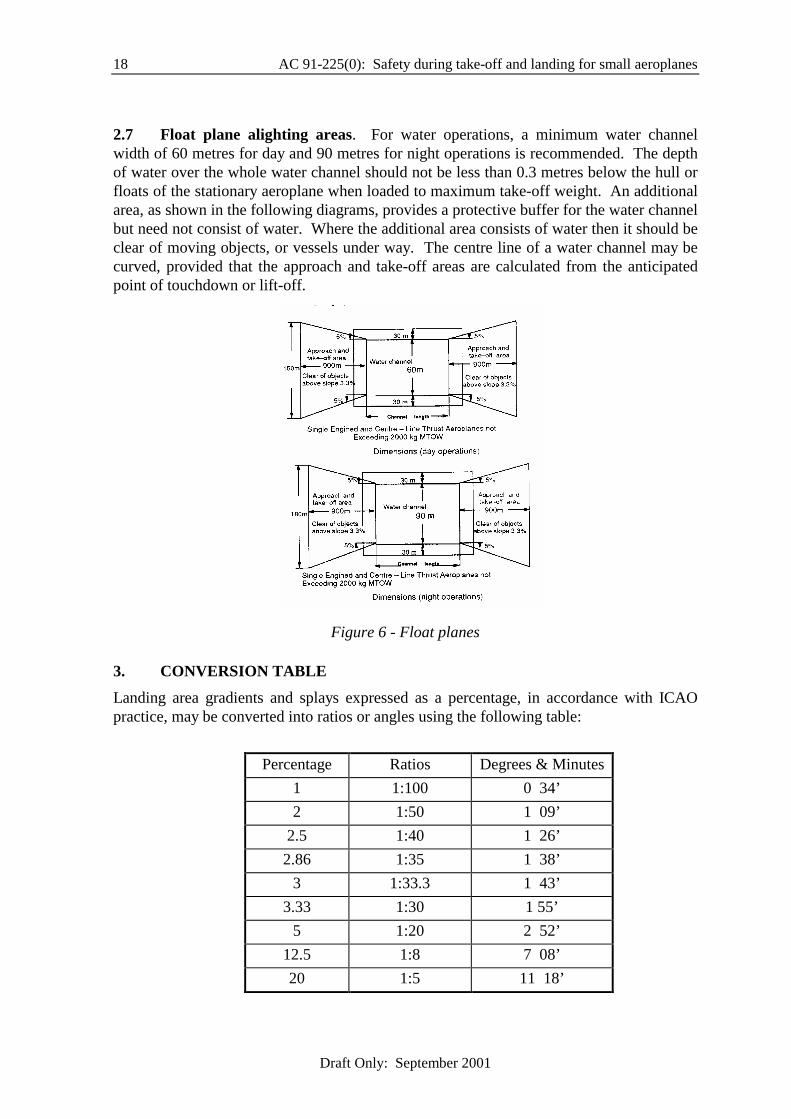
2.7 Float plane alighting areas. For water operations, a minimum water channel width of 60 metres for day and 90 metres for night operations is recommended. The depth of water over the whole water channel should not be less than 0.3 metres below the hull or floats of the stationary aeroplane when loaded to maximum take-off weight. An additional area, as shown in the following diagrams, provides a protective buffer for the water channel but need not consist of water. Where the additional area consists of water then it should be clear of moving objects, or vessels under way. The centre line of a water channel may be curved, provided that the approach and take-off areas are calculated from the anticipated point of touchdown or lift-off.
Figure 6 - Float planes
3. CONVERSION TABLE Landing area gradients and splays expressed as a percentage, in accordance with ICAO practice, may be converted into ratios or angles using the following table:
Percentage Ratios Degrees & Minutes
1 1:100 0 34’ 2 1:50 1 09’
2.5 1:40 1 26’ 2.86 1:35 1 38’
3 1:33.3 1 43’ 3.33 1:30 1 55’
5 1:20 2 52’ 12.5 1:8 7 08’ 20 1:5 11 18’
AC 91-225(0): Safety during take-off and landing for small aeroplanes 19
Draft Only: September 2001
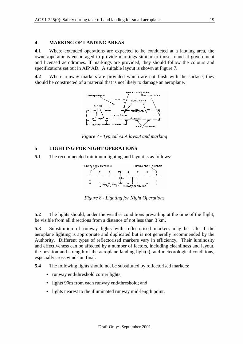
4 MARKING OF LANDING AREAS
4.1 Where extended operations are expected to be conducted at a landing area, the owner/operator is encouraged to provide markings similar to those found at government and licensed aerodromes. If markings are provided, they should follow the colours and specifications set out in AIP AD. A suitable layout is shown at Figure 7.
4.2 Where runway markers are provided which are not flush with the surface, they should be constructed of a material that is not likely to damage an aeroplane.
Figure 7 - Typical ALA layout and marking
5 LIGHTING FOR NIGHT OPERATIONS
5.1 The recommended minimum lighting and layout is as follows:
Figure 8 - Lighting for Night Operations
5.2 The lights should, under the weather conditions prevailing at the time of the flight, be visible from all directions from a distance of not less than 3 km.
5.3 Substitution of runway lights with reflectorised markers may be safe if the aeroplane lighting is appropriate and duplicated but is not generally recommended by the Authority. Different types of reflectorised markers vary in efficiency. Their luminosity and effectiveness can be affected by a number of factors, including cleanliness and layout, the position and strength of the aeroplane landing light(s), and meteorological conditions, especially cross winds on final.
5.4 The following lights should not be substituted by reflectorised markers:
• runway end/threshold corner lights;
• lights 90m from each runway end/threshold; and
• lights nearest to the illuminated runway mid-length point.

20 AC 91-225(0): Safety during take-off and landing for small aeroplanes
Draft Only: September 2001
6 OTHER FACTORS THAT SHOULD BE CONSIDERED PRIOR TO USING A LANDING AREA
6.1 A pilot should not use a landing area unless the aeroplane can be kept clear of all persons, animals, vehicles or other obstructions.
6.2 Geographic Location. A landing area should not be located:
• under an instrument approach area or in such a position that it presents a hazard to aircraft conducting a published instrument approach;
• within any area where the density of aircraft movements creates a hazard; or
• where take-off or landing over buildings, noise sensitive livestock or populated areas causes a nuisance or hazard.
6.3 If a proposed landing area is located near a city, town or populous area or any other area where noise or other environmental considerations make aeroplane operations undesirable, the availability of such a landing area may be affected by the provisions of relevant environmental legislation.
7. MEASURING AN AERODROME
7.1 Distances. The length of a potential runway can be established in a number of ways. Always measure twice, preferably by different methods and round measurements down to ensure that the results are conservative. Common methods of measuring are:
• pacing: all individuals have their own stride length which can be established by averaging, with about .75metre being a common walking stride that might be used to determine the length of a runway, and 1 metre being a long, deliberate stride that might be used to find the width of a runway;
• motor: the odometer of a calmly driven vehicle or motorcycle can be used to measure the length of a runway and many clearways;
• measuring wheel: the best method, with wheels commonly available and used for a variety of land measuring tasks.
7.2 Slope. If the slope is seen as significant it can be measured by farm or surveyor’s inclinometer, or the pilot may take altimeter readings at both ends of the runway, convert the altimeter reading to metres and divide the altitude difference by strip length to get slope. For example, if the altimeter reading at each end of a 800m runway differs by 55 ft (16m) the ratio is established at 1:50 by dividing runway length with the height difference (800/16). This equates to a slope of 2% (refer to the conversion table para.3.
8. SURFACE TESTING OF A LANDING AREA
8.1 Rough surfaces. The presence of holes, cracks and ruts will degrade aeroplane performance and handling and increase the possibility of structural damage. Driving a stiffly sprung vehicle along the runway at a speed of at least 75 kph can test the smoothness of a runway. If this does not cause significant discomfort to the occupants of the vehicle, the surface can be considered satisfactory.

AC 91-225(0): Safety during take-off and landing for small aeroplanes 21
Draft Only: September 2001
8.2 Soft, wet surfaces. A test vehicle should be driven in a zig-zag pattern at a speed not exceeding 15 kph along the full length and width of the runway. Particular attention should be paid to suspect areas with up to three passes over suspect ground. If the vehicle’s tyre marks exceed a depth of 25mm the surface is not suitable for any aeroplane which can be reasonably represented by the test vehicle. As a rule, an aeroplane with small wheels or high tyre pressures will require harder runways. If recent heavy rain or other waterlogging has occurred, the ground should be tested with a crowbar in several places along the runway to ensure that a dry surface crust does not conceal a wet base.
9. FACTORS AND NOTATIONS
9.1 After establishing the aeroplane’s runway requirements in the prevailing density altitude and wind conditions by consulting the AFM it is recommended that the unfactored (DLD) runway length required by the AFM be multiplied by a safety factor related to MTOW of the aeroplane. The standard factors shown in Table 1 are recommended for private operations in small aeroplanes:
Table 1: STANDARD FACTORS
For TAKE-OFF
• for all MTOWs 1.15 or 115%
For LANDING
• up to 2000kg MTOW 1.15 or 115%
• 2000 to 4500kg (See 9.2) 1.15 to 1.43
• 4500 to 5700kg 1.43 or 143%
*Note: CASR 91.505 requires the operators of most aeroplanes above 8640kg to operate to the standards expressed in CASRs Part 121A.
9.2 in the case of aeroplanes having an MTOW between 2000kg and 3500kg, a factor determined by linear interpolation between 1.15 and 1.43;
9.3 After factoring the DLD in accordance with Table 1 the pilot should apply further factors in accordance with any guidance given in the AFM. If the AFM is not helpful, consider applying any of the allowances shown in Tables 2 and 3 below that are relevant to the flight.

22 AC 91-225(0): Safety during take-off and landing for small aeroplanes
Draft Only: September 2001
Table 2: CONTINGENCY TAKE-OFF ALLOWANCES
Circumstance Approximate Increase In Factor Multiple Take-off Distance to 50 Ft • per 10% increase in aeroplane weight 20% 1.2 • an increase of 1000 ft in airfield altitude 10% 1.1 • an increase of 10C in ambient temperature 10% 1.1 • dry grass* up to 20 cm (on firm soil) 20% 1.2 • wet grass** up to 20 cm (on firm soil) 30% 1.3 • 2% uphill slope* 10% 1.1 • a tailwind component = 10% of lift-off speed 20% 1.2 • soft ground or snow* 25%+ 1.25 + (These effects are additive)
* Effects are variable and possibly unpredictable. Expect a ground distance increase, but airborne distance remains the same
** If wet grass is on soft ground the effect on rolling resistance is cumulative, so both elements must be considered.
Table 3: CONTINGENCY LANDING ALLOWANCES
Circumstance Approximate Increase In Factor Multiple Landing Distance From 50 Ft • a 10% increase in aeroplane weight 10% 1.1 • an increase of 1000 ft in airfield altitude 5% 1.05 • an increase of 10C in ambient temperature 5% 1.05 • dry grass* - up to 20 cm (on firm soil) 20%+ 1.2 • wet grass* - up to 20 cm (on firm soil) 30%+ 1.3 • short and dense or very green grass* 60% 1.6 • 2% downhill slope 10% 1.1 • tailwind component, per 10% of landing speed# 20% 1.2 • light snow or surface muddiness 25%+ 1.25+ • 20-50mm standing water* 50%+ 1.5+ (These effects are additive)
* Effects are variable and possibly unpredictable. While rolling resistance is increased, reduced braking effectiveness has the greater effect. Airborne distance remains the same but expect an increase in ground distance.
# In factoring the effect of wind, reduce estimated headwind by 50% and assume that a tailwind is 50% greater than the estimate.
AC 91-225(0): Safety during take-off and landing for small aeroplanes 23
Draft Only: September 2001
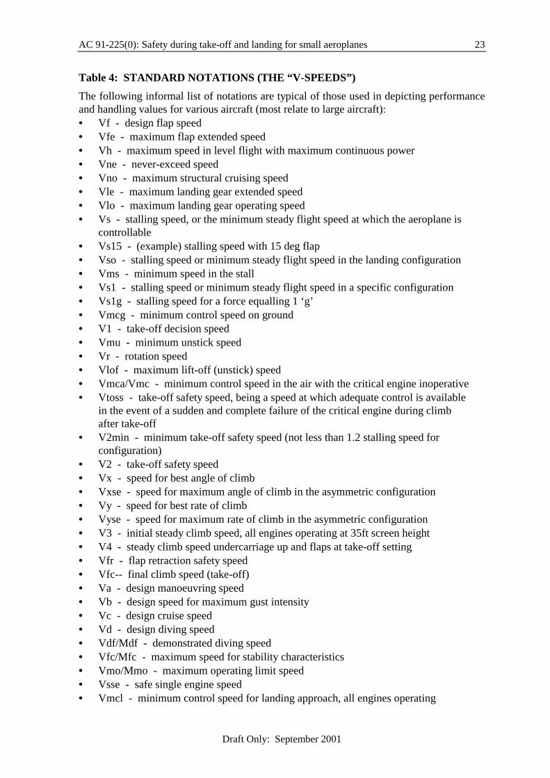
Table 4: STANDARD NOTATIONS (THE “V-SPEEDS”) The following informal list of notations are typical of those used in depicting performance and handling values for various aircraft (most relate to large aircraft): • Vf - design flap speed • Vfe - maximum flap extended speed • Vh - maximum speed in level flight with maximum continuous power • Vne - never-exceed speed • Vno - maximum structural cruising speed • Vle - maximum landing gear extended speed • Vlo - maximum landing gear operating speed • Vs - stalling speed, or the minimum steady flight speed at which the aeroplane is
controllable • Vs15 - (example) stalling speed with 15 deg flap • Vso - stalling speed or minimum steady flight speed in the landing configuration • Vms - minimum speed in the stall • Vs1 - stalling speed or minimum steady flight speed in a specific configuration • Vs1g - stalling speed for a force equalling 1 ‘g’ • Vmcg - minimum control speed on ground • V1 - take-off decision speed • Vmu - minimum unstick speed • Vr - rotation speed • Vlof - maximum lift-off (unstick) speed • Vmca/Vmc - minimum control speed in the air with the critical engine inoperative • Vtoss - take-off safety speed, being a speed at which adequate control is available
in the event of a sudden and complete failure of the critical engine during climb after take-off
• V2min - minimum take-off safety speed (not less than 1.2 stalling speed for configuration)
• V2 - take-off safety speed • Vx - speed for best angle of climb • Vxse - speed for maximum angle of climb in the asymmetric configuration • Vy - speed for best rate of climb • Vyse - speed for maximum rate of climb in the asymmetric configuration • V3 - initial steady climb speed, all engines operating at 35ft screen height • V4 - steady climb speed undercarriage up and flaps at take-off setting • Vfr - flap retraction safety speed • Vfc-- final climb speed (take-off) • Va - design manoeuvring speed • Vb - design speed for maximum gust intensity • Vc - design cruise speed • Vd - design diving speed • Vdf/Mdf - demonstrated diving speed • Vfc/Mfc - maximum speed for stability characteristics • Vmo/Mmo - maximum operating limit speed • Vsse - safe single engine speed • Vmcl - minimum control speed for landing approach, all engines operating

24 AC 91-225(0): Safety during take-off and landing for small aeroplanes
Draft Only: September 2001
• Vat - target threshold speed • Vmt - minimum threshold speed • Vtmax - maximum speed at the landing threshold • Vat1 - target threshold speed, one engine out • Vtd - touch-down speed • Vp - aquaplaning speed • Vmbe - maximum speed for brake energy absorption capability