safety analysis report for the radioactive scrap and … library...for the radioactive scrap and...
TRANSCRIPT

The INL is a U.S. Department of Energy National Laboratory operated by Battelle Energy Alliance.
Document ID: SAR-407 Revision ID: 3
Effective Date: 08/23/12
Safety Analysis Report
Materials and Fuels Complex
Safety Analysis Report for the Radioactive Scrap and Waste Facility (MFC-771)
Further dissemination authorized to DOE and DOE contractors only; other requests shall be approved by the originating facility or higher
DOE programmatic authority.

INTENTIONALLY BLANK

Form 412.09 (Rev. 10)
Idaho National Laboratory
SAFETY ANALYSIS REPORT FOR THE RADIOACTIVE SCRAP AND WASTE
FACILITY (MFC-771)
Identifier: Revision: Effective Date:
SAR-407 3 08/23/12 Page: iii of x
Materials and Fuels Complex Safety Analysis Report USE TYPE N/A eCR Number: 596528 Manual: MFC RSWF Nuclear Safety Basis Manual (IAG, LST, DSA)
REVISION LOG
Rev. Date Affected Pages Revision Description
0 06/11/09 All New Issue. See eCR 562181.
1 04/13/10 Exec Sum, Chapters 1-6 and
9-11
2009 annual update. Made editorial corrections, updated figures, and updated references. All chapters, including those not revised, were rolled to Revision 1. See eCR 572537.
2 03/03/11 Chapters 2, 3, and 4
2010 annual update. Made editorial corrections and updates. All chapters, including those not revised, were rolled to Revision 2. See eCR 584004.
3 08/23/12 Exec Sum and Chapters 1-6
Revised to support the use of FTCs and ISCs and open-air transfers. Other editorial changes as needed. All chapters, including those not revised, were rolled to Revision 3. See eCR 596528.
NOTE: Each chapter of this document has an individual revision number. The revision number identified in the first column is the revision number for the Front Matter (SAR-XXX) section of this document.

Form 412.09 (Rev. 10)
Idaho National Laboratory
SAFETY ANALYSIS REPORT FOR THE RADIOACTIVE SCRAP AND WASTE
FACILITY (MFC-771)
Identifier: Revision: Effective Date:
SAR-407 3 08/23/12 Page: iv of x
INTENTIONALLY BLANK

Form 412.09 (Rev. 10)
Idaho National Laboratory
SAFETY ANALYSIS REPORT FOR THE RADIOACTIVE SCRAP AND WASTE
FACILITY (MFC-771)
Identifier: Revision: Effective Date:
SAR-407 3 08/23/12 Page: v of x
CONTENTS
Section Title Rev. Date
Front Matter and Table of Contents 3 08/23/12
Executive Summary 3 08/23/12
Chapter 1 Site Characteristics 3 08/23/12
Chapter 2 Facility Description 3 08/23/12
Chapter 3 Hazard and Accident Analyses 3 08/23/12
Chapter 4 Safety Structures, Systems, and Components 3 08/23/12
Chapter 5 Derivation of Technical Safety Requirements 3 08/23/12
Chapter 6 Prevention of Inadvertent Criticality 3 08/23/12
Chapter 7 Radiation Protection 3 08/23/12
Chapter 8 Hazardous Material Protection 3 08/23/12
Chapter 9 Radioactive and Hazardous Waste Management 3 08/23/12
Chapter 10 Initial Testing, In-Service Surveillance, and Maintenance 3 08/23/12
Chapter 11 Operational Safety 3 08/23/12
Chapter 12 Procedures and Training 3 08/23/12
Chapter 13 Human Factors 3 08/23/12
Chapter 14 Quality Assurance 3 08/23/12
Chapter 15 Emergency Preparedness Program 3 08/23/12
Chapter 16 Provisions for Decontamination and Decommissioning 3 08/23/12
Chapter 17 Management, Organization, and Institutional Safety Provisions 3 08/23/12

Form 412.09 (Rev. 10)
Idaho National Laboratory
SAFETY ANALYSIS REPORT FOR THE RADIOACTIVE SCRAP AND WASTE
FACILITY (MFC-771)
Identifier: Revision: Effective Date:
SAR-407 3 08/23/12 Page: vi of x
INTENTIONALLY BLANK
Form 412.09 (Rev. 10)
Idaho National Laboratory
SAFETY ANALYSIS REPORT FOR THE RADIOACTIVE SCRAP AND WASTE
FACILITY (MFC-771)
Identifier: Revision: Effective Date:
SAR-407 3 08/23/12 Page: vii of x
ACRONYMS
AC administrative control AC alternating current ACGIH American Conference of Government Industrial Hygienists AIChE American Institute of Chemical Engineers ALARA as low as reasonably achievable ANL-E Argonne National Laboratory - East ARF airborne release fraction ASME American Society of Mechanical Engineers ATR Advanced Test Reactor
BDBA beyond design basis accident BEA Battelle Energy Alliance BSC blanket storage can
CAS criticality alarm system CED committed effective dose CEDE committed effective dose equivalent CFA Central Facilities Area CFR Code of Federal Regulations CPS cathodic protection system CSE criticality safety evaluation
D/C demand-to-capacity DBA design basis accident DC direct current DDE deep dose equivalent DOE U.S. Department of Energy DOE-ID U.S. Department of Energy, Idaho Operations Office DOT Department of Transportation DR damage ratio DSA documented safety analysis
EBR Experimental Breeder Reactor ERPG Emergency Response Planning Guideline
FCF Fuel Conditioning Facility FHA fire hazards analysis FIFSB four-inch fuel storage basket FIFSC four-inch fuel storage can FMF Fuel Manufacturing Facility FSC fuel storage can FTC facility transfer container

Form 412.09 (Rev. 10)
Idaho National Laboratory
SAFETY ANALYSIS REPORT FOR THE RADIOACTIVE SCRAP AND WASTE
FACILITY (MFC-771)
Identifier: Revision: Effective Date:
SAR-407 3 08/23/12 Page: viii of x
HAD hazard assessment document HC hazard category HE hazardous event HEPA high-efficiency particulate air HFEF Hot Fuel Examination Facility HWMA Hazardous Waste Management Act
ICRP International Commission on Radiological Protection INL Idaho National Laboratory INTEC Idaho Nuclear Technology and Engineering Center ISC interim storage container IWC inner waste can
LAS lift assist skid LCO limiting condition for operation LEU low enriched uranium LL large liner LLW low level waste LPF leak path factor LRD laboratory requirements document
MAR material-at-risk M&O management and operating MFC Materials and Fuels Complex
NACE National Association of Corrosion Engineers NFPA National Fire Protection Association NOAA National Oceanic and Atmospheric Administration NPH natural phenomena hazard
OD outer diameter ORPS Occurrence Reporting and Processing System OSH occupational safety and health OSHA Occupational Safety and Health Administration OWC outer waste can
PC performance category PEC plutonium equivalent curie
RCRA Resource Conservation and Recovery Act RF respirable fraction RH remote-handled RLWS radioactive liquid waste system RPP radiation protection program RQ reportable quantity RSWF Radioactive Scrap and Waste Facility
Form 412.09 (Rev. 10)
Idaho National Laboratory
SAFETY ANALYSIS REPORT FOR THE RADIOACTIVE SCRAP AND WASTE
FACILITY (MFC-771)
Identifier: Revision: Effective Date:
SAR-407 3 08/23/12 Page: ix of x
SAC specific administrative control SAR safety analysis report SCMS Sodium Components Maintenance Shop SDD system design description SL safety limit SL sodium loop SLSF Sodium Loop Safety Facility SNF spent nuclear fuel SSC structure, system, and component ST source term
TED total effective dose TEDE total effective dose equivalent TEEL temporary emergency exposure limit TLV threshold limit value TPQ threshold planning quantity TQ threshold quantity TREAT Transient Reactor Test TRU transuranic TSR technical safety requirement TWA time-weighted average
WIPP Waste Isolation Pilot Plant
ZPPR Zero Power Physics Reactor
Form 412.09 (Rev. 10)
Idaho National Laboratory
SAFETY ANALYSIS REPORT FOR THE RADIOACTIVE SCRAP AND WASTE
FACILITY (MFC-771)
Identifier: Revision: Effective Date:
SAR-407 3 08/23/12 Page: x of x
INTENTIONALLY BLANK

Form 412.09 (Rev. 10)
Idaho National Laboratory
EXECUTIVE SUMMARY – SAFETY ANALYSIS REPORT FOR THE
RADIOACTIVE SCRAP AND WASTE FACILITY (MFC-771)
Identifier: Revision: Effective Date:
SAR-407 3 08/23/12 Page: E-1 of E-10
EXECUTIVE SUMMARY
Form 412.09 (Rev. 10)
Idaho National Laboratory
EXECUTIVE SUMMARY – SAFETY ANALYSIS REPORT FOR THE
RADIOACTIVE SCRAP AND WASTE FACILITY (MFC-771)
Identifier: Revision: Effective Date:
SAR-407 3 08/23/12 Page: E-2 of E-10
CONTENTS
EXECUTIVE SUMMARY ...................................................................................................................... E-3
E.1 Facility Background and Mission ................................................................................ E-3
E.2 Facility Overview ......................................................................................................... E-3
E.3 Facility Hazard Categorization ..................................................................................... E-4
E.4 Safety Analysis Overview ............................................................................................ E-4
E.4.1 Risks of Normal Operations .................................................................... E-4 E.4.2 Risks of Abnormal Operations ................................................................ E-5 E.4.3 Risks of Postulated Accidents ................................................................. E-6
E.5 Organizations ............................................................................................................... E-8
E.6 Safety Analysis Conclusions ........................................................................................ E-8
E.7 SAR Organization ........................................................................................................ E-9
E.8 References .................................................................................................................... E-9
TABLES
Table E-1. Summary of RSWF safety-significant SSCs ..................................................................... E-5 Table E-2. Summary of administrative controls.................................................................................. E-6 Table E-3. Summary of accident analysis results ................................................................................ E-8

Form 412.09 (Rev. 10)
Idaho National Laboratory
EXECUTIVE SUMMARY – SAFETY ANALYSIS REPORT FOR THE
RADIOACTIVE SCRAP AND WASTE FACILITY (MFC-771)
Identifier: Revision: Effective Date:
SAR-407 3 08/23/12 Page: E-3 of E-10
EXECUTIVE SUMMARY
E.1 Facility Background and Mission
The Radioactive Scrap and Waste Facility (RSWF), Building 771, is located at the Materials and Fuels Complex (MFC) on the Idaho National Laboratory (INL) site. RSWF was constructed in 1965 to store highly radioactive solid waste (e.g., irradiated subassembly hardware, melt refining crucibles, filters, etc.) generated primarily from Experiment Breeder Reactor (EBR)-II fuel refining operations performed at the facility currently known as the MFC Fuel Conditioning Facility (FCF). With the shutdown of the reactor, irradiated EBR-II fuel elements and subassemblies, and other irradiated fuels and materials associated with the DOE Liquid Metal Fast Breeder Reactor program, in the form of metal, oxides, nitrides, and carbides of uranium, plutonium, or mixed uranium-plutonium, were also stored at RSWF. Most recently, RSWF has been used to store wastes resulting from on-going MFC hot cell operations, and non-INL materials as directed by DOE. Materials received at RSWF meet applicable facility acceptance criteria. Much of the radioactive material stored at RSWF contains reactive sodium and/or toxic metals, thereby making RSWF subject to the hazardous waste regulations of the state of Idaho Hazardous Waste Management Act (HWMA) and Resource Conservation and Recovery Act (RCRA). As such, RSWF also operates under a HWMA/RCRA mixed waste storage permit.
RSWF currently provides interim storage, retrieval, handling, and transfer capabilities for radioactive wastes and other materials in support of MFC hot cell operations at the Hot Fuel Examination Facility (HFEF), FCF, and the Analytical Laboratory. These operations include research and development associated with spent fuel processing, waste form development and demonstration (e.g., metallic and ceramic forms), and other programs and operations as the mission at MFC continues to evolve. Future waste retrieval operations will also support INL remote-handled radioactive waste treatment and disposition activities. RSWF may also be used to store other miscellaneous radioactive materials as directed by DOE.
Currently, RSWF provides interim storage for radioactive waste and other materials in support of hot cell operations at HFEF, FCF, and the Analytical Laboratory. Operations performed at RSWF include container handling, liner loading and unloading, and cask movement using heavy equipment. Future waste retrieval operations will also support INL remote-handled radioactive waste treatment and disposition activities.
E.2 Facility Overview
RSWF is a 388-ft-wide and 448-ft-long outdoor facility consisting of 27 rows of below-grade carbon steel liners spaced approximately 12 ft apart. Each row contains liners on 6-ft centers, giving a current total capacity of 1,305 storage locations. The storage liners are buried vertically in soil. The liners vary in length and diameter and consist of a steel pipe with an oversized steel base plate welded to the bottom. The majority of the liners currently in use at RSWF are 16-, 24-, and 26-in. outer diameter (OD). There are also a limited number of 30-in., 48-in., and 60-in. OD liners installed to accommodate non-standard waste packages and to provide contingency storage capabilities. Once a radioactive material container has been placed in a liner, the liner is closed by installing a shield plug, a steel cover, or a bolted/gasketed cover. Because of the remote-handled nature of the radioactive material stored at RSWF, handling and transfer operations are typically performed using shielded transfer casks, shielded facility transfer containers (FTCs), interim storage containers (ISCs), a forklift, and a mobile crane.
Form 412.09 (Rev. 10)
Idaho National Laboratory
EXECUTIVE SUMMARY – SAFETY ANALYSIS REPORT FOR THE
RADIOACTIVE SCRAP AND WASTE FACILITY (MFC-771)
Identifier: Revision: Effective Date:
SAR-407 3 08/23/12 Page: E-4 of E-10
With respect to the facility description and the hazard and accident analysis it supports, a facility boundary is established as follows. The physical boundary of RSWF is defined by the security fence surrounding the facility, excluding the personnel access trailer located on the west side of the security fence, and the bottom of the liners for purposes of binning consequences to the environment.
Also included in this safety basis is RSWF Staging Area, located south of RSWF along the main access road. Additionally, a new service road runs parallel to the RSWF southeast and northeast fence lines. The RSWF Staging Area is an asphalt pad measuring approximately 100 × 200 ft.
E.3 Facility Hazard Categorization
The hazard categorization for RSWF is Hazard Category (HC)-2. This categorization is based on the potential for a nuclear criticality due to the presence of greater than 700 g U-235 and greater than 450 g Pu-239 in individual liners as well as the facility as a whole. Also, the inventory of other radioactive materials in RSWF exceeds the HC-2 threshold quantities defined in DOE-STD-1027-92, “Hazard Categorization and Accident Analysis Techniques for Compliance with U.S. Department of Energy (DOE) Order 5480.23, Nuclear Safety Analysis Reports.”1
E.4 Safety Analysis Overview
The safety analysis of RSWF and its operations addresses the risks of normal operations, the risks of abnormal operations, and the risks of postulated accidents to workers, the public, and the environment. A summary of the safety analysis results is provided in the following paragraphs.
E.4.1 Risks of Normal Operations
Normal operations associated with the operation of RSWF include storage, lifting, handling and transfer of containerized radioactive and fissionable material, including inherently reactive (sodium and sodium-potassium) and toxic metals. Hazards posing a risk to workers during normal operations are primarily those associated with radioactive material, particularly, the direct radiation hazard associated with much of the radioactive material stored and handled at the facility. The application of the INL radiation protection program (RPP) at RSWF ensures that radiation exposures to workers from normal operations are maintained as low as reasonably achievable (ALARA) and below radiation protection standards and the DOE regulatory limit. The risk of hazardous material exposures associated with RSWF is addressed by the Industrial Hygiene program. The application of the INL hoisting and rigging program at RSWF ensures that hazards associated with lifting and handling of radioactive material containers, casks, and other packages are evaluated and controlled such that the risk to facility workers is reduced to an acceptable level. Other occupational hazards (such as electrical hazards, high noise levels, welding gases) present during normal operations are addressed by DOE-prescribed occupational safety and health (OSH) programs.
Wastes are not typically generated as part of normal facility operations, as described in Chapter 9. However, small quantities of solid radioactive and/or mixed waste, primarily in the form of paper, plastics and other similar materials associated with control of radiological contamination, may be generated in the event that uncontained radioactive material were discovered during liner loading or unloading activities.
Form 412.09 (Rev. 10)
Idaho National Laboratory
EXECUTIVE SUMMARY – SAFETY ANALYSIS REPORT FOR THE
RADIOACTIVE SCRAP AND WASTE FACILITY (MFC-771)
Identifier: Revision: Effective Date:
SAR-407 3 08/23/12 Page: E-5 of E-10
E.4.2 Risks of Abnormal Operations
A qualitative hazard analysis of RSWF and its operations was performed to identify and evaluate potential abnormal operations (hazardous events) caused by internal events, external events, and natural phenomena hazards (NPHs). Both occupational hazards, including common industrial hazards, and nonroutine hazards were identified. Occupational hazards are controlled by compliance with DOE-prescribed OSH standards. Nonroutine hazards identified for RSWF result primarily from the inventory of radioactive and fissionable material associated with liner storage and container/cask lifting, handling, and transfer operations. Reactive metals (sodium and sodium-potassium), present both in bulk quantities and as a component of the radioactive material stored in the facility, pose additional non-routine hazards at RSWF. Finally, toxic metals are constituents in a small portion of the radioactive materials managed at the facility. None of these materials are managed at RSWF apart from the containers in which they are stored.
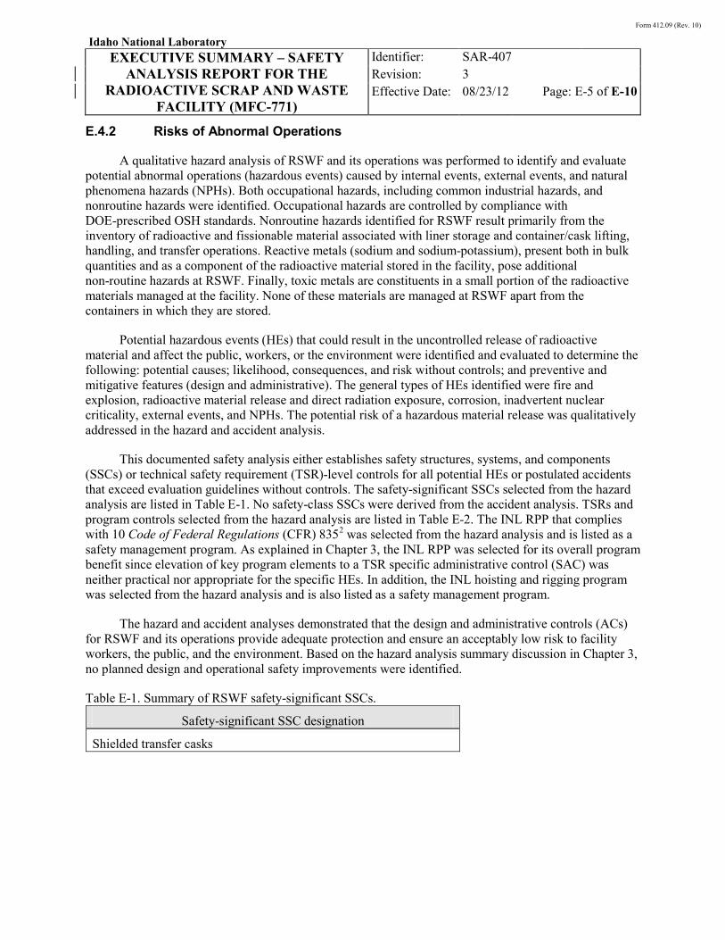
Potential hazardous events (HEs) that could result in the uncontrolled release of radioactive material and affect the public, workers, or the environment were identified and evaluated to determine the following: potential causes; likelihood, consequences, and risk without controls; and preventive and mitigative features (design and administrative). The general types of HEs identified were fire and explosion, radioactive material release and direct radiation exposure, corrosion, inadvertent nuclear criticality, external events, and NPHs. The potential risk of a hazardous material release was qualitatively addressed in the hazard and accident analysis.
This documented safety analysis either establishes safety structures, systems, and components (SSCs) or technical safety requirement (TSR)-level controls for all potential HEs or postulated accidents that exceed evaluation guidelines without controls. The safety-significant SSCs selected from the hazard analysis are listed in Table E-1. No safety-class SSCs were derived from the accident analysis. TSRs and program controls selected from the hazard analysis are listed in Table E-2. The INL RPP that complies with 10 Code of Federal Regulations (CFR) 8352
The hazard and accident analyses demonstrated that the design and administrative controls (ACs) for RSWF and its operations provide adequate protection and ensure an acceptably low risk to facility workers, the public, and the environment. Based on the hazard analysis summary discussion in Chapter 3, no planned design and operational safety improvements were identified.
was selected from the hazard analysis and is listed as a safety management program. As explained in Chapter 3, the INL RPP was selected for its overall program benefit since elevation of key program elements to a TSR specific administrative control (SAC) was neither practical nor appropriate for the specific HEs. In addition, the INL hoisting and rigging program was selected from the hazard analysis and is also listed as a safety management program.
Table E-1. Summary of RSWF safety-significant SSCs.
Safety-significant SSC designation
Shielded transfer casks

Form 412.09 (Rev. 10)
Idaho National Laboratory
EXECUTIVE SUMMARY – SAFETY ANALYSIS REPORT FOR THE
RADIOACTIVE SCRAP AND WASTE FACILITY (MFC-771)
Identifier: Revision: Effective Date:
SAR-407 3 08/23/12 Page: E-6 of E-10
Table E-2. Summary of administrative controls.
Control Type
Container handling limit TSR-level SAC
RSWF in-facility movements TSR-level SAC
Cask seating requirement TSR-level SAC
Container position TSR-level SAC [LCO format]
Staffing requirement TSR-level SAC
Soil excavation control TSR-level SAC
Supplemental radiological control TSR-level SAC [LCO format]
Criticality safety controls TSR-level SAC
Radiation protection program INL safety management program (implements 10 CFR 835)
Hoisting and rigging program INL safety management program (AC 5.400.12)
Emergency preparedness program INL safety management program (AC 5.400.9)
SAC specific administrative control
In addition to the safety-significant SSCs and the ACs cited in Tables E-1 and E-2 above, the following safety analysis commitments were also derived from the hazard analysis:
• Remote liner drilling
• Liner venting/purging
• Procedural requirement to evaluate equipment being utilized near liners
• Procedural requirement to protect unanalyzed liners.
E.4.3 Risks of Postulated Accidents
Based on the hazard analysis, the following representative and bounding accidents were selected for further quantitative analysis:
• Container drop release accident
• Hydrogen explosion/sodium fire release accident
• Vehicle fuel fire release accident with ISC
• Inadvertent criticality accident.
Form 412.09 (Rev. 10)
Idaho National Laboratory
EXECUTIVE SUMMARY – SAFETY ANALYSIS REPORT FOR THE
RADIOACTIVE SCRAP AND WASTE FACILITY (MFC-771)
Identifier: Revision: Effective Date:
SAR-407 3 08/23/12 Page: E-7 of E-10
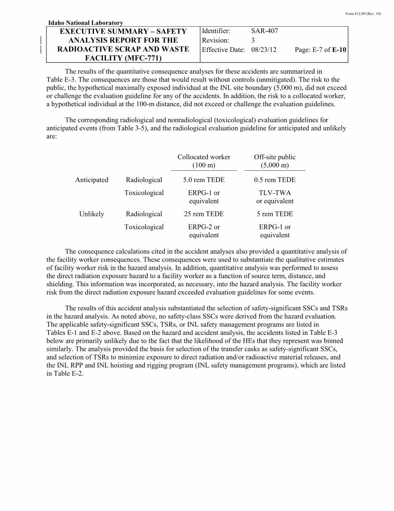
The results of the quantitative consequence analyses for these accidents are summarized in Table E-3. The consequences are those that would result without controls (unmitigated). The risk to the public, the hypothetical maximally exposed individual at the INL site boundary (5,000 m), did not exceed or challenge the evaluation guideline for any of the accidents. In addition, the risk to a collocated worker, a hypothetical individual at the 100-m distance, did not exceed or challenge the evaluation guidelines.
The corresponding radiological and nonradiological (toxicological) evaluation guidelines for anticipated events (from Table 3-5), and the radiological evaluation guideline for anticipated and unlikely are:
Collocated worker
(100 m) Off-site public
(5,000 m)
Anticipated Radiological 5.0 rem TEDE 0.5 rem TEDE
Toxicological ERPG-1 or equivalent
TLV-TWA or equivalent
Unlikely Radiological 25 rem TEDE 5 rem TEDE
Toxicological ERPG-2 or equivalent
ERPG-1 or equivalent
The consequence calculations cited in the accident analyses also provided a quantitative analysis of
the facility worker consequences. These consequences were used to substantiate the qualitative estimates of facility worker risk in the hazard analysis. In addition, quantitative analysis was performed to assess the direct radiation exposure hazard to a facility worker as a function of source term, distance, and shielding. This information was incorporated, as necessary, into the hazard analysis. The facility worker risk from the direct radiation exposure hazard exceeded evaluation guidelines for some events.
The results of this accident analysis substantiated the selection of safety-significant SSCs and TSRs in the hazard analysis. As noted above, no safety-class SSCs were derived from the hazard evaluation. The applicable safety-significant SSCs, TSRs, or INL safety management programs are listed in Tables E-1 and E-2 above. Based on the hazard and accident analysis, the accidents listed in Table E-3 below are primarily unlikely due to the fact that the likelihood of the HEs that they represent was binned similarly. The analysis provided the basis for selection of the transfer casks as safety-significant SSCs, and selection of TSRs to minimize exposure to direct radiation and/or radioactive material releases, and the INL RPP and INL hoisting and rigging program (INL safety management programs), which are listed in Table E-2.

Form 412.09 (Rev. 10)
Idaho National Laboratory
EXECUTIVE SUMMARY – SAFETY ANALYSIS REPORT FOR THE
RADIOACTIVE SCRAP AND WASTE FACILITY (MFC-771)
Identifier: Revision: Effective Date:
SAR-407 3 08/23/12 Page: E-8 of E-10
Table E-3. Summary of accident analysis results.
Accident
Unmitigated consequences, TED,a rem
Collocated worker receptor dose at 100 m
Off-site public receptor dose at 5,000 m
Container drop release
• Base case 1.52E+00 4.60E-02
• Scaled case 9.80E+00 3.36E-01
Hydrogen explosion/sodium fire release 2.98E-01 6.89E-03
Vehicle fuel fire release 3.99E-01 8.61E-03
Inadvertent criticalityb ~95 Footnote “c”
a. TED is the sum of CED plus Deep Dose Equivalent (DDE) from cloud gamma exposure. Cloud gamma exposure was found to be negligible. Therefore, TED is effectively CED. In the comparison to guidelines in the Chapter 3 accident analysis, the results (TED) were compared directly to the guidelines (TEDE).
b. Consequences represent nuclear criticality accident consequence results developed for the Fuel Manufacturing Facility at MFC; the results were used semi-quantitatively to address potential consequences from an RSWF nuclear criticality accident.
c. Per the applicable accident analysis discussion provided in Chapter 3, the dominant pathway for criticality accident consequences is direct radiation. The direct radiation dose at the off-site public receptor location (4,700 m for the FMF analysis) was not explicitly calculated. It is understood, however, that there is essentially no direct radiation dose at this location.
E.5 Organizations
The DOE Idaho Operations Office (DOE-ID) is responsible for all operations at the INL. Battelle Energy Alliance (BEA), LLC, is the current management and operating (M&O) contractor for the INL and is responsible for the operations performed at MFC, including those associated with RSWF.
Organizations conducting work in RSWF are directly accountable to the Nuclear Operations Director for work planning, control, execution, safety, and compliance. The Operations Directorate performs oversight of operations. The Applied Engineering Directorate provides safety analysis and nuclear criticality safety support and personnel.
E.6 Safety Analysis Conclusions
The safety analysis for RSWF and its operations, as documented here, demonstrates that public and worker health and safety and the environment are adequately protected. Protection is provided by the design features of RSWF and by the administrative controls (TSRs) and INL safety management programs that govern RSWF operations as derived from the hazard and accident analysis.

Form 412.09 (Rev. 10)
Idaho National Laboratory
EXECUTIVE SUMMARY – SAFETY ANALYSIS REPORT FOR THE
RADIOACTIVE SCRAP AND WASTE FACILITY (MFC-771)
Identifier: Revision: Effective Date:
SAR-407 3 08/23/12 Page: E-9 of E-10
E.7 SAR Organization
This safety analysis report (SAR) is compliant with the requirements of 10 CFR 830, Subpart B, “Safety Basis Requirements,”3 and is the documented safety analysis (DSA) for RSWF. This document is written in a 17-chapter format that follows the guidelines of DOE-STD-3009-94, “Preparation Guide for U.S. Department of Energy Nonreactor Nuclear Facility Documented Safety Analyses.”4 The TSRs derived from the hazard and accident analyses are presented in a separate TSR document, TSR-407. Chapters in this SAR reference SAR-400, “INL Standardized Safety Analysis Report,”5 and TSR-400, “INL Standardized Technical Safety Requirements,”6
E.8 References
for information applicable to all INL facilities and operations.
1. DOE-STD-1027-92, “Hazard Categorization and Accident Analysis Techniques for Compliance with DOE Order 5480.23, Nuclear Safety Analysis Reports,” Change 1, U.S. Department of Energy, September 1997.
2. 10 CFR 835, “Occupational Radiation Protection,” Code of Federal Regulations, Office of the Federal Register.
3. 10 CFR 830, Subpart B, “Safety Basis Requirements,” Code of Federal Regulations, Office of the Federal Register.
4. DOE-STD-3009-94, “Preparation Guide for U.S. Department of Energy Nonreactor Nuclear Facility, Documented Safety Analyses,” U.S. Department of Energy, Change 3, March 2006.
5. SAR-400, “INL Standardized Safety Analysis Report,” current revision.
6. TSR-400, “INL Standardized Technical Safety Requirements,” current revision.

Form 412.09 (Rev. 10)
Idaho National Laboratory
EXECUTIVE SUMMARY – SAFETY ANALYSIS REPORT FOR THE
RADIOACTIVE SCRAP AND WASTE FACILITY (MFC-771)
Identifier: Revision: Effective Date:
SAR-407 3 08/23/12 Page: E-10 of E-10
INTENTIONALLY BLANK

Form 412.09 (Rev. 10)
Idaho National Laboratory
CHAPTER 2 – FACILITY DESCRIPTION – SAFETY ANALYSIS REPORT FOR THE RADIOACTIVE
SCRAP AND WASTE FACILITY (MFC-771)
Identifier: Revision: Effective Date:
SAR-407 3 08/23/12 Page: 2-1 of 2-50
CHAPTER 2
FACILITY DESCRIPTION

Form 412.09 (Rev. 10)
Idaho National Laboratory
CHAPTER 2 – FACILITY DESCRIPTION – SAFETY ANALYSIS REPORT FOR THE RADIOACTIVE
SCRAP AND WASTE FACILITY (MFC-771)
Identifier: Revision: Effective Date:
SAR-407 3 08/23/12 Page: 2-2 of 2-50
INTENTIONALLY BLANK

Form 412.09 (Rev. 10)
Idaho National Laboratory
CHAPTER 2 – FACILITY DESCRIPTION – SAFETY ANALYSIS REPORT FOR THE RADIOACTIVE
SCRAP AND WASTE FACILITY (MFC-771)
Identifier: Revision: Effective Date:
SAR-407 3 08/23/12 Page: 2-3 of 2-50
CONTENTS
2. FACILITY DESCRIPTION ............................................................................................................ 2-5
2.1 Introduction ........................................................................................................................ 2-5
2.2 Requirements ...................................................................................................................... 2-5
2.3 Facility Overview ............................................................................................................... 2-5
2.4 Facility Structure ................................................................................................................ 2-7
2.4.1 RSWF Liners ................................................................................................ 2-10 2.4.2 Radioactive Material Containers ................................................................... 2-17 2.4.3 Cathodic Protection System .......................................................................... 2-25 2.4.4 Facility Design .............................................................................................. 2-27
2.5 Process Description .......................................................................................................... 2-29
2.5.1 Radioactive Material Overview .................................................................... 2-29 2.5.2 RSWF Process Equipment Overview ........................................................... 2-32 2.5.3 RSWF Operations Overview ........................................................................ 2-44
2.6 Confinement Systems ....................................................................................................... 2-48
2.7 Safety Support Systems .................................................................................................... 2-48
2.8 Utility Distribution Systems ............................................................................................. 2-48
2.9 Auxiliary Systems and Support Facilities ........................................................................ 2-48
2.9.1 Personnel Access Trailer ............................................................................... 2-48 2.9.2 Security System ............................................................................................ 2-49
2.10 References ........................................................................................................................ 2-49
FIGURES
Figure 2-1. RSWF site map. ...................................................................................................................... 2-8 Figure 2-2. RSWF Staging Area. ............................................................................................................... 2-9 Figure 2-3. RSWF 16-in. and 24-in. liners. ............................................................................................. 2-12 Figure 2-4. RSWF 26-in. and 30-in. liners. ............................................................................................. 2-13 Figure 2-5. 16-in. liner with shield plug assembly. ................................................................................. 2-16 Figure 2-6. Pre-1978 paint cans (examples). ........................................................................................... 2-18 Figure 2-7. Liner-in-a-liner overpack configuration. ............................................................................... 2-19
Form 412.09 (Rev. 10)
Idaho National Laboratory
CHAPTER 2 – FACILITY DESCRIPTION – SAFETY ANALYSIS REPORT FOR THE RADIOACTIVE
SCRAP AND WASTE FACILITY (MFC-771)
Identifier: Revision: Effective Date:
SAR-407 3 08/23/12 Page: 2-4 of 2-50
Figure 2-8. RSWF double can configuration (example). ......................................................................... 2-21 Figure 2-9. HFEF-5 double can configuration for EBR-II driver fuel (example). ................................... 2-22 Figure 2-10. RSWF impressed-current CPS. ........................................................................................... 2-26 Figure 2-11. HFEF-5 cask. ....................................................................................................................... 2-34 Figure 2-12. HFEF-14 cask. ..................................................................................................................... 2-35 Figure 2-13. Side view of ISC. ................................................................................................................ 2-37 Figure 2-14. Top view of the ISC. ........................................................................................................... 2-38 Figure 2-15. A top view of TRU-ISC. ..................................................................................................... 2-39 Figure 2-16. Facility transfer container. ................................................................................................... 2-40 Figure 2-17. FTC lift yoke. ...................................................................................................................... 2-41 Figure 2-18. FTC lift yoke translating vertical to horizontal. .................................................................. 2-42 Figure 2-19. FTC list assist skid. ............................................................................................................. 2-43 Figure 2-20. FTC receiving station. ......................................................................................................... 2-44
TABLE
Table 2-1. RSWF liner summary. ............................................................................................................ 2-11

Form 412.09 (Rev. 10)
Idaho National Laboratory
CHAPTER 2 – FACILITY DESCRIPTION – SAFETY ANALYSIS REPORT FOR THE RADIOACTIVE
SCRAP AND WASTE FACILITY (MFC-771)
Identifier: Revision: Effective Date:
SAR-407 3 08/23/12 Page: 2-5 of 2-50
2. FACILITY DESCRIPTION
2.1 Introduction
This chapter describes RSWF and its operations. Chapter 2 focuses on the equipment and facility features necessary to support the hazard and accident analyses presented in Chapter 3. Dimensions given in this chapter for equipment and facility features are nominal and are for information only.
The equipment and operations described in this SAR do not encompass activities associated with the transportation of radioactive and/or fissionable material from RSWF to other facilities performed in accordance with a DOE-approved transport plan or equivalent. Transportation-related activities that may be performed within RSWF and the RSWF Staging Area include container lifting and handling, container movements, and transportation package loading. Such transportation-related activities may be performed separate from, or concurrent with, the operations and activities addressed in this safety basis and PLN-1851, “Transport Plan for the Transfer of Waste Containers between RWMC and INTEC, and RSWF and INTEC,”1
2.2 Requirements
or equivalent.
Design requirements (design codes and standards) that apply to RSWF with respect to the facility description are found in DOE O 420.1B, “Facility Safety.”2
2.3 Facility Overview
Additional design codes, standards, regulations, and DOE orders that were used in the design and evaluation of the RSWF are referred to where applicable in this chapter.
RSWF was approved for construction by the Atomic Energy Commission in 1964. Construction was completed and accepted in February 1965, and the first waste was placed in the site in June 1965. RSWF was designed to provide interim storage for radioactive material that requires shielding to protect workers from the significant gamma radiation fields associated with the material. Today, the RSWF storage capability primarily supports the MFC HFEF, FCF, and Analytical Laboratory hot cell operations. In addition, a limited amount of radioactive material from non-INL facilities (primarily Argonne National Laboratory-East [ANL-E]) is stored at RSWF. Shielding is provided by storing the radioactive material in vertical, carbon-steel “liners” set in soil, with approximately 2 to 4 in. of the liner being above-grade, and by the shield plugs (when necessary) that are integral with the top of the liners.
RSWF currently provides interim storage for spent nuclear fuel (SNF), accountable material, and various radioactive wastes. SNF includes Experimental Breeder Reactor-II (EBR-II) and other experimental nuclear fuels, in the form of metal, oxides, nitrides, and carbides of uranium, plutonium, or mixed uranium-plutonium. In addition to spent fuel and accountable material, various types of radioactive waste (e.g., transuranic [TRU], remote-handled [RH] low level waste [LLW], mixed RH-TRU) are managed at RSWF.

Form 412.09 (Rev. 10)
Idaho National Laboratory
CHAPTER 2 – FACILITY DESCRIPTION – SAFETY ANALYSIS REPORT FOR THE RADIOACTIVE
SCRAP AND WASTE FACILITY (MFC-771)
Identifier: Revision: Effective Date:
SAR-407 3 08/23/12 Page: 2-6 of 2-50
The spent fuel and accountable material is stored at RSWF due to the potentially recoverable quantities of uranium and/or plutonium. Remote-handled mixed and radioactive waste is stored because additional characterization, segregation, and/or treatment are required, and/or because a treatment or disposal facility does not currently exist. Much of the radioactive material stored at RSWF contains reactive sodium and/or toxic metals, thereby making RSWF subject to the hazardous waste regulations of the State of Idaho HWMA and RCRA. As such, RSWF operates under a HWMA/RCRA mixed waste storage permit.3
While the basic facility design of RSWF has remained unchanged since its inception, improvements in facility operational practices have been implemented over the years to enhance the overall performance of RSWF. Prior to 1978, radioactive material to be stored at RSWF was usually packaged in thin-walled steel “paint cans.” Once filled and closed, the cans were typically dropped into the liner and then covered with gravel to provide radiation shielding. In 1978, packaging practices were modified to use a double, nested can (i.e., inner can placed inside an outer can for post 1978 containers), engineered for future retrieval, for radioactive materials to be stored at RSWF. The design of this double can configuration included the capability for controlled lowering of the container (rather than a free-fall drop) into the liner. Closure of liners following placement of the radioactive material container also changed over the years; the use of gravel with a steel cover plate (typical closure before 1978) was replaced by a concrete/steel shield plug assembly, a steel shield plug, or a steel-encased lead plug. In addition, some container configurations included a lead or steel shield plug between the inner and outer can (e.g., HFEF-5 double can).
In 1988, concerns regarding corrosion of the original carbon steel liners led to an overall upgrade of the RSWF. The upgrade began in 1989 and included installation of a new impressed-current CPS; replacement of the original liners with new, cathodically-protected liners; and, relocation of radioactive material from the original non-cathodically-protected liners into the new cathodically-protected liners. Material relocation was determined based on the container type located in the original liner. Liners with radioactive material in single containers (pre-1978) were removed in their entirety and relocated to 24-in., overpack liners. An exception to this process was twenty-one 26-in. (OD) liners installed from 1975-1976 to accommodate waste from the Sodium Loop Safety Facility (SLSF). These liners were provided with passive cathodic protection (upgraded to impressed-current CPS in the early 90s)7 and closed with lead or steel shield plugs (4 or 6 in. long). Although installed before 1978, they were not replaced, nor were the containers relocated during the RSWF upgrade project. The degradation of stainless steel container material is a potential problem for RSWF storage containers. Container materials have been exposed to significant ionizing radiation, temperature changes, and embrittling and gaseous hydrogen embrittlement. Hydrogen is required for hydrogen embrittlement, and hydrogen embrittlement increases with hydrogen gas pressure. Embrittlement of storage containers can have a negative effect on container integrity under certain conditions. Therefore, RSWF outer waste cans (OWCs)/inner waste cans (IWCs) are not opened at RSWF; they are sent to an appropriate facility for disposal or characterization to facilitate disposal.
With a few exceptions, material stored post-1978 consisted of liners with radioactive material in a double can container. These containers were typically opened, and only the container was transferred to a new cathodically-protected standard 16-in. liner. In a few instances, the 16-in. liners were overpacked without removing the double can container.

Form 412.09 (Rev. 10)
Idaho National Laboratory
CHAPTER 2 – FACILITY DESCRIPTION – SAFETY ANALYSIS REPORT FOR THE RADIOACTIVE
SCRAP AND WASTE FACILITY (MFC-771)
Identifier: Revision: Effective Date:
SAR-407 3 08/23/12 Page: 2-7 of 2-50
Currently, RSWF provides interim storage for radioactive waste and other materials in support of hot cell operations at HFEF, FCF, and the Analytical Laboratory. These operations include research and development associated with spent fuel processing, waste form development and demonstration (e.g., metallic and ceramic forms), and other programs and operations as the mission at MFC continues to evolve. Operations performed at RSWF include receipt, container handling, liner loading (storage) and unloading, and cask movement using heavy equipment. Future waste retrieval operations will also support INL remote-handled radioactive waste treatment and disposition activities. RSWF may also be used to store other miscellaneous radioactive materials as directed by DOE.
2.4 Facility Structure
RSWF is a 388-ft-wide and 448-ft-long outdoor facility located at MFC. The facility is 0.5 miles northeast of EBR-II and 4 miles north of U.S. Highway 20, the closest public highway. The facility contains 27 rows of below-grade steel liners of various sizes. Each row contains up to 50 liners on 6-ft centers, giving a potential total capacity of 1,350 storage locations.
RSWF is completely outdoors and is enclosed by a 7-ft-high security fence. Access to RSWF is gained through the personnel trailer (TR-64) via its personnel gate or two chain link vehicle gates (locked) located at the southwest corner and northeast center of the facility. There are no permanent buildings associated with RSWF. An improved road inside RSWF provides vehicle access (e.g., cranes, forklifts, trucks) to the rows of storage liners.
The general slope of the facility (from the center to the outer edges) serves to facilitate run-off of precipitation away from the liners. The elevation at the center of RSWF is approximately 5,120 ft, sloping to approximately 5,117 ft at the fence line. The surrounding land within about 300 ft of the facility is at a lower elevation than the fence line. A facility drainage system, consisting of drainage culverts located on the north, east and west sides of the facility, and at specific locations within the facility, provides for general runoff and diversion of surface water from the facility to the surrounding desert.
Six concrete pads run parallel to three rows of liners at the north end of the facility. The pads were installed to provide a stable surface for transfer equipment (forklift) when access to the liners in other rows is hampered by muddy conditions and/or snow. The only utility interface with other MFC facilities is normal electrical power, which is received from a post across from the Sodium Components Maintenance Shop (SCMS, MFC-793). Electricity is provided to RSWF as a general utility service and supports the CPS and security systems, and the personnel access trailer. There are no other utilities associated with RSWF operations. A site map of RSWF is shown in Figure 2-1.
An additional aspect of RSWF is the RSWF Staging Area, located before the RSWF main storage area along the southeast side of the main access road, which was established in 2010 by the RH-TRU retrieval project. (An equipment storage area is also located along the southwest side of the main access road; however, this equipment storage area is not included within this safety basis.) The RSWF Staging Area was built for the storage of loaded or partially loaded ISCs and FTCs and their transport vehicle storage overnight or until the transport to INTEC could be started. The RSWF Staging Area is an asphalt pad measuring approximately 100 × 200 ft. The area is enclosed entirely by a 9-ft chain link fence. A gate off the main access road allows vehicles or people to enter or exit the staging area from the southwest side, and with its double gates vehicles and people may also enter or exit onto the main access road at the northeast side. A depiction of the staging area4 Figure 2-2 is provided in .

Form 412.09 (Rev. 10)
Idaho National Laboratory
CHAPTER 2 – FACILITY DESCRIPTION – SAFETY ANALYSIS REPORT FOR THE RADIOACTIVE
SCRAP AND WASTE FACILITY (MFC-771)
Identifier: Revision: Effective Date:
SAR-407 3 08/23/12 Page: 2-8 of 2-50
Figure 2-1. RSWF site map.
Form 412.09 (Rev. 10)
Idaho National Laboratory
CHAPTER 2 – FACILITY DESCRIPTION – SAFETY ANALYSIS REPORT FOR THE RADIOACTIVE
SCRAP AND WASTE FACILITY (MFC-771)
Identifier: Revision: Effective Date:
SAR-407 3 08/23/12 Page: 2-9 of 2-50
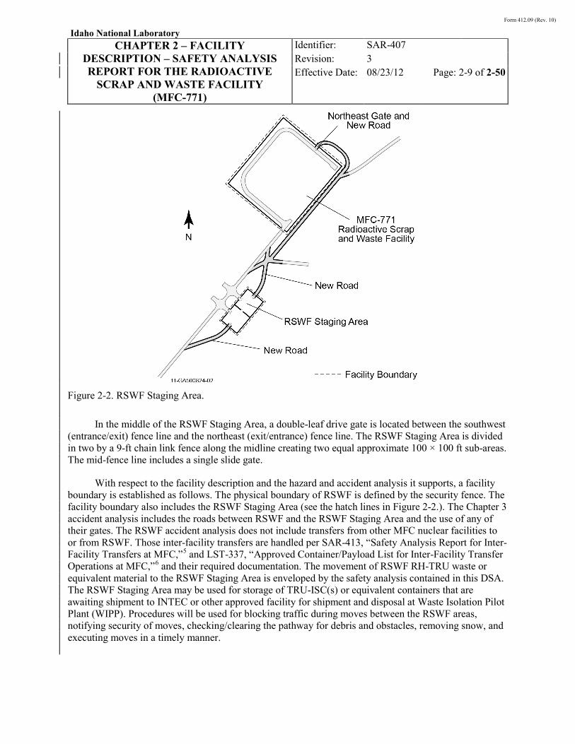
Figure 2-2. RSWF Staging Area.
In the middle of the RSWF Staging Area, a double-leaf drive gate is located between the southwest (entrance/exit) fence line and the northeast (exit/entrance) fence line. The RSWF Staging Area is divided in two by a 9-ft chain link fence along the midline creating two equal approximate 100 × 100 ft sub-areas. The mid-fence line includes a single slide gate.
With respect to the facility description and the hazard and accident analysis it supports, a facility boundary is established as follows. The physical boundary of RSWF is defined by the security fence. The facility boundary also includes the RSWF Staging Area (see the hatch lines in Figure 2-2.). The Chapter 3 accident analysis includes the roads between RSWF and the RSWF Staging Area and the use of any of their gates. The RSWF accident analysis does not include transfers from other MFC nuclear facilities to or from RSWF. Those inter-facility transfers are handled per SAR-413, “Safety Analysis Report for Inter-Facility Transfers at MFC,”5 and LST-337, “Approved Container/Payload List for Inter-Facility Transfer Operations at MFC,”6 and their required documentation. The movement of RSWF RH-TRU waste or equivalent material to the RSWF Staging Area is enveloped by the safety analysis contained in this DSA. The RSWF Staging Area may be used for storage of TRU-ISC(s) or equivalent containers that are awaiting shipment to INTEC or other approved facility for shipment and disposal at Waste Isolation Pilot Plant (WIPP). Procedures will be used for blocking traffic during moves between the RSWF areas, notifying security of moves, checking/clearing the pathway for debris and obstacles, removing snow, and executing moves in a timely manner.

Form 412.09 (Rev. 10)
Idaho National Laboratory
CHAPTER 2 – FACILITY DESCRIPTION – SAFETY ANALYSIS REPORT FOR THE RADIOACTIVE
SCRAP AND WASTE FACILITY (MFC-771)
Identifier: Revision: Effective Date:
SAR-407 3 08/23/12 Page: 2-10 of 2-50
As noted above, there are no permanent structures associated with RSWF. This section, therefore, provides an overview of the storage liners, the radioactive material containers, and the CPS. A brief discussion of the factors given consideration in selection of the site is also provided.
RSWF is a dynamic facility. Both 16- and 26-in. liners will continue to be used for storage and the contents of retrievable waste containers. When necessary, 24-in. liners will be retrieved. 30-in. liners are currently present in RSWF for overpacking and lag storage purposes, but more may be installed as needed.
2.4.1 RSWF Liners
Storage of radioactive material at RSWF is provided by liners that are buried vertically in soil. The liners vary in length and diameter, and consist of a steel pipe with an oversized steel base plate welded to the bottom. The majority of the liners currently in use at RSWF are 16-, 24-, and 26-in. OD pipe. There are also 30-in. OD liners (installed to serve as a contingency for any potential 16-in. or 24-in. overpack needs or lag storage), and 48- and 60-in. OD liners that were fabricated and installed to accommodate non-standard waste packages. A brief description of the liners is provided below. Table 2-1 provides a summary of liner details, while Figure 2-4 and Figure 2-5 provide illustrations of several storage liners. Additional information pertaining to the liners (e.g., materials, welds, dimensions) is provided in SDD-225, “RSWF Storage Liner System Design Description,”7
The liners are constructed of carbon steel and are compatible with the radioactive material stored within.
and the engineering drawings referenced therein.
7 The weld that attaches the base plate to the pipe section was performed in accordance with welding requirements in effect at the time (e.g., INL Welding Manual, ASME Pressure Piping Code), and included visual inspection to ensure acceptability of the weld. For all but the 60-in. liner, the pipe/base plate assembly was hydrostatically tested at 15 psi for fifteen minutes (leakage was determined by a visual examination of the liner) prior to placement in the soil. The 60-in. liner pipe/base plate was hydrostatically tested at 22 psig for 15 minutes. The new 30-in. liners will also be hydrostatically tested at 15 psi for 15 minutes with a quality control representative witnessing the test for RSWF liner fabrications per SDD-225. The fabrication and testing of liners served to ensure that only liners of known integrity were installed at RSWF, since the liners provide the final level of confinement for the radioactive material stored therein.
The liners are positioned vertically in a bore hole drilled 8 in. larger in diameter and 1 in. shorter in length than the liner to be installed (liners are not set in bedrock). Sand was typically placed in the bottom of the soil bore hole prior to insertion of the liner. Once the liner was positioned in the bore hole, the annulus between the liner and soil was backfilled with non-corrosive sand slurry to provide a barrier between the liner and the native soil. The oversized base plate prevents upward migration of the liner and maintains the liner in a vertical orientation in the soil. The liners were placed in the soil so that approximately 2-4 in. of the liner top extended above grade level.

Form 412.09 (Rev. 10)
Idaho National Laboratory
CHAPTER 2 – FACILITY DESCRIPTION – SAFETY ANALYSIS REPORT FOR THE RADIOACTIVE
SCRAP AND WASTE FACILITY (MFC-771)
Identifier: Revision: Effective Date:
SAR-407 3 08/23/12 Page: 2-11 of 2-50
Table 2-1. RSWF liner summary.
Liner Type Length
(in.)
Outside Diameter
(in.)
Wall Thickness
(in.)
Base Plate
Diameter (in.)
Welded (W) or Bolted
(B) Top Plate
Top Plate or Flange Thickness
(in.)
Length of Shield
Plug (in.) Shield Plug Material
Number of Installed Liners
16-in. Standarda 148 16 0.25 18.875 W 0.5 32 Concrete/steel plate 473
16-in. Short 120 16 0.50 18.875 W 0.5 32 Concrete/steel plate 116
24-in. Unflanged 164 24 0.25 26 W 0.625 4 or 6 Steel/lead shot (4-in.) or Steel (6-in.)
401
24-in. Flanged 164 24 0.25 26 B 1.25 NA NA 123
26-in. 156 26 0.25 28 W 0.625 4 Steel/lead shot (4-in.) or Steel (6-in.)
166
30-in. 181.25 30 0.3125 32 B 1.25 NA NA 5
48-in. 45.75 48 0.375 56 W 0.75 NA NA 2
60-in. 133 60.75 0.375 64 W 1.0 NA NA 1
Total Liners 1,287
Radiation Monitoring Tubes
4.5-in. Radiation Monitoring Tube
148 4.5 0.237 6.5 B 0.625 NA NA 13
a. Six of the standard 16-in. liners are designated “corrosion surveillance liners.” One of the corrosion surveillance liners is retrieved every four years and inspected for evidence of corrosion. There were originally 10 liners that were earmarked for this purpose. To date (May 2012), four liners have been pulled and inspected (in 1997, 2001, 2005, and 2009), leaving six corrosion surveillance liners remaining.
Form 412.09 (Rev. 10)
Idaho National Laboratory
CHAPTER 2 – FACILITY DESCRIPTION – SAFETY ANALYSIS REPORT FOR THE RADIOACTIVE
SCRAP AND WASTE FACILITY (MFC-771)
Identifier: Revision: Effective Date:
SAR-407 3 08/23/12 Page: 2-12 of 2-50
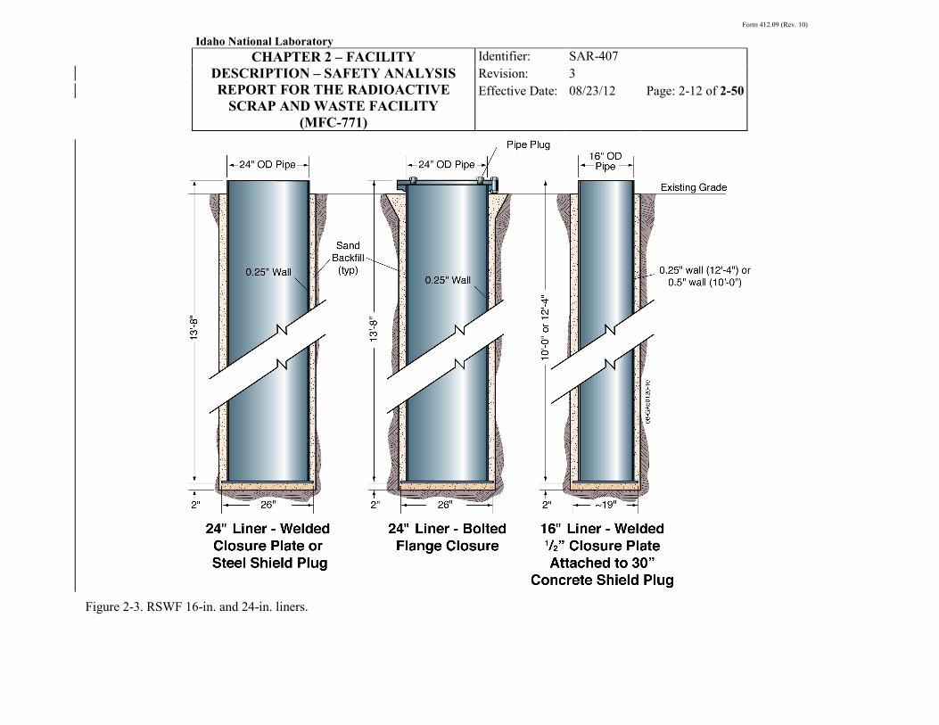
Figure 2-3. RSWF 16-in. and 24-in. liners.

Form 412.09 (Rev. 10)
Idaho National Laboratory
CHAPTER 2 – FACILITY DESCRIPTION – SAFETY ANALYSIS REPORT FOR THE RADIOACTIVE
SCRAP AND WASTE FACILITY (MFC-771)
Identifier: Revision: Effective Date:
SAR-407 3 08/23/12 Page: 2-13 of 2-50
Figure 2-4. RSWF 26-in. and 30-in. liners.

Form 412.09 (Rev. 10)
Idaho National Laboratory
CHAPTER 2 – FACILITY DESCRIPTION – SAFETY ANALYSIS REPORT FOR THE RADIOACTIVE
SCRAP AND WASTE FACILITY (MFC-771)
Identifier: Revision: Effective Date:
SAR-407 3 08/23/12 Page: 2-14 of 2-50
Once a radioactive material container has been placed in the liner, the liner is closed. The method of closure depends upon the size of the liner and the radiation level associated with the material stored in the liner. Closure devices vary in design depending on the liner size and shielding requirement, and consist of steel/concrete plugs, steel-encased lead, or a solid steel plug. In some liner configurations, liner closure is completed by simply bolting a gasketed steel cover to the top of a flanged liner. Liner closure devices include welded lifting lugs to allow handling and placement. Closure device welds are also examined at installation to ensure weld acceptability. In addition, periodic inspection is performed to identify any cracks, corrosion, and deterioration on the exposed portions of the liners. Each liner also has a unique identification number corresponding to its location in the facility. In addition, all liners are connected to a CPS in order to minimize external corrosion.
The liners and closure devices (shield plugs, cover plate, etc.) typically have no provision for sampling, venting or inspecting internal conditions once the liner is closed.
In addition to the liners used for storage of radioactive material, other components installed in the soil at RSWF include radiation monitoring tubes and corrosion surveillance liners. The radiation monitoring tubes are 4.5-in. carbon steel liners, located at various locations across RSWF, used for annual monitoring of below-grade radiation. The corrosion surveillance liners are standard 16-in. liners that were fabricated, installed, and cathodically-protected in the same manner as the 16-in. storage liners, but not loaded with radioactive material. One of the corrosion surveillance liners is retrieved every four years for corrosion inspection. To date, there are six of the ten corrosion liners originally installed still in place. RSWF liner work has also included a 2010 independent corrosion assessment of the internal surfaces of 24-in. liners.8
Trapped moisture in the relocated 16-in. steel liners and radiation degradation can cause dissimilar radiation-induced stress corrosion at the associated steel bottom of the 24-in. welds used to hold the old-style RSWF 16-in. liners. This has been studied to determine if saturated soil clinging to the 16-in. steel containers previously stored within 24-in. liners resulted in corrosion-related damage to the steel liner, bottom plate, and their weld connection. The conclusions from the inspection of liners FF-8, FF-15, FF-28, and HH-3 were detailed in Reference
8, which states: “Results of the visual inspection showed that the steel liners and their associated bottom plates are in good condition. There were no noted instances of corrosion damage affecting the integrity of either the inspection steel liners, end plates, or their associated welds.” The corrosion engineer recommended further analysis by a structural engineer to verify the bottom plate welds have adequate strength to support the forces required to remove the liners from the ground. The follow-on analysis by the structural engineer documents that the weld on the bottom of the 16-in. liners has sufficient strength to conclude that the weld should hold up to 194,000 lb (194 kips). The demand capacity relationship (D/C) is based on a 30 kip applied load, and the 194 kip allowable load results in a D/C of 0.024.9
Overall, the relocated 16-in. liners have been overpacked into 24-in. liners. Prior to retrieval, they are visually examined using a remote camera. When they are lifted, the lift is hold tested prior to moving, and the bottom of the 24-in. liner is visually inspected. These measures and the radiation protection program (e.g., monitoring) provide the mechanism to properly handle the overpacked 16-in. liners for retrieval at RSWF.
A D/C of 0.024 is acceptable.
Form 412.09 (Rev. 10)
Idaho National Laboratory
CHAPTER 2 – FACILITY DESCRIPTION – SAFETY ANALYSIS REPORT FOR THE RADIOACTIVE
SCRAP AND WASTE FACILITY (MFC-771)
Identifier: Revision: Effective Date:
SAR-407 3 08/23/12 Page: 2-15 of 2-50
2.4.1.1 16-in. Liners. Two types of 16-in. liners (592 total) are used at RSWF. The standard 16-in. (OD) liner is carbon steel pipe, 12 ft, 4 in. in length. The other version of the 16-in. liner is carbon steel pipe, 10 ft in length. The shorter liner was installed where insufficient soil depth existed for installation of the longer liner. Closure of the 16-in. liners is completed with a concrete/steel shield plug assembly that is welded to the top of the liner. The diameter of the shield plug assembly is 14.75 in. or 15.25 in. OD (to fit the different liner inner diameters), and consists of a 0.5-in. steel plate and 31.5 in. of concrete. The bottom of the shield plug assembly includes a provision for connection of the lifting bail that is attached to the radioactive material container stored in the liner (the lifting bail is used to allow for ease in future container retrieval). A concrete/shield plug assembly is illustrated in Figure 2-5.
2.4.1.2 24-in. Liners. The 24 in. (OD) liners (539 total) were installed during the RSWF upgrade project to store the original 16-in. liners (legacy liners) that were relocated during the RSWF upgrade project. They are constructed of carbon steel pipe and are 13 ft, 8 in. in length. The 24-in. liners are closed with a bolted or welded steel cover plate, or a welded steel shield plug (6 in. thick by 23 in. OD) or steel-encased lead shield plug (4 in. thick by 23 in. OD). A solid neoprene gasket provides a seal between the liner and the cover plate in the bolted configuration.
In 1988, three original 16-in. liners were observed to have galvanic corrosion, and others that are now in the 24-in liners could have continued to corrode to failure. Therefore, the retrieval of these liners is being managed by shipping the 24-in. liner to INTEC. The RSWF CPS inhibits corrosion on the external surfaces of the carbon steel liners. This type of system does not, however, protect against internal corrosion that may result from moisture inside the liner. The IWC may be corroded, so no credit is taken for it when retrieving translocated 24-in. liners.
2.4.1.3 26-in. Liners. Twenty-one 26-in. (OD) liners were installed in 1975-1976 to accommodate waste from SLSF. These liners were provided with passive cathodic protection and closed with lead or steel shield plugs (4 in. or 6 in. long). Although installed before 1978, they were not replaced nor were the containers relocated during the RSWF upgrade project. During the RSWF upgrade project, the 26-in. liners were converted from passive to active cathodic protection as documented in SDD-225, which states, “upgraded to impressed current protection.” Additional 26-in. liners were also installed during the RSWF upgrade, resulting in a total of 166. The 26-in. liners are constructed of carbon steel pipe and are 13 ft in length. Closure is completed with a welded steel plug.
2.4.1.4 30-in. Liners. Five 30-in. (OD) liners were installed for the purpose of accommodating 24-in. overpack liners and may be used for lag storage of smaller diameter liners. Additional lag storage liners may be installed in the future based on need. These 30-in. liners are constructed of carbon steel and are 15 ft, 1 in. in length. They are closed with a 1.25-in.-thick steel cover that is bolted to the flanged liner. A solid neoprene gasket provides a seal between the liner and the cover plate.
2.4.1.5 48-in. Liners. Two 48-in. (OD) liners were installed in 2003 to store EBR-II nuclide traps. They are approximately 46 in. long, constructed of carbon steel, and closed with a 0.75-in.-thick carbon steel plate welded to the top of the liner.
2.4.1.6 60-in. Liner. One 60-in. (OD) liner, installed in 1978, is used to store an EBR-II cold trap. The carbon steel liner is 11 ft long and closed with a cover shield consisting of a concrete/steel plate assembly, which includes a 0.5-in. vent pipe.

Form 412.09 (Rev. 10)
Idaho National Laboratory
CHAPTER 2 – FACILITY DESCRIPTION – SAFETY ANALYSIS REPORT FOR THE RADIOACTIVE
SCRAP AND WASTE FACILITY (MFC-771)
Identifier: Revision: Effective Date:
SAR-407 3 08/23/12 Page: 2-16 of 2-50
Figure 2-5. 16-in. liner with shield plug assembly.

Form 412.09 (Rev. 10)
Idaho National Laboratory
CHAPTER 2 – FACILITY DESCRIPTION – SAFETY ANALYSIS REPORT FOR THE RADIOACTIVE
SCRAP AND WASTE FACILITY (MFC-771)
Identifier: Revision: Effective Date:
SAR-407 3 08/23/12 Page: 2-17 of 2-50
2.4.1.7 4.5-In. Radiation Monitoring Tubes. Thirteen 4.5-in. (OD) liners are installed in the facility and referred to as radiation monitoring tubes. These empty liners are 12 ft, 4 in. long, and are closed with a 0.625-in.-thick steel plate bolted to the top of the flanged liner. They are used for annual monitoring of below-grade radiation to help detect increases in subsurface radioactivity that may indicate potential breaches in storage liners.
2.4.2 Radioactive Material Containers
Prior to 1978, radioactive material destined for storage at RSWF was usually placed in steel cans referred to as paint cans. The paint cans were not pre-engineered for retrieval and were typically transferred to RSWF as a single can (although sometimes a smaller paint can was placed in a larger paint can). Beginning in 1978, a double-can configuration (loaded inner can placed in an outer can) was the standard configuration used for storage at RSWF. This configuration included a provision for future retrieval and handling, with the intent of providing a double barrier to the potential release of radioactive and hazardous constituents to the environment while in storage at RSWF. Other, non-standard packages/containers, providing at least two barriers for the material stored inside, have also been stored at RSWF.
As discussed in Section 2.3, concerns regarding liner corrosion resulted in the relocation of material/containers from the original non-cathodically-protected liners into new cathodically-protected liners. Liners with paint cans (pre-1978) were removed in their entirety and relocated to new, 24-in. overpack liners. Liners with radioactive material packaged in double cans (i.e., since 1978) were typically opened and only the container was transferred to a new cathodically-protected 16-in. liner. Approximately twenty of the legacy liners containing double cans were relocated in their entirety to new overpack liners. The contents of the original 26-in. liners (SLSF cans) and the 60-in. liner (cold trap) were not relocated because these liners had been cathodically protected since their installation. The upgrade project resulted in the following current confinement configurations: 1) a liner-within-a-liner and, 2) a double can within a liner, and 3) non-standard packages within a liner.
A description of the containers used to package radioactive material for storage at RSWF is provided in the following subsections. There are several configurations of an inner can (used in the double can package) to accommodate the various forms of the radioactive material stored within (e.g., hot cell waste, accountable material, intact EBR-II fuel and subassemblies). Therefore, the descriptions provided herein are intended to be representative of the types of containers used, but not all-inclusive. Additional information on the containers used at RSWF, including dimensions and materials of construction, is included in INL/INT-08-14180, “Criticality Safety Evaluation for the Radioactive Scrap and Waste Facility.”10
2.4.2.1 Paint Cans (pre-1978). The containers used prior to 1978 consisted primarily of a steel can, 6 ft long and 11.25 in. in diameter. The can was constructed of a standard 5-gal, 22-gauge steel pail, which was closed with a standard 16-lug, foam-rubber gasketed cover. The pail was constructed without its usual bottom, and the outside was extended to the overall length of 6 ft by welding on a 20-gauge steel tube with a welded side seam and bottom. Other paint can containers included shorter, steel lug-closed cans that fit inside the 6-ft container. Typical pre-1978 paint cans are shown in
Figure 2-6.11,12

Form 412.09 (Rev. 10)
Idaho National Laboratory
CHAPTER 2 – FACILITY DESCRIPTION – SAFETY ANALYSIS REPORT FOR THE RADIOACTIVE
SCRAP AND WASTE FACILITY (MFC-771)
Identifier: Revision: Effective Date:
SAR-407 3 08/23/12 Page: 2-18 of 2-50
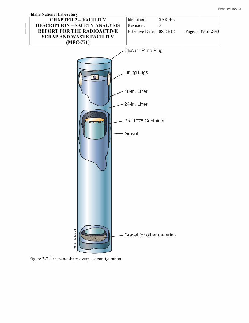
Once filled and closed, the loaded paint can was transferred to RSWF and dropped into a liner. Liners typically contained several inches of sand, gravel, or other material to cushion the fall of the container. In addition, plastic bags attached to the inside of the liner were also used at times to minimize potential contamination spread during liner loading activities. As discussed in Section 2.3, liners with radioactive material packaged in this configuration were removed in their entirety and relocated to cathodically protected 24-in. liners during an upgrade of the RSWF, resulting in a liner/liner configuration, described further in Section 2.4.3. The “liner-in-a-liner” storage configuration is shown in Figure 2-7.
Figure 2-6. Pre-1978 paint cans (examples).
Form 412.09 (Rev. 10)
Idaho National Laboratory
CHAPTER 2 – FACILITY DESCRIPTION – SAFETY ANALYSIS REPORT FOR THE RADIOACTIVE
SCRAP AND WASTE FACILITY (MFC-771)
Identifier: Revision: Effective Date:
SAR-407 3 08/23/12 Page: 2-19 of 2-50
Figure 2-7. Liner-in-a-liner overpack configuration.

Form 412.09 (Rev. 10)
Idaho National Laboratory
CHAPTER 2 – FACILITY DESCRIPTION – SAFETY ANALYSIS REPORT FOR THE RADIOACTIVE
SCRAP AND WASTE FACILITY (MFC-771)
Identifier: Revision: Effective Date:
SAR-407 3 08/23/12 Page: 2-20 of 2-50
2.4.2.2 Double Can Configuration. Since 1978, the standard container used for storage of material at RSWF has been a double, nested can. Several variations of the double can package are used to contain the waste forms and radioactive materials (e.g., SNFs, in-cell radioactive waste, treatable mixed waste, and other radioactive material) stored at RSWF. The specific package is a function of the originating facility and the radioactive material being stored. In addition to the inner and outer cans, EBR-II spent fuel (driver and blanket elements) and EBR-II subassemblies are stored in a “basket,” which provides spacing of the elements or subassemblies prior to placement in the inner can. The primary double can containers are the HFEF-5 can (sized for storage in a 16-in. liner), and the SL can and RH-TRU can, (both of which are sized for storage in a 26-in. liner). These cans are designed to fit in the HFEF-5 and HFEF-14 shielded transfer casks, respectively. Other non-standard packages also provide double confinement of radioactive material (e.g., nuclide and cold traps stored in the 48-in. and 60-in. liners).
The 16-in. cans stored in RSWF prior to 1978 without cathodic protection have been overpacked in a 24-in. liner, and the pre-1978 16-in. canisters had rust and may not provide the double-can configuration. As a result, RSWF personnel have developed a method to extract and send the entire 24-in. liner to the waste handling facility. Removals are not completed for cans that are corroded. Measures to determine corrosion include radiation monitoring, remote camera external examination, and load testing of canisters prior to complete removal from a liner. A generic double can configuration is shown in Figure 2-8. Descriptions of some of the double can configurations are provided in the following subsections.
2.4.2.2.1 HFEF-5 Can—The HFEF-5 outer can has a cylindrical 14-gauge stainless steel body, 73.5 in. long and 12.75 in. OD. The bottom plate of the can is 0.25 in. thick. The top of the can has a built-in support ring that is used for attaching the lid. The lid is a 0.25-in.-thick circular plate with a 2-in.-long, 14-gauge side wall to enable seal-welding the lid to the outer can support ring. The lid has a block and lifting cable pre-installed to enable lifting and moving the entire payload/inner/outer can configuration after the lid is welded on and inspected. The HFEF-5 inner container configuration varies, depending on the material being packaged or loaded (e.g., fuel elements, waste, subassemblies, etc.). The following subsections describe common HFEF-5 inner can configurations.10,13
Figure 2-9 An example of an HFEF-5
can configuration for EBR-II driver fuel elements is shown in .

Form 412.09 (Rev. 10)
Idaho National Laboratory
CHAPTER 2 – FACILITY DESCRIPTION – SAFETY ANALYSIS REPORT FOR THE RADIOACTIVE
SCRAP AND WASTE FACILITY (MFC-771)
Identifier: Revision: Effective Date:
SAR-407 3 08/23/12 Page: 2-21 of 2-50
Figure 2-8. RSWF double can configuration (example).

Form 412.09 (Rev. 10)
Idaho National Laboratory
CHAPTER 2 – FACILITY DESCRIPTION – SAFETY ANALYSIS REPORT FOR THE RADIOACTIVE
SCRAP AND WASTE FACILITY (MFC-771)
Identifier: Revision: Effective Date:
SAR-407 3 08/23/12 Page: 2-22 of 2-50
Figure 2-9. HFEF-5 double can configuration for EBR-II driver fuel (example).
Form 412.09 (Rev. 10)
Idaho National Laboratory
CHAPTER 2 – FACILITY DESCRIPTION – SAFETY ANALYSIS REPORT FOR THE RADIOACTIVE
SCRAP AND WASTE FACILITY (MFC-771)
Identifier: Revision: Effective Date:
SAR-407 3 08/23/12 Page: 2-23 of 2-50
EBR-II Fuel Storage Cans/Fuel Baskets
1. Fuel Pin Baskets.
• Mk-IICS Fuel Pin Basket. Holds up to 93 driver elements (Mk-II series elements). Two loaded Mk-IICS baskets can be stacked axially inside a FSC.
Fuel pin baskets are constructed of aluminum with a center 1-in. Schedule 40 pipe welded to a 1/8-in.-thick base plate. Two circular spacer plates are welded to the center pipe. The two spacer plates contain a circular pattern of equally-spaced holes for positioning EBR-II driver or blanket elements. Fuel elements exhibiting a breach in the cladding or that had suspect cladding integrity were placed in a sealed metal tube prior to loading into the fuel pin basket. The fuel pin baskets range in length from 28 in. to 61 in. (the shorter basket is used for driver elements while the longer basket is used for blanket elements), with an OD of 9.75 in. Once loaded, the fuel pin baskets are placed in a fuel storage can (FSC). The fuel pin baskets used at RSWF are:
• Mk-III Fuel Pin Basket. Holds up to 62 driver elements (Mk-III, Mk-IIIA, Mk-IV, or experimental elements). Two loaded Mk-III baskets can be stacked axially inside a FSC.
• Blanket Fuel Pin Basket. Holds up to 57 blanket elements. One loaded basket was placed in a FSC (later in a blanket storage can [BSC], which is a slightly longer version of the FSC described herein).
2. Blanket Subassembly Basket.
3.
The EBR-II blanket subassembly basket is similar in design and shape to the fuel element baskets, except it is designed to hold six chopped EBR-II blanket subassemblies (a variation on the design can hold five subassemblies) and is constructed of stainless steel. Once loaded, the blanket subassembly basket is placed inside a BSC.
Fuel and Blanket Storage Cans (FSC/BSC).
4.
The FSC is a 14-gauge carbon steel can, 62 in. long and 10 in. in diameter. The can is seal-welded and leak-tested. A top closure flange is welded to the top of the can wall. The bolted lid is a 0.375-in.-thick plate, 11.75 in. OD, that seals the FSC container using a Grafoil gasket between the lid and the can top closure flange. The BSC is similar to the FSC except its length is 64 in. to accommodate the longer blanket elements.
Shield Plugs.
Four-Inch Fuel Storage Can/Fuel Storage Basket
The shield plug used in the FSC assembly is a lead-filled plug 9 in. long. The shield plug used in the BSC is a lead-filled plug 8 in. long. Both shield plugs are installed on top of the inner can, prior to closure of the outer can.
1. Four-Inch Fuel Storage Basket (FIFSB). The FIFSB is an aluminum tube 62 in. long, 3.5 in. OD, with a 0.125-in. wall thickness. The bottom of the basket is a welded plate, 0.125 in. thick. The four-inch storage basket is used for storage of loose irradiated EBR-II fuel elements (any type) and miscellaneous fissionable material. Once loaded, the FIFSB is placed inside a four-inch fuel storage can (FIFSC).

Form 412.09 (Rev. 10)
Idaho National Laboratory
CHAPTER 2 – FACILITY DESCRIPTION – SAFETY ANALYSIS REPORT FOR THE RADIOACTIVE
SCRAP AND WASTE FACILITY (MFC-771)
Identifier: Revision: Effective Date:
SAR-407 3 08/23/12 Page: 2-24 of 2-50
2. Four-Inch Fuel Storage Can (FIFSC).
3.
The FIFSC is a stainless steel 4-in. Schedule 40 pipe with a top flange and bottom plate. The inside dimensions of the pipe are 64.5 in. long and 4 in. OD. The top lid is a 0.75-in.-thick plate that is bolted to a top flange welded to the top of the pipe. The top closure flange is 11.75 in. OD and 1 in. thick, which along with an 11.75-in. OD bottom support ring and positioning spacers welded to the pipe, serves to support and center the FIFSC inside an outer can. Closure of the FIFSC includes a Grafoil gasket between the flange and lid. Once loaded, the FIFSC is installed inside an outer waste can (HFEF-5 can).
FIFSC Shield Plug.
2.4.2.2.2 HFEF-14 Containers—Double can containers transferred using the HFEF-14 cask include the Sodium Loop Can and the TRU-RH Can.
The lead-filled shield plug used in the FIFSC configuration is 6.3 in. long.
10,14
Sodium Loop Can/Cask Liner Container
A description of these container configurations is provided in the following subsections.
1. Sodium Loop (SL) Can.
2.
The SL Can (also known as the SLSF waste disposal can) is used for large oversized remote-handled HFEF metallic waste that is too big to fit in other containers. This inner waste can is a cylindrical 11-gauge stainless steel container 21 in. OD that is 125 in. long. The bottom plate is 1 in. thick. The top of the container incorporates a reinforcing ring/flange to enable bolting a 1-in.-thick stainless steel lid to the container.
Shield Plug.
3.
A steel-encased lead shield plug, 4.25 in. long, is installed on top of the SL can lid, inside the outer container, to provide shielding during container handling and transfer.
Cask Liner Container.
TRU-RH Can
This outer waste can is a cylindrical 11-gauge carbon steel can 132 in. long and 22.5 in. OD. The bottom plate of the can is 1 in. thick. The top of the can has a built-in reinforced ring that is used for attaching the lid. The steel lid is 1.5 in. thick, with 4-in.-long sides to enable seal welding the side of the lid to the side of the cask liner container reinforcing top ring. The lid also has a center tapped hole in the top surface to attach handling grapples for movement of the loaded container.
1. Inner Can.
2.
This inner container is stainless steel with 14-gauge wall thickness. The can is 31 in. long and 20 in. inner diameter, flanged at the top. The lid is a 0.50-in.-thick plate that is bolted to the flange. The container is closed using a gasket between the lid and top closure flange. The outer diameter of the top lid is 21 in. Up to three loaded inner cans can be stacked end-to-end in an outer waste can.
TRU-RH Can Shield Plug.
3.
The lead-filled shield plug is 4.25 in. long and 21 in. OD.
Outer Can. The outer container is a cylindrical 11-gauge stainless steel can body, 104 in. long and 23 in. OD. The bottom plate of the can is 1 in. thick. The top of the can has a built-in support ring that is used for attaching the transfer sleeve and for attaching the lid. The lid is a 0.75-in.-thick circular plate that is seal-welded to the support ring.

Form 412.09 (Rev. 10)
Idaho National Laboratory
CHAPTER 2 – FACILITY DESCRIPTION – SAFETY ANALYSIS REPORT FOR THE RADIOACTIVE
SCRAP AND WASTE FACILITY (MFC-771)
Identifier: Revision: Effective Date:
SAR-407 3 08/23/12 Page: 2-25 of 2-50
2.4.3 Cathodic Protection System
External corrosion of the carbon steel liners at RSWF is inhibited through the use of an impressed-current CPS. The RSWF CPS uses impressed current from rectifiers, which convert alternating current (AC) electric power to low-voltage direct current (DC) power. The negative lead of the rectifier is attached to the structure to be protected (the liner in this case) and the positive lead is connected to an anode. The DC current from the rectifier flows from the anode through the soil to the liners, and then returns to the rectifier through a liner header wire. Direct current is “impressed” onto the surface of the liners, which shifts the electric potential of the liners in the active (negative) direction, thereby inhibiting corrosion of the external surface of the liners. The liner/anode/rectifier connection is illustrated in Figure 2-10. The RSWF CPS, including the basis for its need, is described below. Additional detail, including hardware (wiring, junction boxes, reference electrodes, physical location and layout, principles of operation, and surveillance and maintenance activities), can be found in SDD-225.7
The need for protection of the liners was determined in 1988, when three liners removed from the ground at RSWF were found to show evidence of varying levels of corrosion, ranging from penetration of the liner wall to fairly good condition. Soil samples obtained from adherent soil on the removed liners, as well as four other locations throughout RSWF, were analyzed for pH, chlorides, sulfates, and specific conductance. The corrosive activity of RSWF soil was categorized as ranging from extreme to moderate, based on ranges of resistivity. However, the report did not correlate corrosive activity with corrosion rate. The results were used by CH2M-Hill to develop a preliminary design for the cathodic protection of the RSWF liners. A subsequent investigation was performed by CH2M-Hill to determine the resistivity of the soil throughout the RSWF in support of the design of a CPS for the liners at the facility. The investigation consisted of 90 soil resistivity measurements, using the “Wenner” four-pin method, at average depths of 2.5, 5.0, 10.0, and 15.0 ft. The measurements were used by CH2M-Hill in design development for the RSWF impressed-current CPS. The system design included the recommendations of the National Association of Corrosion Engineers (NACE) RP-0285.”15
The RSWF CPS includes twelve pad-mounted rectifiers that convert 480-volt, three-phase power (supplied from MFC-799) to a DC output. Six of the rectifiers are installed on the east end of the liners, and six are installed on the west end of the liners, providing six rectifier pairs that share the connected load. Each rectifier pair supplies positive DC current to two to six rows of anodes, while two to eight liner rows return negative DC current to the rectifier pair.
Installation of the RSWF impressed-current CPS was completed as part of the RSWF Upgrade project that began in 1989.
The anodes utilized in the RSWF CPS are a linseed-oil-impregnated graphite type. Anodes are located equidistant between liner rows such that typically one anode serves four liners (two liners from each parallel row). There are 24 rows of generally 24-26 anodes per row. Anodes are installed in holes augured approximately 12-in. in diameter to a depth established by the anode type. The installed anodes are surrounded by a non-corrosive coke breeze material, and are replaced as needed.
As discussed above, the RSWF CPS inhibits corrosion on the external surfaces of the carbon steel liners. This type of system does not, however, protect against internal corrosion that may result from moisture inside the liner. Of particular concern is moist soil adhering to the outside of the 16-in. legacy liners that were over-packed into 24-in. liners. Internal corrosion is a concern because of the potential reduction in liner integrity and because of the hydrogen generated from the reaction of iron with water. A

Form 412.09 (Rev. 10)
Idaho National Laboratory
CHAPTER 2 – FACILITY DESCRIPTION – SAFETY ANALYSIS REPORT FOR THE RADIOACTIVE
SCRAP AND WASTE FACILITY (MFC-771)
Identifier: Revision: Effective Date:
SAR-407 3 08/23/12 Page: 2-26 of 2-50
visual inspection of the liners is performed prior to loading to ensure the absence of visible water and the absence of water (e.g., snow) on shield plugs prior to installation in the liner.
Figure 2-10. RSWF impressed-current CPS.

Form 412.09 (Rev. 10)
Idaho National Laboratory
CHAPTER 2 – FACILITY DESCRIPTION – SAFETY ANALYSIS REPORT FOR THE RADIOACTIVE
SCRAP AND WASTE FACILITY (MFC-771)
Identifier: Revision: Effective Date:
SAR-407 3 08/23/12 Page: 2-27 of 2-50
2.4.4 Facility Design
This section discusses RSWF with respect to withstanding postulated evaluation basis natural phenomena events and potential loads important to the safety analysis. The original plans for RSWF included the following considerations:
• The area was selected and would be further improved to provide proper drainage to eliminate chances of flooding by surface water runoff under any foreseeable conditions. Such improvements included addition of soil to the site to increase elevation above surrounding area (10:1 slope).
• All radioactive materials placed in RSWF would be placed in metal containers prior to transfer to the facility; containers included 20-gauge steel pails 6 ft long by 11.5 in. in diameter (smaller pails were also used, and were loaded into a 6-ft-long container once filled). The 6-ft container would meet the leak tightness specifications of standard 5-gallon ICC Rule 40 pails, but were not considered high-integrity containers suitable for long-term storage.
• “Post-holes” would be lined with 0.25-in.-thick wall steel pipe, closed at the bottom with a welded steel plate.
• Steel liners would contain a layer (up to 6 in.) of loose dirt, clay, or bentonite at the bottom to reduce the impact on the bottom cover from dropping the container into the liner during loading. A steel cover would then be welded onto the top of the liner. The liners were to be designed to withstand any pressure buildup due to temperature rise in the contents.
• Liner rows would be built on 12-ft centers, and liners within a row would be built on 6-ft centers.
• With respect to NPHs, selection of the facility location included consideration of pertinent environmental characteristics, such as geologic, flood, groundwater, and general soil conditions.
Design and construction information associated with the current RSWF storage liner system, including the liners and CPS, is included in the RSWF SDD (Reference 7). Potential natural phenomena threats or accident initiators relevant to the RSWF safety analysis are identified and discussed in Chapter 1, “Site Characteristics.” The current design and evaluation criteria for NPHs at the INL are summarized in SAR-400, Chapter 1, “Site Characteristics.”16
2.4.4.1 Seismic Design. Damage from seismic events results from differential movement in a structure. Because of the decoupled nature of the RSWF liner system, in that each of the storage liners is independent of the other liners, the facility is characterized by numerous small structures rather than a single large structure. The relatively compact size of each liner, the design and materials of construction, and placement method (installed entirely in soil, and never in bedrock) make it improbable that seismic motion of adjacent soils could generate forces sufficient to damage a storage liner. A structural evaluation of the RSWF liners has been performed, including the capability of the liners to withstand the loads and forces associated with a Performance Category (PC)-2 seismic event.
Pertinent NPH design or analysis criteria for RSWF are summarized in the following subsections.
17 The evaluation included the effects of differential displacement, mechanical loading (i.e., horizontal and vertical vibration of the liner and container stored within), and seismic excitation of the soil in which the liners are set. The results of the evaluation indicate that the seismic-induced differential displacement is not a concern for the liners,

Form 412.09 (Rev. 10)
Idaho National Laboratory
CHAPTER 2 – FACILITY DESCRIPTION – SAFETY ANALYSIS REPORT FOR THE RADIOACTIVE
SCRAP AND WASTE FACILITY (MFC-771)
Identifier: Revision: Effective Date:
SAR-407 3 08/23/12 Page: 2-28 of 2-50
primarily because of the liner size (small relative to the length of a seismic wave). The evaluation also concluded that mechanical loading effects, due to seismic-wave-induced vibration, are not expected to result in liner failure. With respect to seismic excitation of the soil, the evaluation indicates that under saturated soil conditions, a PC-2 seismic event could cause soil liquefaction at RSWF. During soil liquefaction, liner flotation is possible if the weight of the liner and its contents is less than the corresponding buoyancy force of the loaded liner in the soil.
2.4.4.2 Extreme Wind Design. Extreme wind loads are not a concern for RSWF liners because they are underground.
2.4.4.3 Volcanic Design. Volcanic hazards include lava flow, ground deformation (fissures, uplift, subsidence, etc.), volcanic earthquakes, and ash flows or airborne ash deposits. However, examination of the geologic record shows that the probability of volcanism affecting an INL facility is extremely unlikely.16 No design criteria are specified for volcanic hazards in the current INL criteria.
2.4.4.4 Flood Design. MFC is located several miles from, and at a higher elevation than, existing river channels at INL. The MFC location in the southeast area of the INL eliminates flooding concerns due to flooding of the Big Lost River, failure of the INL Big Lost River diversion system, or failure of the Mackay Dam.16 Therefore, flooding at RSWF by overflowing rivers is not considered credible. Minor flooding from locally intense rainfall or melting snow, particularly in the early spring when the ground is frozen, presents the only source for potential flooding at RSWF. The effect of failure of the local interceptor diversion dam, immediately to the south of MFC, on the RSWF flooding potential is unknown. However, the elevation of the RSWF (higher relative to adjacent areas) minimizes the potential on-flow of surface water from the surrounding areas. Also, the general contour of the facility (general slope of surface soil from the center of the facility, at an elevation of 5,120 ft, to its perimeter, elevation of 5,117 ft),3 and culverts located within the facility, provide for diversion of surface water to the surrounding desert.
2.4.4.5 Operational Loads. A new analysis of the structural capability of the liners to withstand imposed loads from soil and heavy equipment has been performed, as documented in ECAR-1827, “RSWF Equipment Loading Adjacent to Liners.”18 The small liners (16-, 24-, 26-, and 30-in.) were evaluated using conservative analytical methodology to identify the maximum allowable point loading adjacent to the liners. These maximum allowable loads are compared to applied loads imposed by the soil surrounding the liners (dead load) and various pieces of heavy equipment used or anticipated for use during liner loading and unloading (live load). The live point loads were analyzed at varying distances from the liner edge. There is also a provision to compare distributed loads directly adjacent to the liners, where the loading is distributed over a large surface area. This would be applicable to an outrigger that is loaded on a structurally designed outrigger pad (see ECAR-1213, “RSWF Hoisting and Rigging Plans”19). ECAR-1827 also provides a provision to allow for more refined analyses of loads adjacent to the liners where the criteria from the conservative analytical methodology are not met. The more refined analyses would include computer modeling and finite element analyses. Loading scenarios meeting the more refined analysis are also listed in ECAR-1827 as acceptable for use within the RSWF array. The larger liners (48- and 60-in.) were excluded from the analysis on the basis that equipment will not be operating directly adjacent to these larger liners.

Form 412.09 (Rev. 10)
Idaho National Laboratory
CHAPTER 2 – FACILITY DESCRIPTION – SAFETY ANALYSIS REPORT FOR THE RADIOACTIVE
SCRAP AND WASTE FACILITY (MFC-771)
Identifier: Revision: Effective Date:
SAR-407 3 08/23/12 Page: 2-29 of 2-50
2.5 Process Description This section describes the hazardous (radioactive and non-radioactive) materials stored and handled
at RSWF, operations processes performed within the facility, and major equipment used at the facility.
2.5.1 Radioactive Material Overview
This section provides an overview of the radioactive materials stored at RSWF. Given the legacy nature of the facility and the operations and activities from which the material stored in the facility were generated, as well as historical receipt of radioactive wastes from non-INL facilities (e.g., ANL-E), it is understood that there may be inherent uncertainties in the overall facility inventory. The overview presented herein is intended to provide a broad understanding of the types and diversity of the remote-handled radioactive materials stored in the facility, but is not intended to be all-inclusive of the potential forms, quantities, and types of material that constitute the facility inventory. The descriptions provide a basis for the radioactive material inventory used for the hazard and accident analysis (Chapter 3). Based on the nature of the facility and its operations, it is also understood that the exact details of the RSWF radioactive material inventory will vary over time.
RSWF was originally constructed to store highly radioactive solid waste (e.g., irradiated subassembly hardware, melt refining crucibles, filters, etc.) generated primarily from EBR-II fuel refining operations performed at the facility currently known as the FCF. With the shutdown of the EBR-II reactor, irradiated EBR-II fuel elements and subassemblies, and other irradiated fuels and materials associated with the DOE Liquid Metal Fast Breeder Reactor program, in the form of metal, oxides, nitrides, and carbides of uranium, plutonium, or mixed uranium-plutonium, were also stored at RSWF.20
Radioactive materials stored in RSWF have been divided into three broad categories: 1) LLW, 2) TRU waste, and 3) SNF/accountable material. Within these categories, the radioactive materials have been further subdivided into 1) mixed waste, 2) alpha low-level (waste with TRU activity between 10 nCi/g and 100 nCi/g), 3) RH LLW (e.g., irradiated subassembly hardware), 4) spent fuel (metal, oxide, carbide, nitride fuels), and 5) accountable material. The materials stored in RSWF are in solid form and contain no liquids, except for small quantities of legacy NaK, a reactive liquid metal, in eight liners. (Increase due to details discovered as part of the SEALION database work; new containers have less NaK than the previous bounding hazardous material inventory in Section 3.3.2.1.3.) RSWF currently provides interim storage for radioactive materials requiring a future final waste repository; requiring treatment prior to disposal at a final waste repository; or containing accountable nuclear material that may be recovered in the future. The radioactive materials are described below in terms of miscellaneous debris/waste, fuel materials, and miscellaneous radioactive materials.
Most recently, RSWF has been used to store wastes resulting from on-going MFC hot cell operations, and non-INL materials as directed by DOE. Materials received at RSWF meet applicable facility acceptance criteria.
2.5.1.1 Miscellaneous Debris/Waste. Operations and activities performed in hot cells within the FCF, HFEF, and Analytical Laboratory result in the generation of a wide variety of solid debris. In addition, solid debris and waste originating from ANL-E (e.g., Alpha-Gamma Hot Cell Facility) is stored at RSWF. Based on review of inventory records, the radioactivity within the liners can range from hundreds to thousands of curies (at the time of storage), and is associated with the mixed activation
Form 412.09 (Rev. 10)
Idaho National Laboratory
CHAPTER 2 – FACILITY DESCRIPTION – SAFETY ANALYSIS REPORT FOR THE RADIOACTIVE
SCRAP AND WASTE FACILITY (MFC-771)
Identifier: Revision: Effective Date:
SAR-407 3 08/23/12 Page: 2-30 of 2-50
products, mixed fission products, and/or fissionable isotopes found in the debris and waste stored at RSWF. The types of materials included in miscellaneous debris and waste includes the following:11,12
• Activated stainless steel components from the disassembly of driver and blanket subassemblies, and activated stainless steel cladding and fuel chips, including some adherent sodium, from fuel decladding operations
• Zirconium oxide crucibles, fume traps, graphite ingot molds, and stainless steel pallets used in early FCF melt refining and fuel casting operations
• Axial and radial blanket elements and accountable material from disassembled EBR-II subassemblies
• Miscellaneous contaminated debris, both combustible and non-combustible (e.g., in-cell equipment and tools, protective clothing, wiping/wrapping materials, plastics/rags, cellulosic materials, high-efficiency particulate air [HEPA] and pre-filters)
• Analytical laboratory wastes (e.g., metallurgical samples, polishing debris)
• Filters and resins generated from operation of the FCF Radioactive Liquid Waste System.
2.5.1.2 Spent Nuclear Fuel/Accountable Material
2.5.1.2.1 EBR-II Driver Fuel—EBR-II driver fuel elements consist of metallic alloy fuel slugs with stainless steel cladding. Metallic sodium bonding was used between the fuel slug and the cladding to aid in heat transfer during reactor operation. A wire wrap around the outside of the cladding provided separation between individual elements allowing coolant flow. The fueled portion of all EBR-II driver elements is 13.5 in. long. Enrichment of EBR-II driver elements ranged from 52.5% to 78.0%. The fuel slug diameter and cladding dimensions vary depending on the element type. The overall element length ranges from 18 in. to 29 in. depending on the fuel element type.10,21
2.5.1.2.2 EBR-II Blanket Fuel—EBR-II blanket elements consist of metallic uranium slugs, sodium metal bonding to aid in heat transfer, and stainless steel cladding. Unlike EBR-II driver elements, the uranium is not alloyed with another metal nor is a wire wrap used to provide separation between individual elements. The fueled length of blanket elements is 55 in. Initially, blanket subassemblies contain only depleted uranium. During irradiation some uranium is converted to plutonium. The amount of plutonium created depends on the position of the subassembly in the reactor and the amount of time spent in the reactor. The plutonium weight in blanket subassemblies ranges from 50 g to 700 g.10,21
2.5.1.2.3 EBR-II Experimental Fuel—EBR-II experimental fuel includes a wide variety of compositions, enrichments, diameters and cladding materials. All EBR-II subassemblies are hexagonal and have the same outer dimension, 2.30 in. flat-to-flat, so they fit in the reactor core. The fueled region (length) of all experimental elements was the same as the standard driver element, or 13.5 in. Fuel types included oxides, carbides, and nitrides of uranium and/or plutonium. The number of elements in a subassembly could be changed by altering the individual element diameter. Because of the hexagonal geometry, EBR-II subassemblies had either nineteen, thirty-seven, sixty-one, or ninety-one

Form 412.09 (Rev. 10)
Idaho National Laboratory
CHAPTER 2 – FACILITY DESCRIPTION – SAFETY ANALYSIS REPORT FOR THE RADIOACTIVE
SCRAP AND WASTE FACILITY (MFC-771)
Identifier: Revision: Effective Date:
SAR-407 3 08/23/12 Page: 2-31 of 2-50
elements. The majority of experimental subassemblies contained sixty-one elements, with only two experimental subassemblies containing nineteen elements. Some elements of mixed-oxide composition were included in Run-Beyond-Cladding-Breach experiments and others were small-diameter elements (i.e., less than standard EBR-II fuel diameter).21
2.5.1.2.4 Miscellaneous Spent Nuclear Fuel—In addition to the EBR-II fuel and subassemblies stored in RSWF, a small number of mixed carbide fuel elements irradiated in the Fast Flux Test Facility, and a limited number of EBR-I blanket fuel elements, are also stored at RSWF.
2.5.1.2.5 Recoverable Accountable Material—Recoverable accountable material includes uranium oxide containing plutonium and fission products resulting from early melt refining operations; fuel “chips” resulting from processing of fuel pins; and, other miscellaneous items containing accountable material that may have recoverable value.10,12
2.5.1.3 Miscellaneous Radioactive Materials.
2.5.1.3.1 Salt-loaded Zeolite—The salt-loaded zeolite was generated from the processing of EBR-II driver elements in the FCF Mk-IV electrorefiner. It was produced by mixing by-product salt from the Mk-IV electro-refiner with a mixture of new, non-radioactive zeolite and glass in the HFEF V-mixer (“vee” mixer), which produces a solid, powdered product. The salt-loaded zeolite contains mixed fission products, fissionable isotopes of uranium and plutonium, and minor quantities of heavy metals (e.g., cadmium, chromium, lead). The powdered product was loaded into a zeolite loading can which is a container used in the HFEF-5 double can configuration. The zeolite loading can has no lid; instead, threaded access holes were used for loading the powdered V-mixer product into the can. Following loading, threaded plugs were placed into the access holes. The closed zeolite loading can was then placed into the standard HFEF-5 outer waste can, a standard lead shield plug was placed on top of the can, and the outer waste can lid was seal-welded closed.
2.5.1.3.2 EBR-II Nuclide (Cesium) Traps—EBR-II nuclide traps are stainless steel cylinders 11 in. in diameter and 13 in. tall. Each trap contains 0.5 ft3 of an absorbent material called reticulated vitreous carbon, or RVC, which was developed to remove Cs-137 from EBR-II primary sodium. The traps are surrounded by lead shielding and contain Cs-137 and sodium. Prior to storage at RSWF, the used traps were placed in a welded metal container.22
2.5.1.3.3 EBR-II Cold Trap—The EBR-II cold trap is a double-walled pressure vessel constructed of stainless steel. The inner vessel contains a filtering media (typically stainless steel) through which the primary sodium flowed. The outer vessel contained NaK eutectic alloy, and was connected to a NaK cooling system. The cooling system was used to lower the temperature of the primary sodium as it flowed through the filter media, causing impurities such as sodium oxide to solidify or “crystallize.” The crystallized impurities were then removed from the sodium by the filter media. The cold trap contains Cs-137, tritium, and sodium (other minor radionuclides are also present). Relative to this radioactive material storage configuration, NaK is not identified in the storage record and it is presumed herein that it was removed prior to storage.
22

Form 412.09 (Rev. 10)
Idaho National Laboratory
CHAPTER 2 – FACILITY DESCRIPTION – SAFETY ANALYSIS REPORT FOR THE RADIOACTIVE
SCRAP AND WASTE FACILITY (MFC-771)
Identifier: Revision: Effective Date:
SAR-407 3 08/23/12 Page: 2-32 of 2-50
2.5.1.4 Hazardous Materials. Hazardous materials (non-radioactive) are also part of the inventory stored at RSWF. The presence of these hazardous materials has resulted in categorization of much of the waste at RSWF as mixed waste, making it subject to the requirements of the RCRA and the Idaho HWMA. Non-radioactive hazardous materials included in the RSWF inventory are:
• Lead, which is used for shielding from the high levels of radiation associated with RSWF radioactive materials (e.g., transfer cask shielding, HFEF-5 can shielding, liner shield plugs)
• Reactive metals, sodium [Na] as a solid metal bonding agent in EBR-II fuel, as well as in bulk quantities; and sodium-potassium alloy [NaK], a reactive liquid metal
• Toxic metals (lead, cadmium, chromium, mercury, and barium), which are comingled with some radioactive waste (e.g., radioactive liquid waste system [RLWS] filters and resins, analytical laboratory wastes).
2.5.2 RSWF Process Equipment Overview
This section describes the equipment used at RSWF in support of the operations conducted at the facility. The operations include receiving and placing radioactive material in storage liners; retrieving and transferring radioactive material from the facility; transferring radioactive material from liner to liner; storing radioactive material; monitoring, inspecting, and drilling of liners; handling shielded transfer casks; and soil excavation. The heavy equipment used to support RSWF operations is used throughout the facility, as needed.
2.5.2.1 Lifting Equipment. Appropriate rigging, including spreader beams, yokes, and slings, is used for container handling operations. Other pieces of heavy equipment are lifted and handled in the RSWF, such as the cask positioning devices and storage liner shield plugs. Hoisting and rigging equipment and operations are in compliance with the INL hoisting and rigging program that ensures best practices and excellence in hoisting and rigging activities. The specific details of the program are derived from various sources, including national consensus codes and DOE-STD-1090-2011, “Hoisting and Rigging Standard.”23
2.5.2.2 Mobile Cranes. Handling of containers, liner shield plugs and other heavy equipment is performed using mobile cranes.
2.5.2.3 Forklifts/Heavy Equipment. Handling of casks during liner loading and unloading, and during container movements within the facility, is typically performed using a forklift. A truck-mounted industrial vacuum system, an excavator, and/or an auger may be used for soil excavation in support of operations and maintenance activities such as liner removal and anode replacement. Passenger vehicles such as pickup trucks are used to carry workers, equipment and tools in the facility.
2.5.2.4 Liner Drilling Apparatus. Drilling of RSWF storage liners is performed to install vent/purge taps prior to opening the liner. The drilling apparatus can be operated remotely, thereby providing separation between the liner and personnel during drilling operations. The drilling apparatus includes provisions to minimize the introduction of potential ignition sources during liner drilling. Once the vent/purge tap(s) has been drilled, the liners can be purged, vented, or sampled if needed.

Form 412.09 (Rev. 10)
Idaho National Laboratory
CHAPTER 2 – FACILITY DESCRIPTION – SAFETY ANALYSIS REPORT FOR THE RADIOACTIVE
SCRAP AND WASTE FACILITY (MFC-771)
Identifier: Revision: Effective Date:
SAR-407 3 08/23/12 Page: 2-33 of 2-50
2.5.2.5 Cask Positioning Devices. The cask positioning devices are steel, doughnut-shaped devices used during container transfers between the cask and liners. The positioning devices vary in size and design to accommodate the HFEF-5 and HFEF-14 casks and transfer operation (loading or unloading). The positioning devices also provide some shielding from the direct radiation hazard during the time the container is between the liner and cask.
2.5.2.6 HFEF-5 Cask. The HFEF-5 cask is used at RSWF for storage operations, retrieval operations for transfer of radioactive material containers within RSWF, and during the transfer of containers between the liners and the cask. The cask and the cask structural design are described below.
The HFEF-5 cask is a 16-ton, lead-filled, vertical-oriented, cylindrical vessel, 9 ft, 2 in. tall and 33 in. OD. The cask exterior shell consists of 3/8-in.-thick low-carbon steel. The cylindrical side of the cask contains lead shielding, 8.5 in. thick. The cask interior cavity is 14.35 in. ID and contains the payload/container configuration. A square support plate includes holes to ensure proper positioning with a cask adapter (see Section 2.5.2.8). The cask has square sliding steel doors at the top and bottom for use in loading and unloading payload containers. Both top and bottom doors ride on rails and are operated by a hand crank. The door mechanisms have travel stops to prevent the doors from separating from the cask shell. Both top and bottom doors remain closed during transfer and are secured in the closed position by bolts. The top door contains 9 in. of lead shielding and weighs 1,800 lb. The bottom door contains 10 in. of lead shielding and weighs approximately 1,900 lb. The HFEF-5 cask interior cavity is completely enclosed when the upper and lower doors are in their closed positions, but the cask interior cavity is not sealed airtight and cannot become pressurized. Cask-specific details on the HFEF-5 cask, such as its dimensions and weights, are available in the HFEF-5 SDD.24 Figure 2-11 The HFEF-5 cask is shown in .
2.5.2.7 HFEF-14 Cask. The HFEF-14 cask has been used at RSWF during transfer of radioactive material containers within RSWF and during the transfer of containers between the liners and the cask. The cask and the cask structural design are described below.
The HFEF-14 cask is a 13-ton, lead-filled, vertical-oriented, cylindrical vessel, 12 ft, 2 in. tall and 33 in. OD. The cask exterior shell is made of 3/8-in.-thick low-carbon steel. The cylindrical side of the cask contains lead shielding 4.25 in. thick. The cask interior cavity is 23 in. in diameter and contains the payload/container configuration. The cask has a square sliding steel door at the bottom for use in loading and unloading payload containers. The bottom door rides on a roller and is operated by a rack and pinion assembly. The bottom door remains closed during transfer and is secured in the closed position by bolts. The HFEF-14 cask interior cavity is completely enclosed when the top plate and lower door are in their closed positions, but the cask interior cavity is not sealed airtight and cannot become pressurized. Cask-specific details on the HFEF-14 cask, such as its dimensions and weights, are available in the HFEF-14 cask SDD.25 Figure 2-12 The HFEF-14 cask is shown in .
2.5.2.8 Cask Adapter. The cask adapter is a U-shaped steel device that is used with the forklift when moving the HFEF-5 and HFEF-14 casks. The adapter is secured to a shackle on the forklift using a chain or other securing device. Pins on the top of the cask adapter align with holes on the cask support plate (HFEF-5 cask), or support lugs (HFEF-14 cask), to position and secure the cask on the adapter during transport. The cask adapter also provides a working platform, with a handrail, for operations personnel to access the top of the casks.
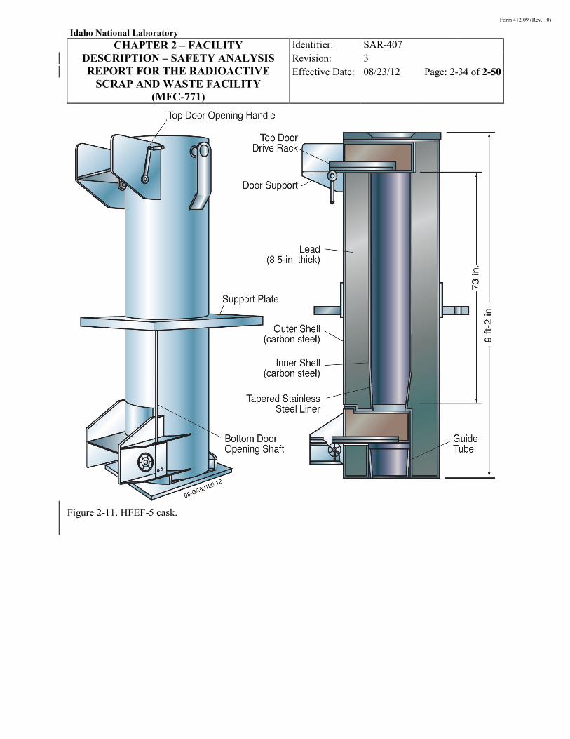
Form 412.09 (Rev. 10)
Idaho National Laboratory
CHAPTER 2 – FACILITY DESCRIPTION – SAFETY ANALYSIS REPORT FOR THE RADIOACTIVE
SCRAP AND WASTE FACILITY (MFC-771)
Identifier: Revision: Effective Date:
SAR-407 3 08/23/12 Page: 2-34 of 2-50
Figure 2-11. HFEF-5 cask.

Form 412.09 (Rev. 10)
Idaho National Laboratory
CHAPTER 2 – FACILITY DESCRIPTION – SAFETY ANALYSIS REPORT FOR THE RADIOACTIVE
SCRAP AND WASTE FACILITY (MFC-771)
Identifier: Revision: Effective Date:
SAR-407 3 08/23/12 Page: 2-35 of 2-50
Figure 2-12. HFEF-14 cask.

Form 412.09 (Rev. 10)
Idaho National Laboratory
CHAPTER 2 – FACILITY DESCRIPTION – SAFETY ANALYSIS REPORT FOR THE RADIOACTIVE
SCRAP AND WASTE FACILITY (MFC-771)
Identifier: Revision: Effective Date:
SAR-407 3 08/23/12 Page: 2-36 of 2-50
2.5.2.9 Interim Storage Container. The ISCs provide shielding for operations in support of retrieval and for transport of the 16-in. HFEF-5 cans from RSWF to other INL facilities. They are not safety-significant SSC containers like the HFEF-5 and -14 casks. The ISCs are vented, reinforced-concrete boxes with space for four HFEF-5 cans or HFEF-type containers placed vertically in the center of the box. The dimensions, with lid in place, are 80 × 80 × 99 in. The bottom and top both have a thickness of 9 in. of concrete, and the sides have a thickness of 24 in. of concrete. Each wall has a vent (1/2-in. tubing) that penetrates the wall with a bug screen covering the outer opening. The vertical storage locations or silos are four 16-in.-diameter steel pipes with 1/4-in.-thick walls sitting on a 1/4-in. steel base plate and surrounded by concrete. The ISC with an inside clearance height of 82 in. and storage diameter of 16 in. is more than adequate to accommodate the HFEF-5 containers that measure 73.5 in. long and 12.75 in. OD (see Dwg. No. 735332 [W0147-0033-DD]26
Figure 2-13). The ISC fully loaded with four
HFEF-5 containers weighs up to 54,000 lb. A side view of the ISC is presented in , and a top view showing the four storage locations is presented in Figure 2-14.27,28
The ISC can be moved inside RSWF and inside the RSWF Staging Area without the lid if the ISC is secured to the trailer. (Note: This exception is being included to reduce the number of times the ISC lid is secured to the ISC and, therefore, the number of times personnel need to set up the crane and work on the elevated surfaces [safety issue] to secure the ISC lid.)
The TRU-ISCs are vented, reinforced-concrete boxes with space for four 55- or 30-gallon Type A drums placed vertically in the center of the box. The dimensions, with lid in place, are 80 × 80 × 45 in. The bottom and top both have a thickness of 9 in. of concrete, and the sides have a thickness of 10 in. of concrete. Each wall has a vent (1/2-in. tubing) that penetrates the wall with a bug screen covering the outer opening. The vertical storage locations or silos are four 16-in.-diameter steel pipes with 1/4-in.-thick walls sitting on a 1/4-in. steel base plate and surrounded by concrete. The TRU-ISC with an inside clearance height of 43 in. and storage diameter of 16 in. is more than adequate to accommodate the Department of Transporation (DOT) Type A 55-gal containers that measure 33 in. long and 22.5 in. OD. The TRU-ISC fully loaded with four Type A containers weighs up to 27,100 lb. A top view of the TRU-ISC showing room for four storage locations is presented in Figure 2-15.
2.5.2.10 Facility Transfer Container. The FTC provides shielding for operations in support of retrieval and for transport of 24-in. large liners (LLs) loaded with original 16-in. liners and SLSF containers stored in 26-in. liners from RSWF to other INL facilities. An FTC is not a safety-significant SSC container like the HFEF-5 and -14 casks. The FTC is approximately 42 in. in diameter and 15 ft 3.5 in. long and weighs approximately 30,000 lb. Figure 2-16 is a graphic depiction of the FTC.
The FTC is comprised of two major components. The outer component is welded, stainless steel construction providing strength and structure to lift and transport a payload. The inner component is also welded, stainless steel construction to support the loaded liner during transport and to allow for decontamination, if necessary.

Form 412.09 (Rev. 10)
Idaho National Laboratory
CHAPTER 2 – FACILITY DESCRIPTION – SAFETY ANALYSIS REPORT FOR THE RADIOACTIVE
SCRAP AND WASTE FACILITY (MFC-771)
Identifier: Revision: Effective Date:
SAR-407 3 08/23/12 Page: 2-37 of 2-50
Figure 2-13. Side view of ISC.

Form 412.09 (Rev. 10)
Idaho National Laboratory
CHAPTER 2 – FACILITY DESCRIPTION – SAFETY ANALYSIS REPORT FOR THE RADIOACTIVE
SCRAP AND WASTE FACILITY (MFC-771)
Identifier: Revision: Effective Date:
SAR-407 3 08/23/12 Page: 2-38 of 2-50
Figure 2-14. Top view of the ISC.

Form 412.09 (Rev. 10)
Idaho National Laboratory
CHAPTER 2 – FACILITY DESCRIPTION – SAFETY ANALYSIS REPORT FOR THE RADIOACTIVE
SCRAP AND WASTE FACILITY (MFC-771)
Identifier: Revision: Effective Date:
SAR-407 3 08/23/12 Page: 2-39 of 2-50
Figure 2-15. A top view of TRU-ISC.

Form 412.09 (Rev. 10)
Idaho National Laboratory
CHAPTER 2 – FACILITY DESCRIPTION – SAFETY ANALYSIS REPORT FOR THE RADIOACTIVE
SCRAP AND WASTE FACILITY (MFC-771)
Identifier: Revision: Effective Date:
SAR-407 3 08/23/12 Page: 2-40 of 2-50
Figure 2-16. Facility transfer container.
The FTC requires the use of related equipment. Each item is locally manufactured, welded stainless steel construction including:
• FTC shipping skid
• FTC lift yoke
• FTC funnel
• FTC lift assist skid
• FTC receiving station.
Other lifting, hoisting, and rigging equipment, as identified in Section 2.5.2, may be used with the FTC and related equipment. All equipment, including lifting, hoisting, and rigging equipment, must be in compliance with the INL hoisting and rigging program.
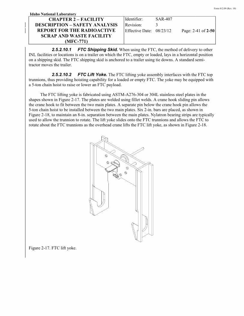
Form 412.09 (Rev. 10)
Idaho National Laboratory
CHAPTER 2 – FACILITY DESCRIPTION – SAFETY ANALYSIS REPORT FOR THE RADIOACTIVE
SCRAP AND WASTE FACILITY (MFC-771)
Identifier: Revision: Effective Date:
SAR-407 3 08/23/12 Page: 2-41 of 2-50
2.5.2.10.1 FTC Shipping Skid. When using the FTC, the method of delivery to other INL facilities or locations is on a trailer on which the FTC, empty or loaded, lays in a horizontal position on a shipping skid. The FTC shipping skid is anchored to a trailer using tie downs. A standard semi-tractor moves the trailer.
2.5.2.10.2 FTC Lift Yoke. The FTC lifting yoke assembly interfaces with the FTC top trunnions, thus providing hoisting capability for a loaded or empty FTC. The yoke may be equipped with a 5-ton chain hoist to raise or lower an FTC payload.
The FTC lifting yoke is fabricated using ASTM-A276-304 or 304L stainless steel plates in the shapes shown in Figure 2-17. The plates are welded using fillet welds. A crane hook sliding pin allows the crane hook to fit between the two main plates. A separate pin below the crane hook pin allows the 5-ton chain hoist to be installed between the two main plates. Six 2-in. bars are placed, as shown in Figure 2-18, to maintain an 8-in. separation between the main plates. Nylatron bearing strips are typically used to allow the trunnion to rotate. The lift yoke slides onto the FTC trunnions and allows the FTC to rotate about the FTC trunnions as the overhead crane lifts the FTC lift yoke, as shown in Figure 2-18.
Figure 2-17. FTC lift yoke.

Form 412.09 (Rev. 10)
Idaho National Laboratory
CHAPTER 2 – FACILITY DESCRIPTION – SAFETY ANALYSIS REPORT FOR THE RADIOACTIVE
SCRAP AND WASTE FACILITY (MFC-771)
Identifier: Revision: Effective Date:
SAR-407 3 08/23/12 Page: 2-42 of 2-50
Figure 2-18. FTC lift yoke translating vertical to horizontal.
2.5.2.10.3 FTC Funnel. The FTC funnel is an assembly which is seated on top of the open FTC during top-loading operations. As with the other FTC equipment, the FTC funnel is fabricated using ASTM-A276-304 or -304L stainless steel.
2.5.2.10.4 FTC Lift Assist Skid. The FTC lift assist skid (LAS) is a trailer-mounted structure that allows the FTC to be transported over the road within the INL. The LAS integrates with the lower FTC trunnions and controls the lateral movement of the lower end of the FTC as it translates between the vertical and horizontal positions. The LAS itself may be skid-mounted on any commercial flat bed trailer meeting load capacity and size, provided the trailer meets all DOT and INL transportation requirements. The FTC LAS is fabricated using ASTM-A276-304 or -304L stainless steel, as shown in Figure 2-19.
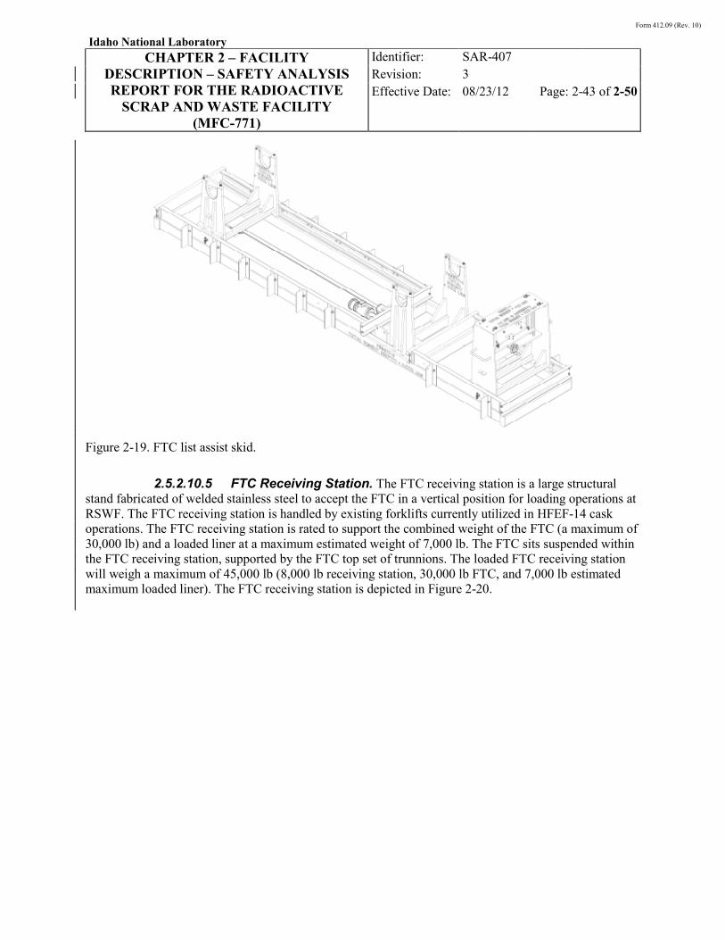
Form 412.09 (Rev. 10)
Idaho National Laboratory
CHAPTER 2 – FACILITY DESCRIPTION – SAFETY ANALYSIS REPORT FOR THE RADIOACTIVE
SCRAP AND WASTE FACILITY (MFC-771)
Identifier: Revision: Effective Date:
SAR-407 3 08/23/12 Page: 2-43 of 2-50
Figure 2-19. FTC list assist skid.
2.5.2.10.5 FTC Receiving Station. The FTC receiving station is a large structural stand fabricated of welded stainless steel to accept the FTC in a vertical position for loading operations at RSWF. The FTC receiving station is handled by existing forklifts currently utilized in HFEF-14 cask operations. The FTC receiving station is rated to support the combined weight of the FTC (a maximum of 30,000 lb) and a loaded liner at a maximum estimated weight of 7,000 lb. The FTC sits suspended within the FTC receiving station, supported by the FTC top set of trunnions. The loaded FTC receiving station will weigh a maximum of 45,000 lb (8,000 lb receiving station, 30,000 lb FTC, and 7,000 lb estimated maximum loaded liner). The FTC receiving station is depicted in Figure 2-20.
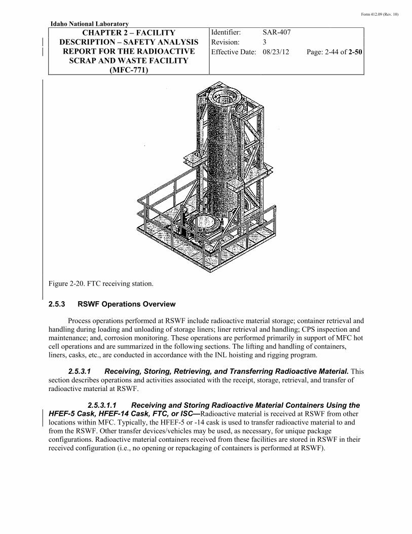
Form 412.09 (Rev. 10)
Idaho National Laboratory
CHAPTER 2 – FACILITY DESCRIPTION – SAFETY ANALYSIS REPORT FOR THE RADIOACTIVE
SCRAP AND WASTE FACILITY (MFC-771)
Identifier: Revision: Effective Date:
SAR-407 3 08/23/12 Page: 2-44 of 2-50
Figure 2-20. FTC receiving station.
2.5.3 RSWF Operations Overview
Process operations performed at RSWF include radioactive material storage; container retrieval and handling during loading and unloading of storage liners; liner retrieval and handling; CPS inspection and maintenance; and, corrosion monitoring. These operations are performed primarily in support of MFC hot cell operations and are summarized in the following sections. The lifting and handling of containers, liners, casks, etc., are conducted in accordance with the INL hoisting and rigging program.
2.5.3.1 Receiving, Storing, Retrieving, and Transferring Radioactive Material. This section describes operations and activities associated with the receipt, storage, retrieval, and transfer of radioactive material at RSWF.
2.5.3.1.1 Receiving and Storing Radioactive Material Containers Using the HFEF-5 Cask, HFEF-14 Cask, FTC, or ISC—Radioactive material is received at RSWF from other locations within MFC. Typically, the HFEF-5 or -14 cask is used to transfer radioactive material to and from the RSWF. Other transfer devices/vehicles may be used, as necessary, for unique package configurations. Radioactive material containers received from these facilities are stored in RSWF in their received configuration (i.e., no opening or repackaging of containers is performed at RSWF).
Form 412.09 (Rev. 10)
Idaho National Laboratory
CHAPTER 2 – FACILITY DESCRIPTION – SAFETY ANALYSIS REPORT FOR THE RADIOACTIVE
SCRAP AND WASTE FACILITY (MFC-771)
Identifier: Revision: Effective Date:
SAR-407 3 08/23/12 Page: 2-45 of 2-50
The options for transferring containers from the HFEF-5cask and HFEF-14 cask in RSWF include placement over storage liners or open air transfers between the cask and an ISC or FTC. A cask positioning device is placed on the liner to facilitate the smooth transfer of a radioactive material container from the cask into the liner. Although the positioning device provides some shielding from the direct radiation hazard that exists during the transfer, supplemental temporary shielding may also be used, as necessary, to minimize direct radiation exposure.
The loaded cask is transferred to the designated liner using a forklift, and seated on the positioning ring. Once the cask is properly seated, the top shield door/plate of the cask is opened/removed, hoisting and rigging tackle is connected to the loaded container, the bottom shield door of the cask is opened, and the container is lowered into the liner using a mobile crane. When the transfer has been completed, the forklift and positioning device are moved, and the liner is closed. When the concrete shield plug is used for closure, the retrieval cable attached to the top of the container is connected to the bottom of the shield plug/cover plate for ease of future container retrieval. Visual and/or non-destructive examination of closure cover welds is performed, as necessary, in accordance with applicable procedures.
With the open-air transfer option, the forklift and cask are positioned adjacent to the designated liner. The top shield door/plate of the cask is opened/removed, hoisting and rigging tackle is connected to the loaded container, and mobile lifting and handling equipment is used to lift the container from the cask, swing it through the air unshielded, and place it into the liner. When the shield plug/cover plate is used for closure, the retrieval cable can be attached from the top of the container to the bottom of the shield plug/cover plate for ease of future container retrieval. Visual and/or non-destructive examination of closure cover welds is performed, as necessary, in accordance with applicable procedures.
2.5.3.1.2 Retrieving and Transferring Containers Using the HFEF-5 and HFEF-14 Casks—Prior to cutting/opening a liner to remove a container, vent/purge taps are drilled into the liner wall. The liner is then purged with an inert gas or passively vented to ensure the absence of potential flammable gas mixtures prior to cutting (liner purging/venting is only performed on liners with welded closure covers). Sampling of the liner atmosphere is performed to confirm the absence of a flammable gas mixture when a liner is passively vented. The liner cover/shield plug is removed in accordance with applicable operating procedures. For a welded lid, this process includes welding a lifting lug to the liner lid (if necessary), removing the weld on the shield plug with a cutting torch, and removal of the shield plug using a crane.
Similar to the liner loading evolution, there are two options for retrieving containers from liners using the HFEF-5 and HFEF-14 casks: the bottom load method and the open-air transfer method. For the bottom load method, a positioning device is used to facilitate the smooth transfer of the container from the liner into the transfer cask (supplemental temporary shielding may also be used, as necessary, to minimize direct radiation exposure). The container is raised into the cask using a mobile crane and approved hoisting and rigging tackle. Once the container is inside the cask, the cask doors are closed and the transfer proceeds. With the open-air transfer method, the forklift and cask are positioned adjacent to the designated liner, and the top shield door/plate of the cask is opened/removed. Once the liner is opened as described above, hoisting and rigging tackle is connected to the waste container, and mobile lifting and handling equipment is used to lift the container from the liner, swing it through the air unshielded, and load it into the cask. Once loaded, the hoisting and rigging tackle is disconnected, the top shield door/plate is closed/installed, and the loaded cask is ready for transfer.
Form 412.09 (Rev. 10)
Idaho National Laboratory
CHAPTER 2 – FACILITY DESCRIPTION – SAFETY ANALYSIS REPORT FOR THE RADIOACTIVE
SCRAP AND WASTE FACILITY (MFC-771)
Identifier: Revision: Effective Date:
SAR-407 3 08/23/12 Page: 2-46 of 2-50
2.5.3.1.3 Retrieving and Transferring Containers Using the ISC—As an alternative to using the HFEF-5 cask or HFEF-14 cask, RSWF personnel may retrieve waste containers from an open storage liner by crane and immediately transfer the container via open-air transfer to a prepared ISC. RSWF personnel must first inspect waste container lifting cables in accordance with applicable facility procedures. If necessary, unacceptable lifting cables will be replaced prior to lifting the containers.
Loading the ISC may involve the movement of a partially loaded ISC without the lid in place to position the ISC for another loading event or to the staging area. Partially loaded ISCs can be moved via transport trailer without the lid if the ISC is secured to the trailer. When preparing a loaded ISC for transport, the lid may be placed on the ISC either within RSWF or within the RSWF Staging Area. Only one ISC is placed on a trailer at any given time. If conditions warrant, an ISC may be placed on the ground and loaded. However, a loaded or partially loaded ISC must have the lid in place when being moved with a fork-lift. When using the transport trailer, the lid of the ISC will be re-attached by appropriate INL personnel either within RSWF or within the RSWF Staging Area. Only one ISC is placed on a trailer at any given time.
2.5.3.1.4 Retrieving and Transferring Retrievable Containers and Overpacked Liners Using the FTC—There are two options for loading the FTC: bottom loading or open-air transfer. For bottom loading, the FTC and the FTC receiving station are placed on the ground using cribbing, as necessary, to ensure alignment with the waste container to be retrieved and to avoid contact with adjacent liners. The bottom plug is lowered onto a cart, which is then transferred from under the FTC bore. With the bottom plug out of the way, alignment of the FTC bore with the liner below is confirmed. A mobile crane is used to lower the hoisting and rigging equipment down through the FTC to allow connection to the liner or SLSF container.
For 24-in. liners, the rigging is attached directly to the top of the liner. The 24-in. liner is first prepped by excavating soil from around the liner using mechanical means such as a locally manufactured hollow stem auger or a regular bit and vacuum excavation truck. After soil excavation and rigging equipment attachment, the liner is lifted into the FTC. Once inside the FTC, the lower plug is placed back into position and secured. The 24-in. liner is then lowered onto the bottom plug, and the rigging is then removed. The top plug is then replaced and re-secured.
For SLSF containers or other retrievable containers that are compatible with the FTC, the operation is similar. The 26-in. liner used for storing the SLSF is opened, and the FTC receiving station is staged over the opening using cribbing, as necessary, to ensure alignment with the waste container to be retrieved and to avoid contact with adjacent liners. Similar to the 24-in. liners, the FTC bottom plug is removed, and rigging is lowered from a mobile crane down through the FTC and attached to the container. Once a retrieved container is pulled up into the FTC, the FTC bottom plug is placed back into position and re-secured. The retrieved container is then lowered onto the secured FTC bottom plug. Once the retrieved container is sitting on the plug, the rigging is removed, and the top plug replaced and re-secured.
For open-air transfer operations, the FTC and receiving station can be staged near the container location. This can be anywhere within RSWF but is typically on the asphalt road adjacent to RSWF or in the BB row inside the RSWF perimeter fence. The top plate of the FTC is removed, and a funnel is placed at the top of the FTC facilitating alignment. Using mobile lifting and handling equipment, the 24-in. liner
Form 412.09 (Rev. 10)
Idaho National Laboratory
CHAPTER 2 – FACILITY DESCRIPTION – SAFETY ANALYSIS REPORT FOR THE RADIOACTIVE
SCRAP AND WASTE FACILITY (MFC-771)
Identifier: Revision: Effective Date:
SAR-407 3 08/23/12 Page: 2-47 of 2-50
or container is retrieved from its respective storage location. The 24-in. liner or container is lifted to a safe height, aligned over the FTC funnel, and then lowered into the FTC until it rests on the FTC bottom plug. The rigging is then removed, and the top plug replaced and re-secured. The top plug and funnel removal/replacement activities can be conducted either in RSWF or in the RSWF Staging Area.
2.5.3.1.5 Retrieving and Transferring Double Cans from 16-in. Liners Overpacked in 24-in. Liners—In some storage configurations, the over-packed original 16-in. liner contains radioactive material in a double can container (e.g., HFEF-5 can). These cans may be removed and transferred to another liner to allow removal of the 16-in. liner for subsequent inspection of the inside of the 24-in. liner. Prior to opening the liners, they are purged/vented (if a welded closure cover is present) for removal of potential flammable gases (e.g., hydrogen). Once purged/vented, the 24-in. liner cover/shield assembly is removed. Purging/venting of the 16-in. liner is also completed prior to opening. The container is retrieved via open air transfer directly into an HFEF-5 cask or into an ISC.
2.5.3.1.6 Retrieving and Transferring Retrievable Non-Standard Containers—Retrieval and transfer of non-standard containers (e.g., cold trap, nuclide traps) may be performed in accordance with approved procedures. Lifting lugs welded to the non-standard containers provide for handling during removal from the liner. Handling is performed using a crane and appropriate rigging equipment in accordance with applicable hoisting and rigging requirements. Because of the unique size and configuration of non-standard packages, a tractor/trailer, or other similar vehicle, is used to move them once they are retrieved from a liner.
2.5.3.1.7 Cathodic Protection System Surveillance and Maintenance—Inspection of the CPS is required by the RSWF HWMA/RCRA permit3 and consists of weekly, monthly and annual inspections. The inspections serve to verify that the system is operating properly. Maintenance of the CPS is also performed and includes adjustments to rectifiers and periodic replacement of the anodes since they are “consumed” during the course of normal operation. Anode replacement involves operation of an industrial vacuum system, excavator, and/or auger for soil removal, placement of new anodes, and making appropriate connections to the liner and CPS. Post-installation testing is performed as necessary. The surveillance and maintenance activities associated with the RSWF CPS are described in detail in Reference 7.
2.5.3.1.8 Corrosion Monitoring—Corrosion monitoring provides verification and assurance that the CPS is adequately protecting the storage liners. Corrosion monitoring is required by the RSWF HWMA/RCRA permit3 and consists primarily of the removal and examination of one corrosion surveillance liner (described in Section 2.4.1) every four years. The exhumed liner is inspected to determine the extent of corrosion. Examination of an exhumed liner includes visual examination and measurement of its wall thickness. The data resulting from the inspection and examination provides verification and assurance of the effectiveness of the cathodic protection. The inspections are performed and/or supervised by an independent corrosion engineer and documented as part of the facility operating records.
2.5.3.1.9 Miscellaneous Operations—Miscellaneous operations and activities at RSWF include installation of new storage liners, including hole boring and lifting/handling of empty liners for placement in holes; facility maintenance and surveillance activities (e.g., vegetation removal, soil cover maintenance, etc.); and, temporary staging of a loaded, closed cask within the facility.
Form 412.09 (Rev. 10)
Idaho National Laboratory
CHAPTER 2 – FACILITY DESCRIPTION – SAFETY ANALYSIS REPORT FOR THE RADIOACTIVE
SCRAP AND WASTE FACILITY (MFC-771)
Identifier: Revision: Effective Date:
SAR-407 3 08/23/12 Page: 2-48 of 2-50
2.6 Confinement Systems Since 1978, the operating approach at RSWF is to provide at least two barriers to limit potential
releases of radioactive material to the environment. The RSWF includes the following features for confinement of the radioactive material stored at the facility:
• Radioactive material containers 2.4.2. As described in Section , the RSWF liners store radioactive material that was packaged in various containers and configurations. The type of container used depends on when it was loaded. The inner/outer can configuration (e.g., HFEF-5 container, SLSF, and RH-TRU cans) used since 1978 provides two levels of confinement for the radioactive material stored inside. Non-standard packages (cold trap, nuclide traps) were also configured to provide double confinement of the radioactive material stored. Fuel cladding may also provide an added layer of confinement within a container, depending on its condition.
• RSWF storage liners
•
. The carbon steel liners provide the final confinement barrier between the stored radioactive material and the environment.
HFEF-5 and -14 casks
•
. While the casks principally provide shielding from the direct radiation hazard and physical (structural) protection of containers, they may also provide confinement of radioactive material during transfer within RSWF.
Lag storage liners
2.7 Safety Support Systems
. 30-in. carbon steel liners available for temporary storage of excavated LLs.
There are no safety support systems (e.g., fire protection system, criticality monitoring, radiological monitoring) at the RSWF.
2.8 Utility Distribution Systems
RSWF is supplied with 480-volt, three-phase electric power received from a post across from SCMS (MFC-793). The power is used primarily for the CPS, lighting and heating for the personnel office trailer, portable electrical equipment, and security systems. RSWF has no water, sewer or telephone utilities.
2.9 Auxiliary Systems and Support Facilities
2.9.1 Personnel Access Trailer
A personnel office trailer (TR-64), 14 ft wide by 66 ft long, is located outside the west side of RSWF; however, the trailer dimensions may change resulting from periodic equipment upgrades. The trailer provides personnel work space during normal operations, and personnel access to the RSWF. The trailer contains standard electrical lighting and outlets and telephone service.
Form 412.09 (Rev. 10)
Idaho National Laboratory
CHAPTER 2 – FACILITY DESCRIPTION – SAFETY ANALYSIS REPORT FOR THE RADIOACTIVE
SCRAP AND WASTE FACILITY (MFC-771)
Identifier: Revision: Effective Date:
SAR-407 3 08/23/12 Page: 2-49 of 2-50
2.9.2 Security System
The safeguard security system at RSWF includes the physical and ACs necessary to prevent unauthorized access to the facility and diversion of special nuclear material. Security features for RSWF are explained in the facility safeguards and security plan.
2.10 References
1. PLN-1851, “Transport Plan for the Transfer of Waste Containers between RWMC and INTEC, and RSWF and INTEC,” Idaho Cleanup Project, Rev. 4, November 2009.
2. DOE O 420.1B, Change 1, “Facility Safety,” U.S. Department of Energy, April 2010.
3. PER-116, “HWMA RCRA Partial Permit, Materials and Fuels Complex,” EPA ID No. 4890008952, current revision.
4. ECAR-1084, “RSWF Staging Area Roadway and Buried Pipe Evaluation,” Rev. 0, July 2010.
5. SAR-413, “Safety Analysis Report for Inter-Facility Transfers at MFC,” current revision.
6. LST-337, “Approved Container/Payload List for Inter-Facility Transfer Operations at MFC,” current revision.
7. SDD-225, “Radioactive Scrap and Waste Facility Storage Liner System,” current revision.
8. Jeremy A. Hailey, Northwest Corrosion Engineering, letter to Thomas Hipp, BEA, “Independent Corrosion Assessment of the Internal Surfaces of 24 Inch Liners,” CCN 221679, June 30, 2010.
9. ECAR-1932, “RSWF Liner Base Strength Verification,” Rev. 0. May 2012.
10. INL/INT-08-14180, “Criticality Safety Evaluation for the Radioactive Scrap and Waste Facility (MFC-771),” Rev. 0, July 2008.
11. W. F. Holcomb, D. M. Paige, C. E. Stevenson, E. D. Graham, “High Level Radioactive Solid Waste Burial Operations for the EBR-II Fuel Cycle Facility,” Nuclear Engineering and Design, 5, pgs. 221-227, 1967.
12. C. E. Stevenson, “The EBR-II Fuel Cycle Story,” American Nuclear Society, 1987 [available in the INL Technical Library].
13. EDF-7658, “MFC Inter-Facility Transfer of Radioactive Materials in the HFEF-5 Cask,” Rev. 3, April 2009.
14. EDF-7659, “MFC Inter-Facility Transfer of Radioactive Materials in the HFEF-14 Cask,” Rev. 6, October 2009.
15. NACE Recommended Practice, RP-0285, “Recommended Practice – Corrosion Control of Underground Storage Tank Systems by Cathodic Protection,” current revision.

Form 412.09 (Rev. 10)
Idaho National Laboratory
CHAPTER 2 – FACILITY DESCRIPTION – SAFETY ANALYSIS REPORT FOR THE RADIOACTIVE
SCRAP AND WASTE FACILITY (MFC-771)
Identifier: Revision: Effective Date:
SAR-407 3 08/23/12 Page: 2-50 of 2-50
16. SAR-400, “INL Standardized Safety Analysis Report,” current revision.
17. ECAR-309, “RSWF Storage Liners Structural Evaluation,” Rev. 1, April 2012.
18. ECAR-1827, “RSWF Equipment Loading Adjacent to Liners,” Rev. 1, June 2012.
19. ECAR-1213, “RSWF Hoisting and Rigging Plans,” Rev. 5, June 2012.
20. F3003-0031-AK, “EBR-II Fuel Storage at RSWF,” Rev. 3, December 1999.
21. EDF-7224, “Criticality Safety Evaluation for MFC Inter-Facility Transfers of Spent Nuclear Fuel Using the HFEF-5 Cask,” Rev. 0, August 2006.
22. W7000-0161-ES, “A Report on EBR-II Special Components Considered as Candidates for Treatment Using the MEDE Process,” Rev. 0, September 2006.
23. DOE-STD-1090-2011, “Hoisting and Rigging Standard,” U.S. Department of Energy, September 2011.
24. SDD-201, “HFEF-5 Waste Cask,” current revision.
25. SDD-202, “HFEF-14 Waste Cask,” current revision.
26. Dwg. No. 735332 (W0147-0033-DD), “HFEF/N Waste Can Assembly,” Rev. 16, June 2010.
27. TBL-300, “Shielding Calculations for the Facility Transfer Container (FTC),” Idaho Cleanup Project, Rev. 0, September 2010.
28. EDF-8702, “Design Modifications for the Interim Storage Containers Used to Transport HFEF-5 Waste Canisters,” Idaho Cleanup Project, Rev. 1, April 2009.

Form 412.09 (Rev. 10)
Idaho National Laboratory
CHAPTER 3 – HAZARD AND ACCIDENT ANALYSES – SAFETY ANALYSIS
REPORT FOR THE RADIOACTIVE SCRAP AND WASTE FACILITY
(MFC-771)
Identifier: Revision: Effective Date:
SAR-407 3 08/23/12 Page: 3-1 of 3-92
CHAPTER 3
HAZARD AND ACCIDENT ANALYSES

Form 412.09 (Rev. 10)
Idaho National Laboratory
CHAPTER 3 – HAZARD AND ACCIDENT ANALYSES – SAFETY ANALYSIS
REPORT FOR THE RADIOACTIVE SCRAP AND WASTE FACILITY
(MFC-771)
Identifier: Revision: Effective Date:
SAR-407 3 08/23/12 Page: 3-2 of 3-92
CONTENTS
3. HAZARD AND ACCIDENT ANALYSES .................................................................................... 3-3
3.1 Introduction ........................................................................................................................ 3-3
3.2 Requirements ...................................................................................................................... 3-3
3.3 Hazard Analysis.................................................................................................................. 3-4
3.3.1 Methodology ................................................................................................... 3-4 3.3.2 Hazard Analysis Results ............................................................................... 3-15
3.4 Accident Analysis ............................................................................................................. 3-75
3.4.1 Methodology ................................................................................................. 3-75 3.4.2 Design Basis Accidents................................................................................. 3-77 3.4.3 Beyond Design Basis Accidents ................................................................... 3-87
3.5 References ........................................................................................................................ 3-87
FIGURES
Figure 3-1. Qualitative risk matrix for the off-site public. ....................................................................... 3-12 Figure 3-2. Qualitative risk matrix for on-site collocated workers. ......................................................... 3-13 Figure 3-3. Qualitative risk matrix for facility workers. .......................................................................... 3-14 Figure 3-4. Fire triangle. .......................................................................................................................... 3-36
TABLES
Table 3-1. Representative sampling from the Lessons Learned and ORPS database. ............................... 3-5 Table 3-2. Qualitative likelihood category. ............................................................................................... 3-8 Table 3-3. Qualitative consequence category for potential environmental effects. ................................... 3-8 Table 3-4. Qualitative consequence category. ........................................................................................... 3-9 Table 3-5. INL risk evaluation guidelines. .............................................................................................. 3-10 Table 3-6. Summary of non-routine material and energy hazard sources. .............................................. 3-15 Table 3-7. Examples of fissionable materials stored at RSWF. ............................................................... 3-17 Table 3-8. Standard industrial hazards regulated by DOE-prescribed OSH standards. ........................... 3-21 Table 3-9. Summary of RSWF hazard evaluation results. ....................................................................... 3-24 Table 3-10. Assumed material at risk for container drop accident analysis (base case). ........................ 3-78 Table 3-11. Container drop release accident consequences. .................................................................... 3-79 Table 3-12. Assumed material-at-risk for hydrogen explosion/sodium fire. ........................................... 3-81 Table 3-13. Hydrogen explosion/sodium fire release consequences. ...................................................... 3-82 Table 3-14. Assumed material-at-risk for vehicle fuel fire. ..................................................................... 3-83 Table 3-15. Vehicle fuel fire release consequences. ................................................................................ 3-84 Table 3-16. Criticality accident direct radiation dose consequences. ...................................................... 3-86

Form 412.09 (Rev. 10)
Idaho National Laboratory
CHAPTER 3 – HAZARD AND ACCIDENT ANALYSES – SAFETY ANALYSIS
REPORT FOR THE RADIOACTIVE SCRAP AND WASTE FACILITY
(MFC-771)
Identifier: Revision: Effective Date:
SAR-407 3 08/23/12 Page: 3-3 of 3-92
3. HAZARD AND ACCIDENT ANALYSES
3.1 Introduction
This chapter identifies and evaluates potential hazards associated with RSWF and its associated operations as described in Chapter 2. The hazard category for the facility is stated. In addition, this chapter contains the quantitative consequence analyses of postulated representative, bounding, and unique accidents selected from the hazard analysis. Accidents beyond the design basis are also discussed.
3.2 Requirements
10 CFR Part 830, Subpart B, “Safety Basis Requirements,”1 DOE-STD-1027-92, “Hazard Categorization and Accident Analysis Techniques for Compliance with DOE Order 5480.23, Nuclear Safety Analysis Reports,”2 and DOE-STD-3009-94, “Preparation Guide for U.S. Department of Energy Nonreactor Nuclear Facility Documented Safety Analyses,”3 establish requirements and guidelines for performing hazard and accident analyses and provide a methodology for hazard categorization. Preparation of this safety analysis is in accordance with 10 CFR 830, Subpart B and DOE-STD-3009-94. Additional guidance relevant to the development of the safety analysis is provided in DOE G 421.1-2, “Implementation Guide for Use in Developing Documented Safety Analyses to Meet Subpart B of 10 CFR 830.”4 In addition, the principles and requirements of process safety management in 29 CFR 1910.119, “Process Safety Management of Highly Hazardous Chemicals,”5
Guidance applicable to the development of controls, specifically the TSRs, is provided in DOE G 423.1-1, “Implementation Guide for Use in Developing Technical Safety Requirements,”
apply to nuclear facilities with hazardous chemical inventories at or above the threshold quantity (TQ) established in 29 CFR 1910.119.
6 and in DOE-STD-1186-2004, “Specific Administrative Controls.”7
DOE-ID, in conjunction with the INL management and operating contractor, has established evaluation guidelines for the consistent development of safety analyses for nuclear facilities at the INL. These evaluation guidelines include Risk Evaluation Guidelines and criteria for the selection of safety-class and safety-significant SSCs and TSRs.
This standard provides guidance applicable to those ACs designated as SACs, which are selected to provide preventive and/or mitigative functions for specific HEs. These SACs have safety importance equivalent to engineered controls that would be classified as safety-class or safety-significant if the engineered controls were available and selected.
8

Form 412.09 (Rev. 10)
Idaho National Laboratory
CHAPTER 3 – HAZARD AND ACCIDENT ANALYSES – SAFETY ANALYSIS
REPORT FOR THE RADIOACTIVE SCRAP AND WASTE FACILITY
(MFC-771)
Identifier: Revision: Effective Date:
SAR-407 3 08/23/12 Page: 3-4 of 3-92
DOE-STD-5506-2007, “Preparation of Safety Basis Documents for Transuranic (TRU) Waste Facilities,” 9
3.3 Hazard Analysis
provides guidance and requirements for hazard identification and analysis, accident analysis and evaluation guidelines, and control selection specific to TRU waste activities at DOE facilities. The radioactive materials stored at RSWF include TRU waste, SNF and associated accountable material, and LLW. Operations and activities at RSWF are established based on the remote-handled nature (i.e., high radiation level) of the materials stored and handled at the facility and the specific container/package being stored/handled, and are not unique to the type of material being handled (i.e., SNF, TRU, LLW). In addition, there are minor differences between the requirements of DOE-STD-5506 and other approved methodologies used at INL (e.g., risk consequence binning). The guidance and requirements prescribed in DOE-STD-5506 were reviewed, and incorporated as appropriate, during development of this chapter. When the guidance or requirements of DOE-STD-5506 were not considered appropriate or applicable to RSWF, such departure is described in the pertinent sections of this chapter.
The hazard analysis methodology and the results of the hazard analysis of RSWF and associated operations, as described in Chapter 2, are presented in this section.
3.3.1 Methodology
The methodology used to identify and evaluate potential hazards to the public, collocated workers, facility workers, and environment from RSWF and its associated operations is summarized in the following sections.
3.3.1.1 Hazard Identification. A hazard is defined in DOE-STD-3009-94 as “a source of danger (i.e., material, energy source, or operation) with the potential to cause illness, injury, or death to personnel or damage to an operation or to the environment (without regard to the likelihood or credibility of accident scenarios or consequence mitigation).” To identify facility hazards, the following were determined:
• The material-at-risk (MAR) quantity, form, and location of radioactive and hazardous material that is available for potential release from RSWF
• Potential energy sources and initiating events that could directly result in injury to workers or lead to the release of radioactive or hazardous materials.
To ensure that potential facility hazards due to both material and energy sources were comprehensively identified, a team of experienced safety analysts and operations personnel met to review and generate initial scoping of the hazard evaluation, the standard industrial hazards, and the non-routine hazards table. Facility and material inventory information was obtained from knowledgeable operations and nuclear safety personnel, and existing facility safety and environmental documentation. The hazards identification checklist provided in NS-18104, “INL Guide to Safety Analysis Methodology”10 (Table 3-1, therein), was used to ensure that potential and relevant hazards on the checklist had been considered.

Form 412.09 (Rev. 10)
Idaho National Laboratory
CHAPTER 3 – HAZARD AND ACCIDENT ANALYSES – SAFETY ANALYSIS
REPORT FOR THE RADIOACTIVE SCRAP AND WASTE FACILITY
(MFC-771)
Identifier: Revision: Effective Date:
SAR-407 3 08/23/12 Page: 3-5 of 3-92
Relevant historical information shown in Table 3-1 was obtained from the DOE Occurrence Reporting and Processing System (ORPS). Although Table 3-1 does not list all applicable occurrences, it does provide a representative sampling of occurrences to provide insight into the spectrum of hazards potentially applicable to RSWF. Events included in the sample are the presence of hydrogen in underground storage vaults, unapproved transfers, opening a wrong liner, container drops, handling errors, and excavation errors.
Table 3-1. Representative sampling from the Lessons Learned and ORPS database. ORPS Number Event Description
EM-RL-PHMC-2006-0002 Supporting documentation for facility safety bases did not address fission product inventory (i.e., only TRU constituents) for its contribution to hydrogen generation, which caused an underestimation of hydrogen generation.
NE-ID-BEA-RTC-2006-0003 Excavation was performed near buried electrical wires without having fully verified that the wires were de-energized.
ID-BEA-TSD-2005-0001 Inter-facility transfer of spent fuel in a package not identified on the approved package/container list.
CH-AA-ANLW-TREAT-2004-0001 A transport container holding an experimental fuel element containing 50 grams of SNM was dropped approximately 24 in.
EM-ID-BBWI-2004-0003 During ILTSF vault sampling for evaluation of vault atmosphere a 100% lower flammability limit was discovered in four vaults.
EM-ID-BBWI-RWMC-2004-0006 During RH-TRU drum retrieval activities, the headspace hydrogen concentration in a storage vault was found to be above 50% of the lower flammability limit for hydrogen, calling into question the effectiveness of the vault vent/filter in preventing accumulation of hydrogen in the vault.
NE-CH-AA-ANLW-MFC-2002-0003 Efforts to retrieve spent fuel from an RSWF liner for transfer to another MFC facility resulted in a welder opening the wrong liner, which contained waste rather than spent fuel, and which had not been sampled for hydrogen/fission product gasses.
EM-ID-BBWI-FUELRCSTR-2001-0004 Sampling of underground storage vault atmosphere for gas temperature, relative humidity, and dew point was not performed as required.
NE-CH-AA-ANLW-MFC-2001-0005 Three potential inadequacies associated with the RSWF DSA were 1) impact of increasing drop height of a container into a liner above that previously analyzed, 2) thermal analysis of a liner of shorter length than previously analyzed, and 3) sampling for hydrogen gas.
EM-ID-BBWI-FUELRCSTR-2000-0006 Two underground storage wells used to store spent nuclear fuel were not purged before removing their lids. Purging of the wells is required because of the possibility of hydrogen accumulation in the dry wells.
DP-ORO-LMES-Y12NUCLEAR-1999-0071 An explosion involving a shock-sensitive material generated from the reaction of sodium-potassium (NaK) alloy and mineral oil occurred during NaK clean-up operations. The shock-sensitive material exploded when impacted by a metal tool used during the cleanup operation, resulting in a multiple-injury accident.
EM-ID-LITC-FUELRCSTR-1999-0009 Lifting equipment installed to support transfer of spent fuel from a dry storage well was found to not be supporting the element, which could lead to a drop and subsequent breach of the fuel. The transfer was being performed because older storage wells had problems with water intrusion and corrosion of the wells and fuel handling baskets.
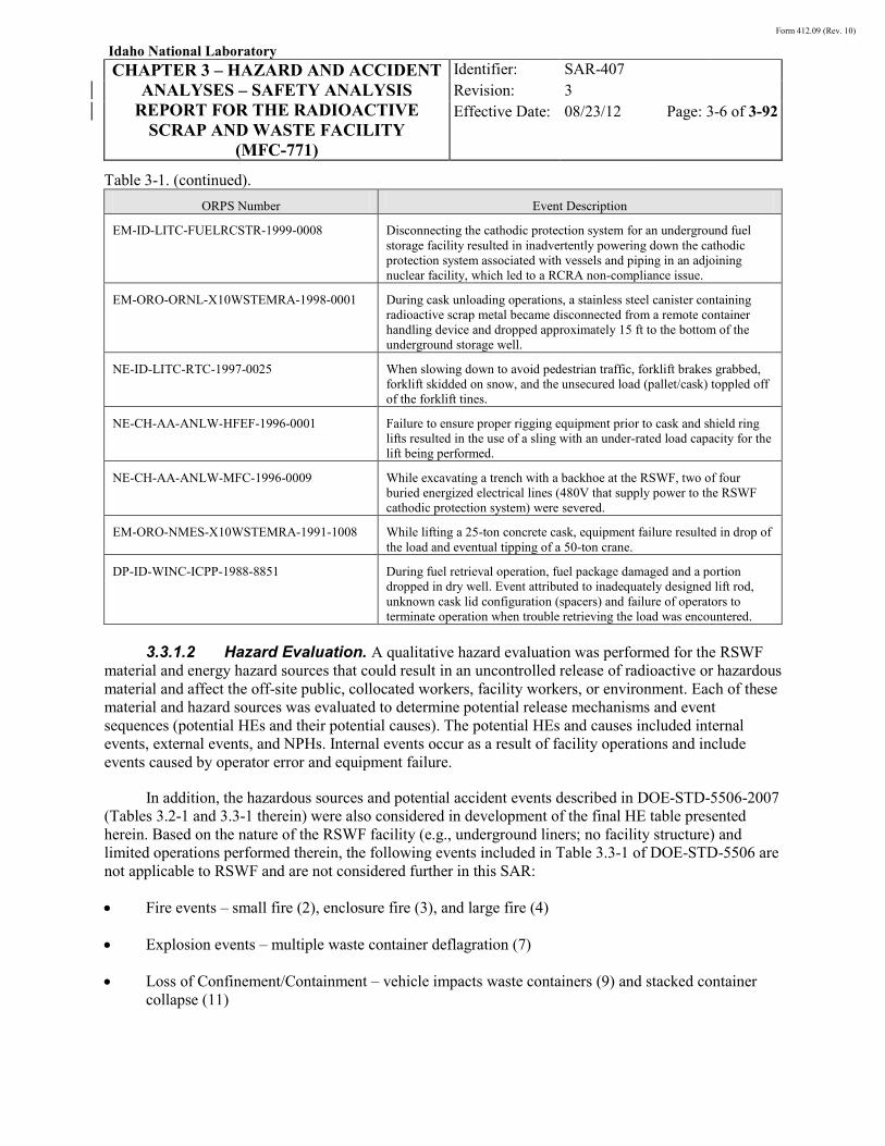
Form 412.09 (Rev. 10)
Idaho National Laboratory
CHAPTER 3 – HAZARD AND ACCIDENT ANALYSES – SAFETY ANALYSIS
REPORT FOR THE RADIOACTIVE SCRAP AND WASTE FACILITY
(MFC-771)
Identifier: Revision: Effective Date:
SAR-407 3 08/23/12 Page: 3-6 of 3-92
Table 3-1. (continued).
ORPS Number Event Description
EM-ID-LITC-FUELRCSTR-1999-0008 Disconnecting the cathodic protection system for an underground fuel storage facility resulted in inadvertently powering down the cathodic protection system associated with vessels and piping in an adjoining nuclear facility, which led to a RCRA non-compliance issue.
EM-ORO-ORNL-X10WSTEMRA-1998-0001 During cask unloading operations, a stainless steel canister containing radioactive scrap metal became disconnected from a remote container handling device and dropped approximately 15 ft to the bottom of the underground storage well.
NE-ID-LITC-RTC-1997-0025 When slowing down to avoid pedestrian traffic, forklift brakes grabbed, forklift skidded on snow, and the unsecured load (pallet/cask) toppled off of the forklift tines.
NE-CH-AA-ANLW-HFEF-1996-0001 Failure to ensure proper rigging equipment prior to cask and shield ring lifts resulted in the use of a sling with an under-rated load capacity for the lift being performed.
NE-CH-AA-ANLW-MFC-1996-0009 While excavating a trench with a backhoe at the RSWF, two of four buried energized electrical lines (480V that supply power to the RSWF cathodic protection system) were severed.
EM-ORO-NMES-X10WSTEMRA-1991-1008 While lifting a 25-ton concrete cask, equipment failure resulted in drop of the load and eventual tipping of a 50-ton crane.
DP-ID-WINC-ICPP-1988-8851 During fuel retrieval operation, fuel package damaged and a portion dropped in dry well. Event attributed to inadequately designed lift rod, unknown cask lid configuration (spacers) and failure of operators to terminate operation when trouble retrieving the load was encountered.
3.3.1.2 Hazard Evaluation. A qualitative hazard evaluation was performed for the RSWF
material and energy hazard sources that could result in an uncontrolled release of radioactive or hazardous material and affect the off-site public, collocated workers, facility workers, or environment. Each of these material and hazard sources was evaluated to determine potential release mechanisms and event sequences (potential HEs and their potential causes). The potential HEs and causes included internal events, external events, and NPHs. Internal events occur as a result of facility operations and include events caused by operator error and equipment failure.
In addition, the hazardous sources and potential accident events described in DOE-STD-5506-2007 (Tables 3.2-1 and 3.3-1 therein) were also considered in development of the final HE table presented herein. Based on the nature of the RSWF facility (e.g., underground liners; no facility structure) and limited operations performed therein, the following events included in Table 3.3-1 of DOE-STD-5506 are not applicable to RSWF and are not considered further in this SAR:
• Fire events – small fire (2), enclosure fire (3), and large fire (4)
• Explosion events – multiple waste container deflagration (7)
• Loss of Confinement/Containment – vehicle impacts waste containers (9) and stacked container collapse (11)

Form 412.09 (Rev. 10)
Idaho National Laboratory
CHAPTER 3 – HAZARD AND ACCIDENT ANALYSES – SAFETY ANALYSIS
REPORT FOR THE RADIOACTIVE SCRAP AND WASTE FACILITY
(MFC-771)
Identifier: Revision: Effective Date:
SAR-407 3 08/23/12 Page: 3-7 of 3-92
• Externally Initiated Events – aircraft impact (15), external vehicle (16 and 17), and external explosion (18)
• NPH Initiated Events – seismic event with fire (25).
External events occur independent from, but have the potential to affect, facility operations. Examples of external events include range fires, fire/explosion and releases of radioactive or hazardous material at nearby facilities or operations. NPHs include events such as earthquakes, extreme winds, floods, snow, and lightning. External events and natural phenomena that could potentially initiate accidents at RSWF are identified in Chapter 1. Sabotage and terrorism were not addressed. The analysis of postulated accidents caused by sabotage and terrorism is not within the scope of this SAR. Identifying and controlling the risk of potential sabotage and terrorist threats is the responsibility of the INL security organization.
The hazard evaluation of RSWF and associated operations was performed using a methodology similar to the “What-If” technique described in the Guidelines for Hazard Evaluation Procedures, with Worked Examples.11
The hazard evaluation was performed by personnel familiar with safety analysis methodology and similar operations at other facilities. The results were a list of potential HEs including their initiator/cause(s), qualitative estimates of likelihood and consequences, preventive and mitigative design features, and administrative controls (ACs). The hazard evaluation included review of the potential HEs identified in the then-existing safety basis documentation for the RSWF. The hazard evaluation documented in this SAR evolved over a period of several months, during which time additional analyses resulted in the need to ensure the evaluation was comprehensive. The results of the updated RSWF fire hazards analysis, as documented in HAD-429, “Radioactive Scrap and Waste Facility Fire Hazards Analysis,”
This technique encourages consideration of potential accident events and process consequences. The purpose of the what-if analysis is to identify hazards, consider the general types of accidents that can occur in a process or activity, evaluate in a qualitative fashion the effects of those accidents, and determine whether the derived controls appear adequate. The what-if analysis technique is recognized by the American Institute of Chemical Engineers (AIChE).
12
The likelihood (e.g., anticipated, unlikely, extremely unlikely, or beyond extremely unlikely) of each HE without controls (i.e., unmitigated) was qualitatively estimated using the definitions in
were incorporated into the hazard evaluation, as appropriate. The hazard evaluation methodology provided a comprehensive and systematic identification and evaluation of potential HEs.
Table 3-2. No credit was taken for controls (design or administrative features) that prevent the event. The likelihood category was based on available data, operating experience, and/or engineering judgment. If there was uncertainty in the likelihood category, a higher frequency was conservatively assumed.

Form 412.09 (Rev. 10)
Idaho National Laboratory
CHAPTER 3 – HAZARD AND ACCIDENT ANALYSES – SAFETY ANALYSIS
REPORT FOR THE RADIOACTIVE SCRAP AND WASTE FACILITY
(MFC-771)
Identifier: Revision: Effective Date:
SAR-407 3 08/23/12 Page: 3-8 of 3-92
Potential unmitigated consequences to the environment were qualitatively estimated using the guidelines in Table 3-4. A qualitative estimate of the potential unmitigated consequences to the off-site public, collocated workers, and facility workers for each HE was made using the guidelines in Table 3-4. The guidelines address radiation and toxicological exposures. The word unmitigated means that a material’s quantity, form, location, dispersibility, and interaction with available energy sources are considered, but no credit is taken for safety features that could prevent or mitigate a hazard. This, however, does not require ignoring passive design features that confine radioactive or hazardous material if failure is not postulated by the initiating event. The qualitative estimates of consequence category were determined based on quantitative consequence calculations and estimates developed using engineering judgment in previous container safety analyses and other existing safety analyses for MFC facilities. For specific hazards selected for the accident analysis, the results in Section 3.4 were used as the basis for estimating the consequence category. If there was uncertainty in the consequence category, a more severe consequence category was conservatively assumed. Risk evaluation guidelines, based on supplemental information from DOE-ID, are presented in Table 3-5.
Table 3-2. Qualitative likelihood category.
Likelihood Category Description
Frequency of Occurrence (per year)
Anticipated (A) Events that have occurred or are expected to occur during the lifetime of the facility (frequency between once in 10 and 100 years)
10−2 to 10−1
Unlikely (U) Events that may occur, but are not anticipated in the lifetime of the facility (frequency between once in 100 and 10,000 years)
10−4 to 10−2
Extremely unlikely (EU)
Events that while possible will probably not occur in the lifetime of the facility (frequency between once in 10,000 and a million years)
10−6 to 10−4
Beyond extremely unlikely (BEU)
Events that are considered too improbable to warrant further consideration (frequency less than once in a million years)
Less than 10−6
Table 3-3. Qualitative consequence category for potential environmental effects.
Consequence Category Potential Environmental Effects
High (H) Off-site contamination or major liquid release to the groundwater
Moderate (M) INL site contamination
Low (L) Contamination outside the facility
Negligible (N) No contamination outside the facility
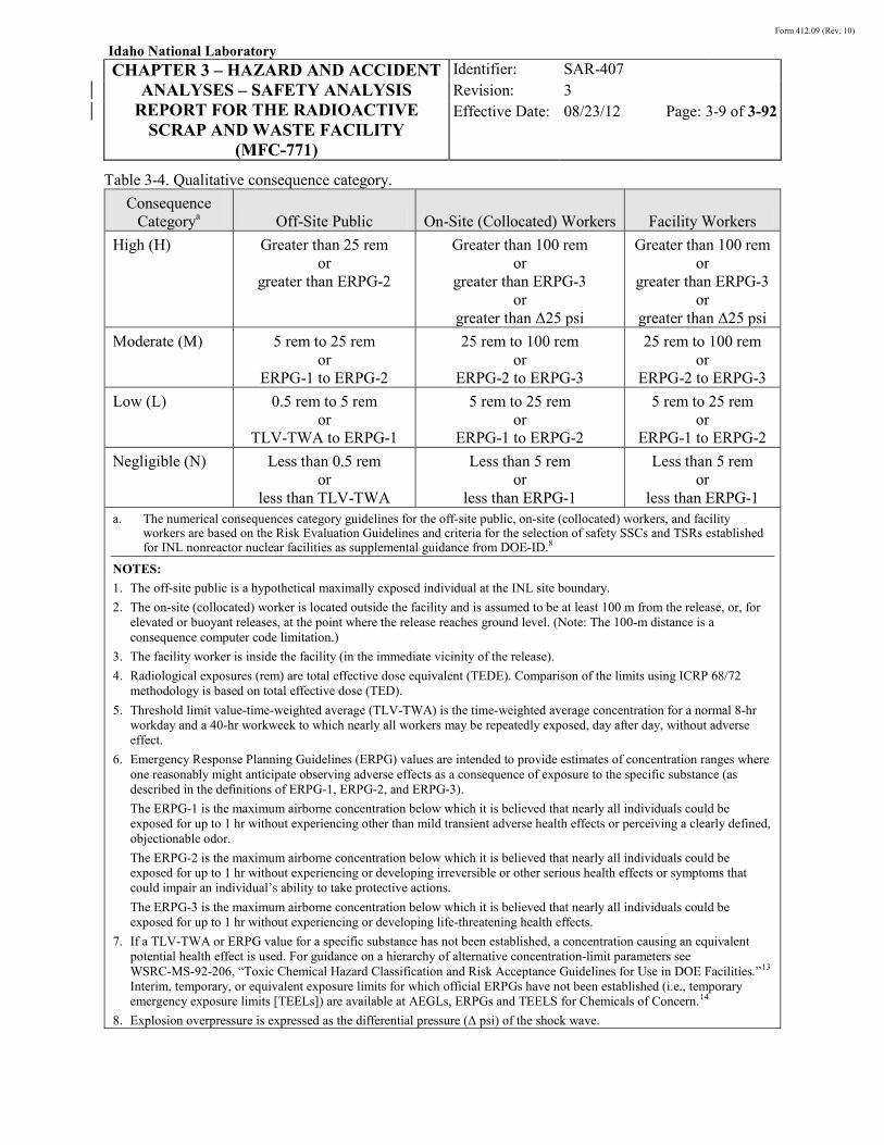
Form 412.09 (Rev. 10)
Idaho National Laboratory
CHAPTER 3 – HAZARD AND ACCIDENT ANALYSES – SAFETY ANALYSIS
REPORT FOR THE RADIOACTIVE SCRAP AND WASTE FACILITY
(MFC-771)
Identifier: Revision: Effective Date:
SAR-407 3 08/23/12 Page: 3-9 of 3-92
Table 3-4. Qualitative consequence category. Consequence
Categorya Off-Site Public On-Site (Collocated) Workers Facility Workers High (H) Greater than 25 rem
or greater than ERPG-2
Greater than 100 rem or
greater than ERPG-3 or
greater than Δ25 psi
Greater than 100 rem or
greater than ERPG-3 or
greater than Δ25 psi Moderate (M) 5 rem to 25 rem
or ERPG-1 to ERPG-2
25 rem to 100 rem or
ERPG-2 to ERPG-3
25 rem to 100 rem or
ERPG-2 to ERPG-3 Low (L) 0.5 rem to 5 rem
or TLV-TWA to ERPG-1
5 rem to 25 rem or
ERPG-1 to ERPG-2
5 rem to 25 rem or
ERPG-1 to ERPG-2 Negligible (N) Less than 0.5 rem
or less than TLV-TWA
Less than 5 rem or
less than ERPG-1
Less than 5 rem or
less than ERPG-1 a. The numerical consequences category guidelines for the off-site public, on-site (collocated) workers, and facility
workers are based on the Risk Evaluation Guidelines and criteria for the selection of safety SSCs and TSRs established for INL nonreactor nuclear facilities as supplemental guidance from DOE-ID.8
NOTES: 1. The off-site public is a hypothetical maximally exposed individual at the INL site boundary. 2. The on-site (collocated) worker is located outside the facility and is assumed to be at least 100 m from the release, or, for
elevated or buoyant releases, at the point where the release reaches ground level. (Note: The 100-m distance is a consequence computer code limitation.)
3. The facility worker is inside the facility (in the immediate vicinity of the release). 4. Radiological exposures (rem) are total effective dose equivalent (TEDE). Comparison of the limits using ICRP 68/72
methodology is based on total effective dose (TED). 5. Threshold limit value-time-weighted average (TLV-TWA) is the time-weighted average concentration for a normal 8-hr
workday and a 40-hr workweek to which nearly all workers may be repeatedly exposed, day after day, without adverse effect.
6. Emergency Response Planning Guidelines (ERPG) values are intended to provide estimates of concentration ranges where one reasonably might anticipate observing adverse effects as a consequence of exposure to the specific substance (as described in the definitions of ERPG-1, ERPG-2, and ERPG-3). The ERPG-1 is the maximum airborne concentration below which it is believed that nearly all individuals could be exposed for up to 1 hr without experiencing other than mild transient adverse health effects or perceiving a clearly defined, objectionable odor. The ERPG-2 is the maximum airborne concentration below which it is believed that nearly all individuals could be exposed for up to 1 hr without experiencing or developing irreversible or other serious health effects or symptoms that could impair an individual’s ability to take protective actions. The ERPG-3 is the maximum airborne concentration below which it is believed that nearly all individuals could be exposed for up to 1 hr without experiencing or developing life-threatening health effects.
7. If a TLV-TWA or ERPG value for a specific substance has not been established, a concentration causing an equivalent potential health effect is used. For guidance on a hierarchy of alternative concentration-limit parameters see WSRC-MS-92-206, “Toxic Chemical Hazard Classification and Risk Acceptance Guidelines for Use in DOE Facilities.”13 Interim, temporary, or equivalent exposure limits for which official ERPGs have not been established (i.e., temporary emergency exposure limits [TEELs]) are available at AEGLs, ERPGs and TEELS for Chemicals of Concern.14
8. Explosion overpressure is expressed as the differential pressure (Δ psi) of the shock wave.

Form 412.09 (Rev. 10)
Idaho National Laboratory
CHAPTER 3 – HAZARD AND ACCIDENT ANALYSES – SAFETY ANALYSIS
REPORT FOR THE RADIOACTIVE SCRAP AND WASTE FACILITY
(MFC-771)
Identifier: Revision: Effective Date:
SAR-407 3 08/23/12 Page: 3-10 of 3-92
Table 3-5. INL risk evaluation guidelines.
Event/Accident Likelihood/Frequency
Collocated and Facility Worker Consequences
Off-Site Public Consequences
Anticipated (10−2 to 10−1/yr)
Radiological 5.0 rem (TEDEa) 0.5 rem (TEDE)
Nonradiological ERPG-1 or equivalentb
TLV-TWA or equivalentc
Unlikely (10−4 to 10−2/yr)
Radiological 25 rem (TEDE) 5 rem (TEDE)
Nonradiological ERPG-2 or equivalent
ERPG-1 or equivalent
Extremely unlikely (10−6 to 10−4/yr)
Radiological 100 rem (TEDE)d 25 rem (TEDE)
Nonradiological ERPG-3 or equivalentd
ERPG-2 or equivalent
a. TEDE = Total Effective Dose Equivalent. b. ERPG = Emergency Response Planning Guidelines (American Industrial Hygiene Association). Equivalent means a
concentration of a hazardous chemical causing potential health effects similar to ERPG-1 levels, but for which an ERPG-1 concentration has not been established. Likewise, equivalent to ERPG-2 or ERPG-3 means concentrations of hazardous chemicals causing potential health effects similar to ERPG-2/3 levels, but for which ERPG-2/3 concentrations have not been established. Interim, temporary, or equivalent exposure limits for which official ERPGs have not been established (i.e., temporary emergency exposure limits [TEELs]) are available at “Protective Action Criteria (PAC) with AEGLs, ERPGs and TEELs for Chemicals of Concern.”14 See also WSRC-MS-92-206, “Toxic Chemical Hazard Classification and Risk Acceptance Guidelines for Use in DOE Facilities.”13
c. TLV-TWA = Threshold limit value–time-weighted average. Equivalent means a concentration of a hazardous chemical causing potential health effects similar to TLV-TWA levels, but for which a TLV-TWA concentration has not been established. For guidance on a hierarchy of alternative concentration-limit parameters see WSRC-MS-92-206.
d. These guidelines apply only to collocated workers, not facility workers. For most postulated accidents with some facility worker consequences, such as unshielded criticalities or process explosions, it is seldom possible to identify a consequence-mitigation barrier that will allow meeting such a guideline.
Form 412.09 (Rev. 10)
Idaho National Laboratory
CHAPTER 3 – HAZARD AND ACCIDENT ANALYSES – SAFETY ANALYSIS
REPORT FOR THE RADIOACTIVE SCRAP AND WASTE FACILITY
(MFC-771)
Identifier: Revision: Effective Date:
SAR-407 3 08/23/12 Page: 3-11 of 3-92
Based on the likelihood and consequence categories, a risk bin number was assigned using the qualitative risk matrices in Figures 3-1, 3-2, and 3-3. There is no risk bin for environmental effects. The risk bin numbers in the risk matrices indicate whether safety SSCs, TSRs, and/or safety analysis commitments should be identified to manage the risk.
Potential HEs initiated by natural phenomena were evaluated per the requirements and guidelines in DOE O 420.1B, “Facility Safety”15; DOE G 420.1-2, “Guide for the Mitigation of Natural Phenomena Hazards for DOE Nuclear Facilities”16; DOE-STD-1020-2002, “Natural Phenomena Hazards Design and Evaluation Criteria for Department of Energy Facilities”17; DOE-STD-1021-93, “Natural Phenomena Hazards Performance Categorization Guidelines for Structures, Systems, and Components”18; DOE-STD-1022-94, “Natural Phenomena Hazards Site Characterization Criteria”19; and DOE-STD-1023-95, “Natural Phenomena Hazards Assessments Criteria.”20
3.3.2.3.8 These hazards are discussed
further in Section . The likelihood category of natural phenomena events are assumed to be unlikely since the frequency of the initiating design basis NPH event is no greater than unlikely (10−4 to 10−2 per year). Consequence categories were assigned assuming the facility was not designed for the NPH and were used to identify whether any facility SSC functional or performance requirements relating to the NPH require a safety-class or safety-significant designation.
Relative to NPH, volcanic activity has been dismissed as an applicable hazard for RSWF. There are no design criteria for volcanic activity and the potential for future volcanic eruptions is considered extremely unlikely since the recurrence interval is approximately 51,000 years (see Chapter 1 of SAR-400).

Form 412.09 (Rev. 10)
Idaho National Laboratory
CHAPTER 3 – HAZARD AND ACCIDENT ANALYSES – SAFETY ANALYSIS
REPORT FOR THE RADIOACTIVE SCRAP AND WASTE FACILITY
(MFC-771)
Identifier: Revision: Effective Date:
SAR-407 3 08/23/12 Page: 3-12 of 3-92
1
1
3
3
6
6
10
10
2
2
5
5
9
9
4
4
8
8
7
7
13
13
12
12
11
11
14
14
16
16
15
15
Radiological
Nonradiological
Negligible
Negligible
Anticipated(10 - 10 )-2 -1
Unlikely(10 - 10 )-4 -2
Extremely Unlikely(10 - 10 )-6 -4
Beyond ExtremelyUnlikely (<10 )-6
Low
Low
Moderate
Moderate
Consequence Category
ConsequenceCategory
High (H)
Moderate (M)
Low (L)
Negligible (N)
Off-SitePublic
greater than 25 remor
greater than ERPG-2
5 rem to 25 remor
ERPG-1 to ERPG-2
0.5 rem to 5 remor
TLV-TWA to ERPG-1
less than 0.5 remor
less than TLV-TWA
Consequence Category
Like
lihoo
d C
ateg
ory
Like
lihoo
d C
ateg
ory
High
High
Safety-class SSCs and/or TSRs should be identified to manage off-site public risk;accident analysis may be needed.
Safety-class SSCs or TSRs are generally not required to manage off-site public risk.
KEY
02-GA51330-01
Anticipated(10 - 10 )-2 -1
Unlikely(10 - 10 )-4 -2
Extremely Unlikely(10 - 10 )-6 -4
Beyond ExtremelyUnlikely (<10 )-6
Figure 3-1. Qualitative risk matrix for the off-site public.

Form 412.09 (Rev. 10)
Idaho National Laboratory
CHAPTER 3 – HAZARD AND ACCIDENT ANALYSES – SAFETY ANALYSIS
REPORT FOR THE RADIOACTIVE SCRAP AND WASTE FACILITY
(MFC-771)
Identifier: Revision: Effective Date:
SAR-407 3 08/23/12 Page: 3-13 of 3-92
Figure 3-2. Qualitative risk matrix for on-site collocated workers.
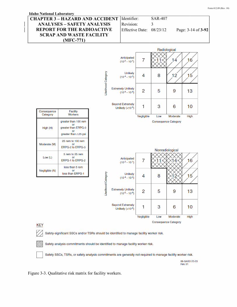
Form 412.09 (Rev. 10)
Idaho National Laboratory
CHAPTER 3 – HAZARD AND ACCIDENT ANALYSES – SAFETY ANALYSIS
REPORT FOR THE RADIOACTIVE SCRAP AND WASTE FACILITY
(MFC-771)
Identifier: Revision: Effective Date:
SAR-407 3 08/23/12 Page: 3-14 of 3-92
Figure 3-3. Qualitative risk matrix for facility workers.

Form 412.09 (Rev. 10)
Idaho National Laboratory
CHAPTER 3 – HAZARD AND ACCIDENT ANALYSES – SAFETY ANALYSIS
REPORT FOR THE RADIOACTIVE SCRAP AND WASTE FACILITY
(MFC-771)
Identifier: Revision: Effective Date:
SAR-407 3 08/23/12 Page: 3-15 of 3-92
3.3.2 Hazard Analysis Results
The results of the hazard analysis are presented and summarized in this section, which includes hazard identification, hazard categorization, and hazard evaluation results.
3.3.2.1 Hazard Identification. The non-routine material and energy hazard sources that have the potential to result in an uncontrolled release of radioactive and/or hazardous materials or other effects related to the qualitative consequence category definitions (see Table 3-4) due to RSWF operations are summarized in Table 3-6. These non-routine material and energy hazard sources could affect the off-site public, workers, or the environment. In addition to internal hazards, the non-routine hazards listed in Table 3-6 encompass potential external hazards and NPHs as identified in Chapter 1, “Site Characteristics.” These potential hazards are further evaluated in Section 3.3.2.3. Standard industrial hazards are addressed in Section 3.3.2.1.4.
Table 3-6. Summary of non-routine material and energy hazard sources. Hazard Hazard Source(s) Concern
Kinetic energy Moving loads (casks/container transfers)
Potential initiator of damage to a transfer cask or its container(s) causing a release of radioactive material or a criticality
Potential energy Suspended loads Potential for drop and subsequent damage to container(s) causing a release of radioactive material or a criticality
Pyrophoric materials
Radioactive waste; spent nuclear fuel (uranium metal; hydrides)
Potential initiator of radioactive material release
Fissionable materials
Fissionable materials in storage liners
Potential for a nuclear criticality
Hazardous materials
Hazardous material in storage liners (lead, reactive metals [Na and NaK], toxic metals)
Potential for hazardous material release and exposure
Radioactive materials
Radioactive materials in casks/containers and storage liners
Potential for radioactive material release and/or direct radiation exposure
Fire, explosion, flammable materials
Hydrogen in liners generated from internal corrosion, reactive metal-water reaction (Na, NaK), and/or radiolysis; pyrophoric metals (uranium metal; uranium hydrides); acetylene gas (liner cutting); vehicle fuel
Potential for fire or explosion causing a release of radioactive or hazardous material
Natural phenomena
Earthquake, extreme wind, flood, lightning, etc.
Potential initiator of a radioactive material release and/or direct radiation exposure
External events Range fire Potential initiator of a radioactive material release
Form 412.09 (Rev. 10)
Idaho National Laboratory
CHAPTER 3 – HAZARD AND ACCIDENT ANALYSES – SAFETY ANALYSIS
REPORT FOR THE RADIOACTIVE SCRAP AND WASTE FACILITY
(MFC-771)
Identifier: Revision: Effective Date:
SAR-407 3 08/23/12 Page: 3-16 of 3-92
3.3.2.1.1 Radioactive Material Inventory—As described in Chapter 2, the scope of operations at RSWF includes receipt, handling, storage, and retrieval of containerized remote-handled radioactive materials and waste. The spent fuel and accountable material are stored at RSWF due to the potentially recoverable quantities of uranium and/or plutonium. Remote handled mixed and radioactive waste is stored because additional characterization, segregation, and/or treatment are required, and/or because a treatment or disposal facility does not currently exist. The types and categories of radioactive material within the scope of RSWF handling and storage operations have been previously described in Chapter 2. In general terms, these types include:
• Irradiated EBR-II driver, blanket and experimental fuel elements
• Irradiated EBR-II blanket subassemblies (elements surrounded by a shortened hex can, or contained in 2.5-in. diameter stainless steel pipes)
• Irradiated stainless steel and hardware from the disassembly of EBR-II driver and blanket subassemblies and decladding of EBR-II fuel elements (may include some adherent fuel and sodium from decladding operations)
• Hot cell debris/waste, such as fume traps, melt refining crucibles, in-cell equipment/tools, wiping/wrapping materials, plastics/rags, filters, and fuel scrap
• Analytical laboratory wastes (e.g., metallurgical samples, polishing debris, absorbed liquids from analytical samples)
• Low enriched uranium (LEU) ingots
• Metallic and ceramic wastes resulting from the processing of EBR-II spent fuel (projected waste).
Historical information pertaining to radioactive materials stored at RSWF is available from liner-specific storage records. Information from many of the records is available in an electronic database, which is described in TEV-13, “History of the Radioactive Scrap and Waste Facility HERO Database.”21
3.3.2.1.2 Fissionable Material Inventory—Much of the radioactive material stored at RSWF includes fissionable nuclides (e.g., Pu-239, U-235). Fissionable nuclides are present in irradiated SNF, fuel scrap, wastes generated from hot cell operations at MFC, and other miscellaneous materials stored at RSWF. Criticality controls provide liner-specific limits for fissionable material mass based on the specific material, its form, packaging, and other factors.
The storage records and database include descriptions of the contents of specific liners; identifies liners containing RCRA hazardous metals (e.g., sodium, NaK, lead); total radioactivity in curies at the time of material placement in RSWF; container radiation dose rate; and other information. The database does not currently include isotope-specific radionuclide information, nor does it track/identify decay products. Based on available information, the total activity associated with the radioactive materials that have been stored at RSWF is approximately 15 million curies (1.5E + 07) at the time of storage (number obtained using the INL Integrated Waste Tracking System and the SEALION database developed for RSWF historical records and analysis). This activity is attributed primarily to the mixed fission and activation products associated with the EBR-II spent fuel and irradiated hardware stored at the facility.
Table 3-7 provides examples of fissionable materials stored at RSWF and their respective container-specific fissionable material mass.

Form 412.09 (Rev. 10)
Idaho National Laboratory
CHAPTER 3 – HAZARD AND ACCIDENT ANALYSES – SAFETY ANALYSIS
REPORT FOR THE RADIOACTIVE SCRAP AND WASTE FACILITY
(MFC-771)
Identifier: Revision: Effective Date:
SAR-407 3 08/23/12 Page: 3-17 of 3-92
As discussed in Section 3.3.2.1.1, fissionable material in varying forms and quantities is present in RSWF. Each type of fissionable material is contained in a unique package configuration, which is then placed in a liner, as described in Chapter 2. The examples are provided to show that many liners, in and of themselves, contain sufficient fissionable material such that criticality must be considered as a potential hazard. Because of the decoupled nature of the liners, and the dynamic nature of the facility inventory, a facility-specific bounding fissionable material inventory was not developed.
Table 3-7. Examples of fissionable materials stored at RSWF.
Fissionable Material Type Fissionable Material Quantity
EBR-II blanket subassemblies Up to six EBR-II blanket subassemblies or 2 1/2-in. diameter pipes, each containing up to 19 EBR-II blanket elements
• 700 g Pu per subassembly (historical limit)
• 4,000 g Pu per liner (historical limit)
EBR-II driver or experimental fuel elements
Up to 93 fuel elements in a fuel storage basket; two fuel storage baskets per container
• ~6,000 g U-235 (historical limit)
EBR-II blanket elements Up to 57 blanket elements in a blanket element basket
• 2,000 g Pu (historical limit)
Fissionable material in a 4-in. diameter can
9 kg U-235 equivalent, or 3 kg total fissionable material
• 1,000 g Pu plus 2000 g U-235 (historical limit)
Fissionable material with no special container requirements
250 g total fissionable material per container
• 300 g total fissionable material in any container/configuration enclosed in an outer waste can (historical limit)
350 g U-235 equivalent mass per can container
• 500 g U-235 equivalent in any container/configuration enclosed in an outer waste can (historical limit)
3.3.2.1.3 Hazardous Material Inventory—The radioactive and fissionable material
inventory discussed in Sections 3.3.2.1.1 and 3.3.2.1.2 above is also hazardous, but in the hazard analysis presented in this chapter it is considered only in the context of its radiological hazard. In addition to the radioactive/fissionable material inventory at RSWF, hazardous materials are identified in the facility inventory. Based on a review of facility storage records and the inventory database, and discussions with operations personnel, these materials include reactive metals (sodium [Na] and sodium-potassium alloy [NaK]), uranium (natural, depleted, low-enriched), and toxic metals (lead, chromium, cadmium, barium, and mercury), which are commingled with the radioactive waste stored in the liners. Lead is also present apart from the containers of radioactive material in the form of shielding. The presence of these compounds and their associated hazard is discussed below.
Form 412.09 (Rev. 10)
Idaho National Laboratory
CHAPTER 3 – HAZARD AND ACCIDENT ANALYSES – SAFETY ANALYSIS
REPORT FOR THE RADIOACTIVE SCRAP AND WASTE FACILITY
(MFC-771)
Identifier: Revision: Effective Date:
SAR-407 3 08/23/12 Page: 3-18 of 3-92
Lead is present at RSWF as a shielding material in the HFEF-5 and HFEF-14 transfer casks and FTCs (~25 ft3 for 3.5 in. Pb FTC and ~21 ft3 for 2.0 in. of Pb), as a constituent of the shield plug between the inner and outer cans of the double-can containers, as lead shot (bagged) used for temporary shielding during liner loading/unloading, in some liner shield plug assemblies, and as a commingled material in hot cell debris/waste. The lead associated with the cask, FTC, liner and container shielding is not present in a readily releasable form conducive to inhalation or ingestion. There is no limit on the amount of lead listed in 40 CFR 302, “Designation, Reportable Quantities, and Notification,”22
Reactive metals present at RSWF include Na and NaK. The NaK is an extremely reactive alloy composed of 22% sodium and 78% potassium that is a liquid at room temperature. The Na is present as a bonding agent between the fuel slug and cladding of EBR-II driver, blanket, and experimental fuel elements. In addition, radiologically-contaminated sodium is also present at RSWF in bulk quantities in a limited number of liners, as well as an adherent to fuel scrap/chips. Na and NaK are of concern because they react readily with water to produce hydrogen. Hydrogen, in turn, presents a fire/explosion hazard. The reaction of Na and NaK with water also produces oxides and hydroxides of sodium and potassium.
Table 302.4, provided that the form (particle size) is greater than 100 microns (0.004 in.) in diameter. Therefore, lead in this form is not considered a respirable hazard or reportable, and is not considered further in the hazard analysis.
The potassium in NaK can react with air (oxygen) to form potassium oxide (K2O), potassium peroxide (K2O2), and potassium superoxide (KO2). These oxides form a crust over the NaK surface. If the crust is permeated and the superoxide (KO2) is allowed to mix with the NaK, a high temperature thermite-type reaction can occur.23 A thermitic reaction is exothermic but does not result in the generation of gaseous byproduct; therefore, a thermitic reaction is not an explosive hazard.24 In addition, the mixing of NaK and/or potassium superoxide with liquid hydrocarbons (e.g., mineral oil, fuel oil) can generate shock-sensitive byproducts, which can result in an explosion hazard.25,26
Wastes containing Na and NaK are identified as hazardous substances and RCRA waste streams with the characteristic of ignitability (Na) and/or reactivity (Na and NaK) in Table 302.4 of 40 CFR 302; the reportable quantity (RQ) of both materials is 100 lb (45.4 kg). The total inventory of Na at RSWF is approximately 1,375 kg (contained in approximately 240 liners) while the largest single-liner quantity of Na is 680 kg (contained in a cold trap). The facility total and several single-liner quantities exceed the RQ for Na. The total quantity of NaK located at RSWF is estimated to be 1.0 kg, contained in eight liners; the largest single-liner quantity is 0.6 kg. Table 302.4 of 40 CFR 302 does not specifically identify an RQ for NaK. Both Na and NaK are included in the hazard analysis as an initiator for a potential release of radioactive materials.
Toxic metals, cadmium, chromium, lead, mercury and barium are also identified in the RSWF inventory as RCRA waste streams. These metals are commingled with radioactive wastes stored at the facility. They are identified in 40 CFR 302.2, Table 302.4, as hazardous substances and RCRA waste streams with the characteristics of toxicity. The RQ for these toxic metals, as listed in Table 302.4, is 10 lb (4.54 kg) for cadmium, chromium, and lead; 1 lb (0.454 kg) for mercury; and 1,000 lb (454 kg) for barium. The threshold planning quantities (TPQs) listed in Appendix A of 40 CFR 355, “Emergency Planning and Notification,”27 for the oxides of cadmium and mercury as powders with a particle size less than 100 microns (0.004 in.), are 100 and 500 lb, respectively. The TPQ for chromic chloride in powder form is listed as 1 lb. (Appendix A of 40 CFR 355 does not identify lead or chromium.) None of these metals are listed in Appendix A of 29 CFR 1910.119.
Form 412.09 (Rev. 10)
Idaho National Laboratory
CHAPTER 3 – HAZARD AND ACCIDENT ANALYSES – SAFETY ANALYSIS
REPORT FOR THE RADIOACTIVE SCRAP AND WASTE FACILITY
(MFC-771)
Identifier: Revision: Effective Date:
SAR-407 3 08/23/12 Page: 3-19 of 3-92
A review of the toxic metal content associated with several waste containers stored at RSWF found that the mass of all of the metals in the commingled waste was generally very small (i.e., on the order of a few grams for a container/liner). The maximum mass in one container was 236 g (~0.5 lb) of cadmium. While not all-inclusive, the results are thought to be representative of the material stored at RSWF. Controls derived to address risks associated with the radioactive material are qualitatively judged to provide adequate protection against the potential release of these hazardous metals because their quantities are less than the applicable thresholds and RQs for RCRA waste streams identified above, and because they are commingled with radioactive material. Therefore, these metals are not considered further from the perspective of hazardous material releases.
Uranium is a concern from a hazardous material perspective in that low-enriched, natural, and depleted uranium could potentially pose a toxicological risk that outweighs its inherent radiological risk. Per DOE-STD-1136, “Guide of Good Practices for Occupational Radiological Protection in Uranium Facilities,”28
3.3.2.1.4 Standard Industrial Hazards—
the toxicological risk of uranium outweighs the radiological risk when the material is in a soluble form and the enrichment is less than 10%. While there is uranium stored at RSWF that meets the criteria described in DOE-STD-1136 (e.g., less than 10% enrichment), the uranium has either been irradiated (e.g., blanket fuel containing inbred plutonium and mixed fission/activation products), is commingled with the remote-handled radioactive materials stored in the liners, or is not readily dispersible. The toxicological risk associated with a potential release of uranium material at RSWF is qualitatively judged to be adequately bounded by the radiological risk associated with the commingled radioactive material. Therefore, uranium is not considered further from the perspective of a hazardous material release in this SAR.
Table 3-8 identifies standard industrial hazards associated with RSWF, its operations, and the DOE-prescribed OSH standards that prevent or protect against them. Standard industrial hazards are hazards that are routinely encountered in general industry and construction; for these, national consensus codes and/or standards, such as Occupational Safety and Health Administration (OSHA) standards, exist to guide safe design and operation. In accordance with the guidance in DOE-STD-1027-92 and DOE-STD-3009-94, no special analysis is required for these occupational hazards unless they are possible initiators for an uncontrolled release of radioactive or hazardous material. This hazard analysis includes events associated with initiators of this type, including hydrogen and alkali metals (Na and NaK).
3.3.2.2 Hazard Categorization. 10 CFR 830, Subpart B, defines hazard categories for nuclear facilities and operations as follows:
Hazard Category 1 The facility has the potential for significant off-site consequences.
Hazard Category 2 The facility has the potential for significant on-site consequences beyond localized consequences.
Hazard Category 3 The facility has the potential for significant localized consequences.
DOE-STD-1027-92 provides a uniform methodology for hazard categorization that meets the requirements of 10 CFR 830, Subpart B.
Form 412.09 (Rev. 10)
Idaho National Laboratory
CHAPTER 3 – HAZARD AND ACCIDENT ANALYSES – SAFETY ANALYSIS
REPORT FOR THE RADIOACTIVE SCRAP AND WASTE FACILITY
(MFC-771)
Identifier: Revision: Effective Date:
SAR-407 3 08/23/12 Page: 3-20 of 3-92
The radioactivity associated with the material placed in RSWF (at the time of placement, without subsequent decay) was 1.5E+07 curies, per facility records. While much of the material has undergone radioactive decay during storage at RSWF, and transfers of materials in and out of the facility result in frequent changes to the overall inventory, it is evident that the total activity associated with the RSWF is still significant. In addition to the radionuclide quantity, the inventory of fissionable material at RSWF also presents the potential for an inadvertent nuclear criticality (see Chapter 6) due to the presence of greater than 700 g of U-235, and greater than 450 g of Pu-239, on an aggregate as well as a liner basis. Therefore, the RSWF is a HC-2 nuclear facility based on both radionuclide and fissionable material quantities. The HC-2 designation is also substantiated by the results of the accident analysis in Section 3.4 (see Section 3.4.2.3).

Form 412.09 (Rev. 10)
Idaho National Laboratory
CHAPTER 3 – HAZARD AND ACCIDENT ANALYSES – SAFETY ANALYSIS
REPORT FOR THE RADIOACTIVE SCRAP AND WASTE FACILITY
(MFC-771)
Identifier: Revision: Effective Date:
SAR-407 3 08/23/12 Page: 3-21 of 3-92
Table 3-8. Standard industrial hazards regulated by DOE-prescribed OSH standards.
Hazard
Applicable to Facility (Yes/No) DOE-Prescribed Program and OSH Standards
High voltage (≥600 V) No 29 CFR 1910 Subpart S; National Electric Code (National Fire Protection Administration [NFPA] 70E)
Low voltage (<600 V) Yes 29 CFR 1910 Subpart S; NEC 70 Volatile flammable or reactive gases or liquids
Yes 29 CFR 1910 Subpart H, .144, .253; .1200; 29 CFR 1926.152
Explosive materials No 29 CFR 1910.109; DOE Explosive Safety Manual (DOE Manual 440.1-1)
Cryogenic systems No None of the DOE-prescribed standards clearly address cryogenics High temperature (≥125°F at contact or 203°F)
No American Society of Mechanical Engineers (ASME) Boiler and Pressure Vessel Code, ANSI/ASME Standard B31
High pressure (≥15 psig for gas or vapor or ≥200 psig for liquids)
Yes ASME Boiler and Pressure Vessel Code, ANSI/ASME Standard B31
Low pressure No ASME Boiler and Pressure Vessel Code, ANSI/ASME Standard B31 Inert and low-oxygen atmospheres No 29 CFR 1910.119, .120, .1200; 29 CFR 1926.651 Toxic materials Yes 29 CFR 1910.119, .120, .1200, Subpart Z; 29 CFR 1926.353;
American Conference of Governmental Industrial Hygienists (ACGIH) Threshold Limit Values (TLVs)
Nonionizing radiation No 29 CFR 1910.97; ACGIH TLVs High intensity magnetic fields No ACGIH TLVs High noise levels Yes 29 CFR 1910.95, .1200; 29 CFR 1926.52; ACGIH TLVs Mechanical and moving equipment dangers
Yes 29 CFR 1910.147, .211 through 222; 29 CFR 1910 Subparts O, P, Q; 29 CFR 1926 Subpart W
Working at heights Yes 29 CFR 1910.25, .28; 29 CFR 1926.951, .451 Excavation Yes 29 CFR 1926 Subpart P Material handling dangers Yes 29 CFR 1910.120, .176 through .182; 29 CFR 1926.953;
DOE-STD-1090-2007 Hoisting and Rigging Material transportation No Hazardous Material Transportation Program, DOE Orders 460.1B and
460.2A Pesticide use No 29 CFR 1910.1200 Temperature extremes (high and low temperatures during activities)
Yes 29 CFR 1910.120, .1200; ACGIH TLVs
Inadequate illumination No 29 CFR 1910.37, .68, .120, .177 through .179, .219, .303; 29 CFR 1926.26
Construction Yes 29 CFR 1926 Ionizing radiation Yes Radiation Protection Program, 10 CFR 835 Reactive materials: Alkali metal and corrosives
Yes 10 CFR 851
Structural or natural phenomena Yes DOE O 420.1B, DOE G 420.1-2, 29 CFR 1910.119, Subpart E
Fire Yes Fire Protection Program, DOE Order 420.1B Biological agents No None of the DOE-prescribed standards clearly address biological
agents. Other Yes 29 CFR 1903.1 (General Duty Clause)

Form 412.09 (Rev. 10)
Idaho National Laboratory
CHAPTER 3 – HAZARD AND ACCIDENT ANALYSES – SAFETY ANALYSIS
REPORT FOR THE RADIOACTIVE SCRAP AND WASTE FACILITY
(MFC-771)
Identifier: Revision: Effective Date:
SAR-407 3 08/23/12 Page: 3-22 of 3-92
3.3.2.3 Hazard Evaluation. The facility hazards identified in Section 3.3.2.1 that could result in an uncontrolled release of radioactive or hazardous materials or pose a direct radiation exposure hazard were evaluated using the methodology described in Section 3.3.1.2. The results of the hazard evaluation are discussed in this section. This section is organized as follows:
• Fire and explosion (Section 3.3.2.3.1)
• Radioactive material release – facility operations (Section 3.3.2.3.2)
• Radioactive material release – other (Section 3.3.2.3.3)
• Direct radiation exposure (Section 3.3.2.3.4)
• Hazardous material release (Section 3.3.2.3.5)
• Inadvertent nuclear criticality (Section 3.3.2.3.6)
• External events (Section 3.3.2.3.7)
• Natural phenomena hazards (Section 3.3.2.3.8).
The discussions in Section 3.3.2.3.1 through 3.3.2.3.8 provide a statement of the hazards or HEs and a case-specific conclusion. Sections 3.3.2.3.9 through 3.3.2.3.14 are summary sections addressing the topics cited below.a
3.3.2.3.1
The summary information presented for the defense-in-depth and worker safety sections lists the controls (i.e., the safety-significant SSCs, TSRs, and safety requirements) derived from the hazard evaluation (per Sections through 3.3.2.3.8).
• Summary (Section 3.3.2.3.9)
• Planned design and operational safety improvements (Section 3.3.2.3.10)
• Defense-in-depth (Section 3.3.2.3.11)
• Worker safety (Section 3.3.2.3.12)
• Environmental protection (Section 3.3.2.3.13)
• Accident selection (Section 3.3.2.3.14).
a. Note that this format for the hazards evaluation parallels that required by DOE-STD-3009-94, but there are more sections
provided so that the text corresponds to the layout of the hazards evaluation summary table.

Form 412.09 (Rev. 10)
Idaho National Laboratory
CHAPTER 3 – HAZARD AND ACCIDENT ANALYSES – SAFETY ANALYSIS
REPORT FOR THE RADIOACTIVE SCRAP AND WASTE FACILITY
(MFC-771)
Identifier: Revision: Effective Date:
SAR-407 3 08/23/12 Page: 3-23 of 3-92
Sections 3.3.2.3.1 through 3.3.2.3.8 are set up to parallel the same categories of hazards presented in the hazard evaluation table. The table can be used as a summation of the hazard evaluation; the text is intended as an accompaniment to the table that provides more detailed explanation where necessary. The principal purpose of the text is to clearly state the controls, TSRs, safety SSCs, and safety analysis commitments, for each individual table entry. These controls are shown in the table as bold/italic text and are derived from the analysis in accordance with risk binning methodology discussed previously. Other items are listed in the table but are not selected as part of the formal control set. These other items can consist of facility and equipment features, program controls, etc., that provide additional preventive and/or mitigative benefit for those hazard scenarios requiring controls. These additional features are also listed for hazard scenarios not requiring formal derived controls (i.e., TSRs, safety SSCs, and safety analysis commitments). The use of this presentation convention in the hazard evaluation results clearly delineates the derived control set and provides additional relevant information. These additions also serve to integrate Chapter 2 descriptive information and institutional safety program information into the hazard analysis results.
This SAR establishes safety-significant SSCs and/or TSR-level controls for all HEs or postulated accidents that challenge or exceed risk evaluation guidelines without controls. If needed, safety analysis commitments are also defined for collocated and facility worker risk, consistent with the risk bin definitions depicted in Figures 3-2 and 3-3, respectively. This hierarchy of TSR and safety requirement controls satisfies all DOE and DOE-ID TSR requirements and guidelines.
Sections 3.3.2.3.1 through 3.3.2.3.8, and the summary Sections 3.3.2.3.9 through 3.3.2.3.14, present the results of the hazard evaluation, including the discussion on criticality safety contained in Chapter 6. As shown in Table 3-9, for all HEs where the estimated risk, in the absence of controls, challenged or exceeded established guidelines, safety SSCs, TSRs, and/or safety analysis commitments are identified to reduce the risk below Risk Evaluation Guidelines. Safety SSCs and TSRs were also identified if they provided significant defense-in-depth. The risk bins, and consequence and likelihood categories, have been previously defined in Section 3.3.1.2 and in Figures 3-1, 3-2, and 3-3.
The summary sections also address program controls that are necessary for a defense-in-depth approach to facility safety. Since they are usually not explicitly derived from the analysis of the individual HEs, they are not shown on the hazard evaluation table or discussed in the associated text unless of specific importance to the HE. These program controls include training, procedures, configuration management, etc., that are important to safe operation. A comprehensive listing of these program controls is provided in Section 3.3.2.3.12.
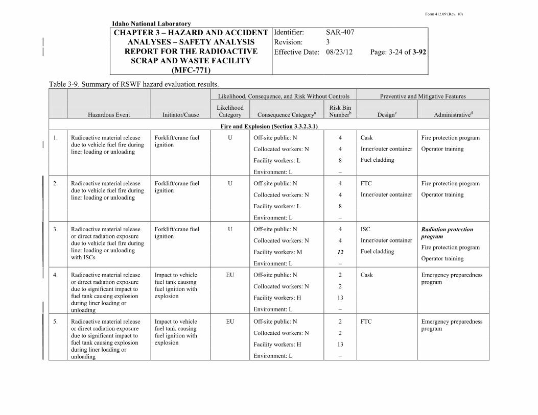
Form 412.09 (Rev. 10)
Idaho National Laboratory
CHAPTER 3 – HAZARD AND ACCIDENT ANALYSES – SAFETY ANALYSIS
REPORT FOR THE RADIOACTIVE SCRAP AND WASTE FACILITY
(MFC-771)
Identifier: Revision: Effective Date:
SAR-407 3 08/23/12 Page: 3-24 of 3-92
Table 3-9. Summary of RSWF hazard evaluation results.
Hazardous Event Initiator/Cause
Likelihood, Consequence, and Risk Without Controls Preventive and Mitigative Features
Likelihood Category Consequence Categorya
Risk Bin Numberb Designc Administratived
Fire and Explosion (Section 3.3.2.3.1)
1. Radioactive material release due to vehicle fuel fire during liner loading or unloading
Forklift/crane fuel ignition
U Off-site public: N 4 Cask
Inner/outer container
Fuel cladding
Fire protection program
Operator training Collocated workers: N 4
Facility workers: L 8
Environment: L –
2. Radioactive material release due to vehicle fuel fire during liner loading or unloading
Forklift/crane fuel ignition
U Off-site public: N 4 FTC
Inner/outer container
Fire protection program
Operator training Collocated workers: N 4
Facility workers: L 8
Environment: L –
3. Radioactive material release or direct radiation exposure due to vehicle fuel fire during liner loading or unloading with ISCs
Forklift/crane fuel ignition
U Off-site public: N 4 ISC
Inner/outer container
Fuel cladding
Radiation protection program
Fire protection program
Operator training
Collocated workers: N 4
Facility workers: M 12
Environment: L –
4. Radioactive material release or direct radiation exposure due to significant impact to fuel tank causing explosion during liner loading or unloading
Impact to vehicle fuel tank causing fuel ignition with explosion
EU Off-site public: N 2 Cask Emergency preparedness program
Collocated workers: N 2
Facility workers: H 13
Environment: L –
5. Radioactive material release or direct radiation exposure due to significant impact to fuel tank causing explosion during liner loading or unloading
Impact to vehicle fuel tank causing fuel ignition with explosion
EU Off-site public: N 2 FTC Emergency preparedness program
Collocated workers: N 2
Facility workers: H 13
Environment: L –

Form 412.09 (Rev. 10)
Idaho National Laboratory
CHAPTER 3 – HAZARD AND ACCIDENT ANALYSES – SAFETY ANALYSIS
REPORT FOR THE RADIOACTIVE SCRAP AND WASTE FACILITY
(MFC-771)
Identifier: Revision: Effective Date:
SAR-407 3 08/23/12 Page: 3-25 of 3-92
Table 3-9. (continued).
Hazardous Event Initiator/Cause
Likelihood, Consequence, and Risk Without Controls Preventive and Mitigative Features
Likelihood Category Consequence Categorya
Risk Bin Numberb Designc Administratived
6. Radioactive material release due to ignition of flammable gas mixture in storage liner
Hydrogen accumulation (corrosion, radiolysis; Na/NaK-water reaction); oxygen present; ignition source (drilling, purging, cutting)
A Off-site public: N 7 Liner
Radioactive material containment (fuel cladding, inner/outer cans, legacy liners)
Remote liner drilling
Liner purging/venting
Operator training
Emergency preparedness program
Collocated workers: N 7
Facility workers: L 11
Environment: L –
7. Radioactive material release due to container fire/deflagration
Pyrophoric materials (U metal, hydrides); reactive metals; hydrogen, oxygen present; ignition sources
EU Off-site public: N 2 Radioactive material packaging (inner/outer can; legacy liner; fuel cladding)
Radiation protection program
Collocated workers: N 2
Facility workers: L 5
Environment: L –
Radioactive Material Release (Section 3.3.2.3.2)
8. Radioactive material release during liner opening (fission gas)
Operator error, equipment failure
A Off-site public: N 7 Containers (inner/outer cans)
Fuel cladding
Radiation protection program
Approved procedures Collocated workers: N 7
Facility workers: N 7
Environment: N –
9. Radioactive material release from liner drop or failure during lifting and handling of a loaded liner
Operator error, equipment failure
A Off-site public: N 7 Liner Hoisting and rigging program
Radiation protection program
Collocated workers: N 7
Facility workers: L 11
Environment: L –

Form 412.09 (Rev. 10)
Idaho National Laboratory
CHAPTER 3 – HAZARD AND ACCIDENT ANALYSES – SAFETY ANALYSIS
REPORT FOR THE RADIOACTIVE SCRAP AND WASTE FACILITY
(MFC-771)
Identifier: Revision: Effective Date:
SAR-407 3 08/23/12 Page: 3-26 of 3-92
Table 3-9. (continued).
Hazardous Event Initiator/Cause
Likelihood, Consequence, and Risk Without Controls Preventive and Mitigative Features
Likelihood Category Consequence Categorya
Risk Bin Numberb Designc Administratived
10. Radioactive material release from SNF/accountable material container (double can) drop due to load linkage failure
Operator error, equipment failure
U Off-site public: N 4 Inner/outer container package
Fuel cladding
Container handling limit
Hoisting and rigging program
Radiation protection program
Collocated workers: N 4
Facility workers: M 12
Environment: L –
11. Radioactive material release from waste container (double can) drop due to load linkage failure
Operator error, equipment failure
U Off-site public: N 4 Inner/outer container package
Hoisting and rigging program
Radiation protection program
Collocated workers: N 4
Facility workers: L 8
Environment: L –
12. Radioactive material release from multiple waste container (double can) breach due to load linkage failure
Operator error, equipment failure
EU Off-site public: N 2 Inner/outer container package
Hoisting and rigging program
Radiation protection program
Collocated workers: N 2
Facility workers: M 9
Environment: L –
13. Radioactive material release due to liner/container breach resulting from heavy object impact or load (e.g., forklift/cask, shield plug)
Operator error, equipment failure
A Off-site public: N 7 Liner/shield plug Radiation protection program
Procedural requirement
Operator training
Collocated workers: N 7
Facility workers: L 11
Environment: L –
14. Radioactive material release due to liner/container breach resulting from heavy object load on 48-in. and /or 60-in. liners (e.g., forklift/cask, shield plug)
Operator error, equipment failure
A Off-site public: N 7 Radiation protection program
Procedural requirement
Operator training
Collocated workers: N 7
Facility workers: L 11
Environment: L –

Form 412.09 (Rev. 10)
Idaho National Laboratory
CHAPTER 3 – HAZARD AND ACCIDENT ANALYSES – SAFETY ANALYSIS
REPORT FOR THE RADIOACTIVE SCRAP AND WASTE FACILITY
(MFC-771)
Identifier: Revision: Effective Date:
SAR-407 3 08/23/12 Page: 3-27 of 3-92
Table 3-9. (continued).
Hazardous Event Initiator/Cause
Likelihood, Consequence, and Risk Without Controls Preventive and Mitigative Features
Likelihood Category Consequence Categorya
Risk Bin Numberb Designc Administratived
15. Radioactive material release due to cask drop during in-facility container movement operations
Operator error; equipment failure
U Off-site public: N 4 Cask RSWF in-facility movements
Radiation protection program
Collocated workers: N 4
Facility workers: M 12
Environment: L –
16. Radioactive material release due to FTC drop during in-facility container movement operations
Operator error, equipment failure
A Off-site public: N 7 FTC RSWF in-facility movements
Radiation protection program
Collocated workers: N 7
Facility workers: M 14
Environment: L –
17. Radioactive material release due to ISC drop during in-facility container movement operations
Operator error, equipment failure
A Off-site public: N 7 ISC RSWF in-facility movements
Radiation protection program
Collocated workers: L 11
Facility workers: M 14
Environment: L –
18. Radioactive material release from non-standard package drop during handling/transfer mishap
Operator error, equipment failure
U Off-site public: N 4 Container Hoisting and rigging program
Collocated workers: N 4
Facility workers: N 4
Environment: N –
19. Radioactive material release due to liner breach during soil excavation
Operator error; equipment failure
A Off-site public: N 7 Operator training
Approved procedures Collocated workers: N 7
Facility workers: N 7
Environment: L –

Form 412.09 (Rev. 10)
Idaho National Laboratory
CHAPTER 3 – HAZARD AND ACCIDENT ANALYSES – SAFETY ANALYSIS
REPORT FOR THE RADIOACTIVE SCRAP AND WASTE FACILITY
(MFC-771)
Identifier: Revision: Effective Date:
SAR-407 3 08/23/12 Page: 3-28 of 3-92
Table 3-9. (continued).
Hazardous Event Initiator/Cause
Likelihood, Consequence, and Risk Without Controls Preventive and Mitigative Features
Likelihood Category Consequence Categorya
Risk Bin Numberb Designc Administratived
20. Radioactive material release during liner purging
Operator error, equipment failure
A Off-site public: N 7 Liner design
Container design
Drilling/purging equipment
Approved procedures
Collocated workers: N 7
Facility workers: N 7
Environment: L –
Radioactive Material Release – Other (Section 3.3.2.3.3)
21. Radioactive material release due to corrosion of liners
Internal and/or external corrosion
A Off-site public: N 7 Cathodic protection system
Approved procedures
Collocated workers: N 7
Facility workers: N 7
Environment: L –
Direct Radiation Exposure (Section 3.3.2.3.4)
22. Direct radiation exposure resulting from corrosion of liners
Shielding removal, operator error
A Off-site public: N 7 Cathodic protection system
Container handling limit
Radiation protection program
Emergency preparedness program
Collocated workers: N 7
Facility workers: H 16
Environment: L –
23. Direct radiation exposure resulting from open cask (e.g., shield doors, lid)
Shielding removal, operator error
A Off-site public: N 7 Cask Radiation protection program
Operator training Collocated workers: N 7
Facility workers: N 7
Environment: N –

Form 412.09 (Rev. 10)
Idaho National Laboratory
CHAPTER 3 – HAZARD AND ACCIDENT ANALYSES – SAFETY ANALYSIS
REPORT FOR THE RADIOACTIVE SCRAP AND WASTE FACILITY
(MFC-771)
Identifier: Revision: Effective Date:
SAR-407 3 08/23/12 Page: 3-29 of 3-92
Table 3-9. (continued).
Hazardous Event Initiator/Cause
Likelihood, Consequence, and Risk Without Controls Preventive and Mitigative Features
Likelihood Category Consequence Categorya
Risk Bin Numberb Designc Administratived
24. Direct radiation exposure resulting from open cask or FTC (e.g., shield doors, lid)
Shielding removal, operator error
A Off-site public: N 7 FTC Radiation protection program
Operator training Collocated workers: N 7
Facility workers: N 7
Environment: N –
25. Direct radiation exposure resulting from open liner
Shielding removal, operator error
A Off-site public: N 7 Liner location (underground)
Radiation protection program
Operator training Collocated workers: N 7
Facility workers: N 7
Environment: N –
26. Direct radiation exposure resulting from liner loading/unloading with a cask
Shielding removal, operator error
U Off-site public: N 4 Cask
Cask positioning devices
Cask seating requirement
Staffing requirement
Supplemental radiological control
Radiation protection program
Operator training
Collocated workers: N 4
Facility workers: H 15
Environment: N –
27. Direct radiation exposure resulting from liner loading/unloading with an FTC
Shielding removal, operator error
U Off-site public: N 4 FTC
FTC receiving station
Staffing requirement
Supplemental radiological control
Radiation protection program
Operator training
Collocated workers: N 4
Facility workers: M 12
Environment: N –
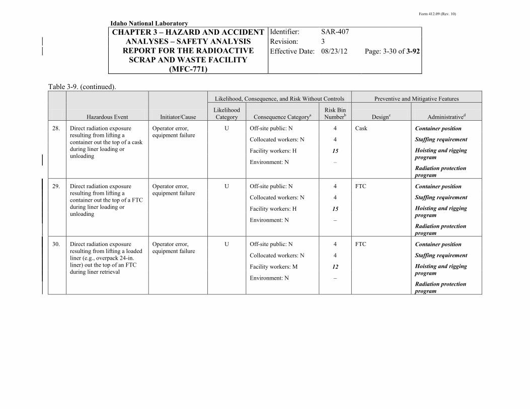
Form 412.09 (Rev. 10)
Idaho National Laboratory
CHAPTER 3 – HAZARD AND ACCIDENT ANALYSES – SAFETY ANALYSIS
REPORT FOR THE RADIOACTIVE SCRAP AND WASTE FACILITY
(MFC-771)
Identifier: Revision: Effective Date:
SAR-407 3 08/23/12 Page: 3-30 of 3-92
Table 3-9. (continued).
Hazardous Event Initiator/Cause
Likelihood, Consequence, and Risk Without Controls Preventive and Mitigative Features
Likelihood Category Consequence Categorya
Risk Bin Numberb Designc Administratived
28. Direct radiation exposure resulting from lifting a container out the top of a cask during liner loading or unloading
Operator error, equipment failure
U Off-site public: N 4 Cask Container position
Staffing requirement
Hoisting and rigging program
Radiation protection program
Collocated workers: N 4
Facility workers: H 15
Environment: N –
29. Direct radiation exposure resulting from lifting a container out the top of a FTC during liner loading or unloading
Operator error, equipment failure
U Off-site public: N 4 FTC Container position
Staffing requirement
Hoisting and rigging program
Radiation protection program
Collocated workers: N 4
Facility workers: H 15
Environment: N –
30. Direct radiation exposure resulting from lifting a loaded liner (e.g., overpack 24-in. liner) out the top of an FTC during liner retrieval
Operator error, equipment failure
U Off-site public: N 4 FTC Container position
Staffing requirement
Hoisting and rigging program
Radiation protection program
Collocated workers: N 4
Facility workers: M 12
Environment: N –

Form 412.09 (Rev. 10)
Idaho National Laboratory
CHAPTER 3 – HAZARD AND ACCIDENT ANALYSES – SAFETY ANALYSIS
REPORT FOR THE RADIOACTIVE SCRAP AND WASTE FACILITY
(MFC-771)
Identifier: Revision: Effective Date:
SAR-407 3 08/23/12 Page: 3-31 of 3-92
Table 3-9. (continued).
Hazardous Event Initiator/Cause
Likelihood, Consequence, and Risk Without Controls Preventive and Mitigative Features
Likelihood Category Consequence Categorya
Risk Bin Numberb Designc Administratived
31. Direct high-level radiation exposure during open-air transfer of containers, loaded liners, or overpack liners to storage liners, storage units, or transfer containers
Improper retrieval/transfer operations, equipment failure, operator error
A Off-site public: N 7 None Staffing requirement
Hoisting and rigging program
Supplemental radiological control
Radiation protection program
Operator training
Collocated workers: N 7
Facility workers: H 16
Environment: N –
32. Direct radiation exposure resulting from excessive excavation of soil from around liner
Operator error U Off-site public: N 4 Soil Soil excavation control
Radiation protection program
Operator training
Collocated workers: N 4
Facility workers: H 15
Environment: N –
33. Direct radiation exposure resulting from installation of 30-in. liners and loading and unloading 30-in. liners
Operator error U Off-site public: N 4 Soil Soil excavation control
Radiation protection program
Operator training
Collocated workers: N 4
Facility workers: H 15
Environment: N –
34. Direct radiation exposure resulting from heavy object impact on liner (e.g., cask, FTC, vehicle)
Operator error, equipment failure
U Off-site public: N 4 Liner
Liner shield plug
Radiation protection program
Operator training Collocated workers: N 4
Facility workers: N 4
Environment: N –

Form 412.09 (Rev. 10)
Idaho National Laboratory
CHAPTER 3 – HAZARD AND ACCIDENT ANALYSES – SAFETY ANALYSIS
REPORT FOR THE RADIOACTIVE SCRAP AND WASTE FACILITY
(MFC-771)
Identifier: Revision: Effective Date:
SAR-407 3 08/23/12 Page: 3-32 of 3-92
Table 3-9. (continued).
Hazardous Event Initiator/Cause
Likelihood, Consequence, and Risk Without Controls Preventive and Mitigative Features
Likelihood Category Consequence Categorya
Risk Bin Numberb Designc Administratived
35. Direct radiation exposure due to radioactive material stored in closed liner array
Normal facility operations
A Off-site public: N 7 Liner shield plug
Container shield plug
Soil
Collocated workers: N 7
Facility workers: N 7
Environment: N –
36. Direct high radiation exposure resulting from radioactive material handled or stored in FTC or ISC
Shielding design criteria exceeded
A Off-site public: N 4 FTC, ISC Supplemental radiological control
Radiation protection program
Collocated workers: N 4
Facility workers: M 14
Environment: N –
37. Direct radiation exposure resulting from radioactive material handled or stored in closed transfer cask
Normal facility operations
A Off-site public: N 7 Cask
Collocated workers: N 7
Facility workers: N 7
Environment: N –
38. Direct radiation exposure resulting from radioactive material handled or stored in closed FTC or ISC
Normal facility operations
A Off-site public: N 7 FTC, ISC
Collocated workers: N 7
Facility workers: N 7
Environment: N –
39. Direct radiation exposure from non-standard package during handling/transfer
Normal facility operations
A Off-site public: N 7 Container shielding Radiation protection program
Operator training Collocated workers: N 7
Facility workers: L 11
Environment: N –

Form 412.09 (Rev. 10)
Idaho National Laboratory
CHAPTER 3 – HAZARD AND ACCIDENT ANALYSES – SAFETY ANALYSIS
REPORT FOR THE RADIOACTIVE SCRAP AND WASTE FACILITY
(MFC-771)
Identifier: Revision: Effective Date:
SAR-407 3 08/23/12 Page: 3-33 of 3-92
Table 3-9. (continued).
Hazardous Event Initiator/Cause
Likelihood, Consequence, and Risk Without Controls Preventive and Mitigative Features
Likelihood Category Consequence Categorya
Risk Bin Numberb Designc Administratived
Hazardous Material Release (Section 3.3.2.3.5)
40. Release of hazardous materials (e.g., toxic metals) due to container failure or fire/explosion
See Sections 3.3.2.1.3 and 3.3.2.3.5 for discussion of hazardous materials at RSWF.
Inadvertent Nuclear Criticality (Section 3.3.2.3.6)
41. Inadvertent nuclear criticality Handling and storage scenarios (see Chapter 6)
U Off-site public: N 4 Criticality safety controls (see Chapter 6)
Collocated workers: H 15
Facility workers: H 15
Environment: N –
External Events (Section 3.3.2.3.7)
42. Release of radioactive material due to range fire
Range fire EU Off-site public: N 2 Liner location (underground)
Facility maintenance (weed/brush control)
Fire protection program
Emergency preparedness program
Collocated workers: N 2
Facility workers: N 2
Environment: N –
Natural Phenomena Hazards (Section 3.3.2.3.8)
43. Radioactive material release and/or direct radiation exposure due to seismic load
Seismic event, saturated soil
EU Off-site public: N E Cask, FTC, ISC
Containment (fuel cladding, inner/outer can, liner)
RSWF-in facility movements
Radiation protection program
Emergency preparedness program
Collocated workers: L E
Facility workers: H E
Environment: M –
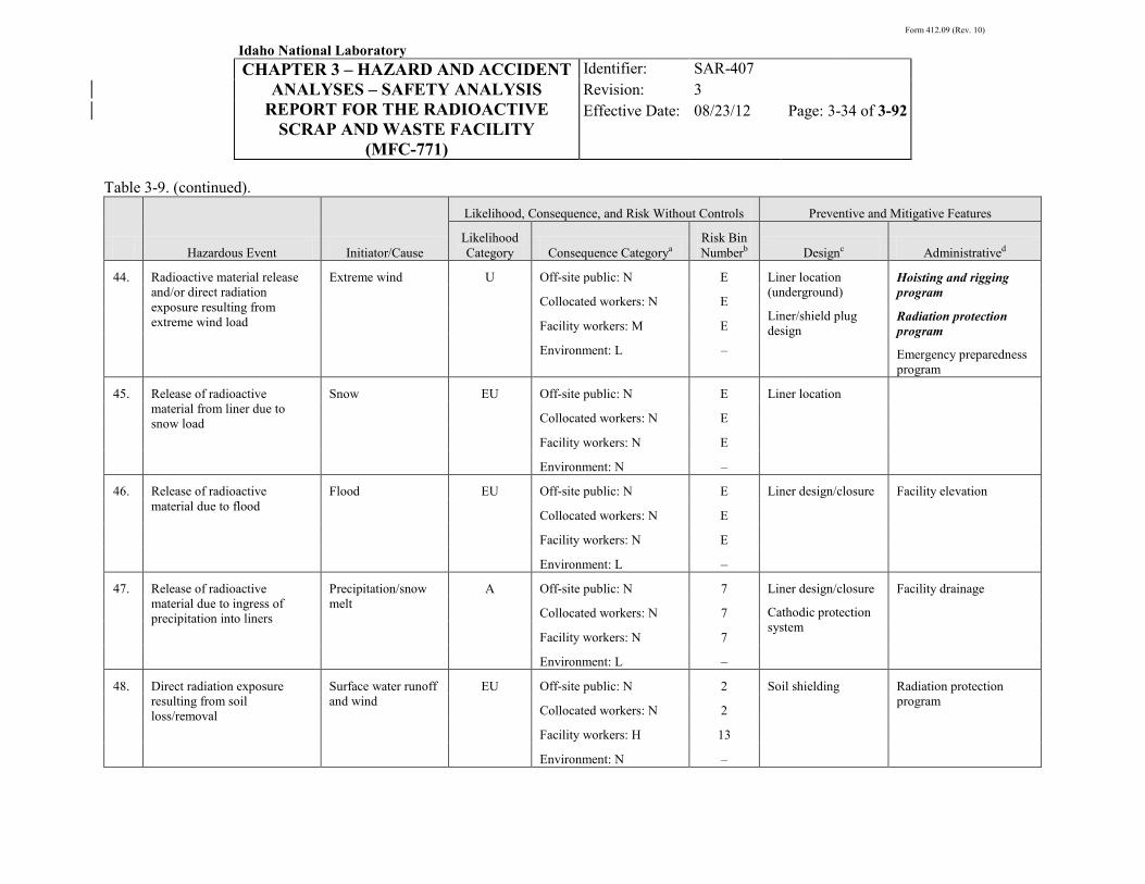
Form 412.09 (Rev. 10)
Idaho National Laboratory
CHAPTER 3 – HAZARD AND ACCIDENT ANALYSES – SAFETY ANALYSIS
REPORT FOR THE RADIOACTIVE SCRAP AND WASTE FACILITY
(MFC-771)
Identifier: Revision: Effective Date:
SAR-407 3 08/23/12 Page: 3-34 of 3-92
Table 3-9. (continued).
Hazardous Event Initiator/Cause
Likelihood, Consequence, and Risk Without Controls Preventive and Mitigative Features
Likelihood Category Consequence Categorya
Risk Bin Numberb Designc Administratived
44. Radioactive material release and/or direct radiation exposure resulting from extreme wind load
Extreme wind U Off-site public: N E Liner location (underground)
Liner/shield plug design
Hoisting and rigging program
Radiation protection program
Emergency preparedness program
Collocated workers: N E
Facility workers: M E
Environment: L –
45. Release of radioactive material from liner due to snow load
Snow EU Off-site public: N E Liner location
Collocated workers: N E
Facility workers: N E
Environment: N –
46. Release of radioactive material due to flood
Flood EU Off-site public: N E Liner design/closure Facility elevation
Collocated workers: N E
Facility workers: N E
Environment: L –
47. Release of radioactive material due to ingress of precipitation into liners
Precipitation/snow melt
A Off-site public: N 7 Liner design/closure
Cathodic protection system
Facility drainage
Collocated workers: N 7
Facility workers: N 7
Environment: L –
48. Direct radiation exposure resulting from soil loss/removal
Surface water runoff and wind
EU Off-site public: N 2 Soil shielding Radiation protection program
Collocated workers: N 2
Facility workers: H 13
Environment: N –

Form 412.09 (Rev. 10)
Idaho National Laboratory
CHAPTER 3 – HAZARD AND ACCIDENT ANALYSES – SAFETY ANALYSIS
REPORT FOR THE RADIOACTIVE SCRAP AND WASTE FACILITY
(MFC-771)
Identifier: Revision: Effective Date:
SAR-407 3 08/23/12 Page: 3-35 of 3-92
Table 3-9. (continued).
Hazardous Event Initiator/Cause
Likelihood, Consequence, and Risk Without Controls Preventive and Mitigative Features
Likelihood Category Consequence Categorya
Risk Bin Numberb Designc Administratived
49. Release of radioactive material due to lightning
Lightning strike EU Off-site public: N 2 Liner location Facility maintenance (weed/brush control)
Fire protection program Collocated workers: N 2
Facility workers: N 2
Environment: N – a. Consequences defined as N = Negligible; L = Low; M = Moderate; H = High.
Likelihood defined as A = Anticipated; U = Unlikely; EU = Extremely Unlikely; BEU = Beyond Extremely Unlikely.
b. Risk bin numbers are highlighted in bold italics if they indicate that safety SSCs, TSRs, and/or safety analysis commitments should be identified to manage the risk (see Figures 3-1, 3-2, and 3-3).
c. SSCs (active or passive) designated as safety-class or safety-significant SSCs are highlighted in bold italics. See Chapter 4, “Safety Structures, Systems, and Components,” for additional information on these safety SSCs.
d. TSR and safety analysis commitment level controls are highlighted in bold italics.
e. Rather than assigning a risk bin number, the risk of NPH events is discussed in Section 3.3.2.3.8 (consistent with the methodology of NS-18104). Binning has been explicitly defined for entries 47, 48, and 49, since the associated initiators (precipitation, runoff/wind, and lighting) do not have PC design criteria.

Form 412.09 (Rev. 10)
Idaho National Laboratory
CHAPTER 3 – HAZARD AND ACCIDENT ANALYSES – SAFETY ANALYSIS
REPORT FOR THE RADIOACTIVE SCRAP AND WASTE FACILITY
(MFC-771)
Identifier: Revision: Effective Date:
SAR-407 3 08/23/12 Page: 3-36 of 3-92
3.3.2.3.1 Fire and Explosion—There are seven events listed in Table 3-9 (hazardous events 1 through 7) that address radioactive material releases due to potential fire and explosion hazards. Potential fire and explosion hazards include transport vehicle fuel ignition, transport vehicle fuel explosion, hydrogen generation and ignition, pyrophoric reactions, and sodium-water reactions.
Generally, there are three factors necessary for combustion: the presence of an oxidizing agent, fuel, and a heat source. The relationship of these factors is commonly denoted as the “fire triangle.” The fire triangle concept, denoted in Figure 3-4 below, illustrates that fuel, an oxidizing agent, and a heat source must all be present together for combustion to occur. If any one of the legs of the triangle is removed, or absent, combustion ceases or does not take place. Potential fuel sources at RSWF include flammable liquids (vehicle fuel), flammable gases (acetylene, hydrogen), and radioactive materials. Some of the latter (e.g., uranium and plutonium) may exhibit pyrophoric characteristics depending upon their chemical and physical form (e.g., hydrides). Others, such as sodium and NaK, are reactive metals that readily react with water and/or air. The most common oxidizer, oxygen, is also available. Normally, an ignition source (e.g., heat, flame, or spark) is needed to ignite a mixture of a fuel and oxidizing agent. However, no external heat source is needed for the combustion of pyrophoric materials in air. These materials are spontaneously ignited by the rapid accumulation of heat evolved from the oxidation reaction between the material and air.
Figure 3-4. Fire triangle.

Form 412.09 (Rev. 10)
Idaho National Laboratory
CHAPTER 3 – HAZARD AND ACCIDENT ANALYSES – SAFETY ANALYSIS
REPORT FOR THE RADIOACTIVE SCRAP AND WASTE FACILITY
(MFC-771)
Identifier: Revision: Effective Date:
SAR-407 3 08/23/12 Page: 3-37 of 3-92
3.3.2.3.1.1 Vehicle Fuel Fire with Casks—This event is HE 1 in Table 3-9. In this event, a fire involving combustible liquids, such as diesel fuel or gasoline, or a conventional fire, is postulated to result in a radioactive material release. The initiator for this event is exposure of the transport vehicle fuel to an ignition source. The ignition source could be from liner welding/cutting activities or a vehicle electrical fire. RSWF is located at a remote distance from other MFC facilities, has no regular vehicle traffic within the facility, and has minimal combustible materials (e.g., vehicle fuel, tires). Also, RSWF and the area immediately surrounding the facility are typically maintained vegetation-free. The RSWF fire hazards analysis (FHA) concluded that the potential hazards from transfer equipment fuel and other combustible materials (vegetation) are of insufficient quantity to threaten the integrity of closed liners due to the incombustible materials of construction and closure covers (steel plate, etc.).12 By inference, such a fire would not pose a threat to the contents of a closed liner.
A fire could also occur during operations involving a transfer cask. The transfer cask scenario could occur during liner loading/unloading, when the cask is sitting on a positioning device, or during transfer of a loaded cask within the facility. The steel positioning device would provide a thermal barrier between a fire and a container of radioactive material during liner loading and unloading, similar to the barrier provided by the bottom door when the cask is closed. Based on the limited quantities of combustible materials, as discussed above, it is unlikely that such a fire would be of sufficient magnitude, intensity and duration to cause significant damage to the positioning device. In addition, the radioactive material containers within the cask are fabricated of materials that are not expected to be significantly degraded by a localized fire of short duration, without taking credit for the cask materials. Such a fire would, however, provide a driving force (heat) that could result in a release of radioactive material from the container/package into the cask, and then outside through small openings, penetrations, etc. in the cask during in-facility transfer, or when the cask is open during liner loading/unloading. This event is considered unlikely, as reflected in Table 3-9.
The consequences of a release of radioactive material from this event are estimated to be negligible to the off-site public and collocated worker, and low to the facility worker and environment. The consequence to the facility worker from a radioactive material release is estimated as low based on a dose consequence evaluation performed to support the accident analysis in Section 3.4.29
The overall risk associated with radioactive material release in this event is acceptable to all receptors based on the risk binning listed in
The dose consequence evaluation was performed to address the open configuration of the cask during liner loading and unloading. The evaluation also conservatively assumed no credit for the shielded transfer cask as a thermal barrier between the fire and the radioactive material, nor for multiple levels of containment for the MAR (e.g., inner and/or outer can or other package, fuel cladding, etc.).
Table 3-9. No additional controls (TSRs or safety SSCs) are required for these dose receptor locations.
A fire that engulfs a cask could also result in the degradation of its shielding capability, if the fire were of prolonged intensity and duration. The consequences of cask shielding degradation of sufficient magnitude with a worst-case loading are estimated to be high for the facility worker, low to the collocated worker, and negligible to the off-site public and environment.30 However, as discussed above, the RSWF FHA concluded that a fuel fire at RSWF would be of a very limited duration due to the inherently small quantity of combustible material in the facility. In addition, the shielding capability of the HFEF-5 and HFEF-14 transfer casks is not expected to be significantly affected in an engulfing 30-minute, 800°C

Form 412.09 (Rev. 10)
Idaho National Laboratory
CHAPTER 3 – HAZARD AND ACCIDENT ANALYSES – SAFETY ANALYSIS
REPORT FOR THE RADIOACTIVE SCRAP AND WASTE FACILITY
(MFC-771)
Identifier: Revision: Effective Date:
SAR-407 3 08/23/12 Page: 3-38 of 3-92
fire.31
3.3.2.3.1.2 Vehicle Fuel Fire with FTCs—This event is HE
Therefore, the direct radiation exposure risk is judged to be adequately represented by the risk identified above for a radioactive material release.
2 in Table 3-9. In this event, a fire involving combustible liquids, such as diesel fuel or gasoline, or a conventional fire, is postulated to result in a radioactive material release. The initiator for this event is exposure of the transport vehicle fuel to an ignition source. The ignition source could be from liner welding/cutting activities or a vehicle electrical fire. RSWF is located at a remote distance from other MFC facilities, has no regular vehicle traffic within the facility, and has minimal combustible materials (e.g., vehicle fuel, tires). Also, RSWF and the area immediately surrounding the facility are typically maintained vegetation-free. The RSWF FHA concluded that the potential hazards from transfer equipment fuel and other combustible materials (vegetation) are of insufficient quantity to threaten the integrity of closed liners due to the incombustible materials of construction and closure covers (steel plate, etc.).12 By inference, such a fire would not pose a threat to the contents of a closed liner. The bounding drop event consequence in Section 3.4.2.1 is the bounding event for an FTC fire and explosion event which is supported by ECAR-1352, “Evaluation of Dose Consequences for Radioactive Scrap and Waste Facility (RSWF) Safety Analysis Report (SAR) Revision,” analysis.
A fire could also occur during operations involving an FTC. The FTCs were designed for retrieval and transport of specific SLSF containers and 24-in. overpack liners. Analysis performed in support of their use concluded that the radioactive material release from a vehicle fire was bounded by analysis performed for retrieval and transport of HFEF-5 containers in ISCs.32
The FTC scenario could occur during liner loading/unloading. Based on the limited quantities of combustible materials, as discussed above, it is unlikely that such a fire would be of sufficient magnitude, intensity, and duration to cause significant damage to the positioning device. In addition, the radioactive material containers within the FTC are fabricated of materials that are not expected to be significantly degraded by a localized fire of short duration, without taking credit for the cask materials. Such a fire would, however, provide a driving force (heat) that could result in a release of radioactive material from the container/package into the FTC, and then outside through small openings, penetrations, etc. in the FTC during in-facility transfer, or when the FTC is open during liner loading/unloading. This event is considered unlikely, as reflected in
To provide a bounding scenario for use of FTCs with non-specific SLSF containers and 24-in. overpack liners within RSWF, the following is assumed: The FTC scenario could occur during liner loading/unloading or overpack liner retrieval and involves the transport vehicle loaded with an FTC containing the same material used in the transfer cask scenario. The FTC scenario could also occur in the RSWF Staging Area and involve transport vehicles (fork lift or transport trailer) with loaded FTCs being prepared/staged prior to transport.
Table 3-9.
The consequences of a release of radioactive material from this event are estimated to be negligible to the off-site public and collocated worker, and low to the facility worker and environment. The consequence to the facility worker from a radioactive material release is estimated as low based on a dose consequence evaluation performed to support the accident analysis in Section 3.4.32,33
29 Radiological
inventories used for the hazard evaluation and accident analysis are discussed in Reference and are based on a liner configuration (blanket subassembly from EBR-II) and pseudo MAR that bounds the maximum possible quantities of fission/activation product radionuclides that could be present in a container containing the maximum actinide content. The dose consequence evaluation was performed to address the open configuration of the FTC during liner loading and unloading. The evaluation also

Form 412.09 (Rev. 10)
Idaho National Laboratory
CHAPTER 3 – HAZARD AND ACCIDENT ANALYSES – SAFETY ANALYSIS
REPORT FOR THE RADIOACTIVE SCRAP AND WASTE FACILITY
(MFC-771)
Identifier: Revision: Effective Date:
SAR-407 3 08/23/12 Page: 3-39 of 3-92
conservatively assumed no credit for the FTC as a thermal barrier between the fire and the radioactive material, nor for multiple levels of containment for the MAR (e.g., inner and/or outer can or other package, fuel cladding, etc.).
The overall risk associated with radioactive material release in this event is acceptable to all receptors based on the risk binning listed in Table 3-9. No additional controls (TSRs or safety SSCs) are required for these dose receptor locations.
A fire that engulfs an FTC could also result in the degradation of its shielding capability if the fire were of prolonged intensity and duration. The consequences of cask shielding degradation of sufficient magnitude with a worst-case loading are estimated to be high for the facility worker, low to the collocated worker, and negligible to the off-site public and environment.34 However, as discussed above, the RSWF FHA concluded that a fuel fire at RSWF would be of a very limited duration due to the inherently small quantity of combustible material in the facility. In addition, the shielding capability of the HFEF-5 and HFEF-14 transfer casks is not expected to be significantly affected in an engulfing 30-minute, 800°C fire.35
3.3.2.3.1.3 Vehicle Fuel Fire with ISCs—This event is HE
A thermal analysis of the FTCs has not been performed, but like the HFEF-5 and HFEF-14 casks, incombustible materials of construction (steel and lead) were used in their construction. Combining this with their overall size (~42-in. diameter × ~15 ft long and weighing ~30,000 lb) and robust design, one can conclude that the shielding capability of the FTCs is not expected to be significantly affected in an engulfing 30-minute, 800°C fire. Therefore, the direct radiation exposure risk is judged to be adequately represented by the risk identified above for a radioactive material release.
3 in Table 3-9. In this event, a fire involving combustible liquids, such as diesel fuel or gasoline, or a conventional fire, is postulated to result in a radioactive material release and or direct radiation exposure. The initiator for this event is exposure of the transport vehicle fuel to an ignition source. The ignition source could be from liner welding/cutting activities or a vehicle electrical fire. RSWF is located at a remote distance from other MFC facilities, has no regular vehicle traffic within the facility, and has minimal combustible materials (e.g., vehicle fuel, tires). Also, RSWF and the area immediately surrounding the facility are typically maintained vegetation-free. The RSWF FHA concluded that the potential hazards from transfer equipment fuel and other combustible materials (vegetation) are of insufficient quantity to threaten the integrity of closed liners due to the incombustible materials of construction and closure covers (steel plate, etc.).12 By inference, such a fire would not pose a threat to the contents of a closed liner. The bounding drop event consequence in Section 3.4.2.1 is the bounding event for an ISC fire and explosion event which is supported by ECAR-1352 analysis
A fire could also occur during operations involving an ISC. The ISC scenario could occur in the RSWF main storage area during liner loading/unloading operations or in the RSWF Staging Area and involves transport vehicles (fork lift or transport trailer) loaded with an ISC containing four HFEF-5 containers. Because of equipment failure or operator error, the diesel fuel from the vehicle fuel tank spills and is ignited, engulfing the ISC. The radioactive material containers within the ISC are fabricated of materials that are not expected to be significantly degraded by a localized fire of short duration without taking credit for the ISC materials. Such a fire would, however, provide a driving force (heat) that could result in a release of radioactive material from the container/package into the ISC, and then outside through small openings, penetrations, etc. in the ISC during in-facility transfer, or when the ISC is open during liner loading/unloading. This event is considered unlikely, as reflected in Table 3-9.
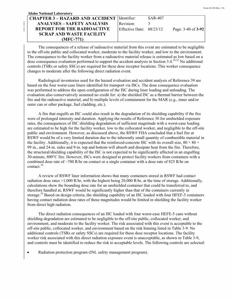
Form 412.09 (Rev. 10)
Idaho National Laboratory
CHAPTER 3 – HAZARD AND ACCIDENT ANALYSES – SAFETY ANALYSIS
REPORT FOR THE RADIOACTIVE SCRAP AND WASTE FACILITY
(MFC-771)
Identifier: Revision: Effective Date:
SAR-407 3 08/23/12 Page: 3-40 of 3-92
The consequences of a release of radioactive material from this event are estimated to be negligible to the off-site public and collocated worker, moderate to the facility worker, and low to the environment. The consequence to the facility worker from a radioactive material release is estimated as low based on a dose consequence evaluation performed to support the accident analysis in Section 3.4.29,32 No additional controls (TSRs or safety SSCs) are required for these dose receptor locations. This worker consequence changes to moderate after the following direct radiation event.
Radiological inventories used for the hazard evaluation and accident analysis of Reference 39 are based on the four worst-case liners identified for transport via ISCs. The dose consequence evaluation was performed to address the open configuration of the ISC during liner loading and unloading. The evaluation also conservatively assumed no credit for: a) the shielded ISC as a thermal barrier between the fire and the radioactive material, and b) multiple levels of containment for the MAR (e.g., inner and/or outer can or other package, fuel cladding, etc.).
A fire that engulfs an ISC could also result in the degradation of its shielding capability if the fire were of prolonged intensity and duration. Applying the results of Reference 30 for unshielded exposure rates, the consequences of ISC shielding degradation of sufficient magnitude with a worst-case loading are estimated to be high for the facility worker, low to the collocated worker, and negligible to the off-site public and environment. However, as discussed above, the RSWF FHA concluded that a fuel fire at RSWF would be of a very limited duration due to the inherently small quantity of combustible material in the facility. Additionally, it is expected that the reinforced-concrete ISC with its overall size, 80 × 80 × 99 in., and 24-in. sides and 9-in. top and bottom will absorb and dissipate heat from the fire. Therefore, the structural/shielding capability of the ISC is not expected to be significantly affected in an engulfing 30-minute, 800°C fire. However, ISCs were designed to protect facility workers from containers with a combined dose rate of ~700 R/hr on contact or a single container with a dose rate of 825 R/hr on contact.36
A review of RSWF liner information shows that many containers stored in RSWF had contact radiation dose rates >1,000 R/hr, with the highest being 20,000 R/hr, at the time of storage. Additionally, calculations show the bounding dose rate for an unshielded container that could be transferred to, and therefore handled at, RSWF would be significantly higher than that of the containers currently in storage.
29 Based on design criteria, the shielding capability of an ISC loaded with four HFEF-5 containers having contact radiation dose rates of these magnitudes would be limited in shielding the facility worker from direct high radiation.
The direct radiation consequences of an ISC loaded with four worst-case HEFE-5 cans without shielding degradation are estimated to be negligible to the off-site public, collocated worker, and environment, and moderate to the facility worker. The risk associated with this event is acceptable to the off-site public, collocated worker, and environment based on the risk binning listed in Table 3-9. No additional controls (TSRs or safety SSCs) are required for these dose receptor locations. The facility worker risk associated with this direct radiation exposure event is unacceptable, as shown in Table 3-9, and controls must be identified to reduce the risk to acceptable levels. The following controls are selected:
• Radiation protection program (INL safety management program).

Form 412.09 (Rev. 10)
Idaho National Laboratory
CHAPTER 3 – HAZARD AND ACCIDENT ANALYSES – SAFETY ANALYSIS
REPORT FOR THE RADIOACTIVE SCRAP AND WASTE FACILITY
(MFC-771)
Identifier: Revision: Effective Date:
SAR-407 3 08/23/12 Page: 3-41 of 3-92
The radiation protection program (e.g., monitoring) is selected as a control for this hazard to reduce exposure to direct radiation through the use of temporary shielding and appropriate radiation monitoring. The overall result is a reduction in the facility worker risk to an acceptable level.
3.3.2.3.1.4 Vehicle Fuel Explosion (Cask)—This event is HE 4 in Table 3-9. In this event, a radioactive material release occurs due to an explosion of the transfer vehicle fuel during liner loading/unloading. The initiator identified for an explosion of the transfer vehicle fuel is a vehicle collision impacting the transfer vehicle fuel tank. Liner loading and unloading operations at RSWF involve a forklift and mobile crane, all of which are parked during liner loading and unloading. In addition, vehicle traffic within RSWF typically only involves vehicles supporting operations and maintenance within the facility, and speeds within the facility are relatively low (10 mph). A vehicle collision that causes an explosive ignition of fuel resulting in radioactive material release is therefore considered extremely unlikely.
The estimated consequences for this event are negligible to the off-site public and collocated worker, low to the environment, and high to the facility worker, taking into account the risk of both radioactive material release and direct radiation exposure in this event (i.e., assumed loss of shielding function, or a portion thereof, of the cask). The risk associated with this event is acceptable for all receptor locations, based on the binning results listed in Table 3-9. No controls (TSRs or safety SSCs) are required.
3.3.2.3.1.5 Vehicle Fuel Explosion (FTC)—This event is HE 5 in Table 3-9. In this event, a radioactive material release occurs due to an explosion of the transfer vehicle fuel during liner loading/unloading operations in the RSWF main storage area or during ISC/FTC staging operations in the RSWF Staging Area. The initiator identified for an explosion of the transfer vehicle fuel is a vehicle collision impacting the transfer vehicle fuel tank. Liner loading and unloading operations at RSWF involve a forklift and mobile crane, and may involve a transfer trailer, all of which are parked during liner loading and unloading. In addition, vehicle traffic within RSWF typically only involves vehicles supporting operations and maintenance within the facility, and speeds within the facility are relatively low (10 mph). A vehicle collision that causes an explosive ignition of fuel resulting in radioactive material release is, therefore, considered extremely unlikely.
A vehicle fuel explosion could occur during operations involving a transfer cask, ISC, or FTC. The vehicle fuel explosion involving the ISC loaded with four HFEF-5 cans is the bounding scenario, and the estimated consequences for this event are negligible to the off-site public and collocated worker, low to the environment, and high to the facility worker, taking into account the risk of both radioactive material release and direct radiation exposure in this event (i.e., assumed loss of shielding function, or a portion thereof, of the ISC). The risk associated with this event is acceptable for all receptor locations based on the binning results listed in Table 3-9. No controls (TSRs or safety SSCs) are required.
3.3.2.3.1.6 Liner Hydrogen Fire/Explosion—This event is HE 6 in Table 3-9. In this event, ignition of an explosive gas mixture (hydrogen-oxygen) within a liner results in the release of radioactive material. The overall sequence of events is generation and accumulation of a flammable gas mixture inside a liner, ignition of the gas mixture, and damage to the liner and containers sufficient to result in the release of radioactive material.
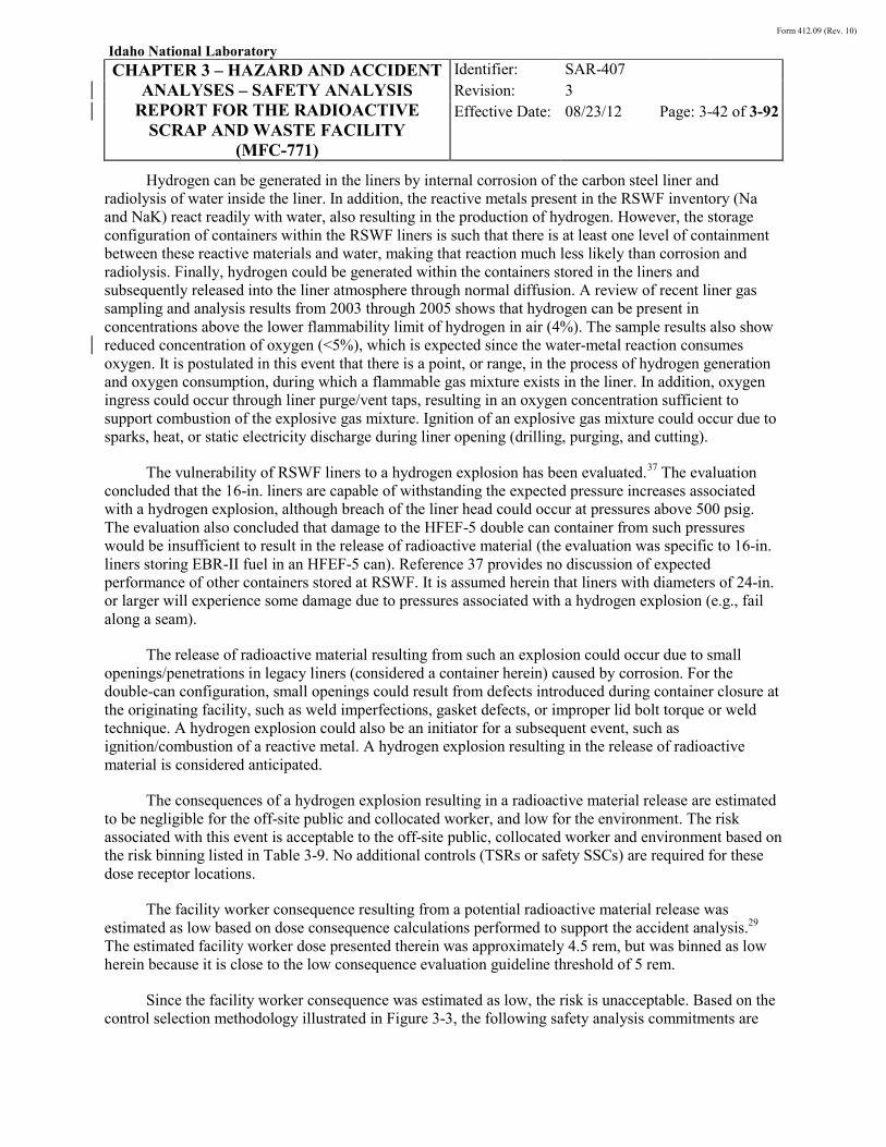
Form 412.09 (Rev. 10)
Idaho National Laboratory
CHAPTER 3 – HAZARD AND ACCIDENT ANALYSES – SAFETY ANALYSIS
REPORT FOR THE RADIOACTIVE SCRAP AND WASTE FACILITY
(MFC-771)
Identifier: Revision: Effective Date:
SAR-407 3 08/23/12 Page: 3-42 of 3-92
Hydrogen can be generated in the liners by internal corrosion of the carbon steel liner and radiolysis of water inside the liner. In addition, the reactive metals present in the RSWF inventory (Na and NaK) react readily with water, also resulting in the production of hydrogen. However, the storage configuration of containers within the RSWF liners is such that there is at least one level of containment between these reactive materials and water, making that reaction much less likely than corrosion and radiolysis. Finally, hydrogen could be generated within the containers stored in the liners and subsequently released into the liner atmosphere through normal diffusion. A review of recent liner gas sampling and analysis results from 2003 through 2005 shows that hydrogen can be present in concentrations above the lower flammability limit of hydrogen in air (4%). The sample results also show reduced concentration of oxygen (<5%), which is expected since the water-metal reaction consumes oxygen. It is postulated in this event that there is a point, or range, in the process of hydrogen generation and oxygen consumption, during which a flammable gas mixture exists in the liner. In addition, oxygen ingress could occur through liner purge/vent taps, resulting in an oxygen concentration sufficient to support combustion of the explosive gas mixture. Ignition of an explosive gas mixture could occur due to sparks, heat, or static electricity discharge during liner opening (drilling, purging, and cutting).
The vulnerability of RSWF liners to a hydrogen explosion has been evaluated.37
37
The evaluation concluded that the 16-in. liners are capable of withstanding the expected pressure increases associated with a hydrogen explosion, although breach of the liner head could occur at pressures above 500 psig. The evaluation also concluded that damage to the HFEF-5 double can container from such pressures would be insufficient to result in the release of radioactive material (the evaluation was specific to 16-in. liners storing EBR-II fuel in an HFEF-5 can). Reference provides no discussion of expected performance of other containers stored at RSWF. It is assumed herein that liners with diameters of 24-in. or larger will experience some damage due to pressures associated with a hydrogen explosion (e.g., fail along a seam).
The release of radioactive material resulting from such an explosion could occur due to small openings/penetrations in legacy liners (considered a container herein) caused by corrosion. For the double-can configuration, small openings could result from defects introduced during container closure at the originating facility, such as weld imperfections, gasket defects, or improper lid bolt torque or weld technique. A hydrogen explosion could also be an initiator for a subsequent event, such as ignition/combustion of a reactive metal. A hydrogen explosion resulting in the release of radioactive material is considered anticipated.
The consequences of a hydrogen explosion resulting in a radioactive material release are estimated to be negligible for the off-site public and collocated worker, and low for the environment. The risk associated with this event is acceptable to the off-site public, collocated worker and environment based on the risk binning listed in Table 3-9. No additional controls (TSRs or safety SSCs) are required for these dose receptor locations.
The facility worker consequence resulting from a potential radioactive material release was estimated as low based on dose consequence calculations performed to support the accident analysis.29 The estimated facility worker dose presented therein was approximately 4.5 rem, but was binned as low herein because it is close to the low consequence evaluation guideline threshold of 5 rem.
Since the facility worker consequence was estimated as low, the risk is unacceptable. Based on the control selection methodology illustrated in Figure 3-3, the following safety analysis commitments are

Form 412.09 (Rev. 10)
Idaho National Laboratory
CHAPTER 3 – HAZARD AND ACCIDENT ANALYSES – SAFETY ANALYSIS
REPORT FOR THE RADIOACTIVE SCRAP AND WASTE FACILITY
(MFC-771)
Identifier: Revision: Effective Date:
SAR-407 3 08/23/12 Page: 3-43 of 3-92
identified to mitigate facility worker risk from a potential radioactive material release initiated by combustion of a flammable gas mixture in a liner:
• Remote liner drilling (safety analysis commitment)
• Liner purging/venting (safety analysis commitment).
The remote liner drilling commitment reduces the consequences of a radioactive material release to the facility worker by removing the facility worker from the potential hazard during initial opening (drilling) of a closed liner. Drilling introduces an ignition source into a closed system (liner) with a potentially explosive gas atmosphere. Remote liner drilling involves the use of a drilling apparatus designed to be operated several feet from the liner. The remote drilling system is used to install vent/purge taps into closed liners.
The liner purging/venting commitment reduces the likelihood of a hydrogen explosion/fire by purging a liner with an inert gas, or by passively venting a liner, after vent/purge tap(s) have been installed using the remote liner drilling system, but prior to opening/cutting the liner. When liners are passively vented, sampling of the liner atmosphere is performed to confirm the absence of a potentially flammable gas mixture prior to cutting/opening. The remote liner drilling and liner purging/venting commitments apply to those liners that have welded closure covers. The combined effect of these commitments is a reduction in the facility worker risk to an acceptable level.
3.3.2.3.1.7 Container Fire/Deflagration—This event is HE 7 in Table 3-9. This event addresses a container fire/deflagration due to the presence of pyrophoric material, flammable/explosive gases, or reactive materials. Metallic uranium in various forms, including clad fuel elements, fuel chips, and cladding scrap, has been stored at RSWF. Uranium metal can react with water to form hydrogen (the hazard associated with hydrogen is addressed in HE 6 above). The hydrogen may then react with the uranium metal to form uranium hydride (UH3). The hydride may in turn react with oxygen in air to form stable uranium oxide (UO2) and hydrogen (H2).38,39
38
Uranium hydride is a pyrophoric substance and will readily react in the presence of oxygen/air. Pyrophoric forms of plutonium could also result from similar reactions. The presence and oxidation (fire) of small quantities of pyrophoric materials has been observed in the FCF air cell when removing EBR-II fuel elements from an HFEF-5 can that had been stored at RSWF for several years. The FCF incident (experience) confirms the presence of pyrophoric material at RSWF, either as a reaction product generated in a container during passive storage, or as a potential legacy material. Therefore, it is a hazard that must be addressed.
In addition to pyrophoric materials, the generation and accumulation of hydrogen within a container could result in a container fire (deflagration). A container deflagration due to hydrogen or other flammable gas mixture requires the presence of oxygen (assumed) and an ignition source. Mechanisms by which a flammable gas mixture might accumulate within the closed containers at RSWF are limited due to the absence of volatile organic compounds in the containers and the loading of containers in hot cells with inert atmospheres. However, radiolysis of hydrogenous material within the container could result in hydrogen generation. Once generated, deflagration of a flammable gas mixture within a container requires an ignition source. The presence of ignition sources at RSWF is very limited due to the nature of the operations performed at the facility, which excludes drilling, opening, or repackaging of containers. In addition, the double (i.e., nested) can configuration of most containers would limit potential lid loss, even

Form 412.09 (Rev. 10)
Idaho National Laboratory
CHAPTER 3 – HAZARD AND ACCIDENT ANALYSES – SAFETY ANALYSIS
REPORT FOR THE RADIOACTIVE SCRAP AND WASTE FACILITY
(MFC-771)
Identifier: Revision: Effective Date:
SAR-407 3 08/23/12 Page: 3-44 of 3-92
if hydrogen combustion occurs within the container. Therefore, the overall likelihood of a container deflagration at RSWF is judged to be extremely unlikely.
A pyrophoric material fire in a storage liner requires the presence of pyrophoric material, the presence of oxygen, and a pathway for the oxygen to contact the pyrophoric material. Air/oxygen ingress occurs when the liners are opened to remove the container. The storage configuration of packages within the RSWF liners is such that there is at least one level of containment that serves as a barrier between the radioactive material and the liner atmosphere. Since containers are not opened at RSWF, failure of the containers while stored in the liner (e.g., corrosion of legacy liners, failure of gaskets/welds in double cans) is necessary in order to create a pathway for oxygen to contact and react with pyrophoric materials. Because of this sequence, the pyrophoric event is also considered extremely unlikely.
Reactive materials in the RSWF inventory include NaK. As discussed in Section 3.3.2.1.3, the unique hazards associated with NaK include a thermite-type reaction (mixing of NaK and potassium superoxide) and an explosion hazard (mixing of NaK and/or superoxide with liquid hydrocarbons). The NaK-superoxide-liquid hydrocarbon mixing is dismissed from further consideration in this analysis because free liquids were historically precluded from storage at RSWF. In addition, the storage records associated with the liners containing NaK include no indication of the presence of such liquid hydrocarbons.
A thermitic reaction that results in the release of radioactive material from a liner is considered extremely unlikely. As described previously, the storage configuration of packages within the RSWF liners is such that there is at least one barrier between the NaK and the liner atmosphere. Since containers are not opened at RSWF, failure of the containers at time of placement (e.g., container drop) or while stored in the liner (e.g., corrosion of legacy liners, failure of gaskets/welds in double cans) is necessary in order to create a pathway for oxygen to react with the NaK and form oxides, including potassium superoxide. The quantity of any oxides formed is expected to be small due to the limited amount of oxygen available to react with the NaK in a closed liner. If an oxide crust were to form on the surface of the NaK, the thermitic reaction occurs only if the oxide crust is permeated and the potassium superoxide is allowed to mix with the potassium in the NaK. Such mixing is extremely unlikely given the passive storage configuration of the containers at RSWF.
The consequences of a fire, deflagration, or thermitic-type reaction within a container or liner are considered negligible to the off-site public and collocated worker, and low for the facility worker and the environment. The risk associated with this event is acceptable to all receptors based on the risk binning listed in Table 3-9. No additional controls (TSRs or safety SSCs) are required for these dose receptor locations and the environment.
3.3.2.3.2 Radioactive Material Release—There are 13 potential HEs that could result in a radioactive material release during facility operations at RSWF. Facility operations include transfer and handling of shielded casks, FTCs, and ISCs containing radioactive material; liner drilling, venting, sampling, purging and/or opening; container handling; liner handling; and, soil excavation. This section describes HEs associated with these facility operations.
3.3.2.3.2.1 Liner Opening Release—This event is HE 8 in Table 3-9. This event postulates the presence of uncontained radioactive material inside a liner. A radioactive material release is assumed to occur when a liner is opened, such as during drilling in preparation for liner opening or during liner cutting for container retrieval. The presence of uncontained radioactive material inside a
Form 412.09 (Rev. 10)
Idaho National Laboratory
CHAPTER 3 – HAZARD AND ACCIDENT ANALYSES – SAFETY ANALYSIS
REPORT FOR THE RADIOACTIVE SCRAP AND WASTE FACILITY
(MFC-771)
Identifier: Revision: Effective Date:
SAR-407 3 08/23/12 Page: 3-45 of 3-92
liner could occur as a result of an externally-contaminated container being placed inside a liner, or from container defects, such as small openings, gaps or other penetrations through which radioactive material could migrate while the container is stored inside the liner.
The placement of an externally-contaminated container into a clean liner is not expected based on radiological controls at the facilities in which containers are loaded and prepared for transfer to RSWF. Contamination control practices at the originating facility include surveys to ensure that the exterior surface of outer containers is free of radiological contamination prior to transfer. These same kinds of practices at RSWF also ensure the absence of radiological contamination on the external surface of containers prior to container transfer into a liner. In the case of legacy liners, radiological surveys of the retrieved liners and the soil from which they were retrieved, performed at the time of relocation, found no evidence of radiological contamination (based on discussion with operations personnel involved with the relocation effort).
Small openings or other penetrations could result from possible ongoing corrosion of legacy liners (considered a container herein) due to the presence of moist soil adhered to the lower portion of the liners when they were retrieved for relocation to overpack liners. For double can containers (post-1978 standard container), small openings could result from defects introduced during container closure at the originating facility, such as weld imperfections, gasket defects, or improper lid bolt torque or weld technique. The presence of argon gas as indicated by a recent liner sampling activity indicates the possibility of such imperfections since inner cans are loaded in an argon atmosphere hot cell, closed, and then transferred to an air cell for placement inside an outer can. In addition to container defects, fuel cladding breaches have been identified on occasion upon opening a fuel container that had been in storage at RSWF for several years.
Such defects and failures could provide a pathway for potential radioactive material migration due to ambient thermal and pressure effects; however, such migration is expected to be minimal, except for fission product gases which will diffuse through any openings. The presence of fission product gases (Kr-85 in particular) is of concern primarily in those liners (~20) that contain EBR-II driver fuel elements. The overall likelihood of this event is considered anticipated.
The consequences of a radioactive material release during liner opening are estimated to be negligible for all dose receptor locations. The risk associated with this event is acceptable to off-site public, collocated worker, facility worker, and environment based on the risk binning listed in Table 3-9. No additional controls (TSRs or safety SSCs) are required for these dose receptor locations.
3.3.2.3.2.2 Liner Drop/Failure During Lifting or Handling—This event is HE 9 in Table 3-9. In this event, a radioactive material release occurs from the drop of a liner containing radioactive material. The liner configurations considered in this event include the 24-in. overpack liners containing a 16-in. legacy liner, and a 16-in. legacy liner containing a double can. In most cases, legacy liners containing radioactive material stored prior to 1978 serve as the primary containment for the radioactive materials inside (i.e., no credit is taken for the integrity of the pre-1978 paint cans). However, in some configurations, the legacy liners contain radioactive material in a double can (HFEF-5 can), which may be retrieved for transfer within or from the RSWF. The configuration of the legacy liner in an overpack liner is shown in Figure 2-6 in Chapter 2. Overpack liners require retrieval, lifting, and handling for transfer to a treatment facility. Lifting and handling of liners is performed using a crane and appropriate hoisting and rigging equipment. The initiator for this event could be failure of the load

Form 412.09 (Rev. 10)
Idaho National Laboratory
CHAPTER 3 – HAZARD AND ACCIDENT ANALYSES – SAFETY ANALYSIS
REPORT FOR THE RADIOACTIVE SCRAP AND WASTE FACILITY
(MFC-771)
Identifier: Revision: Effective Date:
SAR-407 3 08/23/12 Page: 3-46 of 3-92
linkage during lifting and handling of a loaded liner, or failure of the liner due to loss of integrity (external and/or internal corrosion, excessive force on liner during retrieval from soil). Load linkage failure could result from inadequate lifting lug welds or failure of hoisting and rigging equipment. The drop or failure of the liner results in a release of radioactive material upon impact. The likelihood of this event is conservatively considered anticipated.
The estimated consequences of this event are negligible for the off-site public and collocated worker, and low for the environment. The risk associated with this event is acceptable to the off-site public, collocated worker, and environment based on the risk binning listed in Table 3-9. No additional controls (TSRs or safety SSCs) are required for these locations.
The facility worker consequence was estimated as low based on dose consequence calculations performed to support the accident analysis.40
Table 3-9 The facility worker risk is unacceptable based on the risk
binning in . In accordance with the control selection methodology illustrated in Figure 3-3, the following safety analysis commitments are identified to mitigate facility worker risk from a potential liner drop:
• Hoisting and rigging program (INL safety management program)
• Radiation protection program (INL safety management program).
The hoisting and rigging program requirements (e.g., inspection, load-tested lifting equipment; operator training) and the radiation protection program (e.g., monitoring) serve to reduce the facility worker risk to an acceptable level.
3.3.2.3.2.3 SNF/Accountable Material Container Drop Due to Load Linkage Failure—This event is HE 10 in Table 3-9. A radioactive material release could occur due to a container handling mishap during liner loading or unloading. In this event, a container drop, with container failure upon impact, results in the release of radioactive material. Transfer and handling of containers is performed using a crane and appropriate hoisting and rigging equipment. The initiator for this event is a load linkage failure when the container is being transferred between a shielded cask and the liner.
The containers handled at RSWF consist of a dual, nested, sealed container configuration (or other packaging configuration that provides at least double containment of radioactive material). Drop tests of HFEF-5 and TRU-RH waste container configurations (inner/outer can) found that the outer container retained its integrity, based on a leak test, following a drop from several feet under the conditions of the test.41,42
The estimated consequences for this event are negligible for the off-site public and collocated worker, and low to the environment. The risk associated with this event is acceptable to the off-site public, collocated worker, and environment based on the risk binning listed in
The results show that an inner/outer can configuration provides a good barrier to potential release of radioactive material in the event of a drop. However, the drop tests do not envelope all current conditions (e.g., drop height), nor can the integrity of the containers be inspected prior to handling. A hoisting and rigging mishap resulting in the failure of the inner and outer can, or other double containment configuration, and a release of radioactive material, is considered unlikely.
Table 3-9. No additional controls (TSRs or safety SSCs) are required for these locations.

Form 412.09 (Rev. 10)
Idaho National Laboratory
CHAPTER 3 – HAZARD AND ACCIDENT ANALYSES – SAFETY ANALYSIS
REPORT FOR THE RADIOACTIVE SCRAP AND WASTE FACILITY
(MFC-771)
Identifier: Revision: Effective Date:
SAR-407 3 08/23/12 Page: 3-47 of 3-92
The facility worker consequence was estimated as low, based on waste container dose consequence calculations performed to support the accident analysis,40 and increased to moderate with consideration given to the total fissionable material mass allowed in a 4-in. can per the RSWF criticality safety evaluation (CSE) (see Section 3.4.2.1 herein). The facility worker risk is unacceptable based on the risk binning in Table 3-9. Controls must be identified to mitigate facility worker risk from the potential release from an accountable material container drop. The following controls are selected:
• Container handling limit (TSR-level SAC)
• Hoisting and rigging program (INL safety management program)
• Radiation protection program (INL safety management program).
The container handling limit serves to protect the bounds of analysis for the container drop accidents by limiting the number of containers handled to one at any given time. The hoisting and rigging program requirements (e.g., inspection, load-tested lifting equipment; operator training) and the radiation protection program (e.g., monitoring) serve to reduce facility worker risk to an acceptable level.
3.3.2.3.2.4 Waste Container Drop Due to Load Linkage Failure—This event is HE 11 in Table 3-9. A radioactive material release could occur due to a container handling mishap during liner loading or unloading. In this event, a container drop, with container failure upon impact, results in the release of radioactive material. Transfer and handling of containers is performed using a crane and appropriate hoisting and rigging equipment. The initiator for this event is a load linkage failure when the container is being transferred between a shielded cask or shielded FTC and the liner or between an ISC and the liner.
Drop tests of HFEF-5 and TRU-RH waste container configurations (inner/outer can) found that the outer container retained its integrity, based on a leak test, following a drop from several feet under the conditions of the test.41,42 The results show that an inner/outer can configuration provides a good barrier to potential release of radioactive material in the event of a drop. However, the drop tests do not envelope all current conditions (e.g., drop height), nor can the integrity of the containers be inspected prior to handling. A hoisting and rigging mishap resulting in the failure of the inner and outer can, or other double containment configuration, and a release of radioactive material, is considered unlikely.
The estimated consequences for this event are negligible for the off-site public and collocated worker, and low for the facility worker and to the environment.32,40 The risk associated with this event is acceptable to off-site public, collocated worker, facility worker, and environment based on the risk binning listed in Table 3-9. No additional controls (TSRs or safety SSCs) are required for these dose receptor locations.
Form 412.09 (Rev. 10)
Idaho National Laboratory
CHAPTER 3 – HAZARD AND ACCIDENT ANALYSES – SAFETY ANALYSIS
REPORT FOR THE RADIOACTIVE SCRAP AND WASTE FACILITY
(MFC-771)
Identifier: Revision: Effective Date:
SAR-407 3 08/23/12 Page: 3-48 of 3-92
3.3.2.3.2.5 Multiple Waste Container Breach Due to Load Linkage Failure—This event is HE 12 in Table 3-9. A radioactive material release from multiple waste container breaches could occur due to a container handling mishap during liner loading or unloading. In this event a waste container drop onto another waste container, such as in an open-in-ground storage liner or an open ISC, may result in the breach of multiple containers. Transfer and handling of containers is performed using a crane and appropriate hoisting and rigging equipment. The initiator for this event is a load linkage failure when the container is being transferred between a shielded cask or shielded FTC and the liner or between an ISC and the liner. A crane failure or tipping of a crane could also result in multiple containers being breached.
The containers handled at RSWF consist of a dual, nested, sealed container configuration (or other packaging configuration that provides at least double containment of radioactive material). Drop tests of HFEF-5 and TRU-RH waste container configurations (inner/outer can) found that the outer container retained its integrity, based on a leak test, following a drop from several feet under the conditions of the test.41,42 The results show that an inner/outer can configuration provides a good barrier to potential release of radioactive material in the event of a drop. However, the drop tests do not envelope all current conditions (e.g., drop height), nor can the integrity of the containers be inspected prior to handling. A hoisting and rigging mishap resulting in the failure of the inner and outer can, or other double containment configuration, and a release of radioactive material, is considered unlikely. However, given the design of the ISC (each container loaded vertically in 1/4-in.-thick steel pipe surrounded by concrete)36 and the robust nature of the HFEF-5 canisters, it is extremely unlikely that a dropped container would result in the breach of the three loaded containers in addition to the dropped container.
These multiple container breach scenarios are bound by a single HFEF-5 waste container being dropped on an open ISC loaded with three HFEF-5 waste containers and breaching all four containers.32 The estimated consequences for this event are negligible for the off-site public and collocated worker, moderate for the facility worker, and low to the environment. The risk associated with this event is acceptable to off-site public, collocated worker, facility worker, and environment based on the risk binning listed in Table 3-9. No additional controls (TSRs or safety SSCs) are required for these dose receptor locations.
3.3.2.3.2.6 Liner/Container Breach Due to Heavy Object Impact or Load—This event is HE 13 in Table 3-9. In this event, a radioactive material release occurs due to the breach of a liner resulting from the impact of a heavy object (e.g., cask drop) on the top of the liner. The force of the impact causes the shield plug assembly to fall onto the container/contents stored within the liner. The resulting impact of the cover plate/shield plug assembly on the container stored in the liner could result in a small release of radioactive material if any breach of the container(s) occurred.
In addition to a heavy object impact, a liner/container breach could occur if the loads imposed on the liners during forklift/cask or crane operations exceed the structural capacity of the liners. As discussed in Section 2.4.4.5, an analysis of the structural capability of the 16-, 24-, 26-, and 30-in. liners to withstand static and dynamic loads from soil and heavy equipment has been performed.43
The estimated consequences of this event are negligible for the off-site public and collocated worker, and low for the environment. The risk associated with this event is acceptable to the off-site
The drop or failure onto the liner results in a release of radioactive material upon impact. The likelihood of this event is conservatively considered anticipated.

Form 412.09 (Rev. 10)
Idaho National Laboratory
CHAPTER 3 – HAZARD AND ACCIDENT ANALYSES – SAFETY ANALYSIS
REPORT FOR THE RADIOACTIVE SCRAP AND WASTE FACILITY
(MFC-771)
Identifier: Revision: Effective Date:
SAR-407 3 08/23/12 Page: 3-49 of 3-92
public, collocated worker, and environment based on the risk binning listed in Table 3-9. No additional controls (TSRs or safety SSCs) are required for these locations.
The facility worker consequence was estimated as low based on dose consequence calculations performed to support the accident analysis. The facility worker risk is unacceptable based on the risk binning in Table 3-9. In accordance with the control selection methodology illustrated in Figure 3-3, the following safety analysis commitments are identified to mitigate facility worker risk from a potential liner drop:
• Radiation protection program (INL safety management program)
• Procedural requirement to evaluate equipment being utilized near liners (safety analysis commitment).
The radiation protection program (e.g., monitoring) serves to reduce the facility worker risk to an acceptable level. The procedural requirement to evaluate equipment being utilized near liners is completed in RSWF ECARs such as ECAR-1827, “RSWF Equipment Loading Adjacent to Liners.”43 This requirement serves to reduce facility worker risk to an acceptable level.
3.3.2.3.2.7 48-in. and/or 60-in. Liner/Container Heavy Load Requirement—This event is HE 14 in Table 3-9. In this event, a radioactive material release occurs due to loads imposed on the liners during forklift/cask or crane operations exceed the structural capacity of the liners. As discussed in Section 2.4.4.5, an analysis of the structural capability of the 48- and 60-in. liners to withstand static and dynamic loads from soil and heavy equipment has not been performed (ECAR-1827). The failure of a 48-in. and/or 60-in. liner results in a release of radioactive material. The likelihood of this event is conservatively considered anticipated.
The estimated consequences of this event are negligible for the off-site public and collocated worker, and low for the environment. The risk associated with this event is acceptable to the off-site public, collocated worker, and environment based on the risk binning listed in Table 3-9. No additional controls (TSRs or safety SSCs) are required for these locations.
The facility worker consequence was estimated as low based on dose consequence calculations performed to support the accident analysis. The facility worker risk is unacceptable based on the risk binning in Table 3-9. In accordance with the control selection methodology illustrated in Figure 3-3, the following safety analysis commitments are identified to mitigate facility worker risk from a heavy load event:
• Radiation protection program (INL safety management program)
• Procedural requirement to protect unanalyzed liners (safety analysis commitment).
The radiation protection program (e.g., monitoring) serves to reduce the facility worker risk to an acceptable level. The procedural requirement is a safety analysis commitment serving to manage facility worker risk by keeping heavy equipment away from the RSWF unanalyzed liners as detailed in an RSWF procedure. This procedure requirement serves to reduce facility worker risk to an acceptable level.

Form 412.09 (Rev. 10)
Idaho National Laboratory
CHAPTER 3 – HAZARD AND ACCIDENT ANALYSES – SAFETY ANALYSIS
REPORT FOR THE RADIOACTIVE SCRAP AND WASTE FACILITY
(MFC-771)
Identifier: Revision: Effective Date:
SAR-407 3 08/23/12 Page: 3-50 of 3-92
3.3.2.3.2.8 Cask Drop During In-Facility Container Movement—This event is HE 15 in Table 3-9. This event addresses the handling and transfer of radioactive material containers within RSWF using a shielded transfer cask (HFEF-5 and HFEF-14 casks), as discussed in Chapter 2. A forklift/cask adapter is used to move the shielded transfer casks within the RSWF. Equipment failure or operator error could result in the drop of a transfer cask. The subsequent impact of the cask with the ground or other surface (e.g., liner or asphalt roadway) could damage the containers held within, resulting in the release of radioactive material.
A cask drop could occur due to tipping of a properly configured forklift/cask driven over uneven surfaces. At RSWF, there are minor variations in the surface (e.g., minor sloping of soil from the center of the liner array to the outer edge, and slight elevation of the concrete pathway above the soil), but the overall topography within the facility is essentially level. This includes the asphalt roadway, the soil within the liner array, and the concrete pathways between three rows of liners. A cask drop could also occur if the cask adapter was not connected to the forklift, or if the cask were not connected to the adapter. This could result from equipment failure (e.g., shackle, chain, adapter pins) or operator error (e.g., failure to connect the adapter to the forklift, or failure to properly, or fully, engage the cask with the adapter pins). A subsequent radioactive material release could occur from a cask if the force of the impact from the drop resulted in significant damage to the cask and/or container held inside. The surfaces on which a cask could be dropped within RSWF include the asphalt road, dirt, or a liner.
The expected performance of the HFEF-5 and HFEF-14 casks under postulated drop scenarios onto a concrete surface has been evaluated.44,45
40
The evaluations considered cask drops from a height of 6 ft with low temperature conditions (i.e., −40°F), while loaded with a generic outer can (representative of the double can configuration). The evaluation concluded that the outer steel shell, lead shielding, and doors of the casks experience varying degrees of damage, but will typically contain their payload. The evaluation also showed that an outer can may experience deformation and strain, but not to a degree that a breach occurs. Catastrophic failure of the cask is not expected for any of the drop impacts evaluated. However, the tines on the forklift used to move casks within RSWF can be raised approximately 11 ft above the ground. In conjunction with the cask adapter, the maximum height that the casks could be lifted above the ground is approximately 8.5 ft for the HFEF-5 cask and 5.5 ft for the HFEF-14 cask. The maximum drop height for the HFEF-5 cask is greater than the analyzed cask drop height, and is assumed herein to result in sufficient damage such that a radioactive material release occurs. Therefore, a cask drop resulting in a release of radioactive material is considered unlikely.
The estimated consequences of a dropped cask during in-facility container movements are considered negligible to the off-site public and collocated worker, and low to the environment. The risk associated with this event is acceptable to the off-site public, collocated worker, and environment based on the risk binning in Table 3-9. Additional controls (TSRs or safety SSCs) are not required for these dose receptors.
Form 412.09 (Rev. 10)
Idaho National Laboratory
CHAPTER 3 – HAZARD AND ACCIDENT ANALYSES – SAFETY ANALYSIS
REPORT FOR THE RADIOACTIVE SCRAP AND WASTE FACILITY
(MFC-771)
Identifier: Revision: Effective Date:
SAR-407 3 08/23/12 Page: 3-51 of 3-92
The facility worker consequence is estimated as low, based on waste container dose consequence calculations performed to support the accident analysis,40 and increased to moderate with consideration given to the total fissionable material mass allowed in a 4-in. can per the RSWF CSE (see Section 3.4.2.1 herein). The facility worker risk is unacceptable based on the risk binning in Table 3-9. Controls must be identified to reduce the facility worker risk to an acceptable level. The following controls are selected:
• Shielded transfer cask (HFEF-5 and HFEF-14 casks) (safety-significant SSC)
• RSWF in-facility movements (TSR-level SAC)
• Radiation protection program (INL safety management program).
The selection of the shielded transfer cask as a safety-significant SSC serves to prevent the release of the container from the cask. The RSWF in-facility container movement TSR identifies the parameters and conditions that must be met for transfer of radioactive material. The radiation protection program is also selected because of the direct radiation hazard that exists in the absence of shielding. The radiation protection program ensures that consequences from a cask drop are reduced to acceptable levels through monitoring and other controls (e.g., distance). The combined effect of these controls is to reduce the risk to an acceptable level for the facility worker.
3.3.2.3.2.9 FTC Drop During In-Facility Container Movement—This event is HE 16 in Table 3-9. This event addresses the handling and transfer of radioactive material waste containers within RSWF using a shielded FTC, as discussed in Chapter 2. A forklift/receiving station is used to move the shielded FTC within RSWF. Equipment failure or operator error could result in the drop of an FTC. The subsequent impact of the FTC with the ground or other surface (e.g., liner or asphalt roadway) could damage the container held within, resulting in the release of radioactive material.
A drop analysis of the shielded FTC has not been performed; however, catastrophic failure of the FTC is not expected from drops at heights similar to those used in the HFEF-5 and HFEF-14 cask analysis. Like the HFEF-5 and HFEF-14 <6 ft cask drops, it is assumed that a drop of the FTC results in sufficient damage (FTC and container) and subsequent release of radioactive material. An FTC drop resulting in a release of radioactive material is considered anticipated.
Results of the consequence analysis performed in support of retrieving and transporting specific large liners (24-in.) and SLSF containers31 is bound by the dose consequence analysis performed in support of Table 3-9, HE 15.40 To provide a bounding scenario for FTCs loaded with non-specific large liners, SLSF containers, or other waste containers, consequence analysis was performed using the pseudo MAR of Reference 40. Consideration was given to the total fissile material mass allowed in a 4-in. fuel can per the RSWF CSE (see Section 3.4.2.1herein) as was done for HE 15.32
The estimated consequences of a dropped FTC during in-facility container movements are considered negligible to the off-site public and collocated worker, and low to the environment. The risk associated with this event is acceptable to the off-site public, collocated worker, and environment based on the risk binning in Table 3-9. Additional controls (TSRs or safety SSCs) are not required for these dose receptors.

Form 412.09 (Rev. 10)
Idaho National Laboratory
CHAPTER 3 – HAZARD AND ACCIDENT ANALYSES – SAFETY ANALYSIS
REPORT FOR THE RADIOACTIVE SCRAP AND WASTE FACILITY
(MFC-771)
Identifier: Revision: Effective Date:
SAR-407 3 08/23/12 Page: 3-52 of 3-92
The facility worker consequence is estimated as low based on container dose consequence calculations performed to support the accident analysis,40 and increased to moderate with consideration given to the total fissionable material mass allowed in a 4-in. can per the RSWF CSE (see Section 3.4.2.1 herein). The facility worker risk is unacceptable based on the risk binning in Table 3-9. Controls must be identified to reduce the facility worker risk to an acceptable level. The following controls are selected:
• RSWF in-facility movements (TSR-level SAC)
• Radiation protection program (INL safety management program).
The radiation protection program is also selected because of the direct radiation hazard that exists in the absence of shielding. The radiation protection program (monitoring) ensures that consequences from a FTC drop are reduced to acceptable levels through monitoring and other controls (e.g., distance). The combined effect of these controls is to reduce the risk to an acceptable level for the facility worker.
3.3.2.3.2.10 ISC Drop During In-Facility Container Movement—This event is HE 17 in Table 3-9. This event addresses the handling and transfer of radioactive material containers within RSWF using an ISC as discussed in Chapter 2. A forklift or mobile crane is used to place the ISC on the ground or on the trailer, as appropriate, for movement within RSWF. Equipment failure or operator error could result in the drop of an ISC. A crane failure or tipping of a crane could also result in multiple containers being breached. The subsequent impact of the ISC with the ground or other surface (e.g., liner or asphalt roadway) could damage the containers held within, resulting in the release of radioactive material. HE 17 is associated with the bounding drop event in Section 3.4.2.1, and the HE 17 consequence is also the bounding event for an ISC/FTC fire and explosion event. This conclusion is supported by ECAR-1352.
The scenario involves dropping an ISC loaded with four waste containers. To bound the scenario, the ISC single container drop MAR31 was assumed to be in all four containers. The containers handled at RSWF consist of a dual, nested, sealed container configuration (or other packaging configuration that provides at least double containment of radioactive material). Drop tests of HFEF-5 and TRU-RH waste container configurations (inner/outer can) found that the outer container retained its integrity, based on a leak test, following a drop from several feet under the conditions of the test.41,42 The results show that an inner/outer can configuration provides a good barrier to potential release of radioactive material in the event of a drop. However, the drop tests do not envelope all current conditions (e.g., drop height), nor can the integrity of the containers be inspected prior to handling. A forklift or hoisting and rigging mishap resulting in the failure of the inner and outer can, or other double containment configuration, and a release of radioactive material is considered anticipated.
The estimated consequences of a dropped ISC during in-facility container movements are considered negligible to the off-site public and collocated worker, and low to the environment. The risk associated with this event is acceptable to the off-site public, collocated worker, and environment based on the risk binning in Table 3-9. Additional controls (TSRs or safety SSCs) are not required for these dose receptors.

Form 412.09 (Rev. 10)
Idaho National Laboratory
CHAPTER 3 – HAZARD AND ACCIDENT ANALYSES – SAFETY ANALYSIS
REPORT FOR THE RADIOACTIVE SCRAP AND WASTE FACILITY
(MFC-771)
Identifier: Revision: Effective Date:
SAR-407 3 08/23/12 Page: 3-53 of 3-92
The facility worker consequence is estimated as moderate.32 The facility worker risk is unacceptable based on the risk binning in Table 3-9. Controls must be identified to reduce the facility worker risk to an acceptable level. The following controls are selected:
• RSWF in-facility movements (TSR-level SAC)
• Radiation protection program (INL safety management program).
The radiation protection program (e.g., monitoring) is also selected because of the direct radiation hazard that exists in the absence of shielding. The radiation protection program ensures that consequences from an ISC drop are reduced to acceptable levels through monitoring and other controls (e.g., distance, option to add shielding). The combined effect of these controls is to reduce the risk to an acceptable level for the facility worker.
3.3.2.3.2.11 Non-Standard Package Drop Due to Handling/Transfer Mishap—This event is HE 18 in Table 3-9. In this event, a radioactive material release occurs due to the breach of a non-standard container (i.e., cold trap, nuclide traps, etc.) during a handling or transfer mishap. The non-standard containers provide at least one confinement barrier for the radioactive material stored inside. A mishap could occur during container retrieval or during transfer within the facility. This event is considered unlikely.
The consequences of this event are estimated to be negligible to the off-site public, collocated worker, facility worker, and environment. The consequence estimate is based on the sodium fire and drop accidents described in Section 3.4.2. The risk associated with this event is acceptable to all receptor locations based on the risk binning identified in Table 3-9. Additional controls (TSRs or safety SSCs) are not required for these dose receptors.
3.3.2.3.2.12 Liner Breach During Soil Excavation—This event is HE 19 in Table 3-9. In this event, radioactive material is released due to a liner/container breach during soil excavation using heavy equipment around a liner. Limited soil excavation is performed to support anode replacement during CPS maintenance. Excavation of soil from around liners could occur as a planned activity, such as excavation of all soil from around a loaded liner to support subsequent retrieval. The removal of soil around liners using heavy equipment presents the risk of inadvertently breaching a liner, which could result in a release of radioactive material. Since the radioactive material stored in a liner is contained in at least one level of containment, the breach would have to occur to the liner as well as the container inside the liner. However, because soil excavation requires the use of heavy equipment in close proximity to the liners, this event is considered anticipated.
The consequence of this event is estimated to be negligible to the off-site public, collocated worker, and facility worker, and low to the environment. The risk associated with this event is acceptable to all dose receptor locations based on the risk binning listed in Table 3-9. No additional controls (TSRs or safety SSCs) are required for these dose receptor locations.
3.3.2.3.2.13 Liner Purging—This event is HE 20 in Table 3-9. In this event, a radioactive material release occurs during liner purging. Purging of liners using an inert gas may be performed to reduce the concentration of flammable gases (e.g., hydrogen) in a liner prior to cutting or opening the liner. As discussed in HE 6 above, the presence of an explosive gas mixture within a liner is
Form 412.09 (Rev. 10)
Idaho National Laboratory
CHAPTER 3 – HAZARD AND ACCIDENT ANALYSES – SAFETY ANALYSIS
REPORT FOR THE RADIOACTIVE SCRAP AND WASTE FACILITY
(MFC-771)
Identifier: Revision: Effective Date:
SAR-407 3 08/23/12 Page: 3-54 of 3-92
possible. The release of radioactive material resulting from liner purging could occur due to small openings/penetrations in legacy liners (considered a container herein) caused by corrosion. For the double-can configuration, small openings could result from defects introduced during container closure at the originating facility, such as weld imperfections, gasket defects, or improper lid bolt torque or weld technique. Introduction of a purge gas to the liner resulting in the release of radioactive material is considered anticipated.
The consequences of a radioactive material release during liner purging are estimated to be negligible for the off-site public, collocated worker, and facility worker, and low to the environment. The risk associated with this event is acceptable to all dose receptor locations based on the risk binning listed in Table 3-9. No additional controls (TSRs or safety SSCs) are required.
3.3.2.3.3 Radioactive Material Release – Other—There is one event in Table 3-9 that could result in a release of radioactive materials that is not specifically associated with facility operations. The event is corrosion of the liners as discussed in the following subsection.
3.3.2.3.3.1 Liner Corrosion—This event is HE 21 in Table 3-9. Corrosion of the liners, and the containers stored within the liners (i.e., double can or the legacy 16-in. liner), could result in the release of radioactive material. As described in Chapter 2, the soil, its moisture content, and dissolved solids in the soil at RSWF can result in a relatively corrosive environment for the exterior of unprotected liners. Removal and inspection of three empty liners in 1988 found conditions ranging from poor to good. Two of the liners had been in the ground approximately 12 years and showed evidence of significant corrosion (one of the two liners showed pitting corrosion close to 75% of the wall thickness, while the second had holes corroded through the wall). The third liner had been in the ground about 20 years and was in good condition.46,47 Internal corrosion of the liners may also occur due to the presence of moisture on the inside of the liners (e.g., ambient moisture, soil/moisture adherent to the surface of the 16-in. liners placed in 24-in. overpack liners). Corrosion mechanisms could include general corrosion as well as pitting corrosion on the inside surface of the liners. One evaluation showed that under worst case conditions, pitting corrosion from the inside out, could penetrate a liner wall in less than 50 years.48
Corrosion of the radioactive material containers depends on the materials of construction for those containers. As discussed in Chapter 2, the standard container configurations used since 1978 include at least one stainless steel can (either the inner or outer can). The primary container for waste stored prior to 1978 is the carbon steel legacy liner. When relocated to the overpack liners during the RSWF upgrade project, the legacy liners exhibited varying degrees of corrosion damage. Subsequent intrusion of soil moisture/water into the liners could result in the transport of uncontained radioactive material into the environment. Because of the expected corrosion of unprotected carbon steel at RSWF, this event is considered anticipated.
The estimated consequences of this event are negligible for the off-site public, collocated worker, and facility worker. The release of radioactive materials due to corrosion of the liners would be localized and limited to the immediate soil beneath the liner due to the effect of gravity. Therefore, the consequence of this event is estimated to be low for the environment. The risk associated with this event is acceptable to all receptors based on the risk binning listed in Table 3-9. No additional controls (TSRs or safety SSCs) are required.

Form 412.09 (Rev. 10)
Idaho National Laboratory
CHAPTER 3 – HAZARD AND ACCIDENT ANALYSES – SAFETY ANALYSIS
REPORT FOR THE RADIOACTIVE SCRAP AND WASTE FACILITY
(MFC-771)
Identifier: Revision: Effective Date:
SAR-407 3 08/23/12 Page: 3-55 of 3-92
3.3.2.3.4 Direct Radiation Exposure—There are 17 events in Table 3-9 (HE 22 through 39) associated with direct radiation exposure hazards.
3.3.2.3.4.1 Direct Radiation Exposure From Liner Corrosion—This event is HE 22 in Table 3-9. As described in Chapter 2, corrosion of the liners and the containers stored within the liners (i.e., double can or the legacy 16-in. liner) could result in the release of radioactive material. As described in Chapter 2, the soil, its moisture content, and dissolved solids in the soil at RSWF can result in a relatively corrosive environment for the exterior of unprotected liners. Removal and inspection of three empty liners in 1988 found conditions ranging from poor to good. Two of the liners had been in the ground approximately 12 years and showed evidence of significant corrosion (one of the two liners showed pitting corrosion close to 75% of the wall thickness, while the second had holes corroded through the wall). The third liner had been in the ground about 20 years and was in good condition.46,47 Internal corrosion of the liners may also occur due to the presence of moisture on the inside of the liners (e.g., ambient moisture, soil/moisture adherent to the surface of the 16-in. liners placed in 24-in. overpack liners). Corrosion mechanisms could include general corrosion as well as pitting corrosion on the inside surface of the liners. One evaluation showed that under worst case conditions, pitting corrosion from the inside out could penetrate a liner wall in less than 50 years.48
Corrosion of the radioactive material containers depends on the materials of construction for those containers. As discussed in Chapter 2, the standard container configurations used since 1978 include at least one stainless steel can (either the inner or outer can). The primary container for waste stored prior to 1978 is the carbon steel legacy liner. When relocated to the overpack liners during the RSWF upgrade project, the legacy liners exhibited varying degrees of corrosion damage. Subsequent intrusion of soil moisture/water into the liners could result in the transport of uncontained radioactive material into the environment. Because of the expected corrosion of unprotected carbon steel at RSWF, this event is considered anticipated.
The estimated consequences of this event are negligible for the off-site public and collocated worker. The release of radioactive materials due to corrosion of the liners would be localized and limited to the immediate soil beneath the liner due to the effect of gravity. Therefore, the consequence of this event is estimated to be low for the environment. The risk associated with this event is acceptable to the off-site public and collocated worker based on the risk binning listed in Table 3-9.
The facility worker consequence was estimated as high based on container dose consequence calculations performed to support the accident analysis. The facility worker risk is unacceptable based on the risk binning in Table 3-9. Controls must be identified to mitigate facility worker risk from the potential release from a container corrosion release. The following controls are selected:
• Container handling limit (TSR-level SAC)
• Radiation protection program (INL safety management program)
• Emergency preparedness program (INL safety management program).
The container handling limit serves to protect the bounds of analysis for the container drop accidents by limiting to one the number of containers handled at any given time. The radiation protection program (e.g., monitoring) and emergency preparedness program serve to reduce facility worker risk to an acceptable level.
Form 412.09 (Rev. 10)
Idaho National Laboratory
CHAPTER 3 – HAZARD AND ACCIDENT ANALYSES – SAFETY ANALYSIS
REPORT FOR THE RADIOACTIVE SCRAP AND WASTE FACILITY
(MFC-771)
Identifier: Revision: Effective Date:
SAR-407 3 08/23/12 Page: 3-56 of 3-92
3.3.2.3.4.2 Direct Radiation Exposure From Open Cask—This event is HE 23 in Table 3-9. As described in Chapter 2, shielded transfer casks are used to transfer radioactive materials to, from, and within RSWF. Once a cask is seated on the positioning device, the top shield door is opened (HFEF-5 cask) or the lid is removed (HFEF-14 cask) to allow the transfer of the container/payload between the cask and the liner. Exposure to direct radiation, particularly to the extremities (hands/arms), can occur during the normal cask lid removal or opening evolution, or during subsequent activities, such as recovery and handling of a container retrieval cable. Once the top of the cask is opened and the container is secured to the crane rigging, the bottom shield door of the cask is opened to allow transfer of the container between the cask and liner. During this period, exposure to direct radiation during container transfer between the liner and cask may occur due to the presence of small gaps between the cask body and the open shield door. Therefore, the likelihood of this event is considered anticipated.
The containers of radioactive material handled at RSWF may have direct radiation exposure rates of several thousand R/hr on contact in an unshielded configuration. Within the shielded transfer casks, however, the direct radiation hazard at the top of an open cask is expected to be much lower due to the configuration of the container within the shielded transfer cask, and the presence of the shield plug within the container. The radiation hazard exists due to radiation emanating through the top of the container/shield plug, and potential streaming radiation in the gap between the container and the cask wall.
Based on a review of radiation survey log entries associated with cask/liner operations between 2000 and 2008, the radiation dose rate at the top of an open cask ranged from several mR/hr to approximately 8 R/hr. The same records indicate that the dose to workers was typically less than 5 mrem, attributable to the physical location of facility worker (not standing directly over an open cask) and the relatively short duration (not hours) of activities performed near the top and bottom of the open cask. While these results may not bound all conditions, they are included herein, in the absence of applicable dose consequence calculations, to provide insight into the direct radiation hazard at the top of an open cask. The consequence of this direct radiation exposure event to the off-site public, collocated worker, facility worker, and environment is estimated to be negligible. The risk associated with this event is acceptable to all receptor locations based on the risk binning listed in Table 3-9. No additional controls (TSRs or safety SSCs) are required.
3.3.2.3.4.3 Direct Radiation Exposure From Open FTC—This event is HE 24 in Table 3-9. As described in Chapter 2, shielded FTCs are used to transfer radioactive materials to, from, and within RSWF. Once an FTC suspended in the FTC receiving station is aligned over the waste container or liner to be retrieved, the top plate, top plug, and bottom plug are removed. Exposure to direct radiation, particularly to the extremities (hands/arms), can occur during the normal cask/FTC lid removal or opening evolution (i.e., shielding removal), or during subsequent activities, such as recovery and handling of a container retrieval cable. Exposure to direct radiation during container transfer between the liner and FTC may occur due to the presence of small gaps between the FTC body and the open shield door. Therefore, the likelihood of this event is considered anticipated.
The containers of radioactive material handled at RSWF may have direct radiation exposure rates of several thousand R/hr on contact in an unshielded configuration. Within the shielded transfer FTCs, however, the direct radiation hazard at the top of an open FTC is expected to be much lower due to the configuration of the container within the shielded transfer FTC, and the presence of the shield plug within

Form 412.09 (Rev. 10)
Idaho National Laboratory
CHAPTER 3 – HAZARD AND ACCIDENT ANALYSES – SAFETY ANALYSIS
REPORT FOR THE RADIOACTIVE SCRAP AND WASTE FACILITY
(MFC-771)
Identifier: Revision: Effective Date:
SAR-407 3 08/23/12 Page: 3-57 of 3-92
the container. The radiation hazard exists due to radiation emanating through the top of the container/shield plug and potential streaming radiation in the gap between the container and the FTC wall.
Based on a review of radiation survey log entries associated with liner operations between 2000 and 2008, the radiation dose rate at the top of an open cask ranged from several mR/hr to approximately 8 R/hr. The same records indicate that the dose to workers was typically less than 5 mrem, attributable to the physical location of facility worker (not standing directly over an open cask) and the relatively short duration (not hours) of activities performed near the top and bottom of the open cask. As described in Section 3.3.2.3.1.2, future containers to be stored at RSWF may have higher contact dose rates than those that are currently in storage. However, based on current worker exposure levels of <5 mrem, the increase in exposure levels would not be expected to reach 5 rem; therefore, the worker consequence due to future containers stored at RSWF would still be negligible. The consequence of this direct radiation exposure event to the off-site public, collocated worker, facility worker, and environment is estimated to be negligible. The risk associated with this event is acceptable to all receptor locations based on the risk binning listed in Table 3-9. No additional controls (TSRs or safety SSCs) are required.
3.3.2.3.4.4 Direct Radiation Exposure from Open Liner—This event is HE 25 in Table 3-9. In this event, direct radiation exposure occurs from an open loaded liner. Liners are open when the liner closure device (e.g., shield plug, cover plate, etc.) is removed to support unloading, or just prior to installation of an appropriate closure device following liner loading. Exposure to direct radiation during this time could occur as a result of operator error. Therefore, this event is considered anticipated.
The containers of radioactive material stored in the liners at RSWF may have direct radiation exposure rates of several thousand R/hr on contact in an unshielded configuration. Within the underground liners, however, the direct radiation hazard at the top of an open liner is expected to be much lower due to the location of the container relative to the top of liner (i.e., up to several feet for an HFEF-5 can), and the presence of the shield plug within the double can container. The radiation hazard exists due to radiation emanating from the top of the container/shield plug, and potential streaming radiation in the gap between the container and the liner wall.
Radiation survey results at the top of open liners taken during loading and unloading activities between 2000 and 2008 indicate radiation levels ranging from several mR/h up to about 1 R/h. The same records indicate that the dose to workers was typically less than 5 mrem, attributable in part to the physical location of facility worker (not standing directly over an open liner) and the relatively short duration (not hours) of activities performed near the top of the open liner. While these results do not necessarily bound all conditions, they are included herein, in the absence of applicable dose consequence calculations, to provide insight into the direct radiation hazard at the top of an open liner. The consequences of this direct radiation exposure event are estimated to be negligible to the off-site public, collocated worker, facility worker, and environment. The risk associated with this event is acceptable to all dose receptor locations based on the risk binning listed in Table 3-9. No additional controls (TSRs or safety SSCs) are required.
3.3.2.3.4.5 Liner Loading and/or Unloading with a Cask—This event is HE 26 in Table 3-9. Direct radiation exposure is a hazard associated with the storage and handling of containers at RSWF. Transfer of containers between a cask and liner occurs after the cask is seated on the cask positioning device and the appropriate rigging configuration is established. Container transfer
Form 412.09 (Rev. 10)
Idaho National Laboratory
CHAPTER 3 – HAZARD AND ACCIDENT ANALYSES – SAFETY ANALYSIS
REPORT FOR THE RADIOACTIVE SCRAP AND WASTE FACILITY
(MFC-771)
Identifier: Revision: Effective Date:
SAR-407 3 08/23/12 Page: 3-58 of 3-92
between the cask and liner is performed using a mobile crane. The devices on which the cask is positioned over the liner provide some protection against the direct radiation hazard that exists when a container is being moved between the cask and the below-ground liner. Temporary shielding is also used around portions of the positioning device, as necessary, to reduce the direct radiation exposure rates. Direct radiation exposure during liner loading/unloading is therefore considered unlikely.
A review of RSWF liner information shows that many containers had contact radiation dose rates greater than 1,000 R/hr, with the highest being 20,000 R/hr, at the time of storage. In addition, calculations show the bounding dose rate for an unshielded container that could be transferred to, and therefore handled at, RSWF would be significantly higher than that of the containers currently in storage.30 The exposure rates vary with the radioactivity of the material being handled and the position of the container between the cask and the liner. Taken together, the storage records and calculations show that a direct radiation hazard exists in the absence of shielding.
The consequences of this direct radiation exposure event are estimated to be negligible to the off-site public, collocated worker, and environment, and high to the facility worker. The risk associated with this event is acceptable to the off-site public, collocated worker, and environment based on the risk binning listed in Table 3-9. No additional controls (TSRs or safety SSCs) are required for these dose receptor locations.
The facility worker risk associated with this direct radiation exposure event is unacceptable, as shown in Table 3-9, and controls must be identified to reduce the risk. The following controls are selected:
• Shielded transfer cask (HFEF-5 and HFEF-14 casks) (safety-significant SSC)
• Cask seating requirement (TSR-level SAC)
• Staffing requirement (TSR-level SAC)
• Supplemental radiological control (TSR-level LCO/SAC)
• Radiation protection program (INL safety management program).
The shielded transfer cask is identified as a safety-significant SSC due to the significant reduction in direct radiation afforded during container handling and transfer operations. The cask seating requirement is selected to ensure any gap between the bottom of the cask and the cask positioning device is minimized prior to cask opening. The staffing requirement serves to ensure the cask is properly seated prior to liner loading and unloading. The supplemental radiological control establishes a radiation dose limit during liner loading and unloading operations. The radiation protection program (e.g., monitoring) is also selected as a control for this hazard to reduce exposure to direct radiation through the use of temporary shielding and appropriate radiation monitoring. The overall result is a reduction in the facility worker risk to an acceptable level.
3.3.2.3.4.6 Liner Loading and/or Unloading with an FTC—This event is HE 27 in Table 3-9. Direct radiation exposure is a hazard associated with the storage and handling of containers at RSWF. Transfer of containers between an FTC and liner occurs after the FTC is aligned
Form 412.09 (Rev. 10)
Idaho National Laboratory
CHAPTER 3 – HAZARD AND ACCIDENT ANALYSES – SAFETY ANALYSIS
REPORT FOR THE RADIOACTIVE SCRAP AND WASTE FACILITY
(MFC-771)
Identifier: Revision: Effective Date:
SAR-407 3 08/23/12 Page: 3-59 of 3-92
over the liner and the appropriate rigging configuration is established. Container transfer between the cask/FTC and liner is performed using a mobile crane. The FTC receiving station, on which the FTC is positioned over the liner, provides some protection against the direct radiation hazard that exists when a container is being moved between the FTC and the below-ground liner. In the absence of an engineered control, like a cask, the supplemental radiological control protects the worker. The supplemental radiological control, an SAC, is being used in the place of an engineered control like the cask in HE 26. Temporary shielding is also used around portions of the FTC receiving station, as necessary, to reduce the direct radiation exposure rates. Direct radiation exposure during liner loading/unloading is, therefore, considered unlikely.
FTCs have been analyzed for retrieval and transport of specific large liners (24 in.) and SLSF containers. Two of the analyzed containers require 3.5 in. of lead shielding while the others require 2 in. to meet the design requirement of <100 mR/hr at 30 cm.49
The consequences of this direct radiation exposure event are estimated to be negligible to the off-site public, collocated worker, and environment, and moderate to the facility worker because the waste retrievals typically have lower direct radiation as discussed in the paragraph above. The risk associated with this event is acceptable to the off-site public, collocated worker, and environment based on the risk binning listed in
The highest decayed dose rate for these containers is 698 R/h with a final Co-60 activity <1 Ci (adequately shielded by an FTC with 2 in. of lead shielding) and 508 R/h with a final Co-60 activity of 50 Ci (adequately shielded by an FTC with 3.5 in. of lead shielding). The exposure rates vary with the radioactivity of the material being handled and the position of the container between the FTC and the liner. Taken together, the calculations show that a direct radiation hazard exists in the absence of shielding.
Table 3-9. No additional controls (TSRs or safety SSCs) are required for these dose receptor locations. The facility worker risk associated with this direct radiation exposure event is unacceptable, as shown in Table 3-9, and controls must be identified to reduce the risk to acceptable levels. The following controls are selected:
• Staffing requirement (TSR-level SAC)
• Supplemental radiological control (TSR-level LCO/SAC)
• Radiation protection program (INL safety management program).
The staffing requirement serves to ensure the FTC is properly aligned prior to liner loading and unloading. The supplemental radiological control establishes a radiation dose limit during liner loading and unloading operations. If retrieval produces a container >5 R/hr during container loading and unloading, the crane operator will return the container to a safe configuration for evaluation. The radiation protection program (e.g., monitoring) is also selected as a control for this hazard to reduce exposure to direct radiation through the use of temporary shielding and appropriate radiation monitoring. The overall result is a reduction in the facility worker risk to an acceptable level.
3.3.2.3.4.7 Cask Excessive Container Lift Height—This event is HE 28 in Table 3-9. The transfer of containers to or from a storage liner is performed using a mobile crane. In this event, direct radiation exposure occurs due to a container being inadvertently lifted out the top of an open cask. A container could be lifted out the top of a cask due to operator error (e.g., failure to stop the crane hoist while lifting the container) and/or equipment failure (e.g., failure of the crane hoist switch or failure
Form 412.09 (Rev. 10)
Idaho National Laboratory
CHAPTER 3 – HAZARD AND ACCIDENT ANALYSES – SAFETY ANALYSIS
REPORT FOR THE RADIOACTIVE SCRAP AND WASTE FACILITY
(MFC-771)
Identifier: Revision: Effective Date:
SAR-407 3 08/23/12 Page: 3-60 of 3-92
of the motor shutoff switch). The potential for direct radiation exposure to a worker from the top of the HFEF-5 or HFEF-14 cask is lower compared to the HE 26 cask loading and unloading event, since potential exposure in HE 26 exists near the worker’s feet and legs. Therefore, lifting out the cask does not require the “cask” as a safety-significant SSC. The likelihood of this event is considered to be unlikely.
As discussed in HE 26 above, the direct radiation hazard at RSWF can be significant in the absence of shielding. The consequences of a direct radiation exposure event resulting from an unshielded container are estimated to be negligible to the off-site public, collocated worker, and environment, and high to the facility worker. The risk associated with this event is therefore acceptable to the off-site public, collocated worker, and environment based on the risk binning listed in Table 3-9. No additional controls (TSRs or safety SSCs) are required for these dose receptor locations.
The facility worker risk associated with this direct radiation exposure event is unacceptable, as shown in Table 3-9, and controls must be identified to reduce the risk. The following controls are selected:
• Container position (TSR-level LCO/SAC)
• Staffing requirement (TSR-level SAC)
• Hoisting and rigging program (INL safety management program)
• Radiation protection program (INL safety management program).
The container position requirement, staffing requirement, and hoisting and rigging program (e.g., inspection, testing, and operator training) reduce the likelihood that a container will be inadvertently lifted out the top of the cask. The radiation protection program (e.g., monitoring) is also selected as a control for this hazard to mitigate the consequences of direct radiation exposure in the event that a container is inadvertently lifted beyond the top of the shielded cask. The overall result is a reduction in the facility worker risk to an acceptable level.
3.3.2.3.4.8 FTC Excessive Container Lift Height—This event is HE 29 in Table 3-9. The transfer of containers to or from a storage liner is performed using a mobile crane. In this event, direct radiation exposure occurs due to a container being inadvertently lifted out the top of an open FTC during bottom load operations. A container could be lifted out the top of an FTC due to operator error (e.g., failure to stop the crane hoist while lifting the container) and/or equipment failure (e.g., failure of the crane hoist switch or failure of the motor shutoff switch). The likelihood of this event is considered to be unlikely.
As discussed in HE 27 above, the direct radiation hazard associated with the FTC retrievals is lower. The consequences of a direct radiation exposure event resulting from an unshielded container are estimated to be negligible to the off-site public, collocated worker, and environment, and high to the facility worker. The risk associated with this event is, therefore, acceptable to the off-site public, collocated worker, and environment based on the risk binning listed in Table 3-9. No additional controls (TSRs or safety SSCs) are required for these dose receptor locations.
Form 412.09 (Rev. 10)
Idaho National Laboratory
CHAPTER 3 – HAZARD AND ACCIDENT ANALYSES – SAFETY ANALYSIS
REPORT FOR THE RADIOACTIVE SCRAP AND WASTE FACILITY
(MFC-771)
Identifier: Revision: Effective Date:
SAR-407 3 08/23/12 Page: 3-61 of 3-92
The facility worker risk associated with this direct radiation exposure event is unacceptable, as shown in Table 3-9, and controls must be identified to reduce the risk. The following controls are selected:
• Container position (TSR-level LCO/SAC)
• Staffing requirement (TSR-level SAC)
• Hoisting and rigging program (INL safety management program)
• Radiation protection program (INL safety management program).
The container position requirement and staffing requirement serves to ensure the FTC is properly aligned prior to liner loading and unloading. The hoisting and rigging program (e.g., inspection, testing and operator training) reduces the likelihood that a container will be inadvertently lifted out the top of the FTC during bottom load operations. The radiation protection program (e.g., monitoring) is also selected as a control for this hazard to mitigate the consequences of direct radiation exposure in the event that a container is inadvertently lifted beyond the top of the FTC. The overall result is a reduction in the facility worker risk to an acceptable level.
3.3.2.3.4.9 Excessive Overpack Liner Lift Height—This event is HE 30 in Table 3-9. The retrieval or transfer of overpack liners may be performed using a mobile crane and an FTC. In this event, direct radiation exposure occurs due to an overpack liner (e.g., 24-in. large liner container a 16-in. liner) being inadvertently lifted out of the top of an open FTC. An overpack liner could be lifted out of the top of an FTC due to operator error (e.g., failure to stop the crane hoist while lifting the overpack liner) and/or equipment failure (e.g., failure of the crane hoist switch or failure of the motor shutoff switch). The likelihood of this event is considered to be unlikely.
As discussed in HE 27 above, the direct radiation hazard associated with the FTC retrievals is lower. The consequences of a direct radiation exposure event resulting from an unshielded container are estimated to be negligible to the off-site public, collocated worker, and environment, and moderate to the facility worker. Consequences are lower for this event due to the presence of the overpack. The risk associated with this event is, therefore, acceptable to the off-site public, collocated worker, and environment based on the risk binning listed in Table 3-9. No additional controls (TSRs or safety SSCs) are required for these dose receptor locations.
The facility worker risk associated with this direct radiation exposure event is unacceptable, as shown in Table 3-9, and controls must be identified to reduce the risk. The following controls are selected:
• Container position (TSR-level LCO/SAC)
• Staffing requirement (TSR-level SAC)
• Hoisting and rigging program (INL safety management program)
• Radiation protection program (INL safety management program).

Form 412.09 (Rev. 10)
Idaho National Laboratory
CHAPTER 3 – HAZARD AND ACCIDENT ANALYSES – SAFETY ANALYSIS
REPORT FOR THE RADIOACTIVE SCRAP AND WASTE FACILITY
(MFC-771)
Identifier: Revision: Effective Date:
SAR-407 3 08/23/12 Page: 3-62 of 3-92
The container position requirement and staffing requirement serves to ensure the FTC is properly aligned prior to FTC loading. The hoisting and rigging program (e.g., inspection, testing, and operator training) reduces the likelihood that an overpack liner will be inadvertently lifted out the top of the FTC during bottom load operations. The radiation protection program (e.g., monitoring) is also selected as a control for this hazard to mitigate the consequences of direct radiation exposure in the event that an overpack liner is inadvertently lifted beyond the top of the shielded FTC. The overall result is a reduction in the facility worker risk to an acceptable level.
3.3.2.3.4.10 Open-air Transfer of a Container, Loaded Liner, or Overpack Liner—This event is HE 31 in Table 3-9. This scenario involves the possibility of high-radiation exposure to a facility worker during an open-air transfer of a container, loaded storage liner, or overpack liner at RSWF. Exposure to direct radiation during open-air transfer can occur during the following:
• The normal transfer of a container from a storage liner, FTC, or ISC to a storage liner, FTC, or ISC
• The relocation of a loaded storage liner into an overpack liner
• The normal transfer of an overpack liner into an FTC
• An abnormal event, such as a crane failure that results in the container, loaded liner, or overpack liner being stuck in mid-air or equipment failure that results in the drop of a container, loaded liner, or overpack liner to the ground.
In all instances, the container, loaded liner, or overpack liner is in an unshielded configuration, and exposure to high-levels of direct radiation during open-air transfers is anticipated.
Exposure to high levels of radiation during the open-air transfer of RH-TRU was evaluated in ECAR-619, “RSWF Remote Handled Transuranic Waste Transfer Dose Rate Analysis.”50
The containers of radioactive material stored at RSWF and the loaded storage liners have contact radiation dose rates that can range from <1 R/hr to several thousand R/hr. TSR controls have been established requiring the installation of temporary shielding, or other mitigative measures established, during liner loading and unloading operations to maintain direct radiation exposure rates below 5 R/hr. In addition, actions are provided in the event that the dose rate exceeds 5 R/hr. With the goal of keeping facility worker dose ALARA during open-air transfers while providing flexibility with regard to container
The RH-TRU container identified for evaluation had a recorded external radiation measurement at the time of storage at RSWF of 14,000 R/hr on contact. When radioactive decay was considered, the current maximum contact dose rate of the container was estimated to be 3,672 R/hr. The evaluation calculated expected dose rates and facility worker doses for the open-air transfer of HFEF-5 waste containers from RSWF storage liners to an ISC. The closest facility worker was modeled as the crane operator, and doses were calculated as a function of distance and exposure time. At a distance of 30 ft between the load and the crane and a transfer time from the RSWF storage liner to the ISC of five minutes (typical transfer expected to take 1.5 minutes), the exposure rate to the crane operator would be <5 R/hr, and the crane operator would be expected to receive a bounding dose of 351 mrem. This analysis did not consider the use of temporary shielding. Based on the modeling results, the facility worker radiological dose can be controlled through standard radiological control practices (i.e., time, distance, shielding). The evaluation shows that the expected dose to the facility worker would be <1 rem.

Form 412.09 (Rev. 10)
Idaho National Laboratory
CHAPTER 3 – HAZARD AND ACCIDENT ANALYSES – SAFETY ANALYSIS
REPORT FOR THE RADIOACTIVE SCRAP AND WASTE FACILITY
(MFC-771)
Identifier: Revision: Effective Date:
SAR-407 3 08/23/12 Page: 3-63 of 3-92
selection, the <5 R/hr limit (no shielding required) was combined with the load distance concept of Reference 50 to create open-air transfer requirements that can be applied to all RSWF containers/liners (e.g., RH-TRU canisters, large liners, overpack storage liners, etc.).32
The consequences of a direct radiation exposure event resulting from an unshielded container or overpack liner are estimated to be negligible to the off-site public, collocated worker, and environment and high to the facility worker. The risk associated with this event is, therefore, acceptable to the off-site public, collocated worker, and environment based on the risk binning listed in Table 3-9. No additional controls (TSRs or safety SSCs) are required for these dose receptor locations.
The facility worker risk associated with this direct radiation exposure event is unacceptable, as shown in Table 3-9, and controls must be identified to reduce the risk to acceptable levels. The following controls are selected:
• Staffing requirement (INL safety management program)
• Hoisting and rigging program (INL safety management program)
• Supplemental radiological control (TSR-level LCO/SAC)
• Radiation protection program (INL safety management program).
The staffing requirement serves to ensure the FTC or ISC is properly aligned prior to FTC or ISC loading. The hoisting and rigging program (e.g., inspection, testing, and operator training) reduces the likelihood that an FTC or ISC will be inadvertently mishandled during FTC or ISC load operations. The supplemental radiological control establishes a radiation dose during container, FTC, or ISC handling and transfer operations. If retrieval produces a container >5 R/hr during the container, FTC, or ISC handling and transfer operations, the crane operator will return the container, FTC, or ISC to a safe configuration for evaluation. The radiation protection program (e.g., monitoring) is also selected as a control for this hazard to mitigate the consequences of direct radiation exposure during open-air transfers of containers and storage liners (loaded and overpack). The overall result is a further reduction in facility worker risk.
3.3.2.3.4.11 Excessive Soil Excavation Around Liner—This event is HE 32 in Table 3-9. The soil at RSWF provides shielding from the highly radioactive material stored in the liners. In this event, direct radiation exposure occurs due to soil excavation around a closed liner. As discussed in subsection 3.3.2.3.4.5, radiation dose rates on contact of the containers stored and handled at RSWF can be thousands of R/hr. Soil excavation is performed to support anode replacement associated with CPS maintenance. The unintended removal of excessive soil from around loaded liners would require soil excavation laterally as well as vertically (the distance from the ground surface to the top of the container in a liner can be up to several feet due to the physical dimensions of the system). Direct radiation exposure due to excessive soil excavation is therefore considered unlikely.
The consequence of this direct radiation exposure event to the off-site public, collocated worker, and environment is estimated to be negligible. The risk associated with this event is acceptable to the off-site public, collocated worker, and environment based on the risk binning listed in Table 3-9. No additional controls (TSRs or safety SSCs) are required for these dose receptor locations.
Form 412.09 (Rev. 10)
Idaho National Laboratory
CHAPTER 3 – HAZARD AND ACCIDENT ANALYSES – SAFETY ANALYSIS
REPORT FOR THE RADIOACTIVE SCRAP AND WASTE FACILITY
(MFC-771)
Identifier: Revision: Effective Date:
SAR-407 3 08/23/12 Page: 3-64 of 3-92
The facility worker consequence is estimated as high because removal of excessive soil from around a liner removes the shielding from the radioactive material stored in the liners. The facility worker risk associated with this direct radiation exposure event is unacceptable, as shown in Table 3-9, and controls must be identified to reduce the risk. The following controls are selected:
• Soil excavation control (TSR-level SAC)
• Radiation protection program (INL safety management program).
The soil excavation TSR serves to reduce the likelihood of direct radiation exposure during soil excavation, while the radiation protection program (e.g., monitoring) serves to mitigate the consequences of direct radiation exposure during soil excavation through proper work controls and monitoring. The overall result is a reduction in the facility worker risk to an acceptable level.
3.3.2.3.4.12 Installation of 30-in. Liner and Loading and Unloading 30-in. Liners—This event is HE 33 in Table 3-9. The soil at RSWF provides shielding from the highly radioactive material stored in the liners. In this event, direct radiation exposure occurs due to soil excavation around a closed liner. As discussed in Section 3.3.2.3.4.5, radiation dose rates on contact of the containers stored and handled at RSWF can be thousands of R/hr. Soil excavation is performed to support anode replacement associated with CPS maintenance. The unintended removal of excessive soil from around loaded liners would require soil excavation laterally as well as vertically (the distance from the ground surface to the top of the container in a liner can be up to several feet due to the physical dimensions of the system). Direct radiation exposure due to excessive soil excavation is, therefore, considered unlikely.
The consequence of this direct radiation exposure event to the off-site public, collocated worker, and environment is estimated to be negligible. The risk associated with this event is acceptable to the off-site public, collocated worker, and environment based on the risk binning listed in Table 3-9. No additional controls (TSRs or safety SSCs) are required for these dose receptor locations.
The facility worker consequence is estimated as high because the installation, loading, and unloading of 30-in. liners may introduce significant dose rates above the liners due to gaps between the storage liner and the package. The facility worker risk associated with this direct radiation exposure event is unacceptable, as shown in Table 3-9, and controls must be identified to reduce the risk. The following controls are selected:
• Soil excavation control (TSR-level SAC)
• Radiation protection program (INL safety management program).
The soil excavation TSR serves to reduce the likelihood of direct radiation exposure during soil excavation. The radiation protection program provides continual radiation monitoring while excavating the 30 liners or working over open liners of any size. Radiation safety has set limits as to when operations needs to use reach tools. The radiation protection program (e.g., monitoring) serves to mitigate the consequences of direct radiation exposure during soil excavation through proper work controls and monitoring. The overall result is a reduction in the facility worker risk to an acceptable level.

Form 412.09 (Rev. 10)
Idaho National Laboratory
CHAPTER 3 – HAZARD AND ACCIDENT ANALYSES – SAFETY ANALYSIS
REPORT FOR THE RADIOACTIVE SCRAP AND WASTE FACILITY
(MFC-771)
Identifier: Revision: Effective Date:
SAR-407 3 08/23/12 Page: 3-65 of 3-92
3.3.2.3.4.13 Heavy Object Impact on Liner—This event is HE 34 in Table 3-9. The direct radiation hazard associated with the radioactive materials stored at RSWF is controlled by the soil in which the liners are set and shielding at the top of the liner. Shielding at the top of the liners may consist of a concrete/steel plug assembly, a steel plug, or a steel-encased lead plug as described in Chapter 2. The shield plugs are circumferentially welded to the top of the liner. In this event, direct radiation exposure occurs due to damage resulting from the impact of a heavy object (e.g., cask/FTC/ISC drop, forklift contact) on the top of the liner/shield plug. The impact may cause cracks or gaps around the annular space between the shield plug and liner wall but not result in complete failure of the shield plug. This event is considered unlikely.
The consequence of this direct radiation exposure event to the off-site public, collocated worker, facility worker, and environment is estimated to be negligible. The risk associated with this event is acceptable at all dose receptor locations based on the risk binning listed in Table 3-9. No additional controls (TSRs or safety SSCs) are required for these dose receptor locations.
3.3.2.3.4.14 Direct Radiation Exposure from Array of Closed Liners—This event is HE 35 in Table 3-9. The direct radiation hazard associated with the radioactive materials stored at RSWF is controlled by the soil in which the liners are set and shielding at the top of the liner. Shielding at the top of the liners may consist of a concrete/steel plug assembly, a steel plug, or a steel-encased lead plug as described in Chapter 2. In addition to the liner shield plugs, the double can configuration includes a lead or steel shield plug integral in the container (on top of the inner can). The shield plug in the container serves to reduce radiation exposure during welding of the outer can at the packaging facility and affords the same benefit while in the liner. Radiation surveys are routinely performed over the top of closed liners. Results from a 2007 survey of 224 liners (approximately 25% of the total liners that are loaded/closed) found the radiation level to be less than 1.0 mR/h at 3 ft above the center of the shield plug for the 224 liners surveyed (the radiation level was typically less than 0.1 mR/h). The likelihood of direct radiation exposure from closed liners is anticipated.
The consequence of this direct radiation exposure event is negligible to the off-site public, collocated worker, facility worker, and environment. The risk associated with this event is acceptable at all dose receptor locations based on the risk binning listed in Table 3-9. No additional controls (TSRs or safety SSCs) are required.
3.3.2.3.4.15 Direct High Radiation Exposure from Closed FTC or ISC—This event is HE 36 in Table 3-9. Shielded FTCs and ISCs were designed for retrieval of specific canisters and overpack liners from RSWF.51,52
FTCs and ISCs were designed to reduce radiation levels to <100 mR/hr at 30 cm when loaded with specific large liners (24-in.), SLSF, or HFEF-5 containers, respectively. For FTCs, this limit allowed retrieving and transporting waste containers with dose rates of 698 R/h with a final Co-60 activity <1 Ci (adequately shielded by an FTC with 2 in. of lead shielding) and 508 R/h with a final Co-60 activity of 50 Ci (adequately shielded by an FTC with 3.5 in. of lead shielding).
In this event, a direct high radiation exposure occurs when non-specific canisters or overpack liners that exceed the shielding capability of the FTC or ISC are loaded.
49 For ISCs this limit allowed retrieval and transport of multiple HFEF-5 canisters with a combined dose rate of <700 R/hr on contact or 250 R/hr at 30 cm for each side of the ISC or a single canister reading 825 R/hr on contact or 300 R/hr at 30 cm.36

Form 412.09 (Rev. 10)
Idaho National Laboratory
CHAPTER 3 – HAZARD AND ACCIDENT ANALYSES – SAFETY ANALYSIS
REPORT FOR THE RADIOACTIVE SCRAP AND WASTE FACILITY
(MFC-771)
Identifier: Revision: Effective Date:
SAR-407 3 08/23/12 Page: 3-66 of 3-92
As noted in the discussion for HE 26, many containers stored in RSWF had contact radiation dose rates >1,000 R/hr, with the highest being 20,000 R/hr, at the time of storage. Additionally, there are calculations that show the bounding dose rate for an unshielded container that could be transferred to and, therefore, handled at RSWF, to be significantly higher than that of the containers currently in storage. An FTC or ISC loaded with containers having worst-case contact radiation dose rates of these magnitudes would be limited in shielding the facility worker from direct high radiation. Direct high radiation exposure from a closed FTC or ISC with worst-case loading is considered anticipated.
The consequences of direct high radiation exposure from the radioactive material stored in a closed FTC or ISC are estimated to be negligible to the off-site public, collocated worker, and environment and moderate to the facility worker. The risk associated with this event is acceptable to the off-site public, collocated worker, and environment based on the risk binning listed in Table 3-9. No additional controls (TSRs or safety SSCs) are required for these dose receptor locations.
The facility worker risk associated with this direct high radiation exposure event is unacceptable, as shown in Table 3-9, and controls must be identified to reduce the risk to acceptable levels. The following controls are selected:
• Supplemental radiological control (TSR-level LCO/SAC)
• Radiation protection program (INL safety management program).
The supplemental radiological control establishes a radiation dose limit during container handling and transfer operations. If retrieval produces a container >5 R/hr during the container loading operations, the crane operator will return the container to a safe configuration for evaluation. The radiation protection program (e.g., monitoring) is also selected as a control for this hazard to mitigate the consequences of direct radiation exposure during open-air transfers of containers and storage liners (loaded and overpack). The overall result is a further reduction in facility worker risk.
3.3.2.3.4.16 Direct Radiation Exposure from Closed Cask—This event is HE 37 in Table 3-9. Shielded transfer casks are used in handling and transfer/movement of radioactive material containers at RSWF. The casks may be loaded with a payload that results in a contact radiation dose rate of 200 mR/h, and 10 mR/h at a distance 2 m. The direct radiation hazard associated with the radioactive materials handled and stored in the shielded transfer casks is mitigated by the lead shielding associated with the casks (see Chapter 2). The likelihood of direct radiation exposure from closed casks that are handled or stored at RSWF is anticipated.
The consequences of direct radiation exposure from the radioactive material stored in a closed cask are estimated to be negligible to the off-site public, collocated worker, facility worker, and environment. The risk associated with this event is acceptable to all receptor locations based on the risk binning listed in Table 3-9. No additional controls (TSRs or safety SSCs) are required.
3.3.2.3.4.17 Direct Radiation Exposure from FTC, or ISC—This event is HE 38 in Table 3-9. FTCs and ISCs are used in handling and transfer/movement of radioactive material containers at RSWF. The FTCs and ISC are loaded with a payload that results in a dose rate agreed on between the waste handler and the RSWF management. The FTC or ISC will have a dose rate per the INL radiation protection program in accordance with LRD-15001, “INL Radiological Control Manual,”53 and
Form 412.09 (Rev. 10)
Idaho National Laboratory
CHAPTER 3 – HAZARD AND ACCIDENT ANALYSES – SAFETY ANALYSIS
REPORT FOR THE RADIOACTIVE SCRAP AND WASTE FACILITY
(MFC-771)
Identifier: Revision: Effective Date:
SAR-407 3 08/23/12 Page: 3-67 of 3-92
10 CFR 835, “Occupational Radiation Protection.”54
The consequences of direct radiation exposure from the radioactive material stored in an FTC or ISC are estimated to be negligible to the off-site public, collocated worker, facility worker, and environment. The risk associated with this event is acceptable to all receptor locations based on the risk binning listed in
The direct radiation hazard associated with the radioactive materials handled and stored in the FTCs and ISCs is mitigated by the lead shielding associated with the FTCs and the concrete shielding associated with the ISCs (see Chapter 2). The likelihood of direct radiation exposure from FTCs and ISCs that are handled or stored at RSWF is anticipated.
Table 3-9. No additional controls (TSRs or safety SSCs) are required.
3.3.2.3.4.18 Direct Radiation Exposure from Non-standard Packages—This event is HE 39 in Table 3-9. In this event, exposure to direct radiation occurs due to retrieval and handling of a non-standard package (i.e., cesium traps, cold trap, etc.). Non-standard packages are those items that, because of their configuration or size, cannot be moved using the HFEF-5 or HFEF-14 casks.
The direct radiation hazard varies depending on the type of non-standard package. For the nuclide traps, radiation dose rates near the surface of the nuclide traps at the time of storage (2003) ranged from 20 mrem/hr to 75 mrem/hr. For the cold trap, the storage record indicates that the dose rate over the open liner at the time of storage (1978) was 300 mR/hr; an evaluation that identified sodium-contaminated EBR-II components for possible remote treatment indicates the dose rate associated with the cold trap may be 10 R/hr.55
The consequence of this event is negligible to the off-site public, collocated worker, and environment. The risk associated with this event is acceptable to the off-site public, collocated worker, and environment based on the risk binning listed in
For the EBR-I items, the storage record indicates the dose rate above the open transfer device was 8 R (presumably per hour, but not identified on the record) at the time of storage (1966). Because handling of these items is within the scope of RSWF operations, direct radiation exposure is an anticipated event.
Table 3-9. No additional controls (TSRs or safety SSCs) are required for these dose receptor locations.
The consequence to the facility worker is estimated to be low. The risk associated with this direct radiation exposure event is unacceptable, as shown in Table 3-9, and controls must be identified to reduce the risk. The following safety analysis commitment is selected:
• Radiation protection program (INL safety management program).
The radiation protection program (e.g., monitoring) is selected as a control for this hazard to mitigate the consequences of direct radiation exposure during handling and transfer of the non-standard packages. The overall result is a reduction in the facility worker risk to an acceptable level.
3.3.2.3.5 Hazardous Material Release—There is one event, HE 40, identified in Table 3-9 for hazardous material release. Hazardous material releases were discussed previously in Section 3.3.2.1.3 from the perspective of hazard identification. As discussed in that section, several hazardous materials are included in the inventory at RSWF. Some of these materials are present apart from the radioactive material, but in a form that warrants no need for separate evaluation in the hazard analysis (e.g., lead shielding as part of a cask in a solid form that presents no inhalation hazard). Other

Form 412.09 (Rev. 10)
Idaho National Laboratory
CHAPTER 3 – HAZARD AND ACCIDENT ANALYSES – SAFETY ANALYSIS
REPORT FOR THE RADIOACTIVE SCRAP AND WASTE FACILITY
(MFC-771)
Identifier: Revision: Effective Date:
SAR-407 3 08/23/12 Page: 3-68 of 3-92
materials, such as uranium and other toxic metals, are either commingled with, or an integral part of, the radioactive materials stored at RSWF. Pursuant to the discussion in Section 3.3.2.1.3, the risk posed by these materials is qualitatively judged to be adequately bounded by the associated radiological hazard (e.g., actinides), and the controls derived for that hazard. Finally, other hazardous materials (reactive metals) have been identified as initiators for certain HEs but warrant no further evaluation, again based on their commingled nature with the radioactive materials stored at RSWF.
3.3.2.3.6 Inadvertent Nuclear Criticality—There is one event, HE 41, identified in Table 3-9 for an inadvertent nuclear criticality. Inadvertent nuclear criticality is considered a potential HE for RSWF due to the presence of sufficient quantities of fissionable material at the facility. These fissionable materials include EBR-II blanket and driver elements, EBR-II blanket subassemblies, LEU ingots, and miscellaneous scrap/waste. The potential for criticality at RSWF is limited by the nature of facility operations. No direct handling, repackaging, or processing of fissionable materials is conducted at the facility. There are no facility features or equipment, such as gloveboxes, hot cells, or laboratories, available to facilitate such operations. Furthermore, container transfers are limited to the movement of the contents of a single liner at one time. A nuclear criticality at RSWF is therefore considered an unlikely event in the absence of controls.
Because a criticality accident is generally associated with severe consequences for nearby dose receptors, it was considered further in the accident analysis in Section 3.4. An explicit quantitative dose consequence analysis for this event, specific to RSWF, was not performed. The potential consequences resulting from an inadvertent nuclear criticality were evaluated in a semi-quantitative manner, based on the calculated consequences from a criticality event at another MFC facility, and are presented in Section 3.4. Based on that evaluation, the consequences to the off-site public and environment are estimated to be negligible. The risk associated with this event is acceptable to the off-site public and the environment based on the risk binning presented in Table 3-9. No additional controls (TSRs or safety SSCs) are required for these dose receptor locations.
The consequences to the facility and collocated worker are estimated to be high, resulting in an unacceptable risk to these receptors. Controls must be identified to reduce the risk to the facility and collocated worker. The following control is selected:
• Criticality safety controls (TSR-level SAC).
The ACs establish requirements (e.g., fissionable material limits, containers, liner spacing, etc.) for the fissionable materials stored and handled at RSWF, thereby reducing the likelihood of inadvertent nuclear criticality to beyond extremely unlikely. The RSWF CSE concludes that the probability of a criticality accident is beyond extremely unlikely, based on implementation of the ACs derived from the CSE and the facility operations and fissionable materials described therein.56
3.3.2.3.7 External Events—There is one external event listed in
The control reduces the risk to the facility and collocated worker to an acceptable level. The TSR-level control to prevent or mitigate an inadvertent nuclear criticality is described further in Chapters 5 and 6, and presented in TSR-407.
Table 3-9 and discussed in this section.

Form 412.09 (Rev. 10)
Idaho National Laboratory
CHAPTER 3 – HAZARD AND ACCIDENT ANALYSES – SAFETY ANALYSIS
REPORT FOR THE RADIOACTIVE SCRAP AND WASTE FACILITY
(MFC-771)
Identifier: Revision: Effective Date:
SAR-407 3 08/23/12 Page: 3-69 of 3-92
3.3.2.3.7.1 Range Fire—This event is HE 42in Table 3-9. Range fires are a common occurrence on the INL. The likelihood of range fire (the initiator for this event) occurring on the INL is anticipated. In this event, a range fire occurring at the INL spreads and expands to include the burning of brush and weeds at RSWF.
In order for a radioactive material release to occur from a range fire, the underground liners and metal containers stored in the liners would have to sustain significant damage during the fire. The RSWF FHA12 concluded that such a fire would have insufficient fuel and duration to pose any risk to the materials stored in the liners. During liner loading/unloading, when containers are being handled, the shielded transfer cask and steel positioning device provides a barrier between a potential brush fire and the container. A thermal analysis demonstrates the ability of the casks to retain shielding capability and structural integrity during a 30-minute, 800°C fire.31 The doughnut shaped cask positioning device used during liner loading/unloading is judged to provide a comparable barrier to the threat of a limited fire. The likelihood of a range fire of sufficient magnitude to cause a radioactive material release is therefore considered extremely unlikely.
The consequences of a radioactive or hazardous material release resulting from a range fire at RSWF are considered negligible for the off-site public, collocated workers, facility workers, and environment. The risk associated with a range fire is acceptable as shown by the risk binning in Table 3-9. No additional controls (TSRs or safety SSCs) are therefore required.
3.3.2.3.8 Natural Phenomena Hazards—The NPHs applicable to RSWF include seismic, extreme wind, flood, and snow. Only seismic has the potential to impose structural loads on the RSWF liners and/or RSWF equipment. Flood has the potential to disperse contamination into the surrounding environment. As applicable, HEs initiated by NPHs were evaluated per the requirements and guidelines in DOE-STD-1020-2002 and DOE-STD-1021-93. There are seven events (HE 43 through 49) listed in Table 3-9 for NPHs.
3.3.2.3.8.1 Seismic Event During Container Storage/Handling—This is HE 43 in Table 3-9. In this event, a seismic load is imposed on the liners during container storage or on the container transfer equipment (crane, forklift/cask) during container handling/movement. Such a load could result in damage to a liner and/or container, causing a release of radioactive material or exposure to direct radiation.
An analysis of the expected performance of the liners during a PC-2 seismic event has been performed.43 The evaluation considered the effects of differential displacement, mechanical loading (i.e., horizontal and vertical vibration of the liner and container stored within), and seismic excitation of the soil in which the liners are set. The results of the evaluation indicate that seismic-induced differential displacement is not a concern for the liners, primarily because of the liner size (small relative to the length of a seismic wave). The evaluation also concluded that mechanical loading effects, due to seismic-wave-induced vibration, are not expected to result in liner failure. With respect to seismic excitation of the soil, the evaluation indicates that under saturated soil conditions a PC-2 seismic event could cause liquefaction of the soil at RSWF. During soil liquefaction, liner flotation (i.e., partial expulsion from the soil) is possible if the weight of the liner and its contents is less than the corresponding buoyancy force of the loaded liner in the saturated soil.
Form 412.09 (Rev. 10)
Idaho National Laboratory
CHAPTER 3 – HAZARD AND ACCIDENT ANALYSES – SAFETY ANALYSIS
REPORT FOR THE RADIOACTIVE SCRAP AND WASTE FACILITY
(MFC-771)
Identifier: Revision: Effective Date:
SAR-407 3 08/23/12 Page: 3-70 of 3-92
During container handling/movement, a seismic event would impose loads on the crane or forklift. Such loads could result in toppling of the crane, failure of the load-linkage between the crane and container, or tipping of the forklift/cask, FTC, or ISC. Such effects are assumed to cause the drop of, or impact to, a container resulting in a radioactive material release or direct radiation exposure. Consistent with the methodology discussed in Section 3.3.1.2, the seismic event itself is considered unlikely. Relative to this event, a seismic event that results in significant damage to the liners/container, or significant expulsion of the liners from the soil, is considered extremely unlikely.
Based on the discussion above, the estimated consequences of this event are negligible for the off-site public, low to the collocated worker, and high to the facility worker, based on direct radiation exposure resulting from expulsion of the liners from the soil during soil liquefaction. Binning of a release of radioactive material is judged to be adequately bounded by that for the direct radiation hazard. The consequences to the environment are estimated to be moderate, due to the potential for a release of radioactive material outside of the fenced RSWF or RSWF Staging Area. The risk to all receptors and the environment is acceptable. No additional controls (TSRs or safety SSCs) are required.
3.3.2.3.8.2 Extreme Wind Load During Container Storage/Handling—This is event HE 44 in Table 3-9. In this event, an extreme wind event occurs during container storage in the liners or during container handling/movement. The load imposed by an extreme wind event could result in damage to a storage liner or a container, causing a release of radioactive material or direct radiation exposure.
The design, materials of construction and physical location of the liners provide very little opportunity for interaction of extreme wind with the liners and their contents. These features include thick-walled pipe, welded or bolted/flanged lid, approximately 2 to 4 in. of the liner exposed above ground, and position of the containers stored therein (up to several feet beneath the top of the liner).
During in-facility movements, an extreme wind event could impact the forklift, resulting in the drop of the cask. This event is similar to HE 15 (Section 3.3.2.3.2.8) except that the initiator is an extreme wind load acting on the cask/forklift. The subsequent impact of the cask with the ground or other surface (e.g., liner or asphalt pathway) could result in the release of radioactive material or exposure to direct radiation. Based on the inherent weight of the forklift/cask and FTC/stand (combined weight of approximately 100,000 lb and 37,000 lb, respectively), it is not expected that an extreme wind event could result in toppling the forklift/cask or the FTC/stand.
During liner loading and unloading operations, an extreme wind event could cause failure of the load linkage between the crane hook and container or, much less likely, toppling of the crane or forklift. Such effects could cause a container drop with a subsequent release of radioactive material, or partial exposure of the container. Consistent with the methodology discussed in Section 3.3.1.2, the occurrence of this extreme wind event is considered unlikely.
The consequences of a radioactive material release in this event are similar to those of the container drop evaluated in HE 10 (Section 3.3.2.3.2), which estimated the consequences as negligible for the off-site public and collocated worker, low for the environment, and moderate for the facility worker. The risk associated with this event is acceptable to the off-site public, collocated worker and environment. No additional controls (TSRs or safety SSCs) are required for these dose receptor locations.
Form 412.09 (Rev. 10)
Idaho National Laboratory
CHAPTER 3 – HAZARD AND ACCIDENT ANALYSES – SAFETY ANALYSIS
REPORT FOR THE RADIOACTIVE SCRAP AND WASTE FACILITY
(MFC-771)
Identifier: Revision: Effective Date:
SAR-407 3 08/23/12 Page: 3-71 of 3-92
The facility worker risk is considered to be unacceptable and controls must be identified to reduce the risk to an acceptable level. The following controls are selected:
• Hoisting and rigging program (INL safety management program)
• Radiation protection program (INL safety management program).
The hoisting and rigging program requirements (e.g., inspection, testing, and operator training) and the radiation protection program (e.g., monitoring) reduce the facility worker risk to an acceptable level.
3.3.2.3.8.3 Excessive Snow Load on Liner—This event is HE 45 in Table 3-9. In this event, the load imposed by excessive snow is postulated to cause damage to the liners and the containers stored within such that a release of radioactive material to the environment occurs. Liner damage resulting from an excessive snow load is considered extremely unlikely due to the robust design and materials of construction of the liners, including thick-walled pipe, small lid diameter/area, and steel/concrete welded or bolted/flanged lid. The consequences of a radioactive material release resulting from an excessive snow load are considered negligible for the off-site public, collocated worker, facility worker, and environment. The risk associated with excessive snow load is acceptable as shown by the risk binning in Table 3-9. No additional controls (TSRs or safety SSCs) are therefore required.
3.3.2.3.8.4 Flood-induced Radioactive Material Release—This event is HE 46 in Table 3-9. In this event, a localized flood results in the release of radioactive material from the RSWF liners. Flooding is generally discussed as an INL site characteristic in SAR-400.57 Flooding from the Big Lost River, failure of the INL diversion dam, or failure of the Mackay Dam is not a concern at RSWF due to the location of MFC relative to the Big Lost River. The effect of failure of the local interceptor diversion dam immediately south of MFC on the RSWF flooding potential is unknown. A drainage ditch/channel located to the west of RSWF carries surface water (precipitation, snowmelt) diverted from MFC out onto the desert to the north of the facility. The land surrounding RSWF within about 300 ft of the facility is at a lower elevation than the facility fence line. RSWF is sloped from the center of the facility to the outside edges to facilitate drainage of surface water away from the facility (see Chapter 2).
Ingress of water into liners from flood run-on to the facility could occur as a result of small openings in the liner lid (e.g., broken sample port), imperfections in liner lid welds or gaskets, or corrosion of the liners. The primary radioactive material container in the liner would also have to corrode to an extent such that accumulated water could contact the radioactive material, which could result in a small amount of radioactive material being released to the environment. Small openings in the containers (e.g., weld or gasket imperfections) could also provide a pathway for water to contact radioactive material. Therefore, a radioactive material release from the liners due to a flood is extremely unlikely. The consequences of such an event are estimated to be negligible to the off-site public, collocated worker, and facility worker, and low to the environment. The risk associated with flooding is acceptable based on the risk binning in Table 3-9. Additional controls (safety SSCs or TSR-level controls) are not required for this hazard.
Form 412.09 (Rev. 10)
Idaho National Laboratory
CHAPTER 3 – HAZARD AND ACCIDENT ANALYSES – SAFETY ANALYSIS
REPORT FOR THE RADIOACTIVE SCRAP AND WASTE FACILITY
(MFC-771)
Identifier: Revision: Effective Date:
SAR-407 3 08/23/12 Page: 3-72 of 3-92
3.3.2.3.8.5 Precipitation Ingress into Liner – Radioactive Material Release—This event is HE 47 in Table 3-9. In this event, ingress of precipitation (rain, snow melt) into a liner results in a release of radioactive material. Localized pooling of precipitation or snow melt can occur around liners due to frozen ground conditions or low spots in the topography of the soil. Ingress of precipitation into a liner could occur as a result of small openings in the liner lid (e.g., broken sample port), imperfections in liner lid welds or gaskets, or corrosion of the liners. The primary radioactive material container in the liner would also have to corrode to an extent such that accumulated water could contact the radioactive material, which could result in a contamination release to the environment. Small openings in the containers (e.g., weld or gasket imperfections) could also provide a pathway for water to contact radioactive material. Due to the known corrosion of unprotected carbon steel liners at RSWF, this event is conservatively considered anticipated.
The consequences of a radioactive material release resulting from ingress of precipitation into a liner, with corrosion of the liner and container, are considered to be negligible for the off-site public, collocated worker, and facility worker and low to the environment. The risk associated with precipitation ingress is acceptable based on the risk binning in Table 3-9. Additional controls (safety SSCs or TSR-level controls) are not required for this hazard.
3.3.2.3.8.6 Soil Loss/Removal – Direct Radiation Exposure—This event is HE 48 in Table 3-9. In this event, excessive soil loss, erosion, or other removal mechanisms results in exposure to direct radiation. Soil loss can occur at RSWF as a result of runoff due to local precipitation or snow melt, wind effects, or mechanical removal. Excessive reduction in the soil surrounding the liners removes the shielding benefit afforded by the soil, resulting in a direct radiation hazard. Soil loss is anticipated based on facility history and the elevation of RSWF relative to its surroundings. However, the loss of significant quantities of soil (i.e., greater than 1 ft) from around the liners during the life of the facility is considered extremely unlikely.
The consequences of exposure to direct radiation resulting from excessive soil loss are considered negligible for the off-site public, collocated worker, and environment, and high for the facility worker. The risk associated with this event is acceptable for all dose receptor locations. Additional controls (safety SSCs or TSR-level controls) are not required.
3.3.2.3.8.7 Lightning—This is event HE 49 in Table 3-9. Release of radioactive materials to the environment due to lightning is considered extremely unlikely due to the location of the liners (buried in the ground, with only a few inches above ground). Although lightning might initiate a localized range fire, there are no facility structures that would be affected. The consequences of a radioactive material release to the environment from a lightning strike are considered to be negligible for the off-site public, collocated workers, facility workers, and environment. The risk associated with lightning is acceptable. Identification of safety SSCs or TSR-level controls is not required for this hazard.

Form 412.09 (Rev. 10)
Idaho National Laboratory
CHAPTER 3 – HAZARD AND ACCIDENT ANALYSES – SAFETY ANALYSIS
REPORT FOR THE RADIOACTIVE SCRAP AND WASTE FACILITY
(MFC-771)
Identifier: Revision: Effective Date:
SAR-407 3 08/23/12 Page: 3-73 of 3-92
3.3.2.3.9 Summary—The hazard evaluation results shown in Table 3-9 and described in Sections 3.3.2.3.1 through 3.3.2.3.8 demonstrate that the RSWF is designed and operated with a defense-in-depth approach that protects the off-site public, collocated workers, facility workers, and environment from the associated hazards. Based on the qualitative hazard evaluation results shown in Table 3-9, where the estimated risk of HEs without controls challenged or exceeded established evaluation guidelines (i.e., risk bins in the shaded areas of the risk matrices in Figures 3-1, 3-2, and 3-3), safety SSCs and/or TSR-level controls are designated or identified to reduce the risk below the risk evaluation guidelines. One safety-significant SSC (shielded transfer cask) is identified for protection of the facility worker.
The risk associated with RSWF operations, based on the hazard evaluation, is qualitatively determined to be acceptable based on the frequency and consequences listed in Table 3-9 and the derivation of controls (TSRs, safety SSCs, and safety analysis commitments). Additional summary discussion is provided in Sections 3.3.2.3.10 through 3.3.2.3.14 below.
3.3.2.3.10 Planned Design and Operational Safety Improvements—The results of the hazard evaluation indicated no need for design or operational safety improvements at RSWF.
3.3.2.3.11 Defense-In-Depth—The hazard evaluation results presented in Table 3-9 and described in Sections 3.3.2.3.1 through 3.3.2.3.8 demonstrate that RSWF is designed and operated with a defense-in-depth approach that protects the off-site public, collocated workers, facility workers, the environment from the potential hazards of RSWF operations. Based on the hazard evaluation, and the accident analysis in Section 3.4, controls have been derived (TSRs, safety SSCs, or safety analysis commitments).
Because there are many results (derived controls) of the hazard and accident analyses that address both defense-in-depth and worker safety, most of the results are summarized here. The safety-significant SSCs, SACs, safety analysis commitments, or safety management programs identified in the previous sections (3.3.2.3.1 through 3.3.2.3.8) are summarized below.
Safety-Significant SSCs
The following safety-significant SSCs are derived from the analysis presented in this chapter for RSWF and its operations:
• Shielded transfer cask (HFEF-5 and HFEF-14 casks).
Technical Safety Requirements
The hazard and accident analysis, presented in this chapter and Chapter 6, result in the derivation of the following facility-specific TSR controls (see Chapter 5) for RSWF:
• Container handling limit
Specific administrative controls (SACs)
• RSWF in-facility movements
• Cask seating requirement

Form 412.09 (Rev. 10)
Idaho National Laboratory
CHAPTER 3 – HAZARD AND ACCIDENT ANALYSES – SAFETY ANALYSIS
REPORT FOR THE RADIOACTIVE SCRAP AND WASTE FACILITY
(MFC-771)
Identifier: Revision: Effective Date:
SAR-407 3 08/23/12 Page: 3-74 of 3-92
• Container position
• Staffing requirement
• Soil excavation control
• Supplemental radiological control
• Criticality safety controls.
• Radiation protection program
INL safety management programs
• Hoisting and rigging program
• Emergency preparedness program.
Safety Analysis Commitments
• Remote liner drilling
• Liner purging/venting
• Procedural requirement to evaluate equipment being utilized near liners
• Procedural requirement to protect unanalyzed liners.
The two INL safety management programs listed above were explicitly selected from the hazard analysis as shown in Table 3-9. Other INL safety management programs were also listed in Table 3-9 because they provided a specific defense-in-depth benefit to the HE. As discussed in Section 3.3.2.3.12, the entire suite of INL safety management programs enhances the safety of RSWF operations.
3.3.2.3.12 Worker Safety—In addition to the defense-in-depth elements discussed in Section 3.3.2.3.11 above, worker safety aspects associated with RSWF operations are also ensured by management procedures, operating procedures, review and appraisals, emergency preparedness procedures, measurement and test equipment, quality assurance, occurrence reporting and lessons learned, qualification and training, operating and environmental records, management responsibility, and organization that includes staffing requirements and the safety management programs required in DOE regulations. Safety management programs are described in SAR-400 and required by TSR-400.57,58
3.3.2.3.13 Environmental Protection—The hazard analysis resulted in the selection of controls for worker protection. These same controls also protect the environment, in that the risk of uncontrolled radioactive and hazardous material releases is reduced. There are no hazards identified that result in the potential for significant environmental releases.
3.3.2.3.14 Accident Selection—Based on the results of the hazard analysis, four accidents were selected for further quantitative accident analysis in Section 3.4. The postulated accidents

Form 412.09 (Rev. 10)
Idaho National Laboratory
CHAPTER 3 – HAZARD AND ACCIDENT ANALYSES – SAFETY ANALYSIS
REPORT FOR THE RADIOACTIVE SCRAP AND WASTE FACILITY
(MFC-771)
Identifier: Revision: Effective Date:
SAR-407 3 08/23/12 Page: 3-75 of 3-92
analyzed are the representative, bounding, and unique accidents derived from the hazard analysis of RSWF and its operations. The accidents selected for further quantitative analysis are:
1. Container drop release accident
2.
. This accident was selected to represent and bound potential radioactive material releases due to drop of a radioactive material container or other approved storage package at the facility.
Hydrogen explosion/sodium fire release accident
3.
. This accident was selected to represent potential radioactive material releases due to hydrogen fire/explosion at the facility.
Vehicle fuel fire release accident with ISC
4.
. This accident was selected to represent potential radioactive material releases due to a fire that occurs at the facility.
Inadvertent criticality accident
3.4 Accident Analysis
. This accident was selected to represent and bound the radiological effects of an inadvertent criticality at RSWF.
This section presents the quantitative analysis of the postulated accidents selected for further analysis from the hazard evaluation. The postulated accidents are a radioactive material release due to an SNF/accountable material container drop, a hydrogen fire/explosion, a vehicle fuel fire involving an ISC, and an inadvertent nuclear criticality accident. The radioactive material release accidents analyzed are representative and bounding for the radioactive material release hazards evaluated in Sections 3.3.2.3.1 and 3.3.2.3.2. The inadvertent nuclear criticality accident is representative of the same event evaluated in the hazard analysis (Section 3.3.2.3.6) and it is also unique. The accidents included in this analysis are evaluation basis accidents derived from the hazard analysis, rather than design basis accidents (DBAs).
Section 3.4.1 summarizes the methodology for the consequence analysis of the postulated accidents. Section 3.4.2 contains the scenario development, source term analysis, consequence analysis, comparison to applicable guidelines, and summary of SSCs and TSR controls for each of the postulated accidents.
3.4.1 Methodology
The purpose of this section is to summarize the general methodology used to quantify the consequences of the postulated accidents. Additional discussion of the consequence analysis methodology specific to each accident is provided as needed in the applicable subsections of Section 3.4.2.
The plume dispersion coefficients for the radioactive material release accidents are calculated using the Radiological Safety Analysis Computer code, version 7.2 (RSAC-7.2).59
RSAC-7.2 was used to quantify plume dispersion coefficients at distances of 100 meters for a hypothetical collocated worker, and 5,000 meters for a hypothetical maximally-exposed individual at the nearest INL site boundary (off-site public). Meteorological assumptions for this event follow the standard
RSAC-7.2 is an INL-developed code for estimating the potential radiation doses to maximally exposed individuals from releases of radioactive material. The code is adapted to INL conditions and uses well-established scientific and engineering principles as the basis for release and dose consequence calculations. The code has been validated to accepted standards for this kind of computer software.

Form 412.09 (Rev. 10)
Idaho National Laboratory
CHAPTER 3 – HAZARD AND ACCIDENT ANALYSES – SAFETY ANALYSIS
REPORT FOR THE RADIOACTIVE SCRAP AND WASTE FACILITY
(MFC-771)
Identifier: Revision: Effective Date:
SAR-407 3 08/23/12 Page: 3-76 of 3-92
INL meteorological assumptions found in NS-1810410 for ground-level releases. Meteorological conditions were assumed that represent atmospheric dispersion behavior that is not expected to be exceeded more than 5% of the time and that result in conservative (maximum) doses to the receptors.
The dose calculations performed for this accident analysis used International Commission on Radiological Protection (ICRP) publications ICRP-60, -68, and -72 rather than ICRP-26/30, due to the presence of actinides. Dose conversion factors were taken from ICRP-68 for the facility and collocated worker calculations and from ICRP-72 for the off-site public calculation. The ICRP-60/68 methodology results in a committed effective dose (CED) determination, whereas the ICRP-26/30 methodology results in a committed effective dose equivalent (CEDE) determination. If the deep dose equivalent (DDE) from pathways other than internal, such as cloud gamma exposure, is added to the CED, then the result is the total effective dose (TED). The term “CED” refers to the dose equivalent received over 50 years following the inhalation of a radionuclide.
The calculated radiological consequences from the accident analyses are compared to the risk evaluation guidelines presented in Table 3-5.b These evaluation guidelines are expressed in terms of total effective dose equivalent (TEDE), whereas the consequences presented in this accident analysis are in terms of CED. Although a CED numerical value cannot be directly correlated with the same TEDE numerical value, the comparison is provided in the comparison to guidelines sections (3.4.2.X.4) in the accident analysis. Based on the dose consequence calculations, the DDE was found to be negligible. Therefore, the CED roughly approximates the TED, which means the comparison is effectively TED against TEDE.
The airborne source term is estimated by considering the MAR (grams or curies), damage ratio (DR), airborne release fractions (ARF), respirable fraction (RF), and leak path factor (LPF), as applicable. These factors and the values of the factors used are explained and presented in DOE-STD-1027-922 and in DOE-HDBK-3010-94, “Airborne Release Fractions/Rates and Respirable Fractions for Nonreactor Nuclear Facilities.”60
ST = MAR × DR × ARF × RF × LPF
The five-factor formula from DOE-HDBK-3010-94 for evaluating the source term is:
where:
ST = Source term
MAR = Material-at-risk
DR = Damage ratio
ARF = Airborne release fraction
RF = Respirable fraction
LPF = Leak path factor.
To understand the individual accident analysis results and how they compare to each other, the source term analysis discussion provides the values of these factors, as necessary. The rationale for selection of the specific values is provided in the referenced calculations. With respect to LPF, a value of

Form 412.09 (Rev. 10)
Idaho National Laboratory
CHAPTER 3 – HAZARD AND ACCIDENT ANALYSES – SAFETY ANALYSIS
REPORT FOR THE RADIOACTIVE SCRAP AND WASTE FACILITY
(MFC-771)
Identifier: Revision: Effective Date:
SAR-407 3 08/23/12 Page: 3-77 of 3-92
1.0 was used in calculating the consequences to all dose receptors, consistent with the methodology for performing an unmitigated analysis per Appendix A of DOE-STD-3009-94.3
Reference 10 describes the methodology used for performing hazard and accident analysis for INL nuclear facilities. The methodology includes calculation of radiological consequences using release factors and values from DOE-HDBK-3010-94 and DOE-STD-5506-2007 (when applicable). Reference 10 also states “if the assumptions or parameters from the standard are not appropriate or applicable to the specific facility/activity being evaluated, it should be so stated in the DSA to justify a departure from the standard.” Such departure from DOE-STD-5506-2007 is presented based on the following. First, the radioactive materials stored and handled at RSWF include LLW and spent fuel/scrap, in addition to TRU waste. Application of DOE-STD-5506-2007 to the LLW and spent fuel would be inconsistent with guidance presented in Reference 10. Second, due to the nature of the facility, storage and handling operations are not unique to any specific waste type (i.e., RSWF is not a TRU waste facility in and of itself). Finally, operational efficiency concerns could arise by deriving and implementing two unique control sets. For these reasons, DOE-STD-5506-2007 was used in the identification of HEs presented in Table 3-9. The standard (Table 6.4.1-1 therein) was also considered in the selection of controls derived from the hazard and accident analysis presented herein. For the accident analysis presented herein, however, the source term factors and values were obtained from DOE-HDBK-3010-94.
3.4.2 Design Basis Accidents
The accidents addressed in this analysis are evaluation basis accidents, derived from the hazards analysis, rather than DBAs. The scope of this analysis has been previously defined (see Sections 3.3.2.3.14 and 3.4).
3.4.2.1 SNF/Accountable Material Container Drop Release Accident
3.4.2.1.1 Scenario Development—The hazard analysis in Section 3.3 included events involving the drop of a container that results in the release of radioactive material. Lifting and handling of containers and other packages at RSWF is performed using a crane. The drop of a container, liner or package involves the failure of equipment linking the container to the crane hook (e.g., wire rope bail; lifting slings/shackles), or other load linkage failure. Because the likelihood of one of the HEs that this accident represents and bounds is anticipated (HE 9), the likelihood of this accident is also conservatively judged to be anticipated. The container drop is assumed to result in a breach of multiple confinement barriers, resulting in a radioactive material release.
3.4.2.1.2 Source Term Analysis—The MAR in this analysis was limited to that in a single container (i.e., one liner location). A container may be a double can, a loaded liner, or other unique package that contains radioactive material. The containers at RSWF are loaded with radioactive and/or fissionable material of varying types and forms, including irradiated spent fuel elements, hot cell debris/trash, uranium metal ingots, salt-loaded zeolite powder, metallic wastes, and miscellaneous fuel-related scrap. From a dose consequence perspective, the plutonium associated with the waste and SNF/accountable material is of primary concern. Table 3-7 provides examples of the types and forms of fissionable materials stored at RSWF, including some historical fissionable material quantities per container. In addition to fissionable material, radioactive material stored at RSWF may contain mixed fission/activation products due to hot cell operations involving irradiated fuel (e.g., EBR-II driver elements). Therefore, an assumed inventory of fission and activation products was also developed.

Form 412.09 (Rev. 10)
Idaho National Laboratory
CHAPTER 3 – HAZARD AND ACCIDENT ANALYSES – SAFETY ANALYSIS
REPORT FOR THE RADIOACTIVE SCRAP AND WASTE FACILITY
(MFC-771)
Identifier: Revision: Effective Date:
SAR-407 3 08/23/12 Page: 3-78 of 3-92
For this accident analysis, the MAR in a single container is assumed to be in a physical form readily available for release.b
Table 3-10
Based on the forms and types of radioactive material stored at RSWF, salt-loaded zeolite powder stored at RSWF was selected as the bounding material form for this drop accident. The fissionable radionuclide inventory for the salt-loaded zeolite was obtained from the FCF waste container database, normalized to 1 g of Pu-239, and then scaled to 300 g Pu-239. The assumed fission/activation product inventory was developed based on EBR-II driver fuel, with a radionuclide spectrum scaled to 10,000 Ci of Cs-137 (this amount of Cs-137 was selected based on the approximate factor of 20 used to scale the zeolite-loaded salt inventory to 300 g Pu-239). The radionuclides in the assumed inventory contributing to greater than 99% of the total dose are listed in . Also, the significant uranium isotopes in the RSWF inventory, by mass, are also included but, as shown in the table, are not significant contributors to the overall dose.40
The values of the other factors assumed in the source term equation for this calculation are:
DR = 0.1 ARF = 2E-03 RF = 0.3 LPF = 1.0
The DR value of 0.1 indicates that only 10% of the available source term is released as a result of the energy of the event. The ARF and RF values are applicable to cohesionless powder dropped from a height greater than three meters, with air velocity normal to the powder flow. The LPF was set to 1.0 for an unmitigated analysis and for consistency with DOE-STD-3009-94.
Table 3-10. Assumed MAR for container drop accident analysis (base case). Radionuclide Mass (g) Activity (Ci)
Pu-238 6.11E-01 1.05E+01 Pu-239 3.00E+02 1.86E+01 Pu-240 3.22E+00 7.31E-01 U-235 4.69E+03 1.01E-02 U-238 2.56E+03 8.59E-04 Cs-137 ― 1.00E+04 Sr-90 ― 6.76E+03 Y-90 ― 6.76E+03
b. Much of the radioactive material stored at RSWF is in a physical form (metal) that is not readily releasable in a drop
scenario.

Form 412.09 (Rev. 10)
Idaho National Laboratory
CHAPTER 3 – HAZARD AND ACCIDENT ANALYSES – SAFETY ANALYSIS
REPORT FOR THE RADIOACTIVE SCRAP AND WASTE FACILITY
(MFC-771)
Identifier: Revision: Effective Date:
SAR-407 3 08/23/12 Page: 3-79 of 3-92
While the dose consequence analysis described above provides a bounding container drop scenario for most of the radioactive material managed at RSWF, special consideration is given herein to the FIFSC. As shown in Table 3-7, a FIFSC may contain up to 3,000 g of total fissionable material, based on the RSWF CSE. Assuming the fissionable material is plutonium and in a readily-dispersible form, the source term (base case) can be adjusted accordingly to provide a qualitative estimate of the dose consequences resulting from the drop of such material. Section 3.4.2.1.3 includes the dose consequences calculated in Reference 32, based on the inventory described above and identified as “base-case” in Table 3-11, and a “scaled” dose consequence that is based on an assumed order-of-magnitude increase in the quantity of plutonium isotopes to address the 4-in. can fissionable material limit.
3.4.2.1.3 Consequence Analysis—Table 3-11 presents the calculated consequences for a container drop accident that results in a release of radioactive material.
Table 3-11. Container drop release accident consequences.
Receptor Location
Radioactive Material
Sum of the Dosesb
TED (rem)a
Uranium Isotopes
TED (rem)a
Plutonium Isotopes
TED (rem)a
Fission and Activation Products
TED (rem)a
100 m (collocated worker)
Base casec 2.28E-03 9.20E-01 5.95E-01 1.52E+00
Scaledd 2.28E−03 9.20+00 5.95E−01 9.80E+00
5,000 m (off-site public)
Base casec 2.96E−05 3.22E−02 1.38E−02 4.60E−02
Scaledd 2.96E−05 3.22E−01 1.38E−02 3.36E−01 a. TED is the sum of CED plus DDE from cloud gamma exposure. Cloud gamma exposure was found to be negligible.
Therefore, TED is effectively CED. b. This dose is the sum of the individual doses from uranium isotopes, plutonium isotopes and other actinides, and mixed
fission and activation products. It represents the dose consequence from the release of all of these isotopes at the same time.
c. Doses are those calculated in ECAR-1352, which included a 300 g Pu-239 source term. d. Doses are those calculated in ECAR-1352, with the exception that the TED for plutonium isotopes is increased by one
order-of-magnitude to account for a total fissionable material mass of 3,000 g (assumed to be plutonium) in an FIFSC.

Form 412.09 (Rev. 10)
Idaho National Laboratory
CHAPTER 3 – HAZARD AND ACCIDENT ANALYSES – SAFETY ANALYSIS
REPORT FOR THE RADIOACTIVE SCRAP AND WASTE FACILITY
(MFC-771)
Identifier: Revision: Effective Date:
SAR-407 3 08/23/12 Page: 3-80 of 3-92
3.4.2.1.4 Comparison to Evaluation Guidelines—The calculated unmitigated dose to the off-site public is approximately 0.046 rem. This consequence is negligible compared to the applicable evaluation guideline of anticipated and 0.5 rem for the off-site public (Table 3-5). By inspection of Table 3-11, the consequences for the scaled case are also less than the applicable evaluation guideline of 0.5 rem.
The base case calculated unmitigated dose to the collocated worker is approximately 1.5 rem. This consequence is low compared to the evaluation guideline of anticipated and 5 rem (Table 3-5). By inspection of Table 3-11, the consequences for the scaled case are greater than the applicable evaluation guideline of 5 rem. Therefore, controls were derived to protect the collocated worker receptor.
The qualitative hazard analysis of the container drop scenarios addressed the facility worker risk. As discussed in Section 3.3.2.3.2, controls are needed to protect facility workers.
3.4.2.1.5 Summary of Safety SSCs, SACs, and TSR Controls—Based on the dose consequence analysis and comparison to evaluation guidelines, there is no requirement for safety-class SSCs or TSR controls to prevent or mitigate this accident for the off-site public. There is also no requirement for safety-significant SSCs or TSR controls to prevent or mitigate this accident for the collocated worker. Separate from this accident analysis, the following TSR-level control was derived in the hazard analysis for the facility worker. This control is also presented in the hazard analysis (Table 3-9) and identified to protect the facility worker from a radioactive material release resulting from a container drop:
1. Container handling limit (TSR-level SAC)
2. RSWF in-facility movements (TSR-level SAC)
3. Supplemental radiological control (TSR-level LCO/SAC).
The container handling limit serves to protect the bounds of analysis for the container drop accidents by limiting the number of containers handled to one at any given time. The principal effect of the in-facility movements control is to reduce the likelihood of a radioactive material release due to a container drop during in-facility movement of containers within RSWF. The in-facility movement requirement establishes parameters applicable to transfer of radioactive material within the facility when such transfer is made using the HFEF-5 or HFEF-14 cask, FTC, or ISC. Although the containers holding radioactive material at RSWF are of robust design and fabrication, no credit was taken for their integrity due to unknown conditions inside the liners. The containers will further serve to reduce the likelihood of a release of radioactive material in the event of a container drop. The supplemental radiological control serves to protect the bounds of analysis for the container drop accidents by limiting the direct radiation exposure during open-air transfers from loaded FTCs or ISCs to an amount that will ensure consequences from radioactive releases remain low to the facility workers. Only one ISC will be on a flatbed at a time in RSWF and/or the RSWF Staging Area since only one ISC on a flatbed was analyzed in EDF-8685, “RWDP Consequence Analysis Dose Calculations,” which is the safety analysis that was carried over into ECAR-1352.

Form 412.09 (Rev. 10)
Idaho National Laboratory
CHAPTER 3 – HAZARD AND ACCIDENT ANALYSES – SAFETY ANALYSIS
REPORT FOR THE RADIOACTIVE SCRAP AND WASTE FACILITY
(MFC-771)
Identifier: Revision: Effective Date:
SAR-407 3 08/23/12 Page: 3-81 of 3-92
3.4.2.2 Hydrogen Explosion/Sodium Fire Release Accident
3.4.2.2.1 Scenario Development—A hydrogen explosion/sodium fire event that results in the release of radioactive material was identified in the hazard analysis in Section 3.3. Hydrogen has been detected in the liners at RSWF at concentrations greater than its lower flammability limit of 4% in air. Hydrogen generation mechanisms within the liners at RSWF include corrosion of metal, radiolysis, and a reactive metal (Na or NaK) water reaction, which is much less likely due to containerized material. In this scenario, an explosive gas mixture is assumed to form within a liner. The explosive gas mixture is ignited during liner opening operations (e.g., drilling of a vent/purge tap, or liner cutting), resulting in a hydrogen explosion. The force of the explosion results in the failure of the liner and the enclosed waste container, allowing its contents to be available for release during a subsequent sodium combustion process. Because the likelihood of the HE that this accident represents and bounds is anticipated (HE 6), the likelihood of this accident is also judged to be anticipated.
3.4.2.2.2 Source Term Analysis—The MAR in this analysis is limited to that in a single liner location. A hydrogen explosion coupled with a subsequent sodium fire was selected in this analysis as a unique fire/explosion event for waste containing reactive metals stored at RSWF. Much of the waste at RSWF contains reactive metals in varying quantities commingled with other radioactive and/or fissionable material. Other waste consists of bulk quantities of radiologically-contaminated reactive metals. For this accident, bulk sodium contaminated with fission products (primarily Cs-137), such as that contained in the nuclide traps and cold trap, was selected as the MAR. A review of the content records associated with these packages found that the fission/activation product inventory would be bounded by 1,000 Ci of Cs-137 (the maximum Cs-137 content was approximately 600 Ci in one of the nuclide traps). The primary radionuclides (i.e., those contributing to greater than 99% of the total dose) are shown in Table 3-12.29
The values of the other factors assumed in the source term for this calculation are:
DR = 1.0 ARF = 1.0E-03 RF = 1.0 LPF = 1.0
The explosion is assumed to involve 100% of the available inventory. This could result in complete loss of confinement from the container, and its contents would be released. Therefore, a DR of 1.0 is assumed. The ARF and RF values are selected for explosive dispersal of uranium and are applied to the fission/activation product inventories. The LPF was set to 1.0 for an unmitigated analysis and for consistency with DOE-STD-3009-94.
Table 3-12. Assumed MAR for hydrogen explosion/sodium fire. Radionuclide Activity (Curies)
Cs-137 1.00E+03 Sr-90 6.76E+02 Y-90 6.76E+02
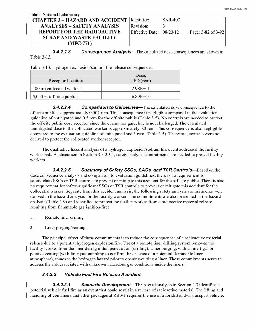
Form 412.09 (Rev. 10)
Idaho National Laboratory
CHAPTER 3 – HAZARD AND ACCIDENT ANALYSES – SAFETY ANALYSIS
REPORT FOR THE RADIOACTIVE SCRAP AND WASTE FACILITY
(MFC-771)
Identifier: Revision: Effective Date:
SAR-407 3 08/23/12 Page: 3-82 of 3-92
3.4.2.2.3 Consequence Analysis—The calculated dose consequences are shown in Table 3-13.
Table 3-13. Hydrogen explosion/sodium fire release consequences.
Receptor Location Dose,
TED (rem)
100 m (collocated worker) 2.98E−01
5,000 m (off-site public) 6.89E−03
3.4.2.2.4 Comparison to Guidelines—The calculated dose consequence to the off-site public is approximately 0.007 rem. This consequence is negligible compared to the evaluation guideline of anticipated and 0.5 rem for the off-site public (Table 3-5). No controls are needed to protect the off-site public dose receptor since the evaluation guideline is not challenged. The calculated unmitigated dose to the collocated worker is approximately 0.3 rem. This consequence is also negligible compared to the evaluation guideline of anticipated and 5 rem (Table 3-5). Therefore, controls were not derived to protect the collocated worker receptor.
The qualitative hazard analysis of a hydrogen explosion/sodium fire event addressed the facility worker risk. As discussed in Section 3.3.2.3.1, safety analysis commitments are needed to protect facility workers.
3.4.2.2.5 Summary of Safety SSCs, SACs, and TSR Controls—Based on the dose consequence analysis and comparison to evaluation guidelines, there is no requirement for safety-class SSCs or TSR controls to prevent or mitigate this accident for the off-site public. There is also no requirement for safety-significant SSCs or TSR controls to prevent or mitigate this accident for the collocated worker. Separate from this accident analysis, the following safety analysis commitments were derived in the hazard analysis for the facility worker. The commitments are also presented in the hazard analysis (Table 3-9) and identified to protect the facility worker from a radioactive material release resulting from flammable gas ignition/fire:
1. Remote liner drilling
2. Liner purging/venting.
The principal effect of these commitments is to reduce the consequences of a radioactive material release due to a potential hydrogen explosion/fire. Use of a remote liner drilling system removes the facility worker from the liner during initial penetration (drilling). Liner purging, with an inert gas or passive venting (with liner gas sampling to confirm the absence of a potential flammable liner atmosphere), removes the hydrogen hazard prior to opening/cutting a liner. These commitments serve to address the risk associated with unknown hazardous gas conditions inside the liners.
3.4.2.3 Vehicle Fuel Fire Release Accident
3.4.2.3.1 Scenario Development—The hazard analysis in Section 3.3 identifies a potential vehicle fuel fire as an event that could result in a release of radioactive material. The lifting and handling of containers and other packages at RSWF requires the use of a forklift and/or transport vehicle.
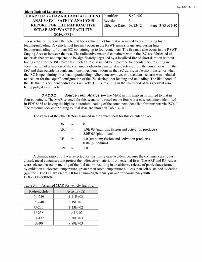
Form 412.09 (Rev. 10)
Idaho National Laboratory
CHAPTER 3 – HAZARD AND ACCIDENT ANALYSES – SAFETY ANALYSIS
REPORT FOR THE RADIOACTIVE SCRAP AND WASTE FACILITY
(MFC-771)
Identifier: Revision: Effective Date:
SAR-407 3 08/23/12 Page: 3-83 of 3-92
These vehicles introduce the potential for a vehicle fuel fire that is assumed to occur during liner loading/unloading. A vehicle fuel fire may occur in the RSWF main storage area during liner loading/unloading to/from an ISC containing up to four containers. The fire may also occur in the RSWF Staging Area or between the two. The radioactive material containers within the ISC are fabricated of materials that are not expected to be significantly degraded by a localized fire of short duration without taking credit for the ISC materials. Such a fire is assumed to impact the four containers, resulting in volatilization of a fraction of the contained radioactive material and release from the container within the ISC and then outside through small openings/penetrations in the ISC during in-facility transfer, or when the ISC is open during liner loading/unloading. Albeit conservative, this accident scenario was included to account for the “open” configuration of the ISC during liner loading and unloading. The likelihood of the HE that this accident addresses is unlikely (HE 3), resulting in the likelihood of this accident also being judged as unlikely.
3.4.2.3.2 Source Term Analysis—The MAR in this analysis is limited to that in four containers. The MAR selected for this scenario is based on the four worst-case containers identified in EDF-8685 as having the highest plutonium loading of the containers identified for transport via ISCs.51 The radionuclides contributing to total dose are shown in Table 3-14.
The values of the other factors assumed in the source term for this calculation are:
DR = 0.1 ARF = 1.0E-03 (uranium; fission and activation products)
3.0E-05 (plutonium) RF = 1.0 (uranium; fission and activation products)
0.04 (plutonium) LPF = 1.0
A damage ratio of 0.1 was selected for this fire release accident because the containers are robust, closed, metal containers that protect the radioactive material from external fires. The ARF and RF values were selected based on melting of the fuel matrix resulting in an airborne release of particulates formed by oxidation at elevated temperature, greater than room temperature but less than self-sustained oxidation (ignition). The LPF was set to 1.0 for an unmitigated analysis and for consistency with DOE-STD-3009-94.
Table 3-14. Assumed MAR for vehicle fuel fire. Radionuclide Activity (Ci)
Pu-239 1.41E+02 Pu-240 9.19E+01 U-235 1.13E−02 U-238 1.41E-02 Cs-137 6.30E+03 Sr-90 9.89E+03

Form 412.09 (Rev. 10)
Idaho National Laboratory
CHAPTER 3 – HAZARD AND ACCIDENT ANALYSES – SAFETY ANALYSIS
REPORT FOR THE RADIOACTIVE SCRAP AND WASTE FACILITY
(MFC-771)
Identifier: Revision: Effective Date:
SAR-407 3 08/23/12 Page: 3-84 of 3-92
3.4.2.3.3 Consequence Analysis—The calculated consequences for a fire that engulfs four containers is shown in Table 3-1532
Table 3-15. Vehicle fuel fire release consequences.
Dose in rem (TED)
Material-at-Risk
Dose Receptor Location 100 m
Collocated Worker 5,000 m
Off-site Public
Uranium isotopes 7.36E−05 9.68E−07
Plutonium isotopes 4.39E−03 1.55E−04
Fission/activation products 3.95E−01 8.45E−03
Sum of doses (rem) 3.99E−01 8.61E−03
3.4.2.3.4 Comparison to Guidelines—The calculated dose consequence to the off-site public is approximately 0.009 rem. This consequence is negligible compared to the evaluation guideline of unlikely and 5.0 rem for the off-site public (Table 3-5). No controls are needed to protect the off-site public dose receptor since the evaluation guideline is not challenged.
The calculated unmitigated dose to the collocated worker is approximately 0.4 rem. This consequence is negligible compared to the evaluation guideline of unlikely and 25 rem for the collocated worker (Table 3-5). Therefore, controls were not derived to protect the collocated worker receptor.
The qualitative hazard analysis of a vehicle fuel fire resulting in a release of radioactive material addressed the facility worker risk. Based on that evaluation, no controls were derived to protect the facility worker receptor for inhalation dose consequences from this accident scenario.
The qualitative hazard analysis of a vehicle fuel fire resulting in direct radiation exposure addressed facility worker risk. As discussed in Section 3.3.2.3.3, controls are needed to protect facility workers from direct radiation exposure.
3.4.2.3.5 Summary of Safety SSCs, SACs, and TSR Controls—Based on the consequence analysis results and comparison to guidelines, there is no requirement for safety-class SSCs or TSR controls to prevent or mitigate this accident for the off-site public. Furthermore, there is no requirement for safety-significant SSCs or TSR controls to prevent or mitigate this accident for the collocated worker. Separate from this accident analysis, the following TSR-level controls were derived in the hazard analysis to protect the facility worker from direct radiation exposure. The following controls are also presented in the hazard analysis (Table 3-9) and identified to protect the facility worker from direct radiation exposure resulting from a vehicle fuel fire:
1. Supplemental radiological control (TSR-level SAC)
2. Radiation protection program (INL safety management program).

Form 412.09 (Rev. 10)
Idaho National Laboratory
CHAPTER 3 – HAZARD AND ACCIDENT ANALYSES – SAFETY ANALYSIS
REPORT FOR THE RADIOACTIVE SCRAP AND WASTE FACILITY
(MFC-771)
Identifier: Revision: Effective Date:
SAR-407 3 08/23/12 Page: 3-85 of 3-92
The supplemental radiological control directs the facility dose rate limit of 5 R/hr from ISC external surfaces is not exceeded allowing for the expected reduction in direct radiation during container handling and transfer operations. The radiation protection program is also selected as a control for this hazard to reduce exposure to direct radiation through the use of temporary shielding and appropriate radiation monitoring. The overall result is a reduction in the facility worker risk to an acceptable level.
3.4.2.4 Inadvertent Nuclear Criticality Accident
3.4.2.4.1 Scenario Development—The hazard analysis in Section 3.3 identified the potential for a criticality accident at RSWF. As shown in Table 3-9 and discussed in Section 3.3.2.3.6, a criticality accident at RSWF is considered unlikely in the absence of controls because of the limited operational capabilities at RSWF. Containers handled and stored at RSWF are packaged and loaded at other facilities. A criticality accident at RSWF is most closely associated with operational events (over-batching) originating at these external facilities.
The potential dose consequence from a criticality accident at RSWF is addressed semi-quantitatively herein, based on the criticality dose evaluation performed for the Fuel Manufacturing Facility (FMF).61,62
• A bounding fission yield of 1E+18 for a moderated metal system
While there are differences between the facilities and their attendant operations, the need to perform a quantitative analysis specific to RSWF was deemed unwarranted because criticality (unshielded) is a function of the characteristics of the critical system (fissions, etc.) and not the facility, per se. The cited criticality accident consequences were calculated based on the following assumptions:
• A single burst.
Chapter 6 provides the criticality safety analysis for operations conducted at RSWF. Section 6.3.3 addresses criticality concerns specific to RSWF and summarizes the criticality accident scenarios. The scenarios are derived from the RSWF CSE. Controls are derived to satisfy the double contingency criterion specified in DOE O 420.1B, “Facility Safety.”15 The application of controls is judged to reduce the likelihood of a criticality accident to beyond extremely unlikely.56
3.4.2.4.2 Source Term Development—The source term for the direct dose evaluation are the neutrons, gamma rays, and neutron-induced secondary gamma rays from a moderated metal (Pu) system as discussed in Reference 62.
3.4.2.4.3 Consequence Analysis—The criticality accident consequence evaluation results, from Reference 62, are listed in Table 3-16 for the unshielded condition. The results are for an unshielded criticality modeled as a point source. By inspection, Table 3-16 indicates that doses to in-facility workers, and possibly other workers in near-proximity to the facility, are likely to be lethal in the unshielded scenario. The unmitigated dose to the collocated worker at 100 m is 95 rem. No discernible direct radiation dose is expected to the off-site public at a distance of 5,000 m.
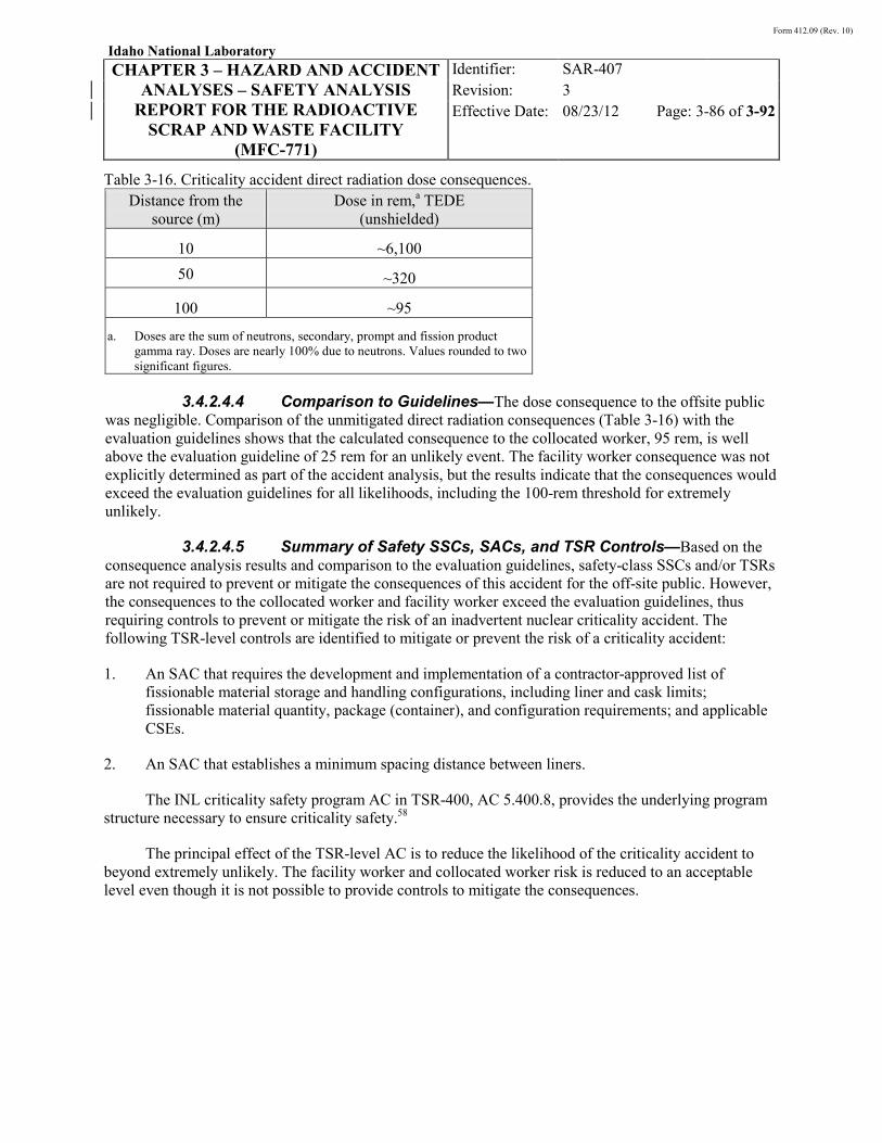
Form 412.09 (Rev. 10)
Idaho National Laboratory
CHAPTER 3 – HAZARD AND ACCIDENT ANALYSES – SAFETY ANALYSIS
REPORT FOR THE RADIOACTIVE SCRAP AND WASTE FACILITY
(MFC-771)
Identifier: Revision: Effective Date:
SAR-407 3 08/23/12 Page: 3-86 of 3-92
Table 3-16. Criticality accident direct radiation dose consequences. Distance from the
source (m) Dose in rem,a TEDE
(unshielded)
10 ~6,100 50 ~320
100 ~95
a. Doses are the sum of neutrons, secondary, prompt and fission product gamma ray. Doses are nearly 100% due to neutrons. Values rounded to two significant figures.
3.4.2.4.4 Comparison to Guidelines—The dose consequence to the offsite public
was negligible. Comparison of the unmitigated direct radiation consequences (Table 3-16) with the evaluation guidelines shows that the calculated consequence to the collocated worker, 95 rem, is well above the evaluation guideline of 25 rem for an unlikely event. The facility worker consequence was not explicitly determined as part of the accident analysis, but the results indicate that the consequences would exceed the evaluation guidelines for all likelihoods, including the 100-rem threshold for extremely unlikely.
3.4.2.4.5 Summary of Safety SSCs, SACs, and TSR Controls—Based on the consequence analysis results and comparison to the evaluation guidelines, safety-class SSCs and/or TSRs are not required to prevent or mitigate the consequences of this accident for the off-site public. However, the consequences to the collocated worker and facility worker exceed the evaluation guidelines, thus requiring controls to prevent or mitigate the risk of an inadvertent nuclear criticality accident. The following TSR-level controls are identified to mitigate or prevent the risk of a criticality accident:
1. An SAC that requires the development and implementation of a contractor-approved list of fissionable material storage and handling configurations, including liner and cask limits; fissionable material quantity, package (container), and configuration requirements; and applicable CSEs.
2. An SAC that establishes a minimum spacing distance between liners.
The INL criticality safety program AC in TSR-400, AC 5.400.8, provides the underlying program structure necessary to ensure criticality safety.58
The principal effect of the TSR-level AC is to reduce the likelihood of the criticality accident to beyond extremely unlikely. The facility worker and collocated worker risk is reduced to an acceptable level even though it is not possible to provide controls to mitigate the consequences.

Form 412.09 (Rev. 10)
Idaho National Laboratory
CHAPTER 3 – HAZARD AND ACCIDENT ANALYSES – SAFETY ANALYSIS
REPORT FOR THE RADIOACTIVE SCRAP AND WASTE FACILITY
(MFC-771)
Identifier: Revision: Effective Date:
SAR-407 3 08/23/12 Page: 3-87 of 3-92
3.4.3 Beyond Design Basis Accidents
DOE-STD-3009-94 requires the evaluation of accidents beyond the design (or evaluation) basis to provide a perspective of the residual risk associated with the operation of a facility or activity. For RSWF operations, one beyond design basis accident (BDBA) is a radioactive material release with a higher damage ratio than that assumed in the accident analysis. Because of the limited operations performed at RSWF, and the equipment used, the controls that were selected previously for the evaluation basis accidents are the same controls that would be selected in an event with a higher damage ratio. Therefore, no new controls would need to be derived to reduce the risk to an acceptable level for the receptors that exceed evaluation guidelines by reducing the likelihood of the events.
Another BDBA would be an NPH load that exceeds a PC-2 seismic event. The RSWF seismic evaluation was performed assuming a PC-2 seismic event based on the criteria and guidance provided in DOE O 420.1B,15 DOE G 420.1-2,16 and the associated standards. The RSWF seismic evaluation concluded that under saturated conditions, the soil could undergo liquefaction in a seismic event, resulting in the liners floating to the surface of the soil. The phenomenon of liquefaction occurs when the buoyancy force of the saturated soil exceeds the force (weight) of the item in the soil, in this case a liner and its contents. A seismic load that exceeds that of a PC-2 event is expected to result in the same types of effects, but with a lower likelihood because the return frequency of a PC-3 even is less than that of a PC-2 event. No controls have been identified that could reduce or prevent potential consequences from a seismic event that exceeds PC-2.
3.5 References
1. 10 CFR 830, Subpart B, “Safety Basis Requirements,” Code of Federal Regulations, Office of the Federal Register.
2. DOE-STD-1027-92, “Hazard Categorization and Accident Analysis Techniques for Compliance with DOE Order 5480.23, Nuclear Safety Analysis Reports,” U.S. Department of Energy, December 1992 (including Change 1, September 1997).
3. DOE-STD-3009-94, “Preparation Guide for U.S. Department of Energy Nonreactor Nuclear Facility Documented Safety Analyses,” U.S. Department of Energy, current revision.
4. DOE G 421.1-2, “Implementation Guide for Use in Developing Documented Safety Analyses to Meet Subpart B of 10 CFR 830,” U.S. Department of Energy.
5. 29 CFR 1910.119, “Process Safety Management of Highly Hazardous Chemicals,” Code of Federal Regulations, Office of the Federal Register.
6. DOE G 423.1-1, “Implementation Guide for Use in Developing Technical Safety Requirements,” U.S. Department of Energy, current revision.
7. DOE-STD-1186-2004, “Specific Administrative Controls,” U.S. Department of Energy, current revision.
Form 412.09 (Rev. 10)
Idaho National Laboratory
CHAPTER 3 – HAZARD AND ACCIDENT ANALYSES – SAFETY ANALYSIS
REPORT FOR THE RADIOACTIVE SCRAP AND WASTE FACILITY
(MFC-771)
Identifier: Revision: Effective Date:
SAR-407 3 08/23/12 Page: 3-88 of 3-92
8. M. L. Adams (DOE-ID Contracting Officer) letter to L. A. Sehlke, “Nuclear Safety Rule Supplemental Information,” OS-QSD-05-121, CCN 202983, October 11, 2005.
9. DOE-STD-5506-2007, “Preparation of Safety Basis Documents for Transuranic (TRU) Waste Facilities,” U.S. Department of Energy, April 2007.
10. NS-18104, “INL Guide to Safety Analysis Methodology,” Rev. 5, May 2009.
11. AIChE, Guidelines for Hazard Evaluation Procedures, with Worked Examples, New York: American Institute of Chemical Engineers, 1992 edition.
12. HAD-429, “Radioactive Scrap and Waste Facility Fire Hazards Analysis,” Rev. 0, May 2008.
13. WSRC-MS-92-206, “Toxic Chemical Hazard Classification and Risk Acceptance Guidelines for Use in DOE Facilities: Recommendations of the Westinghouse M&O Nuclear Facility Safety Committee Subcommittee on Nonradiological Risk Acceptance Guidelines Development,” Rev. 2, March 24, 1995.
14. U.S. Department of Energy, Protective Action Criteria (PAC) with AEGLs, ERPGs and TEELs for Chemicals of Concern Web Page, www.hss.energy.gov/HealthSafety/WSHP/chem_safety/teel.html, August 2007, Rev. 23, Web page visited July 28, 2008.
15. DOE O 420.1B, “Facility Safety,” U.S. Department of Energy, current revision.
16. DOE G 420.1-2, “Guide for the Mitigation of Natural Phenomena Hazards for DOE Nuclear Facilities and Nonnuclear Facilities,” U.S. Department of Energy, March 2000.
17. DOE-STD-1020-2002, “Natural Phenomena Hazards Design and Evaluation Criteria for Department of Energy Facilities,” U.S. Department of Energy, January 2002.
18. DOE-STD-1021-93, “Natural Phenomena Hazards Performance Categorization Guidelines for Structures, Systems, and Components,” U.S. Department of Energy, July 1993 (including Change 1, January 1996).
19. DOE-STD-1022-94, “Natural Phenomena Hazards Site Characterization Criteria,” U.S. Department of Energy, March 1994 (including Change 1, January 1996).
20. DOE-STD-1023-95, “Natural Phenomena Hazards Assessments Criteria,” U.S. Department of Energy, September 1995 (including Change 1, January 1996).
21. TEV-13, “History of the Radioactive Scrap and Waste Facility HERO Database,” current revision.
22. 40 CFR 302, “Designation, Reportable Quantities, and Notification,” Code of Federal Regulations, Office of the Federal Register.
Form 412.09 (Rev. 10)
Idaho National Laboratory
CHAPTER 3 – HAZARD AND ACCIDENT ANALYSES – SAFETY ANALYSIS
REPORT FOR THE RADIOACTIVE SCRAP AND WASTE FACILITY
(MFC-771)
Identifier: Revision: Effective Date:
SAR-407 3 08/23/12 Page: 3-89 of 3-92
23. DOE-HDBK-1081-94, “Primer on Spontaneous Heating and Pyrophoricity,” U.S. Department of Energy, December 1994.
24. TRA-Landlord-1752, “ETR FS&R Hazard Assessment of the Eutectic Solution of Sodium and Potassium (NaK) and Sodium (Na),” September 2001.
25. ANCR-1217, “An Explosive Hazards Analysis of the Eutectic Solution NaK and KO2,” Aerojet Nuclear Company, June 1975.
26. Type A Accident Investigation Report, “December 8, 1999 Multiple Injury Accident Resulting from the Sodium-Potassium Explosion in Building 9201-5 at the Y-12 Plant,” DOE Office of Oversight, Safety and Health, February 2000.
27. 40 CFR 355, “Emergency Planning and Notification,” Code of Federal Regulations, Office of the Federal Register.
28. DOE-STD-1136, “Guide of Good Practices for Occupational Radiological Protection in Uranium Facilities,” U.S. Department of Energy, current revision.
29. ECAR-150, “Radioactive Scrap and Waste Facility (RSWF) Dose Consequence Calculations for Fire and Explosion Scenarios,” Rev. 0, June 2008.
30. ECAR-151, “RSWF Direct Radiation Evaluation,” Rev. 0, June 2008.
31. EDF-6684, “Thermal Analysis for the HFEF-5 and -14 Casks,” Rev. 1, January 2007.
32. ECAR-1352, “Evaluation of Dose Consequences for Radioactive Scrap and Waste Facility (RSWF) Safety Analysis Report (SAR) Revision,” Rev. 0, August 2011.
33. ECAR-150, “Radioactive Scrap and Waste Facility (RSWF) Dose Consequence Calculations for Fire and Explosion Scenarios,” Rev. 0, June 2008.
34. ECAR-151, “RSWF Direct Radiation Evaluation,” Rev. 0, June 2008.
35. EDF-6684, “Thermal Analysis for the HFEF-5 and -14 Casks,” Rev. 1, January 2007.
36. TBL-191, “Shielding Calculations for the Modified Interim Storage Container (ISC) for HFEF Canisters,” Idaho Cleanup Project, Rev. 1, June 2009.
37. W7710-0122-ES, “RSWF Evaluation of Hydrogen Vulnerability,” Rev. 1, April 2002.
38. F0000-0096-ES, “Evaluation of the Radiological Dose Associated with the Receipt of Breached Elements in the Fuel Conditioning Facility,” Rev. 0, May 2004.
39. DOE-HDBK-1081-94, “Primer on Spontaneous Heating and Pyrophoricity,” U.S. Department of Energy, December 1994.
Form 412.09 (Rev. 10)
Idaho National Laboratory
CHAPTER 3 – HAZARD AND ACCIDENT ANALYSES – SAFETY ANALYSIS
REPORT FOR THE RADIOACTIVE SCRAP AND WASTE FACILITY
(MFC-771)
Identifier: Revision: Effective Date:
SAR-407 3 08/23/12 Page: 3-90 of 3-92
40. ECAR-149, “Radioactive Scrap and Waste Facility (RSWF) Dose Consequence Calculations for Drop Scenarios,” Rev. 0, June 2008.
41. F3003-0026-AQ, “Impact Test for the HFEF-5 Waste Can,” September 1991.
42. F3630-0242-ES, “TRU-RH Waste Can Assembly Drop Test Report,” Rev. 0, September 2002.
43. ECAR-1827, “RSWF Equipment Loading Adjacent to Liners,” Rev. 1, June 2012.
44. EDF-6509, “Low Temperature Accidental Drop Analysis of the HFEF-5 Cask,” Rev. 1, June 2006.
45. EDF-7152, “HFEF-14 Cask Low Temperature Drop Analysis,” Rev. 0, October 2006.
46. G. Silkworth (CH2M-Hill) technical memorandum to L. Witbeck (ANL-W), “Preliminary Corrosion Investigation at RSWF Site,” 100688, October 6, 1988.
47. W. S. Spickelmire and G. H. Silkworth (CH2M-Hill) letter to R. L. Brookshire (ANL-W), “Conceptual Design for Cathodic Protection of RSWF Liners at the ANL-W Site,” BOI27770.A1, June 2, 1989.
48. W7710-0127-SA, “RSWF Accident Analysis,” Rev. 0, April 2004.
49. TBL-300, “Shielding Calculations for the Facility Transfer Container (FTC),” Rev. 0, Idaho Cleanup Project, September 2010.
50. ECAR-619, “RSWF Remote Handled Transuranic Waste Transfer Dose Rate Analysis,” Rev. 0, May 2009.
51. EDF-8685, “RWDP Consequence Analysis Dose Calculations,” Idaho Cleanup Project, Rev. 9, August 2010.
52. USQ-9646, “RH TRU Retrieval (RSWF) and Transport of Lot 5 24-in. Large Liners and SLSF Containers,” Idaho Cleanup Project, August 2010.
53. LRD-15001, “INL Radiological Control Manual,” current revision.
54. 10 CFR 835, “Occupational Radiation Protection,” Code of Federal Regulations, Office of the Federal Register.
55. W7000-0161-ES, “A Report on EBR-II Special Components Considered as Candidates for Treatment Using the MEDE Process,” Rev. 0, September 2006.
56. INL/INT-08-14180, “Criticality Safety Evaluation for the Radioactive Scrap and Waste Facility (MFC-771),” Rev. 0, July 2008.
57. SAR-400, “INL Standardized Safety Analysis Report,” current revision.
Form 412.09 (Rev. 10)
Idaho National Laboratory
CHAPTER 3 – HAZARD AND ACCIDENT ANALYSES – SAFETY ANALYSIS
REPORT FOR THE RADIOACTIVE SCRAP AND WASTE FACILITY
(MFC-771)
Identifier: Revision: Effective Date:
SAR-407 3 08/23/12 Page: 3-91 of 3-92
58. TSR-400, “INL Standardized Technical Safety Requirements,” current revision.
59. INL/EXT-05-00642, “RSAC 6.2 with WinRP 2.0, User Manual,” Rev. 0, September 2005.
60. DOE-HDBK-3010-94, “Airborne Release Fractions/Rates and Respirable Fractions for Nonreactor Nuclear Facilities,” U.S. Department of Energy, December 1994 (including Change 1, March 2000).
61. EDF-6425, “Bounding Criticality Accident Fission Yields for the Fuel Manufacturing Facility,” Rev. 0, May 2006.
62. EDF-6478, “Criticality Accident Dose Evaluation for the Fuel Manufacturing Facility,” Rev. 2, September 2009.

Form 412.09 (Rev. 10)
Idaho National Laboratory
CHAPTER 3 – HAZARD AND ACCIDENT ANALYSES – SAFETY ANALYSIS
REPORT FOR THE RADIOACTIVE SCRAP AND WASTE FACILITY
(MFC-771)
Identifier: Revision: Effective Date:
SAR-407 3 08/23/12 Page: 3-92 of 3-92
INTENTIONALLY BLANK
Form 412.09 (Rev. 10)
Idaho National Laboratory
CHAPTER 4 – SAFETY STRUCTURES, SYSTEMS, AND COMPONENTS –
SAFETY ANALYSIS REPORT FOR THE RADIOACTIVE SCRAP AND WASTE
FACILITY (MFC-771)
Identifier: Revision: Effective Date:
SAR-407 3 08/23/12 Page: 4-1 of 4-6
CHAPTER 4
SAFETY STRUCTURES, SYSTEMS, AND COMPONENTS

Form 412.09 (Rev. 10)
Idaho National Laboratory
CHAPTER 4 – SAFETY STRUCTURES, SYSTEMS, AND COMPONENTS –
SAFETY ANALYSIS REPORT FOR THE RADIOACTIVE SCRAP AND WASTE
FACILITY (MFC-771)
Identifier: Revision: Effective Date:
SAR-407 3 08/23/12 Page: 4-2 of 4-6
CONTENTS
4. SAFETY STRUCTURES, SYSTEMS, AND COMPONENTS ..................................................... 4-3
4.1 Introduction ........................................................................................................................ 4-3
4.2 Requirements ...................................................................................................................... 4-3
4.3 Safety-Class Structures, Systems, and Components .......................................................... 4-3
4.4 Safety-Significant Structures, Systems, and Components .................................................. 4-3
4.4.1 Shielded Transfer Casks ................................................................................. 4-3
4.5 References .......................................................................................................................... 4-5

Form 412.09 (Rev. 10)
Idaho National Laboratory
CHAPTER 4 – SAFETY STRUCTURES, SYSTEMS, AND COMPONENTS –
SAFETY ANALYSIS REPORT FOR THE RADIOACTIVE SCRAP AND WASTE
FACILITY (MFC-771)
Identifier: Revision: Effective Date:
SAR-407 3 08/23/12 Page: 4-3 of 4-6
4. SAFETY STRUCTURES, SYSTEMS, AND COMPONENTS
4.1 Introduction
This chapter identifies and describes the structures, systems, and components (SSCs) associated with RSWF operations that are safety-class or safety-significant. These safety SSCs are derived from the hazard and accident analyses presented in Chapter 3. This chapter provides details on the safety function, system description, functional requirements, system evaluation, and controls for each safety SSC.
4.2 Requirements
The following standards and DOE direction are applicable to this chapter:
• DOE-STD-3009-94, “Preparation Guide for U.S. Department of Energy Nonreactor Nuclear Facility Documented Safety Analyses”1
• Nuclear safety rule supplemental information from DOE-ID.
2
4.3 Safety-Class Structures, Systems, and Components
Safety-class SSCs are defined as SSCs whose preventive or mitigative function is needed in order to meet the risk evaluation guidelines for the off-site public. Based on the accident analyses in Chapter 3, no safety-class SSCs were identified for RSWF operations because the risk to the off-site public did not exceed the INL risk evaluation guidelines.
4.4 Safety-Significant Structures, Systems, and Components
An SSC is designated safety-significant if its preventive or mitigative function is a major contributor to defense-in-depth (prevention of uncontrolled release of radioactive or other hazardous material) and/or worker safety. The evaluation guidelines and selection criteria used to determine when safety-significant SSCs are necessary are presented in Reference 3, and additional guidance is provided in NS-18104, “INL Guide to Safety Analysis Methodology.”3
Based on the hazard analysis presented in Chapter 3, the following SSC is designated safety-significant:
• Shielded transfer casks (HFEF-5 and HFEF-14).
A detailed description of this safety-significant SSC and a discussion of how it meets the functional requirements and performs the safety function are provided in the following section.
4.4.1 Shielded Transfer Casks
4.4.1.1 Safety Function. The safety functions of each approved shielded transfer cask designated as safety-significant SSCs at RSWF are to reduce direct radiation exposure and reduce radioactive material release during normal and postulated accident conditions.

Form 412.09 (Rev. 10)
Idaho National Laboratory
CHAPTER 4 – SAFETY STRUCTURES, SYSTEMS, AND COMPONENTS –
SAFETY ANALYSIS REPORT FOR THE RADIOACTIVE SCRAP AND WASTE
FACILITY (MFC-771)
Identifier: Revision: Effective Date:
SAR-407 3 08/23/12 Page: 4-4 of 4-6
4.4.1.2 System Description. The HFEF-5 and HFEF-14 shielded transfer casks are briefly described in Chapter 2, and additional detail is provided in the cask-specific system design description.4,5
4.4.1.3 Functional Requirements. The functional requirements of the shielded transfer casks are as follows:
• Each cask provides shielding to protect workers from direct radiation exposure during normal and accident conditions
• Each cask provides confinement of container/content during normal and accident conditions.
4.4.1.4 System Evaluation. The casks have been evaluated to ensure that the safety functions and functional requirements identified in Sections 4.4.1.1 and 4.4.1.3 are satisfied.
4.4.1.4.1 Performance Criteria—The performance criteria for the HFEF-5 and HFEF-14 casks are as follows:
• Shielding analysis that demonstrates the ability of the cask to provide shielding capability of 200 mrem/h on the external surface of the cask and 10 mrem/h at 2 m from the surface of the cask or per the INL radiation protection program requirements (PLN-260, “INL Radiation Protection Program”6) specifically following the INL Radiation Control Manual (LRD-15001, “Radiological Control Manual”7
• Structural analysis that demonstrates the ability of the cask to confine the container/contents and provide shielding. Each cask is to maintain (1) confinement of container/content (cask integrity and the cask closure devices remain on the cask), and (2) radiation shielding following the maximum postulated accidents during in-facility container movement(s).
) per the Radiological Health and Safety Policy.
4.4.1.4.2 Evaluation—The expected performance of the HFEF-5 and HFEF-14 casks under postulated drop scenarios onto a concrete surface has been evaluated.8,9
The ability of the casks to provide shielding capability of 200 mrem/h on the external surface of the cask for an assumed source term has been evaluated.
The evaluations considered cask drops from a height of 6 ft with low temperature conditions (i.e., −40°F), while loaded with a generic outer can (representative of the cask-specific double can configuration). The evaluation concluded that the outer steel shell, lead shielding, and doors of the casks experience varying degrees of damage, but will typically contain their payload. The evaluation also showed that an outer can may experience plastic deformation and strain, but not to a degree that a breach occurs. Catastrophic failure of the cask is not expected for any of the drop impacts evaluated.
10,11

Form 412.09 (Rev. 10)
Idaho National Laboratory
CHAPTER 4 – SAFETY STRUCTURES, SYSTEMS, AND COMPONENTS –
SAFETY ANALYSIS REPORT FOR THE RADIOACTIVE SCRAP AND WASTE
FACILITY (MFC-771)
Identifier: Revision: Effective Date:
SAR-407 3 08/23/12 Page: 4-5 of 4-6
4.4.1.5 TSR Controls. The TSR-level control applicable to in-facility movement(s) of containers within RSWF recommends the use of the HFEF-5 or HFEF-14 cask when the container is compatible with the applicable cask and going to HFEF or FCF. The in-facility movement TSR specifies criteria that must be met during container movements in order to protect the bounds of the structural analysis applicable to each cask. In addition, TSR-400, “INL Standardized Technical Safety Requirements,”12
4.5 References
which contains the general programmatic TSRs that apply to all INL nuclear facilities, is also applicable. Each approved safety-significant cask is a passive design feature and compliance with TSR-400 ensures that programs are in place to ensure the effectiveness of the design features identified as safety-significant SSCs.
1. DOE-STD-3009-94, Change Notice 3, “Preparation Guide for U.S. Department of Energy Nonreactor Nuclear Facility Documented Safety Analyses,” U.S. Department of Energy, March 2006.
2. M. L. Adams (DOE-ID Contracting Officer) to L. A. Sehlke, “Nuclear Safety Rule Supplemental Information,” OS-QSD-05-121, CCN 202983, October 11, 2005.
3. NS-18104, “INL Guide to Safety Analysis Methodology,” Rev. 5, May 2009.
4. SDD-201, “HFEF-5 Waste Cask,” current revision.
5. SDD-202, “HFEF-14 Waste Cask,” current revision.
6. PLN-260, “INL Radiation Protection Program,” current revision.
7. LRD-15001, “Radiological Control Manual,” current revision.
8. EDF-6509, “Low Temperature Accidental Drop Analysis of the HFEF-5 Cask,” Rev. 1, June 2006.
9. EDF-7152, “HFEF-14 Cask Low Temperature Drop Analysis,” Rev. 0, October 2006.
10. ECAR-151, “Radioactive Scrap and Waste Facility (RSWF) Dose Consequence Calculations for Direct Radiation Exposure Scenarios,” Rev. 0, June 2008.
11. EDF-6642, “Radiological Consequence Calculations for the HFEF-14 Cask,” Rev. 0, May 2006.
12. TSR-400, “INL Standardized Technical Safety Requirements,” current revision.
Form 412.09 (Rev. 10)
Idaho National Laboratory
CHAPTER 4 – SAFETY STRUCTURES, SYSTEMS, AND COMPONENTS –
SAFETY ANALYSIS REPORT FOR THE RADIOACTIVE SCRAP AND WASTE
FACILITY (MFC-771)
Identifier: Revision: Effective Date:
SAR-407 3 08/23/12 Page: 4-6 of 4-6
INTENTIONALLY BLANK

Form 412.09 (Rev. 10)
Idaho National Laboratory
CHAPTER 5 – DERIVATION OF TECHNICAL SAFETY
REQUIREMENTS – SAFETY ANALYSIS REPORT FOR THE RADIOACTIVE
SCRAP AND WASTE FACILITY (MFC-771)
Identifier: Revision: Effective Date:
SAR-407 3 08/23/12 Page: 5-1 of 5-12
CHAPTER 5
DERIVATION OF TECHNICAL SAFETY REQUIREMENTS
Form 412.09 (Rev. 10)
Idaho National Laboratory
CHAPTER 5 – DERIVATION OF TECHNICAL SAFETY
REQUIREMENTS – SAFETY ANALYSIS REPORT FOR THE RADIOACTIVE
SCRAP AND WASTE FACILITY (MFC-771)
Identifier: Revision: Effective Date:
SAR-407 3 08/23/12 Page: 5-2 of 5-12
CONTENTS
5. DERIVATION OF TECHNICAL SAFETY REQUIREMENTS ................................................... 5-3
5.1 Introduction ........................................................................................................................ 5-3
5.2 Requirements ...................................................................................................................... 5-3
5.3 Technical Safety Requirements Coverage .......................................................................... 5-3
5.4 Derivation of Facility Modes .............................................................................................. 5-6
5.5 TSR Derivation ................................................................................................................... 5-6
5.5.1 Container Position (LCO/SAC 3.407.1) ......................................................... 5-6 5.5.1 Supplemental Radiological Control (LCO/SAC 3.407.2) .............................. 5-7 5.5.2 Container Handling Limit (AC 5.407.1) ......................................................... 5-7 5.5.3 RSWF In-facility Movements (AC 5.407.2) ................................................... 5-8 5.5.4 Cask Seating Requirement (AC 5.407.3) ........................................................ 5-8 5.5.5 Staffing Requirement (AC 5.407.4) ................................................................ 5-9 5.5.6 Soil Excavation Control (AC 5.407.5) .......................................................... 5-10 5.5.7 Criticality Safety Controls (AC 5.407.6) ...................................................... 5-10
5.6 Design Features ................................................................................................................ 5-11
5.7 Interface with TSRs from Other Facilities ....................................................................... 5-11
5.8 References ........................................................................................................................ 5-11
TABLE
Table 5-1. Summary of derived controls – SSCs and TSRs. ..................................................................... 5-4

Form 412.09 (Rev. 10)
Idaho National Laboratory
CHAPTER 5 – DERIVATION OF TECHNICAL SAFETY
REQUIREMENTS – SAFETY ANALYSIS REPORT FOR THE RADIOACTIVE
SCRAP AND WASTE FACILITY (MFC-771)
Identifier: Revision: Effective Date:
SAR-407 3 08/23/12 Page: 5-3 of 5-12
5. DERIVATION OF TECHNICAL SAFETY REQUIREMENTS
5.1 Introduction TSRs for operation of RSWF consist of general programmatic TSRs in TSR-400, “INL
Standardized Technical Safety Requirements,”1
5.2 Requirements
and TSRs derived specifically from the RSWF hazard and accident analysis. Together, the general and RSWF-specific TSRs prescribe the bounds for safe operation of RSWF necessary to protect the health and safety of the public and reduce risk to workers.
10 CFR 830, Subpart B, “Safety Basis Requirements”2; DOE G 423.1-1, “Implementation Guide for Use in Developing Technical Safety Requirements”3; and DOE-STD-3009-94, “Preparation Guide for U.S. Department of Energy Nonreactor Nuclear Facility Documented Safety Analyses,”4 establish the requirements and guidelines for performing hazard and accident analyses and a methodology for hazard categorization. Additional guidance, including risk evaluation guidelines for the development of TSRs for nonreactor nuclear facilities at the INL, has been established by DOE-ID.5 With respect to TSRs, this guidance also includes the methodology contained in DOE-STD-1186-2004, “Specific Administrative Controls.”6
TSRs are those requirements that define the conditions, safe boundaries, and programmatic controls necessary to ensure the safe operation of a nuclear facility and to reduce the potential risk to the public and workers from uncontrolled releases of radioactive or hazardous materials or from radiation exposures due to an inadvertent criticality. DOE G 423.1-1 delineates the criteria, scope, content, and format for the development and documentation of TSRs.
5.3 Technical Safety Requirements Coverage Table 5-1 lists the RSWF safety SSCs and TSRs identified in Chapters 3 and 4 that are needed to
reduce facility and collocated worker risk to an acceptable level, or to protect the bounds of analysis. Table 5-1 cross-references the HEs or accidents (per Chapter 3) leading to the derivation of TSRs and/or the identification of safety SSCs for their preventive/mitigative functions.

Form 412.09 (Rev. 10)
Idaho National Laboratory
CHAPTER 5 – DERIVATION OF TECHNICAL SAFETY
REQUIREMENTS – SAFETY ANALYSIS REPORT FOR THE RADIOACTIVE
SCRAP AND WASTE FACILITY (MFC-771)
Identifier: Revision: Effective Date:
SAR-407 3 08/23/12 Page: 5-4 of 5-12
Table 5-1. Summary of derived controls – SSCs and TSRs. Hazardous Event/Accident
(Chapter 3) SSC Description
(Chapter 4) SC SS Technical Safety Requirement
(SL, LCS, LCO, or AC) Comment
Fire and explosion (direct radiation exposure and/or radioactive material release) (Section 3.3.2.3.1)
NA NA Radiation protection program INL safety management program
Radioactive material release – facility operations (Section 3.3.2.3.2)
Shielded transfer casks (Section 4.4.1)
X AC 5.407.1 Container handling limit
AC 5.407.2 RSWF in-facility movements
Radiation protection program INL safety management program
Emergency preparedness program
AC 5.400.9
Hoisting and rigging program AC 5.400.12
Radioactive material release – Other (Section 3.3.2.3.3)
NA NA

Form 412.09 (Rev. 10)
Idaho National Laboratory
CHAPTER 5 – DERIVATION OF TECHNICAL SAFETY
REQUIREMENTS – SAFETY ANALYSIS REPORT FOR THE RADIOACTIVE
SCRAP AND WASTE FACILITY (MFC-771)
Identifier: Revision: Effective Date:
SAR-407 3 08/23/12 Page: 5-5 of 5-12
Table 5-1. (continued).
Hazardous Event/Accident (Chapter 3)
SSC Description (Chapter 4) SC SS
Technical Safety Requirement (SL, LCS, LCO, or AC) Comment
Direct radiation exposure (Section 3.3.2.3.4)
Shielded transfer casks (Section 4.4.1)
X LCO/SAC 3.407.1
Container position SAC in LCO format
LCO/SAC 3.407.2
Supplemental radiological control
SAC in LCO format
AC 5.407.1 Container handling limit
AC 5.407.3 Cask seating requirement
AC 5.407.4 Staffing requirement
AC 5.407.5 Soil excavation control
Radiation protection program INL safety management program
Emergency preparedness program
AC 5.400.9
Hoisting and rigging program AC 5.400.12
Hazardous Material Release (Section 3.3.2.3.5)
NA NA
Inadvertent nuclear criticality (Section 3.3.2.3.6)
NA AC 5.407.6 Criticality safety controls
External events (Section 3.3.2.3.7) NA NA
Natural phenomena hazards (Section 3.3.2.3.8)
NA Radiation protection program INL safety management program
Hoisting and rigging program AC 5.400.12
AC administrative control SC safety-class
LCO limiting condition for operation SL safety limit
LCS limiting control setting SS safety-significant
SAC Specific Administrative Control

Form 412.09 (Rev. 10)
Idaho National Laboratory
CHAPTER 5 – DERIVATION OF TECHNICAL SAFETY
REQUIREMENTS – SAFETY ANALYSIS REPORT FOR THE RADIOACTIVE
SCRAP AND WASTE FACILITY (MFC-771)
Identifier: Revision: Effective Date:
SAR-407 3 08/23/12 Page: 5-6 of 5-12
5.4 Derivation of Facility Modes No mode-related operational TSRs (SLs, LCSs, limiting conditions for operation [LCOs], or
surveillance requirements) are derived for RSWF. Therefore, no specific operational modes are required for the RSWF and associated operations.
5.5 TSR Derivation
The hazard and accident analyses in Chapter 3 show that the risk of direct radiation exposures, radioactive material releases, and criticality is above evaluation guidelines. TSRs have been developed to prevent and/or mitigate these accidents. This section identifies the safety bases for the derivation of the TSRs listed in Table 5-1.
5.5.1 Container Position (LCO/SAC 3.407.1)
A TSR SAC has been derived that establishes a required container position relative to the top of a transfer cask/FTC during container transfer between a shielded transfer cask/FTC and liner when using the cask/FTC bottom load option. The SAC requires that action be taken to return a container that has been lifted beyond the top of a cask/FTC to a safety configuration within the transfer cask/FTC for evaluation, unless the radiation hazard or other worker safety concern preempts such return.
Safety function. The safety function of container position requirement is to prevent a container from being inadvertently lifted out the top of a shielded transfer cask/FTC during liner loading and unloading activities when using the cask/FTC bottom load option.
Control summary. The control was derived as a SAC because the hazard analysis risk binning indicated that risk reduction needed to be at the level provided by a safety SSC, if an appropriate safety SSC were available. The SAC is written in LCO format in TSR-407 and establishes a container position, relative to the top of the shielded transfer cask/FTC, during liner loading or unloading when using the cask/FTC bottom load option. The control also requires that action be taken to return a container to a safe configuration for evaluation within the cask/FTC if any portion of the container is lifted beyond the top of the cask. The SAC serves to reduce the risk of direct radiation exposure to the facility worker.
Bases summary. During the transfer of containers between liners and the shielded transfer casks/FTCs when using the bottom load option, the top of the casks/FTC are open, and containers are raised and lowered using a crane. There is no engineered feature on the crane or cask/FTC that prevents inadvertently lifting a container out the top of the transfer cask/FTC. Once outside the cask/FTC, the container is no longer shielded, resulting in facility worker exposure to a potentially significant direct radiation hazard. The purpose of the control is to ensure the container remains within the body of the transfer cask/FTC.
Control evaluation. Adherence to the SAC serves to reduce the risk of facility worker exposure to direct radiation.

Form 412.09 (Rev. 10)
Idaho National Laboratory
CHAPTER 5 – DERIVATION OF TECHNICAL SAFETY
REQUIREMENTS – SAFETY ANALYSIS REPORT FOR THE RADIOACTIVE
SCRAP AND WASTE FACILITY (MFC-771)
Identifier: Revision: Effective Date:
SAR-407 3 08/23/12 Page: 5-7 of 5-12
5.5.1 Supplemental Radiological Control (LCO/SAC 3.407.2)
A TSR SAC is derived requiring that temporary shielding be installed, or other mitigative measures be established, to maintain the direct radiation exposure rate below 5 R/hr during liner loading and unloading operations involving a shielded transfer cask, or shielded FTC, or ISC or liner.
Safety function. The safety function of the supplemental radiological control is to reduce the risk of direct radiation exposure between the bottom of the cask and the soil surface during liner loading and unloading operations.
Control summary. The control was derived as a SAC because the hazard analysis risk binning indicated that risk reduction needed to be at the level provided by a safety SSC, if an appropriate safety SSC were available. The SAC is written in LCO format in TSR-407, and requires that temporary shielding be installed, or other mitigative measures be established, to maintain the direct radiation exposure rate below 5 R/hr during liner loading and unloading operations involving the shielded transfer cask, or shielded FTC, or ISC, or liner. The SAC serves to reduce the risk of direct radiation exposure to the facility worker.
Bases summary
The shielded transfer cask, shielded FTC, ISC, and liner/soil provide shielding of the direct radiation hazard associated with the radioactive material stored at RSWF. During open-air transfers, the containers and overpacked liners are in an unshielded configuration resulting in facility worker exposure to a potentially significant direct radiation hazard. This SAC requires that temporary shielding be installed, or other mitigative measures be established, to maintain the direct radiation exposure rate below 5 R/hr during open-air transfer of containers and overpacked liners involving a shielded transfer cask, FTC, or ISC.
. The shielded transfer cask, or shielded FTC, or ISC and liner/soil provide shielding of the direct radiation hazard associated with the radioactive material stored at RSWF. During the transfer of containers between a cask and liner, a positioning device (not applicable to the FTC) is used to aid in alignment of the cask over the liner. Although the positioning device provides shielding from the direct radiation hazard when the container is between the cask and soil, the dose reduction benefit of the device has not been quantified, nor does the device completely eliminate the existence of gaps between the cask and the soil. Such gaps may pose a pathway for streaming radiation during the time the container is between the soil and the cask. This SAC requires that temporary shielding be installed, or other mitigative measures be established, to maintain the direct radiation exposure rate below 5 R/hr during liner loading or unloading operations involving a shielded transfer cask.
Control evaluation
5.5.2 Container Handling Limit (AC 5.407.1)
. Adherence to the SAC serves to reduce the risk of direct radiation exposure to facility workers during liner loading and unloading.
A TSR SAC is derived that limits the handling of containers to one at any given time.
Safety function. The safety function of the container handling limit is to protect the bounds of analysis for the container drop accident by limiting the number of containers involved in the event.
Form 412.09 (Rev. 10)
Idaho National Laboratory
CHAPTER 5 – DERIVATION OF TECHNICAL SAFETY
REQUIREMENTS – SAFETY ANALYSIS REPORT FOR THE RADIOACTIVE
SCRAP AND WASTE FACILITY (MFC-771)
Identifier: Revision: Effective Date:
SAR-407 3 08/23/12 Page: 5-8 of 5-12
Control summary. The control was derived as an SAC since the risk binning in the hazard analysis indicated the risk reduction needed to be at the level provided by a safety SSC if an appropriate SSC were available. The SAC is a directed action statement in TSR-407. The control requires that the number of containers being handled at any one time be limited to one.
Bases summary. The SAC addresses the risk of a radioactive material release due to a drop during container handling. The SAC is written in general terms, rather than specific terms of mass or dose equivalence, to provide operational flexibility.
Control evaluation
5.5.3 RSWF In-facility Movements (AC 5.407.2)
. Adherence to this SAC minimizes the amount of radioactive material present outside of a storage location, while still accommodating operations needs.
A TSR SAC is derived that establishes requirements for container movements made solely within RSWF (i.e., in-facility movements).
Safety function. The safety function of the in-facility movement requirement is to prevent a radioactive material release and/or direct radiation exposure in the event of a cask, FTC, or ISC drop or other handling mishap during container movements within RSWF.
Control summary. The control was derived as an SAC because the hazard analysis risk binning indicated that risk reduction needed to be at the level provided by a safety SSC, if an appropriate safety SSC were available. The SAC is a directed action statement in TSR-407, and requires the use of the casks (HFEF-5 and HFEF-14), FTCs, or ISCs for in-facility movement of containers, when such containers are compatible with the applicable cask, FTC, or ISC.
Bases summary. Operations at RSWF, RSWF Staging Area, and between the two, include lifting, handling and movement of containers using heavy equipment, including a forklift, crane, and/or shielded transfer casks, FTCs, or ISCs. Such movements must be conducted in a manner that ensures the risk of facility worker exposure to a radioactive material release or to direct radiation is at an acceptable level. The RSWF in-facility movement SAC identifies the conditions that must be met prior to initiating, and during the performance of, such movements.
Control evaluation
5.5.4 Cask Seating Requirement (AC 5.407.3)
. Adherence to the SAC reduces the magnitude of facility worker exposure to a radioactive material release or direct radiation in the event of a handling mishap during container movements within RSWF.
A TSR SAC is derived that requires the shielded transfer cask to be fully seated on the positioning device prior to liner loading or unloading.
Safety function. The safety function of the cask seating requirement is to reduce the direct radiation hazard during liner loading and unloading activities.

Form 412.09 (Rev. 10)
Idaho National Laboratory
CHAPTER 5 – DERIVATION OF TECHNICAL SAFETY
REQUIREMENTS – SAFETY ANALYSIS REPORT FOR THE RADIOACTIVE
SCRAP AND WASTE FACILITY (MFC-771)
Identifier: Revision: Effective Date:
SAR-407 3 08/23/12 Page: 5-9 of 5-12
Control summary. The control was derived as a SAC because the hazard analysis risk binning indicated that risk reduction needed to be at the level provided by a safety SSC, if an appropriate safety SSC were available. The SAC is a directed action statement in TSR-407, and requires that the cask be fully seated on the positioning device prior to initiating the transfer of a radioactive material container between the liner and the cask. Although the steel positioning devices provide some shielding from the direct radiation hazard associated with the radioactive material handled at RSWF, temporary shielding or other controls may also be used in conjunction with the positioning device, to reduce the risk of direct radiation exposure to acceptable levels. The cask seating requirement serves to minimize the gap between the cask and positioning device. The control applies only when a shielded transfer cask is used in the loading or unloading of a liner.
Bases summary. The shielded transfer cask and liner/soil provide shielding of the direct radiation hazard associated with the radioactive material stored at RSWF. During the transfer of containers between a cask and liner, a positioning device is used to aid in alignment of cask over the liner. The cask seating requirement minimizes the gap between the cask and the positioning device, reducing the direct radiation hazard that exists during the transfer of a container between the liner and the cask (i.e., during the time the container is between the liner/soil and the cask).
Control evaluation
5.5.5 Staffing Requirement (AC 5.407.4)
. Adherence to the SAC serves to reduce the risk of direct radiation exposure to facility workers during liner loading and unloading.
A TSR SAC is derived for staffing to ensure that a qualified operator or shift supervisor is available to confirm container position and cask seating during container transfer between a shielded transfer cask and liner.
Safety function. The safety function of the staffing requirement is to prevent direct radiation exposure.
Control summary. The control was derived as a SAC because the hazard analysis risk binning indicated that risk reduction needed to be at the level provided by a safety SSC, if an appropriate safety SSC were available. The SAC is a directed action statement in TSR-407. In the absence of an engineered control, the staffing requirement ensures that qualified operations personnel are present during liner loading and unloading activities. Staffing requirements are applicable during transfer of radioactive material containers between a shielded transfer cask and liner.
Bases summary. During the transfer of containers between liners and the shielded transfer casks, the top of the casks are open. Containers are raised and lowered within the cask cavity using a crane, which connects to the containers through the open top of the cask. There is no engineered feature on the crane or cask that prevents inadvertently lifting a container out the top of the transfer cask. Once outside the cask, the container is no longer shielded, resulting in facility worker exposure to a potentially significant direct radiation hazard. The purpose of the control is to provide staffing, which complements the container position requirement, relative to the top of the transfer cask, to prevent lifting a container out the top of the cask. The staffing control also provides assurance that a cask is seated on the positioning device prior to initiating the transfer of a container between the cask and liner.

Form 412.09 (Rev. 10)
Idaho National Laboratory
CHAPTER 5 – DERIVATION OF TECHNICAL SAFETY
REQUIREMENTS – SAFETY ANALYSIS REPORT FOR THE RADIOACTIVE
SCRAP AND WASTE FACILITY (MFC-771)
Identifier: Revision: Effective Date:
SAR-407 3 08/23/12 Page: 5-10 of 5-12
Control evaluation
5.5.6 Soil Excavation Control (AC 5.407.5)
. Adherence to the SAC serves to reduce the risk of facility worker exposure to direct radiation.
A TSR SAC is derived to ensure radiation protection during soil excavation activities within RSWF.
Safety function. The safety function of the soil excavation control is to prevent direct radiation exposure.
Control summary. The control was derived as a SAC because the hazard analysis risk binning indicated that risk reduction needed to be at the level provided by a safety SSC, if an appropriate safety SSC were available. The SAC is a directed action statement in TSR-407 and requires that soil excavation activities be evaluated and appropriate radiation protection controls and monitoring be established, prior to commencement of soil excavation within the facility. The SAC applies to soil excavation activities in which soil is intentionally removed through use of heavy equipment or other means. The SAC does not apply to routine or periodic soil cover maintenance activities that result in only nominal soil disturbance near the top of the liners.
Bases summary. The soil in which the liners are located provides shielding from the radiation hazard associated with the radioactive material stored therein. Soil excavation, laterally or vertically, can result in a reduction or elimination of the shielding function provided by the soil. In the absence of engineered shielding features, the soil excavation requirement serves to prevent direct radiation exposure during soil removal through proper evaluation and control.
Control evaluation
5.5.7 Criticality Safety Controls (AC 5.407.6)
. Adherence to the SAC serves to reduce the risk of facility worker exposure to direct radiation.
A TSR SAC is derived to provide limits on controlled parameters to prevent a criticality accident.
Safety function. The safety function of the control that addresses nuclear criticality safety is to prevent an inadvertent nuclear criticality at RSWF.
Control summary. The control was derived as an SAC because the risk binning in the hazard analysis indicated that risk reduction was necessary at the level provided by a safety SSC, if an appropriate SSC were available. The SAC is a directed action statement in TSR-407, and requires the development of a contractor-approved list (or lists) that addresses fissionable material storage and handling at RSWF. The SAC specifies that the list provide specific requirements for fissionable material quantities, configurations, and containers/packages, and reference the applicable CSE(s). The SAC also requires that a minimum spacing requirement for the RSWF liner array be established.
Bases summary. The SAC includes those controls applied to parameters or conditions, as derived from the criticality safety analysis, which must be violated or exceeded before a criticality is possible. It has been concluded from the analysis that the likelihood of a criticality accident at RSWF is beyond

Form 412.09 (Rev. 10)
Idaho National Laboratory
CHAPTER 5 – DERIVATION OF TECHNICAL SAFETY
REQUIREMENTS – SAFETY ANALYSIS REPORT FOR THE RADIOACTIVE
SCRAP AND WASTE FACILITY (MFC-771)
Identifier: Revision: Effective Date:
SAR-407 3 08/23/12 Page: 5-11 of 5-12
extremely unlikely taking into account the nature of the operations, fissionable materials/configurations, and the implementation of ACs. With the specific details of fissionable material handling and storage documented in a contractor-approved list, and establishment of a minimum liner spacing distance, assurance is provided that only those facility operations that lead to the analyzed packaging and storage configurations and circumstances are allowed.
Control evaluation
5.6 Design Features
. Adherence to the SAC prevents a criticality accident.
Passive design features are those design features that, if altered or modified, would have a significant effect on safe operation. These features are selected as safety SSCs and described in Chapter 4. Design features are controlled and maintained under the configuration control program in TSR-400. The passive safety-significant SSCs identified from the hazard and accident analysis in Chapter 3 are the shielded transfer casks (HFEF-5 and HFEF-14).
5.7 Interface with TSRs from Other Facilities
There is one interface point with TSRs for other MFC facilities or activities that affect RSWF. Specifically, transfers of radioactive material (HC-3 or greater quantities) from RSWF to other MFC facilities, or from other MFC facilities to RSWF, are performed in accordance with the safety analysis report and TSRs for MFC inter-facility transfers (SAR/TSR-413).
5.8 References
1. TSR-400, “INL Standardized Technical Safety Requirements,” current revision.
2. 10 CFR 830, Subpart B, “Safety Basis Requirements,” Code of Federal Requirements, Office of the Federal Register.
3. DOE G 423.1-1, “Implementation Guide for Use in Developing Technical Safety Requirements,” U.S. Department of Energy, October 2001.
4. DOE-STD-3009-94, Change 3, “Preparation Guide for U.S. Department of Energy Nonreactor Nuclear Facility Documented Safety Analyses,” U.S. Department of Energy, March 2006.
5. M. L. Adams (DOE-ID Contracting Officer) letter to L. A. Sehlke, “Nuclear Safety Rule Supplemental Information,” OS-QSD-05-121, CCN 202983, October 2005.
6. DOE-STD-1186-2004, “Specific Administrative Controls,” U.S. Department of Energy, August 2004.
Form 412.09 (Rev. 10)
Idaho National Laboratory
CHAPTER 5 – DERIVATION OF TECHNICAL SAFETY
REQUIREMENTS – SAFETY ANALYSIS REPORT FOR THE RADIOACTIVE
SCRAP AND WASTE FACILITY (MFC-771)
Identifier: Revision: Effective Date:
SAR-407 3 08/23/12 Page: 5-12 of 5-12
INTENTIONALLY BLANK

Form 412.09 (Rev. 10)
Idaho National Laboratory
CHAPTER 6 — PREVENTION OF INADVERTENT CRITICALITY – SAFETY
ANALYSIS REPORT FOR THE RADIOACTIVE SCRAP AND WASTE
FACILITY (MFC-771)
Identifier: Revision: Effective Date:
SAR-407 3 08/23/12 Page: 6-1 of 6-8
CHAPTER 6
PREVENTION OF INADVERTENT CRITICALITY

Form 412.09 (Rev. 10)
Idaho National Laboratory
CHAPTER 6 — PREVENTION OF INADVERTENT CRITICALITY – SAFETY
ANALYSIS REPORT FOR THE RADIOACTIVE SCRAP AND WASTE
FACILITY (MFC-771)
Identifier: Revision: Effective Date:
SAR-407 3 08/23/12 Page: 6-2 of 6-8
CONTENTS
6. PREVENTION OF INADVERTENT CRITICALITY ................................................................... 6-3
6.1 Introduction ........................................................................................................................ 6-3
6.2 Requirements ...................................................................................................................... 6-3
6.3 Criticality Concerns ............................................................................................................ 6-3
6.4 Criticality Controls ............................................................................................................. 6-6
6.4.1 Engineered Controls........................................................................................ 6-6 6.4.2 Administrative Controls .................................................................................. 6-6 6.4.3 Application of Double Contingency Principle ................................................ 6-6
6.5 Criticality Safety Program .................................................................................................. 6-7
6.6 Criticality Instrumentation .................................................................................................. 6-7
6.7 References .......................................................................................................................... 6-8
TABLE
Table 6-1. Simplified criticality safety scope for RSWF activities and operations. .................................. 6-5

Form 412.09 (Rev. 10)
Idaho National Laboratory
CHAPTER 6 — PREVENTION OF INADVERTENT CRITICALITY – SAFETY
ANALYSIS REPORT FOR THE RADIOACTIVE SCRAP AND WASTE
FACILITY (MFC-771)
Identifier: Revision: Effective Date:
SAR-407 3 08/23/12 Page: 6-3 of 6-8
6. PREVENTION OF INADVERTENT CRITICALITY
6.1 Introduction
This chapter summarizes the approach to criticality safety and the controls for the prevention of an inadvertent nuclear criticality at RSWF. The hazard analysis in Section 3.3 identified inadvertent nuclear criticality as a potential hazard at RSWF due to the presence of sufficient quantities of fissionable materials. This chapter identifies the engineering and ACs necessary for prevention of a criticality accident.
6.2 Requirements
The requirements for the INL Criticality Safety Program are listed in Chapter 6, “Prevention of Inadvertent Criticality,” of SAR-400, “INL Standardized Safety Analysis Report.”1
The criticality safety program requirements and recommendations for INL facilities, including RSWF, and the basis for deriving operational criticality safety limits, are described in LRD-18001, “INL Criticality Safety Program Requirements Manual.”
There are no unique requirements for RSWF.
2
6.3 Criticality Concerns
Chapter 2 of this SAR provides descriptions of RSWF operations and activities and an overview of the radioactive materials in the facility. The facility radioactive material inventory includes the fissionable material inventory as discussed in Chapter 3. Sufficient quantities of fissionable materials are associated with RSWF operations and activities that the risk of an inadvertent criticality must be evaluated. Fissionable material is packaged at other facilities prior to receipt at RSWF for storage. No packages are opened, or otherwise reconfigured, once received at RSWF. For RSWF storage and transfer operations, casks are typically used to transfer containers within the facility and during liner loading and unloading.
With respect to determining criticality concerns, the INL Criticality Safety Program requirements are stated in Chapter 6 of SAR-400. The fundamental requirement is that criticality safety analysis be performed to document that a process will be subcritical under both normal and credible abnormal conditions. In addition, the purpose of the analysis is to identify the controlled parameters and the limits on these parameters. For RSWF operations and activities, the quantities of fissionable material present are sufficient for criticality. The criticality safety analysis is documented in a CSE performed in accordance with procedures that implement the INL Criticality Safety Program.

Form 412.09 (Rev. 10)
Idaho National Laboratory
CHAPTER 6 — PREVENTION OF INADVERTENT CRITICALITY – SAFETY
ANALYSIS REPORT FOR THE RADIOACTIVE SCRAP AND WASTE
FACILITY (MFC-771)
Identifier: Revision: Effective Date:
SAR-407 3 08/23/12 Page: 6-4 of 6-8
The CSE for RSWF (INL/INT-08-14180, “Criticality Safety Evaluation for the Radioactive Scrap and Waste Facility [MFC-771]”3
• Storage and transfer of fissionable materials, including miscellaneous radioactive waste/scrap, EBR-II fuel elements (driver, blanket, and experimental), and EBR-II blanket subassemblies (INL/INT-08-14180 and EDF-7224, “Criticality Safety Evaluation for MFC Inter-Facility Transfers of Spent Nuclear Fuel Using the HFEF-5 Cask”
) addresses fissionable material storage, handling and transfer configurations for normal and abnormal conditions and provides the technical basis for determining the controlled parameters and applicable limits for these activities at RSWF. The RSWF CSE established a set of controls for storage and transfer of fissionable material at RSWF (in storage as of 2008), and incorporated by reference, limits and controls established in other approved CSEs that govern the storage, handling and transfer of fissionable material stored at RSWF. The scope of the overall CSEs is as follows:
4
• Uranium product ingots (EDF-6631, “Criticality Safety Evaluation for the Transport of HUP’s, UPS’s, and Waste Containers in the HFEF-5 Cask”
)
5
As discussed in Chapter 2 (Section 2.5.1), the radioactive material inventory in RSWF, which includes the fissionable material inventory with respect to this chapter, is expected to vary over time. Materials in different forms, containers, package configurations, and from different programs, etc., may be stored, handled, or transferred at the facility. As necessary, additional criticality safety analysis (CSEs or studies) is performed to determine the controlled parameters and limits. Consequently, it is expected that the criticality safety analysis (as documented in CSEs) will evolve over time as needed to support these changes in facility operations and the associated effect on material inventory. The CSEs cited above provide the necessary analysis to define the initial boundary for the RSWF criticality safety analysis, but they do not, in and of themselves, constitute a limitation on future facility operations.
).
Collectively, the cited CSEs establish or define overall facility scope with respect to criticality safety. Based on the CSEs, the key features of that scope are the storage and transfer equipment (liners and casks) and the types of fissionable material. These key features can be simplified and summarized as shown in Table 6-1.

Form 412.09 (Rev. 10)
Idaho National Laboratory
CHAPTER 6 — PREVENTION OF INADVERTENT CRITICALITY – SAFETY
ANALYSIS REPORT FOR THE RADIOACTIVE SCRAP AND WASTE
FACILITY (MFC-771)
Identifier: Revision: Effective Date:
SAR-407 3 08/23/12 Page: 6-5 of 6-8
Table 6-1. Simplified criticality safety scope for RSWF activities and operations. Aspect Detail
Operational status • Fissionable material is in storage including lag storage (storage is defined as only in the liners)
• Fissionable material is being handled/transferred within RSWF
Types of storage equipmenta • Storage liners • Shielded transfer casks (HFEF-5 and HFEF-14) • Shielded FTCs • ISCs
Types of transfer equipment • Shielded transfer casks (HFEF-5 and HFEF-14) • Shielded FTCs • ISCs
Types of fissionable materialb • Miscellaneous fissionable material (e.g., waste, fuel scrap) • EBR-II blanket subassemblies • EBR-II fuel elements (driver, blanket, and experimental) • Uranium product ingots
a. In terms of storage equipment, the criticality safety analysis (per the CSEs) and this safety basis only encompass the equipment listed here.
b. In terms of fissionable material categories (types), the materials listed here represent the configurations considered in the cited CSEs. This initial list is not limiting; other fissionable material categories may be defined for storage and transfer, provided that specific CSEs with similar types of controls are developed, as necessary.
In addition to determining the controlled parameters and limits on those parameters, the CSEs also
define the bounds of the analysis (when necessary) that should also be considered in control selection. The bounds of analysis can include important assumptions used in the calculational modeling or the lack of an explicit calculation for a specific set of circumstances. As appropriate, important assumptions may be protected by controls and unanalyzed situations are prohibited or otherwise controlled.
Postulated criticality accident scenarios are derived from the CSEs, which determine the critical configurations. These scenarios include overbatching of containers, casks, and/or liners; damage or reconfiguration of fissionable material, such as from a container drop; and, water ingress into liners and containers. The CSEs address specific fissionable material configurations (e.g., EBR-II fuel elements and subassemblies, IWC/OWC/baskets), generic fissionable materials (in containers), and liner array (spacing).
For RSWF, the CSE (Reference 3) concluded that RSWF is critically safe for the identified storage and cask loadings evaluated in the analysis. The CSE further concludes that the likelihood of a criticality accident is beyond extremely unlikely based on the operations, fissionable material inventory, and implementation of the controls identified in the criticality analysis. Based on this conclusion, criticality accident scenarios were not explicitly defined for RSWF. Rather, a potential criticality accident with its associated consequences was addressed semi-quantitatively based on dose consequence calculations for another MFC HC-2 nuclear facility. The semi-quantitative criticality accident is discussed in Section 3.4.
Form 412.09 (Rev. 10)
Idaho National Laboratory
CHAPTER 6 — PREVENTION OF INADVERTENT CRITICALITY – SAFETY
ANALYSIS REPORT FOR THE RADIOACTIVE SCRAP AND WASTE
FACILITY (MFC-771)
Identifier: Revision: Effective Date:
SAR-407 3 08/23/12 Page: 6-6 of 6-8
6.4 Criticality Controls
6.4.1 Engineered Controls
Based on the CSE for RSWF, no engineered controls were identified or derived for the criticality safety of RSWF operations and activities. ECAR-1652, “RSWF Criticality Scenarios with a Concrete Shield Plug,”6
6.4.2 Administrative Controls
evaluates the possibility of a shield plug drop contributing to a criticality accident. Per ECAR-1652, a criticality accident is not credible due to the many improbable failures that must occur and drop features that must exist before a criticality accident could occur.
The ACs that provide for the criticality safety of RSWF operations and activities are listed below. As discussed in the accident analysis portion of Chapter 3 (see Section 3.4), criticality was included in the set of representative, bounding, and unique accidents for RSWF. The ACs for criticality accident prevention (the likelihood aspect of risk) have been derived from the previously cited CSEs in Section 6.3. The ACs are designated as a TSR consistent with Chapter 6 in SAR-400,1 DOE-STD-3007-2007, “Guidelines for Preparing Criticality Safety Evaluations at Department of Energy Non-Reactor Nuclear Facilities,”7 and INL safety analysis methodology.8
1. A SAC that requires the development and implementation of a contractor approved list of fissionable material storage, handling and transfer requirements, including container/package limits, liner and cask limits – prevents critical conditions.
The TSR is as follows:
2. A SAC that requires a minimum spacing distance of 4 in. between liners – prevents critical conditions.
The SAC listed above has an associated, and abbreviated, function statement. The applicable portion of Chapter 5 (see Section 5.5) provides expanded discussions of the TSR safety function, control and bases summary, and control evaluation, as appropriate to the type of TSR. Additional information is also provided in TSR-407, “Technical Safety Requirements for the Radioactive Scrap and Waste Facility (MFC 771).”9
6.4.3 Application of Double Contingency Principle
In accordance with DOE O 420.1B, the double contingency principle is a requirement that must be implemented for those nuclear facilities subject to its criticality safety requirements.10
1
The application of the double contingency principle from the perspective of the INL criticality safety program has been previously stated in Chapter 6 of SAR-400 and has been implemented in LRD-18001.2 In the case of RSWF operations and activities that involve the potential for a criticality accident, the ACs necessary to the application of the double contingency principle are stated, or embedded, in the CSEs. The AC identified above has been incorporated into the facility safety basis (per Section 6.4.2) to ensure a desired margin of safety against the occurrence of a criticality accident. The integration of the criticality safety analysis (CSEs) into the facility safety basis has been performed consistent with the guidance in DOE-STD-3007-2007 through the linkage between CSEs and the DSA.
Form 412.09 (Rev. 10)
Idaho National Laboratory
CHAPTER 6 — PREVENTION OF INADVERTENT CRITICALITY – SAFETY
ANALYSIS REPORT FOR THE RADIOACTIVE SCRAP AND WASTE
FACILITY (MFC-771)
Identifier: Revision: Effective Date:
SAR-407 3 08/23/12 Page: 6-7 of 6-8
6.5 Criticality Safety Program
The INL Criticality Safety Program, which implements DOE O 420.1B,10 applies to RSWF operations and activities. In accordance with the Order, RSWF is considered a fissionable material operation because the fissionable material quantities, previously discussed in Chapters 2 and 3, exceed single parameter limits. The INL Criticality Safety Program is documented in LRD-180012 and is described in Chapter 6 of SAR-400. The program description, which is applicable to RSWF operations, addresses the program elements necessary to a facility-specific safety basis as identified in DOE-STD-3009-94, “Preparation Guide for U.S. Department of Energy Nonreactor Nuclear Facility Safety Analysis.”11
6.6 Criticality Instrumentation
The requirements that determine the need for a CAS are included in LRD-18001,2 which implements the relevant requirements of DOE O 420.1B and its referenced standard, ANSI/ANS-8.3-1997, “Criticality Accident Alarm System.”12 From LRD-18001, the need for a CAS is evaluated for those activities with sufficient fissionable material inventories that criticality is a concern.a
By inspection of the material description in Section 2.5.1 and the fissionable material inventory discussed in Section 3.3.2.1, the quantities of fissionable material associated with RSWF operations and activities are more than sufficient for criticality. The likelihood of criticality in the absence of controls is unlikely (10−4 to 10−2 per year). The judgment of unlikely is due primarily to the limited scope of operations performed at RSWF (i.e., no opening or reconfiguring of containers or their contents). Based on current operations, inventory, and application of controls, the RSWF CSE
In addition, the INL Criticality Safety Program requires that a CAS be provided when there are credible criticality accident scenarios (probability of criticality is greater than 10−6 per year) that result in doses that exceed 12 rads in free air.
3 concluded that the likelihood of criticality is beyond extremely unlikely (i.e., is reduced to less than 10−6 per year) for all scenarios. Therefore, a CAS is not required for RSWF.
a. Specific fissionable material (per isotope) thresholds are provided in LRD-18001.

Form 412.09 (Rev. 10)
Idaho National Laboratory
CHAPTER 6 — PREVENTION OF INADVERTENT CRITICALITY – SAFETY
ANALYSIS REPORT FOR THE RADIOACTIVE SCRAP AND WASTE
FACILITY (MFC-771)
Identifier: Revision: Effective Date:
SAR-407 3 08/23/12 Page: 6-8 of 6-8
6.7 References
1. SAR-400, “INL Standardized Safety Analysis Report,” Chapter 6, “Prevention of Inadvertent Criticality,” current revision.
2. LRD-18001, “INL Criticality Safety Program Requirements Manual,” current revision.
3. INL/INT-08-14180, “Criticality Safety Evaluation for the Radioactive Scrap and Waste Facility (MFC-771),” Rev. 0, July 2008.
4. EDF-7224, “Criticality Safety Evaluation for MFC Inter-Facility Transfers of Spent Nuclear Fuel Using the HFEF-5 Cask,” Rev. 0, August 2006.
5. EDF-6631, “Criticality Safety Evaluation for the Transport of HUP’s, UPS’s, and Waste Containers in the HFEF-5 Cask,” Rev. 0, May 2006.
6. ECAR-1652, “RSWF Criticality Scenarios with a Concrete Shield Plug,” Rev. 0, August 2011.
7. DOE-STD-3007-2007, “Guidelines for Preparing Criticality Safety Evaluations at Department of Energy Non-Reactor Nuclear Facilities,” U.S. Department of Energy, February 2007.
8. NS-18104, “INL Guide to Safety Analysis Methodology,” current revision.
9. TSR-407, “Technical Safety Requirements for the Radioactive Scrap and Waste Facility (MFC 771),” current revision.
10. DOE O 420.1B, “Facility Safety,” U.S. Department of Energy, December 2005.
11. DOE-STD-3009-94, Change Notice 3, “Preparation Guide for U.S. Department of Energy Nonreactor Nuclear Facility Safety Analysis,” U.S. Department of Energy, March 2006.
12. ANSI/ANS-8.3-1997, “Criticality Accident Alarm System,” American National Standards Institute/American Nuclear Society, current revision.

Form 412.09 (Rev. 10)
Idaho National Laboratory
CHAPTER 7 – RADIATION PROTECTION – SAFETY ANALYSIS REPORT FOR THE RADIOACTIVE
SCRAP AND WASTE FACILITY (MFC-771)
Identifier: Revision: Effective Date:
SAR-407 3 08/23/12 Page: 7-1 of 7-4
CHAPTER 7
RADIATION PROTECTION

Form 412.09 (Rev. 10)
Idaho National Laboratory
CHAPTER 7 – RADIATION PROTECTION – SAFETY ANALYSIS REPORT FOR THE RADIOACTIVE
SCRAP AND WASTE FACILITY (MFC-771)
Identifier: Revision: Effective Date:
SAR-407 3 08/23/12 Page: 7-2 of 7-4
CONTENTS
7. RADIATION PROTECTION ......................................................................................................... 7-3
7.1 References .......................................................................................................................... 7-3

Form 412.09 (Rev. 10)
Idaho National Laboratory
CHAPTER 7 – RADIATION PROTECTION – SAFETY ANALYSIS REPORT FOR THE RADIOACTIVE
SCRAP AND WASTE FACILITY (MFC-771)
Identifier: Revision: Effective Date:
SAR-407 3 08/23/12 Page: 7-3 of 7-4
7. RADIATION PROTECTION
Chapter 7, “Radiation Protection,” of SAR-4001 has been standardized and describes the INL Radiation Protection Program, which is applicable to RSWF. The RSWF HWMA/RCRA permit2
Facility-specific features that provide protection against the direct radiation hazard from the containers handled and stored at RSWF include the soil in which the liners are located and shield plugs integral to the closed liners. Operational features include shielded transfer cask, cask positioning devices, and temporary shielding.
also includes a facility-specific radiological monitoring requirements. One such requirement includes an annual radiation survey of the thirteen radiation monitoring tubes installed at RSWF (described in Section 2.4.1.7). The survey is performed over the length of the inside of the tubes using an appropriate radiation monitoring instrument. The results are used to provide an indication of a potential release of radioactive/hazardous material from the liners at RSWF.
7.1 References
1. SAR-400, “INL Standardized Safety Analysis Report,” Chapter 7, “Radiation Protection,” current
revision.
2. PER-116, “HWMA RCRA Partial Permit, Materials and Fuels Complex,” EPA ID. No. 4890008952, current revision.

Form 412.09 (Rev. 10)
Idaho National Laboratory
CHAPTER 7 – RADIATION PROTECTION – SAFETY ANALYSIS REPORT FOR THE RADIOACTIVE
SCRAP AND WASTE FACILITY (MFC-771)
Identifier: Revision: Effective Date:
SAR-407 3 08/23/12 Page: 7-4 of 7-4
INTENTIONALLY BLANK
Form 412.09 (Rev. 10)
Idaho National Laboratory
CHAPTER 8 – HAZARDOUS MATERIAL PROTECTION – SAFETY ANALYSIS REPORT FOR THE RADIOACTIVE
SCRAP AND WASTE FACILITY (MFC-771)
Identifier: Revision: Effective Date:
SAR-407 3 08/23/12 Page: 8-1 of 8-4
CHAPTER 8
HAZARDOUS MATERIAL PROTECTION
Form 412.09 (Rev. 10)
Idaho National Laboratory
CHAPTER 8 – HAZARDOUS MATERIAL PROTECTION – SAFETY ANALYSIS REPORT FOR THE RADIOACTIVE
SCRAP AND WASTE FACILITY (MFC-771)
Identifier: Revision: Effective Date:
SAR-407 3 08/23/12 Page: 8-2 of 8-4
CONTENTS
8. HAZARDOUS MATERIAL PROTECTION ................................................................................. 8-3
8.1 Reference ............................................................................................................................ 8-3
Form 412.09 (Rev. 10)
Idaho National Laboratory
CHAPTER 8 – HAZARDOUS MATERIAL PROTECTION – SAFETY ANALYSIS REPORT FOR THE RADIOACTIVE
SCRAP AND WASTE FACILITY (MFC-771)
Identifier: Revision: Effective Date:
SAR-407 3 08/23/12 Page: 8-3 of 8-4
8. HAZARDOUS MATERIAL PROTECTION
Chapter 8, “Hazardous Material Protection,” of SAR-4001
8.1 Reference
has been standardized and describes provisions for the INL hazardous material protection program, which is applicable to RSWF. Facility/activity-specific hazardous material protection requirements beyond those described in Chapter 8 of SAR-400 have not been identified for RSWF.
1. SAR-400, “INL Standardized Safety Analysis Report,” Chapter 8, “Hazardous Material
Protection,” current revision.

Form 412.09 (Rev. 10)
Idaho National Laboratory
CHAPTER 8 – HAZARDOUS MATERIAL PROTECTION – SAFETY ANALYSIS REPORT FOR THE RADIOACTIVE
SCRAP AND WASTE FACILITY (MFC-771)
Identifier: Revision: Effective Date:
SAR-407 3 08/23/12 Page: 8-4 of 8-4
INTENTIONALLY BLANK

Form 412.09 (Rev. 10)
Idaho National Laboratory
CHAPTER 9 – RADIOACTIVE AND HAZARDOUS WASTE MANAGEMENT – SAFETY ANALYSIS REPORT FOR THE
RADIOACTIVE SCRAP AND WASTE FACILITY (MFC-771)
Identifier: Revision: Effective Date:
SAR-407 3 08/23/12 Page: 9-1 of 9-4
CHAPTER 9
RADIOACTIVE AND HAZARDOUS WASTE MANAGEMENT

Form 412.09 (Rev. 10)
Idaho National Laboratory
CHAPTER 9 – RADIOACTIVE AND HAZARDOUS WASTE MANAGEMENT – SAFETY ANALYSIS REPORT FOR THE
RADIOACTIVE SCRAP AND WASTE FACILITY (MFC-771)
Identifier: Revision: Effective Date:
SAR-407 3 08/23/12 Page: 9-2 of 9-4
CONTENTS
9. RADIOACTIVE AND HAZARDOUS WASTE MANAGEMENT .............................................. 9-3
9.1 Introduction ........................................................................................................................ 9-3
9.2 Requirements ...................................................................................................................... 9-3
9.3 Radioactive and Hazardous Waste Management Program and Organization .................... 9-3
9.4 Radioactive and Hazardous Waste Streams and Sources ................................................... 9-3
9.5 References .......................................................................................................................... 9-3

Form 412.09 (Rev. 10)
Idaho National Laboratory
CHAPTER 9 – RADIOACTIVE AND HAZARDOUS WASTE MANAGEMENT – SAFETY ANALYSIS REPORT FOR THE
RADIOACTIVE SCRAP AND WASTE FACILITY (MFC-771)
Identifier: Revision: Effective Date:
SAR-407 3 08/23/12 Page: 9-3 of 9-4
9. RADIOACTIVE AND HAZARDOUS WASTE MANAGEMENT
9.1 Introduction
A waste management program is in place at the INL to protect workers, the public, and the environment from the hazards associated with radioactive and hazardous waste stored and managed at RSWF.
9.2 Requirements
Chapter 9, “Radioactive and Hazardous Waste Management,” of SAR-4001 has been standardized and identifies the INL waste management program, which is applicable to RSWF. In addition to the requirements identified in SAR-400, RSWF is permitted as a miscellaneous storage unit under the Idaho Hazardous Waste Management Act (HWMA). The HWMA/RCRA permit2
9.3 Radioactive and Hazardous Waste Management Program and Organization
identifies unit-specific requirements applicable to storage of mixed radioactive wastes at RSWF.
Chapter 9 of SAR-400 describes the INL program and organization for managing radioactive, mixed, and hazardous waste, which applies to RSWF.
9.4 Radioactive and Hazardous Waste Streams and Sources
There are currently no radioactive, hazardous, or mixed waste streams generated from normal RSWF operations (i.e., storage, waste container handling, surveillance, and maintenance activities). In addition, there are no facility-specific waste handling or treatment systems at RSWF.
9.5 References
1. SAR-400, “INL Standardized Safety Analysis Report,” Chapter 9, “Radioactive and Hazardous Waste Management,” current revision.
2. PER-116, “HWMA RCRA Partial Permit Materials and Fuels Complex EPA ID No. 4890008952,” current revision.

Form 412.09 (Rev. 10)
Idaho National Laboratory
CHAPTER 9 – RADIOACTIVE AND HAZARDOUS WASTE MANAGEMENT – SAFETY ANALYSIS REPORT FOR THE
RADIOACTIVE SCRAP AND WASTE FACILITY (MFC-771)
Identifier: Revision: Effective Date:
SAR-407 3 08/23/12 Page: 9-4 of 9-4
INTENTIONALLY BLANK

Form 412.09 (Rev. 10)
Idaho National Laboratory
CHAPTER 10 – INITIAL TESTING, IN-SERVICE SURVEILLANCE, AND
MAINTENANCE – SAFETY ANALYSIS REPORT FOR THE RADIOACTIVE
SCRAP AND WASTE FACILITY (MFC-771)
Identifier: Revision: Effective Date:
SAR-407 3 08/23/12 Page: 10-1 of 10-4
CHAPTER 10
INITIAL TESTING, IN-SERVICE SURVEILLANCE, AND MAINTENANCE
Form 412.09 (Rev. 10)
Idaho National Laboratory
CHAPTER 10 – INITIAL TESTING, IN-SERVICE SURVEILLANCE, AND
MAINTENANCE – SAFETY ANALYSIS REPORT FOR THE RADIOACTIVE
SCRAP AND WASTE FACILITY (MFC-771)
Identifier: Revision: Effective Date:
SAR-407 3 08/23/12 Page: 10-2 of 10-4
CONTENTS
10. INITIAL TESTING, IN-SERVICE SURVEILLANCE, AND MAINTENANCE ....................... 10-3
10.1 References ........................................................................................................................ 10-3

Form 412.09 (Rev. 10)
Idaho National Laboratory
CHAPTER 10 – INITIAL TESTING, IN-SERVICE SURVEILLANCE, AND
MAINTENANCE – SAFETY ANALYSIS REPORT FOR THE RADIOACTIVE
SCRAP AND WASTE FACILITY (MFC-771)
Identifier: Revision: Effective Date:
SAR-407 3 08/23/12 Page: 10-3 of 10-4
10. INITIAL TESTING, IN-SERVICE SURVEILLANCE, AND MAINTENANCE
Chapter 10, “Initial Testing, In-Service Surveillance, and Maintenance,” of SAR-4001 has been standardized and describes the INL initial testing, in-service surveillance, and maintenance programs, which are applicable to RSWF operations. In addition to these programs, the RSWF HWMA/RCRA permit2
Corrosion monitoring of the liners consists primarily of the removal and examination of one empty corrosion surveillance liner (described in Section 2.4.1) every four years. The exhumed liner is inspected to assess the extent of corrosion. Inspection includes visual examination and measurement of wall thickness. The data resulting from the inspection and examination provides verification and assurance of the effectiveness of the CPS. The inspections are performed and/or supervised by an independent corrosion engineer and documented as part of the facility operating history.
includes requirements for monitoring corrosion of the liners, as described below.
10.1 References
1. SAR-400, “INL Standardized Safety Analysis Report,” Chapter 10, “Initial Testing, In-Service Surveillance, and Maintenance,” current revision.
2. PER-116, “HWMA RCRA Partial Permit, Materials and Fuels Complex,” EPA ID. No. 4890008952, current revision.
Form 412.09 (Rev. 10)
Idaho National Laboratory
CHAPTER 10 – INITIAL TESTING, IN-SERVICE SURVEILLANCE, AND
MAINTENANCE – SAFETY ANALYSIS REPORT FOR THE RADIOACTIVE
SCRAP AND WASTE FACILITY (MFC-771)
Identifier: Revision: Effective Date:
SAR-407 3 08/23/12 Page: 10-4 of 10-4
INTENTIONALLY BLANK
Form 412.09 (Rev. 10)
Idaho National Laboratory
CHAPTER 11 – OPERATIONAL SAFETY – SAFETY ANALYSIS REPORT FOR THE RADIOACTIVE SCRAP AND
WASTE FACILITY (MFC-771)
Identifier: Revision: Effective Date:
SAR-407 3 08/23/12 Page: 11-1 of 11-4
CHAPTER 11
OPERATIONAL SAFETY

Form 412.09 (Rev. 10)
Idaho National Laboratory
CHAPTER 11 – OPERATIONAL SAFETY – SAFETY ANALYSIS REPORT FOR THE RADIOACTIVE SCRAP AND
WASTE FACILITY (MFC-771)
Identifier: Revision: Effective Date:
SAR-407 3 08/23/12 Page: 11-2 of 11-4
CONTENTS
11. OPERATIONAL SAFETY ........................................................................................................... 11-3
11.1 Introduction ...................................................................................................................... 11-3
11.2 Requirements .................................................................................................................... 11-3
11.3 Conduct of Operations ...................................................................................................... 11-3
11.4 Fire Protection .................................................................................................................. 11-3
11.4.1 Fire Hazards .................................................................................................. 11-3 11.4.2 Fire Protection Program and Organization ................................................... 11-3 11.4.3 Combustible Loading Control ....................................................................... 11-3 11.4.4 Fire Fighting Capabilities ............................................................................. 11-3 11.4.5 Fire Fighting Readiness Assurance ............................................................... 11-3
11.5 References ........................................................................................................................ 11-4
Form 412.09 (Rev. 10)
Idaho National Laboratory
CHAPTER 11 – OPERATIONAL SAFETY – SAFETY ANALYSIS REPORT FOR THE RADIOACTIVE SCRAP AND
WASTE FACILITY (MFC-771)
Identifier: Revision: Effective Date:
SAR-407 3 08/23/12 Page: 11-3 of 11-4
11. OPERATIONAL SAFETY
11.1 Introduction
This chapter provides information specific to RSWF operations with respect to operational safety.
11.2 Requirements
Chapter 11, “Operational Safety,” of SAR-4001
11.3 Conduct of Operations
has been standardized and describes the INL operational safety program, which is applicable to RSWF. Facility/activity-specific operational safety requirements beyond those described in Chapter 11 of SAR-400 have not been identified for RSWF.
SAR-400, Chapter 11, summarizes the aspects of conduct of operations that are directly applicable to INL and its implementation at INL facilities, including RSWF.
11.4 Fire Protection
11.4.1 Fire Hazards
The major fire hazards present at RSWF include: (1) hydrogen explosion/deflagration in a liner, (2) vehicle fire, and (3) debris fire. The facility itself has no structure, thereby minimizing fire hazards at the facility. Where necessary, these hazards have been previously addressed in the Chapter 3 hazard analysis and are consistent with the RSWF FHA as documented in HAD-429.2
11.4.2 Fire Protection Program and Organization
The INL fire protection program, including safety management policies and philosophies and the organizational structure that administers the fire protection program, is described in SAR-400, Chapter 11.
11.4.3 Combustible Loading Control
RSWF does not require a formal combustible loading program due to the limited amount of combustible material handled and used at the facility.
11.4.4 Fire Fighting Capabilities
INL general fire fighting capabilities are discussed in SAR-400, Chapter 11. There are no unique fire fighting capabilities for RSWF. The only fire protection equipment at RSWF is portable fire extinguishers located in the office trailer and in the heavy equipment used in the facility.
11.4.5 Fire Fighting Readiness Assurance
SAR-400, Chapter 11, summarizes the fire prevention inspection program, the types and frequencies of fire safety drills and exercises, and fire protection program recordkeeping requirements.

Form 412.09 (Rev. 10)
Idaho National Laboratory
CHAPTER 11 – OPERATIONAL SAFETY – SAFETY ANALYSIS REPORT FOR THE RADIOACTIVE SCRAP AND
WASTE FACILITY (MFC-771)
Identifier: Revision: Effective Date:
SAR-407 3 08/23/12 Page: 11-4 of 11-4
11.5 References
1. SAR-400, “INL Standardized Safety Analysis Report,” Chapter 11, “Operational Safety,” current revision.
2. HAD-429, “Radioactive Scrap and Waste Facility Fire Hazards Analysis,” Rev. 0, May 20, 2008.

Form 412.09 (Rev. 10)
Idaho National Laboratory
CHAPTER 12 – PROCEDURES AND TRAINING – SAFETY ANALYSIS
REPORT FOR THE RADIOACTIVE SCRAP AND WASTE FACILITY
(MFC-771)
Identifier: Revision: Effective Date:
SAR-407 3 08/23/12 Page: 12-1 of 12-4
CHAPTER 12
PROCEDURES AND TRAINING

Form 412.09 (Rev. 10)
Idaho National Laboratory
CHAPTER 12 – PROCEDURES AND TRAINING – SAFETY ANALYSIS
REPORT FOR THE RADIOACTIVE SCRAP AND WASTE FACILITY
(MFC-771)
Identifier: Revision: Effective Date:
SAR-407 3 08/23/12 Page: 12-2 of 12-4
CONTENTS
12. PROCEDURES AND TRAINING ............................................................................................... 12-3
12.1 Reference .......................................................................................................................... 12-3

Form 412.09 (Rev. 10)
Idaho National Laboratory
CHAPTER 12 – PROCEDURES AND TRAINING – SAFETY ANALYSIS
REPORT FOR THE RADIOACTIVE SCRAP AND WASTE FACILITY
(MFC-771)
Identifier: Revision: Effective Date:
SAR-407 3 08/23/12 Page: 12-3 of 12-4
12. PROCEDURES AND TRAINING
Chapter 12, “Procedures and Training,” of SAR-4001
12.1 Reference
has been standardized and describes the INL procedures and training programs, which are applicable to RSWF operations. Facility/activity-specific procedures and training requirements beyond those described in Chapter 12 of SAR-400 have not been identified for RSWF operations.
1. SAR-400, “INL Standardized Safety Analysis Report,” Chapter 12, “Procedures and Training,” current revision.

Form 412.09 (Rev. 10)
Idaho National Laboratory
CHAPTER 12 – PROCEDURES AND TRAINING – SAFETY ANALYSIS
REPORT FOR THE RADIOACTIVE SCRAP AND WASTE FACILITY
(MFC-771)
Identifier: Revision: Effective Date:
SAR-407 3 08/23/12 Page: 12-4 of 12-4
INTENTIONALLY BLANK
Form 412.09 (Rev. 10)
Idaho National Laboratory
CHAPTER 13 – HUMAN FACTORS – SAFETY ANALYSIS REPORT FOR THE
RADIOACTIVE SCRAP AND WASTE FACILITY (MFC-771)
Identifier: Revision: Effective Date:
SAR-407 3 08/23/12 Page: 13-1 of 13-4
CHAPTER 13
HUMAN FACTORS
Form 412.09 (Rev. 10)
Idaho National Laboratory
CHAPTER 13 – HUMAN FACTORS – SAFETY ANALYSIS REPORT FOR THE
RADIOACTIVE SCRAP AND WASTE FACILITY (MFC-771)
Identifier: Revision: Effective Date:
SAR-407 3 08/23/12 Page: 13-2 of 13-4
CONTENTS
13. HUMAN FACTORS ..................................................................................................................... 13-3
13.1 Reference .......................................................................................................................... 13-3

Form 412.09 (Rev. 10)
Idaho National Laboratory
CHAPTER 13 – HUMAN FACTORS – SAFETY ANALYSIS REPORT FOR THE
RADIOACTIVE SCRAP AND WASTE FACILITY (MFC-771)
Identifier: Revision: Effective Date:
SAR-407 3 08/23/12 Page: 13-3 of 13-4
13. HUMAN FACTORS
Chapter 13, “Human Factors,” of SAR-4001
13.1 Reference
has been standardized and describes the INL human factors program, which is applicable to RSWF operations. Facility/activity-specific human factors requirements beyond those described in Chapter 13 of SAR-400 have not been identified for RSWF operations.
1. SAR-400, “INL Standardized Safety Analysis Report,” Chapter 13, “Human Factors,” current revision.

Form 412.09 (Rev. 10)
Idaho National Laboratory
CHAPTER 13 – HUMAN FACTORS – SAFETY ANALYSIS REPORT FOR THE
RADIOACTIVE SCRAP AND WASTE FACILITY (MFC-771)
Identifier: Revision: Effective Date:
SAR-407 3 08/23/12 Page: 13-4 of 13-4
INTENTIONALLY BLANK
Form 412.09 (Rev. 10)
Idaho National Laboratory
CHAPTER 14 – QUALITY ASSURANCE – SAFETY ANALYSIS REPORT FOR THE
RADIOACTIVE SCRAP AND WASTE FACILITY (MFC-771)
Identifier: Revision: Effective Date:
SAR-407 3 08/23/12 Page: 14-1 of 14-4
CHAPTER 14
QUALITY ASSURANCE
Form 412.09 (Rev. 10)
Idaho National Laboratory
CHAPTER 14 – QUALITY ASSURANCE – SAFETY ANALYSIS REPORT FOR THE
RADIOACTIVE SCRAP AND WASTE FACILITY (MFC-771)
Identifier: Revision: Effective Date:
SAR-407 3 08/23/12 Page: 14-2 of 14-4
CONTENTS
14. QUALITY ASSURANCE ............................................................................................................. 14-3
14.1 Reference .......................................................................................................................... 14-3
Form 412.09 (Rev. 10)
Idaho National Laboratory
CHAPTER 14 – QUALITY ASSURANCE – SAFETY ANALYSIS REPORT FOR THE
RADIOACTIVE SCRAP AND WASTE FACILITY (MFC-771)
Identifier: Revision: Effective Date:
SAR-407 3 08/23/12 Page: 14-3 of 14-4
14. QUALITY ASSURANCE
Chapter 14, “Quality Assurance,” of SAR-4001
14.1 Reference
has been standardized and describes the INL quality assurance program, which is applicable to RSWF operations. Facility/activity-specific quality assurance requirements beyond those described in Chapter 14 of SAR-400 have not been identified for RSWF operations.
1. SAR-400, “INL Standardized Safety Analysis Report,” Chapter 14, “Quality Assurance,” current revision.

Form 412.09 (Rev. 10)
Idaho National Laboratory
CHAPTER 14 – QUALITY ASSURANCE – SAFETY ANALYSIS REPORT FOR THE
RADIOACTIVE SCRAP AND WASTE FACILITY (MFC-771)
Identifier: Revision: Effective Date:
SAR-407 3 08/23/12 Page: 14-4 of 14-4
INTENTIONALLY BLANK

Form 412.09 (Rev. 10)
Idaho National Laboratory
CHAPTER 15 – EMERGENCY PREPAREDNESS PROGRAM – SAFETY
ANALYSIS REPORT FOR THE RADIOACTIVE SCRAP AND WASTE
FACILITY (MFC-771)
Identifier: Revision: Effective Date:
SAR-407 3 08/23/12 Page: 15-1 of 15-4
CHAPTER 15
EMERGENCY PREPAREDNESS PROGRAM
Form 412.09 (Rev. 10)
Idaho National Laboratory
CHAPTER 15 – EMERGENCY PREPAREDNESS PROGRAM – SAFETY
ANALYSIS REPORT FOR THE RADIOACTIVE SCRAP AND WASTE
FACILITY (MFC-771)
Identifier: Revision: Effective Date:
SAR-407 3 08/23/12 Page: 15-2 of 15-4
CONTENTS
15. EMERGENCY PREPAREDNESS PROGRAM .......................................................................... 15-3
15.1 Reference .......................................................................................................................... 15-3

Form 412.09 (Rev. 10)
Idaho National Laboratory
CHAPTER 15 – EMERGENCY PREPAREDNESS PROGRAM – SAFETY
ANALYSIS REPORT FOR THE RADIOACTIVE SCRAP AND WASTE
FACILITY (MFC-771)
Identifier: Revision: Effective Date:
SAR-407 3 08/23/12 Page: 15-3 of 15-4
15. EMERGENCY PREPAREDNESS PROGRAM
Chapter 15, “Emergency Preparedness Program,” of SAR-4001
15.1 Reference
has been standardized and describes the INL Emergency Preparedness Program, which is applicable to RSWF operations. Facility/activity-specific emergency preparedness requirements beyond those described in Chapter 15 of SAR-400 have not been identified for RSWF operations.
1. SAR-400, “INL Standardized Safety Analysis Report,” Chapter 15, “Emergency Preparedness Program,” current revision.

Form 412.09 (Rev. 10)
Idaho National Laboratory
CHAPTER 15 – EMERGENCY PREPAREDNESS PROGRAM – SAFETY
ANALYSIS REPORT FOR THE RADIOACTIVE SCRAP AND WASTE
FACILITY (MFC-771)
Identifier: Revision: Effective Date:
SAR-407 3 08/23/12 Page: 15-4 of 15-4
INTENTIONALLY BLANK

Form 412.09 (Rev. 10)
Idaho National Laboratory
CHAPTER 16 – PROVISIONS FOR DECONTAMINATION AND
DECOMMISSIONING – SAFETY ANALYSIS REPORT FOR THE
RADIOACTIVE SCRAP AND WASTE FACILITY (MFC-771)
Identifier: Revision: Effective Date:
SAR-407 3 08/23/12 Page: 16-1 of 16-4
CHAPTER 16
PROVISIONS FOR DECONTAMINATION AND DECOMMISSIONING

Form 412.09 (Rev. 10)
Idaho National Laboratory
CHAPTER 16 – PROVISIONS FOR DECONTAMINATION AND
DECOMMISSIONING – SAFETY ANALYSIS REPORT FOR THE
RADIOACTIVE SCRAP AND WASTE FACILITY (MFC-771)
Identifier: Revision: Effective Date:
SAR-407 3 08/23/12 Page: 16-2 of 16-4
CONTENTS
16. PROVISIONS FOR DECONTAMINATION AND DECOMMISSIONING .............................. 16-3
16.1 Reference .......................................................................................................................... 16-3
Form 412.09 (Rev. 10)
Idaho National Laboratory
CHAPTER 16 – PROVISIONS FOR DECONTAMINATION AND
DECOMMISSIONING – SAFETY ANALYSIS REPORT FOR THE
RADIOACTIVE SCRAP AND WASTE FACILITY (MFC-771)
Identifier: Revision: Effective Date:
SAR-407 3 08/23/12 Page: 16-3 of 16-4
16. PROVISIONS FOR DECONTAMINATION AND DECOMMISSIONING
Chapter 16, “Provisions for Decontamination and Decommissioning,” of SAR-4001
16.1 Reference
has been standardized and describes the INL decontamination and decommissioning (D&D) process, which is applicable to RSWF operations. Facility/activity-specific D&D requirements beyond those described in Chapter 16 of SAR-400 have not been identified for RSWF operations.
1. SAR-400, “INL Standardized Safety Analysis Report,” Chapter 16, “Provisions for Decontamination and Decommissioning,” current revision.
Form 412.09 (Rev. 10)
Idaho National Laboratory
CHAPTER 16 – PROVISIONS FOR DECONTAMINATION AND
DECOMMISSIONING – SAFETY ANALYSIS REPORT FOR THE
RADIOACTIVE SCRAP AND WASTE FACILITY (MFC-771)
Identifier: Revision: Effective Date:
SAR-407 3 08/23/12 Page: 16-4 of 16-4
INTENTIONALLY BLANK
Form 412.09 (Rev. 10)
Idaho National Laboratory
CHAPTER 17 – MANAGEMENT, ORGANIZATION, AND INSTITUTIONAL
SAFETY PROVISIONS – SAFETY ANALYSIS REPORT FOR THE
RADIOACTIVE SCRAP AND WASTE FACILITY (MFC-771)
Identifier: Revision: Effective Date:
SAR-407 3 08/23/12 Page: 17-1 of 17-4
CHAPTER 17
MANAGEMENT, ORGANIZATION, AND INSTITUTIONAL SAFETY PROVISIONS

Form 412.09 (Rev. 10)
Idaho National Laboratory
CHAPTER 17 – MANAGEMENT, ORGANIZATION, AND INSTITUTIONAL
SAFETY PROVISIONS – SAFETY ANALYSIS REPORT FOR THE
RADIOACTIVE SCRAP AND WASTE FACILITY (MFC-771)
Identifier: Revision: Effective Date:
SAR-407 3 08/23/12 Page: 17-2 of 17-4
CONTENTS
17. MANAGEMENT, ORGANIZATION, AND INSTITUTIONAL SAFETY PROVISIONS ...... 17-3
17.1 Reference .......................................................................................................................... 17-3
Form 412.09 (Rev. 10)
Idaho National Laboratory
CHAPTER 17 – MANAGEMENT, ORGANIZATION, AND INSTITUTIONAL
SAFETY PROVISIONS – SAFETY ANALYSIS REPORT FOR THE
RADIOACTIVE SCRAP AND WASTE FACILITY (MFC-771)
Identifier: Revision: Effective Date:
SAR-407 3 08/23/12 Page: 17-3 of 17-4
17. MANAGEMENT, ORGANIZATION, AND INSTITUTIONAL SAFETY PROVISIONS
Chapter 17, “Management, Organization, and Institutional Safety Provisions,” of SAR-4001
17.1 Reference
has been standardized and describes the INL management, organization, and institutional safety provisions, which are applicable to RSWF operations. Facility/activity-specific management, organization, and institutional safety provisions beyond those described in Chapter 17 of SAR-400 have not been identified for RSWF operations.
1. SAR-400, “INL Standardized Safety Analysis Report,” Chapter 17, “Management, Organization, and Institutional Safety Provisions,” current revision.

Form 412.09 (Rev. 10)
Idaho National Laboratory
CHAPTER 17 – MANAGEMENT, ORGANIZATION, AND INSTITUTIONAL
SAFETY PROVISIONS – SAFETY ANALYSIS REPORT FOR THE
RADIOACTIVE SCRAP AND WASTE FACILITY (MFC-771)
Identifier: Revision: Effective Date:
SAR-407 3 08/23/12 Page: 17-4 of 17-4
INTENTIONALLY BLANK

The INL is a U.S. Department of Energy National Laboratory operated by Battelle Energy Alliance.
Document ID: TSR-407 Revision ID: 2
Effective Date: 08/23/12
Technical Safety Requirements
Materials and Fuels Complex
Technical Safety Requirements for the Radioactive Scrap and Waste Facility (MFC-771)
Further dissemination authorized to DOE and DOE contractors only; other requests shall be approved by the originating facility or higher
DOE programmatic authority.

INTENTIONALLY BLANK

Form 412.09 (Rev. 10)
Idaho National Laboratory
TECHNICAL SAFETY REQUIREMENTS FOR THE RADIOACTIVE SCRAP AND
WASTE FACILITY (MFC-771)
Identifier: Revision: Effective Date:
TSR-407 2 08/23/12 Page: 3 of 22
Materials and Fuels Complex Technical Safety Requirement USE TYPE N/A eCR Number: 596526 Manual: MFC RSWF Nuclear Safety Basis Manual (IAG, LST, DSA, TSR)
REVISION LOG
Rev. Date Affected Pages Revision Description
0 06/11/09 All See eCR 562182. New issue.
1 03/03/11 11 and 17 See eCR 584008. 2010 annual update. Editorial corrections.
2 08/23/12 All See eCR 596526. Revised TSR sections as required to support the use of FTCs and ISCs and open-air transfers.

Form 412.09 (Rev. 10)
Idaho National Laboratory
TECHNICAL SAFETY REQUIREMENTS FOR THE RADIOACTIVE SCRAP AND
WASTE FACILITY (MFC-771)
Identifier: Revision: Effective Date:
TSR-407 2 08/23/12 Page: 4 of 22
INTENTIONALLY BLANK
Form 412.09 (Rev. 10)
Idaho National Laboratory
TECHNICAL SAFETY REQUIREMENTS FOR THE RADIOACTIVE SCRAP AND
WASTE FACILITY (MFC-771)
Identifier: Revision: Effective Date:
TSR-407 2 08/23/12 Page: 5 of 22
CONTENTS
1. USE AND APPLICATION ................................................................................................................ 9
1.1 Introduction ........................................................................................................................... 9
1.2 Definitions ............................................................................................................................. 9
1.3 Operational Modes .............................................................................................................. 10
2. SAFETY LIMITS ............................................................................................................................. 11
3/4. LIMITING CONTROL SETTINGS, LIMITING CONDITIONS FOR OPERATION, AND SURVEILLANCE REQUIREMENTS ............................................................................................ 12
LCO/SAC 3.407.1 Container Position ........................................................................ 12 LCO/SAC 3.407.2 Supplemental Radiological Control ............................................. 13
5. ADMINISTRATIVE CONTROLS .................................................................................................. 15
5.1 Specific Administrative Controls ........................................................................................ 15
AC 5.407.1 Container Handling Limit ............................................................ 15 AC 5.407.2 RSWF In-facility Movements ...................................................... 15 AC 5.407.3 Cask Seating Requirement ........................................................... 16 AC 5.407.4 Staffing Requirement ................................................................... 17 AC 5.407. 5 Soil Excavation Control ............................................................... 17 AC 5.407.6 Criticality Safety Controls ............................................................ 17
5.2 Programmatic Administrative Controls ............................................................................... 18
6. DESIGN FEATURES ...................................................................................................................... 19
7. REFERENCES ................................................................................................................................. 20
Appendix A ................................................................................................................................................. 21

Form 412.09 (Rev. 10)
Idaho National Laboratory
TECHNICAL SAFETY REQUIREMENTS FOR THE RADIOACTIVE SCRAP AND
WASTE FACILITY (MFC-771)
Identifier: Revision: Effective Date:
TSR-407 2 08/23/12 Page: 6 of 22
INTENTIONALLY BLANK

Form 412.09 (Rev. 10)
Idaho National Laboratory
TECHNICAL SAFETY REQUIREMENTS FOR THE RADIOACTIVE SCRAP AND
WASTE FACILITY (MFC-771)
Identifier: Revision: Effective Date:
TSR-407 2 08/23/12 Page: 7 of 22
ACRONYMS/ABBREVIATIONS
AC administrative control
CFR Code of Federal Regulations CSE criticality safety evaluation
DOE U.S. Department of Energy
FTC facility transfer container
HFEF Hot Fuel Examination Facility
INL Idaho National Laboratory INTEC Idaho Nuclear and Technology and Engineering Center ISC interim storage container
LCO limiting condition for operation LCS limiting control setting
MFC Materials and Fuels Complex
RSWF Radioactive Scrap and Waste Facility
SAC specific administrative control SAR safety analysis report SL safety limit SR surveillance requirement SSC structure, system, and component
TSR technical safety requirement
USQ unreviewed safety question
Form 412.09 (Rev. 10)
Idaho National Laboratory
TECHNICAL SAFETY REQUIREMENTS FOR THE RADIOACTIVE SCRAP AND
WASTE FACILITY (MFC-771)
Identifier: Revision: Effective Date:
TSR-407 2 08/23/12 Page: 8 of 22
INTENTIONALLY BLANK
Form 412.09 (Rev. 10)
Idaho National Laboratory
TECHNICAL SAFETY REQUIREMENTS FOR THE RADIOACTIVE SCRAP AND
WASTE FACILITY (MFC-771)
Identifier: Revision: Effective Date:
TSR-407 2 08/23/12 Page: 9 of 22
1. USE AND APPLICATION
1.1 Introduction
Title 10 Code of Federal Regulations (CFR) Part 830.205,1
Safety Analysis Report (SAR)-407 for RSWF establishes either safety STRUCTURES, SYSTEMS, AND COMPONENTs (SSCs) or TSR-level controls for all potential hazardous events that exceed evaluation guidelines without the application of controls.3 Basic information and instructions for using and applying TSRs are contained in the “Use and Application” section of TSR-400.
“Technical Safety Requirements,” requires that U.S. Department of Energy (DOE) NUCLEAR FACILITIES develop TECHNICAL SAFETY REQUIREMENTS (TSRs). TSRs for the Materials and Fuels Complex (MFC) Radioactive Scrap and Waste Facility (RSWF) consist of the general administrative and management TSRs in TSR-400, “INL Standardized Technical Safety Requirements,”2 and TSRs that are specific to RSWF. RSWF facility-specific TSRs are derived from the facility safety analysis. The RSWF facility-specific TSRs and the Idaho National Laboratory (INL) standardized TSRs (TSR-400) together prescribe the bounds for safe operation of the facility necessary to protect the health and safety of the public and reduce risk to workers.
2
1.2 Definitions
See TSR-400, Section 1.2 for definitions of general terms used in TSRs. Terms specific to the RSWF TSRs are defined below. These terms, and the terms from TSR-400, Section 1.2, appear in capitalized type throughout this document except for in the basis sections.
TERM DEFINITION
FISSIONABLE MATERIAL
Any combination of FISSIONABLE MATERIAL (typically uranium or plutonium) present in RSWF.
FULLY SEATED The shielded transfer cask is fully set upon the positioning device, with no visible gaps between the cask and positioning device.
HANDLING/HANDLED The operation involving the transfer of a container from one approved STORAGE/TRANSFER DEVICE to another approved STORAGE/TRANSFER DEVICE. Such operation involves the use of a lifting device (e.g., crane), and applies from the time a container is connected to the lifting device until such time the container is disconnected, or decoupled, from the lifting device.
IN-FACILITY MOVEMENT
Operations performed at RSWF for the purpose of moving radioactive material containers between liners, or other similar evolutions performed solely within the boundary of the facility (RSWF, RSWF Staging Area, and between RSWF and the RSWF Staging Area).
LEGACY LINERS Liners that contain radioactive material packaged and stored in pre-1978 paint can containers that were retrieved and relocated to 24-in. overpack liners.

Form 412.09 (Rev. 10)
Idaho National Laboratory
TECHNICAL SAFETY REQUIREMENTS FOR THE RADIOACTIVE SCRAP AND
WASTE FACILITY (MFC-771)
Identifier: Revision: Effective Date:
TSR-407 2 08/23/12 Page: 10 of 22
TERM DEFINITION
PACKAGE Radioactive material and its containers (e.g., inner/outer waste cans, fuel storage cans, blanket subassembly cans, fuel storage baskets, paint cans, etc.).
STORAGE/TRANSFER DEVICE
Devices used for container storage or container movement within RSWF. Such devices include liners (storage) and the HFEF-5 and HFEF-14 casks, interim storage containers (ISCs), and facility transfer containers (FTCs) (movement).
1.3 Operational Modes
There are no operational MODES required for RSWF operations because there are no MODE-related operational TSRs (SAFETY LIMITS [SLs], LIMITING CONTROL SETTINGS [LCSs], LIMITING CONDITIONS FOR OPERATIONS [LCOs], or SURVEILLANCE REQUIREMENTS [SRs]) defined for RSWF operations.

Form 412.09 (Rev. 10)
Idaho National Laboratory
TECHNICAL SAFETY REQUIREMENTS FOR THE RADIOACTIVE SCRAP AND
WASTE FACILITY (MFC-771)
Identifier: Revision: Effective Date:
TSR-407 2 08/23/12 Page: 11 of 22
2. SAFETY LIMITS
There are no RSWF SAFETY LIMITs (SLs) derived for protection of the off-site public.
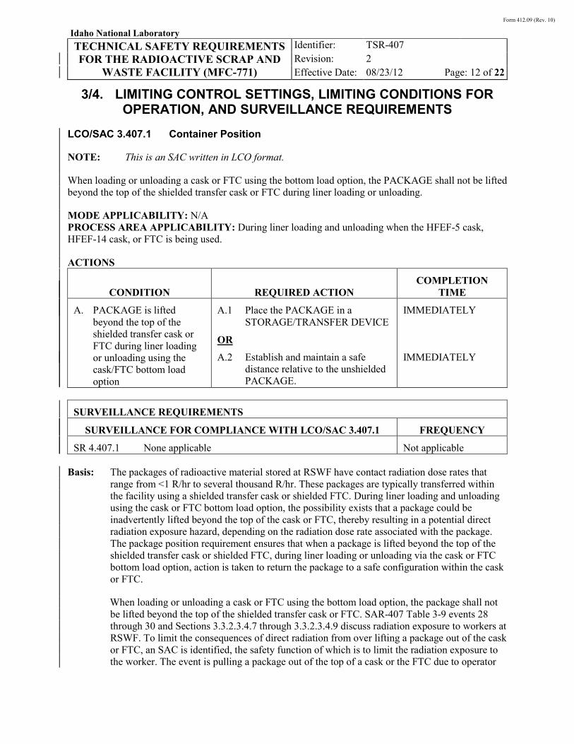
Form 412.09 (Rev. 10)
Idaho National Laboratory
TECHNICAL SAFETY REQUIREMENTS FOR THE RADIOACTIVE SCRAP AND
WASTE FACILITY (MFC-771)
Identifier: Revision: Effective Date:
TSR-407 2 08/23/12 Page: 12 of 22
3/4. LIMITING CONTROL SETTINGS, LIMITING CONDITIONS FOR OPERATION, AND SURVEILLANCE REQUIREMENTS
LCO/SAC 3.407.1 Container Position
NOTE: This is an SAC written in LCO format.
When loading or unloading a cask or FTC using the bottom load option, the PACKAGE shall not be lifted beyond the top of the shielded transfer cask or FTC during liner loading or unloading.
MODE APPLICABILITY: N/A PROCESS AREA APPLICABILITY: During liner loading and unloading when the HFEF-5 cask, HFEF-14 cask, or FTC is being used.
ACTIONS
CONDITION REQUIRED ACTION COMPLETION
TIME
A. PACKAGE is lifted beyond the top of the shielded transfer cask or FTC during liner loading or unloading using the cask/FTC bottom load option
A.1 Place the PACKAGE in a STORAGE/TRANSFER DEVICE
A.2 Establish and maintain a safe distance relative to the unshielded PACKAGE.
OR
IMMEDIATELY
IMMEDIATELY
SURVEILLANCE REQUIREMENTS
SURVEILLANCE FOR COMPLIANCE WITH LCO/SAC 3.407.1 FREQUENCY
SR 4.407.1 None applicable Not applicable Basis: The packages of radioactive material stored at RSWF have contact radiation dose rates that
range from <1 R/hr to several thousand R/hr. These packages are typically transferred within the facility using a shielded transfer cask or shielded FTC. During liner loading and unloading using the cask or FTC bottom load option, the possibility exists that a package could be inadvertently lifted beyond the top of the cask or FTC, thereby resulting in a potential direct radiation exposure hazard, depending on the radiation dose rate associated with the package. The package position requirement ensures that when a package is lifted beyond the top of the shielded transfer cask or shielded FTC, during liner loading or unloading via the cask or FTC bottom load option, action is taken to return the package to a safe configuration within the cask or FTC.
When loading or unloading a cask or FTC using the bottom load option, the package shall not be lifted beyond the top of the shielded transfer cask or FTC. SAR-407 Table 3-9 events 28 through 30 and Sections 3.3.2.3.4.7 through 3.3.2.3.4.9 discuss radiation exposure to workers at RSWF. To limit the consequences of direct radiation from over lifting a package out of the cask or FTC, an SAC is identified, the safety function of which is to limit the radiation exposure to the worker. The event is pulling a package out of the top of a cask or the FTC due to operator

Form 412.09 (Rev. 10)
Idaho National Laboratory
TECHNICAL SAFETY REQUIREMENTS FOR THE RADIOACTIVE SCRAP AND
WASTE FACILITY (MFC-771)
Identifier: Revision: Effective Date:
TSR-407 2 08/23/12 Page: 13 of 22
error (e.g., failure to stop the crane hoist while lifting the package) and/or equipment failure (e.g., failure of the crane hoist switch or failure of the motor shutoff switch). The potential for direct radiation exposure to a worker from the top of the HFEF-5 or HFEF-14 cask or FTC is lower compared to a bottom loading and unloading event, since potential exposure exists near the worker’s feet and legs in that case. By planning a recovery action for an over lifting event, the dose to the worker will be lower.
Action statements restore the package to a shielded configuration. Action statements for conditions outside this SAC state:
• Place the package back into an RSWF storage/transfer device
• Establish and maintain a safe distance relative to the package.
LCO/SAC 3.407.2 Supplemental Radiological Control
NOTE: This is an SAC written in LCO format.
Temporary shielding shall be installed, or other mitigative measures (distance, time, etc.), to maintain the direct radiation exposure rate below 5 R/hr during liner loading or unloading operations involving a shielded transfer cask or shielded FTC or ISC.
MODE APPLICABILITY: N/A PROCESS AREA APPLICABILITY: RSWF liner array.
ACTIONS
CONDITION REQUIRED ACTION COMPLETION
TIME
A. Dose rate exceeds 5 R/hr A.1. Place the PACKAGE in a STORAGE TRANSFER/DEVICE.
A.2 Establish and maintain a safe distance relative to the PACKAGE.
OR
IMMEDIATELY
IMMEDIATELY
SURVEILLANCE REQUIREMENTS
SURVEILLANCE FOR COMPLIANCE WITH LCO/SAC 3.407.2 FREQUENCY
SR 4.407.2 None applicable. Not applicable

Form 412.09 (Rev. 10)
Idaho National Laboratory
TECHNICAL SAFETY REQUIREMENTS FOR THE RADIOACTIVE SCRAP AND
WASTE FACILITY (MFC-771)
Identifier: Revision: Effective Date:
TSR-407 2 08/23/12 Page: 14 of 22
Basis: Temporary shielding shall be installed, or other mitigative measures (distance, time, etc.), to maintain the direct radiation exposure rate below 5 R/hr during operations involving a shielded transfer cask or shielded FTC or ISC. SAR-407 Table 3-9 events 22 through 39 and Section 3.3.2.3.4 discuss direct radiation exposure hazards at RSWF. To limit the consequences of radiation exposure during liner loading or unloading, an SAC is identified, the safety function of which is to limit the direct radiation exposure to the worker.
The containers of radioactive material stored at RSWF have contact radiation dose rates that can range from <1 R/hr to several thousand R/hr. These containers are typically transferred within the facility using a storage/transfer device. To support the transfer of a container between the cask and liner, a steel positioning device is placed on/over the liner, and the cask is then set upon the positioning device. Although the positioning device provides shielding from the direct radiation hazard when the container is between the cask and soil, the device does not completely eliminate the existence of gaps between the cask and the soil. Such gaps may pose a pathway for streaming radiation during the time the container is between the soil and the cask. High radiation may also result from bottom loading the FTC or the use of the ISC, which does not have lead shielding in the concrete structure.
Continuously monitoring the radiation dose rate in the vicinity of the closest worker(s) ensures the ability to take prompt action if an unexpectedly high direct radiation dose is encountered. Temporary shielding shall be installed, or other mitigative measures established, to mitigate the streaming radiation hazard. The amount of temporary shielding used, or the type/extent of other mitigative measures established, may vary, depending upon the radiation hazard associated with the container being handled, the positioning device being used, and the gap between the positioning device and the soil. This SAC requires that temporary shielding be installed, or other mitigative measures established, during liner loading and unloading operations to maintain direct radiation exposure rates below 5 R/hr. In addition, actions are provided in the event that the dose rate exceeds 5 R/hr.
Action statements restore the package to a safe dose rate for worker protection. Action statements for conditions outside this SAC state:
• Place the package back into a storage/transfer device
• Establish and maintain a safe distance relative to the package.
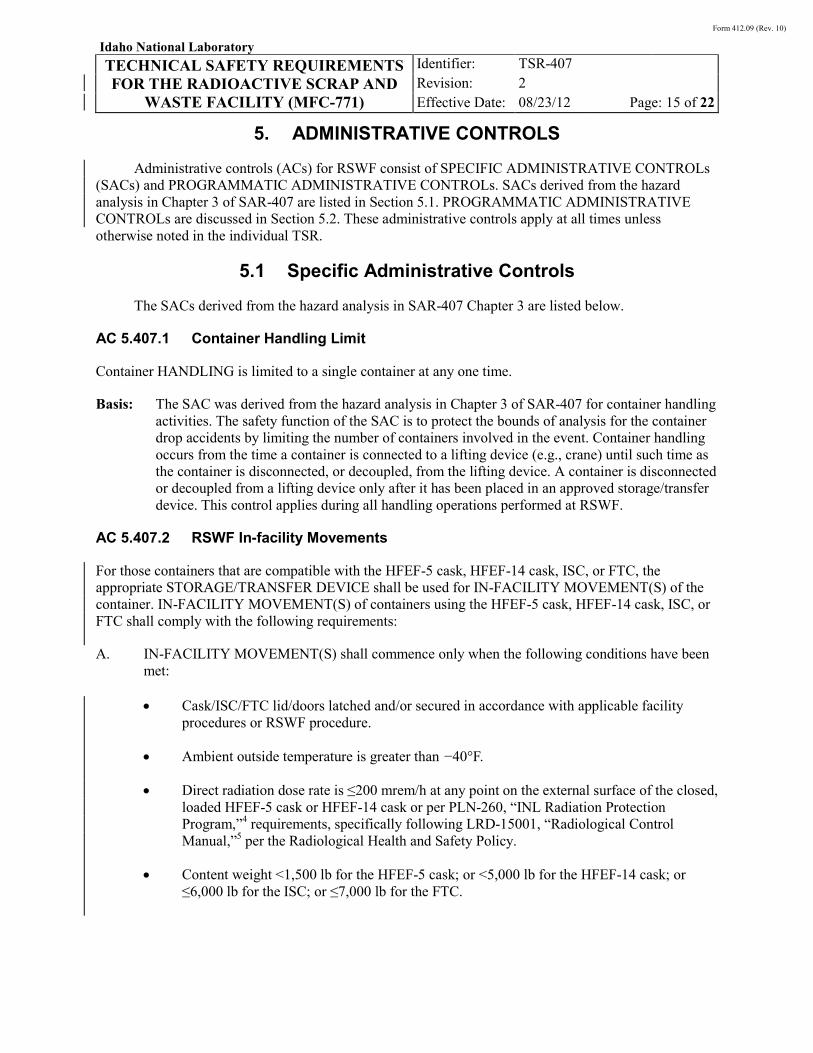
Form 412.09 (Rev. 10)
Idaho National Laboratory
TECHNICAL SAFETY REQUIREMENTS FOR THE RADIOACTIVE SCRAP AND
WASTE FACILITY (MFC-771)
Identifier: Revision: Effective Date:
TSR-407 2 08/23/12 Page: 15 of 22
5. ADMINISTRATIVE CONTROLS
Administrative controls (ACs) for RSWF consist of SPECIFIC ADMINISTRATIVE CONTROLs (SACs) and PROGRAMMATIC ADMINISTRATIVE CONTROLs. SACs derived from the hazard analysis in Chapter 3 of SAR-407 are listed in Section 5.1. PROGRAMMATIC ADMINISTRATIVE CONTROLs are discussed in Section 5.2. These administrative controls apply at all times unless otherwise noted in the individual TSR.
5.1 Specific Administrative Controls
The SACs derived from the hazard analysis in SAR-407 Chapter 3 are listed below.
AC 5.407.1 Container Handling Limit
Container HANDLING is limited to a single container at any one time.
Basis: The SAC was derived from the hazard analysis in Chapter 3 of SAR-407 for container handling activities. The safety function of the SAC is to protect the bounds of analysis for the container drop accidents by limiting the number of containers involved in the event. Container handling occurs from the time a container is connected to a lifting device (e.g., crane) until such time as the container is disconnected, or decoupled, from the lifting device. A container is disconnected or decoupled from a lifting device only after it has been placed in an approved storage/transfer device. This control applies during all handling operations performed at RSWF.
AC 5.407.2 RSWF In-facility Movements
For those containers that are compatible with the HFEF-5 cask, HFEF-14 cask, ISC, or FTC, the appropriate STORAGE/TRANSFER DEVICE shall be used for IN-FACILITY MOVEMENT(S) of the container. IN-FACILITY MOVEMENT(S) of containers using the HFEF-5 cask, HFEF-14 cask, ISC, or FTC shall comply with the following requirements:
A. IN-FACILITY MOVEMENT(S) shall commence only when the following conditions have been met:
• Cask/ISC/FTC lid/doors latched and/or secured in accordance with applicable facility procedures or RSWF procedure.
• Ambient outside temperature is greater than −40°F.
• Direct radiation dose rate is ≤200 mrem/h at any point on the external surface of the closed, loaded HFEF-5 cask or HFEF-14 cask or per PLN-260, “INL Radiation Protection Program,”4 requirements, specifically following LRD-15001, “Radiological Control Manual,”5 per the Radiological Health and Safety Policy.
• Content weight <1,500 lb for the HFEF-5 cask; or <5,000 lb for the HFEF-14 cask; or ≤6,000 lb for the ISC; or ≤7,000 lb for the FTC.
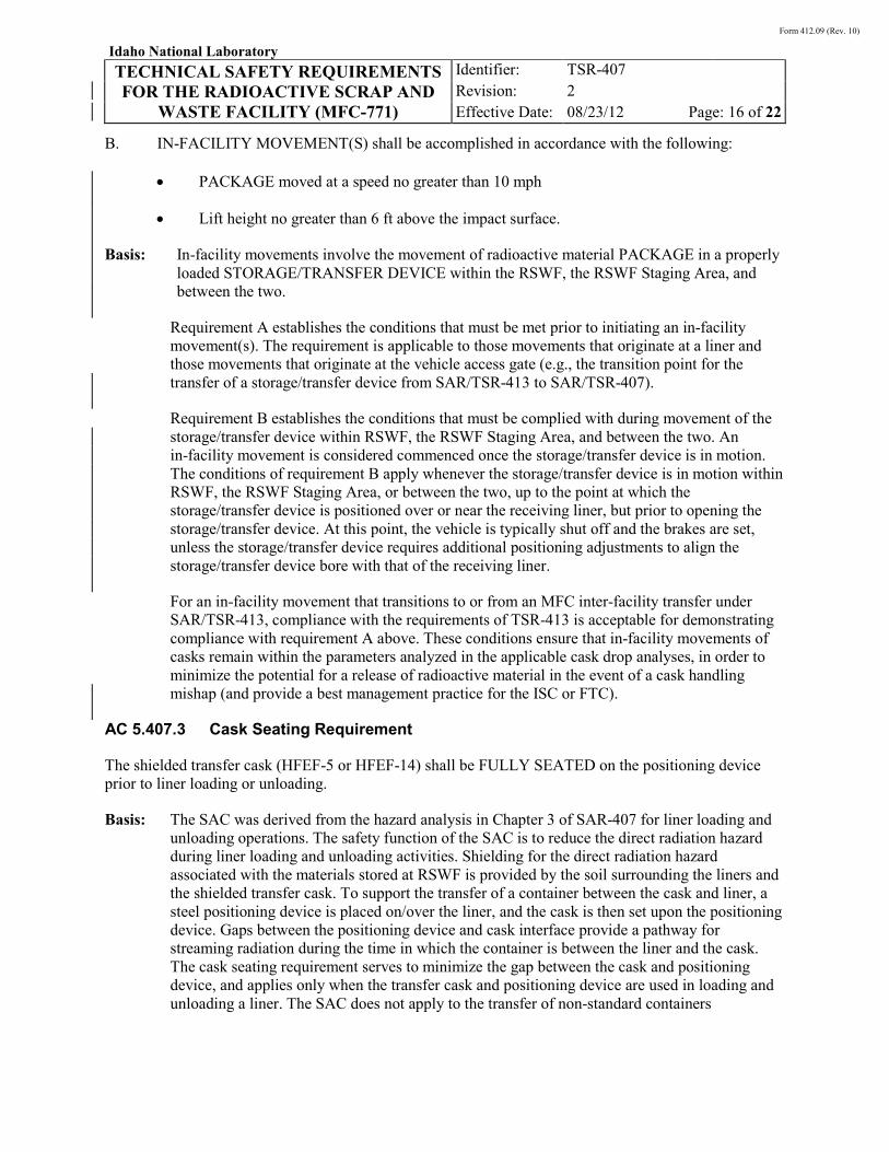
Form 412.09 (Rev. 10)
Idaho National Laboratory
TECHNICAL SAFETY REQUIREMENTS FOR THE RADIOACTIVE SCRAP AND
WASTE FACILITY (MFC-771)
Identifier: Revision: Effective Date:
TSR-407 2 08/23/12 Page: 16 of 22
B. IN-FACILITY MOVEMENT(S) shall be accomplished in accordance with the following:
• PACKAGE moved at a speed no greater than 10 mph
• Lift height no greater than 6 ft above the impact surface.
Basis: In-facility movements involve the movement of radioactive material PACKAGE in a properly loaded STORAGE/TRANSFER DEVICE within the RSWF, the RSWF Staging Area, and between the two.
Requirement A establishes the conditions that must be met prior to initiating an in-facility movement(s). The requirement is applicable to those movements that originate at a liner and those movements that originate at the vehicle access gate (e.g., the transition point for the transfer of a storage/transfer device from SAR/TSR-413 to SAR/TSR-407).
Requirement B establishes the conditions that must be complied with during movement of the storage/transfer device within RSWF, the RSWF Staging Area, and between the two. An in-facility movement is considered commenced once the storage/transfer device is in motion. The conditions of requirement B apply whenever the storage/transfer device is in motion within RSWF, the RSWF Staging Area, or between the two, up to the point at which the storage/transfer device is positioned over or near the receiving liner, but prior to opening the storage/transfer device. At this point, the vehicle is typically shut off and the brakes are set, unless the storage/transfer device requires additional positioning adjustments to align the storage/transfer device bore with that of the receiving liner.
For an in-facility movement that transitions to or from an MFC inter-facility transfer under SAR/TSR-413, compliance with the requirements of TSR-413 is acceptable for demonstrating compliance with requirement A above. These conditions ensure that in-facility movements of casks remain within the parameters analyzed in the applicable cask drop analyses, in order to minimize the potential for a release of radioactive material in the event of a cask handling mishap (and provide a best management practice for the ISC or FTC).
AC 5.407.3 Cask Seating Requirement
The shielded transfer cask (HFEF-5 or HFEF-14) shall be FULLY SEATED on the positioning device prior to liner loading or unloading.
Basis: The SAC was derived from the hazard analysis in Chapter 3 of SAR-407 for liner loading and unloading operations. The safety function of the SAC is to reduce the direct radiation hazard during liner loading and unloading activities. Shielding for the direct radiation hazard associated with the materials stored at RSWF is provided by the soil surrounding the liners and the shielded transfer cask. To support the transfer of a container between the cask and liner, a steel positioning device is placed on/over the liner, and the cask is then set upon the positioning device. Gaps between the positioning device and cask interface provide a pathway for streaming radiation during the time in which the container is between the liner and the cask. The cask seating requirement serves to minimize the gap between the cask and positioning device, and applies only when the transfer cask and positioning device are used in loading and unloading a liner. The SAC does not apply to the transfer of non-standard containers

Form 412.09 (Rev. 10)
Idaho National Laboratory
TECHNICAL SAFETY REQUIREMENTS FOR THE RADIOACTIVE SCRAP AND
WASTE FACILITY (MFC-771)
Identifier: Revision: Effective Date:
TSR-407 2 08/23/12 Page: 17 of 22
(e.g., nuclide traps, cold trap, etc.). The SAC does not prohibit the use of temporary shielding, in conjunction with the positioning device, during liner loading and unloading activities.
AC 5.407.4 Staffing Requirement
At least one QUALIFIED operator or Shift Supervisor shall be present during liner loading and unloading operations involving a shielded transfer cask.
Basis: This SAC was derived from the hazard analysis in Chapter 3 of SAR-407 for container position requirement and cask positioning device seating, during liner loading and unloading operations. The safety function of this SAC is to reduce the likelihood of a radioactive material container from being inadvertently lifted out the top of a shielded transfer cask during liner loading and unloading activities. The safety function of this SAC also ensures proper seating of the cask on the positioning device prior to liner loading and unloading activities. The SAC assures that qualified operations personnel are available at the facility to confirm cask seating required in AC 5.407.3 and the container position specified in LCO/SAC 3.407.1
NOTE: This staffing requirement is not applicable during emergency evacuation of RSWF.
AC 5.407. 5 Soil Excavation Control
Soil excavation shall be evaluated and appropriate radiation protection controls and monitoring established, prior to commencement of soil excavation operations within RSWF.
Basis: This SAC was derived from the hazard analysis in Chapter 3 of SAR-407 for activities involving soil excavation within the facility. The safety function of this SAC is to prevent direct radiation exposure resulting from the intentional removal of excessive soil from around the liners through use of heavy equipment or other similar means, such as during liner retrieval, anode replacement, and liner installation. This control is not applicable to routine or periodic soil maintenance activities, or similar operations, that result in soil disturbance near the top of the liners. The soil in which the liners are located provides shielding from the radiation hazard associated with the radioactive material stored therein. Soil excavation, laterally or vertically, can result in a reduction or elimination of the shielding function provided by the soil. In the absence of engineered shielding features, the soil excavation requirement serves to prevent direct radiation exposure during soil removal through proper evaluation and control.
AC 5.407.6 Criticality Safety Controls
The nuclear criticality safety controls specific to the operations and activities conducted at RSWF shall comply with the following requirements.
A. FISSIONABLE MATERIAL storage and HANDLING
• Approved FISSIONABLE MATERIAL storage and handling configurations with the following details, as applicable
. FISSIONABLE MATERIAL storage and HANDLING shall be conducted in accordance with a contractor-approved list that establishes specific limits for controlled parameters as derived from applicable criticality safety evaluations (CSEs). The contractor-approved list that addresses FISSIONABLE MATERIAL storage and HANDLING shall provide the following specific details:

Form 412.09 (Rev. 10)
Idaho National Laboratory
TECHNICAL SAFETY REQUIREMENTS FOR THE RADIOACTIVE SCRAP AND
WASTE FACILITY (MFC-771)
Identifier: Revision: Effective Date:
TSR-407 2 08/23/12 Page: 18 of 22
o FISSIONABLE MATERIAL quantity (mass or item)
o FISSIONABLE MATERIAL configuration and/or PACKAGE requirements
o Liner and cask limits
• Applicable CSEs.
B. RSWF liners shall be installed with sufficient spacing, at least 4 in., between adjacent liners.
Basis: This SAC was derived from the criticality safety portion of the hazard analysis, which is addressed in Chapter 6 of SAR-407. As documented in Chapter 6 of SAR-407, CSEs have been performed to determine the controlled parameters, and limits thereof, necessary to ensure critically safe operations. This SAC includes those controls applied to parameters or conditions, as derived from the criticality safety analysis, which must be violated or exceeded before a criticality is possible. The safety function of this SAC is criticality accident prevention. The RSWF nuclear criticality controls address criticality accident scenarios that pertain to fissionable material storage and fissionable material handling. In both cases, criticality occurs due to the presence of excess fissionable material, the presence of a significant quantity of moderator (water), and/or fissionable material reconfiguration (e.g., catastrophic can failure).
Documentation of the specific details of the fissionable material storage and handling controls in a contractor-approved list ensures that only those configurations and/or circumstances that have been properly analyzed arise in facility operations. The required details of the contractor-approved list are defined in the TSR SAC wording, and address fissionable material mass or item, configuration and/or package requirements. The TSR SAC also requires that the source CSE(s) be identified in the contractor-approved list. These CSEs include those cited in Chapter 6 of SAR-407 to establish the initial criticality safety boundary of the facility or other CSEs specifically developed as the technical basis for additions to the contractor-approved list.
5.2 Programmatic Administrative Controls
PROGRAMMATIC ADMINISTRATIVE CONTROLs can either be general controls or facility-specific controls. General programmatic controls for INL NUCLEAR FACILITIES that are applicable to RSWF operations are provided in TSR-400.2 The TSRs from TSR-400 that were explicitly selected in the RSWF hazard and accident analyses in Chapter 3 of SAR-407 include the following:
• Radiation protection program (implements 10 CFR 835)
• Emergency preparedness program (AC 5.400.9)
• Hoisting and rigging program (AC 5.400.12).
No facility-specific programmatic controls were derived for RSWF operations from the hazard and accident analyses in Chapter 3 of SAR-407.

Form 412.09 (Rev. 10)
Idaho National Laboratory
TECHNICAL SAFETY REQUIREMENTS FOR THE RADIOACTIVE SCRAP AND
WASTE FACILITY (MFC-771)
Identifier: Revision: Effective Date:
TSR-407 2 08/23/12 Page: 19 of 22
6. DESIGN FEATURES
Design features are those passive design features of a NUCLEAR FACILITY that, if altered or modified, would have a significant effect on safe operation. Design features have been previously identified from the RSWF hazard analysis (see Chapter 3 of SAR-407) as safety-class or safety-significant SSCs. RSWF passive design features are identified below; described in SAR-407, Chapter 4; and listed in Section 5.6 of SAR-407.
Safety-class SSCs
No safety-class SSCs were derived from the RSWF hazard analysis.
Safety-significant SSCs
1. HFEF-5 and HFEF-14 shielded transfer casks.
All modifications to the passive design features listed above are subject to the TSR-level configuration management program requirements (AC 5.400.10) and the unreviewed safety question (USQ) process.
Form 412.09 (Rev. 10)
Idaho National Laboratory
TECHNICAL SAFETY REQUIREMENTS FOR THE RADIOACTIVE SCRAP AND
WASTE FACILITY (MFC-771)
Identifier: Revision: Effective Date:
TSR-407 2 08/23/12 Page: 20 of 22
7. REFERENCES
1. 10 CFR 830, Subpart B, “Safety Basis Requirements,” Code of Federal Regulations, Office of the Federal Register, January 1, 2005.
2. TSR-400, “INL Standardized Technical Safety Requirements,” current revision.
3. SAR-407, “Safety Analysis Report for the Radioactive Scrap and Waste Facility (MFC-771),” current revision.
4. PLN-260, “INL Radiation Protection Program,” current revision.
5. LRD-15001, “Radiological Control Manual,” current revision.

Form 412.09 (Rev. 10)
Idaho National Laboratory
TECHNICAL SAFETY REQUIREMENTS FOR THE RADIOACTIVE SCRAP AND
WASTE FACILITY (MFC-771)
Identifier: Revision: Effective Date:
TSR-407 2 08/23/12 Page: 21 of 22
Appendix A
Appendix A
TSR Bases Discussion
This section of the TSR document provides summary statements of the technical basis for the SLs, LCSs, and LCOs and their associated SRs, and shows how the numeric values, conditions, surveillances, and action statements fulfill the purpose derived from the hazard and accident analysis in the facility-specific SAR.
Safety Limits (SLs)
There are no SLs for RSWF operations; therefore, an associated bases discussion is not provided.
Limiting Control Settings (LCSs)
There are no LSCs for RSWF operations; therefore, an associated bases discussion is not provided.
Limiting Conditions for Operation (LCOs)
There are two LCO/SACs for RSWF operations.
Form 412.09 (Rev. 10)
Idaho National Laboratory
TECHNICAL SAFETY REQUIREMENTS FOR THE RADIOACTIVE SCRAP AND
WASTE FACILITY (MFC-771)
Identifier: Revision: Effective Date:
TSR-407 2 08/23/12 Page: 22 of 22
Appendix A
INTENTIONALLY BLANK

The INL is a U.S. Department of Energy National Laboratory operated by Battelle Energy Alliance.
TSR RELATED Document ID: LST-587Revision ID: 3
Effective Date: 10/22/14
List
SAR-407 and TSR-407 Nuclear Safety Basis Implementation Matrix

INTENTIONALLY BLANK
Form 412.09 (Rev. 09)
Idaho National Laboratory SAR-407 AND TSR-407 NUCLEAR
SAFETY BASIS IMPLEMENTATION MATRIX
Identifier: Revision: Effective Date:
LST-587
3
10/22/14 Page: 3 of 16
Materials and Fuels Complex List For Additional Info: http://EDMS eCR Number: 618926 Manual: MFC RSWF Nuclear Safety Basis (LST, DSA)
REVISION LOG
Rev. Date Affected Pages Revision Description
0 06/11/09 All See eCR 569795. New issue.
1 08/23/12 All See eCR 607009. Revision.
2 10/29/12 All See eCR 608425. Revision.
3 10/22/14 All See eCR 618926. Revision.

Form 412.09 (Rev. 09)
Idaho National Laboratory SAR-407 AND TSR-407 NUCLEAR
SAFETY BASIS IMPLEMENTATION MATRIX
Identifier: Revision: Effective Date:
LST-587
3
10/22/14 Page: 4 of 16
INTENTIONALLY BLANK

Form 412.09 (Rev. 09)
Idaho National Laboratory SAR-407 AND TSR-407 NUCLEAR
SAFETY BASIS IMPLEMENTATION MATRIX
Identifier: Revision: Effective Date:
LST-587
3
10/22/14 Page: 5 of 16
CONTENTS
1. PURPOSE ............................................................................................................................7
2. SCOPE .................................................................................................................................7
3. RESPONSIBILITIES ..........................................................................................................7
4. LIST .....................................................................................................................................8
4.1 Implementation Matrix ............................................................................................8
4.2 Conditions of Approval for SAR/TSR-407 ...........................................................15
5. REFERENCES ..................................................................................................................16

Form 412.09 (Rev. 09)
Idaho National Laboratory SAR-407 AND TSR-407 NUCLEAR
SAFETY BASIS IMPLEMENTATION MATRIX
Identifier: Revision: Effective Date:
LST-587
3
10/22/14 Page: 6 of 16
INTENTIONALLY BLANK

Form 412.09 (Rev. 09)
Idaho National Laboratory SAR-407 AND TSR-407 NUCLEAR
SAFETY BASIS IMPLEMENTATION MATRIX
Identifier: Revision: Effective Date:
LST-587
3
10/22/14 Page: 7 of 16
1. PURPOSE
To identify all SAR-407, “Safety Analysis Report for the Radioactive Scrap and Waste Facility (MFC-771),” and TSR-407, “Technical Safety Requirements for the Radioactive Scrap and Waste Facility (MFC-771),” requirements and to identify which documents implement those requirements. As applicable, this list also identifies implementation of Department of Energy (DOE) conditions of approval (COAs) for the facility.
2. SCOPE
This list is an aid to identify documents that require application of the unreviewed safety question (USQ) process.
3. RESPONSIBILITIES
Nuclear Facility Manager
The nuclear facility manager (NFM) is responsible for implementation of these nuclear safety basis requirements as delineated by the list of implementing documents. The NFM is responsible to ensure compliance with the documents that implement these requirements.
Implementing Document Owner
The implementing document owners are responsible to ensure that a systematic review (via the USQ process in accordance with LWP-10801, “INL Unreviewed Safety Questions”) is performed for proposed changes to the implementing documents identified in Section 4.
As consolidated procedures are developed and implemented, the Electronic Document Management System (EDMS) is used to clearly identify documents that have been replaced or superseded by equivalent consolidated documents. The implementing document owners are responsible to ensure proposed changes to such equivalent documents receive a systematic review via LWP-10801 prior to revision.

Form 412.09 (Rev. 09)
Idaho National Laboratory SAR-407 AND TSR-407 NUCLEAR
SAFETY BASIS IMPLEMENTATION MATRIX
Identifier: Revision: Effective Date:
LST-587
3
10/22/14 Page: 8 of 16
4. LIST
4.1 Implementation Matrix
Specification
Number SpecificationImplementing Document(s)
1. TSR-407 LCO/SAC 3.407.1
Container Position
NOTE: This is an SAC written in LCO format.
When loading or unloading a cask or FTC using the bottom load option, the PACKAGE shall not be lifted beyond the top of the shielded transfer cask or FTC during liner loading or unloading.
MODE APPLICABILITY: N/A
PROCESS AREA APPLICABILITY: During liner loading and unloading when the HFEF-5 cask, HFEF-14 cask, or FTC is being used.
ACTIONS
CONDITION REQUIRED ACTION COMPLETION TIME
A. PACKAGE is lifted beyond the top of the shielded transfer cask or FTC during liner loading or unloading using the cask/FTC bottom load option.
A.1. Place the PACKAGE in a STORAGE TRANSFER/DEVICE.
IMMEDIATELY
OR
A.2 Establish and maintain a safe distance relative to the PACKAGE.
IMMEDIATELY
SURVEILLANCE REQUIREMENTS
SURVEILLANCE FOR COMPLIANCE WITH LCO/SAC 3.407.1 FREQUENCY
SR 4.407.1 None applicable. Not applicable
RSWF-OI-001 RSWF-OI-002
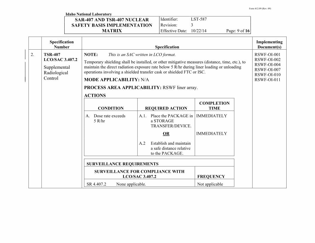
Form 412.09 (Rev. 09)
Idaho National Laboratory SAR-407 AND TSR-407 NUCLEAR
SAFETY BASIS IMPLEMENTATION MATRIX
Identifier: Revision: Effective Date:
LST-587
3
10/22/14 Page: 9 of 16
Specification
Number SpecificationImplementing Document(s)
2. TSR-407 LCO/SAC 3.407.2
Supplemental Radiological Control
NOTE: This is an SAC written in LCO format.
Temporary shielding shall be installed, or other mitigative measures (distance, time, etc.), to maintain the direct radiation exposure rate below 5 R/hr during liner loading or unloading operations involving a shielded transfer cask or shielded FTC or ISC.
MODE APPLICABILITY: N/A
PROCESS AREA APPLICABILITY: RSWF liner array.
ACTIONS
CONDITION REQUIRED ACTION COMPLETION
TIME
A. Dose rate exceeds 5 R/hr
A.1. Place the PACKAGE in a STORAGE TRANSFER/DEVICE.
IMMEDIATELY
OR IMMEDIATELY
A.2 Establish and maintain a safe distance relative to the PACKAGE.
SURVEILLANCE REQUIREMENTS
SURVEILLANCE FOR COMPLIANCE WITH LCO/SAC 3.407.2 FREQUENCY
SR 4.407.2 None applicable. Not applicable
RSWF-OI-001 RSWF-OI-002 RSWF-OI-004 RSWF-OI-007 RSWF-OI-010 RSWF-OI-011
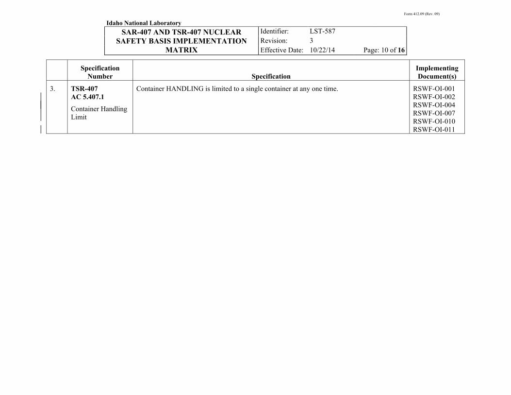
Form 412.09 (Rev. 09)
Idaho National Laboratory SAR-407 AND TSR-407 NUCLEAR
SAFETY BASIS IMPLEMENTATION MATRIX
Identifier: Revision: Effective Date:
LST-587
3
10/22/14 Page: 10 of 16
Specification
Number SpecificationImplementing Document(s)
3. TSR-407 AC 5.407.1
Container Handling Limit
Container HANDLING is limited to a single container at any one time. RSWF-OI-001 RSWF-OI-002 RSWF-OI-004 RSWF-OI-007 RSWF-OI-010 RSWF-OI-011
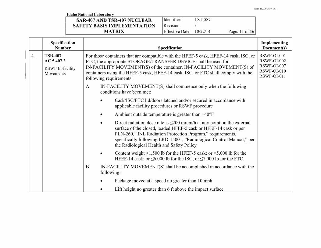
Form 412.09 (Rev. 09)
Idaho National Laboratory SAR-407 AND TSR-407 NUCLEAR
SAFETY BASIS IMPLEMENTATION MATRIX
Identifier: Revision: Effective Date:
LST-587
3
10/22/14 Page: 11 of 16
Specification
Number SpecificationImplementing Document(s)
4. TSR-407 AC 5.407.2
RSWF In-facility Movements
For those containers that are compatible with the HFEF-5 cask, HFEF-14 cask, ISC, or FTC, the appropriate STORAGE/TRANSFER DEVICE shall be used for IN-FACILITY MOVEMENT(S) of the container. IN-FACILITY MOVEMENT(S) of containers using the HFEF-5 cask, HFEF-14 cask, ISC, or FTC shall comply with the following requirements:
A. IN-FACILITY MOVEMENT(S) shall commence only when the following conditions have been met:
• Cask/ISC/FTC lid/doors latched and/or secured in accordance with applicable facility procedures or RSWF procedure
• Ambient outside temperature is greater than −40°F
• Direct radiation dose rate is ≤200 mrem/h at any point on the external surface of the closed, loaded HFEF-5 cask or HFEF-14 cask or per PLN-260, “INL Radiation Protection Program,” requirements, specifically following LRD-15001, “Radiological Control Manual,” per the Radiological Health and Safety Policy
• Content weight <1,500 lb for the HFEF-5 cask; or <5,000 lb for the HFEF-14 cask; or ≤6,000 lb for the ISC; or ≤7,000 lb for the FTC.
B. IN-FACILITY MOVEMENT(S) shall be accomplished in accordance with the following:
• Package moved at a speed no greater than 10 mph
• Lift height no greater than 6 ft above the impact surface.
RSWF-OI-001 RSWF-OI-002 RSWF-OI-007 RSWF-OI-010 RSWF-OI-011
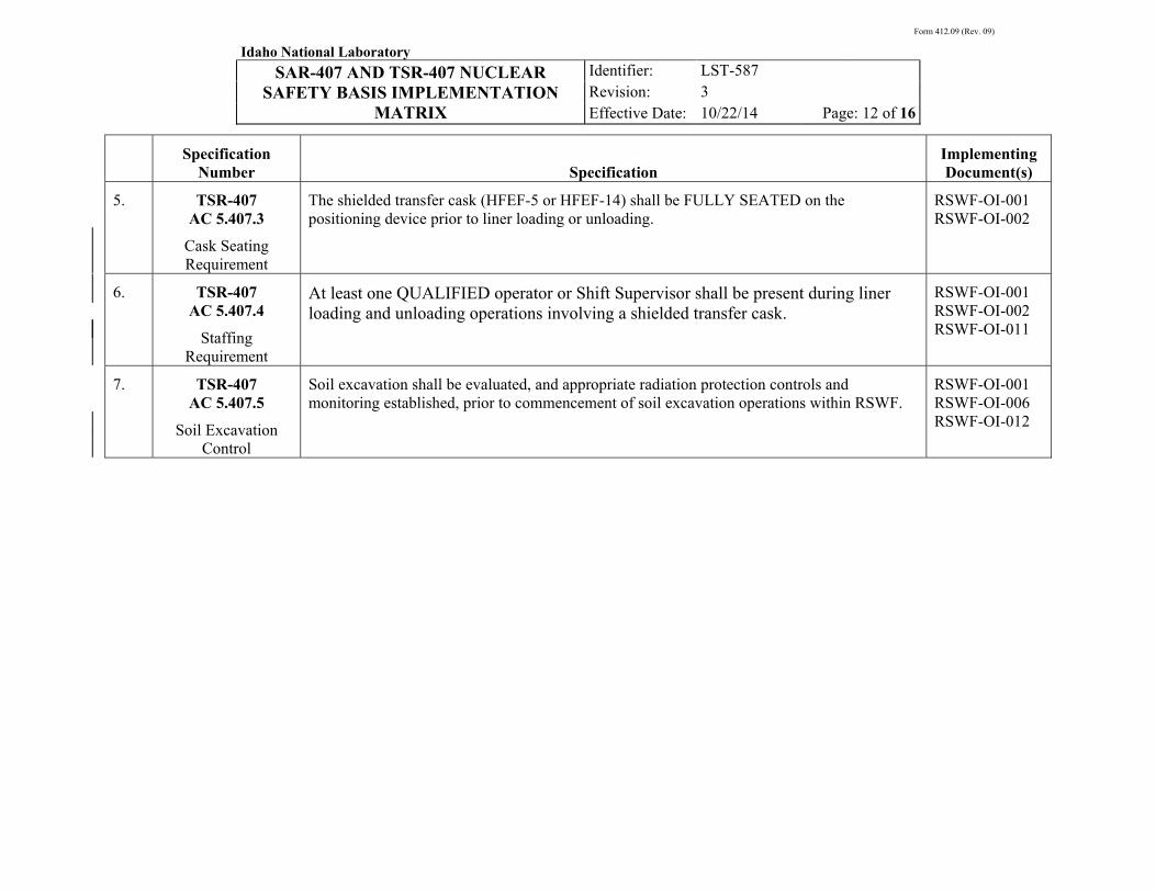
Form 412.09 (Rev. 09)
Idaho National Laboratory SAR-407 AND TSR-407 NUCLEAR
SAFETY BASIS IMPLEMENTATION MATRIX
Identifier: Revision: Effective Date:
LST-587
3
10/22/14 Page: 12 of 16
Specification
Number SpecificationImplementing Document(s)
5. TSR-407 AC 5.407.3
Cask Seating Requirement
The shielded transfer cask (HFEF-5 or HFEF-14) shall be FULLY SEATED on the positioning device prior to liner loading or unloading.
RSWF-OI-001 RSWF-OI-002
6. TSR-407 AC 5.407.4
Staffing Requirement
At least one QUALIFIED operator or Shift Supervisor shall be present during liner loading and unloading operations involving a shielded transfer cask.
RSWF-OI-001 RSWF-OI-002 RSWF-OI-011
7. TSR-407 AC 5.407.5
Soil Excavation Control
Soil excavation shall be evaluated, and appropriate radiation protection controls and monitoring established, prior to commencement of soil excavation operations within RSWF.
RSWF-OI-001 RSWF-OI-006 RSWF-OI-012

Form 412.09 (Rev. 09)
Idaho National Laboratory SAR-407 AND TSR-407 NUCLEAR
SAFETY BASIS IMPLEMENTATION MATRIX
Identifier: Revision: Effective Date:
LST-587
3
10/22/14 Page: 13 of 16
Specification
Number SpecificationImplementing Document(s)
8. TSR-407 AC 5.407.6
Criticality Safety Controls
The nuclear criticality safety controls specific to the operations and activities conducted at RSWF shall comply with the following requirements.
A. FISSIONABLE MATERIAL storage and HANDLING. FISSIONABLE MATERIAL storage and handling shall be conducted in accordance with a contractor-approved list that establishes specific limits for controlled parameters as derived from applicable criticality safety evaluations (CSEs). The contractor-approved list that addresses FISSIONABLE MATERIAL storage and handling shall provide the following specific details:
Approved FISSIONABLE MATERIAL storage and handling configurations with the following details, as applicable
• FISSIONABLE MATERIAL quantity (mass or item)
• FISSIONABLE MATERIAL configuration and/or PACKAGE requirements
• Applicable CSEs
B. RSWF liners shall be installed with sufficient spacing, at least 4 inches, between adjacent liners.
RSWF-OI-001 RSWF-OI-003 RSWF-OI-007 RSWF-OI-010 RSWF-OI-011 LST-391
9. SAR-407 Section 3.3.2.3.1.1
Also, RSWF and the area immediately surrounding the facility are typically maintained vegetation-free.
RSWF-OI-006

Form 412.09 (Rev. 09)
Idaho National Laboratory SAR-407 AND TSR-407 NUCLEAR
SAFETY BASIS IMPLEMENTATION MATRIX
Identifier: Revision: Effective Date:
LST-587
3
10/22/14 Page: 14 of 16
Specification
Number SpecificationImplementing Document(s)
10. SAR-407 Section 3.3.2.3.1.6
Remote liner drilling (safety analysis commitment).
The remote liner drilling commitment reduces the consequences of a radioactive material release to the facility worker by removing the facility worker from the potential hazard during initial opening (drilling) of a closed liner.
Remote liner drilling involves the use of a drilling apparatus designed to be operated several feet from the liner.
RSWF-OI-002
11. SAR-407 Section 3.3.2.3.1.6
Liner purging/venting (safety analysis commitment).
The liner purging/venting commitment reduces the likelihood of a hydrogen explosion/fire by purging a liner with an inert gas, or by passively venting a liner, after vent/purge tap(s) have been installed using the remote liner drilling system, but prior to opening/cutting the liner.
When liners are passively vented, sampling of the liner atmosphere is performed to confirm the absence of a potentially flammable gas mixture prior to cutting/opening.
RSWF-OI-002
12. SAR-407 Section 3.3.2.3.1.6
The remote liner drilling and liner purging/venting commitments apply to those liners that have welded closure covers.
RSWF-OI-002
13. SAR-407 Section 3.3.2.3.1.7
The storage configuration of packages within the RSWF liners is such that there is at least one level of containment that serves as a barrier between the radioactive material and the liner atmosphere.
RSWF-OI-001 RSWF-OI-003
14. SAR-407 Section 3.3.2.3.2.3
The containers handled at RSWF consist of a dual, nested, sealed container configuration (or other packaging configuration that provides at least double containment of radioactive material).
RSWF-OI-003
15. SAR-407 Section 3.3.2.3.2.6
Liner structural analysis (safety analysis commitment)… an analysis of the structural capability of the 16-, 24-, 26-, and 30-in. liners to withstand static and dynamic loads from soil and heavy equipment has been performed.
The procedural requirement to evaluate equipment being utilized near liners is completed in RSWF ECARs such as ECAR-1827, “RSWF Equipment Loading Adjacent to Liners.”
ECAR-1827
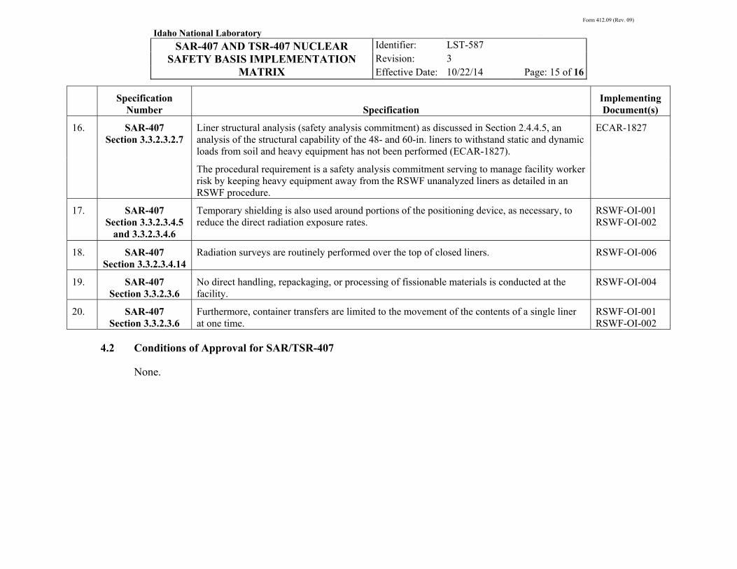
Form 412.09 (Rev. 09)
Idaho National Laboratory SAR-407 AND TSR-407 NUCLEAR
SAFETY BASIS IMPLEMENTATION MATRIX
Identifier: Revision: Effective Date:
LST-587
3
10/22/14 Page: 15 of 16
Specification
Number SpecificationImplementing Document(s)
16. SAR-407 Section 3.3.2.3.2.7
Liner structural analysis (safety analysis commitment) as discussed in Section 2.4.4.5, an analysis of the structural capability of the 48- and 60-in. liners to withstand static and dynamic loads from soil and heavy equipment has not been performed (ECAR-1827).
ECAR-1827
The procedural requirement is a safety analysis commitment serving to manage facility worker risk by keeping heavy equipment away from the RSWF unanalyzed liners as detailed in an RSWF procedure.
17. SAR-407 Section 3.3.2.3.4.5
and 3.3.2.3.4.6
Temporary shielding is also used around portions of the positioning device, as necessary, to reduce the direct radiation exposure rates.
RSWF-OI-001 RSWF-OI-002
18. SAR-407 Section 3.3.2.3.4.14
Radiation surveys are routinely performed over the top of closed liners. RSWF-OI-006
19. SAR-407 Section 3.3.2.3.6
No direct handling, repackaging, or processing of fissionable materials is conducted at the facility.
RSWF-OI-004
20. SAR-407 Section 3.3.2.3.6
Furthermore, container transfers are limited to the movement of the contents of a single liner at one time.
RSWF-OI-001 RSWF-OI-002
4.2 Conditions of Approval for SAR/TSR-407
None.

Form 412.09 (Rev. 09)
Idaho National Laboratory SAR-407 AND TSR-407 NUCLEAR
SAFETY BASIS IMPLEMENTATION MATRIX
Identifier: Revision: Effective Date:
LST-587
3
10/22/14 Page: 16 of 16
5. REFERENCES
LWP-10801, “INL Unreviewed Safety Questions”
SAR-407, “Safety Analysis Report for the Radioactive Scrap and Waste Facility (MFC-771)”
TSR-407, “Technical Safety Requirements for the Radioactive Scrap and Waste Facility (MFC-771)”