saferad procedure
DESCRIPTION
saferadTRANSCRIPT

TestTestEExx
Mechanical Integrity System Manual
CLIENTAuthor: Yusoff B Ismail Page 1 of 19 Doc No.:MI-30570 TESB-INSP-10001
MIIST Approved by Issue (Rev.) 3 JANUARY 15, 2010 (a)
Title:
SAFERAD PROCEDURE
SAFERADSAFERAD PROCEDUREPROCEDURE
TABLE OF CONTENTS
SECTION DESCRIPTION
. Printed on Tuesday, April 18, 2023

TestTestEExx
Mechanical Integrity System Manual
CLIENTAuthor: Yusoff B Ismail Page 2 of 19 Doc No.:MI-30570 TESB-INSP-10001
MIIST Approved by Issue (Rev.) 3 JANUARY 15, 2010 (a)
Title:
SAFERAD PROCEDURE
1.0 PURPOSE
2.0 SCOPE
3.0 RESPONSIBILITY
4.0 DEFINITION
5.0 SAFETY
6.0 PERSONNEL
7.0 PREPARATION
8.0 TOOLS & EQUIPMENT
9.0 PROCEDURE
10.0 ACCEPTANCE CRITERIA
11.0 DOCUMENTATION
12.0 REFERENCES
13.0 ATTACHMENTS
. Printed on Tuesday, April 18, 2023

TestTestEExx
Mechanical Integrity System Manual
CLIENTAuthor: Yusoff B Ismail Page 3 of 19 Doc No.:MI-30570 TESB-INSP-10001
MIIST Approved by Issue (Rev.) 3 JANUARY 15, 2010 (a)
Title:
SAFERAD PROCEDURE
1.0 PURPOSE
This procedure describes the proper method of carrying out Saferad Testing as described in Article 2 for examination of materials including castings and welds shall be used together with Article 1.
2.0 SCOPE
This procedure describes the radiographic methods to be employed by Testex (M) Sdn Bhd for the Radiographic Inspection of butt welds in accordance with ASME Section V.
3.0 RESPONSIBILITY
3.1 The NDT Supervisor shall possess minimum of Level II in Radiography Testing. He/she shall be the focal person and will assume total responsibility of the company’s performance during execution of the WORKS. He will also double-up his function as to oversee and manage the Safety and Quality aspects of the WORKS and Company’s resources.
3.2 The NDT Level II Operators is responsible for performing the activity, preparing the Activity Report, and evaluate the results.
4.0 DEFINITION
Client Company or organization for whom Testex (M) Sdn Bhd performing the work.
LPTA Lembaga Periesenan Tenaga Atom, Malaysia (Atomic EnergyLicensing Board)
NDT Non-Destructive Testing
ASNT American Society for Non-Destructive Testing
MLVK Majlis Latihan Vokasional Kebangsaan,Malaysia(National Vocational Training Council)
PCN Personnel Certification Scheme for Non-Destructive Testing
CSWIP Certification Scheme for Weld Inspection Personnel
IQI Image Quality Indicator
. Printed on Tuesday, April 18, 2023

TestTestEExx
Mechanical Integrity System Manual
CLIENTAuthor: Yusoff B Ismail Page 4 of 19 Doc No.:MI-30570 TESB-INSP-10001
MIIST Approved by Issue (Rev.) 3 JANUARY 15, 2010 (a)
Title:
SAFERAD PROCEDURE
5.0 SAFETY
5.1 All Radiographic work shall be carried out in accordance with Statutory Safety Requirements (AELB), Testex (M) Sdn. Bhd’s Radiation Protection Program/Safety Standing Instructions that was approved by AELB and Client Regulations. Adherence to these regulations is mandatory.
5.2 Special precautions must be taken to protect personnel from radiation hazards. The assigned person performing the examination must be aware of the special precautions, including barricading of the exposure area.
5.3 The detail work procedures in this program require that all inspection activities be conducted such that all risks to safety health and the environments are minimized to an acceptable level. Therefore the following requirement should be met;
i. Job Safety Analysis (JSA) be undertaken for all inspection work procedures (Refer to JSA attached).
ii. Safe work procedures shall be documented for inspection procedures. These should clearly cover permit requirement, protective equipments and requirements for working at heights and in confine space areas.
6.0 QUALIFICATION OF PERSONNEL
Radiographic Inspection work shall be carried our by two Radiographers. The technicians shall be required to hold the followings;
a) Radiographer A Valid LPTA Radiographer Operator License and a current Certificate Proficiency in Radiography Level II to a recognize qualification and certification scheme.
b) Radiographic Interpreter A current Certificate of Proficiency in Radiography Level II, Level III, or Radiographic Interpreter to a recognized qualification and certification scheme.
The following recognized qualification and certification scheme may be used for the purpose of qualification and certification of personnel:-
a) ASNT (in accordance with the company’s written practice)
b) MLVK
c) PCN/CSWIP
. Printed on Tuesday, April 18, 2023

TestTestEExx
Mechanical Integrity System Manual
CLIENTAuthor: Yusoff B Ismail Page 5 of 19 Doc No.:MI-30570 TESB-INSP-10001
MIIST Approved by Issue (Rev.) 3 JANUARY 15, 2010 (a)
Title:
SAFERAD PROCEDURE
Alternative qualifications shall only be acceptable with the prior consent of the Client and Company’s Level III
7.0 PREPARATION
Saferad (Radiography) Inspection shall only be carried out on welds which has visuallyinspected and any remedial work necessary is completed and accepted by theClient In addition, the Radiographer inspects the weld surface for anyirregularities that may mask or confuse interpretation of the final radiograph.
8.0 RADIOGRAPHIC TOOLS & EQUIPMENT
For Saferad (Radiography) work, Se-75 Saferad or equivalent Containers and remoteControl Wind outs will be used-
8.1 LOCATION OF DATUM
All welds will be positively marked datum and each portion under examinationshall be positively identified by marking along the length of the weld.
This may be achieved by taking measurements along the length of the weld froman agreed datum. For tubular structure, the 'clock face' method shall be employedand the datum line shall be positioned, as follows:
For horizontal and inclined tubular structure, the datum is the highest point in thejoint when viewed from the lower numbered joint
For vertical tubular structure, the datum is north, when the join is viewed vertically downwards.
In all cases the datum shall be indelibly marked on the welds. A meter bandincorporating lead numerals along the weld shall be utilized to allow positivelocation of any discontinuity.
8.2 CASSETTES
Flexible envelope cassettes shall be used unless specifically stated otherwise.Ensure close Film-To-Screen and Cassette-To-Object Contact
The use of pre-pack film with integral metal screens may be used with writtenagreement from the client
. Printed on Tuesday, April 18, 2023

TestTestEExx
Mechanical Integrity System Manual
CLIENTAuthor: Yusoff B Ismail Page 6 of 19 Doc No.:MI-30570 TESB-INSP-10001
MIIST Approved by Issue (Rev.) 3 JANUARY 15, 2010 (a)
Title:
SAFERAD PROCEDURE
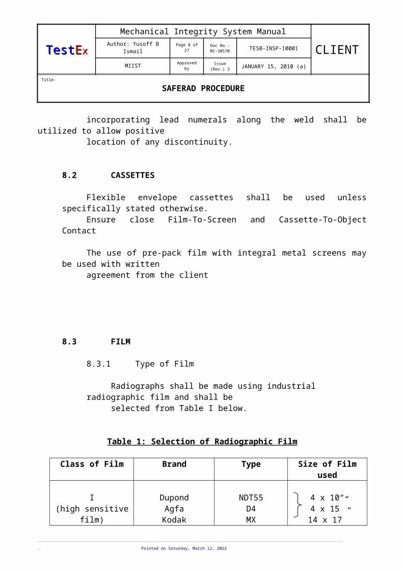
8.3 FILM
8.3.1 Type of Film
Radiographs shall be made using industrial radiographic film and shall beselected from Table I below.
Table 1: Selection of Radiographic Film
Class of Film Brand Type Size of Film used
I(high sensitive film)
DupondAgfa
Kodak
NDT55D4MX
4 x 10“4 x 15”14 x 17”
II(sensitive film)
DupondAgfa
Kodak
NDT70D7CX
4 x 10“4 x 15”14 x 17”
Films shall have sufficient length and shall be placed to produced at least 13 mm of film expose to direct radiation beyond each edge where the weld is terminated
8.3.2 Overlap
If more than one film is required in single exposure, overlapping cassettes shall be used. Radiographs shall have 25 mm overlap at each end to ensure that no portion of the joint remains unexamined. There shall be a specific lead marker visible on both radiographs in the overlap.
8.4 SCREENS
Lead intensifying screens shall be used. The front screen thickness shall normally be 0.125 mm and rear will normally be 0.125 mm.
Screen shall be examined and cleaned on a regular basis (every time before film loading) for dirt or blemishes that may transfer onto the film thus confusion with and masking of defect images.
. Printed on Tuesday, April 18, 2023
TestTestEExx
Mechanical Integrity System Manual
CLIENTAuthor: Yusoff B Ismail Page 7 of 19 Doc No.:MI-30570 TESB-INSP-10001
MIIST Approved by Issue (Rev.) 3 JANUARY 15, 2010 (a)
Title:
SAFERAD PROCEDURE
8.5 GAMMA RAY SOURCE The Selenium-75, an artificial isotope with a half-life of 119.8 days shall be used.
8.5.1 Source SizeThe size of Se-75 source shall be as per stated in the supplier’s decay curves i.e diameter 3.0 mm, length 3.0 mm and diagonal 4.24 mm
8.5.2 Source StrengthFor safety reasons the maximum source strength in every container is limit to 80 curies (3 Tbq)
9.0 RADIOGRAPHIC PROCEDURE.
9.1 Radiographic Inspection techniques Radiographic Inspection techniques shall be carried out in accordance with the current edition of ASME section V Article 2.
A single-wall exposure technique shall be used for radiography whenever practical. When it is not practical to use a single-wall technique, a double-wall technique shall be used. An adequate number of exposures shall be made to demonstrate that the required coverage has been obtained.
9.1.1 Single-Wall TechniqueIn the single-wall technique, the radiation passes through on one wall of the weld (material), which is viewed for acceptance on the radiograph.
9.1.2 Double-Wall Technique.When it is not practical to use a single-wall technique, one of the following double-wall techniques shall be used.
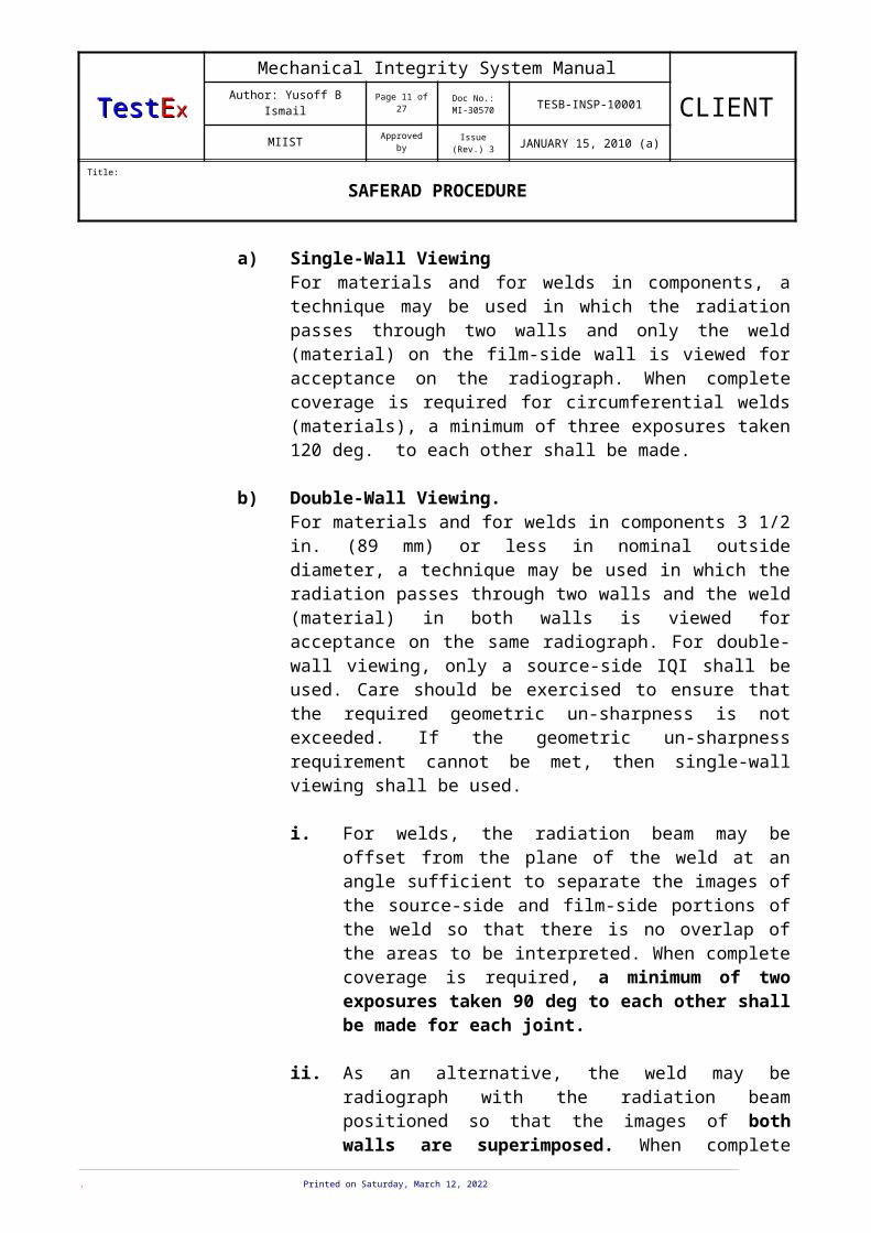
a) Single-Wall ViewingFor materials and for welds in components, a technique may be used in which the radiation passes through two walls and only the weld (material) on the film-side wall is viewed for acceptance on the radiograph. When complete coverage is required for circumferential welds (materials), a minimum of three exposures taken 120 deg. to each other shall be made.
b) Double-Wall Viewing.For materials and for welds in components 3 1/2 in. (89 mm) or less in nominal outside diameter, a technique may be used in which the radiation passes through two walls and the weld (material) in both walls is viewed for acceptance on the same radiograph. For double-wall viewing, only a source-side IQI shall be used. Care should be
. Printed on Tuesday, April 18, 2023
TestTestEExx
Mechanical Integrity System Manual
CLIENTAuthor: Yusoff B Ismail Page 8 of 19 Doc No.:MI-30570 TESB-INSP-10001
MIIST Approved by Issue (Rev.) 3 JANUARY 15, 2010 (a)
Title:
SAFERAD PROCEDURE
exercised to ensure that the required geometric un-sharpness is not exceeded. If the geometric un-sharpness requirement cannot be met, then single-wall viewing shall be used.
i. For welds, the radiation beam may be offset from the plane of the weld at an angle sufficient to separate the images of the source-side and film-side portions of the weld so that there is no overlap of the areas to be interpreted. When complete coverage is required, a minimum of two exposures taken 90 deg to each other shall be made for each joint.
ii. As an alternative, the weld may be radiograph with the radiation beam positioned so that the images of both walls are superimposed. When complete coverage is required, a minimum of three exposures taken at either 60 deg or 120 deg to each other shall be made for each joint.
iii. Additional exposures shall be made if the required radiographic coverage cannot be obtained using the minimum number of exposures indicated in (i) or (ii) above.
9.3 GEOMETRIC RELATIONSHIPS
9.3.1 The geometric un-sharpness of the radiograph shall be determined in accordance in accordance with:-
Geometric un-sharpness, Ug = Fd/(S-d)
Where Ug - geometric un-sharpnessF - focal spot size of source sized - object to film distanceS - focal spot-to-film distance (x-ray) or source-to-film distance
(Gamma Ray)
9.3.2 Geometric Un-sharpness of the radiograph shall not exceed the Ug value in table 2 below and the value of geometric un-sharpness shall be recorded in the report.
Table 2: Maximum Geometric Un-sharpness
Material Thickness, mm Ug Maximum, mmUnder 50.8
50.8 through 76.2Over 76.2 through 101.6
Greater than 101.6
0.510.761.021.78
. Printed on Tuesday, April 18, 2023

TestTestEExx
Mechanical Integrity System Manual
CLIENTAuthor: Yusoff B Ismail Page 9 of 19 Doc No.:MI-30570 TESB-INSP-10001
MIIST Approved by Issue (Rev.) 3 JANUARY 15, 2010 (a)
Title:
SAFERAD PROCEDURE
Material thickness is the thickness on which the IQI is based. This shall be the base metal or parent metal plus the maximum allowable reinforcement. For welds at transition thickness, material thickness shall be the thinner base metal.
9.4 IMAGE QUALITY INDICATORS (IQI)
9.4.1 Selection of IQI
The IQI provides a guide to the quality of radiographs produced and shallbe appropriately chosen from one of the types recommended in ASME Section V Article 2 (As per Table 3 & 3a below).
Table 3: Wire IQI Designation, Wire Diameter And Wire Identity
Set A Set B Set C Set D
WireDiameter,
inMm
WireIdentity
WireDiameter,
inmm
WireIdentity
WireDiameter,
inmm
WireIdentity
WireDiameter,
inmm
WireIdentity
0.00320.0040.0050.00630.0080.010
0.080.010.130.160.200.25
123456
0.0100.0130.0160.0200.0250.032
0.250.330.410.510.640.81
67891011
0.0320.0400.0500.0630.0800.100
0.811.021.271.602.032.54
111213141516
0.1000.1260.1600.2000.2500.320
2.543.204.065.086.358.13
161718192021
Table 3a: IQI Selection________________________________________________________________________________
_ IQI
Source Side Film Side
Material Thickness Range Hole-Type Wire-Type Hole-Type Wire-TypeIn. mm Designation Essential Designation Essential Wire
Up to 0.25, incl. Up to 6.4, incl. 12 5 10 4 Over 0.25 through 0.375 Over 6.4 through 9.5 15 6 12 5Over 0.375 through 0.50 Over 9.5 through 12.7 17 7 15 6Over 0.50 through 0.75 Over 12.7 through 19.0 20 8 17 7Over 0.75 through 1.00 Over 19.0 through 25.4 25 9 20 8Over 1.00 through 1.50 Over 25.4 through 38.1 30 10 25 9Over 1.50 through 2.00 Over 38.1 through 50.8 35 11 30 10Over 2.00 through 2.50 Over 50.8 through 63.5 40 12 35 11Over 2.50 through 4.00 Over 63.5 through 101.6 50 13 40 12Over 4.00 through 6.00 Over 101.6 through 152.4 60 14 50 13Over 6.00 through 8.00 Over 152.4 through 203.2 80 16 60 14Over 8.00 through 10.00 Over 203.2 through 254.0 100 17 80 16Over 10.00 through 12.00 Over 254.0 through 304.0 120 18 100 17Over 12.00 through 16.00 Over 304.0 through 406.4 160 20 120 18Over 16.00 through 20.00 Over 406.4 through 508.0 200 21 160 20_________________________________________________________________________________________________________________________
. Printed on Tuesday, April 18, 2023

TestTestEExx
Mechanical Integrity System Manual
CLIENTAuthor: Yusoff B Ismail Page 10 of 19 Doc No.:MI-30570 TESB-INSP-10001
MIIST Approved by Issue (Rev.) 3 JANUARY 15, 2010 (a)
Title:
SAFERAD PROCEDURE
a) Source Side IQI(s)The IQI(s) shall be placed on the source side of the part being examined, except in the condition described in 12.2 b.
b) Film Side IQI(s)Where inaccessibility prevents hand placing the IQI(s) on the source side it shall be placed on the film side in contact with the part being examined. A lead letter 'F at least as high as the IQI identification numbers) shall be paced adjacent the IQI(s).
Radiography shall be performed with a technique of sufficient sensitivity to display the IQI image and the designated or smallest wire for required sensitivity, which are essential indications of the image quality of the radiograph. The radiographs shall also display the identifying number and letters.
9.4.2 Number of Image Quality Indicator (IQI)
IQI shall show clearly on each radiograph. For a radiograph represents 255 mm or greater of weld length, two IQIs shall be placed; one at each end of the weld length. For radiograph represents less than 255mm of weld length, one IQI shall be placed at any end of the weld length. IQI shall be perpendicular to the joint with the smallest wire on the outer edge of the area being radiographed.
Figure 1 and Figure 2 illustrate the arrangement of lQI(s) locations.
For tubular structure, the following exception minimum number and requiredlocations of IQI shall be followed:-
a) Where the source is located at the center of the tubular structure and
one or more film holders are used for a single exposure of complete circumference(Panoramic Technique), at least three Image Quality Indicator (IQI) shall be spaced approximately 120 apart
b) Where the source is placed at the center of the component (Single-Wall Single-Image Viewing) and four or more film holders are used for a single exposure of a section of the circumference, at least three Image Quality Indicator (IQI) shall be used. One IQI shall be placed at the center of the section exposed and one each at the end.
c) Where the source is located on the axis of the object (Double-Wall Single Viewing Technique) and four or more film holders are used for an exposure of a circumferential weld, at least three Image Quality Indicator (IQI) shall be used. One IQI shall be in the approximate center of the section exposed and one at each end.
. Printed on Tuesday, April 18, 2023
TestTestEExx
Mechanical Integrity System Manual
CLIENTAuthor: Yusoff B Ismail Page 11 of 19 Doc No.:MI-30570 TESB-INSP-10001
MIIST Approved by Issue (Rev.) 3 JANUARY 15, 2010 (a)
Title:
SAFERAD PROCEDURE
9.5 SENSITIVITY
The required sensitivity for each radiograph shall be based on ASME Standard as in Table 3a Wire Type IQI. Radiography shall be performed with a technique of sufficient sensitivity to display the designated the essential wire of a wire IQI. The radiographs shall also display the IQI identifying numbers and letters
9.6 FILM DENSITY
For each radiograph made, film Density will be measured adjacent to the designated wire of a wire IQI and the area of interest shall be 1.8 minimum for single film viewing for radiographs made with an X-ray source and 2.0 minimum for radiographs made with a gamma ray source. The maximum density shall be 4.0 for either single of composite viewing.
9.7 EXCESSIVE BACKSCATTER
A lead symbol “B” with dimensions of ½ in. (13 mm) in height and 1/16 in. (1.6 mm) in thickness, shall be attached to the back of each film holder during each exposure to determine if backscatter radiation is exposing the film. If a light image of the “B”, appears on a darker background of the radiograph, protection from backscatter is insufficient and the radiograph shall be considered unacceptable. A dark image of the “B” on a background is not cause for rejection.
9.8 FILM PROCESSING
This shall be carried out in accordance with the recognized good practice. Processing shall be carried out using the standard developer and fixer solutions, and shall be in accordance with manufacturers recommendations-
The performance of the processing will be checked daily using control strips of X-ray film exposed to a known density change is marked on a process control chart. Upper and lower limits are marked on the chart to provide controls against which the plot can be monitored. The results are interpreted and corrective action taken if necessary.
The radiographs will be free from imperfections due to processing or any other defects that would interfere with interpretation.
. Printed on Tuesday, April 18, 2023

TestTestEExx
Mechanical Integrity System Manual
CLIENTAuthor: Yusoff B Ismail Page 12 of 19 Doc No.:MI-30570 TESB-INSP-10001
MIIST Approved by Issue (Rev.) 3 JANUARY 15, 2010 (a)
Title:
SAFERAD PROCEDURE
9.8.1 Developing Time/Temperature
Time and temperature are important factors in development. Typically, a temperature of 68 oF (20 oC) is used with a development time of between 5 and 8 minutes. As the temperature of the solution is increased, the speed at which the alkali penetrates is also increased. The details of developing time is as tabulated in Table 4.
Table 4:
Standard Developing TimeDeveloper Temperature
(oC )Developer Temperature
(oF )Developer Time
(minutes)16 61 7.017 63 6.518 64 6.019 66 5.520 68 5.021 70 4.522 72 4.023 73 3.824 75 3.525 77 3.326 79 3.027 81 2.828 82 2.529 84 2.330 86 2.031 88 1.832 90 1.533 91 1.334 93 1.0
9.9 FILM IDENTIFICATION
Each film will be identified by the use of lead symbols to indicate the following minimum information:-a) The job or work-pieceb) The jointc) The section of the jointd) The date of the teste) The welder identification
. Printed on Tuesday, April 18, 2023

TestTestEExx
Mechanical Integrity System Manual
CLIENTAuthor: Yusoff B Ismail Page 13 of 19 Doc No.:MI-30570 TESB-INSP-10001
MIIST Approved by Issue (Rev.) 3 JANUARY 15, 2010 (a)
Title:
SAFERAD PROCEDURE
9.10 VIEWING CONDITION
The radiographs shall be examined in a darkened room. The radiograph viewer shall provide a light source sufficient for the essential IQI wire/hole to be visible for the specific density range. The light from around the outer edges of the radiographs will be masked.
9.11 INTERPRETATION OF RADIOGRAPHS
A calibrated densitometer or calibrated density strip will be kept in close proximity to the viewer and a ‘spot’ high-density illuminator will be available. All comments with regard to film quality and interpretation will recorded on the film folder and on the radiographic report form.
The density of density strips and densitometer calibration shall be verified by comparison with a calibrated step wedge film traceable to a national standard. The densitometer shall be calibrated in accordance with paragraph 5 of ASTM E-1079, calibration of Transmission Densitometers.
Indication from defects shall be assessed in accordance with the requirements of the latest edition Referencing Code section.
10.0 ACCEPTANCE CRITERIA
10.1 For the Pressure Vessel, the Acceptance criteria shall be in accordance to ASME VIII Division 1 Appendix 4. – Rounded indications charts acceptance standard for radiographically determined rounded indications in welds.
10.2 For piping, the acceptance criteria shall be in accordance to ANSI B31.3 Table 341.3.2.
11.0 DOCUMENTATION/RADIOGRAPHIC REPORT
11.1 Written reports shall be prepared giving the results of all performed using the Testex (M) Sdn Bhd Radiographic Form.
11.2 The findings shall be reported in the Report format supported with the sketch shows the defect location and depth (if any). The reports shall be submitted to the Client's Inspector for approval.
. Printed on Tuesday, April 18, 2023

TestTestEExx
Mechanical Integrity System Manual
CLIENTAuthor: Yusoff B Ismail Page 14 of 19 Doc No.:MI-30570 TESB-INSP-10001
MIIST Approved by Issue (Rev.) 3 JANUARY 15, 2010 (a)
Title:
SAFERAD PROCEDURE
12.0 REFERENCES.
ASME Section V Article 2
SNT-TC-1A- Qualification of personnel
Atomic Energy Licensing Act, Malaysia, 1984.
Ionizing Radiation Regulation (licensing) Malaysia, 1986
Ionizing Radiation Regulation (Basic Safety Standard) Malaysia, 1988
Ionizing Radiation Regulation (Transportation) Malaysia, 1989
13.0 ATTACHMENTS
13.1 Appendices
13.2 Inspection and Testing Activity Report Form
13.3 Revision History (If any)
. Printed on Tuesday, April 18, 2023

TestTestEExx
Mechanical Integrity System Manual
CLIENTAuthor: Yusoff B Ismail Page 15 of 19 Doc No.:MI-30570 TESB-INSP-10001
MIIST Approved by Issue (Rev.) 3 JANUARY 15, 2010 (a)
Title:
SAFERAD PROCEDURE
. Printed on Tuesday, April 18, 2023

TestTestEExx
Mechanical Integrity System Manual
CLIENTAuthor: Yusoff B Ismail Page 16 of 19 Doc No.:MI-30570 TESB-INSP-10001
MIIST Approved by Issue (Rev.) 3 JANUARY 15, 2010 (a)
Title:
SAFERAD PROCEDURE
. Printed on Tuesday, April 18, 2023
TestTestEExx
Mechanical Integrity System Manual
CLIENTAuthor: Yusoff B Ismail Page 17 of 19 Doc No.:MI-30570 TESB-INSP-10001
MIIST Approved by Issue (Rev.) 3 JANUARY 15, 2010 (a)
Title:
SAFERAD PROCEDURE
. Printed on Tuesday, April 18, 2023

TestTestEExx
Mechanical Integrity System Manual
CLIENTAuthor: Yusoff B Ismail Page 18 of 19 Doc No.:MI-30570 TESB-INSP-10001
MIIST Approved by Issue (Rev.) 3 JANUARY 15, 2010 (a)
Title:
SAFERAD PROCEDURE
. Printed on Tuesday, April 18, 2023

TestTestEExx
Mechanical Integrity System Manual
CLIENTAuthor: Yusoff B Ismail Page 19 of 19 Doc No.:MI-30570 TESB-INSP-10001
MIIST Approved by Issue (Rev.) 3 JANUARY 15, 2010 (a)
Title:
SAFERAD PROCEDURE
ISSUE AND REVISION STATUS
Revision Status Text Amended Date Authorized
Revision 0 Original Text 15.04.1999 Yusoff Ismail
Revision 1 Add Para 3.0, 5.0 & 15.06.2003 Yusoff Ismail9.0
Revision 2 Para 5.0, 8.0 & 9.0 15.09.2003 Yusoff Ismail
Revision 3 Para 8.0 15.01.2010 Yusoff Ismail
. Printed on Tuesday, April 18, 2023