safe use of robotic arms as input devices
TRANSCRIPT

Safe use of Robotic Arms as Input Devices
A.I. (Adrian Ion) Lazar
MSc Report
Committee: Prof.dr.ir. G.J.M. Krijnen
Dr.ir. D. Dresscher Dr.ir. A.Q.L. Keemink
May 2019
015RAM2019 Robotics and Mechatronics
EE-Math-CS University of Twente
P.O. Box 217 7500 AE Enschede
The Netherlands

ii Safe use of robotic arms as input devices
Adrian Ion Lazar University of Twente
iii
Abstract
The independent research centre i-Botics, founded by TNO and University of Twente, currentlyuses the omega.7 haptic device as a master for the telemanipulation of the KUKA LWR 4+ ro-botic arm as a slave device for tasks that need to be performed in a dangerous or hostile envir-onment for human operators.
To improve this state of the art, the Emika Franka Panda robotic arm is, herein, proposed asreplacement for the omega.7 device. Since human operators are to physically interact withthe Panda robotic arm, strict safety measures prompt for proper energy, force and power lim-itations to be carefully set. The novel master device needs to also fulfil the requirements of ahaptic input device.
Herein, a control methodology was developed and implemented such that the necessary safetyand haptic prerequisites are met. The system successfully passed the four evaluation tests thataddressed its haptic performance and safety. Although the slave device was used as a Gazebosimulation of the KUKA LWR 4+ robotic arm, the design is also valid and recommended for thereal hardware.
Robotics and Mechatronics Adrian Ion Lazar

iv Safe use of robotic arms as input devices
Adrian Ion Lazar University of Twente

v
Contents
1 Introduction 1
1.1 Context . . . . . . . . . . . . . . . . . . . . . . . . . . . . . . . . . . . . . . . . . . . . 1
1.2 Problem statement . . . . . . . . . . . . . . . . . . . . . . . . . . . . . . . . . . . . . 1
1.3 Project goals . . . . . . . . . . . . . . . . . . . . . . . . . . . . . . . . . . . . . . . . . 1
1.4 Report outline . . . . . . . . . . . . . . . . . . . . . . . . . . . . . . . . . . . . . . . . 2
2 Analysis 3
2.1 Safety aspects . . . . . . . . . . . . . . . . . . . . . . . . . . . . . . . . . . . . . . . . 3
2.2 Haptic interface aspects . . . . . . . . . . . . . . . . . . . . . . . . . . . . . . . . . . 10
3 Design and implementation 18
3.1 Current bilateral telemanipulation system . . . . . . . . . . . . . . . . . . . . . . . 18
3.2 Panda haptic device within the bilateral telemanipulation system . . . . . . . . . 19
3.3 Implementation in ROS . . . . . . . . . . . . . . . . . . . . . . . . . . . . . . . . . . 21
4 Evaluation 24
4.1 General setup and methods . . . . . . . . . . . . . . . . . . . . . . . . . . . . . . . . 24
4.2 Test 1 - A transparency test - The haptic performance . . . . . . . . . . . . . . . . . 25
4.3 Test 2 - A safety test - The energy limit . . . . . . . . . . . . . . . . . . . . . . . . . . 30
4.4 Test 3 - A safety test -The power limit . . . . . . . . . . . . . . . . . . . . . . . . . . 33
4.5 Test 4 - A safety test - The force limit . . . . . . . . . . . . . . . . . . . . . . . . . . . 35
4.6 Evaluation conclusion . . . . . . . . . . . . . . . . . . . . . . . . . . . . . . . . . . . 36
5 Conclusion and recommendations 38
5.1 Conclusions . . . . . . . . . . . . . . . . . . . . . . . . . . . . . . . . . . . . . . . . . 38
5.2 Recommendations . . . . . . . . . . . . . . . . . . . . . . . . . . . . . . . . . . . . . 39
A Screw theory applied to human arm kinematics 40
A.1 Building the geometrical Jacobian . . . . . . . . . . . . . . . . . . . . . . . . . . . . 40
A.2 Pseudo-code for obtaining the maximum force . . . . . . . . . . . . . . . . . . . . 41
B Results for test 2 - A safety test - The energy limit 43
Bibliography 44
Robotics and Mechatronics Adrian Ion Lazar
vi Safe use of robotic arms as input devices
Adrian Ion Lazar University of Twente

1
1 Introduction
1.1 Context
i-Botics is an open innovation centre for Research and Development in Interaction Robotics.The independent research centre has been founded by TNO and University of Twente and aimsat developing knowledge and technology for value adding Robotic solutions. One of the topicson which research and development is taken further within i-Botics, is telepresence (remote“being”) and telemanipulation (remote “operation”, “handling”). A typical scenario consists ofa complex task that needs to be performed in a dangerous or hostile environment for a humanoperator to work in. Yet, for the complex task human abilities as judging a situation basedon perception and dexterity are essential. The interface that the operator uses to control therobotic system and receive (haptic) feedback is an important part of a telemanipulation system.Currently, a Force Dimension omega.7 haptic device is used to control a KUKA LWR 4+ roboticarm with an attached RightHand Robotics ReFlex TakkTile robotic hand (see Figure 1.1).
(a) The KUKA LWR 4+ robotic arm with anattached RightHand Robotics ReFlex TakkTilerobotic hand.1
(b) The Omega.7 haptic device. From ForceDimension(2019).
Figure 1.1: Current i-Botics bilateral telemanipulation setup.
1.2 Problem statement
The omega.7 is possibly the world’s most advanced desktop 7-DOF haptic interface to date,making it a good option for controlling a KUKA LWR 4+ robotic arm. Nonetheless, there arestill a few drawbacks: (1) a workspace smaller than that of the KUKA LWR 4+; (2) its inabilityto receive feedback from the KUKA LWR 4+ on the 3 of the 6 degrees of freedom, namely, therotational ones; (3) only one degree of freedom for end-effector grasping control.
1.3 Project goals
The goal of this project is to provide an alternative to the Omega.7 haptic device for the tele-manipulation of the KUKA LWR 4+ robotic arm to be used safely by humans that need to usetelepresence to avoid working in dangerous or hostile locations. The main research questionsof this project are:
1. "How can the Panda robotic arm be safely used in interaction with humans?"
2. "How can the Panda robotic arm be effectively used as a haptic interface device?"
Herein, I bring forward an improvement to the current limitations of the system, by replacingthe omega.7 haptic device with another a robotic arm (i.e. the Emika Franka Panda robotic
1Source: https://www.ram.ewi.utwente.nl/research/project/i-botics.html
Robotics and Mechatronics Adrian Ion Lazar

2 Safe use of robotic arms as input devices
arm). This novel use of a robotic arm as an input haptic device to control the KUKA LWR 4+s,since the robotic arms are usually used as output devices (e.g. pick and place tasks, welding(Erden and Billard, 2014) etc).
The advantages of the Panda robotic arm as input haptic device over the omega.7 are: (1) alarger workspace; (2) its ability to receive feedback from the KUKA LWR 4+ on all 6 degrees offreedom, including, the 3 rotational ones; (3) may have more than one degree of freedom forend-effector grasping control, by attaching an exoskeleton hand, for example.
1.4 Report outline
This thesis report is organized in 5 chapters. The first is a brief introduction to the researchtopic assignment containing the context, problems to be tackled with and the project goal.The second chapter is an analysis performed on the safety and haptic aspects of the proposedalternative for the current state of the art. The design and implementation of the solutions thatresulted from the analysis chapter are then presented in Chapter 3. In Chapter 4, four tests aredetailed as part of the evaluation. Their design and results are presented. Finally, Chapter 5presents the conclusions of this research, followed by recommendations for future work.
Adrian Ion Lazar University of Twente

3
2 Analysis
In this chapter the use of the Panda robotic arm is analysed in terms safety and haptic aspects.For safety, the physical interaction and mechanical interface standards are considered. For theuse of the robotic arm as an input haptic device, the optimal workspace and the continuousforce are discussed in terms of the performance criteria reported by Sun et al. (2017).
2.1 Safety aspects
2.1.1 Safe physical interaction
The interaction between a human and a robotic arm is part of a broader topic known in liter-ature as "Human-Robot Interaction" (HRI). This wide topic includes the collaboration, com-munication, and cooperation between humans and robots. The interaction types can be clas-sified as: (1) physical Human-Robot Interaction (pHRI) and (2) social and cognitive aspects ofHuman-Robot Interactions (cHRI). For the first class of human-robot interactions, safety in-volves preventing harmful collisions between humans and robots operating within a sharedspace. For the safety of the second class of interactions, the focus is on preventing the indirect,psychological harms such as stress, psychological discomfort and robotic violation of socialconventions and norms during interaction (Mumm and Mutlu, 2011; Butler and Agah, 2001).Methods for such pHRI safety are summarized in Lasota et al. (2017), along with methods forthe cHRI safety. However, in this research the focus is on the pHRI and Haddadin and Croft(2016) gives an overview on the state of the art in pHRI.
Safety Standards for HRI
Safety for industrial robots is addressed in a variable of general standards, developed and pub-lished by the International Organization for Standardization (ISO) (Haddadin and Croft, 2016):
• ISO 12100:2010 Safety of Machinery - General Principles for Design - Risk Assessmentand Risk Reductions.
• ISO 13849-1:2008 Safety of Machinery - Safety-Related Parts of Control Systems - Part 1:General Principles for Design (ISO13849, 2008).
• ISO 13855:2010 Safety of Machinery - Positioning of Safeguards With Respect to the Ap-proach Speeds of Parts of the Human Body.
• ISO 10218:2011 Robots and robotic devices - Safety requirements for industrial robots.
• ISO/TS 15066:2016 Robots and robotic devices - Collaborative robots.
The most important industrial robotics standard is the ISO 10218. It was established in the re-cognition of the particular hazards that are presented by industrial robots and industrial robotsystems. It is divided in two parts. The first part titled "Part 1: Robots" (ISO10218-1, 2011) isparticularly dedicated to manufacturers as it covers the robot only. While second part, titled"Part 2: Robot systems and integration" (ISO10218-2, 2011) provides safety requirements forthe integration of industrial robots and industrial robot systems and industrial robot cell(s).
Recent updates to ISO 10218 led to development of new technical specification ISO/TS15066(2016). It provides guidance for collaborative robot operation where a robot and a human sharethe same workspace. This document specifies that 140N is the maximum value allowed for theforce corresponding to the human-robot interaction that takes place at hands level.
Robotics and Mechatronics Adrian Ion Lazar
4 Safe use of robotic arms as input devices
Properties of a robot designed for physical Human-Robot Interaction (pHRI)
In order to talk about safe interactions between robots and human, certain properties are de-sirable from a hardware perspective. The properties of a robot designed for physical Human-Robot Interaction (pHRI) are:
• Lightweight design - enables mobility by optimizing the weight reduction of the entiresystem (including controllers, power supply) (Haddadin and Croft, 2016) and reducesany possible injury that may arise in case of a collision with a human (Tadele, 2014).
• Flexible actuators design - allows reducing the stiffness between an actuator and its load.This results in the following advantages: greater shock tolerance, lower reflected inertiaby decoupling the motor side from the link-side inertia, more stable and accurate forcecontrol in addition to the capacity for storing and releasing energy (Meguenani, 2017).
• Proprioceptive Force/Torque Sensing - allows for contact sensing along the entire robotstructure with measurements of contact magnitude, direction, and knowledge of whichlink was contacted (Haddadin et al., 2008; Haddadin and Croft, 2016).
• Visual motion tracking - achieves real-time collision avoidance (Flacco et al., 2012) bytracking and planning the location of a human partner and predicting its future location.This feature is not desirable for the goal of this research, where the human is in contactwith the robotic arm during operation time. However, it is an important property to con-sider when discussing pHRI in general.
Energy based safety metric constrain
During the physical interaction between a human and a robotic arm two parameters are sourceof danger, for a given shape of the contact surface: the impact peak force created at collisionand the contact force generated after the establishment of a physical contact. The most gen-eric way to include and consider these parameters for guaranteeing safe interaction is to useenergy.The energy is a universal quantity that can describe any physical incidents occurring duringhuman-robot interaction. For example, the impact peak force is directly related to the amountof kinetic energy dissipated at collision and the contact forces mostly derive from the amountof potential energy that accumulates in controller of the robot during physical contact. Inertia,velocity and also the resulting position error during physical contact are all part of the math-ematical expression that describes the dynamics of the controller robot and hence the energy.Safety during human-robot interaction can therefore be ensured by modulating the amountof energy instantaneously deployed by the robot (Meguenani, 2017). Tadele (2014) proposedand tested in a simulation environment a safety layer for a multiple degree of freedom manip-ulator that modulates the energy by injecting damping in the joint space, when an impedancecontroller is used. The total energy in the system is defined as the sum of the kinetic energy ofthe manipulator and the potential energy due to the spatial spring, as part of the impedancecontroller used. The reasons for using energy as a criteria safety follow the work of Wood (1971)and Yoganandan et al. (1996) that identified the maximum allowed energy that can causes headinjuries. Thus, the energy limits defined for the specific types of injuries are:
Elimit =
517J Adult cranium bone failure (2.1)
127J Infant cranium bone failure (2.2)
35J Neck fracture (2.3)
Moreover, Haddadin and Croft (2016) conducted collision experiments with a KUKA/DLR light-weight robot and a systematic injury and pain analysis. They investigated the relationships
Adrian Ion Lazar University of Twente

CHAPTER 2. ANALYSIS 5
between measured impact characteristics and quantities (i.e. impact peak force, impact area,tissue displacement, tissue stiffness, stress, impact velocity, kinetic energy, and energy density)and output parameters, such as pain and injury. The impact area is on the lateral surface ofthe right upper arm of a young adult. During the tests, the reflected mass was kept constantat 3.75kg and the impactor was a sphere with a radius of 12.5mm. The injury was defined us-ing AO-classification (Ruedi et al., 2007) after each impact. All impacts were carried out at thesame location on the human body at increasing impact velocity until the participant stoppedthe experiment as the pain limit was reached. The pain tolerance was recorded on the visualanalogue scale (VAS). The maximum force recorded during the impact experiments that didnot cause a bruise was at an impact peak force of 272.2N, impact velocity of 2.55m/s, resultingin a kinetic energy of 12.2J and pain tolerance in a VAS of 6/10. However, for the context of thisassignment, the border limit is not of interest, and more important are the results that corres-pond to little to no pain. These results score a maximum of 2/10 on the visual analogue scale(VAS) and are summarized in Table 2.1. For more information regarding the experimental testsrefer to page 1843 of Haddadin and Croft (2016).
VAS (x/10) Impact peak force (N) Impact velocity (m/s) Kinetic energy (J)0 9.50 0.20 0.080 59.60 0.88 1.451 81.40 1.11 2.311.5 103.50 1.34 3.372 128.10 1.55 4.50
Table 2.1: The impact data for the lateral surface of the right upper arm. Taken from Table 69.5 Haddadinand Croft (2016).
Herein, the energy limit of 4.5J will be used for implementation because it is a trade-off betweensafety and performance.
Power based safety metric constrain
Another safety metric that can be considered besides the total energy of the system can be onebased on the peak power, such as the Head Impact Power (HIP) proposed by Newman andShewchenko (2000). They investigated and presented the probabilities and the related powervalues of a concussion from the reconstruction of football helmeted head impacts using crashtest dummies. The power limits are then defined as:
Plimit ={
12kW Frontal Impacts (2.4)
10kW Non-Frontal Impacts (2.5)
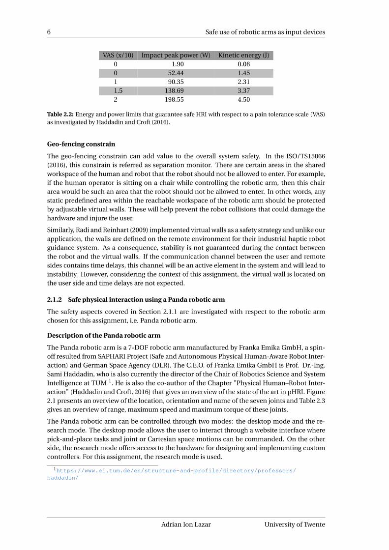
Tadele (2014) uses this power based safety metric in his work where he simulates the perform-ances for limiting the power to 0.5W and 1W. Based on his work, Raiola et al. (2018) implemen-ted and validated it with experiments where the power limit is set to 2W. Using the Table 2.1and the equation 2.6, the impact maximum peak power can be calculated. The safety criterialimits are summarize in Table 2.2. These safety limits will have to allow good haptic perform-ance that is analysed in following section 2.2.
P = F ∗ v (2.6)
Robotics and Mechatronics Adrian Ion Lazar
6 Safe use of robotic arms as input devices
VAS (x/10) Impact peak power (W) Kinetic energy (J)0 1.90 0.080 52.44 1.451 90.35 2.311.5 138.69 3.372 198.55 4.50
Table 2.2: Energy and power limits that guarantee safe HRI with respect to a pain tolerance scale (VAS)as investigated by Haddadin and Croft (2016).
Geo-fencing constrain
The geo-fencing constrain can add value to the overall system safety. In the ISO/TS15066(2016), this constrain is referred as separation monitor. There are certain areas in the sharedworkspace of the human and robot that the robot should not be allowed to enter. For example,if the human operator is sitting on a chair while controlling the robotic arm, then this chairarea would be such an area that the robot should not be allowed to enter. In other words, anystatic predefined area within the reachable workspace of the robotic arm should be protectedby adjustable virtual walls. These will help prevent the robot collisions that could damage thehardware and injure the user.
Similarly, Radi and Reinhart (2009) implemented virtual walls as a safety strategy and unlike ourapplication, the walls are defined on the remote environment for their industrial haptic robotguidance system. As a consequence, stability is not guaranteed during the contact betweenthe robot and the virtual walls. If the communication channel between the user and remotesides contains time delays, this channel will be an active element in the system and will lead toinstability. However, considering the context of this assignment, the virtual wall is located onthe user side and time delays are not expected.
2.1.2 Safe physical interaction using a Panda robotic arm
The safety aspects covered in Section 2.1.1 are investigated with respect to the robotic armchosen for this assignment, i.e. Panda robotic arm.
Description of the Panda robotic arm
The Panda robotic arm is a 7-DOF robotic arm manufactured by Franka Emika GmbH, a spin-off resulted from SAPHARI Project (Safe and Autonomous Physical Human-Aware Robot Inter-action) and German Space Agency (DLR). The C.E.O. of Franka Emika GmbH is Prof. Dr.-Ing.Sami Haddadin, who is also currently the director of the Chair of Robotics Science and SystemIntelligence at TUM 1. He is also the co-author of the Chapter "Physical Human–Robot Inter-action" (Haddadin and Croft, 2016) that gives an overview of the state of the art in pHRI. Figure2.1 presents an overview of the location, orientation and name of the seven joints and Table 2.3gives an overview of range, maximum speed and maximum torque of these joints.
The Panda robotic arm can be controlled through two modes: the desktop mode and the re-search mode. The desktop mode allows the user to interact through a website interface wherepick-and-place tasks and joint or Cartesian space motions can be commanded. On the otherside, the research mode offers access to the hardware for designing and implementing customcontrollers. For this assignment, the research mode is used.
1https://www.ei.tum.de/en/structure-and-profile/directory/professors/haddadin/
Adrian Ion Lazar University of Twente

CHAPTER 2. ANALYSIS 7
Figure 2.1: Overview of joint configuration in the Panda robotic arm (EMIKA, 2018).
Joint name Maximum torque (Nm) Range of motion (°) Maximum velocity (°/s)J0 87 ±166 150J1 87 ±101 150J2 87 ±166 150J3 87 −176/−4 150J4 12 ±166 180J5 12 −1/215 180J6 12 ±166 180
Table 2.3: Panda maximum ratings per joint (EMIKA, 2018).
Safety Standards for HRI
According to the available data-sheet EMIKA (2017) and EMIKA (2018), the robotic arm is "PLd cat. 3 (EN ISO 13849-1:2008)" (ISO13849, 2008) certified, with the following safety functions:
• safe stop - also known as protective stop is a type of interruption of operation that allowsa stoppage of motion for safeguarding purposes and which retains the program logic tofacilitate a restart (definition 3.17 in ANSI/RIA-R15.06 (2012));
• safety-rated monitored stop - condition where the robot is stopped with drive power act-ive, while a monitoring system with a specified sufficient safety performance ensures thatthe robot does not move (definition 3.19.6 in ANSI/RIA-R15.06 (2012));
• safety-rated monitored speed - safety-rated function that causes a protective stop wheneither the Cartesian speed of a point relative to the robot flange (e.g. the gripper end-effector of Panda), or the speed of one or more axes exceeds a specified limit value (defin-ition 3.19.1 in ANSI/RIA-R15.06 (2012));
• safety-rated soft axis and space limiting - where soft limits are software-defined limitsto robot motion and space limiting is used to define any geometric shape which eitherlimits robot motion within the defined space, or prevents the robot from entering thedefined space (definition 3.19.3 in ANSI/RIA-R15.06 (2012));
With regards to the most important standards (i.e. ISO/TS15066 (2016) and ISO10218-2 (2011)),Panda does not officially mention any of them.
Properties of the Panda robotic arm designed for physical Human-Robot Interaction (pHRI)
The Panda robotic arm is advertised as collaborative robot system, designed to work amonghumans. It features three out of the four most important desirable properties a robotic armcan incorporate in its design in order to achieve safe pHRI:
Robotics and Mechatronics Adrian Ion Lazar

8 Safe use of robotic arms as input devices
• Lightweight design - with 18 kg of weight, the Panda robotic arm is considered to belightweight (Haddadin and Croft, 2016).
• Flexible actuators design - based on modular sensor-actuator units (Rader et al., 2017).
• Proprioceptive Force/Torque Sensing - equipped with torque sensors in all 7 axes.
Contact and collision detection as safety metric constrain
The Panda robotic arm does not have any energy and/or power constrains. However, more onthe low level hardware, the manufacturer provides other safety-like feature. Within the softwarelibrary (i.e. libfranka 2), there is a possibility to set torque boundaries for each joint of therobotic arm and a wrench boundary defined in Cartesian space. These boundaries are definedfor contact and collision separately and the difference lies in the way the robotic arm reacts.Contact is triggered only when the user applies a force or torque whose magnitude lies betweenthe lower and upper thresholds, and collision is triggered when that force or torque is higher thehigher threshold. When a collision is registered, the robotic arm stops and a reset is required,by calling the function "franka_control::ErrorRecoveryAction".
The franka_ros metapackage integrates the libfranka into Robot Operating System (ROS) mid-dleware and ROS control software framework. Through this franka_ros interface, two ways ofsetting these torque and wrench boundaries can be chosen from:
• Set common torque and wrench boundaries for acceleration/deceleration and constantvelocity movement phases. Therefore, 4 input parameters are required:
– "lower_torque_thresholds" - the contact torque thresholds for each joint in Nm.
– "upper_torque_thresholds" - the collision torque thresholds for each joint in Nm.
– "lower_force_thresholds" - the contact wrench threshold defined as a six compon-ent vector, where the first three values are X, Y, Z forces in N and the next threevalues are torques around X, Y, Z axis in Nm.
– "upper_force_thresholds" - the collision wrench threshold defined as a six compon-ent vector, where the first three values are X, Y, Z forces in N and the next three valuesare torques around X, Y, Z axis in Nm.
• Set separate torque and wrench boundaries for acceleration/deceleration and constantvelocity movement phases. Therefore, 8 input parameters are required: the same 4 para-meters from above, expressed in 2 cases:
– the robotic arm is in acceleration/deceleration phase (acceleration 6= 0)
– the robotic arm is in constant velocity movement phases (acceleration = 0)
To use this feature, the common torque and wrench boundaries are defined. For the torqueboundaries of each joint, the lower and upper values were set to the maximum torque ofeach joint because explicit values for limiting the joint space of a multiple degree of freedomserial chain manipulator were not found in literature and limiting the wrench in Cartesianspace would limit the torques in joint space as a consequence. Similarly, explicit limits for thetorque component of the wrench boundary were not found in literature and, therefore, a largeenough, meaningless limit was set. However, for the force component of the wrench boundary,ISO/TS15066 (2016) provides the maximum contact force of 140N defined as the maximummagnitude vector force. Therefore, a system is required to compute the magnitude and limitthe force before exceeding the maximum allowed 140N (ISO/TS15066, 2016). Although such asystem will be implemented, for the final system, a conservative measure is taken by using the
2https://frankaemika.github.io/libfranka/index.html
Adrian Ion Lazar University of Twente

CHAPTER 2. ANALYSIS 9
Panda’s library to limit the maximum force on each of the three axis to 80N (p
1402/3), suchthat the combined force vector is always lower than 140N.
Geo-fencing constrain
The geo-fencing feature as discuss in section 2.1.1 consist of preventing the collisions betweenthe robotic arm and an predefined area within the reachable workspace.
The Panda robotic arm already supports the implementation of such feature through their lib-rary "libfranka". In detail, the library offers the possibility of creating data structures called"VirtualWallCuboid" 3. Such a structure is defined by four members. The first member is thevirtual wall ID. The second member is the cuboid’s corner Cartesian location, expressed in thebase frame of the robotic arm. The third member is the transformation matrix, which couldmap the end-effector location and orientation from base frame to virtual wall frame such thatthe virtual wall is defined by the origin of its frame and the diagonal corner (i.e the secondmember of the VirtualWallCuboid). And the fourth, but not least, is a toggle parameter memberthat enables or disables the virtual wall during runtime. In conclusion, the "VirtualWallCuboid"could be used as a method to prevent any collision between the Panda robotic arm and the pre-defined area within its reachable workspace.
2.1.3 Safe mechanical interface
The usage of a robotic arm as an input device requires one or multiple point(s) of contactbetween the robotic arm and the operator. Within the scope of this assignment, a single pointof contact is considered and it is located at the end-effector of the robotic arm and the wrist ofthe operator. This single connection between the robot and human should be made through asafe mechanical interface. This section details one such possible safe interface as reported byHulin et al. (2008).
(a) The view of the connection between the hand ofthe human operator and the end-effector of the ro-botic arm when the two are in contact.
(b) The view of the hand of the human operator andthe end-effector of the robotic arm when the two arenot connected.
Figure 2.2: The magnetic clutch used as a handle by Hulin et al. (2008) in their human machine interface.
The interface is composed of two parts and a locking mechanism. The two components are:
• component 1 - attachable to the end-effector of the robotic arm.
• component 2 - attachable to the human wrist in order to leave the hand free for a futureexoskeleton hand system that will provide the operator with a realistic sensation whenfor example grasping an object.
3https://frankaemika.github.io/libfranka/structfranka_1_1VirtualWallCuboid.html
Robotics and Mechatronics Adrian Ion Lazar

10 Safe use of robotic arms as input devices
The proposed type of the locking mechanism between the two parts is an electromagneticclutch. The two friction surfaces are engaged by the attractive force between a permanentmagnet and an electromagnet. Allowing the clutch to be locked when powered or when un-powered. Since either engaging or disengaging must require activation of the electromagnetresulting in a relatively large amount of energy required, this could result in a problem. As analternative, the electromagnet can be replace with a permanent magnet resulting in no powerconsumption and the loss of the ability to modulate the force required to separate the two fric-tion surfaces (Plooij et al., 2015). In this case, the clutch must be designed so that it releases theuser when the maximum applied forces and torques exceed the maximum force of the clutch.The attaching forces and torques of the clutch is defined by:
• the geometry of the clutch
• the arrangement of the magnets
• the strength of the magnets
Although the interface is an important part of a haptic input device, due to time constrained,the default Panda’s gripper is used so that the focus of this assignment is not on designing andvalidating the interface between a human wrist and an end-effector of a robotic arm. The focusis rather on the safety and haptic usage of the Panda robotic arm in an overall system design.
2.1.4 Conclusion
In conclusion, the safety aspects covered by this sub-chapter aims at answering the first mainresearch question:"How can the Panda robotic arm be safely used in interaction with humans?"
In order to use the Panda robotic arm in interaction with humans, the control algorithm ofPanda should include limitations on the power transferred from the controller to manipulatorand on the total energy of the system, as well as contact force limitation and virtual walls. Thepower and energy limits that will be used in the design and implementation of the Panda’scontroller are summarized in Table 2.2. In case of crushing between a human and a robot, anappropriate index would be the contact force (Haddadin and Croft, 2016). This contact forceshould not exceed 140N according to ISO/TS15066 (2016). The implementation will contain anlimit of 140 N on the translational components of the force generated by the end-effector of thePanda robotic arm. Explicit limits for the rotational components of the force are not reportedin literature to date, to the author’s best knowledge. Therefore, no limit on the rotational forceis applied as such, however, it is partial taken care of through the energy limit.
Another important part of guaranteeing safety during interaction is the human-robot interfacediscussed in section 2.1.3. Due to time limitation the development of such safe interface isleft out of the scope of this thesis. However, the virtual walls will be implemented through thePanda build-in software library such that the reachable workspace of the robotic arm can berestricted to comply with the safety standards.
2.2 Haptic interface aspects
2.2.1 The quality assessment of a haptic device
A haptic device is an actuated human-machine interface which measures the position andforces of the user that operates the device and provides force and torque feedback to the oper-ator through the human sense of touch based on reacting forces and torques from objects in areal, teleoperated, or virtual environment (Srinivasan, 1995).
Haptic devices can either be force-feedback devices or tactile-feedback devices, depending onthe level of feedback provided. Within this research, the Panda robotic arm will be used as a
Adrian Ion Lazar University of Twente

CHAPTER 2. ANALYSIS 11
force feedback device because it addresses the sensations felt by the muscles, joints, and ten-dons. Unlike the tactile-feedback devices that address the sensations felt by the skin, such astexture, temperature, and vibration. The force feedback device is used in a system to increasethe level of immersion the user feels when performing a certain task. This is achieved by dis-playing forces from virtual or real remote environments to the user. End goal is to improve thetask performance of the user.
A good haptic device typically depends on the specific application that is targeted for. Withinthe scope of this assignment, the specific application is not defined. However, a general ap-plication for haptic interactions with either virtual or remote environments is aimed at. Fur-thermore, Sun et al. (2017) highlights the most commonly listed properties of a haptic ground-based force-feedback device, together with their ideal qualitative values. They looked at thecurrently available haptic devices both on the market and in research labs. These properties(Table 2.4) are compared with the Panda robotic arm capabilities in the following section 2.2.2.
Performance criterionQualitativeIdeal
Meaning
Degrees-of-freedom (DOF) High The number of orthogonal motions either permittedor driven by the device.
Workspace High The area or volume in real-world space that the end-effector can reach.
Isotropy High The uniformity of the end-effector moving in allgeneralized workspace directions.
Dexterity/ Manipulability High Quantification of the device’s ease of arbitrarilychanging position and orientation for a given pos-ture.
Inertia Low The resistance felt by the user while moving the end-effector.
Friction Low Forces of resistance that oppose motion.Stiffness High The ability of a device to mimic a solid virtual wall
or object.Input position resolution High The smallest change of position which can be detec-
ted by sensors.Output force resolution High The smallest incremental force that can be gener-
ated by the device.Operating bandwidth High The speed of response to a given excitation.Peak force High The maximum force that the actuators of a device
can generate over a very small time interval.Continuous force High The force that the end-effector can exert for an ex-
tended period.Peak acceleration High The ability of a device to simulate the impact with
stiff virtual objects.
Table 2.4: The most common properties and their ideal qualitative values for haptic devices availableboth on the market and in research labs (Sun et al., 2017).
Robotics and Mechatronics Adrian Ion Lazar

12 Safe use of robotic arms as input devices
2.2.2 The Panda robotic arm
The aim of this section is evaluating the Panda robotic arm based on the most common phys-ical performance requirements of high-performing haptic devices as discussed in section 2.2.1.The Table 2.5 presents the properties from Table 2.4 from the Panda robotic arm point of view.
Performance criterionQualitativeIdeal
Panda robotic arm
Degrees-of-freedom (DOF) High 7 DOF available (Figure 2.1).Workspace High sphere like shape with a radius of 855 mm (Figure
2.3) and section 2.2.3 covers an in-depth analysis.Isotropy High able to uniformly move during certain tasks as long
as suitable initial joint positions are set to avoid therobotic arm reconfiguring its posture due to its jointlimitations.
Dexterity/ Manipulability High Not evaluated.Inertia Low Not evaluated.Friction Low Not evaluated.Stiffness High able to mimic the presence of virtual walls, however
the documentation presents no value for defining itsstiffness.
Input position resolution High the repeatability of the robotic arm task is ±0.1 mm(EMIKA, 2018), which implies that this is also the de-tection limit of a change in position.
Output force resolution High Not evaluated.Operating bandwidth High the control loop runs at 1 kHz.Peak force High Not evaluated.Continuous force High the values for each joint are available (Table 2.3).Peak acceleration High information available only for the commanded end
effector maximum acceleration in translational axisthat is 13 m/s2 and in the rotational axis that is25 rad/s2.4
Table 2.5: The most common properties and their ideal qualitative values for haptic devices (Sun et al.,2017) evaluated for Franka Emika Panda robotic arm.
(a) The arm workspace side view. (b) The arm workspace top view.
Figure 2.3: The workspace of the Panda robotic arm (all numbers are in mm) EMIKA (2018).
4Source: https://frankaemika.github.io/docs/control_parameters.html
Adrian Ion Lazar University of Twente

CHAPTER 2. ANALYSIS 13
2.2.3 The optimal workspace - performance criterion
An important performance criterion is the workspace. The performance of the haptic setupwill not only depend on the workspace of the robotic arm but also on how it is interfaced withthe human right-arm. Ideally, the workspace of the human right-arm should be fully coveredby workspace of the robotic arm. One way would be evaluating various setups using a numberof subjects, and another would be analyzing them using functional criteria. The latter was con-sidered by Zacharias et al. (2010) when analysing the bimanual human-robot interface madeby Hulin et al. (2008). This analysis uses the workspace model (Zacharias et al., 2007), whichquantifies the workspace and includes not only the position that the robotic arm can reach,but also its orientation. Even if a point in space is reachable, certain tasks require also a spe-cific orientation to be properly performed.
(a) Scenario 1 (b) Scenario 2
Figure 2.4: Setups considered for analysis of workspaces (Zacharias et al., 2010).
Zacharias et al. (2010) investigated two scenarios (Figure 2.4) for two cases to compare with:the whole and the restricted human workspace. The restricted human workspace consists ofthe area that humans most use in every day life, following experiments as reported by Howardet al. (2009). In each case, the robotic arm workspace was compared with the human work-space in terms of maximum coverage % and location of the human shoulder. In conclusion,the whole workspace of the human right-arm was covered by the robotic arm by 43% and 63%,in scenario 1 and 2, respectively. Moreover, for the restricted human workspace, the maximumcoverage was 66.8% and 64.4%, in scenario 1 and 2, respectively. Although the scenario 1 scoresa higher maximum coverage in the restricted human workspace, the scenario 2 is recommen-ded to be implemented because the area of the region where the maximum coverage occurs isgreater. Herein, the same ergonomic scenario 2 can be used for the Panda robotic arm setup.We can assume that this scenario is herein suitable, even if the setup investigated by Zachariaset al. (2010) has the DLR-KUKA LWR robotic arm with a sphere-like workspace shape of 936mmradius, because the Panda’s workspace radius of 855mm is larger than the Dutch adult averagearm length of 715mm (Dined, 2004).
Robotics and Mechatronics Adrian Ion Lazar

14 Safe use of robotic arms as input devices
2.2.4 The continuous force - performance criterion
The continuous force is the force that the end-effector can exert for an extended period of time.This value has been discussed from an safety point of view and now haptic performance istaken into account. It makes sense to relate this with the force capabilities of the user. There-fore, the section aims at answering the following secondary research question: "How does theforce safety limit applied to the Panda relates to the maximum force capabilities of a humanarm?"
During the literature review, no complete information was found that relates the maximumforce a human right-arm outputs with the arm configuration within its workspace, in a generalway. However, more commonly used in research is the maximum joint torques a human right-arm outputs (Carignan et al., 2005; Letier et al., 2008). A way to obtain the maximum forcesfrom maximum joint torques is using the screw theory. Screw theory is a tool used in staticand kinematic analysis of rigid bodies and mechanisms. The kinematic modelling of a robotmanipulator describes the relationship between the links and joints that compose its kinematicchain. (Rocha et al., 2011; Stramigioli and Bruyninckx, 2001) To apply the screw theory, a modelof the human arm is needed. Tondu et al. (2005) provides one that was used in designing ananthropomorphic robot-arm. The 7 degrees of freedom (DOF) model can be seen in Figure2.5, in which the arm points towards the ground on the minus x-axis, parallel to the groundtowards right on the minus y-axis and parallel to the ground forward on the minus z-axis. Thesame human right-arm model was also used by Zacharias et al. (2010). Table 2.6 summarizesthe joint limits with the corresponding motion of body links in terms of external–internal ro-tation, flexion–extension, and abduction–adduction (Carignan et al., 2005) and the arm max-imum torques extracted from (Table I in Letier et al. (2008)).
JointName motion
(Figure 2.5)Range motion (°)
(Carignan et al., 2005)Maximum torques (Nm)
(Letier et al., 2008)
1 (SA)Shoulder abduction 134
134Shoulder adduction -48
Shoulder flexion 1882 (SF)
Shoulder extension -61115
Arm external (lateral) rotation 34603 (AR)
Arm internal (medial) rotation -97Elbow flexion 142
4 (EF)Elbow extension 0
72
Forearm pronation 8595 (PS)
Forearm supination -90Wrist abduction 47
6 (WA)Wrist adduction -27
21
Wrist flexion 90207 (WF)
Wrist extension -99
Table 2.6: The human right-arm joint limits, name and range of motion and maximum torques.
It is proven in (Stramigioli and Bruyninckx, 2001) that if the energy is exchanged only via the endeffector (hand) and the joints, then it can be assumed through power continuity the following:
Phand =W 0,nT 0,0n =W 0,n J (q)q = Pjoints =τq (2.7)
where T 0,0n is the twist of body n with respect to body frame 0 expressed in body frame 0, W 0,n
is the wrench acting on body n expressed in body frame 0 and J (q) is the Jacobian matrix.Moreover, equation 2.8 also holds.
τ= J T (q)(W 0,n) (2.8)
Adrian Ion Lazar University of Twente

CHAPTER 2. ANALYSIS 15
SA 1 TRUNK
SF 8
EF 14
WF 90
- AR
3
2
1
4
5
WA6
90 PS 85
7
X
YZ
-48
-61
0
-27
L1
L2
�0
Figure 2.5: The human right-arm model joint frames. Joint limits differ from original Figure by Tonduet al. (2005). Where L1 and L2 are 0.20 m and 0.25 m, respectively.
Equation 2.8 can be used to relate the maximum torques from literature (Table I in Letier et al.(2008)) to the maximum force as part of the wrench (W 0,n = [τx,τy,τz,Fx,Fy,Fz]) through theJacobian matrix computed using screw theory (for details see Appendix A).
Firstly, to simplify the analysis, the Fx, Fy, Fz components of the maximum force exerted by thehuman right-arm on the workspace are considered independently, never more than one at atime, such that, for example, the Fx and Fy would be zero when considering Fz.
Secondly, the human hand joint space, 57 configurations were obtained by discretizing into 5equal parts the motion range of each of the 7 joints (see Table 2.6). Thirdly, for each of the 57
joint configurations, when the torque obtained with a 1N wrench iteration from 0 to 400 N ofequation 2.8 is less or equal than the maximum torque (Table 2.6), the force component of thewrench used for its computation is saved. The iteration runs until either the force or torquereach their threshold, i.e. 400N as reported by Das and Wang (2004) for the force and the val-ues listed in Table 2.6 for the torque. The reported 400N threshold limit was obtain throughuser experiments in which the greatest pull strength was recorded for males and females par-ticipants in the seated and standing positions. The algorithm used to compute the maximumforce capabilities of a human right-arm is available as pseudo-code (Algorithm 1) in AppendixA.2.
Lastly, since there may be more than one joint configuration that allows the human hand toreach a particular location, the workspace was also discretized. By choosing a 5 cm3 area, 441boxes were obtained, such that now a maximum force per box can be calculated. Since eachjoint configuration has its own corresponding force (according to equation 2.8), the workspace
Robotics and Mechatronics Adrian Ion Lazar

16 Safe use of robotic arms as input devices
discretization allows the final number of maximum forces considered to be reduced from 57
to 441. Moreover, these 441 points are on the surface of 5 discrete spheres of radius values0.154 m, 0.272 m, 0.368 m, 0.429 m and 0.450 m. These radius values are obtain from equationA.3 (see Appendix A.1) that considers the human right-arm model shown in Figure 2.5 and alljoint configuration angles.
Results and discussion
To answer the research question that this section addresses, the force exerted by a human right-arm and the literature reported 140N safety limit are compared. Firstly, the individual Fx, Fy
and Fz components of the wrench are determined by iterating equation 2.8. This yields 57
values for each component. Secondly, the number of forces is reduced to 441 by discretizingthe workspace. A histogram can now be used to show the frequency of the 441 values in bins of0 - 140 N, 140 - 280 N and 280 - 420 N, that represent 100%, 200% and 300% of the force limit(Figure 2.6).
a) Forces on x-axis
0 140 280 400Force (N)
0
150
300
441
Fre
quen
cy
b) Forces on y-axis
0 140 280 400Force (N)
0
150
300
441
Fre
quen
cy
c) Forces on z-axis
0 140 280 400Force (N)
0
150
300
441
Fre
quen
cy
42%
24% 28%
67%
5%
33%
100%
Figure 2.6: The histogram of the maximum force components Fx (a), Fy (b) and Fz (c) that the human right-armcan exert in the workspace.
The histogram shows that, the human right-arm acts with the maximum force Fx component(push-pull motion) on 100% of the workspace with a strength higher than 280 N (i.e. 200% ofthe safety force limit), while, on 57% and 33% of the workspace, it acts with a strength lowerthan 280 N with its Fy (left-right motion) and Fz component (up-down motion), respectively(Figure 2.6). In other words, from a safety perspective, the maximum force exerted by the hu-man right-arm exceeds the 140N safety limit, on 100%, 66% and 95% of the workspace for theFx, Fy and Fz components, respectively.
When the 5 discrete spheres of radius values 0.154 m, 0.272 m, 0.368 m, 0.429 m and 0.450 mare considered, the position of the forces that are lower than the safety limit always falls on the0.429m and 0.450m radius spheres for the Fy component, and on the 0.450m radius spherefor the Fz component. Since a clear 3D illustration is not possible, Figure 2.7 shows a 2D-representation of a slice of the total human right-arm workspace on the YZ plane, correspond-ing to the top view of the human right-arm, at shoulder level. The slice thickness is 5 cm, asmuch as the box size used to discretize the workspace. Note that, herein, the human right-armmodel allows forces to be exerted even in the otherwise naturally less accessible area depic-ted with grey in the figure, because the motion range limits of each joint do not consider thelimitations provided by the presence of a human trunk when acting in combination in reality.
Adrian Ion Lazar University of Twente

CHAPTER 2. ANALYSIS 17
-0.5 -0.3 0 0.3 0.5Y-axis
-0.5
-0.3
0
0.3
0.5
Z-ax
is
(a) The Y-axis forces (Fy ).
-0.5 -0.3 0 0.3 0.5Y-axis
-0.5
-0.3
0
0.3
0.5
Z-ax
is
(b) The Z-axis forces (Fz ).
Figure 2.7: A slice of the human right-arm workspace in the YZ plane illustrating the location of the Y-axis(a) andZ-axis(b) maximum forces per 5 cm3 box. The forces that have a magnitude higher or lower than the 140N safetyforce limit are represented by a cross(+) or a circle(o), respectively. The radius of the circles depicted are 0.429m and0.450m for the dotted and straight line, respectively. The grey quarter circle represents the area behind the head,least accessible to a human arm under natural circumstances.
All in all, from a safety perspective, in most reachable workspace of the human right-arm, theuser will be able to overcome the maximum force that the haptic device outputs.
2.2.5 Conclusion
The haptic aspects covered by this sub-chapter aim at answering the second main researchquestion:"How can the Panda robotic arm be effectively used as a haptic interface device?"
Although some performance criteria are not yet evaluated (Table 2.5, according to the avail-able most common properties for haptic devices, the Panda robotic arm has the potential tobe used as a haptic device. Out of all the performance criteria, the workspace and the continu-ous output force were investigated. Based on the work of Zacharias et al. (2010), the optimalPanda robotic arm workspace should be as illustrated in Figure 2.4b (Chapter 2.2.3), becausethe area of the region where the maximum coverage occurs is greater in scenario 2, comparedwith scenario 1, as explained in their article. Regarding the continuous force, the Panda roboticarm will be able to provide one third of the maximum force of the human right-arm within thereachable workspace. This is as good as any devices currently available on the market. Com-mercial devices are in the range of 3N to 20N, and for the research prototypes are in the rangeof 8N to 100N (Sun et al., 2017).
Robotics and Mechatronics Adrian Ion Lazar

18 Safe use of robotic arms as input devices
3 Design and implementation
In this chapter, the design and implementation of the robotic arm as haptic input device to besafely used by humans for telemanipulation is presented. First a state-of-the-art bilateral tele-manipulation system is described. Next, the changes within the system architecture of the tele-manipulation system required to allow the safe use of a Panda robotic arm as a master deviceare presented for both controllers, on the slave and master side. Three safety constrains arediscussed: the energy limit and force limit on the slave side and the power limit on master side.Finally, the implementation of this system in ROS middleware is discussed for the slave andmaster controllers.
3.1 Current bilateral telemanipulation system
For the present project, the state-of-the-art telemanipulation system shown in Figure 3.1 waschosen as a model. It consists of a user being in physical contact with a master device in orderto perform a certain task via the slave device located in a remote environment. The slave deviceneeds to display the behaviour desired by the user performing the task, and the master deviceneeds to accurately provide force feedback based on the interaction between the remote en-vironment and the slave device. The user’s performance of tasks relies on the controllers andcommunication channel, which are the connection between the master and slave devices.
The controllers situated in the channel must guarantee stability of the system and achieve highlevel of transparency, because transparency and stability are two important criteria in bilateraltelemanipulation (Franken et al., 2011; Hashtrudi-Zaad and Salcudean, 2001; Lawrence, 1993).
Figure 3.1: A current telemanipulation system overview.
In general, transparency is a performance measure of how well the complete system is ableto convey to the user the perception of direct interaction with the environment (Lawrence,1993; Hashtrudi-Zaad and Salcudean, 2001). Perfect transparency is technically achieved if theslave position and force are identical to the master position and force (Hashtrudi-Zaad andSalcudean, 2001). Therefore, the transparency layer contains a bilateral control algorithm todisplay the desired behaviour and obtain transparency. In the work of Nijhof (2018), transpar-ency is obtained through an impedance controller located on the slave side. The impedancecontroller calculates the generalized force (the wrench Ws) in the reference frame based on thestiffness of the spatial spring and the relative difference in position and orientation betweenthe end-effector of the master and slave devices.
Stability is the fundamental requirement for every control system (Hashtrudi-Zaad and Sal-cudean, 2001). In particular, for the bilateral telemanipulation systems, unless specially ac-counted for, stable behaviour is compromised in the presence of time-varying destabilizingfactors such as hard contacts, relaxed user grasps, stiff control settings, and/or communicationdelays. In the current system (Nijhof, 2018), stability is achieved through implementation ofpassivity layers that preserves the system stability, even in the presence of time delays in thecommunication channel. The passivity layers ensure that no "virtual" energy is generated. Itshould be located on the slave side and the master side as described by Franken et al. (2011).However, it is not implemented in the final system because of time restrictions. The influence
Adrian Ion Lazar University of Twente

CHAPTER 3. DESIGN AND IMPLEMENTATION 19
of destabilizing factors such as network communication delays and energy generation due todiscretization is expected to be minimal as high enough sampling frequency is assumed.
3.2 Panda haptic device within the bilateral telemanipulation system
The design of this project utilizes for the first time, a Panda robotic arm as a master devicethat complies with the required safety standards (Table 2.2). This requires changes within thesystem architecture to accommodate the three safety constrains: the energy limit and forcelimit on the slave side and the power limit on master side.
3.2.1 The slave side
For this project, the slave controller was designed based on previous work by Nijhof (2018). Themodifications that accommodate the introduction of an energy and force limit to the systemare done in the impedance controller, as can be seen in the signal flow diagram below (Figure3.2). The energy and force limits are summarized in Table 2.2, as part of the analysis chapterconclusion.
Figure 3.2: The slave design architecture. The bold symbols (qs,qs, τ,τD ,Wm,Ws) denote a vector.
The first modification (energy limit) was implemented as described by Tadele (2014) and Raiolaet al. (2018). The total energy of the system is the sum of the kinetic energy of the master device,and the potential energy due to the spatial spring, defined as:
Etot = TK,m(q, q)+Vp(Rsps , psp
s ) (3.1)
where the kinetic energy is calculated, on the master side, as:
TK,m(q, q) = 1
2q>M(q)q (3.2)
where the M(q) is the inertia matrix and q is the joint velocity vector. Furthermore, the potentialenergy Vp stored in the spatial spring is composed of three components Vt, Vo, Vc representingthe translational, rotational, and coupling components, respectively:
Vp(Rsps , psp
s ) =Vt(Rsps , psp
s )+Vo(Rsps )+Vc(Rsp
s , psps ) (3.3)
The potential energy (Vp) is defined in terms of the Rsps and psp
s , which together define theposition and orientation of the relative configuration. The computation of these components(3.3) as defined in the work of Fasse (1997) and Stramigioli (2001) is:
Vt(Rsps , psp
s ) =−1
4tr
(psp
s Gt psps
)− 1
4tr
(psp
s Rsps Gt R s
sp psps
)Vo(Rsp
s ) =−tr(Go Rsp
s)
Vc(Rsps , psp
s ) = tr(Gc R s
sppsps
) (3.4)
Robotics and Mechatronics Adrian Ion Lazar

20 Safe use of robotic arms as input devices
where tr() is the tensor trace operator, and Gt, Go, Gc are the translational, rotational, and coup-ling co-stiffness matrices respectively. The total energy limitation is achieved through regulat-ing the amount of potential energy of the spatial spring. This is possible because the totalenergy of the system is direct proportional with the potential energy (eq. 3.1). As it can beobserved, the potential energy components (3.4) are proportional to the co-stiffness matricesGx (for x= t,o,c). By limiting the co-stiffness matrices, the potential energy is also limited. Theformula for the total initial system energy using the initial co-stiffness matrices Gxi is:
Etoti = TK,m(q, q)+Vpi (Rsps , psp
s ) (3.5)
The actual co-stiffness matrices limiting is done by a factor λ:
Gx =λ ·Gxi for x=t,o,c (3.6)
where depending on the threshold Emax (see Chapter 2.1.1 and the safety limits in Table 2.2), λis calculated as:
λ=
1, Etoti ≤ EmaxEmax −TK,m(q, q)
Vpi (Rsps , psp
s ), otherwise
(3.7)
where Etoti and Vpi are the initial total and potential energies respectively, calculated with theinitial co-stiffness matrices Gxi . Therefore, the total energy of the system expressed as:
Etot = TK,m(q, q)+λ ·Vpi (Rsps , psp
s ) (3.8)
will always be less or equal than the desired threshold value Emax. Moreover, the impedancecontroller now takes into account the total energy in the system that is defined as the sumof the kinetic energy of the master device and the potential energy due to the spatial spring(Stramigioli, 1998).
The second modification (force limit) is implemented on slave side because the generalizedforce (i.e. wrench) of the spatial spring is computed here. In detail, the magnitude of theforce component of the wrench expressed in end-effector frame is limited to the safe force (i.e.140N). It is important that the two wrenches applied to the master and slave devices are equalin magnitude to keep the power continuity concept required for future implementation of thepassivity layers (Franken et al., 2011).
Unlike the impedance controller, the other two components of the transparency layer (the for-ward kinematics and the viscous joint damping) were not modified.
The forward kinematics component contains two functionalities. A functionality translatesjoint positions (qs) to end effector position and orientation represented by a homogeneousmatrix in reference frame with respect to reference frame (Hee,s). And the other functional-ity translates a wrench (Ws), applied to the end effector expressed in reference frame, to jointtorques, applied on individual joints of the KUKA LWR 4+.
The viscous joint damping is part of the control actions for the KUKA LWR 4+. The damping isperformed on joint velocity (qs) available from the robot interface and follows equation 3.9.
τD =−D jqs (3.9)
To sum up, the designed and implemented slave system architecture is presented in Figure 3.2.The network interface and slave robot interface, as well as the transparency layer that medi-ates between them is shown. The signal paths are represented by arrows, both outside and in-side the transparency layer, which contains the component that was modified (the impedancecontroller) as described above, and the two components that were used as such (the forwardkinematics and the joint damping).
Adrian Ion Lazar University of Twente

CHAPTER 3. DESIGN AND IMPLEMENTATION 21
3.2.2 The master side
On the master side, a transparency layer was created between the network interface and themaster robot interface, as described in Figure 3.3. The safe operation of the Panda robotic armis a main objective of the presented work. Therefore, the transparency layer on the master sidewas carefully designed and implemented such that the power variable (Pcm ) is limited and thekinetic energy (TK,m) is transferred over the network to the slave side, where the total energy islimited.
In detail, the power flowing from the controller to the master device is monitored to not exceedthe power limit set according to safety limits (Table 2.2). This power limitation approach hasbeen presented by Raiola et al. (2018) and follows the research of Tadele (2014). If an initialdamping matrix Bi is chosen in joint space, the power from the controller is expressed as:
Pci =(
J>(q)(Wm)>− Biq)>q︸ ︷︷ ︸
Pcm
+ G(q)q︸ ︷︷ ︸Pcg
(3.10)
where J (q) is the manipulator Jacobian that maps joint velocities with generalized velocities(Stramigioli and Bruyninckx, 2001); G(q) is the gravity compensation; q is the joint velocityvector; Wm is the wrench calculated on the slave side; Pcm is the power consumed for providingthe force-feedback to the operator and Pcg is the power consumed for gravity compensation.The Pcm is the power that needs to be limited in case of an uncontrolled collision. This is donethrough adjusting the initial damping with a scaling term β:
B =β · Bi (3.11)
using the threshold values Pmax (Table 2.2), the scaling term β is defined as:
β=
1, Pcm ≤ Pmax(
J>(q)(Wm)>)>q−Pmax
q>Biq, otherwise
(3.12)
Moreover, with respect to the kinetic energy (TK,m(q, q)) of the master device, its value is cal-culated using equation 3.2 before it is being transferred over the network to be included in thelimitation applied to the total energy (equation 3.8).
Figure 3.3: The master design architecture. The bold symbols (qs,qs, τ,Wm) denote a vector.
3.3 Implementation in ROS
The implementation of the designed teleoperation system is done in the Robot Operating Sys-tem (ROS) middleware 1. The three main reasons for using this middleware are: widely usage in
1Source: http://www.ros.org/
Robotics and Mechatronics Adrian Ion Lazar

22 Safe use of robotic arms as input devices
robotic research, official supported interface for the Panda robotic arm and familiarity with theROS concepts. Firstly, the high popularity of ROS in robotics developed a strong communitythat helped it to mature on a software level. Therefore, a stable implementation is possibleif the official guidelines are followed. Secondly, the Panda robotic arm comes with support forROS through "franka_ros" package 2. And thirdly, the familiarity with the middleware is desiredsuch that the implementation is completed within the limited time assigned for this project.
For this project, the master and slave controllers are implemented separately such that com-piling and running the software code can be done on separate computational units.
3.3.1 The slave controller
For the controller implementation of the slave architecture design (Figure 3.2) two choices areworth mentioning: the interface connection of the slave robot and the software writing ap-proach.
First, a KUKA LWR4+ model, simulated in the gazebo physics engine, is chosen to connect tothe slave robot interface such that the system can be tested before involving the real hardware.The chosen model is created by the researchers at Research Center E. Piaggio at the Univer-sity of Pisa, Italy 3. This model can be viewed as a kinematic model, consisting of link lengthsand joint configurations, combined with a dynamic model, consisting of parameters like linkdimensions, inertia and joint friction and damping parameters. Regarding the accuracy of themodel parameters, no detailed investigations are made. The mass properties are assumed real-istic enough based on the mass distribution and the total mass of the links. However, idealizedsettings are used for the static friction and viscous damping parameters at 0.01 (Nm) and 0.01(Nms/rad), respectively. Values follow previous work done by Teeffelen (2018).
Figure 3.4: The KUKA LWR4+ model simulated in Gazebo.
Second, the chosen approach of writing the software follows the guidelines by Ellery (2017) togenerate computational general components. The aim of using the general components ap-
2Source: https://github.com/frankaemika/franka_ros3The model is available on their GitHub: https://github.com/CentroEPiaggio/kuka-lwr
Adrian Ion Lazar University of Twente

CHAPTER 3. DESIGN AND IMPLEMENTATION 23
proach was to structure the software such that each general component is reusable. Towardsthis end, two general components, previously created by Nijhof (2018), are used: forward kin-ematics and impedance controller. First, the forward kinematics component was used withouta change as no change was necessary. Second, the impedance controller component was up-dated to include the total energy limit when computing the generalized force for the masterand slave devices (Wm,Ws), as covered in chapter 3.2.
3.3.2 The master controller
For the controller implementation of the master architecture design (Figure 3.3) three function-alities are included, for testing purposes: (1) the ability to enable and disable the force feedbackreceived from the slave side, (2) the ability to enable and disable the virtual wall (as discussedin chapter 2.1.2) and (3) the ability to set force and torque thresholds for collision behavior (asdiscussed in chapter 2.1.2).
All functionalities are implemented as ROS service calls and are triggered during runtimethrough a command line in a terminal of the bilateral telemanipulation system. The first func-tionality is required because force feedback is generated during the starting of the system dueto slave end-effector not matching the master end-effector position and orientation. There-fore, the system is initialized with the force feedback disabled and after a few seconds, it canbe manually activated. The second functionality follows the reasoning from chapter 2.1.1 andis implemented using the official library "libfranka" that offers the ability to create a "Virtu-alWallCuboid" 4. The properties of the "VirtualWallCuboid" are predefined in the master’scontroller source code since these do not change during runtime. However, the validation ofthe implemented VirtualWallCuboid was not possible because, while Franka Control Interfacedoes provide a way to retrieve the properties of the defined virtual walls, ensuring such the ex-istence of the walls within the software, there is no restriction applied on the end-effector ofthe Panda robotic arm. The third functionality is required to allow the user to interact with thePanda without triggering collision errors as explained in chapter 2.1.2. The default values aretoo low and higher values are set to avoid undesired interruptions.
4Source: https://frankaemika.github.io/libfranka/structfranka_1_1VirtualWallCuboid.html
Robotics and Mechatronics Adrian Ion Lazar

24 Safe use of robotic arms as input devices
4 Evaluation
In this chapter, for the evaluation of the implemented design, a transparency (haptic perform-ance) test and three safety (energy, power and force limit) tests are presented, after a shortsummary of the experimental setup and methods common to all these tests.
4.1 General setup and methods
For testing interactions between the user and objects in a remote environment, a virtual wallis generated in the Gazebo environment, at 2 cm distance from the box supporting the slavedevice, on a plane parallel to the YZ of the chosen reference frame. The master device used isthe actual Panda robotic arm, while the slave device is only a simulation performed in Gazeboof the KUKA LWR 4+ robotic arm, due to time constraints. The PC used is an Intel i7 @ 2.8GHz x8, with 12GB RAM, running a Linux with PREEMPT_RT patched kernel (i.e. 4.14.52-RT34) withUbuntu 16.04 as operating system and the ROS Kinetic as middleware.
Figure 4.1: The Panda robotic arm (top, real hardware) and the KUKA LWR 4+ robotic arm (bottom,simulated model) setup used during the transparency test (haptic performance test) and the three safetytests.
In all the evaluation tests performed, the master and slave device had a similar starting jointconfigurations (see Figure 4.1) that took into consideration the respective range of motion lim-its (KUKA Roboter GmbH, 2012; EMIKA, 2018). With respect to the master device, the bound-aries for the force applied by a user to the robotic arm are set at 80 N and 100 N for contactand collision boundary, respectively. Contact is registered as long as the force and torque arewithin the boundaries and collision is registered whenever they exceed the upper threshold.After collision, a reset is needed before the robotic arm can resume its function. With respectto the slave device, within the transparency layer, the control and frequency parameters areset for the impedance controller as shown in Table 4.1, following previous work (Nijhof, 2018).All stiffness matrices are set to identity matrices multiplied with corresponding spring con-stants. The translational spring constant (kt) of 500 N/m is used, while the orientation springconstant (ko) is 50 Nm/rad. In both cases, too high spring constants would result in unstablebehaviour and too low values would result in high errors between set-point and measured po-
Adrian Ion Lazar University of Twente

CHAPTER 4. EVALUATION 25
sition and orientation of the end-effector. Coupling between commanded motion in rotationand translation domain is not used, therefore the coupling stiffness (kc) is set to zero. The jointdamping (D j) is empirically determined to smooth the output torques given the impedancecontroller settings and the typical commanded motion. The same joint damping value (D j) isused in computing the commanded torques for both the master and slave device. Moreover,the frequency of the communication network middleware ROS ( fROS) matches the impedancecontroller frequency ( fcntrl) at 1kHz.
Parameter Value Unitfcntrl 1 kHzfROS 1 kHzkt 500 N/mko 50 Nm/radkc 0 N/radD j 5 Nms/rad
Table 4.1: The controller parameters.
The evaluation considers four tests, namely, haptic, energy limit, power limit and force limit.For all of these, a set energy, power and force limit is used as shown in Table 4.2. The haptic testuses the same limits discussed in Analysis (section 2.1). However, the safety tests have differentlimits compared to the values established in Analysis, such that there is a different Emax valueset for the energy limit test, a different Pmax value set for the power limit test, and a differentFmax value set for the force limit test.
Energy (J) Power (W) Force (N)Analysis 4.5 198 140Test 1 -haptic performance 4.5 198 140Test 2 - energy limit 3.5 198 140Test 3 - power limit 4.5 5 140Test 4 - force limit 4.5 198 30
Table 4.2: The energy, power and force limits set for each test and discussed in Analysis.
Although all three safety tests have always three limits set (i.e Emax, Pmax, and Fmax), the con-strains are being validated one at a time. The energy, power and force are related also by thestiffness of the spacial virtual spring, joint velocity and the inertia matrix (see Chapter 3). If thelimit is validated, the method can then be applied for any other limit values. A constrain valuechosen for validation must satisfy the following two conditions: (1) be as much as the valueshown in Analysis or lower, and (2) be the first to reach its maximum among all three limits set.Therefore, the values are chosen (see Table 4.2) such that the experiments would not be tiringfor the user, and such that they are the first limit reached.
4.2 Test 1 - A transparency test - The haptic performance
4.2.1 Goal
The two goals of this test are (1) to validate that the end-effector of the slave follows that ofthe master device and (2) to validate that a proper force feedback is established between them.For the first goal, the Cartesian position and orientation of the end-effector of each of the tworobotic arms is evaluated and the error between them is determined. For the second goal ofthis test, the force of the user applied to the virtual wall remotely, and vice-versa, is plotted anddiscussed.
Robotics and Mechatronics Adrian Ion Lazar

26 Safe use of robotic arms as input devices
4.2.2 Method
First and foremost, for initialization (P0) three safety limits are set: 4.5J for the maximum totalenergy that may be allowed between the master and slave devices; 198W for the maximumpower allowed between the master and user; and 140N for the force allowed between the mas-ter and user. Then, while viewing on a screen the slave device simulated in Gazebo environ-ment where there is also a wall, the user moves the master end-effector slowly such that theslave end-effector can be seen approaching the virtual wall on the screen during an approxim-ately 5 second free motion (P1). When the slave end-effector reaches the wall, the user contin-ues to move the master end-effector for approximately 3 more seconds (P2) before moving itback to its initial position and approaching the wall location again (P3). The user repeats theinteraction two more times with the wall for reproducibility (P4 and P6).
For this test, the Cartesian position and orientation of the end-effector of each of the two ro-botic arms is evaluated and the force feedback is validated as follows:
1) For the position, the error vector (et) is computed by subtracting from the master positionvector the slave position vector. The position error ‖et‖ is computed as the norm of the positionvector. The mean and the standard deviation are then calculated for each individual part, aswell as for the two performed motions: free motion (P1,P3 and P5) and wall restricted motion(P2,P4 and P6).
2) For the orientation, the error vector (φ(R)) is defined by the angle difference between themaster (Rm) and slave (Rs) frame of the end-effectors. It is computed using the equation 4.1(equation 29 from (Campa and De La Torre, 2009)). The orientation error ‖eo‖ is computed asthe norm of the orientation angle vector (φ(R)).
φ(R) = 1
2
r32 − r23
r13 − r31
r21 − r12
∈R3, (4.1)
where ri j is the ij-th element of R defined as the error rotation matrix expressing the relativeorientation from the master (Rm) to slave (Rs) with respect to reference frame (equation 28 from(Campa and De La Torre, 2009)):
R = RmRTs (4.2)
Again, the mean and the standard deviation are then calculated for each individual part, as wellas for the two performed motions: free motion (P1,P3 and P5) and wall restricted motion (P2,P4and P6).
3) For the force feedback, the difference between the wrench exerted by the user on the mas-ter device end-effector (Win, input force and torque) and the one exerted by the master deviceend-effector on user (Wm, output force and torque) is computed. The former is provided bythe master device interface that uses the torque sensors of each joint to compute the estim-ated external wrench (force, torque) acting on the end-effector frame, expressed relative to thereference frame; while the latter, is computed by the impedance controller using the spatialspring stiffness parameters and the error in position and orientation of the master and slaveend-effectors. As before, the mean and the standard deviation are then calculated for each in-dividual part, as well as for the two performed motions: free motion (P1, P3 and P5) and wallrestricted motion (P2, P4 and P6).
4.2.3 Expected results
The position and orientation of the end-effector of each of the two robotic arms is expectedto be identical (minimal error) during free motion (P1, P3 and P5) and significantly different(larger error) during wall contact (P2, P4 and P6). Also, a proper force feedback should be es-
Adrian Ion Lazar University of Twente

CHAPTER 4. EVALUATION 27
tablished between the two robotic arms and reflected by an similar plot of the input wrench(Win) and the output wrench (Wm) against time.
4.2.4 Results and discussion
The position and orientation of the end-effector of each of the two robotic arms are closelyoverlapping during free motion (P1, P3 and P5), with errors of 0.026m and 0.075 rad or less,and significantly different during wall contact (P2, P4 and P6), with much larger errors thatreach 0.074m and 0.090 rad (see Figure 4.2). The mean and standard deviation values for eachcase are summarized in Table 4.3. Between the free motion and wall contact parts of the test,the mean for the position is much smaller in the former than the latter, as expected, since theimpedance controller in the latter case is acting as a spring with one fixed extremity. The sameholds true for the mean of the orientation error (see Figure 4.3). The total duration of the freemotion (P1, P3 and P5) adds up to 11.1 seconds, while the interaction with the wall (P2, P4 andP6) is 8.07 seconds.
Figure 4.2: The position in X(a), Y(b) and Z(c) ofthe master (dashed, red) and slave (full, blue) end-effectors during free motion (P1, P3 and P5) andwall restricted motion (P2, P4 and P6).
Figure 4.3: The position(a) and orientation(b) er-ror between the master and slave end-effectorsduring free motion (P1, P3 and P5) and wall re-stricted motion (P2, P4 and P6).
Also, a proper force feedback is indeed established between the two robotic arms. For both theforce (Figure 4.4) and the torque (Figure 4.5) of the action and reaction between the user andmaster device, a good overlap can be seen. During the interaction with the wall (P2, P4 andP6), the force feedback is significantly higher on the X axis compared to the Y and Z axis (Figure4.4). This behaviour is due to the fact that the wall is parallel to the YZ plane of the Cartesianreference frame. While, the torque feedback is almost null on the X axis and reaches its highestand lowest values on the Y and Z axis (Figure 4.5), respectively. This behaviour is again relatedto the wall’s location, which hinders the rotation of the KUKA end-effector around the Y and Zaxis.
During the free motion (P1, P3 and P5), the force and torque are non-zero, as expected, be-cause a complete dynamic compensation was not implemented for both slave and master. Athorough compensation would have to account for inertia, friction, gravity and Coriolis forces.However, herein, only the gravity (G(q), see section 3.2.2) and Coriolis compensations wereconsidered as both were available through the Panda’s build-in software library 1. Therefore,the user feels a resistance from the uncompensated dynamics of the devices involved in theinteraction with the simulated environment.
1Source: https://frankaemika.github.io/libfranka/
Robotics and Mechatronics Adrian Ion Lazar

28 Safe use of robotic arms as input devices
For the whole time (P1-P6), the difference between the input force/torque vector of the userand the output force/torque vector of the Panda (Figure 4.6) is calculated. The minimum, max-imum, mean and standard deviation for each part is summarized in Table 4.4, below. The non-zero difference in forces is proportional to the acceleration of the Panda’s end-effector and itis expected to be non-zero because the experiment involved moving the end-effector at non-constant velocity.
The mean of the force and torque differences during free motion (P1, P3 and P5) is 4.0±2.0Nand 2.7±1.1Nm respectively; and during the wall restricted motion (P2, P4 and P6) it is 3.2±1.5N and 2.6± 1.0N, respectively. The similar values observed between the free motion andwall restricted motion indicates that the system in providing force and torque feedback withconsistency.
Overall, the test results are as expected.
Figure 4.4: The force in X(a), Y(b) and Z(c) of theinput force (full, blue) of the user and the oppositesign output force (dashed, red) of the Panda dur-ing free motion (P1, P3 and P5) and wall restrictedmotion (P2, P4 and P6).
Figure 4.5: The torque in X(a), Y(b) and Z(c) of theinput torque (full, blue) of the user and the oppos-ite sign output torque (dashed, red) of the Pandaduring free motion (P1, P3 and P5) and wall re-stricted motion (P2, P4 and P6).
Position error (‖et‖) (m) Orientation error (‖eo‖) (rad)Min Max Mean Std. Dev. Min Max Mean Std. Dev.
P1 0.001 0.021 0.014 0.004 0.001 0.025 0.017 0.005P3 0.003 0.022 0.013 0.004 0.005 0.075 0.019 0.010P5 0.004 0.026 0.016 0.005 0.006 0.075 0.022 0.011
Free motion(P1,P3,P5)
0.001 0.026 0.014 0.004 0.001 0.075 0.019 0.009
P2 0.005 0.065 0.048 0.018 0.009 0.078 0.044 0.018P4 0.004 0.065 0.055 0.014 0.024 0.084 0.056 0.014P6 0.005 0.074 0.063 0.015 0.023 0.090 0.062 0.015
Wall restrictedmotion
(P2,P4,P6)0.004 0.074 0.055 0.017 0.009 0.090 0.053 0.018
Table 4.3: The minimum, maximum, mean and standard deviation of the position and orientation er-rors between the master and slave end-effectors during free motion (P1, P3 and P5) and wall restrictedmotion (P2, P4 and P6).
Adrian Ion Lazar University of Twente

CHAPTER 4. EVALUATION 29
Figure 4.6: The magnitude force/torque of the difference between the input force/torque vector of theuser and the output force/torque vector of the Panda.
Force (N) Torque (Nm)Min Max Mean Std. Dev. Min Max Mean Std. Dev.
P1 0.549 9.578 4.662 2.419 0.356 5.119 2.433 1.029P3 1.165 8.301 4.333 1.431 0.287 6.713 3.050 1.228P5 1.270 10.168 4.543 1.655 0.498 8.659 3.400 1.439
Free motion(P1,P3,P5)
0.549 10.168 4.073 2.041 0.287 8.659 2.745 1.113
P2 0.609 6.633 3.772 1.830 0.117 5.035 2.318 1.087P4 0.554 5.752 3.029 1.195 1.188 6.716 2.920 0.973P6 0.460 5.337 2.534 0.761 1.318 6.543 2.945 0.930
Wall restrictedmotion
(P2,P4,P6)0.460 6.633 3.206 1.515 0.117 6.716 2.665 1.057
Table 4.4: The minimum, maximum, mean and standard deviation of the difference between the inputforce/torque vector of the user and the output force/torque vector of the Panda, during free motion (P1,P3 and P5) and wall restricted motion (P2, P4 and P6).
Robotics and Mechatronics Adrian Ion Lazar

30 Safe use of robotic arms as input devices
4.3 Test 2 - A safety test - The energy limit
4.3.1 Goal
The goal of this test is to validate the energy limit (Emax) set for a safe human handling of thePanda robotic arm as a haptic input device.
4.3.2 Method
To validate the energy limit, the total energy of the system (eq. 3.1 in Chapter 3) defined asthe sum of the kinetic energy of the master device, and the potential energy due to the spatialspring should either be lower or equal with Emax or else, a factor term (λ) is used to reduce thecomputed wrench (Wp) applied to the user by the Panda robotic arm.
Similar to the first test, for initialization (P0) two safety limits are set: 198W for the maximumpower allowed between the master and user; and 140N for the force allowed between the mas-ter and user. And unlike the first test, for the safety limit herein tested, 3.5J is set as the max-imum total energy that may be allowed between the master and slave devices, in order to re-duce the effort required by the user to reach the limit during the experiment.
While viewing on a screen the slave device simulated in Gazebo environment where there isalso a wall, the user moves the master end-effector slowly such that the slave end-effector canbe seen approaching the virtual wall on the screen during free motion (P1). When the slaveend-effector reaches the wall, the user continues to move the master end-effector (P2) beforemoving it back to its initial position and approaching the wall location again (P3). The userrepeats two more times the interaction with the wall for reproducibility (P4, P5 and P6).
4.3.3 Expected results
At the beginning (P0) of the experiment, both the master and slave end-effectors have identicalstarting configurations and are not in motion. Therefore, the total energy of the system (seeequation 3.1) is expected to be zero due to the potential energy (see equation 3.3) and kineticenergy (see equation 3.2) being zero. During the interaction with the wall (P2, P4 and P6), thetotal energy is expected to exceed the Emax value and, as a result, the wrench feedback shouldbe limited accordingly for the same time periods (P2, P4, P6).
4.3.4 Results and discussion
The total energy of the system is found to be not zero, but −75J (Figure 4.7a), given the control-ler parameters chosen (Kt = 500I ; Ko = 50I ; Kc = 0I ). Therefore, the output force and torqueare not restricted, and user safety is not guaranteed as such. In detail, the total energy value iscalculated to be −75J due to the orientation component of the total energy potential (equation3.4). Assuming identical configurations (i.e. Rsp
s = I ; psps = 0) and eq. 3.4, eq. 4.3 holds.
Vt(Rsps , psp
s ) = 0
Vo(Rsps ) =−tr
(Go Rsp
s)=−75
Vc(Rsps , psp
s ) = 0
(4.3)
where tr() is the tensor trace operator that computes the sum of the diagonal elements; Rsps is
the rotation matrix from the frame orientation of the master end-effector to the one of the slaveend-effector; psp
s is the position vector between the location of the master end-effector to theone of the slave end-effector; and Go is the rotational co-stiffness matrix computed from therotational stiffness matrix (Ko) by eq. 4.4.
Go = 1
2tr(Ko)I −Ko = 25I (4.4)
Therefore, the value is to be considered as an offset determined by the way the rotational po-tential energy is defined in the original formula itself (Tadele, 2014; Raiola et al., 2018). As it is,
Adrian Ion Lazar University of Twente

CHAPTER 4. EVALUATION 31
the implemented energy safety limit can not be validated. The computed total energy is signi-ficantly higher than −75J during the interaction with the virtual wall (P2, P4 and P6) but valuesare always too low to ever trigger the energy safety limit (Emax), which is set to 3.5J. The exactcause of the deviation was not explored in this study due to time restrictions.
Figure 4.7: The system behaviour using the original formula(eq. 3.4) for computing the potential energyof the spatial spring. The total energy system (a); the magnitude force (b) and torque (c) output ofthe master device. The free motion parts are illustrated (P1, P3 and P5) within the figure, while theinteraction with the wall (P2, P4 and P6) are not label within the figure.
A simple way to deal with the offset could be including it in the rotational potential energy(Vo(Rsp
s )) computation by adding a constant value computed from the controller parameterchosen (equation 4.5).
Vo(Rsps ) =−tr
(Go Rsp
s)+ tr(Go) (4.5)
Note that, all signals monitored during the wall interaction P2, P4 and P6 (i.e. the total energy,stiffness factor, force and torque as computed from the impedance controller) have a noisypeak as shown in Appendix B (see figures B.2 and B.1). The noisy instances occur when thestiffness parameters of the impedance controller are constantly updated to reduce the outputforce and torque. To clean the signals a 5-term moving average filter was applied.
The filtered results give a total energy as depicted in Figure 4.8. Both the force and the torqueare limited during the wall interaction once the total maximum energy (Emax) is exceeded (seeTable 4.5). When the computed total energy exceeds the Emax set, the force magnitude does notexceed 58N (Figure 4.9), which is also the mean value approximation over all wall interactionparts (P2, P4, P6) considering the respective standard deviations. Similarly for the torque, whenthe total energy exceeds the Emax set, the torque magnitude does not exceed 55Nm, the meanvalue approximation over all wall interaction parts (P2, P4, P6) is 51Nm. The consistency of allmean values being close to the maximum values and of all standard deviation values being lowproves the efficiency of the energy layer in restricting the output force and torque in situationsthat are unsafe for human users (Etot ≥ Emax).
Robotics and Mechatronics Adrian Ion Lazar

32 Safe use of robotic arms as input devices
Force (N) Torque (Nm)
PartDuration whileEtot ≥ Emax (s)
Max Mean Std. Dev. Max Mean Std. Dev.
P2 1.15 57.86 56.71 1.09 54.21 51.86 1.74P4 2.47 57.35 56.69 0.53 51.42 50.49 0.82P6 3.53 57.88 57.01 0.68 51.22 49.94 1.00
Table 4.5: The maximum, mean and standard deviation of the force and torque while the total energy(Etot) exceeds the total maximum energy (Emax) due to the interaction with the wall (P2, P4 and P6),computed from the filtered data (Figure 4.9).
Herein, the first set of results obtained by following the energy potential definition reportedby Fasse (1997) and Stramigioli (2001), and used by Raiola et al. (2018), do not share the offsetseen in the rotational potential energy computation. It is unclear how Raiola et al. (2018) didnot encounter the same issue and if the tested formula (eq. 4.5) is the proper way to deal withit. Moreover, this requires further investigation which is out of the scope of this project. Non-etheless, the new approach used here, that includes the offset in the rotational potential energy(Vo(Rsp
s )), yielded the expected results.
Figure 4.8: The total energy of the system (a) andthe stiffness factor λ (b), smoothen with a 5-termmoving average filter. The free motion parts areillustrated (P1, P3 and P5) within the figure, whilethe interaction with the wall (P2, P4 and P6) arenot label within the figure.
Figure 4.9: The magnitude of the output force (a)and torque (b) of the master device, smoothenwith a 5-term moving average filter. The free mo-tion parts are illustrated (P1, P3 and P5) within thefigure, while the interaction with the wall (P2, P4and P6) are not label within the figure.
Adrian Ion Lazar University of Twente

CHAPTER 4. EVALUATION 33
4.4 Test 3 - A safety test -The power limit
4.4.1 Goal
The goal of this test is to validate the power limit (Pmax) set for a safe human handling of thePanda robotic arm as a haptic input device.
4.4.2 Method
To validate the power limit, the power consumed for providing force feedback to the user (Pcm )should either be lower or equal than the Pmax or else, a damping scaling term (β) is used totransfer the power difference to the damping matrix (B), which is in turn going to reduce thePcm (see equations: 3.10, 3.11, 3.12 in Chapter 3).
Similar to the first two tests, for initialization two safety limits are set: 4.5J for the maximumtotal energy that may be allowed between the master and slave devices; and 140N for the forceallowed between the master and user. And unlike the first two tests, for the safety limit hereintested, 5W is set as the maximum power (Pmax) allowed between the master and user, in orderto reduce the effort required by the user to reach the limit during the experiment.
While viewing on a screen the slave device simulated in Gazebo environment where there isalso a virtual wall, the user moves the master end-effector and the slave end-effector followsit towards this wall. When the slave end-effector hits the wall, the slave stops following themaster. At this moment the user feels the impact because the master starts pushing back onthe user due to the designed force feedback. The user starts pulling the master away from thewall. After the master end-effector reaches again to its initial position, the user repeats the hitall over again twice for reproducibility. The faster the end-effector moves, the higher the powergenerated from the impact with the virtual wall will be.
4.4.3 Expected results
The interaction that results from the slave end-effector hitting the virtual wall is expected togenerate a higher peak power than the set Pmax. The damping scaling factor (β in eq. 3.12)is recorded during the experiment and it is expected to increase its value. Moreover, the totalscaled power computed with the β factor is expected not to pass the chosen Pmax of 5W.
4.4.4 Results and discussion
Figure 4.10 shows how the total power scaled, the scaling damping factor and the position onthe X axis for the master and slave end-effectors change with time for all three repetitions thatthe user performed. The white areas are times when the user does not move the master andthe slave is away from the virtual wall, while the grey areas are the wall interaction periods. Foreach experiment (i.e. each grey area), the power generated starts at zero and it is first slowlydecreasing as the user is moving the master device. The negative peak power reached corres-ponds to −29.3 W, −25.0 W and −22.0 W for each consecutive experiment. At this moment, theslave device hit the virtual wall and stopped following the master (full versus dashed lines inFigure 4.10c). At this moment the master starts pushing back on the user due to the designedforce feedback and the power is quickly increasing. The moment it reaches zero is the momentin which the master device starts moving such that the slave would be pulled away from thewall, in the opposite direction of the hitting motion. The power generated by the master deviceis from now on positive and from the moment it reaches Pmax, the damping scaling β starts in-creasing (Figure 4.10b) to reduce the Pcm such that it will not exceed the 5W power limit. Whenthe slave resumes following the master, the force feedback is also reduced because there is nolonger a wall interaction. Now the power is again decreasing as the user is again transferringpower to the master. The experiment ends when the master reaches again its initial position.
Robotics and Mechatronics Adrian Ion Lazar

34 Safe use of robotic arms as input devices
Figure 4.10: The total power scaled (a), the scaling damping factor (b), and the position on the X axis forthe master and slave end-effectors (c) change with time. The white areas correspond to the time of noforce feedback, while the grey areas correspond to the three experiment periods. The dotted line in a)denotes the 5W power limit set, i.e. Pmax. The full (blue) and dashed (red) lines in c) correspond to theslave and master end-effectors, respectively.
For this test, the scaled power was monitored by the impedance controller that is used in com-manding the joint torques of the master device. This is less accurate than if the actual power ofthe interaction between the user and the Panda master device would have been independentlymeasured. Nonetheless, the results are as expected, since the power is indeed always less thanPmax, and the test was successful.
Adrian Ion Lazar University of Twente

CHAPTER 4. EVALUATION 35
4.5 Test 4 - A safety test - The force limit
4.5.1 Goal
The goal of this test is to validate the force limit (Fmax) set for a safe human handling of thePanda robotic arm as a haptic input device.
Within the system, two force limits are implemented: (1) one within the control unit of thePanda robotic arm set conservatively as explained in Chapter 2.1.2 to 80N for each of the threeforce axis, and (2) one within the impedance controller located on the slave side. In this section,only the later will be validated because the former is provided and well documented by thePanda’s manufacturer.
4.5.2 Method
To validate the force limit, the force computed as part of the wrench output of the impedancecontroller should be lower in magnitude then the 140N limit (ISO/TS15066, 2016). However, inorder to reduce the effort required by the user to exceed the limit during this experiment, forcelimit of 30N is used. This value is also lower than the 60N reached experimentally when theenergy is at its maximum of 3.5J in the energy limit test. Therefore, it is ensured that the forcelimit is reached before the energy exceeds its maximum set value in this test.
Similar to the previous tests, for initialization (P0) two safety limits are set: 4.5J for the max-imum total energy that may be allowed between the master and slave devices; and 198W forthe maximum power allowed between the master and user.
While viewing on a screen the slave device simulated in Gazebo, the user moves the masterend-effector such that the slave end-effector can be seen approaching the virtual wall. Whenthe slave end-effector is in contact with the wall, the user feels the presence of the wall throughthe force feedback exerted by the master. At this point, the user increases his force on themaster end-effector for a few seconds. The user starts pulling the master away from the wall.After the master end-effector reaches again its initial position, the user repeats the hit all overagain twice for reproducibility.
4.5.3 Expected results
During the interaction with the wall, the magnitude force generated by the impedance control-ler is expected not to exceed the chosen Fmax.
4.5.4 Results and discussion
Figure 4.11 shows the change with time for the magnitude force feedback and the position onthe X axis for the master and slave end-effectors. The white areas correspond to the time ofno force feedback. As the user moves the master end-effector, the force feedback is slowly in-creasing. When the slave end-effector is in contact with the wall, the force feedback has a steepincrease such that the user feels the presence of the wall. However, the magnitude force thatthe master device outputs to the user does not exceed the Fmax of 30N, as expected. When theuser starts pulling the master away from the wall, the force feedback is steeply decreasing untilthe moment in which the slave starts to follow the master again. Until the master end-effectorreaches again its initial position, the force feedback is again slowly increasing and decreasing.The overall shape of the force feedback behaviour with time is, therefore, a sharp peak (wallinteraction) flanked by two smaller peaks (free motion). Although, ideally, all dynamic effects,such as inertia Coriolis and gravity compensation, should be compensated for, this was notdone and leads to the observation of the aforementioned small peaks.
Robotics and Mechatronics Adrian Ion Lazar

36 Safe use of robotic arms as input devices
Figure 4.11: The magnitude force feedback (a) that the Panda haptic device exerts on the user and theposition on the X axis for the master and slave end-effectors (b) change with time. The white areascorrespond to the time of no force feedback, while the grey areas correspond to the three experimentperiods. The dotted line in a) denotes the 30N force limit set, i.e. Fmax. The full (blue) and dashed (red)lines in b) correspond to the slave and master end-effectors, respectively.
4.6 Evaluation conclusion
The haptic performance test (section 4.2 above) concluded that the implemented system allowsthe user to move the master device end-effector and receive force feedback from the simulatedenvironment. The slave device end-effector tracks the location and orientation of the masterwith relatively low mean errors in both position and orientation (see Table 4.3). When inter-acting with a wall, as expected the mean errors in position and orientation are higher and it ismainly due to the interaction control (i.e. impedance control) parameters.
With the energy limit test (section 4.3 above), the method was not validated using the defini-tions of the potential energy stored in the spatial spring (eq. 3.4) as found in literature (Tadele,2014). Therefore, a more practical method to obtain the desired output was implemented andtested, however, further research is required to validate if this is the proper way of dealing withthe issue. In terms of force, although the limit set was 140N, the maximum reached was 60Nbecause that corresponds already to the 3.5J set energy limit.
With the force limit test (section 4.5 above), the method was validated using a set limit of 30Ninstead of the force limit of 140N (ISO/TS15066, 2016). The lower limit was chosen such thatthe user is able to perform the test more comfortably, by not having to consume much energyto test a higher force limit.
The power limit test (section 4.5 above) concluded that the power is indeed limited to 5W,as set. However an external system should be used in the future to accurately measure theinteraction power.
Adrian Ion Lazar University of Twente

CHAPTER 4. EVALUATION 37
In conclusion, three of the four tests validated the methods used and an alternative methodwas validated for the unsuccessful validation of the fourth (i.e. the energy limit test).
Robotics and Mechatronics Adrian Ion Lazar

38 Safe use of robotic arms as input devices
5 Conclusion and recommendations
5.1 Conclusions
This project set out to improve the telemanipulation of a KUKA LWR 4+ robotic arm by repla-cing the omega.7 haptic device currently used to control it with another robotic arm (i.e. theEmika Franka Panda robotic arm). Towards this end, two main research questions were ad-dressed:
1. "How can the Panda robotic arm be safely used in interaction with humans?"
2. "How can the Panda robotic arm be effectively used as a haptic interface device?"
For the first research question, a safety precaution for the human-robot interface, a geo-fencingconstraint, energy, power and force limitations were considered in the Analysis chapter (seesection 2.1) as essential parts of the safe telemanipulation system. From these, the first twolimits were not implemented due to time constraints. Herein, the limitations considered areenergy, power and force. These were implemented and evaluated on a system controlling thecomputer simulated model of a KUKA LWR 4+ robotic arm. The set limit values used for valid-ation are presented in Table 4.2 (see section 4.1).
The energy that Panda robotic arm may transfer to the human operator is limited to a value thatrepresents a safety threshold, above which the user might be harmed. The force that Pandarobotic arm may exert on the human operator is limited to a value that corresponds to thehighest force that the user may withstand without pain at hand level, as defined in the industrialrobotics standard (ISO). The power that Panda robotic arm may instantaneously transfer to thehuman operator during an impact is limited to a value that represents a safety threshold, abovewhich irreversible damage might occur to the user.
The tests performed showed that the implemented algorithm can effectively enforce the spe-cified limits only for the power and the force constrains. The energy constrain was not val-idated. The application of the energy limit using the method reported by Fasse (1997) gaveunexpected results; that method did not allow for a zero starting total energy. The definitionsof the potential energy stored in the spatial spring resulted in the unexpected result of −75J forthe starting energy, given the chosen controller parameters. Therefore, the output force andtorque were not adequately restricted, and the user safety could not be guaranteed as such. Itis unclear how Raiola et al. (2018) did not encounter the same issue in their presented experi-ments.
Herein, another approach to obtain the desired output was implemented and tested where the−75J was treated as an offset. This approach mitigated the offset, which was also done impli-citly by Raiola et al. (2018), and allowed the expected zero starting total energy and the effectiveapplication of the energy bounds in the system. However, this approach was not verified for itsmathematically and physically correctness.
For the second research question, the optimal workspace and continuous output force of thePanda robotic arm were discussed in the Analysis chapter (see section 2.2). The Panda roboticarm has the potential to be used as a haptic input device, as long as its position carefully alignsthe robotic with the human arm workspace. Herein, the force is limited to one third of themaximum force of the human arm within the reachable workspace. Moreover, a haptic testwas performed for evaluation, to validate that (1) the end-effector of the slave follows that ofthe master device and (2) a proper force feedback is established between them. The resultsshowed that the implemented system allows indeed the user to move the master device end-effector and receive force feedback from the simulated environment.
Adrian Ion Lazar University of Twente

CHAPTER 5. CONCLUSION AND RECOMMENDATIONS 39
In conclusion, the goals of this project were successfully met. A control methodology was de-veloped and implemented for the i-Botics telemanipulation system such that the Emika FrankaPanda robotic arm could safely be used by humans as input haptic device for the KUKA LWR4+.
5.2 Recommendations
Based on the results of this work several suggestions can be made for continuation.
Firstly, it was noted that a safe human-robot interface is an essential part of such safe tele-manipulation system which was not covered in this research. This should be designed andimplemented to eventually complete the safe telemanipulation system.
Secondly, the geo-fencing feature through the virtual walls will be beneficial in guaranteeingthe safety of the operator as well as preventing the robot collisions that will damage its hard-ware. However the implemented "VirtualWallCuboid" as provided by the software of the EmikaFranka Panda robotic arm could not be validated due to the delay of the corresponding softwareupdate release date. Therefore, the desired behaviour of the Panda robotic arm in combinationwith the virtual walls should be validated in the future, as soon as the new software is released.
Thirdly, the tests were currently performed based on the internal sensors of the Panda roboticarm and did give some level of validation. However, more reliable tests could be performedusing independent external sensors such as force and motion sensors. For example, the powercould be measured using an external force sensor attached to the end-effector of the Panda andan optical system to track the position of the end-effector.
Fourthly, since the energy limit test could not validate the constrain as originally formulatedand an alternative approach resulted in the expected outcome, for future development of theproject, the mathematically and physically correctness of potential energy definitions of thealternative presented herein should be investigated.
Fifthly, regarding the robotic arm, a recommendation is made for the installation setup basedon the analysis of Zacharias et al. (2010) that considered two scenarios for aligning the roboticwith the human arm workspace. For this project, scenario 2 (see Figure 2.4b, Chapter 2.2.3)is recommended. In that case, the right arm of the human interacts with the right arm of therobotic system. By repositioning the human shoulder with respect to the robotic system, thearea of the region where the maximum coverage occurs is found to be greater in scenario 2compared with scenario 1, making the former a viable option for the future development ofthis project.
Finally, the future follow-up projects should move forward to using the real hardware and as aconsequence address the possible factors affecting the system stability such as network com-munication delays. Therefore, implementation of passivity layers as described by Franken et al.(2011) is recommended for the future development of this novel use of a robotic arm as an inputhaptic device to control the KUKA LWR 4+ in remote and hostile environments.
Robotics and Mechatronics Adrian Ion Lazar

40 Safe use of robotic arms as input devices
A Screw theory applied to human arm kinematics
The goal of applying screw theory to human arm kinematics is to relate the joint torques tothe Cartesian forces. Towards this end, the geometrical Jacobian is computed (section A.1) andapplied in the algorithm described in section A.2.
A.1 Building the geometrical Jacobian
The following steps are performed on the arm model (Figure 2.5) as explained in detailed byStramigioli and Bruyninckx (2001):
1. In joint configuration zero, the difference between coordinate frames are:
p01 = p1
2 = p23 =
000
, p34 =
−L100
, p45 =
−L200
, p56 = p6
7 =0
00
(A.1)
where the two links of the human arm model are defined as L1 and L2 equal with 0.2mand 0.25m, respectively.
2. The human arm model consists of only rotational joint, of which unit rotations are as-signed:
ω0,01 =
001
,ω1,12 =
0−10
,ω2,23 =
−100
,ω3,34 =
0−10
,ω4,45 =
−100
,ω5,56 =
0−10
,ω6,67 =
00−1
(A.2)
3. The direction of rotation for each joint is purely along an axis of the attached coordinateframe. All the coordinate frames are in the same orientation as frame 0 (inertial frame)and are not illustrated in Figure 2.5. Therefore H-matrices (also known as homogeneoustransformation matrix) that describes the relative position of a coordinate frame to thelinked coordinate frame are summarize in table A.1.
For example, Rz−pos is the rotation matrix for a rotation around Z axis in positive direc-tion (using right hand rule), if it is negative, the si n terms get their signs inverted.
The H-matrix that expresses the last frame in inertial frame is obtain by multiplying thehomogeneous matrices:
H 0n = H 0
1 H 12 ...H n−1
n (A.3)
4. A general velocity can be written as a twist in vector form:T c,b
a = [ωx ,ωy ,ωz , vx , vy , vz ]T , which denotes the twist of frame a with respect to frame bexpressed in frame c. Where v is the cross product of p and ω: v = p ×ω. For each of thejoints, the unit twists in inertial frame (frame 0) with respect to previous frame, expressedin previous frame is computed as:
T n−1,n−1n =
[ωn−1,n−1
n
pn−1n ×ωn−1,n−1
n
](A.4)
5. Finally, the geometric Jacobian that maps the joint velocities q = [q1, q2, ...qn]T to endeffector velocity with respect to inertial frame expressed in inertial frame is: (see Strami-gioli and Bruyninckx (2001) if interested in the proof)
J (q) = [T 0,0
1 (q1) T 0,12 (q2) ... T 0,n−1
n (qn)]
(A.5)
Adrian Ion Lazar University of Twente
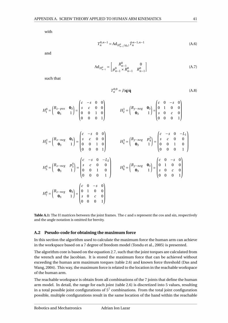
APPENDIX A. SCREW THEORY APPLIED TO HUMAN ARM KINEMATICS 41
with
T 0,n−1n = AdH 0
n−1(qn )Tn−1,n−1n (A.6)
and
AdH 0n−1
=[
R0n−1 0
p0n−1 ×R0
n−1 R0n−1
](A.7)
such that
T 0,0n = J (q)q (A.8)
H 01 =
(Rz−pos 03
03 1
)=
c −s 0 0s c 0 00 0 1 00 0 0 1
H 12 =
(Ry−neg 03
03 1
)=
c 0 −s 00 1 0 0s 0 c 00 0 0 1
H 23 =
(Rx−neg 03
03 1
)=
c −s 0 0s c 0 00 0 1 00 0 0 1
H 34 =
(Ry−neg p3
403 1
)=
c −s 0 −L1
s c 0 00 0 1 00 0 0 1
H 45 =
(Rx−neg p4
503 1
)=
c −s 0 −L2
s c 0 00 0 1 00 0 0 1
H 56 =
(Ry−neg 03
03 1
)=
c 0 −s 00 1 0 0s 0 c 00 0 0 1
H 67 =
(Rz−neg 03
03 1
)=
c 0 −s 00 1 0 0s 0 c 00 0 0 1
Table A.1: The H matrices between the joint frames. The c and s represent the cos and sin, respectivelyand the angle notation is omitted for brevity.
A.2 Pseudo-code for obtaining the maximum force
In this section the algorithm used to calculate the maximum force the human arm can achievein the workspace based on a 7 degree of freedom model (Tondu et al., 2005) is presented.
The algorithm core is based on the equation 2.7, such that the joint torques are calculated fromthe wrench and the Jacobian. It is stored the maximum force that can be achieved withoutexceeding the human arm maximum torques (table 2.6) and known force threshold (Das andWang, 2004). This way, the maximum force is related to the location in the reachable workspaceof the human arm.
The reachable workspace is obtain from all combinations of the 7 joints that define the humanarm model. In detail, the range for each joint (table 2.6) is discretized into 5 values, resultingin a total possible joint configurations of 57 combinations. From the total joint configurationpossible, multiple configurations result in the same location of the hand within the reachable
Robotics and Mechatronics Adrian Ion Lazar

42 Safe use of robotic arms as input devices
workspace. By defining the reachable Cartesian workspace as multiple 5cm3 boxes, one max-imum force can be calculated for each box. Each box is defined by 3 parameters relating tothe X, Y and Z position in the Cartesian space. The considered Cartesian space is ranging from-0.5m to 0.5m with increments of 0.05m for each X, Y and Z axis. The length of the human armmodel is composed of 2 links, measuring 0.2 and 0.25. For each joint configuration of the hu-man arm, the hand location is calculated using homogeneous matrix (eq. A.3) and is stored ina box of the reachable workspace. Using the joint configuration for each box in the reachableworkspace, the maximum force is computed using Algorithm 1.
Algorithm 1: The algorithm used for computing the maximum forces a human arm out-puts within the reachable workspace discretized in boxes of 5cm3.
input : q - 7 joint positions for the 7DOF human armBox - a 5cm3 volume within the reachable workspace of the human armJ (q)> - transpose of the Jacobian in a q joint configurationτmax - maximum torques of the 7DOF human arm
output: M axFor ce - array containing all the maximum forces for each Box.
1 foreach Box do2 foreach q ∈ Box do3 For ce X axi s ← 0;4 while τ< τmax or For ce X axi s ≤ 400 do5 W r ench ← For ce X axi s ; /* Only 1 component of Wrench is
assigned a value, rest are 0. */6 W r ench0 ← Ad>
H 70W r ench ; /* The wrench expresed in hand
frame is expresed to inertial frame. */7 τ← J (q)>W r ench0; /* equation 2.8 */8 For ce X axi s ++;
9 end10 For ces(q) ← For ce X axi s;
11 end12 store M axFor ce(Box) ← maximum For ces of all q within a Box;
13 end
The Algorithm 1 was performed three times for computing the force on all three axis.
Adrian Ion Lazar University of Twente

43
B Results for test 2 - A safety test - The energy limit
With the safety test 2 described in Ch4, the energy limit, the total energy of the system (eq. 3.1in Chapter 3) defined as the sum of the kinetic energy of the master device, and the potentialenergy due to the spatial spring should either be lower or equal with Emax or else, a factor term(λ) is used to reduce the computed wrench (Wp) applied to the user by the Panda robotic arm.The results for both energy and force before filtering out the noise is shown in Figures B.2 andB.1. Note that, all signals measured during the wall interaction P2, P4 and P6 have a noisy peak.The clean signal results obtained with a 5-term moving average filter are shown in the main text(see Figure 4.8 and Figure 4.9).
Figure B.1: The total energy of the system (a) andthe stiffness factorλ (b). The free motion parts areillustrated (P1, P3 and P5) within the figure, whilethe interaction with the wall (P2, P4 and P6) arenot label within the figure.
Figure B.2: The magnitude of the output force (a)and torque (b) of the master device. The free mo-tion parts are illustrated (P1, P3 and P5) within thefigure, while the interaction with the wall (P2, P4and P6) are not label within the figure.
This noisy behavior makes the system momentarily unstable and the reason for it should beconsidered for future troubleshooting. So far, one hypothesis could be that the scaling stiffnessfactor (λ) is faultily computed within the impedance controller general component (see section3.3.1).
Robotics and Mechatronics Adrian Ion Lazar

44 Safe use of robotic arms as input devices
BibliographyANSI/RIA-R15.06 (2012), Industrial Robots And Robot Systems - Safety Requirements, AN-
SI/RIA R15.06-2012, Robotic Industries Association.
Butler, J. T. and A. Agah (2001), Psychological effects of behavior patterns of a mobile personalrobot, vol. 10, no.2, pp. 185–202.
Campa, R. and H. De La Torre (2009), Pose control of robot manipulators using different ori-entation representations: A comparative review, in 2009 American Control Conference, IEEE,pp. 2855–2860.
Carignan, C., M. Liszka and S. Roderick (2005), Design of an arm exoskeleton with scapula mo-tion for shoulder rehabilitation, in ICAR’05. Proceedings., 12th International Conference onAdvanced Robotics, 2005.
Das, B. and Y. Wang (2004), Isometric pull-push strengths in workspace: 1. Strength profiles,vol. 10, no.1, pp. 43–58.
Dined (2004), Anthropometric database, Faculty of Industrial Design Engineering, DelftUniversity of Technology.https://www.dined.nl/
Ellery, D. (2017), Writing reusable code for robotics.
EMIKA, F. (2017), TECHNICAL DATA FRANKA EMIKA - industry, website accessed on:01-05-2017.https://s3-eu-central-1.amazonaws.com/franka-de-uploads-staging/uploads/2017/05/2017-05-12_datasheet-industry.pdf
EMIKA, F. (2018), TECHNICAL DATA Panda, website accessed on: 01-09-2018.https://s3-eu-central-1.amazonaws.com/franka-de-uploads-staging/uploads/2018/05/2018-05-datasheet-panda.pdf
Erden, M. S. and A. Billard (2014), End-point impedance measurements at human handduring interactive manual welding with robot, in 2014 IEEE international conference onrobotics and automation (ICRA), IEEE, pp. 126–133.
Fasse, E. D. (1997), On the spatial compliance of robotic manipulators, vol. 119, no.4, pp.839–844.
Flacco, F., T. Kröger, A. D. Luca and O. Khatib (2012), A depth space approach to human-robotcollision avoidance, in 2012 IEEE International Conference on Robotics and Automation, pp.338–345, ISSN 1050-4729, doi:10.1109/ICRA.2012.6225245.
ForceDimension (2019), Force Dimension Omega.7, website accessed on: 08-03-2019.http://www.forcedimension.com/products/omega-7/overview
Franken, M., S. Stramigioli, S. Misra, C. Secchi and A. Macchelli (2011), Bilateraltelemanipulation with time delays: A two-layer approach combining passivity andtransparency, vol. 27, no.4, pp. 741–756.
Haddadin, S., A. Albu-Schaffer, A. D. Luca and G. Hirzinger (2008), Collision detection andreaction: A contribution to safe physical Human-Robot Interaction, in 2008 IEEE/RSJInternational Conference on Intelligent Robots and Systems, pp. 3356–3363, ISSN 2153-0858,doi:10.1109/IROS.2008.4650764.
Haddadin, S. and E. Croft (2016), Physical Human–Robot Interaction, Springer InternationalPublishing, pp. 1835–1874, ISBN 978-3-319-32552-1, doi:10.1007/978-3-319-32552-1_69.
Adrian Ion Lazar University of Twente

Bibliography 45
Hashtrudi-Zaad, K. and S. E. Salcudean (2001), Analysis of control architectures forteleoperation systems with impedance/admittance master and slave manipulators, vol. 20,no.6, pp. 419–445.
Howard, I. S., J. N. Ingram, K. P. Körding and D. M. Wolpert (2009), Statistics of naturalmovements are reflected in motor errors, vol. 102, no.3, pp. 1902–1910.
Hulin, T., M. Sagardia, J. Artigas, S. Schaetzle, P. Kremer and C. Preusche (2008), Human-scalebimanual haptic interface, Enactive08, pp. 28–33.
ISO10218-1 (2011), Robots and Robotic Devices - Safety Requirements for Industrial Robots -Part 1: Robots, ISO 10218-1:2011, International Organization for Standardization, Geneva.
ISO10218-2 (2011), Robots and Robotic Devices - Safety Requirements for Industrial Robots -Part 2: Robot systems and integration, ISO 10218-2:2011, International Organization forStandardization, Geneva.
ISO13849, E. (2008), 13849-1, Safety of machinery—Safety-related parts of controlsystems—Part, vol. 1, pp. 13849–1.
ISO/TS15066 (2016), Robots and robotic devices – Collaborative robots, ISO/TS 15066:2016,International Organization for Standardization, Geneva.
KUKA Roboter GmbH (2012), Lightweight Robot 4+ specification.
Lasota, P. A., T. Fong, J. A. Shah et al. (2017), A survey of methods for safe human-robotinteraction, vol. 5, no.4, pp. 261–349.
Lawrence, D. A. (1993), Stability and transparency in bilateral teleoperation, vol. 9, no.5, pp.624–637.
Letier, P., M. Avraam, S. Veillerette, M. Horodinca, M. De Bartolomei, A. Schiele andA. Preumont (2008), SAM: A 7-DOF portable arm exoskeleton with local joint control, inIntelligent Robots and Systems, 2008. IROS 2008. IEEE/RSJ International Conference on, IEEE,pp. 3501–3506.
Meguenani, A. (2017), Safe Control of Robotic Manipulators in Dynamic Contexts, Theses,Université Pierre & Marie Curie - Paris 6 ; Institut des Systèmes Intelligents et de Robotique.https://hal.archives-ouvertes.fr/tel-01620663
Mumm, J. and B. Mutlu (2011), Human-robot proxemics: Physical and psychologicaldistancing in human-robot interaction, in 2011 6th ACM/IEEE International Conference onHuman-Robot Interaction (HRI), pp. 331–338, ISSN 2167-2148,doi:10.1145/1957656.1957786.
Newman, J. A. and N. Shewchenko (2000), A proposed new biomechanical head injuryassessment function-the maximum power index, Technical report, SAE Technical Paper.
Nijhof, S. (2018), Teleoperation using passive control and LUNA network channels.
O’Malley, M. and M. Goldfarb (2002), The effect of force saturation on the haptic perception ofdetail, vol. 7, no.3, pp. 280–288.
Plooij, M., G. Mathijssen, P. Cherelle, D. Lefeber and B. Vanderborght (2015), Lock Your Robot:A Review of Locking Devices in Robotics, vol. 22, no.1, pp. 106–117, ISSN 1070-9932,doi:10.1109/MRA.2014.2381368.
Rader, S., L. Kaul, P. Weiner and T. Asfour (2017), Highly integrated sensor-actuator-controllerunits for modular robot design, in 2017 IEEE International Conference on AdvancedIntelligent Mechatronics (AIM), IEEE, pp. 1160–1166.
Radi, M. and G. Reinhart (2009), Industrial Haptic Robot Guidance System for assemblyprocesses, in 2009 IEEE International Workshop on Haptic Audio visual Environments andGames, pp. 69–74, doi:10.1109/HAVE.2009.5356135.
Robotics and Mechatronics Adrian Ion Lazar

46 Safe use of robotic arms as input devices
Raiola, G., C. A. Cardenas, T. S. Tadele, T. de Vries and S. Stramigioli (2018), Development of aSafety-and Energy-Aware Impedance Controller for Collaborative Robots, vol. 3, no.2, pp.1237–1244.
Rocha, C., C. Tonetto and A. Dias (2011), A comparison between the Denavit–Hartenberg andthe screw-based methods used in kinematic modeling of robot manipulators, vol. 27, no.4,pp. 723–728.
Ruedi, T., R. Buckley and C. Moran (2007), AO principles of fracture management, Thieme.
Srinivasan, M. A. (1995), What is haptics?, Laboratory for Human and Machine Haptics: TheTouch Lab, Massachusetts Institute of Technology, pp. 1–11.
Stramigioli, S. (1998), From differentiable manifold to interactive robot control, Ph.D. thesis,TU Delft, Delft University of Technology.
Stramigioli, S. (2001), Modeling and IPC control of interactive mechanical systems—Acoordinate-free approach.
Stramigioli, S. and H. Bruyninckx (2001), Geometry and screw theory for robotics, Tutorialduring ICRA, vol. 2001, p. 75.
Sun, X., K. Andersson and U. Sellgren (2017), Design optimization of haptic device-Asystematic literature review.
Tadele, T. S. (2014), Human-friendly robotic manipulators: safety and performance issues incontroller design, Phd thesis, University of Twente.
Teeffelen, v. K. (2018), Intuitive Impedance Modulation in Haptic Control usingElectromyography.
Tondu, B., S. Ippolito, J. Guiochet and A. Daidie (2005), A seven-degrees-of-freedom robot-armdriven by pneumatic artificial muscles for humanoid robots, vol. 24, no.4, pp. 257–274.
Wood, J. L. (1971), Dynamic response of human cranial bone, vol. 4, no.1, pp. 3–12.
Yoganandan, N., F. Pintar, D. Maiman, J. Cusick, A. Sances Jr and P. Walsh (1996), Humanhead-neck biomechanics under axial tension, vol. 18, no.4, pp. 289–294.
Zacharias, F., C. Borst and G. Hirzinger (2007), Capturing robot workspace structure:representing robot capabilities, in Intelligent Robots and Systems, 2007. IROS 2007. IEEE/RSJInternational Conference on, Ieee, pp. 3229–3236.
Zacharias, F., I. S. Howard, T. Hulin and G. Hirzinger (2010), Workspace comparisons of setupconfigurations for human-robot interaction, in Intelligent Robots and Systems (IROS), 2010IEEE/RSJ International Conference on, IEEE, pp. 3117–3122.
Adrian Ion Lazar University of Twente