sae gateway configuration€¦ · sae gateway configuration configuring gtpp offline accounting on...
TRANSCRIPT

SAE Gateway Configuration
This chapter provides configuration information for the SAE Gateway (SAEGW).
Information about all commands in this chapter can be found in the Command Line Interface Reference.Important
Because each wireless network is unique, the system is designed with a variety of parameters allowing it toperform in various wireless network environments. In this chapter, only the minimum set of parameters areprovided to make the system operational. Optional configuration commands specific to the SAEGWproductare located in the Command Line Interface Reference.
• Configuring an SAEGW Service, page 1
• Configuring an eGTP S-GW Service, page 5
• Configuring Optional Features on the eGTP S-GW, page 14
• Configuring an eGTP P-GW Service, page 32
• Configuring Optional Features on the P-GW, page 59
Configuring an SAEGW ServiceThis section provides a high-level series of steps and the associated configuration file examples for configuringthe system to perform as an SAEGW in a test environment. Information provided in this section includes thefollowing:
• Information Required, on page 1
• SAEGW Configuration, on page 3
Information RequiredThe following sections describe the minimum amount of information required to configure and make theSAEGW operational on the network. To make the process more efficient, it is recommended that thisinformation be available prior to configuring the system.
SAEGW Administration Guide, StarOS Release 21.6 1

There are additional configuration parameters that are not described in this section. These parameters dealmostly with fine-tuning the operation of the SAEGW in the network. Information on these parameters can befound in the appropriate sections of the Command Line Interface Reference.
Required Local Context Configuration InformationThe following table lists the information that is required to configure the local context on an SAEGW.
Table 1: Required Information for Local Context Configuration
DescriptionRequired Information
Management Interface Configuration
An identification string between 1 and 79 characters (alpha and/or numeric)by which the interface will be recognized by the system.
Multiple names are needed if multiple interfaces will be configured.
Interface name
IPv4 addresses assigned to the interface.
Multiple addresses and subnets are needed if multiple interfaces will beconfigured.
IP address and subnet
The physical port to which the interface will be bound. Ports are identifiedby the chassis slot number where the line card resides followed by thenumber of the physical connector on the card. For example, port 17/1identifies connector number 1 on the card in slot 17.
A single physical port can facilitate multiple interfaces.
Physical port number
Used when configuring static IP routes from the management interface(s)to a specific network.
Gateway IP address
The name or names of the security administrator with full rights to thesystem.
Security administrator name
Open or encrypted passwords can be used.Security administrator password
The type of remote access that will be used to access the system such astelnetd, sshd, and/or ftpd.
Remote access type(s)
Required SAEGW Context Configuration InformationThe following table lists the information that is required to configure the SAEGW context on an SAEGW.
SAEGW Administration Guide, StarOS Release 21.62
SAE Gateway ConfigurationInformation Required

Table 2: Required Information for SAEGW Context Configuration
DescriptionRequired Information
An identification string from 1 to 79 characters (alpha and/or numeric) bywhich the SAEGW context will be recognized by the system.
SAEGW context name
SAEGW Service Configuration
An identification string from 1 to 63 characters (alpha and/or numeric) bywhich the SAEGW service will be recognized by the system.
SAEGW service name
An identification string from 1 to 63 characters (alpha and/or numeric) bywhich the S-GW service will be recognized by the system.
S-GW service name
An identification string from 1 to 63 characters (alpha and/or numeric) bywhich the P-GW service will be recognized by the system.
P-GW service name
SAEGW Configuration
Step 1 Set system configuration parameters such as activating PSCs by applying the example configurations found in the SystemAdministration Guide.
Step 2 Set initial configuration parameters such as creating contexts and services by applying the example configurations foundin Initial Configuration, on page 3.
Step 3 Configure the system to perform as an SAEGW and associate an eGTP S-GW service and eGTP P-GW service byapplying the example configurations presented in SAEGW Service Configuration, on page 4.
Step 4 Verify and save the configuration by following the steps found in Verifying and Saving the Configuration, on page 5.
Initial Configuration
Step 1 Set local system management parameters by applying the example configuration in Modifying the Local Context, onpage 4.
Step 2 Create the context where the SAEGW, S-GW, and P-GW services will reside by applying the example configuration inCreating and Configuring an SAEGW Context, on page 4.
Step 3 Configure an eGTP S-GW service by applying the example configurations found in Configuring an eGTP S-GWService,on page 5.
Step 4 Configure an eGTP P-GW service by applying the example configurations found inConfiguring an eGTP P-GWService,on page 32.
SAEGW Administration Guide, StarOS Release 21.6 3
SAE Gateway ConfigurationSAEGW Configuration

Modifying the Local Context
Use the following example to set the default subscriber and configure remote access capability in the localcontext:configure
context localinterface <lcl_cntxt_intrfc_name>
ip address <ip_address> <ip_mask>exit
server ftpdexitserver telnetdexitsubscriber defaultexitadministrator <name> encrypted password <password> ftpip route <ip_addr/ip_mask> <next_hop_addr> <lcl_cntxt_intrfc_name>exitport ethernet <slot/port>
no shutdownbind interface <lcl_cntxt_intrfc_name> localend
Notes:
• Service names must be unique across all contexts within a chassis.
Creating and Configuring an SAEGW Context
Use the following example to create the context where the SAEGW, S-GW, and P-GW services will reside:configure
context <saegw_context_name>end
SAEGW Service Configuration
Configure the SAEGW service by applying the example configuration in Configuring the SAEGW Service, on page4.
Configuring the SAEGW Service
Use the following example to configure the SAEGW service:configure
context <saegw_context_name>
SAEGW Administration Guide, StarOS Release 21.64
SAE Gateway ConfigurationSAEGW Configuration

saegw-service <saegw_service_name> -noconfirmassociate sgw-service <sgw_service_name>associate pgw-service <pgw_service_name>end
Notes:
• The SAEGW, S-GW, and P-GW services must all reside within the same SAEGW context.
• Service names must be unique across all contexts within a chassis.
Verifying and Saving the ConfigurationSave your configuration to flash memory, an external memory device, and/or a network location using theExecmode command save configuration. For additional information on how to verify and save configurationfiles, refer to the System Administration Guide and the Command Line Interface Reference.
Configuring an eGTP S-GW ServiceThis section provides a high-level series of steps and the associated configuration file examples for configuringthe system to perform as an eGTP S-GW in a test environment. Information provided in this section includesthe following:
• Information Required, on page 5
• How This Configuration Works, on page 8
• eGTP S-GW Configuration, on page 10
Information RequiredThe following sections describe the minimum amount of information required to configure and make theS-GW operational on the network. To make the process more efficient, you should have this informationavailable prior to configuring the system.
There are additional configuration parameters that are not described in this section. These parameters dealmostly with fine-tuning the operation of the S-GW in the network. Information on these parameters can befound in the appropriate sections of the Command Line Interface Reference.
Required S-GW Ingress Context Configuration InformationThe following table lists the information that is required to configure the S-GW ingress context on an eGTPS-GW.
SAEGW Administration Guide, StarOS Release 21.6 5
SAE Gateway ConfigurationConfiguring an eGTP S-GW Service

Table 3: Required Information for S-GW Ingress Context Configuration
DescriptionRequired Information
An identification string from 1 to 79 characters (alpha and/or numeric) bywhich the S-GW ingress context is recognized by the system.
The S-GW service must reside within the SAEGW context, thusthis would be the SAEGW context name.
Note
S-GW ingress context name
An identification string from 1 to 63 characters (alpha and/or numeric) bywhich the accounting policy is recognized by the system. The accountingpolicy is used to set parameters for the Rf (off-line charging) interface.
In StarOS releases 19 and later, the Rf interface is notsupported on the S-GW.
Important
Accounting policy name
S1-U/S11 Interface Configuration (To/from eNodeB/MME)
The configuration provided in this guide assumes a shared S1-U/S11 interface. These interfacescan be separated to support a different network architecture. The information below applies to both.
Note
An identification string between 1 and 79 characters (alpha and/or numeric)by which the interface is recognized by the system.
Multiple names are needed if multiple interfaces will be configured.
Interface name
IPv4 or IPv6 addresses assigned to the interface.
Multiple addresses and subnets are needed if multiple interfaces will beconfigured.
IP address and subnet
The physical port to which the interface will be bound. Ports are identifiedby the chassis slot number where the line card resides followed by thenumber of the physical connector on the card. For example, port 17/1identifies connector number 1 on the card in slot 17.
A single physical port can facilitate multiple interfaces.
Physical port number
Used when configuring static IP routes from the interface(s) to a specificnetwork.
Gateway IP address
Used when configuring static IP routes from the interface(s) to a specificnetwork.
Gateway IP address
GTP-U Service Configuration
An identification string from 1 to 63 characters (alpha and/or numeric) bywhich the GTP-U service bound to the S1-U/S11 interface will berecognized by the system.
GTP-U service name (forS1-U/S11 interface)
S1-U/S11 interface IPv4 or IPv6 address.IP address
S-GW Service Configuration
SAEGW Administration Guide, StarOS Release 21.66
SAE Gateway ConfigurationInformation Required

DescriptionRequired Information
An identification string from 1 to 63 characters (alpha and/or numeric) bywhich the S-GW service is recognized by the system.
Multiple names are needed if multiple S-GW services will be used.
S-GW service name
eGTP Ingress Service Configuration
An identification string from 1 to 63 characters (alpha and/or numeric) bywhich the eGTP S1-U/S11 ingress service is recognized by the system.
eGTP S1-U/S11 ingress servicename
Required S-GW Egress Context Configuration InformationThe following table lists the information that is required to configure the S-GW egress context on an eGTPS-GW.
Table 4: Required Information for S-GW Egress Context Configuration
DescriptionRequired Information
An identification string from 1 to 79 characters (alpha and/or numeric) bywhich the S-GW egress context is recognized by the system.
The S-GW service must reside within the SAEGW context, thusthis would be the SAEGW context name.
Note
S-GW egress context name
S5/S8 Interface Configuration (To/from P-GW)
An identification string between 1 and 79 characters (alpha and/or numeric)by which the interface is recognized by the system.
Multiple names are needed if multiple interfaces will be configured.
Interface name
IPv4 or IPv6 addresses assigned to the interface.
Multiple addresses and subnets are needed if multiple interfaces will beconfigured.
IP address and subnet
The physical port to which the interface will be bound. Ports are identifiedby the chassis slot number where the line card resides followed by thenumber of the physical connector on the card. For example, port 17/1identifies connector number 1 on the card in slot 17.
A single physical port can facilitate multiple interfaces.
Physical port number
Used when configuring static IP routes from the interface(s) to a specificnetwork.
Gateway IP address
GTP-U Service Configuration
SAEGW Administration Guide, StarOS Release 21.6 7
SAE Gateway ConfigurationInformation Required

DescriptionRequired Information
An identification string from 1 to 63 characters (alpha and/or numeric) bywhich the GTP-U service bound to the S5/S8 interface will be recognizedby the system.
GTP-U service name (for S5/S8interface)
S5/S8 interface IPv4 or IPv6 address.IP address
eGTP Egress Service Configuration
An identification string from 1 to 63 characters (alpha and/or numeric) bywhich the eGTP egress service is recognized by the system.
eGTP Egress Service Name
How This Configuration WorksThe following figure and supporting text describe how this configuration with a single ingress and egresscontext is used by the system to process a subscriber call.
Figure 1: eGTP S-GW Call Processing Using a Single Ingress and Egress Context
1 A subscriber session from the MME is received by the S-GW service over the S11 interface.
2 The S-GW service determines which context to use to access PDN services for the session. This processis described in the How the System Selects Contexts section located in the Understanding the SystemOperation and Configuration chapter of the System Administration Guide.
SAEGW Administration Guide, StarOS Release 21.68
SAE Gateway ConfigurationHow This Configuration Works
3 S-GW uses the configured egress context to determine the eGTP service to use for the outgoing S5/S8connection.
4 The S-GW establishes the S5/S8 connection by sending a create session request message to the P-GW.
5 The P-GW responds with a Create Session Response message that includes the PGW S5/S8 Address forcontrol plane and bearer information.
6 The S-GW conveys the control plane and bearer information to the MME in a Create Session Responsemessage.
7 The MME responds with a Create Bearer Response and Modify Bearer Request message.
8 The S-GW sends a Modify Bearer Response message to the MME.
SAEGW Administration Guide, StarOS Release 21.6 9
SAE Gateway ConfigurationHow This Configuration Works

eGTP S-GW ConfigurationTo configure the system to perform as an eGTP S-GW, review the following graphic and subsequent steps.
Figure 2: eGTP S-GW Configurable Components
Step 1 Set system configuration parameters such as activating PSCs by applying the example configurations found in the SystemAdministration Guide.
Step 2 Set initial configuration parameters such as creating contexts and services by applying the example configurations foundin Initial Configuration, on page 11.
Step 3 Configure the system to perform as an eGTP S-GW and set basic S-GW parameters such as eGTP interfaces and an IProute by applying the example configurations presented in eGTP Configuration, on page 13.
Step 4 Verify and save the configuration by following the instruction in Verifying and Saving the Configuration, on page 14.
SAEGW Administration Guide, StarOS Release 21.610
SAE Gateway ConfigurationeGTP S-GW Configuration

Initial Configuration
Step 1 Create an ingress context where the S-GW and eGTP ingress service will reside by applying the example configurationin Creating an S-GW Ingress Context, on page 11.
Step 2 Create an eGTP ingress service within the newly created ingress context by applying the example configuration inCreating an eGTP Ingress Service, on page 11.
Step 3 Create an S-GW egress context where the eGTP egress services will reside by applying the example configuration inCreating an S-GW Egress Context, on page 12.
Step 4 Create an eGTP egress service within the newly created egress context by applying the example configuration in Creatingan eGTP Egress Service, on page 12.
Step 5 Create a S-GW service within the newly created ingress context by applying the example configuration in Creating anS-GW Service, on page 12.
Creating an S-GW Ingress Context
Use the following example to create an S-GW ingress context and Ethernet interfaces to anMME and eNodeB,and bind the interfaces to configured Ethernet ports.configure
context <saegw_context_name> -noconfirmsubscriber defaultexitinterface <s1u-s11_interface_name>
ip address <ipv4_address_primary>ip address <ipv4_address_secondary>exit
ip route 0.0.0.0 0.0.0.0 <next_hop_address> <sgw_interface_name>exit
port ethernet <slot_number/port_number>no shutdownbind interface <s1u-s11_interface_name> <saegw_context_name>end
Notes:
• This example presents the S1-U/S11 connections as a shared interface. These interfaces can be separatedto support a different network architecture.
• The S1-U/S11 interface IP address(es) can also be specified as IPv6 addresses using the ipv6 addresscommand.
• Service names must be unique across all contexts within a chassis.
Creating an eGTP Ingress Service
Use the following configuration example to create an eGTP ingress service:configure
context <saegw_context_name>
SAEGW Administration Guide, StarOS Release 21.6 11
SAE Gateway ConfigurationeGTP S-GW Configuration

egtp-service <egtp_ingress_service_name> -noconfirmend
Notes:
• Service names must be unique across all contexts within a chassis.
Creating an S-GW Egress Context
Use the following example to create an S-GW egress context and Ethernet interface to a P-GW and bind theinterface to configured Ethernet ports.configure
context <egress_context_name> -noconfirminterface <s5s8_interface_name> tunnel
ipv6 address <address>tunnel-mode ipv6ip
source interface <name>destination address <ipv4 or ipv6 address>end
configureport ethernet <slot_number/port_number>
no shutdownbind interface <s5s8_interface_name> <egress_context_name>end
Notes:
• The S5/S8 interface IP address can also be specified as an IPv4 address using the ip address command.
• Service names must be unique across all contexts within a chassis.
Creating an eGTP Egress Service
Use the following configuration example to create an eGTP egress service in the S-GW egress context:configure
context <egress_context_name>egtp-service <egtp_egress_service_name> -noconfirmend
Notes:
• Service names must be unique across all contexts within a chassis.
Creating an S-GW Service
Use the following configuration example to create the S-GW service in the ingress context:configure
context <saegw_context_name>sgw-service <sgw_service_name> -noconfirmend
Notes:
• Service names must be unique across all contexts within a chassis.
SAEGW Administration Guide, StarOS Release 21.612
SAE Gateway ConfigurationeGTP S-GW Configuration

eGTP Configuration
Step 1 Set the system's role as an eGTP S-GW and configure eGTP service settings by applying the example configuration inSetting the System's Role as an eGTP S-GW and Configuring GTP-U and eGTP Service Settings, on page 13.
Step 2 Configure the S-GW service by applying the example configuration in Configuring the S-GW Service, on page 14.Step 3 Specify an IP route to the eGTP Serving Gateway by applying the example configuration in Configuring an IP Route,
on page 14.
Setting the System's Role as an eGTP S-GW and Configuring GTP-U and eGTP Service Settings
Use the following configuration example to set the system to perform as an eGTP S-GW and configure theGTP-U and eGTP services:configure
context <saegw_context_name>gtpp group defaultexit
gtpu-service <gtpu_ingress_service_name>bind ipv4-address <s1-u_s11_interface_ip_address>exit
egtp-service <egtp_ingress_service_name>interface-type interface-sgw-ingress
validation-mode defaultassociate gtpu-service <gtpu_ingress_service_name>gtpc bind address <s1u-s11_interface_ip_address>exit
exitcontext <sgw_egress_context_name>
gtpu-service <gtpu_egress_service_name>bind ipv4-address <s5s8_interface_ip_address>exit
egtp-service <egtp_egress_service_name>interface-type interface-sgw-egressvalidation-mode defaultassociate gtpu-service <gtpu_egress_service_name>gtpc bind address <s5s8_interface_ip_address>end
Notes:
• The bind command in the GTP-U ingress and egress service configuration can also be specified as anIPv6 address using the ipv6-address command.
• Service names must be unique across all contexts within a chassis.
SAEGW Administration Guide, StarOS Release 21.6 13
SAE Gateway ConfigurationeGTP S-GW Configuration

Configuring the S-GW Service
Use the following example to configure the S-GW service:configure
context <saegw_context_name>sgw-service <sgw_service_name> -noconfirm
associate ingress egtp-service <egtp_ingress_service_name>associate egress-proto gtp egress-context <egress_context_name>qci-qos-mapping <map_name>end
Notes:
• Service names must be unique across all contexts within a chassis.
Configuring an IP Route
Use the following example to configure an IP Route for control and user plane data communication with aneGTP PDN Gateway:configure
context <egress_context_name>ip route <pgw_ip_addr/mask> <sgw_next_hop_addr> <sgw_intrfc_name>end
Notes:
• Service names must be unique across all contexts within a chassis.
Verifying and Saving the ConfigurationSave your configuration to flash memory, an external memory device, and/or a network location using theExecmode command save configuration. For additional information on how to verify and save configurationfiles, refer to the System Administration Guide and the Command Line Interface Reference.
Configuring Optional Features on the eGTP S-GWThe configuration examples in this section are optional and provided to cover the most common uses of theeGTP S-GW in a live network. The intent of these examples is to provide a base configuration for testing.
The following optional configurations are provided in this section:
• Configuring the GTP Echo Timer, on page 15
• Configuring GTPP Offline Accounting on the S-GW, on page 21
• Configuring Diameter Offline Accounting on the S-GW, on page 22
• Configuring APN-level Traffic Policing on the S-GW, on page 23
• Configuring X.509 Certificate-based Peer Authentication, on page 23
• Configuring Dynamic Node-to-Node IP Security on the S1-U and S5 Interfaces, on page 24
• Configuring ACL-based Node-to-Node IP Security on the S1-U and S5 Interfaces, on page 27
SAEGW Administration Guide, StarOS Release 21.614
SAE Gateway ConfigurationConfiguring Optional Features on the eGTP S-GW
• Configuring R12 Load Control Support, on page 30
• Configuring R12 Overload Control Support, on page 31
• Configuring S4 SGSN Handover Capability, on page 31
Configuring the GTP Echo TimerThe GTP echo timer on the ASR5500 S-GW can be configured to support two different types of pathmanagement: default and dynamic. This timer can be configured on the GTP-C and/or the GTP-U channels.
Default GTP Echo Timer ConfigurationThe following examples describe the configuration of the default eGTP-C and GTP-U interface echo timers:
eGTP-C
configureconfigure
context <context_name>egtp-service <egtp_service_name>
gtpc echo-interval <seconds>gtpc echo-retransmission-timeout <seconds>gtpc max-retransmissions <num>end
Notes:
• This configuration can be used in either the ingress context supporting the S1-U and/or S11 interfaceswith the eNodeB and MME respectively; and the egress context supporting the S5/S8 interface with theP-GW.
• Service names must be unique across all contexts within a chassis.
SAEGW Administration Guide, StarOS Release 21.6 15
SAE Gateway ConfigurationConfiguring the GTP Echo Timer
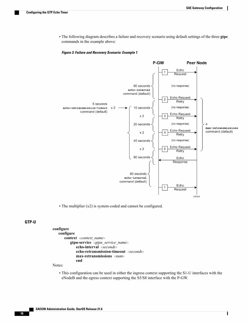
• The following diagram describes a failure and recovery scenario using default settings of the three gtpccommands in the example above:
Figure 3: Failure and Recovery Scenario: Example 1
• The multiplier (x2) is system-coded and cannot be configured.
GTP-U
configureconfigure
context <context_name>gtpu-service <gtpu_service_name>
echo-interval <seconds>echo-retransmission-timeout <seconds>max-retransmissions <num>end
Notes:
• This configuration can be used in either the ingress context supporting the S1-U interfaces with theeNodeB and the egress context supporting the S5/S8 interface with the P-GW.
SAEGW Administration Guide, StarOS Release 21.616
SAE Gateway ConfigurationConfiguring the GTP Echo Timer

• Service names must be unique across all contexts within a chassis.
• The following diagram describes a failure and recovery scenario using default settings of the threeGTP-U commands in the example above:
Figure 4: Failure and Recovery Scenario: Example 2
• The multiplier (x2) is system-coded and cannot be configured.
Dynamic GTP Echo Timer ConfigurationThe following examples describe the configuration of the dynamic eGTP-C and GTP-U interface echo timers:
eGTP-C
configureconfigure
context <context_name>egtp-service <egtp_service_name>
gtpc echo-interval <seconds> dynamic smooth-factor <multiplier>gtpc echo-retransmission-timeout <seconds>
SAEGW Administration Guide, StarOS Release 21.6 17
SAE Gateway ConfigurationConfiguring the GTP Echo Timer

gtpc max-retransmissions <num>end
Notes:
• This configuration can be used in either the ingress context supporting the S1-U and/or S11 interfaceswith the eNodeB and MME respectively; and the egress context supporting the S5/S8 interface with theP-GW.
• Service names must be unique across all contexts within a chassis.
• The following diagram describes a failure and recovery scenario using default settings of the three gtpccommands in the example above and an example round trip timer (RTT) of six seconds:
Figure 5: Failure and Recovery Scenario: Example 3
• The multiplier (x2) and the 100 second maximum are system-coded and cannot be configured.
SAEGW Administration Guide, StarOS Release 21.618
SAE Gateway ConfigurationConfiguring the GTP Echo Timer

GTP-U
configureconfigure
context <context_name>gtpu-service <gtpu_service_name>
echo-interval <seconds> dynamic smooth-factor <multiplier>echo-retransmission-timeout <seconds>max-retransmissions <num>end
Notes:
• This configuration can be used in either the ingress context supporting the S1-U interfaces with theeNodeB and the egress context supporting the S5/S8 interface with the P-GW.
• Service names must be unique across all contexts within a chassis.
SAEGW Administration Guide, StarOS Release 21.6 19
SAE Gateway ConfigurationConfiguring the GTP Echo Timer

• The following diagram describes a failure and recovery scenario using default settings of the three gtpucommands in the example above and an example round trip timer (RTT) of six seconds:
Figure 6: Failure and Recovery Scenario: Example 4
• The multiplier (x2) and the 100 second maximum are system-coded and cannot be configured.
SAEGW Administration Guide, StarOS Release 21.620
SAE Gateway ConfigurationConfiguring the GTP Echo Timer

Configuring GTPP Offline Accounting on the S-GWBy default the S-GW service supports GTPP accounting. To provide GTPP offline charging during, forexample, scenarios where the foreign P-GW does not, configure the S-GW with the example parametersbelow:configure
gtpp single-sourcecontext <saegw_context_name>
subscriber defaultaccounting mode gtppexitgtpp group default
gtpp charging-agent address <gz_ipv4_address>gtpp echo-interval <seconds>gtpp attribute diagnosticsgtpp attribute local-record-sequence-numbergtpp attribute node-id-suffix <string>gtpp dictionary <name>gtpp server <ipv4_address> priority <num>gtpp server <ipv4_address> priority <num> node-alive enableexit
policy accounting <gz_policy_name>accounting-level {type}operator-string <string>cc profile <index> buckets <num>cc profile <index> interval <seconds>cc profile <index> volume total <octets>exit
sgw-service <sgw_service_name>accounting context <saegw_context_name> gtpp group defaultassociate accounting-policy <gz_policy_name>exit
exitcontext <saegw_context_name>
interface <gz_interface_name>ip address <address>exit
exitport ethernet <slot_number/port_number>
no shutdownbind interface <gz_interface_name> <saegw_context_name>end
Notes:
• gtpp single-source is enabled to allow the system to generate requests to the accounting server using asingle UDP port (by way of a AAA proxy function) rather than each AAA manager generating requestson unique UDP ports.
• gtpp is the default option for the accounting mode command.
• An accounting mode configured for the call-control profile will override this setting.
SAEGW Administration Guide, StarOS Release 21.6 21
SAE Gateway ConfigurationConfiguring GTPP Offline Accounting on the S-GW

• accounting-level types are: flow, PDN, PDN-QCI, QCI, and subscriber. Refer to the Accounting ProfileConfigurationMode Commands chapter in theCommand Line Interface Reference for more informationon this command.
• Service names must be unique across all contexts within a chassis.
Configuring Diameter Offline Accounting on the S-GWBy default the S-GW service supports GTPP accounting. You can enable accounting via RADIUS/Diameter(Rf) for the S-GW service. To provide Rf offline charging during, for example, scenarios where the foreignP-GW does not, configure the S-GW with the example parameters below:
In StarOS 19 and later versions, this feature is not supported on the S-GW.Important
configureoperator-policy name <policy_name>
associate call-control-profile <call_cntrl_profile_name>exit
call-control-profile <call_cntrl_profile_name>accounting mode radius-diameter
exitlte-policy
subscriber-map <map_name>precendence <number> match-criteria all operator-policy-name <policy_name>exit
exitcontext <saegw_context_name>
policy accounting <rf_policy_name>accounting-level {type}operator-string <string>exit
sgw-service <sgw_service_name>associate accounting-policy <rf_policy_name>associate subscriber-map <map_name>exit
aaa group <rf-radius_group_name>radius attribute nas-identifier <id>radius accounting interim interval <seconds>radius dictionary <name>radius mediation-device accounting server <address> key <key>diameter authentication dictionary <name>diameter accounting dictionary <name>diameter accounting endpoint <rf_cfg_name>diameter accounting server <rf_cfg_name> priority <num>exit
diameter endpoint <rf_cfg_name>use-proxyorigin realm <realm_name>origin host <name> address <rf_ipv4_address>peer <rf_cfg_name> realm <name> address <ofcs_ipv4_or_ipv6_addr>route-entry peer <rf_cfg_name>exit
SAEGW Administration Guide, StarOS Release 21.622
SAE Gateway ConfigurationConfiguring Diameter Offline Accounting on the S-GW

exitcontext <saegw_context_name>
interface <rf_interface_name>ip address <rf_ipv4_address>exit
exitport ethernet <slot_number/port_number>
no shutdownbind interface <rf_interface_name> <saegw_context_name>end
Notes:
• accounting-level types are: flow, PDN, PDN-QCI, QCI, and subscriber. Refer to the Accounting ProfileConfigurationMode Commands chapter in theCommand Line Interface Reference for more informationon this command.
• The Rf interface IP address can also be specified as an IPv6 address using the ipv6 address command.
• Service names must be unique across all contexts within a chassis.
Configuring APN-level Traffic Policing on the S-GWTo enable traffic policing for scenarios where the foreign subscriber's P-GWdoesn't enforce it, use the followingconfiguration example:configure
apn-profile <apn_profile_name>qos rate-limit downlink non-gbr-qci committed-auto-readjust duration <seconds> exceed-action
{action} violate-action {action}qos rate-limit uplink non-gbr-qci committed-auto-readjust duration <seconds> exceed-action
{action} violate-action {action}exit
operator-policy name <policy_name>apn default-apn-profile <apn_profile_name>exit
lte-policysubscriber-map <map_name>
precendence <number> match-criteria all operator-policy-name <policy_name>exit
sgw-service <sgw_service_name>associate subscriber-map <map_name>end
Notes:
• For the qos rate-limit command, the actions supported for violate-action and exceed-action are: drop,lower-ip-precedence, and transmit.
• Service names must be unique across all contexts within a chassis.
Configuring X.509 Certificate-based Peer AuthenticationThe configuration example in this section enables X.509 certificate-based peer authentication, which can beused as the authentication method for IP Security on the S-GW.
SAEGW Administration Guide, StarOS Release 21.6 23
SAE Gateway ConfigurationConfiguring APN-level Traffic Policing on the S-GW

Use of the IP Security feature requires that a valid license key be installed. Contact your local Sales orSupport representative for information on how to obtain a license.
Important
The following configuration example enables X.509 certificate-based peer authentication on the S-GW.
In Global Configuration Mode, specify the name of the X.509 certificate and CA certificate, as follows:configure
certificate name <cert_name> pem url <cert_pem_url> private-key pem url <private_key_url>ca-certificate name <ca_cert_name> pem url <ca_cert_url>end
Notes:
• The certificate name and ca-certificate list ca-cert-name commands specify the X.509 certificate andCA certificate to be used.
• The PEM-formatted data for the certificate and CA certificate can be specified, or the information canbe read from a file via a specified URL as shown in this example.
When creating the crypto template for IPSec in Context Configuration Mode, bind the X.509 certificate andCA certificate to the crypto template and enable X.509 certificate-based peer authentication for the local andremote nodes, as follows:configure
context <saegw_context_name>crypto template <crypto_template_name> ikev2-dynamic
certificate name <cert_name>ca-certificate list ca-cert-name <ca_cert_name>authentication local certificateauthentication remote certificateend
Notes:
• Amaximum of sixteen certificates and sixteen CA certificates are supported per system. One certificateis supported per service, and a maximum of four CA certificates can be bound to one crypto template.
• The certificate name and ca-certificate list ca-cert-name commands bind the certificate and CAcertificate to the crypto template.
• The authentication local certificate and authentication remote certificate commands enable X.509certificate-based peer authentication for the local and remote nodes.
• Service names must be unique across all contexts within a chassis.
Configuring Dynamic Node-to-Node IP Security on the S1-U and S5 InterfacesThe configuration example in this section creates IPSec/IKEv2 dynamic node-to-node tunnel endpoints onthe S1-U and S5 interfaces.
Use of the IP Security feature requires that a valid license key be installed. Contact your local Sales orSupport representative for information on how to obtain a license.
Important
SAEGW Administration Guide, StarOS Release 21.624
SAE Gateway ConfigurationConfiguring Dynamic Node-to-Node IP Security on the S1-U and S5 Interfaces

The following configuration examples are included in this section:
• Creating and Configuring an IPSec Transform Set, on page 25
• Creating and Configuring an IKEv2 Transform Set, on page 25
• Creating and Configuring a Crypto Template, on page 26
• Binding the S1-U and S5 IP Addresses to the Crypto Template, on page 26
Creating and Configuring an IPSec Transform SetThe following example configures an IPSec transform set, which is used to define the security associationthat determines the protocols used to protect the data on the interface:configure
context <saegw_context_name>ipsec transform-set <ipsec_transform-set_name>
encryption aes-cbc-128group nonehmac sha1-96mode tunnelend
Notes:
• The encryption algorithm, aes-cbc-128, or Advanced Encryption Standard Cipher Block Chaining, isthe default algorithm for IPSec transform sets configured on the system.
• The group none command specifies that no crypto strength is included and that Perfect Forward Secrecyis disabled. This is the default setting for IPSec transform sets configured on the system.
• The hmac command configures the Encapsulating Security Payload (ESP) integrity algorithm. Thesha1-96 keyword uses a 160-bit secret key to produce a 160-bit authenticator value. This is the defaultsetting for IPSec transform sets configured on the system.
• Themode tunnel command specifies that the entire packet is to be encapsulated by the IPSec header,including the IP header. This is the default setting for IPSec transform sets configured on the system.
• Service names must be unique across all contexts within a chassis.
Creating and Configuring an IKEv2 Transform SetThe following example configures an IKEv2 transform set:configure
context <saegw_context_name>ikev2-ikesa transform-set <ikev2_transform-set_name>
encryption aes-cbc-128group 2hmac sha1-96lifetime <sec>prf sha1end
Notes:
SAEGW Administration Guide, StarOS Release 21.6 25
SAE Gateway ConfigurationConfiguring Dynamic Node-to-Node IP Security on the S1-U and S5 Interfaces

• The encryption algorithm, aes-cbc-128, or Advanced Encryption Standard Cipher Block Chaining, isthe default algorithm for IKEv2 transform sets configured on the system.
• The group 2 command specifies the Diffie-Hellman algorithm as Group 2, indicating medium security.The Diffie-Hellman algorithm controls the strength of the crypto exponentials. This is the default settingfor IKEv2 transform sets configured on the system.
• The hmac command configures the Encapsulating Security Payload (ESP) integrity algorithm. Thesha1-96 keyword uses a 160-bit secret key to produce a 160-bit authenticator value. This is the defaultsetting for IKEv2 transform sets configured on the system.
• The lifetime command configures the time the security key is allowed to exist, in seconds.
• The prf command configures the IKE Pseudo-random Function, which produces a string of bits thatcannot be distinguished from a random bit string without knowledge of the secret key. The sha1 keyworduses a 160-bit secret key to produce a 160-bit authenticator value. This is the default setting for IKEv2transform sets configured on the system.
• Service names must be unique across all contexts within a chassis.
Creating and Configuring a Crypto TemplateThe following example configures an IKEv2 crypto template:configure
context <saegw_context_name>crypto template <crypto_template_name> ikev2-dynamic
ikev2-ikesa transform-set list <name1> . . . <name6>ikev2-ikesa rekeypayload <name> match childsa match ipv4
ipsec transform-set list <name1> . . . <name4>rekeyend
Notes:
• The ikev2-ikesa transform-set list command specifies up to six IKEv2 transform sets.
• The ipsec transform-set list command specifies up to four IPSec transform sets.
• Service names must be unique across all contexts within a chassis.
Binding the S1-U and S5 IP Addresses to the Crypto TemplateThe following example configures the binding of the S1-U and S5 interfaces to the crypto template.configure
context <saegw_context_name>gtpu-service <gtpu_ingress_service_name>
bind ipv4-address <s1-u_interface_ip_address> crypto-template <enodeb_crypto_template>exit
egtp-service <egtp_ingress_service_name>interface-type interface-sgw-ingressassociate gtpu-service <gtpu_ingress_service_name>gtpc bind address <s1u_interface_ip_address>exit
exit
SAEGW Administration Guide, StarOS Release 21.626
SAE Gateway ConfigurationConfiguring Dynamic Node-to-Node IP Security on the S1-U and S5 Interfaces

context <sgw_egress_context_name>gtpu-service <gtpu_egress_service_name>
bind ipv4-address <s5_interface_ip_address> crypto-template <enodeb_crypto_template>exit
egtp-service <egtp_egress_service_name>interface-type interface-sgw-egressassociate gtpu-service <gtpu_egress_service_name>gtpc bind address <s5_interface_ip_address>exit
exitcontext <saegw_context_name>
sgw-service <sgw_service_name> -noconfirmegtp-service ingress service <egtp_ingress_service_name>egtp-service egress context <sgw_egress_context_name>end
Notes:
• The bind command in the GTP-U ingress and egress service configuration can also be specified as anIPv6 address using the ipv6-address command.
• Service names must be unique across all contexts within a chassis.
Configuring ACL-based Node-to-Node IP Security on the S1-U and S5 InterfacesThe configuration example in this section creates IKEv2/IPSec ACL-based node-to-node tunnel endpointson the S1-U and S5 interfaces.
Use of the IP Security feature requires that a valid license key be installed. Contact your local Sales orSupport representative for information on how to obtain a license.
Important
The following configuration examples are included in this section:
• Creating and Configuring a Crypto Access Control List, on page 27
• Creating and Configuring an IPSec Transform Set, on page 28
• Creating and Configuring an IKEv2 Transform Set, on page 28
• Creating and Configuring a Crypto Map, on page 29
Creating and Configuring a Crypto Access Control ListThe following example configures a crypto ACL (Access Control List), which defines the matching criteriaused for routing subscriber data packets over an IPSec tunnel:configure
context <saegw_context_name>ip access-list <acl_name>
permit tcp host <source_host_address> host <dest_host_address>end
Notes:
SAEGW Administration Guide, StarOS Release 21.6 27
SAE Gateway ConfigurationConfiguring ACL-based Node-to-Node IP Security on the S1-U and S5 Interfaces

• The permit command in this example routes IPv4 traffic from the server with the specified source hostIPv4 address to the server with the specified destination host IPv4 address.
Creating and Configuring an IPSec Transform SetThe following example configures an IPSec transform set which is used to define the security association thatdetermines the protocols used to protect the data on the interface:configure
context <saegw_context_name>ipsec transform-set <ipsec_transform-set_name>
encryption aes-cbc-128group nonehmac sha1-96mode tunnelend
Notes:
• The encryption algorithm, aes-cbc-128, or Advanced Encryption Standard Cipher Block Chaining, isthe default algorithm for IPSec transform sets configured on the system.
• The group none command specifies that no crypto strength is included and that Perfect Forward Secrecyis disabled. This is the default setting for IPSec transform sets configured on the system.
• The hmac command configures the Encapsulating Security Payload (ESP) integrity algorithm. Thesha1-96 keyword uses a 160-bit secret key to produce a 160-bit authenticator value. This is the defaultsetting for IPSec transform sets configured on the system.
• Themode tunnel command specifies that the entire packet is to be encapsulated by the IPSec headerincluding the IP header. This is the default setting for IPSec transform sets configured on the system.
• Service names must be unique across all contexts within a chassis.
Creating and Configuring an IKEv2 Transform SetThe following example configures an IKEv2 transform set:configure
context <saegw_context_name>ikev2-ikesa transform-set <ikev2_transform-set_name>
encryption aes-cbc-128group 2hmac sha1-96lifetime <sec>prf sha1end
Notes:
• The encryption algorithm, aes-cbc-128, or Advanced Encryption Standard Cipher Block Chaining, isthe default algorithm for IKEv2 transform sets configured on the system.
• The group 2 command specifies the Diffie-Hellman algorithm as Group 2, indicating medium security.The Diffie-Hellman algorithm controls the strength of the crypto exponentials. This is the default settingfor IKEv2 transform sets configured on the system.
SAEGW Administration Guide, StarOS Release 21.628
SAE Gateway ConfigurationConfiguring ACL-based Node-to-Node IP Security on the S1-U and S5 Interfaces

• The hmac command configures the Encapsulating Security Payload (ESP) integrity algorithm. Thesha1-96 keyword uses a 160-bit secret key to produce a 160-bit authenticator value. This is the defaultsetting for IKEv2 transform sets configured on the system.
• The lifetime command configures the time the security key is allowed to exist, in seconds.
• The prf command configures the IKE Pseudo-random Function which produces a string of bits thatcannot be distinguished from a random bit string without knowledge of the secret key. The sha1 keyworduses a 160-bit secret key to produce a 160-bit authenticator value. This is the default setting for IKEv2transform sets configured on the system.
• Service names must be unique across all contexts within a chassis.
Creating and Configuring a Crypto MapThe following example configures an IKEv2 crypto map and applies it to the S1-U interface:configure
context <saegw_context_name>crypto map <crypto_map_name> ikev2-ipv4
match address <acl_name>peer <ipv4_address>authentication local pre-shared-key key <text>authentication remote pre-shared-key key <text>ikev2-ikesa transform-set list <name1> . . . <name6>payload <name> match ipv4
lifetime <seconds>ipsec transform-set list <name1> . . . <name4>exit
exitinterface <s1-u_intf_name>
ip address <ipv4_address>crypto-map <crypto_map_name>
exitexitport ethernet <slot_number/port_number>
no shutdownbind interface <s1_u_intf_name> <saegw_context_name>end
Notes:
• The type of crypto map used in this example is IKEv2-IPv4 for IPv4 addressing. An IKEv2-IPv6 cryptomap can also be used for IPv6 addressing.
• The ipsec transform-set list command specifies up to four IPSec transform sets.
• Service names must be unique across all contexts within a chassis.
The following example configures an IKEv2 crypto map and applies it to the S5 interface:configure
context <sgw_egress_context_name>crypto map <crypto_map_name> ikev2-ipv4
match address <acl_name>peer <ipv4_address>authentication local pre-shared-key key <text>
SAEGW Administration Guide, StarOS Release 21.6 29
SAE Gateway ConfigurationConfiguring ACL-based Node-to-Node IP Security on the S1-U and S5 Interfaces

authentication remote pre-shared-key key <text>payload <name> match ipv4
lifetime <seconds>ipsec transform-set list <name1> . . . <name4>exit
exitinterface <s5_intf_name>
ip address <ipv4_address>crypto map <crypto_map_name>exit
exitport ethernet <slot_number/port_number>
no shutdownbind interface <s5_intf_name> <sgw_egress_context_name>end
Notes:
• The type of crypto map used in this example is IKEv2-IPv4 for IPv4 addressing. An IKEv2-IPv6 cryptomap can also be used for IPv6 addressing.
• The ipsec transform-set list command specifies up to four IPSec transform sets.
• Service names must be unique across all contexts within a chassis.
Configuring R12 Load Control SupportLoad control enables a GTP-C entity (for example, an S-GW/P-GW) to send its load information to a GTP-Cpeer (e.g. an MME/SGSN, ePDG, TWAN) to adaptively balance the session load across entities supportingthe same function (for example, an S-GW cluster) according to their effective load. The load informationreflects the operating status of the resources of the GTP-C entity.
Use the following example to configure this feature:configure
gtpc-load-control-profile profile_nameinclusion-frequency advertisement-interval interval_in_secondsweightage system-cpu-utilization percentage system-memory-utilization percentage
license-session-utilization percentageend
configurecontext context_name
sgw-service sgw_service_nameassociate gtpc-load-control-profile profile_nameexit
saegw-service saegw_service_nameassociate sgw-service sgw_service_nameend
Notes:
• The inclusion-frequency parameter determines how often the Load control information element is sentto the peer(s).
• The total of the three weightage parameters should not exceed 100.
• The associate command is used to associate the Load Control Profile with an existing S-GW serviceand to associate the S-GW service with the SAEGW service.
SAEGW Administration Guide, StarOS Release 21.630
SAE Gateway ConfigurationConfiguring R12 Load Control Support

• On the SAEGW, both the P-GW and S-GW should use the same Load Control profile.
Configuring R12 Overload Control SupportOverload control enables a GTP-C entity becoming or being overloaded to gracefully reduce its incomingsignaling load by instructing its GTP-C peers to reduce sending traffic according to its available signalingcapacity to successfully process the traffic. A GTP-C entity is in overload when it operates over its signalingcapacity, which results in diminished performance (including impacts to handling of incoming and outgoingtraffic).
Use the following example to configure this feature.configure
gtpc-overload-control-profile profile_nameinclusion-frequency advertisement-interval interval_in_secondsweightage system-cpu-utilization percentage system-memory-utilization percentage
license-session-utilization percentagethrottling-behavior emergency-events excludetolerance initial-reduction-metric percentagetolerance threshold report-reduction-metric percentage self-protection-limit percentagevalidity-period secondsend
configurecontext context_name
sgw-service sgw_service_nameassociate gtpc-overload-control-profile profile_nameexit
saegw-service saegw_service_nameassociate sgw-service sgw_service_nameend
Notes:
• The inclusion-frequency parameter determines how often the Overload control information element issent to the peer(s).
• The total of the three weightage parameters should not exceed 100.
• validity-period configures how long the overload control information is valid. Valid entries are from1 to 3600 seconds. The default is 600 seconds.
• The associate command is used to associate the Overload Control Profile with an existing S-GW andSAEGW service.
• On the SAEGW, both the P-GW and S-GW should use the same Overload Control profile.
Configuring S4 SGSN Handover CapabilityThis configuration example configures an S4 interface supporting inter-RAT handovers between the S-GWand a S4 SGSN.
Use the following example to configure this feature:configure
context <saegw_context_name> -noconfirm
SAEGW Administration Guide, StarOS Release 21.6 31
SAE Gateway ConfigurationConfiguring R12 Overload Control Support

interface <s4_interface_name>ip address <ipv4_address_primary>ip address <ipv4_address_secondary>exit
exitport ethernet <slot_number/port_number>
no shutdownbind interface <s4_interface_name> <saegw_context_name>exit
context <saegw_context_name> -noconfirmgtpu-service <s4_gtpu_ingress_service_name>
bind ipv4-address <s4_interface_ip_address>exit
egtp-service <s4_egtp_ingress_service_name>interface-type interface-sgw-ingressvalidation-mode defaultassociate gtpu-service <s4_gtpu_ingress_service_name>gtpc bind address <s4_interface_ip_address>exit
sgw-service <sgw_service_name> -noconfirmassociate ingress egtp-service <s4_egtp_ingress_service_name>end
Notes:
• The S4 interface IP address(es) can also be specified as IPv6 addresses using the ipv6 address command.
• Service names must be unique across all contexts within a chassis.
Configuring an eGTP P-GW ServiceThis section provides a high-level series of steps and the associated configuration file examples for configuringthe system to perform as an eGTP P-GW in a test environment. Information provided in this section includesthe following:
• Information Required, on page 32
• How This Configuration Works, on page 40
• eGTP P-GW Configuration, on page 42
• DHCP Service Creation, on page 53
• DHCPv6 Service Creation, on page 55
Information RequiredThe following sections describe the minimum amount of information required to configure and make theP-GW operational on the network. To make the process more efficient, it is recommended that this informationbe available prior to configuring the system.
There are additional configuration parameters that are not described in this section. These parameters dealmostly with fine-tuning the operation of the P-GW in the network. Information on these parameters can befound in the appropriate sections of the Command Line Interface Reference.
SAEGW Administration Guide, StarOS Release 21.632
SAE Gateway ConfigurationConfiguring an eGTP P-GW Service

Required P-GW Context Configuration InformationThe following table lists the information that is required to configure the P-GW context on a P-GW.
Table 5: Required Information for P-GW (SAEGW) Context Configuration
DescriptionRequired Information
An identification string from 1 to 79 characters (alpha and/or numeric) bywhich the P-GW context will be recognized by the system.
The P-GW service must reside within the SAEGW context,thus this would be the SAEGW context name.
Important
P-GW context name
An identification string from 1 to 63 characters (alpha and/or numeric) bywhich the accounting policy will be recognized by the system. Theaccounting policy is used to set parameters for the Rf (off-line charging)interface.
Accounting policy name
S5/S8 Interface Configuration (To/from S-GW)
An identification string between 1 and 79 characters (alpha and/or numeric)by which the interface will be recognized by the system.
Multiple names are needed if multiple interfaces will be configured.
Interface name
IPv4 or IPv6 addresses assigned to the interface.
Multiple addresses and subnets are needed if multiple interfaces will beconfigured.
IP address and subnet
The physical port to which the interface will be bound. Ports are identifiedby the chassis slot number where the line card resides followed by thenumber of the physical connector on the card. For example, port 17/1identifies connector number 1 on the card in slot 17.
A single physical port can facilitate multiple interfaces.
Physical port number
Used when configuring static IP routes from the interface(s) to a specificnetwork.
Gateway IP address
GTP-U Service Configuration
An identification string from 1 to 63 characters (alpha and/or numeric) bywhich the GTP-U service will be recognized by the system.
GTP-U service name
S5/S8 interface IPv4 address.IP address
P-GW Service Configuration
SAEGW Administration Guide, StarOS Release 21.6 33
SAE Gateway ConfigurationInformation Required

DescriptionRequired Information
An identification string from 1 to 63 characters (alpha and/or numeric) bywhich the P-GW service will be recognized by the system.
Multiple names are needed if multiple P-GW services will be used.
P-GW service name
MCC number: The mobile country code (MCC) portion of the PLMN'sidentifier (an integer value between 100 and 999).
MNC number: The mobile network code (MNC) portion of the PLMN'sidentifier (a 2 or 3 digit integer value between 00 and 999).
PLMN ID
eGTP Service Configuration
An identification string from 1 to 63 characters (alpha and/or numeric) bywhich the eGTP service will be recognized by the system.
eGTP Service Name
Required PDN Context Configuration InformationThe following table lists the information that is required to configure the PDN context on a P-GW.
Table 6: Required Information for PDN Context Configuration
DescriptionRequired Information
An identification string from 1 to 79 characters (alpha and/or numeric) bywhich the PDN context is recognized by the system.
PDN context name
IP Address Pool Configuration
An identification string between 1 and 31 characters (alpha and/or numeric)by which the IPv4 pool is recognized by the system.
Multiple names are needed if multiple pools will be configured.
A range of IPv4 addresses defined by a starting address and an endingaddress.
IPv4 address pool name andrange
An identification string between 1 and 31 characters (alpha and/or numeric)by which the IPv6 pool is recognized by the system.
Multiple names are needed if multiple pools will be configured.
A range of IPv6 addresses defined by a starting address and an endingaddress.
IPv6 address pool name andrange
Access Control List Configuration
An identification string between 1 and 47 characters (alpha and/or numeric)by which the IPv4 access list is recognized by the system.
Multiple names are needed if multiple lists will be configured.
IPv4 access list name
SAEGW Administration Guide, StarOS Release 21.634
SAE Gateway ConfigurationInformation Required

DescriptionRequired Information
An identification string between 1 and 79 characters (alpha and/or numeric)by which the IPv6 access list is recognized by the system.
Multiple names are needed if multiple lists will be configured.
IPv6 access list name
The types are:
• any
• by host IP address
• by IP packets
• by source ICMP packets
• by source IP address masking
• by TCP/UDP packets
Deny/permit type
The types are
• readdress server
• redirect context
• redirect css delivery-sequence
• redirect css service
• redirect nexthop
Readdress or redirect type
SGi Interface Configuration (To/from IPv4 PDN)
An identification string between 1 and 79 characters (alpha and/or numeric)by which the interface is recognized by the system.
Multiple names are needed if multiple interfaces will be configured.
Interface name
IPv4 addresses assigned to the interface.
Multiple addresses and subnets are needed if multiple interfaces will beconfigured.
IP address and subnet
The physical port to which the interface will be bound. Ports are identifiedby the chassis slot number where the line card resides followed by thenumber of the physical connector on the card. For example, port 17/1identifies connector number 1 on the card in slot 17.
A single physical port can facilitate multiple interfaces.
Physical port number
Used when configuring static IP routes from the interface(s) to a specificnetwork.
Gateway IP address
SGi Interface Configuration (To/from IPv6 PDN)
SAEGW Administration Guide, StarOS Release 21.6 35
SAE Gateway ConfigurationInformation Required

DescriptionRequired Information
An identification string between 1 and 79 characters (alpha and/or numeric)by which the interface is recognized by the system.
Multiple names are needed if multiple interfaces will be configured.
Interface name
IPv6 addresses assigned to the interface.
Multiple addresses and subnets are needed if multiple interfaces will beconfigured.
IP address and subnet
The physical port to which the interface will be bound. Ports are identifiedby the chassis slot number where the line card resides followed by thenumber of the physical connector on the card. For example, port 17/1identifies connector number 1 on the card in slot 17.
A single physical port can facilitate multiple interfaces.
Physical port number
Used when configuring static IP routes from the interface(s) to a specificnetwork.
Gateway IP address
Required AAA Context Configuration InformationThe following table lists the information that is required to configure the AAA context on a P-GW.
Table 7: Required Information for AAA Context Configuration
DescriptionRequired Information
Gx Interface Configuration (to PCRF)
An identification string between 1 and 79 characters (alpha and/or numeric)by which the interface is recognized by the system.
Multiple names are needed if multiple interfaces will be configured.
Interface name
IPv4 or IPv6 addresses assigned to the interface.
Multiple addresses and subnets are needed if multiple interfaces will beconfigured.
IP address and subnet
The physical port to which the interface will be bound. Ports are identifiedby the chassis slot number where the line card resides followed by thenumber of the physical connector on the card. For example, port 17/1identifies connector number 1 on the card in slot 17.
A single physical port can facilitate multiple interfaces.
Physical port number
Used when configuring static IP routes from the interface(s) to a specificnetwork.
Gateway IP address
SAEGW Administration Guide, StarOS Release 21.636
SAE Gateway ConfigurationInformation Required

DescriptionRequired Information
Gx Diameter Endpoint Configuration
An identification string from 1 to 63 characters (alpha and/or numeric) bywhich the GxDiameter endpoint configuration is recognized by the system.
End point name
An identification string between 1 through 127 characters.
The realm is the Diameter identity. The originator's realm is present in allDiameter messages and is typically the company or service name.
Origin realm name
An identification string from 1 to 255 characters (alpha and/or numeric)by which the Gx origin host is recognized by the system.
Origin host name
The IP address of the Gx interface.Origin host address
The Gx endpoint name described above.Peer name
The Gx origin realm name described above.Peer realm name
The IP address and port number of the PCRF.Peer address and port number
The Gx endpoint name described above.Route-entry peer
Gy Interface Configuration (to on-line charging server)
An identification string between 1 and 79 characters (alpha and/or numeric)by which the interface is recognized by the system.
Multiple names are needed if multiple interfaces will be configured.
Interface name
IPv4 or IPv6 addresses assigned to the interface.
Multiple addresses and subnets are needed if multiple interfaces will beconfigured.
IP address and subnet
The physical port to which the interface will be bound. Ports are identifiedby the chassis slot number where the line card resides followed by thenumber of the physical connector on the card. For example, port 17/1identifies connector number 1 on the card in slot 17.
A single physical port can facilitate multiple interfaces.
Physical port number
Used when configuring static IP routes from the interface(s) to a specificnetwork.
Gateway IP address
Gy Diameter Endpoint Configuration
An identification string from 1 to 63 characters (alpha and/or numeric) bywhich the GyDiameter endpoint configuration is recognized by the system.
End point name
SAEGW Administration Guide, StarOS Release 21.6 37
SAE Gateway ConfigurationInformation Required
DescriptionRequired Information
An identification string between 1 through 127 characters.
The realm is the Diameter identity. The originator's realm is present in allDiameter messages and is typically the company or service name.
Origin realm name
An identification string from 1 to 255 characters (alpha and/or numeric)by which the Gy origin host is recognized by the system.
Origin host name
The IP address of the Gy interface.Origin host address
The Gy endpoint name described above.Peer name
The Gy origin realm name described above.Peer realm name
The IP address and port number of the OCS.Peer address and port number
The Gy endpoint name described above.Route-entry peer
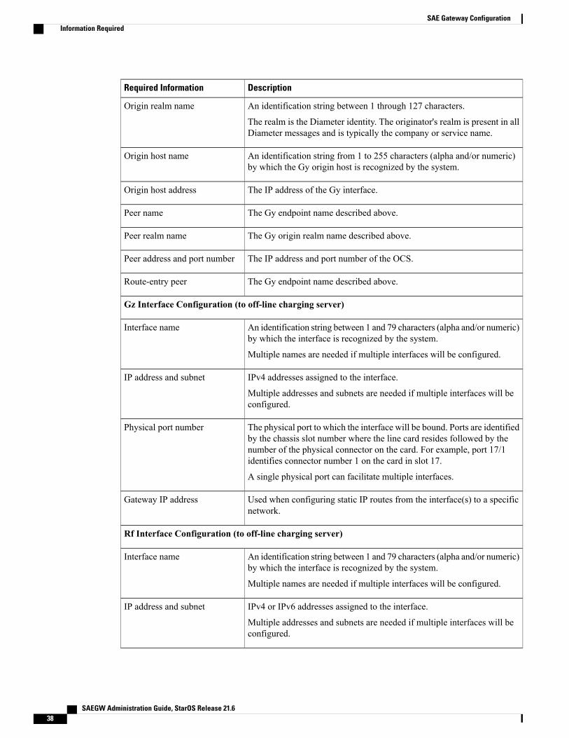
Gz Interface Configuration (to off-line charging server)
An identification string between 1 and 79 characters (alpha and/or numeric)by which the interface is recognized by the system.
Multiple names are needed if multiple interfaces will be configured.
Interface name
IPv4 addresses assigned to the interface.
Multiple addresses and subnets are needed if multiple interfaces will beconfigured.
IP address and subnet
The physical port to which the interface will be bound. Ports are identifiedby the chassis slot number where the line card resides followed by thenumber of the physical connector on the card. For example, port 17/1identifies connector number 1 on the card in slot 17.
A single physical port can facilitate multiple interfaces.
Physical port number
Used when configuring static IP routes from the interface(s) to a specificnetwork.
Gateway IP address
Rf Interface Configuration (to off-line charging server)
An identification string between 1 and 79 characters (alpha and/or numeric)by which the interface is recognized by the system.
Multiple names are needed if multiple interfaces will be configured.
Interface name
IPv4 or IPv6 addresses assigned to the interface.
Multiple addresses and subnets are needed if multiple interfaces will beconfigured.
IP address and subnet
SAEGW Administration Guide, StarOS Release 21.638
SAE Gateway ConfigurationInformation Required

DescriptionRequired Information
The physical port to which the interface will be bound. Ports are identifiedby the chassis slot number where the line card resides followed by thenumber of the physical connector on the card. For example, port 17/1identifies connector number 1 on the card in slot 17.
A single physical port can facilitate multiple interfaces.
Physical port number
Used when configuring static IP routes from the interface(s) to a specificnetwork.
Gateway IP address
Rf Diameter Endpoint Configuration
An identification string from 1 to 63 characters (alpha and/or numeric) bywhich the Rf Diameter endpoint configuration is recognized by the system.
End point name
An identification string between 1 through 127 characters.
The realm is the Diameter identity. The originator's realm is present in allDiameter messages and is typically the company or service name.
Origin realm name
An identification string from 1 to 255 characters (alpha and/or numeric)by which the Rf origin host is recognized by the system.
Origin host name
The IP address of the Rf interface.Origin host address
The Rf endpoint name described above.Peer name
The Rf origin realm name described above.Peer realm name
The IP address and port number of the OFCS.Peer address and port number
The Rf endpoint name described above.Route-entry peer
SAEGW Administration Guide, StarOS Release 21.6 39
SAE Gateway ConfigurationInformation Required

How This Configuration WorksThe following figure and supporting text describe how this configuration with a single source and destinationcontext is used by the system to process a subscriber call originating from the GTP LTE network.
Figure 7: SAEGW Configuration with Single Source and Destination Context Processing a Subscriber Call Originatingfrom the GTP LTE Network
1 The S-GW establishes the S5/S8 connection by sending a Create Session Request message to the P-GWincluding an Access Point name (APN).
2 The P-GW service determines which context to use to provide AAA functionality for the session. Thisprocess is described in the How the System Selects Contexts section located in the Understanding theSystem Operation and Configuration chapter of the System Administration Guide.
3 The P-GW uses the configured Gx Diameter endpoint to establish the IP-CAN session.
4 The P-GW sends a CC-Request (CCR) message to the PCRF to indicate the establishment of the IP-CANsession and the PCRF acknowledges with a CC-Answer (CCA).
SAEGW Administration Guide, StarOS Release 21.640
SAE Gateway ConfigurationHow This Configuration Works

5 The P-GW uses the APN configuration to select the PDN context. IP addresses are assigned from the IPpool configured in the selected PDN context.
6 The P-GW responds to the S-GWwith a Create Session Response message including the assigned addressand additional information.
7 The S5/S8 data plane tunnel is established and the P-GW can forward and receive packets to/from thePDN.
SAEGW Administration Guide, StarOS Release 21.6 41
SAE Gateway ConfigurationHow This Configuration Works

eGTP P-GW ConfigurationTo configure the system to perform as an eGTP P-GW:
Figure 8: eGTP P-GW Configuration
Step 1 Set system configuration parameters such as activating PSCs by applying the example configurations found in the SystemAdministration Guide.
Step 2 Set initial configuration parameters such as creating contexts and services by applying the example configurations foundin Initial Configuration, on page 43.
Step 3 Configure the system to perform as an eGTP P-GW and set basic P-GW parameters such as eGTP interfaces and IProutes by applying the example configurations presented in P-GW Service Configuration, on page 46.
Step 4 Configure the PDN context by applying the example configuration in P-GW PDN Context Configuration, on page 47.Step 5 Enable and configure the active charging service for Gx interface support by applying the example configuration in
Active Charging Service Configuration, on page 48.Step 6 Create a AAA context and configure parameters for policy by applying the example configuration in Policy Configuration,
on page 50.Step 7 Verify and save the configuration by following the steps found in Verifying and Saving the Configuration, on page 52.
SAEGW Administration Guide, StarOS Release 21.642
SAE Gateway ConfigurationeGTP P-GW Configuration

Initial Configuration
Step 1 Create the context where the eGTP service will reside by applying the example configuration in Creating and Configuringan eGTP P-GW Context, on page 43.
Step 2 Create and configure APNs in the P-GW context by applying the example configuration in Creating and ConfiguringAPNs in the P-GW Context, on page 44.
Step 3 Create and configure AAA server groups in the P-GW context by applying the example configuration in Creating andConfiguring AAA Groups in the P-GW Context, on page 45.
Step 4 Create an eGTP service within the newly created context by applying the example configuration in Creating andConfiguring an eGTP Service, on page 45.
Step 5 Create and configure a GTP-U service within the P-GW context by applying the example configuration in Creating andConfiguring a GTP-U Service, on page 46.
Step 6 Create a context through which the interface to the PDN will reside by applying the example configuration in Creatinga P-GW PDN Context, on page 46.
Creating and Configuring an eGTP P-GW Context
Use the following example to create a P-GW context, create an S5/S8 IPv4 interface (for data traffic to/fromthe S-GW), and bind the S5/S8 interface to a configured Ethernet port:configure
gtpp single-sourcecontext <saegw_context_name> -noconfirm
interface <s5s8_interface_name>ip address <ipv4_address>exit
gtpp group defaultgtpp charging-agent address <gz_ipv4_address>gtpp echo-interval <seconds>gtpp attribute diagnosticsgtpp attribute local-record-sequence-numbergtpp attribute node-id-suffix <string>gtpp dictionary <name>gtpp server <ipv4_address> priority <num>gtpp server <ipv4_address> priority <num> node-alive enableexit
policy accounting <rf_policy_name> -noconfirmaccounting-level {level_type}accounting-event-trigger interim-timeout action stop-startoperator-string <string>cc profile <index> interval <seconds>exit
exitsubscriber defaultexitport ethernet <slot_number/port_number>
no shutdown
SAEGW Administration Guide, StarOS Release 21.6 43
SAE Gateway ConfigurationeGTP P-GW Configuration
bind interface <s5s8_interface_name> <saegw_context_name>end
Notes:
• gtpp single-source is enabled to allow the system to generate requests to the accounting server using asingle UDP port (by way of a AAA proxy function) rather than each AAA manager generating requestson unique UDP ports.
• The S5/S8 (P-GW to S-GW) interface IP address can also be specified as an IPv6 address using the ipv6address command.
• Set the accounting policy for the Rf (off-line charging) interface. The accounting level types are: flow,PDN, PDN-QCI, QCI, and subscriber. Refer to the Accounting Profile Configuration Mode Commandschapter in the Command Line Interface Reference for more information on this command.
• Set the GTPP group setting for Gz accounting.
• Service names must be unique across all contexts within a chassis.
Creating and Configuring APNs in the P-GW Context
Use the following configuration to create an APN:configure
context <saegw_context_name> -noconfirmapn <name>
accounting-mode radius-diameterassociate accounting-policy <rf_policy_name>ims-auth-service <gx_ims_service_name>aaa group <rf-radius_group_name>dns primary <ipv4_address>dns secondary <ipv4_address>ip access-group <name> inip access-group <name> outmediation-device context-name <saegw_context_name>ip context-name <pdn_context_name>ipv6 access-group <name> inipv6 access-group <name> outactive-charging rulebase <name>end
Notes:
• The IMS Authorization Service is created and configured in the AAA context.
• Multiple APNs can be configured to support different domain names.
• The associate accounting-policy command is used to associate a pre-configured accounting policy withthis APN. Accounting policies are configured in the P-GW context. An example is located in Creatingand Configuring an eGTP P-GW Context, on page 43.
• Service names must be unique across all contexts within a chassis.
Use the following configuration to create an APN that includes Gz interface parameters:configure
context <saegw_context_name> -noconfirmapn <name>
SAEGW Administration Guide, StarOS Release 21.644
SAE Gateway ConfigurationeGTP P-GW Configuration

bearer-control-mode mixedselection-mode sent-by-msaccounting-mode gtppgtpp group default accounting-context <aaa_context_name>ims-auth-service <gx_ims_service_name>ip access-group <name> inip access-group <name> outip context-name <pdn_context_name>active-charging rulebase <gz_rulebase_name>end
Notes:
• The IMS Authorization Service is created and configured in the AAA context.
• Multiple APNs can be configured to support different domain names.
• The accounting-mode GTPP and GTPP group commands configure this APN for Gz accounting.
• Service names must be unique across all contexts within a chassis.
Creating and Configuring AAA Groups in the P-GW Context
Use the following example to create and configure AAA groups supporting RADIUS and Rf accounting:configure
context <saegw_context_name> -noconfirmaaa group <rf-radius_group_name>
radius attribute nas-identifier <id>radius accounting interim interval <seconds>radius dictionary <name>radius mediation-device accounting server <address> key <key>diameter authentication dictionary <name>diameter accounting dictionary <name>diameter accounting endpoint <rf_cfg_name>diameter accounting server <rf_cfg_name> priority <num>exit
aaa group defaultradius attribute nas-ip-address address <ipv4_address>radius accounting interim interval <seconds>diameter authentication dictionary <name>diameter accounting dictionary <name>diameter accounting endpoint <rf_cfg_name>diameter accounting server <rf_cfg_name> priority <num>end
Notes:
• Service names must be unique across all contexts within a chassis.
Creating and Configuring an eGTP Service
Use the following configuration example to create the eGTP service:configure
context <saegw_context_name>egtp-service <egtp_service_name> -noconfirm
interface-type interface-pgw-ingress
SAEGW Administration Guide, StarOS Release 21.6 45
SAE Gateway ConfigurationeGTP P-GW Configuration

validation mode defaultassociate gtpu-service <gtpu_service_name>gtpc bind address <s5s8_interface_address>end
Notes:
• Co-locating a GGSN service on the same ASR 5500 requires that the gtpc bind address command usesthe same IP address the GGSN service is bound to.
• Service names must be unique across all contexts within a chassis.
Creating and Configuring a GTP-U Service
Use the following configuration example to create the GTP-U service:configure
context <saegw_context_name>gtpu-service <gtpu_service_name> -noconfirm
bind ipv4-address <s5s8_interface_address>end
Notes:
• The bind command can also be specified as an IPv6 address using the ipv6-address command.
• Service names must be unique across all contexts within a chassis.
Creating a P-GW PDN Context
Use the following example to create a P-GW PDN context and Ethernet interface, and bind the interface to aconfigured Ethernet port.configure
context <pdn_context_name> -noconfirminterface <sgi_ipv4_interface_name>
ip address <ipv4_address>exit
interface <sgi_ipv6_interface_name>ipv6 address <address>end
Notes:
• Service names must be unique across all contexts within a chassis.
P-GW Service Configuration
Step 1 Configure the P-GW service by applying the example configuration in Configuring the P-GW Service, on page 47.Step 2 Specify an IP route to the eGTP Serving Gateway by applying the example configuration in Configuring a Static IP
Route, on page 47.
SAEGW Administration Guide, StarOS Release 21.646
SAE Gateway ConfigurationeGTP P-GW Configuration

Configuring the P-GW Service
Use the following example to configure the P-GW service:configure
context <saegw_context_name>pgw-service <pgw_service_name> -noconfirm
plmn id mcc <id> mnc <id>associate egtp-service <egtp_service_name>associate qci-qos-mapping <name>end
Notes:
• QCI-QoS mapping configurations are created in the AAA context. Refer to Configuring QCI-QoSMapping, on page 51.
• Co-locating a GGSN service on the same ASR 5500 requires the configuration of the associateggsn-service name command within the P-GW service.
• Service names must be unique across all contexts within a chassis.
Configuring a Static IP Route
Use the following example to configure an IP Route for control and user plane data communication with aneGTP Serving Gateway:configure
context <saegw_context_name>ip route <sgw_ip_addr/mask> <sgw_next_hop_addr> <pgw_intrfc_name>end
Notes:
• Service names must be unique across all contexts within a chassis.
P-GW PDN Context ConfigurationUse the following example to configure an IP Pool and APN, and bind a port to the interface in the PDNcontext:configure
context <pdn_context_name> -noconfirminterface <sgi_ipv4_interface_name>
ip address <ipv4_address>exit
interface <sgi_ipv6_interface_name>ip address <ipv6_address>exit
ip pool <name> range <start_address end_address> public <priority>ipv6 pool <name> range <start_address end_address> public <priority>subscriber defaultexitip access-list <name>
redirect css service <name> anypermit anyexit
SAEGW Administration Guide, StarOS Release 21.6 47
SAE Gateway ConfigurationeGTP P-GW Configuration

ipv6 access-list <name>redirect css service <name> anypermit anyexit
aaa group defaultexit
exitport ethernet <slot_number/port_number>
no shutdownbind interface <sgi_ipv4_interface_name> <pdn_context_name>exit
port ethernet <slot_number/port_number>no shutdownbind interface <sgi_ipv6_interface_name> <pdn_context_name>end
Notes:
• Service names must be unique across all contexts within a chassis.
Active Charging Service ConfigurationUse the following example to enable and configure active charging:configure
require active-charging optimized-modeactive-charging service <name>
ruledef <name><rule_definition>
.
.<rule_definition>exit
ruledef defaultip any-match = TRUEexit
ruledef icmp-pktsicmp any-match = TRUEexit
ruledef qci3icmp any-match = TRUEexit
ruledef staticicmp any-match = TRUEexit
charging-action <name><action>
.
.<action>exit
charging-action icmpbilling-action egcdrexit
charging-action qci3content-id <id>billing-action egcdr
SAEGW Administration Guide, StarOS Release 21.648
SAE Gateway ConfigurationeGTP P-GW Configuration

qos-class-identifier <id>allocation-retention-priority <priority>tft-packet-filter qci3exit
charging-action staticservice-identifier <id>billing-action egcdrqos-class-identifier <id>allocation-retention-priority <priority>tft-packet-filter qci3exit
packet-filter <packet_filter_name>ip remote address = { ipv4/ipv6_address | ipv4/ipv6_address/mask }ip remote-port = { port_number | range start_port_number to end_port_number }exitrulebase defaultexit
rulebase <name><rule_base>
.
.<rule_base>exit
rulebase <gx_rulebase_name>dynamic-rule order first-if-tiedegcdr tariff minute <minute> hour <hour>(optional)billing-records egcdraction priority 5 dynamic-only ruledef qci3 charging-action qci3action priority 100 ruledef static charging-action staticaction priority 500 ruledef default charging-action icmpaction priority 570 ruledef icmp-pkts charging-action icmpegcdr threshold interval <interval>egcdr threshold volume total <bytes>end
Notes:
• A rule base is a collection of rule definitions and associated charging actions.
• As depicted above, multiple rule definitions, charging actions, and rule bases can be configured to supporta variety of charging scenarios.
• Charging actions define the action to take when a rule definition is matched.
• Routing and/or charging rule definitions can be created/configured. The maximum number of routingrule definitions that can be created is 256. The maximum number of charging rule definitions is 2048.
• The billing-action egcdr command in the charging-action qc13, icmp, and static examples is requiredfor Gz accounting.
• The Gz rulebase example supports the Gz interface for off-line charging. The billing-records egcdrcommand is required for Gz accounting. All other commands are optional.
• Service names must be unique across all contexts within a chassis.
SAEGW Administration Guide, StarOS Release 21.6 49
SAE Gateway ConfigurationeGTP P-GW Configuration

If an uplink packet is coming on the dedicated bearer, only rules installed on the dedicated bearer arematched. Static rules are not matched and packets failing to match the same will be dropped.
Important
Policy Configuration
Step 1 Configure the policy and accounting interfaces by applying the example configuration in Creating and Configuring theAAA Context, on page 50.
Step 2 Create and configure QCI to QoS mapping by applying the example configuration in Configuring QCI-QoS Mapping,on page 51.
Creating and Configuring the AAA Context
Use the following example to create and configure a AAA context including diameter support and policycontrol, and bind Ethernet ports to interfaces supporting traffic between this context and a PCRF, an OCS,and an OFCS:configure
context <aaa_context_name> -noconfirminterface <gx_interface_name>
ipv6 address <address>exit
interface <gy_interface_name>ipv6 address <address>exit
interface <gz_interface_name>ip address <ipv4_address>exit
interface <rf_interface_name>ip address <ipv4_address>exit
subscriber defaultexit
ims-auth-service <gx_ims_service_name>p-cscf discovery table <> algorithm round-robinp-cscf table <#> row-precedence <> ipv6-address <pcrf_ipv6_adr>policy-control
diameter origin endpoint <gx_cfg_name>diameter dictionary <name>diameter host-select table <> algorithm round-robindiameter host-select row-precedence <> table <> host <gx_cfg_name>exit
exitdiameter endpoint <gx_cfg_name>
origin realm <realm_name>origin host <name> address <aaa_ctx_ipv6_address>peer <gx_cfg_name> realm <name> address <pcrf_ipv4_or_ipv6_addr>
SAEGW Administration Guide, StarOS Release 21.650
SAE Gateway ConfigurationeGTP P-GW Configuration

route-entry peer <gx_cfg_name>exit
diameter endpoint <gy_cfg_name>origin realm <realm_name>origin host <name> address <gy_ipv6_address>connection retry-timeout <seconds>peer <gy_cfg_name> realm <name> address <ocs_ipv4_or_ipv6_addr>route-entry peer <gy_cfg_name>exit
diameter endpoint <rf_cfg_name>use-proxyorigin realm <realm_name>origin host <name> address <rf_ipv4_address>peer <rf_cfg_name> realm <name> address <ofcs_ipv4_or_ipv6_addr>route-entry peer <rf_cfg_name>exit
exitport ethernet <slot_number/port_number>
no shutdownbind interface <gx_interface_name> <aaa_context_name>exit
port ethernet <slot_number/port_number>no shutdownbind interface <gy_interface_name> <aaa_context_name>exit
port ethernet <slot_number/port_number>no shutdownbind interface <gz_interface_name> <aaa_context_name>exit
port ethernet <slot_number/port_number>no shutdownbind interface <rf_interface_name> <aaa_context_name>end
Notes:
• The p-cscf table command under ims-auth-service can also specify an IPv4 address to the PCRF.
• The Gx interface IP address can also be specified as an IPv4 address using the ip address command.
• The Gy interface IP address can also be specified as an IPv4 address using the ip address command.
• The Rf interface IP address can also be specified as an IPv6 address using the ipv6 address command.
• Service names must be unique across all contexts within a chassis.
Configuring QCI-QoS Mapping
Use the following example to create and map QCI values to enforceable QoS parameters:configure
qci-qos-mapping <name>qci 1 user-datagram dscp-marking <hex>qci 3 user-datagram dscp-marking <hex>qci 9 user-datagram dscp-marking <hex>end
Notes:
SAEGW Administration Guide, StarOS Release 21.6 51
SAE Gateway ConfigurationeGTP P-GW Configuration

• The SAEGW does not support non-standard QCI values. QCI values 1 through 9 are standard valuesand are defined in 3GPP TS 23.203; the SAEGW supports these standard values.
• The above configuration only shows one keyword example. Refer to the QCI - QOS MappingConfigurationMode Commands chapter in theCommand Line Interface Reference for more informationon the qci command and other supported keywords.
Verifying and Saving the ConfigurationSave your configuration to flash memory, an external memory device, and/or a network location using theExecmode command save configuration. For additional information on how to verify and save configurationfiles, refer to the System Administration Guide and the Command Line Interface Reference.
DHCP Service ConfigurationThe system can be configured to use the Dynamic Host Control Protocol (DHCP) to assign IP addresses forPDP contexts. IP address assignment using DHCP is done using the following method, as configured withinan APN:
DHCP-proxy: The system acts as a proxy for client (MS) and initiates the DHCP Discovery Request onbehalf of client (MS). Once it receives an allocated IP address from DHCP server in response to DHCPDiscovery Request, it assigns the received IP address to the MS. This allocated address must be matched withthe an address configured in an IP address pool on the system. This complete procedure is not visible to MS.
As the number of addresses in memory decreases, the system solicits additional addresses from the DHCPserver. If the number of addresses stored in memory rises above the configured limit, they are released backto the DHCP server.
There are parameters that must first be configured that specify the DHCP servers to communicate with andhow the IP address are handled. These parameters are configured as part of a DHCP service.
This section provides the minimum instruction set for configuring a DHCP service on system forDHCP-based IP allocation. For more information on commands that configure additional DHCP serverparameters and working of these commands, refer to the DHCP Service Configuration Mode Commandschapter of Command Line Interface Reference.
Important
These instructions assume that you have already configured the system level configuration as described inSystem Administration Guide and P-GW service as described in eGTP P-GW Configuration section of thischapter.
SAEGW Administration Guide, StarOS Release 21.652
SAE Gateway ConfigurationDHCP Service Configuration

To configure the DHCP service:
Step 1 Create the DHCP service in system context and bind it by applying the example configuration in DHCP Service Creation,on page 53.
Step 2 Configure the DHCP servers and minimum and maximum allowable lease times that are accepted in responses fromDHCP servers by applying the example configuration in DHCP Server Parameter Configuration, on page 53.
Step 3 Verify your DHCP Service configuration by following the steps in DHCP Service Configuration Verification, on page54.
Step 4 Save your configuration as described in the Verifying and Saving Your Configuration chapter.
DHCP Service CreationUse the following example to create the DHCP service to support DHCP-based address assignment:configure
context <dest_ctxt_name>dhcp-service <dhcp_svc_name>bind address <ip_address> [ nexthop-forwarding-address <nexthop_ip_address> [ mpls-label
input <in_mpls_label_value> output <out_mpls_label_value1> [out_mpls_label_value2]]]end
Notes:
• To ensure proper operation, DHCP functionality should be configured within a destination context.
• Optional keyword nexthop-forwarding-address <nexthop_ip_address> [mpls-label input<in_mpls_label_value> output <out_mpls_label_value1> [ out_mpls_label_value2 ]] applies DHCPover MPLS traffic.
• Service names must be unique across all contexts within a chassis.
DHCP Server Parameter ConfigurationUse the following example to configure the DHCP server parameters to support DHCP-based addressassignment:configure
context <dest_ctxt_name>dhcp-service <dhcp_svc_name>dhcp server <ip_address> [ priority <priority> ]dhcp server selection-algorithm {first-server | round-robin}lease-duration min <minimum_dur> max <max_dur>dhcp deadtime <max_time>dhcp detect-dead-server consecutive-failures <max_number>max-retransmissions <max_number>retransmission-timeout <dur_sec>end
Notes:
SAEGW Administration Guide, StarOS Release 21.6 53
SAE Gateway ConfigurationDHCP Service Configuration

• Multiple DHCP can be configured by entering dhcp server command multiple times. A maximum of20 DHCP servers can be configured.
• The dhcp detect-dead-server command andmax-retransmissions commandwork in conjunction witheach other.
• The retransmission-timeout command works in conjunction withmax-retransmissions command.
• Service names must be unique across all contexts within a chassis.
DHCP Service Configuration Verification
Step 1 Verify that your DHCP servers configured properly by entering the following command in Exec Mode:show dhcp service allThis command produces an output similar to that displayed below where DHCP name is dhcp1:Service name: dhcp1Context: ispBind: DoneLocal IP Address: 150.150.150.150Next Hop Address: 192.179.91.3
MPLS-label:Input: 5000Output: 1566 1899
Service Status: StartedRetransmission Timeout: 3000 (milli-secs)Max Retransmissions: 2Lease Time: 600 (secs)Minimum Lease Duration: 600 (secs)Maximum Lease Duration: 86400 (secs)DHCP Dead Time: 120 (secs)DHCP Dead consecutive Failure:5DHCP T1 Threshold Timer: 50DHCP T2 Threshold Timer: 88DHCP Client Identifier: Not UsedDHCP Algorithm: Round RobinDHCP Servers configured:Address: 150.150.150.150 Priority: 1DHCP server rapid-commit: disabledDHCP client rapid-commit: disabledDHCP chaddr validation: enabled
Step 2 Verify the DHCP service status by entering the following command in Exec Mode:show dhcp service status
DHCPv6 Service ConfigurationThe system can be configured to use the Dynamic Host Control Protocol (DHCP) for IPv6 to enable the DHCPservers to pass the configuration parameters such as IPv6 network addresses to IPv6 nodes. DHCPv6configuration is done within an APN.
These instructions assume that you have already configured the system level configuration as described inSystem Administration Guide and APN as described in P-GW PDN Context Configuration section of thischapter.
SAEGW Administration Guide, StarOS Release 21.654
SAE Gateway ConfigurationDHCPv6 Service Configuration

To configure the DHCPv6 service:
Step 1 Create the DHCPv6 service in system context and bind it by applying the example configuration in DHCPv6 ServiceCreation, on page 55.
Step 2 Configure the DHCPv6 server and other configurable values for Renew Time, Rebind Time, Preferred Lifetime, andValid Lifetime by applying the example configuration in DHCPv6 Server Parameter Configuration, on page 55.
Step 3 Configure the DHCPv6 client and other configurable values for Maximum Retransmissions, Server Dead Tries, andServer Resurrect Time by applying the example configuration in DHCPv6 Client Parameter Configuration, on page 56.
Step 4 Configure the DHCPv6 profile by applying the example configuration in the DHCPv6 Profile Configuration section.Step 5 Associate the DHCPv6 profile configuration with the APN by applying the example configuration in Associate DHCPv6
Configuration, on page 58.Step 6 Verify your DHCPv6 Service configuration by following the steps in Associate DHCPv6 Configuration, on page 58.Step 7 Save your configuration as described in the Verifying and Saving Your Configuration chapter.
DHCPv6 Service CreationUse the following example to create the DHCPv6 service to support DHCP-based address assignment:configure
context <dest_ctxt_name>dhcpv6-service <dhcpv6_svc_name>
bind address <ipv6_address> port <port>end
Notes:
• To ensure proper operation, DHCPv6 functionality should be configured within a destination context.
• The Port specifies the listen port and is used to start the DHCPv6 server bound to it. It is optional andif unspecified, the default port is 547.
• Service names must be unique across all contexts within a chassis.
DHCPv6 Server Parameter ConfigurationUse the following example to configure the DHCPv6 server parameters to support DHCPv6-based addressassignment:configure
context <dest_ctxt_name>dhcpv6-service <dhcpv6_svc_name>
dhcpv6-serverrenew-time <renewal_time>rebind-time <rebind_time>preferred-lifetime <pref_lifetime>valid-lifetime <valid_lifetime>end
Notes:
SAEGW Administration Guide, StarOS Release 21.6 55
SAE Gateway ConfigurationDHCPv6 Service Configuration

• Multiple DHCP can be configured by entering dhcp server command multiple times. A maximum of256 services (regardless of type) can be configured per system.
• renew-time configures the renewal time for prefixes assigned by dhcp-service. Default is 900 seconds.
• rebind-time configures the rebind time for prefixes assigned by dhcp-service. Default is 900 seconds.
• preferred-lifetime configures the preferred lifetime for prefixes assigned by dhcp-service. Default is900 seconds.
• valid-lifetime configures the valid lifetime for prefixes assigned by dhcp-service. Default is 900 seconds.
• Service names must be unique across all contexts within a chassis.
DHCPv6 Client Parameter ConfigurationUse the following example to configure the DHCPv6 client parameters to support DHCPv6-based addressassignment:configure
context <dest_ctxt_name>dhcpv6-service <dhcpv6_svc_name>
dhcpv6-clientserver-ipv6-address <ipv6_addr> port <port> priority <priority>max-retransmissions <max_number>server-dead-time <dead_time>server-resurrect-time <revive_time>end
Notes:
• DHCPv6 client configuration requires an IPv6 address, port, and priority. The port is used forcommunicating with the DHCPv6 server. If not specified, default port 547 is used. The Priority parameterdefines the priority in which servers should be tried out.
• max-retransmissions configures the max retransmission that DHCPV6-CLIENT will make towardsDHCPV6-SERVER. Default is 20.
• server-dead-time: PDN DHCPV6-SERVER is considered to be dead if it does not respond after giventries from client. Default is 5.
• server-resurrect-time: PDN DHCPV6-SERVER is considered alive after it has been dead for givenseconds. Default is 20.
• Service names must be unique across all contexts within a chassis.
DHCPv6 Profile ConfigurationUse the following example to configure the DHCPv6 profile:configure
context <dest_ctxt_name>dhcp-server-profile <server_profile>
enable rapid-commit-dhcpv6process dhcp-option-from { AAA | LOCAL | PDN-DHCP } priority <priority>dhcpv6-server-preference <pref_value>enable dhcpv6-server-unicast
SAEGW Administration Guide, StarOS Release 21.656
SAE Gateway ConfigurationDHCPv6 Service Configuration

enable dhcpv6-server-reconfexit
dhcp-client-profile <client_profile>dhcpv6-client-unicastclient-identifier { IMSI | MSISDN }enable rapid-commit-dhcpv6enable dhcp-message-sprayrequest dhcp-option dns-addressrequest dhcp-option netbios-server-addressrequest dhcp-option sip-server-addressend
Notes:
• dhcp-server-profile command creates a server profile and then enters the DHCP Server Profileconfiguration mode.
• enable rapid-commit-dhcpv6 command enables rapid commit on the DHCPv6 server. By default it isdisabled. This is done to ensure that if there are multiple DHCPv6 servers in a network, withrapid-commit-option, they would all end up reserving resources for the UE.
• process dhcp-option-from command configures in what order the configuration options should beprocessed for a given client request. For a given client configuration, values can be obtained from eitherAAA, PDN-DHCP-SERVER, or LOCAL. By default, AAA is preferred over PDN-DHCP, which ispreferred over LOCAL configuration.
• dhcpv6-server-preference: According to RFC-3315, DHCPv6-CLIENT should wait for a specifiedamount of time before considering responses to its queries fromDHCPv6-SERVERS. If a server respondswith a preference value of 255, DHCPv6-CLIENT need not wait any longer. Default value is 0 and itmay have any configured integer between 1 and 255.
• enable dhcpv6-server-unicast command enables server-unicast option for DHCPv6. By default, it isdisabled.
• enable dhcpv6-server-reconf command configures support for reconfiguration messages from theserver. By default, it is disabled.
• dhcpv6-client-unicast command Enables client to sendmessages on unicast address towards the server.
• dhcp-client-profile command creates a client profile and then enters the DHCP Client Profileconfiguration mode.
• client identifier command configures the client-identifier, which is sent to the external DHCP server.By default, IMSI is sent. Another available option is MSISDN.
• enable rapid-commit-dhcpv6 command configures the rapid commit for the client. By default,rapid-commit option is enabled for both DHCPv4 & DHCPv6.
• enable dhcp-message-spray command enables dhcp-client to spray a DHCP message to all configuredDHCP servers in the PDN. By default this is disabled. With Rapid-Commit, there can only be one serverto which this can be sent.
• request dhcp-option command configures DHCP options which can be requested by the dhcp-client.It supports the following options:
• dns-address
• netbios-server-address
• sip-server-address
SAEGW Administration Guide, StarOS Release 21.6 57
SAE Gateway ConfigurationDHCPv6 Service Configuration

•
• Service names must be unique across all contexts within a chassis.
Associate DHCPv6 ConfigurationUse the following example to associate the DHCPv6 profile with an APN:configure
context <dest_ctxt_name>apn <apn_name>
dhcpv6 service-name <dhcpv6_svc_name> server-profile <server_profile> client-profile<client_profile>
dhcpv6 ip-address-pool-name <dhcpv6_ip_pool>dhcpv6 context-name <dest_ctxt>end
Notes:
• Service names must be unique across all contexts within a chassis.
DHCPv6 Service Configuration Verification
Step 1 Verify that your DHCPv6 servers configured properly by entering the following command in Exec Mode:show dhcpv6-service allThis command produces an output similar to that displayed below where DHCPv6 service name is dhcp6-service:Service name: dhcpv6-serviceContext: ABind Address: 2092::192:90:92:40Bind : DoneService Status: StartedServer Dead Time: 120 (secs)Server Dead consecutive Failure:5Server Select Algorithm: First ServerServer Renew Time: 400 (secs)Server Rebind Time: 500 (secs)Server Preferred Life Time: 600 (secs)Server Valid Life Time: 700 (secs)Max Retransmissions: 3 (secs)Server Dead Tries: 4 (secs)Server Resurrect Time: 10 (secs)ipv6_nd_flag: O_FLAGDHCPv6 Servers configured:
Address: 2092::192:90:92:40 Priority: 1 enabled
Step 2 Verify the DHCPv6 service status by entering the following command in Exec Mode:show dhcpv6 status service dhcpv6_service_name
SAEGW Administration Guide, StarOS Release 21.658
SAE Gateway ConfigurationDHCPv6 Service Configuration

Configuring Optional Features on the P-GWThe configuration examples in this section are optional and provided to cover the most common uses of theP-GW in a live network. The intent of these examples is to provide a base configuration for testing.
The following optional configurations are provided in this section:
• Configuring ACL-based Node-to-Node IP Security on the S5 Interface, on page 59
• Configuring APN as Emergency, on page 62
• Configuring Dynamic Node-to-Node IP Security on the S5 Interface, on page 62
• Configuring the GTP Echo Timer, on page 65
• Configuring GTPP Offline Accounting on the P-GW, on page 71
• Configuring Local QoS Policy, on page 72
• Configuring X.509 Certificate-based Peer Authentication, on page 74
• Configuring R12 Load Control Support, on page 75
• Configuring R12 Overload Control Support, on page 75
• Configuring Guard Timer on Create Session Request Processing, on page 76
• Configuring RLF Bypass, on page 77
Configuring ACL-based Node-to-Node IP Security on the S5 InterfaceThe configuration example in this section creates an IKEv2/IPSec ACL-based node-to-node tunnel endpointon the S5 interface.
Use of the IP Security feature requires that a valid license key be installed. Contact your local Sales orSupport representative for information on how to obtain a license.
Important
The following configuration examples are included in this section:
• Creating and Configuring a Crypto Access Control List, on page 59
• Creating and Configuring an IPSec Transform Set, on page 60
• Creating and Configuring an IKEv2 Transform Set, on page 60
• Creating and Configuring a Crypto Map, on page 61
Creating and Configuring a Crypto Access Control ListThe following example configures a crypto ACL (Access Control List), which defines the matching criteriaused for routing subscriber data packets over an IPSec tunnel:configure
context <saegw_context_name> -noconfirm
SAEGW Administration Guide, StarOS Release 21.6 59
SAE Gateway ConfigurationConfiguring Optional Features on the P-GW

ip access-list <acl_name>permit tcp host <source_host_address> host <dest_host_address>end
Notes:
• The permit command in this example routes IPv4 traffic from the server with the specified source hostIPv4 address to the server with the specified destination host IPv4 address.
• Service names must be unique across all contexts within a chassis.
Creating and Configuring an IPSec Transform SetThe following example configures an IPSec transform set, which is used to define the security associationthat determines the protocols used to protect the data on the interface:configure
context <saegw_context_name> -noconfirmipsec transform-set <ipsec_transform-set_name>
encryption aes-cbc-128group nonehmac sha1-96mode tunnelend
Notes:
• The encryption algorithm, aes-cbc-128, or Advanced Encryption Standard Cipher Block Chaining, isthe default algorithm for IPSec transform sets configured on the system.
• The group none command specifies that no crypto strength is included and that Perfect Forward Secrecyis disabled. This is the default setting for IPSec transform sets configured on the system.
• The hmac command configures the Encapsulating Security Payload (ESP) integrity algorithm. Thesha1-96 keyword uses a 160-bit secret key to produce a 160-bit authenticator value. This is the defaultsetting for IPSec transform sets configured on the system.
• Themode tunnel command specifies that the entire packet is to be encapsulated by the IPSec headerincluding the IP header. This is the default setting for IPSec transform sets configured on the system.
• Service names must be unique across all contexts within a chassis.
Creating and Configuring an IKEv2 Transform SetThe following example configures an IKEv2 transform set:configure
context <saegw_context_name> -noconfirmikev2-ikesa transform-set <ikev2_transform-set_name>
encryption aes-cbc-128group 2hmac sha1-96lifetime <sec>prf sha1end
Notes:
SAEGW Administration Guide, StarOS Release 21.660
SAE Gateway ConfigurationConfiguring ACL-based Node-to-Node IP Security on the S5 Interface

• The encryption algorithm, aes-cbc-128, or Advanced Encryption Standard Cipher Block Chaining, isthe default algorithm for IKEv2 transform sets configured on the system.
• The group 2 command specifies the Diffie-Hellman algorithm as Group 2, indicating medium security.The Diffie-Hellman algorithm controls the strength of the crypto exponentials. This is the default settingfor IKEv2 transform sets configured on the system.
• The hmac command configures the Encapsulating Security Payload (ESP) integrity algorithm. Thesha1-96 keyword uses a 160-bit secret key to produce a 160-bit authenticator value. This is the defaultsetting for IKEv2 transform sets configured on the system.
• The lifetime command configures the time the security key is allowed to exist, in seconds.
• The prf command configures the IKE Pseudo-random Function which produces a string of bits thatcannot be distinguished from a random bit string without knowledge of the secret key. The sha1 keyworduses a 160-bit secret key to produce a 160-bit authenticator value. This is the default setting for IKEv2transform sets configured on the system.
• Service names must be unique across all contexts within a chassis.
Creating and Configuring a Crypto MapThe following example configures an IKEv2 crypto map:configure
context <saegw_context_name>crypto map <crypto_map_name> ikev2-ipv4
match address <acl_name>peer <ipv4_address>authentication local pre-shared-key key <text>authentication remote pre-shared-key key <text>ikev2-ikesa transform-set list <name1> . . . name6>payload <name> match ipv4
lifetime <seconds>ipsec transform-set list <name1> . . . <name4>exit
exitinterface <s5_intf_name>
ip address <ipv4_address>crypto-map <crypto_map_name>exit
exitport ethernet <slot_number/port_number>
no shutdownbind interface <s5_intf_name> <saegw_context_name>end
Notes:
• The type of crypto map used in this example is IKEv2/IPv4 for IPv4 addressing. An IKEv2/IPv6 cryptomap can also be used for IPv6 addressing.
• The ipsec transform-set list command specifies up to four IPSec transform sets.
• Service names must be unique across all contexts within a chassis.
SAEGW Administration Guide, StarOS Release 21.6 61
SAE Gateway ConfigurationConfiguring ACL-based Node-to-Node IP Security on the S5 Interface
Configuring APN as EmergencyThe configuration example in this section configures an emergency APN for VoLTE based E911 support.
In APNConfigurationMode, specify the name of the emergency APN and set the emergency inactivity timeoutas follows. You may also configure the P-CSCF FQDN server name for the APN.configure
context <saegw_context_name> -noconfirmapn <name>
emergency-apntimeout emergency-inactivity <seconds>p-cscf fqdn <fqdn>end
Notes:
• By default, an APN is assumed to be non-emergency.
• The timeout emergency-inactivity command specifies the timeout duration, in seconds, to checkinactivity on the emergency session. <seconds> must be an integer value from 1 through 3600.
• By default, emergency inactivity timeout is disabled (0).
• The p-cscf fqdn command configures the P-CSCF FQDN server name for the APN. <fqdn> must be astring from 1 to 256 characters in length.
• P-CSCF FQDN has more significance than CLI-configured P-CSCF IPv4 and IPv6 addresses.
• Service names must be unique across all contexts within a chassis.
Configuring Dynamic Node-to-Node IP Security on the S5 InterfaceThe configuration example in this section creates an IPSec/IKEv2 dynamic node-to-node tunnel endpoint onthe S5 interface.
Use of the IP Security feature requires that a valid license key be installed. Contact your local Sales orSupport representative for information on how to obtain a license.
Important
The following configuration examples are included in this section:
• Creating and Configuring an IPSec Transform Set, on page 63
• Creating and Configuring an IKEv2 Transform Set, on page 63
• Creating and Configuring a Crypto Template, on page 64
• Binding the S5 IP Address to the Crypto Template, on page 64
SAEGW Administration Guide, StarOS Release 21.662
SAE Gateway ConfigurationConfiguring APN as Emergency

Creating and Configuring an IPSec Transform SetThe following example configures an IPSec transform set, which is used to define the security associationthat determines the protocols used to protect the data on the interface:configure
context <saegw_context_name> -noconfirmipsec transform-set <ipsec_transform-set_name>
encryption aes-cbc-128group nonehmac sha1-96mode tunnelend
Notes:
• The encryption algorithm, aes-cbc-128, or Advanced Encryption Standard Cipher Block Chaining, isthe default algorithm for IPSec transform sets configured on the system.
• The group none command specifies that no crypto strength is included and that Perfect Forward Secrecyis disabled. This is the default setting for IPSec transform sets configured on the system.
• The hmac command configures the Encapsulating Security Payload (ESP) integrity algorithm. Thesha1-96 keyword uses a 160-bit secret key to produce a 160-bit authenticator value. This is the defaultsetting for IPSec transform sets configured on the system.
• Themode tunnel command specifies that the entire packet is to be encapsulated by the IPSec header,including the IP header. This is the default setting for IPSec transform sets configured on the system.
• Service names must be unique across all contexts within a chassis.
Creating and Configuring an IKEv2 Transform SetThe following example configures an IKEv2 transform set:configure
context <saegw_context_name> -noconfirmikev2-ikesa transform-set <ikev2_transform-set_name>
encryption aes-cbc-128group 2hmac sha1-96lifetime <sec>prf sha1end
Notes:
• The encryption algorithm, aes-cbc-128, or Advanced Encryption Standard Cipher Block Chaining, isthe default algorithm for IKEv2 transform sets configured on the system.
• The group 2 command specifies the Diffie-Hellman algorithm as Group 2, indicating medium security.The Diffie-Hellman algorithm controls the strength of the crypto exponentials. This is the default settingfor IKEv2 transform sets configured on the system.
• The hmac command configures the Encapsulating Security Payload (ESP) integrity algorithm. Thesha1-96 keyword uses a 160-bit secret key to produce a 160-bit authenticator value. This is the defaultsetting for IKEv2 transform sets configured on the system.
SAEGW Administration Guide, StarOS Release 21.6 63
SAE Gateway ConfigurationConfiguring Dynamic Node-to-Node IP Security on the S5 Interface

• The lifetime command configures the time the security key is allowed to exist, in seconds.
• The prf command configures the IKE Pseudo-random Function, which produces a string of bits thatcannot be distinguished from a random bit string without knowledge of the secret key. The sha1 keyworduses a 160-bit secret key to produce a 160-bit authenticator value. This is the default setting for IKEv2transform sets configured on the system.
• Service names must be unique across all contexts within a chassis.
Creating and Configuring a Crypto TemplateThe following example configures an IKEv2 crypto template:configure
context <saegw_context_name> -noconfirmcrypto template <crypto_template_name> ikev2-dynamic
ikev2-ikesa transform-set list <name1> . . . <name6>ikev2-ikesa rekeypayload <name> match childsa match ipv4
ipsec transform-set list <name1> . . . <name4>rekeyend
Notes:
• The ikev2-ikesa transform-set list command specifies up to six IKEv2 transform sets.
• The ipsec transform-set list command specifies up to four IPSec transform sets.
• Service names must be unique across all contexts within a chassis.
Binding the S5 IP Address to the Crypto TemplateThe following example configures the binding of the S5 interface to the crypto template:configure
context <saegw_context_name> -noconfirmgtpu-service <gtpu_ingress_service_name>
bind ipv4-address <s5_interface_ip_address> crypto-template <sgw_s5_crypto_template>exit
egtp-service <egtp_ingress_service_name>interface-type interface-pgw-ingressassociate gtpu-service <gtpu_ingress_service_name>gtpc bind ipv4-address <s5_interface_ip_address>exit
pgw-service <pgw_service_name> -noconfirmplmn id mcc <id> mnc <id> primaryassociate egtp-service <egtp_ingress_service_name>end
Notes:
• The bind command in the GTP-U and eGTP service configuration can also be specified as an IPv6address using the ipv6-address command.
• Service names must be unique across all contexts within a chassis.
SAEGW Administration Guide, StarOS Release 21.664
SAE Gateway ConfigurationConfiguring Dynamic Node-to-Node IP Security on the S5 Interface

Configuring the GTP Echo TimerThe GTP echo timer on the ASR5x00 P-GW can be configured to support two different types of pathmanagement: default and dynamic. This timer can be configured on the GTP-C and/or the GTP-U channels.
Default GTP Echo Timer ConfigurationThe following examples describe the configuration of the default eGTP-C and GTP-U interface echo timers:
eGTP-C
configurecontext <context_name>
egtp-service <egtp_service_name>gtpc echo-interval <seconds>gtpc echo-retransmission-timeout <seconds>gtpc max-retransmissions <num>end
Notes:
SAEGW Administration Guide, StarOS Release 21.6 65
SAE Gateway ConfigurationConfiguring the GTP Echo Timer

• The following diagram describes a failure and recovery scenario using default settings of the three gtpccommands in the example above:
Figure 9: Failure and Recovery Scenario - Example 1
• The multiplier (x2) is system-coded and cannot be configured.
• Service names must be unique across all contexts within a chassis.
GTP-U
configurecontext <context_name>
gtpu-service <gtpu_service_name>echo-interval <seconds>echo-retransmission-timeout <seconds>max-retransmissions <num>end
Notes:
SAEGW Administration Guide, StarOS Release 21.666
SAE Gateway ConfigurationConfiguring the GTP Echo Timer

• The following diagram describes a failure and recovery scenario using default settings of the threeGTP-U commands in the example above:
Figure 10: Failure and Recovery Scenario - Example 2
• The multiplier (x2) is system-coded and cannot be configured.
• Service names must be unique across all contexts within a chassis.
Dynamic GTP Echo Timer ConfigurationThe following examples describe the configuration of the dynamic eGTP-C and GTP-U interface echo timers:
eGTP-C
configurecontext <context_name>
egtp-service <egtp_service_name>gtpc echo-interval <seconds> dynamic smooth-factor <multiplier>gtpc echo-retransmission-timeout <seconds>
SAEGW Administration Guide, StarOS Release 21.6 67
SAE Gateway ConfigurationConfiguring the GTP Echo Timer

gtpc max-retransmissions <num>end
Notes:
• The following diagram describes a failure and recovery scenario using default settings of the three gtpccommands in the example above and an example round trip timer (RTT) of six seconds:
Figure 11: Failure and Recovery Scenario - Example 3
• The multiplier (x2) and the 100 second maximum are system-coded and cannot be configured.
• Service names must be unique across all contexts within a chassis.
SAEGW Administration Guide, StarOS Release 21.668
SAE Gateway ConfigurationConfiguring the GTP Echo Timer

GTP-U
configurecontext <context_name>
gtpu-service <gtpu_service_name>echo-interval <seconds> dynamic smooth-factor <multiplier>echo-retransmission-timeout <seconds>max-retransmissions <num>end
Notes:
SAEGW Administration Guide, StarOS Release 21.6 69
SAE Gateway ConfigurationConfiguring the GTP Echo Timer

• The following diagram describes a failure and recovery scenario using default settings of the three gtpccommands in the example above and an example round trip timer (RTT) of six seconds:
Figure 12: Failure and Recovery Scenario - Example 4
• The multiplier (x2) and the 100 second maximum are system-coded and cannot be configured.
• Service names must be unique across all contexts within a chassis.
SAEGW Administration Guide, StarOS Release 21.670
SAE Gateway ConfigurationConfiguring the GTP Echo Timer

Configuring GTPP Offline Accounting on the P-GWBy default the P-GW service supports GTPP accounting. To provide GTPP offline charging, configure theP-GW with the example parameters below:configure
gtpp single-sourcecontext <saegw_context_name>
subscriber defaultaccounting mode gtppexit
gtpp group defaultgtpp charging-agent address <gz_ipv4_address>gtpp echo-interval <seconds>gtpp attribute diagnosticsgtpp attribute local-record-sequence-numbergtpp attribute node-id-suffix <string>gtpp dictionary <name>gtpp server <ipv4_address> priority <num>gtpp server <ipv4_address> priority <num> node-alive enableexit
policy accounting <gz_policy_name>accounting-level {type}operator-string <string>cc profile <index> buckets <num>cc profile <index> interval <seconds>cc profile <index> volume total <octets>exit
exitcontext <saegw_context_name>
apn apn_nameassociate accounting-policy <gz_policy_name>exit
interface <gz_interface_name>ip address <address>exit
exitport ethernet <slot_number/port_number>
no shutdownbind interface <gz_interface_name> <saegw_context_name>end
Notes:
• gtpp single-source is enabled to allow the system to generate requests to the accounting server using asingle UDP port (by way of a AAA proxy function) rather than each AAA manager generating requestson unique UDP ports.
• gtpp is the default option for the accounting mode command.
• An accounting mode configured for the call-control profile will override this setting.
• accounting-level types are: flow, PDN, PDN-QCI, QCI, and subscriber. Refer to the Accounting ProfileConfigurationMode Commands chapter in theCommand Line Interface Reference for more informationon this command.
• Service names must be unique across all contexts within a chassis.
SAEGW Administration Guide, StarOS Release 21.6 71
SAE Gateway ConfigurationConfiguring GTPP Offline Accounting on the P-GW

Configuring Local QoS PolicyThe configuration examples in this section creates a local QoS policy. A local QoS policy service can be usedto control different aspects of a session, such as QoS, data usage, subscription profiles, or server usage, bymeans of locally defined policies.
Local QoS Policy is a licensed-controlled feature. Contact your Cisco account or support representativefor detailed licensing information.
Important
The following configuration examples are included in this section:
• Creating and Configuring a Local QoS Policy, on page 72
• Binding a Local QoS Policy, on page 73
• Verifying Local QoS Policy, on page 74
Creating and Configuring a Local QoS PolicyThe following configuration example enables a local QoS policy on the P-GW:configure
local-policy-service <name> -noconfirmruledef <ruledef_name> -noconfirm
condition priority <priority> <variable> match <string_value>condition priority <priority> <variable> match <int_value>condition priority <priority> <variable> nomatch <regex>exit
actiondef <actiondef_name> -noconfirmaction priority <priority> <action_name> <arguments>action priority <priority> <action_name> <arguments>exit
actiondef <actiondef_name> -noconfirmaction priority <priority> <action_name> <arguments>action priority <priority> <action_name> <arguments>exit
eventbase <eventbase_name> -noconfirmrule priority <priority> event <list_of_events> ruledef <ruledef_name> actiondef
<actiondef_name>end
Notes:
• A maximum of 16 local QoS policy services are supported.
• A maximum 256 ruledefs are suggested in a local QoS policy service for performance reasons.
• The condition command can be entered multiple times to configure multiple conditions for a ruledef.The conditions are examined in priority order until a match is found and the corresponding condition isapplied.
• A maximum of 256 actiondefs are suggested in a local QoS policy service for performance reasons.
SAEGW Administration Guide, StarOS Release 21.672
SAE Gateway ConfigurationConfiguring Local QoS Policy
• The action command can be entered multiple times to configure multiple actions for an actiondef. Theactions are examined in priority order until a match is found and the corresponding action is applied.
• Currently, only one eventbase is supported and must be named "default".
• The rule command can be entered multiple times to configure multiple rules for an eventbase.
• A maximum of 256 rules are suggested in an eventbase for performance reasons.
• Rules are executed in priority order, and if the rule is matched the action specified in the actiondef isexecuted. If an event qualifier is associated with a rule, the rule is matched only for that specific event.If a qualifier of continue is present at the end of the rule, the subsequent rules are also matched; otherwise,rule evaluation is terminated on first match.
• Service names must be unique across all contexts within a chassis.
Binding a Local QoS PolicyOption 1: The following configuration example binds the previously configured local QoS policy:configure
context <saegw_context_name> -noconfirmapn <name>
ims-auth-service <local-policy-service name>end
Notes:
• Amaximum of 16 authorization services can be configured globally in the system. There is also a systemlimit for the maximum number of total configured services.
• Useful in case of emergency calls; PCRF is not involved.
• Service names must be unique across all contexts within a chassis.
Option 2: The following configuration example may also be used to bind the previously configured localQoS policy or a failure handling template:configure
context <saegw_context_name> -noconfirmims-auth-service <auth_svc_name>
policy-controlassociate failure-handling-template <template_name>associate local-policy-service <service_name>end
Notes:
• Only one failure handling template can be associated with the IMS authorization service. The failurehandling template should be configured prior to issuing this command.
• The failure handling template defines the action to be taken when the Diameter application encountersa failure supposing a result-code failure, tx-expiry or response-timeout. The application will take theaction given by the template. For more information on failure handling template, refer to the DiameterFailure Handling Template Configuration Mode Commands chapter in the Command Line InterfaceReference.
• You must select "local-fallback" in the failure handling template to support fallback to local policy.
SAEGW Administration Guide, StarOS Release 21.6 73
SAE Gateway ConfigurationConfiguring Local QoS Policy
• To support fallback to local policy in case of failure at PCRF, the local policy service should be associatedwith an IMS authorization service. In case of any failures, the local policy template associated with theims-auth service will be chosen for fallback.
• Service names must be unique across all contexts within a chassis.
Verifying Local QoS PolicyThe following configuration example verifies if local QoS service is enforced:logging filter active facility local-policy level debuglogging activeshow local-policy statistics allNotes:
• Please take extreme caution not to use logging feature in console port and in production nodes.
Configuring X.509 Certificate-based Peer AuthenticationThe configuration example in this section enables X.509 certificate-based peer authentication, which can beused as the authentication method for IP Security on the P-GW.
Use of the IP Security feature requires that a valid license key be installed. Contact your local Sales orSupport representative for information on how to obtain a license.
Important
The following configuration example enables X.509 certificate-based peer authentication on the P-GW.
In Global Configuration Mode, specify the name of the X.509 certificate and CA certificate, as follows:configure
certificate name <cert_name> pem url <cert_pem_url> private-key pem url <private_key_url>ca-certificate name <ca_cert_name> pem url <ca_cert_url>end
Notes:
• The certificate name and ca-certificate list ca-cert-name commands specify the X.509 certificate andCA certificate to be used.
• The PEM-formatted data for the certificate and CA certificate can be specified, or the information canbe read from a file via a specified URL as shown in this example.
• Service names must be unique across all contexts within a chassis.
When creating the crypto template for IPSec in Context Configuration Mode, bind the X.509 certificate andCA certificate to the crypto template and enable X.509 certificate-based peer authentication for the local andremote nodes, as follows:configure
context <saegw_context_name> -noconfirmcrypto template <crypto_template_name> ikev2-dynamic
certificate name <cert_name>ca-certificate list ca-cert-name <ca_cert_name>authentication local certificate
SAEGW Administration Guide, StarOS Release 21.674
SAE Gateway ConfigurationConfiguring X.509 Certificate-based Peer Authentication
authentication remote certificateend
Notes:
• Amaximum of 16 certificates and 16 CA certificates are supported per system. One certificate is supportedper service, and a maximum of four CA certificates can be bound to one crypto template.
• The certificate name and ca-certificate list ca-cert-name commands bind the certificate and CAcertificate to the crypto template.
• The authentication local certificate and authentication remote certificate commands enable X.509certificate-based peer authentication for the local and remote nodes.
• Service names must be unique across all contexts within a chassis.
Configuring R12 Load Control SupportLoad control enables a GTP-C entity (for example, an S-GW/P-GW) to send its load information to a GTP-Cpeer (e.g. an MME/SGSN, ePDG, TWAN) to adaptively balance the session load across entities supportingthe same function (for example, an S-GW cluster) according to their effective load. The load informationreflects the operating status of the resources of the GTP-C entity.
Use the following example to configure this feature:configure
gtpc-load-control-profile profile_nameinclusion-frequency advertisement-interval interval_in_secondsweightage system-cpu-utilization percentage system-memory-utilization percentage
license-session-utilization percentageend
configurecontext context_name
pgw-service pgw_service_nameassociate gtpc-load-control-profile profile_nameexit
saegw-service saegw_service_nameassociate pgw-service pgw_service_nameend
Notes:
• The inclusion-frequency parameter determines how often the Load control information element is sentto the peer(s).
• The total of the three weightage parameters should not exceed 100.
• The associate command is used to associate the Load Control Profile with an existing S-GW serviceand to associate the P-GW service with the SAEGW service.
• On the SAEGW, both the P-GW and S-GW should use the same Load Control profile.
Configuring R12 Overload Control SupportOverload control enables a GTP-C entity becoming or being overloaded to gracefully reduce its incomingsignaling load by instructing its GTP-C peers to reduce sending traffic according to its available signaling
SAEGW Administration Guide, StarOS Release 21.6 75
SAE Gateway ConfigurationConfiguring R12 Load Control Support

capacity to successfully process the traffic. A GTP-C entity is in overload when it operates over its signalingcapacity, which results in diminished performance (including impacts to handling of incoming and outgoingtraffic).
Use the following example to configure this feature.configure
gtpc-overload-control-profile profile_nameinclusion-frequency advertisement-interval interval_in_secondsweightage system-cpu-utilization percentage system-memory-utilization percentage
license-session-utilization percentagethrottling-behavior emergency-events excludetolerance initial-reduction-metric percentagetolerance threshold report-reduction-metric percentage self-protection-limit percentagevalidity-period secondsend
configurecontext context_name
pgw-service pgw_service_nameassociate gtpc-overload-control-profile profile_nameexit
saegw-service saegw_service_nameassociate pgw-service pgw_service_nameend
Notes:
• The inclusion-frequency parameter determines how often the Overload control information element issent to the peer(s).
• The total of the three weightage parameters should not exceed 100.
• validity-period configures how long the overload control information is valid. Valid entries are from1 to 3600 seconds. The default is 600 seconds.
• The associate command is used to associate the Overload Control Profile with an existing S-GW andP-GW service.
• On the SAEGW, both the P-GW and S-GW should use the same Overload Control profile.
Configuring Guard Timer on Create Session Request ProcessingThe P-GW has an existing timer "session setup-timeout" which is hard coded to 60 seconds, which is used asa guard timer for session creation. This timer is used for all APNs and is started when a Create Session Requestis received for any session creation.
Internal or external processing issues or delay at external interfaces, for example, Gx/Gy, can cause CreateSession Request processing to run longer than time expected in end to end call setup. If the session processingis not complete when the timer expires, the Create Session Request processing is stopped and the P-GWperforms an internal cleanup by stopping all other corresponding sessions, for example Gx/Gy. The P-GWresponds with a Create Session Failure response stating that no resources are available to S-GW. In successfulcases when there's no delay, the timer is stopped while sending out the Create Session Response.
A new CLI command has been introduced to allow a configurable value to override the previously hardcodeddefault session setup timeout value of 60 seconds. This will help to fine tune the call setup time at P-GWwithrespect to end to end call setup time.
SAEGW Administration Guide, StarOS Release 21.676
SAE Gateway ConfigurationConfiguring Guard Timer on Create Session Request Processing

Configuring Session TimeoutThe following configuration example makes a P-GW session setup timeout configurable.configurecontext context_namepgw-service service_namesetup-timeout timer-value[ default | no ] setup-timeoutend
Notes:
• setup-timeout: Specifies the session setup timeout period, in seconds. If P-GW is able to process theCreate Session Request message before the timer expires, P-GW stops the timer and sends a successfulCreate Session Response.
timer_value must be an integer from 1 to 120.
Default: 60 seconds
• default: Default value is 60 seconds. If no value is set, the P-GW service sets the timer to the defaultvalue.
• no: Sets the timer to the default value of 60 seconds.
Configuring RLF BypassThe Bypass Rate Limit Function is an enhancement to the existing GTP Throttling feature. The RLF featureallows the operator to control the bypassing of some messages being throttled.
A new command option throttling-override-policy has been added to the existing CLI command gtpcoverload-protection egress rlf-template rlf-temp which allows you to selectively by-pass throttling for aconfigured message type or for all messages in emergency call or priority call or call for the configured APN.A new CLI command mode throttling-override-policy has been also been introduced for Generic syntax forthrottling override policy.
Configuring the Throttling Override Policy ModeThe following configuration helps to create a GTP-C Throttling Override Policy and to enter GTP-C ThrottlingOverride Policy mode.configurethrottling-override-policy throttling-override-policy_name
Notes:
Entering the above command sequence results in the following prompt:
[local] host_name (config-throttling-override-policy)
Configuring RLF Bypass FeatureThe following configuration configures message types which can bypass the rate limiting function.configurethrottling-override-policy throttling-override-policy_name
SAEGW Administration Guide, StarOS Release 21.6 77
SAE Gateway ConfigurationConfiguring RLF Bypass

[ default | no ] egress bypass-rlf pgw { msg-type { cbr | dbr | ubr | emergency-call | earp-pl-list {1 |2 | 3 | 4 | 5 ... | 15 }+ | apn-names <apn-name1> <apn-name2> <apn-name3> }
endNotes:
• If an empty throttling-override-policy is created, then the default values for all the configurables arezeros/disabled.
• If no throttling-override-policy is associated, then show service configuration for P-GW will show itas "n/a".
• Maximum number of throttling-override-policy that can be added are 1024. This limit is the same asmax RLF templates.
Example
The following command configures Create Bearer Request message type at the P-GWnode to bypass throttling.egress bypass-rlf pgw msg-type cbr
SAEGW Administration Guide, StarOS Release 21.678
SAE Gateway ConfigurationConfiguring RLF Bypass